Embed Size (px)
Citation preview

Safety Standards of the Nuclear Safety Standards Commission (KTA)
KTA 3903 (2012-11)
Inspection, Testing and Operation of Lifting Equipment in
Nuclear Power Plants
(Prüfung und Betrieb von Hebezeugen in Kernkraftwerken)
Previous versions of this Safety Standard were issued 1982-11, 1993-06 and 1999-06
If there is any doubt regarding the information contained in this translation, the German wording shall apply.
Editor:
KTA-Geschaeftsstelle c/o Bundesamt fuer Strahlenschutz (BfS) Willy-Brandt-Strasse 5 • 38226 Salzgitter • Germany Telephone +49-30-18-333-1621 • Telefax +49-30-18-333-1625
Corrected version 2017/02/09


KTA SAFETY STANDARD
2012-11 Inspection, Testing and Operation of Lifting Equipment in Nuclear Power Plants
KTA 3903
CONTENTS
Fundamentals.............................................................. 5
1 Scope ................................................................... 5
2 Definitions ............................................................. 5
3 General provisions ................................................ 5
4 Special provisions ................................................. 5
4.1 Elevators in reactor containments ........................ 5
4.2 Lifting equipment in accordance with Sections 4.2 to 4.4 of KTA 3902 .......................................... 5
5 Design approval .................................................... 6
5.1 Documents ........................................................... 6
5.2 Performance of design approval ........................... 8
5.3 Certification of design approval ............................ 8
6 Materials ............................................................... 8
6.1 General ................................................................. 8
6.2 Selection of materials ........................................... 8
6.3 Materials testing ................................................... 8
6.4 Identification marking of materials ........................ 8
7 Final inspection..................................................... 8
7.1 General ................................................................. 8
7.2 Documents ........................................................... 9
7.3 Extent of inspection .............................................. 9
7.4 Certification of final inspection .............................. 9
8 Acceptance testing ............................................. 13
8.1 General ............................................................... 13
8.2 Documents ......................................................... 13
8.3 Extent of acceptance testing .............................. 13
8.4 Certification of acceptance testing...................... 13
9 Operation, maintenance and repair .................... 17
9.1 Requirements for operation ................................ 17
9.2 Organisation of transports .................................. 17
9.3 Requirements for maintenance and repair ......... 18
10 In-service inspections ......................................... 18
10.1 General ............................................................. 18
10.2 Documents ....................................................... 18
10.3 Performance of tests and inspections ............... 18
10.4 Certification of in-service inspections ................ 19
11 Series-production parts and standard components ......................................................... 23
11.1 Series-production parts ..................................... 23
11.2 Standard components ....................................... 23
12 Series-production electric hoists with rope and series-production hoist transmissions ................. 23
12.1 General ............................................................. 23
12.2 Design approval ................................................ 24
12.3 Materials ............................................................ 24
12.4 Final inspection ................................................. 24
12.5 Acceptance testing ............................................ 25
12.6 Operation and maintenance .............................. 25
12.7 In-service inspection ......................................... 25
12.8 Documentation .................................................. 25
13 Documentation .................................................... 25
13.1 General ............................................................. 25
13.2 Compilation of documents................................. 25
13.3 Performance of documentation ......................... 25
Annex A: Materials test sheets (WPB) ....................... 30
Annex B: Non-destructive testing (NDT) .................... 82
Annex C: Forms for test records and qualification tests ............................................................ 94
Annex D: Tests and inspections of hoist brakes ...... 104
Annex E: Regulations referred to in this Safety Standard ................................................... 106
Annex F: Changes with respect to the edition 1999-06 and explanations (informative) ... 112
PLEASE NOTE: Only the original German version of this safety standard represents the joint resolution of the 50-member Nuclear Safety Standards Commission (Kerntechnischer Ausschuss, KTA). The German version was made public in Bundesanzeiger (BAnz) of January, 23th, 2013. Copies may be ordered through the Wolters Kluwer Deutschland GmbH, Postfach 2352, 56513 Neuwied, Germany (Telefax +49 (0) 2631 801-2223, E-Mail: [email protected]).
All questions regarding this English translation should please be directed to:
KTA-Geschaeftsstelle c/o BfS, Willy-Brandt-Strasse 5, D-38226 Salzgitter, Germany

KTA 3902
Comments by the editor:
Taking into account the meaning and usage of auxiliary verbs in the German language, in this translation the follow-ing agreements are effective:
shall indicates a mandatory requirement,
shall basically is used in the case of mandatory requirements to which specific exceptions (and only those!) are permitted. It is a requirement of the KTA that these exceptions - other than those in the case of shall normally - are specified in the text of the safety standard,
shall normally indicates a requirement to which exceptions are allowed. However, the exceptions used, shall be substantiated during the licensing procedure,
should indicates a recommendation or an example of good practice,
may indicates an acceptable or permissible method within the scope of this safety standard.

KTA 3903 Page 5
Fundamentals
(1) The Safety Standards of the Nuclear Safety Standards Commission (KTA) have the task of specifying those safety related requirements which shall be met with regard to pre-cautions to be taken in accordance with the state of science and technology against damage arising from the construction and operation of the facility (Sec. 7 para 2 subpara 3 Atomic Energy Act -AtG -) in order to attain the protection goals spec-ified in the Atomic Energy Act and the Radiological Protection Ordinance (StrlSchV) and which are further detailed in the ”Safety Criteria for Nuclear Power Plants” and in the ”Incident Guidelines”.
(2) Based on the Safety Criteria for Nuclear Power Plants issued by the Federal Minister of the Interior this safety standard lays down the requirements for inspection and test-ing of lifting equipment. In addition, lifting equipment shall be installed and operated in accordance with the general Federal and State Safety Regulations and the regulations of the statu-tory accident insurance institutions.
(3) Regarding the danger potential, the inspection, testing and operation shall be based on the
a) additional requirements or
b) increased requirements
for lifting equipment which exceed the general provisions,
as well as
c) requirements for elevators in reactor containments and
d) requirements for refuelling machines
as specified in this safety standard in detail.
(4) The requirements for the design of lifting equipment are laid down in KTA 3902.
(5) General requirements regarding quality assurance are specified in Safety Standard KTA 1401. Quality assurance requirements exceeding those of KTA 1401 are laid down in KTA 3903 for each individual case.
1 Scope
This safety standard applies to the inspection, testing and operation of elevators, cranes, winches, trolleys, load sus-pending devices, refuelling machines of light-water reactors, hereinafter collectively called lifting equipment provided such equipment is used in nuclear power plants and has to meet the requirements of Section 4.
2 Definitions
(1) Acceptance test
Acceptance test is a test of the component or system which, due to legal provisions, obligations imposed by the competent authorities or other specifications, shall be carried out before commissioning the component or system.
Note: Acceptance tests may be performed in several parts; e.g. ac-ceptance tests in the manufacturer’s works and acceptance test in the power plant.
(2) Final inspection
Final inspection is the inspection of components or systems, finished or under construction, which is carried out at the manufacturer's works or on the site, to check for compliance of such components or systems with the documents submit-ted for design approval.
(3) Standard components
Standard components are components designed, manufac-tured, tested, and marked in accordance with German stan-dards or equivalent other standards or rules.
(4) Maximum operational load
The maximum operational load is the load which is moved with the lifting equipment during specified normal operation.
(5) Load suspending device
Load suspending devices are load carrying means, load car-rying attachments and slings. They are defined in DIN 15003.
Note: Examples are given in the individual Sections of KTA 3902.
(6) Authorized inspector
The authorized inspector for the tests and inspections to be conducted in accordance with this safety standard is the au-thorized inspector called in by the licensing or supervisory authority in accordance with Section 20 of the Atomic Energy Act. The inspections/reviews required by this Safety Standard shall be performed on the basis of applications made by the competent authority.
(7) Series-production parts
Series-production parts are standard designs with specified and guaranteed characteristic values.
(8) Design approval
Design approval is the review of documents on the basis of the plans, written instructions, drawings, and calculations prepared for manufacture, with respect to the requirements specified in statutory approval obligations and requirements of other rules and regulations.
(9) Materials testing
Materials testing comprises tests of the mechanical proper-ties, which will be carried out on the basic material, the re-spective product forms, or on production test coupons.
(10) In-service inspections
In-service inspections are inspections usually performed at regular intervals with respect to legal provisions, obligations imposed by the competent authorities, other specifications or due to certain events.
3 General provisions
(1) Lifting equipment shall be inspected, tested and operated in accordance with the valid general safety regulations, espe-cially the federal and state work protection regulations and the regulations of the official accident insurance institutions.
(2) Lifting equipment shall at least comply with the generally accepted engineering standards.
4 Special provisions
4.1 Elevators in reactor containments
Elevators in reactor containments shall be subjected to the inspections specified in Sections 8 and 10 in addition to the tests and inspections laid down in the general provisions of Section 3. The inspection shall be performed by an accredited inspection body (ZÜS) to § 17 of the German Technical Work Equipment and Consumer Products Act (GPSG).
4.2 Lifting equipment in accordance with Sections 4.2 to 4.4 of KTA 3902
Lifting equipment in acc. with Sections 4.2 to 4.4 of KTA 3902 shall satisfy the tests and inspections and specifications of this safety standard in addition to the general provisions of Section 3.
Lifting equipment to KTA 3902, Sections 4.2 to 4.4 shall be manufactured in due respect of the requirements of KTA 1401 and this safety standard KTA 3903.
The tests and inspections shall be performed by the autho-rized inspector, unless specifically stated otherwise.

KTA 3903 Page 6
5 Design approval
5.1 Documents
5.1.1 General
(1) The documents mentioned in clauses 5.1.2 to 5.1.12 shall be established to observe the quality assurance re-quirements of KTA 1401 and shall be submitted in a clearly arranged and reviewable form for design approval.
Note: Annex A of KTA 3201.3 shows example forms for various docu-ments to be established.
(2) The documents mentioned in clauses 5.1.4, 5.1.5, 5.1.6 and 5.1.7 shall only be established for load-bearing compo-nents.
(3) The documents according to clauses 5.1.8 and 5.1.9 shall be established for safety equipment or functions.
(4) For series-production parts and standard components Section 11 applies.
(5) Section 12 applies to series-production electric hoists with ropes and series-production hoist transmissions.
5.1.2 Cover sheet
(1) A cover sheet shall list the individual design approval documents in addition to the exact designations of the parts, sub-units or components to be subjected to design approval.
(2) It shall also contain a table on the state of the latest revisions and a list of all KTA Safety Standards and specifica-tions applicable to design, manufacture and testing as well as any testing, inspection and work instructions.
5.1.3 General arrangement and construction drawings, parts lists including data on materials
The general arrangement and construction drawings as well as the parts lists shall contain the following data:
a) position, arrangement, load-carrying capacity, lateral transport and hoist speeds, and starting distances of lifting equipment,
b) access to control stands, platforms and walkways,
c) working platforms,
d) safety distances,
e) dimensions for strength and stability calculations including tolerances as well as identification of dimensions to be subject to dimensional check,
f) assignment of individual parts to materials test sheets,
g) weld geometry and assignment to welding procedure specification,
h) type of fasteners, specifications in the case of bolted joints pre-tensioned as specified,
i) in case of joints with pre-tensioned bolts which, after dis-assembly, have to be re-assembled again:
Indication of the number of disassembly and re-assembly operations and on intended tests and examinations prior to re-using them (e.g. visual examination, check of load-bearing bolts and related nut threads by ring and plug gauges).
j) quality of welds to DlN 15018-1 and quality levels to DIN EN ISO 5817,
k) procedure and extent of non-destructive testing on welds as well as on weld-junction areas of components tensile-loaded in thickness direction.
5.1.4 Proof of strength and stability by way of calculation, stress and safety analyses
(1) These proofs and analyses shall be performed for:
a) load support structures,
b) running wheels incl. wheel bearings of lateral transport drives,
c) all components of hoists in the load path incl. load carrying means (except for transmission casings and bearing hous-ing); for motor shafts it shall only be proved if the braking moments of the operational or additional brake pass through the motor shaft and no qualification test to Form
C-3 is available.
d) Load carrying attachments and load attachment rigging.
(2) Stress/strain measurements are permitted to supple-ment the calculations.
(3) Where calculations are performed by means of electron-ic data processing equipment, the printout of the results shall be accompanied by a program description, if required.
(4) Where materials are used for which no allowable stress-es have been fixed in the generally accepted rules of technol-ogy, the allowable stresses shall be derived by means of reliable and justifiable stress calculations or sufficiently realis-tic experiments for the general stress analysis and analysis for cyclic operation.
5.1.5 Materials test sheets
(1) Unless materials test sheets are provided in Annex A, material specification sheets shall contain the following data:
a) number of the materials test sheet,
b) component group and product form,
c) material number or DIN designation,
d) test requirements for the material incl. data on specimen orientation, location, and number,
e) certificate to DIN EN 10204 (2005-01),
f) identification marking.
(2) For standard components no additional materials test sheets need be submitted beyond those specified in Annex A.
(3) Acceptance inspection certificates 3.2 shall be confirmed or be established by the authorized inspector to § 20 of the Atomic Energy Act or by the technical inspecting agency tasked by him.
(4) Instead of acceptance inspection certificate 3.1 to DIN EN 10204 (2005-01) acceptance inspection certificate 3.1.B to DIN EN 10204 (1995-08) will be recognised.
(5) Instead of acceptance inspection certificate 3.2 to DIN EN 10204 (2005-01) acceptance inspection certificate 3.1.C to DIN EN 10204 (1995-08) will be recognised.
5.1.6 Test instructions
5.1.6.1 Test instructions for mechanical functions
(1) For the mechanical functional tests required in Tables 8-1 und 10-1 test instructions shall be established where required due to the complexity of the test.
5.1.6.2 Test instructions for electrical and I&C functions
For the electrical and I&C functional tests required in den Tables 8-1 and 10-1 test instructions shall be established.

KTA 3903 Page 7
5.1.6.3 Test instructions for non-destructive testing
(1) Test instructions shall be established for non-destructive testing, where required in Section 7 (see Table 7-1 no. 3l) or in Annex B (see clause B 3.4.2.1).
(2) These instructions may be established for identical test objects in standardized form.
(3) The test instructions shall contain detailed information on:
a) assignment to the individual test objects,
b) time of testing as far as it influences the extent and per-formance of the test in accordance with the test and in-spection sequence plan,
c) test requirements, test methods and test facilities/equip-ment to be used, type of sensitivity adjustment for ultra-sonic testing,
d) if required, additional explanations regarding the perfor-mance of the test (e.g. drawing to scale),
e) reference system and counting direction for a description of indications assigned to a test object,
f) information for recording and evaluating of indications,
g) intended substitute measures to be taken if the applicabil-ity of the requirements of Annex B is restricted.
5.1.7 Welding procedure specifications
Welding procedure specifications shall contain the following data:
a) assignment,
b) weld geometry,
c) base metals, weld filler metals and consumables,
d) welding procedure,
e) heat treatment,
f) welder’s qualification,
g) acceptance level,
h) welding data.
Note: As regards design approval documents required for production tests see Section 7.1
5.1.8 Documents regarding electrical equipment
a) schematic diagrams,
b) circuit diagrams,
c) layout plans for control cabinets, control panels and con-trol units,
d) parts lists specifying technical data,
e) data sheets of
ea) drive components, converters and
eb) electrical operational means for functions classified in-to Performance Levels c, d or e to Annex E of KTA 3902,
f) compilation, description and representation of the mode of operation of measuring, control, monitoring, and safety equipment,
g) compilation of the measures intended and the related documents required to meet the DIN IEC 61513 require-ments as per KTA 3902, sub-clause 6.5.1 (5),
h) where RAM programmable systems (e.g. stored program controls) for functions classified into Performance Levels c, d or e to Annex E of KTA 3902:
ha) description of all interlocks and operational sequences of the system for establishing the application program, as well as description of the application program (e.g. modularization concept) to meet the requirements of DIN EN ISO 13849-1, Section 4.6.3,
hb) software specifications to DIN EN 62138, Section 6.3.3,
hc) application program (printout and data carrier) as well as pertinent system manuals,
Note: The documents required under ha) and hb) should be submit-ted in due time prior to establishing the documents required under hc) so that an evaluation of the basic design features of the software (e.g. software structure, modularization) can be made prior to establishing the application program.
hd) proof of independence of the safety control system from the operational control system by means of a systematic method for identifying possible failures at the interfaces between operational and safety control system and for analysing the effects of such failures on the functioning of the safety control system, e.g. by means of a failure mode and effects analysis (FMEA) for the interfaces.
i) Configuration and identification documentation (KID) of hardware and software components used for functions classified into Performance Levels c, d or e to KTA 3902 Annex E,
Note: A configuration and identification documentation (KID) is a docu-mentation of the related hardware and software components and the system structure so that they are clearly identifiable.
5.1.9 Documents regarding hydraulic and pneumatic equipment
a) schematic diagrams,
b) functional sequence plan,
c) strength calculations,
d) parts lists specifying technical data.
5.1.10 Documents on ergonomic design
The measures taken to meet the ergonomics requirements of KTA 3902, Section 4.7 shall be indicated and a respective doc-ument be submitted for design approval.
5.1.11 Test and inspection sequence plan for final inspection
(1) The test and inspection sequence plan for final inspec-tion shall contain the following data:
a) requirements and extent of inspections as per Section 7,
b) inspection sequence as well as type of inspections/tests and certificates,
c) inspector (manufacturer, authorized inspector).
(2) As regards the sequence of performance of tests and inspections, the test and inspection sequence plan for final inspection shall be subdivided into test and inspections to be performed prior to, during and upon finalization of production.
(3) Where required due to the complexity of tests and in-spections, the test and inspections listed under Table 7-1 shall be subdivided into individual test and inspection steps in the test and inspection sequence plan for final inspection.
5.1.12 Test and inspection sequence plan for acceptance testing
(1) The test and inspection sequence plan for acceptance testing shall contain the following data:
a) requirements and extent of testing as per Section 8,
b) test sequence.
(2) The test and inspection sequence plan for the partial acceptance test of mobile cranes, winches and trolleys shall contain the following data:
KTA 3903 Page 8
a) requirements and extent of testing as per Section 8 in dependence of the extent of assembly work
b) test sequence.
5.2 Performance of design approval
(1) All documents submitted for design approval shall be reviewed for completeness, compliance of data with the speci-fied values and fulfilment of statutory approval requirements and KTA 3902 rules.
(2) The documents submitted in acc. with clause 5.1.3 shall additionally be reviewed for:
a) accessibility of lifting equipment for maintenance and repair work as well as for in-service inspections,
b) compliance of the data given for the materials in the parts list and related materials test sheets,
c) compliance with accident prevention regulations.
(3) The documents submitted in acc. with clause 5.1.4 shall additionally be reviewed for:
a) correctness of design loads and classification of load support structures, drive mechanisms, rope drives and load suspending devices,
b) completeness and correctness of the calculation (incl. all load-bearing components and related fasteners, e.g. screws, bolts). This may also include the assembly and operating conditions.
If a calculation is submitted which was performed by means of automatic data processing equipment, either a comparative calculation to verify the results or an exami-nation of the program description as well as of the input and output data shall be performed.
c) observance of allowable stresses and safety factors.
(4) The documents submitted in acc. with clause 5.1.8 shall additionally be reviewed for:
a) observance of interlocking requirements,
b) observance of the Performance Level required by KTA 3902, Annex E as regards the safety and monitoring func-tions,
c) dimensioning of power cables and assignment of overcur-rent protective devices,
(5) The documents submitted in acc. with clause 5.1.9 shall additionally be reviewed for:
a) observance of interlocking requirements,
b) design of safety and monitoring equipment,
c) dimensioning of pressurized components,
d) completeness of the functional description and sequence plan.
5.3 Certification of design approval
Upon completion, the inspector shall certify the design approval.
6 Materials
6.1 General
The materials used for lifting equipment to KTA 3902, Sec-tions 4.2 to 4.4 in the load path shall be manufactured to meet the general requirements laid down in Section 3 of KTA 1401.
Note: The qualification of the materials manufacturer is deemed to have been proved e.g. if a) the manufacturer is accepted to VdTÜV instruction sheet
1253/1,
b) the product is a regulated construction product or a non-regulated construction product which bears the specimen mark of conformity (Ü mark of conformity).
6.2 Selection of materials
(1) The materials shall be selected in accordance with the applicable standards and rules for lifting equipment. The filler metals and consumables shall have been approved to VdTÜV instruction sheet 1153.
(2) Annex A compiles materials test sheets for materials usually put to use.
(3) When further processing quenched and tempered steels to materials test sheet (WPB) 2.4 or case-hardening steels to material test sheet (WPB) 2.7 to produce gears to DIN 3990-5, hardening and nitriding facilities shall be used that comply with the requirements of DIN 3990-5.
6.3 Materials testing
Materials and dimensional limits other than those specified in the materials test sheets of Annex A are permitted only if materials test sheets in acc. with clause 5.1.5 have been established and been design-approved in acc. with Sec-tion 5.2, and if the requirements laid down in theses clauses regarding the mechanical properties, chemical composition and weldability, where required, have been met.
6.4 Identification marking of materials
(1) The material identification marks on the product forms in the case of acceptance inspection certificates 3.1 and 3.2 to DIN EN 10204 shall be preserved during processing.
(2) The transfer of identification marks on the products for the purpose of further processing shall be carried out by the manufacturer’s employee authorized to transfer identification marks by stamping in the case of acceptance inspection cer-tificate 3.1 to DIN EN 10204 (2005-01) and by the authorized inspector in the case of acceptance inspection certificate 3.2 to DIN EN 10204 (2005-01).
Note: See clause 5.1.5 as to the use of acceptance inspection certifi-cates to DIN EN 10204 (1995-08).
7 Final inspection
7.1 General
(1) Prior to the beginning of production, the observance of the following requirements regarding manufacture shall be proved:
a) confirmation of the manufacturer’s ability to meet the quality assurance requirements to KTA 1401,
b) attestation of qualification to DIN 18800-7, Class E, with extension to the requirements of DIN 15018-2 (the attesta-tion of qualification shall be provided on the basis of weld-ing procedure qualifications to DIN EN ISO 15614-1),
c) welders’ approval test certificates,
d) certification of supervisory personnel and NDT personnel,
e) suitability of production, measuring and test facilities,
f) validity of marking-transfer certificate,
g) calibration of welding equipment and heat treatment facili-ties,
h) suitability of the devices for measuring the tightening pa-rameters of bolted joints.
(2) Where materials and welding procedures are used which are not part of the welder's qualification in accordance with clause (1) b), welding procedure qualifications to DIN EN ISO 15614-1 shall be submitted. If no principal rules for the performance of welding procedure qualifications are available for welded joints between certain materials, production tests shall be performed to design-approved documents within the scope of final inspection.

KTA 3903 Page 9
(3) Deviations from the design-approved documents are only permitted by agreement with the authorized inspector.
(4) For series-production parts and standard components Section 11 applies.
7.2 Documents
In addition to the test and inspection sequence plan for final inspection the following documents shall be submitted:
a) construction drawings and parts list with data on materials,
b) list of materials used and related certificates,
c) welding procedure specifications,
d) construction documents for electrical equipment (with pertinent certificates on the classification to DIN EN ISO 13849-1),
e) construction documents for hydraulic and pneumatic equipment,
f) test instructions,
g) proof of manufacturer’s certification according to clause 11.1.1 (2) and qualification test according to clause 11.1.4.2 (1).
7.3 Extent of inspection
(1) The extent of the tests prior to the beginning of production is specified in Section 7.1, the extent of final inspection on the components shall be taken from Table 7-1. Non-destructive tests shall be performed in accordance with Annex B.
(2) The tests and inspections specified in Table 7-1 for
a) load support structures,
b) running wheels incl. wheel bearing of lateral transport drives,
c) hoists from motor up to and including carrying rope,
d) load carrying means, load carrying attachments and load attachment rigging,
e) electrical, hydraulic and pneumatic equipment
shall be performed by the manufacturer to an extent of 100 % inspection, in which case the requirements of sub-clause (3) apply as regards the performance of non-destructive tests on welds.
The observance of the required quality features for the com-ponents shall be ensured in which case traceability to the records, proofs and inspection reports shall be possible.
(3) The manufacturer shall perform non-destructive tests on welds to the following extent:
Each weld shall be subjected to a visual examination. In addi-tion, the following supplementary examinations shall be per-formed:
a) Butt welds of special and normal quality to DIN 15018-1, Table 24 which lie in the load path shall be fully subjected to
aa) an examination of surfaces and
ab) an ultrasonic or radiographic examination.
In the case of butt welds with normal quality and stresses occurring on the weld less than 0.8 . σzul an examination extent of 25 % will suffice.
Here, the following applies: For butt welds with wall thick-nesses equal to or smaller than 15 mm radiography shall
be used; for wall thicknesses greater than 15 mm and equal to or smaller than 40 mm ultrasonic testing shall preferably be used, alternatively radiography. For wall thicknesses exceeding 40 mm ultrasonic testing shall be used.
For all wall thicknesses of austenitic butt welds radio-graphy shall be used.
b) Other welds of special quality to DIN 15018-1, Table 24, with full penetration at the root (e.g. double-bevel groove weld), which lie in in the load path shall be subjected to an extent of 100 % to
ba) an examination of surfaces and
bb) an ultrasonic or radiographic examination.
c) All other welds in the load path shall be subjected to an examination of surfaces to the following extent:
ca) 25 % if the lifting equipment is classified under KTA 3902, sections 4.3/4.4 and the stress occurring on the weld is equal to or greater than 0.8 ⋅ σzul,
cb) 10 % if the lifting equipment is classified under KTA 3902, section 4.2 and the stress occurring on the weld is equal to or greater than 0.8 ⋅ σzul.
Here, the extent of examination shall equally cover the weld-ing work done by all welders.
(4) The authorized inspector shall attend the non-destructive examinations as follows:
a) Ultrasonic examination
aa) The manual ultrasonic examination shall be performed and be evaluated by the authorized inspector inde-pendently of the examinations made by the manufac-turer.
ab) In the case of mechanized examinations the author-ized inspector shall attend the sensitivity calibration of the test equipment, spot-check the performance of sensitivity calibration and evaluate the results ob-tained by the examination.
b) Radiography
The results obtained by radiography (images) to be per-formed by the manufacturer shall be evaluated by the au-thorized inspector. The performance of radiography shall be spot-checked by the authorized inspector.
c) Examination of surfaces (magnetic particle and liquid penetrant methods)
The authorized inspector shall attend the examination to be performed by the manufacturer and evaluate the re-sults obtained.
d) Visual examinations
Visual examinations shall be performed and be evaluated by the authorized inspector independently of the examina-tions made by the manufacturer.
The extent of inspection to be performed by the authorized inspector is indicated in Table 7-1 for the individual inspection stages.
7.4 Certification of final inspection
Upon completion, the final inspection shall be certified by the authorized inspector.

KTA 3903 Page 10
Ser. No.
Component
Tests and inspections
Extent of inspection by author-ized inspector in acc. with § 20 of the Atomic Energy Act for
lifting equipment to KTA 3902
Section 4.2 Section 4.3 or 4.4
1 Load support struc-
tures, running
wheels (incl. wheel
bearing of lateral
transport drives)
a) Receiving inspection of identification marks and stampings, if any, on the product forms
X
b) Material identification marks of components for compliance with list of material certificates or parts list, compliance of certificates with requirements specified in materials test sheet
X X
c) For tensile-loaded components (in thickness direction) an ul-trasonic test for detecting laminations in weld-junction areas 25 % 25 %
d) Check for compliance of dimensions and assembly with design approval documents
X X
e) Observance of welding data 25 % 25 %
f) Non-destructive testing of welds specified in the test and inspection sequence plan for final inspection:
- Visual examination of weld surfaces 25 % 25 %
- Examination of surfaces as well as ultrasonic test or radi-ography on welds according to clauses 7.3 (3) a) and 7.3 (3) b):
Welds with particular quality acc. to DIN 15018-1:
special quality 25 % 100 %
normal quality
- existing stress in the weld ≥ 0.8 ⋅ σzul 25 % 100 %
- existing stress in the weld < 0.8 ⋅ σzul 10 % 25 %
- Examination of weld surfaces according to clause 7.3 (3) c) 10 % 25 %
g) Examination of repair welds in acc. with a design-approved repair welding procedure specification
X X
h) Observance of the design requirements and bolting torque of pre-tensioned bolted joints
10 % 10 %
i) Fabrication tolerances of running wheels and their bearings as well as trolley travelling rails in acc. with tolerance category 2 of VDI 3571
j) Fabrication tolerances of craneways to tolerance class 2 of VDI 3576
2 Hoists from the mo-
tor up to and incl. the
carrying rope
2.1 General a) Receiving inspection of identification marks and stampings, if any, on the product forms
b) Check for compliance of complete assembly with the design approval documents
X X
2.2 Motors Check of technical data (rating plate) for compliance with data sheet
X X
2.3 Brakes, couplings, rope pulleys, rope end terminations and mo-tor shafts
Proof of suitability of individually fabricated parts for compliance with the design data (Form C-3 to C-9) X X
Table 7-1: Extent of final inspection

KTA 3903 Page 11
Ser. No.
Component
Tests and inspections
Extent of inspection by author-ized inspector in acc. with § 20 of the Atomic Energy Act for
lifting equipment to KTA 3902
Section 4.2 Section 4.3 or 4.4
2.4
2.4.1
Transmissions
General
a)
Compliance of the design with the data in Form C-1
b) Material identification marks of components for compliance with list of material certificates or parts list
X X
c) Manufacturer’s identification mark on anti-friction bearings for compliance with design approval documents
X X
d) Check for compliance of dimensions and assembly with design approval documents and incorporation of filled-in Form C-1
X
X
e) Trial run under part load (recording in acc. with Form C-2) X
2.4.2 Transmission casings Review of the design in acc. with the design approval documents
2.4.3 Gear wheels and pinion shafts
a) Examination of surfaces of tooth profiles in finished condition 100 %
In addition, in the case of welded design:
b) Adherence to dimensions for weld preparation
c) Observance of welding data X X
d) Examination of surfaces of welds specified in the test and inspection sequence plan for final inspection
25 % 25 %
e) Examination of repair welds in acc. with a design-approved repair welding procedure specification
X X
2.4.4 Axles and shafts Examination of surfaces in finished condition 25 % 100 %
2.5 Ropes and rope end terminations
a) Rope identification mark for compliance with the data indi-cated on the certificate
X X
b) Rope dimensions and rope end terminations for compliance of data with design approval documents
X X
2.6 Rope drums a) Material identification marks of components for compliance with list of material certificates or parts list
X X
b) Check for compliance of dimensions and assembly with design approval documents
X X
c) Observance of welding data X X
d) Non-destructive testing of welds specified in the test and inspection sequence plan for final inspection:
- Visual examination of weld surfaces 25 % 25 %
- Examination of surfaces as well as ultrasonic test or radi-ography on welds according to clauses 7.3 (3) a) and 7.3 (3) b):
Welds with particular quality acc. to DIN 15018-1:
special quality 25 % 100 %
normal quality
- existing stress in the weld ≥ 0.8 ⋅ σzul 25 % 100 %
- existing stress in the weld < 0.8 ⋅ σzul 10 % 25 %
- Examination of weld surfaces according to clause 7.3 (3) c) 10 % 25 %
e) Examination of repair welds in acc. with a design-approved repair welding procedure specification
X X
f) Manufacturer's identification marks on antifriction bearings for compliance with the design approval documents
X X
Table 7-1: Extent of final inspection (continued)

KTA 3903 Page 12
Ser. No.
Component
Tests and inspections
Extent of inspection by author-ized inspector in acc. with § 20 of the Atomic Energy Act for
lifting equipment to KTA 3902
Section 4.2 Section 4.3 or 4.4
3 Load carrying means,
load carrying attach-
ments and load at-
tachment rigging
a) Receiving inspection of identification marks and stampings, if any, on the product forms
b) Material identification marks of components for compliance with list of material certificates or parts list X X
c) For tensile-loaded components (in thickness direction) an ultrasonic test for detecting laminations in weld-junction areas
25 %
25 %
d) Check for compliance of dimensions and assembly with design approval documents X X
e) Observance of welding data 25 % 25 %
f) Non-destructive testing of welds specified in the test and inspection sequence plan for final inspection:
- Visual examination of weld surfaces 25 % 25 %
- Examination of surfaces as well as ultrasonic test or radi-ography on welds according to clauses 7.3 (3) a) and 7.3 (3) b):
Welds with particular quality acc. to DIN 15018-1:
special quality 25 % 100 %
normal quality
- existing stress in the weld ≥ 0.8 ⋅ σzul 25 % 100 %
- existing stress in the weld < 0.8 ⋅ σzul 10 % 25 %
- Examination of weld surfaces according to clause 7.3 (3) c) 10 % 25 %
g) Examination of repair welds in acc. with a design-approved repair welding procedure specification X X
h) Examination of surfaces within the area of machined surfac-es in finished condition on parts, for which an ultrasonic test is required in the material test sheets of Annex A as well as in areas where periodic inspections have to be performed in acc. with Table 10-1.
25 % 100 %
i) Examination of surfaces of load hook saddle 100 % 100 %
j) Manufacturer's identification marks on antifriction bearings for compliance with the design approval documents X X
k) Observance of the design requirements and bolting torque of pre-tensioned bolted joints in acc. with DIN 18 800-7 unless specified otherwise in the design approval documents
10 %
10 %
l) Where ultrasonic testing is to be carried out as in-service inspection on non-redundant components in lieu of examina-tion of surfaces, an ultrasonic test as basic inspection shall additionally be carried out on axles, bolts, tie-rods, load hook cross-bars, and similar components in their finished condi-tion. The type and extent of this basic inspection shall be fixed in an inspection instruction.
X
m) Check of threads on load-bearing bolts and nuts with addi-tional tensile load using thread ring gage and thread plug gage to DIN ISO 965-2
X
Table 7-1: Extent of final inspection (continued)

KTA 3903 Page 13
Ser. No.
Component
Tests and inspections Extent of inspection by author-ized inspector in acc. with § 20 of the Atomic Energy Act for
lifting equipment to KTA 3902
Section 4.2 Section 4.3 or 4.4
4 Electrical, hydraulic
and pneumatic
equipment
a) Check for compliance of the construction with the design approval documents
X X
b) Check of identification marking of electrical components (rating plate) for compliance with design approval docu-ments
X
X
c) Check of wiring, connections, line penetrations, and fuse protection
X X
X Partial inspection by authorized inspector, i.e. inspection to enable the inspector to confirm that the objectives of the respective inspec-tion stage have been attained.
No inspection by the inspector.
% Percentage share of inspection by the authorized inspector.
Table 7-1: Extent of final inspection (continued)
8 Acceptance testing
8.1 General
(1) The acceptance test is intended to prove that the com-missioning as per KTA 1401 has been concluded.
(2) All tests required for acceptance testing shall be fixed in the test and inspection sequence plan.
8.2 Documents
In addition to the test and inspection sequence plan for ac-ceptance testing the following documents shall be submitted:
a) test instructions,
b) compilation of monitoring and safety equipment to clauses 5.1.8 f) and h),
c) for cranes, inspection documents in acc. with DIN 15030, Section 7,
d) operating and maintenance instructions,
Note: For the establishment of operating and maintenance instruc-tions see also DIN EN 62079.
e) documentation and certification of tests and inspections performed in acc. with Sections 5 and 7,
f) for elevators, documents in acc. with DIN EN 81-1 Annex C (Technical documents).
8.3 Extent of acceptance testing
8.3.1 General
(1) The acceptance test shall be performed on the ready-to-operate lifting equipment with the authorized inspector being involved. The extent of acceptance testing shall be taken from Table 8-1.
(2) In the case of mobile cranes, winches, trolleys a partial inspection shall additionally be performed upon any assembly to cover the respective extent of assembly work, in which case the authorized inspector shall be involved.
8.3.2 Elevators
The acceptance test shall be performed to DIN EN 81-1 An-nex D (test before commissioning). In addition the fulfilment of the requirements of Section 5 of KTA 3902 regarding com-pleteness, effectiveness and function shall be verified.
8.4 Certification of acceptance testing
Upon completion, the acceptance test shall be certified by the authorized inspector.

KTA 3903 Page 14
Ser. No.
Tests and inspections of Requirements to
1 Cranes, winches, trolleys and refuelling machines
1.1 Mechanical parts a) Rating plate Directive 2006/42/EC Annex I § 1.7.3
BGV D6 § 4
BGV D8 § 3
b) Loading data Directive 2006/42/EC Annex I § 4.3.3
BGV D6 § 5
BGV D8 § 3
c) Control stands, control panels, platforms, walkways, access routes, and prohibiting signs
BGV D 8 §§ 8 and 9 BGV D6 9 §§ 6, 7, 8, and 9 DIN EN 13557
DIN EN 13586
KTA 3902, clause 6.5.4
d) Escape and rescue routes BGV A8 § 18
e) Operating and working platforms BGV D6 § 10
f) Protection against derailing, tilting and dropping Directive 2006/42/EC Annex I § 4.1.2.2
BGV D6 § 12 KTA 3902 clause 6.3.3
g) Protective devices against the effects of external events Design approval documents
h) Rail sweepers BGV D6 § 13
i) Track system (crane runway), runway limiters BGV D6 §§ 18 and 19
j) Braking devices, protection against unintentional movements
DIN 15434-2 BGV D8 § 14 BGV D6 § 14
KTA 3902 clauses 6.2.1.3.3, 7.2.1.3.3 and 8.2.1.3.3
k) Protective devices on mobile parts Directive 2006/42/EC Annex I § 1.3.8 and § 1.4
BGV D6 § 11 (safety distanc-es)
l) Slack rope protection Directive 2006/42/EC Annex I § 4.2.3
DIN 15020-1, Section 7.3 KTA 3902 clause 8.2.1.3.1 (7)
m) Load hooks DIN 15405-1 Sections 4 and 7 KTA 3902 clauses 6.4.1.1 and 7.4.1.1
n) Protection against unintentional lifting of load, safe-guarding of detachable parts, safeguarding devices
KTA 3902 clauses 6.4.1.3, 7.4.1.3 and 8.4.3
o) Grabs in refuelling machines KTA 3902 clause 8.4.3
p) Alarm devices Directive 2006/42/EC Annex I § 3.6.1
BGV D 6 § 20
q) Safeguarding of operating and travelling areas in the case of program-controlled cranes and refuelling ma-chines
Directive 2006/42/EC Annex I § 4.1.2.7
BGV D6 § 23
r) Position indicators for the various positions of load sus-pending devices
KTA 3902 clause 8.5 c)
s) Safety marking Directive 92/58/EEC BGV A8 Section III
Table 8-1: Extent of acceptance testing

KTA 3903 Page 15
Ser. No.
Tests and inspections of Requirements to
1.2 Electrical components a) Power supply
Physical ambient and operating conditions
DIN EN 60204-32, Sections 4.3 and 4.4
b) Power supply to crane, trolleys or refuelling machines, wiring technique
DIN EN 60204-32, Sections 12 and 13
DIN VDE 0100-520
c) Switchgears and distribution panels: Accessibility, structure and marking
DIN EN 60204-32, Sections 11 and 16
d) Electric mains, electric main connection switch, crane disconnecting switch, crane switch
DIN EN 60204-32, Section 5
KTA 3902, clause 8.5 b)
e) Control stands, operating equipment, wireless controls, control stands interlocks, emergency stop devices
DIN EN 60204-32, Sections 9.2.5, 9.2.7 and 10
DIN EN 13557
BGV D6 §7, §8, §15
KTA 3902, Sections 6.5, 7.5 and 8.5
f) Electric motor and related equipment DIN EN 60204-32, Section 14
g) Check of protection conditions by automatic switch-off of power supply
DIN EN 60204-32, Section 18.2
h) Equipotential bonding DIN EN 60204-32, Section 8
i) Check of insulation resistances of main circuits DIN EN 60204-32, Section 18.3
j) Protection against direct or indirect contact DIN EN 60204-32 Sections 6.2 and 6.3
BGV A3 § 4
k) Monitoring measures in auxiliary circuits and control circuits
DIN EN 60204-32 Section 9.1
l) Overcurrent protective devices for main and control circuits
DIN EN 60204-32, Sections 7.2 to 7.4
m) Phase sequence monitoring DIN EN 60204-32 Section 7.8
KTA 3902, sub-clause 6.5.2 (2)
n) User programmable or parameterizable systems per-forming functions classified into Performance Levels c, d or e to KTA 3902, Annex E
Comparison of software and parameters with the condi-tion examined before
o) Identification marking, danger signs, protective devices DIN VDE 0105-100 DIN EN 60204-32, Sections
9.3 and 16 BGV A3
p) Electromagnetic compatibility (field-excited and con-ducted electromagnetic interferences)
DIN EN 61000-6-4 DIN EN 61800-3
1.3 Functional testing a) - drives - wireless controls - general functions - functions classified into Performance Levels a through
e to KTA 3902 Annex E
DIN 15030, Section 8 c) DIN EN 60204-32, Sections
9.2, 9.3 and 18.6 DIN EN 13557 BGV D8 §8 and 9 BGV D6 §15 BGG 905 Design approval documents
b) Maximum speed of floor-operated cranes DIN EN 13557, Section 5.1.9
BGV D6 § 17
c) Safety distances BGV D6 § 11
d) Rope drives: safety windings, unimpeded movement of ropes
DIN 15020-1, Sections 5 to 7 Design approval documents
regarding number of safety windings required
Table 8-1: Extent of acceptance testing (continued)

KTA 3903 Page 16
Ser. No.
Tests and inspections of Requirements to
e) Work areas, speeds Design approval documents
DIN 15030 clause 8 d)
f) Ergonomic Design approval documents
1.4 Movements under test load
a) Load support structures, hoists incl. overload protection
- operating condition:
DIN 15030, Sections 9 and 10
KTA 3902, clauses 6.2.1.3.1, 6.2.1.3.3, 6.5.2 (4) and 7.5 h)
KTA 3903 Annex D
- assembly condition: DIN 15030, Sections 9 and 10, however with 1.1 times the assembly load
b) Work areas DIN 15030, Section 10 (b)
1.5 Movements under maxi-mum operational load
Lateral transport drives, hoists DIN 15030, Section 11 Design approval documents
with regard to perfor-mance record and speeds
1.6
Examination of surfaces following the inspections in acc. with Ser. No. 1.4: welds in zones of load application of non-redundant load carrying means for lifting equipment acc. to KTA 3902 Section 4.3 or 4.4
KTA 3903, Annex B
1.7 Bolting torque check on rope end terminations at the rope drum following the inspections in acc. with Ser. No. 1.4. Design approval documents
2 Load carrying attachments and load attachment rigging
2.1 Mechanical parts a) Inscriptions BGR 500, chapter 2.8, § 3.4
KTA 3903 clause 9.1 (2)
b) Operating instruction BGR 500, chapter 2.8, § 3.1.1 and § 3.1.2
c) Protection against unintentional lifting of loads KTA 3902, clauses 6.4.1.3, 6.4.2.3, 6.4.3.2, 7.4.1.3, 7.4.2.3 and 8.4.3
d) Safeguarding of detachable parts, safety devices KTA 3902, clauses 6.4.2.3, 6.4.3.2, 7.4.2.3
e) Protection against damage KTA 3902, clauses 6.4.2.3 and 7.4.2.3
f) Sling ropes to DIN EN 13414-1 and DIN EN 13414-2 DIN EN 13414-1 § 6 KTA 3902, clause 6.4.3 and
Section 7.4
g) Sling chains to DIN EN 818-4 and components for load attachment riggings to DIN EN 1677-1, DIN EN 1677-2, DIN EN 1677-3 and DIN EN 1677-4
KTA 3902, clause 6.4.3 and Section 7.4
h) Load hooks, grabs DIN 15405-1, Sections 4 and 7
KTA 3902 Section 6 and clause 8.4.3
2.2 Electrical components a) Control and signalling functions DIN EN 60204-32 Section 9.2
KTA 3902, clauses 6.5.4 and 8.5 a)
b) Power supply and wiring technique DIN EN 60204-32, Sections 5, 12 and 13
DIN VDE 0100-520
c) Switch gears (boxes)
Accessibility, structure and marking
DIN EN 60204-32, Sections 11 and 16
d) Check of protection conditions by automatic switch-off of power supply
DIN EN 60204-32, Section 18.2
Table 8-1: Extent of acceptance testing (continued)

KTA 3903 Page 17
Ser. No.
Tests and inspections of Requirements to
e) Check of insulation resistances of main circuits DIN EN 60204-32 Section 18.3
f) Protection against direct or indirect contact DIN EN 60204-32 Sections 6.2 and 6.3
BGV A3 § 4
g) Monitoring measures in auxiliary and control circuits DIN EN 60204-32 Section 9.1
h) Overcurrent protective devices for main and control circuits
DIN EN 60204-32 Sections 7.2 to 7.4
i) Identification marking, danger signs, protective devices DIN VDE 0105-100
DIN EN 60204-32 Sections 9.3 and 16
2.3 Functional testing a) - Interlocks, actuating and operating equipment - general functions - functions classified into Performance Levels a through
e to KTA 3902 Annex E
KTA 3902 clauses 6.4.1.3, 6.4.2.3, 6.4.3.2, 7.4.1.3, 7.4.2.3 and 8.4.3
KTA 3902 Sections 6.5, 7.5 and 8.5
Design approval documents
b) Ergonomic design Design approval documents
2.4 Loading under test load (not required for sling ropes and sling chains as well as shackles tested in accordance with materials test sheets 3.19 or 3.20 of Annex A)
1.25 times the operational load. Where it is impossible to simulate dynamic influen-ces, the test load shall be 1.5 times the operational load.
2.5 Examination of surfaces following the inspections in acc. with Ser. No. 2.4: welds in zones of non-redundant load application of load carrying attachments and load attachment rigging for lifting equipment acc. to KTA 3902 Section 4.3 or 4.4
Annex B
2.6 Bolting torque of pre-tensioned bolted joints following the inspections in acc. with Ser. No. 2.4.
DIN 18800-7 unless speci-fied otherwise in the design approval documents
Table 8-1: Extent of acceptance testing (continued)
9 Operation, maintenance and repair
9.1 Requirements for operation
(1) Only trained crane operators are allowed to operate lifting equipment as per KTA 3902, Sections 4.2 to 4.4. VDI 2194 or BGG 921 applies with regard to the selection and training of such operators. In addition, special instructions for the lifting equipment to be operated shall be provided, and the operator’s knowledge shall be kept up-to-date.
(2) Load tables for all load attachment riggings shall be provided and be made available for inspection at the location of operation.
(3) During operation of refuelling machines an adequately instructed person shall be present at the reactor control room or at an equivalent location as long as the key-operated switch is in the operating position.
(4) For the accident case “Failure of a component of a dou-ble drive mechanism chain or a single drive mechanism chain with safety brake”, the operating instructions for hoists to Section 4.3 or 4.4 of KTA 3902 shall specify measures for safe continued operation of the hoist. Where the evaluation of the accident shows that safe continued operation is possible only the following transport operations may be performed:
a) for hoists with double drive mechanism chain the comple-tion of the already begun transport operation as specified,
b) for hoists with single drive mechanism chain with safety brake the transport of the load to a suitable position.
9.2 Organisation of transports
For transports where load chains have to meet the additional or increased requirements of KTA 3902 Section 4 or KTA 3905 Section 4, the following requirements shall be met by respective plant-related stipulations (e.g. in the operating manual, in processing step and sequence plans, in operating instructions):
(1) The responsibilities for the respective transport se-quences shall be defined.
(2) It shall be ensured that only handling equipment and load attachment points are used, that meet the requirements of KTA 3902 and KTA 3905.
(3) It shall be ensured that the handling sequences are logical and the transport ways are suited.
(4) In addition to technical measures taken in acc. with KTA 3902, Section 4.7 (e.g. automation, interlocks, visualiza-tion) administrative measures shall be taken (e.g. use of the “four-eyes principle“, use of check lists) to prevent misactions which lead to
a) drop of load,
b) overloading of transport equipment (oblique tensile load-ing) or load attachment points,
c) damage to safety-relevant devices,
d) irregular set-down of load or non-conformance with the prescribed transport sequences,

KTA 3903 Page 18
e) irregular load detachment,
f) radiological exposure due to non-observance of pre-scribed distances.
Note: (1) Misactions may e.g. be: a) maloperation, b) use of wrong or unsuitable components c) erroneous reading, d) misinterpretation, e) omission of handling steps.
(2) Misactions may e.g. occur due to a) lack of communication (shift change-over), b) ergonomic defects, c) lack of knowledge, d) unattentiveness.
(5) The procedural steps in case of troubles on handling equipment and deviations from the intended sequence of handling activities shall be laid down.
(6) Personnel engaged in transport activities shall be trained before the transport begins.
(7) For non-plant related handling equipment the following checks and inspections shall be performed which the inspec-tor shall attend
a) a receiving inspection (identity check),
b) a check of documentation (among others with respect to in-service inspections),
c) an examination of orderly functioning (compatibility) in connection with power plant equipment.
(8) The transports shall be continuously supervised by the operating personnel in which case suitable equipment sup-porting the personnel’s perception (e.g. spot lights or camera) shall be used.
(9) The working conditions shall be such that the operating personnel is able at any time to monitor the transport with the necessary care.
Note: These cover, e.g.
a) sufficient visibility (brightness, non-glare condition, avoidance of inadmissible schlieren formation),
b) adequate preventive measures in case of difficult working conditions (e.g. noise, radiological exposure temperature, nar-row spaces).
(10) Transport operations where misactions of the crane operator may lead to load drop or collision so that conse-quently the dangers described in KTA 3902, clause 4.2 (1) or 4.3 (1) are to be expected shall additionally be supervised by another person. Where the transport operation requires that the supervising person must be able to stop the lifting equipment in case of crane operator misactions without delay, a switch-off device as per KTA 3902 sub-clause 6.5.4.1 (6) shall be used.
9.3 Requirements for maintenance and repair
(1) The licensee shall take care to ensure that the tests and inspections laid down in the operating and maintenance in-structions are performed orderly and on schedule by an ex-pert as per BGV D6 nominated by him. The individual test results shall be laid down in writing, kept on file and be sub-mitted to the authorized inspector at the time of in-service inspections acc. to Section 10.
(2) Records shall be kept on all maintenance and repair work carried out, and shall contain at least the following data:
a) clear indication of the lifting equipment,
b) incident and reason for maintenance and repair work,
c) work carried out and type and number of replaced compo-nents as well as reasons for doing so,
d) date and detailed designation of certificates or attestations required for the installed new components,
e) date of maintenance or repair,
f) signature of expert as per BGV D6.
(3) The records on maintenance and repair work shall be kept on file and be submitted to the authorized inspector at the time of in-service inspections acc. to Section 10.
(4) The records on disassembly and re-assembly work done on joints with pre-tensioned bolts and on the tests and inspec-tions performed prior to re-using such bolts, shall be added to the documentation and be submitted to the authorized inspec-tor during the in-service inspections to Section 10.
(5) The design approval as per Section 5 for new compo-nents to be installed may be waived, if the components are exclusively fabricated according to design approval docu-ments established for first-time manufacture. The materials test shall be performed in acc. with Section 6, the final inspec-tion in acc. with Section 7 and the acceptance test in acc. with Section 8.
10 In-service inspections
10.1 General
(1) Unless specifically stated otherwise, in-service inspec-tions shall be performed yearly. The inspection dates shall be agreed in time between the licensee and the authorized in-spector. Where lifting equipment is not used for a period of time exceeding the time interval between two in-service in-spections, the next in-service inspection shall be performed at the latest prior to using such lifting equipment.
(2) Where defects are detected during in-service in-spections, a repeated inspection is required upon removal of such defects referring to the extent of the defects removed. The authorized inspector shall propose the period of time required for removing the defects.
10.2 Documents
The following documents shall be submitted:
a) testing instructions to KTA 1202,
b) inspection log for cranes and refuelling machines acc. to BGV D6,
c) inspection certificate for load suspending devices,
d) records on all maintenance and repair work as well as in-service inspections carried out,
e) in case of joints with pre-tensioned bolts:
records on disassembly and re-assembly and on the in-spections performed prior to re-using such bolts.
f) for elevators documents in acc. with TRBS 1201-4 and the lift directive 95/16/EC Annex I no. 6.
10.3 Performance of tests and inspections
(1) In its essentials, visual examinations and functional tests shall be performed as in-service inspections.
(2) The extent of inspection shall be taken from Table 10-1.
(3) The following requirements apply to visual examinations for condition monitoring:
a) Visual examinations shall preferably be performed as direct examinations to DIN EN 13018.
b) On load suspending devices the examinations shall be performed as local visual examinations. For the other test objects, it shall be laid down in the test instructions whether the examination is to be performed as local or general ex-amination.

KTA 3903 Page 19
c) The test personnel shall meet the requirements of DIN EN 13018 and shall have been qualified and certified to DIN EN 473.
d) Deviations from the specified conditions shall be docu-mented as noticeable condition and be evaluated.
e) Crack-like discontinuities on load-bearing components are not permitted. Where discontinuities cannot be clearly identified they shall be subjected to a surface examination to Annex B.
(4) Non-destructive tests shall be performed in acc. with Annex B.
(5) The visual examinations for ascertaining the condition, surface examinations and functional tests shall be performed in the presence of the authorized inspector.
10.4 Certification of in-service inspections
Upon completion, in-service inspections shall be certified by the authorized inspector.
Ser. No.
Item of tests and inspections Tests and inspections
1 Elevators in reactor
containments
a) Elevator TRBS 1201-4
b) Emergency power unit, alarm sys-tem, intercom system, emergency exit of elevator cage
Condition, functioning
c) Pressure equalization openings, emergency exit (steps, rungs, iden-tification) of elevator shaft
Unimpeded movement, condition, fastening
d) Landing entrance door Condition, functioning
e) Emergency lighting Condition, functioning
2 Cranes, winches, trol-
leys and refuelling
machines
2.1 Mechanical compo-
nents
2.1.1 Runway systems Supports, beams, bars, joints, concrete Condition, fastening
2.1.2 Ascents and walkways Steps, rungs, strings, platforms etc., safeguarding against fall (e.g. railings, balusters, safety hoops)
Presence, fastening, condition
2.1.3 Crane and trolley run-ways
a) Rails, runway Fastening, condition, track gauge, distortion
b) Runway limiters, locking devices, interlocks
Presence, fastening, condition, functioning
2.1.4 Bridge and trolleys assembly
Beams, bars, joints, buffers, limit stops, bracing
Presence, fastening, condition
2.1.5 Hoists from the motor up to and incl. the car-rying rope
a) Shafts, couplings, gears Condition, protective cover
b) Transmissions, shift transmissions Noise, temperature, oil level, leak tightness, en-gagement of shift transmissions, condition of wear parts (with transmission inspection cover opened)
c) Ropes Condition, discard criteria to DIN 15020-2
d) In addition for ropes to KTA 3902, Section 4.3 or 4.4
The discard criteria for visible wire breakage are 50 % of the values indicated in DIN 15020-2.
Where 70 % of the usage factor under combined loading (cubic average value) of the rope drive mechanism group to KTA 3902, clause 7.2.2.1 or 8.2.2.1 are reached, the rope shall be removed even if no breakage is visible; alternately, it is per-mitted for ferritic ropes to extend the usage up to 100 % by means of additional examinations (e.g. examination for internal defects).
e) Rope drums, rope pulleys, rope end terminations and safety devic-es against rope extraction
Condition, wear
f) Bearing of rope pulleys and rope compensation of lifting equipment to KTA 3902, Section 4.3 or 4.4, unless provided redundantly
Every three years 1) examination of surfaces on axles, bolts and similar parts. At locations where examination of surfaces is impossible, an examina-tion using another method of non-destructive testing shall be performed. The examination procedure shall be laid down in the test instructions to KTA 1202.
Table 10-1: Extent of in-service inspections

KTA 3903 Page 20
Ser. No.
Item of tests and inspections Tests and inspections
g) Systems to take up or dampen load shifting pulses
Condition, functioning, alarm signal at control sta-tion (only if auxiliary media are used)
h) Service and auxiliary brake Braking test (see Annex D) under test load (1.0 times the operational load) and full lowering speed for each brake separately.
Condition, functioning, sufficient releasing of the brake in acc. with operating instructions, indication of non-opening or non-closing as a warning signal to the control station, wear, wear indication for ser-vice brake as a warning signal to the control sta-tion, delayed actuation of the auxiliary brake. Slid-ing rotor motors with integral brake are excluded from indication of non-opening or non-closing.
When monitoring the braking effect at each brake by in-service braking torque measurements or an automatic braking torque monitoring system, the brake test with test load may be omitted if the suit-ability of the system has been proved in accordance with Annex D. In such case, the functional tests shall be performed yearly with a load of at least 50 % of the nominal load carrying capacity (maxi-mum operational load), however, at least once within 4 years with the maximum operational load.
i) Safety brake to KTA 3902, Section 4.3 or 4.4
Condition, functioning, wear, sufficient releasing in acc. with operating instructions, monitoring of non-opening, braking test in acc. with test instructions.
When monitoring the braking effect by in-service braking torque measurements or an automatic braking torque monitoring system, the brake test with test load may be omitted if the suitability of the system has been proved in accordance with An-
nex D. In such case, the functional tests shall be performed yearly with a load of at least 50 % of the nominal load carrying capacity (maximum opera-tional load), however, at least once within 4 years with the maximum operational load.
j) Overload protection Condition, functioning, shutdown at 1.1 times the operational load, response tolerance ± 5 %, alarm signal at the control station
k) Load indication for lifting equipment to KTA 3902, Section 4.4
Continuous load indication at the control station
l) Drives Functional test under operational load, uniform change of speed when actuating the controls.
When the brake test with test load is omitted in accordance with Ser. No. 2.1.5 h) and 2.1.5 i), the functional tests shall be performed yearly with a load of at least 50 % of the nominal load carrying capacity (maximum operational load), however, at least once within 4 years with the maximum opera-tional load.
m) Mechanical warning devices, limit stop devices
Condition, functioning
n) Operating hours or load cycles counter, counter fort he number of engagements of the safety brake
Reading, evaluation with respect to the observance of design data
o) Monitoring device for component failure within a double drive mech-anism chain or drive mechanism chain with safety brake
Condition, functioning, alarm signal at the control station
Table 10-1: Extent of in-service inspections (continued)

KTA 3903 Page 21
Ser. No.
Item of tests and inspections Tests and inspections
p) Brakes with braking torque meas-urement equipment or an automatic braking torque monitoring system
Condition, functioning, point in time of measure-ment, comparison of required/actual braking torque, switch-off in the case of a braking torque value less than 0.9 times the required braking torque, alarm signal at the control station
2.1.6 Drive mechanisms of travelling and slewing gears
a) Wheel-brake supports, travelling wheels, guide rollers, rail sweeps, gears, worm wheels, couplings
Wear, condition, functioning, bearings, drive mechanism protection
b) Drives Uniform change of speed when actuating the controls
c) Brakes Condition, functioning, braking test
d) Limit stop devices Condition, functioning
2.1.7 Lubrication Lubricating devices and lubricating points
Accessibility, marking
2.1.8 Safety distances, access routes, working plat-forms, marking, signs
Observance, accessibility, presence, condition, readability
2.1.9 Foundations, anchoring Condition, fastening
2.1.10 Drives (power and hand operated) for lift-ing equipment to KTA 3902 Section 4.4
Condition, functioning, interlocks between hand and power operation
2.2 Electrical equipment
2.2.1 Control units Main connection switch, disconnectors, crane switches, control switches, con-tactors, overcurrent protection, travel limiters, interlock switches, wireless control units
Condition, functioning, marking, settings, protec-tion against direct or indirect contact
2.2.2 Lines Flexible connecting lines, collecting lines, insulators, current collectors, permanent lines
Fastening, condition, protection against direct or indirect contact
2.2.3 Consumers Motors, brake releasing operators, resistors, heating, lighting, alarm and signalling installations
Condition, functioning, marking
2.2.4 Protective measures and devices
Protection against direct contact, protection in the case of indirect contact, incorporation of grounded conductors, insulators in control circuits
2.2.5 Measuring, control, monitoring and safety equipment
a) Functions that have been classified into Performance Levels a to e to KTA 3902, Annex E
Condition, functioning, marking, observance of the requirements to KTA 3902, Sections 6.5, 7.5, 8.5.
b) Alarm system, emergency lighting Condition, functioning
c) User-programmable or parametriz-able systems performing functions that have been classified into Per-formance Levels c, d or e to KTA 3902, Annex E
Comparison of the software and the parameters with the last state approved
3 Load suspending
devices a) Load support structure: bottom
blocks, lifting beams; hangers, haul-ing lugs
Condition, deformations, wear, protection against unintentional disengagement
b) Load hooks, grabs Condition, functioning, deformations, local work hardening and crushing in the saddle region, wear, rust, securing of hook nut, protection against unin-tentional load disengagement. For load hooks see also DIN 15405-1
c) In addition, for load hooks Every three years 1) examination of surfaces in the load hook saddle region
d) In addition, for load hooks for lifting equipment to KTA 3902, Section 4.3
Every three years 1) examination of surfaces of the thread at the load hook shank
e) In addition, for grabs for lifting equip-ment to KTA 3902, Section 4.3 or 4.4
Every three years 1) examination of surfaces within the area of the handles
Table 10-1: Extent of in-service inspections (continued)
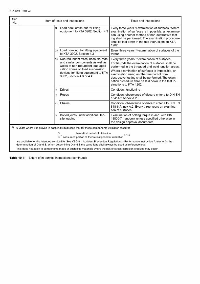
KTA 3903 Page 22
Ser. No.
Item of tests and inspections Tests and inspections
f) Load hook cross-bar for lifting equipment to KTA 3902, Section 4.3
Every three years 1) examination of surfaces. Where examination of surfaces is impossible, an examina-tion using another method of non-destructive test-ing shall be performed. The examination procedure shall be laid down in the test instructions to KTA 1202.
g) Load hook nut for lifting equipment to KTA 3902, Section 4.3
Every three years 1) examination of surfaces of the thread
h) Non-redundant axles, bolts, tie-rods, and similar components as well as welds of non-redundant load appli-cation zones on load suspension devices for lifting equipment to KTA 3902, Section 4.3 or 4.4
Every three years 1) examination of surfaces.
For tie-rods the examination of surfaces shall be performed in the threaded and weld junction areas.
Where examination of surfaces is impossible, an examination using another method of non-destructive testing shall be performed. The exami-nation procedure shall be laid down in the test in-structions to KTA 1202.
i) Drives Condition, functioning
j) Ropes Condition, observance of discard criteria to DIN EN 13414-2 Annex A.2.3
k) Chains Condition, observance of discard criteria to DIN EN 818-6 Annex A.2. Every three years an examina-tion of surfaces.
l) Bolted joints under additional ten-sile loading
Examination of bolting torque in acc. with DIN 18800-7 (random), unless specified otherwise in the design approval documents
1) 6 years where it is proved in each individual case that for these components utilization reserves
5.1nutilizatioofperiodltheoreticaofportionconsumed
nutilizatioofperiodltheoretica
S
D>=
are available for the intended service life. See VBG 8 – Accident Prevention Regulations - Performance instruction Annex A for the determination of D and S. When determining D and S the same load shall always be used as reference load.
This does not apply to components made of austenitic materials where the risk of stress corrosion cracking may occur.
Table 10-1: Extent of in-service inspections (continued)

KTA 3903 Page 23
11 Series-production parts and standard components
This Section comprises series-production and standard pro-duction part to be used for hoists and load suspension devic-es.
11.1 Series-production parts
11.1.1 General
(1) The tests and inspections for series-production parts in the load path shall be performed and documented in accord-ance with this Section.
(2) The manufacturer of series-production parts shall have been certified to DIN EN ISO 9001 or shall have a quality management system proved in conformance with the re-quirements of KTA 1401, section 13. This proof shall be sub-mitted along with the confirmed qualification test to clause 11.1.4.2 for final inspection. This requirement also applies to hoist motors if proof has to be rendered for its motor shaft to meet the requirements of sub-clause 5.1.4 (1)(c).
11.1.2 Design approval
11.1.2.1 Documents
The design data required for dimensioning shall be submitted. Forms C-4 to C-9 contain notices on the extent of the design data for brakes, couplings (excluding brake disks), rope drum hinge connections, rope pulleys, rope end terminations (e.g. rope sockets). For rope drum hinge connections the design calculation shall be additionally contained in the documents. For motor shafts the requirements of sub-clause 5.1.4 (1) c) apply. For other series-production parts in the load path, forms analogous to forms C-4 to C-9 shall be established for the qualification test to clause 11.1.4.2 shall be established and be submitted for design approval.
11.1.2.2 Performance
The documents submitted in accordance with clause 11.1.2.1 shall be examined for correctness of the design loads, taking the drive mechanisms and rope drives classification into ac-count. For rope drum hinge connections the design calcula-tion shall be additionally reviewed.
11.1.3 Materials
The manufacturer's quality department shall confirm that the materials specified in the design calculation have been used.
11.1.4 Final inspection
11.1.4.1 Documents
The documents subjected to design approval in accordance with clause 11.1.2.2 shall be submitted.
11.1.4.2 Qualification test
(1) The manufacturer shall confirm that the series-production part to be used complies with specified design data. The measuring results obtained in the tests and record-ed accordingly shall be submitted to the inspector. Forms C-4 to C-9 contain relevant information for brakes, couplings (ex-cluding brake disks), rope drum hinge connections, rope pul-leys, rope end terminations (e.g. rope sockets). For motor shafts the requirements of sub-clause 5.1.4 (1) c) apply. The manufacturer shall ensure the uniform quality of series-production parts.
(2) In the case of type-approved series-production parts it will suffice to confirm that the series-production part to be
used has been manufactured in the same way as the type-approved part.
(3) The assessment of the suitability of the safety brake shall be effected by the authorized inspector on the basis of the submitted design approval and qualification documents.
11.2 Standard components
11.2.1 General
The tests and inspections for standard components, such as pins, sleeves, bolts, feather keys, turnbuckles shall be per-formed in accordance with this Section.
11.2.2 Design approval
11.2.2.1 Documents
(1) For standard components it will suffice to indicate stand-ard designations and dimensions.
(2) The design data relevant to dimensioning shall be sub-mitted for design approval.
(3) Design calculations shall be submitted for standard components without specification of allowable loadings in the standards.
11.2.2.2 Performance
The documents submitted in acc. with clause 11.2.2.1 shall be examined for correctness of the design loads as well as for completeness and correctness of the calculation.
Note: The correct loadings assumed shall be those loads obtained from 6.1.1, 7.1.1 or 8.1.1 of KTA 3902 in consideration of the appropri-ate live load factor.
11.2.3 Materials
(1) The materials shall be selected with respect to the standards for standard components.
(2) As far as materials tests sheets for standard compo-nents are available in Annex A, the materials tests and exam-inations shall be performed in acc. with these sheets.
(3) The manufacturer shall confirm that the materials speci-fied by the standards have been used. The materials tests and examinations required by these standards shall be per-formed, and the certificates specified in these standards shall be submitted.
11.2.4 Final inspection
The manufacturer shall confirm that the standard component to be used has been manufactured in compliance with the requirements of the respective standard.
12 Series-production electric hoists with rope and
series-production hoist transmissions
12.1 General
(1) The design approval, final inspection, acceptance tests, and in-service inspections shall be performed and document-ed in acc. with this Section.
(2) The scope of this Section comprises, for series-production electric hoists with rope, their lateral transport drives incl. load support structure, hoists and bottom block with load hook. This Section does not apply to bottom blocks incl. load hooks for lifting equipment to KTA 3902, Section 4.3 or 4.4.

KTA 3903 Page 24
(3) The manufacturer of series-production electric hoists and series-production hoist transmissions shall have been certified to DIN EN ISO 9001. Proof of certification shall be submitted for design approval.
12.2 Design approval
12.2.1 Documents
The following documents shall be submitted in a clearly ar-ranged and reviewable form for design approval. The docu-ments mentioned in clauses 12.2.1.1 to 12.2.1.3 shall only be established for components in the load path, and the docu-ments mentioned in clause 12.2.1.5 shall be established for safety equipment or functions.
12.2.1.1 General arrangement and construction drawings, parts lists incl. data on materials
The requirements of clause 5.1.3 subpara. a) to e) as well as g) to i) shall be taken into consideration.
12.2.1.2 Strength calculations
The requirements of clause 5.1.4 shall be taken into conside-ration.
12.2.1.3 Welding data
The data required for the production and assessment of welded joints shall be contained in the construction drawings or in the welding procedure specification and weld location sheet.
12.2.1.4 Welder's and welding procedure qualification
The requirements of clause 5.1.7 shall be taken into conside-ration.
12.2.1.5 Electrical equipment
The requirements of clause 5.1.8 shall be taken into conside-ration.
12.2.1.6 Operating and maintenance instructions
Operating and maintenance instructions shall be submitted at the latest at commencement of acceptance testing.
Note: For the establishment of operating and maintenance instructions see also DIN EN 62079.
12.2.1.7 Test and inspection sequence plan for final inspec-tion
The test and inspection sequence plan for final inspection shall contain the following data:
a) requirements and extent of inspection as per Section 12.4,
b) inspection sequence as well as type of inspection andcertificates,
c) inspector (manufacturer, authorized inspector).
12.2.1.8 Test and inspection sequence plan for acceptance testing
The test and inspection sequence plan for acceptance testing shall contain the following data:
a) requirements and extent of testing as per Section 12.5,
b) test sequence.
12.2.1.9 Test and inspection sequence plan for in-service inspections
The test and inspection sequence plan for in-service inspec-tions shall contain the following data:
a) requirements and extent of inspections as per Sec-tion 12.7,
b) inspection intervals.
12.2.2 Performance of design approval
The requirements of Section 5.2 shall be taken into conside-ration.
12.3 Materials
(1) The manufacturer's quality department shall confirm (QA certificate) that the materials specified by the design calcula-tion have been used. For load-bearing components (except for the transmission casings) the tests and inspections re-quired by the material test certificates to Annex A shall be performed and be certified with acceptance inspection certifi-cate 3.1 to DIN EN 10204 (2005-01).
Note: See clause 5.1.5 as to the use of acceptance inspection certificates to DIN EN 10204 (1995-08).
(2) For load hooks only materials to DIN 15400 are permit-ted. The materials shall be certified in acc. with DIN 15404-1.
(3) The requirements of clause 6.2 (3) shall apply to gears to DIN 3990-5.
(4) For ropes Annex A, materials test sheet WPB 3.18 shall apply.
12.4 Final inspection
12.4.1 General
(1) All stages of inspection as well as the certificates re-quired shall be laid down in the test and inspection sequence plan for final inspection.
(2) The tests and inspections specified in Tables 12-1 and
12-2 for
a) running wheels incl. wheel bearing of lateral transportdrives with related load support structures,
b) series-production electric hoists with rope incl. bottomblock with load hook,
c) series-production hoist transmissions,
d) electrical equipment
shall be performed by the manufacturer to an extent of 100 % inspection, in which case the requirements of sub-clause (3) apply as regards the performance of non-destructive tests on welds.
(3) The manufacturer shall perform non-destructive tests on welds to the following extent:
Each weld shall be subjected to a visual examination. In addi-tion, the following supplementary examinations shall be per-formed:
a) Butt welds of special and normal quality to DIN 15018-1,Table 24 which lie in the load path shall be fully subjected to
aa) an examination of surfaces and
ab) an ultrasonic or radiographic examination.
In the case of butt welds with normal quality and stressesoccurring on the weld less than 0.8 . σzul an examinationextent of 25 % will suffice.
Here, the following applies: For butt welds with wall thick-nesses equal to or smaller than 15 mm radiography shall

KTA 3903 Page 25
preferably be used, alternatively ultrasonic testing; for wall thicknesses greater than 15 mm and equal to or smaller than 40 mm ultrasonic testing shall preferably be used, al-ternatively radiography. For wall thicknesses exceeding 40 mm ultrasonic testing shall be used.
For all wall thicknesses of austenitic butt welds radio-graphy shall be used.
b) Other welds of special quality to DIN 15018-1, Table 24,with full penetration at the root (e.g. double-bevel grooveweld), which lie in in the load path shall be subjected to anextent of 100 % to
ba) an examination of surfaces and
bb) an ultrasonic or radiographic examination.
c) All other welds in the load path shall be subjected to anexamination of surfaces to the following extent:
ca) 25 % if the lifting equipment is classified under KTA3902, sections 4.3/4.4 and the stress occurring on the weld is equal to or greater than 0.8 ⋅ σzul,
cb) 10 % if the lifting equipment is classified under KTA 3902, section 4.2 and the stress occurring on the weld is equal to or greater than 0.8 ⋅ σzul.
Here, the extent of examination shall equally cover the weld-ing work done by all welders.
(3) The extent of inspection to be performed by the author-ized inspector is indicated in Tables 12-1 and 12-2 with re-gard to the various inspection stages.
12.4.2 Documents for final inspection
In addition to the test and inspection sequence plan for final inspection the following documents shall be submitted:
a) construction drawings with welding data and parts listswith data on materials in acc. with cIauses 12.2.1.1 and12.2.1.3,
b) materials certificates and quality department certificate onthe materials used in acc. with cIause 12.3,
c) welder's and welding procedure qualification. in acc. withcIause 12.2.1.4,
d) construction documents for electrical equipment in acc.with clause 12.2.1.5.
12.4.3 Extent of inspection
The extent of final inspection shall be taken from Tables 12-1 and 12-2. Non-destructive testing shall be performed in acc. with Annex B.
12.4.4 Final test at the manufacturer's works
(1) The series-production electric hoists shall be subjected to a final test on a load test bench of the manufacturer in the presence of the authorized inspector. During this test the following shall be tested:
a) operation without load,
b) operation under nominal load or with the respective ropetraction force,
c) operation under maximum test load or with the respectiverope traction force,
d) determination of motor power consumption,
e) check of the braking and limit stop devices.
(2) Recording of the tests shall be effected in accordance with Form C-10.
12.5 Acceptance testing
(1) Acceptance testing shall be performed in accordance with Section 8.
(2) A repetition of the tests already performed during the final test at the manufacturer's works in acc. with clause 12.4.4 can be waived within acceptance testing.
12.6 Operation and maintenance
The requirements of Section 9 shall be taken into account.
12.7 In-service inspection
In-service inspections shall be performed in acc. with Section 10. The check for "condition of wear parts" in acc. with Table10-1, ser. no. 2.1.5 b) is omitted.
12.8 Documentation
The documentation shall be effected in acc. with Section 13.
13 Documentation
13.1 General
The documentation shall make it possible to trace back all manufacturing processes and test/inspection procedures, maintenance measures as well as in-service inspections of Sections 5 to 12, respectively.
13.2 Compilation of documents
(1) The documents shall be compiled in due consideration of requirements in KTA 1404.
(2) The compiled documents shall contain the design ap-proved documents as well as all certificates, records and attestations certifying the actual condition and the tests and inspections performed.
13.3 Performance of documentation
(1) The documentation of manufacturing documents shall accompany the manufacturing process. The manufacturer shall take care to ensure that the documents are complete and also include subcontractors' documents.
(2) The licensee is responsible for continuing the documen-tation with regard to maintenance measures and in-service inspections.

KTA 3903 Page 26
Ser. No. Component Tests and inspections
Inspection by authorized in-spector in acc. with § 20 of the Atomic Energy Act for
lifting equipment to KTA 3902
Section 4.2 Section 4.3 or 4.4
1 Running wheels (incl.
wheel bearing of lateral
transport drives) with
related load support
structures
a) Material identification marks of components for compli-ance with list of material certificates or parts list
b) For tensile-loaded components (in thickness direction) anultrasonic test for detecting laminations in weld-junctionareas
c) Check for compliance of dimensions and assembly withdesign approval documents
X X
d) Observance of welding data
e) Non-destructive testing of welds specified in the test andinspection sequence plan for final inspection:The welds subject to non-destructive testing shall be fixedin acc. with DIN 15018-1, Table 24.
- Visual examination of weld surfaces 25 % 25 %
- Examination of surfaces as well as ultrasonic test orradiography on welds according to clauses 12.4.1 (3) a) and 12.4.1 (3) b):
Welds with particular quality acc. to DIN 15018-1: special quality 25 % 100 %
normal quality - existing stress in the weld ≥ 0.8 ⋅ σzul 25 % 100 %
- existing stress in the weld < 0.8 ⋅ σzul 10 % 25 %
- Examination of surfaces according to clause 12.4.1 (3) c) 10 % 25 %
f) Examination of repair welds in acc. with a design-approved repair welding procedure specification
X X
g) Observance of the design requirements and bolting torqueof pre-tensioned bolted joints
10 % 10 %
h) Fabrication tolerances of running wheels and their bear-ings as well as trolley travelling rails in acc. with tolerancecategory 2 of VDI 3571
i) Fabrication tolerances of craneways to tolerance class 2 ofVDI 3576
2 Hoists from the motor
up to and incl. the car-
rying rope
2.1 General Check for compliance of complete assembly with the design approval documents
X X
2.2 Motors Recording in accordance with Form C-10 X X
2.3 Brakes, couplings, rope pulleys and rope end terminations
Proof of suitability of individually fabricated parts for compli-ance with the design data
a) Recording to Form C-5 X X
b) Compliance of manufacturer’s data in Forms C-4 and C-6
to C-9 with the design dataX X
2.4 Transmissions
2.4.1 General a) Compliance of the design with the data in Form C-1
b) Submission of acceptance inspection certificates accord-ing to Section 12.3
X X
c) Manufacturer's identification marks on antifriction bearingsfor compliance with the design approval documents
X X
d) Check for compliance of dimensions and assembly withdesign approval documents and incorporation of filled-inForm C-1
X X
Table 12-1: Extent of final inspection for series-production electric hoists with rope

KTA 3903 Page 27
Ser. No. Component Tests and inspections
Inspection by authorized in-spector in acc. with § 20 of the Atomic Energy Act for
lifting equipment to KTA 3902
Section 4.2 Section 4.3 or 4.4
2.4.2 Transmission casings a) Review of the design in accordance with the design ap-proved documents
b) Surface examination at machined bearings in acc. withAnnex B
X X
2.4.3 Gear wheels and pinion shafts
a) Examination of surfaces of tooth profiles in finished condi-tion 100 %
In addition, in the case of welded design:
b) Observance of welding data
c) Examination of surfaces of welds specified in the test andinspection sequence plan for final inspection 25 % 25 %
2.4.4 Axles and shafts Examination of surfaces in finished condition 25 % 100 %
2.5 Interference fits Attestation that the design of interference fits conforms to the state-of-the-art
2.6 Ropes and rope end terminations
a) Rope identification mark for compliance with the data indi-cated on the certificate X X
b) Rope dimensions and rope end terminations for compli-ance of data with design approval documents X X
2.7 Rope drums a) Check for compliance of dimensions and assembly withdesign approval documents X X
b) Submission of acceptance inspection certificates accord-ing to Section 12.3
X X
c) Observance of welding data
d) Non-destructive testing of welds specified in the test andinspection sequence plan for final inspection:The welds subject to non-destructive testing shall be fixedin acc. with DIN 15018-1, Table 24.
- Visual examination of weld surfaces 25 % 25 %
- Examination of surfaces as well as ultrasonic test orradiography on welds according to clauses 12.4.1 (3) a) and 12.4.1 (3) b):
Welds with particular quality acc. to DIN 15018-1: special quality 25 % 100 %
normal quality - existing stress in the weld ≥ 0.8 ⋅ σzul 25 % 100 %
- existing stress in the weld < 0.8 ⋅ σzul 10 % 25 %
- Examination of surfaces according to clause 12.4.1 (3) c) 10 % 25 %
e) Manufacturer's identification marks on antifriction bearingsfor compliance with the design approval documents X X
3 Bottom block with load
hook
a) Receiving inspection of identification marks and stamp-ings, if any, on the product forms
b) Submission of acceptance inspection certificates accord-ing to clause 12.3
c) Load hook identification for compliance with the data inthe certificate
X
d) Check for compliance of dimensions and assembly withdesign approval documents
X
e) Observance of welding data X
Table 12-1: Extent of final inspection for series-production electric hoists with rope (continued)
X

KTA 3903 Page 28
Ser. No. Component Tests and inspections
Inspection by authorized in-spector in acc. with § 20 of the Atomic Energy Act for
lifting equipment to KTA 3902
Section 4.2 Section 4.3 or 4.4
f) Non-destructive testing of welds specified in the test andinspection sequence plan for final inspection:The welds subject to non-destructive testing shall be fixedin acc. with DIN 15018-1, Table 24.
- Visual examination of weld surfaces 25 %
- Examination of surfaces as well as ultrasonic test orradiography on welds according to clauses 12.4.1 (3) a) and 12.4.1 (3) b):
Welds with particular quality acc. to DIN 15018-1: special quality 25 %
normal quality - existing stress in the weld ≥ 0.8 ⋅ σzul 25 %
- existing stress in the weld < 0.8 ⋅ σzul 10 %
- Examination of surfaces according to clause 12.4.1 (3) c) 10 %
g) Examination of surfaces within the area of machined sur-faces in finished condition 25 %
h) Examination of surfaces of load hook saddle 100 %
i) Manufacturer's identification marks on antifriction bearingsfor compliance with the design approval documents X
4 Electrical equipment a) Check for compliance of the construction with the designapproval documents X X
b) Check of identification marking of electrical components(rating plate) for compliance with design approval docu-ments, cabling
X X
c) Check of wiring, connections, line penetrations, and fuseprotection X X
5 Series-production
electric hoist Trial run on test bench at the manufacturer's works in accord-ance with Form C-10 X X
X Partial inspection by authorized inspector, i.e. inspection to enable the inspector to confirm that the objectives of the respective inspec-tion stage have been attained.
No inspection by the inspector.
% Percentage share of inspection by the authorized inspector.
Table 12-1: Extent of final inspection for series-production electric hoists with rope (continued)

KTA 3903 Page 29
Ser. No. Component Tests and inspections
Inspection by authorized in-spector in acc. with § 20 of the Atomic Energy Act for
lifting equipment to KTA 3902
Section 4.2 Section 4.3 or 4.4
1 General a) Compliance of the design with the data in Form C-1
b) Submission of acceptance inspection certificates accord-ing to Section 12.3
c) Manufacturer's identification marks on antifriction bearingsfor compliance with the design approval documents X X
d) Check for compliance of dimensions and assembly withdesign approval documents and incorporation of filled-inForm C-1
X X
e) Trial run under part load (recording in acc. with Form C-2) X
2 Transmission casings a) Review of the design in acc. with the design approval doc-uments
b) Surface examination at machined bearings to Annex B X X
3 Gear wheels and pinion shafts
a) Examination of surfaces of tooth profiles in finished condi-tion
100 %
In addition, in the case of welded design:
b) Adherence to dimensions for weld preparation
c) Examination of surfaces of welds specified in the test andinspection sequence plan for final inspection 25 % 25 %
4 Axles and shafts Examination of surfaces in finished condition 25 % 100 %
5 Interference fits Confirmation that interference fits have been designed to the state of technology
X inspection by authorized inspector, i.e. inspection to enable the inspector to confirm that the objectives of the respective inspection stage have been attained.
No inspection by the inspector.
% Percentage share of inspection by the authorized inspector.
Table 12-2: Extent of final inspection for series-production hoist transmissions
X X

KTA 3903 Page 30
Annex A
Materials test sheets (WPB)
WPB Component group 1: Load support structures
1.1 Hot rolled plates and sheets, strips, wide flats and steel sections of structural carbon steel to DIN EN 10025-2
1.2 Hot rolled bars made of structural carbon steels to DIN EN 10025-2
1.3 Forged bars and open-die forgings made of general structural steels to DIN EN 10250-2
1.4 Welded tubes made of carbon steels to DIN EN 10217-1
1.5 Seamless tubes made of carbon steels to DIN EN 10216-1
1.6 Seamless or welded hot finished hollow sections of structural carbon steels to DIN EN 10210-1
1.7 Bolts and nuts ≤ M 39 to DIN EN ISO 898-1, DIN EN ISO 898-2 and DIN EN ISO 3269
1.8 Plates, sheets and strips made of quenched and tempered steels to DIN EN 10025-6
WPB Component group 2: Transmissions and drive parts for hoists (machine parts between motor cou-pling and load carrying means)
2.1 Hot rolled plates and sheets, strips, wide flats and steel sections of structural carbon steel to DIN EN 10025-2
2.2 Hot rolled bars made of structural carbon steels to DIN EN 10025-2
2.3 Forged bars and open-die forgings made of general structural steels to DIN EN 10250-2
2.4 Bars and forgings made of quenched and tempered steels to DIN EN 10083-2, DIN EN 10083-3 or SEW 550
2.5 Induction or flame hardened gears and pinion shafts of material quality MQ to DIN 3990-5
2.6 Gas nitrided gears and pinion shafts of material quality MQ to DIN 3990-5
2.7 Bars and forgings made of case-hardened steels to DIN EN 10084
2.8 Gears and pinion shafts of material quality MQ to DIN 3990-5 made of case-hardened steels to DIN EN 10084
2.9 Bars and forgings made of nitrided steels to DIN EN 10085
2.10 Plates, sheets and strips made of austenitic steels to DIN EN 10088-2
2.11 Bars and forgings made of austenitic steels to DIN EN 10088-3 or DIN EN 10250-4
2.12 Bars and forgings made of stainless martensitic steels to DIN EN 10088-3 or DIN EN 10250-4

KTA 3903 Page 31
WPB Component group 3: Load carrying means, load carrying attachments and load attachment rigging
3.1 Hot rolled plates and sheets, strips, wide flats and steel sections of structural carbon steel to DIN EN 10025-2
3.2 Hot rolled bars made of structural carbon steels to DIN EN 10025-2
3.3 Forged bars and open-die forgings made of general structural steels to DIN EN 10250-2
3.4 Welded tubes made of carbon steels to DIN EN 10217-1
3.5 Seamless tubes made of carbon steels to DIN EN 10216-1
3.6 Seamless or welded hot finished hollow sections of structural carbon steels to DIN EN 10210-1
3.7 Bars and forgings made of quenched and tempered steels to DIN EN 10083-2, DIN EN 10083-3 or SEW 550
3.8 Forged load hooks to DIN 15400
3.9 Bars and forgings for load hook nuts to DIN 15413 made of quenched and tempered steels to DIN EN 10083-2, DIN EN 10083-3 or SEW 550
3.10 Bars and forgings for load hook cross-bars made of quenched and tempered steels to DIN EN 10083-2, DIN EN 10083-3 or SEW 550
3.11 Plates, sheets and strips made of austenitic steels to DIN EN 10088-2 and of ferritic-austenitic steels to DIN EN 10028-7
3.12 Bars and forgings made of austenitic steels to DIN EN 10088-3 or DIN EN 10250-4 and of ferritic-austenitic steels to DIN EN 10222-5 or DIN EN 10272
3.13 Seamless tubes made of austenitic steels to DIN EN 10216-5
3.14 Forged load hooks made of austenitic steels to DIN EN 10250-4
3.15 Bars and forgings for load hook nuts made of austenitic steels to DIN EN 10088-3 or DIN EN 10250-4
3.16 Bars and forgings for load hook cross-bars made of austenitic steels to DIN EN 10088-3 or DIN EN 10250-4
3.17: Bolts and studs, thread rolled, head bolts with forged-on head, and subsequently heat-treated
3.18 Ropes to DIN EN 12385-1 and DIN EN 12385-2 as well as non-standard ropes
3.19 Sling ropes to DIN EN 13414-1, DIN EN 13414-2 and DIN EN 13414-3
3.20 Sling chains to DIN EN 818-4 as well as components for load attachment rigging to DIN EN 1677-1, DIN EN 1677-2, DIN EN 1677-3 and DIN EN 1677-4
3.21 Welded tubes made of austenitic steels to DIN EN 10217-7
3.22 Bars and forgings made of stainless martensitic steels to DIN EN 10088-3 or DIN EN 10250-4
3.23 Bolts and nuts ≤ M 39 to DIN EN ISO 898-1, DIN EN ISO 898-2 and DIN EN ISO 3269
3.24 Bolts and nuts made of austenitic steels to DIN EN ISO 3506-1, DIN EN ISO 3506-2 and DIN EN ISO 3269
3.25: Terminations with ferrules to DIN EN 13411-3 for steel wire ropes
3.26: Terminations with ferrules for steel wire rope slings to DIN EN 13414-1
3.27: Plates, sheets and strips made of quenched and tempered steels to DIN EN 10025-6
WPB Component group 4: Running wheels and their axles and shafts
4.1 Hot rolled components made of structural carbon steels to DIN EN 10025-2
4.2 Forged components made of structural carbon steels to DIN EN 10250-2
4.3 Forged or rolled components made of quenched and tempered steels to DIN EN 10083-2, DIN EN 10083-3 or SEW 550
4.4 Bright steel made of carbon steels to DIN EN 10277-2, DIN EN 10277-4 or DIN EN 10277-5
4.5 Running wheels made of cast steel to DIN EN 10293 or cast steel for pressure vessels to DIN EN 10213
WPB Component group 5: Other components for hoists
5.1 Brake disks made of spheroidal graphite cast iron to DIN EN 1563
5.2 Hot rolled plates and sheets of structural carbon steel to DIN EN 10025-2 for brake drums and brake disks

KTA 3903 Page 32
Materials test sheet 1.1: Hot rolled plates and sheets, strips, wide flats and steel sections of structural carbon steel to DIN EN 10025-2
MATERIALS TEST SHEET WPB 1.1
Component group: Load support structures
Product form: Hot rolled plates and sheets, strips, wide flats and steel sections
Materials: S235J0 1) (1.0114), S235J2 (1.0117), S235JR (1.0038), S355J2 (1.0577), S355K2 (1.0596)
Requirements: DIN EN 10025-1, DIN EN 10025-2 2), DIN EN 10164
Tests and inspectionsCertificate to DIN EN 10204 (2005-01) 3)
Classification of lifting equipment in acc. with KTA 3902:
additional requirements to Section 4.2
increased requirements to Section 4.3 or 4.4
1. Chemical composition:
Ladle analysis 3.1 3.1
2. Attestation of heat treatment condition or of as-delivered condition
3.1 3.1
3. Tensile test at room temperature:
3.1 One test per lot delivered 3.1
3.2 One specimen per melt and test unit 3.1
3.3 Three tensile specimens in thickness direction for product thicknesses > 20 mm and tensile loading in thickness direction:
Test unit to DIN EN 10164 4) Quality grade Z 25 to DIN EN 10164 3.1
4. Notched bar impact test at test temperature toDIN EN 10025-2:
4.1 One test per lot delivered 3.1
4.2 One set of impact test specimen per tensile test specimen as per no. 3.2 as far as the nominal dimension is ≥ 6 mm
3.1
5. Visual inspection and dimensional check:
Each component 3.1
See Table 7-1 ser. no. 1 c) regarding ultrasonic testing of components under tensile loading in thickness direction.
Material identification:
Manufacturer's mark, steel grade, melt number, specimen number or identification number (the plate, sheet or strip number may also be used as specimen number), inspector's mark, Z 25 (if demonstrated); for lifting equipment to KTA 3902 Section 4.2 only manufacturer's mark and steel grade
1) For the material S235J0 certificate 2.2 will suffice if the lifting equipment is classified under KTA 3902, Section 4.2.2) Repair welding is not permitted.3) See clause 5.1.5 as to the use of acceptance inspection certificates to DIN EN 10204 (1995-08).4) Where the materials S235J0 and S235JR are loaded in thickness direction, the test shall be performed on each rolled panel in
acc. with test no. 3.3.

KTA 3903 Page 33
Materials test sheet 1.2: Hot rolled bars made of structural carbon steels to DIN EN 10025-2
MATERIALS TEST SHEET WPB 1.2
Component group: Loadsupport structures
Product form: Hot-rolled bars
Materials: S235J0 (1.0114) 1), S235J2 (1.0117), S235JR (1.0038), S355J2 (1.0577), S355K2 (1.0596)
Requirements: DIN EN 10025-1, DIN EN 10025-2 2)
Tests and inspections
Certificate to DIN EN 10204 (2005-01) 3) Classification of lifting equipment in acc. with KTA 3902:
additional requirements to Section 4.2
increased requirements to Section 4.3 or 4.4
1. Chemical composition:
Ladle analysis
3.1
3.1
2. Attestation of heat treatment condition or of as-delivered condition
3.1 3.1
3. Tensile test at room temperature:
3.1 One test per lot delivered 3.1
3.2 One specimen per melt and test unit 3.1
4. Notched bar impact test at test temperature to DIN EN 10025-2 and nominal dimensions to DIN EN 10025-1:
4.1 One test per lot delivered 3.1
4.2 One set of impact test specimen per tensile test specimen as per no. 3.2
3.1
5. Visual inspection and dimensional check:
Each component
3.1
Material identification:
Manufacturer's mark, steel grade, melt number, specimen number or identification number, inspector's mark; for lifting equipment to KTA 3902 Section 4.2 only manufacturer's mark and steel grade
1) For the material S235J0 certificate 2.2 will suffice if the lifting equipment is classified under KTA 3902, Section 4.2. 2) Repair welding is not permitted. 3) See clause 5.1.5 as to the use of acceptance inspection certificates to DIN EN 10204 (1995-08).

KTA 3903 Page 34
Materials test sheet 1.3: Forged bars and open-die forgings made of general structural steels to DIN EN 10250-2
MATERIALS TEST SHEET WPB 1.3
Component group: Loadsupport structures
Product form: Forged bars and open-die forgings
Materials: S235JRG2 (1.0038), S235J2G3 (1.0116), S355J2G3 (1.0570)
Requirements: DIN EN 10250-1, DIN EN 10250-2 1)
Tests and inspectionsCertificate to DIN EN 10204 (2005-01) 2)
Classification of lifting equipment in acc. with KTA 3902:
additional requirements to Section 4.2
increased requirements to Section 4.3 or 4.4
1. Chemical composition:
Ladle analysis 3.1 3.1
2. Attestation of heat treatment condition 3.1 3.1
3. Tensile test at room temperature:
One specimen per melt and test unit 3.1 3.1
4. Notched bar impact test at test temperature toDIN EN 10250-2:
One set of impact test specimen per tensile testspecimen as far as the nominal dimension is≥ 15 mm 3.1 3.1
5. Visual inspection and dimensional check:
Each component 3.1 3.1
Material identification:
Manufacturer's mark, steel grade, melt number, specimen number or identification number, inspector's mark
1) Repair welding is not permitted.2) See clause 5.1.5 as to the use of acceptance inspection certificates to DIN EN 10204 (1995-08).

KTA 3903 Page 35
Materials test sheet 1.4: Welded tubes made of carbon steels to DIN EN 10217-1
MATERIALS TEST SHEET WPB 1.4
Component group: Load support structures
Product form: Welded tubes
Materials: P235TR1 1) (1.0254), P235TR2 (1.0255), P265TR1 (1.0258), P265TR2 (1.0259)
Requirements: DIN EN 10217-1 2)
Tests and inspectionsCertificate to DIN EN 10204 (2005-01) 3)
Classification of lifting equipment in acc. with KTA 3902:
additional requirements to Section 4.2
increased requirements to Section 4.3 or 4.4
1. Chemical composition:
Ladle analysis 3.1 3.1
2. Attestation of heat treatment condition or of as-delivered condition 3.1 3.1
3. Tensile test at room temperature (base material):
3.1 One test per lot delivered 3.1
3.2 Lot size and extent of testing in acc. with DIN EN 10217-1 no. 10.1, Table 12 and Table 13
3.1
4. Tensile test at room temperature transverse to theweld (at an outside diameter DA > 508 mm):
4.1 One test per lot delivered 3.1
4.2 Lot size and extent of testing in acc. with DIN EN 10217-1 no 10.1, Table 12 and Table 13
3.1
5. Notched bar impact test at test temperature of0 °C (base material) in the case of materialsno. 1.0255 and 1.0259:
One set of impact test specimen per tensile testspecimen
3.1
6. Flattening test or drift-expanding test:
6.1 One test per lot delivered 3.1
6.2 Lot size and extent of testing in acc. with DIN EN 10217-1 no 10.1, Table 12 and Table 13
3.1
7. Weld bend test on submerged-arc welded tubes:
7.1 One test per lot delivered 3.1
7.2 Lot size and extent of testing in acc. with DIN EN 10217-1 no 10.1, Table 12 and Table 13
3.1
8. Non-destructive testing of welds:
In acc. with DIN EN 10217-1 Section 11.11 3.1 3.1
9. Tightness test:
Each tube in acc. with DIN EN 10217-1 Sec. 11.8 3.1 3.1
10. Visual inspection and dimensional check:
Each tube 3.1 3.1
Material identification:
Manufacturer's mark, steel grade, melt number, specimen number or identification number, inspector's mark, type of tube in acc. with DIN EN 10217-1 Table 1; for lifting equipment to KTA 3902 Section 4.2 only manufacturer's mark, steel grade and type of tube.
1) For the materials P235TR1 and P265TR1 certificate 2.2 will suffice if the lifting equipment is classified under KTA 3902, Section 4.2.2) Repair welding in the base material is not permitted.3) See clause 5.1.5 as to the use of acceptance inspection certificates to DIN EN 10204 (1995-08).

KTA 3903 Page 36
Materials test sheet 1.5: Seamless tubes made of carbon steels to DIN EN 10216-1
MATERIALS TEST SHEET WPB 1.5
Component group: Load support structures
Product form: Seamless tubes
Materials: P235TR1 1) (1.0254), P235TR2 (1.0255), P265TR1 1) (1.0258), P265TR2 (1.0259)
Requirements: DIN EN 10216-1 2)
Tests and inspections
Certificate to DIN EN 10204 (2005-01) 3) Classification of lifting equipment in acc. with KTA 3902:
additional requirements to Section 4.2
increased requirements to Section 4.3 or 4.4
1. Chemical composition:
Ladle analysis
3.1
3.1
2. Attestation of heat treatment condition or of as-delivered condition
3.1
3.1
3. Tensile test at room temperature:
3.1 One test per lot delivered 3.1
3.2 Lot size and extent of testing in acc. with DIN EN 10216-1 no 10.1, Table 9 and Table 10
3.1
4. Notched bar impact test at test temperature of 0 °C in the case of materials no. 1.0255 and 1.0259:
One set of impact test specimen per tensile test specimen
3.1
5. Tightness test:
Each tube in acc. with DIN EN 10216-1 Sec. 11.4
3.1
3.1
6. Visual inspection and dimensional check:
Each tube
3.1
3.1
Material identification:
Manufacturer's mark, steel grade, melt number, specimen number or identification number, inspector's mark; for lifting equipment to KTA 3902 Section 4.2 only manufacturer's mark and steel grade
1) For the materials P235TR1 and P265TR1 certificate 2.2 will suffice if the lifting equipment is classified under KTA 3902, Section 4.2. 2) Repair welding is not permitted. 3) See clause 5.1.5 as to the use of acceptance inspection certificates to DIN EN 10204 (1995-08).
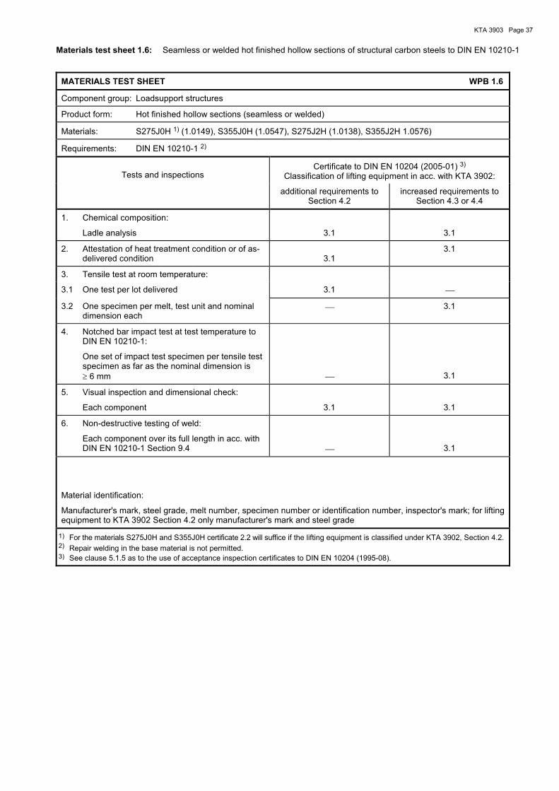
KTA 3903 Page 37
Materials test sheet 1.6: Seamless or welded hot finished hollow sections of structural carbon steels to DIN EN 10210-1
MATERIALS TEST SHEET WPB 1.6
Component group: Loadsupport structures
Product form: Hot finished hollow sections (seamless or welded)
Materials: S275J0H 1) (1.0149), S355J0H (1.0547), S275J2H (1.0138), S355J2H 1.0576)
Requirements: DIN EN 10210-1 2)
Tests and inspectionsCertificate to DIN EN 10204 (2005-01) 3)
Classification of lifting equipment in acc. with KTA 3902:
additional requirements to Section 4.2
increased requirements to Section 4.3 or 4.4
1. Chemical composition:
Ladle analysis 3.1 3.1
2. Attestation of heat treatment condition or of as-delivered condition 3.1
3.1
3. Tensile test at room temperature:
3.1 One test per lot delivered 3.1
3.2 One specimen per melt, test unit and nominal dimension each
3.1
4. Notched bar impact test at test temperature toDIN EN 10210-1:
One set of impact test specimen per tensile testspecimen as far as the nominal dimension is≥ 6 mm 3.1
5. Visual inspection and dimensional check:
Each component 3.1 3.1
6. Non-destructive testing of weld:
Each component over its full length in acc. withDIN EN 10210-1 Section 9.4 3.1
Material identification:
Manufacturer's mark, steel grade, melt number, specimen number or identification number, inspector's mark; for lifting equipment to KTA 3902 Section 4.2 only manufacturer's mark and steel grade
1) For the materials S275J0H and S355J0H certificate 2.2 will suffice if the lifting equipment is classified under KTA 3902, Section 4.2.2) Repair welding in the base material is not permitted.3) See clause 5.1.5 as to the use of acceptance inspection certificates to DIN EN 10204 (1995-08).

KTA 3903 Page 38
Materials test sheet 1.7: Bolts and nuts ≤ M 39 to DIN EN ISO 898-1, DIN EN ISO 898-2 and DIN EN ISO 3269
MATERIALS TEST SHEET WPB 1.7
Component group: Loadsupport structures
Product form: Bolts and nuts ≤ M 39
Materials: Property classes
Bolts 4.6, 5.6, 6.8, 8.8 and 10.9
Nuts 5, 6, 8 and 10
Requirements: Bolts: DIN EN ISO 898-1, DIN EN ISO 3269, DIN EN 26157-3
(Testing of mechanical properties in accordance with DIN EN ISO 898-1, test series MP1 plus additional re-tempering test in connection with DIN EN 26157-3. Where test series MP1 is not practicable, test series MP2 plus re-tempering test may be performed.)
Nuts: DIN EN ISO 898-2, DIN EN ISO 3269, DIN EN ISO 6157-2
For high-strength bolted joints (10.9): for bolts and nuts additionally DIN EN 14399-4 washers DIN EN 14399-6, DIN 6917 and DIN 6918
Tests and inspections
Certificate to DIN EN 10204 (2005-01) 1) Classification of lifting equipment in acc. with KTA 3902:
additional requirements to Section 4.2
increased requirements to Section 4.3 or 4.4
Proof (by continuous recording in the manufacturer's works) that the requirements regarding mechanical properties, surface condition and dimensional accu-racy have been met
2.2 2) or 3.1 3)
2.2 2) or 3.1 3)
Material identification:
Bolts in acc. with DIN EN ISO 898-1, for high-strength bolting additionally in acc. with DIN EN 14399-4
Nuts in acc. with DIN EN ISO 898-2, for high-strength bolting additionally in acc. with DIN EN 14399-4
Washers for high-strength bolting in acc. with DIN EN 14399-6, DIN 6917 and DIN 6918
1) See clause 5.1.5 as to the use of acceptance inspection certificates to DIN EN 10204 (1995-08). 2) In lieu of the certificate 2.2 stamping will suffice if the manufacturer is recognized in acc. with VdTÜV instruction sheet 1253/4 3) For bolts of property classes 8.8 and 10.9 as well as for nuts of property classes 8 and 10 a certificate 3.1 is required.

KTA 3903 Page 39
Materials test sheet 1.8: Plates, sheets and strips made of quenched and tempered steels to DIN EN 10025-6
MATERIALS TEST SHEET WPB 1.8
Component group: Loadsupport structures
Product form: Plates, sheets and strips
Materials: S460QL1 (1.8916), S500QL1 (1.8984), S690QL1 (1.8988)
Requirements: DIN EN 10025-1, DIN EN 10025-6 1), DIN EN 10163-2 class B3, DIN EN 10164
Tests and inspectionsCertificate to DIN EN 10204 (2005-01) 2)
Classification of lifting equipment in acc. with KTA 3902:
additional requirements to Section 4.2
increased requirements to Section 4.3 or 4.4
1. Chemical composition:
Ladle analysis 3.1 3.1
2. Attestation of heat treatment condition 3.1 3.1
3. Tensile test at room temperature:
3.1 One specimen per melt and test unit 3.1 3.1
3.2 Three tensile specimens in thickness direction for product thicknesses > 15 mm and tensile loading in thickness direction:
Test unit to DIN EN 10164 Quality grade Z 25 to DIN EN 10164 3.1 3.1
4. Notched bar impact test at test temperature toDIN EN 10025-6:
One set of impact test specimen per tensile testspecimen as per no. 3.1 as far as the nominalthickness is ≥ 6 mm 3.1 3.1
5. Visual inspection and dimensional check:
Each component 3.1 3.1
See Table 7-1 ser. no. 1 c) regarding ultrasonic testing of components under tensile loading in thickness direction.
Material identification:
Manufacturer's mark, steel grade, melt number, specimen number or identification number (the plate, sheet or strip number may also be used as specimen number), inspector's mark, Z 25 (if demonstrated)
1) Repair welding is not permitted.2) See clause 5.1.5 as to the use of acceptance inspection certificates to DIN EN 10204 (1995-08).

KTA 3903 Page 40
Materials test sheet 2.1: Hot rolled plates and sheets, strips, wide flats and steel sections of structural carbon steel to DIN EN 10025-2
MATERIALS TEST SHEET WPB 2.1
Component group: Transmissions and drive parts for hoists (machine parts between motor coupling and load carry-ing means)
Product form: Hot rolled plates and sheets, strips, wide flats and steel sections
Materials: S235J0 (1.0114), S235J2 (1.0117), S235JR (1.0038), S355J2 (1.0577), S355K2 (1.0596)
Requirements: DIN EN 10025-1, DIN EN 10025-2 1), DIN EN 10164
Tests and inspections
Certificate to DIN EN 10204 (2005-01) 2) Classification of lifting equipment in acc. with KTA 3902:
additional requirements to Section 4.2
increased requirements to Section 4.3 or 4.4
1. Chemical composition:
Ladle analysis
3.1
3.1
2. Attestation of heat treatment condition or of as-delivered condition
3.1
3.1
3. Tensile test at room temperature:
3.1 One specimen per melt, test unit and thickness range each
3.1
3.1
3.2 Three tensile specimens in thickness direction for product thicknesses > 20 mm and tensile loading in thickness direction:
Test unit to DIN EN 10164 3) Quality grade Z 25 to DIN EN 10164
3.1
3.1
4. Notched bar impact test at test temperature to DIN EN 10025-2:
One set of impact test specimen per tensile test specimen as per no. 3.1 as far as the nominal dimension is ≥ 6 mm
3.1
3.1
5. Visual inspection and dimensional check:
Each component
3.1
3.1
Material identification:
Manufacturer's mark, steel grade, melt number, specimen number or identification number (the plate, sheet or strip number may also be used as specimen number), inspector's mark, Z 25 (if demonstrated)
1) Repair welding is not permitted.
2) See clause 5.1.5 as to the use of acceptance inspection certificates to DIN EN 10204 (1995-08). 3) Where the materials S235J0 and S235JR are loaded in thickness direction, the test shall be performed on each rolled panel in
acc. with test no. 3.2.

KTA 3903 Page 41
Materials test sheet 2.2: Hot rolled bars made of structural carbon steels to DIN EN 10025-2
MATERIALS TEST SHEET WPB 2.2
Component group: Transmissions and drive parts for hoists (machine parts between motor coupling and load carry-ing means)
Product form: Hot rolled bars
Materials: S235J0 (1.0114), S235J2 (1.0117), S235JR (1.0038), S355J2 (1.0577), S355K2 (1.0596)
Requirements: DIN EN 10025-1, DIN EN 10025-2 1)
Tests and inspections
Certificate to DIN EN 10204 (2005-01) 2) Classification of lifting equipment in acc. with KTA 3902:
additional requirements to Section 4.2
increased requirements to Section 4.3 or 4.4
1. Chemical composition:
Ladle analysis
3.1
3.1
2. Attestation of heat treatment condition or of as-delivered condition
3.1
3.1
3. Tensile test at room temperature:
One specimen per melt, test unit and thickness range each
3.1
3.1
4. Notched bar impact test at test temperature to DIN EN 10025-2 and nominal dimensions to DIN EN 10025-1:
One set of impact test specimens per tensile test specimen
3.1
3.1
5. Visual inspection and dimensional check:
Each component
3.1
3.1
6. Ultrasonic testing:
For bar steel with product thicknesses ≥ 30 mm each component subject to 100 % in acc. with Annex B
3.1
3.1
Material identification:
Manufacturer's mark, steel grade, melt number, specimen number or identification number, inspector's mark
1) Repair welding is not permitted. 2) See clause 5.1.5 as to the use of acceptance inspection certificates to DIN EN 10204 (1995-08).

KTA 3903 Page 42
Materials test sheet 2.3: Forged bars and open-die forgings made of general structural steels to DIN EN 10250-2
MATERIALS TEST SHEET WPB 2.3
Component group: Transmissions and drive parts for hoists (machine parts between motor coupling and load carry-ing means)
Product form: Forged bars and open-die forgings
Materials: S235JRG2 (1.0038), S235J2G3 (1.0116), S355J2G3 (1.0570)
Requirements: DIN EN 10250-1, DIN EN 10250-2 1)
Tests and inspections
Certificate to DIN EN 10204 (2005-01) 2) Classification of lifting equipment in acc. with KTA 3902:
additional requirements to Section 4.2
increased requirements to Section 4.3 or 4.4
1. Chemical composition:
Ladle analysis
3.1
3.1
2. Attestation of heat treatment condition 3.1 3.1
3. Tensile test at room temperature:
One specimen per melt, test unit and thickness range each
3.1
3.1
4. Notched bar impact test at test temperature to DIN EN 10250-2:
One set of impact test specimens per tensile test specimen, as far as the nominal dimension is ≥ 15 mm
3.1
3.1
5. Visual inspection and dimensional check:
Each component
3.1
3.1
6. Ultrasonic testing:
For bar steel with product thicknesses ≥ 30 mm and forgings with a weight in final heat treat-ment condition ≥ 300 kg, each component sub-ject to 100 % in acc. with Annex B
3.1
3.1
Material identification:
Manufacturer's mark, steel grade, melt number, specimen number or identification number, inspector's mark
1) Repair welding is not permitted. 2) See clause 5.1.5 as to the use of acceptance inspection certificates to DIN EN 10204 (1995-08).

KTA 3903 Page 43
Materials test sheet 2.4: Bars and forgings made of quenched and tempered steels to DIN EN 10083-2, DIN EN 10083-3 or SEW 550
MATERIALS TEST SHEET WPB 2.4
Component group: Transmissions and drive parts for hoists (machine parts between motor coupling and load carry-ing means)
Product form: Bars and forgings 1)
Materials: Quenched and tempered steels to DIN EN 10083-2, DIN EN 10083-3 or SEW 550
Requirements: DIN EN 10083-1, DIN EN 10083-2 2), DIN EN 10083-3 2) or SEW 550 2)
Tests and inspections
Certificate to DIN EN 10204 (2005-01) 3) Classification of lifting equipment in acc. with KTA 3902:
additional requirements to Section 4.2
increased requirements to Section 4.3 or 4.4
1. Chemical composition:
Ladle analysis
3.1
3.1
2. Attestation of heat treatment condition 3.1 3.1
3. Hardness test for verification of uniform heat treatment:
On one end of each component three measur-ing points each
3.1
3.1
4. Tensile test at room temperature:
One specimen per melt, dimensional range and heat treatment batch each
3.1
3.1
5. Notched bar impact test at room temperature:
One set of impact test specimens per tensile test specimen, as far as the nominal dimension is ≥ 15 mm
3.1
3.1
6. Visual inspection and dimensional check:
Each component
3.1
3.1
7. Materials identification check for alloyed steels:
Each component, e.g. by spectroscopy
3.1
3.1
8. Ultrasonic testing:
For bar steel with product thicknesses ≥ 30 mm and forgings with a weight in final heat treat-ment condition ≥ 300 kg, each component sub-ject to 100 % in acc. with Annex B
3.1
3.1
Material identification:
Manufacturer's mark, steel grade, melt number, specimen number or identification number, inspector's mark
1) The product forms acc. to this materials test sheet also serve as initial material for gears and pinions to NIEMANN (see KTA 3902 Table B 1-5) as well as to DIN 3990-5 in acc. with material test sheets WPB 2.5 and WPB 2.6 (see KTA 3902 Table B 1-3).
2) Repair welding is not permitted. 3) See clause 5.1.5 as to the use of acceptance inspection certificates to DIN EN 10204 (1995-08).

KTA 3903 Page 44
Materials test sheet 2.5: Induction or flame hardened gears and pinion shafts of material quality MQ to DIN 3990-5
MATERIALS TEST SHEET WPB 2.5
Component group: Transmissions and drive parts for hoists (only gears and pinion shafts to DIN 3990-5)
Product form: Gears and pinion (material quality MQ) 1)
Materials: C45E+N (1.1191), 42CrMo4 +QT (1.7225) to WPB 2.4
Requirements: DIN EN 10083-2 2), DIN EN 10083-3 2), SEW 550 2), DIN 3990-5
Tests and inspections
Certificate to DIN EN 10204 (2005-01) 4) Classification of lifting equipment in acc. with KTA 3902:
additional requirements to Section 4.2
increased requirements to Section 4.3 or 4.4
1. Tests on production control test specimens (part of gear or pinion)
1.1 Hardness depth 3.1 3.1
1.2 Decrease in hardness to core 2.1 2.1
1.3 Drop in hardness to edge 3.1 3.1
1.4 Hardness traverse 3.1 3.1
1.5 Edge structure 3.1 3.1
1.6 Percentage of ferrite in core structure 3.1 3.1
1.7 Tensile test at room temperature 3) 3.1 3.1
1.8 Notched bar impact test at room temperature 3) 3.1 3.1
2. Tests on finished part
2.1 Surface hardness 3.1 3.1
2.2 Examination of surfaces
Each component 100 % for hardness cracks in acc. with Annex B
3.1
3.1
2.3 Visual inspection and dimensional check by using Form C-1 of KTA 3903
3.1
3.1
Material identification:
Manufacturer's mark, steel grade, melt number, specimen number or identification number, inspector's mark
1) See materials test sheet WPB 2.4 regarding requirements for initial materials. 2) Repair welding is not permitted. 3) Only for pinion shafts; characteristic values to manufacturer's specification. 4) See clause 5.1.5 as to the use of acceptance inspection certificates to DIN EN 10204 (1995-08).
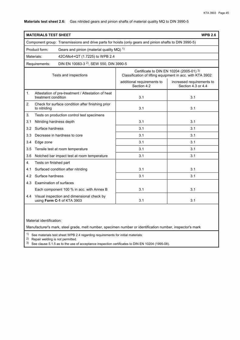
KTA 3903 Page 45
Materials test sheet 2.6: Gas nitrided gears and pinion shafts of material quality MQ to DIN 3990-5
MATERIALS TEST SHEET WPB 2.6
Component group: Transmissions and drive parts for hoists (only gears and pinion shafts to DIN 3990-5)
Product form: Gears and pinion (material quality MQ) 1)
Materials: 42CrMo4+QT (1.7225) to WPB 2.4
Requirements: DIN EN 10083-3 2), SEW 550, DIN 3990-5
Tests and inspections
Certificate to DIN EN 10204 (2005-01) 3) Classification of lifting equipment in acc. with KTA 3902:
additional requirements to Section 4.2
increased requirements to Section 4.3 or 4.4
1. Attestation of pre-treatment / Attestation of heat treatment condition
3.1
3.1
2. Check for surface condition after finishing prior to nitriding
3.1
3.1
3. Tests on production control test specimens
3.1 Nitriding hardness depth 3.1 3.1
3.2 Surface hardness 3.1 3.1
3.3 Decrease in hardness to core 3.1 3.1
3.4 Edge zone 3.1 3.1
3.5 Tensile test at room temperature 3.1 3.1
3.6 Notched bar impact test at room temperature 3.1 3.1
4. Tests on finished part
4.1 Surfaced condition after nitriding 3.1 3.1
4.2 Surface hardness 3.1 3.1
4.3 Examination of surfaces
Each component 100 % in acc. with Annex B
3.1
3.1
4.4 Visual inspection and dimensional check by using Form C-1 of KTA 3903
3.1
3.1
Material identification:
Manufacturer's mark, steel grade, melt number, specimen number or identification number, inspector's mark
1) See materials test sheet WPB 2.4 regarding requirements for initial materials. 2) Repair welding is not permitted. 3) See clause 5.1.5 as to the use of acceptance inspection certificates to DIN EN 10204 (1995-08).

KTA 3903 Page 46
Materials test sheet 2.7: Bars and forgings made of case-hardened steels to DIN EN 10084
MATERIALS TEST SHEET WPB 2.7
Component group: Transmissions and drive parts for hoists (machine parts between motor coupling and load carry-ing means)
Product form: Bars and forgings 1)
Materials 2): 16MnCr5+HH+FP (1.7131), 20MnCr5+HH+FP (1.7147), 18CrNiMo7-6+HH+FP (1.6587)
Requirements: DIN EN 10084 2) and supplementary sheet to this materials test sheet
Tests and inspectionsCertificate to DIN EN 10204 (2005-01) 3)
Classification of lifting equipment in acc. with KTA 3902:
additional requirements to Section 4.2
increased requirements to Section 4.3 or 4.4
1. Chemical composition:
Ladle analysis 3.1 3.1
2. Attestation of heat treatment condition of blank-hardened test bar 3.1 3.1
3. Tensile test at room temperature:
One specimen per melt and dimensional rangeeach on blank-hardened test bar (see suppl.sheet to this materials test sheet) 3.1 3.1
4. Visual inspection and dimensional check:
Each component 3.1 3.1
5. Material identification check:
Each component, e.g. by spectroscopy 3.1 3.1
6. Ultrasonic testing:
For bar steel with product thicknesses ≥ 30 mmand forgings with a weight in final heat treat-ment condition ≥ 300 kg, each component sub-ject to 100 % in acc. with Annex B 3.1 3.1
Material identification:
Manufacturer's mark, steel grade, melt number, specimen number or identification number, inspector's mark
1) The product forms acc. to this materials test sheet also serve as initial material for gears and pinions to NIEMANN (see KTA3902,Table B 1-5) as well as to DIN 3990-5 in acc. with material test sheet WPB 2.8 (see KTA 3902, Table B 1-3).
2) Repair welding is not permitted.3) See clause 5.1.5 as to the use of acceptance inspection certificates to DIN EN 10204 (1995-08).
Supplementary sheet to materials test sheet WPB 2.7
Steel grade Diameter 1)
mm
Yield stress Re
N/mm2 min.
Tensile strength
Rm, N/mm2
Elongation at fracture
A, % min. value
Reduction of area
Z, % min. value
Blank hardening temperature
°C ± 10 K
11 630 900 to 1200 9 35 870
16MnCr5+HH+FP 30 600 800 to 1100 10 40 870
63 450 650 to 950 11 40 870
11 730 1100 to 1400 7 30 870
20MnCr 5+HH+FP 30 680 1000 to 1300 8 35 870
63 550 800 to 1100 10 35 870
11 830 1150 to 1450 7 30 860
18CrNiMo7-6+HH+FP 30 780 1050 to 1350 8 35 860
63 680 950 to 1250 8 35 860
1) Specimen location: Diameter 11 mm and 30 mm : Specimen taken from core in longitudinal direction
Diameter 63 mm : Specimen taken in longitudinal direction at a distance of 12.5 mm from the surface of the product
Other sections or greater dimensions shall be rolled or forged down to these diameters before hardening.

KTA 3903 Page 47
Materials test sheet 2.8: Gears and pinion shafts of material quality MQ to DIN 3990-5 made of case-hardened steels to DIN EN 10084
MATERIALS TEST SHEET WPB 2.8
Component group: Transmissions and drive parts for hoists (only gears and pinion shafts to DIN 3990-5)
Product form: Gears and pinion (material quality MQ) 1)
Materials: 16MnCr5+HH+FP (1.7131), 20MnCr5+HH+FP (1.7147), 18CrNiMo7-6+HH+FP (1.6587) to WPB 2.7
Requirements: DIN EN 10084 2), DIN 3990-5
Tests and inspectionsCertificate to DIN EN 10204 (2005-01) 3)
Classification of lifting equipment in acc. with KTA 3902:
additional requirements to Section 4.2
increased requirements to Section 4.3 or 4.4
1. Tests on production control test specimens
1.1 Edge hardness 3.1 3.1
1.2 Core hardness 3.1 3.1
1.3 Core structure 3.1 3.1
1.4 Case-hardening depth 3.1 3.1
1.5 Surface zone in finished condition 3.1 3.1
a) surface structure
b) surface decarbonisation
c) carbide precipitation
d) residual austenite
e) surface oxidation
1.6 Tensile test at room temperature 4) 3.1 3.1
1.7 Notched bar impact test at room temperature 4) 3.1 3.1
2. Tests on finished part
2.1 Edge hardness on part
Type and extent of testing to DIN 3990-5, Table 5 ser. no. 7 3.1 3.1
2.2. Test for overheating
Type and extent of testing to DIN 3990-5, Table 5 ser. no. 14 3.1 3.1
2.3 Examination of surfaces of both flanks in fin-ished condition
Each component 100 % magnetic particle testing Performance: to Annex B; Acceptance criteria: indications which suggest the presence of crack-like defects are not permitted 3.1 3.1
2.4 Visual inspection and dimensional check by using Form C-1 of KTA 3903 3.1 3.1
Material identification:
Manufacturer's mark, steel grade, melt number, specimen number or identification number, inspector's mark
1) See materials test sheet WPB 2.7 regarding requirements for initial materials.2) Repair welding is not permitted.3) See clause 5.1.5 as to the use of acceptance inspection certificates to DIN EN 10204 (1995-08).4) Only for pinion shafts; characteristic values to manufacturer's specification.

KTA 3903 Page 48
Materials test sheet 2.9: Bars and forgings made of nitrided steels to DIN EN 10085
MATERIALS TEST SHEET WPB 2.9
Component group: Transmissions and drive parts for hoists (machine parts between motor coupling and load carry-ing means)
Product form: Bars and forgings
Materials: Nitrided steels to DIN EN 10085
Requirements: DIN EN 10085 1)
Tests and inspections
Certificate to DIN EN 10204 (2005-01) 2) Classification of lifting equipment in acc. with KTA 3902:
additional requirements to Section 4.2
increased requirements to Section 4.3 or 4.4
1. Chemical composition:
Ladle analysis
3.1
3.1
2. Attestation of heat treatment condition 3.1 3.1
3. Tensile test at room temperature:
One specimen per melt, heat treatment and dimensional range each
3.1
3.1
4. Notched bar impact test at room temperature:
One set of impact test specimens per tensile test specimen, as far as the nominal dimension is ≥ 15 mm
3.1
3.1
5. Visual inspection and dimensional check:
Each component
3.1
3.1
6. Material identification check:
Each component, e.g. by spectroscopy
3.1
3.1
7. Ultrasonic testing:
For bar steel with product thicknesses ≥ 30 mm and forgings with a weight in final heat treat-ment condition ≥ 300 kg, each component sub-ject to 100 % in acc. with Annex B
3.1
3.1
Material identification:
Manufacturer's mark, steel grade, melt number, specimen number or identification number, inspector's mark
1) Repair welding is not permitted. 2) See clause 5.1.5 as to the use of acceptance inspection certificates to DIN EN 10204 (1995-08).

KTA 3903 Page 49
Materials test sheet 2.10: Plates, sheets and strips made of austenitic steels to DIN EN 10088-2
MATERIALS TEST SHEET WPB 2.10
Component group: Transmissions and drive parts for hoists (machine parts between motor coupling and load carry-ing means)
Product form: Plates, sheets and strips
Materials: Austenitic steels to DIN EN 10088-2
Requirements: DIN EN 10088-2 1)
Tests and inspectionsCertificate to DIN EN 10204 (2005-01) 2)
Classification of lifting equipment in acc. with KTA 3902:
additional requirements to Section 4.2
increased requirements to Section 4.3 or 4.4
1. Chemical composition:
Ladle analysis 3.1 3.1
2. Attestation of heat treatment condition 3.1 3.1
3. Check for intergranular corrosion 3:
One specimen per melt and heat treatmentbatch each 3.1 3.1
4. Tensile test at room temperature:
One specimen to DIN EN 10088-2 Table 21 3.1 3.1
5. Visual inspection and dimensional check:
Each component; surface condition in acc. withmanufacturer's specification 3.1 3.1
6. Material identification check:
Each component, e.g. by spectroscopy 3.1 3.1
Material identification:
Manufacturer's mark, steel grade, melt number, specimen number or identification number (the plate, sheet or strip number may also be used as specimen number), inspector's mark
1) Repair welding is not permitted.2) See clause 5.1.5 as to the use of acceptance inspection certificates to DIN EN 10204 (1995-08).3) According to DIN EN ISO 3651-2 procedure A sensitisation T1 or T2 and only if components are welded and are in contact with
water.
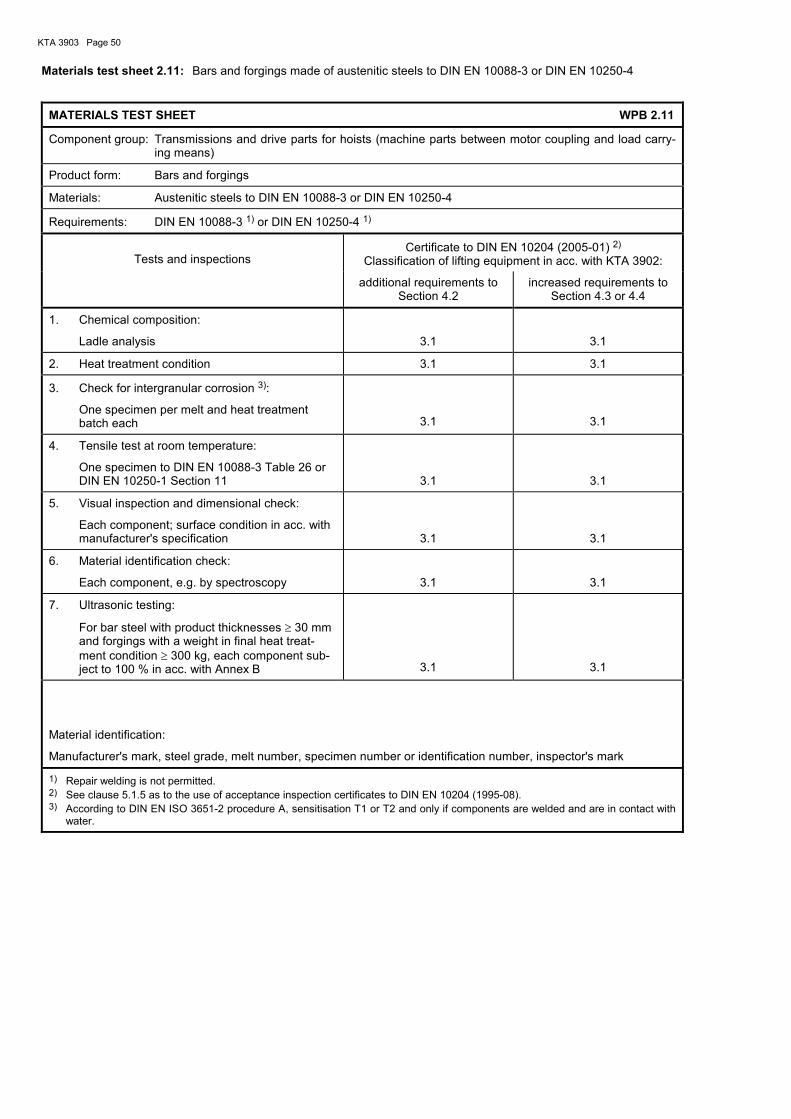
KTA 3903 Page 50
Materials test sheet 2.11: Bars and forgings made of austenitic steels to DIN EN 10088-3 or DIN EN 10250-4
MATERIALS TEST SHEET WPB 2.11
Component group: Transmissions and drive parts for hoists (machine parts between motor coupling and load carry-ing means)
Product form: Bars and forgings
Materials: Austenitic steels to DIN EN 10088-3 or DIN EN 10250-4
Requirements: DIN EN 10088-3 1) or DIN EN 10250-4 1)
Tests and inspections
Certificate to DIN EN 10204 (2005-01) 2) Classification of lifting equipment in acc. with KTA 3902:
additional requirements to Section 4.2
increased requirements to Section 4.3 or 4.4
1. Chemical composition:
Ladle analysis
3.1
3.1
2. Heat treatment condition 3.1 3.1
3. Check for intergranular corrosion 3):
One specimen per melt and heat treatment batch each
3.1
3.1
4. Tensile test at room temperature:
One specimen to DIN EN 10088-3 Table 26 or DIN EN 10250-1 Section 11
3.1
3.1
5. Visual inspection and dimensional check:
Each component; surface condition in acc. with manufacturer's specification
3.1
3.1
6. Material identification check:
Each component, e.g. by spectroscopy
3.1
3.1
7. Ultrasonic testing:
For bar steel with product thicknesses ≥ 30 mm and forgings with a weight in final heat treat-ment condition ≥ 300 kg, each component sub-ject to 100 % in acc. with Annex B
3.1
3.1
Material identification:
Manufacturer's mark, steel grade, melt number, specimen number or identification number, inspector's mark
1) Repair welding is not permitted. 2) See clause 5.1.5 as to the use of acceptance inspection certificates to DIN EN 10204 (1995-08). 3) According to DIN EN ISO 3651-2 procedure A, sensitisation T1 or T2 and only if components are welded and are in contact with
water.

KTA 3903 Page 51
Materials test sheet 2.12: Bars and forgings made of stainless martensitic steels to DIN EN 10088-3 or DIN EN 10250-4
MATERIALS TEST SHEET WPB 2.12
Component group: Transmissions and drive parts for hoists (machine parts between motor coupling and load carry-ing means)
Product form: Bars and forgings
Materials: X17CrNi16-2 - QT800 (1.4057), X39CrMo17-1 - QT750 (1.4122), X3CrNiMo13-4 - QT780 (1.4313)
Requirements: DIN EN 10088-3 1) or DIN EN 10250-4 1)
Tests and inspectionsCertificate to DIN EN 10204 (2005-01) 2)
Classification of lifting equipment in acc. with KTA 3902:
additional requirements to Section 4.2
increased requirements to Section 4.3 or 4.4
1. Chemical composition:
Ladle analysis 3.1 3.1
2. Attestation of heat treatment condition(for 1.4313 indication of strength grade) 3.1 3.1
3. Tensile test at room temperature:
Test lot and extent of testing to DIN EN 10088-3Table 26 or DIN EN 10250-1 Section 11 3.1 3.1
4. Notched bar impact test at room temperature:
Test lot and extent of testing as for tensile test(only for nominal dimension ≥ 15 mm) 3.1 3.1
5. Visual inspection and dimensional check:
Each component, surface quality and dimen-sions in acc. with manufacturer's specification 3.1 3.1
6. Material identification check:
Each component, e.g. by spectroscopy 3.1 3.1
7. Ultrasonic testing:
For bar steel with product thicknesses ≥ 30 mmand forgings with a weight in final heat treat-ment condition ≥ 300 kg, each component sub-ject to 100 % in acc. with Annex B 3.1 3.1
Material identification:
Manufacturer's mark, steel grade, melt number, specimen number or identification number, inspector's mark
1) Repair welding is not permitted.2) See clause 5.1.5 as to the use of acceptance inspection certificates to DIN EN 10204 (1995-08).
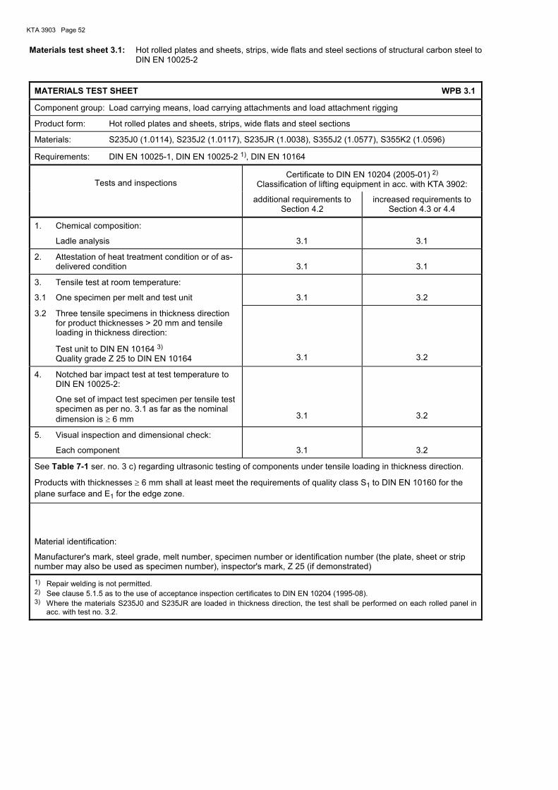
KTA 3903 Page 52
Materials test sheet 3.1: Hot rolled plates and sheets, strips, wide flats and steel sections of structural carbon steel to DIN EN 10025-2
MATERIALS TEST SHEET WPB 3.1
Component group: Load carrying means, load carrying attachments and load attachment rigging
Product form: Hot rolled plates and sheets, strips, wide flats and steel sections
Materials: S235J0 (1.0114), S235J2 (1.0117), S235JR (1.0038), S355J2 (1.0577), S355K2 (1.0596)
Requirements: DIN EN 10025-1, DIN EN 10025-2 1), DIN EN 10164
Tests and inspections
Certificate to DIN EN 10204 (2005-01) 2) Classification of lifting equipment in acc. with KTA 3902:
additional requirements to Section 4.2
increased requirements to Section 4.3 or 4.4
1. Chemical composition:
Ladle analysis
3.1
3.1
2. Attestation of heat treatment condition or of as-delivered condition
3.1
3.1
3. Tensile test at room temperature:
3.1 One specimen per melt and test unit
3.1
3.2
3.2 Three tensile specimens in thickness direction for product thicknesses > 20 mm and tensile loading in thickness direction:
Test unit to DIN EN 10164 3) Quality grade Z 25 to DIN EN 10164
3.1
3.2
4. Notched bar impact test at test temperature to DIN EN 10025-2:
One set of impact test specimen per tensile test specimen as per no. 3.1 as far as the nominal dimension is ≥ 6 mm
3.1
3.2
5. Visual inspection and dimensional check:
Each component
3.1
3.2
See Table 7-1 ser. no. 3 c) regarding ultrasonic testing of components under tensile loading in thickness direction.
Products with thicknesses ≥ 6 mm shall at least meet the requirements of quality class S1 to DIN EN 10160 for the plane surface and E1 for the edge zone.
Material identification:
Manufacturer's mark, steel grade, melt number, specimen number or identification number (the plate, sheet or strip number may also be used as specimen number), inspector's mark, Z 25 (if demonstrated)
1) Repair welding is not permitted. 2) See clause 5.1.5 as to the use of acceptance inspection certificates to DIN EN 10204 (1995-08). 3) Where the materials S235J0 and S235JR are loaded in thickness direction, the test shall be performed on each rolled panel in
acc. with test no. 3.2.
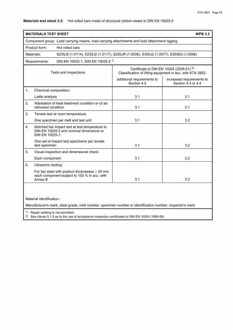
KTA 3903 Page 53
Materials test sheet 3.2: Hot rolled bars made of structural carbon steels to DIN EN 10025-2
MATERIALS TEST SHEET WPB 3.2
Component group: Load carrying means, load carrying attachments and load attachment rigging
Product form: Hot rolled bars
Materials: S235J0 (1.0114), S235J2 (1.0117), S235JR (1.0038), S355J2 (1.0577), S355K2 (1.0596)
Requirements: DIN EN 10025-1, DIN EN 10025-2 1)
Tests and inspectionsCertificate to DIN EN 10204 (2005-01) 2)
Classification of lifting equipment in acc. with KTA 3902:
additional requirements to Section 4.2
increased requirements to Section 4.3 or 4.4
1. Chemical composition:
Ladle analysis 3.1 3.1
2. Attestation of heat treatment condition or of as-delivered condition 3.1 3.1
3. Tensile test at room temperature:
One specimen per melt and test unit 3.1 3.2
4. Notched bar impact test at test temperature toDIN EN 10025-2 and nominal dimensions toDIN EN 10025-1:
One set of impact test specimens per tensiletest specimen 3.1 3.2
5. Visual inspection and dimensional check:
Each component 3.1 3.2
6. Ultrasonic testing:
For bar steel with product thicknesses ≥ 30 mmeach component subject to 100 % in acc. withAnnex B 3.1 3.2
Material identification:
Manufacturer's mark, steel grade, melt number, specimen number or identification number, inspector's mark
1) Repair welding is not permitted.2) See clause 5.1.5 as to the use of acceptance inspection certificates to DIN EN 10204 (1995-08).

KTA 3903 Page 54
Materials test sheet 3.3: Forged bars and open-die forgings made of general structural steels to DIN EN 10250-2
MATERIALS TEST SHEET WPB 3.3
Component group: Load carrying means, load carrying attachments and load attachment rigging
Product form: Forged bars and open-die forgings
Materials: S235JRG2 (1.0038), S235J2G3 (1.00116), S355J2G3 (1.0570)
Requirements: DIN EN 10250-1, DIN EN 10250-2 1)
Tests and inspections
Certificate to DIN EN 10204 (2005-01) 2) Classification of lifting equipment in acc. with KTA 3902:
additional requirements to Section 4.2
increased requirements to Section 4.3 or 4.4
1. Chemical composition:
Ladle analysis
3.1
3.1
2. Attestation of heat treatment condition 3.1 3.1
3. Tensile test at room temperature:
One specimen per melt and test unit
3.1
3.2
4. Notched bar impact test at test temperature to DIN EN 10250-2:
One set of impact test specimens per tensile test specimen, as far as the nominal dimension is ≥ 15 mm
3.1
3.2
5. Visual inspection and dimensional check:
Each component
3.1
3.2
6. Ultrasonic testing:
For bar steel with product thicknesses ≥ 30 mm and forgings with a weight in final heat treat-ment condition ≥ 300 kg, each component sub-ject to 100 % in acc. with Annex B
3.1
3.2
Material identification:
Manufacturer's mark, steel grade, melt number, specimen number or identification number, inspector's mark
1) Repair welding is not permitted. 2) See clause 5.1.5 as to the use of acceptance inspection certificates to DIN EN 10204 (1995-08).

KTA 3903 Page 55
Materials test sheet 3.4: Welded tubes made of carbon steels to DIN EN 10217-1
MATERIALS TEST SHEET WPB 3.4
Component group: Load carrying means, load carrying attachments and load attachment rigging
Product form: Welded tubes
Materials: P235TR1 (1.0254), P235TR2 (1.0255), P265TR1 (1.0258), P265TR2 (1.0259)
Requirements: DIN EN 10217-1 1)
Tests and inspectionsCertificate to DIN EN 10204 (2005-01) 2)
Classification of lifting equipment in acc. with KTA 3902 Section 4.2
1. Chemical composition:
Ladle analysis 3.1
2. Attestation of heat treatment condition or of as-delivered condition 3.1
3. Tensile test at room temperature (base material):
Lot size and extent of testing in acc. withDIN EN 10217-1 no. 10.1, Table 12 and Table 13 3.1
4. Tensile test at room temperature transverse to theweld (at an outside diameter DA > 508 mm):
Lot size and extent of testing in acc. withDIN EN 10217-1 no 10.1, Table 12 and Table 13 3.1
5. Notched bar impact test at test temperature of0 °C (base material) in the case of materialsno. 1.0255 and 1.0259:
One set of impact test specimen per tensile testspecimen 3.1
6. Flattening test or drift-expanding test:
Lot size and extent of testing in acc. withDIN EN 10217-1 no 10.1, Table 12 and Table 13 3.1
7. Weld bend test on submerged-arc weldedtubes:
Lot size and extent of testing in acc. withDIN EN 10217-1 no 10.1, Table 12 and Table 13 3.1
8. Non-destructive testing of welds:
In acc. with DIN EN 10217-1 Section 11.11 3.1
9. Tightness test:
Each tube in acc. with DIN EN 10217-1 Sec. 11.8 3.1
10. Visual inspection and dimensional check:
Each tube 3.1
Material identification:
Manufacturer's mark, steel grade, melt number, specimen number or identification number, inspector's mark, type of tube in acc. with DIN EN 10217-1 Table 1
1) Repair welding in the base material is not permitted.2) See clause 5.1.5 as to the use of acceptance inspection certificates to DIN EN 10204 (1995-08).

KTA 3903 Page 56
Materials test sheet 3.5: Seamless tubes made of carbon steels to DIN EN 10216-1
MATERIALS TEST SHEET WPB 3.5
Component group: Load carrying means, load carrying attachments and load attachment rigging
Product form: Seamless tubes
Materials: P235TR1 (1.0254), P235TR2 (1.0255), P265TR1 (1.0258), P265TR2 (1.0259)
Requirements: DIN EN 10216-1 1)
Tests and inspections Certificate to DIN EN 10204 (2005-01) 2)
Classification of lifting equipment in acc. with KTA 3902 Section 4.2
1. Chemical composition:
Ladle analysis
3.1
2. Attestation of heat treatment condition or of as-delivered condition
3.1
3. Tensile test at room temperature:
Lot size and extent of testing in acc. with DIN EN 10216-1 no 10.1, Table 9 and Table 10
3.1
4. Notched bar impact test at test temperature of 0 °C in the case of materials no. 1.0255 and 1.0259:
One set of impact test specimen per tensile test specimen
3.1
5. Tightness test:
Each tube in acc. with DIN EN 10216-1 Sec. 11.4
3.1
6. Visual inspection and dimensional check:
Each tube
3.1
Material identification:
Manufacturer's mark, steel grade, melt number, specimen number or identification number, inspector's mark
1) Repair welding is not permitted. 2) See clause 5.1.5 as to the use of acceptance inspection certificates to DIN EN 10204 (1995-08).

KTA 3903 Page 57
Materials test sheet 3.6: Seamless or welded hot finished hollow sections of structural carbon steels to DIN EN 10210-1
MATERIALS TEST SHEET WPB 3.6
Component group: Load carrying means, load carrying attachments and load attachment rigging
Product form: Hot finished hollow sections (seamless or welded)
Materials: S275J0H (1.0149), S275J2H (1.0138), S355J0H (1.0547), S355J2H 1.0576)
Requirements: DIN EN 10210-1 1)
Tests and inspectionsCertificate to DIN EN 10204 (2005-01) 2)
Classification of lifting equipment in acc. with KTA 3902:
additional requirements to Section 4.2
increased requirements to Section 4.3 or 4.4
1. Chemical composition:
Ladle analysis 3.1 3.1
2. Attestation of heat treatment condition or of as-delivered condition 3.1 3.1
3. Tensile test at room temperature:
One specimen per melt, test unit and nominaldimension each 3.1 3.2
4. Notched bar impact test at test temperature toDIN EN 10210-1:
One set of impact test specimens per tensiletest specimen, as far as the nominal dimensionis ≥ 6 mm 3.1 3.2
5. Visual inspection and dimensional check:
Each component 3.1 3.2
6. Non-destructive testing of weld:
Each component over its full length in acc. withDIN EN 10210-1 Section 9.4 3.1 3.2
Material identification:
Manufacturer's mark, steel grade, melt number, specimen number or identification number, inspector's mark
1) Repair welding in the base material is not permitted.2) See clause 5.1.5 as to the use of acceptance inspection certificates to DIN EN 10204 (1995-08).

KTA 3903 Page 58
Materials test sheet 3.7: Bars and forgings made of quenched and tempered steels to DIN EN 10083-2, DIN EN 10083-3 or SEW 550
MATERIALS TEST SHEET WPB 3.7
Component group: Load carrying means, load carrying attachments and load attachment rigging
Product form: Bars and forgings
Materials: Quenched and tempered steels to DIN EN 10083-2, DIN EN 10083-3 or SEW 550
Requirements: DIN EN 10083-1, DIN EN 10083-2 1), DIN EN 10083-3 1) or SEW 550 1)
Tests and inspections
The performance of the following tests and inspec-tions shall be verified for the quenched and tempered
condition
Certificate to DIN EN 10204 (2005-01) 2) Classification of lifting equipment in acc. with KTA 3902:
additional requirements to Section 4.2
increased requirements to Section 4.3 or 4.4
1. Chemical composition:
Ladle analysis
3.1
3.1
2. Attestation of heat treatment condition 3.1 3.1
3. Hardness test for verification of uniform heat treatment:
On one end of each component three measur-ing points each
3.1
3.1
4. Tensile test at room temperature:
One specimen per melt, dimensional range and heat treatment batch each
3.1
3.2
5. Notched bar impact test at room temperature:
One set of impact test specimens per tensile test specimen, as far as the nominal dimension is ≥ 15 mm
3.1
3.2
6. Visual inspection and dimensional check:
Each component
3.1
3.2
7. Materials identification check for alloyed steels:
Each component, e.g. by spectroscopy
3.1
3.1
8. Ultrasonic testing:
For bar steel with product thicknesses ≥ 30 mm and forgings with a weight in final heat treat-ment condition ≥ 300 kg each component sub-ject to 100 % in acc. with Annex B
3.1
3.2
Material identification:
Manufacturer's mark, steel grade, melt number, specimen number or identification number, inspector's mark
1) Repair welding is not permitted. 2) See clause 5.1.5 as to the use of acceptance inspection certificates to DIN EN 10204 (1995-08).
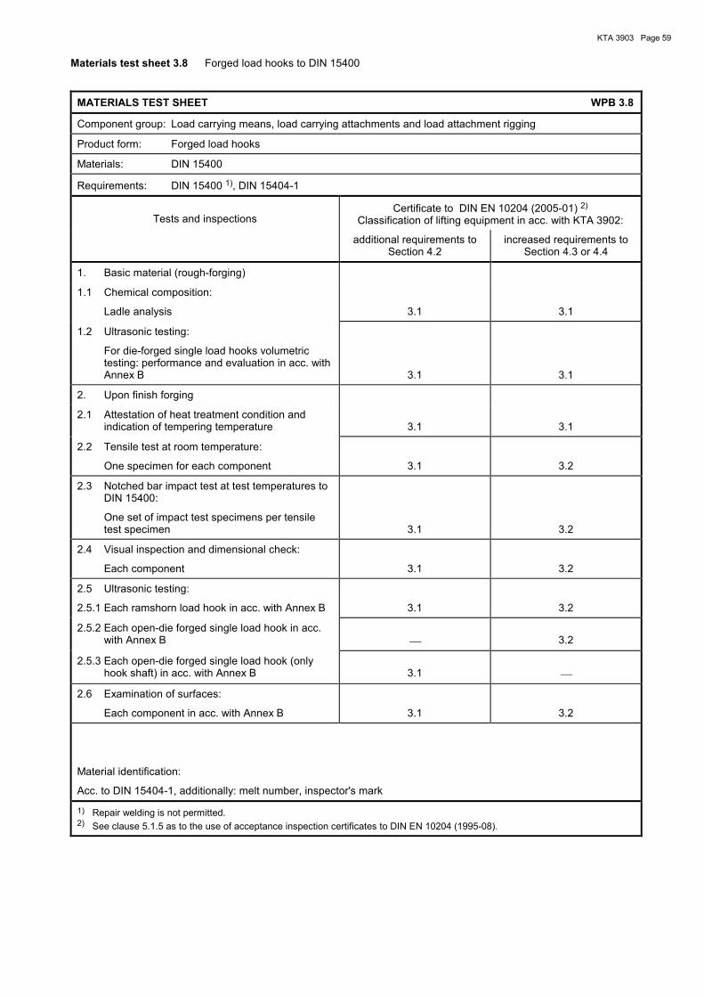
KTA 3903 Page 59
Materials test sheet 3.8 Forged load hooks to DIN 15400
MATERIALS TEST SHEET WPB 3.8
Component group: Load carrying means, load carrying attachments and load attachment rigging
Product form: Forged load hooks
Materials: DIN 15400
Requirements: DIN 15400 1), DIN 15404-1
Tests and inspections
Certificate to DIN EN 10204 (2005-01) 2) Classification of lifting equipment in acc. with KTA 3902:
additional requirements to Section 4.2
increased requirements to Section 4.3 or 4.4
1. Basic material (rough-forging)
1.1 Chemical composition:
Ladle analysis
3.1
3.1
1.2 Ultrasonic testing:
For die-forged single load hooks volumetric testing: performance and evaluation in acc. with Annex B
3.1
3.1
2. Upon finish forging
2.1 Attestation of heat treatment condition and indication of tempering temperature
3.1
3.1
2.2 Tensile test at room temperature:
One specimen for each component
3.1
3.2
2.3 Notched bar impact test at test temperatures to DIN 15400:
One set of impact test specimens per tensile test specimen
3.1
3.2
2.4 Visual inspection and dimensional check:
Each component
3.1
3.2
2.5 Ultrasonic testing:
2.5.1 Each ramshorn load hook in acc. with Annex B
3.1
3.2
2.5.2 Each open-die forged single load hook in acc. with Annex B
3.2
2.5.3 Each open-die forged single load hook (only hook shaft) in acc. with Annex B
3.1
2.6 Examination of surfaces:
Each component in acc. with Annex B
3.1
3.2
Material identification:
Acc. to DIN 15404-1, additionally: melt number, inspector's mark
1) Repair welding is not permitted. 2) See clause 5.1.5 as to the use of acceptance inspection certificates to DIN EN 10204 (1995-08).

KTA 3903 Page 60
Materials test sheet 3.9 Bars and forgings for load hook nuts to DIN 15413 made of quenched and tempered steels to DIN EN 10083-2, DIN EN 10083-3 or SEW 550
MATERIALS TEST SHEET WPB 3.9
Component group: Load carrying means, load carrying attachments and load attachment rigging
Product form: Bars and forgings for load hook nuts to DIN 15413
Materials: Quenched and tempered steels to DIN EN 10083-2, DIN EN 10083-3 or SEW 550
Requirements: DIN EN 10083-21), DIN EN 10083-3 1) or SEW 550 1)
Tests and inspections
Certificate to DIN EN 10204 (2005-01) 2) Classification of lifting equipment in acc. with KTA 3902:
The performance of the following tests and inspec-tions shall be verified for the quenched and tempered
condition
additional requirements to Section 4.2
increased requirements to Section 4.3 or 4.4
1. Chemical composition:
Ladle analysis
3.1
3.1
2. Attestation of heat treatment condition and indication of tempering temperature
3.1
3.1
3. Hardness test for verification of uniform heat treatment:
On both ends of each component three measur-ing points each
3.1
3.1
4. Tensile test at room temperature:
One specimen per melt, dimensional range and heat treatment batch each
3.1
3.2
5. Notched bar impact test at room temperature:
One set of impact test specimens per tensile test specimen
3.1
3.2
6. Visual inspection and dimensional check:
Each component
3.1
3.2
7. Materials identification check for alloyed steels:
Each component, e.g. by spectroscopy
3.1
3.1
8. Ultrasonic testing:
Each component subject to 100 % in acc. with Annex B
3.1
3.2
Material identification:
Manufacturer's mark, steel grade, melt number, specimen number or identification number, inspector's mark
1) Repair welding is not permitted. 2) See clause 5.1.5 as to the use of acceptance inspection certificates to DIN EN 10204 (1995-08).
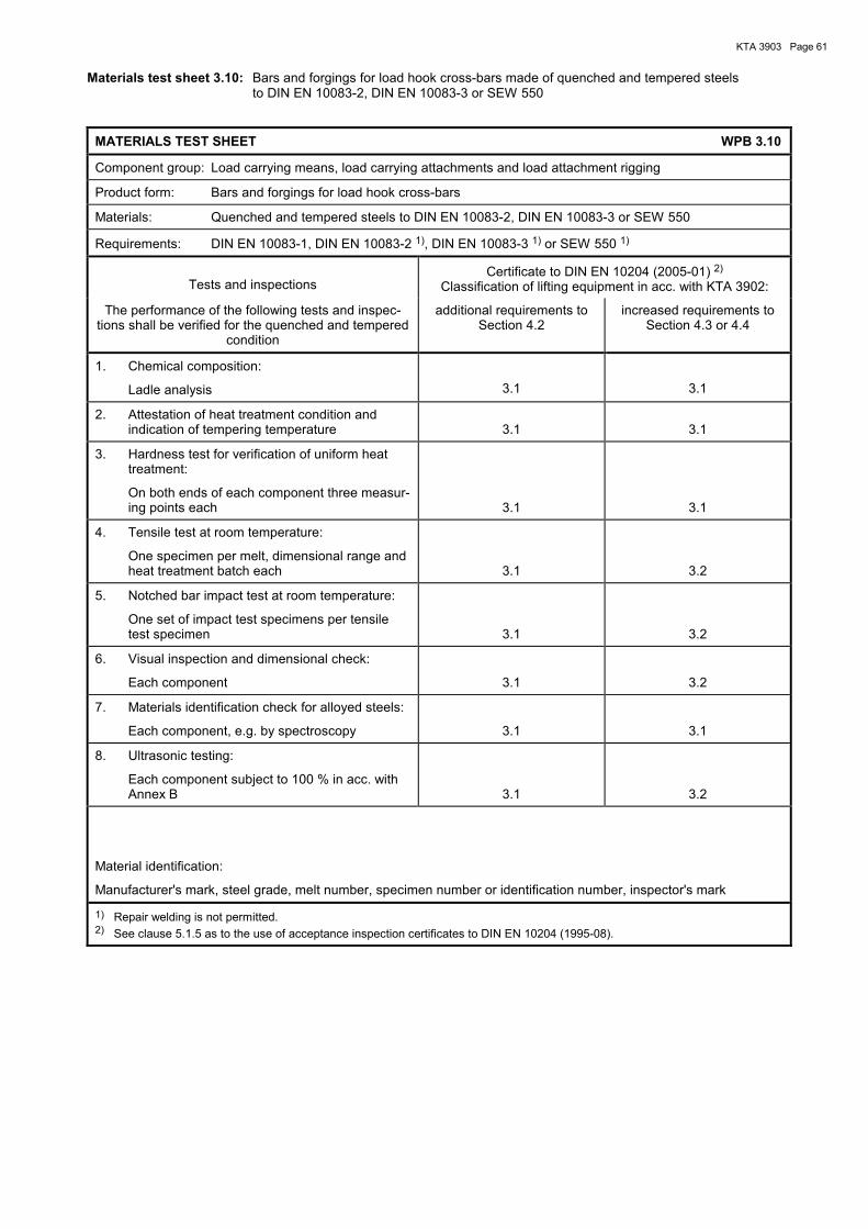
KTA 3903 Page 61
Materials test sheet 3.10: Bars and forgings for load hook cross-bars made of quenched and tempered steels to DIN EN 10083-2, DIN EN 10083-3 or SEW 550
MATERIALS TEST SHEET WPB 3.10
Component group: Load carrying means, load carrying attachments and load attachment rigging
Product form: Bars and forgings for load hook cross-bars
Materials: Quenched and tempered steels to DIN EN 10083-2, DIN EN 10083-3 or SEW 550
Requirements: DIN EN 10083-1, DIN EN 10083-2 1), DIN EN 10083-3 1) or SEW 550 1)
Tests and inspections
Certificate to DIN EN 10204 (2005-01) 2) Classification of lifting equipment in acc. with KTA 3902:
The performance of the following tests and inspec-tions shall be verified for the quenched and tempered
condition
additional requirements to Section 4.2
increased requirements to Section 4.3 or 4.4
1. Chemical composition:
Ladle analysis
3.1
3.1
2. Attestation of heat treatment condition and indication of tempering temperature
3.1
3.1
3. Hardness test for verification of uniform heat treatment:
On both ends of each component three measur-ing points each
3.1
3.1
4. Tensile test at room temperature:
One specimen per melt, dimensional range and heat treatment batch each
3.1
3.2
5. Notched bar impact test at room temperature:
One set of impact test specimens per tensile test specimen
3.1
3.2
6. Visual inspection and dimensional check:
Each component
3.1
3.2
7. Materials identification check for alloyed steels:
Each component, e.g. by spectroscopy
3.1
3.1
8. Ultrasonic testing:
Each component subject to 100 % in acc. with Annex B
3.1
3.2
Material identification:
Manufacturer's mark, steel grade, melt number, specimen number or identification number, inspector's mark
1) Repair welding is not permitted. 2) See clause 5.1.5 as to the use of acceptance inspection certificates to DIN EN 10204 (1995-08).
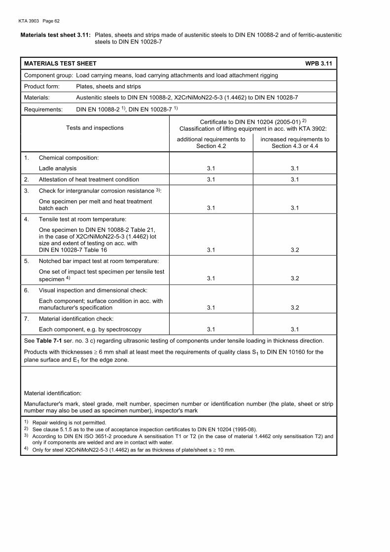
KTA 3903 Page 62
Materials test sheet 3.11: Plates, sheets and strips made of austenitic steels to DIN EN 10088-2 and of ferritic-austenitic steels to DIN EN 10028-7
MATERIALS TEST SHEET WPB 3.11
Component group: Load carrying means, load carrying attachments and load attachment rigging
Product form: Plates, sheets and strips
Materials: Austenitic steels to DIN EN 10088-2, X2CrNiMoN22-5-3 (1.4462) to DIN EN 10028-7
Requirements: DIN EN 10088-2 1), DIN EN 10028-7 1)
Tests and inspections
Certificate to DIN EN 10204 (2005-01) 2) Classification of lifting equipment in acc. with KTA 3902:
additional requirements to Section 4.2
increased requirements to Section 4.3 or 4.4
1. Chemical composition:
Ladle analysis
3.1
3.1
2. Attestation of heat treatment condition 3.1 3.1
3. Check for intergranular corrosion resistance 3):
One specimen per melt and heat treatment batch each
3.1
3.1
4. Tensile test at room temperature:
One specimen to DIN EN 10088-2 Table 21, in the case of X2CrNiMoN22-5-3 (1.4462) lot size and extent of testing on acc. with DIN EN 10028-7 Table 16
3.1
3.2
5. Notched bar impact test at room temperature:
One set of impact test specimen per tensile test specimen 4)
3.1
3.2
6. Visual inspection and dimensional check:
Each component; surface condition in acc. with manufacturer's specification
3.1
3.2
7. Material identification check:
Each component, e.g. by spectroscopy
3.1
3.1
See Table 7-1 ser. no. 3 c) regarding ultrasonic testing of components under tensile loading in thickness direction.
Products with thicknesses ≥ 6 mm shall at least meet the requirements of quality class S1 to DIN EN 10160 for the plane surface and E1 for the edge zone.
Material identification:
Manufacturer's mark, steel grade, melt number, specimen number or identification number (the plate, sheet or strip number may also be used as specimen number), inspector's mark
1) Repair welding is not permitted. 2) See clause 5.1.5 as to the use of acceptance inspection certificates to DIN EN 10204 (1995-08). 3) According to DIN EN ISO 3651-2 procedure A sensitisation T1 or T2 (in the case of material 1.4462 only sensitisation T2) and
only if components are welded and are in contact with water. 4) Only for steel X2CrNiMoN22-5-3 (1.4462) as far as thickness of plate/sheet s ≥ 10 mm.

KTA 3903 Page 63
Materials test sheet 3.12: Bars and forgings made of austenitic steels to DIN EN 10088-3 or DIN EN 10250-4 and of ferritic-austenitic steels to DIN EN 10222-5 or DIN EN 10272
MATERIALS TEST SHEET WPB 3.12
Component group: Load carrying means, load carrying attachments and load attachment rigging
Product form: Bars and forgings
Materials: Austenitic steels to DIN EN 10088-3 or DIN EN 10250-4 as well as X2CrNiMoN22-5-3 (1.4462) to DIN EN 10222-5 or DIN EN 10272
Requirements: DIN EN 10088-3 1), DIN EN 10250-4 1), DIN EN 10222-5 1) or DIN EN 10272 1)
Tests and inspections
Certificate to DIN EN 10204 (2005-01) 2) Classification of lifting equipment in acc. with KTA 3902:
additional requirements to Section 4.2
increased requirements to Section 4.3 or 4.4
1. Chemical composition:
Ladle analysis
3.1
3.1
2. Attestation of heat treatment condition 3.1 3.1
3. Check for intergranular corrosion resistance 3):
One specimen per melt and heat treatment batch each
3.1
3.1
4. Tensile test at room temperature:
One specimen to DIN EN 10088-3 Table 26 or DIN EN 10250-1 Section 11 or DIN EN 10222-1 Section 12 or DIN EN 10272 Table 13
3.1
3.2
5. Visual inspection and dimensional check:
Each component; surface condition in acc. with manufacturer's specification
3.1
3.2
6. Material identification check:
Each component, e.g. by spectroscopy
3.1
3.1
7. Ultrasonic testing:
For bar steel with product thicknesses ≥ 30 mm and forgings with a weight in final heat treat-ment condition ≥ 300 kg, each component sub-ject to 100 % in acc. with Annex B
3.1
3.2
Material identification:
Manufacturer's mark, steel grade, melt number, specimen number or identification number, inspector's mark
1) Repair welding is not permitted. 2) See clause 5.1.5 as to the use of acceptance inspection certificates to DIN EN 10204 (1995-08). 3) According to DIN EN ISO 3651-2 procedure A sensitisation T1 or T2 (in the case of material 1.4462 only sensitisation T2) and
only if components are welded and are in contact with water.

KTA 3903 Page 64
Materials test sheet 3.13: Seamless tubes made of austenitic steels to DIN EN 10216-5
MATERIALS TEST SHEET WPB 3.13
Component group: Load carrying means, load carrying attachments and load attachment rigging
Product form: Seamless tubes
Materials: Austenitic stainless steels to DIN EN 10216-5
Requirements: DIN EN 10216-5 (test category 2) 1)
Tests and inspections
Certificate to DIN EN 10204 (2005-01) 2) Classification of lifting equipment in acc. with KTA 3902:
additional requirements to Section 4.2
increased requirements to Section 4.3 or 4.4
1. Chemical composition:
Ladle analysis
3.1
3.1
2. Attestation of heat treatment condition 3.1 3.1
3. Check for intergranular corrosion resistance 3):
One specimen per melt and heat treatment batch each
3.1
3.1
4. Tensile test at room temperature:
Lot size and extent of testing in acc. with DIN EN 10216-5 Table 15
3.1
3.2
5. Technological test procedures:
Type and extent of testing in acc. with DIN EN 10216-5 Table 15 and Table 16
3.1
3.2
6. Visual inspection and dimensional check:
Each tube, surface condition in acc. with manu-facturer's specification
3.1
3.2
7. Material identification check:
Each tube, e.g. by spectroscopy
3.1
3.1
8. Non-destructive testing:
Type and extent of testing in acc. with DIN EN 10216-5 Table 15
3.1
3.1
9. Tightness test:
Each tube in acc. with DIN EN 10216-5 Table 15
3.1
3.1
Material identification:
Manufacturer's mark, steel grade, melt number, specimen number or identification number, inspector's mark
1) Repair welding is not permitted. 2) See clause 5.1.5 as to the use of acceptance inspection certificates to DIN EN 10204 (1995-08). 3) According to DIN EN ISO 3651-2 procedure A sensitisation T1 or T2 and only if components are welded and are in contact with
water.

KTA 3903 Page 65
Materials test sheet 3.14: Forged load hooks made of austenitic steels to DIN EN 10250-4
MATERIALS TEST SHEET WPB 3.14
Component group: Load carrying means, load carrying attachments and load attachment rigging
Product form: Forged load hooks
Materials: Austenitic steels to DIN EN 10250-4
Requirements: DIN EN 10250-4 1)
Tests and inspections
Certificate to DIN EN 10204 (2005-01) 2) Classification of lifting equipment in acc. with KTA 3902:
additional requirements to Section 4.2
increased requirements to Section 4.3 or 4.4
1. Basic material (rough-forging)
1.1 Chemical composition:
Ladle analysis
3.1
3.1
1.2 Ultrasonic testing:
For die-forged single load hooks volumetric testing: performance and evaluation in acc. with Annex B
3.1
3.1
2. Upon finish forging
2.1 Attestation of heat treatment condition
3.1
3.1
2.2 Tensile test at room temperature:
One specimen for each component Specimen location: longitudinal direction
3.1
3.2
2.3 Visual inspection and dimensional check:
Each component
3.1
3.2
2.4 Material identification check:
Each component, e.g. by spectroscopy
3.1
3.1
2.5 Ultrasonic testing:
2.5.1 Each ramshorn load hook in acc. with Annex B
3.1
3.2
2.5.2 Each open-die forged single load hook in acc. with Annex B
3.2
2.5.3 Each open-die forged single load hook (only hook shaft) in acc. with Annex B
3.1
2.6 Examination of surfaces:
Liquid penetrant testing on each load hook in acc. with Annex B
3.1
3.2
Material identification:
Manufacturer's mark, steel grade, melt number, specimen number or identification number, inspector's mark
1) Repair welding is not permitted. 2) See clause 5.1.5 as to the use of acceptance inspection certificates to DIN EN 10204 (1995-08).

KTA 3903 Page 66
Materials test sheet 3.15: Bars and forgings for load hook nuts made of austenitic steels to DIN EN 10088-3 or DIN EN 10250-4
MATERIALS TEST SHEET WPB 3.15
Component group: Load carrying means, load carrying attachments and load attachment rigging
Product form: Bars and forgings for load hook nuts
Materials: Austenitic steels to DIN EN 10088-3 or DIN EN 10250-4
Requirements: DIN EN 10088-3 1) or DIN EN 10250-4 1)
Tests and inspections
Certificate to DIN EN 10204 (2005-01) 2) Classification of lifting equipment in acc. with KTA 3902:
additional requirements to Section 4.2
increased requirements to Section 4.3 or 4.4
1. Chemical composition:
Ladle analysis
3.1
3.1
2. Attestation of heat treatment condition 3.1 3.1
3. Tensile test at room temperature:
One specimen to DIN EN 10088-3 Table 26 or DIN EN 10250-1 Section 11
3.1
3.2
4. Visual inspection and dimensional check:
Each component; surface condition in acc. with manufacturer's specification
3.1
3.2
5. Material identification check:
Each component, e.g. by spectroscopy
3.1
3.1
6. Ultrasonic testing:
Each component subject to 100 % in acc. with Annex B
3.1
3.2
Material identification:
Manufacturer's mark, steel grade, melt number, specimen number or identification number, inspector's mark
1) Repair welding is not permitted. 2) See clause 5.1.5 as to the use of acceptance inspection certificates to DIN EN 10204 (1995-08).

KTA 3903 Page 67
Materials test sheet 3.16: Bars and forgings for load hook cross-bars made of austenitic steels to DIN EN 10088-3 or DIN EN 10250-4
MATERIALS TEST SHEET WPB 3.16
Component group: Load carrying means, load carrying attachments and load attachment rigging
Product form: Bars and forgings for load hook cross-bars
Materials: Austenitic steels to DIN EN 10088-3 or DIN EN 10250-4
Requirements: DIN EN 10088-3 1) or DIN EN 10250-4 1)
Tests and inspections
Certificate to DIN EN 10204 (2005-01) 2) Classification of lifting equipment in acc. with KTA 3902:
additional requirements to Section 4.2
increased requirements to Section 4.3 or 4.4
1. Chemical composition:
Ladle analysis
3.1
3.1
2. Attestation of heat treatment condition 3.1 3.1
3. Tensile test at room temperature:
One specimen to DIN EN 10088-3 Table 26 or DIN EN 10250-1 Section 11
3.1
3.2
4. Visual inspection and dimensional check:
Each component, surface quality and dimen-sions in acc. with manufacturer's specification
3.1
3.2
5. Material identification check:
Each component, e.g. by spectroscopy
3.1
3.1
6. Ultrasonic testing:
Each component subject to 100 % in acc. with Annex B
3.1
3.2
Material identification:
Manufacturer's mark, steel grade, melt number, specimen number or identification number, inspector's mark
1) Repair welding is not permitted. 2) See clause 5.1.5 as to the use of acceptance inspection certificates to DIN EN 10204 (1995-08).

KTA 3903 Page 68
Materials test sheet 3.17: Bolts and studs, thread rolled, head bolts with forged-on head, and subsequently heat-treated
MATERIALS TEST SHEET WPB 3.17
Component group: Load carrying means, load carrying attachments and load attachment rigging
Product form: Bolts and studs, thread rolled, head bolts with forged-on head, heat-treated
Materials: DIN EN 10083-2 and DIN EN 10083-3, DIN EN 10269, 1.4313 +QT780 to DIN EN 10088-3, SEW 400
Requirements: DIN EN 10083-1, DIN EN 10083-2, DIN EN 10083-3, DIN EN 10269, DIN EN ISO 3269, DIN EN 26157-1, DIN EN ISO 898-1, DIN EN 10088-3, SEW 400 and supplementary sheet to this materials test sheet
Tests and inspections
Certificate to DIN EN 10204 (2005-01) 1) Classification of lifting equipment in acc. with KTA 3902:
additional requirements to Section 4.2
increased requirements to Section 4.3 or 4.4
1. Tests on basic material (bar)
1.1 Chemical composition: Ladle analysis
2.2
3.1
1.2 Materials identification check for alloyed steels: Each bar
2.2
3.1
1.3 Ultrasonic testing: For bars with thicknesses ≥ 30 mm each compo-
nent in acc. with Annex B
3.1
3.2
2. Tests on finished parts based on DIN EN ISO 898-1:
2.1 Heat treatment condition including confirmation of dephosphorization
3.1
3.1
2.2 Hardness test for verification of uniform heat treat-ment on 10 % of all bolts and studs
3.1
3.1
2.3 Tensile test at room temperature: Number of test specimen sets to DIN EN ISO 3269
and supplementary sheet to this materials test sheet 2)
3.1
3.2
2.4 Notched bar impact test at room temperature: In the case of bolts and studs ≥ M16 one set of
impact test specimen per tensile test specimen
3.1
3.2
2.5 Examination of surfaces: Procedure and evaluation based on DIN EN 26157-1
3.1
3.2
2.6 Visual inspection and dimensional check: In acc. with DIN EN ISO 3269 (number of random
samples: 20) 2)
3.1
3.2
2.7 Test of edge decarburization and carburization 3): Based on DIN EN ISO 898-1
Number of specimens to DIN EN ISO 3269 and supplementary sheet to this materials test sheet 2)
3.1
3.1
Material identification:
Manufacturer's mark, steel grade, melt number, inspector's mark
1) See clause 5.1.5 as to the use of acceptance inspection certificates to DIN EN 10204 (1995-08). 2) All specimens shall meet the requirements (acceptance number Ac = 0). 3) Not required for material 1.4313 +QT780.
Supplementary sheet to materials test sheet WPB 3.17: Sampling plan for destructive testing of mechanical properties
Number of pieces Number of specimen sets for mechanical testing
≤ 200 1
> 200 up to ≤ 400 2
> 400 up to ≤ 800 3
> 800 up to ≤ 1200 4
> 1200 up to ≤ 1600 5
> 1600 up to ≤ 3000 6
> 3000 up to ≤ 3500 7
> 3500 DIN EN ISO 3269
If it is proved that the bolts and studs delivered are of the same melt and heat treatment testing of 4 specimen sets irrespective of the number of pieces will suffice.

KTA 3903 Page 69
Materials test sheet 3.18: Ropes to DIN EN 12385-1 and DIN EN 12385-2 as well as non-standard ropes
MATERIALS TEST SHEET WPB 3.18
Component group: Load carrying means, load carrying attachments and load attachment rigging
Product form: Ropes
Materials: Non alloyed steel wire to DIN EN 10264-3 or X5CrNi18-10 (1.4301), X5CrNiMo17-12-2 (1.4401) to DIN EN 10264-4
Requirements: DIN EN 12385-1, DIN EN 12385-2, DIN EN 12385-4, DIN EN 10264-1, DIN EN 10264-4
Tests and inspections
Certificate to DIN EN 10204 (2005-01) 1) Classification of lifting equipment in acc. with KTA 3902:
additional requirements to Section 4.2
increased requirements to Section 4.3 or 4.4
1. Tests on wire:
Test in acc. with DIN EN 10264-1 and DIN 10264-3 or DIN EN 10264-4; all values shall be determined on the delivery itself. In the case of austenitic ropes the number of bends and wraps is not prescribed for the testing of wire.
3.1
3.1
2. Tests on rope:
2.1 The effective breaking strength shall be verified in acc. with DIN EN 12385-1 Section 6.4.1.
3.1
3.1
2.2 Visual inspection and dimensional check:
Each component; surface condition in acc. with manufacturer's specification
3.1
3.1
Material identification:
The rope shall be durably marked (e.g. on sleeves, split-in plates).
For austenitic ropes the material used shall be indicated in the certificate and the identification marking.
1) See clause 5.1.5 as to the use of acceptance inspection certificates to DIN EN 10204 (1995-08).
Materials test sheet 3.19: Sling ropes to DIN EN 13414-1, DIN EN 13414-2 and DIN EN 13414-3
MATERIALS TEST SHEET WPB 3.19
Component group: Load carrying means, load carrying attachments and load attachment rigging
Product form: Sling ropes
Materials: Non alloyed steel wire to DIN EN 10264-3
Requirements: DIN EN 10264-1, DIN EN 10264-3, DIN EN 12385-1, DIN EN 13414-1, DIN EN 13414-2 and DIN EN 13414-3, DIN 685-3
Tests and inspections
Certificate to DIN EN 10204 (2005-01) 1) Classification of lifting equipment in acc. with KTA 3902:
additional requirements to Section 4.2
increased requirements to Section 4.3 or 4.4
1. Tests on wire:
Test in acc. with DIN EN 10264-1 and DIN 10264-3
3.1
3.1
2. Tests on rope:
2.1 The effective breaking strength shall be verified in acc. with DIN EN 12385-1 Section 6.4.1.
3.1
3.1
2.2 Suspension members and intermediate links:
In acc. with DIN 685-3
3.1
3.1
2.3 Visual inspection and dimensional check:
In acc. with DIN EN 13414-1
3.1
3.1
Material identification:
In acc. with DIN EN 13414-1
1) See clause 5.1.5 as to the use of acceptance inspection certificates to DIN EN 10204 (1995-08).

KTA 3903 Page 70
Materials test sheet 3.20: Sling chains to DIN EN 818-4 as well as components for load attachment rigging to DIN EN 1677-1, DIN EN 1677-2, DIN EN 1677-3 and DIN EN 1677-4
MATERIALS TEST SHEET WPB 3.20
Component group: Load carrying means, load carrying attachments and load attachment rigging
Product form: Sling chains, components for load attachment rigging and forged shackles
Materials: DIN EN 818-1, DIN EN 1677-1, DIN EN 1677-2, DIN EN 1677-3, DIN EN 1677-4, DIN EN 13889
Requirements: DIN EN 818-1, DIN EN 818-2, DIN EN 818-4, DIN EN 1677-1, DIN EN 1677-2, DIN EN 1677-3, DIN EN 1677-4, DIN EN 13889
Tests and inspections
Certificate to DIN EN 10204 (2005-01) 1) Classification of lifting equipment in acc. with KTA 3902:
additional requirements to Section 4.2
increased requirements to Section 4.3 or 4.4
1. Chains:
In acc. with DIN EN 818-1 and DIN EN 818-2
3.1
3.1
2. Individual parts:
In acc. with DIN EN 1677-1, DIN EN 1677-2, DIN EN 1677-3 or DIN EN 1677-4
3.1
3.1
3. Testing in acc. with DIN EN 818-4 Section 6 3.1 3.1
4. Forged shackles:
In acc. with DIN EN 13889
3.1
3.1
Material identification:
In acc. with DIN EN 818-1, DIN EN 818-4, DIN EN 1677-1, DIN EN 1677-2, DIN EN 1677-3, DIN EN 1677-4, DIN EN 13889
1) See clause 5.1.5 as to the use of acceptance inspection certificates to DIN EN 10204 (1995-08).

KTA 3903 Page 71
Materials test sheet 3.21: Welded tubes made of austenitic steels to DIN EN 10217-7
MATERIALS TEST SHEET WPB 3.21
Component group: Load carrying means, load carrying attachments and load attachment rigging
Product form: Welded tubes
Materials: Austenitic stainless steels to DIN EN 10217-7
Requirements: DIN EN 10217-7 (test category 2) 1)
Tests and inspections
Certificate to DIN EN 10204 (2005-01) 2) Classification of lifting equipment in acc. with KTA 3902:
additional requirements to Section 4.2
increased requirements to Section 4.3 or 4.4
1. Chemical composition:
Ladle analysis
3.1
3.1
2. Attestation of heat treatment condition 3.1 3.1
3. Check for intergranular corrosion resistance 3):
One specimen per melt and heat treatment batch each
3.1
3.1
4. Tensile test at room temperature:
Lot size and extent of testing in acc. with DIN EN 10217-7 Section 10.1 and Table 13
3.1
3.2
5. Technological test procedures:
Type and extent of testing acc. to DIN EN 10217-7 Tables 13 and 14
3.1
3.2
6. Visual inspection and dimensional check:
Each tube; surface condition in acc. with manu-facturer's specification
3.1
3.2
7. Material identification check:
Each tube, e.g. by spectroscopy
3.1
3.1
8. Non-destructive testing:
Type and extent of testing acc. to DIN EN 10217-7 Section 11.11 and Table 13
3.1
3.2
9. Tightness test:
Each tube in acc. with DIN EN 10217-7 Sec. 11.8
3.1
3.1
Material identification:
Manufacturer's mark, steel grade, melt number, specimen number or identification number, inspector's mark
1) Repair welding in the base material is not permitted. 2) See clause 5.1.5 as to the use of acceptance inspection certificates to DIN EN 10204 (1995-08). 3) According to DIN EN ISO 3651-2 procedure A sensitisation T1 or T2 and only if components are welded and are in contact with
water.
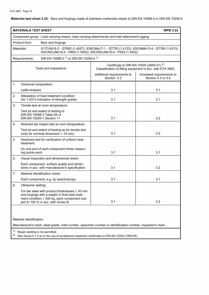
KTA 3903 Page 72
Materials test sheet 3.22: Bars and forgings made of stainless martensitic steels to DIN EN 10088-3 or DIN EN 10250-4
MATERIALS TEST SHEET WPB 3.22
Component group: Load carrying means, load carrying attachments and load attachment rigging
Product form: Bars and forgings
Materials: X17CrNi16-2 - QT800 (1.4057), X39CrMo17-1 - QT750 (1.4122), X3CrNiMo13-4 - QT780 (1.4313), X5CrNiCuNb16-4 - P800 (1.4542), X5CrNiCuNb16-4 - P930 (1.4542)
Requirements: DIN EN 10088-3 1) or DIN EN 10250-4 1)
Tests and inspections
Certificate to DIN EN 10204 (2005-01) 2) Classification of lifting equipment in acc. with KTA 3902:
additional requirements to Section 4.2
increased requirements to Section 4.3 or 4.4
1. Chemical composition:
Ladle analysis
3.1
3.1
2. Attestation of heat treatment condition (for 1.4313 indication of strength grade)
3.1
3.1
3. Tensile test at room temperature:
Test lot and extent of testing to DIN EN 10088-3 Table 26 or DIN EN 10250-1 Section 11
3.1
3.2
4. Notched bar impact test at room temperature:
Test lot and extent of testing as for tensile test (only for nominal dimension ≥ 15 mm)
3.1
3.2
5. Hardness test for verification of uniform heat treatment:
On one end of each component three measur-ing points each
3.1
3.1
6. Visual inspection and dimensional check:
Each component, surface quality and dimen-sions in acc. with manufacturer's specification
3.1
3.2
7. Material identification check:
Each component, e.g. by spectroscopy
3.1
3.1
8. Ultrasonic testing:
For bar steel with product thicknesses ≥ 30 mm and forgings with a weight in final heat treat-ment condition ≥ 300 kg, each component sub-ject to 100 % in acc. with Annex B
3.1
3.2
Material identification:
Manufacturer's mark, steel grade, melt number, specimen number or identification number, inspector's mark
1) Repair welding is not permitted. 2) See clause 5.1.5 as to the use of acceptance inspection certificates to DIN EN 10204 (1995-08).

KTA 3903 Page 73
Materials test sheet 3.23: Bolts and nuts ≤ M 39 to DIN EN ISO 898-1, DIN EN ISO 898-2 and DIN EN ISO 3269
MATERIALS TEST SHEET WPB 3.23
Component group: Load carrying means, load carrying attachments and load attachment rigging
Product form: Bolts and nuts ≤ M 39
Materials: Property classes
Bolts 4.6, 5.6, 6.8, 8.8 and 10.9
Nuts 5, 6, 8 and 10
Requirements: Bolts: DIN EN ISO 898-1, DIN EN ISO 3269, DIN EN 26157-3
(Testing of mechanical properties in accordance with DIN EN ISO 898-1, test series MP1 plus additional re-tempering test in connection with DIN EN 26157-3. Where test series MP1 is not practicable, test series MP2 plus re-tempering test may be performed.)
Nuts: DIN EN ISO 898-2, DIN EN ISO 3269, DIN EN ISO 6157-2
For high-strength bolted joints (10.9): for bolts and nuts additionally DIN EN 14399-4 washers DIN EN 14399-6, DIN 6917 and DIN 6918
Tests and inspections
Certificate to DIN EN 10204 (2005-01) 2) Classification of lifting equipment in acc. with KTA 3902:
additional requirements to Section 4.2
increased requirements to Section 4.3 or 4.4
Proof (by continuous recording in the manufacturer's works) that the requirements regarding mechanical properties, surface condition and dimensional accu-racy have been met
2.2 2) or 3.1 3)
2.2 2) or 3.1 3)
Material identification:
Bolts in acc. with DIN EN ISO 898-1
Nuts in acc. with DIN EN ISO 898-2
1) See clause 5.1.5 as to the use of acceptance inspection certificates to DIN EN 10204 (1995-08).
2) In lieu of the certificate 2.2 stamping will suffice if the manufacturer is recognized in acc. with VdTÜV instruction sheet 1253/4 3) For bolts of property classes 8.8 and 10.9 as well as for nuts of property classes 8 and 10 a certificate 3.1 is required.
Materials test sheet 3.24: Bolts and nuts made of austenitic steels to DIN EN ISO 3506-1, DIN EN ISO 3506-2 and
DIN EN ISO 3269
MATERIALS TEST SHEET WPB 3.24
Component group: Load carrying means, load carrying attachments and load attachment rigging
Product form: Bolts and nuts ≥ M 10 and ≤ M 39
Materials: Property classes 50, 70 and 80
Steel group: A2, A3, A4 and A5
Requirements: DIN EN ISO 3506-1, DIN EN ISO 3506-2, DIN ISO 3269, DIN EN 26157-3, DIN EN ISO 6157-2
Tests and inspections
Certificate to DIN EN 10204 (2005-01) 1) Classification of lifting equipment in acc. with KTA 3902:
additional requirements to Section 4.2
increased requirements to Section 4.3 or 4.4
Proof (by continuous recording in the manufacturer's works) that the requirements regarding mechanical properties, surface condition and dimensional accu-racy have been met
2.2 2)
2.2 2)
Material identification:
In acc. with DIN EN ISO 3506-1, DIN EN ISO 3506-2
1) See clause 5.1.5 as to the use of acceptance inspection certificates to DIN EN 10204 (1995-08). 2) In lieu of the test report stamping will suffice if the manufacturer is recognized in acc. with VdTÜV instruction sheet 1253/4.
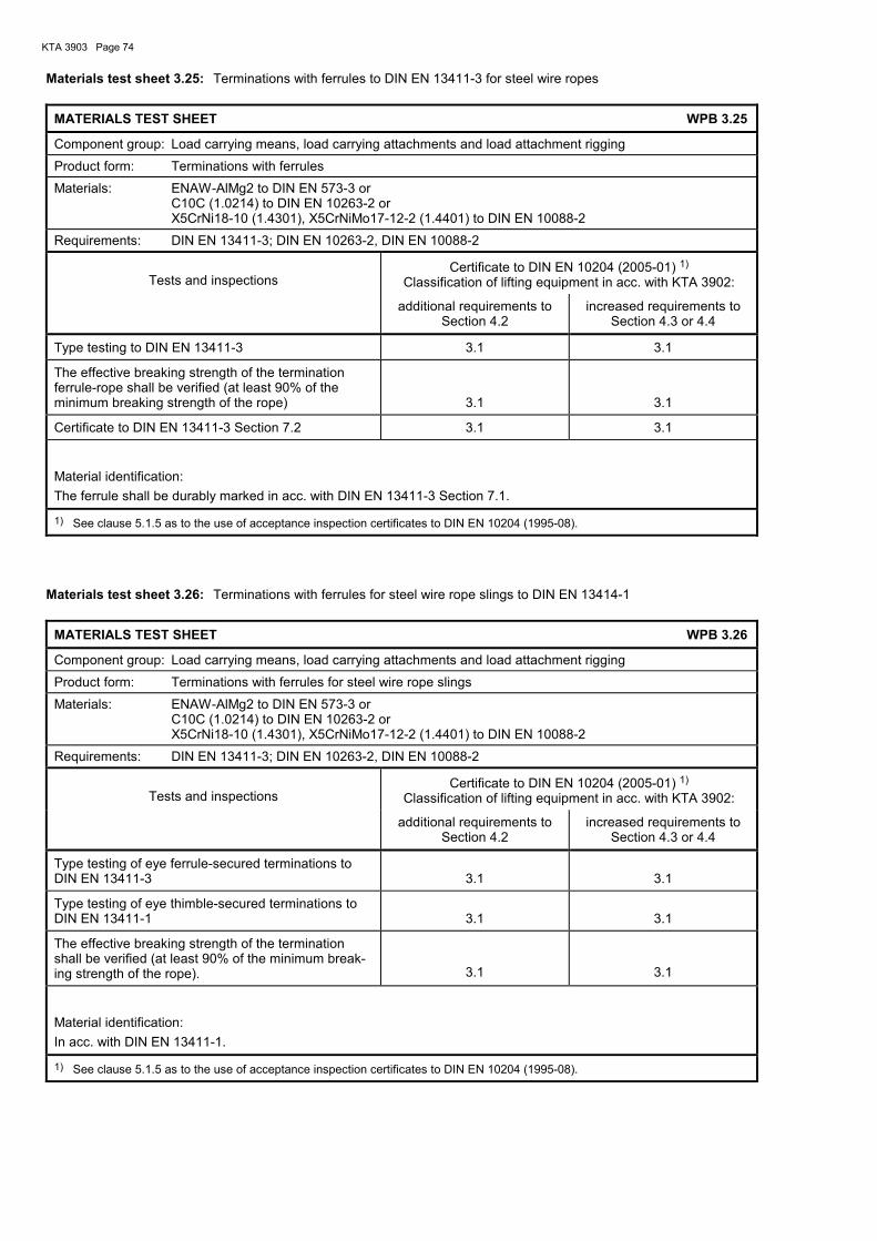
KTA 3903 Page 74
Materials test sheet 3.25: Terminations with ferrules to DIN EN 13411-3 for steel wire ropes
MATERIALS TEST SHEET WPB 3.25
Component group: Load carrying means, load carrying attachments and load attachment rigging
Product form: Terminations with ferrules
Materials: ENAW-AlMg2 to DIN EN 573-3 or C10C (1.0214) to DIN EN 10263-2 or X5CrNi18-10 (1.4301), X5CrNiMo17-12-2 (1.4401) to DIN EN 10088-2
Requirements: DIN EN 13411-3; DIN EN 10263-2, DIN EN 10088-2
Tests and inspections
Certificate to DIN EN 10204 (2005-01) 1) Classification of lifting equipment in acc. with KTA 3902:
additional requirements to Section 4.2
increased requirements to Section 4.3 or 4.4
Type testing to DIN EN 13411-3 3.1 3.1
The effective breaking strength of the termination ferrule-rope shall be verified (at least 90% of the minimum breaking strength of the rope)
3.1
3.1
Certificate to DIN EN 13411-3 Section 7.2 3.1 3.1
Material identification:
The ferrule shall be durably marked in acc. with DIN EN 13411-3 Section 7.1.
1) See clause 5.1.5 as to the use of acceptance inspection certificates to DIN EN 10204 (1995-08).
Materials test sheet 3.26: Terminations with ferrules for steel wire rope slings to DIN EN 13414-1
MATERIALS TEST SHEET WPB 3.26
Component group: Load carrying means, load carrying attachments and load attachment rigging
Product form: Terminations with ferrules for steel wire rope slings
Materials: ENAW-AlMg2 to DIN EN 573-3 or C10C (1.0214) to DIN EN 10263-2 or X5CrNi18-10 (1.4301), X5CrNiMo17-12-2 (1.4401) to DIN EN 10088-2
Requirements: DIN EN 13411-3; DIN EN 10263-2, DIN EN 10088-2
Tests and inspections
Certificate to DIN EN 10204 (2005-01) 1) Classification of lifting equipment in acc. with KTA 3902:
additional requirements to Section 4.2
increased requirements to Section 4.3 or 4.4
Type testing of eye ferrule-secured terminations to DIN EN 13411-3
3.1
3.1
Type testing of eye thimble-secured terminations to DIN EN 13411-1
3.1
3.1
The effective breaking strength of the termination shall be verified (at least 90% of the minimum break-ing strength of the rope).
3.1
3.1
Material identification:
In acc. with DIN EN 13411-1.
1) See clause 5.1.5 as to the use of acceptance inspection certificates to DIN EN 10204 (1995-08).
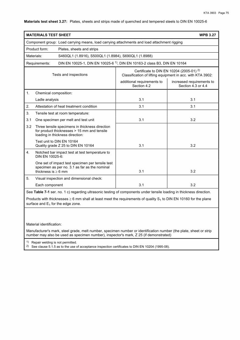
KTA 3903 Page 75
Materials test sheet 3.27: Plates, sheets and strips made of quenched and tempered steels to DIN EN 10025-6
MATERIALS TEST SHEET WPB 3.27
Component group: Load carrying means, load carrying attachments and load attachment rigging
Product form: Plates, sheets and strips
Materials: S460QL1 (1.8916), S500QL1 (1.8984), S690QL1 (1.8988)
Requirements: DIN EN 10025-1, DIN EN 10025-6 1), DIN EN 10163-2 class B3, DIN EN 10164
Tests and inspections
Certificate to DIN EN 10204 (2005-01) 2) Classification of lifting equipment in acc. with KTA 3902:
additional requirements to Section 4.2
increased requirements to Section 4.3 or 4.4
1. Chemical composition:
Ladle analysis
3.1
3.1
2. Attestation of heat treatment condition 3.1 3.1
3. Tensile test at room temperature:
3.1 One specimen per melt and test unit 3.1 3.2
3.2 Three tensile specimens in thickness direction for product thicknesses > 15 mm and tensile loading in thickness direction:
Test unit to DIN EN 10164 Quality grade Z 25 to DIN EN 10164
3.1
3.2
4. Notched bar impact test at test temperature to DIN EN 10025-6:
One set of impact test specimen per tensile test specimen as per no. 3.1 as far as the nominal thickness is ≥ 6 mm
3.1
3.2
5. Visual inspection and dimensional check:
Each component
3.1
3.2
See Table 7-1 ser. no. 1 c) regarding ultrasonic testing of components under tensile loading in thickness direction.
Products with thicknesses ≥ 6 mm shall at least meet the requirements of quality S1 to DIN EN 10160 for the plane surface and E1 for the edge zone.
Material identification:
Manufacturer's mark, steel grade, melt number, specimen number or identification number (the plate, sheet or strip number may also be used as specimen number), inspector's mark, Z 25 (if demonstrated)
1) Repair welding is not permitted. 2) See clause 5.1.5 as to the use of acceptance inspection certificates to DIN EN 10204 (1995-08).

KTA 3903 Page 76
Materials test sheet 4.1: Hot rolled components made of structural carbon steels to DIN EN 10025-2
MATERIALS TEST SHEET WPB 4.1
Component group: Running wheels and their axles and shafts
Product form: Hot rolled components
Materials: Structural carbon steels to DIN EN 10025-2
Requirements: DIN EN 10025-1, DIN EN 10025-2 1)
Tests and inspections
Certificate to DIN EN 10204 (2005-01) 2) Classification of lifting equipment in acc. with KTA 3902:
additional requirements to Section 4.2
increased requirements to Section 4.3 or 4.4
1. Chemical composition:
Ladle analysis
2.2
3.1
2. Attestation of heat treatment condition or of as-delivered condition
2.2
3.1
3. Tensile test at room temperature:
One specimen per melt, test unit and thickness range each
2.2
3.1
4. Notched bar impact test 3) at test temperature to DIN EN 10025-2:
4.1 One test per lot delivered 2.2
4.2 One set of impact test specimen per tensile test specimen as per no. 3 as far as the nominal thickness is ≥ 6 mm
3.1
5. Visual inspection and dimensional check:
Each component
3.1
Material identification:
Manufacturer's mark, steel grade, melt number, specimen number or identification number, inspector's mark; for lifting equipment to KTA 3902, Section 4.2 only manufacturer's mark and steel grade
1) Repair welding is not permitted. 2) See clause 5.1.5 as to the use of acceptance inspection certificates to DIN EN 10204 (1995-08). 3) For qualities J0, J2 and K2 only.

KTA 3903 Page 77
Materials test sheet 4.2: Forged components made of structural carbon steels to DIN EN 10250-2
MATERIALS TEST SHEET WPB 4.2
Component group: Running wheels and their axles and shafts
Product form: Forged components
Materials: S235JRG2 (1.0038), S235J2G3 (1.0116), S355J2G3 (1.0570)
Requirements: DIN EN 10250-1, DIN EN 10250-2 1)
Tests and inspections
Certificate to DIN EN 10204 (2005-01) 2) Classification of lifting equipment in acc. with KTA 3902:
additional requirements to Section 4.2
increased requirements to Section 4.3 or 4.4
1. Chemical composition:
Ladle analysis
3.1
3.1
2. Attestation of heat treatment condition 3.1 3.1
3. Tensile test at room temperature:
One specimen per melt, test unit and thickness range each
3.1
3.1
4. Notched bar impact test at test temperature to DIN EN 10025-2:
One set of impact test specimen per tensile test specimen as far as the nominal thickness is ≥ 15 mm
3.1
3.1
5. Visual inspection and dimensional check:
Each component
3.1
3.1
Material identification:
Manufacturer's mark, steel grade, melt number, specimen number or identification number, inspector's mark; for lifting equipment to KTA 3902 Section 4.2 only manufacturer's mark and steel grade
1) Repair welding is not permitted. 2) See clause 5.1.5 as to the use of acceptance inspection certificates to DIN EN 10204 (1995-08).

KTA 3903 Page 78
Materials test sheet 4.3: Forged or rolled components made of quenched and tempered steels to DIN EN 10083-2, DIN EN 10083-3 or SEW 550
MATERIALS TEST SHEET WPB 4.3
Component group: Running wheels and their axles and shafts
Product form: Forged or rolled components
Materials: Quenched and tempered steels to DIN EN 10083-2, DIN EN 10083-3 or SEW 550
Requirements: DIN EN 10083-1, DIN EN 10083-2 1), DIN EN 10083-3 1) or SEW 550 1)
Tests and inspections
Certificate to DIN EN 10204 (2005-01) 2) Classification of lifting equipment in acc. with KTA 3902:
additional requirements to Section 4.2
increased requirements to Section 4.3 or 4.4
1. Chemical composition:
Ladle analysis
2.2
3.1
2. Attestation of heat treatment condition 2.2 3.1
3. Tensile test at room temperature:
One specimen per melt, dimensional range and heat treatment batch each
2.2
3.1
4. Notched bar impact test at room temperature:
One set of impact test specimens per tensile test specimen, as far as the nominal dimension is ≥ 15 mm
2.2
3.1
5. Visual inspection and dimensional check:
Each component
3.1
6. Materials identification check for alloyed steels:
Each component, e.g. by spectroscopy
3.1
Material identification:
Manufacturer's mark, steel grade, melt number, specimen number or identification number, inspector's mark
1) Repair welding is not permitted. 2) See clause 5.1.5 as to the use of acceptance inspection certificates to DIN EN 10204 (1995-08).

KTA 3903 Page 79
Materials test sheet 4.4: Bright steel made of carbon steels to DIN EN 10277-2, DIN EN 10277-4 or DIN EN 10277-5
MATERIALS TEST SHEET WPB 4.4
Component group: Running wheels and their axles and shafts
Product form: Bright steel
Materials: Carbon steels to DIN EN 10277-2, DIN EN 10277-4 or DIN EN 10277-5
Requirements: DIN EN 10277-1 and DIN EN 10277-2 1), DIN EN 10277-4 1) or DIN EN 10277-5 1)
Tests and inspections
Certificate to DIN EN 10204 (2005-01) 2) Classification of lifting equipment in acc. with KTA 3902:
additional requirements to Section 4.2
increased requirements to Section 4.3 or 4.4
1. Chemical composition:
Ladle analysis
2.2
3.1
2. Attestation of heat treatment condition 2.2 3.1
3. Tensile test at room temperature:
One specimen per melt, dimensional range and heat treatment batch each
2.2
3.1
4. Visual inspection and dimensional check:
Each component
3.1
Material identification:
Manufacturer's mark, steel grade, melt number, specimen number or identification number, inspector's mark; for lifting equipment to KTA 3902 Section 4.2 only manufacturer's mark and steel grade
1) Repair welding is not permitted. 2) See clause 5.1.5 as to the use of acceptance inspection certificates to DIN EN 10204 (1995-08).
Materials test sheet 4.5: Running wheels made of cast steel to DIN EN 10293 or cast steel for pressure vessels to DIN EN 10213
MATERIALS TEST SHEET WPB 4.5
Component group: Running wheels and their axles and shafts
Product form: Running wheels
Materials: Cast steel to DIN EN 10293 or cast steel for pressure vessels to DIN EN 10213
Requirements: DIN EN 10293 or DIN EN 10213
Tests and inspections
Certificate to DIN EN 10204 (2005-01) 1) Classification of lifting equipment in acc. with KTA 3902:
additional requirements to Section 4.2
increased requirements to Section 4.3 or 4.4
1. Chemical composition:
Ladle analysis
3.1
3.1
2. Attestation of heat treatment condition 3.1 3.1
3. Hardness testing on each wheel with conver-sion to tensile strength to DIN EN ISO 18265
3.1
3.1
4. Visual inspection and dimensional check:
Each component
3.1
3.1
Material identification:
Manufacturer's mark, steel grade
1) See clause 5.1.5 as to the use of acceptance inspection certificates to DIN EN 10204 (1995-08).

KTA 3903 Page 80
Materials test sheet 5.1: Brake disks made of spheroidal graphite cast iron to DIN EN 1563
MATERIALS TEST SHEET WPB 5.1
Component group: Other components for hoists
Product form: Brake disks
Materials: Spheroidal graphite cast iron
Requirements: DIN EN 1563
Tests and inspections
Certificate to DIN EN 10204 (2005-01) 2) Classification of lifting equipment in acc. with KTA 3902:
additional requirements to Section 4.2
increased requirements to Section 4.3 or 4.4
1. Chemical composition:
Ladle analysis
3.1
3.1
2. Attestation of heat treatment condition (if heat treatment was performed)
3.1
3.1
3. Tensile test at room temperature:
One specimen per melt treated in same way 2), heat treatment batch (if heat treatment was per-formed) and 2500 kg of similar dimensions each from separately or parallel cast test pieces
3.1
3.1
4. Notched bar impact test at room temperature:
For grades with guaranteed notch toughness one set of specimens per tensile specimen
3.1
3.1
5. Visual inspection and dimensional check:
Each component
3.1
3.1
Material identification:
Manufacturer's mark, steel grade, melt number, specimen number
1) See clause 5.1.5 as to the use of acceptance inspection certificates to DIN EN 10204 (1995-08). 2) Melts treated in same way are melts from the same magnesium treatment batch.

KTA 3903 Page 81
Materials test sheet 5.2: Hot rolled plates and sheets of structural carbon steel to DIN EN 10025-2 for brake drums and brake disks
MATERIALS TEST SHEET WPB 5.2
Component group: Other components for hoists
Product form: brake drums, brake disks
Materials: S235J0 (1.0114), S235J2 (1.0117), S235JR (1.0038), S355J2 (1.0577), S355K2 (1.0596)
Requirements: DIN EN 10025-1, DIN EN 10025-2 1), DIN EN 10164
Tests and inspections
Certificate to DIN EN 10204 (2005-01) 2) Classification of lifting equipment in acc. with KTA 3902:
additional requirements to Section 4.2
increased requirements to Section 4.3 or 4.4
1. Chemical composition:
Ladle analysis
3.1
3.1
2. Attestation of heat treatment condition or of as-delivered condition
3.1
3.1
3. Tensile test at room temperature:
One specimen per melt, test unit and thickness range each
3.1
3.1
4. Notched bar impact test at test temperature to DIN EN 10025-2:
One set of impact test specimen per tensile test specimen as per no. 3 as far as the nominal di-mension is ≥ 6 mm
3.1
3.1
5. Visual inspection and dimensional check:
Each component
3.1
3.1
Material identification:
Manufacturer's mark, steel grade, melt number, specimen number or identification number (the plate or sheet number may also be used as specimen number), inspector's mark
1) Repair welding is not permitted. 2) See clause 5.1.5 as to the use of acceptance inspection certificates to DIN EN 10204 (1995-08).

KTA 3903 Page 82
Annex B
Non-destructive testing (NDT)
Contents
B 1 Scope .................................................................................................................................................... 83
B 2 General specifications .......................................................................................................................... 83
B 2.1 Personnel .............................................................................................................................................. 83
B 2.2 Equipment and test fluids ..................................................................................................................... 83
B 2.3 Requirements for surfaces .................................................................................................................... 83
B 2.4 Point in time of NDT during production test .......................................................................................... 83
B 3 NDT procedural requirements .............................................................................................................. 83
B 3.1 Visual examination ................................................................................................................................ 83
B 3.2 Examination of surfaces by magnetic particle and liquid penetrant methods ....................................... 83
B 3.3 Radiography ......................................................................................................................................... 84
B 3.4 Ultrasonic testing .................................................................................................................................. 84
B 4 Performance and evaluation of tests on ferritic product forms ............................................................ 85
B 4.1 Bars ...................................................................................................................................................... 85
B 4.2 Forged load hooks and load hook nuts................................................................................................. 86
B 4.3 Load hook cross-bars ........................................................................................................................... 88
B 4.4 Shafts and axles for transmissions ....................................................................................................... 88
B 4.5 Transmission casings of series-production electric hoists with rope and of series-production hoist transmissions ............................................................................................................................... 89
B 5 Performance and evaluation of tests on product forms made of austenitic steels (rolled or forged components) ............................................................................................................... 89
B 5.1 Examination of surfaces ....................................................................................................................... 89
B 5.2 Ultrasonic testing .................................................................................................................................. 89
B 6 Performance and evaluation of tests on welds between ferritic steels ................................................. 89
B 6.1 General ................................................................................................................................................. 89
B 6.2 Ultrasonic testing of weld junction areas for plates under tensile loading in thickness direction .......... 89
B 6.3 Visual examination of welds ................................................................................................................. 89
B 6.4 Examination of weld surfaces ............................................................................................................... 90
B 6.5 Radiography of welds ........................................................................................................................... 90
B 6.6 Ultrasonic testing of welds .................................................................................................................... 90
B 7 Performance and evaluation of tests on welds between austenitic steels ........................................... 91
B 7.1 General ................................................................................................................................................. 91
B 7.2 Ultrasonic testing of weld junction areas for plates under tensile loading in thickness direction .......... 91
B 7.3 Visual examination of welds ................................................................................................................. 91
B 7.4 Examination of weld surfaces ............................................................................................................... 91
B 7.5 Radiography on welds .......................................................................................................................... 91

KTA 3903 Page 83
B 1 Scope
(1) This Annex applies to the performance of non-destructive tests and contains procedural requirements and evaluation criteria for non-destructive testing.
(2) Deviations from this Annex may be possible in justified individual cases.
Note: The procedure, extent and point in time of NDT are laid down in material test sheets as well as in in-process test and inspection sequence plans.
B 2 General specifications
B 2.1 Personnel
(1) Test supervisors shall have the technical knowledge required to perform their tasks and know the possibilities of application as well as limits of test procedures. The test su-pervisory personnel
a) in case of production tests, shall have basic knowledge of the fabrication processes used and of the characteristic appearance of fabrication imperfections; they shall nor-mally be independent from the fabrication department and the authorized inspector shall be notified of their names;
b) in case of in-service inspections, shall be familiar with the characteristic features of operationally caused defects.
The test supervisory personnel is responsible for the applica-tion of the test procedure and for the details of the implemen-tation of the test in accordance with the relevant specifica-tions. They are responsible for the employment of qualified and certified NDT operators. This applies also to the employ-ment of personnel not belonging to the works. The test super-visory personnel shall sign the test report.
(2) The test supervisory personnel shall have been qualified and certified for the examination procedures in the relevant product or industrial sectors at least with level 2 to DIN EN 473. For radiographic and ultrasonic testing level 3 qualification and certification is required.
(3) The NDT operators shall have been qualified and certi-fied to DIN EN 473 for the applicable examination procedure in the relevant product or industrial sectors. For radiographic and ultrasonic testing at least level 2 qualification and certifi-cation is required.
B 2.2 Equipment and test fluids
The measuring and testing equipment to be used shall be monitored. The type and intervals of monitoring shall be fixed by the equipment manufacturer with a view to the accuracy of the equipment. The testing of such measuring and testing equipment shall be certified.
B 2.3 Requirements for surfaces
(1) The surfaces shall be free from scale, weld spatters or any other contaminants. Any grooves or notches affecting the test result shall be eliminated.
(2) The arithmetical mean deviation of the assessed profile (average roughness) Ra to DIN EN ISO 4287 shall not exceed
a) 10 µm for examination of surfaces by magnetic particle and liquid penetrant methods,
b) 20 µm for ultrasonic testing on the scanning and opposite surface if it is used as reflection surface.
(3) In the case of waviness of the scanning surfaces for ultrasonic testing the waviness shall be so little as to provide sufficient probe shoe contact. This is generally the case if the distance between probe shoe surface and scanning surface does not exceed 0.5 mm at any point.
(4) Coatings with a thickness up to and including 50 µm are permitted when performing non-destructive examinations, except for the liquid penetrant surface examination method.
(5) Upon completion of the examination the components shall be properly cleaned to remove test liquid residuals.
B 2.4 Point in time of NDT during production test
The product forms shall be tested in the as-delivered condi-tion and welds in the final-heat treatment condition, where possible, and prior to any coating.
B 3 NDT procedural requirements
B 3.1 Visual examination
Visual examinations shall be performed to DIN EN ISO 17637.
B 3.2 Examination of surfaces by magnetic particle and liquid penetrant methods
B 3.2.1 Viewing conditions
(1) The viewing conditions of DIN EN ISO 3059 shall be observed. In addition, the requirements of para. (2) to (6) shall be met:
(2) Where fluorescent detection media are used, the intensi-ty of irradiation of the ultraviolet light on the examination sur-face shall not be less than 10 W/m2. In the case of higher intensity of irradiation a proportionally higher illuminance is admitted on the examination surface in which case the inten-sity of irradiation shall not exceed 50 W/m2.
(3) The eyes of the operator shall have at least 5 minutes to adapt to the light conditions. Photo-chromatic spectacles shall not be used during the examination with ultraviolet radiation.
(4) For the purpose of better detectability of defects suffi-cient contrast shall be provided in magnetic particle examina-tion by the use of suitable media (e.g. fluorescent detection media or application of a thin colour coat only slightly covering the underground). Ultraviolet radiation may additionally be used to improve the contrast in liquid penetrant examination using fluorescent penetrants.
(5) During the examination the angle of viewing shall not deviate by more than 30 degrees from the surface normal. During viewing the distance to the examination surface shall normally be approximately 300 mm.
(6) For the inspection auxiliary means (e.g. magnifying glasses, contrast-improving spectacles, mirrors) are permitted.
B 3.2.2 Magnetic particle testing
B 3.2.2.1 Methods and performance of examination
Magnetic particle examinations shall be performed to DIN EN ISO 9934-1 to meet the following requirements.
B 3.2.2.1.1 Methods
(1) Where magnetisation is achieved in partial areas by the current flow technique or yoke magnetisation, AC magnetisa-tion shall normally be used.
(2) The DC magnetisation method shall only be used upon agreement by the authorized inspector.
(3) The residual magnetic field strength shall not exceed 800 A/m unless a lower value is required. Where the specified value is exceeded, the part shall be demagnetised and the value of the residual magnetic field strength be recorded.

KTA 3903 Page 84
B 3.2.2.1.2 Contact areas in case of current flow technique
(1) Where the examination is performed by current flow technique, consumable electrodes (e.g. lead fin alloys) shall be used, if possible. It shall be ensured that in the contact areas overheating of the material to be examined is avoided.
(2) Where overheating has occurred the overheated areas shall be marked, ground over after the examination and be examined for surface cracks, preferably by a magnetic particle method using yoke magnetisation.
B 3.2.2.1.3 Direction of magnetisation
Each location on the surface shall be examined from two di-rections of magnetisation offset by approximately 90 degrees.
B 3.2.2.1.4 Magnetic field strength Note: a) The magnetic flux in the component surface is decisive for
quality of examination. The required minimum flux density is 1 T. b) Due to technical measuring difficulties to determine the mag-
netic flux in the component, the tangential field strength is usually used as auxiliary variable.
c) The tangential field strength is the tangential component of the magnetic field strength at the test object surface. In low-carbon steels the require flux density of 1T is obtained with a field strength of 2 kA/m
(1) In the case of AC magnetisation the tangential field strength on the surface shall be at least 2 ⋅ 103 A/m and shall not exceed 6.5 ⋅ 103 A/m.
(2) It shall be checked by measurements that these values are adhered to or test conditions shall be determined under which these values may be obtained.
B 3.2.2.1.5 Magnetisation times
The following guide values apply with respect to the applica-tion of the magnetic particles and magnetisation:
a) Magnetisation and application: at least 3 seconds
b) Subsequent magnetisation: at least 5 seconds.
B 3.2.2.2 Inspection medium
(1) According to DIN EN ISO 9943-2 sample-examined media shall be used. Verification of such sample examination shall be submitted to the authorized inspector.
(2) Magnetic particles with a grain size in the range di ex-ceeding 1.5 µm and du less than 30 µm shall be used. De-pending on application, black, fluorescent or coloured pow-ders may be used.
(3) Prior to bathing the surface care shall be taken to ensure that the magnetic powder is distributed uniformly in the vehi-cle fluid and is kept in suspension. Prior to and during the examination the powder suspension shall be spot-checked by suitable pre-magnetised test units (e. g. by reference block 1 to DIN EN ISO 9934-2).
B 3.2.2.3 Test instruments
The test instruments shall meet the requirements of DIN EN ISO 9934-3.
B 3.2.3 Liquid penetrant testing
B 3.2.3.1 Test system
(1) Liquid penetrants shall preferably be used. Fluorescent penetrants or fluorescent dye penetrants may be used.
(2) Solvents or water or both in combination may be used as penetrant remover.
(3) Only wet developers suspended in an aqueous solvent shall be used. Dry developers may only be applied on the scanning surface by electrostatic charging.
(4) For the test system at least the following sensitivity class to DIN EN ISO 3452-2 shall be adhered to:
a) sensitivity class 3 for fluorescent penetrants,
b) sensitivity class 3 for liquid penetrants.
(5) The suitability of the test system (penetrant, solvent remover and developer) shall be demonstrated by means of a sample examination as to DIN EN ISO 3452-2. Verification shall be submitted to the authorized inspector.
(6) Liquid penetrants in test equipment and partly used open tanks (except for aerosol cans) shall be monitored by the user with flux indicator 2 to DIN EN ISO 3452-3. In this test the penetration and development times shall not exceed the times specified for the evaluation. The examination sensi-tivity obtained shall be recorded.
B 3.2.3.2 Performance
(1) Liquid penetrant testing shall be performed in accord-ance with DIN EN 571-1 and the following requirements.
(2) The penetration time shall be at least half an hour.
(3) As soon as possible after drying of the developer, the first inspection should take place. A further inspection shall be performed at the earliest half an hour after the first inspection.
(4) Further points in time of inspection are required if crack-like indications are detected by the second inspection which were not discernible after the first inspection.
Note: Further points in time of inspection may be necessary if during the second inspection essential changes or additional indications are detected.
(5) The evaluation shall be made in due consideration of all inspection results.
B 3.3 Radiography
(1) The radiography of welds shall be performed to DIN EN 1435 class B.
(2) The image quality indicators to DIN EN 462-1 shall be used.
B 3.4 Ultrasonic testing
B 3.4.1 Requirements for test frequencies, transducer (crys-tal) dimension and sound entry positions
The test frequency, transducer dimension and scanning posi-tions are laid down in Sections B 4 to B 6. These specifica-tions are considered guide values from which deviations are possible in justified cases.
B 3.4.2 Performance
B 3.4.2.1 Test instructions
For the ultrasonic testing of
a) parts for which test instructions are required in Section B4, and
b) parts with geometries the examination of which is not covered by Sections B 4 and B 5,
the details shall be laid down in test instructions.

KTA 3903 Page 85
B 3.4.2.2 Setting of sensitivity (examination levels)
The sensitivity shall be set on the test object, on calibration block no. 1 to DIN EN 12223 or on calibration block No. 2 to DIN EN ISO 7963 or on equivalent reference blocks of the same geometry by using suitable reference reflectors. Refer-ence reflectors may be back walls, grooves and boreholes. The reference block dimensions should not differ by more than 10 % from the test piece dimensions.
B 3.4.2.3 Adaptation of the probe to curved surfaces
The probe shall be centred in the probe index area. The dis-tance between the probe base and the test surface should not exceed 0.5 mm at any point. If required, the probe base of angle probes shall be adapted accordingly (see Figure B-1).
Figure B-1: Adaptation of probe base to curved surfaces
B 4 Performance and evaluation of tests on ferritic
product forms
B 4.1 Bars
B 4.1.1 Examination of surfaces
B 4.1.1.1 Performance
(1) The entire surface shall be tested in its finished condi-tion. Magnetic particle testing shall preferably be used.
(2) Magnetic particle testing shall be performed in accord-ance with B 3.2.2. The evaluation shall be made during re-magnetization.
(3) Liquid penetrant testing shall be performed in accord-ance with B 3.2.3.
B 4.1.1.2 Evaluation of magnetic particle test and liquid pen-etrant test
(1) Indications which suggest the presence of crack-like defects are not permitted. Indications with a maximum exten-sion equal to or smaller than 1.5 mm detected by magnetic particle testing and indications equal to or smaller than 3 mm detected by liquid penetrant testing shall not be included in the evaluation. Indications proved to be non-metallic inclu-sions as well as rounded indications up to an extension of 6 mm are permitted.
(2) The frequency of permissible indications shall be locally limited to a number of 5 per square decimetre referred to the entire surface area, but not exceeding 10 per square metre.
(3) In case of greater extension or frequency or in case of systematically occurring discontinuities these locations shall
be repaired or the product’s further usability shall be deter-mined by agreement with the authorized inspector.
B 4.1.2 Ultrasonic testing
B 4.1.2.1 Performance
Section B 3.4 applies to the performance of ultrasonic testing.
B 4.1.2.2 Scanning positions and conditions and evaluation for round bars
(1) The scanning positions for round bars are shown in Figure B-2.
(2) Straight beam scanning shall be effected in positions 1, 2 and 3. For round bars with a diameter d equal to or smaller than 60 mm position 3 will suffice.
(3) The scanning conditions shall be taken from Table B-1.
(4) Where, during straight beam or angle-bream scanning recordable indications of reflectors are detected in the area of lateral wall influence, they shall be verified by means of straight-beam scanning with calibration on a flat bottom hole (diameter 4 mm) with comparable sound path as the indica-tion or by means of purposive angle-beam scanning. The performance of angle-beam scanning shall be laid down in a test instruction.
Where the area of lateral wall influence is omitted due to the cutting into sections of the test object, this condition shall be given priority and be examined anew by straight-beam scan-ning without lateral wall influence.
The results of all examinations shall be covered by the evalu-ation.
(5) The evaluation shall be made in accordance with Table B-2.
Figure B-2: Scanning positions for round bars
B 4.1.2.3 Scanning positions and conditions, evaluation for rectangular or polygonal bars
(1) The scanning positions are shown in Figure B-3.
(2) Straight beam scanning shall be effected in positions 1, 2 and 3, in the latter case, on three paths offset by 120 de-grees (hexagonal bar) or on two paths offset by 90 degrees (rectangular bar). For rectangular or polygonal bars with d equal to or smaller than 60 mm position 3 will suffice.
(3) The scanning conditions shall be taken from Table B-3.
(4) Where, during straight beam or angle-bream scanning recordable indications of reflectors are detected in the area of lateral wall influence, they shall be verified by means of straight-beam scanning with calibration on a flat bottom hole

KTA 3903 Page 86
(diameter 4 mm) with comparable sound path as the indica-tion or by means of purposive angle-beam scanning, the latter being subject to agreement by the authorized inspector.
Where the area of lateral wall influence is omitted due to the cutting into sections of the test object, this condition shall be given priority and be examined anew by straight-beam scan-ning without lateral wall influence.
The results of all examinations shall be covered by the evalu-ation.
(5) The evaluation shall be made in accordance with Table B-4.
Figure B-3: Scanning positions for rectangular or polygonal bars
B 4.2 Forged load hooks and load hook nuts
B 4.2.1 Examination of surfaces
B 4.2.1.1 Performance
(1) The entire surface shall be examined in its finished con-dition. Magnetic particle testing shall be used preferably.
(2) Magnetic particle testing shall be performed in accord-ance with B 3.2.
(3) Liquid penetrant testing shall be performed in accord-ance with B 3.3.
B 4.2.1.2 Evaluation
The evaluation shall be made in accordance with B 4.1.1.2. In addition, the following applies: in the shank area and in the saddle region linear indications transverse to the direction of loading are not permitted.
B 4.2.2 Ultrasonic testing
B 4.2.2.1 Basic material for die-forged single load hooks and load hook nuts
(1) The basic material shall be subjected to straight beam scanning from the outside surface. The evaluation shall be made in accordance with Table B-2 or Table B-4.
(2) The following requirements apply to bars used for nuts:
a) In the case of hexagonal and round bars angle-beam scanning shall be performed over the entire surface area in both circumferential directions with a 35°angle-beam probe.
b) In the case of rectangular bars straight-beam scanning shall be performed over the entire surface area.
c) The scanning positions are shown in Figure B-4 and the scanning conditions are listed in Tables B-1 and B-3.
d) The evaluation of round bars shall be made to Table B-2
and of rectangular or polygonal bars to Table B-4.
Round bars Hexagonal bars Rectangular bars
3
d
6 7 7
d
6
d
Figure B-4: Scanning positions on bars for load hook nuts
B 4.2.2.2 Ramshorn load hook
(1) The scanning positions are shown in Figure B-5.
(2) The evaluation shall be made in accordance with Table B-5.
Figure B-5: Scanning positions for ramshorn load hooks
B 4.2.2.3 Open-die forged single load hooks
Test instructions shall be established in due consideration of para. B 4.2.2.2.

KTA 3903 Page 87
Diameter d, in mm Scanning positions Nominal angle of refraction, degrees
Frequency, MHz
30 < d ≤ 60 3 0 4
60 < d ≤ 120
1 to 3 0 4 4 and 5 70 4
6 and 7 1) 35 4
d > 120
1 and 2 0 4 3 0 2 to 4
4 and 5 70 2 to 4
6 and 7 1) 35 2 to 4
1) Scanning positions 6 and 7 are only applicable to round bars for load hook nuts.
Table B-1: Scanning conditions for round bars
Scanning positions 1 and 2 3 4 and 5 6 and 7
Recording level (diameter of equivalent flat bottom hole deq in mm)
60 < d ≤ 120 : 4 d > 120 : 6
d ≤ 60 : 3 60 < d ≤ 120 : 4
d > 120 : 6
3 2) 3
Permissible excess of the echo amplitude over the recording level, dB
< 6 < 6 < 6 0
Permissible half-amplitude length 1), mm ≤ 10 ≤ d, maximum 50 ≤ 10
Allowable frequency of indication per metre
5 d ≤ 60 : 3 d > 60 : 5
5 0
1) When evaluating the half-amplitude length of reflectors, the probe displacement at a signal amplitude drop of 6 dB to the maximum echo height shall be determined.
2) In the case of contoured probes the distance amplitude correction method (DAC) shall apply; the recording level then is: the echo height of the transverse bore with 3 mm diameter plus a sensitivity allowance of 6 dB.
Table B-2: Evaluation of ultrasonic test on round bars
Lateral dimension d in mm
Scanning positions Nominal angle of refraction, degrees
Frequency, MHz
30 < d ≤ 60 3 0 4
d > 60
1 and 2 0 4 3 0 2 to 4
4 and 5 70 2 to 4
6 and 7 1) 35 2 to 4 1) Scanning positions 6 and 7 are only applicable to polygonal bars for load hook nuts.
Table B-3: Scanning conditions for rectangular or polygonal bars
Scanning positions 1 and 2 3 1) 4 and 5 6 and 7
Recording level (diameter of equivalent flat bottom hole deq in mm)
60 < d ≤ 120 : 4 d > 120 : 6
d ≤ 60 : 3 60 < d ≤ 120 : 4
d > 120 : 6
3
3
Permissible excess of echo amplitude over the recording level, dB
< 6 < 6 < 6 0
Permissible half-amplitude length 2), mm ≤ 10 ≤ d, maximum 50 ≤ 10
Allowable frequency of indication per metre
5 d ≤ 60 : 3 d > 60 : 5
5 0
1) In the case of rectangular bars for load hook nuts the following applies: recording level of circular disk reflector 3, no indications are permit-ted which reach or exceed the recording level.
2) When evaluating the half-amplitude length of reflectors, the probe displacement at a signal amplitude drop of 6 dB to the maximum echo height shall be determined.
Table B-4: Evaluation of ultrasonic test on rectangular or polygonal bars

KTA 3903 Page 88
Scanning positions 1 and 2 3 4 and 5 1) 6 7
Nominal angle of refraction, degrees
0 0 45 0 45
Frequency, MHz 2 or 4 2 or 4 4 2 2
Recording level (diameter of equi-valent flat bottom hole deq in mm) 4 6 4 4 4
Permissible excess of echo ampli-tude over the recording level, dB
< 6 < 6 < 6 0 0
Permissible half-amplitude length 2), mm
≤ 10 ≤ 50 ≤ 10
Allowable frequency of indications per hook
1 3 1 0 0
1) In the case of contoured probes the distance amplitude correction method (DAC) shall apply; the recording level then is: the echo height of the transverse bore with 3 mm diameter plus a sensitivity allowance of 6 dB.
2) When evaluating the half-amplitude length of reflectors, the probe displacement at a signal amplitude drop of 6 dB to the maximum echo height shall be determined.
Table B-5: Evaluation of ultrasonic test on ramshorn load hooks
B 4.3 Load hook cross-bars
B 4.3.1 Examination of surfaces
B 4.3.1.1 Performance
(1) The entire surface shall be examined in its finished con-dition. Magnetic particle testing shall be used preferably.
(2) Magnetic particle testing shall be performed in accord-ance with B 3.2.
(3) Liquid penetrant testing shall be performed in accord-ance with B 3.3.
B 4.3.1.2 Evaluation
The evaluation shall be made in accordance with B 4.1.1.2. Linear indications transverse to the direction of loading are not permitted.
B 4.3.2 Ultrasonic testing
(1) The scanning positions are shown in Figure B-6. The test shall cover the entire volume.
(2) The scanning conditions shall be taken from Table B-6.
(3) The evaluation shall be made in accordance with Table B-7.
3
6
5
6
12
4
2
¢
¢
3¢4¢
1¢
5¢
Figure B-6: Scanning positions for load hook cross-bars
Scanning positions Nominal angle of
refraction, degrees Frequency,
MHz
1, 3, 4, 5 0 4
2 45 2
6 1) 35 2
1) Scanning position 6 or 6′ shall be used if scanning in position 2 or 6′ is not or not entirely possible.
Table B-6: Scanning positions for load hook cross-bars
Scanning positions Straight beam and angled beam
Recording level (diameter of equi-valent flat bottom hole deq in mm)
s ≤ 120 mm: 4 s > 120 mm: 6
Permissible excess of echo ampli-tude over the recording level, dB
< 6
Permissible half-amplitude length 1)
1 x wall thickness, 100 mm at maximum
Allowable frequency of indications
2 indications per m2 of component surface
1) When evaluating the half-amplitude length of reflectors, the probe displacement at a signal amplitude drop of 6 dB to the maximum echo height shall be determined.
Table B-7: Evaluation of ultrasonic test on load hook cross-bars
B 4.4 Shafts and axles for transmissions
B 4.4.1 Examination of surfaces
The examination of surfaces shall be performed and evaluat-ed in accordance with B 4.1.1. In addition, the following ap-plies: linear indications transverse to the direction of loading are not permitted.
B 4.4.2 Ultrasonic testing
B 4.4.2.1 Extent and point in time of testing
The test shall be performed in a state of simple geometry (with plane-parallel or cylindrical surfaces, pre-machined where required) in which case the full volume shall be tested.

KTA 3903 Page 89
B 4.4.2.2 Scanning conditions
(1) The parts shall be tested such that each volumetric area is tested from at least two scanning positions offset by ap-proximately 90 degrees. If this cannot be done by straight beam scanning, angle-beam scanning from two opposite directions shall be performed for each straight-beam scanning omitted.
(2) For rough-turned cylindrical non-stepped shafts and axles the scanning positions of B 4.1.2.2 shall apply.
(3) Figure B-7 shows examples of rough-turned stepped axles and shafts.
(4) Where the scanning conditions of subparas 2 and 3 cannot be applied (e.g. due to specific geometric conditions), test instructions shall be established.
B 4.4.2.3 Evaluation
The evaluation shall be made in accordance with Table B-2.
1
3
3
3
1
1
2
3
23
2
3
3
2
2
′′
′
′
′
′
Figure B-7: Scanning positions for stepped axles and shafts (examples)
B 4.5 Transmission casings of series-production electric hoists with rope and of series-production hoist trans-missions
(1) A surface examination to DIN EN 1371-1 shall be per-formed at machined bearings of transmission casings and be evaluated.
(2) The quality levels SP 3, LP 3, CP 3, AP 3 shall be satisfied.
(3) Indications which suggest the presence of crack-like defects are not permitted.
B 5 Performance and evaluation of tests on product
forms made of austenitic steels (rolled or forged
components)
B 5.1 Examination of surfaces
(1) The entire surface shall be tested in its finished condition.
(2) The tests shall be performed in accordance with B 3.2.1 and B 3.2.3.
(3) The evaluation shall be made in accordance with B 4.1.1.2.
B 5.2 Ultrasonic testing
B 5.2.1 Extent and point in time of testing
The test shall be performed in a state of simple geometry (with plane-parallel or cylindrical surfaces, pre-machined where required) in which case the full volume shall be tested.
B 5.2.2 Determination of testability
(1) For the purpose of determining the test object testability the back wall echoes shall be determined in a grid by straight-beam scanning in wall thickness direction. In areas of non-parallel or non-concentric walls reference echoes shall be used for this test (e.g. bores available, edges or through transmission).
(2) For the area with the largest determinable sound attenu-ation it shall be proved that the required recording levels can be observed.
B 5.2.3 Scanning conditions
The specifications of Section B 4 shall apply to the scanning conditions. The test frequencies shall normally range from 2 MHz to 4 MHz.
B 5.2.4 Performance and Evaluation
The performance and evaluation shall be made in accordance with the specifications of Section B 4. If these criteria cannot be complied with, separate specifications shall be laid down with the authorized inspector.
B 6 Performance and evaluation of tests on welds be-
tween ferritic steels
B 6.1 General
The examination area shall include the weld metal and the adjacent base metal on both sides over a width of
a) 10 mm on each side for wall thicknesses equal to or smaller than 30 mm,
c) 20 mm on each side for wall thicknesses exceeding 30 mm.
B 6.2 Ultrasonic testing of weld junction areas for plates under tensile loading in thickness direction
Ultrasonic testing of the weld junction areas shall be effected in accordance with DIN EN 10160. The examined weld junc-tion areas shall meet the requirements of quality class E4 of DIN EN 10160, Table 5. The test shall be performed with the recording level of circular disk reflector 3.
B 6.3 Visual examination of welds
B 6.3.1 Performance
The visual examination shall be performed to DIN EN ISO 17637.
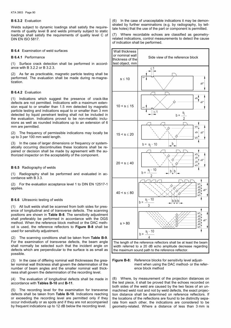
KTA 3903 Page 90
B 6.3.2 Evaluation
Welds subject to dynamic loadings shall satisfy the require-ments of quality level B and welds primarily subject to static loadings shall satisfy the requirements of quality level C of DIN EN ISO 5817.
B 6.4 Examination of weld surfaces
B 6.4.1 Performance
(1) Surface crack detection shall be performed in accord-ance with B 3.2.2 or B 3.2.3.
(2) As far as practicable, magnetic particle testing shall be performed. The evaluation shall be made during re-magne-tization.
B 6.4.2 Evaluation
(1) Indications which suggest the presence of crack-like defects are not permitted. Indications with a maximum exten-sion equal to or smaller than 1.5 mm detected by magnetic particle testing and indications equal to or smaller than 3 mm detected by liquid penetrant testing shall not be included in the evaluation. Indications proved to be non-metallic inclu-sions as well as rounded indications up to an extension of 6 mm are permitted.
(2) The frequency of permissible indications may locally be up to 3 per 100 mm weld length.
(3) In the case of larger dimensions or frequency or system-atically occurring discontinuities these locations shall be re-paired or decision shall be made by agreement with the au-thorized inspector on the acceptability of the component.
B 6.5 Radiography of welds
(1) Radiography shall be performed and evaluated in ac-cordance with B 3.3.
(2) For the evaluation acceptance level 1 to DIN EN 12517-1 applies.
B 6.6 Ultrasonic testing of welds
(1) All butt welds shall be scanned from both sides for pres-ence of longitudinal and of transverse defects. The scanning positions are shown in Table B-8. The sensitivity adjustment shall preferably be performed in accordance with the DGS method. When the reference block method or the DAC meth-od is used, the reference reflectors to Figure B-8 shall be used for sensitivity adjustment.
(2) The scanning conditions shall be taken from Table B-9. For the examination of transverse defects, the beam angle shall normally be selected such that the incident angle on defects which are perpendicular to the surface is as small as possible.
(3) In the case of differing nominal wall thicknesses the grea-ter nominal wall thickness shall govern the determination of the number of beam angles and the smaller nominal wall thick-ness shall govern the determination of the recording level.
(4) The evaluation of longitudinal defects shall be made in accordance with Tables B-10 and B-11.
(5) The recording level for the examination for transverse defects shall be taken from Table B-10. Indications reaching or exceeding the recording level are permitted only if they occur individually or as spots and if they are not accompanied by frequent indications up to 12 dB below the recording level.
(6) In the case of unacceptable indications it may be demon-strated by further examinations (e.g. by radiography, by tell-tale holes) that the use of the part or component is permitted.
(7) Where recordable echoes are classified as geometry-related indications, control measurements to detect the cause of indication shall be performed.
Wall thickness or nominal wall thickness of the test object, mm
Side view of the reference block
s ≤ 10
£
j
1
1
s
10 < s ≤ 15
£ j
j
1 s
2b =
s
b
1
15 < s ≤ 20
j
j
5
bb = s 10
s
5b
20 < s ≤ 40
j
js
b10sb =
bb
b
55
2
40 < s ≤ 80
j
j
10
3
55
bb
bb
b =s b b
s
s > 80
j
j
sb =
4
10
5b
b s
5b
b
The length of the reference reflectors shall be at least the beam width referred to a 20 dB echo amplitude decrease regarding the maximum sound path to the reference reflector.
Figure B-8: Reference blocks for sensitivity level adjust-ment when using the DAC method- or the refer-ence block method
(8) Where, by measurement of the projection distances on the test piece, it shall be proved that the echoes recorded on both sides of the weld are caused by the two faces of an un-machined weld root and not by weld defects, the exact projec-tion distance shall be determined on reference reflectors. If the locations of the reflections are found to be distinctly sepa-rate from each other, the indications are considered to be geometry-related. Where a distance of less than 3 mm is

KTA 3903 Page 91
found, the reflections shall not be treated as separate reflec-tions.
(9) Indications due to geometric discontinuities shall be entered in the test reports with indication of location, position and size.
B 7 Performance and evaluation of tests
on welds between austenitic steels
B 7.1 General
The examination area shall include the weld metal and the adjacent base metal on both sides over a width of
a) 10 mm on each side for wall thicknesses equal to or smaller than 30 mm,
c) 20 mm on each side for wall thicknesses exceeding 30 mm.
B 7.2 Ultrasonic testing of weld junction areas for plates under tensile loading in thickness direction
Ultrasonic testing of the weld junction areas shall be effected in accordance with DIN EN 10307. The examined weld junc-tion areas shall meet the requirements of quality class E4 of DIN EN 10160, Table 5. The test shall be performed with the recording level of circular disk reflector 3.
B 7.3 Visual examination of welds
B 7.3.1 Performance
The visual examination shall be performed to DIN EN ISO 17637.
B 7.3.2 Evaluation
Welds subject to dynamic loadings shall satisfy the require-ments of quality level B and welds primarily subject to static loadings shall satisfy the requirements of quality level C of DIN EN ISO 5817.
B 7.4 Examination of weld surfaces
The examination of surfaces shall be performed and evaluat-ed in accordance with Section B 6.2 using liquid penetrant testing to Section B 3.1.3.
B 7.5 Radiography on welds
(1) Radiography shall be performed and evaluated in ac-cordance with B 3.2.
(2) For the evaluation the requirements of acceptance level 1 to DIN EN 12517-1 apply.

KTA 3903 Page 92
Ser. No.
Accessibility for scanning
Required surface condi-tion of the weld
Scanning positions
1 From both sides of the weld and from one surface at one skip distance
Pos. 2Pos. 1
s
Pos. QF
Test for longitudinal
discontinuities:
Positions 1 and 2 at p 1)
Test for transverse
discontinuities: Position QF at p in the two opposite directions on the weld 2).
2 From both sides of the weld and from both surfaces at ½ skip distance
Test for longitudinal
discontinuities: Positions 1 up to 4 at p/2
Test for transverse
discontinuities: Position QF at p or QF and QF′ at p/2, each in the two opposite direc-tions on the weld 2)
3 From one side of the weld and from both surfaces at one skip distance
Outside and inside machined flat
Test for longitudinal
discontinuities: Positions 1 and 2 at p
Test for transverse
discontinuities: Position QF at p or QF and QF′ at p/2, each in the two opposite direc-tions on the weld
4
From one side of the weld and from one surface at 1 ½ skip distances. If s > 40 mm, second beam angle at one skip distance.
Outside and inside machined flat
Test for longitudinal
discontinuities: Position 1 at 3/2 p
If s ≤ 20 mm position 1 using 60 degrees permitted.
If s > 40 mm position 1 with second angle at p
Test for transverse
discontinuities: Position QF at p in the two opposite directions on the weld
p : skip distance
1) In the case of wall thicknesses > 40 mm, this shall only apply to the smaller beam angle, the evaluation up to P/2 shall be sufficient for the large beam angle.
2) Where the examination for transverse defects is not possible on the weld, the examination may be performed at the base material sur-face adjacent to the weld (in an acute angle as possible to the weld).
Table B-8: Scanning positions for butt welds
Nominal wall thickness s in mm s ≤ 20 20 < s ≤ 40 s > 40
Beam angle, general 70 degrees 60 degrees 45 degrees and 60 degrees
Beam angle in direction of curvature or in the case of wall thickness transitions
45 degrees up to 60 degrees
45 degrees up to 60 degrees
35 degrees up to 45 degrees and
60 degrees up to 70 degrees
Frequency, MHz 4 2 to 4 2 to 4
Table B-9: Scanning conditions for butt welds
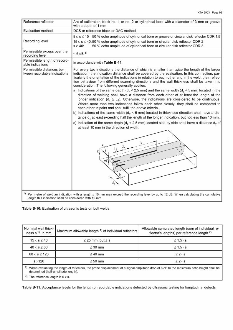
KTA 3903 Page 93
Reference reflector Arc of calibration block no. 1 or no. 2 or cylindrical bore with a diameter of 3 mm or groove with a depth of 1 mm
Evaluation method DGS or reference block or DAC method
Recording level 8 ≤ s ≤ 15 50 % echo amplitude of cylindrical bore or groove or circular disk reflector CDR 1.5
15 ≤ s ≤ 40: 50 % echo amplitude of cylindrical bore or circular disk reflector CDR 2 s > 40: 50 % echo amplitude of cylindrical bore or circular disk reflector CDR 3
Permissible excess over the recording level < 6 dB 1)
Permissible length of record-able indications
in accordance with Table B-11
Permissible distances be-tween recordable indications
For every two indications the distance of which is smaller than twice the length of the larger indication, the indication distance shall be covered by the evaluation. In this connection, par-ticularly the orientation of the indications in relation to each other and in the weld, their reflec-tion behaviour from different scanning directions and the wall thickness shall be taken into consideration. The following generally applies:
a) Indications of the same depth (dz < 2.5 mm) and the same width (dy < 5 mm) located in the direction of welding shall have a distance from each other of at least the length of the longer indication (dx ≥ L2). Otherwise, the indications are considered to be continuous. Where more than two indications follow each other closely, they shall be compared to each other in pairs and shall fulfil the above criteria.
b) Indications of the same width (dy < 5 mm) located in thickness direction shall have a dis-tance dz at least exceeding half the length of the longer indication, but not less than 10 mm.
c) Indication of the same depth (dz < 2.5 mm) located side by side shall have a distance dy of at least 10 mm in the direction of width.
y
1
3
x
2
z
z
xy
d
l
l
dl
d
1) Per metre of weld an indication with a length ≤ 10 mm may exceed the recording level by up to 12 dB. When calculating the cumulative length this indication shall be considered with 10 mm.
Table B-10: Evaluation of ultrasonic tests on butt welds
Nominal wall thick-ness s 1) in mm
Maximum allowable length 1) of individual reflectors Allowable cumulated length (sum of individual re-
flector’s lengths) per reference length 2)
15 < s ≤ 40 ≤ 25 mm, but ≤ s ≤ 1.5 ⋅ s
40 < s ≤ 60 ≤ 30 mm ≤ 1.5 ⋅ s
60 < s ≤ 120 ≤ 40 mm ≤ 2 ⋅ s
s >120 ≤ 50 mm ≤ 2 ⋅ s
1) When evaluating the length of reflectors, the probe displacement at a signal amplitude drop of 6 dB to the maximum echo height shall be determined (half-amplitude length).
2) The reference length is 6 x s.
Table B-11: Acceptance levels for the length of recordable indications detected by ultrasonic testing for longitudinal defects

KTA 3903 Page 94
Annex C
Forms for test records and qualification tests
Form C-1: Test record for transmissions - characteristics and measured data
Form C-2/A: Test record for trial run of transmissions
Form C-2/B: Test record for trial run of transmissions
Form C-3: Qualification test for motor shafts
Form C-4: Qualification test for brakes with or without brake disks - service brake or auxiliary brake (series-production part)
Form C-5: Qualification test for brakes with or without brake disks - safety brake (series-production part)
Form C-6: Qualification test for motor couplings with or without brake disks (series-production part)
Form C-7: Qualification test for drum couplings (series-production part)
Form C-8: Qualification test for rope pulleys (series-production part)
Form C-9: Qualification test for rope end terminations/clamps (series-production part)
Form C-10: Test record for series-production electric hoists with rope
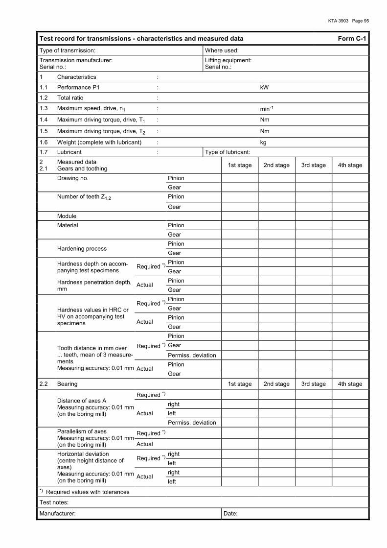
KTA 3903 Page 95
Test record for transmissions - characteristics and measured data Form C-1
Type of transmission: Where used:
Transmission manufacturer: Serial no.:
Lifting equipment: Serial no.:
1 Characteristics :
1.1 Performance P1 : kW
1.2 Total ratio :
1.3 Maximum speed, drive, n1 : min-1
1.4 Maximum driving torque, drive, T1 : Nm
1.5 Maximum driving torque, drive, T2 : Nm
1.6 Weight (complete with lubricant) : kg
1.7 Lubricant : Type of lubricant:
2 2.1
Measured data Gears and toothing
1st stage 2nd stage 3rd stage 4th stage
Drawing no. Pinion
Gear
Number of teeth Z1,2 Pinion
Gear
Module
Material Pinion
Gear
Hardening process
Pinion
Gear
Hardness depth on accom-panying test specimens
Required *) Pinion
Gear
Hardness penetration depth, mm
Actual Pinion
Gear
Required *)
Pinion
Hardness values in HRC or HV on accompanying test specimens
Gear
Actual
Pinion
Gear
Pinion
Tooth distance in mm over ... teeth, mean of 3 measure-ments Measuring accuracy: 0.01 mm
Required *) Gear
Permiss. deviation
Actual
Pinion
Gear
2.2 Bearing 1st stage 2nd stage 3rd stage 4th stage
Distance of axes A Measuring accuracy: 0.01 mm (on the boring mill)
Required *)
right
Actual left
Permiss. deviation
Parallelism of axes Measuring accuracy: 0.01 mm (on the boring mill)
Required *)
Actual
Horizontal deviation (centre height distance of axes) Measuring accuracy: 0.01 mm (on the boring mill)
Required *) right
left
Actual
right
left
*) Required values with tolerances
Test notes:
Manufacturer: Date:

KTA 3903 Page 96
Test record for trial run of transmissions Form C-2 / A
Type of transmission: Design: Where used:
Transmission manufacturer:
Serial no.:
Lifting equipment:
Serial no.:
Recording of contact pattern (tooth bearing) before trial run under no load to Form C-2/B
Transmission speed n1: min-1
Date: Trial run duration, h Load Oil temperature before and after trial run:
°C °C
cckw: ckw: cckw: ckw: Ambient temperature during trial run:
oC
loaded: dB (A)
LA, lm
Noise: 1 : noiseless cckw unloaded: dB (A)
2 : humming ckw loaded: dB (A)
3 : irregular LA, lm
4 : rolling unloaded: dB (A)
Flank clearance: 1st stage 2nd stage 3rd stage 4th stage Remarks
3 measurements on circumference, Measuring accuracy: 0.01 mm
Recording of contact pattern (tooth bearing) after trial run under load to Form C-2/B
Has the transmission been cleared with flushing oil after trial run? yes/no
Are sufficient amounts of oil supplied to the bearings in the case of splash or pressure lubrication? yes/no
Is there any oil flow at the specified bearings in the case of pressure lubrication? yes/no
Is ample amount of lubrication oil supplied to the teeth? yes/no
Leak tightness upon visual inspection? yes/no
Test notes:
Manufacturer: Date:
Authorized inspector to § 20 Atomic Energy Act: Date:
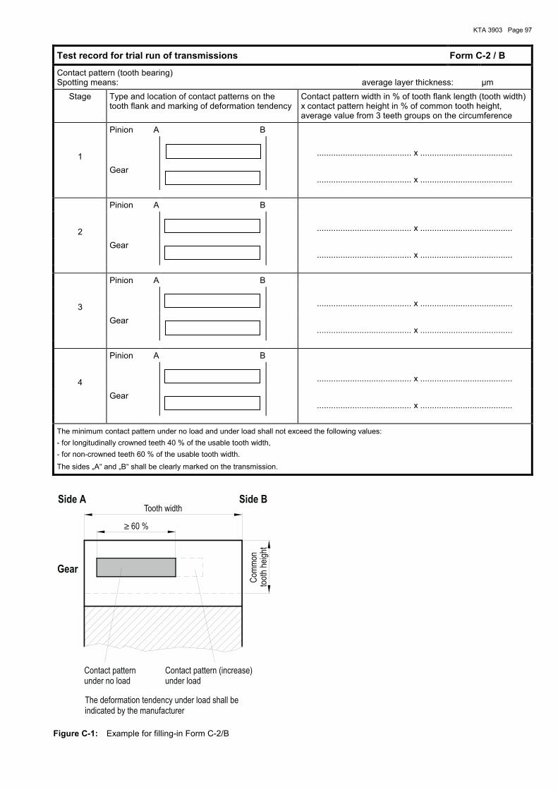
KTA 3903 Page 97
Test record for trial run of transmissions Form C-2 / B
Contact pattern (tooth bearing) Spotting means:
average layer thickness:
µm
Stage Type and location of contact patterns on the tooth flank and marking of deformation tendency
Contact pattern width in % of tooth flank length (tooth width) x contact pattern height in % of common tooth height, average value from 3 teeth groups on the circumference
Pinion A B
1
........................................ x .......................................
Gear
........................................ x .......................................
Pinion A B
2
........................................ x .......................................
Gear
........................................ x .......................................
Pinion A B
3
........................................ x .......................................
Gear
........................................ x .......................................
Pinion A B
4
........................................ x .......................................
Gear
........................................ x .......................................
The minimum contact pattern under no load and under load shall not exceed the following values:
- for longitudinally crowned teeth 40 % of the usable tooth width,
- for non-crowned teeth 60 % of the usable tooth width.
The sides „A“ and „B“ shall be clearly marked on the transmission.
Side B
Gear
Side A
≥
Com
mon
toot
hhe
ight
Contact pattern (increase)under load
The deformation tendency under load shall beindicated by the manufacturer
60 %
Tooth width
Contact patternunder no load
Figure C-1: Example for filling-in Form C-2/B

KTA 3903 Page 98
Qualification test for motor shafts Form C-3
Type/construction of motor
Serial no.
Manufacturer
Type/construction of brake
Serial no.
Manufacturer
Qualification test no., if any
Where used:
Lifting equipment
Serial no.
Nominal speed
Number of operations per hour
Maximum ambient temperature
Maximum humidity
Design data A-side Operational load (lifting)
Operational load (braking)
Assembly load
Special load
Test load
Maximum static torque to KTA 3902
Maximum dynamic torque to KTA 3902
Maximum starting torque of motor
Radial force
Design data B-side Operational load (lifting)
Operational load (braking)
Assembly load
Special load
Test load
Maximum static torque to KTA 3902
Maximum dynamic torque to KTA 3902
Maximum starting torque of motor
Radial force
Confirmation of design data
by the authorized inspector
Manufacturer's motor shaft data
Material
Diameter of shaft end
Design of shaft hub joint
Attestation of qualification by the manufacturer

KTA 3903 Page 99
Qualification test for brakes with or without brake disks
- service brake or auxiliary brake (series-production part) Form C-4
Brake type: Where used (hoist):
Type of brake lifting thrustor:
Brake manufacturer: Lifting equipment:
Serial no.: Serial no.:
1. Design data Operational load
Special load
Assembly load
Test load
Load moment
Maximum moment of inertia of the lifting mass
Maximum moment of inertia of the rotating masses
Minimum safety against load torque 1)
Required braking torque
Nominal speed
Maximum lowering speed at the beginning of braking
Material of the brake disk or drum
Test certificate for brake disk or drum in accordance with ma-terials test sheet
Brake disk or brake drum diameter
Brake disk thickness or brake drum width
Full disk, ventilated disk
Coupling type: make
Dead time until brake response
Operations per hour
Maximum ambient temperature
Maximum humidity
Coefficient of friction at brake lining; static
Coefficient of friction at brake lining; dynamic
Type of brake lining
Confirmation of design data by the authorized inspector:
Date:
2. Qualification test by the manufacturer
Qualification records:
Nominal braking torque:
Maximum braking torque:
Minimum braking torque:
Attestation of qualification by the manufacturer:
Date:
1) See KTA 3902 clause 6.2.1.3.3 (2).
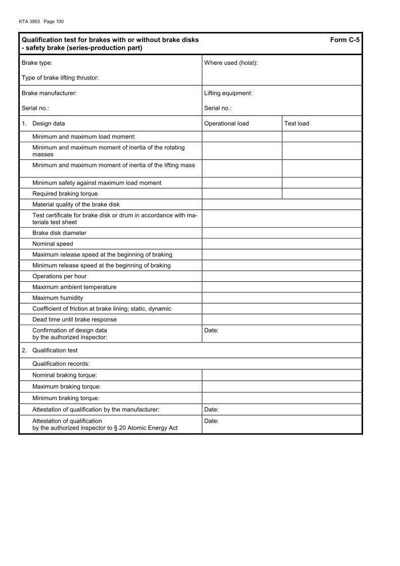
KTA 3903 Page 100
Qualification test for brakes with or without brake disks
- safety brake (series-production part) Form C-5
Brake type: Where used (hoist):
Type of brake lifting thrustor:
Brake manufacturer: Lifting equipment:
Serial no.: Serial no.:
1. Design data Operational load Test load
Minimum and maximum load moment:
Minimum and maximum moment of inertia of the rotating masses
Minimum and maximum moment of inertia of the lifting mass
Minimum safety against maximum load moment
Required braking torque
Material quality of the brake disk
Test certificate for brake disk or drum in accordance with ma-terials test sheet
Brake disk diameter
Nominal speed
Maximum release speed at the beginning of braking
Minimum release speed at the beginning of braking
Operations per hour
Maximum ambient temperature
Maximum humidity
Coefficient of friction at brake lining; static, dynamic
Dead time until brake response
Confirmation of design data by the authorized inspector:
Date:
2. Qualification test
Qualification records:
Nominal braking torque:
Maximum braking torque:
Minimum braking torque:
Attestation of qualification by the manufacturer: Date:
Attestation of qualification by the authorized inspector to § 20 Atomic Energy Act
Date:

KTA 3903 Page 101
Qualification test for motor couplings with or without brake disks (series-production part) Form C-6
Type: Where used:
Brake manufacturer: Lifting equipment:
Serial no.: Serial no.:
1. Design data Operational load
Special load
Assembly load
Test load
Nominal torque of the drive end
Nominal torque of the load end
Transient torque of the load end
Moment of inertia of the drive end
Moment of inertia of the load end
Maximum braking torque
Breakdown torque of the motor
Starting number; operations per hour
Temperature factor
Maximum surface temperature
Maximum speed
Operations per hour
Maximum ambient temperature
Maximum humidity
Material quality of the brake disk or drum
Test certificate for brake disk or drum in accordance with ma-terials test sheet
Confirmation of design data by the authorized inspector
Date:
2. Qualification test
Qualification records:
Attestation of qualification by the manufacturer:
Date:
Qualification test for drum couplings (series-production part) Form C-7
Type: Where used:
Manufacturer: Lifting equipment:
Serial no.: Serial no.:
1. Design data Operational load
Special load
Assembly load
Test load
Maximum design torque in acc. with KTA 3902
Maximum design radial forces
Maximum lowering speed
Maximum nominal speed
Maximum ambient temperature
Material quality
Confirmation of design data by the authorized inspector
Date:
2. Qualification test
Qualification records:
Test notes:
Attestation of qualification by the manufacturer:
Date:

KTA 3903 Page 102
Qualification test for rope pulleys (series-production part) Form C-8
Type: Where used:
Manufacturer: Lifting equipment:
Serial no.: Serial no.:
1. Design data Operational load
Special load
Assembly load
Test load
Maximum rope traction force relevant for design
Maximum nominal speed
Materials of rope coil
Rope diameter
Maximum ambient temperature
Confirmation of design data by the authorized inspector: Date:
2. Qualification test
Qualification records:
Test notes:
Attestation of qualification by the manufacturer: Date:
Qualification test for rope end terminations / clamps (series-production part) Form C-9
Type: Where used:
Manufacturer: Lifting equipment:
Serial no.: Serial no.:
1. Design data Operational load
Special load
Assembly load
Test load
Maximum rope traction force relevant for design
Material quality of rope clamp
Material quality of rope clamp wedge
Rope diameter
Maximum ambient temperature
Safety factors in acc. with DIN 15 020-1
Confirmation of design data by the authorized inspector: Date:
2. Qualification test
Qualification records:
Test notes:
Attestation of qualification by the manufacturer: Date:

KTA 3903 Page 103
Test record for series-production electric hoists with rope Form C-10
Type: Where used:
Load carrying capacity:
Assembly load kg Operational load kg
Manufacturer: For lifting equipment:
Serial no.: Serial no.:
Year built:
Operating voltage: V; Hz Control voltage: V; Hz
Motor data:
Type Serial no. kW V A min-1 % c.d.f.
Main hoist motor
Creep speed hoist motor
Lateral transport motor
Test data of hoist
Main hoist: Load kg V A
Operation at no load
Lifting
Lowering
Operation at nominal load (assembly load or operational load)
Lifting
Lowering
Operation at test load
Lifting
Lowering
Creep speed hoist: Last kg V A
Operation at no load
Lifting
Lowering
Operation at nominal load (assembly load or operational load)
Lifting
Lowering
Operation at test load
Lifting
Lowering
Insulation resistance cold: Main hoist motor MΩ
Creep speed hoist motor MΩ
Test notes:
Manufacturer: Date:
Authorized inspector to § 20 Atomic Energy Act: Date:

KTA 3903 Page 104
Annex D
Tests and inspections of hoist brakes
D 1 General
(1) Regarding the tests and inspections of individual brakes required in accordance with Table 8-1, no. 1.4 and Table 10-1, no. 2.1.5 h, the sequence of precautionary measures de-scribed in D 2 shall apply.
(2) Testing and inspection of safety brakes shall be per-formed in accordance with specific test instructions.
(3) Brakes may alternatively be tested without attached load if a suitable system for determining the braking effect is used and the suitability of the system is verified in accordance with Section D 3.1 for each individual case. In the case of subse-quent retrofitting of the system, testing according to § 25 of BGV D6 will become necessary.
(4) Where a method for determining the braking effect with-out lifting loads is used, the requirements of Section D 3 shall be met regarding the testing of individual brakes to Table 10-1, no. 2.1.5 h) and 2.1.5 i).
D 2 Testing of hoist brakes with load attached
D 2.1 Static brake holding load
The static brake holding load of each individual brake shall be determined:
a) with attached test load in which case each brake aloneshall hold the test load, or
b) with a braking torque measuring system in which case noessential changes shall be ascertained when comparingthe measured values with the calculated values and thevalues determined in foregoing tests.
D 2.2 Braking effect of hoist brakes
(1) The test of the braking effect of hoist brakes with addi-tional requirements to Section 4.2 shall be performed at first with both brakes and then with each individual brake with the test load moving downwards.
(2) The test of the braking effect of hoist brakes with in-creased requirements to Section 4.3 shall be performed at first with all brakes together, then group by group and finally
with each individual brake with the test load moving down-wards.
The following gives an example of the individual test stages for a redundant hoist with 4 brakes (see Figure D-1):
a) Test of all 4 brakes together.
b) Brakes 1 and 2 are lifted. Brakes 3 and 4 are tested to-gether.
c) Brakes 3 and 4 are lifted. Brakes 1 and 2 are tested to-gether.
d) Brakes 2 and 3 are lifted. Brakes 1 and 4 are tested to-gether.
e) Brakes 1 and 4 are lifted. Brakes 2 and 3 are tested to-gether.
f) Brakes 2, 3 and 4 are lifted. Brake 1 is tested.
g) Brakes 1, 2 and 3 are lifted. Brake 4 is tested.
h) Brakes 1, 3 and 4 are lifted. Brake 2 is tested.
i) Brakes 1, 2 and 4 are lifted. Brake 3 is tested.
The braking torque build-up time (from the signal “brake acti-vated“ to the summit of the braking curve) and the braking time (from the summit of the braking curve to standstill) shall be measured, in which case no essential changes shall occur when comparing the measured values with the calculated values and the values obtained in foregoing tests. This ap-plies accordingly to service and auxiliary brakes for hoists with safety brake.
(3) When testing individual brakes care shall be taken to ensure that in the case of failure of the individual brake to be tested all lifted brakes are activated without delay.
D 3 Testing of hoist brakes without load attached
D 3.1 General
(1) Within the scope of the statutory approval and licensing procedure the design approval, final inspection and ac-ceptance testing shall be performed to meet the requirements of Section 5, 7 and 8 of this safety standard.
(2) The measures required for monitoring and maintaining the braking system and test system shall be specified in a service and maintenance manual.
1 Service brake 2 Auxiliary brake 4 Service brake
Drive mechanism 1 Drive mechanism 2
3 Auxiliary brake
Figure D-1: Example for the arrangement of brakes on a redundant hoist

KTA 3903 Page 105
D 3.2 Requirements for the test system and the brakes
(1) The test system shall ensure that
a) during the test without load (lifting mass) the full braking torque can be built up.
b) reactions on the drive mechanisms (including electrical equipment) are avoided. Should this not be possible, the reactions shall be considered in the design of the drive mechanisms and specific design approval documents be established.
c) it is possible to calibrate and test the equipment and re-produce the measured data, and that the equivalence of the tests with or without load is recognizable.
d) the suitability is guaranteed even when considering ambi-ent conditions (e.g. temperature, moisture, dust, condition at intermittent duty).
(2) Within the design approval procedure respective docu-ments for the suitability and design shall be submitted. The suitability of the test system shall be assessed by the author-ized inspector. The crane manufacturer shall confirm that the intended test system has no safety-relevant negative influ-ences on the drive and the hoist. This procedure shall be agreed upon by the technical committee for cranes and eleva-tor at the office of the federal accident insurance corporations responsible for safety and health.
(3) The design of the brakes shall be suited for the test method to be applied in the combined operation of hoist and test system.
(4) The brakes shall meet the requirements of DIN 15434-1 and DIN 15434-2. Their suitability for use in hoists shall be demonstrated by means of Forms C-4 and C-5. In addition, the brake manufacturer or a testing agency shall certify that the requirements of DIN 15 436 have been met in which case the suitability of the brake linings shall be proved on test pieces. The certificate shall state under which condi-tions the frictional material attains stable frictional behav-iour.
D 3.3 Performance of test
The test shall be performed in accordance with test instruc-tions which shall state the total test procedure beginning with a visual inspection of the brakes and the test system (e.g. to determine the general condition, the braking torque setting) up to the checking of the functional capability (by indicating data for the testing of brakes with or without load attached as well as allowable deviations) including a description of the sequence of measuring procedures.
D 3.4 Documentation of the brake test
(1) To fulfil the protective goals of KTA safety standard 3902 and to consider the different conditions of energy distribution in the system with or without load attached, comparable data shall be determined by means of a test with load and a test without load attached, and the following values shall be doc-umented (see Figure D-2):
a) the weight of the load during the test,
b) the nominal torque and direction of rotation of the drive,
c) the point in time of releasing the brake as definite refer-ence point for the whole braking operation; here, it shall be ensured that the drive motor does not generate a counter torque any more,
d) the reaction time of the system consisting of the idle times in the braking system and the time required for braking torque build-up,
e) the excess of the rotation speed,
f) the magnitude of the braking torque attained,
g) the braking time until hoist standstill, where required for the procedure.
(2) Within the course of acceptance testing and after a change of the type of brake linings the reproduceability of the data shall be demonstrated by a sufficient number of braking tests in the entire load range.
(3) The data obtained from the conditions with and without load shall be documented for the first acceptance test, after a change of the type of brake lining and during in-service in-spections (at the latest after 4 years each).
n
n
t
t
Nenn
1
0
b
= nominal r.p.m of the drivemechanism in lowering direction
n1-max
t0tr
t1tb-min
t2-min t2-max
tb-max
n1-min
nNenn
n0
= maximum r.p.m.
= point in time of brake release
= braking time until hoiststandstill
= reaction time up tomaximum r.p.m.
= without load
= with load
t
min
max
r
with load
without load
Figure D-2: Example for a brake diagram with or without load attached

KTA 3903 Page 106
Annex E
Regulations referred to in this Safety Standard
(The references exclusively refer to the version given in this annex. Quotations of regulations referred to therein refer to the version available when the individual reference below was established or issued.)
Directive 2006/42/EC Directive 2006/42/EC of the European Parliament and of the Council of 17 May 2006 on machinery, and amending Directive 95/16/EC (revised edition) (Text with EEA relevance) [OJ L 157, 9.6.2006, pp. 24–86, Corrigendum OJ L 76, 16.3.2007, pp. 35–35]
Directive 92/58/EEC Council Directive 92/58/EEC of 24 June 1992 on the minimum requirements for the provi-sion of safety and/or health signs at work (ninth individual Directive within the meaning of Article 16 (1) of Directive 89/391/EEC) [OJ L 245, 26.8.1992, pp. 23–42]
Directive 95/16/EC European Parliament and Council Directive 95/16/EC of 29 June 1995 on the approximation of the laws of the Member States relating to lifts [OJ L 213, 7.9.1995, p. 1–31]
Atomic Energy Act (AtG) Act on the Peaceful Utilization of Atomic Energy and the Protection against its Hazards (Atomic Energy Act) of December 23, 1959 (BGbl. I, p. 814) as Amended and Promulgated on July 15, 1985 (BGBl. I, p. 1565), last Amendment by article 5 para. 1 of the Law dated 24th February 2012 (BGbl. I, p. 212)
GPSG Law on the rewording of safety provisions for technical work equipment and consumer products (Article 1 Technical work equipment and consumer products act (GPSG)) dated 6th January 2004 (BGBl. I S. 2, p. 219)
StrlSchV Ordinance on the Protection against Damage and Injuries Caused by Ionizing Radiation (Radiation Protection Ordinance) dated 20th July 2001 (BGBl. I 2001, No. 38, p. 1714), last Amendment by article 5 para. 7 of the Law dated 24th February 2012 (BGbl. I, p. 212)
Safety Criteria (1977-10) Safety criteria for nuclear power plants of 21 October 1977 (BAnz. No. 206 of November 3, 1977)
Design Basis (1983-10) Guidelines for the assessment of the design of nuclear power plants with pressurized water Accident Guidelines reactors against design basis accidents as defined in Sec. 28, para. 3 StrlSchV (Design
Basis Accident Guidelines) of October 18, 1983 (Addendum to BAnz. No. 245 of December 31, 1983)
BGG 905 (2004-08) Rules of the federal accident insurance institutions for safety and health at workplace; BG prin-ciples “Inspection and testing of cranes“, October 1996, revised reprinted edition August 2004
BGG 921 (2004-10) Rules of the federal accident insurance institutions for safety and health at workplace; BG prin-ciples “Principles for the selection, training and proof of qualification of crane drivers”, Octo-ber 1996, revised reprint dated October 2004
BGR 500 (2008-04) Rules of the federal accident insurance institutions for safety and health at workplace; BG rules “Operation of working equipment“, January 2005, revised edition April 2008
BGV A3 (2005-01) Rules of the federal accident insurance institutions for safety and health at workplace; BG prescription „Electrical equipment and operating equipment“ dated 1st April 1979 as re-worded 1st January 1997, revised version January 2005
BGV A8 (2002-01) Rules of the federal accident insurance institutions for safety and health at workplace; BG prescription “Safety and health protection marking at workplaces“ dated 1st April 1995 as reworded 1st January 2002
BGV D6 (2000-10) Rules of the federal accident insurance institutions for safety and health at workplace; BG prescription “Cranes“ dated 1st December 1974 as reworded 1st April 2001
BGV D8 (1997-01) Rules of the federal accident insurance institutions for safety and health at workplace; BG prescription “Winches, lifting gear and pulling equipment“ dated 1st April 1980 as reworded 1st January 1997
KTA 1202 (2009-11) Requirements for the Testing Manual
KTA 1401 (1996-06) General Requirements Regarding Quality Assurance
KTA 1404 (2001-06) Documentation during the Construction and Operation of Nuclear Power Plants
KTA 3902 (2012-11) Design of Lifting Equipment in Nuclear Power Plants
DIN EN 81-1 (2010-06) Safety rules for the construction and installation of lifts - Part 1: Electric lifts; German ver-sion EN 81-1:1998+A3:2009
DIN VDE 0105-100 (2009-10) Operation of electrical installations - Part 100: General requirements
DIN EN 462-1 (1994-03) Non-destructive testing; image quality of radiographs; Part 1: image quality indicators (wire type); determination of image quality values; German version EN 462-1:1994
DIN EN 473 (2008-09) General principles for qualification and certification of NDT personnel; German version of EN 473:1992

KTA 3903 Page 107
DIN EN 571-1 (1997-03) Non-destructive testing - Penetrant testing - Part 1: General principles; German version EN 571-1:1997
DIN EN 573-3 (2009-08) Aluminium and aluminium alloys - Chemical composition and form of wrought products - Part 3: Chemical composition and form of products; German version EN 573-3:2009
DIN 685-3 (2001-02) Tested round steel link chains. Part 3: Testing
DIN EN 818-1 (2008-12) Short link chain for lifting purposes - Safety - Part 1: General conditions of acceptance; German version EN 818-1:1996+A1:2008
DIN EN 818-2 (2008-12) Short link chain for lifting purposes - Safety - Part 2: Medium tolerance chain for chain slings; Grade 8; German version of EN 818-2:1996
DIN EN 818-4 (2008-12) Short link chain for lifting purposes - Safety - Part 4: Chain slings - Grade 8; German ver-sion EN 818-4:1996+A1:2008
DIN EN 818-6 (2008-12) Short link chain for lifting purposes - Safety - Part 6: Chain slings - Specification for infor-mation for use and maintenance to be provided by the manufacturer; German version EN 818-6:2000+A1:2008
DIN EN ISO 898-1 (2009-08) Mechanical properties of fasteners made of carbon steel and alloy steel - Part 1: Bolts, screws and studs with specified property classes - Coarse thread and fine pitch thread (ISO 898-1:2009); German version EN ISO 898-1:2009
DIN EN ISO 898-2 (2012-08) Mechanical properties of fasteners made of carbon steel and alloy steel - Part 2: Nuts with spe-cified property classes - Coarse thread and fine pitch thread (ISO 898-2:2012); German version EN ISO 898-2:2012
DIN ISO 965-2 (1999-11) ISO general purpose metric screw threads - Tolerances - Part 2: Limits of sizes for general purpose external and internal screw threads; medium quality (ISO 965-2:1998)
DIN EN 1371-1 (2012-02) Founding - Liquid penetrant testing - Part 1: Sand, gravity die and low pressure die cast-ings; German version EN 1371-1:2011
DIN EN 1435 (2002-09) Non-destructive examination of welds. Radiographic examination of welded joints; German version of EN 1435:1997
DIN EN 1559-2 (2000-04) Founding - Technical conditions of delivery - Part 2: Additional requirements for steel cast-ings; German version EN 1559-2:2000
DIN EN 1563 (2012-03) Founding - Spheroidal graphite cast irons; German version EN 1563:2011
DIN EN 1677-1 (2009-03) Components for slings - Safety - Part 1: Forged steel components, Grade 8; German ver-sion EN 1677-1:2000+A1:2008
DIN EN 1677-2 (2008-06) Components for slings - Safety - Part 2: Forged steel lifting hooks with latch, Grade 8; Ger-man version EN 1677-2:2000+A1:2008 (Corrigendum 2009-01)
DIN EN 1677-3 (2008-06) Components for slings - Safety - Part 3: Forged steel self-locking hooks, Grade 8; German version EN 1677-3:2001+A1:2008 (Corrigendum 2009-01)
DIN EN 1677-4 (2009-03) Components for slings - Safety - Part 4: Links, Grade 8; German version EN 1677-4:2000 +A1:2008
DIN EN ISO 3059 (2002-01) Non-destructive testing - Penetrant testing and magnetic particle testing - Viewing condi-tions (ISO 3059:2001); German version EN ISO 3059:2001
DIN EN ISO 3269 (2000-11) Fasteners - Acceptance inspection (ISO 3269:2000); German version EN ISO 3269:2000
DIN EN ISO 3452-2 (2006-11) Non-destructive testing - Penetrant testing - Part 2: Testing of penetrant materials (ISO 3452-2:2006); German version EN ISO 3452-2:2006
DIN EN ISO 3452-3 (1999-02) Non-destructive testing - Penetrant testing - Part 3: Reference test blocks (ISO 3452-3:1998); German version EN ISO 3452-3:1998
DIN EN ISO 3506-1 (2010-04) Mechanical properties of corrosion-resistant stainless steel fasteners - Part 1: Bolts, screws and studs (ISO 3506-1:2009); German version EN ISO 3506-1:2009
DIN EN ISO 3506-2 (2010-04) Mechanical properties of corrosion-resistant stainless steel fasteners - Part 2: Nuts (ISO 3506-2:2009); German version EN ISO 3506-2:2009
DIN EN ISO 3651-2 (1998-08) Determination of resistance to intergranular corrosion of stainless steels - Part 2: Ferritic, austenitic and ferritic-austenitic (duplex) stainless steels - Corrosion test in media contain-ing sulphuric acid (ISO 3651-2:1998); German version EN ISO 3651-2:1998
DIN 3990-5 (1987-12) Calculation of load capacity of cylindrical gears; endurance limits and material qualities
DIN EN ISO 4287 (2010-07) Geometrical product specification (GPS). Surface texture: Profile method. Terms, definitions and surface texture parameters. (ISO 4287:1997); German version of EN ISO 4287:1998
DIN EN ISO 5817 (2006-10) Welding - Fusion-welded joints in steel, nickel, titanium and their alloys (beam welding excluded) - Quality levels for imperfections (ISO 5817:2003 + Cor. 1:2006); German version EN ISO 5817:2007 (Corrigendum 2007-10)

KTA 3903 Page 108
DIN EN ISO 6157-2 (2004-10) Fasteners - Surface discontinuities - Part 2: Nuts (ISO 6157-2:1995); German version EN ISO 6157-2:2004
DIN 6917 (1989-10) Square taper washers for high-strength structural bolting of steel I sections
DIN 6918 (1990-04) Square taper washers for high-strength structural bolting of steel channel sections
DIN EN ISO 7963 (2010-12) Non-destructive testing - Ultrasonic testing - Specification for calibration block No. 2 (ISO 7963:2006); German version EN ISO 7963:2010
DIN EN ISO 9001 (2008-12) Quality management systems - Requirements (ISO 9001:2008); Trilingual version EN ISO 9001:2008 / Correction 2009-12
DIN EN ISO 9934-1 (2002-03) Non-destructive testing - Magnetic particle testing - Part 1: General principles (ISO 9934-1:2001); German version EN ISO 9934-1:2001
DIN EN ISO 9934-2 (2003-03) Non-destructive testing - Magnetic particle testing - Part 2: Detection media (ISO 9934-2:2002); German version EN ISO 9934-2:2002
DIN EN ISO 9934-3 (2002-10) Non-destructive testing - Magnetic particle testing - Part 3: Equipment (ISO 9934-3:2002); German version EN ISO 9934-3:2002
DIN EN 10025-1 (2005-02) Hot rolled products of structural steels - Part 1: General technical delivery conditions; Ger-man version EN 10025-1:2004
DIN EN 10025-2 (2005-04) Hot rolled products of structural steels - Part 2: Technical delivery conditions for non-alloy structural steels; German version EN 10025-2:2004
DIN EN 10025-6 (2009-08) Hot rolled products of structural steels - Part 6: Technical delivery conditions for flat prod-ucts of high yield strength structural steels in the quenched and tempered condition; Ger-man version EN 10025-6:2004+A1:2009
DIN EN 10028-7 (2008-02) Flat products made of steels for pressure purposes - Part 7: Stainless steels; German ver-sion EN 10028-7:2007
DIN EN 10083-1 (2006-10) Steels for quenching and tempering - Part 1: General technical delivery conditions; German version EN 10083-1:2006
DIN EN 10083-2 (2006-10) Steels for quenching and tempering - Part 2: Technical delivery conditions for non alloy steels; German version EN 10083-2:2006
DIN EN 10083-3 (2007-01) Steels for quenching and tempering - Part 3: Technical delivery conditions for alloy steels; German version EN 10083-3:2006 (Corrigendum 2009-01)
DIN EN 10084 (2008-06) Case hardening steels - Technical delivery conditions; German version EN 10084:2008
DIN EN 10085 (2001-07) Nitriding steels - Technical delivery conditions; German version EN 10085:2001
DIN EN 10088-2 (2005-09) Stainless steels - Part 2: Technical delivery conditions for sheet/plate and strip of corrosion resisting steels for general purposes; German version EN 10088-2:2005
DIN EN 10088-3 (2005-09) Stainless steels - Part 3: Technical delivery conditions for semi-finished products, bars, rods, wire, sections and bright products of corrosion resisting steels for general purposes; German version EN 10088-3:2005
DIN EN 10160 (1999-09) Ultrasonic testing of steel flat product of thickness equal to or greater than 6 mm (reflection method); German version EN 10160:1999
DIN EN 10163-2 (2005-03) Delivery requirements for surface conditions of hot-rolled steel plates, wide flats and sec-tions - Part 2: Plate and wide flats; German version EN 10163-2:2004
DIN EN 10164 (2005-03) Steel products with improved deformation properties perpendicular to the surface of the product - Technical delivery conditions; German version EN 10164:2004
DIN EN 10204 (1995-08) Metallic products - Types of inspection documents (includes Amendment A1:1995); German version EN 10204:1991 + A1:1995
DIN EN 10204 (2005-01) Metallic products - Types of inspection documents; German version EN 10204:2004
DIN EN 10210-1 (2006-07) Hot finished structural hollow sections of non-alloy and fine grain steels - Part 1: Technical delivery conditions; German version EN 10210-1:2006
DIN EN 10213 (2008-01) Steel castings for pressure purposes; German version EN 10213:2007 (Corrigendum 2008-11)
DIN EN 10216-1 (2004-07) Seamless steel tubes for pressure purposes - Technical delivery conditions - Part 1: Non-alloy steel tubes with specified room temperature properties; German version EN 10216-1:2002 + A1:2004
DIN EN 10216-5 (2004-11) Seamless steel tubes for pressure purposes - Technical delivery conditions - Part 5: Stain-less steel tubes; German version EN 10216-5:2004
DIN EN 10217-1 (2005-04) Welded steel tubes for pressure purposes - Technical delivery conditions - Part 1: Non-alloy steel tubes with specified room temperature properties; German version EN 10217-1:2002 + A1:2005

KTA 3903 Page 109
DIN EN 10217-7 (2005-05) Welded steel tubes for pressure purposes - Technical delivery conditions - Part 7: Stainless steel tubes; German version EN 10217-7:2005
DIN EN 10222-1 (2002-07) Steel forgings for pressure purposes - Part 1: General requirements for open die forgings (includes Amendment A1:2002); German version EN 10222-1:1998 + A1:2002
DIN EN 10222-5 (2000-02) Steel forgings for pressure purposes - Part 5: Martensitic, austenitic and austenitic-ferritic stainless steels; German version EN 10222-5:1999
DIN EN 10250-1 (1999-12) Open die steel forgings for general engineering purposes - Part 1: General requirements; German version EN 10250-1:1999
DIN EN 10250-2 (1999-12) Open die steel forgings for general engineering purposes - Part 2: Non-alloy quality and special steels; German version EN 10250-2:1999
DIN EN 10250-4 (2000-02) Open die steel forgings for general engineering purposes - Part 4: Stainless steels; German version EN 10250-4:1999
DIN EN 10263-2 (2002-02) Steel rod, bars and wire for cold heading and cold extrusion - Part 2: Technical delivery conditions for steels not intended for heat treatment after cold working; German version EN 10263-2:2001
DIN EN 10264-1 (2012-03) Steel wire and wire products - Steel wire for ropes - Part 1: General requirements; German version EN 10264-1:2012
DIN EN 10264-3 (2012-03) Steel wire and wire products - Steel wire for ropes - Part 3: Round and shaped non alloyed steel wire for high duty applications; German version EN 10264-3:2012
DIN EN 10264-4 (2012-03) Steel wire and wire products - Steel wire for ropes - Part 4: Stainless steel wire; German version EN 10264-4:2012
DIN EN 10272 (2008-01) Stainless steel bars for pressure purposes; German version EN 10272:2007
DIN EN 10277-1 (2008-06) Bright steel products - Technical delivery conditions - Part 1: General; German version EN 10277-1:2008
DIN EN 10277-2 (2008-06) Bright steel products - Technical delivery conditions - Part 2: Steels for general engineering purposes; German version EN 10277-2:2008
DIN EN 10277-4 (2008-06) Bright steel products - Technical delivery conditions - Part 4: Case-hardening steels; Ger-man version EN 10277-4:2008
DIN EN 10277-5 (2008-06) Bright steel products - Technical delivery conditions - Part 5: Steels for quenching and tem-pering; German version EN 10277-5:2008
DIN EN 10293 (2005-06) Steel castings for general engineering uses; German version EN 10293:2005 (Corrigendum 2008-09)
DIN EN 10307 (2002-03) Non-destructive testing - Ultrasonic testing of austenitic and austenitic-ferritic stainless steels flat products of thickness equal to or greater than 6 mm (reflection method); German version EN 10307:2001
DIN EN 12223 (2000-01) Non-destructive testing - Ultrasonic examination - Specification for calibration block No. 1; German version EN 12223:1999
DIN EN 12385-1 (2009-01) Steel wire ropes - Safety - Part 1: General requirements; German version EN 12385-1:2002+A1:2008
DIN EN 12385-2 (2008-06) Steel wire ropes - Safety - Part 2: Definitions, designation and classification; German ver-sion EN 12385-2:2002+A1:2008 (Corrigendum 2009-01)
DIN EN 12385-4 (2008-06) Steel wire ropes - Safety - Part 2: Definitions, designation and classification; German ver-sion EN 12385-2:2002+A1:2008 (Corrigendum 2009-01)
DIN EN 12517-1 (2006-06) Non-destructive testing of welds - Part 1: Evaluation of welded joints in steel, nickel, titani-um and their alloys by radiography - Acceptance levels; German version EN 12517-1:2006
DIN EN 13018 (2001-07) Non-destructive testing - Visual testing - General principles; German version EN 13018:2001
DIN EN 13411-1 (2009-02) Terminations for steel wire ropes - Safety - Part 1: Thimbles for steel wire rope slings; Ger-man version EN 13411-1:2002+A1:2008
DIN EN 13411-3 (2011-04) Terminations for steel wire ropes - Safety - Part 3: Ferrules and ferrule-securing; German version EN 13411-3:2004+A1:2008
DIN EN 13414-1 (2009-02) Steel wire rope slings - Safety - Part 1: Slings for general lifting service; German version EN 13414-1:2003+A2:2008
DIN EN 13414-2 (2009-02) Steel wire rope slings - Safety - Part 2: Specification for information for use and mainte-nance to be provided by the manufacturer; German version EN 13414-2:2003+A2:2008
DIN EN 13414-3 (2009-02) Steel wire rope slings - Safety - Part 3: Grommets and cable-laid slings; German version EN 13414-3:2003+A1:2008

KTA 3903 Page 110
DIN EN 13557 (2009-07) Cranes - Controls and control stations; German version EN 13557:2003+A2:2008
DIN EN 13586 (2009-05) Cranes - Access; German version EN 13586:2004+A1:2008
DIN EN ISO 13849-1 (2008-12) Safety of machinery - Safety-related parts of control systems - Part 1: General principles for design (ISO 13849-1:2006); German version EN ISO 13849-1:2008
DIN EN 13889 (2009-02) Forged steel shackles for general lifting purposes - Dee shackles and bow shackles - Grade 6 - Safety; German version EN 13889:2003+A1:2008
DIN EN 14399-4 (2006-06) High-strength structural bolting assemblies for preloading - Part 4: System HV - Hexagon bolt and nut assemblies; German version EN 14399-4:2005
DIN EN 14399-6 (2006-06) High-strength structural bolting assemblies for preloading - Part 6: Plain chamfered wash-ers; German version EN 14399-6:2005 + AC:2006
DIN 15003 (1970-02) Lifting Appliances; Load Suspending Devices, Loads and Forces; Definitions
DIN 15018-1 (1984-11) Cranes; steel structures; verification and analyses
DIN 15018-2 (1984-11) Cranes; steel structures; principles of design and construction
DIN 15020-1 (1974-02) Lifting appliances; principles relating to rope drives; calculation and construction
DIN 15020-2 (1974-04) Lifting appliances; principles relating to rope drives; supervision during operation
DIN 15030 (1977-11) Lifting Equipment; Acceptance Testing of Crane Installations; Principles
DIN 15400 (1990-06) Lifting hooks; materials, mechanical properties, lifting capacity and stresses
DIN 15404-1 (1989-12) Lifting hooks; technical delivery conditions for forged hooks
DIN 15405-1 (1979-03) Lifting hooks; inspection of forged hooks in service
DIN 15413 (1983-08) Bottom blocks for lifting appliances; lifting hook nuts
DIN 15434-1 (1989-01) Power transmission engineering; principles for drum- and disc brakes, calculation
DIN 15434-2 (1989-01) Power transmission engineering; principles for drum- and disc brakes; maintenance in service
DIN 15436 (1989-01) Power transmission engineering; drum- and disc brakes; technical requirements for brake linings
DIN EN ISO 15614-1 (2012-06) Specification and qualification of welding procedures for metallic materials - Welding proce-dure test - Part 1: Arc and gas welding of steels and arc welding of nickel and nickel alloys (ISO 15614-1:2004 + Amd 1:2008 + Amd 2:2012); German version EN ISO 15614-1:2004 + A1:2008 + A2:2012
DIN EN ISO 17637 (2011-05) Non-destructive testing of welds - Visual testing of fusion-welded joints (ISO 17637:2003); German version EN ISO 17637:2011
DIN EN ISO 18265 (2004-02) Metallic materials - Conversion of hardness values (ISO 18265:2003); German version EN ISO 18265:2003
DIN 18800-7 (2008-11) Steel structures - Part 7: Execution and constructor's qualification
DIN EN 26157-3 (1991-12) Fasteners; surface discontinuities; bolts, screws and studs subject to special requirements (ISO 6157-3:1988); German version EN 26157-3:1991
DIN EN 60204-32; (2009-03) Safety of machinery - Electrical equipment of machines - Part 32: Requirements for hoisting VDE 0113-32 machines (IEC 60204-32:2008); German version EN 60204-32:2008
DIN VDE 0100-520; (2003-06) Electrical installations of buildings - Part 5: Selection and erection of electrical equipment; VDE 0100-520 Chapter 52: Wiring systems (IEC 60364-5-52:1993, modified); German version HD 384.5.52 S1:1995 + A1:1998 / Correction 2003-08
DIN EN 61000-6-4; (2011-09) Electromagnetic compatibility (EMC) - Part 6-4: Generic standards - Emission standard for VDE 0839-6-4 industrial environments (IEC 61000-6-4:2006 + A1:2010); German version EN 61000-6-4:2007 + A1:2011
DIN IEC 61513; (2002-10) Nuclear power plants - Instrumentation and control for systems important to safety - VDE 0491-2 General requirements for systems (IEC 61513:2001)
DIN EN 61800-3; (2005-07) Adjustable speed electrical power drive systems - Part 3: EMC requirements and specific VDE 0160-103 test methods (IEC 61800-3:2004); German version EN 61800-3:2004
DIN EN 62138; (2010-03) Nuclear power plants - Instrumentation and control important for safety - Software aspects VDE 0491-3-3 for computer-based systems performing category B or C functions (IEC 62138:2004); German version EN 62138:2009
VDI 2194 (2012-08) Selection and training of crane-drivers
VDI 3571 (1977-08) Manufacturing tolerances of bridge cranes carrying-wheel; bearing of carrying wheel and trolley-track

KTA 3903 Page 111
VDI 3576 (2011-03) Rails for crane systems - Rail connections, rail beddings, rail fastenings, tolerances for crane tracks
SEW 550 (1976-08) Steels for larger forgings; quality standards
TRBS 1201-4 (2009-11) Technical Rules for Operational Safety TRBS 1201, Part 4: Inspection of systems liable to supervision – Inspection of elevator systems
VdTÜV MB 1153 (2009-01) Guidelines for the testing, monitoring and certification of welding filler materials
VdTÜV MB 1253/1 Materials; List of material manufacturers recognized by the German technical inspection agency (TÜV)
(the latest edition of this VdTÜV instruction sheet shall be used)
VdTÜV MB 1253/4 List of bolts, screws, studs, and nuts manufacturers (or processing firms) recognized by the German technical inspection agency (TÜV)
(the latest edition of this VdTÜV instruction sheet shall be used)

KTA 3903 Page 112
Annex F (informative)
Changes with respect to the edition 1999-06 and explanations
(1) The requirements of KTA 3902 and KTA 3903 are still based on the standard series DIN 15018, as the European standards intended to form the design basis will have to be established and introduced as an integral standard series with the status of harmonised standards.
(2) Sub-section 1 of the Section “Fundamentals“ was adapted to the formulation uniformly used in all KTA Safety Standards, sub-section 3 was revised editorially and sub-section 5 was put more precisely with respect to the require-ments for quality assurance.
(3) As the requirements for putting into operation laid down in KTA 1401 have also to be observed in the case of lifting equipment with additional or increased requirements, more clearer and precise requirements with reference to KTA 1401 were added (definition of acceptance test in Sections 2.2, 4.2, 5.1.1, 6.1, 8.1).
(4) In Section 5 “Design approval“ the following changes were made:
a) As KTA 3201.3 (2007-11) contains sample forms whichcan also be used for lifting equipment, a correspondingreference was added in Section 5.1.1.
b) Requirements regarding the cover sheet were included(Section 5.1.2).
c) In Section 5.1.3 as well as in Sections 9.3 and 10.2 re-quirements for joints with pre-tensioned bolts were includ-ed which have to be re-assembled upon disassembly. Inclause 5.1.3 new text was added to cover procedures andextent of non-destructive testing on welds as well as onweld-junction areas of components tensile-loaded in thick-ness direction.
d) The requirements for proof of strength were put moreprecisely with respect to the now required qualification testfor motor shafts (Section 5.1.4).
e) In Section 5.1.5 rules for the application of DIN EN 10204,edition 2005-01 were included which make the use of testcertificates possible to both the new edition, (2005-01 -3.2/3.1) and the former edition (1995-08 - 3.1.C/3.1.B).
f) Requirements for test instructions were included (Section5.1.6) which are required for final, acceptance and period-ic inspections.
g) In Section 5.1.8
ga) data sheets for all drive components and operationalmeans
gb) for functions classified into Performance Level c, d or e to KTA 3902, Annex E, a compilation of the intended measures and the pertinent documents for satisfying the requirements of DIN IEC 61513,
gc) a proof of independence of the safety control system from the operational control system
were taken over as design approval document. For RAM programmable systems of these functions documents are required for design approval to satisfy the requirements of DIN EN ISO 13849-1, Section 4.6.3 and DIN EN 62138, Section 6.3.3. In addition, configuration and identification documentation was taken over for these functions. Moreo-ver, the motor diagram, control characteristics for non-controlled drives as well as the motor test record were de-leted since these documents are only required in excep-tional cases.
h) In Section 5.1.10 a new requirement was included that arespective design approval document has to be estab-lished for the ergonomic requirements to KTA 3902, Sec-tion 4.7.
i) In clause 5.1.11 it was pointed out that the test and in-spection sequence plan for final inspection shall be subdi-vided into test and inspections to be performed prior to,during and upon finalization of production and that, in caseof complex tests and inspections, the tests and inspec-tions listed under Table 7-1 shall be subdivided into indi-vidual test and inspection steps in the test and inspectionsequence plan for final inspection.
j) In Section 5.2 the requirements for design approval of elec-trical equipment were put more precisely, since the ob-servance of the respective Performance Level to DIN ENISO 13849-1 will be checked by applying the stipulationslaid down in KTA 3902, Annex E.
(5) Section 6 “Materials“ was supplemented to include re-quirements for the manufacture of materials and for welding consumables and adapted to the current state of standards.
(6) In Section 7 “Final inspection“ the following changes were made:
a) Analogous to the stipulations in other KTA Safety Standardsrequirements regarding manufacture were taken over.
b) The welder’s and welding procedure qualifications laiddown in Section 5.1 were taken over in Section 7.1 andrevise to meet current requirements.
c) Section 7.1, Table 7-1, item 3k), Table 8-1, item 2.6 andTable 10-1, item 3l) further refer to the standard DIN18800-7 withdrawn in 2012-02, since the new Europeanstandards introduced under the building regulations havenot yet been transposed by the manufacturers and a peri-od of co-existence will prevail by 1st July 2014 as regardsthe national standards (among others DIN 18800-7) andthe standard series EN 1090.
d) It was pointed out that for series-production parts andstandardized components the requirements of Section 11shall apply.
e) The documents to be submitted were adapted to the re-quirements of Section 5.1 and rules were taken over re-garding the attendance of the authorized inspector whenultrasonic testing is performed.
f) In addition to the requirements of DIN 15018-1, Table 24,in clauses 7.3 (2) and (3) as well as clauses 12.4.1 (2) and(3) the extent of non-destructive tests on welds was putmore precisely. Here, the stipulations in Table 7-1 for ultra-sonic and radiographic testing of butt welds were taken overfrom Table 7-1 and Table 12-1, respectively, into the textand were adapted to the requirements of Table B-10 withrespect to wall thickness limitations. In addition, the formu-lation found at several locations in Tables 7-1 and 12-1“For all wall thicknesses of austenitic butt welds radiog-raphy shall be used unless a clear test result can be ob-tained by ultrasonic testing“ was replaced by the formula-tion “For all wall thicknesses of austenitic butt welds radi-ography shall be used“, since volumetric ultrasonic exami-nations of austenitic welds do not represent the state-of-the-art.
g) In Sections 7.3 (4), 10.3 (4), B 3.1, B 6.3 and B 7.3 as wellas in Tables 7-1 and 12-1 new requirements for visual ex-aminations were added.
h) The fabrication tolerances of running wheels and theirbearings as well as trolley travelling rails in Table 7-1, no.1i) as well as in Table 12-1, no. 1i) will further be deter-mined in acc. with tolerance category 2 of VDI 3571 sincethe application of VDI 3571 has proved to be effective. VDI3571 was withdrawn in May 2011, however no sufficientexperience is available as regards the application of ISO12488-1 recommended by VDI.

KTA 3903 Page 113
In Table 7-1 ser. no. 3h) was supplemented to require that those areas subject to periodic surface examinations shall also be examined during final inspection.
(7) In Section 8 „Acceptance testing“ the following changes were made:
a) It was pointed out that, upon completion of the acceptance test, the commissioning required to KTA 1401 is complet-ed and the attendance of the authorized inspector was put more precisely.
b) The documents to be submitted and the tests and inspec-tions to be performed in accordance with Table 8-1 were revised in due consideration of the current rules and standards as well as the usual test and inspection se-quences. The examination of the functions classified into Performance Levels a through e to KTA 3902, Annex E, the checking of the user programmable or parameterizable systems as well as checking of electromagnetic compati-bility were taken over as new requirements.
(8) Section 9 was supplemented to include requirements for the organization of transports.
(9) Section 10 “Periodic inspections“ was changed as follows:
a) In Section 10.3 requirements for visual examinations to verify the condition were laid down.
b) In Table 10-1 the inspections of electrical equipment were revised at several locations to adapt to the current more precise requirements regarding acceptance testing.
c) The non-destructive testing requirements in Table 10-1 were changed as follows:
ca) As regards the requirements in ser. no. 3a) and ser. no. 3b) the terms “cracks” and “incipient cracking“ were deleted since here no selected visual examina-tion to Annex B is meant. In connection with the sup-plements made in Section 10.3 it is considered suffi-cient to mention condition monitoring in this table.
cb) Due to the test results obtained, the test interval for the surface examination of the load hook saddle re-gion was adapted to the test interval for the surface examination on the other load suspending devices.
cc) Regarding the requirements in ser. no. 3h), the alter-native examination of the threads by measurement of the backlash in the threaded joint was deleted since measurement of the backlash in the threaded joint does not represent an equivalent substitute for the surface examination of the thread. In addition, it is re-quired to perform “an examination using another non-destructive test method” instead of “ultrasonic testing in accordance with a test and inspection sequence plan”. Here, it is intentionally left open which examina-tion method is to be applied instead of surface exami-nation.
(10) As regards the requirements for series-production parts, standard components as well as series-production electric hoists with rope and series-production hoist transmissions (Sections 11 and 12) the following changes were made:
a) In Sections 11.1 and 12.1 a new requirement was added that the manufacturers of series-production parts as well as series-production electric hoists with rope and series-production hoist transmissions shall have been certified to DIN EN ISO 9001 or shall have a quality management system proved in conformance with the requirements of KTA 1401, section 13.
b) In Section 11.2 shackles are no more mentioned since detailed requirements for shackles were included in KTA 3902, Section 6.4.2.1 and in material test sheet WPB 3.20 of KTA 3903.
c) In Section 12.3 it was laid down that for load-bearing equipment (except for the transmission casings) the tests and inspections required by the material inspection certifi-
cates in Annex A shall be performed. This is to ensure that, in the future, series-production lifting equipment will be subjected to uniform performance of tests and inspec-tions and certification.
d) The requirements in Table 12-1 were put more precisely analogously to the requirements in Table 7-1 and in due consideration of the changes made in Section 12.3. The surface examination of machined bearings of transmission casings was included as new requirement.
(11) The materials test sheets in Annex A were completely revised to adapt to the current state of standards. In many materials test sheets the requirements for non-destructive testing were put more precisely. In addition, the materials test sheets (WPB) were extended to cover several materials not contained up to now, but frequently used. Independently of the classification of the lifting equipment, WPB 1.1 and WPB 1.2 as well as WPB 1.4, 1.5 and 1.6 now require material inspection certificate 3.1 for the materials S235J2 (1.0117), S355J2 (1.0577) and S355K2 (1.0596), P235TR2 (1.0255), P265TR2 (1.0259), S275J2H (1.0138) und S355J2H (1.0576) to conform with DIN 18800-7. The materials test sheet for austenitic cast steel (former WPB 3.17) was deleted as no applications are known. Instead of this WPB the materials test sheet for bolts and studs with thread rolled was taken over from KTA 3905.
(12) Annex B „Non-destructive testing“ was completely re-vised in due consideration of the current state of standards to ensure uniform rules for the performance and evaluation of the tests and inspections. Here care was taken to ensure that uniform terms are used. In its essentials, the following chang-es were made:
a) In Sections B 2, B 3.2 and B 3.3 the requirements were adapted by uniform formulations as regards other KTA Safety Standards (e.g. KTA 3211.1, KTA 3211.3) to the current state of nuclear rules.
b) In Sections B 3.1, B 6.3 and B 7.3 new requirements for visual examinations were added.
c) In Section B 3.4.2.1 the formulation as regards the neces-sity of test instructions was revised due to changes made in other Sections of Annex B.
d) Up to now no stipulations regarding the occurrence of systematic defects had been laid down. In Section B 4.1.1.2, sub-clause 3 a respective requirement was in-cluded, in Section B 6.2.2 the current requirements were supplemented to conform with Section B 4.1.1.2.
e) In Section B 4.2.2.1 as well as in Tables B-1 and B-3 the scanning conditions for bars for load hook nuts in the di-ameter range d ≥ 60 mm (round bars as well as rectangu-lar and polygonal bars) were supplemented to cover scan-ning positions 6 and 7 (scanning in circumferential direc-tion). In addition, specific evaluation levels were defined in Tables B-2 and B-4 (the same as laid down in Table B-5 for ramshorn load hooks).
f) In Section B 4.5 requirements for the examination of transmission casings of series-production electric hoists with rope and series-production hoist transmissions were included.
g) The requirements in Sections B 5.2.2 (new), B 5.2.3 and B 5.2.4 as well as in Tables B-2, B-4, B-5 and B-7 were changed and supplemented such that ultrasonic testing on austenitic product forms is also covered. For austenitic product forms not only straight-beam scanning, but also angle-beam scanning is required to correspond to the state-of-the-art.
h) The ultrasonic testing of butt welds within manufacturing was supplemented to cover an examination for transverse defects (Section B 6.5) thus improving the reliability of the test results. In sub-clauses 6 and 9 the requirements were put more precisely on the basis of the stipulations laid down in KTA 3201.3 (2007-11). In sub-clause 8 it was laid
KTA 3903 Page 114
down that during ultrasonic testing two adjacent indica-tions are to be considered one indication if their distance is less than 3 mm (formerly: less than 2 mm). This regula-tion corresponds to the state-of-the-art. The former sub-clause 10 of Section 6.4.2 (in the wording of 1999-06) was deleted since this requirement is no more necessary due to the changes made in sub-clause 6.
i) At several locations in Annex B the figures were put more precisely and supplemented and the test conditions put more precisely in due consideration of the current stand-ards and quality levels. Among other things, the following was made:
ia) the representation of the reference block for test sen-sitivity adjustment when using the DAC or reference
block method (Figure B-8) was taken over from KTA 3211.3 (2003-11),
ib) the scanning positions (Table B-8) and scanning con-ditions (Table B-9) for butt welds were adapted to comply with the stipulations of KTA 3211.3 (2003-11),
ic) the representation of indications was taken over from DIN EN 1712 into Table B-10.
(13) In Annex C form C-3 “Qualification test for motor shafts“ was included as new form.
(14) At several locations of this safety standard adaptations to the current state of legal prescriptions and standards (espe-cially with regard to material standards) as well as editorial corrections and improvements were made.