Embed Size (px)
Citation preview

INSTALLATION INSTRUCTIONS
KORE TACTICAL SERIES SUSPENSION SYSTEM 2009-2013 Ram 1500 (DS) 4WD PART NUMBER KTS0062
05/10/2012 Page 1 of 41 © 2011, KORE Inc. .All rights reserved.
INTRODUCTION Installation requires a professional mechanic. Prior to beginning, inspect the vehicle’s steering, driveline, and brake sys-tems, paying close attention to the suspension link arms and bushings, stabilizer bars and bushings, tie rod ends, steering rack, ball joints and wheel bearings. Also check the steering and suspension-to-frame attaching points for stress cracks. The overall vehicle must be in excellent working condition; repair or replace all worn parts. Read instructions several times before starting. Be sure you have all the needed parts and know where to install them. Read each step completely as you go. NOTES:
Prior to beginning the installation, check all parts and hardware in the box with the parts listed below. If you find a packaging error, contact KORE directly. Do not contact the dealer where the system was originally pur-chased. You will need the part number when calling: KTS0062.
Front-end realignment is necessary
Do not fabricate any components to gain additional suspension height
Prior to attaching components, be sure all mating surfaces are free of grit, grease, excessive undercoating etc.
A factory service manual should be on hand for reference.
Use the check-off “• ” found at each step to help you keep your place.
Wheel and Tire Recommendations
Note: USE OF AFTERMARKET WHEELS OF THE APPROPRIATE SIZE IS MANDATORY. Using stock wheels with this kit may cause rubbing on control arms and other components. Tire Diameter: 33” to 35” Tire Width: 11.5” to 12.5” Wheel Diameter: 17” Wheel Width: 8” to 8.5” Wheel Back Spacing: For proper clearance and functioning, a wheel 8” to 8.5” wide with a backspace of 4” to 4 3/4” is criti-cal. This is the most common aftermarket wheel size. This size wheel will also increase track width and stability. Lug circle dimension for this vehicle is 5 on 5.5”. We recommended using Procomp wheel (PN# 7028-78585– 8.5” wide w/ backspacing of 4 3/4”) for this installation.

INSTALLATION INSTRUCTIONS
KORE TACTICAL SERIES SUSPENSION SYSTEM 2009-2013 Ram 1500 (DS) 4WD PART NUMBER KTS0062
05/10/2012 Page 2 of 41 © 2011, KORE Inc. .All rights reserved.
PARTS LIST. Identify and check off each part before beginning installation. KTS0062-1
Upper Control Arm, Driver Side 1 94-8179
Lower Control Arm, Driver Side 1 94-7410
CV Axle Extension 1 90-4365 KTS0062-2
Upper Control Arm, Passenger Side 1 94-8182
Lower Control Arm, Passenger Side 1 94-7419
CV Axle Extension 1 90-4365 KTS0062-3
Bucket, Driver Side 1 96-7377
Bucket, Passenger Side 1 96-7385
Bucket Cut Template, Driver Side 1 96-7401
Bucket Cut Template, Passenger Side 1 96-7402
Inner Tie Rod, Driver Side, Small 1 90-4366
Inner Tie Rod, Pass Side, Large 1 90-4384
Adel Clamp 5 90-4383
Hardware Pack, Heater Hose Bracket 1 90-6823
1/4”-20 X 1” Hex Bolt Gr. 8 2 25C100HCS8Y
1/4”-20 Stover Nut Gr. C 2 25CNUCZ
1/4” SAE Flat Washer 4 25NWSAZ
Drill Template, Brake Line Bracket 1 96-7382
Brake Line Bracket 2 94-7394
Description Number Part Number

INSTALLATION INSTRUCTIONS
KORE TACTICAL SERIES SUSPENSION SYSTEM 2009-2013 Ram 1500 (DS) 4WD PART NUMBER KTS0062
05/10/2012 Page 3 of 41 © 2011, KORE Inc. .All rights reserved.
Hardware Pack, 1 90-6824
1/4”-20 X 3/4" Hex Bolt Gr. 8 1 25C075HCS8Y
1/4”-20 Stover Nut Gr. C 1 25CNUCZ
1/4” SAE Flat Washer 2 25NWSAZ
Nut Plate 2 90-7395
Hardware Pack, Brake Line 1 90-6825
3/8”-16 X 1 Hex Bolt Gr. 8 4 37C100HCS8Y
3/8” SAE Flat Washer 4 37NWSAZ
5/16”-18 X 3/4 Hex Bolt Gr. 8 2 31C75HCS8Y
5/16”-18 Stover nut Gr. C 2 31CNUCZ
5/16” Hardened Flat Washer 4 31NWHDY/SAE
Anti-Sway Bar End Link 2 94-8191
Hardware Pack, Anti-Sway Bar End Link 1 90-6826
Bushings 4 45359
Sleeve 4 61150
Hardware Pack, Anti-Sway Bar End Link 1 90-6827
10mm-1.5 X 40mm Hex Bolt 10.9 4 .100C400HCS1Z
10mm Hardened Flat Washer 4 .100NWHDY
1/2" Sway Bar Mount Shim 2 94-7439
Hardware Pack, Anti-Sway Bar End Link 1 90-6828
3/8”-16 X 2 1/2” Hex Bolt Gr. 8 4 37C250HCS8Y
3/8”-16 Stover Nut Gr. C 4 37CNUCZ
3/8” Hardened Flat Washer 8 37NWHDY/SAE
3/8”-16 X 1 1/4” Hex Bolt Gr. 8 2 37C125HCS8Y
3/8”-16 Stover nut Gr. C 2 37CNUCZ
3/8” Hardened Flat Washer 4 37NWHDY/SAE
3/8” USS Hardened Flat Washer 2 37NWHDY/USS
Front Anti-Sway Bar End Link Adapter Bracket Spacer 2 90-2039
Front Anti-Sway Bar End Link Adapter Bracket 2 90-1010
Description Number Part Number

INSTALLATION INSTRUCTIONS
KORE TACTICAL SERIES SUSPENSION SYSTEM 2009-2013 Ram 1500 (DS) 4WD PART NUMBER KTS0062
05/10/2012 Page 4 of 41 © 2011, KORE Inc. .All rights reserved.
Engine Cross Brace 1 94-7403
Hardware Pack, Engine Cross Brace 1 90-6829
1/2”-13 X 4" Hex Bolt Gr. 8 4 50C400HCS8Y
1/2”-13 Stover Nut Gr. C 4 50CNUCZ
1/2” SAE Flat Washer 8 50NWSAZ
Rear Sway Bar Drop, Driver 1 94-7375
Rear Sway Bar Drop, Passenger 1 94-7376
Hardware Pack, Rear Sway Bar drop 1 90-6830
7/16”-14 X 1 1/4” Hex Bolt Gr. 8 2 70-0431251800
7/16”-14 Stover Nut Gr. C 2 72-043100816
7/16” Hardened Flat Washer 4 43NWHDY/SAE
5/16"-18 X 1" Hex Bolt Gr. 8 2 31C100HCS8Y
5/16”-18 Stover Nut Gr. C 2 31CNUCZ
5/16" Hardened Flat Washer 4 31NWHDY/SAE
Large Rear Shock Nut Plate 2 90-7441
Rear Shock Mount, Driver 1 96-7397
Rear Shock Mount, Pass 1 96-7399
Rear Shock Tool 1 96-5545
Hardware Pack, Rear Upper Shock Mount 1 90-6831
5/8”-11 X 5" Hex Bolt Gr. 8 2 62C500HCS8Y
5/8” Hardened Flat Washer 2 62NWHDY/SAE
Hardware Pack, Front Upper Shock Mount 1 90-6832
5/8”-11 X 4" Hex Bolt Gr. 8 2 62C400HCS8Y
5/8”-11 Stover Nut Gr. C 2 62CNUCZ
5/8” Hardened Flat Washer 4 62NWHDY/SAE
Hardware Pack, Front Lower Shock Mount 1 90-6833
5/8”-11 X 3 1/4" Hex Bolt Gr. 8 2 62C325HCS8Y
5/8”-11 Stover Nut Gr. C 2 62CNUCZ
5/8” Hardened Flat Washer 4 62NWHDY/SAE
Description Number Part Number

INSTALLATION INSTRUCTIONS
KORE TACTICAL SERIES SUSPENSION SYSTEM 2009-2013 Ram 1500 (DS) 4WD PART NUMBER KTS0062
05/10/2012 Page 5 of 41 © 2011, KORE Inc. .All rights reserved.
KTS0062-4
Rear Springs 2 52162-1 KTS0062-5
Front Coil Over : Drvr 1 FX6900 (incl. (2) upper 213-01-259-A and (2) lower 213-01-258-A mono ball spacers)
Rear Shock (upper and lower mono ball spacers +4 each) 1 FX6516 (incl. (2) upper 213-18-018-A and (2) lower 213-01-131-A mono ball spacers) KTS0062-6
Front Coil Over : Pass 1 FX6901 (incl. (2) upper 213-01-259-A and (2) lower 213-01-258-A mono ball spacers)
Rear Shock (upper and lower mono ball spacers +2 each) 1 FX6516 (incl. (2) upper 213-18-018-A and (2) lower 213-01-131-A mono ball spacers)
Description Number Part Number

INSTALLATION INSTRUCTIONS
KORE TACTICAL SERIES SUSPENSION SYSTEM 2009-2013 Ram 1500 (DS) 4WD PART NUMBER KTS0062
05/10/2012 Page 6 of 41 © 2011, KORE Inc. .All rights reserved.
FRONT SUSPENSION DISASSEMBLY
Start on the driver’s side of the vehicle.
Work on only one side of the truck at a time.
Lift the truck with jack under the frame.
Support the frame rails with large jack stands.
Remove the front wheels.
Disconnect the negative cable from the battery.
Unclip the factory air box sensor and tube. Undo the inlet clamp and remove the air box. Cover the inlet opening with a
rag. (Image 1)
Image 1
Remove the inner fender liner from the vehicle.
Place a jack under the lower ball joint.
Lift the control arm to compress the front suspension but do not lift the frame off the jack stand.
Have an assistant hold the brakes.

INSTALLATION INSTRUCTIONS
KORE TACTICAL SERIES SUSPENSION SYSTEM 2009-2013 Ram 1500 (DS) 4WD PART NUMBER KTS0062
05/10/2012 Page 7 of 41 © 2011, KORE Inc. .All rights reserved.
Remove the CV axle end nut. Save for reinstallation. (Image 2)
Image 2
Remove the sway bar end link nut, washer and bushing. (Image 3)
Image 3
Unclip the ABS sensor from the fender well, the upper control arm and the brake line.
Unbolt and carefully hang the caliper up out of the work area the remove brake caliper. Secure caliper with zip ties, wire
or tape (Image 4)

INSTALLATION INSTRUCTIONS
KORE TACTICAL SERIES SUSPENSION SYSTEM 2009-2013 Ram 1500 (DS) 4WD PART NUMBER KTS0062
05/10/2012 Page 8 of 41 © 2011, KORE Inc. .All rights reserved.
Image 4
Be careful not to stretch brake line
Remove brake rotor
Image 5
Unbolt the tie rod end stud nut (Image 5)
Use separator or hammer spindle to tie rod end stud. Usually hammering the spindle, adjacent to the stud easily frees
the tie rod end.
Unbolt the brake line from the strut bucket. Carefully, cut a notch in the brake line retainer on the strut bucket and re-
move the brake line. (Image 4) NOTE: Be sure to not cut into the brake line.

INSTALLATION INSTRUCTIONS
KORE TACTICAL SERIES SUSPENSION SYSTEM 2009-2013 Ram 1500 (DS) 4WD PART NUMBER KTS0062
05/10/2012 Page 9 of 41 © 2011, KORE Inc. .All rights reserved.
Hold the upper ball joint stud steady and unbolt the upper ball joint nut. (Image 4)
Image 4
Use a separator or hammer spindle to release the upper ball joint stud. Usually hammering the spindle, adjacent to the
stud easily frees the upper control arm.
Unbolt the upper control arm bolts and flag nuts. Save the OE hardware for reinstallation. (Image 5)
Image 5
Lower the floor jack and remove the upper control arm from the vehicle.

INSTALLATION INSTRUCTIONS
KORE TACTICAL SERIES SUSPENSION SYSTEM 2009-2013 Ram 1500 (DS) 4WD PART NUMBER KTS0062
05/10/2012 Page 10 of 41 © 2011, KORE Inc. .All rights reserved.
Image 6
Unbolt the lower shock mount nut ONLY! from the lower control arm bolt. (Image 6)
Image 7
Make index marks on alignment cams (on lower control arm pivot points) to indicate current alignment
Loosen the lower control arm bolts.
Support the lower control arm with a jack and remove the lower shock bolt. Carefully lower the control arm down while
making sure the outer CV slides out of the bearing hub. (Image 6 & 7)
Loosen and remove the upper strut assembly mounting nuts. (Image 8)

INSTALLATION INSTRUCTIONS
KORE TACTICAL SERIES SUSPENSION SYSTEM 2009-2013 Ram 1500 (DS) 4WD PART NUMBER KTS0062
05/10/2012 Page 11 of 41 © 2011, KORE Inc. .All rights reserved.
Image 8
Remove the strut assembly from the vehicle.
Hold the lower ball joint stud steady and remove the lower ball joint nut. (Image 9)
Image 9
Use a separator or a hammer to release the lower ball joint stud. Usually hammering the spindle, adjacent to the stud
easily frees the lower control arm.

INSTALLATION INSTRUCTIONS
KORE TACTICAL SERIES SUSPENSION SYSTEM 2009-2013 Ram 1500 (DS) 4WD PART NUMBER KTS0062
05/10/2012 Page 12 of 41 © 2011, KORE Inc. .All rights reserved.
Carefully remove the spindle from the vehicle. (Image 10)
Image 10
Unbolt the lower control arm bolts and nuts. Save the OE hardware for reinstallation.
Remove the lower control arm from the vehicle. (Image 11)
Image 11

INSTALLATION INSTRUCTIONS
KORE TACTICAL SERIES SUSPENSION SYSTEM 2009-2013 Ram 1500 (DS) 4WD PART NUMBER KTS0062
05/10/2012 Page 13 of 41 © 2011, KORE Inc. .All rights reserved.
Use a dead blow hammer to dislodge inboard CV joint. (Image 12)
Image 12
Remove the inboard CV from front differential (Image 13)
Image 13
Remove the CV axle from the vehicle. (image 13)
Repeat the preceeding steps on the passenger side of the vehicle.

INSTALLATION INSTRUCTIONS
KORE TACTICAL SERIES SUSPENSION SYSTEM 2009-2013 Ram 1500 (DS) 4WD PART NUMBER KTS0062
05/10/2012 Page 14 of 41 © 2011, KORE Inc. .All rights reserved.
FRONT STRUT TOWER CUTTING AND WELDING
Install the supplied bucket cut template (96-7401 drvr and 96-7402), driver onto the backside of the coil over bucket. Use the front center hole as a guide for proper location and mark the strut bucket for cutting and drilling. (Image 14)
Image 14
Place a heat shield in the engine compartment to protect the engine, hoses and wiring.
Using a cut-off wheel, plasma cutter or other suitable tool cut, off the coil over bucket. Remove the excess from the ve-hicle. Note: Be sure not to cut through any brake lines, fuel lines or wiring. (Image 15)
Image 15

INSTALLATION INSTRUCTIONS
KORE TACTICAL SERIES SUSPENSION SYSTEM 2009-2013 Ram 1500 (DS) 4WD PART NUMBER KTS0062
05/10/2012 Page 15 of 41 © 2011, KORE Inc. .All rights reserved.
Drill out the two hole markings on the front side of the coil over bucket using a 3/4” drill bit. (Image 16)
Image 16
Sand the areas to be welded on the coil over bucket .(Image 17)
Image 17

INSTALLATION INSTRUCTIONS
KORE TACTICAL SERIES SUSPENSION SYSTEM 2009-2013 Ram 1500 (DS) 4WD PART NUMBER KTS0062
05/10/2012 Page 16 of 41 © 2011, KORE Inc. .All rights reserved.
On the passenger side unclip the front heater hoses from the clips. Remove the (2) clips. (Image 18)
Image 18
It is recommended to paint the back and upper areas of the coil over bucket at this time. You will not be able to access these areas after welding.
Set the new coil over mount (96-7377 Drvr and 96-7385 Pass) in place. To assure proper alignment, line up the front hole in the coil over mount and the front hole in the frame. (Image 19) Note: On the passenger side, the heater hose will have to be carefully moved or bent out of the way. On the driver side, the brake lines will have to be careful-ly moved or bent out of the way.
Image 19

INSTALLATION INSTRUCTIONS
KORE TACTICAL SERIES SUSPENSION SYSTEM 2009-2013 Ram 1500 (DS) 4WD PART NUMBER KTS0062
05/10/2012 Page 17 of 41 © 2011, KORE Inc. .All rights reserved.
Clamp the back of the coil over mount (96-7377 Drvr and 96-7385 Pass) to the frame so it sits flat. The coil over mount should sit flat with the front holes still aligned. (Image 20) Note: If the gaps on the sides are too wide, tap the sheet-metal with a hammer to close the gaps.
Image 20
Place a heat shield in the engine compartment prior to welding to protect the engine, wiring and brake lines. Note: Be very careful not to pinch the brake lines with the fitting of the coil over mount.
On both sides, tack weld the coil over mounts (96-7377 Drvr and 96-7385 Pass) to the frame using at least (8) good tack welds. (Image 20)
Starting on the driver side, install engine cross brace (94-7403) to the coil over mounts (96-7377 Dvr and 96-7385 Pass) using the supplied 1/2” X 4” bolts and hardware. (Image 21)
Rosette weld the two holes on the front of the coil over mount. Weld the perimeter of the coil over mount by alternating welding areas to avoid warping the metal. (Image 22)
Once the welds have cooled, remove engine cross brace (94-7403), prime and paint the welded coil over mount areas with a quality paint. (Image 22)
Starting on the driver side, reinstall the engine cross brace (94-7403) using the supplied 1/2” X 4” bolts and hardware. (Image 21)

INSTALLATION INSTRUCTIONS
KORE TACTICAL SERIES SUSPENSION SYSTEM 2009-2013 Ram 1500 (DS) 4WD PART NUMBER KTS0062
05/10/2012 Page 18 of 41 © 2011, KORE Inc. .All rights reserved.
Image 21
Image 22

INSTALLATION INSTRUCTIONS
KORE TACTICAL SERIES SUSPENSION SYSTEM 2009-2013 Ram 1500 (DS) 4WD PART NUMBER KTS0062
05/10/2012 Page 19 of 41 © 2011, KORE Inc. .All rights reserved.
On the passenger side, Secure the OE heater hose to the coil over mount using the supplied (2) Adel clamps (90-4383),
1/4” X 1” bolt and hardware. (Image 23)
On the passenger side, Secure the OE A/C hose to the engine cross brace using the supplied (1) Adel clamp (90-4383),
1/4” X 1” bolt and hardware. (Image 23)
Image 23
Remove the factory inner and outer tie rods. (Image 24)
Image 24

INSTALLATION INSTRUCTIONS
KORE TACTICAL SERIES SUSPENSION SYSTEM 2009-2013 Ram 1500 (DS) 4WD PART NUMBER KTS0062
05/10/2012 Page 20 of 41 © 2011, KORE Inc. .All rights reserved.
FRONT SUSPENSION REASSEMBLY
Install the new inner and outer tie rods (90-4366 Drvr (small) and 90-4384 Pass (large)) with the supplied jam nut and boots. (Image 25) Note: Install the zerk fittings and grease the inner tie rod ends before installing them.. If in-ners needs to be greased in future, remove plastic plug and install zerk fitting. Grease, and re-install plastic plug. IMPORTANT!: Driver side fitting must be taken out before driving vehicle.
Image 25
Reinstall the driver side knuckle onto the lower ball joint. NOTE: The ball joint grease boot should face inboard.
Hold ball stud secure and tighten the lower ball joint nut. Torque to 38 ft. lbs. (Plus an additional 90 degrees) NOTE:
Remove plug and install zerk fitting. Grease, and re-install plug. (Image 26)
Image 26
Carefully measure to find exact center of OE CV axle and cut with chop saw (Image 27)

INSTALLATION INSTRUCTIONS
KORE TACTICAL SERIES SUSPENSION SYSTEM 2009-2013 Ram 1500 (DS) 4WD PART NUMBER KTS0062
05/10/2012 Page 21 of 41 © 2011, KORE Inc. .All rights reserved.
Image 27
Heat CV extension (90-4365) with a torch for 5 minutes (Image 29) and slide CV ends into extension (Image 30)
Image 29
Image 28
Image 30

INSTALLATION INSTRUCTIONS
KORE TACTICAL SERIES SUSPENSION SYSTEM 2009-2013 Ram 1500 (DS) 4WD PART NUMBER KTS0062
05/10/2012 Page 22 of 41 © 2011, KORE Inc. .All rights reserved.
Protect CV boot with a wet rag and plug weld extension to CV axle. (Image 31)
Start weld puddle from axle, not extension. (Image 32) Fill each extension hole entirely with weld. When
finished welding immediately cool area with another wet rag.
Image 31
Image 32

INSTALLATION INSTRUCTIONS
KORE TACTICAL SERIES SUSPENSION SYSTEM 2009-2013 Ram 1500 (DS) 4WD PART NUMBER KTS0062
05/10/2012 Page 23 of 41 © 2011, KORE Inc. .All rights reserved.
First insert the outboard CV splines into wheel bearing. Install the CV axle nut and torque to 100 ft. lbs. (Image 33)
Image 33
Before installing inboard CV, make sure that inboard CV retaining ring is located in groove. This part retains CV on
splined shaft. Chrysler part number (52069710AB, Snap Ring, Axle Shaft).
Install the inner CV shaft (90-4365) to the differential and the lower control arm (94-7410 Drvr and 94-7419 Pass) to the
frame mounts. Secure the new lower control arm using the OE bolts and hardware. The OE nuts remain inboard.
Leave bolts hand tight only at this point. (Image 34) Note: You will know the inner CV joint is seated all the way
when the O-ring can no longer be seen. Sometimes this can require some effort. Use spindle to help leverage
inboard CV into place.
Image 34

INSTALLATION INSTRUCTIONS
KORE TACTICAL SERIES SUSPENSION SYSTEM 2009-2013 Ram 1500 (DS) 4WD PART NUMBER KTS0062
05/10/2012 Page 24 of 41 © 2011, KORE Inc. .All rights reserved.
Support the lower A-Arm assembly with a jack
Install the FOX coil over shock (FX6900 Drvr and FX6901 Pass), mono ball spacers (213-01-259-A) and rubber spacers
(outside of the mono ball spacers) to the upper coil over mount using the supplied 5/8” X 4” bolt and hardware. (Image
35) Note: the reservoirs will be oriented toward the rear of the vehicle.
Image 35
Install the FOX coil over shock (FX6900 Drvr and FX6901 Pass) lower mount, mono ball spacers (213-01-258-A) and
rubber spacers (outside of the mono ball spacers) to the lower control arm mount using the supplied 5/8” X 3 1/4” bolt
and hardware. NOTE: Be sure that the head of the bolt faces toward the rear of the vehicle. (Image 36)
Torque the upper and lower shock bolts to 135 ft./lbs.

INSTALLATION INSTRUCTIONS
KORE TACTICAL SERIES SUSPENSION SYSTEM 2009-2013 Ram 1500 (DS) 4WD PART NUMBER KTS0062
05/10/2012 Page 25 of 41 © 2011, KORE Inc. .All rights reserved.
Image 36
Install new upper control arm (94-8179 Drvr and 94-8182 Pass) using the OE bolts and flag nuts. Flag nuts remain in-
board. Leave bolts hand tight only at this point. (Image 37)
Image 37

INSTALLATION INSTRUCTIONS
KORE TACTICAL SERIES SUSPENSION SYSTEM 2009-2013 Ram 1500 (DS) 4WD PART NUMBER KTS0062
05/10/2012 Page 26 of 41 © 2011, KORE Inc. .All rights reserved.
Reinstall the driver side knuckle onto the upper ball joint.
Hold ball stud secure and tighten upper ball joint nut. Torque to 50 ft. lbs. (Image 38)
Image 38
Unbolt the anti-sway bar frame mounts from the vehicle. (Image 39)
Image 39
Install the 1/2” spacers (94-7439) and re-secure the anti-sway bar frame mounts to the frame using the supplied 10mm
X 40mm bolts and washers. (Image 40)

INSTALLATION INSTRUCTIONS
KORE TACTICAL SERIES SUSPENSION SYSTEM 2009-2013 Ram 1500 (DS) 4WD PART NUMBER KTS0062
05/10/2012 Page 27 of 41 © 2011, KORE Inc. .All rights reserved.
Image 40
Install the anti-sway bar mount bracket (90-1010) to the anti-sway bar using spacer (90-2039), 3/8” x 1 1/4” bolts and
hardware. (Image 41)
Image 41
Assemble the anti-sway bar end links (94-8191) using provided bushings (45359) and sleeves (61150). (Image 42)
Image 42

INSTALLATION INSTRUCTIONS
KORE TACTICAL SERIES SUSPENSION SYSTEM 2009-2013 Ram 1500 (DS) 4WD PART NUMBER KTS0062
05/10/2012 Page 28 of 41 © 2011, KORE Inc. .All rights reserved.
Install the anti-sway bar end links (94-8191) to the sway bar adapter bracket (90-1010) and the lower control arm using
the 3/8” X 2 1/2” bolts and hardware. (Image 43)
Image 43
Pull brake line slack from around the coil over mount. (Image 44) NOTE: On the driver side, remove the line from
the OE clip before repositioning.
Image 44

INSTALLATION INSTRUCTIONS
KORE TACTICAL SERIES SUSPENSION SYSTEM 2009-2013 Ram 1500 (DS) 4WD PART NUMBER KTS0062
05/10/2012 Page 29 of 41 © 2011, KORE Inc. .All rights reserved.
Center the new brake line drill template (96-7382) with the notch facing front, on the window in the frame
Center the brake line drill template on the hole in the frame. Mark and drill (2) 13/32” hole in the frame. (Image 45)
Image 45
Carefully insert the 3/8” nut plate (94-7395) into the opening on the backside of the frame. (Image 46) Note: Paint the
frame prior to installing the brake line bracket (94-7394).
Image 46
Install the brake line bracket (94-7394) to the (2) newly drilled holes in the frame using the supplied nut plate (94-7395)
3/8” X 1” bolts and hardware. (Image 47)

INSTALLATION INSTRUCTIONS
KORE TACTICAL SERIES SUSPENSION SYSTEM 2009-2013 Ram 1500 (DS) 4WD PART NUMBER KTS0062
05/10/2012 Page 30 of 41 © 2011, KORE Inc. .All rights reserved.
Image 47
Secure the brake line to the new mount using the supplied 5/16” X 3/4” bolts and hardware (Image 48) Note: Be sure
the metal brake lines do not contact anything (frame, arms, etc…)
Image 48
Reinstall brake rotor and caliper. Tighten bolts to 130 ft. lbs.
Route the ABS line up the spindle and through the upper control arm. Zip tie clear of any moving parts
Cycle steering lock to lock. Check all components for proper operation and clearances. Pay special attention to the
clearance between the brake hoses and wiring

INSTALLATION INSTRUCTIONS
KORE TACTICAL SERIES SUSPENSION SYSTEM 2009-2013 Ram 1500 (DS) 4WD PART NUMBER KTS0062
05/10/2012 Page 31 of 41 © 2011, KORE Inc. .All rights reserved.
Reinstall the tie rod end (90-4366 Drvr and 90-4384 Pass) stud to the spindle.
Hold ball stud secure and tighten the tie rod end nut. Torque to 50 ft. lbs. (Image 49)
Image 49
Remove the jack from under the lower control arm
Grease all grease fittings (ball joints, tie rods, etc…)
Reinstall the front wheels. Using a criss-cross pattern, tighten the lug nuts to 130 ft. lbs.
With wheels off the floor so that suspension “droops” out all the way. Cycle steering lock to lock. Check all components
for proper operation and clearances. Pay special attention to the clearance between the tires/wheels and spindles,
brake hoses, wiring etc.
Repeat the procedure on passenger side of the vehicle.
Jack up the vehicle, remove the jack stands and lower the vehicle to the ground.
Index the alignment cams with marks you made and tighten the lower control arm bolts to 150 ft. lbs.
Tighten the upper control arm bolts to 130 ft. lbs.
Remove rag and reinstall the factory air box, tube and wiring clip using the previously removed OE clamp. (Image 50)

INSTALLATION INSTRUCTIONS
KORE TACTICAL SERIES SUSPENSION SYSTEM 2009-2013 Ram 1500 (DS) 4WD PART NUMBER KTS0062
05/10/2012 Page 32 of 41 © 2011, KORE Inc. .All rights reserved.
Image 50
Have truck professionally aligned immediately.
NOTE: When you have truck aligned, have alignment professional loosen all four lower control arm bolts all the
way. Then align truck. The lower control arm bushings are designed to twist and must be set in a neutral state
from the static position. A precise alignment, including the centering of the steering wheel, is required in order
for the vehicle’s Electronic Stability Program to function properly. A laser alignment is recommended.
Adjust headlights.

INSTALLATION INSTRUCTIONS
KORE TACTICAL SERIES SUSPENSION SYSTEM 2009-2013 Ram 1500 (DS) 4WD PART NUMBER KTS0062
05/10/2012 Page 33 of 41 © 2011, KORE Inc. .All rights reserved.
REAR SUSPENSION DISASSEMBLY
Start with working on the driver side of the vehicle.
Work on only one side of the truck at a time.
Lift the truck with a jack under the frame.
Support the frame rails with large jack stands.
Unbolt and remove the rear wheels.
Remove the tailgate from the vehicle.
Unbolt and remove the rear bumper from the vehicle. Save the hardware for reinstallation. (Image 51)
Image 51
Remove the OE rear inner fender liner from the vehicle. (Image 52)
Image 52

INSTALLATION INSTRUCTIONS
KORE TACTICAL SERIES SUSPENSION SYSTEM 2009-2013 Ram 1500 (DS) 4WD PART NUMBER KTS0062
05/10/2012 Page 34 of 41 © 2011, KORE Inc. .All rights reserved.
Remove the OE bed support bracket from the front side of the rear fender opening. (Image 53)
Image 53
Carefully unbolt and pull out the taillights from the rear fenders. Save hardware for reinstallation. (Image 54)
Image 54
Unplug the tail light wiring harness and remove them from the vehicle.

INSTALLATION INSTRUCTIONS
KORE TACTICAL SERIES SUSPENSION SYSTEM 2009-2013 Ram 1500 (DS) 4WD PART NUMBER KTS0062
05/10/2012 Page 35 of 41 © 2011, KORE Inc. .All rights reserved.
Unbolt the fuel filler neck from the rear fender. Remove the filler neck from the fender fuel filling hole in the fender.
Save the hardware for reinstallation. (Image 55) Important!: Be sure to leave the gas cap on the filler neck once
the bed is removed. This will keep the fumes from escaping the tank.
Image 55
Unbolt the (6) OE bolts that attach the rear bed to the frame of the vehicle. Save hardware for reinstallation.
Using a lift or group of people, carefully remove the bed from the vehicle. (Image 56) NOTE: Be sure to unplug all rear
bed wiring harnesses before removing the bed from the vehicle.
Image 56

INSTALLATION INSTRUCTIONS
KORE TACTICAL SERIES SUSPENSION SYSTEM 2009-2013 Ram 1500 (DS) 4WD PART NUMBER KTS0062
05/10/2012 Page 36 of 41 © 2011, KORE Inc. .All rights reserved.
Unbolt and remove the rear OE shock from the vehicle. (Image 57) NOTE: It may be necessary that you slightly
raise the axle to unload the shocks for removal.
Image 57
Unbolt the OE upper sway bar end link hardware. Save for reinstallation. (Image 58)
Image 58
Unbolt the brake line and ABS line from frame rail.

INSTALLATION INSTRUCTIONS
KORE TACTICAL SERIES SUSPENSION SYSTEM 2009-2013 Ram 1500 (DS) 4WD PART NUMBER KTS0062
05/10/2012 Page 37 of 41 © 2011, KORE Inc. .All rights reserved.
Using a floor jack, carefully lower the axle and remove the OE rear springs from the vehicle. (Image 59)
Image 59
REAR SHOCK MOUNT CUTTING AND WELDING
Place wet rags over the gas tank then cover the tank with a welding blanket. (Image 60)
Image 60
Mark and cut outer shock mounting tab so it is flush with the frame. Drill the upper shock mounting hole out to 5/8”.
(Image 61)
INSTALLATION INSTRUCTIONS
KORE TACTICAL SERIES SUSPENSION SYSTEM 2009-2013 Ram 1500 (DS) 4WD PART NUMBER KTS0062
05/10/2012 Page 38 of 41 © 2011, KORE Inc. .All rights reserved.
Image 61
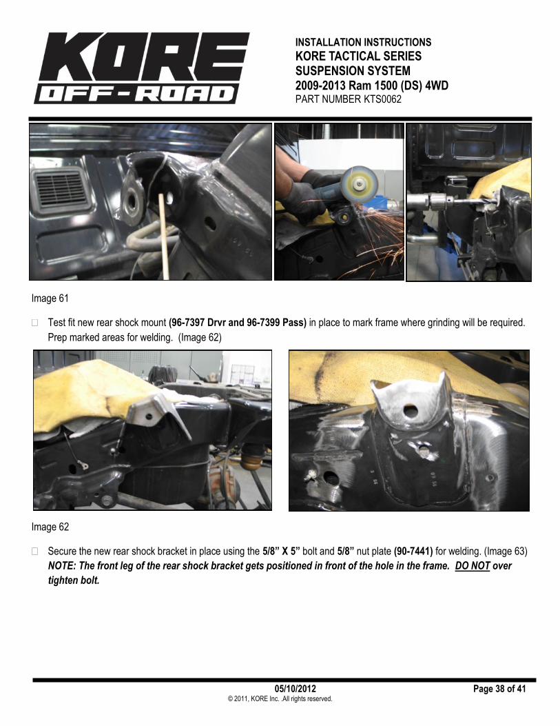
Test fit new rear shock mount (96-7397 Drvr and 96-7399 Pass) in place to mark frame where grinding will be required.
Prep marked areas for welding. (Image 62)
Image 62
Secure the new rear shock bracket in place using the 5/8” X 5” bolt and 5/8” nut plate (90-7441) for welding. (Image 63)
NOTE: The front leg of the rear shock bracket gets positioned in front of the hole in the frame. DO NOT over
tighten bolt.

INSTALLATION INSTRUCTIONS
KORE TACTICAL SERIES SUSPENSION SYSTEM 2009-2013 Ram 1500 (DS) 4WD PART NUMBER KTS0062
05/10/2012 Page 39 of 41 © 2011, KORE Inc. .All rights reserved.
Image 63
On both sides, tack weld the rear shock mounts (96-7397 Drvr and 96-7399 Pass) to the frame using at least (8) good tack welds. Weld the perimeter of the new shock mount bracket by alternating welding areas to avoid warping the metal. (Image 64)
Image 64
Once the welds have cooled, sand, prime and paint the welded areas with a quality paint. (Image 65)
Mount leg goes in front of hole

INSTALLATION INSTRUCTIONS
KORE TACTICAL SERIES SUSPENSION SYSTEM 2009-2013 Ram 1500 (DS) 4WD PART NUMBER KTS0062
05/10/2012 Page 40 of 41 © 2011, KORE Inc. .All rights reserved.
Image 65 REAR SUSPENSION REASSEMBLY
Install new rear coil springs (52162-1) into the upper coil spring mounting bucket and lower axle mount. (Image 66)
Image 66
Install new FOX rear shocks (FX6516) and mono ball spacers (213-18-018-A) in the upper mount using the 5/8” X 5” bolt, nut plate (90-7441) and washer. Torque the upper shock bolt to 135 ft./lbs. (Image 67)

INSTALLATION INSTRUCTIONS
KORE TACTICAL SERIES SUSPENSION SYSTEM 2009-2013 Ram 1500 (DS) 4WD PART NUMBER KTS0062
05/10/2012 Page 41 of 41 © 2011, KORE Inc. .All rights reserved.
Image 67
Install the previously removed OE bolt and mono ball spacers (213-01-131-A) in the lower mount.
Install rear upper sway bar mount drop bracket (96-7375 Drvr and 96-7376 Pass) using the 7/16” X 1 1/4” bolt, hard-ware and 8mm OE bolt. (Image 68)
Image 68
Install the sway bar end link to the extension bracket using the previously removed OE bolt and hardware. (Image 68)
Attach the brake line to the relocation bracket using the supplied 5/16” X 1” bolt and hardware. (Image 69) Note: Care-fully bend the OE brake line bracket to avoid contact with any surfaces. The factory zip tie may also need to be cut to provide enough slack for the lines new position.

INSTALLATION INSTRUCTIONS
KORE TACTICAL SERIES SUSPENSION SYSTEM 2009-2013 Ram 1500 (DS) 4WD PART NUMBER KTS0062
05/10/2012 Page 42 of 41 © 2011, KORE Inc. .All rights reserved.
Image 69
Zip tie the ABS lines to the brake lines.
Repeat procedure on the remaining side of the vehicle.
Carefully, center and reinstall the bed to the frame and secure using the previously removed OE hardware. Reattach all the previously disconnected wiring harnesses. NOTE: Be sure to align all the gaps between the cab and the bed evenly.
Re-secure the fuel filler neck to the rear fender using the previously removed OE hardware.
Reattach the tail light wiring harnesses and reinstall the taillights using the previously removed hardware.
Torque all the OE bolts according to factory specifications.
Reinstall wheels to the vehicle. Using a criss-cross pattern, tighten lug nuts to 130 ft. lbs.
Jack up the truck, remove the jack stands and lower the vehicle to the ground.
Reinstall the negative cable to the battery.
Check all components for proper operation and clearances. Pay special attention to the clearance between the tires/wheels and shocks, brake hoses, wiring etc.
Have the truck professionally aligned immediately.
Adjust headlights.

INSTALLATION INSTRUCTIONS
KORE TACTICAL SERIES SUSPENSION SYSTEM 2009-2013 Ram 1500 (DS) 4WD PART NUMBER KTS0062
05/10/2012 Page 43 of 41 © 2011, KORE Inc. .All rights reserved.
Important Maintenance Information It is the ultimate buyer’s responsibility to have all bolts / nuts checked for tightness after the first 100 miles and then every 1000 miles. The steering, suspension and driveline systems, plus wheel alignment should be inspected by a qualified professional mechanic at least every 3000 miles.
KORE INC. USA LIMITED WARRANTY KORE INC. warrants the listed products for the listed time period. This warranty does not apply to products which have been improperly applied or in-stalled. The consumer will be responsible for removing from the vehicle and returning any items, shipping prepaid, and for the reinstallation of the part upon return. A copy of the sales receipt is required. KORE INC. will repair or replace at its option, defective products or components. Exclusions from this warranty are the finish, any condition(s) caused by abnormal use or service, and product-specific limitations, if any, listed below. The loss of use of the product, loss of time, inconvenience, commercial loss or consequential damages are not covered. KORE INC. reserves the right to change the design of any product without assuming any obligation to modify any product already manufactured. This warranty gives you specific legal rights and you may also have other rights which may vary from state to state. There are no warranties, expressed or implied including any implied war-ranties of merchantability and fitness, which extend beyond this warranty period. There are no warranties that extend beyond the face hereof. Seller dis-claims implied warranty of merchantability. This warranty shall not apply to any product sold by KORE INC. which has been modified, customized or im-properly installed. No warranty applies to any part that is designed to be sacrificial and periodically replaced. Examples of these parts are spherical bearings found in shock absorbers, rubber bushings found in control arms, and rod ends found in end links. KORE parts are the finest quality possible. But these are high-performance, race-derived parts and therefore have limited life spans that are, like brake pads and clutch surfaces, dependent upon use and environmen-tal conditions. LIMITED ONE YEAR WARRANTY ON PARTS MANUFACTURED BY KORE INC. KORE INC. warrants any part it manufactures against defects in material and workmanship (except for finish or other cosmetic problems) for one year from the date of purchase. LIMITED WARRANTY ON SHOCK ABSORBERS SOLD BY KORE INC. Fox Racing Shox warrants absorbers against factory defects in material and workmanship (except finish) for 12 months regardless of mileage. “Finish” applies to shock shafts damaged by exposure to corrosive chemicals or abrasives. This warranty applies to the original purchaser and is non-transferable. For all Fox shock warranties, call 619-768-1800. RIGHTS RESERVED KORE INC. reserves the right to make changes in design, material and specification or to make product changes as deemed necessary without prior notice. Obligations or liabilities will not be assumed with respect to similar products previously advertised.
KORE TECH LINE (760) 855-1219