Embed Size (px)
Citation preview

KNOWLEDGE PARTNERSHIP PROGRAMME
South-South Technology Transfer
Low Carbon Building Technologies
Operational Manual
Technology and Action For Rural Advancement, New Delhi
Submitted to
Department for International Development (DFID)
IPE Global (P) Ltd.
November 2014
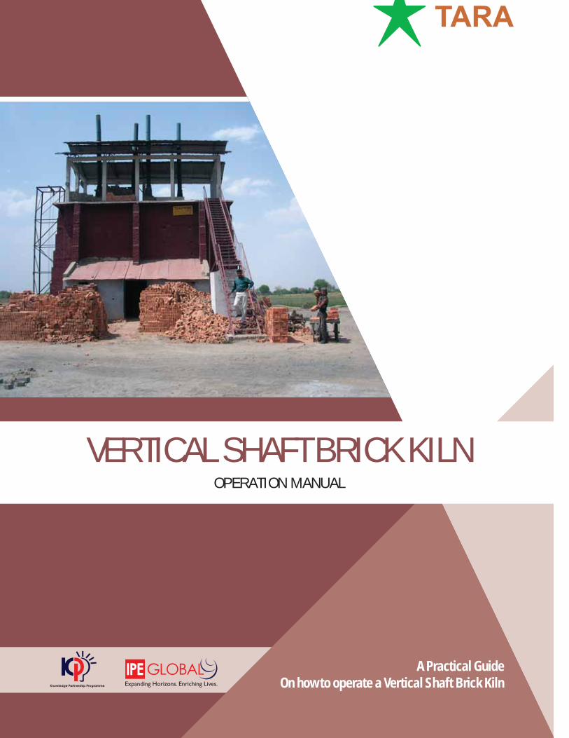
VERTICAL SHAFT BRICK KILNOPERATION MANUAL
A Practical GuideOn how to operate a Vertical Shaft Brick Kiln

Contact Details:Technology and Action for Rural Advancement B-32, TARA Crescent,Qutub Institutional Area,New Delhi-110016Phone Number: 011-26544100Email: [email protected], [email protected]
All the content or information present here is the exclusive property of Technology and Action for Rural Advancement (TARA). The content/ information contained here is correct at the time of publishing. The views expressed in this catalogue do not necessarily reflect the views of any organisation(s) associated with Technology and Action for Rural Advancement. No material from here may be copied, modified, reproduced, republished, uploaded, transmitted, posted or distributed in any form without prior written permission from TARA. Unauthorised use of the content/information appearing here may violate copyright, trademark & other applicable laws & could result is criminal or civil penalties.
©Technology and Action for Rural Advancement 2014

This operation manual is a practical method of describing the commissioning and operations of a Vertical Shaft Brick Kiln (VSBK). It is a result arisen out of the needs to respond to a worldwide interest for the energy-efficient and environment friendly brick firing technology, i.e. the VSBK technology. Generally, it is understood that the operation of a VSBK is a practical art, being mastered by the competent firemen through years of intense training. This is usually the case with the old technologies like the old clamp, Bull’s Trench Kiln or even the modern Hoffmann. The firing and the operation is usually done by firemen with traditional knowledge passed on through generations. Never have we been able to find out a practical manual on how to operate traditional kilns. Therefore, this manual is an attempt to overcome these barriers. In recent times, with the proliferation of the need of VSBK in various countries, there has been a need to write down a standard method or recipe that can be relied upon for operating a VSBK. These operational aspects are also country specific, since they depend on technical, social and geographical conditions particular to that country. Thus, the need to develop an operation manual, specific to conditions in Malawi was necessary.
This Malawi specific operation manual is based on more than a decade long practical working experience in Asia. It is expected to serve as a basic tool for workers, supervisors, managers and even entrepreneurs to delineate and control the art of stabilised operation of a VSBK and also commissioning the same.
This operation manual does not claim to be complete or perfect. It is in the hands of the users to make the best out of it and use it as a reference for further improvement. The authors would appreciate if you could share your ideas and work experiences to further improve this manual.
Preface

Acknowledgement
During the course of developing this manual, every effort was made to
include the existing knowledge base, along with interactions between
personnel associated with the VSBK technology.
We would like to acknowledge the support of various organizations,
The Swiss Agency for Development and Cooperation, India; TARA
Machines and Tech. Services Pvt. Ltd., India; Centre for Community
Organization and Development (CCODE), Lilongwe, Malawi; Eco bricks
Limited, Lilongwe, Malawi, TARA Machines and Tech. Services Pvt. Ltd.
and IPE Global, New Delhi; who have whole heartedly contributed
towards developing the same.
Our sincere thanks to various individuals, whose views have been accessed personally, through one-
to-one interactions, the internet and printed documents. Special thank to Heini Muller, Skat Nepal for
developing the first manuals. His inspirations and guidance were invaluable in designing many more.
The research efforts captured in this manual would not have been possible without the institutional support
given to the project organisations by Deutsche Gesellschalt fur Internationale Zusammenarbeit(GIZ) GmbH
and the Knowledge Partnership Programme (KPP) of the Department of International Development
(DFID), India. Managed and supported by IPE Global, the KPP aims to step up collaboration around ideas,
knowledge, evidence, accountability, technology and innovation, impacting the delivery of global public
goods and services and leverage Indian experiences to reduce poverty in LDCs.
Society for Technology & Action for Rural Advancement, India
OPERATION MANUAL 5
Chapter 1 Different Types of Brick Firing Technologies ...............................5
Chapter 2 Introduction to VSBK ......................................................................7
Chapter 3 Terminology Used in VSBK ...........................................................10
Chapter 4 Why VSBK? .....................................................................................14
Chapter 5 Green Bricks for VSBK ..................................................................15
Chapter 6 Use of Internal Fuel in VSBK operation ......................................18
Chapter 7 Materials and Equipments for VSBK Operation ........................23
Chapter 8 Materials and Manpower for Initial Firing ..................................24
Chapter 9 Fire Preparation and Initial Firing ...............................................25
Chapter 10 Fire Stabilisation and Fire Control ............................................33
Chapter 11 Checking Quality of Fired Bricks ...............................................35
Chapter 12 Potential Hazards In a VSBK ......................................................37
Chapter 13 Repair and Maintenance in a VSBK ...........................................38
Chapter 14 Duties of a Firemaster ................................................................40
Chapter 15 Some VSBK Common Issues During Operation ......................43
Figure 1: Schematic Diagram of a VSBK .........................................................1
Figure 2: 3D View of VSBK Technology ...........................................................2
Figure 3: Front Cross-Sectional Elevation of VSBK Shaft ..............................3
Contents
Figures
6 OPERATION MANUAL
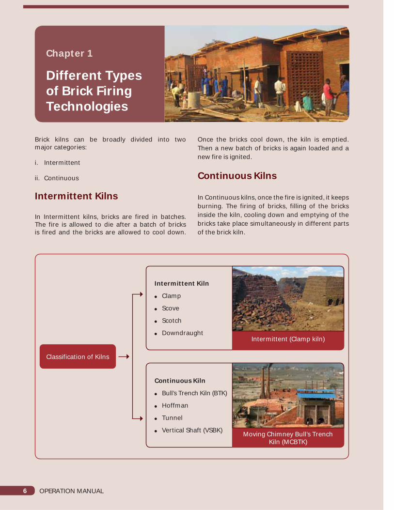
Brick kilns can be broadly divided into twomajor categories:
i. Intermittent
ii. Continuous
Intermittent Kilns
In Intermittent kilns, bricks are fired in batches. The fire is allowed to die after a batch of bricks is fired and the bricks are allowed to cool down.
Chapter 1
Different Types of Brick Firing Technologies
Once the bricks cool down, the kiln is emptied. Then a new batch of bricks is again loaded and a new fire is ignited.
Continuous Kilns
In Continuous kilns, once the fire is ignited, it keeps burning. The firing of bricks, filling of the bricks inside the kiln, cooling down and emptying of the bricks take place simultaneously in different parts of the brick kiln.
Classification of Kilns
Intermittent Kiln
Clamp
Scove
Scotch
Downdraught
Continuous Kiln
Bull’s Trench Kiln (BTK)
Hoffman
Tunnel
Vertical Shaft (VSBK)
Intermittent (Clamp kiln)
Moving Chimney Bull’s Trench Kiln (MCBTK)

OPERATION MANUAL 7
Chapter 2
Introductionto VSBK
The VSBK is a vertical kiln with a stationary fire and a moving brick arrangement. Figure 1 below shows the VSBK principle in a schematic diagram. The kiln operates like a counter current heat exchanger, with the heat transfer taking place between the air moving upwards and the bricks moving downwards.
CorrugatedTin Roof
Chimney
Lid / Cover
Green Bricks
Insulation
Fill
Fired Bricks
Pre Heating Zone
Central Firing Zone
Cooling Zone
Air Flows Upwards
Bricks MoveDownwards
Loading
Loading Platform
Loading Ramp
Space for Support Bars
Soil &RubbleInfill
Support BarsBrick Trolley
Unloading ofBricks
CentralFiringZone
SpyHoles
Figure 1: Schematic Diagram of a VSBK

8 OPERATION MANUAL
In a VSBK the shaft is loaded from the top in batches of green bricks. Each batch typically contains four layers of bricks, set in two distinct pre-determined patterns, called a normal batch or a zig-zag batch. The fired bricks are unloaded from the bottom of the shaft. The shaft itself can be divided into three distinct sections. The top section is the brick preheating zone, where the bricks are preheated with the exhaust heat from the firing zone, the middle section is the firing and heat soaking zone, where actual firing takes place and the lower section is the brick cooling zone, where the fired bricks cool down.
Fuel is usually added in two forms; internal fuel and external fuel. The internal fuel is added with the soil prior to brick moulding. Different internal
fuels used in VSBK are coal powder, fly ash, biomass fuels, such as rice husk and bagasse. Only coal is used as external fuel in VSBK. The external fuel is added along with the green brick batches from the top of the shaft. VSBK is a natural draft kiln, requiring no electricity for the supply of combustion air, which enters from the bottom of the kiln. It extracts the heat from the cooling bricks before reaching the firing zone.
The flue gases leaving the firing zone exchange heat with loaded dry bricks, thereby pre-heating them. The flue gases finally enter the chimney through the flue duct at a temperature of 60°C to 130°C. The stack of bricks rest on I or square shaped support bars (which can be removed or inserted) and supported in turn by a pair of horizontal beams across the arches in the unloading tunnel. For evacuation of the exhaust gases, typically, two chimneys are provided at the diagonally opposite corners of each shaft. The lids are provided to cover the shaft top, which directs the gases to the chimney through the flue duct. A single screw jack system is used for unloading the fired bricks.
What Happens Inside VSBK?Water Smoking
Once the bricks are set into the kiln and the firing starts, the first stage in the process, called water smoking, begins. This is when the remaining water between clay particles is drained off. This water always remains in the bricks that have been dried atmospherically and can never be drained off by the normal drying processes. The amount of water content at this stage varies between 2% (dry climate) to even 6% (tropical climate) depending on the climatic conditions, especially the relative humidity of that region. The water smoking process takes place between the outside air temperature and the boiling point of water (100°C). It is usually considered to be completed by 120°C. This first period of the kiln firing must be done very slowly. A very rapid rise in the temperature will cause the steam pressure to build up within the bricks, causing them to crack and shatter. The water smoking period is over when there are no visible instances of dense white smoke from the outlets.
Decomposition
The next stage in the firing process is decomposition. Many types of clay contain organic matter, which breaks down at approximately
Water Smoking

OPERATION MANUAL 9
200°C. It is not a burning process, as the burning of the carbon happens later. This part of the brick firing can proceed quickly. There is a slight expansion of the bricks in the kiln at this stage, but this is too small to be noticed, being less than one percent in the linear dimensions.
Ceramic Change
In the next stage, the temperature rises and the interstitial water, which is part of the crystal structure of the clay, is driven off. The result is the start of the irreversible change from clay to ceramic, from green bricks to fired bricks. This action begins very gently between 350°C and 450°C and increases to a maximum at 600°C, after which the action quickly fades away before 700°C. There is a little danger from the escaping steam and the firing can be continued quickly. Water vapour may be seen escaping from the kiln vents, which have dried during the decomposition stage. Theoretically, now completely dry clay particles in the bricks touch one another. However, the bricks hold together and do not collapse into a pile of dust, because the particles are fastened to each other by a process called sintering. This is not fusion in the vitrification sense, but a welding together of similar particles at points of extremely small contact.
Burning Out
Carbon and sulphur are present in the clay and are burnt by the process called oxidation. This process requires atleast the dull red heat of 700°C and reaches its climax around 800°C. Most of the carbon gets burnt by 900°C. It is essential that this process is thoroughly completed. With a large mass of bricks this may take a number of hours.
If the kiln is not allowed to remain at the required maximum temperature “soaking” long enough, bricks with a black core are produced, which are not as strong as the fully fired bricks. This is because of the stresses set up inside the brick that can cause failure. Clearly, different types of clay require different firing cycles, because the amount of carbon and sulphur varies from clay to clay. The courser clay, like fireclay and shales that are used to make bricks, often contain a higher percentage of carbon, which takes a lot of time to burn out despite the more open textures of these types of clay. During the burning out period, there will be little or no change in brick size. Any slight expansion is countered by the sintering and incipient vitrification.
Vitrification
This process within the fired brick begins at 800°C when the soda and potash in the brick start to flux the free silica. The vitrification progresses throughout the firing, filling the pores between the alumino silicate (original clay) particles and eventually incorporating these as well. Vitrification strengthens the bricks by welding the clay particles along with quartz particles through the formation of inter spatial glass. Above 1000°C, the fused alumino silicate starts to form mullite. These mullite crystals are long, sturdy needles, which considerably strengthen the final brick by binding the clay particles together.
The optimum firing temperature and the amount of soaking time allowed at that temperature, determines the balance required between the properties of strength and porosity in a fired brick. The higher the temperature, the stronger, but more brittle, the brick becomes and the porosity is reduced. The lower the firing temperature, the weaker and more porous are the bricks.
The fired bricks’ colour is also important when they are sold. This is affected by the iron content within the clay mass and the maximum firing temperature. The final colour also depends on the unloading temperature after firing. The soaking time does not affect the colour of the fired bricks.
Cooling
In the process of cooling, the bricks contract at a regular rate, except for the sudden contractions at the quartz and cristobalite inversions. Their compositions have little effect on the bricks during cooling, as they have already achieved their fired strength. It is only if cracks already exist in the bricks that these contractions can cause further failure. The glassy parts of the fired bricks sets solid with crystals if the temperature is high enough, binding the whole mass into a strong unit.
Bricks are made from coarse type of clay, which contains particles of fine and coarse sand, providing a more open structure. This helps the bricks to dry more easily by allowing the water to evaporate and also increases the brick’s resistance to thermal shock during the water smoking period of firing. The large mass of bricks being fired at any given time means that the optimum temperature has to be maintained for a substantive time to ensure that the heat thoroughly permeates the centre of all the bricks.

10 OPERATION MANUAL
Chapter 3
Terminology Used in VSBK
Terminology Description
Chimneys Chimneys are two vertical ducts connected diagonally at the shaft top.A Chimney helps in the passage of exhaust flue gas from the shaft.
Cooling zone The Cooling zone is in the lower part of the shaft. Since this part is used to cool the fired bricks, it is named as the cooling zone.
Damper Adjustable valves connected in the chimney to control the draught and also the exit of flue gases from the chimney.
Firing zoneThe firing zone is in the central part of the shaft. The temperature of this portion of the shaft is very high and firing of the bricks is undertaken isthis zone.
Flue ductsSpecially designed openings provided at the top of the shaft, which provide passage for flu gases from shaft towards the chimney. Each shaft has two levels of flue ducts.
I-beam The I-beams are fixed on the two sides of the lower portion of the shaft. The I-bars are placed above the I-beams.
Lid cover A lid cover is provided at the shaft top to cover the shaft, which prevents smoke and heat loss from the shaft top.
Loading platform Loading platform is at the upper part of the VSBK, where green bricks are stored before stacking into the Shaft.
Peep-hole pipeThe peep-hole pipe is fixed in the outer wall of the VSBK shaft. It is used for monitoring the condition of the fire inside the shaft. It is also for monitoring the temperatures of the different batches.

OPERATION MANUAL 11
Pre-heating zone A pre-heating zone is an area where the green bricks are dried and pre heated before firing. It is in the upper part of the shaft.
RampRamp is a structure provided to join two different vertical levels, group floor and loading platform. With the help of a ramp the green brick are transported to a loading platform the ground.
Shaft Shaft is rectangular shape structure, where the bricks are fired. It is made of fire resisting bricks called fire-bricks or refractory bricks.
Hydraulic Unloading Device
It is a device connected below the ground, vertically below the shaft for unloading the fired bricks. It consists of a steel shaft and a hydraulic power pack. For each shaft,a hydraulic unloading system is provided.
Square barIt is a square iron bar. The square bars are placed at the bottom of the shaft, on top of the I-beams. It bears the total load of the bricks in the shaft.
Trolley guide The trolley guide is fixed on the lower wall of the shaft. It is used to guide the vertical movement of the trolley, while unloading the fired bricks.
Trolley track A trolley track is fixed in the unloading tunnel ground. It helps the unloading trolley to move in and out of the tunnel.
Unloading trolley
It is a rectangular shaped trolley made out of iron, used for carrying a batch of fired bricks. It is connected with the wheels undemeath. Fired bricks are unloaded on the unloading trolley and brought outside from the unloading tunnel. For each shaft, two pairs of unloading trolleys are provided.

12 OPERATION MANUAL
Chimney
Ramp
Shaft
Preheating Zone
Firing Zone
Cooling Zone
Damper
Loading Platform
Figure 2: 3D View of VSBK Technology

OPERATION MANUAL 13
Peephole pipes
Trolley I Beam
Screw Jack
Cooling Zone
Firing Zone
Preheating Zone
Flue ducts
Figure 3: Front Cross-Sectional Elevation of VSBK Shaft

14 OPERATION MANUAL
Chapter 4
Why VSBK?
Environment Friendly
Brick kilns are one of the major sources of air pollution. The VSBK technology can reduce pollution by 70% when compared to available technologies in Malawi. The VSBK uses only coal for firing, so the deforestation problem can also be controlled.
Economically Viable
Despite high investment, VSBK is a profitable business. The savings made during the operation makes it economically viable. Quality of bricks produced also earns higher profits
Better Working Condition
The VSBK technology provides cleaner working environment, with lesser dust and smoke, thus minimising health hazards.
Year Round Production
Weather factors have minor influence in VSBK operations. With a roof protection, the kiln can be operated a year round.
Less Land Requirement
VSBK requires less space when compared to other brick making technologies. This makes VSBK a much better option for entire Malawi
Flexibility in Production
In VSBK, the bricks can be produced according to the demand. If the demand is high, all the shafts can be operated, if not, only a limited number can be operated to meet the demand.
Low Maintenance Cost
The kiln requires very little maintenance once it is constructed, thus emerging as a very economically viable option.
VSBK has Following Advantages:
Energy Efficient
VSBK is energy efficient when compared to a Fixed Chimney Bull’s Trench Kiln (FC-BTK). It saves about 25% to 40% of coal. Investment in coal is the major production cost involved in any kiln operation.
World’s Most Energy Efficient Brick Kiln: VSBK

OPERATION MANUAL 15
Chapter 5
Green Bricksfor VSBK
Importance of Green Bricks in VSBK
In VSBK, bricks are fired inside the shaft with fixed dimensions and within a short time period of just 24 to 28 hours. Because of these characteristics, the VSBK is a demanding technology, which provides less tolerance for any error. Hence, the quality of the fired bricks in VSBK depends very much on the quality of green bricks we feed into the shaft.
The quality of the green bricks is defined by its soil quality, soil processing techniques, green brick making process, its shape, size and dryness. The right soil quality is one of the most important factors in the VSBK technology to determine the fired brick’s quality. In general, VSBK requires clayey soil with relatively higher plasticity. These kinds of soil suit the rapid firing process like in VSBK. Since bricks are fired in rectangular shafts with fixed dimensions, the green bricks must have proper shape and size to fit into the shaft. The shaft size is designed according to size of dry green bricks. Hence, the green bricks’ dimensions cannot be altered after the shaft is constructed. Because of its short firing cycle, green bricks must be completely dried, if not, it might result into the splitting of bricks upon firing. The soil must be properly aged and mixed before making bricks. It must not have any kind of textures or cracks, if not, it may result into higher breakage and bad ring in the fired bricks.
Green Brick Making Procedure
Green brick making is an art. It is, in itself, a very vast and complex subject. Hence, it is not possible to cover the whole green brick making in this chapter. Green brick can be made either manually or by a machine.
Green bricks
Manual green brick making must include the following steps:
Soil selection
Soil mining
Soil storing and ageing
Pugging
Moulding
Drying and stacking

16 OPERATION MANUAL
S. No. Test parameters on dry basis (% by mass) Percentage (%)
Chemical Properties
1 Loss of ignition 2-3
2 Silica as SiO2 55-65
3 Iron as Fe2O3 >3
4 Alumina as Al2O3 15-25
5 Sodium as Na2O <1
6 Potassium as K2O <1
7 Calcium as CaO <1
8 Magnesium as MgO <1
9 Organic Carbon as C >1
Physical Properties
1 Sand 20 - 45
2 Silt 25 - 45
3 Clay 20 - 35
4 Liquid limit 25 - 38
5 Plasticity index 7 - 16
6 Volumetric shrinkage 15 - 25
In mechanised green brick making, pugging and moulding is done by a machine, either by an extruder or by a soft moulding machine.
Soil Selection
Making good quality green bricks starts with the selection of right kind of soil. In general, good quality bricks cannot be achieved from all types of soil. In case of VSBK, it is especially true due
to dynamic load. Thus, VSBK demands soil with better qualities when compared to FC-BTKs. VSBK requires soil with specific chemical and physical properties. Therefore, scientific testing of the soil is required before using it for making green bricks for VSBK.
The recommended chemical and physical properties of soil for VSBK are given below:
Disclaimer: These are suggested parameters for appropriate soils. Soils beyond these characteristics needs to bemodified accordingly.

OPERATION MANUAL 17
Soil Mining
Soil mining is the process of excavating the selected soil for making bricks and transporting it to the ageing yard, if required. Mining can be done horizontally or vertically. In horizontal mining, the same layer of soil is excavated, where as in vertical mining, two or more layers of soil are excavated.
Soil Storing and Ageing
Soil storing and ageing is the process of piling up the soil in moist conditions for certain duration of time. Soil ageing is an important aspect of green brick making, which is often neglected. Soil ageing is important because it softens and breaks bigger soil lump into smaller pieces and at the same time it ensures adequate cohesion and mobility, which is the actual source of plasticity and ductility.
Pugging
Pugging is the process of breaking soil lumps into smaller grain size and uniformly mixing it with water. Pugging ensures homogeneity of soil for brick making. Pugging can be done either manually or by machine.
Moulding
Moulding is the process where pugged soil is given a specified shape of the bricks, using mould boxes. Moulding can be done through the soft mud moulding machine.
Drying
Drying is the process of removing the water content in green bricks mechanically. Drying can be done naturally under the sunlight or by using forced dryer. Drying assumes more importance in VSBK because of its short cycle firing system. The drier the green bricks the lesser energy the energy required and lesser the damage during the heating up phase.
Soil storing and ageing
Use of pug mill for soil processing
Green brick moulding
Mechanized mining of soil

18 OPERATION MANUAL
Chapter 6
Use of Internal Fuel in VSBK Operation
The quality of bricks is good and there is a high yield of saleable bricks.
The environmental impact of using waste is either negligible or beneficial.
The following needs to be engineered for obtaining the optimum property of fired bricks, when using internal fuel.
1. Particle Size of the Internal Fuel
Should not be more than 2mm. If required, the internal fuel should be grinded in a disintegrator/pulveriser and sieved in a 2mm mesh. The finer particles should be used as internal fuel and the larger particles should be either re-grinded or used as an external fuel during VSBK firing.
2. Calorific Value of the Internal Fuel
Calorific value should always be greater than 1000 KCal/kg to minimise the quantity to be added.
3. Amount to be Used
The amount depends on the calorific value of the internal fuel, the amount of energy to be added with the soil and most important, the properties of the soil, i.e. its plasticity. The latter is the most important factor, since the quality of the fired bricks depends on the amount of materials added.
4. Mixing Process
For any kind of internal fuel used in the soil, a manual mixing process is not recommended. Uniform mixing is the key to achieving consistent property. Experiences from India, Nepal show that uniform mixing cannot be achieved through manual mixing. Thus, any form of mechanised mixing is preferred to achieve the uniform properties.
What is Internal Fuel?
The use of internal fuel in brick making is based on the premise that substituting the wastes into the brick making process, either as fuel, pore opening or anti shrinkage materials, can improve the profitability of brick making enterprises, reduce the working hazards and also reduce the environmental impact of brick making.
Different types of domestic, agricultural and industrial wastes have an acceptable heat value and therefore have a potential for use in domestic or industrial processes that require heat. Some wastes, like boiler ash, slags, charcoal wastes, rice husks, tobacco wastes etc. can facilitate clean burning thus less pollution when compared to conventional fuels such as coal or wood. Certain industrial wastes act as fluxes, thereby lowering the firing temperature and hence the energy required to form the ceramic bonds in clay mixes. This will obviously reduce fuel use and its associated costs proportionally.
Criteria for Internal Fuel Use
The following criteria should be met before using waste materials in brick making to reduce external energy consumption:
The cost of waste, including transportation to the site is economically viable.
The capital cost of the equipment required is low.
The technology is simple, reliable, and safe and does not require a large investment in workforce.
The supply of the waste material is guaranteed over a sufficiently long period of time.

OPERATION MANUAL 19
Technical Aspects of Internal Fuel Use
The energy required for brick making varies widely and depends on many factors i.e.
Type of clay used, its plasticity, grain size, vitrification temperature and the phases present
Type of fuel used; its calorific value, grain size and volatility
Mixing process of internal fuelwith soil
Drying and firing process
Some clay contains organic matter that acts as a fuel when bricks made from the same materials is fired, reducing the external energy requirement. However the presence of too much organic matter results in a friable and inferior brick. Depending on the characteristics of clay, in Malawi, the temperature required for vitrification is around 850 to 950°C. Such a temperature is generally reached by the use of medium grade coal. If wastes and residues are to be partially replaced, then they should have a similar calorific value and exhibit comparable combustion properties. If the additive is of lower quality, then it requires to be added in greater quantity. However, greater quantity of additives will also reduce the properties. Thus, the required quantity to be added needs to be tested and tried on a small scale.
Another important aspect is the mixing process of the internal fuel with soil. To achieve a consistent quality in the fired product, the internal fuel needs to be mixed in a uniform manner. Too fine materials (<1mm) is difficult to mix and achieve consistency. Materials that are too coarse, will result in greater voids thereby reducing the fired bricks’ properties. The suggested grain size should be around 2mm. For achieving uniform mixing, use of a mechanised process is a primary requisite. A manual mixing process cannot achieve the desired results. Use of Pugmill is absolute necessary.
Poor quality green bricks as a result of improper mixing
Uniform mixing characteristic of soil and additives

20 OPERATION MANUAL
Types of Internal FuelThere are various types of internal fuels that can be used in brick making. Some ideas are given here.
Fuel/Waste Calorific Value (KCal/kg)
Rice husk 2800 – 3800
Rice husk ash (white) 500
Rice husk ash (black) 1500 – 2000
Bagasse 4500
Charcoal 5000 – 7000
Sewage sludge 2300 – 5400
Sawdust 3800 – 4300
Coal mining waste 800 – 1000
Tobacco dust 1000 – 2000
Paper industry sludge 1600 – 4500
Textile industry waste 1500 – 2500
Coal 3500 – 7000
Boiler ash 700 – 1500
Rice husk as an internal fuel Rice husk as an internal fuel

OPERATION MANUAL 21
Charred waste biomass (Ipomiea or lantana or any other available)
Waste slag coal as an internal fuel
Tobacco dust as an internal fuel
Coal dust as an Additive
Sponge iron waste as an internal fuel
Textile industry waste as internal fuel

22 OPERATION MANUAL
Advantages of Using Internal FuelGenerally, when organic materials, such as saw dust, rice husk, groundnut husk etc. are added to the bricks before firing, their mechanical strength is reduced. Adding too much of such materials as an internal fuel can make the green brick too porous and friable, brittle and tending to crumble during handling and transportation. It is this limitation, rather than lack of compressive strength that makes the bricks unsuited for the purpose. The amount of organic matter that can be embodied in clay bricks as a fuel substitute is thus limited. With wastes that act as fluxes, conversely, compressive strength may be increased. If such an increase is not required, the addition of a flux may mean that, as an alternative, bricks can be fired at a lower temperature, saving fuel, while maintaining acceptable properties.
The density of common bricks is typically in the range of 1.60 – 1.80 gm/cm3. When particulate fuel is included in the bricks, it burns away and leaves pores. Thus, the density of the final product is reduced. On the other hand, they are somewhat less strong and durable. If density falls below 1.60 gm/cm3, bricks would not be durable enough to be used for construction purposes.
When internal fuel or fluxes are added to the soil before moulding, the mouldability characteristics might change. In such cases, more water is usually added to the mix to regain mouldability. This is likely to mean poorer handling properties and increased drying shrinkage. Thus, the clay to be used in the pugmill and the moulding needs to be modified accordingly. In Malawi, black and morom soil can be found. The typical internal fuel that can be used in Malawi is tobacco ash and boiler ash.
Coal is referred to as peas and duff in Malawi. Malawi has one of the most suitable quality of coal required to be used in VSBK system. With a calorific value between 26 - 29 MJ/kg it is of appropriate quality. Adequate quantity is also available in the Northern part of Malawi with explorable deposits in the Southern past also. During the feasibility study a substantial quantity of industrial waste materials from coal, tobacco and other industries have been seen. Tests show a result of around 27
MJ/kg (Duff coal) - 9MJ/kg (Tobacco dust) making it most suitable to be used in green brick making without affecting the quality of the fired product.
Some types of internal fuel can cause the fired bricks to change their colour. This is mainly caused due to appreciable lime or iron content within the additive. In India, an addition of sponge iron waste is highly beneficial to produce a good red colour in the fired brick. This is mainly caused by the high iron content within the sponge iron waste. Alternatively, presence of iron also acts as a flux, which decreases the vitrification temperature, thereby decreasing energy consumption. For internal fuel bricks, reduction in chemical reaction occurs when insufficient air gets to the fuel. The result is inefficient burning of bricks and the fuel remains partly burnt. Also, during the firing, if the bricks are placed too close together in the kiln, black reduction spots can occur where the surfaces are in contact. Bricks with reduction cores and spots are more likely to exhibit sub-standard properties. Often consumers do not like the appearance and are reluctant to buy the bricks. Therefore firing of internal fuel bricks has to be for a long period in a slow manner with increased airflow. This problem does not occur when the firing is done in a fixed chimney Bull’s Trench Kiln. This is mainly due to its extremely slow firing schedule, with appreciable air flow through the gaps between the brick setting.
In some cases, there is an interesting advantage associated with internal fuel use in brick making. Fired clay bricks can incorporate harmful or even heavy metal compounds found in some internal fuels. Usually a fired brick can contain within its structure these harmful substances without significant leaching. Hence there is no risk to either builders or users of these bricks. Brick making therefore has potential of being the means of disposal of heavy metals and harmful substances, which can otherwise find its way into human consumption. Internal fuel use in brick making can also reduce the suspended particulate matter released into the atmosphere, when coal is burnt as an external fuel. The process is similar as described above.

OPERATION MANUAL 23
Chapter 7
Materials and Equipments for VSBK Operation
Figures given in the table below is applicable for a two shaft VSBK only.
Sl No Description Quantity
1 Unloading Trolley 4nos
2 Hydraulic mechanism (for unloading fired bricks) 2nos
3 Trolley track (to drive unloading trolley) 50meters
4 Wooden planks 36 nos
5 Nuts, Bolts & Washers As per requirement
6 Hand drill machine 1Set
7 M.S. Drill Bits As per requirement
8 Plain galvanised metal sheet (for covering the woods) 5 nos of 3 ft x 2ft or Approx 15 sq ft.
9 Nails 4 kg.
10 Iron rod 2 nos.
11 Square Bars 16 nos.
12 Tongs 8 nos
13 ‘J’ hook 8 nos
14 Weighing balance 2 set
15 Wall clock 1 set
16 P.V.C. safety helmet As per requirement
17 Gloves As per requirement
18 Knife 4 nos
19 Hammer for breaking coal 6 nos
20 Shovel for coal 4 nos
21 Bucket 4
22 Tools kit (Spanner set, sheet cutter, screw driver, hammer, chisel, etc.) As per requirement
23 Provision for necessary lighting As per requirement

24 OPERATION MANUAL
Chapter 8
Materials and Manpower for Initial Firing
Figures given in the table below is applicable for a two shaft VSBK only.
Sl. No. Description Quantity
1 Firewood (2-3 feet length and 1-3 inch diameter) 600 kg
2 Dried green bricks (for loading shaft) 10,000 nos
3 Red bricks (preliminary shaft loading) 500 nos
4 Lighting oil 20 lts
5 Broom 8 nos
6 Coal (Bituminous) (C.V. 4500 – 5000 kilo calories per kg) 20 tonnes
7 Nylon rope 20 meter
8 Lighting oil 4 nos
9 Fire Master (for 8 hourly shift duty) 6 persons
10 Fire person for other activities (for 8 hourly shift duty) 18 persons
12 Supervisor (for overall management) 3 persons

OPERATION MANUAL 25
Chapter 9
Fire Preparation and Initial Firing
The firing process in VSBK can be visualised in the sequential flowchart given below:
Firing Preparation
Shaft Drying
After construction, shafts are generally wet because of the water used during the construction period, or because of the rain at the time of construction. Drying can be done naturally. Keep the dampers, lid cover and unloading tunnel open to allow the air flow through the shaft for 10 to 14 days after the construction is complete. The air dries out the moisture present on the surface of the shaft structure.
Force drying may be required if the surface is too wet. For forced drying, prepare the firing pit at the bottom of the shaft by placing the square bars on top of the I beams. Then put a layer of bricks on top of the square bars. Add 15 kg of coal, crushed into a size of 3-4 inch, on top of the brick layer, along with 10 kg of wood, chopped into 2 ft to 3 ft in length. Close the lid cover and keep the dampers open. Ignite the fire by spraying some kerosene on coal and chopped wood. Keep the fire on by adding coal on the pit at the bottom of the shaft until there is no moisture condensation at the bottom of the lid cover.
Fire Preparation
Shaft Drying
Initial Loading
Initial Firing
Fire Ignition
Fire Stabilization
Normal Operation
Loading & Unloading
Drying up shaft for initial loading

26 OPERATION MANUAL
Initial Loading
The shaft is loaded from the bottom with green bricks and coal. The firebox is prepared at the bottom of the shaft to ignite the fire. Then the bricks are loaded in a pre-determined pattern, known as brick batch, up to the top of the shaft. Each batch consists of four layers of bricks. The first and the third layer of bricks in the batch are simply known as normal layers, where as the second and the fourth layer of bricks in the batch are known as the Chula layers, where the bricks are placed on its edge with a gap in between, providingspace to feed the coal and insert the square bars during unloading.
Detailed Procedure of Loading Shaft for Initial Firing
1. Keep the I-bar in a correct position.
2. Keep good quality fired bricks on thesquare bars.
3. Stack four layers of green bricks to make a firebox.
4. Stack other layers of green bricks and keep the wood pieces in between. This layer is known as the layer pattern.
5. Put a layer of green bricks with a hole (chula) in between, so as to make a room to insert the I-bars. Put coal and firewood in the layer. This layer is known as chula pattern.
6. Above this layer, make the layer pattern and put firewood and coal in between the bricks.
7. Again, above this layer, make the chula pattern of green bricks and fill the holes (Chula)with coal.
8. On the layers pattern above this, it is not necessary to keep firewood and coal.
9. Procedure seven and eight must be repeated till the shaft is fully loaded.
Coal Quality
The most important aspect in VSBK firing is using the right quality of coal. In this type of short cycle firing, generally a low volatile coal is used so that the heat is released in a gradual manner, appropriate to the firing schedule. If the heat release rate is very high, the fire tends to move rapidly, resulting in higher heating of the temperature rate per hour and hence quicker unloading. A faster unloading rate undermines the required heating temperatures, soaking time and cooling down temperatures, resulting in bricks with poor rings, cracks and bloating.
Layer Chula
A fired brick batch being unloaded
Loading bricks for the initial firing

OPERATION MANUAL 27
The VSBK works best with the following specified qualities of coal:
Coal quality specification Range
Proximate analysis, % by mass
Moisture 1% - 2%
Ash 25% - 40%
Volatile matter 15% - 20%
Fixed carbon 35% - 45%
Ultimate analysis, % by mass
Hydrigen as applicable
Nitrogen as applicable
Sulphur less than 1%
Oxygen as applicable
Gross calorific value, Kcal/Kg 4500 - 5500
Distribution of coal in Chula layer Fire box prepared for the initial firing

28 OPERATION MANUAL
Firing DetailsInitial Firing
For firing, green bricks and coal are loaded from the top of the shaft. Initially a higher amount of coal is used at the bottom most batches, gradually reducing in subsequent layers to the top. During the initial firing operation, a fire with wood is lit in the firebox at the bottom of the brick setting. Firewood is continuously stoked till the bricks in the firebox become red hot. At this time the firebox is sealed with mud for complete combustion. After around 8 to 10 hours the sealing is opened for natural draft to proceed. When the maximum temperature reaches above the central part of the shaft, the batch is unloaded.
Detailed Procedure of Initial Firing
All the shaft and dampers should be opened before initiating the firing process.
1. Firing Process
At first, a few pieces of firewood should be dipped into kerosene. These pieces should be lit after putting them inside firebox. Feed more firewood steadily inside the firebox so that firing continues for three to four hours. It is important not to put all the soaked firewood at once, as it would lead to constant fire inside the firebox even when the outside fire would be off. Check the fire inside the firebox from time to time. The bricks will gradually start getting red and the coal around the bricks will
start to combust. In this condition, there will be smoke coming out from the peep-holes, chimneys and the shaft.
2. Process of Closing the Firebox
Put bigger sized firewood inside the firebox. Close the firebox with fired bricks and a mud plaster from the outside once the fire is properly ignited and a black smoke starts coming out of the shaft and the chimney. This will control the air pressure and fire.
3. Loading and Unloading Process
After 8-10 hours of setting the fire, locate the area of the firing. The firing location can be located by measuring the temperature by a Thermo-couple. If the maximum temperature is above the central zone, then the firebox needs to be opened. The first batch of the bricks will be unloaded, as the maximum temperature crosses the central zone of the shaft. After an hour of opening the firebox, it is time for unloading. If the fired bricks of the lower level of the shaft are not very hot, it can be concluded that the firing zone is in the upper portion of the shaft. The loading and unloading of the bricks are done at the same time. Within 24 hours of setting the fire in the shaft, only three to four batches of the fired bricks will be unloaded. In the beginning, open loading would be appropriate, as this will help to move the fire upward.
Detailed Procedure of Loading
Stack green bricks in the standard pattern.
Bricks should be stacked uniformly across the shaft’s cross section. Always stack the bricks with the mark/logo facing inwards.
Lighting up for initial firing
Closing the firebox
OPERATION MANUAL 29
Leave 10 mm clearance between the stacked bricks and shaft walls to prevent any friction against the shaft walls.
For keeping or maintaining a uniform horizontal level, clay is used while loading bricks ofuneven shapes.
Green bricks should be stacked in a manner that the gap between the bricks is more in the periphery of the shaft and a smaller gap in the centre portion of the shaft.
Coal should be crushed to a uniform size (25-50 mm) and spread in between the bricks’ layers in a manner that more coal is spread in the periphery of the stacked layers and less in the centre. To maintain the uniform temperature across the shaft cross section, a little more coal is fed in all the four corners.
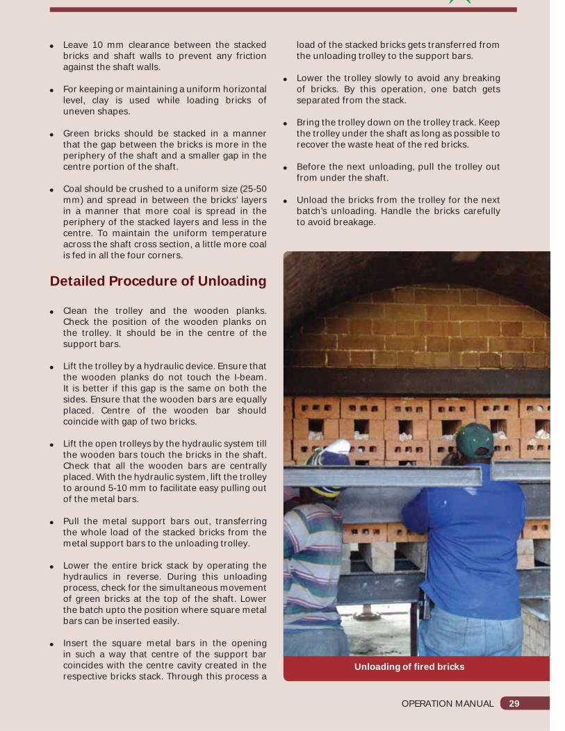
Detailed Procedure of Unloading
Clean the trolley and the wooden planks. Check the position of the wooden planks onthe trolley. It should be in the centre of the support bars.
Lift the trolley by a hydraulic device. Ensure that the wooden planks do not touch the I-beam. It is better if this gap is the same on both the sides. Ensure that the wooden bars are equally placed. Centre of the wooden bar should coincide with gap of two bricks.
Lift the open trolleys by the hydraulic system till the wooden bars touch the bricks in the shaft. Check that all the wooden bars are centrally placed. With the hydraulic system, lift the trolley to around 5-10 mm to facilitate easy pulling out of the metal bars.
Pull the metal support bars out, transferring the whole load of the stacked bricks from the metal support bars to the unloading trolley.
Lower the entire brick stack by operating the hydraulics in reverse. During this unloading process, check for the simultaneous movement of green bricks at the top of the shaft. Lower the batch upto the position where square metal bars can be inserted easily.
Insert the square metal bars in the opening in such a way that centre of the support bar coincides with the centre cavity created in the respective bricks stack. Through this process a
load of the stacked bricks gets transferred from the unloading trolley to the support bars.
Lower the trolley slowly to avoid any breaking of bricks. By this operation, one batch gets separated from the stack.
Bring the trolley down on the trolley track. Keep the trolley under the shaft as long as possible to recover the waste heat of the red bricks.
Before the next unloading, pull the trolley out from under the shaft.
Unload the bricks from the trolley for the next batch’s unloading. Handle the bricks carefully to avoid breakage.
Unloading of fired bricks
30 OPERATION MANUAL
Chapter 10
Fire Stabilisation and Fire Control
What is Fire Stabilisation?
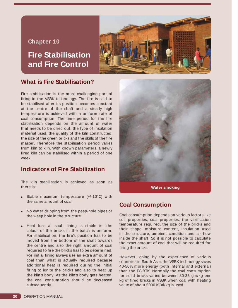
Fire stabilisation is the most challenging part of firing in the VSBK technology. The fire is said to be stabilised after its position becomes constant at the centre of the shaft and a steady high temperature is achieved with a uniform rate of coal consumption. The time period for the fire stabilisation depends on the amount of water that needs to be dried out, the type of insulation material used, the quality of the kiln constructed, the size of the green bricks and the skills of the fire master. Therefore the stabilisation period varies from kiln to kiln. With known parameters, a newly fired kiln can be stabilised within a period of one week.
Indicators of Fire Stabilization
The kiln stabilisation is achieved as soon asthere is:
Stable maximum temperature (+/-10°C) with the same amount of coal.
No water dripping from the peep-hole pipes or the weep hole in the structure.
Heat loss at shaft lining is stable ie. the colour of the bricks in the batch is uniform. For stabilisation, the fire’s position has to be moved from the bottom of the shaft towards the centre and also the right amount of coal required to fire the bricks has to be determined. For initial firing always use an extra amount of coal than what is actually required because additional heat is required during the initial firing to ignite the bricks and also to heat up the kiln’s body. As the kiln’s body gets heated, the coal consumption should be decreased subsequently.
Coal ConsumptionCoal consumption depends on various factors like soil properties, coal properties, the vitrification temperature required, the size of the bricks and their shape, moisture content, insulation used in the structure, ambient condition and air flow inside the shaft. So it is not possible to calculate the exact amount of coal that will be required for firing the bricks.
However, going by the experience of various countries in South Asia, the VSBK technology saves 40-50% more energy (both internal and external) than the FC-BTK. Normally the coal consumption for solid bricks varies between 30-35 gm/kg per kg of fired bricks in VSBK when coal with heating value of about 5000 KCal/kg is used.
Water smoking

OPERATION MANUAL 31
What Happens if too much of Coal is Added?
Excessive usage of coal can lead to a serious danger of the shaft getting heated too quickly, leading to structural damages within the shaft’s lining and the kiln’s body and even a serious meltdown of the bricks. Considering the potential long term damages resulting from adding too much coal in the beginning, it is recommended to start a first time shaft firing with a slightly reduced amount of coal, slowly adding energy as and when required.
Detailed Procedure to move up the Fire
1. If the unloading time is short, the fire may move downwards. Therefore, the fire master must load the shaft with loose batches, having half inch gaps in between the bricks. These gaps help the air to flow easily, helping the fire to move up.
2. To move the fire up, both dampers must be kept open completely. However, the lid covers must remain closed. If the fire does not move up, the lid covers may be opened.
Detailed Procedure to move the Fire Down
1. Batches must be unloaded in a short period.(It would be better, to avoid such an action)
2. Open the chimney damper in 22 degrees. (Damper must be open at number two.)
3. Use bigger pieces of coal as they would urn slowly.
4. Use tight loading.
The Impact of Size of Coal in FiringThe size of the coal is an important tool at hand to control the fire. It defines the:
Position of the fire
Length of the fire zone
Soaking time
A small sized coal (<1 cm) will ignite too soon and the position of the fire will tend to move up quickly, considerably decreasing the soaking time.
A big sized coal (>5 cm) will ignite very slowly and the fire zone will tend to move lower, increasing the soaking time. More over, the length of the fire zone will be longer.
By using mixed sized pieces of coal and inclusive dust particles, it becomes impossible to control the temperature and the position of the fire. The dust particles tend to ignite too fast, whereas the big coal lumps burn for a longer duration, resulting into a longer fire zone.
An ideal size of coal for VSBK is between 3 cm to 5 cm in diameter. However, the fire masters need to determine the appropriate size according to the types of coal available.
Use of lid cover
Moisture release during initial firing
32 OPERATION MANUAL
Chapter 11
Checking Quality of Fired Bricks
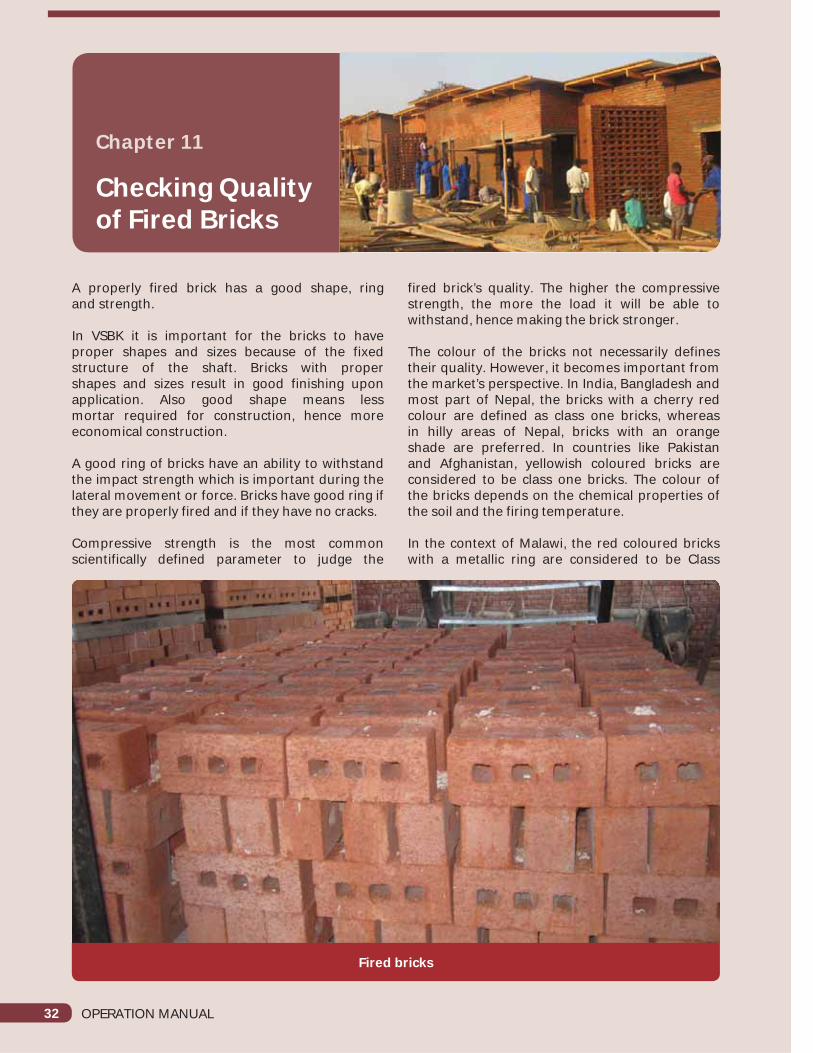
A properly fired brick has a good shape, ringand strength.
In VSBK it is important for the bricks to have proper shapes and sizes because of the fixed structure of the shaft. Bricks with propershapes and sizes result in good finishing upon application. Also good shape means lessmortar required for construction, hence more economical construction.
A good ring of bricks have an ability to withstand the impact strength which is important during the lateral movement or force. Bricks have good ring if they are properly fired and if they have no cracks.
Compressive strength is the most common scientifically defined parameter to judge the
fired brick’s quality. The higher the compressive strength, the more the load it will be able to withstand, hence making the brick stronger.
The colour of the bricks not necessarily defines their quality. However, it becomes important from the market’s perspective. In India, Bangladesh and most part of Nepal, the bricks with a cherry red colour are defined as class one bricks, whereas in hilly areas of Nepal, bricks with an orange shade are preferred. In countries like Pakistan and Afghanistan, yellowish coloured bricks are considered to be class one bricks. The colour of the bricks depends on the chemical properties of the soil and the firing temperature.
In the context of Malawi, the red coloured bricks with a metallic ring are considered to be Class
Fired bricks

OPERATION MANUAL 33
one bricks. The appropriate dimensions of the bricks are 230X110X75 mm as per the standards in Malawi.
The following parameters define the qualityof bricks:
1. Ring of fired bricks
a. Good (when the fired bricks stroked by small hammer produces a “metallic” sound they are known as metallic ringing bricks)
b. Average
c. Flat (When the bricks hammered by a small hammer give a dull and flat sound)
If fired bricks give a good ring then the bricks have been fired properly.
2. Colour of fired bricks
a. Cherry red
b. Orange
c. Pale orange
If the fired bricks give a cherry red colour then the quality of the fired product is considered good.
3. Regular shape and surface finish of the bricks
a. Good (no bending, blistering, regular shape and size, corner not broken)
b. Average
c. Bad
If fired bricks have good shape and finishing then the bricks have been properly made and handled and the fired product is considered good.
4. Strength of the bricks
a. Good
b. Average
c. Bad
If fired bricks give a good compressive strength then the quality of the fired product is considered good.
5. Cracks in the bricksa. Yesb. No
If fired bricks have no cracks it gives good ring, then the bricks have been fired in proper firing condition and considered good.6. Melting of bricks
a. Yes
b. No
If fired bricks have no melting, then the bricks have been fired properly and considered good.

34 OPERATION MANUAL
Chapter 12
Potential Hazards in a VSBK
Improper fencing on the platform level: the green bricks stacked might fall down, injuring any person working below.
Not wearing mask while loading
Not wearing helmet, mask and shoes while unloading
Falling of a square bar on foot while handling improperly
Picking up of hot fired bricks by bare hands
Passing green bricks for loading by throwing them
Improperly resting the lid cover, which may fall upon while working
Careless movement on ramp.
Carelessness in observation through peephole.

OPERATION MANUAL 35
Chapter 13
Repair and Maintenance ina VSBK
The Major Repair and Maintenance Work in VSBK are:
Cleaning of flue duct.
Cleaning of chimney base.
Putting mud and lime paste around the periphery of shaft wall.
Oiling of trolley wheels.
Lubrication of trolley guides.
Maintaining refractory brick lining.
Straightening of support bar.
Maintenance of lid cover.
Coating red oxide in the roof truss.
Maintenance Schedule and Responsibilities:
Sl. No. Maintenance Work Schedule Responsibilities
1 Greasing of hydraulics Weekly Fire masters
2 Cleaning of flue ducts Bi-weekly Fire masters
3 Cleaning of chimney base. Bi-weekly Fire masters
4 Putting mud slurry around the periphery of shaft wall. Bi-weekly Fire masters
5 Oiling of trolley wheels. Weekly Fire masters
6 Lubrication of trolley guides. Bi-weekly Fire masters
7 Maintaining refractory brick lining. As per requirement Expert mason under supervision of technical person
8 Straightening of support bar. As per requirement Metal fabricator
9 Maintenance of lid cover. As per requirement Metal fabricator
10 Coating red oxide in the roof truss. As per requirement Metal fabricator
36 OPERATION MANUAL
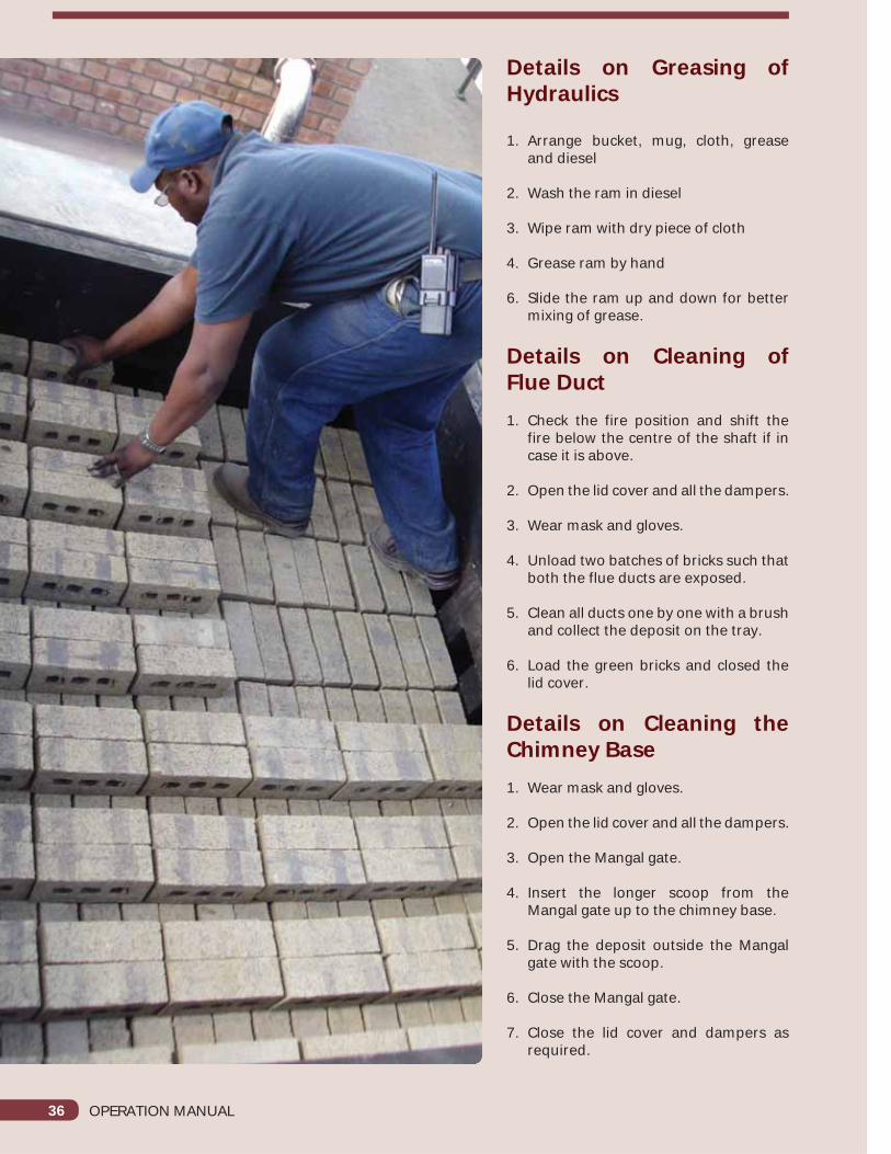
Details on Greasing of Hydraulics
1. Arrange bucket, mug, cloth, grease and diesel
2. Wash the ram in diesel
3. Wipe ram with dry piece of cloth
4. Grease ram by hand
6. Slide the ram up and down for better mixing of grease.
Details on Cleaning ofFlue Duct 1. Check the fire position and shift the
fire below the centre of the shaft if in case it is above.
2. Open the lid cover and all the dampers.
3. Wear mask and gloves.
4. Unload two batches of bricks such that both the flue ducts are exposed.
5. Clean all ducts one by one with a brush and collect the deposit on the tray.
6. Load the green bricks and closed the lid cover.
Details on Cleaning the Chimney Base1. Wear mask and gloves.
2. Open the lid cover and all the dampers.
3. Open the Mangal gate.
4. Insert the longer scoop from the Mangal gate up to the chimney base.
5. Drag the deposit outside the Mangal gate with the scoop.
6. Close the Mangal gate.
7. Close the lid cover and dampers as required.

OPERATION MANUAL 37
Chapter 14
Repair and Maintenance ina VSBK
Primary Responsibilities
1. Fire master manages materials such as coal, dry bricks for his kiln.
2. Fire master should assess the quality and quantity of the required materials, as well as the arrangement of the labour.
3. Fire master has to take quick decisions in terms of quality, quantity, material and labour.
4. Fire master has to mobilise and manage his labours smoothly.
5. Fire master should be able to perform minor maintenance and has to inform for major maintenance and repair work of the kin.
6. Fire master has to ensure that safety precautions are followed by his helpers, such as wearing gloves, helmet and mask, etc and has to follow the same.
7. Fire master has to maintain a log book in a logical manner.
8. Fire master has to motivate and supervise his helpers to perform better.
9. Fire master has to load and unload the bricks.
10. Fire master should be able to access the green brick’s quality, fired brick’s quality and the quality of the coal.
11. Fire master has to check the temperature of the kiln by thermo-couple and by the colour ofthe fire.
12. Fire master should be able to maintain fire at a consistent firing schedule.
Coal stacked
Weighing of coal

38 OPERATION MANUAL
13. Fire master is responsible for maintainingfire and deciding on the loading andunloading time.
14. Fire master should be able to make good relationship between his superiors and his subordinates.
Don’ts of a Fire Master
1. During the night shifts, if the fire master sleeps, the unloading of the bricks can be delayed. This can cause the shifting of firing in the pre-heating zone. Any fluctuations in the unloading time can cause poor quality of fired bricks.
2. Green bricks are stacked in the loading platform. The fire master sits on these stacks from time to time, causing breaks and cracks in the green bricks.
3. Poor quality and cracked bricks should notbe loaded.
4. Not using OHS (Occupational Health and Safety) materials such as helmet, gloves, andmasks, etc.
5. Not cleaning the loading platform and the shaft top from time to time.
6. While unloading a batch, the Fire Master should not hold the trolley on the hydraulics without resting it on the rail.
7. Should not go for a walk during the loading and unloading time.
8. Should not delay in stacking the unloaded fired bricks outside.
9. Not properly cleaning the coal ash, fallen on top of the I-beam. If the I-beams are not
Loading of green brick Uneven level due to improper loading
Damaged brick due to delayed unloading
OPERATION MANUAL 39
cleaned, the I-bar can’t rest properly on the I-beams because the coal ash on it damages the bricks.
10. Uneven and improper loading of green bricks should be avoided. Improper loading can increase the possibility of shaft jamming and lead to breakings of more bricks.
11. Not informing the person taking charge of loading, while unloading.
Primary Responsibilities of Entrepreneurs1. Prepare bricks that were specified as the design
basis for the VSBK.
2. Employ adequate number of trained staff for continuous operation
3. Use only recommended soil quality for green brick making.
4. Provide adequate number of dried green and fired bricks for initial fire stabilisation process.
5. Deploy fire masters and firemen to participate in theoretical and on-the-job training.
6. Participate in theoretical and on-the-job training on the firing process
7. Make frequent observations of the kiln and the brick yard.
8. Provide occupational health and safety facilities to all the workers.
Primary Responsibilities of Supervisors1. Monitor and supervise the operational
activities carefully, including the loading/unloading of bricks, monitoring of temperature curves etc.
2. Manage firing shifts and firing personnel
3. Monitor the performance of the firemaster/firemen
4. Check the attendance of firemen andthe firemaster
5. Cross check the log book, summarise and present the result to the entrepreneurs
6. Train new firemasters/firemen to operate the VSBK technology
7. Check the quality of green bricks and fired bricks
8. Enforce the use of safety equipment at work
9. Supervise the maintenance work and report to the entrepreneurs on major maintenance tasks, if required
10. Support the firemaster in troubleshooting activities

40 OPERATION MANUAL
Chapter 15
Some VSBK Common Issues During Operation
Loading of Green Bricks
Do’s
1. Load fully dried green bricks.
2. Load only good quality (shape/size/cracks) bricks.
3. Level the bricks in every layer.
4. Maintain the gap between the shaft wall and the brick surface.
5. Maintain the chula layer with a correct gap.
6. Load each brick individually
7. Load the bricks from the top.
8. Open both dampers.
9. Always wear a mask.
Don’ts
1. Don’t load bricks before unloading.
2. Don’t load green bricks above the shaft.
3. Don’t press the bricks tightly while loading in the shaft.
4. Don’t level the bricks using coal dust.
5. Don’t cut the bricks.
6. Don’t load bricks in a flat position in a chula layer.
7. Don’t load the bricks facing each other.
8. Don’t load the bricks in lumps.
9. Don’t change the stacking pattern unnecessarily.
10. Avoid cross loading of bricks.
Example of good loading
Cutting of bricks before loading

OPERATION MANUAL 41
Use of Thermo-CoupleDo’s:
1. Mark the end of thermo-couple to set the limit for insertion. (This mark will decide how much thermo-couple should be inserted into the peep-hole pipe).
2. Mark a distance of 2.5 m from the tip of the thermo-couple to set the limit and mark it.
3. Make a stopper at the end of the thermo-couple so that it does not get into the shaft.
4. Connect the thermo-couple with the scanner.
5. Connect the scanner with an electricity source.
6. Ensure a proper connection.
7. Take the readings 10 minutes after inserting the thermo-couple.
Don’ts:
1. Do not insert the thermo-couple beyond the marked limit.
2. Do not insert the thermo-couple irregularly.
3. Do not hit, hammer and smash the tip of the thermo-couple.
4. Do not take readings while the values are fluctuating in the scanner.
5. Avoid loose connections between wires.
6. Do not allow an open wire connection.
Maintaining of Log Book
1. When a log book is not maintained, it is really hard to find out the quantity of coal that has been consumed per batch.
2. When the amount of coal is not known it results into either over burned or under burned bricks.
3. It is difficult to decide the loading and unloading time, if the log book is not maintained.
4. If the log book is not maintained, we cannot find out the temperature of the kiln, which may result in a poor firing schedule.
5. Poor firing schedule leads to poor quality of bricks.
6. Production of bricks per day cannot be calculated.
7. Brick breakage rate cannot be calculated.
Monitoring of temperature
42 OPERATION MANUAL
8. Handing over the duty will be a complex job. It will be difficult for a new fire master to determine the quantity of coal to be used and to decide when to unload the fired bricks.
Shaft jamming
Do’s
1. Load the green bricks on top of the shaft to create the additional pressure for releasing the bricks inside the shaft. Stack at least 500 to 600 bricks on top.
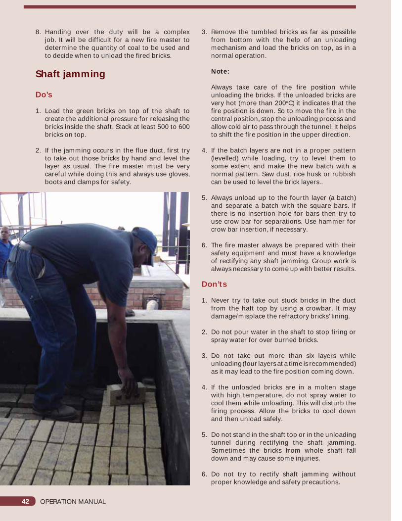
2. If the jamming occurs in the flue duct, first try to take out those bricks by hand and level the layer as usual. The fire master must be very careful while doing this and always use gloves, boots and clamps for safety.
3. Remove the tumbled bricks as far as possible from bottom with the help of an unloading mechanism and load the bricks on top, as in a normal operation.
Note:
Always take care of the fire position while unloading the bricks. If the unloaded bricks are very hot (more than 200oC) it indicates that the fire position is down. So to move the fire in the central position, stop the unloading process and allow cold air to pass through the tunnel. It helps to shift the fire position in the upper direction.
4. If the batch layers are not in a proper pattern (levelled) while loading, try to level them to some extent and make the new batch with a normal pattern. Saw dust, rice husk or rubbish can be used to level the brick layers..
5. Always unload up to the fourth layer (a batch) and separate a batch with the square bars. If there is no insertion hole for bars then try to use crow bar for separations. Use hammer for crow bar insertion, if necessary.
6. The fire master always be prepared with their safety equipment and must have a knowledge of rectifying any shaft jamming. Group work is always necessary to come up with better results.
Don’ts
1. Never try to take out stuck bricks in the duct from the haft top by using a crowbar. It may damage/misplace the refractory bricks’ lining.
2. Do not pour water in the shaft to stop firing or spray water for over burned bricks.
3. Do not take out more than six layers while unloading (four layers at a time is recommended) as it may lead to the fire position coming down.
4. If the unloaded bricks are in a molten stage with high temperature, do not spray water to cool them while unloading. This will disturb the firing process. Allow the bricks to cool down and then unload safely.
5. Do not stand in the shaft top or in the unloading tunnel during rectifying the shaft jamming. Sometimes the bricks from whole shaft fall down and may cause some injuries.
6. Do not try to rectify shaft jamming without proper knowledge and safety precautions.

Registered Office:B-32, TARA Crescent, Qutab Institutional Area,
New Delhi - 110 016, India