Embed Size (px)
Citation preview

NUREG-1123Revision 2 |
Knowledge and Abilities Catalogfor Nuclear Power Plant Operators:
Boiling Water Reactors
Manuscript Completed: June 5, 1998 |Date Published:
Operator Licensing and Human Performance BranchDivision of Reactor Controls and Human FactorsU.S. Nuclear Regulatory CommissionWashington, DC 20555

Back of cover

NUREG-1123, Rev. 2 |iii
ABSTRACT
The Knowledge and Abilities Catalog for Nuclear Power Plant Operators: Boiling Water Reactors(BWRs) (NUREG-1123, Revision 2) provides the basis for the development of content-valid |licensing examinations for reactor operators (ROs) and senior reactor operators (SROs). Theexaminations developed using the BWR Catalog along with the Operator Licensing Examination |Standards for Power Reactors (NUREG-1021, Rev. 8) will sample the topics listed under Title 10, |Code of Federal Regulations, Part 55 (10 CFR 55).
The BWR Catalog contains approximately 7,000 knowledge and ability (K/A) statements for ROs andSROs at BWRs. The catalog is organized into six major sections: Organization of the Catalog,Generic Knowledge and Ability Statements, Plant Systems grouped by Safety Functions, Emergencyand Abnormal Plant Evolutions, Components, and Theory.
Revision 1 to the BWR Catalog modified the form and content of the original catalog. The K/As were |linked to their applicable 10 CFR 55 item numbers. SRO level K/As were identified by 10 CFR55.43 item numbers. The plant-wide generic and system generic K/As were combined in one sectionwith approximately one hundred new K/As. Component Cooing Water and Instrument Air Systemswere added to the Systems Section. Finally, High Containment Hydrogen Concentration and PlantFire On Site evolutions added to the Emergency and Abnormal Plant Evolutions section.
Revision 2 incorporates corrections to the Rev. 1 catalog that were identified during a pilot testing |program associated with revision of 10 CFR 55 and implementation of NUREG-1021, Interim Rev. |8, “ Operator Licensing Examination Standards for Power Reactors.” Corrections to the catalog |include: |1. addition of 7 K/As that had been omitted in Rev. 1. |2. correction of typographical errors. |3. addition of importance value modifiers that had been omitted in Rev. 1. |Corrections and additions are identified by “redline” marking in the margins. |

NUREG-1123, Rev. 2 |iv
This page left blank

NUREG-1123, Rev. 2 |v
TABLE OF CONTENTS page ABSTRACT iii
SUMMARY OF SIGNIFICANT CHANGES xi
1 ORGANIZATION OF THE CATALOG
1.1 Introduction 1-11.2 Part 55 of Title 10 of the Code of Federal Regulations 1-11.3 RO Written Examination 1-11.4 SRO Written Examination 1-21.5 RO and SRO Operating Test Items |1-31.6 Senior Operators Limited to Fuel Handling 1-41.7 Organization of the BWR Catalog 1-41.8 Generic Knowledge and Abilities 1-51.9 Plant Systems 1-61.10 Emergency And Abnormal Plant Evolutions 1-101.11 Components 1-121.12 Theory 1-13 |1.13 Importance Ratings 1-13 |1.14 Acronyms And Terms 1-14 |
2 GENERIC KNOWLEDGE AND ABILITIES (132)
2.1 Conduct Of Operations 2-12.2 Equipment Control 2-52.3 Radiation Control 2-92.4 Emergency Procedures / Plan 2-10
3 PLANT SYSTEMS
3.1 Reactivity Control 3.1-1
Control Rod Drive Hydraulic System 3.1-3Control Rod and Drive Mechanism 3.1-7Reactor Manual Control System 3.1-10Recirculation Flow Control System 3.1-13Recirculation System 3.1-17Rod Control and Information System 3.1-22Standby Liquid Control System 3.1-25
NUREG-1123, Rev. 2 |vi
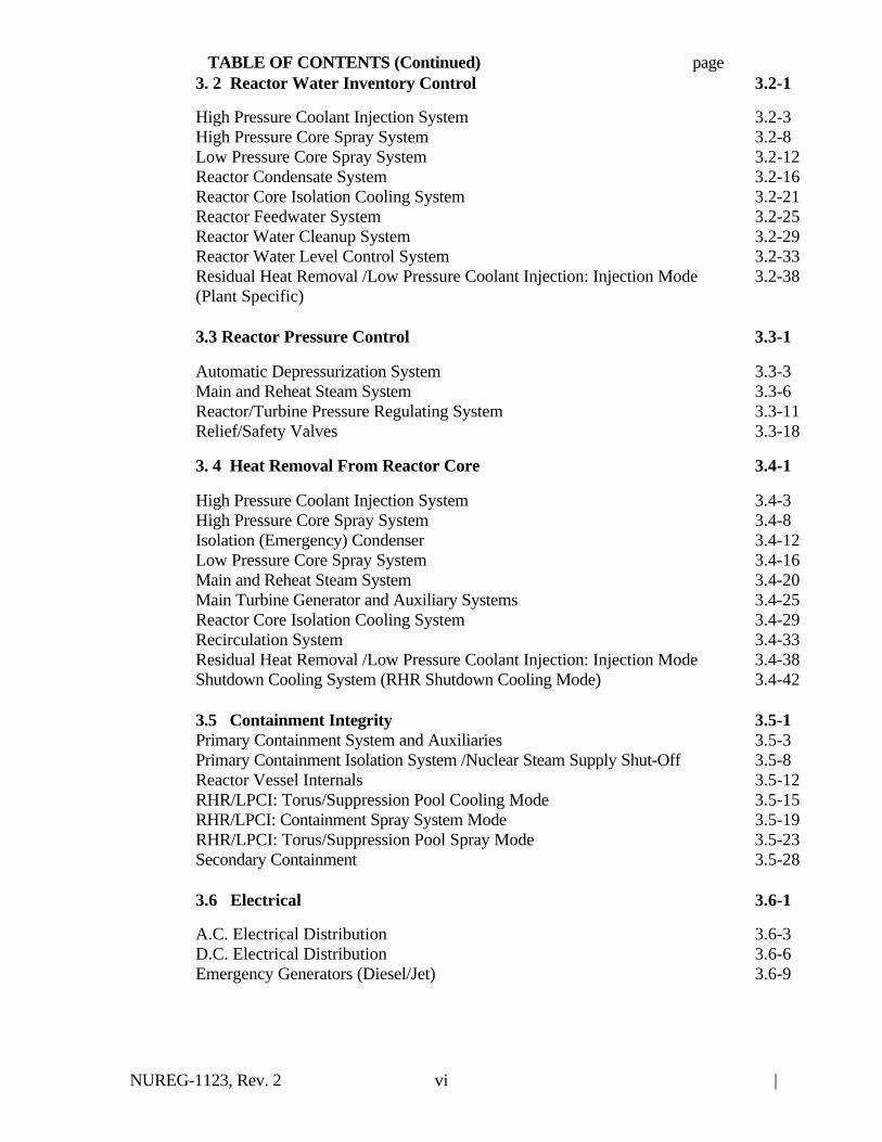
TABLE OF CONTENTS (Continued) page3. 2 Reactor Water Inventory Control 3.2-1
High Pressure Coolant Injection System 3.2-3High Pressure Core Spray System 3.2-8Low Pressure Core Spray System 3.2-12Reactor Condensate System 3.2-16Reactor Core Isolation Cooling System 3.2-21Reactor Feedwater System 3.2-25Reactor Water Cleanup System 3.2-29Reactor Water Level Control System 3.2-33Residual Heat Removal /Low Pressure Coolant Injection: Injection Mode(Plant Specific)
3.2-38
3.3 Reactor Pressure Control 3.3-1
Automatic Depressurization System 3.3-3Main and Reheat Steam System 3.3-6Reactor/Turbine Pressure Regulating System 3.3-11Relief/Safety Valves 3.3-18
3. 4 Heat Removal From Reactor Core 3.4-1
High Pressure Coolant Injection System 3.4-3High Pressure Core Spray System 3.4-8Isolation (Emergency) Condenser 3.4-12Low Pressure Core Spray System 3.4-16Main and Reheat Steam System 3.4-20Main Turbine Generator and Auxiliary Systems 3.4-25Reactor Core Isolation Cooling System 3.4-29Recirculation System 3.4-33Residual Heat Removal /Low Pressure Coolant Injection: Injection Mode 3.4-38Shutdown Cooling System (RHR Shutdown Cooling Mode) 3.4-42
3.5 Containment Integrity 3.5-1Primary Containment System and Auxiliaries 3.5-3Primary Containment Isolation System /Nuclear Steam Supply Shut-Off 3.5-8Reactor Vessel Internals 3.5-12RHR/LPCI: Torus/Suppression Pool Cooling Mode 3.5-15RHR/LPCI: Containment Spray System Mode 3.5-19RHR/LPCI: Torus/Suppression Pool Spray Mode 3.5-23Secondary Containment 3.5-28
3.6 Electrical 3.6-1
A.C. Electrical Distribution 3.6-3D.C. Electrical Distribution 3.6-6Emergency Generators (Diesel/Jet) 3.6-9
NUREG-1123, Rev. 2 |vii
TABLE OF CONTENTS (Continued) page
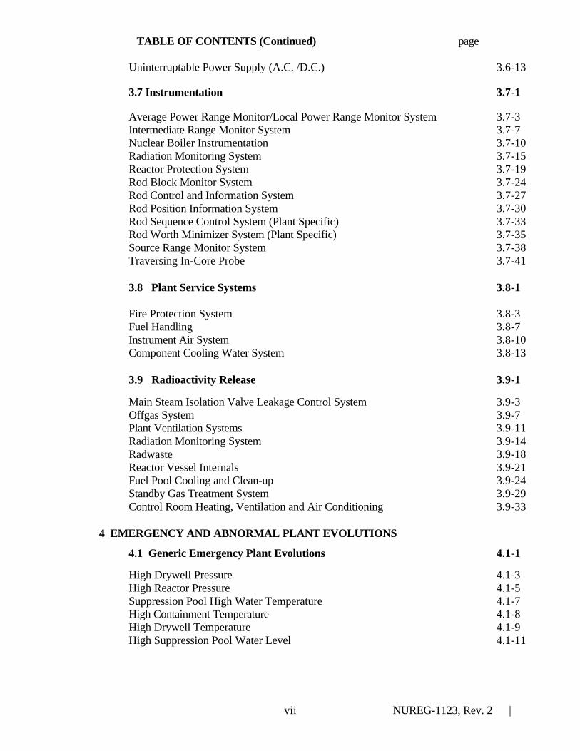
Uninterruptable Power Supply (A.C. /D.C.) 3.6-13
3.7 Instrumentation 3.7-1
Average Power Range Monitor/Local Power Range Monitor System 3.7-3Intermediate Range Monitor System 3.7-7Nuclear Boiler Instrumentation 3.7-10Radiation Monitoring System 3.7-15Reactor Protection System 3.7-19Rod Block Monitor System 3.7-24Rod Control and Information System 3.7-27Rod Position Information System 3.7-30Rod Sequence Control System (Plant Specific) 3.7-33Rod Worth Minimizer System (Plant Specific) 3.7-35Source Range Monitor System 3.7-38Traversing In-Core Probe 3.7-41
3.8 Plant Service Systems 3.8-1
Fire Protection System 3.8-3Fuel Handling 3.8-7Instrument Air System 3.8-10Component Cooling Water System 3.8-13
3.9 Radioactivity Release 3.9-1
Main Steam Isolation Valve Leakage Control System 3.9-3Offgas System 3.9-7Plant Ventilation Systems 3.9-11Radiation Monitoring System 3.9-14Radwaste 3.9-18Reactor Vessel Internals 3.9-21Fuel Pool Cooling and Clean-up 3.9-24Standby Gas Treatment System 3.9-29Control Room Heating, Ventilation and Air Conditioning 3.9-33
4 EMERGENCY AND ABNORMAL PLANT EVOLUTIONS
4.1 Generic Emergency Plant Evolutions 4.1-1
High Drywell Pressure 4.1-3High Reactor Pressure 4.1-5Suppression Pool High Water Temperature 4.1-7High Containment Temperature 4.1-8High Drywell Temperature 4.1-9High Suppression Pool Water Level 4.1-11
NUREG-1123, Rev. 2 |viii
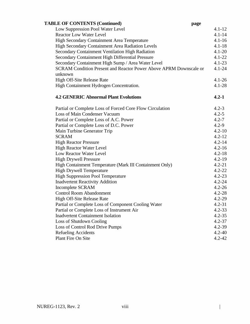
TABLE OF CONTENTS (Continued) pageLow Suppression Pool Water Level 4.1-12Reactor Low Water Level 4.1-14High Secondary Containment Area Temperature 4.1-16High Secondary Containment Area Radiation Levels 4.1-18Secondary Containment Ventilation High Radiation 4.1-20Secondary Containment High Differential Pressure 4.1-22Secondary Containment High Sump / Area Water Level 4.1-23SCRAM Condition Present and Reactor Power Above APRM Downscale orunknown
4.1-24
High Off-Site Release Rate 4.1-26High Containment Hydrogen Concentration. 4.1-28
4.2 GENERIC Abnormal Plant Evolutions 4.2-1
Partial or Complete Loss of Forced Core Flow Circulation 4.2-3Loss of Main Condenser Vacuum 4.2-5Partial or Complete Loss of A.C. Power 4.2-7Partial or Complete Loss of D.C. Power 4.2-9Main Turbine Generator Trip 4.2-10SCRAM 4.2-12High Reactor Pressure 4.2-14High Reactor Water Level 4.2-16Low Reactor Water Level 4.2-18High Drywell Pressure 4.2-19High Containment Temperature (Mark III Containment Only) 4.2-21High Drywell Temperature 4.2-22High Suppression Pool Temperature 4.2-23Inadvertent Reactivity Addition 4.2-24Incomplete SCRAM 4.2-26Control Room Abandonment 4.2-28High Off-Site Release Rate 4.2-29Partial or Complete Loss of Component Cooling Water 4.2-31Partial or Complete Loss of Instrument Air 4.2-33Inadvertent Containment Isolation 4.2-35Loss of Shutdown Cooling 4.2-37Loss of Control Rod Drive Pumps 4.2-39Refueling Accidents 4.2-40Plant Fire On Site 4.2-42

NUREG-1123, Rev. 2 |ix
TABLE OF CONTENTS (Continued) page5 COMPONENTS 5-1
Valves 5-3Sensors and Detectors 5-4Controllers and positioners 5-6Pumps 5-7Motors and Generators 5-9Heat Exchangers and Condensers 5-10Demineralizers and Ion Exchangers 5-11Breakers, Relays and Disconnects 5-12
6 THEORY 6.1-1
REACTOR THEORY 6.1-3 Neutrons 6.1-3
Neutron Life Cycle 6.1-4Reactor Kinetics and Neutron Sources 6.1-5Reactivity Coefficients 6.1-6Control rods 6.1-7Fission Product Poisons 6.1-8Fuel Depletion and Burnable Poisons 6.1-10Reactor Operational Physics 6.1-11
THERMODYNAMICS 6.2-1Thermodynamic Units and Properties 6.2-1Basic Energy Concepts 6.2-2Steam 6.2-3Thermodynamic Processes 6.2-4Thermodynamic Cycles 6.2-5Fluid Statics 6.2-6Heat Transfer and Heat Exchanges 6.2-8Thermal Hydraulics 6.2-9Core Thermal Limits 6.2-12Brittle Fracture and Vessel Thermal Stress 6.2-15

NUREG-1123, Rev. 2 |x
This page left blank

NUREG-1123, Rev. 2 |xi
SUMMARY OF SIGNIFICANT CHANGES
The changes described in paragraphs 1 through 6, below, were incorporated in Revision 1 of |the catalog in August, 1995. Paragraph 7 describes changes that are incorporated with |Revision 2 of the catalog. |
1 ORGANIZATION OF THE BWR CATALOG
1.1 The 10 CFR 55 items listed.
The content of the written examinations and operating licensing tests is dictated by Sections 55.41, |55.43, and 55.45 of Title 10 of the Code of Federal Regulations (10 CFR). The thirty four (34)items listed in 10 CFR 55 are listed in the catalog to reduce the need for cross referencing. |
1.2 Knowledge and Abilities linked to 10 CFR 55
The linkage of K/As to the 10 CFR 55.41, 43 and 45 requirements was done to help ensure that theexaminations include a representative sample from among the applicable items. Throughout the |catalog, 10 CFR 55 section references are shown in parentheses following the appropriate K/A |statement, such as (CFR: 41.x / 43.x / 45.x). |
1.3 Senior Reactor Operator (SRO) K/As identified
NUREG-1021, Rev. 8, "Operator Licensing Examination Standards for Power Reactors," Section |ES-401, requires at least 25% of the site-specific written examination for SROs to evaluate K/As |required for the higher license level. The original catalogs did not explicitly identify the K/As that |represented the higher license level. Differences in RO and SRO importance ratings weresometimes used, but, the rating differences were not linked to the 10 CFR 55.43 SRO items. In thiscatalog revision, SRO license level K/As were linked to the items associated with the 10 CFR55.43 SRO items. This is intended to remove subjectivity from selection of higher license levelK/As.
1.4 Senior Reactor Operator Limited to Fuel Handling (LSRO) examination specifications added.
NUREG-1021, Rev. 8 , Section 701 refers to the K/A catalog. In an effort to assure consistency |between the Examination Standards and the catalog, a brief discussion of the use of the catalog for |LSRO examinations was included.

NUREG-1123, Rev. 2 |xii
1.5 An updated catalog organization was implemented.
1. ORGANIZATION OF BWR CATALOG1. Added 10 CFR information
2 Generic Knowledge and Abilities1. Combined old plant-wide and system generic K/As in one section.2. Eliminated duplicate generic K/As.3. Organized the section into 4 topic areas.4. Added about 100 new generic K/As.
3 Plant Systems1. Moved System Generic K/As to new generic section2. Added Instrument Air System3. Added Component Cooling Water System
4 Emergency & Abnormal Plant Evolution Section1. Moved Generic K/As to Section 22. Added High Containment Hydrogen Concentration3. Added Plant Fire On Site
5 ComponentsNo change
6 Theory SectionNo change
NUREG-1123, Rev. 2 |xiii
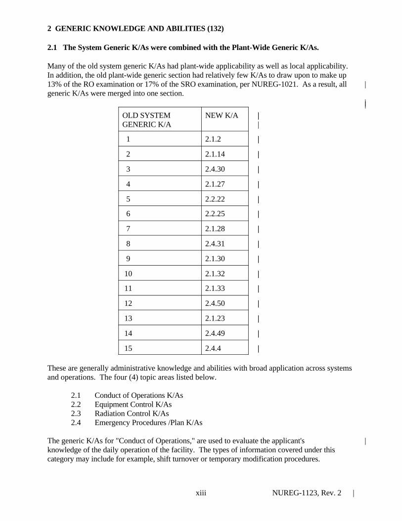
2 GENERIC KNOWLEDGE AND ABILITIES (132)
2.1 The System Generic K/As were combined with the Plant-Wide Generic K/As.
Many of the old system generic K/As had plant-wide applicability as well as local applicability. In addition, the old plant-wide generic section had relatively few K/As to draw upon to make up13% of the RO examination or 17% of the SRO examination, per NUREG-1021. As a result, all |generic K/As were merged into one section.
||OLD SYSTEM |GENERIC K/A |
NEW K/A |
1 |2.1.2 |
2 |2.1.14 |
3 |2.4.30 |
4 |2.1.27 |
5 |2.2.22 |
6 |2.2.25 |
7 |2.1.28 |
8 |2.4.31 |
9 |2.1.30 |
10 |2.1.32 |
11 |2.1.33 |
12 |2.4.50 |
13 |2.1.23 |
14 |2.4.49 |
15 |2.4.4 |
These are generally administrative knowledge and abilities with broad application across systemsand operations. The four (4) topic areas listed below.
2.1 Conduct of Operations K/As2.2 Equipment Control K/As2.3 Radiation Control K/As2.4 Emergency Procedures /Plan K/As
The generic K/As for "Conduct of Operations," are used to evaluate the applicant's |knowledge of the daily operation of the facility. The types of information covered under thiscategory may include for example, shift turnover or temporary modification procedures.

NUREG-1123, Rev. 2 |xiv
The generic K/As for "Equipment Control " are used to evaluate the administrative issues|associated with the management and control of plant systems and equipment. Examples of the typesof information evaluated under this topic include maintenance and temporary modifications ofsystems. Fuel handling and refueling K/As were also organized into this topic area because of theequipment control aspect of fuel handling.
The generic K/As for "Radiation Control," are used to evaluate the applicant's knowledge and|abilities with respect to radiation hazards and protection (personnel and public). Examples of thetypes of information that should be evaluated under this topic are knowledge of significantradiation hazards or radiation work permits.
The generic K/As for "Emergency Procedures / Plan" are used to evaluate the applicant's general|knowledge of emergency operations. The K/As are designed to evaluate knowledge of theemergency procedures use. The emergency plan K/As may be used to evaluate the applicant'sknowledge of the plan, including, as appropriate, the RO's or SRO's responsibility to decidewhether it should be executed and the duties assigned under the plan.
2.2 Approximately one hundred (100) new generic K/As were added to the catalog.
The new K/As were identified through license examiner surveys and an independent review of thecatalog, NUREG-1021, licensee event reports and inspection reports. All new K/As were directlylinked to the applicable 10 CFR 55 requirements.
3 PLANT SYSTEMS (56) WITHIN 9 SAFETY FUNCTIONS
3.1 The old system generic K/As were combined with plant wide generic K/As in Section 2, Generic K/As.
3.2 Two systems were added because they were covered in the Abnormal Evolutions.1. Instrument Air System2. Component Cooling Water System
3.3 K/A stem statement K5, changed “operational applications” to “operational implications”
4 EMERGENCY & ABNORMAL PLANT EVOLUTIONS (40)
4.1 The original system generic K/As were combined with plant wide generic K/As in|Section 2, Generic K/As. Duplicate generic K/As were combined into single K/As whereapplicable.
4.2. High Containment Hydrogen Concentration was added to reflect Revision 4 changesto BWROG Emergency Procedures Guidelines (EPGs).
4.3 Plant Fire On Site was added as an abnormal plant evolution to achieve consistencywith the Fire Protection System section.

NUREG-1123, Rev. 2 |xv
4.4 Emergency and Abnormal Evolution K/As were linked to 10 CFR 55 item numbers at |the stem statement level.
5 COMPONENTS
5.1 All component K/As were linked to 10 CFR 55 item numbers. |
6 THEORY
6.1 Reactor Theory and Thermodynamics theory K/As were linked to 10 CFR, 55 item |numbers.
7 REVISION 2 CHANGES ||
7.1 Approximately 7 K/As that had been omitted in Rev. 1 were added. |7.2 Typographical errors were corrected. |7.3 Importance value modifiers that had been omitted in Rev. 1 were added. |Corrections and additions are identified by “redline” marking in the margins. |
|

NUREG-1123, Rev. 2 |1.1
1 ORGANIZATION OF THE CATALOG
1.1 INTRODUCTION
The Knowledge and Abilities Catalog for Nuclear Power Plant Operators: Boiling Water Reactors(BWR) NUREG-1123, Revision 2, provides the basis for development of content-valid written |and operating licensing examinations for reactor operators (ROs) and senior reactor operators(SROs). The Catalog is designed to ensure equitable and consistent examinations.
1.2 PART 55 OF TITLE 10 OF THE CODE OF FEDERAL REGULATIONS
The catalog is used in conjunction with NUREG-1021, Revision 8 "Operator Licensing |Examination Standards for Power Reactors." NUREG-1021 provides policy and guidance and |establishes the procedures and practices for examining licensees and applicants for RO and SROlicenses pursuant to Part 55 of Title 10 of the Code of Federal Regulations (10 CFR 55). Allknowledge and abilities (K/As) in this catalog are directly linked by item number to 10 CFR 55.
1.3 RO WRITTEN EXAMINATION
The items for RO written examinations are specified in 10 CFR 55.41(b). The RO writtenexamination questions should be generated from a representative sample of K/As derived fromamong the 10 CFR 55.41(b) items listed below:
(1) Fundamentals of reactor theory, including fission process, neutron multiplication, sourceeffects, control rod effects, criticality indications, reactivity coefficients, and poisoneffects.
(2) General design features of the core, including core structure, fuel elements, control rods,core instrumentation, and coolant flow.
(3) Mechanical components and design features of reactor primary system.
(4) Secondary coolant and auxiliary systems that affect the facility.

NUREG-1123, Rev. 2 |1.2
(5) Facility operating characteristics during steady state and transient conditions, includingcoolant chemistry, causes and effects of temperature, pressure and reactivity changes,effects of load changes, and operating limitations and reasons for these operatingcharacteristics.
(6) Design, components, and function of reactivity control mechanisms and instrumentation.
(7) Design, components, and function of control and safety systems, including instrumentation,signals, interlocks, failure modes, and automatic and manual features.
(8) Components, capacity, and functions of emergency systems.
(9) Shielding, isolation, and containment design features, including access limitations.
(10) Administrative, normal, abnormal, and emergency operating procedures for the facility.
(11) Purpose and operation of radiation monitoring systems, including alarms and surveyequipment.
(12) Radiological safety principles and procedures.
(13) Procedures and equipment available for handling and disposal of radioactive materials andeffluents.
(14) Principals of heat transfer, thermodynamics and fluid mechanics.
The RO written examination is administered in two sections, a generic fundamentals examination(GFE) section and a site-specific examination. The GFE covers those knowledge items that do not|vary significantly among reactors of the same type (refer to NUREG-1021, ES-205). The GFE|covers components, reactor theory, and thermodynamics knowledge. The component knowledgeitems are derived from 10 CFR 55.41(b) items 3 and 7. Reactor theory knowledge items arederived from 10 CFR 55.41(b)1. Thermodynamic knowledge items are derived from 10 CFR55.41(b)14.
The site-specific RO written examination covers K/As that vary among reactors of the same type. The guidance for preparation of RO written examination is presented in NUREG-1021, ES-401. |The RO examination includes a balanced mix of generic K/As, plant systems K/As, andemergency/abnormal evolution K/As. The K/As associated with the RO site-specific writtenexaminations are derived from 10 CFR 55.41(b) items 2 through 13.
1.4 SRO WRITTEN EXAMINATION
The items for SRO written examinations are presented in 10 CFR 55.43(b). The guidance for
NUREG-1123, Rev. 2 |1.3
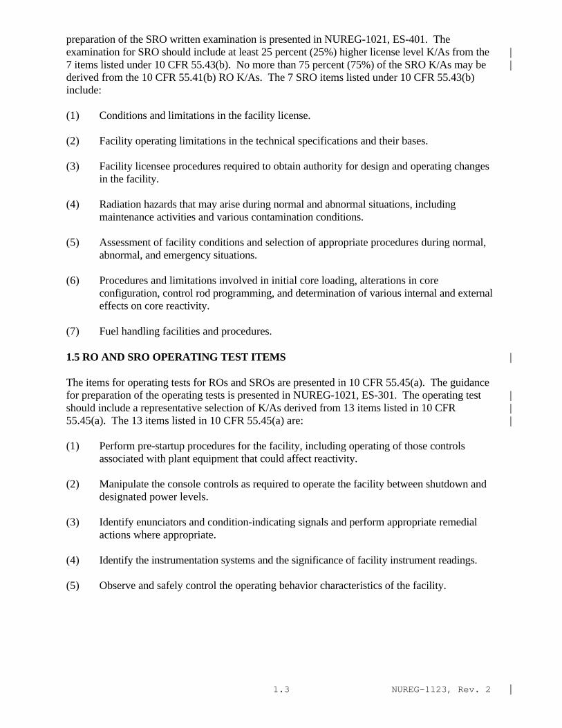
preparation of the SRO written examination is presented in NUREG-1021, ES-401. Theexamination for SRO should include at least 25 percent (25%) higher license level K/As from the |7 items listed under 10 CFR 55.43(b). No more than 75 percent (75%) of the SRO K/As may be |derived from the 10 CFR 55.41(b) RO K/As. The 7 SRO items listed under 10 CFR 55.43(b)include:
(1) Conditions and limitations in the facility license.
(2) Facility operating limitations in the technical specifications and their bases.
(3) Facility licensee procedures required to obtain authority for design and operating changesin the facility.
(4) Radiation hazards that may arise during normal and abnormal situations, includingmaintenance activities and various contamination conditions.
(5) Assessment of facility conditions and selection of appropriate procedures during normal,abnormal, and emergency situations.
(6) Procedures and limitations involved in initial core loading, alterations in coreconfiguration, control rod programming, and determination of various internal and externaleffects on core reactivity.
(7) Fuel handling facilities and procedures.
1.5 RO AND SRO OPERATING TEST ITEMS |
The items for operating tests for ROs and SROs are presented in 10 CFR 55.45(a). The guidancefor preparation of the operating tests is presented in NUREG-1021, ES-301. The operating test |should include a representative selection of K/As derived from 13 items listed in 10 CFR |55.45(a). The 13 items listed in 10 CFR 55.45(a) are: |
(1) Perform pre-startup procedures for the facility, including operating of those controlsassociated with plant equipment that could affect reactivity.
(2) Manipulate the console controls as required to operate the facility between shutdown anddesignated power levels.
(3) Identify enunciators and condition-indicating signals and perform appropriate remedialactions where appropriate.
(4) Identify the instrumentation systems and the significance of facility instrument readings.
(5) Observe and safely control the operating behavior characteristics of the facility.

NUREG-1123, Rev. 2 |1.4
(6) Perform control manipulations required to obtain desired operating results during normal,abnormal, and emergency situations.
(7) Safely operate the facility's heat removal systems, including primary coolant, emergencycoolant, and decay heat removal systems, and identify the relations of proper operation ofthese systems to the operation of the facility.
(8) Safety operate the facility's auxiliary and emergency systems, including operation of thosecontrols associated with plant equipment that could affect reactivity or the release ofradioactive materials to the environment
(9) Demonstrate or describe the use and function of the facility's radiation monitoring systems,including fixed radiation monitors and alarms, portable survey instruments, and personnelmonitoring equipment.
(10) Demonstrate a knowledge of significant radiation hazards, including permissible levels inexcess of those authorized, and ability to perform other procedures to reduce excessivelevels of radiation and to guard against personnel exposure.
(11) Demonstrate knowledge of the emergency plan for the facility, including, as appropriate,the operator's or senior operator's responsibility to decide when the plan should beexecuted and the duties under the plan assigned.
(12) Demonstrate the knowledge and ability as appropriate to the assigned position to assumethe responsibilities associated with the safe operation of the facility.
(13) Demonstrate the applicant's ability to function within the control room team as appropriateto the assigned position, in such a way that the facility licensee’s procedures are adhered toand that the limitations in its license and amendments are not violated.
1.6 SENIOR OPERATORS LIMITED TO FUEL HANDLING
The specifications for examinations for Senior Operators Limited to Fuel Handling (LSRO) areprovided in Examination Standard, NUREG 1021, Section ES-701. The LSRO examination|process includes both a written examination and an operating test. This examination and test|include, but are not limited to, items associated with 10 CFR 55.43(b) items 5 through 7, and 10|CFR 55.45(a) items 5 and 6.
1.7 ORGANIZATION OF THE BWR CATALOG
The Knowledge and Abilities Catalog for Nuclear Power Plant Operators: Boiling Water Reactorsis organized into 6 major sections. Knowledge and ability statements (K/As) are grouped|according to the major section to which they pertain. This organization is shown schematicallybelow.

NUREG-1123, Rev. 2 |1.5
1 ORGANIZATION OF THE BWR CATALOG
2 GENERIC KNOWLEDGE AND ABILITIES (132)Conduct of Operations K/AsEquipment Control K/AsRadiation Control K/AsEmergency Procedures / Plan K/As
3 PLANT SYSTEMS (56) WITHIN 9 SAFETY FUNCTIONSKnowledge Categories (K1 - K6)Ability Categories (A1 - A4)
4 EMERGENCY & ABNORMAL PLANT EVOLUTIONS (40)Knowledge Categories (E/A K1 - E/A K3)Ability Categories (E/A A1 - E/A - A2)
5 COMPONENTSComponent Knowledge Categories (8)
6 THEORYReactor Theory Knowledge Categories (8)Thermodynamics Knowledge Categories (10)
1.8 GENERIC KNOWLEDGE AND ABILITIES
Generic knowledge and abilities are generally administrative knowledges and abilities with broad |application across systems and operations. They are listed in Section 2 of the catalog. The four(4) categories of generic K/As are listed below:
1 Conduct of Operations K/As2 Equipment Control K/As3 Radiation Control K/As4 Emergency Procedures /Plan K/As
The generic K/As for "Conduct of Operations," are used to evaluate the applicant's |knowledge of the daily operation of the facility. The types of information covered under thiscategory may include for example, shift turnover or temporary modification procedures.
The generic K/As for "Equipment Control " are used to evaluate the administrative requirements |associated with the management and control of plant systems and equipment. Examples of the typesof information evaluated under this topic include maintenance and temporary modifications ofsystems.
The generic K/As for "Radiation Control" are used to evaluate the applicant's knowledge and |abilities with respect to radiation hazards and protection (personnel and public). Examples of
NUREG-1123, Rev. 2 |1.6
the types of information that should be evaluated under this topic are knowledge of significantradiation hazards or radiation work permits.
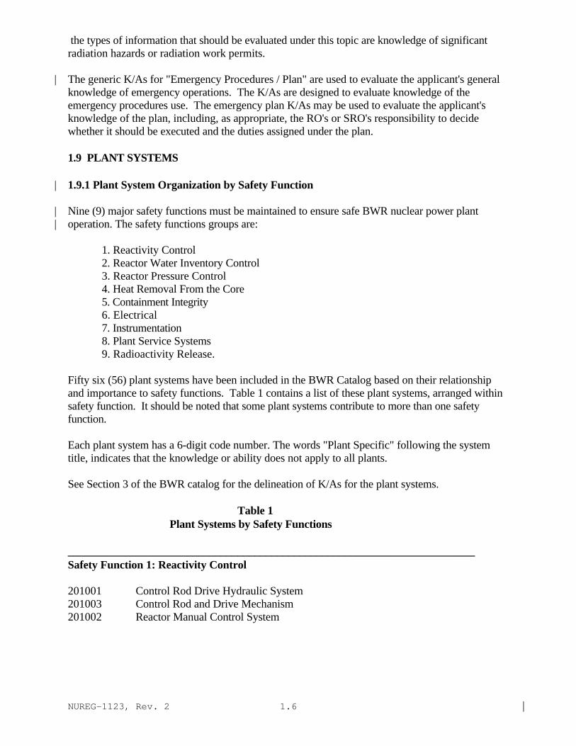
The generic K/As for "Emergency Procedures / Plan" are used to evaluate the applicant's general|knowledge of emergency operations. The K/As are designed to evaluate knowledge of theemergency procedures use. The emergency plan K/As may be used to evaluate the applicant'sknowledge of the plan, including, as appropriate, the RO's or SRO's responsibility to decidewhether it should be executed and the duties assigned under the plan.
1.9 PLANT SYSTEMS
1.9.1 Plant System Organization by Safety Function|
Nine (9) major safety functions must be maintained to ensure safe BWR nuclear power plant|operation. The safety functions groups are:|
1. Reactivity Control2. Reactor Water Inventory Control3. Reactor Pressure Control4. Heat Removal From the Core5. Containment Integrity6. Electrical7. Instrumentation8. Plant Service Systems9. Radioactivity Release.
Fifty six (56) plant systems have been included in the BWR Catalog based on their relationshipand importance to safety functions. Table 1 contains a list of these plant systems, arranged withinsafety function. It should be noted that some plant systems contribute to more than one safetyfunction.
Each plant system has a 6-digit code number. The words "Plant Specific" following the systemtitle, indicates that the knowledge or ability does not apply to all plants.
See Section 3 of the BWR catalog for the delineation of K/As for the plant systems.
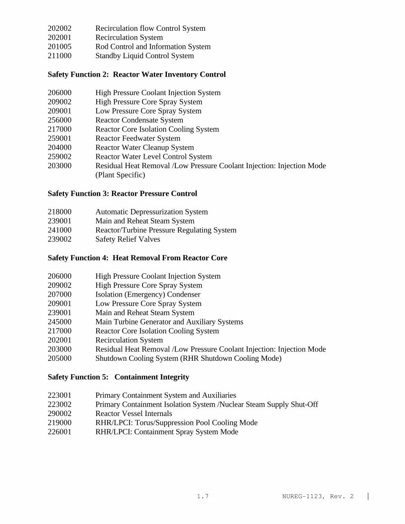
Table 1Plant Systems by Safety Functions
________________________________________________________________________Safety Function 1: Reactivity Control
201001 Control Rod Drive Hydraulic System201003 Control Rod and Drive Mechanism201002 Reactor Manual Control System
NUREG-1123, Rev. 2 |1.7
202002 Recirculation flow Control System202001 Recirculation System201005 Rod Control and Information System211000 Standby Liquid Control System
Safety Function 2: Reactor Water Inventory Control
206000 High Pressure Coolant Injection System209002 High Pressure Core Spray System209001 Low Pressure Core Spray System256000 Reactor Condensate System217000 Reactor Core Isolation Cooling System259001 Reactor Feedwater System204000 Reactor Water Cleanup System259002 Reactor Water Level Control System203000 Residual Heat Removal /Low Pressure Coolant Injection: Injection Mode
(Plant Specific)
Safety Function 3: Reactor Pressure Control
218000 Automatic Depressurization System239001 Main and Reheat Steam System241000 Reactor/Turbine Pressure Regulating System239002 Safety Relief Valves
Safety Function 4: Heat Removal From Reactor Core
206000 High Pressure Coolant Injection System209002 High Pressure Core Spray System207000 Isolation (Emergency) Condenser209001 Low Pressure Core Spray System239001 Main and Reheat Steam System245000 Main Turbine Generator and Auxiliary Systems217000 Reactor Core Isolation Cooling System202001 Recirculation System203000 Residual Heat Removal /Low Pressure Coolant Injection: Injection Mode205000 Shutdown Cooling System (RHR Shutdown Cooling Mode)
Safety Function 5: Containment Integrity
223001 Primary Containment System and Auxiliaries223002 Primary Containment Isolation System /Nuclear Steam Supply Shut-Off290002 Reactor Vessel Internals219000 RHR/LPCI: Torus/Suppression Pool Cooling Mode226001 RHR/LPCI: Containment Spray System Mode

NUREG-1123, Rev. 2 |1.8
230000 RHR/LPCI: Torus/Suppression Pool Spray Mode290001 Secondary Containment
Safety Function 6: Electrical
262001 A.C. Electrical Distribution263000 D.C. Electrical Distribution264000 Emergency Generators (Diesel/Jet)262002 Uninterruptable Power Supply (A.C. /D.C.)
Safety Function 7: Instrumentation
215005 Average Power Range Monitor/Local Power Range Monitor215003 Intermediate Range Monitor System216000 Nuclear Boiler Instrumentation272000 Radiation Monitoring System212000 Reactor Protection System215002 Rod Block Monitor System201005 Rod Control and Information System214000 Rod Position Information System201004 Rod Sequence Control System (Plant Specific)201006 Rod Worth Minimizer System (Plant Specific)215004 Source Range Monitor System215001 Traversing In-Core Probe
Safety Function 8: Plant Service Systems
286000 Fire Protection System234000 Fuel Handling300000 Instrument Air System400000 Component Cooling Water System
Safety Function 9: Radioactivity Release
239003 Main Steam Isolation Valve Leakage Control System271000 Offgas System288000 Plant Ventilation Systems272000 Radiation Monitoring System268000 Radwaste290002 Reactor Vessel Internals233000 Fuel Pool Cooling and Clean-up261000 Standby Gas Treatment System290003 Control Room Heating, Ventilation and Air Conditioning

NUREG-1123, Rev. 2 |1.9
1.9.2 Knowledge and Ability Stem Statements for Plant Systems |
The information delineated within each plant system is organized into 6 different types ofknowledge and 4 different types of ability. If there are no knowledge or ability statementsfollowing a stem statement there is no applicable K/A.
The applicable 10 CFR 55.41 / 43 / and 45 item numbers are included with each stem statement. In most cases the K/As associated with the stem statements can be used for both the writtenexamination and the operating test. See Table 2 below: |
Table 2Knowledge and Ability Stem Statements for Plant Systems
K1. Knowledge of the physical connections and/or cause-effect relationshipsbetween (SYSTEM) and the following:(CFR: 41.2 to 41.9 / 45.7 to 45.8)
K2. Knowledge of electrical power supplies to the following:(CFR: 41.7)
K3. Knowledge of the effect that a loss or malfunction of the (SYSTEM) willhave on the following:(CFR: 41.7 / 45.4)
K4. Knowledge of (SYSTEM) design feature(s) and or interlock(s) which providefor the following:(CFR: 41.7)
K5. Knowledge of the operational implications of the following concepts asthey apply to the (SYSTEM):(CFR: 41.5 / 45.3)
K6 Knowledge of the effect that a loss or malfunction of the following willhave on the (SYSTEM):(CFR: 41.7 / 45.7)
A1. Ability to predict and/or monitor changes in parameters associated withoperating the (SYSTEM) controls including:(CFR: 41.5 / 45.5)
A2. Ability to (a) predict the impacts of the following on the (SYSTEM) and(b) based on those predictions, use procedures to correct, control, ormitigate the consequences of those abnormal operation:(CFR: 41.5 / 45.6)

NUREG-1123, Rev. 2 |1.10
A3. Ability to monitor automatic operations of the (SYSTEM) including:(CFR: 41.7 / 45.7)
A4. Ability to manually operate and/or monitor in the control room:(CFR: 41.7 / 45.5 to 45.8)
1.10 EMERGENCY & ABNORMAL PLANT EVOLUTIONS
Section 4 of the BWR catalog contains emergency plant evolutions (EPEs) and abnormal plant|evolutions (APEs). An emergency plant evolution is any condition, event or symptom which leads|to entry into the plant-specific emergency operating procedures (EOPs). An abnormal plant|evolution is any degraded condition, event or symptom not directly leading to an EOP entry|condition, but, nontheless, adversely affecting a safety function. The listing of EPEs and APEs|was developed to include those integrative situations crossing several plant systems and/or safety|functions. |
The emergency plant evolution strategies described in Revision 4 to the Boiling Water ReactorOwners Group Emergency Procedures Guidelines, cover five broad areas:
1) Reactor Pressure Vessel Control2) Reactor Pressure Vessel Control With SCRAM Condition Present and Reactor
Power Above APRM Downscale or Unknown.3) Primary Containment Control4) Secondary Containment Control5) Radioactivity Release Control.
If the operator controls the five broad areas of emergency plant evolutions listed above, the plantsafety functions will be safely maintained. Table 3, below, contains a numerical list of the 16|emergency plant evolutions and the 24 abnormal plant evolutions covered by this catalog.|
Table 3|Emergency and Abnormal Plant Evolutions|
EPEs|
295024 High Drywell Pressure295025 High Reactor Pressure295026 Suppression Pool High Water Temperature295027 High Containment Temperature (Mark III Containment Only)295028 High Drywell Temperature295029 High Suppression Pool Water Level295030 Low Suppression Pool Water Level295031 Reactor Low Water Level295032 High Secondary Containment Area Temperature

NUREG-1123, Rev. 2 |1.11
295033 High Secondary Containment Area Radiation Levels295034 Secondary Containment Ventilation High Radiation295035 Secondary Containment High Differential Pressure295036 Secondary Containment High Sump / Area Water Level295037 SCRAM Condition Present and Reactor Power Above APRM Downscale
or unknown295038 High Off-Site Release Rate500000 High Containment Hydrogen Concentration.
APEs |
295001 Partial or Complete Loss of Forced Core Flow Circulation295002 Loss of Main Condenser Vacuum295003 Partial or Complete Loss of A.C. Power295004 Partial or Complete Loss of D.C. Power295005 Main Turbine Trip295006 SCRAM295007 High Reactor Pressure295008 High Reactor Water Level295009 Low Reactor Water Level295010 High Drywell Pressure295011 High Containment Temperature (Mark III Containment Only)295012 High Drywell Temperature295013 High Suppression Pool Water Temperature295014 Inadvertent Reactivity Addition295015 Incomplete SCRAM295016 Control Room Abandonment295017 High Off-Site Release Rate295018 Partial or Complete Loss of Component Cooling Water295019 Partial or Complete Loss of Instrument Air295020 Inadvertent Containment Isolation295021 Loss of Shutdown Cooling295022 Loss of Control Rod Drive Pumps295023 Refueling Accidents600000 Plant Fire On Site
1.10.1 Knowledge and Ability Stem Statements for Emergency and Abnormal Plant Evolutions
The information delineated within each emergency or abnormal evolution is organized into three(3)different types of knowledge and two (2) different types of ability. If there are no knowledge orability statements following a stem statement there is no applicable K/A.
The applicable 10 CFR 55.41, 43, and 45 item numbers are included with each stem statement. Inmost cases the K/As associated with the stem statements can be used for both
NUREG-1123, Rev. 2 |1.12
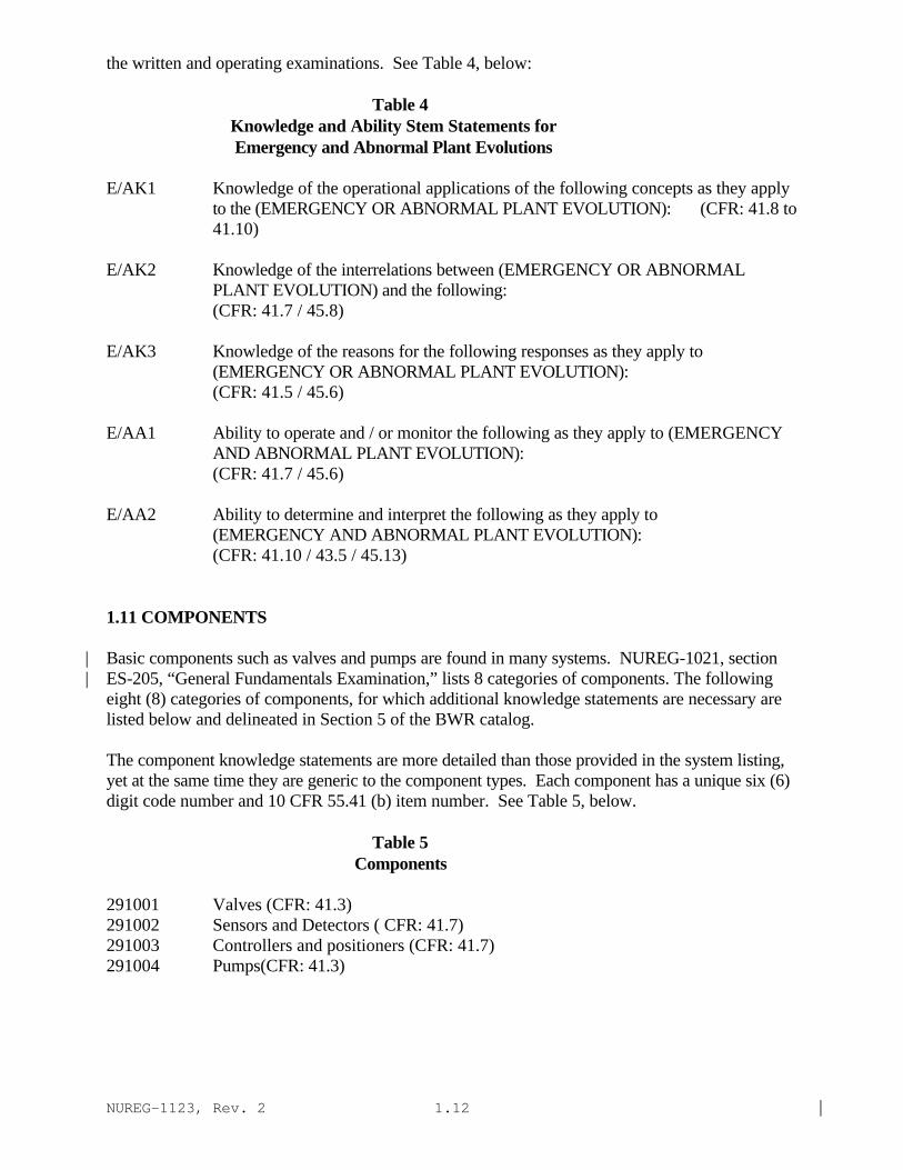
the written and operating examinations. See Table 4, below:
Table 4 Knowledge and Ability Stem Statements for Emergency and Abnormal Plant Evolutions
E/AK1 Knowledge of the operational applications of the following concepts as they applyto the (EMERGENCY OR ABNORMAL PLANT EVOLUTION): (CFR: 41.8 to41.10)
E/AK2 Knowledge of the interrelations between (EMERGENCY OR ABNORMAL PLANT EVOLUTION) and the following: (CFR: 41.7 / 45.8)
E/AK3 Knowledge of the reasons for the following responses as they apply to (EMERGENCY OR ABNORMAL PLANT EVOLUTION): (CFR: 41.5 / 45.6)
E/AA1 Ability to operate and / or monitor the following as they apply to (EMERGENCY AND ABNORMAL PLANT EVOLUTION): (CFR: 41.7 / 45.6)
E/AA2 Ability to determine and interpret the following as they apply to (EMERGENCY AND ABNORMAL PLANT EVOLUTION): (CFR: 41.10 / 43.5 / 45.13)
1.11 COMPONENTS
Basic components such as valves and pumps are found in many systems. NUREG-1021, section|ES-205, “General Fundamentals Examination,” lists 8 categories of components. The following|eight (8) categories of components, for which additional knowledge statements are necessary arelisted below and delineated in Section 5 of the BWR catalog.
The component knowledge statements are more detailed than those provided in the system listing,yet at the same time they are generic to the component types. Each component has a unique six (6)digit code number and 10 CFR 55.41 (b) item number. See Table 5, below.
Table 5 Components
291001 Valves (CFR: 41.3)291002 Sensors and Detectors ( CFR: 41.7)291003 Controllers and positioners (CFR: 41.7)291004 Pumps(CFR: 41.3)

NUREG-1123, Rev. 2 |1.13
291005 Motors and Generators (CFR: 41.7)291006 Heat Exchangers and Condensers (CFR: 41.4) |291007 Demineralizers and Ion Exchangers ( CFR: 41.3) |291008 Breakers, Relays and Disconnects (CFR: 41.7) |
1.12 THEORY
NUREG-1021, Section ES-205, “General Fundamentals Examination,” lists | theory items. General fundamental knowledge which underlies safe performance on the job is |delineated in Section 6 of the BWR Catalog. These theory topics represent general fundamentalconcepts related to plant operation. Each theory topic has a unique six (6) digit code number. Theapplicable 10 CFR 41(b) item number is provided for Reactor Theory and ThermodynamicsTheory.
Reactor Theory (CFR: 41.1)
292001 Neutrons292002 Neutron Life Cycle292003 Reactor Kinetics and Neutron Sources292004 Reactivity Coefficients292005 Control rods292006 Fission Product Poisons292007 Fuel Depletion and Burnable Poisons292008 Reactor Operational Physics
Thermodynamics Theory (CFR: 41.14)
293001 Thermodynamic Units and Properties293002 Basic Energy Concepts293003 Steam293004 Thermodynamic Process293005 Thermodynamic Cycles293006 Fluid Statics293007 Heat Transfer and Heat Exchangers293008 Thermal Hydraulics293009 Core Thermal Limits293010 Brittle Fracture and Vessel Thermal Stress
1.13 IMPORTANCE RATINGS
Importance, in this context, considers direct and indirect impact of the K/A on safe plant operation |in a manner ensuring personnel and public health and safety. Importance Ratings of the K/As aregiven for Reactor Operators and Senior Reactor Operators next to each knowledge and ability inthe catalog. These ratings reflect average ratings of individual NRC and utility panel members. The rating scale is presented in Table 6, below. |
NUREG-1123, Rev. 2 |1.14
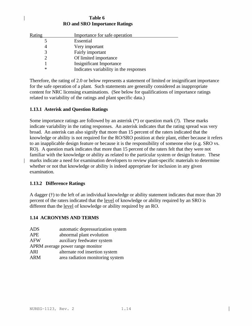
Table 6| RO and SRO Importance Ratings
Rating Importance for safe operation5 Essential4 Very important3 Fairly important2 Of limited importance1 Insignificant Importance* Indicates variability in the responses
Therefore, the rating of 2.0 or below represents a statement of limited or insignificant importancefor the safe operation of a plant. Such statements are generally considered as inappropriatecontent for NRC licensing examinations. (See below for qualifications of importance ratingsrelated to variability of the ratings and plant specific data.)
1.13.1 Asterisk and Question Ratings
Some importance ratings are followed by an asterisk (*) or question mark (?). These marksindicate variability in the rating responses. An asterisk indicates that the rating spread was verybroad. An asterisk can also signify that more than 15 percent of the raters indicated that theknowledge or ability is not required for the RO/SRO position at their plant, either because it refersto an inapplicable design feature or because it is the responsibility of someone else (e.g. SRO vs.RO). A question mark indicates that more than 15 percent of the raters felt that they were notfamiliar with the knowledge or ability as related to the particular system or design feature. Thesemarks indicate a need for examination developers to review plant-specific materials to determine|whether or not that knowledge or ability is indeed appropriate for inclusion in any givenexamination.
1.13.2 Difference Ratings
A dagger (†) to the left of an individual knowledge or ability statement indicates that more than 20percent of the raters indicated that the level of knowledge or ability required by an SRO isdifferent than the level of knowledge or ability required by an RO.
1.14 ACRONYMS AND TERMS
ADS automatic depressurization systemAPE abnormal plant evolutionAFW auxiliary feedwater systemAPRM average power range monitorARI alternate rod insertion systemARM area radiation monitoring system

NUREG-1123, Rev. 2 |1.15
ACRONYMS AND TERMS (continued)
ATWS anticipated transient without scramCFR code of federal regulationsCRD control rod driveD/G diesel generatorECCS emergency core cooling systemEPE emergency plant evolutionHPCS high pressure core sprayHVAC heating, ventilation and air conditioningIAS instrument air systemIRM intermediate range monitorK/A knowledge and abilityLCO limiting condition for operationLPCI low pressure coolant injectionLPCS low pressure core sprayLSRO senior reactor operator limited to fuel handlingMFW main feedwaterM/G motor generatorMSIV main steam isolation valveRCIC reactor coolant isolation systemRCS reactor coolant systemRHR residual heat removalRO reactor operatorRPS reactor protection systemRPV reactor pressure vesselSRO senior reactor operatorSRV safety relief valve

NUREG-1123, Rev. 2 |2-1
2.0 GENERIC KNOWLEDGES AND ABILITIES
2.1 Conduct of Operations
2.1.1 Knowledge of conduct of operations requirements. (CFR: 41.10 / 45.13)IMPORTANCE RO 3.7 SRO 3.8
2.1.2 Knowledge of operator responsibilities during all modes of plant operation. (CFR: 41.10 / 45.13)IMPORTANCE RO 3.0 SRO 4.0
2.1.3 Knowledge of shift turnover practices.
(CFR: 41.10 / 45.13)IMPORTANCE RO 3.0 SRO 3.4
2.1.4 Knowledge of shift staffing requirements. (CFR: 41.10 / 43.2)IMPORTANCE RO 2.3 SRO 3.4
2.1.5 Ability to locate and use procedures and directives related to shift staffing and activities.
(CFR: 41.10 / 43.5 / 45.12)IMPORTANCE RO 2.3 SRO 3.4
2.1.6 Ability to supervise and assume a management role during plant transients and upset conditions.
(CFR: 43.5 / 45.12 / 45.13)IMPORTANCE RO 2.1 SRO 4.3
2.1.7 Ability to evaluate plant performance and make operational judgments based on operating characteristics / reactor behavior / and instrument interpretation.
(CFR: 43.5 / 45.12 / 45.13)IMPORTANCE RO 3.7 SRO 4.4
2.1.8 Ability to coordinate personnel activities outside the control room. (CFR: 45.5 / 45.12 / 45.13)IMPORTANCE RO 3.8 SRO 3.6

NUREG-1123, Rev. 2 |2-2
2.1 Conduct of Operations (continued)
2.1.9 Ability to direct personnel activities inside the control room. (CFR: 45.5 / 45.12 / 45.13)IMPORTANCE RO 2.5 SRO 4.0
2.1.10 Knowledge of conditions and limitations in the facility license. (CFR: 43.1 / 45.13)IMPORTANCE RO 2.7 SRO 3.9
2.1.11 Knowledge of less than one hour technical specification action statements for systems.
(CFR: 43.2 / 45.13)IMPORTANCE RO 3.0 SRO 3.8
2.1.12 Ability to apply technical specifications for a system. (CFR: 43.2 / 43.5 / 45.3)IMPORTANCE RO 2.9 SRO 4.0
2.1.13 Knowledge of facility requirements for controlling vital / controlled access. (CFR: 41.10 / 43.5 / 45.9 / 45.10)IMPORTANCE RO 2.0 SRO 2.9
2.1.14 Knowledge of system status criteria which require the notification of plant personnel.
(CFR: 43.5 / 45.12)IMPORTANCE RO 2.5 SRO 3.3
2.1.15 Ability to manage short-term information such as night and standing orders. (CFR: 45.12)IMPORTANCE RO 2.3 SRO 3.0
2.1.16 Ability to operate plant phone / paging system / and two-way radio. (CFR: 41.10 / 45.12)IMPORTANCE RO 2.9 SRO 2.8
2.1.17 Ability to make accurate / clear and concise verbal reports. (CFR: 45.12 / 45.13)IMPORTANCE RO 3.5 SRO 3.6
2.1.18 Ability to make accurate / clear and concise logs / records / status boards / and reports.
(CFR: 45.12 / 45.13)IMPORTANCE RO 2.9 SRO 3.0

NUREG-1123, Rev. 2 |2-3
2.1 Conduct of Operations (continued)
2.1.19 Ability to use plant computer to obtain and evaluate parametric information on system or component status.
(CFR: 45.12)IMPORTANCE RO 3.0 SRO 3.0
2.1.20 Ability to execute procedure steps. (CFR: 41.10 / 43.5 / 45.12)IMPORTANCE RO 4.3 SRO 4.2
2.1.21 Ability to obtain and verify controlled procedure copy. (CFR: 45.10 / 45.13)IMPORTANCE RO 3.1 SRO 3.2
2.1.22 Ability to determine Mode of Operation. (CFR: 43.5 / 45.13)IMPORTANCE RO 2.8 SRO 3.3
2.1.23 Ability to perform specific system and integrated plant procedures during different modes of plant operation.
(CFR: 45.2 / 45.6)IMPORTANCE RO 3.9 SRO 4.0
2.1.24 Ability to obtain and interpret station electrical and mechanical drawings. (CFR: 45.12 / 45.13)IMPORTANCE RO 2.8 SRO 3.1
2.1.25 Ability to obtain and interpret station reference materials such as graphs / monographs / and tables which contain performance data.
(CFR: 41.10 / 43.5 / 45.12)IMPORTANCE RO 2.8 SRO 3.1
2.1.26 Knowledge of non-nuclear safety procedures (e.g. rotating equipment / electrical / high temperature / high pressure / caustic / chlorine / oxygen and hydrogen).
(CFR: 41.10 / 45.12)IMPORTANCE RO 2.2 SRO 2.6

NUREG-1123, Rev. 2 |2-4
2.1 Conduct of Operations (continued)
2.1.27 Knowledge of system purpose and or function. (CFR: 41.7)IMPORTANCE RO 2.8 SRO 2.9
2.1.28 Knowledge of the purpose and function of major system components and controls. (CFR: 41.7)IMPORTANCE RO 3.2 SRO 3.3
2.1.29 Knowledge of how to conduct and verify valve lineups. (CFR: 41.10 / 45.1 / 45.12)IMPORTANCE RO 3.4 SRO 3.3
2.1.30 Ability to locate and operate components / including local controls. (CFR: 41.7 / 45.7)IMPORTANCE RO 3.9 SRO 3.4
2.1.31 Ability to locate control room switches / controls and indications and to determine that they are correctly reflecting the desired plant lineup.
(CFR: 45.12)IMPORTANCE RO 4.2 SRO 3.9
2.1.32 Ability to explain and apply system limits and precautions. (CFR: 41.10 / 43.2 / 45.12)IMPORTANCE RO 3.4 SRO 3.8
2.1.33 Ability to recognize indications for system operating parameters which are entry-level conditions for technical specifications.
(CFR: 43.2 / 43.3 / 45.3)IMPORTANCE RO 3.4 SRO 4.0
2.1.34 Ability to maintain primary and secondary plant chemistry within allowable limits.
(CFR: 41.10 / 43.5 / 45.12)IMPORTANCE RO 2.3 SRO 2.9

NUREG-1123, Rev. 2 |2-5
2.2 Equipment Control
2.2.1 Ability to perform pre-startup procedures for the facility / including operating those controls associated with plant equipment that could affect reactivity.
(CFR: 45.1)IMPORTANCE RO 3.7 SRO 3.6
2.2.2 Ability to manipulate the console controls as required to operate the facility between shutdown and designated power levels.
(CFR: 45.2)IMPORTANCE RO 4.0 SRO 3.5
2.2.3 (multi-unit) Knowledge of the design / procedural / and operational differences between units.
(CFR: 41 / 43 / 45)IMPORTANCE RO 3.1 SRO 3.3
2.2.4 (multi-unit) Ability to explain the variations in control board layouts / systems / instrumentation and procedural actions between units at a facility.
(CFR: 45.1-45.13)IMPORTANCE RO 2.8 SRO 3.0*
2.2.5 Knowledge of the process for making changes in the facility as described in the safety analysis report.
(CFR: 43.3 / 45.13)IMPORTANCE RO 1.6 SRO 2.7
2.2.6 Knowledge of the process for making changes in procedures as described in the safety analysis report.
(CFR: 43.3 / 45.13)IMPORTANCE RO 2.3 SRO 3.3
2.2.7 Knowledge of the process for conducting tests or experiments not described in the safety analysis report.
(CFR: 43.3 / 45.13)IMPORTANCE RO 2.0 SRO 3.2
2.2.8 Knowledge of the process for determining if the proposed change / test / or experiment involves an unreviewed safety question.
(CFR: 43.3 / 45.13)IMPORTANCE RO 1.8 SRO 3.3

NUREG-1123, Rev. 2 |2-6
2.2 Equipment Control (Continued)
2.2.9 Knowledge of the process for determining if the proposed change / test or experiment increases the probability of occurrence or consequences of an accident during the change / test or experiment.
(CFR: 43.3 / 45.13)IMPORTANCE RO 2.0 SRO 3.3
2.2.10 Knowledge of the process for determining if the margin of safety / as defined in the basis of any technical specification is reduced by a proposed change / test or experiment.
(CFR: 43.3 / 45.13)IMPORTANCE RO 1.9 SRO 3.3
2.2.11 Knowledge of the process for controlling temporary changes. (CFR: 41.10 / 43.3 / 45.13)IMPORTANCE RO 2.5 SRO 3.4 *
2.2.12 Knowledge of surveillance procedures. (CFR: 41.10 / 45.13)IMPORTANCE RO 3.0 SRO 3.4
2.2.13 Knowledge of tagging and clearance procedures. (CFR: 41.10 / 45.13)IMPORTANCE RO 3.6 SRO 3.8
2.2.14 Knowledge of the process for making configuration changes. (CFR: 43.3 / 45.13)IMPORTANCE RO 2.1 SRO 3.0
2.2.15 Ability to identify and utilize as-built design and configuration change documentation to ascertain expected current plant configuration and operate the plant.
(CFR: 43.3 / 45.13)IMPORTANCE RO 2.2 SRO 2.9
2.2.16 Knowledge of the process for making of field changes. (CFR: 41.10 / 45.13)IMPORTANCE RO 1.9 SRO 2.6*
NUREG-1123, Rev. 2 |2-7
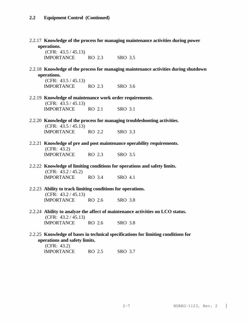
2.2 Equipment Control (Continued)
2.2.17 Knowledge of the process for managing maintenance activities during power operations.
(CFR: 43.5 / 45.13)IMPORTANCE RO 2.3 SRO 3.5
2.2.18 Knowledge of the process for managing maintenance activities during shutdown operations.
(CFR: 43.5 / 45.13)IMPORTANCE RO 2.3 SRO 3.6
2.2.19 Knowledge of maintenance work order requirements. (CFR: 43.5 / 45.13)IMPORTANCE RO 2.1 SRO 3.1
2.2.20 Knowledge of the process for managing troubleshooting activities. (CFR: 43.5 / 45.13)IMPORTANCE RO 2.2 SRO 3.3
2.2.21 Knowledge of pre and post maintenance operability requirements. (CFR: 43.2)IMPORTANCE RO 2.3 SRO 3.5
2.2.22 Knowledge of limiting conditions for operations and safety limits. (CFR: 43.2 / 45.2)IMPORTANCE RO 3.4 SRO 4.1
2.2.23 Ability to track limiting conditions for operations. (CFR: 43.2 / 45.13)IMPORTANCE RO 2.6 SRO 3.8
2.2.24 Ability to analyze the affect of maintenance activities on LCO status. (CFR: 43.2 / 45.13)IMPORTANCE RO 2.6 SRO 3.8
2.2.25 Knowledge of bases in technical specifications for limiting conditions for operations and safety limits.
(CFR: 43.2)IMPORTANCE RO 2.5 SRO 3.7

NUREG-1123, Rev. 2 |2-8
2.2 Equipment Control (Continued)
2.2.26 Knowledge of refueling administrative requirements. (CFR: 43.5 / 45.13)IMPORTANCE RO 2.5 SRO 3.7
2.2.27 Knowledge of the refueling process. (CFR: 43.6 / 45.13)
IMPORTANCE RO 2.6 SRO 3.5
2.2.28 Knowledge of new and spent fuel movement procedures.| (CFR: 43.7 / 45.13)IMPORTANCE RO 2.6 SRO 3.5
2.2.29 Knowledge of SRO fuel handling responsibilities.| (CFR: 43.6 / 45.12)IMPORTANCE RO 1.6 SRO 3.8
2.2.30 Knowledge of RO duties in the control room during fuel handling such as alarms| from fuel handling area / communication with fuel storage facility / systems operated from the control room in support of fueling operations / and supporting instrumentation.
(CFR: 45.12)IMPORTANCE RO 3.5 SRO 3.3
2.2.31 Knowledge of procedures and limitations involved in initial core loading.| (CFR: 43.6)IMPORTANCE RO 2.2 SRO 2.9*
2.2.32 Knowledge of the effects of alterations on core configuration.| (CFR: 43.6)IMPORTANCE RO 2.3 SRO 3.3
2.2.33 Knowledge of control rod programming.| (CFR: 43.6)IMPORTANCE RO 2.5 SRO 2.9
2.2.34 Knowledge of the process for determining the internal and external effects on core|reactivity.
(CFR: 43.6)IMPORTANCE RO 2.8 SRO 3.2*
NUREG-1123, Rev. 2 |2-9
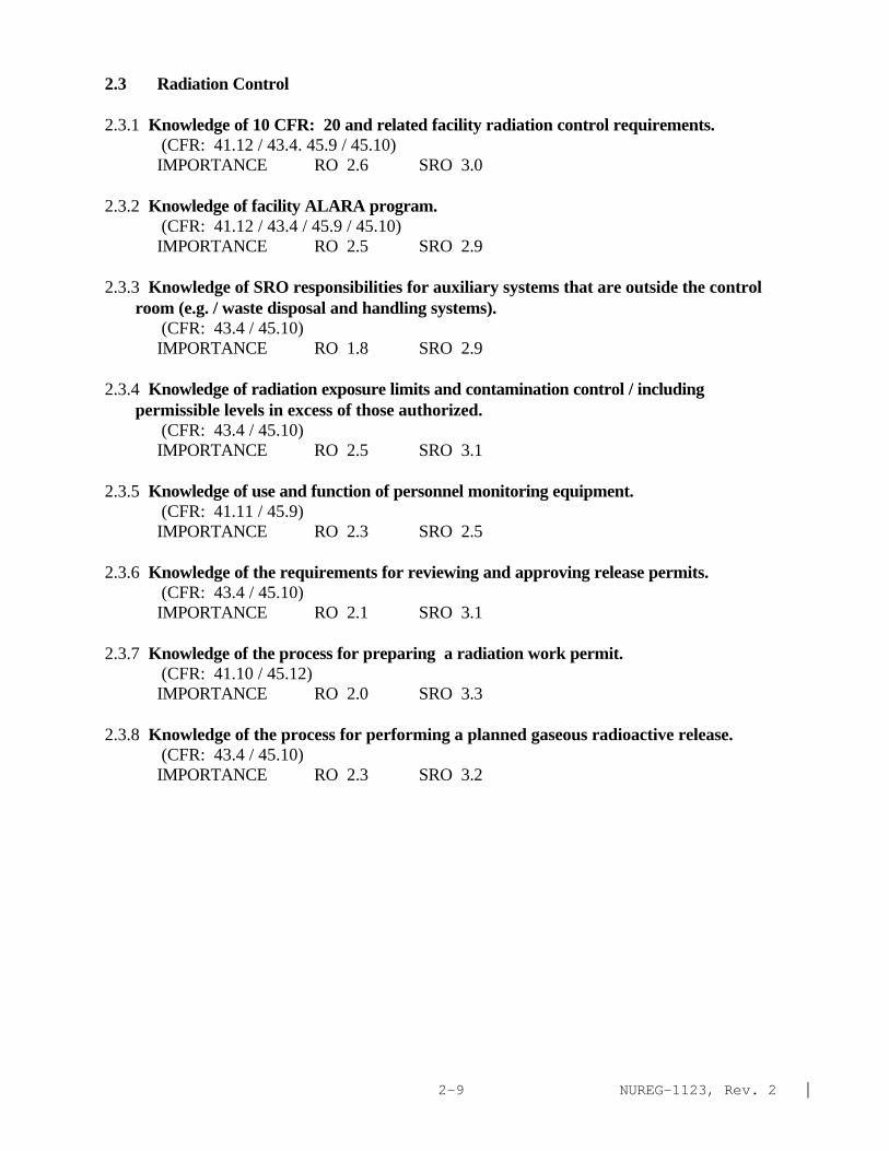
2.3 Radiation Control
2.3.1 Knowledge of 10 CFR: 20 and related facility radiation control requirements. (CFR: 41.12 / 43.4. 45.9 / 45.10)IMPORTANCE RO 2.6 SRO 3.0
2.3.2 Knowledge of facility ALARA program. (CFR: 41.12 / 43.4 / 45.9 / 45.10)IMPORTANCE RO 2.5 SRO 2.9
2.3.3 Knowledge of SRO responsibilities for auxiliary systems that are outside the control room (e.g. / waste disposal and handling systems).
(CFR: 43.4 / 45.10)IMPORTANCE RO 1.8 SRO 2.9
2.3.4 Knowledge of radiation exposure limits and contamination control / including permissible levels in excess of those authorized.
(CFR: 43.4 / 45.10)IMPORTANCE RO 2.5 SRO 3.1
2.3.5 Knowledge of use and function of personnel monitoring equipment. (CFR: 41.11 / 45.9)IMPORTANCE RO 2.3 SRO 2.5
2.3.6 Knowledge of the requirements for reviewing and approving release permits. (CFR: 43.4 / 45.10)IMPORTANCE RO 2.1 SRO 3.1
2.3.7 Knowledge of the process for preparing a radiation work permit. (CFR: 41.10 / 45.12)IMPORTANCE RO 2.0 SRO 3.3
2.3.8 Knowledge of the process for performing a planned gaseous radioactive release. (CFR: 43.4 / 45.10)IMPORTANCE RO 2.3 SRO 3.2

NUREG-1123, Rev. 2 |2-10
2.3 Radiation Control (Continued)
2.3.9 Knowledge of the process for performing a containment purge. (CFR: 43.4 / 45.10)IMPORTANCE RO 2.5 SRO 3.4
2.3.10 Ability to perform procedures to reduce excessive levels of radiation and guard against personnel exposure.
(CFR: 43.4 / 45.10)IMPORTANCE RO 2.9 SRO 3.3
2.3.11 Ability to control radiation releases. (CFR: 45.9 / 45.10)IMPORTANCE RO 2.7 SRO 3.2
2.4 Emergency Procedures /Plan
2.4.1 Knowledge of EOP entry conditions and immediate action steps. (CFR: 41.10 / 43.5 / 45.13)IMPORTANCE RO 4.3 SRO 4.6
2.4.2 Knowledge of system set points / interlocks and automatic actions associated with EOP entry conditions.
(CFR: 41.7 / 45.7 / 45.8)Note: The issue of setpoints and automatic safety features is not specifically covered in the systems sections).IMPORTANCE RO 3.9 SRO 4.1
2.4.3 Ability to identify post-accident instrumentation. (CFR: 41.6 / 45.4)IMPORTANCE RO 3.5 SRO 3.8
2.4.4 Ability to recognize abnormal indications for system operating parameters which are entry-level conditions for emergency and abnormal operating procedures.
(CFR: 41.10 / 43.2 / 45.6)IMPORTANCE RO 4.0 SRO 4.3
2.4.5 Knowledge of the organization of the operating procedures network for normal / abnormal / and emergency evolutions.
(CFR: 41.10 / 43.5 / 45.13)IMPORTANCE RO 2.9 SRO 3.6

NUREG-1123, Rev. 2 |2-11
2.4 Emergency Procedures /Plan (Continued)
2.4.6 Knowledge symptom based EOP mitigation strategies. (CFR: 41.10 / 43.5 / 45.13)IMPORTANCE RO 3.1 SRO 4.0
2.4.7 Knowledge of event based EOP mitigation strategies. (CFR: 41.10 / 43.5 / 45.13)IMPORTANCE RO 3.1 SRO 3.8
2.4.8 Knowledge of how the event-based emergency/abnormal operating procedures are used in conjunction with the symptom-based EOPs.
(CFR: 41.10 / 43.5 / 45.13)IMPORTANCE RO 3.0 SRO 3.7
2.4.9 Knowledge of low power / shutdown implications in accident (e.g. LOCA or loss of RHR) mitigation strategies.
(CFR: 41.10 / 43.5 / 45.13)IMPORTANCE RO 3.3 SRO 3.9
2.4.10 Knowledge of annunciator response procedures. (CFR: 41.10 / 43.5 / 45.13)IMPORTANCE RO 3.0 SRO 3.1
2.4.11 Knowledge of abnormal condition procedures. (CFR: 41.10 / 43.5 / 45.13)IMPORTANCE RO 3.4 SRO 3.6
2.4.12 Knowledge of general operating crew responsibilities during emergency operations.
(CFR: 41.10 / 45.12)IMPORTANCE RO 3.4 SRO 3.9
2.4.13 Knowledge of crew roles and responsibilities during EOP flowchart use. (CFR: 41.10 / 45.12)IMPORTANCE RO 3.3 SRO 3.9
2.4.14 Knowledge of general guidelines for EOP flowchart use. (CFR: 41.10 / 45.13 )IMPORTANCE RO 3.0 SRO 3.9
NUREG-1123, Rev. 2 |2-12
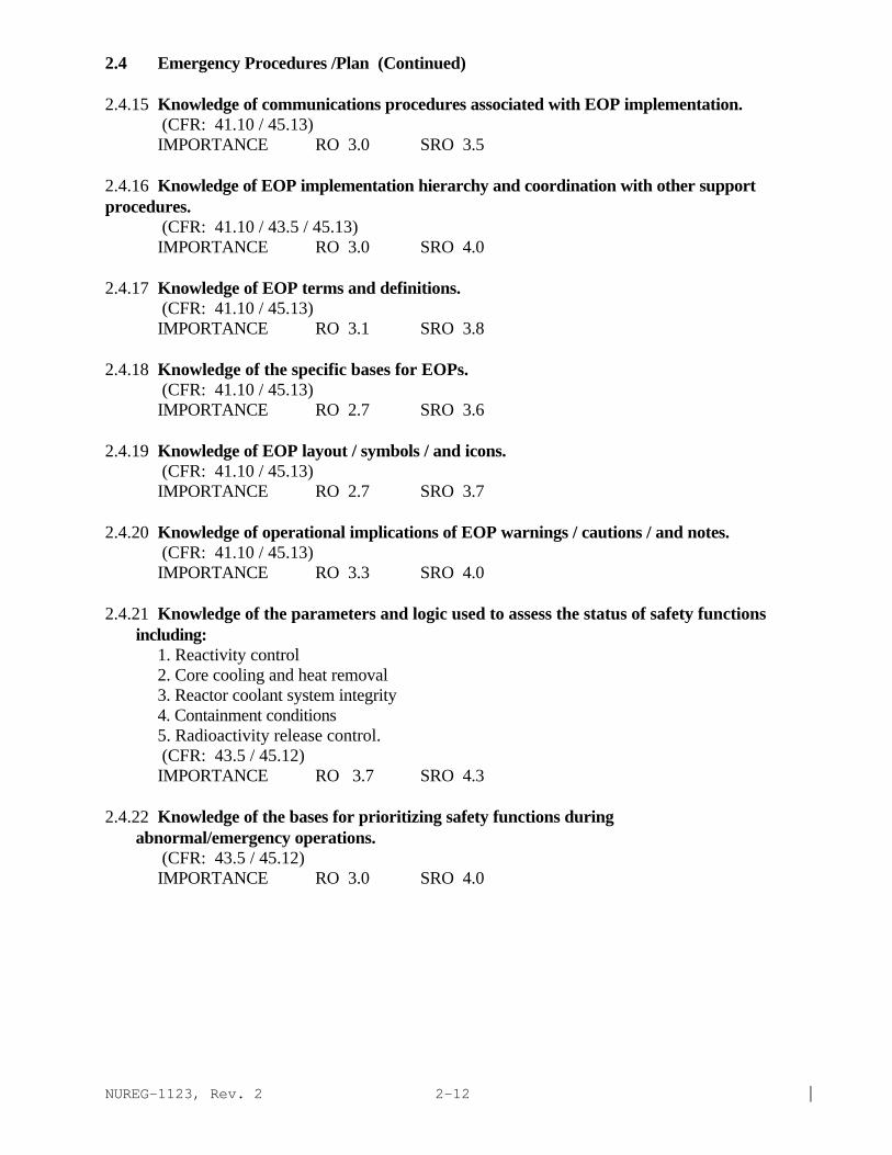
2.4 Emergency Procedures /Plan (Continued)
2.4.15 Knowledge of communications procedures associated with EOP implementation. (CFR: 41.10 / 45.13)IMPORTANCE RO 3.0 SRO 3.5
2.4.16 Knowledge of EOP implementation hierarchy and coordination with other support procedures.
(CFR: 41.10 / 43.5 / 45.13)IMPORTANCE RO 3.0 SRO 4.0
2.4.17 Knowledge of EOP terms and definitions. (CFR: 41.10 / 45.13)IMPORTANCE RO 3.1 SRO 3.8
2.4.18 Knowledge of the specific bases for EOPs. (CFR: 41.10 / 45.13)IMPORTANCE RO 2.7 SRO 3.6
2.4.19 Knowledge of EOP layout / symbols / and icons. (CFR: 41.10 / 45.13)IMPORTANCE RO 2.7 SRO 3.7
2.4.20 Knowledge of operational implications of EOP warnings / cautions / and notes. (CFR: 41.10 / 45.13)IMPORTANCE RO 3.3 SRO 4.0
2.4.21 Knowledge of the parameters and logic used to assess the status of safety functions including:
1. Reactivity control2. Core cooling and heat removal3. Reactor coolant system integrity4. Containment conditions5. Radioactivity release control.
(CFR: 43.5 / 45.12)IMPORTANCE RO 3.7 SRO 4.3
2.4.22 Knowledge of the bases for prioritizing safety functions during abnormal/emergency operations.
(CFR: 43.5 / 45.12)IMPORTANCE RO 3.0 SRO 4.0

NUREG-1123, Rev. 2 |2-13
2.4 Emergency Procedures /Plan (Continued)
2.4.23 Knowledge of the bases for prioritizing emergency procedure implementation during emergency operations.
(CFR: 41.10 / 45.13)IMPORTANCE RO 2.8 SRO 3.8
2.4.24 Knowledge of loss of cooling water procedures. (CFR: 41.10 / 45.13)
IMPORTANCE RO 3.3 SRO 3.7
2.4.25 Knowledge of fire protection procedures. (CFR: 41.10 / 45.13)IMPORTANCE RO 2.9 SRO 3.4
2.4.26 Knowledge of facility protection requirements including fire brigade and portable fire fighting equipment usage.
(CFR: 43.5 / 45.12)IMPORTANCE RO 2.9 SRO 3.3
2.4.27 Knowledge of fire in the plant procedure. (CFR: 41.10 / 43.5 / 45.13)IMPORTANCE RO 3.0 SRO 3.5
2.4.28 Knowledge of procedures relating to emergency response to sabotage. (CFR: 41.10 / 43.5 / 45.13)IMPORTANCE RO 2.3 SRO 3.3
2.4.29 Knowledge of the emergency plan. (CFR: 43.5 / 45.11)IMPORTANCE RO 2.6 SRO 4.0
2.4.30 Knowledge of which events related to system operations/status should be reported to outside agencies.
(CFR: 43.5 / 45.11)IMPORTANCE RO 2.2 SRO 3.6
2.4.31 Knowledge of annunciators alarms and indications / and use of the response instructions.
(CFR: 41.10 / 45.3)IMPORTANCE RO 3.3 SRO 3.4
NUREG-1123, Rev. 2 |2-14
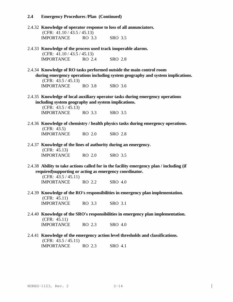
2.4 Emergency Procedures /Plan (Continued)
2.4.32 Knowledge of operator response to loss of all annunciators. (CFR: 41.10 / 43.5 / 45.13)IMPORTANCE RO 3.3 SRO 3.5
2.4.33 Knowledge of the process used track inoperable alarms. (CFR: 41.10 / 43.5 / 45.13)IMPORTANCE RO 2.4 SRO 2.8
2.4.34 Knowledge of RO tasks performed outside the main control room during emergency operations including system geography and system implications.
(CFR: 43.5 / 45.13)IMPORTANCE RO 3.8 SRO 3.6
2.4.35 Knowledge of local auxiliary operator tasks during emergency operations including system geography and system implications.
(CFR: 43.5 / 45.13)IMPORTANCE RO 3.3 SRO 3.5
2.4.36 Knowledge of chemistry / health physics tasks during emergency operations. (CFR: 43.5)IMPORTANCE RO 2.0 SRO 2.8
2.4.37 Knowledge of the lines of authority during an emergency. (CFR: 45.13)
IMPORTANCE RO 2.0 SRO 3.5
2.4.38 Ability to take actions called for in the facility emergency plan / including (if required)supporting or acting as emergency coordinator.
(CFR: 43.5 / 45.11)IMPORTANCE RO 2.2 SRO 4.0
2.4.39 Knowledge of the RO's responsibilities in emergency plan implementation. (CFR: 45.11)IMPORTANCE RO 3.3 SRO 3.1
2.4.40 Knowledge of the SRO's responsibilities in emergency plan implementation. (CFR: 45.11)IMPORTANCE RO 2.3 SRO 4.0
2.4.41 Knowledge of the emergency action level thresholds and classifications. (CFR: 43.5 / 45.11)IMPORTANCE RO 2.3 SRO 4.1

NUREG-1123, Rev. 2 |2-15
2.4 Emergency Procedures /Plan (Continued)
2.4.42 Knowledge of emergency response facilities. (CFR: 45.11)IMPORTANCE RO 2.3 SRO 3.7
2.4.43 Knowledge of emergency communications systems and techniques. (CFR: 45.13)IMPORTANCE RO 2.8 SRO 3.5
2.4.44 Knowledge of emergency plan protective action recommendations. (CFR: 43.5 / 45.11)IMPORTANCE RO 2.1 SRO 4.0
2.4.45 Ability to prioritize and interpret the significance of each annunciator or alarm. (CFR: 43.5 / 45.3 / 45.12)IMPORTANCE RO 3.3 SRO 3.6
2.4.46 Ability to verify that the alarms are consistent with the plant conditions. (CFR: 43.5 / 45.3 / 45.12)IMPORTANCE RO 3.5 SRO 3.6
2.4.47 Ability to diagnose and recognize trends in an accurate and timely manner utilizing the appropriate control room reference material.
(CFR: : 41.10 /43.5 / 45.12)IMPORTANCE RO 3.4 SRO 3.7
2.4.48 Ability to interpret control room indications to verify the status and operation of system / and understand how operator action s and directives affect plant and system conditions.
(CFR: 43.5 / 45.12)IMPORTANCE RO 3.5 SRO 3.8
2.4.49 Ability to perform without reference to procedures those actions that require immediate operation of system components and controls.
(CFR: 41.10 / 43.2 / 45.6)IMPORTANCE RO 4.0 SRO 4.0
2.4.50 Ability to verify system alarm setpoints and operate controls identified in the alarm response manual.
(CFR: 45.3)IMPORTANCE RO 3.3 SRO 3.3

NUREG-1123, Rev. 2 |2-16
This page left blank

NUREG-1123, Rev. 2 |3.1-1
3.1 Reactivity Control page
201001 Control Rod Drive Hydraulic System 3.1-3201003 Control Rod and Drive Mechanism 3.1-7201002 Reactor Manual Control System 3.1-10202002 Recirculation flow Control System 3.1-13202001 Recirculation System 3.1-17201005 Rod Control and Information System 3.1-22211000 Standby Liquid Control System 3.1-25

NUREG-1123, Rev. 2 |3.1-2
This page left blank

NUREG-1123, Rev. 2 |3.1-3
SYSTEM: 201001 Control Rod Drive Hydraulic System
TASK: Perform lineups on the CRD hydraulic systemPlace the control rod drive system in serviceMonitor the control rod Drive SystemRemove Control Rod Drive System From ServiceVent the control rod drive system (write in)Conduct CRD hydraulics valve testing during cold shutdown
IMPORTANCE K/A NO. KNOWLEDGE RO SRO
K1. Knowledge of the physical connections and/or cause-effect relationships between CONTROL ROD DRIVEHYDRAULIC SYSTEM and the following:(CFR: 41.2 to 41.9 / 45.7 to 45.8)
K1.01 Condensate system . . . . . . . . . . . . . . . . . . . . . . . . . . . . . . . . . . . . . . . . . . . . . . . . . . . . . . 3.1 3.1K1.02 Condensate storage tanks . . . . . . . . . . . . . . . . . . . . . . . . . . . . . . . . . . . . . . . . . . . . . . . . . 3.0 3.0K1.03 Recirculation pumps (seal purge): Plant-Specific . . . . . . . . . . . . . . . . . . . . . . . . . . . . 3.1 3.1K1.04 Head spray: BWR-3 . . . . . . . . . . . . . . . . . . . . . . . . . . . . . . . . . . . . . . . . . . . . . . . . . . . . 2.7 2.7K1.05 Feedwater (or reactor water cleanup)-CRD return to
vessel: Plant-Specific . . . . . . . . . . . . . . . . . . . . . . . . . . . . . . . . . . . . . . . . . . . . . . . . . . . 2.7 2.7K1.06 Component cooling water systems: Plant-Specific . . . . . . . . . . . . . . . . . . . . . . . . . . . 2.8 2.8K1.07 Reactor protection system . . . . . . . . . . . . . . . . . . . . . . . . . . . . . . . . . . . . . . . . . . . . . . . 3.4 3.4K1.08 Reactor manual control system . . . . . . . . . . . . . . . . . . . . . . . . . . . . . . . . . . . . . . . . . . . . 3.4 3.4K1.09 Plant air systems . . . . . . . . . . . . . . . . . . . . . . . . . . . . . . . . . . . . . . . . . . . . . . . . . . . . . . . 3.1 3.2K1.10 Control rod drive mechanisms . . . . . . . . . . . . . . . . . . . . . . . . . . . . . . . . . . . . . . . . . . . . 2.8 2.8K1.11 Reactor water cleanup pumps: Plant-Specific . . . . . . . . . . . . . . . . . . . . . . . . . . . . . . . 2.8 2.8
K2. Knowledge of electrical power supplies to thefollowing:(CFR: 41.7)
K2.01 Pumps . . . . . . . . . . . . . . . . . . . . . . . . . . . . . . . . . . . . . . . . . . . . . . . . . . . . . . . . . . . . . . . . 2.9 3.1K2.02 Scram valve solenoids . . . . . . . . . . . . . . . . . . . . . . . . . . . . . . . . . . . . . . . . . . . . . . . . . . . 3.6* 3.7K2.03 Backup SCRAM valve solenoids . . . . . . . . . . . . . . . . . . . . . . . . . . . . . . . . . . . . . . . . . . . 3.5* 3.6*K2.04 Scram discharge volume vent and drain valve solenoids. . . . . . . . . . . . . . . . . . . . . . . . 3.2 3.3K2.05 Alternate rod insertion valve solenoids: Plant-Specific . . . . . . . . . . . . . . . . . . . . . . . 4.5* 4.5*K2.06 Motor operated valves . . . . . . . . . . . . . . . . . . . . . . . . . . . . . . . . . . . . . . . . . . . . . . . . . . . 2.1* 2.3*K2.07 Breaker control . . . . . . . . . . . . . . . . . . . . . . . . . . . . . . . . . . . . . . . . . . . . . . . . . . . . . . . . . 2.0* 2.1*
K3. Knowledge of the effect that a loss or malfunction ofthe CONTROL ROD DRIVE HYDRAULIC SYSTEM will have onfollowing:(CFR: 41.7 / 45.4)
K3.01 Recirculation pumps: Plant-Specific . . . . . . . . . . . . . . . . . . . . . . . . . . . . . . . . . . . . . . . 3.0 3.1K3.02 Reactor water level . . . . . . . . . . . . . . . . . . . . . . . . . . . . . . . . . . . . . . . . . . . . . . . . . . . . . 2.6 2.6K3.03 Control rod drive mechanisms . . . . . . . . . . . . . . . . . . . . . . . . . . . . . . . . . . . . . . . . . . . . 3.1 3.2K3.04 Head spray: BWR-3 . . . . . . . . . . . . . . . . . . . . . . . . . . . . . . . . . . . . . . . . . . . . . . . . . . . . 2.7 2.7K3.05 Reactor water cleanup pumps: Plant-Specific . . . . . . . . . . . . . . . . . . . . . . . . . . . . . . . 2.3 2.3

NUREG-1123, Rev. 2 |3.1-4
SYSTEM: 201001 Control Rod Drive Hydraulic System
Tasks as noted previouslyIMPORTANCE
K/A NO. KNOWLEDGE RO SRO
K4. Knowledge of CONTROL ROD DRIVE HYDRAULIC SYSTEM designfeature(s) and/or interlocks which provide for thefollowing:(CFR 41.7)
K4.01 Protection against pump runout during SCRAM conditions(location of the CRD system flow element and arestricting orifice in the accumulator charging water line) . . . . . . . . . . . . . . . . . . . . . 2.5 2.6
K4.02 Stable system flow when moving control rods(stabilizing valves) . . . . . . . . . . . . . . . . . . . . . . . . . . . . . . . . . . . . . . . . . . . . . . . . . . . . . . 2.6 2.6
K4.03 Control rod drive mechanism cooling water flow . . . . . . . . . . . . . . . . . . . . . . . . . . . . . 2.7 2.7K4.04 Scramming control rods with inoperative SCRAM solenoid
valves (back-up SCRAM valves) . . . . . . . . . . . . . . . . . . . . . . . . . . . . . . . . . . . . . . . . . . . 3.6 3.6K4.05 Control rod SCRAM . . . . . . . . . . . . . . . . . . . . . . . . . . . . . . . . . . . . . . . . . . . . . . . . . . . . 3.8 3.8K4.06 Isolation of the SCRAM discharge volumes during SCRAM|
conditions . . . . . . . . . . . . . . . . . . . . . . . . . . . . . . . . . . . . . . . . . . . . . . . . . . . . . . . . . . . . . 3.8 3.9K4.07 Testing SCRAM discharge volume isolation valves . . . . . . . . . . . . . . . . . . . . . . . . . . . 2.8 2.8K4.08 Controlling control rod drive header pressure . . . . . . . . . . . . . . . . . . . . . . . . . . . . . . . 3.1 3.0K4.09 Controlling control rod drive cooling header pressure . . . . . . . . . . . . . . . . . . . . . . . . 2.9 2.8 K4.10 Control of rod movement (HCU directional control valves) . . . . . . . . . . . . . . . . . . . . 3.1 3.0K4.11 Protection against filling the SDV during non-SCRAM conditions . . . . . . . . . . . . . . 3.6 3.6K4.12 Controlling CRD system flow . . . . . . . . . . . . . . . . . . . . . . . . . . . . . . . . . . . . . . . . . . . . . 2.9 2.9K4.13 Motor cooling . . . . . . . . . . . . . . . . . . . . . . . . . . . . . . . . . . . . . . . . . . . . . . . . . . . . . . . . . . 2.3 2.3
K5. Knowledge of the operational implications of thefollowing concepts as they apply to CONTROL ROD DRIVEHYDRAULIC SYSTEM :(CFR: : : 41.5 / 45.3)
K5.01 Pump operation . . . . . . . . . . . . . . . . . . . . . . . . . . . . . . . . . . . . . . . . . . . . . . . . . . . . . . . . . 2.4 2.4K5.02 Flow indication . . . . . . . . . . . . . . . . . . . . . . . . . . . . . . . . . . . . . . . . . . . . . . . . . . . . . . . . . 2.6 2.6K5.03 Pressure indication . . . . . . . . . . . . . . . . . . . . . . . . . . . . . . . . . . . . . . . . . . . . . . . . . . . . . . 2.7 2.7K5.04 Indications of pump cavitation . . . . . . . . . . . . . . . . . . . . . . . . . . . . . . . . . . . . . . . . . . . . 2.4 2.4K5.05 Indications of pump runout: Plant-Specific . . . . . . . . . . . . . . . . . . . . . . . . . . . . . . . . . 2.7 2.7K5.06 Differential pressure indication . . . . . . . . . . . . . . . . . . . . . . . . . . . . . . . . . . . . . . . . . . . 2.5 2.6K5.07 Air operated control valves . . . . . . . . . . . . . . . . . . . . . . . . . . . . . . . . . . . . . . . . . . . . . . . 2.3 2.4K5.08 Solenoid operated valves . . . . . . . . . . . . . . . . . . . . . . . . . . . . . . . . . . . . . . . . . . . . . . . . . 2.5 2.6K5.09 System venting . . . . . . . . . . . . . . . . . . . . . . . . . . . . . . . . . . . . . . . . . . . . . . . . . . . . . . . . . 2.2* 2.2*
K6. Knowledge of the effect that a loss or malfunction ofthe following will have on the CONTROL ROD DRIVEHYDRAULIC System :(CFR: 41.7 / 45.7)
K6.01 Condensate system . . . . . . . . . . . . . . . . . . . . . . . . . . . . . . . . . . . . . . . . . . . . . . . . . . . . . . 2.8 2.8K6.02 Condensate storage tanks . . . . . . . . . . . . . . . . . . . . . . . . . . . . . . . . . . . . . . . . . . . . . . . . . 3.0 3.1

NUREG-1123, Rev. 2 |3.1-5
SYSTEM: 201001 Control Rod Drive Hydraulic System
Tasks as noted previouslyIMPORTANCE
K/A NO. KNOWLEDGE RO SRO
K6.03 Plant air systems . . . . . . . . . . . . . . . . . . . . . . . . . . . . . . . . . . . . . . . . . . . . . . . . . . . . . . . . 3.0 2.9K6.04 RPS . . . . . . . . . . . . . . . . . . . . . . . . . . . . . . . . . . . . . . . . . . . . . . . . . . . . . . . . . . . . . . . . . . 3.6 3.7 |K6.05 A.C. power . . . . . . . . . . . . . . . . . . . . . . . . . . . . . . . . . . . . . . . . . . . . . . . . . . . . . . . . . . . . . 3.3 3.3K6.06 Component cooling water systems: Plant-Specific . . . . . . . . . . . . . . . . . . . . . . . . . . . 2.8 2.8
ABILITY
A1. Ability to predict and/or monitor changes inparameters associated with operating the CONTROL RODDRIVE HYDRAULIC SYSTEM controls including:(CFR: 41.5 / 45.5)
A1.01 CRD drive water header pressure . . . . . . . . . . . . . . . . . . . . . . . . . . . . . . . . . . . . . . . . . . 3.1 2.9A1.02 CRD cooling water header pressure . . . . . . . . . . . . . . . . . . . . . . . . . . . . . . . . . . . . . . . . 2.9 2.9A1.03 CRD system flow . . . . . . . . . . . . . . . . . . . . . . . . . . . . . . . . . . . . . . . . . . . . . . . . . . . . . . . 2.9 2.8A1.04 Head spray flow: BWR-3 . . . . . . . . . . . . . . . . . . . . . . . . . . . . . . . . . . . . . . . . . . . . . . . . 2.7 2.7A1.05 SDV isolation valve position . . . . . . . . . . . . . . . . . . . . . . . . . . . . . . . . . . . . . . . . . . . . . . 3.5 3.4A1.06 HCU pressure/level . . . . . . . . . . . . . . . . . . . . . . . . . . . . . . . . . . . . . . . . . . . . . . . . . . . . . 3.4 3.4A1.07 Reactor water level . . . . . . . . . . . . . . . . . . . . . . . . . . . . . . . . . . . . . . . . . . . . . . . . . . . . . . 3.3 3.2A1.08 Pump amps . . . . . . . . . . . . . . . . . . . . . . . . . . . . . . . . . . . . . . . . . . . . . . . . . . . . . . . . . . . . 2.3 2.2A1.09 CRD drive water flow. . . . . . . . . . . . . . . . . . . . . . . . . . . . . . . . . . . . . . . . . . . . . . . . . . . . 2.9 2.8A1.10 CRD cooling water flow . . . . . . . . . . . . . . . . . . . . . . . . . . . . . . . . . . . . . . . . . . . . . . . . . 2.8 2.6
A2. Ability to (a) predict the impacts of the following onthe CONTROL ROD DRIVE HYDRAULIC SYSTEM ; and (b) basedon those predictions, use procedures to correct,control, or mitigate the consequences of thoseabnormal conditions or operations:(CFR: 41.5 / 45.6)
A2.01 Pumps trips . . . . . . . . . . . . . . . . . . . . . . . . . . . . . . . . . . . . . . . . . . . . . . . . . . . . . . . . . . . . 3.2 3.3A2.02 Valve closures . . . . . . . . . . . . . . . . . . . . . . . . . . . . . . . . . . . . . . . . . . . . . . . . . . . . . . . . . . 3.2 3.3A2.03 Power supply failures . . . . . . . . . . . . . . . . . . . . . . . . . . . . . . . . . . . . . . . . . . . . . . . . . . . . 3.0 3.1A2.04 †Scram conditions . . . . . . . . . . . . . . . . . . . . . . . . . . . . . . . . . . . . . . . . . . . . . . . . . . . . . . 3.8 3.9*A2.05 Discharge strainer(s) becoming plugged . . . . . . . . . . . . . . . . . . . . . . . . . . . . . . . . . . . . 2.9 2.9A2 06 Suction strainer(s) becoming plugged . . . . . . . . . . . . . . . . . . . . . . . . . . . . . . . . . . . . . . 2.9 2.9A2.07 Flow control valve failure . . . . . . . . . . . . . . . . . . . . . . . . . . . . . . . . . . . . . . . . . . . . . . . . 3.2 3.1A2.08 Inadequate system flow . . . . . . . . . . . . . . . . . . . . . . . . . . . . . . . . . . . . . . . . . . . . . . . . . . 2.8 2.8A2.09 Loss of applicable plant air systems . . . . . . . . . . . . . . . . . . . . . . . . . . . . . . . . . . . . . . . . 3.2 3.1A2.10 †Low HCU accumulator pressure/high level . . . . . . . . . . . . . . . . . . . . . . . . . . . . . . . . . 3.5 3.6A2 11 Valve openings . . . . . . . . . . . . . . . . . . . . . . . . . . . . . . . . . . . . . . . . . . . . . . . . . . . . . . . . . 2.6 2.7A2.12 High cooling water flow . . . . . . . . . . . . . . . . . . . . . . . . . . . . . . . . . . . . . . . . . . . . . . . . . 2.8 2.9A2.13 Low cooling water flow . . . . . . . . . . . . . . . . . . . . . . . . . . . . . . . . . . . . . . . . . . . . . . . . . . 2.7 2.8A2.14 Low drive header pressure . . . . . . . . . . . . . . . . . . . . . . . . . . . . . . . . . . . . . . . . . . . . . . . . 2.8 2.8
NUREG-1123, Rev. 2 |3.1-6
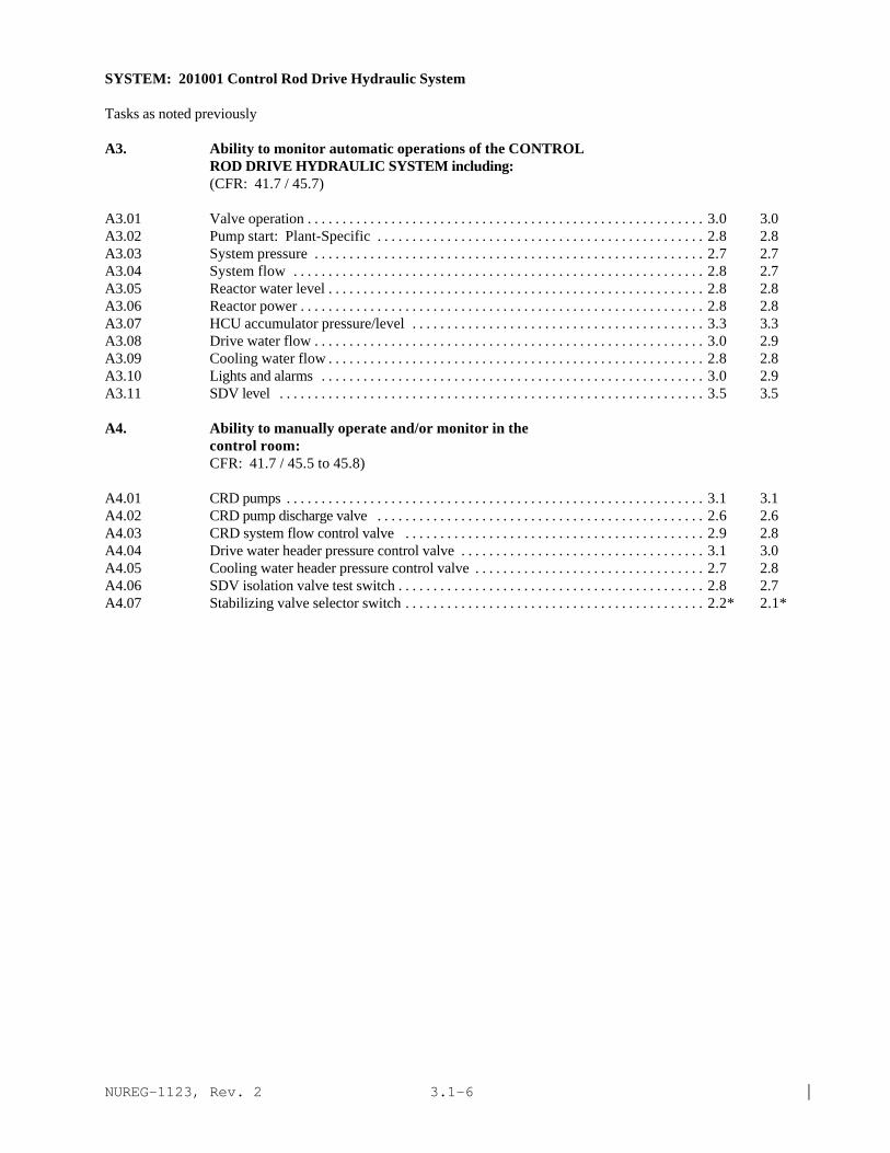
SYSTEM: 201001 Control Rod Drive Hydraulic System
Tasks as noted previously
A3. Ability to monitor automatic operations of the CONTROLROD DRIVE HYDRAULIC SYSTEM including:(CFR: 41.7 / 45.7)
A3.01 Valve operation . . . . . . . . . . . . . . . . . . . . . . . . . . . . . . . . . . . . . . . . . . . . . . . . . . . . . . . . . 3.0 3.0A3.02 Pump start: Plant-Specific . . . . . . . . . . . . . . . . . . . . . . . . . . . . . . . . . . . . . . . . . . . . . . . 2.8 2.8A3.03 System pressure . . . . . . . . . . . . . . . . . . . . . . . . . . . . . . . . . . . . . . . . . . . . . . . . . . . . . . . . 2.7 2.7A3.04 System flow . . . . . . . . . . . . . . . . . . . . . . . . . . . . . . . . . . . . . . . . . . . . . . . . . . . . . . . . . . . 2.8 2.7A3.05 Reactor water level . . . . . . . . . . . . . . . . . . . . . . . . . . . . . . . . . . . . . . . . . . . . . . . . . . . . . . 2.8 2.8A3.06 Reactor power . . . . . . . . . . . . . . . . . . . . . . . . . . . . . . . . . . . . . . . . . . . . . . . . . . . . . . . . . . 2.8 2.8A3.07 HCU accumulator pressure/level . . . . . . . . . . . . . . . . . . . . . . . . . . . . . . . . . . . . . . . . . . 3.3 3.3A3.08 Drive water flow . . . . . . . . . . . . . . . . . . . . . . . . . . . . . . . . . . . . . . . . . . . . . . . . . . . . . . . . 3.0 2.9A3.09 Cooling water flow . . . . . . . . . . . . . . . . . . . . . . . . . . . . . . . . . . . . . . . . . . . . . . . . . . . . . . 2.8 2.8A3.10 Lights and alarms . . . . . . . . . . . . . . . . . . . . . . . . . . . . . . . . . . . . . . . . . . . . . . . . . . . . . . . 3.0 2.9A3.11 SDV level . . . . . . . . . . . . . . . . . . . . . . . . . . . . . . . . . . . . . . . . . . . . . . . . . . . . . . . . . . . . . 3.5 3.5
A4. Ability to manually operate and/or monitor in thecontrol room:CFR: 41.7 / 45.5 to 45.8)
A4.01 CRD pumps . . . . . . . . . . . . . . . . . . . . . . . . . . . . . . . . . . . . . . . . . . . . . . . . . . . . . . . . . . . . 3.1 3.1A4.02 CRD pump discharge valve . . . . . . . . . . . . . . . . . . . . . . . . . . . . . . . . . . . . . . . . . . . . . . . 2.6 2.6A4.03 CRD system flow control valve . . . . . . . . . . . . . . . . . . . . . . . . . . . . . . . . . . . . . . . . . . . 2.9 2.8A4.04 Drive water header pressure control valve . . . . . . . . . . . . . . . . . . . . . . . . . . . . . . . . . . . 3.1 3.0A4.05 Cooling water header pressure control valve . . . . . . . . . . . . . . . . . . . . . . . . . . . . . . . . . 2.7 2.8A4.06 SDV isolation valve test switch . . . . . . . . . . . . . . . . . . . . . . . . . . . . . . . . . . . . . . . . . . . . 2.8 2.7A4.07 Stabilizing valve selector switch . . . . . . . . . . . . . . . . . . . . . . . . . . . . . . . . . . . . . . . . . . . 2.2* 2.1*

NUREG-1123, Rev. 2 |3.1-7
SYSTEM: 201003 Control Rod and Drive Mechanism
TASK: Flush a CRD mechanismConduct Control Rod Operability TestConduct Control Rod Coupling Integrity TestPerform Control Rod Drive Stall Flow Testing (CRD 18-Month Accumulator Operability Test)Perform control rod drive accumulator piston seal exercisingPerform the control rod drive timing test (write in)Perform friction testing
IMPORTANCE K/A NO. KNOWLEDGE RO SRO
K1. Knowledge of the physical connections and/or cause-effect relationships between CONTROL ROD AND DRIVEMECHANISM and the following:(CFR: 41.2 to 41.9 / 45.7 to 45.8)
K1.01 Control rod drive hydraulic system . . . . . . . . . . . . . . . . . . . . . . . . . . . . . . . . . . . . . . . . 3.2 3.3K1.02 Reactor water . . . . . . . . . . . . . . . . . . . . . . . . . . . . . . . . . . . . . . . . . . . . . . . . . . . . . . . . . . 2.9 3.0K1.03 RPIS . . . . . . . . . . . . . . . . . . . . . . . . . . . . . . . . . . . . . . . . . . . . . . . . . . . . . . . . . . . . . . . . . 3.1 3.1K1.04 Reactor vessel . . . . . . . . . . . . . . . . . . . . . . . . . . . . . . . . . . . . . . . . . . . . . . . . . . . . . . . . . 2.9 2.9K1.05 CRD mechanism temperature monitor . . . . . . . . . . . . . . . . . . . . . . . . . . . . . . . . . . . . . 2.6 2.6
K2. Knowledge of electrical power supplies to thefollowing: (CFR: 41.7)
None |
K3. Knowledge of the effect that a loss or malfunction ofthe CONTROL ROD AND DRIVE MECHANISM will have onfollowing:(CFR: 41.7 / 45.4)
K3.01 Reactor power . . . . . . . . . . . . . . . . . . . . . . . . . . . . . . . . . . . . . . . . . . . . . . . . . . . . . . . . . 3.2 3.4K3.02 †Flux shaping . . . . . . . . . . . . . . . . . . . . . . . . . . . . . . . . . . . . . . . . . . . . . . . . . . . . . . . . . . 2.8 3.1K3.03 †Shutdown margin . . . . . . . . . . . . . . . . . . . . . . . . . . . . . . . . . . . . . . . . . . . . . . . . . . . . . . 3.2 3.8
K4. Knowledge of CONTROL ROD AND DRIVE MECHANISM designfeature(s) and/or interlocks which provide for thefollowing: (CFR: 41.7)
K4.01 Limiting control rod speed in the event of a rod drop . . . . . . . . . . . . . . . . . . . . . . . . . 2.9* 3.0*K4.02 Detection of an uncoupled rod . . . . . . . . . . . . . . . . . . . . . . . . . . . . . . . . . . . . . . . . . . . . 3.8 3.9K4.03 Slowing the drive mechanism near the end of its travel
following a SCRAM: Plant-Specific . . . . . . . . . . . . . . . . . . . . . . . . . . . . . . . . . . . . . . 2.1* 2.1*K4.04 The use of either accumulator or reactor water to
SCRAM the control rod . . . . . . . . . . . . . . . . . . . . . . . . . . . . . . . . . . . . . . . . . . . . . . . . . 3.6 3.7K4.05 Rod position indication . . . . . . . . . . . . . . . . . . . . . . . . . . . . . . . . . . . . . . . . . . . . . . . . . . 3.2 3.3K4.06 Uncoupling the control rod from the drive mechanism . . . . . . . . . . . . . . . . . . . . . . . . 2.4 2.6K4.07 Maintaining the control rod at a given location . . . . . . . . . . . . . . . . . . . . . . . . . . . . . . 3.2 3.2K4.08 Monitoring CRD mechanism temperature . . . . . . . . . . . . . . . . . . . . . . . . . . . . . . . . . . 2.6 2.7
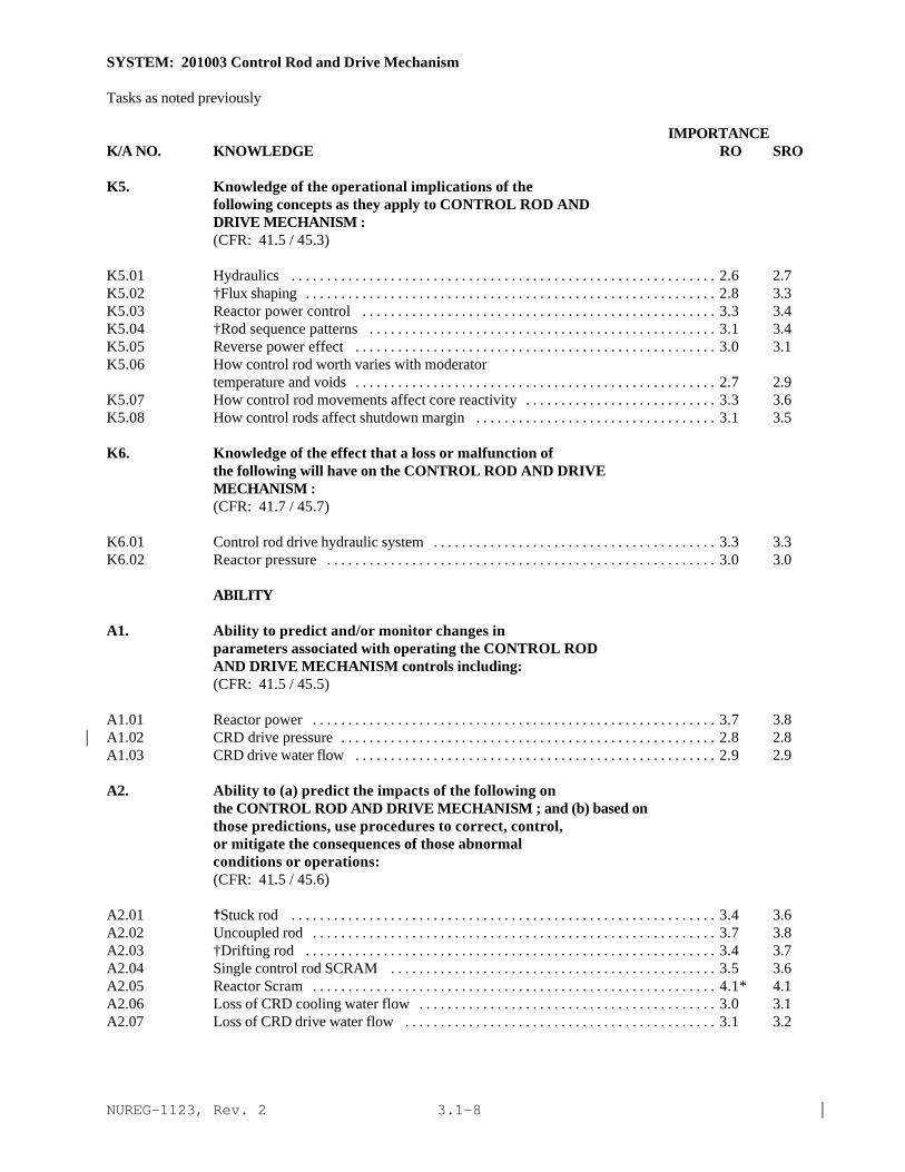
NUREG-1123, Rev. 2 |3.1-8
SYSTEM: 201003 Control Rod and Drive Mechanism
Tasks as noted previously
IMPORTANCE K/A NO. KNOWLEDGE RO SRO
K5. Knowledge of the operational implications of thefollowing concepts as they apply to CONTROL ROD ANDDRIVE MECHANISM :(CFR: 41.5 / 45.3)
K5.01 Hydraulics . . . . . . . . . . . . . . . . . . . . . . . . . . . . . . . . . . . . . . . . . . . . . . . . . . . . . . . . . . . . 2.6 2.7K5.02 †Flux shaping . . . . . . . . . . . . . . . . . . . . . . . . . . . . . . . . . . . . . . . . . . . . . . . . . . . . . . . . . . 2.8 3.3K5.03 Reactor power control . . . . . . . . . . . . . . . . . . . . . . . . . . . . . . . . . . . . . . . . . . . . . . . . . . 3.3 3.4K5.04 †Rod sequence patterns . . . . . . . . . . . . . . . . . . . . . . . . . . . . . . . . . . . . . . . . . . . . . . . . . 3.1 3.4K5.05 Reverse power effect . . . . . . . . . . . . . . . . . . . . . . . . . . . . . . . . . . . . . . . . . . . . . . . . . . . 3.0 3.1K5.06 How control rod worth varies with moderator
temperature and voids . . . . . . . . . . . . . . . . . . . . . . . . . . . . . . . . . . . . . . . . . . . . . . . . . . . 2.7 2.9K5.07 How control rod movements affect core reactivity . . . . . . . . . . . . . . . . . . . . . . . . . . . 3.3 3.6K5.08 How control rods affect shutdown margin . . . . . . . . . . . . . . . . . . . . . . . . . . . . . . . . . . 3.1 3.5
K6. Knowledge of the effect that a loss or malfunction ofthe following will have on the CONTROL ROD AND DRIVEMECHANISM :(CFR: 41.7 / 45.7)
K6.01 Control rod drive hydraulic system . . . . . . . . . . . . . . . . . . . . . . . . . . . . . . . . . . . . . . . . 3.3 3.3K6.02 Reactor pressure . . . . . . . . . . . . . . . . . . . . . . . . . . . . . . . . . . . . . . . . . . . . . . . . . . . . . . . 3.0 3.0
ABILITY
A1. Ability to predict and/or monitor changes inparameters associated with operating the CONTROL RODAND DRIVE MECHANISM controls including:(CFR: 41.5 / 45.5)
A1.01 Reactor power . . . . . . . . . . . . . . . . . . . . . . . . . . . . . . . . . . . . . . . . . . . . . . . . . . . . . . . . . 3.7 3.8A1.02 CRD drive pressure . . . . . . . . . . . . . . . . . . . . . . . . . . . . . . . . . . . . . . . . . . . . . . . . . . . . . 2.8 2.8|A1.03 CRD drive water flow . . . . . . . . . . . . . . . . . . . . . . . . . . . . . . . . . . . . . . . . . . . . . . . . . . . 2.9 2.9
A2. Ability to (a) predict the impacts of the following onthe CONTROL ROD AND DRIVE MECHANISM ; and (b) based onthose predictions, use procedures to correct, control,or mitigate the consequences of those abnormalconditions or operations:(CFR: 41.5 / 45.6)
A2.01 ^Stuck rod . . . . . . . . . . . . . . . . . . . . . . . . . . . . . . . . . . . . . . . . . . . . . . . . . . . . . . . . . . . . 3.4 3.6A2.02 Uncoupled rod . . . . . . . . . . . . . . . . . . . . . . . . . . . . . . . . . . . . . . . . . . . . . . . . . . . . . . . . . 3.7 3.8A2.03 †Drifting rod . . . . . . . . . . . . . . . . . . . . . . . . . . . . . . . . . . . . . . . . . . . . . . . . . . . . . . . . . . 3.4 3.7A2.04 Single control rod SCRAM . . . . . . . . . . . . . . . . . . . . . . . . . . . . . . . . . . . . . . . . . . . . . . 3.5 3.6A2.05 Reactor Scram . . . . . . . . . . . . . . . . . . . . . . . . . . . . . . . . . . . . . . . . . . . . . . . . . . . . . . . . . 4.1* 4.1A2.06 Loss of CRD cooling water flow . . . . . . . . . . . . . . . . . . . . . . . . . . . . . . . . . . . . . . . . . . 3.0 3.1A2.07 Loss of CRD drive water flow . . . . . . . . . . . . . . . . . . . . . . . . . . . . . . . . . . . . . . . . . . . . 3.1 3.2

NUREG-1123, Rev. 2 |3.1-9
SYSTEM: 201003 Control Rod and Drive Mechanism
Tasks as noted previously
IMPORTANCE K/A NO. KNOWLEDGE RO SRO
A2.08 Low HCU accumulator pressure/high level 3.8 3.7A2.09 Low reactor pressure 3.2 3.4A2.10 †Excessive SCRAM time for a given drive mechanism . . . . . . . . . . . . . . . . . . . . . . . . 3.0 3.4
A3. Ability to monitor automatic operations of the CONTROLROD AND DRIVE MECHANISM including:(CFR: 41.7 / 45.7)
A3.01 Control rod position . . . . . . . . . . . . . . . . . . . . . . . . . . . . . . . . . . . . . . . . . . . . . . . . . . . . 3.7 3.6
A4. Ability to manually operate and/or monitor in thecontrol room:(CFR: 41.7 / 45.5 to 45.8)
A4.01 CRD mechanism temperature . . . . . . . . . . . . . . . . . . . . . . . . . . . . . . . . . . . . . . . . . . . . 2.6* 2.6*A4.02 CRD mechanism position: Plant-Specific . . . . . . . . . . . . . . . . . . . . . . . . . . . . . . . . . . 3.5 3.5

NUREG-1123, Rev. 2 |3.1-10
SYSTEM: 201002 Reactor Manual Control System
TASK: Operate Control Rods Using "Single Notch" Mode Operate Control Rods Using "Notch Override" Conduct "Emergency Rod In" Control Rode Insertion Operate The Control Rod Drive System To Bring The Reactor CriticalOperate the Control Rod Drive Manually At Power Operate the Control Rod Drive System To Shutdown The Reactor Conduct Refueling Interlocks Functional Test/Control Rod DriveMaintenance Test What if rod drift alarm occurs?
IMPORTANCE K/A NO. KNOWLEDGE RO SRO
K1. Knowledge of the physical connections and/or cause-effect relationships between REACTOR MANUAL CONTROLSYSTEM and the following:(CFR: 41.2 to 41.9 / 45.7 to 45.8)
K1.01 Control rod drive hydraulic system . . . . . . . . . . . . . . . . . . . . . . . . . . . . . . . . . . . . . . . . 3.2 3.2K1.02 Control rod and drive mechanism . . . . . . . . . . . . . . . . . . . . . . . . . . . . . . . . . . . . . . . . . 3.0 2.9Kl.03 Control rod block interlocks/power operation
refueling . . . . . . . . . . . . . . . . . . . . . . . . . . . . . . . . . . . . . . . . . . . . . . . . . . . . . . . . . . . . . . 3.4 3.6K1.04 Rod block monitor: Plant-Specific . . . . . . . . . . . . . . . . . . . . . . . . . . . . . . . . . . . . . . . . 3.5 3.6K1.05 Rod worth minimizer: Plant-Specific . . . . . . . . . . . . . . . . . . . . . . . . . . . . . . . . . . . . . . 3.4 3.5K1.06 Rod sequence control system: Plant-Specific . . . . . . . . . . . . . . . . . . . . . . . . . . . . . . . 3.2 3.3K1.07 Process computer: Plant-Specific . . . . . . . . . . . . . . . . . . . . . . . . . . . . . . . . . . . . . . . . 2.8 2.9K1.08 †Refueling interlocks: Plant-Specific . . . . . . . . . . . . . . . . . . . . . . . . . . . . . . . . . . . . . 3.2 3.6
K2. Knowledge of electrical power supplies to thefollowing:(CFR: 41.7)
K2.01 Select matrix . . . . . . . . . . . . . . . . . . . . . . . . . . . . . . . . . . . . . . . . . . . . . . . . . . . . . . . . . . 2.1* 2.3*|K2.02 CRD HCU directional control valves . . . . . . . . . . . . . . . . . . . . . . . . . . . . . . . . . . . . . . 2.1* 2.3*|
K3. Knowledge of the effect that a loss or malfunction ofthe REACTOR MANUAL CONTROL SYSTEM will have onfollowing:(CFR: 41.7 / 45.4)
K3.01 Ability to move control rods . . . . . . . . . . . . . . . . . . . . . . . . . . . . . . . . . . . . . . . . . . . . . 3.4 3.4K3.02 ^Rod block monitor: Plant-Specific . . . . . . . . . . . . . . . . . . . . . . . . . . . . . . . . . . . . . . . 2.9 3.2K3.03 Ability to process rod block signals . . . . . . . . . . . . . . . . . . . . . . . . . . . . . . . . . . . . . . . 2.9 3.0
K4. Knowledge of REACTOR MANUAL CONTROL SYSTEM designfeature(s) and/or interlocks which provide for thefollowing:(CFR: 41.7)
K4.01 Detection of sequence timer malfunction . . . . . . . . . . . . . . . . . . . . . . . . . . . . . . . . . . 2.7 2.7K4.02 Control rod blocks . . . . . . . . . . . . . . . . . . . . . . . . . . . . . . . . . . . . . . . . . . . . . . . . . . . . . 3.5 3.5K4.03 Detection of drifting control rods . . . . . . . . . . . . . . . . . . . . . . . . . . . . . . . . . . . . . . . . . 3.6 3.6

NUREG-1123, Rev. 2 |3.1-11
SYSTEM: 201002 Reactor Manual Control System
Tasks as noted previouslyIMPORTANCE
K/A NO. KNOWLEDGE RO SRO
K4.04 "Single notch" rod withdrawal and insertion . . . . . . . . . . . . . . . . . . . . . . . . . . . . . . . . . . 3.3 3.3K4.05 "Notch override" rod withdrawal . . . . . . . . . . . . . . . . . . . . . . . . . . . . . . . . . . . . . . . . . . 3.3 3.3K4.06 "Emergency In" rod insertion . . . . . . . . . . . . . . . . . . . . . . . . . . . . . . . . . . . . . . . . . . . . . 3.5 3.5K4.07 Timing of rod insert and withdrawal cycles (rod
movement sequence timer) . . . . . . . . . . . . . . . . . . . . . . . . . . . . . . . . . . . . . . . . . . . . . . 2.5* 2.5* |K4.08 "Continuous In" rod insertion . . . . . . . . . . . . . . . . . . . . . . . . . . . . . . . . . . . . . . . . . . . . . 3.2 3.2
K5. Knowledge of the operational implications of thefollowing concepts as they apply to REACTOR MANUALCONTROL SYSTEM :(CFR: 41.5 / 45.3)
|
K6. Knowledge of the effect that a loss or malfunction ofthe following will have on the REACTOR MANUAL CONTROLSYSTEM :(CFR: 41.7 / 45.7)
K6.01 Select matrix power . . . . . . . . . . . . . . . . . . . . . . . . . . . . . . . . . . . . . . . . . . . . . . . . . . . . 2.5 2.6
ABILITY
A1. Ability to predict and/or monitor changes inparameters associated with operating the REACTORMANUAL CONTROL SYSTEM controls including:(CFR: 41.5 / 45.5)
A1.01 CRD drive water flow . . . . . . . . . . . . . . . . . . . . . . . . . . . . . . . . . . . . . . . . . . . . . . . . . . . 2.8 2.8A1.02 Control rod position . . . . . . . . . . . . . . . . . . . . . . . . . . . . . . . . . . . . . . . . . . . . . . . . . . . . 3.4 3.3A1.03 Rod movement sequence lights . . . . . . . . . . . . . . . . . . . . . . . . . . . . . . . . . . . . . . . . . . . 3.0 2.9A1.04 Overall reactor power . . . . . . . . . . . . . . . . . . . . . . . . . . . . . . . . . . . . . . . . . . . . . . . . . . . 3.6 3.5A1.05 Local reactor power . . . . . . . . . . . . . . . . . . . . . . . . . . . . . . . . . . . . . . . . . . . . . . . . . . . . 3.4 3.6
A2. Ability to (a) predict the impacts of the following onthe REACTOR MANUAL CONTROL SYSTEM ; and (b) based onthose predictions, use procedures to correct, control,or mitigate the consequences of those abnormalconditions or operations:(CFR: 41.5 / 45.6)
A2.01 Rod movement sequence timer malfunctions . . . . . . . . . . . . . . . . . . . . . . . . . . . . . . . . 2.7 2.8A2.02 Rod drift alarm . . . . . . . . . . . . . . . . . . . . . . . . . . . . . . . . . . . . . . . . . . . . . . . . . . . . . . . . . 3.2 3.3A2.03 Select block . . . . . . . . . . . . . . . . . . . . . . . . . . . . . . . . . . . . . . . . . . . . . . . . . . . . . . . . . . . 2.9 2.8A2.04 Control rod block . . . . . . . . . . . . . . . . . . . . . . . . . . . . . . . . . . . . . . . . . . . . . . . . . . . . . . 3.2 3.1
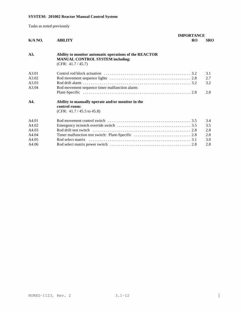
NUREG-1123, Rev. 2 |3.1-12
SYSTEM: 201002 Reactor Manual Control System
Tasks as noted previously
IMPORTANCE K/A NO. ABILITY RO SRO
A3. Ability to monitor automatic operations of the REACTORMANUAL CONTROL SYSTEM including:(CFR: 41.7 / 45.7)
A3.01 Control rod block actuation . . . . . . . . . . . . . . . . . . . . . . . . . . . . . . . . . . . . . . . . . . . . . . 3.2 3.1A3.02 Rod movement sequence lights . . . . . . . . . . . . . . . . . . . . . . . . . . . . . . . . . . . . . . . . . . . 2.8 2.7A3.03 Rod drift alarm . . . . . . . . . . . . . . . . . . . . . . . . . . . . . . . . . . . . . . . . . . . . . . . . . . . . . . . . . 3.2 3.2A3.04 Rod movement sequence timer malfunction alarm:
Plant-Specific . . . . . . . . . . . . . . . . . . . . . . . . . . . . . . . . . . . . . . . . . . . . . . . . . . . . . . . . . 2.8 2.8
A4. Ability to manually operate and/or monitor in thecontrol room:(CFR: 41.7 / 45.5 to 45.8)
A4.01 Rod movement control switch . . . . . . . . . . . . . . . . . . . . . . . . . . . . . . . . . . . . . . . . . . . . 3.5 3.4A4.02 Emergency in/notch override switch . . . . . . . . . . . . . . . . . . . . . . . . . . . . . . . . . . . . . . . 3.5 3.5A4.03 Rod drift test switch . . . . . . . . . . . . . . . . . . . . . . . . . . . . . . . . . . . . . . . . . . . . . . . . . . . . 2.8 2.8A4.04 Timer malfunction test switch: Plant-Specific . . . . . . . . . . . . . . . . . . . . . . . . . . . . . . 2.8 2.8A4.05 Rod select matrix . . . . . . . . . . . . . . . . . . . . . . . . . . . . . . . . . . . . . . . . . . . . . . . . . . . . . . 3.1 3.0A4.06 Rod select matrix power switch . . . . . . . . . . . . . . . . . . . . . . . . . . . . . . . . . . . . . . . . . . . 2.8 2.8

NUREG-1123, Rev. 2 |3.1-13
SYSTEM: 202002 Recirculation Flow Control System
TASK: Adjust the recirculation flow using manual controlOperate recirculation pumps in various control modes (adjust the recirculation flow using "master manual"control)What if flow mismatch exceeds limits of daily surveillance logWhat if power to flow is not in specified range?
IMPORTANCE K/A NO. KNOWLEDGE RO SRO
K1. Knowledge of the physical connections and/or cause-effect relationships between RECIRCULATION FLOWCONTROL SYSTEM and the following:(CFR: 41.2 to 41.9 / 45.7 to 45.8)
K1.01 Recirculation system . . . . . . . . . . . . . . . . . . . . . . . . . . . . . . . . . . . . . . . . . . . . . . . . . . . 3.5 3.6K1.02 Reactor power . . . . . . . . . . . . . . . . . . . . . . . . . . . . . . . . . . . . . . . . . . . . . . . . . . . . . . . . . 4.2* 4.2K1.03 Reactor core flow . . . . . . . . . . . . . . . . . . . . . . . . . . . . . . . . . . . . . . . . . . . . . . . . . . . . . . 3.7 3.7K1.04 Reactor/turbine pressure regulating system: Plant-
Specific . . . . . . . . . . . . . . . . . . . . . . . . . . . . . . . . . . . . . . . . . . . . . . . . . . . . . . . . . . . . . . 3.1 3.1K1.05 Recirculation MG set: Plant-Specific . . . . . . . . . . . . . . . . . . . . . . . . . . . . . . . . . . . . . 3.5 3.5K1.06 A.C. electrical . . . . . . . . . . . . . . . . . . . . . . . . . . . . . . . . . . . . . . . . . . . . . . . . . . . . . . . . . 2.9 3.0K1.07 D.C. electrical . . . . . . . . . . . . . . . . . . . . . . . . . . . . . . . . . . . . . . . . . . . . . . . . . . . . . . . . . 2.6 2.8K1.08 Feedwater flow . . . . . . . . . . . . . . . . . . . . . . . . . . . . . . . . . . . . . . . . . . . . . . . . . . . . . . . . 3.1 3.2K1.09 Reactor water level . . . . . . . . . . . . . . . . . . . . . . . . . . . . . . . . . . . . . . . . . . . . . . . . . . . . . 3.1 3.2Kl.10 Rod pattern . . . . . . . . . . . . . . . . . . . . . . . . . . . . . . . . . . . . . . . . . . . . . . . . . . . . . . . . . . . . 2.5 2.6K1.11 APRM system . . . . . . . . . . . . . . . . . . . . . . . . . . . . . . . . . . . . . . . . . . . . . . . . . . . . . . . . . 3.4 3.4K1.12 Recirculation flow control valves: Plant-Specific . . . . . . . . . . . . . . . . . . . . . . . . . . . 3.7 3.9
K2. Knowledge of electrical power supplies to thefollowing:(CFR: 41.7)
K2.01 Recirculation flow control system . . . . . . . . . . . . . . . . . . . . . . . . . . . . . . . . . . . . . . . . 2.4* 2.4* |K2.02 Hydraulic power unit: Plant-Specific . . . . . . . . . . . . . . . . . . . . . . . . . . . . . . . . . . . . . . 2.6 2.6
K3. Knowledge of the effect that a loss or malfunction ofthe RECIRCULATION FLOW CONTROL SYSTEM will have onfollowing:(CFR: 41.7 / 45.4)
K3.01 Core flow . . . . . . . . . . . . . . . . . . . . . . . . . . . . . . . . . . . . . . . . . . . . . . . . . . . . . . . . . . . . . 3.5 3.5K3.02 Reactor power . . . . . . . . . . . . . . . . . . . . . . . . . . . . . . . . . . . . . . . . . . . . . . . . . . . . . . . . . 4.0 4.0K3.03 Reactor water level . . . . . . . . . . . . . . . . . . . . . . . . . . . . . . . . . . . . . . . . . . . . . . . . . . . . . 3.3 3.4K3.04 Reactor/turbine pressure regulation system . . . . . . . . . . . . . . . . . . . . . . . . . . . . . . . . . 2.9 3.1K3.05 Recirculation pump speed: Plant-Specific . . . . . . . . . . . . . . . . . . . . . . . . . . . . . . . . . . 3.2 3.3K3.06 Recirculation flow control valve position: Plant- Specific . . . . . . . . . . . . . . . . . . . . . . . . . . . . . . . . . . . . . . . . . . . . . . . . . . . . . . . . . . . . . . 3.7 3.7

NUREG-1123, Rev. 2 |3.1-14
SYSTEM: 202002 Recirculation Flow Control System
Tasks as noted previously
IMPORTANCE K/A NO. KNOWLEDGE RO SRO
K4. Knowledge of RECIRCULATION FLOW CONTROL SYSTEM designfeature(s) and/or interlocks which provide for thefollowing:(CFR: 41.7)
K4.01 Scoop tube break: Plant-Specific . . . . . . . . . . . . . . . . . . . . . . . . . . . . . . . . . . . . . . . . . 3.1 3.1K4.02 Recirculation pump speed control: Plant-Specific . . . . . . . . . . . . . . . . . . . . . . . . . . . 3.0 3.0K4.03 Signal failure detection: Plant-Specific . . . . . . . . . . . . . . . . . . . . . . . . . . . . . . . . . . . . 3.0 3.0K4.04 Automatic load following: Plant-Specific . . . . . . . . . . . . . . . . . . . . . . . . . . . . . . . . . . 2.4* 2.4*|K4.05 Limiting recirculation pump speed mismatch: Plant-
Specific . . . . . . . . . . . . . . . . . . . . . . . . . . . . . . . . . . . . . . . . . . . . . . . . . . . . . . . . . . . . . . 3.1 3.4K4.06 Recirculation pump adequate NPSH: Plant-Specific . . . . . . . . . . . . . . . . . . . . . . . . . 3.1 3.1K4.07 Minimum and maximum pump speed setpoints . . . . . . . . . . . . . . . . . . . . . . . . . . . . . . 2.9 2.9K4.08 Automatic flow control valve positioning: BWR-5,6 . . . . . . . . . . . . . . . . . . . . . . . . . 3.3 3.4K4.09 Minimum and maximum flow control valve position
setpoints: BWR-5,6 . . . . . . . . . . . . . . . . . . . . . . . . . . . . . . . . . . . . . . . . . . . . . . . . . . . . 3.3 3.4
K5. Knowledge of the operational implications of thefollowing concepts as they apply to RECIRCULATION FLOWCONTROL SYSTEM :(CFR: 41.5 / 45.3)
K5.01 Fluid coupling: BWR-3,4 . . . . . . . . . . . . . . . . . . . . . . . . . . . . . . . . . . . . . . . . . . . . . . . 2.8 2.8K5.02 Feedback signals . . . . . . . . . . . . . . . . . . . . . . . . . . . . . . . . . . . . . . . . . . . . . . . . . . . . . . . 2.6 2.6K5.03 Error signals . . . . . . . . . . . . . . . . . . . . . . . . . . . . . . . . . . . . . . . . . . . . . . . . . . . . . . . . . . . 2.4 2.4
K6. Knowledge of the effect that a loss or malfunction ofthe following will have on the RECIRCULATION FLOWCONTROL SYSTEM :(CFR: 41.7 / 45.7)
K6.01 A.C. power . . . . . . . . . . . . . . . . . . . . . . . . . . . . . . . . . . . . . . . . . . . . . . . . . . . . . . . . . . . . 2.8 2.9K6.02 D.C. power . . . . . . . . . . . . . . . . . . . . . . . . . . . . . . . . . . . . . . . . . . . . . . . . . . . . . . . . . . . . 2.6 2.6K6.03 Recirculation system . . . . . . . . . . . . . . . . . . . . . . . . . . . . . . . . . . . . . . . . . . . . . . . . . . . 2.8 2.8K6.04 Feedwater flow inputs: BWR-3,4,5,6 . . . . . . . . . . . . . . . . . . . . . . . . . . . . . . . . . . . . . . 3.5 3.5K6.05 Reactor water level . . . . . . . . . . . . . . . . . . . . . . . . . . . . . . . . . . . . . . . . . . . . . . . . . . . . . 3.1 3.1|K6.06 Reactor/turbine pressure regulating system: Plant-
Specific . . . . . . . . . . . . . . . . . . . . . . . . . . . . . . . . . . . . . . . . . . . . . . . . . . . . . . . . . . . . . . 2.9 2.9K6.07 APRM signal input: BWR-5,6 . . . . . . . . . . . . . . . . . . . . . . . . . . . . . . . . . . . . . . . . . . . . 3.6 3.7

NUREG-1123, Rev. 2 |3.1-15
SYSTEM: 202002 Recirculation Flow Control System
Tasks as noted previously
IMPORTANCE K/A NO. ABILITY RO SRO
A1. Ability to predict and/or monitor changes inparameters associated with operating the RECIRCULATIONFLOW CONTROL SYSTEM controls including:(CFR: 41.5 / 45.5)
A1.01 Recirculation pump speed: BWR-2,3,4,5,6 . . . . . . . . . . . . . . . . . . . . . . . . . . . . . . . . . 3.2 3.2A1.02 MG set drive motor amps: Plant-Specific . . . . . . . . . . . . . . . . . . . . . . . . . . . . . . . . . . 2.7 2.7A1.03 MG set generator current, power, voltage . . . . . . . . . . . . . . . . . . . . . . . . . . . . . . . . . . . 2.5* 2.4*A1.04 Reactor water level . . . . . . . . . . . . . . . . . . . . . . . . . . . . . . . . . . . . . . . . . . . . . . . . . . . . . 2.9 2.9A1.05 Reactor power . . . . . . . . . . . . . . . . . . . . . . . . . . . . . . . . . . . . . . . . . . . . . . . . . . . . . . . . . 3.6 3.6A1.06 Reactor core flow . . . . . . . . . . . . . . . . . . . . . . . . . . . . . . . . . . . . . . . . . . . . . . . . . . . . . . 3.4 3.3A1.07 Recirculation loop flow: Plant-Specific . . . . . . . . . . . . . . . . . . . . . . . . . . . . . . . . . . . 3.1 3.1A1.08 Recirculation FCV position: BWR-5,6 . . . . . . . . . . . . . . . . . . . . . . . . . . . . . . . . . . . . 3.4 3.4
A2. Ability to (a) predict the impacts of the following onthe RECIRCULATION FLOW CONTROL SYSTEM ; and (b) basedon those predictions, use procedures to correct,control, or mitigate the consequences of thoseabnormal conditions or operations:(CFR: 41.5 / 45.6)
A2.01 Recirculation pump trip . . . . . . . . . . . . . . . . . . . . . . . . . . . . . . . . . . . . . . . . . . . . . . . . . 3.4 3.4A2.02 Loss of A.C. . . . . . . . . . . . . . . . . . . . . . . . . . . . . . . . . . . . . . . . . . . . . . . . . . . . . . . . . . . . 2.9 3.0A2.03 Loss of D.C. . . . . . . . . . . . . . . . . . . . . . . . . . . . . . . . . . . . . . . . . . . . . . . . . . . . . . . . . . . . 2.6 2.7A2.04 Recirculation pump speed mismatch between loops:
Plant-Specific . . . . . . . . . . . . . . . . . . . . . . . . . . . . . . . . . . . . . . . . . . . . . . . . . . . . . . . . . 3.0 3.2A2.05 Scoop tube lockup: BWR-2,3,4 . . . . . . . . . . . . . . . . . . . . . . . . . . . . . . . . . . . . . . . . . . 3.1 3.1A2.06 Low reactor water level: Plant-Specific . . . . . . . . . . . . . . . . . . . . . . . . . . . . . . . . . . . . 3.3 3.3A2.07 Loss of feedwater signal inputs: Plant-Specific . . . . . . . . . . . . . . . . . . . . . . . . . . . . . 3.3 3.3A2.08 FCV lockup: BWR-5,6 . . . . . . . . . . . . . . . . . . . . . . . . . . . . . . . . . . . . . . . . . . . . . . . . . . 3.3 3.3A2.09 †Recirculation flow mismatch: Plant-Specific . . . . . . . . . . . . . . . . . . . . . . . . . . . . . . 3.1 3.3
A3. Ability to monitor automatic operations of theRECIRCULATION FLOW CONTROL SYSTEM including:(CFR: 41.7 / 45.7)
A3.01 Flow control valve operation: BWR-5,6 . . . . . . . . . . . . . . . . . . . . . . . . . . . . . . . . . . . 3.6 3.4A3.02 Lights and alarms . . . . . . . . . . . . . . . . . . . . . . . . . . . . . . . . . . . . . . . . . . . . . . . . . . . . . . . 3.4 3.4A3.03 Scoop tube operation: BWR-2,3,4 . . . . . . . . . . . . . . . . . . . . . . . . . . . . . . . . . . . . . . . . 3.1 3.0
A4. Ability to manually operate and/or monitor in thecontrol room:(CFR: 41.7 / 45.5 to 45.8)
A4.01 MG sets . . . . . . . . . . . . . . . . . . . . . . . . . . . . . . . . . . . . . . . . . . . . . . . . . . . . . . . . . . . . . . . 3.3 3.1A4.02 Hydraulic power unit: BWR-5,6 . . . . . . . . . . . . . . . . . . . . . . . . . . . . . . . . . . . . . . . . . . . 2.8 2.8A4.03 Lights and alarms . . . . . . . . . . . . . . . . . . . . . . . . . . . . . . . . . . . . . . . . . . . . . . . . . . . . . . . . 3.1 3.1

NUREG-1123, Rev. 2 |3.1-16
A4.04 Reactor power . . . . . . . . . . . . . . . . . . . . . . . . . . . . . . . . . . . . . . . . . . . . . . . . . . . . . . . . . . 3.8 3.8A4.05 Reactor level . . . . . . . . . . . . . . . . . . . . . . . . . . . . . . . . . . . . . . . . . . . . . . . . . . . . . . . . . . . 3.4 3.4A4.06 Scoop tube power: BWR-2,3,4 . . . . . . . . . . . . . . . . . . . . . . . . . . . . . . . . . . . . . . . . . . . . 2.7 2.6A4.07 Recirculation pump speed: BWR-2,3,4,5,6 . . . . . . . . . . . . . . . . . . . . . . . . . . . . . . . . . . 3.3 3.2A4.08 Recirculation system flow . . . . . . . . . . . . . . . . . . . . . . . . . . . . . . . . . . . . . . . . . . . . . . . . 3.3 3.3A4.09 Core flow . . . . . . . . . . . . . . . . . . . . . . . . . . . . . . . . . . . . . . . . . . . . . . . . . . . . . . . . . . . . . . 3.2 3.3
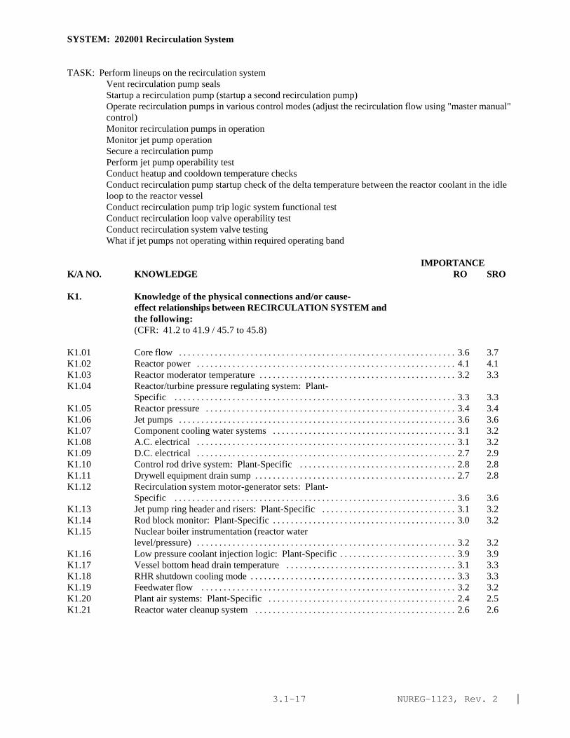
NUREG-1123, Rev. 2 |3.1-17
SYSTEM: 202001 Recirculation System
TASK: Perform lineups on the recirculation system Vent recirculation pump seals Startup a recirculation pump (startup a second recirculation pump)Operate recirculation pumps in various control modes (adjust the recirculation flow using "master manual"control) Monitor recirculation pumps in operation Monitor jet pump operation Secure a recirculation pump Perform jet pump operability test Conduct heatup and cooldown temperature checks Conduct recirculation pump startup check of the delta temperature between the reactor coolant in the idleloop to the reactor vesselConduct recirculation pump trip logic system functional test Conduct recirculation loop valve operability test Conduct recirculation system valve testing What if jet pumps not operating within required operating band
IMPORTANCE K/A NO. KNOWLEDGE RO SRO
K1. Knowledge of the physical connections and/or cause-effect relationships between RECIRCULATION SYSTEM andthe following:(CFR: 41.2 to 41.9 / 45.7 to 45.8)
K1.01 Core flow . . . . . . . . . . . . . . . . . . . . . . . . . . . . . . . . . . . . . . . . . . . . . . . . . . . . . . . . . . . . . . 3.6 3.7K1.02 Reactor power . . . . . . . . . . . . . . . . . . . . . . . . . . . . . . . . . . . . . . . . . . . . . . . . . . . . . . . . . . 4.1 4.1K1.03 Reactor moderator temperature . . . . . . . . . . . . . . . . . . . . . . . . . . . . . . . . . . . . . . . . . . . . 3.2 3.3K1.04 Reactor/turbine pressure regulating system: Plant-
Specific . . . . . . . . . . . . . . . . . . . . . . . . . . . . . . . . . . . . . . . . . . . . . . . . . . . . . . . . . . . . . . . 3.3 3.3K1.05 Reactor pressure . . . . . . . . . . . . . . . . . . . . . . . . . . . . . . . . . . . . . . . . . . . . . . . . . . . . . . . . 3.4 3.4K1.06 Jet pumps . . . . . . . . . . . . . . . . . . . . . . . . . . . . . . . . . . . . . . . . . . . . . . . . . . . . . . . . . . . . . . 3.6 3.6K1.07 Component cooling water systems . . . . . . . . . . . . . . . . . . . . . . . . . . . . . . . . . . . . . . . . . 3.1 3.2K1.08 A.C. electrical . . . . . . . . . . . . . . . . . . . . . . . . . . . . . . . . . . . . . . . . . . . . . . . . . . . . . . . . . . 3.1 3.2K1.09 D.C. electrical . . . . . . . . . . . . . . . . . . . . . . . . . . . . . . . . . . . . . . . . . . . . . . . . . . . . . . . . . . 2.7 2.9K1.10 Control rod drive system: Plant-Specific . . . . . . . . . . . . . . . . . . . . . . . . . . . . . . . . . . . 2.8 2.8K1.11 Drywell equipment drain sump . . . . . . . . . . . . . . . . . . . . . . . . . . . . . . . . . . . . . . . . . . . . . 2.7 2.8K1.12 Recirculation system motor-generator sets: Plant-
Specific . . . . . . . . . . . . . . . . . . . . . . . . . . . . . . . . . . . . . . . . . . . . . . . . . . . . . . . . . . . . . . . 3.6 3.6K1.13 Jet pump ring header and risers: Plant-Specific . . . . . . . . . . . . . . . . . . . . . . . . . . . . . . 3.1 3.2K1.14 Rod block monitor: Plant-Specific . . . . . . . . . . . . . . . . . . . . . . . . . . . . . . . . . . . . . . . . . 3.0 3.2K1.15 Nuclear boiler instrumentation (reactor water
level/pressure) . . . . . . . . . . . . . . . . . . . . . . . . . . . . . . . . . . . . . . . . . . . . . . . . . . . . . . . . . . 3.2 3.2K1.16 Low pressure coolant injection logic: Plant-Specific . . . . . . . . . . . . . . . . . . . . . . . . . . 3.9 3.9K1.17 Vessel bottom head drain temperature . . . . . . . . . . . . . . . . . . . . . . . . . . . . . . . . . . . . . . 3.1 3.3K1.18 RHR shutdown cooling mode . . . . . . . . . . . . . . . . . . . . . . . . . . . . . . . . . . . . . . . . . . . . . . 3.3 3.3K1.19 Feedwater flow . . . . . . . . . . . . . . . . . . . . . . . . . . . . . . . . . . . . . . . . . . . . . . . . . . . . . . . . . 3.2 3.2K1.20 Plant air systems: Plant-Specific . . . . . . . . . . . . . . . . . . . . . . . . . . . . . . . . . . . . . . . . . . 2.4 2.5K1.21 Reactor water cleanup system . . . . . . . . . . . . . . . . . . . . . . . . . . . . . . . . . . . . . . . . . . . . . 2.6 2.6

NUREG-1123, Rev. 2 |3.1-18
SYSTEM: 202001 Recirculation System
Tasks as noted previouslyIMPORTANCE
K/A NO. KNOWLEDGE RO SRO
K1.22 Reactor water level . . . . . . . . . . . . . . . . . . . . . . . . . . . . . . . . . . . . . . . . . . . . . . . . . . . . . 3.5 3.6K1.23 Average power range monitor flow converters: Plant-
Specific . . . . . . . . . . . . . . . . . . . . . . . . . . . . . . . . . . . . . . . . . . . . . . . . . . . . . . . . . . . . . . 3.4 3.5K1.24 Isolation condenser: Plant-Specific . . . . . . . . . . . . . . . . . . . . . . . . . . . . . . . . . . . . . . . 3.4 3.4K1.25 Reactor water sampling system . . . . . . . . . . . . . . . . . . . . . . . . . . . . . . . . . . . . . . . . . . . . 2.6 2.7K1.26 Recirculation flow control system: Plant-Specific . . . . . . . . . . . . . . . . . . . . . . . . . . . 3.6 3.6|K1.27 ATWS circuitry: Plant-Specific . . . . . . . . . . . . . . . . . . . . . . . . . . . . . . . . . . . . . . . . . . 4.1 4.3*|K1.28 End-of-cycle recirculation pump trip circuitry:
Plant-Specific . . . . . . . . . . . . . . . . . . . . . . . . . . . . . . . . . . . . . . . . . . . . . . . . . . . . . . . . . 3.9 4.1
K2. Knowledge of electrical power supplies to thefollowing:(CFR: 41.7)
K2.01 Recirculation pumps: Plant-Specific . . . . . . . . . . . . . . . . . . . . . . . . . . . . . . . . . . . . . . 3.2* 3.2K2.02 MG sets: Plant-Specific . . . . . . . . . . . . . . . . . . . . . . . . . . . . . . . . . . . . . . . . . . . . . . . . 3.2 3.3K2.03 Recirculation system valves . . . . . . . . . . . . . . . . . . . . . . . . . . . . . . . . . . . . . . . . . . . . . . 2.7* 2.8*K2.04 Hydraulic power unit oil pumps: Plant-Specific . . . . . . . . . . . . . . . . . . . . . . . . . . . . . 2.5* 2.5*K2.05 MG set oil pumps: Plant-Specific . . . . . . . . . . . . . . . . . . . . . . . . . . . . . . . . . . . . . . . . 2.3* 2.3*
K3. Knowledge of the effect that a loss or malfunction ofthe RECIRCULATION SYSTEM will have on following:(CFR: 41.7 / 45.4)
K3.01 Core flow . . . . . . . . . . . . . . . . . . . . . . . . . . . . . . . . . . . . . . . . . . . . . . . . . . . . . . . . . . . . . 3.6 3.6K3.02 Load following capabilities: Plant-Specific . . . . . . . . . . . . . . . . . . . . . . . . . . . . . . . . 2.8 2.8K3.03 Reactor power . . . . . . . . . . . . . . . . . . . . . . . . . . . . . . . . . . . . . . . . . . . . . . . . . . . . . . . . . 3.9 3.9K3.04 Reactor water level . . . . . . . . . . . . . . . . . . . . . . . . . . . . . . . . . . . . . . . . . . . . . . . . . . . . . 3.7 3.7K3.05 Recirculation system MG sets: Plant-Specific . . . . . . . . . . . . . . . . . . . . . . . . . . . . . . 3.3 3.3K3.06 Low pressure coolant injection logic: Plant-Specific . . . . . . . . . . . . . . . . . . . . . . . . . 3.7 3.9K3.07 Vessel bottom head drain temperature . . . . . . . . . . . . . . . . . . . . . . . . . . . . . . . . . . . . . . 2.9 2.9K3.08 Shutdown cooling system . . . . . . . . . . . . . . . . . . . . . . . . . . . . . . . . . . . . . . . . . . . . . . . . 2.8 2.9K3.09 Reactor water cleanup system . . . . . . . . . . . . . . . . . . . . . . . . . . . . . . . . . . . . . . . . . . . . 2.4* 2.5*K3.10 Average power range monitor flow converters . . . . . . . . . . . . . . . . . . . . . . . . . . . . . . . 3.3 3.4K3.11 Component cooling water systems . . . . . . . . . . . . . . . . . . . . . . . . . . . . . . . . . . . . . . . . 2.3* 2.3*K3.12 Isolation condenser: Plant-Specific . . . . . . . . . . . . . . . . . . . . . . . . . . . . . . . . . . . . . . . 3.0 3.0K3.13 Reactor water sampling system . . . . . . . . . . . . . . . . . . . . . . . . . . . . . . . . . . . . . . . . . . . 2.5 2.5K3.14 Primary containment integrity: Plant-Specific . . . . . . . . . . . . . . . . . . . . . . . . . . . . . . 3.5 3.5
K4. Knowledge of RECIRCULATION System design feature(s)and/or interlocks which provide for the following:(CFR: 41.7)
K4.01 2/3 core coverage: Plant-Specific . . . . . . . . . . . . . . . . . . . . . . . . . . . . . . . . . . . . . . . . 3.9 3.9K4.02 Adequate recirculation pump NPSH . . . . . . . . . . . . . . . . . . . . . . . . . . . . . . . . . . . . . . . 3.1 3.2K4.03 Recirculation pump motor cooling . . . . . . . . . . . . . . . . . . . . . . . . . . . . . . . . . . . . . . . . 2.8 2.8K4.04 Controlled seal flow . . . . . . . . . . . . . . . . . . . . . . . . . . . . . . . . . . . . . . . . . . . . . . . . . . . . 3.0 3.1K4.05 Seal cooling . . . . . . . . . . . . . . . . . . . . . . . . . . . . . . . . . . . . . . . . . . . . . . . . . . . . . . . . . . . 2.9 2.9

NUREG-1123, Rev. 2 |3.1-19
SYSTEM: 202001 Recirculation System
Tasks as noted previously
IMPORTANCE K/A NO. KNOWLEDGE RO SRO
K4.06 Automatic voltage/frequency regulation: Plant-Specific . . . . . . . . . . . . . . . . . . . . . . . . . . . . . . . . . . . . . . . . . . . . . . . . . . . . . . . . . . . . . . 2.6* 2.7
K4.07 Motor generator set trips: Plant-Specific . . . . . . . . . . . . . . . . . . . . . . . . . . . . . . . . . . 2.8 2.9K4.08 Oil pump automatic starts: Plant-Specific . . . . . . . . . . . . . . . . . . . . . . . . . . . . . . . . . . 2.8 2.9K4.09 Pump minimum flow limit: Plant-Specific . . . . . . . . . . . . . . . . . . . . . . . . . . . . . . . . . 2.7 2.9K4.10 Pump start permissives: Plant-Specific . . . . . . . . . . . . . . . . . . . . . . . . . . . . . . . . . . . . 3.3 3.4K4.11 Limitation of recirculation pumps flow mismatch:
Plant-Specific . . . . . . . . . . . . . . . . . . . . . . . . . . . . . . . . . . . . . . . . . . . . . . . . . . . . . . . . . 3.1 3.5K4.12 Minimization of reactor vessel bottom head temperature
gradients: Plant-Specific . . . . . . . . . . . . . . . . . . . . . . . . . . . . . . . . . . . . . . . . . . . . . . . . 3.2 3.5K4.13 †End of cycle recirculation pump trip: Plant-Specific . . . . . . . . . . . . . . . . . . . . . . . . 3.7 4.0*K4.14 ATWS: Plant-Specific . . . . . . . . . . . . . . . . . . . . . . . . . . . . . . . . . . . . . . . . . . . . . . . . . . 4.0 4.1*K4.15 Slow speed pump start: Plant-Specific . . . . . . . . . . . . . . . . . . . . . . . . . . . . . . . . . . . . . 3.1 3.4K4.16 Recirculation pump downshift/runback: Plant-Specific . . . . . . . . . . . . . . . . . . . . . . . 3.3 3.6K4.17 Fast speed pump start: Plant-Specific . . . . . . . . . . . . . . . . . . . . . . . . . . . . . . . . . . . . . 3.3 3.5K4.18 Automatic MG set start sequencing: Plant-Specific . . . . . . . . . . . . . . . . . . . . . . . . . . 2.8 3.0
K5. Knowledge of the operational implications of thefollowing concepts as they apply to RECIRCULATIONSYSTEM :(CFR: 41.5 / 45.3)
K5.01 Indications of pump cavitation . . . . . . . . . . . . . . . . . . . . . . . . . . . . . . . . . . . . . . . . . . . . 2.7 2.8K5.02 Jet pump operation: BWR-3,4,5,6 . . . . . . . . . . . . . . . . . . . . . . . . . . . . . . . . . . . . . . . . 3.1 3.2K5.03 Pump/motor cooling: Plant-Specific . . . . . . . . . . . . . . . . . . . . . . . . . . . . . . . . . . . . . . 2.7 2.7K5.04 System venting . . . . . . . . . . . . . . . . . . . . . . . . . . . . . . . . . . . . . . . . . . . . . . . . . . . . . . . . . 2.4 2.6K5.05 End of cycle recirculation pump trip: Plant-Specific . . . . . . . . . . . . . . . . . . . . . . . . . 3.5 3.6K5.06 ATWS RPT: Plant-Specific . . . . . . . . . . . . . . . . . . . . . . . . . . . . . . . . . . . . . . . . . . . . . . 3.6 3.7K5.07 Natural circulation: Plant-Specific . . . . . . . . . . . . . . . . . . . . . . . . . . . . . . . . . . . . . . . . 3.3 3.4K5.08 E/P converters: Plant-Specific . . . . . . . . . . . . . . . . . . . . . . . . . . . . . . . . . . . . . . . . . . . 2.0* 2.1*K5.09 Hydraulically operated valves: Plant-Specific . . . . . . . . . . . . . . . . . . . . . . . . . . . . . . . 2.6* 2.6*K5.10 Motor generator set operation: Plant-Specific . . . . . . . . . . . . . . . . . . . . . . . . . . . . . . 2.8* 2.8
K6. Knowledge of the effect that a loss or malfunction ofthe following will have on the RECIRCULATION SYSTEM :(CFR: 41.7 / 45.7)
K6.01 Jet pumps: Plant-Specific . . . . . . . . . . . . . . . . . . . . . . . . . . . . . . . . . . . . . . . . . . . . . . . 3.5 3.7K6.02 Component cooling water systems . . . . . . . . . . . . . . . . . . . . . . . . . . . . . . . . . . . . . . . . 3.1 3.2K6.03 A.C. power: Plant-Specific . . . . . . . . . . . . . . . . . . . . . . . . . . . . . . . . . . . . . . . . . . . . . . 2.9 3.0K6.04 D.C. power: Plant-Specific . . . . . . . . . . . . . . . . . . . . . . . . . . . . . . . . . . . . . . . . . . . . . . 2.7 2.8K6.05 Control rod drive system: Plant-Specific . . . . . . . . . . . . . . . . . . . . . . . . . . . . . . . . . . 2.7 2.8K6.06 Recirculation system motor-generator sets: Plant-
Specific . . . . . . . . . . . . . . . . . . . . . . . . . . . . . . . . . . . . . . . . . . . . . . . . . . . . . . . . . . . . . . 3.1 3.1K6.07 Feedwater flow . . . . . . . . . . . . . . . . . . . . . . . . . . . . . . . . . . . . . . . . . . . . . . . . . . . . . . . . 3.3 3.3K6.08 Reactor water cleanup system . . . . . . . . . . . . . . . . . . . . . . . . . . . . . . . . . . . . . . . . . . . . 2.3 2.3K6.09 Reactor water level . . . . . . . . . . . . . . . . . . . . . . . . . . . . . . . . . . . . . . . . . . . . . . . . . . . . . 3.4 3.4
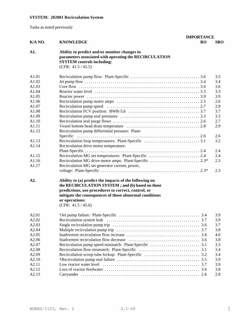
NUREG-1123, Rev. 2 |3.1-20
SYSTEM: 202001 Recirculation System
Tasks as noted previously
IMPORTANCE K/A NO. KNOWLEDGE RO SRO
A1. Ability to predict and/or monitor changes inparameters associated with operating the RECIRCULATIONSYSTEM controls including:(CFR: 41.5 / 45.5)
A1.01 Recirculation pump flow: Plant-Specific . . . . . . . . . . . . . . . . . . . . . . . . . . . . . . . . . . . 3.6 3.5A1.02 Jet pump flow . . . . . . . . . . . . . . . . . . . . . . . . . . . . . . . . . . . . . . . . . . . . . . . . . . . . . . . . . . 3.4 3.4A1.03 Core flow . . . . . . . . . . . . . . . . . . . . . . . . . . . . . . . . . . . . . . . . . . . . . . . . . . . . . . . . . . . . . 3.6 3.6A1.04 Reactor water level . . . . . . . . . . . . . . . . . . . . . . . . . . . . . . . . . . . . . . . . . . . . . . . . . . . . . 3.3 3.3A1.05 Reactor power . . . . . . . . . . . . . . . . . . . . . . . . . . . . . . . . . . . . . . . . . . . . . . . . . . . . . . . . . 3.9 3.9A1.06 Recirculation pump motor amps . . . . . . . . . . . . . . . . . . . . . . . . . . . . . . . . . . . . . . . . . . 2.5 2.6A1.07 Recirculation pump speed . . . . . . . . . . . . . . . . . . . . . . . . . . . . . . . . . . . . . . . . . . . . . . . 2.7 2.8A1.08 Recirculation FCV position: BWR-5,6 . . . . . . . . . . . . . . . . . . . . . . . . . . . . . . . . . . . . 3.7 3.7A1.09 Recirculation pump seal pressures . . . . . . . . . . . . . . . . . . . . . . . . . . . . . . . . . . . . . . . . 3.3 3.3A1.10 Recirculation seal purge flows . . . . . . . . . . . . . . . . . . . . . . . . . . . . . . . . . . . . . . . . . . . . 2.6 2.7A1.11 Vessel bottom head drain temperature . . . . . . . . . . . . . . . . . . . . . . . . . . . . . . . . . . . . . 2.8 2.9A1.12 Recirculation pump differential pressure: Plant-
Specific . . . . . . . . . . . . . . . . . . . . . . . . . . . . . . . . . . . . . . . . . . . . . . . . . . . . . . . . . . . . . . 2.6 2.6A1.13 Recirculation loop temperatures: Plant-Specific . . . . . . . . . . . . . . . . . . . . . . . . . . . . 3.1 3.2A1.14 Recirculation drive motor temperature:
Plant-Specific . . . . . . . . . . . . . . . . . . . . . . . . . . . . . . . . . . . . . . . . . . . . . . . . . . . . . . . . . . 2.4 2.4A1.15 Recirculation MG set temperatures: Plant-Specific . . . . . . . . . . . . . . . . . . . . . . . . . . 2.4 2.4A1.16 Recirculation MG drive motor amps: Plant-Specific . . . . . . . . . . . . . . . . . . . . . . . . . 2.3* 2.3A1.17 Recirculation MG set generator current, power,
voltage: Plant-Specific . . . . . . . . . . . . . . . . . . . . . . . . . . . . . . . . . . . . . . . . . . . . . . . . . . 2.3* 2.3
A2. Ability to (a) predict the impacts of the following onthe RECIRCULATION SYSTEM ; and (b) based on thosepredictions, use procedures to correct, control, ormitigate the consequences of those abnormal conditionsor operations:(CFR: 41.5 / 45.6)
A2.01 †Jet pump failure: Plant-Specific . . . . . . . . . . . . . . . . . . . . . . . . . . . . . . . . . . . . . . . . . 3.4 3.9A2.02 Recirculation system leak . . . . . . . . . . . . . . . . . . . . . . . . . . . . . . . . . . . . . . . . . . . . . . . 3.7 3.9A2.03 Single recirculation pump trip . . . . . . . . . . . . . . . . . . . . . . . . . . . . . . . . . . . . . . . . . . . . 3.6 3.7A2.04 Multiple recirculation pump trip . . . . . . . . . . . . . . . . . . . . . . . . . . . . . . . . . . . . . . . . . . 3.7 3.8A2.05 Inadvertent recirculation flow increase . . . . . . . . . . . . . . . . . . . . . . . . . . . . . . . . . . . . . 3.8 4.0A2.06 Inadvertent recirculation flow decrease . . . . . . . . . . . . . . . . . . . . . . . . . . . . . . . . . . . . 3.6 3.8A2.07 Recirculation pump speed mismatch: Plant-Specific . . . . . . . . . . . . . . . . . . . . . . . . . 3.1 3.3A2.08 Recirculation flow mismatch: Plant-Specific . . . . . . . . . . . . . . . . . . . . . . . . . . . . . . . 3.1 3.4A2.09 Recirculation scoop tube lockup: Plant-Specific . . . . . . . . . . . . . . . . . . . . . . . . . . . . 3.2 3.4A2.10 †Recirculation pump seal failure . . . . . . . . . . . . . . . . . . . . . . . . . . . . . . . . . . . . . . . . . . 3.5 3.9A2.11 Low reactor water level . . . . . . . . . . . . . . . . . . . . . . . . . . . . . . . . . . . . . . . . . . . . . . . . . 3.7 3.9A2.12 Loss of reactor feedwater . . . . . . . . . . . . . . . . . . . . . . . . . . . . . . . . . . . . . . . . . . . . . . . . 3.6 3.8A2.13 Carryunder . . . . . . . . . . . . . . . . . . . . . . . . . . . . . . . . . . . . . . . . . . . . . . . . . . . . . . . . . . . . 2.6 2.8

NUREG-1123, Rev. 2 |3.1-21
SYSTEM: 202001 Recirculation System
Tasks as noted previously
IMPORTANCE K/A NO. KNOWLEDGE RO SRO
A2.14 High reactor pressure (ATWS circuitry initiation):Plant-Specific . . . . . . . . . . . . . . . . . . . . . . . . . . . . . . . . . . . . . . . . . . . . . . . . . . . . . . . . . . 3.9 4.2* |
A2.15 End of cycle trip circuitry: Plant-Specific . . . . . . . . . . . . . . . . . . . . . . . . . . . . . . . . . . . 3.7 3.9A2.16 Loss of seal purge flow (CRD) . . . . . . . . . . . . . . . . . . . . . . . . . . . . . . . . . . . . . . . . . . . . 2.9 3.1A2.17 Loss of seal cooling water . . . . . . . . . . . . . . . . . . . . . . . . . . . . . . . . . . . . . . . . . . . . . . . . 3.1 3.2A2.18 Loss of motor cooling . . . . . . . . . . . . . . . . . . . . . . . . . . . . . . . . . . . . . . . . . . . . . . . . . . . 2.9 3.1A2.19 Loss of A.C. power: Plant-Specific . . . . . . . . . . . . . . . . . . . . . . . . . . . . . . . . . . . . . . . . . 3.1 3.2A2.20 Loss of D.C. power: Plant-Specific . . . . . . . . . . . . . . . . . . . . . . . . . . . . . . . . . . . . . . . . 2.8 2.9A2.21 †Recirculation loop temperature out of spec: Plant-
Specific . . . . . . . . . . . . . . . . . . . . . . . . . . . . . . . . . . . . . . . . . . . . . . . . . . . . . . . . . . . . . . . 3.3 3.7 |A2.22 Loss of component cooling water . . . . . . . . . . . . . . . . . . . . . . . . . . . . . . . . . . . . . . . . . . 3.1 3.2A2.23 Valve closures . . . . . . . . . . . . . . . . . . . . . . . . . . . . . . . . . . . . . . . . . . . . . . . . . . . . . . . . . . 3.2 3.2A2.24 Valve opening . . . . . . . . . . . . . . . . . . . . . . . . . . . . . . . . . . . . . . . . . . . . . . . . . . . . . . . . . . . 3.1 3.1A2.25 Recirculation flow control valve lockup: Plant-
Specific . . . . . . . . . . . . . . . . . . . . . . . . . . . . . . . . . . . . . . . . . . . . . . . . . . . . . . . . . . . . . . . 3.3 3.3A2.26 Incomplete start sequence: Plant-Specific . . . . . . . . . . . . . . . . . . . . . . . . . . . . . . . . . . 2.9 3.1
A3. Ability to monitor automatic operations of theRECIRCULATION SYSTEM including:(CFR: 41.7 / 45.7)
A3.01 Valve operation . . . . . . . . . . . . . . . . . . . . . . . . . . . . . . . . . . . . . . . . . . . . . . . . . . . . . . . . . 3.1 3.1A3.02 Pump/MG set start sequence: Plant-Specific . . . . . . . . . . . . . . . . . . . . . . . . . . . . . . . . 3.1 3.0A3.03 System flow . . . . . . . . . . . . . . . . . . . . . . . . . . . . . . . . . . . . . . . . . . . . . . . . . . . . . . . . . . . . 3.2 3.2A3.04 Lights and alarms . . . . . . . . . . . . . . . . . . . . . . . . . . . . . . . . . . . . . . . . . . . . . . . . . . . . . . . . 3.2 3.1A3.05 Pump speed: Plant-Specific . . . . . . . . . . . . . . . . . . . . . . . . . . . . . . . . . . . . . . . . . . . . . . 2.9 2.9A3.06 Flow control valve position: BWR-5,6 . . . . . . . . . . . . . . . . . . . . . . . . . . . . . . . . . . . . . 3.6 3.6A3.07 Pump trips: Plant-Specific . . . . . . . . . . . . . . . . . . . . . . . . . . . . . . . . . . . . . . . . . . . . . . . 3.3 3.3A3.08 Pump downshift: BWR-5,6 . . . . . . . . . . . . . . . . . . . . . . . . . . . . . . . . . . . . . . . . . . . . . . . 3.4 3.3A3.09 MG set trip: Plant-Specific . . . . . . . . . . . . . . . . . . . . . . . . . . . . . . . . . . . . . . . . . . . . . . . 3.3 3.3
A4. Ability to manually operate and/or monitor in thecontrol room:(CFR: 41.7 / 45.5 to 45.8)
A4.01 Recirculation pumps . . . . . . . . . . . . . . . . . . . . . . . . . . . . . . . . . . . . . . . . . . . . . . . . . . . . . 3.7 3.7A4.02 System valves . . . . . . . . . . . . . . . . . . . . . . . . . . . . . . . . . . . . . . . . . . . . . . . . . . . . . . . . . . . 3.5 3.4A4.03 Reactor power . . . . . . . . . . . . . . . . . . . . . . . . . . . . . . . . . . . . . . . . . . . . . . . . . . . . . . . . . . 4.1 4.1A4.04 System flow . . . . . . . . . . . . . . . . . . . . . . . . . . . . . . . . . . . . . . . . . . . . . . . . . . . . . . . . . . . . 3.7 3.7A4.05 Lights and alarms . . . . . . . . . . . . . . . . . . . . . . . . . . . . . . . . . . . . . . . . . . . . . . . . . . . . . . . . 3.3 3.3A4.06 Oil pumps . . . . . . . . . . . . . . . . . . . . . . . . . . . . . . . . . . . . . . . . . . . . . . . . . . . . . . . . . . . . . . 2.7 2.7A4.07 Vent fans: Plant-Specific . . . . . . . . . . . . . . . . . . . . . . . . . . . . . . . . . . . . . . . . . . . . . . . . . 2.4 2.3A4.08 Motor-generator sets: Plant-Specific . . . . . . . . . . . . . . . . . . . . . . . . . . . . . . . . . . . . . . 3.2 3.1A4.09 Reactor water level . . . . . . . . . . . . . . . . . . . . . . . . . . . . . . . . . . . . . . . . . . . . . . . . . . . . . . 3.7 3.7A4.10 Seal flow: Plant-Specific . . . . . . . . . . . . . . . . . . . . . . . . . . . . . . . . . . . . . . . . . . . . . . . . . 2.8 2.8A4.11 Seal pressures: Plant-Specific . . . . . . . . . . . . . . . . . . . . . . . . . . . . . . . . . . . . . . . . . . . . 3.2 3.3A4.12 Core flow . . . . . . . . . . . . . . . . . . . . . . . . . . . . . . . . . . . . . . . . . . . . . . . . . . . . . . . . . . . . . . 3.9 3.8A4.13 Core differential pressure . . . . . . . . . . . . . . . . . . . . . . . . . . . . . . . . . . . . . . . . . . . . . . . . 3.1 3.3
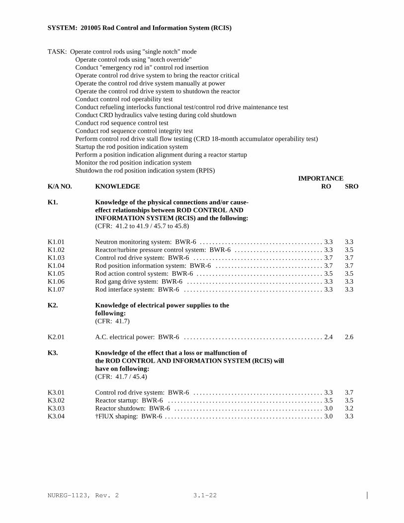
NUREG-1123, Rev. 2 |3.1-22
SYSTEM: 201005 Rod Control and Information System (RCIS)
TASK: Operate control rods using "single notch" mode Operate control rods using "notch override" Conduct "emergency rod in" control rod insertion Operate control rod drive system to bring the reactor critical Operate the control rod drive system manually at power Operate the control rod drive system to shutdown the reactor Conduct control rod operability test Conduct refueling interlocks functional test/control rod drive maintenance test Conduct CRD hydraulics valve testing during cold shutdown Conduct rod sequence control test Conduct rod sequence control integrity test Perform control rod drive stall flow testing (CRD 18-month accumulator operability test) Startup the rod position indication system Perform a position indication alignment during a reactor startup Monitor the rod position indication system Shutdown the rod position indication system (RPIS)
IMPORTANCE K/A NO. KNOWLEDGE RO SRO
K1. Knowledge of the physical connections and/or cause-effect relationships between ROD CONTROL ANDINFORMATION SYSTEM (RCIS) and the following:(CFR: 41.2 to 41.9 / 45.7 to 45.8)
K1.01 Neutron monitoring system: BWR-6 . . . . . . . . . . . . . . . . . . . . . . . . . . . . . . . . . . . . . . . 3.3 3.3K1.02 Reactor/turbine pressure control system: BWR-6 . . . . . . . . . . . . . . . . . . . . . . . . . . . . 3.3 3.5K1.03 Control rod drive system: BWR-6 . . . . . . . . . . . . . . . . . . . . . . . . . . . . . . . . . . . . . . . . . 3.7 3.7K1.04 Rod position information system: BWR-6 . . . . . . . . . . . . . . . . . . . . . . . . . . . . . . . . . . 3.7 3.7K1.05 Rod action control system: BWR-6 . . . . . . . . . . . . . . . . . . . . . . . . . . . . . . . . . . . . . . . . 3.5 3.5K1.06 Rod gang drive system: BWR-6 . . . . . . . . . . . . . . . . . . . . . . . . . . . . . . . . . . . . . . . . . . . 3.3 3.3K1.07 Rod interface system: BWR-6 . . . . . . . . . . . . . . . . . . . . . . . . . . . . . . . . . . . . . . . . . . . . 3.3 3.3
K2. Knowledge of electrical power supplies to thefollowing:(CFR: 41.7)
K2.01 A.C. electrical power: BWR-6 . . . . . . . . . . . . . . . . . . . . . . . . . . . . . . . . . . . . . . . . . . . . 2.4 2.6
K3. Knowledge of the effect that a loss or malfunction ofthe ROD CONTROL AND INFORMATION SYSTEM (RCIS) willhave on following:(CFR: 41.7 / 45.4)
K3.01 Control rod drive system: BWR-6 . . . . . . . . . . . . . . . . . . . . . . . . . . . . . . . . . . . . . . . . . 3.3 3.7K3.02 Reactor startup: BWR-6 . . . . . . . . . . . . . . . . . . . . . . . . . . . . . . . . . . . . . . . . . . . . . . . . . 3.5 3.5K3.03 Reactor shutdown: BWR-6 . . . . . . . . . . . . . . . . . . . . . . . . . . . . . . . . . . . . . . . . . . . . . . . 3.0 3.2K3.04 †FlUX shaping: BWR-6 . . . . . . . . . . . . . . . . . . . . . . . . . . . . . . . . . . . . . . . . . . . . . . . . . . 3.0 3.3

NUREG-1123, Rev. 2 |3.1-23
SYSTEM: 201005 Rod Control and Information System (RCIS)
Tasks as noted previously
IMPORTANCE K/A NO. KNOWLEDGE RO SRO
K4. Knowledge of ROD CONTROL AND INFORMATION SYSTEM (RCIS)design feature(s) and/or interlocks which provide forthe following:(CFR: 41.7)
K4.01 Limiting the effects of a control Rod accident: BWR-6 . . . . . . . . . . . . . . . . . . . . . . . 3.2 3.2K4.02 Bank position withdrawal sequence (BPWS): BWR-6 . . . . . . . . . . . . . . . . . . . . . . . . 3.3 3.3K4.03 Rod withdrawal block signals: BWR-6 . . . . . . . . . . . . . . . . . . . . . . . . . . . . . . . . . . . . . 3.5 3.5K4.04 Rod insertion block signals: BWR-6 . . . . . . . . . . . . . . . . . . . . . . . . . . . . . . . . . . . . . . 3.5 3.5K4.05 Rod withdrawal limiter: BWR-6 . . . . . . . . . . . . . . . . . . . . . . . . . . . . . . . . . . . . . . . . . . 3.5 3.5K4.06 Rod pattern controller rod blocks: BWR-6 . . . . . . . . . . . . . . . . . . . . . . . . . . . . . . . . . 3.5 3.5
K5. Knowledge of the operational implications of thefollowing concepts as they apply to ROD CONTROL ANDINFORMATION SYSTEM (RCIS) :(CFR: 41.5 / 45.3)
K5.01 †Rod pattern and program development: BWR-6 . . . . . . . . . . . . . . . . . . . . . . . . . . . . 2.3 3.2K5.02 Rod pattern controller (RPC): BWR-6 . . . . . . . . . . . . . . . . . . . . . . . . . . . . . . . . . . . . 2.8 3.3K5.03 Rod groups: BWR-6 . . . . . . . . . . . . . . . . . . . . . . . . . . . . . . . . . . . . . . . . . . . . . . . . . . . . 2.3 2.7K5.04 †Rod sequences: BWR-6 . . . . . . . . . . . . . . . . . . . . . . . . . . . . . . . . . . . . . . . . . . . . . . . 2.7 3.0K5.05 Rod density: BWR-6 . . . . . . . . . . . . . . . . . . . . . . . . . . . . . . . . . . . . . . . . . . . . . . . . . . . 2.7 3.0K5.06 Target rod pattern: BWR-6 . . . . . . . . . . . . . . . . . . . . . . . . . . . . . . . . . . . . . . . . . . . . . . 2.8 2.8K5.07 Low power alarm point: BWR-6 . . . . . . . . . . . . . . . . . . . . . . . . . . . . . . . . . . . . . . . . . . 3.5 3.5K5.08 Transition zone: BWR-6 . . . . . . . . . . . . . . . . . . . . . . . . . . . . . . . . . . . . . . . . . . . . . . . . 3.2 3.5K5.09 High power setpoints BWR-6 . . . . . . . . . . . . . . . . . . . . . . . . . . . . . . . . . . . . . . . . . . . . 3.5 3.5 |K5.10 Rod withdrawal limiter: BWR-6 . . . . . . . . . . . . . . . . . . . . . . . . . . . . . . . . . . . . . . . . . . 3.2 3.3K5.11 Control rod motion: BWR-6 . . . . . . . . . . . . . . . . . . . . . . . . . . . . . . . . . . . . . . . . . . . . . 3.3 3.3K5.12 Command word generation and sequencing (operator follow, scan and test): BWR-6 . . . . . . . . . . . . . . . . . . . . . . . . . . . . . . . . . . . . . . . . . . . 1.8* 2.2*K5.13 Position indication probes: BWR-6 . . . . . . . . . . . . . . . . . . . . . . . . . . . . . . . . . . . . . . . 2.5 2.7
K6. Knowledge of the effect that a loss or malfunction ofthe following will have on the ROD CONTROL ANDINFORMATION SYSTEM (RCIS) :(CFR: 41.7 / 45.7)
K6.01 First stage shell pressure or opening of a bypassvalve(s): BWR-6 . . . . . . . . . . . . . . . . . . . . . . . . . . . . . . . . . . . . . . . . . . . . . . . . . . . . . . . 3.2 3.2
K6.02 Rod position signal: BWR-6 . . . . . . . . . . . . . . . . . . . . . . . . . . . . . . . . . . . . . . . . . . . . . 3.2 3.3K6.03 A.C. electrical power: BWR-6 . . . . . . . . . . . . . . . . . . . . . . . . . . . . . . . . . . . . . . . . . . . 2.5 2.8K6.04 IRM channel: BWR-6 . . . . . . . . . . . . . . . . . . . . . . . . . . . . . . . . . . . . . . . . . . . . . . . . . . 3.0 3.2K6.05 SRM channel: BWR-6 . . . . . . . . . . . . . . . . . . . . . . . . . . . . . . . . . . . . . . . . . . . . . . . . . . 3.0 3.2K6.06 APRM channel: BWR-6 . . . . . . . . . . . . . . . . . . . . . . . . . . . . . . . . . . . . . . . . . . . . . . . . 3.0 3.0
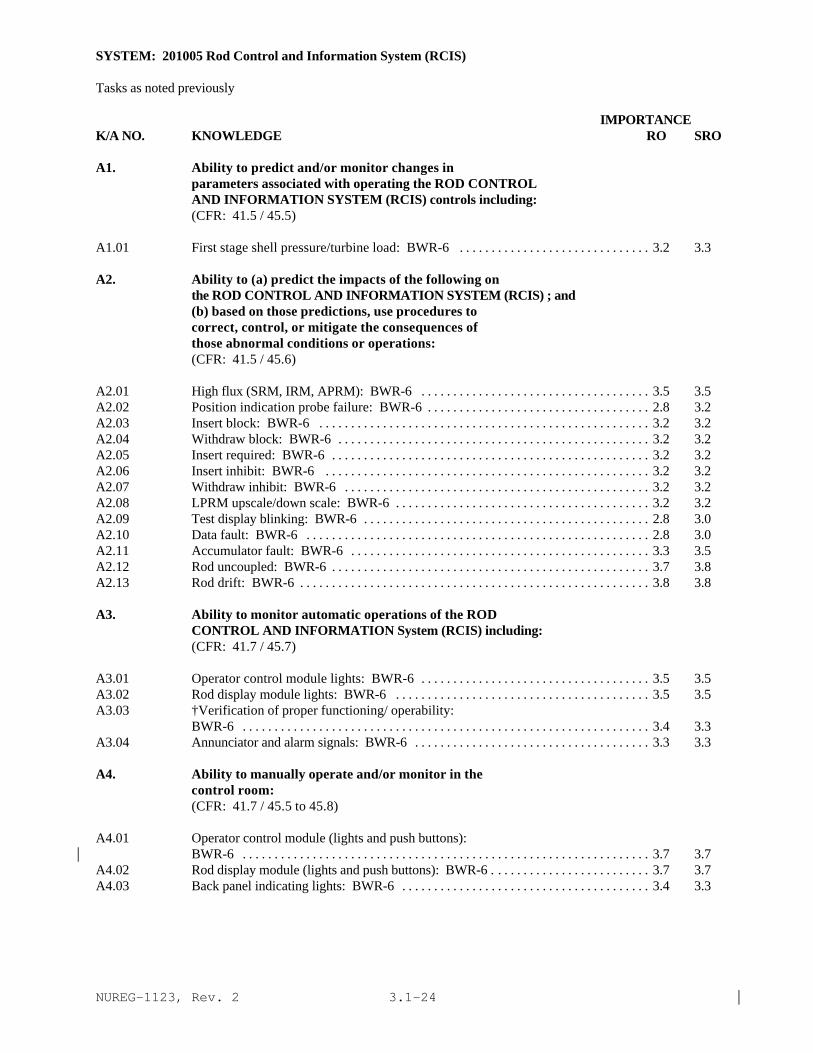
NUREG-1123, Rev. 2 |3.1-24
SYSTEM: 201005 Rod Control and Information System (RCIS)
Tasks as noted previously
IMPORTANCE K/A NO. KNOWLEDGE RO SRO
A1. Ability to predict and/or monitor changes inparameters associated with operating the ROD CONTROLAND INFORMATION SYSTEM (RCIS) controls including:(CFR: 41.5 / 45.5)
A1.01 First stage shell pressure/turbine load: BWR-6 . . . . . . . . . . . . . . . . . . . . . . . . . . . . . . 3.2 3.3
A2. Ability to (a) predict the impacts of the following onthe ROD CONTROL AND INFORMATION SYSTEM (RCIS) ; and(b) based on those predictions, use procedures tocorrect, control, or mitigate the consequences ofthose abnormal conditions or operations:(CFR: 41.5 / 45.6)
A2.01 High flux (SRM, IRM, APRM): BWR-6 . . . . . . . . . . . . . . . . . . . . . . . . . . . . . . . . . . . . 3.5 3.5A2.02 Position indication probe failure: BWR-6 . . . . . . . . . . . . . . . . . . . . . . . . . . . . . . . . . . . 2.8 3.2A2.03 Insert block: BWR-6 . . . . . . . . . . . . . . . . . . . . . . . . . . . . . . . . . . . . . . . . . . . . . . . . . . . . 3.2 3.2A2.04 Withdraw block: BWR-6 . . . . . . . . . . . . . . . . . . . . . . . . . . . . . . . . . . . . . . . . . . . . . . . . . 3.2 3.2A2.05 Insert required: BWR-6 . . . . . . . . . . . . . . . . . . . . . . . . . . . . . . . . . . . . . . . . . . . . . . . . . . 3.2 3.2A2.06 Insert inhibit: BWR-6 . . . . . . . . . . . . . . . . . . . . . . . . . . . . . . . . . . . . . . . . . . . . . . . . . . . 3.2 3.2A2.07 Withdraw inhibit: BWR-6 . . . . . . . . . . . . . . . . . . . . . . . . . . . . . . . . . . . . . . . . . . . . . . . . 3.2 3.2A2.08 LPRM upscale/down scale: BWR-6 . . . . . . . . . . . . . . . . . . . . . . . . . . . . . . . . . . . . . . . . 3.2 3.2A2.09 Test display blinking: BWR-6 . . . . . . . . . . . . . . . . . . . . . . . . . . . . . . . . . . . . . . . . . . . . . 2.8 3.0A2.10 Data fault: BWR-6 . . . . . . . . . . . . . . . . . . . . . . . . . . . . . . . . . . . . . . . . . . . . . . . . . . . . . . 2.8 3.0A2.11 Accumulator fault: BWR-6 . . . . . . . . . . . . . . . . . . . . . . . . . . . . . . . . . . . . . . . . . . . . . . . 3.3 3.5A2.12 Rod uncoupled: BWR-6 . . . . . . . . . . . . . . . . . . . . . . . . . . . . . . . . . . . . . . . . . . . . . . . . . . 3.7 3.8A2.13 Rod drift: BWR-6 . . . . . . . . . . . . . . . . . . . . . . . . . . . . . . . . . . . . . . . . . . . . . . . . . . . . . . . 3.8 3.8
A3. Ability to monitor automatic operations of the RODCONTROL AND INFORMATION System (RCIS) including:(CFR: 41.7 / 45.7)
A3.01 Operator control module lights: BWR-6 . . . . . . . . . . . . . . . . . . . . . . . . . . . . . . . . . . . . 3.5 3.5A3.02 Rod display module lights: BWR-6 . . . . . . . . . . . . . . . . . . . . . . . . . . . . . . . . . . . . . . . . 3.5 3.5A3.03 †Verification of proper functioning/ operability:
BWR-6 . . . . . . . . . . . . . . . . . . . . . . . . . . . . . . . . . . . . . . . . . . . . . . . . . . . . . . . . . . . . . . . . 3.4 3.3A3.04 Annunciator and alarm signals: BWR-6 . . . . . . . . . . . . . . . . . . . . . . . . . . . . . . . . . . . . . 3.3 3.3
A4. Ability to manually operate and/or monitor in thecontrol room:(CFR: 41.7 / 45.5 to 45.8)
A4.01 Operator control module (lights and push buttons):BWR-6 . . . . . . . . . . . . . . . . . . . . . . . . . . . . . . . . . . . . . . . . . . . . . . . . . . . . . . . . . . . . . . . . 3.7 3.7|
A4.02 Rod display module (lights and push buttons): BWR-6 . . . . . . . . . . . . . . . . . . . . . . . . . 3.7 3.7A4.03 Back panel indicating lights: BWR-6 . . . . . . . . . . . . . . . . . . . . . . . . . . . . . . . . . . . . . . . 3.4 3.3

NUREG-1123, Rev. 2 |3.1-25
SYSTEM: 211000 Standby Liquid Control System
TASK: Perform lineups on the standby liquid control system Charge the standby liquid control tank Place the standby liquid control system in standby readiness Monitor the standby liquid control system Inject poison solution into the reactor vessel Purge the standby liquid control tank level indicator Perform standby liquid control recirculation test Perform standby liquid control relief valve test Perform standby liquid control and demineralized water injection reactor vessel test Perform standby liquid control explosive valve inspection Perform standby liquid control component inoperable test
IMPORTANCE K/A NO. KNOWLEDGE RO SRO
K1. Knowledge of the physical connections and/or cause-effect relationships between STANDBY LIQUID CONTROLSYSTEM and the following:(CFR: 41.2 to 41.9 / 45.7 to 45.8)
K1.01 Core spray line break detection: Plant-Specific . . . . . . . . . . . . . . . . . . . . . . . . . . . . . 3.0* 3.3*K1.02 Core plate differential pressure indication . . . . . . . . . . . . . . . . . . . . . . . . . . . . . . . . . . 2.7 2.7K1.03 Plant air systems: Plant-Specific . . . . . . . . . . . . . . . . . . . . . . . . . . . . . . . . . . . . . . . . . 2.5 2.6K1.04 Demineralized water/ condensate storage system . . . . . . . . . . . . . . . . . . . . . . . . . . . . 2.2* 2.3*K1.05 RWCU . . . . . . . . . . . . . . . . . . . . . . . . . . . . . . . . . . . . . . . . . . . . . . . . . . . . . . . . . . . . . . . 3.4 3.6K1.06 Reactor vessel . . . . . . . . . . . . . . . . . . . . . . . . . . . . . . . . . . . . . . . . . . . . . . . . . . . . . . . . . 3.7 3.7K1.07 Jet pump differential pressure indication: Plant-
Specific . . . . . . . . . . . . . . . . . . . . . . . . . . . . . . . . . . . . . . . . . . . . . . . . . . . . . . . . . . . . . . 2.6 2.6K1.08 CRD drive and cooling water differential pressure
indication . . . . . . . . . . . . . . . . . . . . . . . . . . . . . . . . . . . . . . . . . . . . . . . . . . . . . . . . . . . . . 2.3* 2.4*K1.09 Core spray system: Plant-Specific . . . . . . . . . . . . . . . . . . . . . . . . . . . . . . . . . . . . . . . . 3.2* 3.4*K1.10 HPCI: Plant-Specific . . . . . . . . . . . . . . . . . . . . . . . . . . . . . . . . . . . . . . . . . . . . . . . . . . . 2.8* 3.0*
K2. Knowledge of electrical power supplies to thefollowing:(CFR: 41.7)
K2.01 SBLC pumps . . . . . . . . . . . . . . . . . . . . . . . . . . . . . . . . . . . . . . . . . . . . . . . . . . . . . . . . . . 2.9* 3.1*K2.02 Explosive valves . . . . . . . . . . . . . . . . . . . . . . . . . . . . . . . . . . . . . . . . . . . . . . . . . . . . . . . . 3.1* 3.2*K2.03 Heater power . . . . . . . . . . . . . . . . . . . . . . . . . . . . . . . . . . . . . . . . . . . . . . . . . . . . . . . . . . 2.2* 2.4*
K3. Knowledge of the effect that a loss or malfunction ofthe STANDBY LIQUID CONTROL SYSTEM will have onfollowing:(CFR: 41.7 / 45.4)
K3.01 †Ability to shutdown the reactor in certain conditions . . . . . . . . . . . . . . . . . . . . . . . . . 4.3* 4.4*K3.02 Core spray line break detection system: Plant-
Specific . . . . . . . . . . . . . . . . . . . . . . . . . . . . . . . . . . . . . . . . . . . . . . . . . . . . . . . . . . . . . . . 3.0* 3.2*K3.03 Core plate differential pressure indication . . . . . . . . . . . . . . . . . . . . . . . . . . . . . . . . . . 2.6* 2.7*

NUREG-1123, Rev. 2 |3.1-26
SYSTEM: 211000 Standby Liquid Control System
Tasks as noted previously
IMPORTANCE K/A NO. KNOWLEDGE RO SRO
K3.04 Jet pump differential pressure indication: BWR-3,4,5,6 . . . . . . . . . . . . . . . . . . . . . . . . . . . . . . . . . . . . . . . . . . . . . . . . . . . . . . . . . . . . . . . . 2.4* 2.5*
K3.05 CRD drive and cooling water differential pressureindication . . . . . . . . . . . . . . . . . . . . . . . . . . . . . . . . . . . . . . . . . . . . . . . . . . . . . . . . . . . . . 2.3* 2.3*|
K4. Knowledge of STANDBY LIQUID CONTROL SYSTEM designfeature(s) and/or interlocks which provide for thefollowing:(CFR: 41.7)
K4.01 Zero leakage to the reactor (squib valves) . . . . . . . . . . . . . . . . . . . . . . . . . . . . . . . . . . 3.1 3.2K4.02 Component and system testing . . . . . . . . . . . . . . . . . . . . . . . . . . . . . . . . . . . . . . . . . . . . 3.0 3.2K4.03 Keeping sodium pentaborate in solution . . . . . . . . . . . . . . . . . . . . . . . . . . . . . . . . . . . . 3.8 3.9K4.04 Indication of fault in explosive valve firing circuits
. . . . . . . . . . . . . . . . . . . . . . . . . . . . . . . . . . . . . . . . . . . . . . . . . . . . . . . . . . . . . . . . . . . . . . 3.8 3.9K4.05 Dispersal of boron upon injection into the vessel . . . . . . . . . . . . . . . . . . . . . . . . . . . . 3.4 3.6K4.06 Core plate differential pressure indication . . . . . . . . . . . . . . . . . . . . . . . . . . . . . . . . . . 2.6 2.7K4.07 RWCU isolation . . . . . . . . . . . . . . . . . . . . . . . . . . . . . . . . . . . . . . . . . . . . . . . . . . . . . . . 3.8* 3.9*K4.08 System initiation upon operation of SBLC control
switch . . . . . . . . . . . . . . . . . . . . . . . . . . . . . . . . . . . . . . . . . . . . . . . . . . . . . . . . . . . . . . . . 4.2* 4.2*K4.09 Dampening of positive displacement pump discharge
oscillations (accumulators): Plant-Specific . . . . . . . . . . . . . . . . . . . . . . . . . . . . . . . . 2.5* 2.5*K4.10 Over pressure protection . . . . . . . . . . . . . . . . . . . . . . . . . . . . . . . . . . . . . . . . . . . . . . . . 2.8 3.1
K5. Knowledge of the operational implications of thefollowing concepts as they apply to STANDBY LIQUIDCONTROL SYSTEM :(CFR: 41.5 / 45.3)
K5.01 Effects of the moderator temperature coefficient ofreactivity on the boron . . . . . . . . . . . . . . . . . . . . . . . . . . . . . . . . . . . . . . . . . . . . . . . . . . 2.7 2.9
K5.02 Chugging (as it pertains to boron mixing) . . . . . . . . . . . . . . . . . . . . . . . . . . . . . . . . . . . 2.8 3.0K5.03 Shutdown margin . . . . . . . . . . . . . . . . . . . . . . . . . . . . . . . . . . . . . . . . . . . . . . . . . . . . . . . 3.2 3.5K5.04 Explosive valve operation . . . . . . . . . . . . . . . . . . . . . . . . . . . . . . . . . . . . . . . . . . . . . . . . 3.1 3.2K5.05 Accumulator operation: Plant-Specific . . . . . . . . . . . . . . . . . . . . . . . . . . . . . . . . . . . . 2.5* 2.5K5.06 Tank level measurement . . . . . . . . . . . . . . . . . . . . . . . . . . . . . . . . . . . . . . . . . . . . . . . . . 3.0 3.2K5.07 Tank heater operation . . . . . . . . . . . . . . . . . . . . . . . . . . . . . . . . . . . . . . . . . . . . . . . . . . . 2.7 2.9
K6. Knowledge of the effect that a loss or malfunction ofthe following will have on the STANDBY LIQUID CONTROLSYSTEM :(CFR: 41.7 / 45.7)
K6.01 Plant air systems: Plant-Specific . . . . . . . . . . . . . . . . . . . . . . . . . . . . . . . . . . . . . . . . . 2.4* 2.4*|K6.02 Demineralized water storage system . . . . . . . . . . . . . . . . . . . . . . . . . . . . . . . . . . . . . . . 1.9* 2.0*|K6.03 A.C. power . . . . . . . . . . . . . . . . . . . . . . . . . . . . . . . . . . . . . . . . . . . . . . . . . . . . . . . . . . . . 3.2 3.3K6.04 Core spray system: Plant-Specific . . . . . . . . . . . . . . . . . . . . . . . . . . . . . . . . . . . . . . . . 2.7* 2.8*|K6.05 HPCI system: Plant-Specific . . . . . . . . . . . . . . . . . . . . . . . . . . . . . . . . . . . . . . . . . . . . 2.7* 2.7*|

NUREG-1123, Rev. 2 |3.1-27
SYSTEM: 211000 Standby Liquid Control System
Tasks as noted previously
IMPORTANCE K/A NO. ABILITY RO SRO
A1. Ability to predict and/or monitor changes inparameters associated with operating the STANDBYLIQUID CONTROL SYSTEM controls including:(CFR: 41.5 / 45.5)
A1.01 Tank level . . . . . . . . . . . . . . . . . . . . . . . . . . . . . . . . . . . . . . . . . . . . . . . . . . . . . . . . . . . . . 3.6 3.7A1.02 Explosive valve indication . . . . . . . . . . . . . . . . . . . . . . . . . . . . . . . . . . . . . . . . . . . . . . . 3.8 3.9A1.03 Pump discharge pressure . . . . . . . . . . . . . . . . . . . . . . . . . . . . . . . . . . . . . . . . . . . . . . . . 3.6 3.6A1.04 Valve operations . . . . . . . . . . . . . . . . . . . . . . . . . . . . . . . . . . . . . . . . . . . . . . . . . . . . . . . 3.6 3.7A1.05 Pump amps: Plant-Specific . . . . . . . . . . . . . . . . . . . . . . . . . . . . . . . . . . . . . . . . . . . . . . 2.7* 2.8*A1.06 Flow indication: Plant-Specific . . . . . . . . . . . . . . . . . . . . . . . . . . . . . . . . . . . . . . . . . . 3.8 3.9A1.07 Reactor power . . . . . . . . . . . . . . . . . . . . . . . . . . . . . . . . . . . . . . . . . . . . . . . . . . . . . . . . . 4.3* 4.4*A1.08 RWCU system lineup . . . . . . . . . . . . . . . . . . . . . . . . . . . . . . . . . . . . . . . . . . . . . . . . . . . 3.7 3.8A1.09 SBLC system lineup . . . . . . . . . . . . . . . . . . . . . . . . . . . . . . . . . . . . . . . . . . . . . . . . . . . . 4.0* 4.1A1.10 Lights and alarms . . . . . . . . . . . . . . . . . . . . . . . . . . . . . . . . . . . . . . . . . . . . . . . . . . . . . . . 3.7 3.7
A2. Ability to (a) predict the impacts of the following onthe STANDBY LIQUID CONTROL SYSTEM ; and (b) based onthose predictions, use procedures to correct, control,or mitigate the consequences of those abnormalconditions or operations:(CFR: 41.5 / 45.6)
A2.01 Pump trip . . . . . . . . . . . . . . . . . . . . . . . . . . . . . . . . . . . . . . . . . . . . . . . . . . . . . . . . . . . . . 3.5 3.8*A2.02 Failure of explosive valve to fire . . . . . . . . . . . . . . . . . . . . . . . . . . . . . . . . . . . . . . . . . . 3.6 3.9*A2.03 A.C. power failures . . . . . . . . . . . . . . . . . . . . . . . . . . . . . . . . . . . . . . . . . . . . . . . . . . . . . 3.2 3.4*A2.04 Inadequate system flow . . . . . . . . . . . . . . . . . . . . . . . . . . . . . . . . . . . . . . . . . . . . . . . . . . 3.1* 3.4*A2.05 Loss of SBLC tank heaters . . . . . . . . . . . . . . . . . . . . . . . . . . . . . . . . . . . . . . . . . . . . . . . 3.1 3.4A2.06 Valve openings . . . . . . . . . . . . . . . . . . . . . . . . . . . . . . . . . . . . . . . . . . . . . . . . . . . . . . . . . 3.1 3.3A2.07 Valve closures . . . . . . . . . . . . . . . . . . . . . . . . . . . . . . . . . . . . . . . . . . . . . . . . . . . . . . . . . 2.9 3.2A2.08 Failure to SCRAM . . . . . . . . . . . . . . . . . . . . . . . . . . . . . . . . . . . . . . . . . . . . . . . . . . . . . . 4.1* 4.2*
A3. Ability to monitor automatic operations of the STANDBYLIQUID CONTROL SYSTEM including:(CFR: 41.7 / 45.7)
A3.01 Pump discharge pressure: Plant-Specific . . . . . . . . . . . . . . . . . . . . . . . . . . . . . . . . . . 3.5 3.5A3.02 Tank level: Plant-Specific . . . . . . . . . . . . . . . . . . . . . . . . . . . . . . . . . . . . . . . . . . . . . . . 3.9 3.9A3.03 Explosive valves indicating lights: Plant-Specific . . . . . . . . . . . . . . . . . . . . . . . . . . . . 3.8 3.8A3.04 Reactor power: Plant-Specific . . . . . . . . . . . . . . . . . . . . . . . . . . . . . . . . . . . . . . . . . . . 4.3* 4.4*A3.05 Flow indication: Plant-Specific . . . . . . . . . . . . . . . . . . . . . . . . . . . . . . . . . . . . . . . . . . 4.1* 4.2*A3.06 RWCU system isolation: Plant-Specific . . . . . . . . . . . . . . . . . . . . . . . . . . . . . . . . . . . 4.0* 4.1*A3.07 Lights and alarms: Plant-Specific . . . . . . . . . . . . . . . . . . . . . . . . . . . . . . . . . . . . . . . . . 3.7 3.6A3.08 System initiation: Plant-Specific . . . . . . . . . . . . . . . . . . . . . . . . . . . . . . . . . . . . . . . . . 4.2* 4.2*
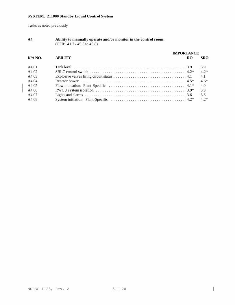
NUREG-1123, Rev. 2 |3.1-28
SYSTEM: 211000 Standby Liquid Control System
Tasks as noted previously
A4. Ability to manually operate and/or monitor in the control room:(CFR: 41.7 / 45.5 to 45.8)
IMPORTANCE K/A NO. ABILITY RO SRO
A4.01 Tank level . . . . . . . . . . . . . . . . . . . . . . . . . . . . . . . . . . . . . . . . . . . . . . . . . . . . . . . . . . . . . 3.9 3.9A4.02 SBLC control switch . . . . . . . . . . . . . . . . . . . . . . . . . . . . . . . . . . . . . . . . . . . . . . . . . . . . 4.2* 4.2*A4.03 Explosive valves firing circuit status . . . . . . . . . . . . . . . . . . . . . . . . . . . . . . . . . . . . . . . 4.1 4.1A4.04 Reactor power . . . . . . . . . . . . . . . . . . . . . . . . . . . . . . . . . . . . . . . . . . . . . . . . . . . . . . . . . 4.5* 4.6*A4.05 Flow indication: Plant-Specific . . . . . . . . . . . . . . . . . . . . . . . . . . . . . . . . . . . . . . . . . . 4.1* 4.0|A4.06 RWCU system isolation . . . . . . . . . . . . . . . . . . . . . . . . . . . . . . . . . . . . . . . . . . . . . . . . . 3.9* 3.9|A4.07 Lights and alarms . . . . . . . . . . . . . . . . . . . . . . . . . . . . . . . . . . . . . . . . . . . . . . . . . . . . . . . 3.6 3.6A4.08 System initiation: Plant-Specific . . . . . . . . . . . . . . . . . . . . . . . . . . . . . . . . . . . . . . . . . 4.2* 4.2*

NUREG-1123, Rev. 2 |3.1-29
This page left blank

NUREG-1123, Rev. 2 |3.2-1
3.2 Reactor Water Inventory Control page
206000 High Pressure Coolant Injection System 3.2-3209002 High Pressure Core Spray System 3.2-8209001 Low Pressure Core Spray System 3.2-12256000 Reactor Condensate System 3.2-16217000 Reactor Core Isolation Cooling System 3.2-21259001 Reactor Feedwater System 3.2-25204000 Reactor Water Cleanup System 3.2-29259002 Reactor Water Level Control System 3.2-33203000 Residual Heat Removal /Low Pressure Coolant Injection: 3.2-38
Injection Mode (Plant Specific)

NUREG-1123, Rev. 2 |3.2-2
This page left blank

NUREG-1123, Rev. 2 |3.2-3
SYSTEM: 206000 High Pressure Coolant Injection System
TASK: Place the high pressure (Feedwater) coolant injection system (FWCI) in standby readinessMonitor the high pressure (feedwater) coolant injection system operationReturn the high pressure (feedwater) coolant injection system to stand-by readiness after automaticinitiationPerform lineups of the high pressure coolant injection system (write in)Manually initiate high pressure coolant injectionPerform high pressure coolant injection (HPCI) simulated automatic actuation testPerform high pressure (feedwater) coolant injection flow rate testPerform high pressure (feedwater) coolant injection (HPCI) pump operability testPerform high pressure (feedwater) coolant injection motor operated valve operability testPerform HPCI subsystem logic system functional testPerform HPCI subsystem automatic isolation logic system functional testPerform HPCI system inoperable testPerform HPCI turbine overspeed testPerform high pressure (feedwater) coolant injection operability test when reactor core isolation coolingis inoperable
IMPORTANCE K/A NO. KNOWLEDGE RO SRO
K1. Knowledge of the physical connections and/or cause-effect relationships between HIGH PRESSURE COOLANTINJECTION SYSTEM and the following:(CFR: 41.2 to 41.9 / 45.7 to 45.8)
K1.01 Reactor vessel: BWR-2,3,4 . . . . . . . . . . . . . . . . . . . . . . . . . . . . . . . . . . . . . . . . . . . . . . 3.8 3.9K1.02 Reactor water level: BWR-2,3,4 . . . . . . . . . . . . . . . . . . . . . . . . . . . . . . . . . . . . . . . . . . 4.0 4.1* |K1.03 Reactor pressure: BWR-2,3,4 . . . . . . . . . . . . . . . . . . . . . . . . . . . . . . . . . . . . . . . . . . . . 3.8 3.8 |K1.04 Reactor feedwater system: BWR-2,3,4 . . . . . . . . . . . . . . . . . . . . . . . . . . . . . . . . . . . . 3.6 3.6K1.05 Condensate storage system: BWR-2,3,4 . . . . . . . . . . . . . . . . . . . . . . . . . . . . . . . . . . . 3.7 3.7 |K1.06 Suppression chamber: BWR-2,3,4 . . . . . . . . . . . . . . . . . . . . . . . . . . . . . . . . . . . . . . . . 3.7 3.7 |K1.07 D.C. power: BWR-2,3,4 . . . . . . . . . . . . . . . . . . . . . . . . . . . . . . . . . . . . . . . . . . . . . . . . . 3.7* 3.8* |K1.08 A.C. power: BWR-2,3,4 . . . . . . . . . . . . . . . . . . . . . . . . . . . . . . . . . . . . . . . . . . . . . . . . . 3.0* 3.1* |K1.09 ECCS keep fill system: BWR-2,3,4(P-Spec) . . . . . . . . . . . . . . . . . . . . . . . . . . . . . . . . 4.0* 4.0 |K1.10 Condensate storage and transfer system: BWR-2,3,4 . . . . . . . . . . . . . . . . . . . . . . . . . 3.4 3.4K1.11 PCIS: BWR-2,3,4 . . . . . . . . . . . . . . . . . . . . . . . . . . . . . . . . . . . . . . . . . . . . . . . . . . . . . . 3.5 3.5K1.12 Nuclear boiler instrumentation: BWR-2,3,4 . . . . . . . . . . . . . . . . . . . . . . . . . . . . . . . . 3.4 3.4 |K1.13 Main condenser: BWR-2,3,4(P-Spec) . . . . . . . . . . . . . . . . . . . . . . . . . . . . . . . . . . . . . 2.8* 2.9* |K1.14 SBGT: BWR-2,3,4(P-Spec) . . . . . . . . . . . . . . . . . . . . . . . . . . . . . . . . . . . . . . . . . . . . . . 2.9 3.1K1.15 Plant air systems: BWR-2,3,4 . . . . . . . . . . . . . . . . . . . . . . . . . . . . . . . . . . . . . . . . . . . . 2.3* 2.3* |K1.16 Containment/Torus pressure: BWR-2,3,4 . . . . . . . . . . . . . . . . . . . . . . . . . . . . . . . . . . 3.5 3.5 |

NUREG-1123, Rev. 2 |3.2-4
SYSTEM: 206000 High Pressure Coolant Injection System
IMPORTANCE K/A NO. KNOWLEDGE RO SRO
K2. Knowledge of electrical power supplies to thefollowing:(CFR: 41.7)
K2.01 System valves: BWR-2,3,4 . . . . . . . . . . . . . . . . . . . . . . . . . . . . . . . . . . . . . . . . . . . . . . 3.2* 3.3*K2.02 System pumps: BWR-2,3,4 . . . . . . . . . . . . . . . . . . . . . . . . . . . . . . . . . . . . . . . . . . . . . . 2.8* 3.1*K2.03 Initiation logic: BWR-2,3,4 . . . . . . . . . . . . . . . . . . . . . . . . . . . . . . . . . . . . . . . . . . . . . 2.8* 2.9*K2.04 Turbine control circuits: BWR-2,3,4 . . . . . . . . . . . . . . . . . . . . . . . . . . . . . . . . . . . . . . 2.5* 2.7*
K3. Knowledge of the effect that a loss or malfunction ofthe HIGH PRESSURE COOLANT INJECTION SYSTEM will haveon following:(CFR: 41.7 / 45.4)
K3.01 Reactor water level control: BWR-2,3,4 . . . . . . . . . . . . . . . . . . . . . . . . . . . . . . . . . . . 4.0 4.0K3.02 Reactor pressure control: BWR-2,3,4 . . . . . . . . . . . . . . . . . . . . . . . . . . . . . . . . . . . . . 3.8* 3.8*K3.03 Suppression pool level control: BWR-2,3,4 . . . . . . . . . . . . . . . . . . . . . . . . . . . . . . . . 3.4* 3.5*
K4. Knowledge of HIGH PRESSURE COOLANT INJECTION SYSTEMdesign feature(s) and/or interlocks which provide forthe following:(CFR: 41.7)
K4.01 Turbine trips: BWR-2,3,4 . . . . . . . . . . . . . . . . . . . . . . . . . . . . . . . . . . . . . . . . . . . . . . . 3.8 3.9K4.02 System isolation: BWR-2,3,4 . . . . . . . . . . . . . . . . . . . . . . . . . . . . . . . . . . . . . . . . . . . . 3.9 4.0K4.03 Resetting turbine trips: BWR-2,3,4 . . . . . . . . . . . . . . . . . . . . . . . . . . . . . . . . . . . . . . . 4.2 4.1K4.04 Resetting system isolations: BWR-2,3,4 . . . . . . . . . . . . . . . . . . . . . . . . . . . . . . . . . . . 4.0 3.9K4.05 Preventing water hammer in turbine exhaust line
(procedural control): BWR-2,3,4 . . . . . . . . . . . . . . . . . . . . . . . . . . . . . . . . . . . . . . . . . 3.1 3.4K4.06 Preventing water hammer in pump discharge line
(procedural control ): BWR-2, 3, 4 . . . . . . . . . . . . . . . . . . . . . . . . . . . . . . . . . . . . . . . 3.2 3.4K4.07 Automatic system initiation: BWR-2,3,4 . . . . . . . . . . . . . . . . . . . . . . . . . . . . . . . . . . 4.3* 4.3K4.08 Manual system initiation: BWR-2,3,4 . . . . . . . . . . . . . . . . . . . . . . . . . . . . . . . . . . . . . 4.2* 4.3K4.09 Automatic flow control: BWR-2,3,4 . . . . . . . . . . . . . . . . . . . . . . . . . . . . . . . . . . . . . . 3.8 3.9K4.10 Surveillance for all operable components: BWR-2,3,4 . . . . . . . . . . . . . . . . . . . . . . . . 3.7 3.8K4.11 Turbine speed control: BWR-2,3,4 . . . . . . . . . . . . . . . . . . . . . . . . . . . . . . . . . . . . . . . 3.4 3.5K4.12 Condensation of shaft sealing steam: BWR-2,3,4 . . . . . . . . . . . . . . . . . . . . . . . . . . . 2.9 3.0K4.13 Turbine and pump lubrication: BWR-2,3,4 . . . . . . . . . . . . . . . . . . . . . . . . . . . . . . . . . 3.0 3.1K4.14 Control oil to turbine speed controls: BWR-2,3,4 . . . . . . . . . . . . . . . . . . . . . . . . . . . 3.4 3.4K4.15 Low speed turning of the turbine rotor: BWR-2,3,4(P-
Spec) . . . . . . . . . . . . . . . . . . . . . . . . . . . . . . . . . . . . . . . . . . . . . . . . . . . . . . . . . . . . . . . . . 3.2 3.2K4.16 Minimizing fission product concentration in the
condensate storage tank (valve closures on systeminitiation): BWR-2,3,4(P-Spec) . . . . . . . . . . . . . . . . . . . . . . . . . . . . . . . . . . . . . . . . . . 3.1 3.3
K4.17 Protection against draining the condensate storagetank to the suppression pool: BWR-2,3,4 . . . . . . . . . . . . . . . . . . . . . . . . . . . . . . . . . . 3.4 3.4
K4.18 Pump minimum flow: BWR-2,3,4 . . . . . . . . . . . . . . . . . . . . . . . . . . . . . . . . . . . . . . . . 3.2 3.3K4.19 Automatic transfer of HPCI pump suction: BWR-2,3,4 . . . . . . . . . . . . . . . . . . . . . . . 3.7 3.8

NUREG-1123, Rev. 2 |3.2-5
SYSTEM: 206000 High Pressure Coolant Injection System
Tasks as noted previously IMPORTANCE K/A NO. KNOWLEDGE RO SRO
K5. Knowledge of the operational implications of thefollowing concepts as they apply to HIGH PRESSURECOOLANT INJECTION SYSTEM :(CFR: 41.5 / 45.3)
K5.01 Turbine operation: BWR-2,3,4 . . . . . . . . . . . . . . . . . . . . . . . . . . . . . . . . . . . . . . . . . . . 3.3 3.4K5.02 Turbine shaft sealing: BWR-2,3,4 . . . . . . . . . . . . . . . . . . . . . . . . . . . . . . . . . . . . . . . . . 2.8 2.9K5.03 GEMAC controllers: BWR-2,3,4(P-Spec) . . . . . . . . . . . . . . . . . . . . . . . . . . . . . . . . . . 3.1 3.1K5.04 Indications of pump cavitation: BWR-2,3,4 . . . . . . . . . . . . . . . . . . . . . . . . . . . . . . . . . 2.6* 2.7* |K5.05 Turbine speed control: BWR-2,3,4 . . . . . . . . . . . . . . . . . . . . . . . . . . . . . . . . . . . . . . . . 3.3 3.3K5.06 Turbine speed measurement: BWR-2,3,4 . . . . . . . . . . . . . . . . . . . . . . . . . . . . . . . . . . . 2.6* 2.6K5.07 System venting: BWR-2,3,4 . . . . . . . . . . . . . . . . . . . . . . . . . . . . . . . . . . . . . . . . . . . . . . 2.8 2.8K5.08 Vacuum breaker operation: BWR-2,3,4 . . . . . . . . . . . . . . . . . . . . . . . . . . . . . . . . . . . . 3.0 3.2K5.09 Testable check valve operation: BWR-2,3,4 . . . . . . . . . . . . . . . . . . . . . . . . . . . . . . . . . 2.7* 2.8K5.10 Assist core cooling: BWR-2,3,4 . . . . . . . . . . . . . . . . . . . . . . . . . . . . . . . . . . . . . . . . . . 3.5 3.5
K6. Knowledge of the effect that a loss or malfunction ofthe following will have on the HIGH PRESSURE COOLANTINJECTION SYSTEM :(CFR: 41.7 / 45.7)
K6.01 Plant air systems: BWR-2,3,4 . . . . . . . . . . . . . . . . . . . . . . . . . . . . . . . . . . . . . . . . . . . . 2.3* 2.3* |K6.02 D.C. power: BWR-2,3,4 . . . . . . . . . . . . . . . . . . . . . . . . . . . . . . . . . . . . . . . . . . . . . . . . . 3.3 3.7* |K6.03 A.C. power: BWR-2,3,4 . . . . . . . . . . . . . . . . . . . . . . . . . . . . . . . . . . . . . . . . . . . . . . . . . 2.9 3.1* |K6.04 Condensate storage tank level: BWR-2,3,4 . . . . . . . . . . . . . . . . . . . . . . . . . . . . . . . . . 3.5 3.7K6.05 Suppression pool level: BWR-2,3,4 . . . . . . . . . . . . . . . . . . . . . . . . . . . . . . . . . . . . . . . 3.5 3.7K6.06 SBGTS: BWR-2,3,4(P-Spec) . . . . . . . . . . . . . . . . . . . . . . . . . . . . . . . . . . . . . . . . . . . . . 3.1 3.2K6.07 ECCS keep fill system: BWR-2,3,4(P-Spec) . . . . . . . . . . . . . . . . . . . . . . . . . . . . . . . . 3.4 3.4K6.08 Reactor pressure: BWR-2,3,4 . . . . . . . . . . . . . . . . . . . . . . . . . . . . . . . . . . . . . . . . . . . . 3.8 3.8K6.09 Condensate storage and transfer system: BWR-2,3,4 . . . . . . . . . . . . . . . . . . . . . . . . . 3.5 3.5K6.10 PCIS: BWR-2,3,4 . . . . . . . . . . . . . . . . . . . . . . . . . . . . . . . . . . . . . . . . . . . . . . . . . . . . . . 3.8 4.0K6.11 Nuclear boiler instrumentation: BWR-2,3,4 . . . . . . . . . . . . . . . . . . . . . . . . . . . . . . . . 3.6 3.7K6.12 Reactor water level: BWR-2,3,4 . . . . . . . . . . . . . . . . . . . . . . . . . . . . . . . . . . . . . . . . . . 4.2* 4.3* |
ABILITY
A1. Ability to predict and/or monitor changes inparameters associated with operating the HIGH PRESSURECOOLANT INJECTION SYSTEM controls including:(CFR: 41.5 / 45.5)
A1.01 Reactor water level: BWR-2,3,4 . . . . . . . . . . . . . . . . . . . . . . . . . . . . . . . . . . . . . . . . . . 4.3* 4.4* |A1.02 Reactor pressure: BWR-2,3,4 . . . . . . . . . . . . . . . . . . . . . . . . . . . . . . . . . . . . . . . . . . . . 4.2* 4.2A1.03 Condensate storage tank level: BWR-2,3,4 . . . . . . . . . . . . . . . . . . . . . . . . . . . . . . . . . 3.5 3.6A1.04 Suppression pool level: BWR-2,3,4 . . . . . . . . . . . . . . . . . . . . . . . . . . . . . . . . . . . . . . . 3.7 3.8A1.05 Suppression pool temperature: BWR-2,3,4 . . . . . . . . . . . . . . . . . . . . . . . . . . . . . . . . . 4.1 4.2A1.06 System flow: BWR-2,3,4 . . . . . . . . . . . . . . . . . . . . . . . . . . . . . . . . . . . . . . . . . . . . . . . . 3.8 3.7A1.07 System discharge pressure: BWR-2,3,4 . . . . . . . . . . . . . . . . . . . . . . . . . . . . . . . . . . . . 3.7 3.6A1.08 System lineup: BWR-2,3,4 . . . . . . . . . . . . . . . . . . . . . . . . . . . . . . . . . . . . . . . . . . . . . . . 4.1* 4.0

NUREG-1123, Rev. 2 |3.2-6
SYSTEM: 206000 High Pressure Coolant Injection System
Tasks as noted previously
IMPORTANCE K/A NO. KNOWLEDGE RO SRO
A1.09 Turbine speed: BWR-2,3,4 . . . . . . . . . . . . . . . . . . . . . . . . . . . . . . . . . . . . . . . . . . . . . . 3.5 3.4
A2. Ability to (a) predict the impacts of the following onthe HIGH PRESSURE COOLANT INJECTION SYSTEM ; and (b)based on those predictions, use procedures to correct,control, or mitigate the consequences of thoseabnormal conditions or operations:(CFR: 41.5 / 45.6)
A2.01 Turbine trips: BWR-2,3,4 . . . . . . . . . . . . . . . . . . . . . . . . . . . . . . . . . . . . . . . . . . . . . . . . 4.0 4.0A2.02 Valve closures: BWR-2,3,4 . . . . . . . . . . . . . . . . . . . . . . . . . . . . . . . . . . . . . . . . . . . . . . 3.5 3.5A2.03 Valve openings: BWR-2,3,4 . . . . . . . . . . . . . . . . . . . . . . . . . . . . . . . . . . . . . . . . . . . . . . 3.5 3.5A2.04 A.C. failures: BWR-2,3,4 . . . . . . . . . . . . . . . . . . . . . . . . . . . . . . . . . . . . . . . . . . . . . . . . 2.7* 3.0*A2.05 D.C. failures: BWR-2,3,4 . . . . . . . . . . . . . . . . . . . . . . . . . . . . . . . . . . . . . . . . . . . . . . . . 3.5 3.8*A2.06 Inadequate system flow: BWR-2,3,4 . . . . . . . . . . . . . . . . . . . . . . . . . . . . . . . . . . . . . . . 3.3 3.5A2.07 Low suppression pool level: BWR-2,3,4 . . . . . . . . . . . . . . . . . . . . . . . . . . . . . . . . . . . 3.4 3.6A2.08 †High suppression pool temperature: BWR-2,3,4 . . . . . . . . . . . . . . . . . . . . . . . . . . . . 3.9 4.2A2.09 †Low condensate storage tank level: BWR-2,3,4 . . . . . . . . . . . . . . . . . . . . . . . . . . . . 3.5 3.7A2.10 System isolation: BWR-2,3,4 . . . . . . . . . . . . . . . . . . . . . . . . . . . . . . . . . . . . . . . . . . . . 4.0 4.1A2.11 Low reactor water level: BWR-2,3,4 . . . . . . . . . . . . . . . . . . . . . . . . . . . . . . . . . . . . . . 4.1 4.2A2.12 Loss of room cooling: BWR-2,3,4 . . . . . . . . . . . . . . . . . . . . . . . . . . . . . . . . . . . . . . . . 3.4 3.5A2.13 Loss of applicable plant air systems: BWR-2,3,4 . . . . . . . . . . . . . . . . . . . . . . . . . . . . 2.4* 2.4*A2.14 Flow controller failure: BWR-2,3,4 . . . . . . . . . . . . . . . . . . . . . . . . . . . . . . . . . . . . . . . 3.3 3.4A2.15 Loss of control oil pressure: BWR-2,3,4 . . . . . . . . . . . . . . . . . . . . . . . . . . . . . . . . . . . 3.4 3.5A2.16 High drywell pressure: BWR-2,3,4 . . . . . . . . . . . . . . . . . . . . . . . . . . . . . . . . . . . . . . . . 4.0 4.1A2.17 †HPCI inadvertent initiation: BWR-2,3,4 . . . . . . . . . . . . . . . . . . . . . . . . . . . . . . . . . . . 3.9 4.3*
A3. Ability to monitor automatic operations of the HIGHPRESSURE COOLANT INJECTION SYSTEM including:(CFR: 41.7 / 45.7)
A3.01 Turbine speed: BWR-2,3,4 . . . . . . . . . . . . . . . . . . . . . . . . . . . . . . . . . . . . . . . . . . . . . . . 3.6 3.5A3.02 System Flow: BWR-2,3,4 . . . . . . . . . . . . . . . . . . . . . . . . . . . . . . . . . . . . . . . . . . . . . . . . 3.8 3.8A3.03 System lineup: BWR-2,3,4 . . . . . . . . . . . . . . . . . . . . . . . . . . . . . . . . . . . . . . . . . . . . . . . 3.9 3.8A3.04 Reactor pressure: BWR-2,3,4 . . . . . . . . . . . . . . . . . . . . . . . . . . . . . . . . . . . . . . . . . . . . 4.2* 4.1A3.05 Reactor water level: BWR-2,3,4 . . . . . . . . . . . . . . . . . . . . . . . . . . . . . . . . . . . . . . . . . . 4.3* 4.3*|A3.06 System discharge pressure: BWR-2,3,4 . . . . . . . . . . . . . . . . . . . . . . . . . . . . . . . . . . . . 3.8 3.8A3.07 Lights and alarms: BWR-2,3,4 . . . . . . . . . . . . . . . . . . . . . . . . . . . . . . . . . . . . . . . . . . . . 3.9 3.8A3.08 Condensate storage tank level: BWR-2,3,4 . . . . . . . . . . . . . . . . . . . . . . . . . . . . . . . . . 3.7 3.6A3.09 Response to system isolation: BWR-2,3,4 . . . . . . . . . . . . . . . . . . . . . . . . . . . . . . . . . . 4.2* 4.1
A4. Ability to manually operate and/or monitor in thecontrol room:(CFR: 41.7 / 45.5 to 45.8)
A4.01 Turbine speed controls: BWR-2,3,4 . . . . . . . . . . . . . . . . . . . . . . . . . . . . . . . . . . . . . . . 3.8 3.7A4.02 Flow controller: BWR-2,3,4 . . . . . . . . . . . . . . . . . . . . . . . . . . . . . . . . . . . . . . . . . . . . . 4.0* 3.8

NUREG-1123, Rev. 2 |3.2-7
SYSTEM: 206000 High Pressure Coolant Injection System
Tasks as noted previously
IMPORTANCE K/A NO. KNOWLEDGE RO SRO
A4.03 Turbine temperatures: BWR-2,3,4 . . . . . . . . . . . . . . . . . . . . . . . . . . . . . . . . . . . . . . . . 3.1 3.0A4.04 Major system valves: BWR-2,3.4 . . . . . . . . . . . . . . . . . . . . . . . . . . . . . . . . . . . . . . . . . 3.7 3.7A4.05 Reactor water level: BWR-2,3,4 . . . . . . . . . . . . . . . . . . . . . . . . . . . . . . . . . . . . . . . . . . 4.4* 4.4*A4.06 Reactor pressure: BWR-2,3,4 . . . . . . . . . . . . . . . . . . . . . . . . . . . . . . . . . . . . . . . . . . . . 4.3* 4.3*A4.07 Condensate storage tank level: BWR-2,3,4 . . . . . . . . . . . . . . . . . . . . . . . . . . . . . . . . . 3.5 3.5A4.08 Suppression pool temperature: BWR-2,3,4 . . . . . . . . . . . . . . . . . . . . . . . . . . . . . . . . . 4.1* 4.1A4.09 Suppression pool level: BWR-2,3,4 . . . . . . . . . . . . . . . . . . . . . . . . . . . . . . . . . . . . . . . 3.8 3.7A4.10 System pumps: BWR-2,3,4 . . . . . . . . . . . . . . . . . . . . . . . . . . . . . . . . . . . . . . . . . . . . . . 3.7 3.5A4.11 Turning gear: BWR-2,3,4(P-Spec) . . . . . . . . . . . . . . . . . . . . . . . . . . . . . . . . . . . . . . . . 3.0 3.0A4.12 Turbine trip controls: BWR-2,3,4 . . . . . . . . . . . . . . . . . . . . . . . . . . . . . . . . . . . . . . . . . 4.0 3.9A4.13 Turbine reset control: BWR-2,3,4 . . . . . . . . . . . . . . . . . . . . . . . . . . . . . . . . . . . . . . . . . 4.1* 4.0A4.14 System auto start control: BWR-2,3,4(P-Spec) . . . . . . . . . . . . . . . . . . . . . . . . . . . . . . 4.2* 4.1
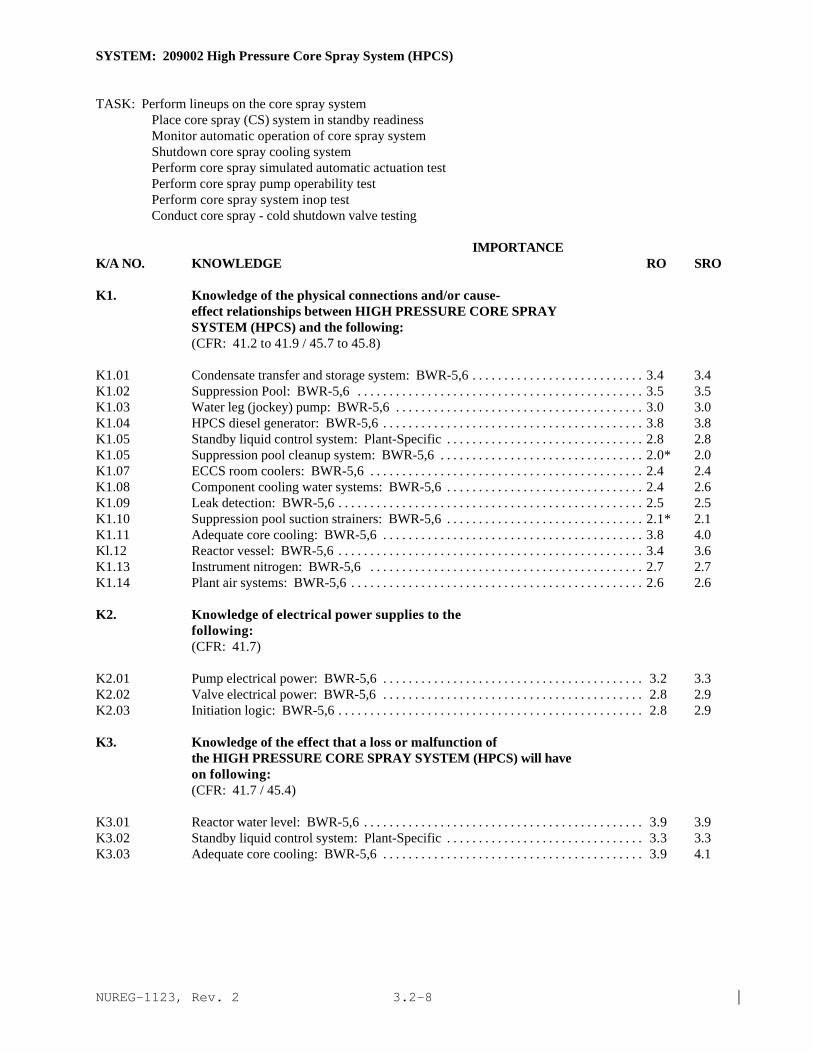
NUREG-1123, Rev. 2 |3.2-8
SYSTEM: 209002 High Pressure Core Spray System (HPCS)
TASK: Perform lineups on the core spray systemPlace core spray (CS) system in standby readinessMonitor automatic operation of core spray systemShutdown core spray cooling systemPerform core spray simulated automatic actuation testPerform core spray pump operability testPerform core spray system inop testConduct core spray - cold shutdown valve testing
IMPORTANCE K/A NO. KNOWLEDGE RO SRO
K1. Knowledge of the physical connections and/or cause-effect relationships between HIGH PRESSURE CORE SPRAYSYSTEM (HPCS) and the following:(CFR: 41.2 to 41.9 / 45.7 to 45.8)
K1.01 Condensate transfer and storage system: BWR-5,6 . . . . . . . . . . . . . . . . . . . . . . . . . . . 3.4 3.4K1.02 Suppression Pool: BWR-5,6 . . . . . . . . . . . . . . . . . . . . . . . . . . . . . . . . . . . . . . . . . . . . . 3.5 3.5K1.03 Water leg (jockey) pump: BWR-5,6 . . . . . . . . . . . . . . . . . . . . . . . . . . . . . . . . . . . . . . . 3.0 3.0K1.04 HPCS diesel generator: BWR-5,6 . . . . . . . . . . . . . . . . . . . . . . . . . . . . . . . . . . . . . . . . . 3.8 3.8K1.05 Standby liquid control system: Plant-Specific . . . . . . . . . . . . . . . . . . . . . . . . . . . . . . . 2.8 2.8K1.05 Suppression pool cleanup system: BWR-5,6 . . . . . . . . . . . . . . . . . . . . . . . . . . . . . . . . 2.0* 2.0K1.07 ECCS room coolers: BWR-5,6 . . . . . . . . . . . . . . . . . . . . . . . . . . . . . . . . . . . . . . . . . . . 2.4 2.4K1.08 Component cooling water systems: BWR-5,6 . . . . . . . . . . . . . . . . . . . . . . . . . . . . . . . 2.4 2.6K1.09 Leak detection: BWR-5,6 . . . . . . . . . . . . . . . . . . . . . . . . . . . . . . . . . . . . . . . . . . . . . . . . 2.5 2.5K1.10 Suppression pool suction strainers: BWR-5,6 . . . . . . . . . . . . . . . . . . . . . . . . . . . . . . . 2.1* 2.1K1.11 Adequate core cooling: BWR-5,6 . . . . . . . . . . . . . . . . . . . . . . . . . . . . . . . . . . . . . . . . . 3.8 4.0Kl.12 Reactor vessel: BWR-5,6 . . . . . . . . . . . . . . . . . . . . . . . . . . . . . . . . . . . . . . . . . . . . . . . . 3.4 3.6K1.13 Instrument nitrogen: BWR-5,6 . . . . . . . . . . . . . . . . . . . . . . . . . . . . . . . . . . . . . . . . . . . 2.7 2.7K1.14 Plant air systems: BWR-5,6 . . . . . . . . . . . . . . . . . . . . . . . . . . . . . . . . . . . . . . . . . . . . . . 2.6 2.6
K2. Knowledge of electrical power supplies to thefollowing:(CFR: 41.7)
K2.01 Pump electrical power: BWR-5,6 . . . . . . . . . . . . . . . . . . . . . . . . . . . . . . . . . . . . . . . . . 3.2 3.3K2.02 Valve electrical power: BWR-5,6 . . . . . . . . . . . . . . . . . . . . . . . . . . . . . . . . . . . . . . . . . 2.8 2.9K2.03 Initiation logic: BWR-5,6 . . . . . . . . . . . . . . . . . . . . . . . . . . . . . . . . . . . . . . . . . . . . . . . . 2.8 2.9
K3. Knowledge of the effect that a loss or malfunction ofthe HIGH PRESSURE CORE SPRAY SYSTEM (HPCS) will haveon following:(CFR: 41.7 / 45.4)
K3.01 Reactor water level: BWR-5,6 . . . . . . . . . . . . . . . . . . . . . . . . . . . . . . . . . . . . . . . . . . . . 3.9 3.9K3.02 Standby liquid control system: Plant-Specific . . . . . . . . . . . . . . . . . . . . . . . . . . . . . . . 3.3 3.3K3.03 Adequate core cooling: BWR-5,6 . . . . . . . . . . . . . . . . . . . . . . . . . . . . . . . . . . . . . . . . . 3.9 4.1

NUREG-1123, Rev. 2 |3.2-9
SYSTEM: 209002 High Pressure Core Spray System (HPCS)
IMPORTANCE K/A NO. KNOWLEDGE RO SRO
K4. Knowledge of HIGH PRESSURE CORE SPRAY SYSTEM (HPCS)design feature(s) and/or interlocks which provide forthe following:(CFR: 41.7)
K4.01 Prevents water hammer: BWR-5,6 . . . . . . . . . . . . . . . . . . . . . . . . . . . . . . . . . . . . . . . . 2.9 3.0K4.02 Prevents over filling reactor vessel: Plant-Specific. . . . . . . . . . . . . . . . . . . . . . . . . . . 3.4 3.5K4.03 Prevents pump over heating: BWR-5,6 . . . . . . . . . . . . . . . . . . . . . . . . . . . . . . . . . . . . . 2.3* 2.4K4.04 Testable check valve operation: BWR-5,6 . . . . . . . . . . . . . . . . . . . . . . . . . . . . . . . . . . 2.3* 2.3*K4.05 Motor operated valve operation: BWR-5,6 . . . . . . . . . . . . . . . . . . . . . . . . . . . . . . . . . 2.4 2.4K4.06 Centrifugal pump operation: BWR-5,6 . . . . . . . . . . . . . . . . . . . . . . . . . . . . . . . . . . . . . 2.3* 2.4*K4.07 Override of reactor water level interlock: Plant-
Specific . . . . . . . . . . . . . . . . . . . . . . . . . . . . . . . . . . . . . . . . . . . . . . . . . . . . . . . . . . . . . . . 3.5 3.7
K5. Knowledge of the operational implications of thefollowing concepts as they apply to HIGH PRESSURE CORESPRAY SYSTEM (HPCS):(CFR: 41.5 / 45.3)
K5.01 Indications of pump cavitation: BWR-5,6 . . . . . . . . . . . . . . . . . . . . . . . . . . . . . . . . . . . 2.5 2.8K5.02 Heat removal (transfer) mechanism: BWR-5,6 . . . . . . . . . . . . . . . . . . . . . . . . . . . . . . 2.6 2.7K5.03 System venting: BWR-5,6 . . . . . . . . . . . . . . . . . . . . . . . . . . . . . . . . . . . . . . . . . . . . . . . 2.4 2.4K5.04 Adequate core cooling: BWR-5,6 . . . . . . . . . . . . . . . . . . . . . . . . . . . . . . . . . . . . . . . . . 3.8 4.0
K6. Knowledge of the effect that a loss or malfunction ofthe following will have on the HIGH PRESSURE CORESPRAY SYSTEM (HPCS):(CFR: 41.7 / 45.7)
K6.01 Electrical power: BWR-5,6 . . . . . . . . . . . . . . . . . . . . . . . . . . . . . . . . . . . . . . . . . . . . . . 3.6 3.6K6.02 Condensate storage tank water level: BWR-5,6 . . . . . . . . . . . . . . . . . . . . . . . . . . . . . . 3.4 3.4K6.03 Component cooling water systems: BWR-5,6 . . . . . . . . . . . . . . . . . . . . . . . . . . . . . . . 2.5 2.6K6.04 Suppression pool suction strainer: BWR-5,6 . . . . . . . . . . . . . . . . . . . . . . . . . . . . . . . . 2.5 2.5
ABILITY
A1. Ability to predict and/or monitor changes inparameters associated with operating the HIGH PRESSURECORE SPRAY SYSTEM (HPCS) controls including:(CFR: 41.5 / 45.5)
A1.01 HPCS flow: BWR-5,6 . . . . . . . . . . . . . . . . . . . . . . . . . . . . . . . . . . . . . . . . . . . . . . . . . . . 3.6 3.7A1.02 HPCS pressure: BWR-5,6 . . . . . . . . . . . . . . . . . . . . . . . . . . . . . . . . . . . . . . . . . . . . . . . 3.4 3.6A1.03 Reactor water level: BWR-5,6 . . . . . . . . . . . . . . . . . . . . . . . . . . . . . . . . . . . . . . . . . . . . 3.7 3.7A1.04 Reactor pressure: BWR-5,6 . . . . . . . . . . . . . . . . . . . . . . . . . . . . . . . . . . . . . . . . . . . . . . 3.3 3.3A1.05 Suppression pool water level: BWR-5,6 . . . . . . . . . . . . . . . . . . . . . . . . . . . . . . . . . . . . 3.3 3.4A1.06 Motor amps: BWR-5,6 . . . . . . . . . . . . . . . . . . . . . . . . . . . . . . . . . . . . . . . . . . . . . . . . . . 1.9* 2.3*A1.07 Diesel loading: BWR-5,6 . . . . . . . . . . . . . . . . . . . . . . . . . . . . . . . . . . . . . . . . . . . . . . . . 2.5* 2.8A1.08 System lineup: BWR-5,6 . . . . . . . . . . . . . . . . . . . . . . . . . . . . . . . . . . . . . . . . . . . . . . . . 3.1 3.3

NUREG-1123, Rev. 2 |3.2-10
SYSTEM: 209002 High Pressure Core Spray System (HPCS)
Tasks as noted previously
IMPORTANCE K/A NO. KNOWLEDGE RO SRO
A1.09 Condensate storage tank level: BWR-5,6 2.6 2.8
A2. Ability to (a) predict the impacts of the following onthe HIGH PRESSURE CORE SPRAY SYSTEM (HPCS) ; and (b)based on those predictions, use procedures to correct,control, or mitigate the consequences of thoseabnormal conditions or operations:(CFR: 41.5 / 45.6)
A2.01 System initiation: BWR-5,6 . . . . . . . . . . . . . . . . . . . . . . . . . . . . . . . . . . . . . . . . . . . . . . . 3.8 3.8A2.02 Pump trips: BWR-5,6 . . . . . . . . . . . . . . . . . . . . . . . . . . . . . . . . . . . . . . . . . . . . . . . . . . . . 3.6 3.7A2.03 Valve closures: BWR-5,6 . . . . . . . . . . . . . . . . . . . . . . . . . . . . . . . . . . . . . . . . . . . . . . . . . 3.2 3.4A2.04 A.C. electrical failure: BWR-5,6 . . . . . . . . . . . . . . . . . . . . . . . . . . . . . . . . . . . . . . . . . . . 3.1 3.2A2.05 D.C. electrical failure: BWR-5,6 . . . . . . . . . . . . . . . . . . . . . . . . . . . . . . . . . . . . . . . . . . . 2.8 2.9A2.06 Core spray line break: BWR-5,6 . . . . . . . . . . . . . . . . . . . . . . . . . . . . . . . . . . . . . . . . . . . 3.4 3.6A2.07 Pump seal failure: BWR-5,6 . . . . . . . . . . . . . . . . . . . . . . . . . . . . . . . . . . . . . . . . . . . . . . 2.6 3.0A2.08 Inadequate system flow: BWR-5,6 . . . . . . . . . . . . . . . . . . . . . . . . . . . . . . . . . . . . . . . . . 3.1 3.2A2.09 Loss of room cooling: BWR-5,6 . . . . . . . . . . . . . . . . . . . . . . . . . . . . . . . . . . . . . . . . . . . 2.4 2.6A2.10 Valve openings: BWR-5,6 . . . . . . . . . . . . . . . . . . . . . . . . . . . . . . . . . . . . . . . . . . . . . . . . 2.7 3.0A2.11 Low suppression pool level: BWR-5,6 . . . . . . . . . . . . . . . . . . . . . . . . . . . . . . . . . . . . . 3.3 3.5A2.12 High suppression pool level BWR-5,6 . . . . . . . . . . . . . . . . . . . . . . . . . . . . . . . . . . . . . . . 3.3 3.5A2.13 Low condensate storage tank level BWR-5,6 . . . . . . . . . . . . . . . . . . . . . . . . . . . . . . . . . 3.4 3.5A2.14 High suppression pool temperature: BWR-5,6 . . . . . . . . . . . . . . . . . . . . . . . . . . . . . . . 3.0 3.3A2.15 Clogged suppression pool suction strainers: BWR-5,6. . . . . . . . . . . . . . . . . . . . . . . . . 2.4 2.6
A3. Ability to monitor automatic operations of the HIGHPRESSURE CORE SPRAY SYSTEM (HPCS) including:(CFR: 41.7 / 45.7)
A3.01 Valve operation: BWR-5,6 . . . . . . . . . . . . . . . . . . . . . . . . . . . . . . . . . . . . . . . . . . . . . . . . 3.3 3.3A3.02 Pump start: BWR-5,6 . . . . . . . . . . . . . . . . . . . . . . . . . . . . . . . . . . . . . . . . . . . . . . . . . . . . 3.8 3.8A3.03 System pressure: BWR-5,6 . . . . . . . . . . . . . . . . . . . . . . . . . . . . . . . . . . . . . . . . . . . . . . . 3.6 3.6A3.04 System flow: BWR-5,6 . . . . . . . . . . . . . . . . . . . . . . . . . . . . . . . . . . . . . . . . . . . . . . . . . . . 3.7 3.7A3.05 Reactor water level BWR-5,6 . . . . . . . . . . . . . . . . . . . . . . . . . . . . . . . . . . . . . . . . . . . . . . 3.7 3.7A3.06 Lights and alarms: BWR-5,6 . . . . . . . . . . . . . . . . . . . . . . . . . . . . . . . . . . . . . . . . . . . . . . 2.8 2.8
A4. Ability to manually operate and/or monitor in thecontrol room:(CFR: 41.7 / 45.5 to 45.8)
A4.01 HPCS pump: BWR-5,6 . . . . . . . . . . . . . . . . . . . . . . . . . . . . . . . . . . . . . . . . . . . . . . . . . . . 3.7 3.7A4.02 Suction valves: BWR-5,6 . . . . . . . . . . . . . . . . . . . . . . . . . . . . . . . . . . . . . . . . . . . . . . . . . 3.6 3.6A4.03 Injection valve: BWR-5,6 . . . . . . . . . . . . . . . . . . . . . . . . . . . . . . . . . . . . . . . . . . . . . . . . . 3.8 3.8A4.04 Minimum flow valve: BWR-5,6 . . . . . . . . . . . . . . . . . . . . . . . . . . . . . . . . . . . . . . . . . . . . 3.1 3.1A4.05 Manual Initiation controls: BWR-5,6 . . . . . . . . . . . . . . . . . . . . . . . . . . . . . . . . . . . . . . . 3.8 3.8

NUREG-1123, Rev. 2 |3.2-11
SYSTEM: 209002 High Pressure Core Spray System (HPCS)
Tasks as noted previously
IMPORTANCE K/A NO. KNOWLEDGE RO SRO
A4.06 Testable check valve: BWR-5,6 2.6 2.6A4.07 Line fill pump: BWR-5,6 2.8 2.8A4.08 Reactor water level: BWR-5,6 3.6 3.7A4.09 Suppression pool level: BWR-5,6 3.4 3.5A4.10 Reactor pressure: BWR-5,6 3.3 3.3A4.11 System flow: BWR-5,6 3.8 3.8A4.12 System pressure: BWR-5,6 . . . . . . . . . . . . . . . . . . . . . . . . . . . . . . . . . . . . . . . . . . . . . . . 3.4 3.4A4.13 Lights and alarms: BWR-5,6 . . . . . . . . . . . . . . . . . . . . . . . . . . . . . . . . . . . . . . . . . . . . . . 2.6 2.6A4.14 Test return valve: BWR-5,6 . . . . . . . . . . . . . . . . . . . . . . . . . . . . . . . . . . . . . . . . . . . . . . . 3.0 3.0A4.15 Initiation reset: BWR-5,6 . . . . . . . . . . . . . . . . . . . . . . . . . . . . . . . . . . . . . . . . . . . . . . . . . 3.6 3.6

NUREG-1123, Rev. 2 |3.2-12
SYSTEM: 209001 Low Pressure Core Spray System
TASK: Fill the core spray systemsPerform lineups on the core spray systemsPlace the core spray system in standby readinessMonitor automatic operation of the core spray systemShutdown the core spray cooling systemFill the reactor cavity from the condensate storage tank with the core spray systemPerform core spray pump flow rate testPerform core spray simulated automatic actuation testPerform core spray pump operability testPerform core spray subsys and low pressure coolant injection subsys discharge piping ventilationPerform core spray system inop testConduct core spray motor operated valve operability test
IMPORTANCE K/A NO. KNOWLEDGE RO SRO
K1. Knowledge of the physical connections and/or cause-effect relationships between LOW PRESSURE CORE SPRAYSYSTEM and the following:(CFR: 41.2 to 41.9 / 45.7 to 45.8)
K1.01 Condensate storage tank: Plant-Specific . . . . . . . . . . . . . . . . . . . . . . . . . . . . . . . . . . . 3.1 3.1K1.02 Torus/suppression pool . . . . . . . . . . . . . . . . . . . . . . . . . . . . . . . . . . . . . . . . . . . . . . . . . . 3.4 3.4K1.03 Keep fill system . . . . . . . . . . . . . . . . . . . . . . . . . . . . . . . . . . . . . . . . . . . . . . . . . . . . . . . 2.9 3.0K1.04 condensate transfer system . . . . . . . . . . . . . . . . . . . . . . . . . . . . . . . . . . . . . . . . . . . . . . 2.3 2.4K1.05 Automatic depressurization system . . . . . . . . . . . . . . . . . . . . . . . . . . . . . . . . . . . . . . . . 3.7 3.7K1.06 Plant air systems . . . . . . . . . . . . . . . . . . . . . . . . . . . . . . . . . . . . . . . . . . . . . . . . . . . . . . . 2.0* 2.1*K1.07 D.C. electrical power . . . . . . . . . . . . . . . . . . . . . . . . . . . . . . . . . . . . . . . . . . . . . . . . . . . 2.5 2.7K1.08 A.C. electrical power . . . . . . . . . . . . . . . . . . . . . . . . . . . . . . . . . . . . . . . . . . . . . . . . . . . 3.2 3.3K1.09 Nuclear boiler instrumentation . . . . . . . . . . . . . . . . . . . . . . . . . . . . . . . . . . . . . . . . . . . 3.2 3.4K1.10 Emergency generator . . . . . . . . . . . . . . . . . . . . . . . . . . . . . . . . . . . . . . . . . . . . . . . . . . . 3.7 3.8K1.11 Drywell coolers: Plant-Specific . . . . . . . . . . . . . . . . . . . . . . . . . . . . . . . . . . . . . . . . . . 2.4 2.6K1.12 ECCS room coolers . . . . . . . . . . . . . . . . . . . . . . . . . . . . . . . . . . . . . . . . . . . . . . . . . . . . 2.9 3.1K1.13 Leak detection . . . . . . . . . . . . . . . . . . . . . . . . . . . . . . . . . . . . . . . . . . . . . . . . . . . . . . . . . 2.8 3.0K1.14 Reactor vessel . . . . . . . . . . . . . . . . . . . . . . . . . . . . . . . . . . . . . . . . . . . . . . . . . . . . . . . . . 3.7 3.8
K2. Knowledge of electrical power supplies to thefollowing:(CFR: 41.7)
K2.01 Pump power . . . . . . . . . . . . . . . . . . . . . . . . . . . . . . . . . . . . . . . . . . . . . . . . . . . . . . . . . . . 3.0* 3.1*K2.02 Valve power . . . . . . . . . . . . . . . . . . . . . . . . . . . . . . . . . . . . . . . . . . . . . . . . . . . . . . . . . . . 2.5* 2.7*K2.03 Initiation logic . . . . . . . . . . . . . . . . . . . . . . . . . . . . . . . . . . . . . . . . . . . . . . . . . . . . . . . . . 2.9* 3.1*

NUREG-1123, Rev. 2 |3.2-13
SYSTEM: 209001 Low Pressure Core Spray System
Tasks as noted previously
IMPORTANCE K/A NO. KNOWLEDGE RO SRO
K3. Knowledge of the effect that a loss or malfunction ofthe LOW PRESSURE CORE SPRAY SYSTEM will have onfollowing:(CFR: 41.7 / 45.4)
K3.01 Reactor water level . . . . . . . . . . . . . . . . . . . . . . . . . . . . . . . . . . . . . . . . . . . . . . . . . . . . . 3.8 3.9 |K3.02 ADS logic . . . . . . . . . . . . . . . . . . . . . . . . . . . . . . . . . . . . . . . . . . . . . . . . . . . . . . . . . . . . . 3.8 3.9K3.03 Emergency generators . . . . . . . . . . . . . . . . . . . . . . . . . . . . . . . . . . . . . . . . . . . . . . . . . . 2.9 3.0K3.04 Component cooling water systems . . . . . . . . . . . . . . . . . . . . . . . . . . . . . . . . . . . . . . . . 2.1* 2.2K3.05 Drywell cooling: Plant-Specific . . . . . . . . . . . . . . . . . . . . . . . . . . . . . . . . . . . . . . . . . . 2.3 2.7
K4. Knowledge of LOW PRESSURE CORE SPRAY SYSTEM designfeature(s) and/or interlocks which provide for thefollowing:(CFR: 41.7)
K4.01 Prevention of overpressurization of core spray piping . . . . . . . . . . . . . . . . . . . . . . . . . 3.2 3.4K4.02 Prevents water hammer . . . . . . . . . . . . . . . . . . . . . . . . . . . . . . . . . . . . . . . . . . . . . . . . . . 3.0 3.2K4.03 Motor cooling . . . . . . . . . . . . . . . . . . . . . . . . . . . . . . . . . . . . . . . . . . . . . . . . . . . . . . . . . 2.4 2.5K4.04 Line break detection . . . . . . . . . . . . . . . . . . . . . . . . . . . . . . . . . . . . . . . . . . . . . . . . . . . . 3.0 3.2K4.05 Pump minimum flow . . . . . . . . . . . . . . . . . . . . . . . . . . . . . . . . . . . . . . . . . . . . . . . . . . . . 2.6 2.6K4.06 Adequate pump net positive suction head . . . . . . . . . . . . . . . . . . . . . . . . . . . . . . . . . . . 2.6 2.9K4.07 Pump operability testing . . . . . . . . . . . . . . . . . . . . . . . . . . . . . . . . . . . . . . . . . . . . . . . . . 2.8 3.0K4.08 Automatic system initiation . . . . . . . . . . . . . . . . . . . . . . . . . . . . . . . . . . . . . . . . . . . . . . 3.8 4.0K4.09 Load sequencing . . . . . . . . . . . . . . . . . . . . . . . . . . . . . . . . . . . . . . . . . . . . . . . . . . . . . . . 3.3 3.5K4.10 Testability of all operable components . . . . . . . . . . . . . . . . . . . . . . . . . . . . . . . . . . . . . 2.8 2.9
K5. Knowledge of the operational implications of thefollowing concepts as they apply to LOW PRESSURE CORESPRAY SYSTEM :(CFR: 41.5 / 45.3)
K5.01 Indications of pump cavitation . . . . . . . . . . . . . . . . . . . . . . . . . . . . . . . . . . . . . . . . . . . . 2.6 2.7K5.02 Differential pressure indication . . . . . . . . . . . . . . . . . . . . . . . . . . . . . . . . . . . . . . . . . . . 2.4 2.6K5.03 Testable check valve operation . . . . . . . . . . . . . . . . . . . . . . . . . . . . . . . . . . . . . . . . . . . . 2.3 2.4K5.04 Heat removal (transfer) mechanisms . . . . . . . . . . . . . . . . . . . . . . . . . . . . . . . . . . . . . . . 2.8 2.9K5.05 System venting . . . . . . . . . . . . . . . . . . . . . . . . . . . . . . . . . . . . . . . . . . . . . . . . . . . . . . . . . 2.5 2.5K5.06 Recirculation operation: Plant-Specific(BWR-1) . . . . . . . . . . . . . . . . . . . . . . . . . . . 3.7 4.0
K6. Knowledge of the effect that a loss or malfunction ofthe following will have on the LOW PRESSURE CORE SPRAYSYSTEM :(CFR: 41.7 / 45.7)
K6.01 A.C. power . . . . . . . . . . . . . . . . . . . . . . . . . . . . . . . . . . . . . . . . . . . . . . . . . . . . . . . . . . . . 3.4 3.4K6.02 Emergency generators . . . . . . . . . . . . . . . . . . . . . . . . . . . . . . . . . . . . . . . . . . . . . . . . . . 3.8 3.9K6.03 Torus/suppression pool water level . . . . . . . . . . . . . . . . . . . . . . . . . . . . . . . . . . . . . . . . 3.3 3.4

NUREG-1123, Rev. 2 |3.2-14
SYSTEM: 209001 Low Pressure Core Spray System
Tasks as noted previously
IMPORTANCE K/A NO. KNOWLEDGE RO SROK6.04 D.C. power . . . . . . . . . . . . . . . . . . . . . . . . . . . . . . . . . . . . . . . . . . . . . . . . . . . . . . . . . . . . 2.8 2.9K6.05 ECCS room cooler(s) . . . . . . . . . . . . . . . . . . . . . . . . . . . . . . . . . . . . . . . . . . . . . . . . . . . 2.8 2.9K6.06 Pump motor cooler(s) . . . . . . . . . . . . . . . . . . . . . . . . . . . . . . . . . . . . . . . . . . . . . . . . . . 2.4 2.4K6.07 Pump seal cooler(s) . . . . . . . . . . . . . . . . . . . . . . . . . . . . . . . . . . . . . . . . . . . . . . . . . . . . 2.3 2.3K6.08 Keep fill system . . . . . . . . . . . . . . . . . . . . . . . . . . . . . . . . . . . . . . . . . . . . . . . . . . . . . . . 2.9 3.0K6.09 Fire protection: BWR-1 . . . . . . . . . . . . . . . . . . . . . . . . . . . . . . . . . . . . . . . . . . . . . . . . 3.0* 3.3K6.10 ECCS room integrity: Plant-Specific . . . . . . . . . . . . . . . . . . . . . . . . . . . . . . . . . . . . . . 2.3 2.5K6.11 ADS . . . . . . . . . . . . . . . . . . . . . . . . . . . . . . . . . . . . . . . . . . . . . . . . . . . . . . . . . . . . . . . . . . 3.6 3.7
ABILITY
A1. Ability to predict and/or monitor changes inparameters associated with operating the LOW PRESSURECORE SPRAY SYSTEM controls including:(CFR: 41.5 / 45.5)
A1.01 Core spray flow . . . . . . . . . . . . . . . . . . . . . . . . . . . . . . . . . . . . . . . . . . . . . . . . . . . . . . . . 3.4 3.6A1.02 Core spray pressure . . . . . . . . . . . . . . . . . . . . . . . . . . . . . . . . . . . . . . . . . . . . . . . . . . . . . 3.2 3.4A1.03 Reactor water level . . . . . . . . . . . . . . . . . . . . . . . . . . . . . . . . . . . . . . . . . . . . . . . . . . . . . 3.8 3.9A1.04 Reactor pressure . . . . . . . . . . . . . . . . . . . . . . . . . . . . . . . . . . . . . . . . . . . . . . . . . . . . . . . 3.7 3.7A1.05 Torus/suppression pool water level . . . . . . . . . . . . . . . . . . . . . . . . . . . . . . . . . . . . . . . . 3.5 3.6A1.06 Motor amps . . . . . . . . . . . . . . . . . . . . . . . . . . . . . . . . . . . . . . . . . . . . . . . . . . . . . . . . . . . 2.3* 2.4A1.07 Emergency generator loading . . . . . . . . . . . . . . . . . . . . . . . . . . . . . . . . . . . . . . . . . . . . . 3.0 3.1A1.08 System lineup . . . . . . . . . . . . . . . . . . . . . . . . . . . . . . . . . . . . . . . . . . . . . . . . . . . . . . . . . . 3.3 3.2
A2. Ability to (a) predict the impacts of the following onthe LOW PRESSURE CORE SPRAY SYSTEM ; and (b) based onthose predictions, use procedures to correct, control,or mitigate the consequences of those abnormalconditions or operations:(CFR: 41.5 / 45.6)
A2.01 Pump trips . . . . . . . . . . . . . . . . . . . . . . . . . . . . . . . . . . . . . . . . . . . . . . . . . . . . . . . . . . . . 3.4 3.4A2.02 Valve closures . . . . . . . . . . . . . . . . . . . . . . . . . . . . . . . . . . . . . . . . . . . . . . . . . . . . . . . . . 3.2 3.2A2.03 A.C. failures . . . . . . . . . . . . . . . . . . . . . . . . . . . . . . . . . . . . . . . . . . . . . . . . . . . . . . . . . . . 3.4 3.6A2.04 D.C. failures . . . . . . . . . . . . . . . . . . . . . . . . . . . . . . . . . . . . . . . . . . . . . . . . . . . . . . . . . . . 2.9 3.0A2.05 Core spray line break . . . . . . . . . . . . . . . . . . . . . . . . . . . . . . . . . . . . . . . . . . . . . . . . . . . 3.3 3.6A2.06 Inadequate system flow . . . . . . . . . . . . . . . . . . . . . . . . . . . . . . . . . . . . . . . . . . . . . . . . . . 3.2 3.2A2.07 Loss of room cooling . . . . . . . . . . . . . . . . . . . . . . . . . . . . . . . . . . . . . . . . . . . . . . . . . . . 2.6 2.8A2.08 Valve openings . . . . . . . . . . . . . . . . . . . . . . . . . . . . . . . . . . . . . . . . . . . . . . . . . . . . . . . . . 3.1 3.1A2.09 Low suppression pool level . . . . . . . . . . . . . . . . . . . . . . . . . . . . . . . . . . . . . . . . . . . . . . 3.1 3.3A2.10 †High suppression pool temperature . . . . . . . . . . . . . . . . . . . . . . . . . . . . . . . . . . . . . . . 3.1 3.4A2.11 †Loss of fire protection: BWR-1 . . . . . . . . . . . . . . . . . . . . . . . . . . . . . . . . . . . . . . . . . 2.8* 3.3
SYSTEM: 209001 Low Pressure Core Spray System

NUREG-1123, Rev. 2 |3.2-15
Tasks as noted previously
IMPORTANCE K/A NO. ABILITY RO SRO
A3. Ability to monitor automatic operations of the LOWPRESSURE CORE SPRAY SYSTEM including:(CFR: 41.7 / 45.7)
A3.01 Valve operation . . . . . . . . . . . . . . . . . . . . . . . . . . . . . . . . . . . . . . . . . . . . . . . . . . . . . . . . . 3.6 3.6A3.02 Pump start . . . . . . . . . . . . . . . . . . . . . . . . . . . . . . . . . . . . . . . . . . . . . . . . . . . . . . . . . . . . . 3.8 3.7A3.03 System pressure . . . . . . . . . . . . . . . . . . . . . . . . . . . . . . . . . . . . . . . . . . . . . . . . . . . . . . . . . 3.5 3.5A3.04 System flow . . . . . . . . . . . . . . . . . . . . . . . . . . . . . . . . . . . . . . . . . . . . . . . . . . . . . . . . . . . . 3.7 3.6A3.05 Reactor water level . . . . . . . . . . . . . . . . . . . . . . . . . . . . . . . . . . . . . . . . . . . . . . . . . . . . . . 3.9 3.9A3.06 Lights and alarms . . . . . . . . . . . . . . . . . . . . . . . . . . . . . . . . . . . . . . . . . . . . . . . . . . . . . . . . 3.6 3.5
A4 Ability to manually operate and/or monitor in thecontrol room:(CFR: 41.7 / 45.5 to 45.8)
A4.01 Core spray pump . . . . . . . . . . . . . . . . . . . . . . . . . . . . . . . . . . . . . . . . . . . . . . . . . . . . . . . . 3.8 3.6A4.02 Suction valves . . . . . . . . . . . . . . . . . . . . . . . . . . . . . . . . . . . . . . . . . . . . . . . . . . . . . . . . . . 3.5 3.4A4.03 Injection valves . . . . . . . . . . . . . . . . . . . . . . . . . . . . . . . . . . . . . . . . . . . . . . . . . . . . . . . . 3.7 3.6A4.04 Minimal flow valves . . . . . . . . . . . . . . . . . . . . . . . . . . . . . . . . . . . . . . . . . . . . . . . . . . . . . 2.9 2.9A4.05 Manual initiation controls . . . . . . . . . . . . . . . . . . . . . . . . . . . . . . . . . . . . . . . . . . . . . . . 3.8 3.6A4.06 Testable check valves . . . . . . . . . . . . . . . . . . . . . . . . . . . . . . . . . . . . . . . . . . . . . . . . . . . 2.4 2.4A4.07 Fill pump . . . . . . . . . . . . . . . . . . . . . . . . . . . . . . . . . . . . . . . . . . . . . . . . . . . . . . . . . . . . . . 2.7 2.8A4.08 Reactor water level . . . . . . . . . . . . . . . . . . . . . . . . . . . . . . . . . . . . . . . . . . . . . . . . . . . . . . 3.9 3.9A4.09 Suppression pool level . . . . . . . . . . . . . . . . . . . . . . . . . . . . . . . . . . . . . . . . . . . . . . . . . . 3.6 3.5A4.10 Reactor pressure . . . . . . . . . . . . . . . . . . . . . . . . . . . . . . . . . . . . . . . . . . . . . . . . . . . . . . . . 3.9 3.8A4.11 System flow . . . . . . . . . . . . . . . . . . . . . . . . . . . . . . . . . . . . . . . . . . . . . . . . . . . . . . . . . . . 3.7 3.6A4.12 System pressure . . . . . . . . . . . . . . . . . . . . . . . . . . . . . . . . . . . . . . . . . . . . . . . . . . . . . . . . 3.6 3.5A4.13 Lights and alarms . . . . . . . . . . . . . . . . . . . . . . . . . . . . . . . . . . . . . . . . . . . . . . . . . . . . . . . 3.4 3.4A4.14 Containment level: BWR-1 . . . . . . . . . . . . . . . . . . . . . . . . . . . . . . . . . . . . . . . . . . . . . . 3.6 3.6

NUREG-1123, Rev. 2 |3.2-16
SYSTEM: 256000 Reactor Condensate System
TASK: Perform lineups on condensate systemFill the condensate storage tankDeaerate condensate system prior to startupFill condenser hotwellsFill the condenser systemCleanup the condensate systemStartup the condensate systemsOperate condensate pumps in different combinationsOperate condensate booster pumps in different combinationsOperate hotwell pumpsOperate the hotwell dump and condensate transfer pumpMonitor condensate (and feedwater) system operationShut down the condensate systemOperate the low pressure heaters (operate the feedwater heaters)Operate the low/intermediate pressure heatersOperate the intermediate pressure heatersOperate the feedwater heaters (write in)Operate the condensate booster pumps forced lube oil pumps (write in)What if hotwell level is high/low?Perform lineups of the condenser air removal systemMonitor the condenser air removal systemOperate the mechanical vacuum pump(s)Purge the offgas line
IMPORTANCE K/A NO. KNOWLEDGE RO SRO
K1. Knowledge of the physical connections and/or cause-effect relationships between REACTOR CONDENSATE SYSTEMand the following:(CFR: 41.2 to 41.9 / 45.7 to 45.8)
K1.01 Main turbine . . . . . . . . . . . . . . . . . . . . . . . . . . . . . . . . . . . . . . . . . . . . . . . . . . . . . . . . . . . 2.6 2.6K1.02 Reactor feedwater system . . . . . . . . . . . . . . . . . . . . . . . . . . . . . . . . . . . . . . . . . . . . . . . . 3.3 3.3K1.03 HPCI: Plant-Specific . . . . . . . . . . . . . . . . . . . . . . . . . . . . . . . . . . . . . . . . . . . . . . . . . . . 3.5 3.5K1.04 RCIC: Plant-Specific . . . . . . . . . . . . . . . . . . . . . . . . . . . . . . . . . . . . . . . . . . . . . . . . . . . 3.2 3.3K1.05 CRD hydraulics system . . . . . . . . . . . . . . . . . . . . . . . . . . . . . . . . . . . . . . . . . . . . . . . . . . 3.1 3.1K1.06 Extraction steam system . . . . . . . . . . . . . . . . . . . . . . . . . . . . . . . . . . . . . . . . . . . . . . . . . 2.7 2.7K1.07 SJAE condenser . . . . . . . . . . . . . . . . . . . . . . . . . . . . . . . . . . . . . . . . . . . . . . . . . . . . . . . . 2.9 2.9K1.08 Gland seal steam condenser: Plant-Specific . . . . . . . . . . . . . . . . . . . . . . . . . . . . . . . . . 2.7 2.7K1.09 Offgas condenser: Plant-Specific . . . . . . . . . . . . . . . . . . . . . . . . . . . . . . . . . . . . . . . . . 2.9 3.0K1.10 Exhaust hood spray system . . . . . . . . . . . . . . . . . . . . . . . . . . . . . . . . . . . . . . . . . . . . . . . 2.4 2.5K1.11 Plant air systems: Plant-Specific . . . . . . . . . . . . . . . . . . . . . . . . . . . . . . . . . . . . . . . . . . 2.4 2.5K1.12 Isolation condenser: Plant-Specific . . . . . . . . . . . . . . . . . . . . . . . . . . . . . . . . . . . . . . . 3.3* 3.3*K1.13 Reactor water level . . . . . . . . . . . . . . . . . . . . . . . . . . . . . . . . . . . . . . . . . . . . . . . . . . . . . . 3.5 3.5K1.14 RHR (LPCI): Plant-Specific . . . . . . . . . . . . . . . . . . . . . . . . . . . . . . . . . . . . . . . . . . . . . 3.0 3.0K1.15 HPCS: Plant-Specific . . . . . . . . . . . . . . . . . . . . . . . . . . . . . . . . . . . . . . . . . . . . . . . . . . . 3.6 3.6K1.16 RWCU . . . . . . . . . . . . . . . . . . . . . . . . . . . . . . . . . . . . . . . . . . . . . . . . . . . . . . . . . . . . . . . . 2.6 2.6K1.17 ECCS keep fill system: Plant-Specific . . . . . . . . . . . . . . . . . . . . . . . . . . . . . . . . . . . . . 2.9* 2.9

NUREG-1123, Rev. 2 |3.2-17
SYSTEM: 256000 Reactor Condensate System
Tasks as noted previously
IMPORTANCE K/A NO. KNOWLEDGE RO SRO
K1.18 Circulating water system . . . . . . . . . . . . . . . . . . . . . . . . . . . . . . . . . . . . . . . . . . . . . . . . . 2.9 3.0K1.19 Component cooling water (secondary equipment) systems:
Plant-Specific . . . . . . . . . . . . . . . . . . . . . . . . . . . . . . . . . . . . . . . . . . . . . . . . . . . . . . . . . . 2.7 2.7K1.20 Demineralized water storage and makeup system . . . . . . . . . . . . . . . . . . . . . . . . . . . . . 2.5 2.6K1.21 Steam seal evaporator: Plant-Specific . . . . . . . . . . . . . . . . . . . . . . . . . . . . . . . . . . . . . . 2.4 2.4K1.22 Offgas system . . . . . . . . . . . . . . . . . . . . . . . . . . . . . . . . . . . . . . . . . . . . . . . . . . . . . . . . . . 2.8 2.8K1.23 Auxiliary steam system: Plant-Specific . . . . . . . . . . . . . . . . . . . . . . . . . . . . . . . . . . . . 2.5 2.5K1.24 Radwaste system: Plant-Specific . . . . . . . . . . . . . . . . . . . . . . . . . . . . . . . . . . . . . . . . . . 2.4 2.4K1.25 Main steam system: Plant-Specific . . . . . . . . . . . . . . . . . . . . . . . . . . . . . . . . . . . . . . . . 3.0 3.1
K2. Knowledge of electrical power supplies to thefollowing:(CFR: 41.7)
K2.01 System pumps . . . . . . . . . . . . . . . . . . . . . . . . . . . . . . . . . . . . . . . . . . . . . . . . . . . . . . . . . 2.7* 2.8K2.02 Motor operated valves . . . . . . . . . . . . . . . . . . . . . . . . . . . . . . . . . . . . . . . . . . . . . . . . . . . 1.9* 2.0*
K3. Knowledge of the effect that a loss or malfunction ofthe REACTOR CONDENSATE SYSTEM will have on following:(CFR: 41.7 / 45.4)
K3.01 Main turbine/main generator . . . . . . . . . . . . . . . . . . . . . . . . . . . . . . . . . . . . . . . . . . . . . . 3.2 3.2K3.02 CRD hydraulics system . . . . . . . . . . . . . . . . . . . . . . . . . . . . . . . . . . . . . . . . . . . . . . . . . . 3.2 3.3K3.03 Extraction steam system . . . . . . . . . . . . . . . . . . . . . . . . . . . . . . . . . . . . . . . . . . . . . . . . . 2.6 2.6K3.04 Reactor feedwater system . . . . . . . . . . . . . . . . . . . . . . . . . . . . . . . . . . . . . . . . . . . . . . . . 3.6 3.7K3.05 HPCI: Plant-Specific . . . . . . . . . . . . . . . . . . . . . . . . . . . . . . . . . . . . . . . . . . . . . . . . . . . 3.3 3.3K3.06 RCIC: Plant-Specific . . . . . . . . . . . . . . . . . . . . . . . . . . . . . . . . . . . . . . . . . . . . . . . . . . . 3.2 3.2K3.07 Isolation condenser: Plant-Specific . . . . . . . . . . . . . . . . . . . . . . . . . . . . . . . . . . . . . . . 3.0* 3.0*K3.08 SJAE . . . . . . . . . . . . . . . . . . . . . . . . . . . . . . . . . . . . . . . . . . . . . . . . . . . . . . . . . . . . . . . . . 2.8 2.8K3.09 Offgas . . . . . . . . . . . . . . . . . . . . . . . . . . . . . . . . . . . . . . . . . . . . . . . . . . . . . . . . . . . . . . . . 2.8 2.8K3.10 Gland seal steam system: Plant-Specific . . . . . . . . . . . . . . . . . . . . . . . . . . . . . . . . . . . 2.5 2.5K3.11 Reactor water level . . . . . . . . . . . . . . . . . . . . . . . . . . . . . . . . . . . . . . . . . . . . . . . . . . . . . . 3.9 3.9K3.12 HPCS: Plant-Specific . . . . . . . . . . . . . . . . . . . . . . . . . . . . . . . . . . . . . . . . . . . . . . . . . . . 3.3 3.3K3.13 Main steam system . . . . . . . . . . . . . . . . . . . . . . . . . . . . . . . . . . . . . . . . . . . . . . . . . . . . . . 3.3 3.3
K4. Knowledge of REACTOR CONDENSATE SYSTEM designfeature(s) and/or interlocks which provide for thefollowing:(CFR: 41.7)
K4.01 Condensate and/or booster pump auto start: Plant-Specific . . . . . . . . . . . . . . . . . . . . . . . . . . . . . . . . . . . . . . . . . . . . . . . . . . . . . . . . . . . . . . . 3.4 3.4
K4.02 CRD pump suction . . . . . . . . . . . . . . . . . . . . . . . . . . . . . . . . . . . . . . . . . . . . . . . . . . . . . . 2.9 2.9K4.03 Condensate and/or booster pump protection . . . . . . . . . . . . . . . . . . . . . . . . . . . . . . . . . 2.8 2.8K4.04 Maintenance of water quality . . . . . . . . . . . . . . . . . . . . . . . . . . . . . . . . . . . . . . . . . . . . . 2.7 2.7K4.05 Maintenance of 100% system flow if a feedwater string
isolates: Plant-Specific . . . . . . . . . . . . . . . . . . . . . . . . . . . . . . . . . . . . . . . . . . . . . . . . . . 3.0 3.0

NUREG-1123, Rev. 2 |3.2-18
SYSTEM: 256000 Reactor Condensate System
Tasks as noted previously
IMPORTANCE K/A NO. KNOWLEDGE RO SRO
K4.06 Control of extraction steam 2.8 2.8K4.07 Cascading heater drains 2.4 2.4K4.08 Dedicated ECCS water supply: Plant-Specific . . . . . . . . . . . . . . . . . . . . . . . . . . . . . . . 3.6 3.6K4.09 Initial main condenser vacuum . . . . . . . . . . . . . . . . . . . . . . . . . . . . . . . . . . . . . . . . . . . . 2.8 2.8K4.10 Non-condensable gas removal . . . . . . . . . . . . . . . . . . . . . . . . . . . . . . . . . . . . . . . . . . . . . 2.7 2.7K4.11 Isolation of SJAE's on low flow: Plant-Specific . . . . . . . . . . . . . . . . . . . . . . . . . . . . . 2.9 3.0
K5. Knowledge of the operational implications of thefollowing concepts as they apply to REACTOR CONDENSATESYSTEM :(CFR: 41.5 / 45.3)
K5.01 System venting . . . . . . . . . . . . . . . . . . . . . . . . . . . . . . . . . . . . . . . . . . . . . . . . . . . . . . . . . 2.5 2.5K5.02 Water conductivity measurement . . . . . . . . . . . . . . . . . . . . . . . . . . . . . . . . . . . . . . . . . . 2.4* 2.4K5.03 Heat exchanger level operation . . . . . . . . . . . . . . . . . . . . . . . . . . . . . . . . . . . . . . . . . . . . 2.6 2.7K5.04 Ion exchange process . . . . . . . . . . . . . . . . . . . . . . . . . . . . . . . . . . . . . . . . . . . . . . . . . . . . 2.1* 2.1*K5.05 Deaeration of condensate . . . . . . . . . . . . . . . . . . . . . . . . . . . . . . . . . . . . . . . . . . . . . . . . 2.2* 2.2K5.06 Air operated valve operation . . . . . . . . . . . . . . . . . . . . . . . . . . . . . . . . . . . . . . . . . . . . . . 2.4 2.4K5.07 Level controller operation . . . . . . . . . . . . . . . . . . . . . . . . . . . . . . . . . . . . . . . . . . . . . . . . 2.7 2.7K5.08 Heat removal (transfer) mechanisms . . . . . . . . . . . . . . . . . . . . . . . . . . . . . . . . . . . . . . . 2.6 2.7K5.09 Pump cavitation . . . . . . . . . . . . . . . . . . . . . . . . . . . . . . . . . . . . . . . . . . . . . . . . . . . . . . . . 2.5 2.6K5.10 Air ejection operation . . . . . . . . . . . . . . . . . . . . . . . . . . . . . . . . . . . . . . . . . . . . . . . . . . . 2.8 2.8
K6. Knowledge of the effect that a loss or malfunction ofthe following will have on the REACTOR CONDENSATESYSTEM :(CFR: 41.7 / 45.7)
K6.01 Plant air systems . . . . . . . . . . . . . . . . . . . . . . . . . . . . . . . . . . . . . . . . . . . . . . . . . . . . . . . . 2.8 2.8K6.02 Circulating water system . . . . . . . . . . . . . . . . . . . . . . . . . . . . . . . . . . . . . . . . . . . . . . . . . 3.1 3.1K6.03 Extraction steam system . . . . . . . . . . . . . . . . . . . . . . . . . . . . . . . . . . . . . . . . . . . . . . . . . 2.9 2.9K6.04 A.C. power . . . . . . . . . . . . . . . . . . . . . . . . . . . . . . . . . . . . . . . . . . . . . . . . . . . . . . . . . . . . . 2.8 2.8K6.05 Component cooling water systems . . . . . . . . . . . . . . . . . . . . . . . . . . . . . . . . . . . . . . . . . 2.9 2.9K6.06 Reactor feedwater system . . . . . . . . . . . . . . . . . . . . . . . . . . . . . . . . . . . . . . . . . . . . . . . . 3.3 3.3K6.07 Demineralized water storage and makeup system . . . . . . . . . . . . . . . . . . . . . . . . . . . . . 2.4 2.4K6.08 Main turbine . . . . . . . . . . . . . . . . . . . . . . . . . . . . . . . . . . . . . . . . . . . . . . . . . . . . . . . . . . . 2.9 2.9K6.09 Offgas system . . . . . . . . . . . . . . . . . . . . . . . . . . . . . . . . . . . . . . . . . . . . . . . . . . . . . . . . . . 2.6 2.6K6.10 Main steam system . . . . . . . . . . . . . . . . . . . . . . . . . . . . . . . . . . . . . . . . . . . . . . . . . . . . . . 2.9 2.9

NUREG-1123, Rev. 2 |3.2-19
SYSTEM: 256000 Reactor Condensate System
Tasks as noted previously
IMPORTANCE K/A NO. KNOWLEDGE RO SRO
ABILITY
A1. Ability to predict and/or monitor changes inparameters associated with operating the REACTORCONDENSATE SYSTEM controls including:(CFR: 41.5 / 45.5)
A1.01 System flow . . . . . . . . . . . . . . . . . . . . . . . . . . . . . . . . . . . . . . . . . . . . . . . . . . . . . . . . . . . 2.9 2.9A1.02 Pump amps . . . . . . . . . . . . . . . . . . . . . . . . . . . . . . . . . . . . . . . . . . . . . . . . . . . . . . . . . . . . 2.3* 2.3A1.03 System pressure . . . . . . . . . . . . . . . . . . . . . . . . . . . . . . . . . . . . . . . . . . . . . . . . . . . . . . . . 2.8 2.8A1.04 Hotwell level . . . . . . . . . . . . . . . . . . . . . . . . . . . . . . . . . . . . . . . . . . . . . . . . . . . . . . . . . . . 2.9 2.9A1.05 Condensate storage tank level . . . . . . . . . . . . . . . . . . . . . . . . . . . . . . . . . . . . . . . . . . . . . 2.9 3.0A1.06 Reactor water level . . . . . . . . . . . . . . . . . . . . . . . . . . . . . . . . . . . . . . . . . . . . . . . . . . . . . . 3.5 3.5A1.07 System lineup . . . . . . . . . . . . . . . . . . . . . . . . . . . . . . . . . . . . . . . . . . . . . . . . . . . . . . . . . . 3.1 3.1 |A1.08 System water quality . . . . . . . . . . . . . . . . . . . . . . . . . . . . . . . . . . . . . . . . . . . . . . . . . . . . 2.7 2.9A1.09 Feedwater temperature . . . . . . . . . . . . . . . . . . . . . . . . . . . . . . . . . . . . . . . . . . . . . . . . . . . 3.1 3.1A1.10 Condenser vacuum . . . . . . . . . . . . . . . . . . . . . . . . . . . . . . . . . . . . . . . . . . . . . . . . . . . . . . 3.1 3.1
A2. Ability to (a) predict the impacts of the following onthe REACTOR CONDENSATE SYSTEM; and (b) based on thosepredictions, use procedures to correct, control, ormitigate the consequences of those abnormal conditionsor operations:(CFR: 41.5 / 45.6)
A2.01 Pump trips . . . . . . . . . . . . . . . . . . . . . . . . . . . . . . . . . . . . . . . . . . . . . . . . . . . . . . . . . . . . . . 3.3 3.3A2.02 Valve closures . . . . . . . . . . . . . . . . . . . . . . . . . . . . . . . . . . . . . . . . . . . . . . . . . . . . . . . . . . . 2.8 2.9A2.03 Valve openings . . . . . . . . . . . . . . . . . . . . . . . . . . . . . . . . . . . . . . . . . . . . . . . . . . . . . . . . . . 2.8 2.9A2.04 A.C. power failures . . . . . . . . . . . . . . . . . . . . . . . . . . . . . . . . . . . . . . . . . . . . . . . . . . . . . . . 2.9 3.0A2.05 Inadequate system flow . . . . . . . . . . . . . . . . . . . . . . . . . . . . . . . . . . . . . . . . . . . . . . . . . . . 2.9 2.9A2.06 Low hotwell level . . . . . . . . . . . . . . . . . . . . . . . . . . . . . . . . . . . . . . . . . . . . . . . . . . . . . . . . 3.2 3.2A2.07 High hotwell level . . . . . . . . . . . . . . . . . . . . . . . . . . . . . . . . . . . . . . . . . . . . . . . . . . . . . . . 2.9 2.9A2.08 High feedwater heater level . . . . . . . . . . . . . . . . . . . . . . . . . . . . . . . . . . . . . . . . . . . . . . . . 3.1 3.1A2.09 Low feedwater heater level . . . . . . . . . . . . . . . . . . . . . . . . . . . . . . . . . . . . . . . . . . . . . . . . 2.8 2.8A2.10 Main turbine trip . . . . . . . . . . . . . . . . . . . . . . . . . . . . . . . . . . . . . . . . . . . . . . . . . . . . . . . . . 3.1 3.1A2.11 Loss of circulating water system . . . . . . . . . . . . . . . . . . . . . . . . . . . . . . . . . . . . . . . . . . . 3.2 3.2A2.12 Loss of equipment component cooling water systems . . . . . . . . . . . . . . . . . . . . . . . . . . 3.1 3.1A2.13 Loss of applicable plant air systems . . . . . . . . . . . . . . . . . . . . . . . . . . . . . . . . . . . . . . . . . 2.9 3.0A2.14 Low Condensate storage tank level . . . . . . . . . . . . . . . . . . . . . . . . . . . . . . . . . . . . . . . . . . 3.3 3.4A2.15 Abnormal water quality . . . . . . . . . . . . . . . . . . . . . . . . . . . . . . . . . . . . . . . . . . . . . . . . . . . 2.8 3.1A2.16 High demineralizer differential pressure . . . . . . . . . . . . . . . . . . . . . . . . . . . . . . . . . . . . . 2.8 2.8A2.17 Feedwater heater string trip: Plant-Specific . . . . . . . . . . . . . . . . . . . . . . . . . . . . . . . . . . 2.9 2.9A2.18 Loss of SJAE . . . . . . . . . . . . . . . . . . . . . . . . . . . . . . . . . . . . . . . . . . . . . . . . . . . . . . . . . . . 2.9 2.9

NUREG-1123, Rev. 2 |3.2-20
SYSTEM: 256000 Reactor Condensate System
Tasks as noted previously
IMPORTANCE K/A NO. KNOWLEDGE RO SRO
A3. Ability to monitor automatic operations of the REACTORCONDENSATE SYSTEM including:(CFR: 41.7 / 45.7)
A3.01 Valve operation . . . . . . . . . . . . . . . . . . . . . . . . . . . . . . . . . . . . . . . . . . . . . . . . . . . . . . . . . . 2.7 2.7A3.02 Pump starts . . . . . . . . . . . . . . . . . . . . . . . . . . . . . . . . . . . . . . . . . . . . . . . . . . . . . . . . . . . . . 3.0 2.9A3.03 System pressure . . . . . . . . . . . . . . . . . . . . . . . . . . . . . . . . . . . . . . . . . . . . . . . . . . . . . . . . . 2.9 2.9A3.04 System flow . . . . . . . . . . . . . . . . . . . . . . . . . . . . . . . . . . . . . . . . . . . . . . . . . . . . . . . . . . . . 3.0 3.0A3.05 Lights and alarms . . . . . . . . . . . . . . . . . . . . . . . . . . . . . . . . . . . . . . . . . . . . . . . . . . . . . . . . 3.0 2.9A3.06 Hotwell level . . . . . . . . . . . . . . . . . . . . . . . . . . . . . . . . . . . . . . . . . . . . . . . . . . . . . . . . . . . . 3.0 2.9A3.07 Feedwater heater level . . . . . . . . . . . . . . . . . . . . . . . . . . . . . . . . . . . . . . . . . . . . . . . . . . . . 2.9 2.9A3.08 Feedwater temperature . . . . . . . . . . . . . . . . . . . . . . . . . . . . . . . . . . . . . . . . . . . . . . . . . . . . 3.1 3.1A3.09 Feedwater heater drain tank level: Plant-Specific . . . . . . . . . . . . . . . . . . . . . . . . . . . . . 2.8 2.9
A4. Ability to manually operate and/or monitor in thecontrol room:(CFR: 41.7 / 45.5 to 45.8)
A4.01 Hotwell condensate/ condensate booster pumps . . . . . . . . . . . . . . . . . . . . . . . . . . . . . . 3.3 3.3A4.02 System motor operated valves . . . . . . . . . . . . . . . . . . . . . . . . . . . . . . . . . . . . . . . . . . . . . 2.8 2.8A4.03 Hotwell level controls . . . . . . . . . . . . . . . . . . . . . . . . . . . . . . . . . . . . . . . . . . . . . . . . . . . 3.2 3.1A4.04 Minimum flow valves . . . . . . . . . . . . . . . . . . . . . . . . . . . . . . . . . . . . . . . . . . . . . . . . . . . . 2.8 2.7A4.05 System flow . . . . . . . . . . . . . . . . . . . . . . . . . . . . . . . . . . . . . . . . . . . . . . . . . . . . . . . . . . . 3.1 3.1A4.06 System pressure . . . . . . . . . . . . . . . . . . . . . . . . . . . . . . . . . . . . . . . . . . . . . . . . . . . . . . . . 3.1 3.0A4.07 Lights and alarms . . . . . . . . . . . . . . . . . . . . . . . . . . . . . . . . . . . . . . . . . . . . . . . . . . . . . . . 2.9 2.9A4.08 Reactor water level . . . . . . . . . . . . . . . . . . . . . . . . . . . . . . . . . . . . . . . . . . . . . . . . . . . . . . 3.7 3.7A4.09 System water quality . . . . . . . . . . . . . . . . . . . . . . . . . . . . . . . . . . . . . . . . . . . . . . . . . . . . 2.9 3.1A4.10 Feedwater temperature . . . . . . . . . . . . . . . . . . . . . . . . . . . . . . . . . . . . . . . . . . . . . . . . . . . 3.2 3.2A4.11 Condensate storage tank level . . . . . . . . . . . . . . . . . . . . . . . . . . . . . . . . . . . . . . . . . . . . . 3.2 3.4A4.12 Feedwater heater level: Plant-Specific . . . . . . . . . . . . . . . . . . . . . . . . . . . . . . . . . . . . . 3.0 3.0A4.13 Condenser vacuum . . . . . . . . . . . . . . . . . . . . . . . . . . . . . . . . . . . . . . . . . . . . . . . . . . . . . . 3.3 3.4A4.14 Feedwater heater drain tank level: Plant-Specific . . . . . . . . . . . . . . . . . . . . . . . . . . . . 2.7 2.7A4.15 Air ejectors: Plant-Specific . . . . . . . . . . . . . . . . . . . . . . . . . . . . . . . . . . . . . . . . . . . . . . 3.1 3.0

NUREG-1123, Rev. 2 |3.2-21
SYSTEM: 217000 Reactor Core Isolation Cooling System (RCIC)
TASK: Lineup the reactor core isolation cooling (RCIC) systemManually operate and adjust reactor core isolation cooling system flow with the turbine governorManually initiate startup of the reactor core isolation cooling (RCIC) systemOperate RCIC pump in different modesMonitor RCIC operationShutdown RCIC
IMPORTANCE K/A NO. KNOWLEDGE RO SRO
K1. Knowledge of the physical connections and/or cause-effect relationships between REACTOR CORE ISOLATIONCOOLING SYSTEM (RCIC) and the following:(CFR: 41.2 to 41.9 / 45.7 to 45.8)
K1.01 Condensate storage and transfer system . . . . . . . . . . . . . . . . . . . . . . . . . . . . . . . . . . . . 3.5 3.5K1.02 Nuclear boiler system . . . . . . . . . . . . . . . . . . . . . . . . . . . . . . . . . . . . . . . . . . . . . . . . . . . 3.5 3.5K1.03 Suppression pool . . . . . . . . . . . . . . . . . . . . . . . . . . . . . . . . . . . . . . . . . . . . . . . . . . . . . . . 3.6 3.6 |K1.04 Main condenser . . . . . . . . . . . . . . . . . . . . . . . . . . . . . . . . . . . . . . . . . . . . . . . . . . . . . . . . 2.6 2.6K1.05 Residual heat removal system . . . . . . . . . . . . . . . . . . . . . . . . . . . . . . . . . . . . . . . . . . . . . 2.6 2.6K1.06 Plant air systems: Plant-Specific . . . . . . . . . . . . . . . . . . . . . . . . . . . . . . . . . . . . . . . . . . 2.3* 2.3*K1.07 Leak detection . . . . . . . . . . . . . . . . . . . . . . . . . . . . . . . . . . . . . . . . . . . . . . . . . . . . . . . . . 3.1 3.2K1.08 Line fill pump: Plant-Specific . . . . . . . . . . . . . . . . . . . . . . . . . . . . . . . . . . . . . . . . . . . . 3.3 3.4
K2. Knowledge of electrical power supplies to thefollowing:(CFR: 41.7)
K2.01 Motor operated valves . . . . . . . . . . . . . . . . . . . . . . . . . . . . . . . . . . . . . . . . . . . . . . . . . . . 2.8* 2.8*K2.02 RCIC initiation signals (logic) . . . . . . . . . . . . . . . . . . . . . . . . . . . . . . . . . . . . . . . . . . . . 2.8* 2.9*K2.03 RCIC flow controller . . . . . . . . . . . . . . . . . . . . . . . . . . . . . . . . . . . . . . . . . . . . . . . . . . . . 2.7* 2.8*K2.04 Gland seal compressor (vacuum pump) . . . . . . . . . . . . . . . . . . . . . . . . . . . . . . . . . . . . . 2.6* 2.6*
K3. Knowledge of the effect that a loss or malfunction ofthe REACTOR CORE ISOLATION COOLING SYSTEM (RCIC) willhave on following:(CFR: 41.7 / 45.4)
K3.01 Reactor water level . . . . . . . . . . . . . . . . . . . . . . . . . . . . . . . . . . . . . . . . . . . . . . . . . . . . . . 3.7 3.7K3.02 Reactor vessel pressure . . . . . . . . . . . . . . . . . . . . . . . . . . . . . . . . . . . . . . . . . . . . . . . . . . 3.6 3.6K3.03 Decay heat removal . . . . . . . . . . . . . . . . . . . . . . . . . . . . . . . . . . . . . . . . . . . . . . . . . . . . . 3.5 3.5K3.04 Adequate core cooling . . . . . . . . . . . . . . . . . . . . . . . . . . . . . . . . . . . . . . . . . . . . . . . . . . . 3.6 3.6
K4. Knowledge of REACTOR CORE ISOLATION COOLING SYSTEM(RCIC) design feature(s) and/or interlocks whichprovide for the following:(CFR: 41.7)
K4.01 Prevent water hammer: Plant-Specific . . . . . . . . . . . . . . . . . . . . . . . . . . . . . . . . . . . . . 2.8 2.8K4.02 Prevent over filling reactor vessel . . . . . . . . . . . . . . . . . . . . . . . . . . . . . . . . . . . . . . . . . 3.3 3.3

NUREG-1123, Rev. 2 |3.2-22
SYSTEM: 217000 Reactor Core Isolation Cooling System (RCIC)
Tasks as noted previously
IMPORTANCE K/A NO. KNOWLEDGE RO SRO
K4.03 Prevents pump over heating . . . . . . . . . . . . . . . . . . . . . . . . . . . . . . . . . . . . . . . . . . . . . . . 2.9 3.0K4.04 Prevents turbine damage: Plant-Specific . . . . . . . . . . . . . . . . . . . . . . . . . . . . . . . . . . . 3.0 3.1K4.05 Prevents radioactivity release to auxiliary/reactor
building . . . . . . . . . . . . . . . . . . . . . . . . . . . . . . . . . . . . . . . . . . . . . . . . . . . . . . . . . . . . . . . 3.2 3.5K4.06 Manual initiation . . . . . . . . . . . . . . . . . . . . . . . . . . . . . . . . . . . . . . . . . . . . . . . . . . . . . . . . 3.5 3.5K4.07 Alternate supplies of water . . . . . . . . . . . . . . . . . . . . . . . . . . . . . . . . . . . . . . . . . . . . . . . 3.6 3.6
K5. Knowledge of the operational implications of thefollowing concepts as they apply to REACTOR COREISOLATION COOLING SYSTEM (RCIC) :(CFR: 41.5 / 45.3)
K5.01 Indications of pump cavitation . . . . . . . . . . . . . . . . . . . . . . . . . . . . . . . . . . . . . . . . . . . . 2.6* 2.6*K5.02 Flow indication . . . . . . . . . . . . . . . . . . . . . . . . . . . . . . . . . . . . . . . . . . . . . . . . . . . . . . . . . 3.1 3.1K5.03 Differential pressure indication . . . . . . . . . . . . . . . . . . . . . . . . . . . . . . . . . . . . . . . . . . . 2.6 2.6K5.04 Testable check valve operation . . . . . . . . . . . . . . . . . . . . . . . . . . . . . . . . . . . . . . . . . . . . 2.6 2.7K5.05 Centrifugal pump operation . . . . . . . . . . . . . . . . . . . . . . . . . . . . . . . . . . . . . . . . . . . . . . . 2.4* 2.4*K5.06 Turbine operation . . . . . . . . . . . . . . . . . . . . . . . . . . . . . . . . . . . . . . . . . . . . . . . . . . . . . . . 2.7* 2.7K5.07 Assist core cooling . . . . . . . . . . . . . . . . . . . . . . . . . . . . . . . . . . . . . . . . . . . . . . . . . . . . . 3.1 3.1
K6. Knowledge of the effect that a loss or malfunction ofthe following will have on the REACTOR CORE ISOLATIONCOOLING SYSTEM (RCIC) :(CFR: 41.7 / 45.7)
K6.01 Electrical power . . . . . . . . . . . . . . . . . . . . . . . . . . . . . . . . . . . . . . . . . . . . . . . . . . . . . . . . 3.4 3.5K6.02 Plant air systems . . . . . . . . . . . . . . . . . . . . . . . . . . . . . . . . . . . . . . . . . . . . . . . . . . . . . . . . 2.2* 2.2*|K6.03 Suppression pool water supply . . . . . . . . . . . . . . . . . . . . . . . . . . . . . . . . . . . . . . . . . . . . 3.5 3.5K6.04 Condensate storage and transfer system . . . . . . . . . . . . . . . . . . . . . . . . . . . . . . . . . . . . 3.5 3.5
ABILITY
Al. Ability to predict and/or monitor changes inparameters associated with operating the REACTOR COREISOLATION COOLING SYSTEM (RCIC) controls including:(CFR: 41.5 / 45.5)
A1.01 RCIC flow . . . . . . . . . . . . . . . . . . . . . . . . . . . . . . . . . . . . . . . . . . . . . . . . . . . . . . . . . . . . . 3.7 3.7A1.02 RCIC pressure . . . . . . . . . . . . . . . . . . . . . . . . . . . . . . . . . . . . . . . . . . . . . . . . . . . . . . . . . . 3.3 3.3A1.03 Reactor water level . . . . . . . . . . . . . . . . . . . . . . . . . . . . . . . . . . . . . . . . . . . . . . . . . . . . . 4.0 4.0A1.04 Reactor pressure . . . . . . . . . . . . . . . . . . . . . . . . . . . . . . . . . . . . . . . . . . . . . . . . . . . . . . . . 3.6* 3.6*|A1.05 RCIC turbine speed . . . . . . . . . . . . . . . . . . . . . . . . . . . . . . . . . . . . . . . . . . . . . . . . . . . . . 3.7 3.7A1.06 Condensate storage tank level . . . . . . . . . . . . . . . . . . . . . . . . . . . . . . . . . . . . . . . . . . . . . 3.2 3.3A1.07 Suppression pool level . . . . . . . . . . . . . . . . . . . . . . . . . . . . . . . . . . . . . . . . . . . . . . . . . . . 3.3 3.5A1.08 Suppression pool temperature . . . . . . . . . . . . . . . . . . . . . . . . . . . . . . . . . . . . . . . . . . . . . 3.5 3.6

NUREG-1123, Rev. 2 |3.2-23
SYSTEM: 217000 Reactor Core Isolation Cooling System (RCIC)
Tasks as noted previously
IMPORTANCE K/A NO. KNOWLEDGE RO SRO
A2. Ability to (a) predict the impacts of the following onthe REACTOR CORE ISOLATION COOLING SYSTEM (RCIC) ; and(b) based on those predictions, use procedures tocorrect, control, or mitigate the consequences ofthose abnormal conditions or operations:(CFR: 41.5 / 45.6)
A2.01 System initiation signal . . . . . . . . . . . . . . . . . . . . . . . . . . . . . . . . . . . . . . . . . . . . . . . . . . 3.8 3.7A2.02 Turbine trips . . . . . . . . . . . . . . . . . . . . . . . . . . . . . . . . . . . . . . . . . . . . . . . . . . . . . . . . . . . 3.8 3.7A2.03 Valve closures . . . . . . . . . . . . . . . . . . . . . . . . . . . . . . . . . . . . . . . . . . . . . . . . . . . . . . . . . . 3.4 3.3A2.04 A.C. power loss . . . . . . . . . . . . . . . . . . . . . . . . . . . . . . . . . . . . . . . . . . . . . . . . . . . . . . . . . 2.3* 2.3*A2.05 D.C. power loss . . . . . . . . . . . . . . . . . . . . . . . . . . . . . . . . . . . . . . . . . . . . . . . . . . . . . . . . 3.3 3.3A2.06 Loss of applicable plant air systems . . . . . . . . . . . . . . . . . . . . . . . . . . . . . . . . . . . . . . . . 2.2* 2.2* |A2.07 Loss of lube oil . . . . . . . . . . . . . . . . . . . . . . . . . . . . . . . . . . . . . . . . . . . . . . . . . . . . . . . . . 3.1 3.1A2.08 Loss of lube oil cooling . . . . . . . . . . . . . . . . . . . . . . . . . . . . . . . . . . . . . . . . . . . . . . . . . . 3.0 3.1A2.09 Loss of vacuum pump . . . . . . . . . . . . . . . . . . . . . . . . . . . . . . . . . . . . . . . . . . . . . . . . . . . . 2.9 3.0A2.10 Turbine control system failures . . . . . . . . . . . . . . . . . . . . . . . . . . . . . . . . . . . . . . . . . . . 3.1 3.1A2.11 Inadequate system flow . . . . . . . . . . . . . . . . . . . . . . . . . . . . . . . . . . . . . . . . . . . . . . . . . . 3.1 3.2A2.12 Valve openings . . . . . . . . . . . . . . . . . . . . . . . . . . . . . . . . . . . . . . . . . . . . . . . . . . . . . . . . . 3.0 3.0 |A2.13 Loss of room cooling . . . . . . . . . . . . . . . . . . . . . . . . . . . . . . . . . . . . . . . . . . . . . . . . . . . 2.9 3.0A2.14 Rupture disc failure: Exhaust-Diaphragm . . . . . . . . . . . . . . . . . . . . . . . . . . . . . . . . . . . 3.3 3.4A2.15 Steam line break . . . . . . . . . . . . . . . . . . . . . . . . . . . . . . . . . . . . . . . . . . . . . . . . . . . . . . . . 3.8 3.8A2.16 Low condensate storage tank level . . . . . . . . . . . . . . . . . . . . . . . . . . . . . . . . . . . . . . . . 3.5 3.4A2.17 High suppression pool level . . . . . . . . . . . . . . . . . . . . . . . . . . . . . . . . . . . . . . . . . . . . . . 3.2 3.4A2.18 Low suppression pool level . . . . . . . . . . . . . . . . . . . . . . . . . . . . . . . . . . . . . . . . . . . . . . 3.1 3.2A2.19 High suppression pool temperature . . . . . . . . . . . . . . . . . . . . . . . . . . . . . . . . . . . . . . . . 3.5 3.6
A3. Ability to monitor automatic operations of the REACTORCORE ISOLATION COOLING SYSTEM (RCIC) including:(CFR: 41.7 / 45.7)
A3.01 Valve operation . . . . . . . . . . . . . . . . . . . . . . . . . . . . . . . . . . . . . . . . . . . . . . . . . . . . . . . . . 3.5 3.5 |A3.02 Turbine startup . . . . . . . . . . . . . . . . . . . . . . . . . . . . . . . . . . . . . . . . . . . . . . . . . . . . . . . . . 3.6 3.5A3.03 System pressure . . . . . . . . . . . . . . . . . . . . . . . . . . . . . . . . . . . . . . . . . . . . . . . . . . . . . . . . 3.7 3.6A3.04 System flow . . . . . . . . . . . . . . . . . . . . . . . . . . . . . . . . . . . . . . . . . . . . . . . . . . . . . . . . . . . 3.6 3.5A3.05 Reactor water level . . . . . . . . . . . . . . . . . . . . . . . . . . . . . . . . . . . . . . . . . . . . . . . . . . . . . 3.9 3.9A3.06 Lights and alarms . . . . . . . . . . . . . . . . . . . . . . . . . . . . . . . . . . . . . . . . . . . . . . . . . . . . . . . 3.5 3.4
A4. Ability to manually operate and/or monitor in thecontrol room:(CFR: 41.7 / 45.5 to 45.8)
A4.01 RCIC turbine speed . . . . . . . . . . . . . . . . . . . . . . . . . . . . . . . . . . . . . . . . . . . . . . . . . . . . . 3.7 3.7A4.02 Turbine trip throttle valve reset . . . . . . . . . . . . . . . . . . . . . . . . . . . . . . . . . . . . . . . . . . . . 3.9 3.9A4.03 System valves . . . . . . . . . . . . . . . . . . . . . . . . . . . . . . . . . . . . . . . . . . . . . . . . . . . . . . . . . . 3.4 3.3A4.04 Manually initiated controls . . . . . . . . . . . . . . . . . . . . . . . . . . . . . . . . . . . . . . . . . . . . . . . 3.6 3.6

NUREG-1123, Rev. 2 |3.2-24
SYSTEM: 217000 Reactor Core Isolation Cooling System (RCIC)
Tasks as noted previously
IMPORTANCE K/A NO. KNOWLEDGE RO SRO |A4.05 Reactor water level . . . . . . . . . . . . . . . . . . . . . . . . . . . . . . . . . . . . . . . . . . . . . . . . . . . . . . 4.1 4.1A4.06 Suppression pool level . . . . . . . . . . . . . . . . . . . . . . . . . . . . . . . . . . . . . . . . . . . . . . . . . . . 3.6 3.7A4.07 Reactor pressure . . . . . . . . . . . . . . . . . . . . . . . . . . . . . . . . . . . . . . . . . . . . . . . . . . . . . . . . 3.9 3.8A4.08 System flow . . . . . . . . . . . . . . . . . . . . . . . . . . . . . . . . . . . . . . . . . . . . . . . . . . . . . . . . . . . 3.7 3.6A4.09 System pressure . . . . . . . . . . . . . . . . . . . . . . . . . . . . . . . . . . . . . . . . . . . . . . . . . . . . . . . . 3.7 3.6A4.10 Lights and alarms . . . . . . . . . . . . . . . . . . . . . . . . . . . . . . . . . . . . . . . . . . . . . . . . . . . . . . . 3.6 3.5A4.11 Condensate storage tank level . . . . . . . . . . . . . . . . . . . . . . . . . . . . . . . . . . . . . . . . . . . . . 3.5 3.5

NUREG-1123, Rev. 2 |3.2-25
SYSTEM: 259001 Reactor Feedwater System
TASK: Perform lineups on the reactor feedwater system Fill the reactor feedwater systemStart a reactor feed pumpMonitor operation of a reactor feedwater pump Secure a reactor feed pumpOperate feedwater manual/automatic transfer switch (for individual feed regulator valve)Operate vessel level master control station Operate feedwater low flow startup valveTake local/manual control of feedwater regulating valves Operate the reactor feed pump seal injection systemSecure the reactor feedwater system
IMPORTANCE K/A NO. KNOWLEDGE RO SRO
K1. Knowledge of the physical connections and/or cause-effect relationships between REACTOR FEEDWATER SYSTEMand the following:(CFR: 41.2 to 41.9 / 45.7 to 45.8)
K1.01 Reactor vessel . . . . . . . . . . . . . . . . . . . . . . . . . . . . . . . . . . . . . . . . . . . . . . . . . . . . . . . . . 3.6 3.7K1.02 HPCI: Plant-Specific . . . . . . . . . . . . . . . . . . . . . . . . . . . . . . . . . . . . . . . . . . . . . . . . . . . 3.6 3.8K1.03 RWCU . . . . . . . . . . . . . . . . . . . . . . . . . . . . . . . . . . . . . . . . . . . . . . . . . . . . . . . . . . . . . . . . 2.7 2.9K1.04 Extraction steam system . . . . . . . . . . . . . . . . . . . . . . . . . . . . . . . . . . . . . . . . . . . . . . . . . 2.8 2.9K1.05 Condensate system . . . . . . . . . . . . . . . . . . . . . . . . . . . . . . . . . . . . . . . . . . . . . . . . . . . . . . 3.2 3.2K1.06 Plant air systems . . . . . . . . . . . . . . . . . . . . . . . . . . . . . . . . . . . . . . . . . . . . . . . . . . . . . . . . 2.9 3.0K1.07 A.C. electrical power . . . . . . . . . . . . . . . . . . . . . . . . . . . . . . . . . . . . . . . . . . . . . . . . . . . . 2.9 2.9K1.08 Reactor water level control system . . . . . . . . . . . . . . . . . . . . . . . . . . . . . . . . . . . . . . . . 3.6 3.7K1.09 Reactor water level . . . . . . . . . . . . . . . . . . . . . . . . . . . . . . . . . . . . . . . . . . . . . . . . . . . . . . 3.8 3.8K1.10 Component cooling water systems . . . . . . . . . . . . . . . . . . . . . . . . . . . . . . . . . . . . . . . . . 2.7 2.7K1.11 RFP lube oil system . . . . . . . . . . . . . . . . . . . . . . . . . . . . . . . . . . . . . . . . . . . . . . . . . . . . . 2.7 2.7K1.12 RFP turbine seal steam system: TDRFP's-Only . . . . . . . . . . . . . . . . . . . . . . . . . . . . . . 2.6 2.6K1.13 Main turbine generator: Plant-Specific . . . . . . . . . . . . . . . . . . . . . . . . . . . . . . . . . . . . . 2.5 2.5K1.14 RCIC: Plant-Specific . . . . . . . . . . . . . . . . . . . . . . . . . . . . . . . . . . . . . . . . . . . . . . . . . . . 3.1 3.1K1.15 RHR: Plant-Specific . . . . . . . . . . . . . . . . . . . . . . . . . . . . . . . . . . . . . . . . . . . . . . . . . . . . 3.0 3.1K1.16 Recirculation . . . . . . . . . . . . . . . . . . . . . . . . . . . . . . . . . . . . . . . . . . . . . . . . . . . . . . . . . . 3.1 3.1K1.17 Heater drains: Plant-Specific . . . . . . . . . . . . . . . . . . . . . . . . . . . . . . . . . . . . . . . . . . . . . 2.4 2.4K1.18 Fire protection system (emergency cooling): Plant-
Specific . . . . . . . . . . . . . . . . . . . . . . . . . . . . . . . . . . . . . . . . . . . . . . . . . . . . . . . . . . . . . . . 2.4 2.6K1.19 †Redundant reactivity control system: Plant-Specific . . . . . . . . . . . . . . . . . . . . . . . . 3.0 3.3*K1.20 Main steam system: TDRFPs-Only . . . . . . . . . . . . . . . . . . . . . . . . . . . . . . . . . . . . . . . . 3.1 3.2K1.21 D.C. electric power . . . . . . . . . . . . . . . . . . . . . . . . . . . . . . . . . . . . . . . . . . . . . . . . . . . . . 2.4 2.5
K2. Knowledge of electrical power supplies to thefollowing:(CFR: 41.7)
K2.01 Reactor feedwater pump(s): Motor-Driven-Only . . . . . . . . . . . . . . . . . . . . . . . . . . . . 3.3 3.3K2.02 System motor operated valves . . . . . . . . . . . . . . . . . . . . . . . . . . . . . . . . . . . . . . . . . . . . . 2.1* 2.2* |

NUREG-1123, Rev. 2 |3.2-26
SYSTEM: 259001 Reactor Feedwater System
Tasks as noted previously
IMPORTANCE K/A NO. KNOWLEDGE RO SRO
K2.03 RFP auxiliary oil pumps . . . . . . . . . . . . . . . . . . . . . . . . . . . . . . . . . . . . . . . . . . . . . . . . . . 2.3* 2.4
K3. Knowledge of the effect that a loss or malfunction ofthe REACTOR FEEDWATER SYSTEM will have on following:(CFR: 41.7 / 45.4)
K3.01 Reactor water level . . . . . . . . . . . . . . . . . . . . . . . . . . . . . . . . . . . . . . . . . . . . . . . . . . . . . . 3.9 3.9K3.02 Reactor water level control system . . . . . . . . . . . . . . . . . . . . . . . . . . . . . . . . . . . . . . . . 3.8 3.8K3.03 HPCI: Plant-Specific . . . . . . . . . . . . . . . . . . . . . . . . . . . . . . . . . . . . . . . . . . . . . . . . . . . 3.3 3.3K3.04 RWCU . . . . . . . . . . . . . . . . . . . . . . . . . . . . . . . . . . . . . . . . . . . . . . . . . . . . . . . . . . . . . . . . 2.5 2.5K3.05 Recirculation pump NPSH . . . . . . . . . . . . . . . . . . . . . . . . . . . . . . . . . . . . . . . . . . . . . . . 2.9 2.9K3.06 Core inlet subcooling . . . . . . . . . . . . . . . . . . . . . . . . . . . . . . . . . . . . . . . . . . . . . . . . . . . . 3.1 3.1K3.07 Condensate system . . . . . . . . . . . . . . . . . . . . . . . . . . . . . . . . . . . . . . . . . . . . . . . . . . . . . . 3.0 3.0K3.08 RCIC . . . . . . . . . . . . . . . . . . . . . . . . . . . . . . . . . . . . . . . . . . . . . . . . . . . . . . . . . . . . . . . . . 2.9 2.9|K3.09 Extraction steam system . . . . . . . . . . . . . . . . . . . . . . . . . . . . . . . . . . . . . . . . . . . . . . . . . 2.5 2.6K3.10 HPCS: Plant-Specific . . . . . . . . . . . . . . . . . . . . . . . . . . . . . . . . . . . . . . . . . . . . . . . . . . . 3.2* 3.2*K3.11 RHR: Plant-Specific . . . . . . . . . . . . . . . . . . . . . . . . . . . . . . . . . . . . . . . . . . . . . . . . . . . . 3.3* 3.3*K3.12 Reactor power . . . . . . . . . . . . . . . . . . . . . . . . . . . . . . . . . . . . . . . . . . . . . . . . . . . . . . . . . . 3.8 3.9
K4. Knowledge of REACTOR FEEDWATER SYSTEM designfeature(s) and/or interlocks which provide for thefollowing:(CFR: 41.7)
K4.01 Auto start of the RFP's: Plant-Specific . . . . . . . . . . . . . . . . . . . . . . . . . . . . . . . . . . . . . 3.8 4.0K4.02 Feedwater heating . . . . . . . . . . . . . . . . . . . . . . . . . . . . . . . . . . . . . . . . . . . . . . . . . . . . . . . 2.8 2.9K4.03 RFP minimum flow . . . . . . . . . . . . . . . . . . . . . . . . . . . . . . . . . . . . . . . . . . . . . . . . . . . . . 2.7 2.7K4.04 Dispersal of feedwater in the reactor vessel . . . . . . . . . . . . . . . . . . . . . . . . . . . . . . . . . 2.5 2.6K4.05 RFP protection . . . . . . . . . . . . . . . . . . . . . . . . . . . . . . . . . . . . . . . . . . . . . . . . . . . . . . . . . 2.7 2.8K4.06 RFP lubrication . . . . . . . . . . . . . . . . . . . . . . . . . . . . . . . . . . . . . . . . . . . . . . . . . . . . . . . . . 2.5 2.6K4.07 RFP motor cooling: Motor-Driven-Only . . . . . . . . . . . . . . . . . . . . . . . . . . . . . . . . . . . 2.5 2.6K4.08 RFP turbine seals: TDRFP's-Only . . . . . . . . . . . . . . . . . . . . . . . . . . . . . . . . . . . . . . . . . 2.3 2.4K4.09 System isolation from the reactor vessel (check
valves, double valve isolation inside/ outsidecontainment) . . . . . . . . . . . . . . . . . . . . . . . . . . . . . . . . . . . . . . . . . . . . . . . . . . . . . . . . . . . 3.2 3.3
K4.10 Feedpump runbacks: Plant-Specific . . . . . . . . . . . . . . . . . . . . . . . . . . . . . . . . . . . . . . . 3.1 3.4K4.11 Recirculation runbacks: Plant-Specific . . . . . . . . . . . . . . . . . . . . . . . . . . . . . . . . . . . . . 3.5 3.5
K5. Knowledge of the operational implications of thefollowing concepts as they apply to REACTOR FEEDWATERSYSTEM :(CFR: 41.5 / 45.3)
K5.01 System venting . . . . . . . . . . . . . . . . . . . . . . . . . . . . . . . . . . . . . . . . . . . . . . . . . . . . . . . . . 2.4* 2.4K5.02 Water hammer . . . . . . . . . . . . . . . . . . . . . . . . . . . . . . . . . . . . . . . . . . . . . . . . . . . . . . . . . 2.5 2.5K5.03 Turbine operation: TDRFP's-Only . . . . . . . . . . . . . . . . . . . . . . . . . . . . . . . . . . . . . . . . . 2.8 2.8

NUREG-1123, Rev. 2 |3.2-27
SYSTEM: 259001 Reactor Feedwater System
Tasks as noted previously
IMPORTANCE K/A NO. KNOWLEDGE RO SRO
K6. Knowledge of the effect that a loss or malfunction ofthe following will have on the REACTOR FEEDWATERSYSTEM :(CFR: 41.7 / 45.7)
K6.01 Plant air systems . . . . . . . . . . . . . . . . . . . . . . . . . . . . . . . . . . . . . . . . . . . . . . . . . . . . . . . . 3.0 3.0K6.02 Condensate system . . . . . . . . . . . . . . . . . . . . . . . . . . . . . . . . . . . . . . . . . . . . . . . . . . . . . . 3.3 3.4K6.03 A.C. electrical power . . . . . . . . . . . . . . . . . . . . . . . . . . . . . . . . . . . . . . . . . . . . . . . . . . . . 2.9 3.1K6.04 Extraction steam . . . . . . . . . . . . . . . . . . . . . . . . . . . . . . . . . . . . . . . . . . . . . . . . . . . . . . . . 2.8 2.9K6.05 Component cooling water systems . . . . . . . . . . . . . . . . . . . . . . . . . . . . . . . . . . . . . . . . . 2.7 2.7K6.06 Plant service water . . . . . . . . . . . . . . . . . . . . . . . . . . . . . . . . . . . . . . . . . . . . . . . . . . . . . . 2.7 2.7K6.07 Reactor water level control system . . . . . . . . . . . . . . . . . . . . . . . . . . . . . . . . . . . . . . . . 3.8 3.8K6.08 Reactor feedwater pump motor ventilation: Motor-
Driven-Only . . . . . . . . . . . . . . . . . . . . . . . . . . . . . . . . . . . . . . . . . . . . . . . . . . . . . . . . . . . 2.1* 2.1*K6.09 Reactor feedwater pump lube oil system . . . . . . . . . . . . . . . . . . . . . . . . . . . . . . . . . . . . 2.8 2.9K6.10 RFP turbine seal system: TDRFP's-Only . . . . . . . . . . . . . . . . . . . . . . . . . . . . . . . . . . . 2.5 2.5K6.11 Main steam: TDRFP's-Only . . . . . . . . . . . . . . . . . . . . . . . . . . . . . . . . . . . . . . . . . . . . . . 2.8 2.8K6.12 D.C. electrical power . . . . . . . . . . . . . . . . . . . . . . . . . . . . . . . . . . . . . . . . . . . . . . . . . . . . 2.3 2.4K6.13 †Redundant reactivity control: Plant-Specific . . . . . . . . . . . . . . . . . . . . . . . . . . . . . . . 3.0 3.3*K6.14 Heater drains: Plant-Specific . . . . . . . . . . . . . . . . . . . . . . . . . . . . . . . . . . . . . . . . . . . . . 2.5 2.6
ABILITY
A1. Ability to predict and/or monitor changes inparameters associated with operating the REACTORFEEDWATER SYSTEM controls including:(CFR: 41.5 / 45.5)
A1.01 Feedwater flow/pressure . . . . . . . . . . . . . . . . . . . . . . . . . . . . . . . . . . . . . . . . . . . . . . . . . 3.3 3.3A1.02 Feedwater inlet temperature . . . . . . . . . . . . . . . . . . . . . . . . . . . . . . . . . . . . . . . . . . . . . . 3.2 3.3A1.03 RFP motor amps: Motor-Driven-Only . . . . . . . . . . . . . . . . . . . . . . . . . . . . . . . . . . . . . 2.8 2.8A1.04 RFP turbine speed: Turbine-Driven-Only . . . . . . . . . . . . . . . . . . . . . . . . . . . . . . . . . . . 2.8 2.7A1.05 RFP turbine control valve position: Turbine-Driven-
Only . . . . . . . . . . . . . . . . . . . . . . . . . . . . . . . . . . . . . . . . . . . . . . . . . . . . . . . . . . . . . . . . . . 2.8 2.7A1.06 Feedwater heater level . . . . . . . . . . . . . . . . . . . . . . . . . . . . . . . . . . . . . . . . . . . . . . . . . . 2.7 2.7
A2. Ability to (a) predict the impacts of the following onthe REACTOR FEEDWATER SYSTEM ; and (b) based on thosepredictions, use procedures to correct, control, ormitigate the consequences of those abnormal conditionsor operations:(CFR: 41.5 / 45.6)
A2.01 Pump trip . . . . . . . . . . . . . . . . . . . . . . . . . . . . . . . . . . . . . . . . . . . . . . . . . . . . . . . . . . . . . . 3.7 3.7A2.02 Feedwater heater isolation . . . . . . . . . . . . . . . . . . . . . . . . . . . . . . . . . . . . . . . . . . . . . . . . 3.1 3.3A2.03 Loss of condensate pump(s) . . . . . . . . . . . . . . . . . . . . . . . . . . . . . . . . . . . . . . . . . . . . . . 3.6 3.6A2.04 Loss of extraction steam . . . . . . . . . . . . . . . . . . . . . . . . . . . . . . . . . . . . . . . . . . . . . . . . . 3.3 3.4

NUREG-1123, Rev. 2 |3.2-28
SYSTEM: 259001 Reactor Feedwater System
Tasks as noted previously
IMPORTANCE K/A NO. KNOWLEDGE RO SRO
A2.05 Loss of applicable plant air systems 3.0 3.0A2.06 Loss of A.C. electrical power 3.2 3.2A2.07 Reactor water level control system malfunctions . . . . . . . . . . . . . . . . . . . . . . . . . . . . . 3.7 3.8A2.08 Loss of D.C. electrical power . . . . . . . . . . . . . . . . . . . . . . . . . . . . . . . . . . . . . . . . . . . . . 2.5 2.6A2.09 †TDRFP steam inlet pressure flow: Plant-Specific . . . . . . . . . . . . . . . . . . . . . . . . . . . 2.6 2.7
A3. Ability to monitor automatic operations of the REACTORFEEDWATER SYSTEM including:(CFR: 41.7 / 45.7)
A3.01 RFP auto start: Plant-Specific . . . . . . . . . . . . . . . . . . . . . . . . . . . . . . . . . . . . . . . . . . . . 3.3 3.5A3.02 Motor amps: Motor-Driven-Only . . . . . . . . . . . . . . . . . . . . . . . . . . . . . . . . . . . . . . . . . 2.4 2.5A3.03 System flow . . . . . . . . . . . . . . . . . . . . . . . . . . . . . . . . . . . . . . . . . . . . . . . . . . . . . . . . . . . 3.3 3.2A3.04 Reactor water level . . . . . . . . . . . . . . . . . . . . . . . . . . . . . . . . . . . . . . . . . . . . . . . . . . . . . . 3.8 3.7A3.05 Feedwater inlet temperature . . . . . . . . . . . . . . . . . . . . . . . . . . . . . . . . . . . . . . . . . . . . . . 3.1 3.2A3.06 Pump discharge pressure . . . . . . . . . . . . . . . . . . . . . . . . . . . . . . . . . . . . . . . . . . . . . . . . . 3.1 3.1A3.07 FWRV position . . . . . . . . . . . . . . . . . . . . . . . . . . . . . . . . . . . . . . . . . . . . . . . . . . . . . . . . . 3.2 3.2A3.08 Turbine speed: TDRFP'S-Only . . . . . . . . . . . . . . . . . . . . . . . . . . . . . . . . . . . . . . . . . . . . 2.8 2.7A3.09 Lights and alarms . . . . . . . . . . . . . . . . . . . . . . . . . . . . . . . . . . . . . . . . . . . . . . . . . . . . . . . 3.0 3.0A3.10 Pump trips . . . . . . . . . . . . . . . . . . . . . . . . . . . . . . . . . . . . . . . . . . . . . . . . . . . . . . . . . . . . . 3.4 3.4A3.11 Reactor feedpump runbacks: Plant-Specific . . . . . . . . . . . . . . . . . . . . . . . . . . . . . . . . . 3.2 3.7
A4. Ability to manually operate and/or monitor in thecontrol room:(CFR: 41.7 / 45.5 to 45.8)
A4.01 System flow . . . . . . . . . . . . . . . . . . . . . . . . . . . . . . . . . . . . . . . . . . . . . . . . . . . . . . . . . . . 3.6 3.5A4.02 Manually start/control a RFP/TDRFP . . . . . . . . . . . . . . . . . . . . . . . . . . . . . . . . . . . . . . 3.9 3.7A4.03 Feedwater heater/drain controls . . . . . . . . . . . . . . . . . . . . . . . . . . . . . . . . . . . . . . . . . . . 2.9 3.0A4.04 System valves . . . . . . . . . . . . . . . . . . . . . . . . . . . . . . . . . . . . . . . . . . . . . . . . . . . . . . . . . . 3.1 2.9A4.05 Reactor water level . . . . . . . . . . . . . . . . . . . . . . . . . . . . . . . . . . . . . . . . . . . . . . . . . . . . . . 4.0 3.9A4.06 Feedwater inlet temperature . . . . . . . . . . . . . . . . . . . . . . . . . . . . . . . . . . . . . . . . . . . . . . 3.4 3.5A4.07 Pump discharge pressure . . . . . . . . . . . . . . . . . . . . . . . . . . . . . . . . . . . . . . . . . . . . . . . . . 3.3 3.2A4.08 FWRV position . . . . . . . . . . . . . . . . . . . . . . . . . . . . . . . . . . . . . . . . . . . . . . . . . . . . . . . . . 3.3 3.3

NUREG-1123, Rev. 2 |3.2-29
SYSTEM: 204000 Reactor Water Cleanup System
TASK: Perform lineups on the reactor water cleanup systemStartup the reactor cleanup systemOperate the reactor cleanup system while reducing reactor pressurePlace the reactor water cleanup system in operation with the reactor at rated pressureRemove the reactor cleanup (RWCU) system from service with the reactor at rated pressureReturn drained system to service with the reactor at rated pressureRoute primary system water to the main condenser hotwellOperate the reactor cleanup system to conduct blowdownsRoute primary system water to radwasteDrain the reactor cavity and equipment pool to the hotwell via the reactor cleanup systemMonitor the reactor water cleanup system (write in)Place the reactor water cleanup system in operation with the ( )reactor at rated temperature (write in)Remove the reactor cleanup system from service with the reactor at rated temperature (write in)Return drained system to service with the reactor at rated temperature (write in)Perform reactor cleanup simulated automatic actuation testPerform reactor cleanup isolation logic system functional testConduct reactor cleanup valve testing
IMPORTANCE K/A NO. KNOWLEDGE RO SRO
K1. Knowledge of the physical connections and/or cause-effect relationships between REACTOR WATER CLEANUPSYSTEM and the following:(CFR: 41.2 to 41.9 / 45.7 to 45.8)
K1.01 Reactor vessel . . . . . . . . . . . . . . . . . . . . . . . . . . . . . . . . . . . . . . . . . . . . . . . . . . . . . . . . . . . 3.1 3.3K1.02 Recirculation system: Plant-Specific . . . . . . . . . . . . . . . . . . . . . . . . . . . . . . . . . . . . . . . 2.9 3.0K1.03 Reactor feedwater system . . . . . . . . . . . . . . . . . . . . . . . . . . . . . . . . . . . . . . . . . . . . . . . . . 3.1 3.1K1.04 Component cooling water systems . . . . . . . . . . . . . . . . . . . . . . . . . . . . . . . . . . . . . . . . . . 2.9 2.9K1.05 Plant air systems . . . . . . . . . . . . . . . . . . . . . . . . . . . . . . . . . . . . . . . . . . . . . . . . . . . . . . . . . 2.7 2.7K1.06 Main condenser . . . . . . . . . . . . . . . . . . . . . . . . . . . . . . . . . . . . . . . . . . . . . . . . . . . . . . . . . 2.8 2.8K1.07 Radwaste . . . . . . . . . . . . . . . . . . . . . . . . . . . . . . . . . . . . . . . . . . . . . . . . . . . . . . . . . . . . . . . 2.6 2.7K1.08 SBLC . . . . . . . . . . . . . . . . . . . . . . . . . . . . . . . . . . . . . . . . . . . . . . . . . . . . . . . . . . . . . . . . . . 3.7 3.8K1.09 Reactor water level . . . . . . . . . . . . . . . . . . . . . . . . . . . . . . . . . . . . . . . . . . . . . . . . . . . . . . . 3.2 3.3K1.10 Reactor water quality . . . . . . . . . . . . . . . . . . . . . . . . . . . . . . . . . . . . . . . . . . . . . . . . . . . . . 3.3 3.5K1.11 PCIS/NSSSS . . . . . . . . . . . . . . . . . . . . . . . . . . . . . . . . . . . . . . . . . . . . . . . . . . . . . . . . . . . . 3.5 3.7K1.12 Condensate storage and transfer system: Plant-
Specific . . . . . . . . . . . . . . . . . . . . . . . . . . . . . . . . . . . . . . . . . . . . . . . . . . . . . . . . . . . . . . . . 2.6 2.6K1.13 RHR system: Plant-Specific . . . . . . . . . . . . . . . . . . . . . . . . . . . . . . . . . . . . . . . . . . . . . . 2.5 2.5K1.14 Process sample system . . . . . . . . . . . . . . . . . . . . . . . . . . . . . . . . . . . . . . . . . . . . . . . . . . . 2.5 2.5K1.15 Leak detection: Plant-Specific . . . . . . . . . . . . . . . . . . . . . . . . . . . . . . . . . . . . . . . . . . . . . 3.1 3.2K1.16 CRD system: Plant-Specific . . . . . . . . . . . . . . . . . . . . . . . . . . . . . . . . . . . . . . . . . . . . . . 2.8 2.8

NUREG-1123, Rev. 2 |3.2-30
SYSTEM: 204000 Reactor Water Cleanup System
Tasks as noted previously
IMPORTANCE K/A NO. KNOWLEDGE RO SRO
K2. Knowledge of electrical power supplies to thefollowing:(CFR: 41.7)
K2.01 Pumps . . . . . . . . . . . . . . . . . . . . . . . . . . . . . . . . . . . . . . . . . . . . . . . . . . . . . . . . . . . . . . . . 2.3* 2.4*K2.02 Valve motors . . . . . . . . . . . . . . . . . . . . . . . . . . . . . . . . . . . . . . . . . . . . . . . . . . . . . . . . . . . 2.0* 2.1*
K3. Knowledge of the effect that a loss or malfunction ofthe REACTOR WATER CLEANUP SYSTEM will have onfollowing:(CFR: 41.7 / 45.4)
K3.01 Reactor water quality . . . . . . . . . . . . . . . . . . . . . . . . . . . . . . . . . . . . . . . . . . . . . . . . . . . . 3.2 3.6K3.02 Reactor water level . . . . . . . . . . . . . . . . . . . . . . . . . . . . . . . . . . . . . . . . . . . . . . . . . . . . . . 3.1 3.1K3.03 Component cooling water systems . . . . . . . . . . . . . . . . . . . . . . . . . . . . . . . . . . . . . . . . . 2.4 2.4K3.04 Reactor water temperature . . . . . . . . . . . . . . . . . . . . . . . . . . . . . . . . . . . . . . . . . . . . . . . 2.6 2.6K3.05 Area temperature . . . . . . . . . . . . . . . . . . . . . . . . . . . . . . . . . . . . . . . . . . . . . . . . . . . . . . . 2.4* 2.4*K3.06 Area radiation levels . . . . . . . . . . . . . . . . . . . . . . . . . . . . . . . . . . . . . . . . . . . . . . . . . . . . . 2.6 2.7K3.07 Drywell temperature . . . . . . . . . . . . . . . . . . . . . . . . . . . . . . . . . . . . . . . . . . . . . . . . . . . . 2.1* 2.2*K3.08 Drywell pressure . . . . . . . . . . . . . . . . . . . . . . . . . . . . . . . . . . . . . . . . . . . . . . . . . . . . . . . 2.2* 2.3*
K4. Knowledge of REACTOR WATER CLEANUP SYSTEM designfeature(s) and/or interlocks which provide for thefollowing:(CFR: 41.7)
K4.01 Pump protection . . . . . . . . . . . . . . . . . . . . . . . . . . . . . . . . . . . . . . . . . . . . . . . . . . . . . . . . 2.5 2.5K4.02 Piping over-pressurization protection: Plant-Specific . . . . . . . . . . . . . . . . . . . . . . . . 2.7 2.9K4.03 Over temperature protection for system components . . . . . . . . . . . . . . . . . . . . . . . . . 2.9 2.9K4.04 System isolation upon-receipt of isolation signals . . . . . . . . . . . . . . . . . . . . . . . . . . . . 3.5 3.6|K4.05 Double valve isolation from the reactor . . . . . . . . . . . . . . . . . . . . . . . . . . . . . . . . . . . . . 3.0 3.1K4.06 Maximize plant efficiency (use of regenerative heat
exchanger) . . . . . . . . . . . . . . . . . . . . . . . . . . . . . . . . . . . . . . . . . . . . . . . . . . . . . . . . . . . . . 2.6 2.8K4.07 Draining of reactor water to various locations . . . . . . . . . . . . . . . . . . . . . . . . . . . . . . . 2.9 2.9K4.08 Reducing reactor pressure upstream of low pressure
piping: LP-RWCU . . . . . . . . . . . . . . . . . . . . . . . . . . . . . . . . . . . . . . . . . . . . . . . . . . . . . . 3.3 3.4
K5. Knowledge of the operational implications of thefollowing concepts as they apply to REACTOR WATERCLEANUP SYSTEM :(CFR: 41.5 / 45.3)
K5.01 Electro/ pneumatic converter operation . . . . . . . . . . . . . . . . . . . . . . . . . . . . . . . . . . . . . 1.9* 2.1*K5.02 Control device operation . . . . . . . . . . . . . . . . . . . . . . . . . . . . . . . . . . . . . . . . . . . . . . . . . 2.2* 2.2*K5.03 Demineralizer operation . . . . . . . . . . . . . . . . . . . . . . . . . . . . . . . . . . . . . . . . . . . . . . . . . 2.4 2.5K5.04 Heat exchanger operation . . . . . . . . . . . . . . . . . . . . . . . . . . . . . . . . . . . . . . . . . . . . . . . . 2.7 2.7K5.05 Flow controllers . . . . . . . . . . . . . . . . . . . . . . . . . . . . . . . . . . . . . . . . . . . . . . . . . . . . . . . . 2.6 2.6

NUREG-1123, Rev. 2 |3.2-31
SYSTEM: 204000 Reactor Water Cleanup System
Tasks as noted previously
IMPORTANCE K/A NO. KNOWLEDGE RO SRO
K5.06 Pressure controllers . . . . . . . . . . . . . . . . . . . . . . . . . . . . . . . . . . . . . . . . . . . . . . . . . . . . . 2.6* 2.6K5.07 Conductivity measurement . . . . . . . . . . . . . . . . . . . . . . . . . . . . . . . . . . . . . . . . . . . . . . . 2.5 2.6K5.08 Temperature measurement . . . . . . . . . . . . . . . . . . . . . . . . . . . . . . . . . . . . . . . . . . . . . . . 2.6 2.6
K6. Knowledge of the effect that a loss or malfunction ofthe following will have on the REACTOR WATER CLEANUPSYSTEM :(CFR: 41.7 / 45.7)
K6.01 Component cooling water systems . . . . . . . . . . . . . . . . . . . . . . . . . . . . . . . . . . . . . . . . . 3.1 3.3K6.02 Main condenser . . . . . . . . . . . . . . . . . . . . . . . . . . . . . . . . . . . . . . . . . . . . . . . . . . . . . . . . 2.4 2.4K6.03 Radwaste . . . . . . . . . . . . . . . . . . . . . . . . . . . . . . . . . . . . . . . . . . . . . . . . . . . . . . . . . . . . . . 2.4 2.4K6.04 Plant air systems . . . . . . . . . . . . . . . . . . . . . . . . . . . . . . . . . . . . . . . . . . . . . . . . . . . . . . . . 2.7 2.8K6.05 A. C. power . . . . . . . . . . . . . . . . . . . . . . . . . . . . . . . . . . . . . . . . . . . . . . . . . . . . . . . . . . . . 2.6 2.6K6.06 Reactor feedwater system . . . . . . . . . . . . . . . . . . . . . . . . . . . . . . . . . . . . . . . . . . . . . . . . 2.4* 2.4* |K6.07 SBLC logic . . . . . . . . . . . . . . . . . . . . . . . . . . . . . . . . . . . . . . . . . . . . . . . . . . . . . . . . . . . . 3.3 3.5K6.08 PCIS/NSSSS . . . . . . . . . . . . . . . . . . . . . . . . . . . . . . . . . . . . . . . . . . . . . . . . . . . . . . . . . . . 3.5 3.5K6.09 CRD hydraulics: Plant-Specific . . . . . . . . . . . . . . . . . . . . . . . . . . . . . . . . . . . . . . . . . . . 2.7 2.9
ABILITY
A1. Ability to predict and/or monitor changes inparameters associated with operating the REACTOR WATER CLEANUP SYSTEM controls including:(CFR: 41.5 / 45.5)
A1.01 Reactor water level . . . . . . . . . . . . . . . . . . . . . . . . . . . . . . . . . . . . . . . . . . . . . . . . . . . . . 3.1 3.2A1.02 Component cooling water temperature . . . . . . . . . . . . . . . . . . . . . . . . . . . . . . . . . . . . . 2.9 2.9A1.03 Reactor water temperature . . . . . . . . . . . . . . . . . . . . . . . . . . . . . . . . . . . . . . . . . . . . . . . 2.8 2.9A1.04 System flow . . . . . . . . . . . . . . . . . . . . . . . . . . . . . . . . . . . . . . . . . . . . . . . . . . . . . . . . . . . 2.8 2.8A1.05 System pressure . . . . . . . . . . . . . . . . . . . . . . . . . . . . . . . . . . . . . . . . . . . . . . . . . . . . . . . . 2.6 2.6A1.06 System temperature . . . . . . . . . . . . . . . . . . . . . . . . . . . . . . . . . . . . . . . . . . . . . . . . . . . . . 2.8 2.8A1.07 RWCU drain flow . . . . . . . . . . . . . . . . . . . . . . . . . . . . . . . . . . . . . . . . . . . . . . . . . . . . . . . 2.9 2.9A1.08 Main condenser hotwell level . . . . . . . . . . . . . . . . . . . . . . . . . . . . . . . . . . . . . . . . . . . . . 2.3 2.3A1.09 Reactor water conductivity . . . . . . . . . . . . . . . . . . . . . . . . . . . . . . . . . . . . . . . . . . . . . . . 3.0 3.2
A2. Ability to (a) predict the impacts of the following onthe REACTOR WATER CLEANUP SYSTEM ; and (b) based onthose predictions, use procedures to correct, control,or mitigate the consequences of those abnormalconditions or operations:(CFR: 41.5 / 45.6)
A2.01 Loss of component cooling water . . . . . . . . . . . . . . . . . . . . . . . . . . . . . . . . . . . . . . . . . 3.2 3.4A2.02 Pressure control valve failure: LP-RWCU . . . . . . . . . . . . . . . . . . . . . . . . . . . . . . . . . . 3.2 3.2A2.03 Flow control valve failure . . . . . . . . . . . . . . . . . . . . . . . . . . . . . . . . . . . . . . . . . . . . . . . . 2.9 2.9A2.04 Pump trips . . . . . . . . . . . . . . . . . . . . . . . . . . . . . . . . . . . . . . . . . . . . . . . . . . . . . . . . . . . . . 2.7 2.9

NUREG-1123, Rev. 2 |3.2-32
SYSTEM: 204000 Reactor Water Cleanup System
Tasks as noted previously
IMPORTANCE K/A NO. ABILITY RO SRO
A2.05 Valve openings . . . . . . . . . . . . . . . . . . . . . . . . . . . . . . . . . . . . . . . . . . . . . . . . . . . . . . . . . 2.7 2.8A2.06 A.C. failure . . . . . . . . . . . . . . . . . . . . . . . . . . . . . . . . . . . . . . . . . . . . . . . . . . . . . . . . . . . . 2.5 2.6A2.07 Loss of plant air systems . . . . . . . . . . . . . . . . . . . . . . . . . . . . . . . . . . . . . . . . . . . . . . . . . 2.5 2.6A2.08 RWCU pump seal failure . . . . . . . . . . . . . . . . . . . . . . . . . . . . . . . . . . . . . . . . . . . . . . . . . 2.9 3.1A2.09 Loss of room coolers . . . . . . . . . . . . . . . . . . . . . . . . . . . . . . . . . . . . . . . . . . . . . . . . . . . 2.8 2.8A2.10 Valve closures . . . . . . . . . . . . . . . . . . . . . . . . . . . . . . . . . . . . . . . . . . . . . . . . . . . . . . . . . . 2.7 2.8A2.11 Inadequate system flow: Plant-Specific . . . . . . . . . . . . . . . . . . . . . . . . . . . . . . . . . . . . 2.6 2.7A2.12 Excessive drain flow rates . . . . . . . . . . . . . . . . . . . . . . . . . . . . . . . . . . . . . . . . . . . . . . . . 2.7 2.8A2.13 Signal received which results in a system isolation . . . . . . . . . . . . . . . . . . . . . . . . . . . 3.4 3.4A2.14 System high temperature . . . . . . . . . . . . . . . . . . . . . . . . . . . . . . . . . . . . . . . . . . . . . . . . . 3.2 3.2A2.15 Cleanup demineralizer high differential pressure . . . . . . . . . . . . . . . . . . . . . . . . . . . . . 2.8 2.9
A3. Ability to monitor automatic operations of the REACTORWATER CLEANUP SYSTEM including:(CFR: 41.7 / 45.7)
A3.01 System pressure downstream of the pressure regulatingvalve: LP-RWCU . . . . . . . . . . . . . . . . . . . . . . . . . . . . . . . . . . . . . . . . . . . . . . . . . . . . . . . 3.3 3.3
A3.02 Reactor water quality . . . . . . . . . . . . . . . . . . . . . . . . . . . . . . . . . . . . . . . . . . . . . . . . . . . . 2.9 3.2A3.03 Response to system isolations . . . . . . . . . . . . . . . . . . . . . . . . . . . . . . . . . . . . . . . . . . . . 3.6 3.6A3.04 Response to interlocks and trips designed to protect system components . . . . . . . . . . . . . . . . . . . . . . . . . . . . . . . . . . . . . . . . . . . . . . . . . . . . . . . . 3.4 3.5A3.05 Reactor water temperature . . . . . . . . . . . . . . . . . . . . . . . . . . . . . . . . . . . . . . . . . . . . . . . 2.8 2.8A3.06 Lights and alarms . . . . . . . . . . . . . . . . . . . . . . . . . . . . . . . . . . . . . . . . . . . . . . . . . . . . . . . 3.1 3.1
A4. Ability to manually operate and/or monitor in thecontrol room:(CFR: 41.7 / 45.5 to 45.8)
A4.01 System pumps . . . . . . . . . . . . . . . . . . . . . . . . . . . . . . . . . . . . . . . . . . . . . . . . . . . . . . . . . . 3.1 3.0A4.02 Valve controllers . . . . . . . . . . . . . . . . . . . . . . . . . . . . . . . . . . . . . . . . . . . . . . . . . . . . . . . 2.9 2.9A4.03 RWCU drain flow regulator . . . . . . . . . . . . . . . . . . . . . . . . . . . . . . . . . . . . . . . . . . . . . . 3.2 3.1A4.04 Heat exchanger operation . . . . . . . . . . . . . . . . . . . . . . . . . . . . . . . . . . . . . . . . . . . . . . . . 2.8 2.8A4.05 System pressure . . . . . . . . . . . . . . . . . . . . . . . . . . . . . . . . . . . . . . . . . . . . . . . . . . . . . . . . 2.9 2.8A4.06 System flow . . . . . . . . . . . . . . . . . . . . . . . . . . . . . . . . . . . . . . . . . . . . . . . . . . . . . . . . . . . 3.0 2.9A4.07 System temperature . . . . . . . . . . . . . . . . . . . . . . . . . . . . . . . . . . . . . . . . . . . . . . . . . . . . . 3.1 3.1A4.08 Reactor water level . . . . . . . . . . . . . . . . . . . . . . . . . . . . . . . . . . . . . . . . . . . . . . . . . . . . . . 3.4 3.4A4.09 Reactor water temperature . . . . . . . . . . . . . . . . . . . . . . . . . . . . . . . . . . . . . . . . . . . . . . . 2.9 2.9
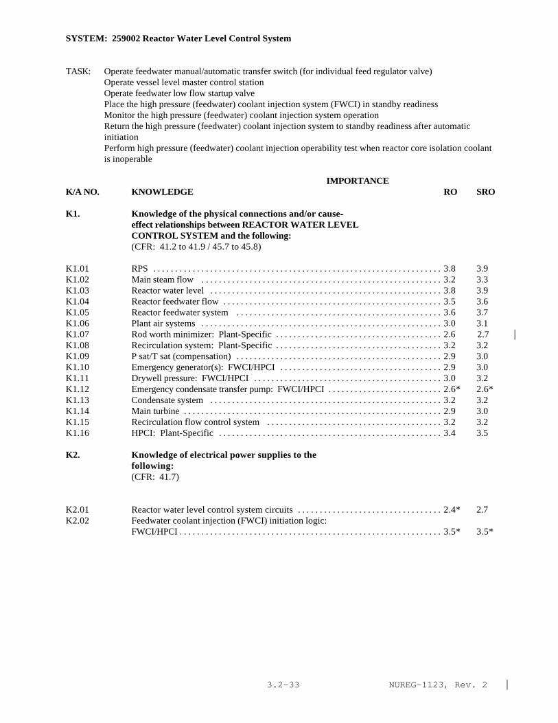
NUREG-1123, Rev. 2 |3.2-33
SYSTEM: 259002 Reactor Water Level Control System
TASK: Operate feedwater manual/automatic transfer switch (for individual feed regulator valve)Operate vessel level master control stationOperate feedwater low flow startup valvePlace the high pressure (feedwater) coolant injection system (FWCI) in standby readinessMonitor the high pressure (feedwater) coolant injection system operationReturn the high pressure (feedwater) coolant injection system to standby readiness after automaticinitiationPerform high pressure (feedwater) coolant injection operability test when reactor core isolation coolantis inoperable
IMPORTANCE K/A NO. KNOWLEDGE RO SRO
K1. Knowledge of the physical connections and/or cause-effect relationships between REACTOR WATER LEVELCONTROL SYSTEM and the following:(CFR: 41.2 to 41.9 / 45.7 to 45.8)
K1.01 RPS . . . . . . . . . . . . . . . . . . . . . . . . . . . . . . . . . . . . . . . . . . . . . . . . . . . . . . . . . . . . . . . . . . 3.8 3.9K1.02 Main steam flow . . . . . . . . . . . . . . . . . . . . . . . . . . . . . . . . . . . . . . . . . . . . . . . . . . . . . . . 3.2 3.3K1.03 Reactor water level . . . . . . . . . . . . . . . . . . . . . . . . . . . . . . . . . . . . . . . . . . . . . . . . . . . . . 3.8 3.9K1.04 Reactor feedwater flow . . . . . . . . . . . . . . . . . . . . . . . . . . . . . . . . . . . . . . . . . . . . . . . . . . 3.5 3.6K1.05 Reactor feedwater system . . . . . . . . . . . . . . . . . . . . . . . . . . . . . . . . . . . . . . . . . . . . . . . 3.6 3.7K1.06 Plant air systems . . . . . . . . . . . . . . . . . . . . . . . . . . . . . . . . . . . . . . . . . . . . . . . . . . . . . . . 3.0 3.1K1.07 Rod worth minimizer: Plant-Specific . . . . . . . . . . . . . . . . . . . . . . . . . . . . . . . . . . . . . . 2.6 2.7 |K1.08 Recirculation system: Plant-Specific . . . . . . . . . . . . . . . . . . . . . . . . . . . . . . . . . . . . . . 3.2 3.2K1.09 P sat/T sat (compensation) . . . . . . . . . . . . . . . . . . . . . . . . . . . . . . . . . . . . . . . . . . . . . . . 2.9 3.0K1.10 Emergency generator(s): FWCI/HPCI . . . . . . . . . . . . . . . . . . . . . . . . . . . . . . . . . . . . . 2.9 3.0K1.11 Drywell pressure: FWCI/HPCI . . . . . . . . . . . . . . . . . . . . . . . . . . . . . . . . . . . . . . . . . . . 3.0 3.2K1.12 Emergency condensate transfer pump: FWCI/HPCI . . . . . . . . . . . . . . . . . . . . . . . . . . 2.6* 2.6*K1.13 Condensate system . . . . . . . . . . . . . . . . . . . . . . . . . . . . . . . . . . . . . . . . . . . . . . . . . . . . . 3.2 3.2K1.14 Main turbine . . . . . . . . . . . . . . . . . . . . . . . . . . . . . . . . . . . . . . . . . . . . . . . . . . . . . . . . . . . 2.9 3.0K1.15 Recirculation flow control system . . . . . . . . . . . . . . . . . . . . . . . . . . . . . . . . . . . . . . . . 3.2 3.2K1.16 HPCI: Plant-Specific . . . . . . . . . . . . . . . . . . . . . . . . . . . . . . . . . . . . . . . . . . . . . . . . . . . 3.4 3.5
K2. Knowledge of electrical power supplies to thefollowing:(CFR: 41.7)
K2.01 Reactor water level control system circuits . . . . . . . . . . . . . . . . . . . . . . . . . . . . . . . . . 2.4* 2.7K2.02 Feedwater coolant injection (FWCI) initiation logic:
FWCI/HPCI . . . . . . . . . . . . . . . . . . . . . . . . . . . . . . . . . . . . . . . . . . . . . . . . . . . . . . . . . . . . 3.5* 3.5*

NUREG-1123, Rev. 2 |3.2-34
SYSTEM: 259002 Reactor Water Level Control System
Tasks as noted previously
IMPORTANCE K/A NO. KNOWLEDGE RO SRO
K3. Knowledge of the effect that a loss or malfunction ofthe REACTOR WATER LEVEL CONTROL SYSTEM will have onfollowing:(CFR: 41.7 / 45.4)(CFR: 41.7 / 45.5 to 45.8)
K3.01 Reactor water level . . . . . . . . . . . . . . . . . . . . . . . . . . . . . . . . . . . . . . . . . . . . . . . . . . . . . 3.8 3.8K3.02 Reactor feedwater system . . . . . . . . . . . . . . . . . . . . . . . . . . . . . . . . . . . . . . . . . . . . . . . 3.7 3.7|K3.03 Rod worth minimizer: Plant-Specific . . . . . . . . . . . . . . . . . . . . . . . . . . . . . . . . . . . . . . 2.7 2.9|K3.04 Recirculation system: Plant-Specific . . . . . . . . . . . . . . . . . . . . . . . . . . . . . . . . . . . . . . 2.9 3.0K3.05 Recirculation flow control system . . . . . . . . . . . . . . . . . . . . . . . . . . . . . . . . . . . . . . . . 2.8 2.9K3.06 Main turbine . . . . . . . . . . . . . . . . . . . . . . . . . . . . . . . . . . . . . . . . . . . . . . . . . . . . . . . . . . . 2.8 2.8K3.07 Reactor water level indication . . . . . . . . . . . . . . . . . . . . . . . . . . . . . . . . . . . . . . . . . . . . 3.4* 3.4
K4. Knowledge of REACTOR WATER LEVEL CONTROL SYSTEM designfeature(s) and/or interlocks which provide for thefollowing:(CFR: 41.7)
K4.01 Ensuring adequate NPSH for recirculation pumps:Plant-Specific . . . . . . . . . . . . . . . . . . . . . . . . . . . . . . . . . . . . . . . . . . . . . . . . . . . . . . . . . . 3.0 3.1
K4.02 Bypassing of the RWM: Plant-Specific . . . . . . . . . . . . . . . . . . . . . . . . . . . . . . . . . . . . 2.8 3.0|K4.03 Reactor feedpump runout protection: MDFP . . . . . . . . . . . . . . . . . . . . . . . . . . . . . . . . 2.8* 2.8K4.04 Reactor water level setpoint setdown following a
reactor scram . . . . . . . . . . . . . . . . . . . . . . . . . . . . . . . . . . . . . . . . . . . . . . . . . . . . . . . . . . 2.9 2.9K4.05 P sat/T sat (compensation) . . . . . . . . . . . . . . . . . . . . . . . . . . . . . . . . . . . . . . . . . . . . . . . 2.9 2.9K4.06 Control signal failure . . . . . . . . . . . . . . . . . . . . . . . . . . . . . . . . . . . . . . . . . . . . . . . . . . . . 3.1 3.2|K4.07 TDRFP 20% power interlock: TDRFP . . . . . . . . . . . . . . . . . . . . . . . . . . . . . . . . . . . . . 3.1 3.3|K4.08 TDRFP speed control: TDRFP . . . . . . . . . . . . . . . . . . . . . . . . . . . . . . . . . . . . . . . . . . . . 2.9 3.0|K4.09 Single element control (reactor water level provides|
the only input) . . . . . . . . . . . . . . . . . . . . . . . . . . . . . . . . . . . . . . . . . . . . . . . . . . . . . . . . . . 3.1 3.1K4.10 Three element control (main steam flow, reactor
feedwater flow and reactor water level provide input) . . . . . . . . . . . . . . . . . . . . . . . . . 3.4 3.4K4.11 DP control: Plant-Specific . . . . . . . . . . . . . . . . . . . . . . . . . . . . . . . . . . . . . . . . . . . . . . . 3.3 3.3K4.12 Manual and automatic control of the system . . . . . . . . . . . . . . . . . . . . . . . . . . . . . . . . 3.5 3.4K4.13 FWRV lockup . . . . . . . . . . . . . . . . . . . . . . . . . . . . . . . . . . . . . . . . . . . . . . . . . . . . . . . . . 3.5 3.6|K4.14 Selection of various instruments to provide reactor|
water level input . . . . . . . . . . . . . . . . . . . . . . . . . . . . . . . . . . . . . . . . . . . . . . . . . . . . . . . . 3.4 3.4K4.15 Automatic initiation of the feedwater system upon
receipt of an ECCS initiation signal: FWCI/HPCI . . . . . . . . . . . . . . . . . . . . . . . . . . . 4.5* 4.5*|K4.16 Dedication of feedwater string(s) to ECCS: FWCI/HPCI . . . . . . . . . . . . . . . . . . . . . . 4.5* 4.5*|K4.17 Simultaneous Manual and Auto operation of the system
(i.e. 1 FP in Auto, 1 FP in Manual) . . . . . . . . . . . . . . . . . . . . . . . . . . . . . . . . . . . . . . . . 3.1 3.0

NUREG-1123, Rev. 2 |3.2-35
SYSTEM: 259002 Reactor Water Level Control System
Tasks as noted previously
IMPORTANCE K/A NO. KNOWLEDGE RO SRO
K5. Knowledge of the operational implications of thefollowing concepts as they apply to REACTOR WATERLEVEL CONTROL SYSTEM :(CFR: 41.5 / 45.3)
K5.01 GEMAC/Foxboro/Bailey controller operation: Plant-Specific . . . . . . . . . . . . . . . . . . . . . . . . . . . . . . . . . . . . . . . . . . . . . . . . . . . . . . . . . . . . . . 3.1 3.1
K5.02 Electro/ Pneumatic converter operation . . . . . . . . . . . . . . . . . . . . . . . . . . . . . . . . . . . . 2.2* 2.4K5.03 Water level measurement . . . . . . . . . . . . . . . . . . . . . . . . . . . . . . . . . . . . . . . . . . . . . . . . 3.1 3.2K5.04 Moisture carryover . . . . . . . . . . . . . . . . . . . . . . . . . . . . . . . . . . . . . . . . . . . . . . . . . . . . . 2.3 2.3K5.05 Moisture carryunder . . . . . . . . . . . . . . . . . . . . . . . . . . . . . . . . . . . . . . . . . . . . . . . . . . . . . 2.3 2.3 |K5.06 Pump runout . . . . . . . . . . . . . . . . . . . . . . . . . . . . . . . . . . . . . . . . . . . . . . . . . . . . . . . . . . . 2.4 2.4K5.07 Turbine speed control mechanisms: TDRFP . . . . . . . . . . . . . . . . . . . . . . . . . . . . . . . . 2.7 2.7K5.08 Heat removal mechanisms: FWCI . . . . . . . . . . . . . . . . . . . . . . . . . . . . . . . . . . . . . . . . . 3.6 3.8K5.09 †Adequate core cooling: FWCI . . . . . . . . . . . . . . . . . . . . . . . . . . . . . . . . . . . . . . . . . . 3.8 4.2*
K6. Knowledge of the effect that a loss or malfunction ofthe following will have on the REACTOR WATER LEVELCONTROL SYSTEM :(CFR: 41.7 / 45.7)
K6.01 Plant air systems . . . . . . . . . . . . . . . . . . . . . . . . . . . . . . . . . . . . . . . . . . . . . . . . . . . . . . . 3.2 3.2K6.02 A.C. power . . . . . . . . . . . . . . . . . . . . . . . . . . . . . . . . . . . . . . . . . . . . . . . . . . . . . . . . . . . . 3.3 3.4K6.03 Main steam flow input . . . . . . . . . . . . . . . . . . . . . . . . . . . . . . . . . . . . . . . . . . . . . . . . . . . 3.1 3.1K6.04 Reactor feedwater flow input . . . . . . . . . . . . . . . . . . . . . . . . . . . . . . . . . . . . . . . . . . . . . 3.1 3.1K6.05 Reactor water level input . . . . . . . . . . . . . . . . . . . . . . . . . . . . . . . . . . . . . . . . . . . . . . . . . 3.5 3.5K6.06 Reactor pressure/temperature input (for water level
input compensation) . . . . . . . . . . . . . . . . . . . . . . . . . . . . . . . . . . . . . . . . . . . . . . . . . . . . 2.6 2.7K6.07 Drywell pressure input: FWCI . . . . . . . . . . . . . . . . . . . . . . . . . . . . . . . . . . . . . . . . . . . 3.0* 3.0*K6.08 Loss of dP across startup level control bypass valve:
Plant-Specific . . . . . . . . . . . . . . . . . . . . . . . . . . . . . . . . . . . . . . . . . . . . . . . . . . . . . . . . . 2.7 2.7
ABILITY
A1. Ability to predict and/or monitor changes inparameters associated with operating the REACTOR WATERLEVEL CONTROL SYSTEM controls including:(CFR: 41.5 / 45.5)
A1.01 Reactor water level . . . . . . . . . . . . . . . . . . . . . . . . . . . . . . . . . . . . . . . . . . . . . . . . . . . . . . 3.8 3.8A1.02 Reactor feedwater flow . . . . . . . . . . . . . . . . . . . . . . . . . . . . . . . . . . . . . . . . . . . . . . . . . . 3.6 3.5A1.03 Reactor power . . . . . . . . . . . . . . . . . . . . . . . . . . . . . . . . . . . . . . . . . . . . . . . . . . . . . . . . . . 3.8 3.8A1.04 Reactor water level control controller indications . . . . . . . . . . . . . . . . . . . . . . . . . . . 3.6 3.6A1.05 FWRV/startup level control position: Plant-Specific . . . . . . . . . . . . . . . . . . . . . . . . . 2.9 2.9A1.06 Feedwater string(s) selected for FWCI: FWCI . . . . . . . . . . . . . . . . . . . . . . . . . . . . . . 3.3* 3.3*A1.07 TDRFP speed: TDRFP . . . . . . . . . . . . . . . . . . . . . . . . . . . . . . . . . . . . . . . . . . . . . . . . . . 2.6 2.6

NUREG-1123, Rev. 2 |3.2-36
SYSTEM: 259002 Reactor Water Level Control System
IMPORTANCE K/A NO. KNOWLEDGE RO SRO
A2. Ability to (a) predict the impacts of the following onthe REACTOR WATER LEVEL CONTROL SYSTEM ; and (b) basedon those predictions, use procedures to correct,control, or mitigate the consequences of thoseabnormal conditions or operations:(CFR: 41.5 / 45.6)
A2.01 Loss of any number of main steam flow inputs . . . . . . . . . . . . . . . . . . . . . . . . . . . . . . . 3.3 3.4A2.02 Loss of any number of reactor feedwater flow inputs . . . . . . . . . . . . . . . . . . . . . . . . . 3.3 3.4A2.03 Loss of reactor water level input . . . . . . . . . . . . . . . . . . . . . . . . . . . . . . . . . . . . . . . . . . 3.6 3.7A2.04 RFP runout condition: Plant-Specific . . . . . . . . . . . . . . . . . . . . . . . . . . . . . . . . . . . . . 3.0 3.1A2.05 Loss of applicable plant air systems . . . . . . . . . . . . . . . . . . . . . . . . . . . . . . . . . . . . . . . 3.2 3.4A2.06 Loss of controller signal output . . . . . . . . . . . . . . . . . . . . . . . . . . . . . . . . . . . . . . . . . . . 3.3 3.4A2.07 Loss of comparator bias signal . . . . . . . . . . . . . . . . . . . . . . . . . . . . . . . . . . . . . . . . . . . 2.4 2.5A2.08 Receipt of an ECCS initiation signal: FWCI . . . . . . . . . . . . . . . . . . . . . . . . . . . . . . . . 4.5* 4.5*|A2.09 FWCI system failure alarm: FWCI . . . . . . . . . . . . . . . . . . . . . . . . . . . . . . . . . . . . . . . . 4.0 4.0
A3. Ability to monitor automatic operations of the REACTORWATER LEVEL CONTROL SYSTEM including:(CFR: 41.7 / 45.7)
A3.01 Runout flow control: Plant-Specific . . . . . . . . . . . . . . . . . . . . . . . . . . . . . . . . . . . . . . 3.0* 3.0*|A3.02 Changes in reactor water level . . . . . . . . . . . . . . . . . . . . . . . . . . . . . . . . . . . . . . . . . . . . 3.4 3.4A3.03 Changes in main steam flow . . . . . . . . . . . . . . . . . . . . . . . . . . . . . . . . . . . . . . . . . . . . . . 3.2 3.2A3.04 Changes in reactor feedwater flow . . . . . . . . . . . . . . . . . . . . . . . . . . . . . . . . . . . . . . . . 3.2 3.2A3.05 Changes in reactor power . . . . . . . . . . . . . . . . . . . . . . . . . . . . . . . . . . . . . . . . . . . . . . . . 3.4 3.4A3.06 Reactor water level setpoint setdown following a
reactor scram: Plant-Specific . . . . . . . . . . . . . . . . . . . . . . . . . . . . . . . . . . . . . . . . . . . . 3.0 3.0A3.07 FWRV lockup . . . . . . . . . . . . . . . . . . . . . . . . . . . . . . . . . . . . . . . . . . . . . . . . . . . . . . . . . 3.5 3.6A3.08 FWCI system initiation: FWCI . . . . . . . . . . . . . . . . . . . . . . . . . . . . . . . . . . . . . . . . . . . 4.0 4.0A3.09 Transfer of system from flow control to level control
mode: FWCI . . . . . . . . . . . . . . . . . . . . . . . . . . . . . . . . . . . . . . . . . . . . . . . . . . . . . . . . . . 4.3* 4.3|A3.10 TDRFP lockup: TDRFP . . . . . . . . . . . . . . . . . . . . . . . . . . . . . . . . . . . . . . . . . . . . . . . . . 3.1 3.0
A4. Ability to manually operate and/or monitor in thecontrol room:(CFR: 41.7 / 45.5 to 45.8)
A4.01 All individual component controllers in the manualmode . . . . . . . . . . . . . . . . . . . . . . . . . . . . . . . . . . . . . . . . . . . . . . . . . . . . . . . . . . . . . . . . . 3.8 3.6
A4.02 All individual component controllers in the automaticmode . . . . . . . . . . . . . . . . . . . . . . . . . . . . . . . . . . . . . . . . . . . . . . . . . . . . . . . . . . . . . . . . . 3.7 3.6
A4.03 All individual component controllers when transferringfrom manual to automatic modes . . . . . . . . . . . . . . . . . . . . . . . . . . . . . . . . . . . . . . . . . . 3.8 3.6
A4.04 FWRV lockup reset controls . . . . . . . . . . . . . . . . . . . . . . . . . . . . . . . . . . . . . . . . . . . . . 3.7 3.6A4.05 Runout flow control reset controls: Plant-Specific . . . . . . . . . . . . . . . . . . . . . . . . . . 3.8 3.5A4.06 DP/Single/three element control selector switch:
Plant-Specific . . . . . . . . . . . . . . . . . . . . . . . . . . . . . . . . . . . . . . . . . . . . . . . . . . . . . . . . . 3.1 3.2
SYSTEM: 259002 Reactor Water Level Control System

NUREG-1123, Rev. 2 |3.2-37
IMPORTANCE K/A NO. KNOWLEDGE RO SROA4.07 All individual component controllers when transferring
from automatic to manual mode 3.8 3.6A4.08 Manually initiate FWCI: FWCI 4.5* 4.5* |A4.09 TDRFP lockout reset: TDRFP 3.4 3.1A4.10 Setpoint setdown reset controls: Plant-Specific 3.1 2.9A4.11 High level lockout reset controls: Plant-Specific 3.5 3.3

NUREG-1123, Rev. 2 |3.2-38
SYSTEM: 203000 RHR/LPCI: Injection Mode (Plant Specific)
TASK: Perform lineups on the low pressure coolant injection systemPlace the low pressure coolant injection system in standby readinessMonitor operational sequence of low pressure coolant injection (LPCI) systemSecure the low pressure coolant injection systemPerform LPCI subsystem logic system functional testPerform LPCI mode inoperable testPerform LPCI mov power supply simulated auto. act test and battery serv. testsConduct LPCI independent power supply weekly battery testConduct LPCI independent power supply performance discharge testPerform low pressure coolant injection sound analysis and flow test (write in)
IMPORTANCE K/A NO. KNOWLEDGE RO SRO
K1. Knowledge of the physical connections and/or cause-effect relationships between RHR/LPCI: INJECTION MODE(PLANT SPECIFIC) and the following:(CFR: 41.2 to 41.9 / 45.7 to 45.8)
K1.01 Condensate storage and transfer system: Plant-Specific . . . . . . . . . . . . . . . . . . . . . . . . . . . . . . . . . . . . . . . . . . . . . . . . . . . . . . . . . . . . . . . 2.8 2.8
K1.02 Suppression pool . . . . . . . . . . . . . . . . . . . . . . . . . . . . . . . . . . . . . . . . . . . . . . . . . . . . . . . 3.9 3.9K1.03 Condensate transfer . . . . . . . . . . . . . . . . . . . . . . . . . . . . . . . . . . . . . . . . . . . . . . . . . . . . . 2.5* 2.6*K1.04 Keep fill system . . . . . . . . . . . . . . . . . . . . . . . . . . . . . . . . . . . . . . . . . . . . . . . . . . . . . . . . 3.3 3.4K1.05 Recirculation system: BWR-3,4 . . . . . . . . . . . . . . . . . . . . . . . . . . . . . . . . . . . . . . . . . . 3.8 3.8K1.06 Automatic depressurization . . . . . . . . . . . . . . . . . . . . . . . . . . . . . . . . . . . . . . . . . . . . . . . 3.9 3.9K1.07 D.C. electrical power . . . . . . . . . . . . . . . . . . . . . . . . . . . . . . . . . . . . . . . . . . . . . . . . . . . . 3.1 3.3K1.08 A.C. electrical power . . . . . . . . . . . . . . . . . . . . . . . . . . . . . . . . . . . . . . . . . . . . . . . . . . . . 3.5 3.5K1.09 Emergency generators . . . . . . . . . . . . . . . . . . . . . . . . . . . . . . . . . . . . . . . . . . . . . . . . . . . 3.8 3.8K1.10 ECCS room coolers . . . . . . . . . . . . . . . . . . . . . . . . . . . . . . . . . . . . . . . . . . . . . . . . . . . . . 3.2 3.2K1.11 Nuclear boiler instrumentation . . . . . . . . . . . . . . . . . . . . . . . . . . . . . . . . . . . . . . . . . . . . 3.7 3.7K1.12 Plant air systems: Plant-Specific . . . . . . . . . . . . . . . . . . . . . . . . . . . . . . . . . . . . . . . . . . 2.6* 2.7*K1.13 Drywell pressure . . . . . . . . . . . . . . . . . . . . . . . . . . . . . . . . . . . . . . . . . . . . . . . . . . . . . . . 3.9 4.0K1.14 Shutdown cooling system: Plant-Specific . . . . . . . . . . . . . . . . . . . . . . . . . . . . . . . . . . 3.6 3.7K1.15 Reactor building drain system: Plant-Specific . . . . . . . . . . . . . . . . . . . . . . . . . . . . . . . 2.4* 2.6K1.16 Component cooling water systems . . . . . . . . . . . . . . . . . . . . . . . . . . . . . . . . . . . . . . . . . 3.1 3.2K1.17 Reactor pressure . . . . . . . . . . . . . . . . . . . . . . . . . . . . . . . . . . . . . . . . . . . . . . . . . . . . . . . . 4.0 4.0K1.18 Reactor vessel: Plant-Specific . . . . . . . . . . . . . . . . . . . . . . . . . . . . . . . . . . . . . . . . . . . . 3.8 3.8
K2. Knowledge of electrical power supplies to thefollowing:(CFR: 41.7)
K2.01 Pumps . . . . . . . . . . . . . . . . . . . . . . . . . . . . . . . . . . . . . . . . . . . . . . . . . . . . . . . . . . . . . . . . 3.5* 3.5*K2.02 Valves . . . . . . . . . . . . . . . . . . . . . . . . . . . . . . . . . . . . . . . . . . . . . . . . . . . . . . . . . . . . . . . . 2.5* 2.7*K2.03 Initiation logic . . . . . . . . . . . . . . . . . . . . . . . . . . . . . . . . . . . . . . . . . . . . . . . . . . . . . . . . . 2.7* 2.9*

NUREG-1123, Rev. 2 |3.2-39
SYSTEM 203000 RHR/LPCI: Injection Mode (Plant Specific)
Tasks as noted previously
IMPORTANCE K/A NO. KNOWLEDGE RO SRO
K3. Knowledge of the effect that a loss or malfunction ofthe RHR/LPCI: INJECTION MODE (PLANT SPECIFIC) willhave on following:(CFR: 41.7 / 45.4)
K3.01 Reactor water level . . . . . . . . . . . . . . . . . . . . . . . . . . . . . . . . . . . . . . . . . . . . . . . . . . . . . 4.3* 4.4*K3.02 Suppression pool level . . . . . . . . . . . . . . . . . . . . . . . . . . . . . . . . . . . . . . . . . . . . . . . . . . 3.5 3.5K3.03 Automatic depressurization logic . . . . . . . . . . . . . . . . . . . . . . . . . . . . . . . . . . . . . . . . . 4.2* 4.3*K3.04 Adequate core cooling . . . . . . . . . . . . . . . . . . . . . . . . . . . . . . . . . . . . . . . . . . . . . . . . . . 4.6* 4.6*
K4. Knowledge of RHR/LPCI: INJECTION MODE (PLANT SPECIFIC)design feature(s) and/or interlocks which provide forthe following:(CFR: 41.7)
K4.01 Automatic system initiation/ injection . . . . . . . . . . . . . . . . . . . . . . . . . . . . . . . . . . . . . 4.2* 4.2K4.02 Prevention of piping overpressurization . . . . . . . . . . . . . . . . . . . . . . . . . . . . . . . . . . . . 3.3 3.4K4.03 Pump minimum flow protection . . . . . . . . . . . . . . . . . . . . . . . . . . . . . . . . . . . . . . . . . . 3.2 3.3K4.04 Pump motor cooling: Plant-Specific . . . . . . . . . . . . . . . . . . . . . . . . . . . . . . . . . . . . . . 2.6 2.7K4.05 Prevention of water hammer . . . . . . . . . . . . . . . . . . . . . . . . . . . . . . . . . . . . . . . . . . . . . 3.2 3.3K4.06 Adequate pump net positive suction head (interlock
suction valve open): Plant-Specific . . . . . . . . . . . . . . . . . . . . . . . . . . . . . . . . . . . . . . . 3.5 3.5K4.07 Emergency generator load sequencing . . . . . . . . . . . . . . . . . . . . . . . . . . . . . . . . . . . . . 3.7 3.9K4.08 Pump operability testing . . . . . . . . . . . . . . . . . . . . . . . . . . . . . . . . . . . . . . . . . . . . . . . . . 3.3 3 .4*K4.09 Surveillance for all operable components . . . . . . . . . . . . . . . . . . . . . . . . . . . . . . . . . . . 3.1 3.4K4.10 Dedicated injection system during automatic system
initiation (injection valve interlocks) . . . . . . . . . . . . . . . . . . . . . . . . . . . . . . . . . . . . . . 3.9 4.1K4.11 Loop selection logic: Plant-Specific . . . . . . . . . . . . . . . . . . . . . . . . . . . . . . . . . . . . . . 4.0 4.0K4.12 System redundancy . . . . . . . . . . . . . . . . . . . . . . . . . . . . . . . . . . . . . . . . . . . . . . . . . . . . . 3.5 3.6K4.13 The prevention of leakage to the environment through
LPCI/RHR heat exchanger: Plant-Specific . . . . . . . . . . . . . . . . . . . . . . . . . . . . . . . . . 3.4 3.7K4.14 †Operation from remote shutdown panel . . . . . . . . . . . . . . . . . . . . . . . . . . . . . . . . . . . 3.6 3.7K4.15 Pump runout protection: Plant-Specific . . . . . . . . . . . . . . . . . . . . . . . . . . . . . . . . . . . 2.5* 2.5
K5. Knowledge of the operational implications of thefollowing concepts as they apply to RHR/LPCI:INJECTION MODE (PLANT SPECIFIC) :(CFR: 41.5 / 45.3)
K5.01 Testable check valve operation . . . . . . . . . . . . . . . . . . . . . . . . . . . . . . . . . . . . . . . . . . . . 2.7* 2.9K5.02 †Core cooling methods . . . . . . . . . . . . . . . . . . . . . . . . . . . . . . . . . . . . . . . . . . . . . . . . . 3.5 3.7

NUREG-1123, Rev. 2 |3.2-40
SYSTEM: 203000 RHR/LPCI: Injection Mode (Plant Specific)
Tasks as noted previously
IMPORTANCE K/A NO. KNOWLEDGE RO SRO
K6. Knowledge of the effect that a loss or malfunction ofthe following will have on the RHR/LPCI: INJECTIONMODE (PLANT SPECIFIC) :(CFR: 41.7 / 45.7)
K6.01 A.C. electrical power . . . . . . . . . . . . . . . . . . . . . . . . . . . . . . . . . . . . . . . . . . . . . . . . . . . . 3.6 3.7K6.02 D.C. electrical power . . . . . . . . . . . . . . . . . . . . . . . . . . . . . . . . . . . . . . . . . . . . . . . . . . . . 2.8* 3.0*K6.03 Emergency generator . . . . . . . . . . . . . . . . . . . . . . . . . . . . . . . . . . . . . . . . . . . . . . . . . . . . 3.7 3.9K6.04 Keep fill system . . . . . . . . . . . . . . . . . . . . . . . . . . . . . . . . . . . . . . . . . . . . . . . . . . . . . . . . 3.3 3.5K6.05 Condensate storage and transfer system: Plant-Specific . . . . . . . . . . . . . . . . . . . . . . . 2.5 2.5K6.06 Suppression pool . . . . . . . . . . . . . . . . . . . . . . . . . . . . . . . . . . . . . . . . . . . . . . . . . . . . . . . 3.8 3.9|K6.07 Plant air systems: Plant-Specific . . . . . . . . . . . . . . . . . . . . . . . . . . . . . . . . . . . . . . . . . . 2.7 2.7K6.08 ECCS room cooling . . . . . . . . . . . . . . . . . . . . . . . . . . . . . . . . . . . . . . . . . . . . . . . . . . . . . 2.9 3.1K6.09 Nuclear boiler instrumentation . . . . . . . . . . . . . . . . . . . . . . . . . . . . . . . . . . . . . . . . . . . . 3.4 3.4K6.10 Component cooling water systems . . . . . . . . . . . . . . . . . . . . . . . . . . . . . . . . . . . . . . . . . 3.0 3.1K6.11 ADS . . . . . . . . . . . . . . . . . . . . . . . . . . . . . . . . . . . . . . . . . . . . . . . . . . . . . . . . . . . . . . . . . . 4.1* 4.1|K6.12 †ECCS room integrity . . . . . . . . . . . . . . . . . . . . . . . . . . . . . . . . . . . . . . . . . . . . . . . . . . . 2.7 2.9
ABILITY
A1. Ability to predict and/or monitor changes inparameters associated with operating the RHR/LPCI:INJECTION MODE (PLANT SPECIFIC) controls including:(CFR: 41.5 / 45.5)
A1.01 Reactor water level . . . . . . . . . . . . . . . . . . . . . . . . . . . . . . . . . . . . . . . . . . . . . . . . . . . . . . 4.2* 4.3*|A1.02 Reactor pressure . . . . . . . . . . . . . . . . . . . . . . . . . . . . . . . . . . . . . . . . . . . . . . . . . . . . . . . . 3.9* 4.0*|A1.03 System flow . . . . . . . . . . . . . . . . . . . . . . . . . . . . . . . . . . . . . . . . . . . . . . . . . . . . . . . . . . . 3.8 3.7A1.04 System pressure . . . . . . . . . . . . . . . . . . . . . . . . . . . . . . . . . . . . . . . . . . . . . . . . . . . . . . . . 3.6 3.6A1.05 Suppression pool level . . . . . . . . . . . . . . . . . . . . . . . . . . . . . . . . . . . . . . . . . . . . . . . . . . . 3.8 3.7A1.06 Condensate storage tank level: Plant-Specific . . . . . . . . . . . . . . . . . . . . . . . . . . . . . . . 2.4* 2.5*|A1.07 Motor amps: Plant-Specific . . . . . . . . . . . . . . . . . . . . . . . . . . . . . . . . . . . . . . . . . . . . . . 2.4* 2.5*|A1.08 †Emergency generator loading . . . . . . . . . . . . . . . . . . . . . . . . . . . . . . . . . . . . . . . . . . . . 3.7 3.8A1.09 Component cooling water systems . . . . . . . . . . . . . . . . . . . . . . . . . . . . . . . . . . . . . . . . . 2.9 2.9
A2. Ability to (a) predict the impacts of the following onthe RHR/LPCI: INJECTION MODE (PLANT SPECIFIC) ; and(b) based on those predictions, use procedures tocorrect, control, or mitigate the consequences ofthose abnormal conditions or operations:(CFR: 41.5 / 45.6)
A2.01 Inadequate net positive suction head . . . . . . . . . . . . . . . . . . . . . . . . . . . . . . . . . . . . . . . . 3.2 3.4A2.02 Pump trips . . . . . . . . . . . . . . . . . . . . . . . . . . . . . . . . . . . . . . . . . . . . . . . . . . . . . . . . . . . . . 3.5 3.5A2.03 Valve closures . . . . . . . . . . . . . . . . . . . . . . . . . . . . . . . . . . . . . . . . . . . . . . . . . . . . . . . . . . 3.2 3.3A2.04 A.C. failures . . . . . . . . . . . . . . . . . . . . . . . . . . . . . . . . . . . . . . . . . . . . . . . . . . . . . . . . . . . 3.5 3.6A2.05 D.C. failures . . . . . . . . . . . . . . . . . . . . . . . . . . . . . . . . . . . . . . . . . . . . . . . . . . . . . . . . . . . 3.0 3.2
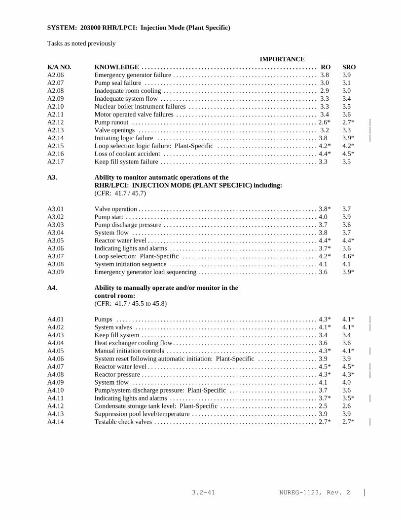
NUREG-1123, Rev. 2 |3.2-41
SYSTEM: 203000 RHR/LPCI: Injection Mode (Plant Specific)
Tasks as noted previously
IMPORTANCE K/A NO. KNOWLEDGE . . . . . . . . . . . . . . . . . . . . . . . . . . . . . . . . . . . . . . . . . . . . . . . . . . . . . . . . RO SROA2.06 Emergency generator failure . . . . . . . . . . . . . . . . . . . . . . . . . . . . . . . . . . . . . . . . . . . . . . 3.8 3.9A2.07 Pump seal failure . . . . . . . . . . . . . . . . . . . . . . . . . . . . . . . . . . . . . . . . . . . . . . . . . . . . . . . 3.0 3.1A2.08 Inadequate room cooling . . . . . . . . . . . . . . . . . . . . . . . . . . . . . . . . . . . . . . . . . . . . . . . . . 2.9 3.0A2.09 Inadequate system flow . . . . . . . . . . . . . . . . . . . . . . . . . . . . . . . . . . . . . . . . . . . . . . . . . . 3.3 3.4A2.10 Nuclear boiler instrument failures . . . . . . . . . . . . . . . . . . . . . . . . . . . . . . . . . . . . . . . . . 3.3 3.5A2.11 Motor operated valve failures . . . . . . . . . . . . . . . . . . . . . . . . . . . . . . . . . . . . . . . . . . . . . 3.4 3.6A2.12 Pump runout . . . . . . . . . . . . . . . . . . . . . . . . . . . . . . . . . . . . . . . . . . . . . . . . . . . . . . . . . . . 2.6* 2.7* |A2.13 Valve openings . . . . . . . . . . . . . . . . . . . . . . . . . . . . . . . . . . . . . . . . . . . . . . . . . . . . . . . . . 3.2 3.3 |A2.14 Initiating logic failure . . . . . . . . . . . . . . . . . . . . . . . . . . . . . . . . . . . . . . . . . . . . . . . . . . . 3.8 3.9* |A2.15 Loop selection logic failure: Plant-Specific . . . . . . . . . . . . . . . . . . . . . . . . . . . . . . . . 4.2* 4.2*A2.16 Loss of coolant accident . . . . . . . . . . . . . . . . . . . . . . . . . . . . . . . . . . . . . . . . . . . . . . . . . 4.4* 4.5*A2.17 Keep fill system failure . . . . . . . . . . . . . . . . . . . . . . . . . . . . . . . . . . . . . . . . . . . . . . . . . . 3.3 3.5
A3. Ability to monitor automatic operations of theRHR/LPCI: INJECTION MODE (PLANT SPECIFIC) including:(CFR: 41.7 / 45.7)
A3.01 Valve operation . . . . . . . . . . . . . . . . . . . . . . . . . . . . . . . . . . . . . . . . . . . . . . . . . . . . . . . . . 3.8* 3.7A3.02 Pump start . . . . . . . . . . . . . . . . . . . . . . . . . . . . . . . . . . . . . . . . . . . . . . . . . . . . . . . . . . . . . 4.0 3.9A3.03 Pump discharge pressure . . . . . . . . . . . . . . . . . . . . . . . . . . . . . . . . . . . . . . . . . . . . . . . . . 3.7 3.6A3.04 System flow . . . . . . . . . . . . . . . . . . . . . . . . . . . . . . . . . . . . . . . . . . . . . . . . . . . . . . . . . . . 3.8 3.7A3.05 Reactor water level . . . . . . . . . . . . . . . . . . . . . . . . . . . . . . . . . . . . . . . . . . . . . . . . . . . . . . 4.4* 4.4*A3.06 Indicating lights and alarms . . . . . . . . . . . . . . . . . . . . . . . . . . . . . . . . . . . . . . . . . . . . . . . 3.7* 3.6A3.07 Loop selection: Plant-Specific . . . . . . . . . . . . . . . . . . . . . . . . . . . . . . . . . . . . . . . . . . . 4.2* 4.6*A3.08 System initiation sequence . . . . . . . . . . . . . . . . . . . . . . . . . . . . . . . . . . . . . . . . . . . . . . . 4.1 4.1A3.09 Emergency generator load sequencing . . . . . . . . . . . . . . . . . . . . . . . . . . . . . . . . . . . . . . 3.6 3.9*
A4. Ability to manually operate and/or monitor in thecontrol room:(CFR: 41.7 / 45.5 to 45.8)
A4.01 Pumps . . . . . . . . . . . . . . . . . . . . . . . . . . . . . . . . . . . . . . . . . . . . . . . . . . . . . . . . . . . . . . . . 4.3* 4.1* |A4.02 System valves . . . . . . . . . . . . . . . . . . . . . . . . . . . . . . . . . . . . . . . . . . . . . . . . . . . . . . . . . . 4.1* 4.1* |A4.03 Keep fill system . . . . . . . . . . . . . . . . . . . . . . . . . . . . . . . . . . . . . . . . . . . . . . . . . . . . . . . . 3.4 3.4A4.04 Heat exchanger cooling flow . . . . . . . . . . . . . . . . . . . . . . . . . . . . . . . . . . . . . . . . . . . . . . 3.6 3.6A4.05 Manual initiation controls . . . . . . . . . . . . . . . . . . . . . . . . . . . . . . . . . . . . . . . . . . . . . . . . 4.3* 4.1* |A4.06 System reset following automatic initiation: Plant-Specific . . . . . . . . . . . . . . . . . . . 3.9 3.9A4.07 Reactor water level . . . . . . . . . . . . . . . . . . . . . . . . . . . . . . . . . . . . . . . . . . . . . . . . . . . . . . 4.5* 4.5* |A4.08 Reactor pressure . . . . . . . . . . . . . . . . . . . . . . . . . . . . . . . . . . . . . . . . . . . . . . . . . . . . . . . . 4.3* 4.3* |A4.09 System flow . . . . . . . . . . . . . . . . . . . . . . . . . . . . . . . . . . . . . . . . . . . . . . . . . . . . . . . . . . . 4.1 4.0A4.10 Pump/system discharge pressure: Plant-Specific . . . . . . . . . . . . . . . . . . . . . . . . . . . . 3.7 3.6A4.11 Indicating lights and alarms . . . . . . . . . . . . . . . . . . . . . . . . . . . . . . . . . . . . . . . . . . . . . . . 3.7* 3.5* |A4.12 Condensate storage tank level: Plant-Specific . . . . . . . . . . . . . . . . . . . . . . . . . . . . . . . 2.5 2.6A4.13 Suppression pool level/temperature . . . . . . . . . . . . . . . . . . . . . . . . . . . . . . . . . . . . . . . . 3.9 3.9A4.14 Testable check valves . . . . . . . . . . . . . . . . . . . . . . . . . . . . . . . . . . . . . . . . . . . . . . . . . . . . 2.7* 2.7* |

NUREG-1123, Rev. 2 |3.3-1
3.3 Reactor Pressure Control page
218000 Automatic Depressurization System 3.3-3239001 Main and Reheat Steam System 3.3-6241000 Reactor/Turbine Pressure Regulating System 3.3-11239002 Safety Relief Valves 3.3-18

NUREG-1123, Rev. 2 |3.3-2
This page left blank

NUREG-1123, Rev. 2 |3.3-3
SYSTEM: 218000 Automatic Depressurization System
TASK: Monitor the automatic depressurization system (ADS)Manually operate the automatic depressurization system
IMPORTANCEK/A NO. KNOWLEDGE RO SRO
K1. Knowledge of the physical connections and/or cause-effect relationships between AUTOMATICDEPRESSURIZATION SYSTEM and the following:(CFR: 41.2 to 41.9 / 45.7 to 45.8)
K1.01 RHR/LPCI: Plant-Specific . . . . . . . . . . . . . . . . . . . . . . . . . . . . . . . . . . . . . . . . . . . . . . . 4.0 4.1K1.02 Low pressure core spray: Plant-Specific . . . . . . . . . . . . . . . . . . . . . . . . . . . . . . . . . . . 4.0 4.1K1.03 Nuclear boiler instrument system . . . . . . . . . . . . . . . . . . . . . . . . . . . . . . . . . . . . . . . . . . 3.7 3.8K1.04 Drywell/containment pressure: Plant-Specific . . . . . . . . . . . . . . . . . . . . . . . . . . . . . . 3.9 4.2K1.05 Remote shutdown system: Plant-Specific . . . . . . . . . . . . . . . . . . . . . . . . . . . . . . . . . . 3.9 3.9K1.06 Safety/relief valves . . . . . . . . . . . . . . . . . . . . . . . . . . . . . . . . . . . . . . . . . . . . . . . . . . . . . . 3.9* 3.9*
K2. Knowledge of electrical power supplies to thefollowing:(CFR: 41.7)
K2.01 ADS logic . . . . . . . . . . . . . . . . . . . . . . . . . . . . . . . . . . . . . . . . . . . . . . . . . . . . . . . . . . . . . 3.1* 3.3* |
K3. Knowledge of the effect that a loss or malfunction ofthe AUTOMATIC DEPRESSURIZATION SYSTEM will have onfollowing:(CFR: 41.7 / 45.4)
K3.01 Restoration of reactor water level after a break thatdoes not depressurize the reactor when required . . . . . . . . . . . . . . . . . . . . . . . . . . . . . 4.4* 4.4*
K3.02 Ability to rapidly depressurize the reactor . . . . . . . . . . . . . . . . . . . . . . . . . . . . . . . . . . . 4.5* 4.6*
K4. Knowledge of AUTOMATIC DEPRESSURIZATION SYSTEM designfeature(s) and/or interlocks which provide for thefollowing:(CFR: 41.7)
K4.01 Prevent inadvertent initiatior of ADS logic . . . . . . . . . . . . . . . . . . . . . . . . . . . . . . . . . . 3.7 3.9K4.02 Allows manual initiation of ADS logic . . . . . . . . . . . . . . . . . . . . . . . . . . . . . . . . . . . . . . 3.8 4.0K4.03 ADS logic control . . . . . . . . . . . . . . . . . . . . . . . . . . . . . . . . . . . . . . . . . . . . . . . . . . . . . . 3.8 4.0K4.04 Insures adequate air supply to ADS valves: Plant-
Specific . . . . . . . . . . . . . . . . . . . . . . . . . . . . . . . . . . . . . . . . . . . . . . . . . . . . . . . . . . . . . . . 3.5 3.6
K5. Knowledge of the operational implications of thefollowing concepts as they apply to AUTOMATICDEPRESSURIZATION SYSTEM :(CFR: 41.5 / 45.3)
K5.01 ADS logic operation . . . . . . . . . . . . . . . . . . . . . . . . . . . . . . . . . . . . . . . . . . . . . . . . . . . . . 3.8 3.8
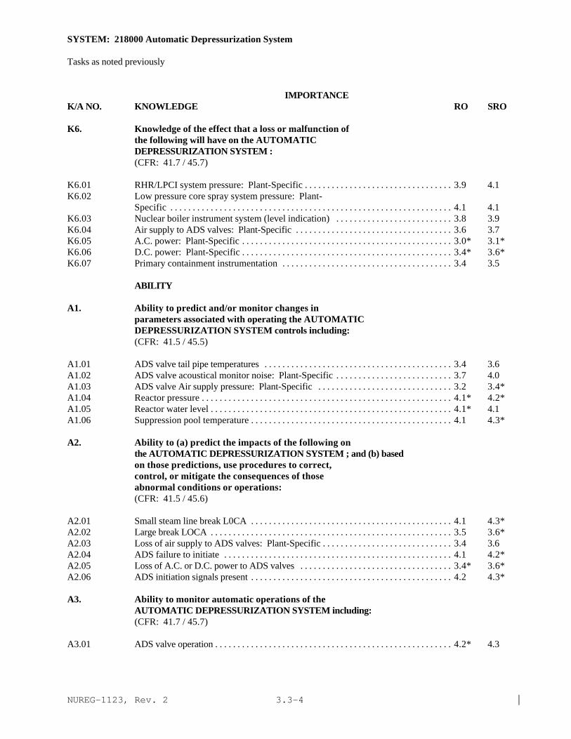
NUREG-1123, Rev. 2 |3.3-4
SYSTEM: 218000 Automatic Depressurization System
Tasks as noted previously
IMPORTANCE K/A NO. KNOWLEDGE RO SRO
K6. Knowledge of the effect that a loss or malfunction ofthe following will have on the AUTOMATICDEPRESSURIZATION SYSTEM :(CFR: 41.7 / 45.7)
K6.01 RHR/LPCI system pressure: Plant-Specific . . . . . . . . . . . . . . . . . . . . . . . . . . . . . . . . . 3.9 4.1K6.02 Low pressure core spray system pressure: Plant-
Specific . . . . . . . . . . . . . . . . . . . . . . . . . . . . . . . . . . . . . . . . . . . . . . . . . . . . . . . . . . . . . . . 4.1 4.1K6.03 Nuclear boiler instrument system (level indication) . . . . . . . . . . . . . . . . . . . . . . . . . . 3.8 3.9K6.04 Air supply to ADS valves: Plant-Specific . . . . . . . . . . . . . . . . . . . . . . . . . . . . . . . . . . . 3.6 3.7K6.05 A.C. power: Plant-Specific . . . . . . . . . . . . . . . . . . . . . . . . . . . . . . . . . . . . . . . . . . . . . . . 3.0* 3.1*K6.06 D.C. power: Plant-Specific . . . . . . . . . . . . . . . . . . . . . . . . . . . . . . . . . . . . . . . . . . . . . . . 3.4* 3.6*K6.07 Primary containment instrumentation . . . . . . . . . . . . . . . . . . . . . . . . . . . . . . . . . . . . . . 3.4 3.5
ABILITY
A1. Ability to predict and/or monitor changes inparameters associated with operating the AUTOMATICDEPRESSURIZATION SYSTEM controls including:(CFR: 41.5 / 45.5)
A1.01 ADS valve tail pipe temperatures . . . . . . . . . . . . . . . . . . . . . . . . . . . . . . . . . . . . . . . . . . 3.4 3.6A1.02 ADS valve acoustical monitor noise: Plant-Specific . . . . . . . . . . . . . . . . . . . . . . . . . . 3.7 4.0A1.03 ADS valve Air supply pressure: Plant-Specific . . . . . . . . . . . . . . . . . . . . . . . . . . . . . . 3.2 3.4*A1.04 Reactor pressure . . . . . . . . . . . . . . . . . . . . . . . . . . . . . . . . . . . . . . . . . . . . . . . . . . . . . . . . 4.1* 4.2*A1.05 Reactor water level . . . . . . . . . . . . . . . . . . . . . . . . . . . . . . . . . . . . . . . . . . . . . . . . . . . . . . 4.1* 4.1A1.06 Suppression pool temperature . . . . . . . . . . . . . . . . . . . . . . . . . . . . . . . . . . . . . . . . . . . . . 4.1 4.3*
A2. Ability to (a) predict the impacts of the following onthe AUTOMATIC DEPRESSURIZATION SYSTEM ; and (b) basedon those predictions, use procedures to correct,control, or mitigate the consequences of thoseabnormal conditions or operations:(CFR: 41.5 / 45.6)
A2.01 Small steam line break L0CA . . . . . . . . . . . . . . . . . . . . . . . . . . . . . . . . . . . . . . . . . . . . . 4.1 4.3*A2.02 Large break LOCA . . . . . . . . . . . . . . . . . . . . . . . . . . . . . . . . . . . . . . . . . . . . . . . . . . . . . . 3.5 3.6*A2.03 Loss of air supply to ADS valves: Plant-Specific . . . . . . . . . . . . . . . . . . . . . . . . . . . . . 3.4 3.6A2.04 ADS failure to initiate . . . . . . . . . . . . . . . . . . . . . . . . . . . . . . . . . . . . . . . . . . . . . . . . . . . 4.1 4.2*A2.05 Loss of A.C. or D.C. power to ADS valves . . . . . . . . . . . . . . . . . . . . . . . . . . . . . . . . . . 3.4* 3.6*A2.06 ADS initiation signals present . . . . . . . . . . . . . . . . . . . . . . . . . . . . . . . . . . . . . . . . . . . . . 4.2 4.3*
A3. Ability to monitor automatic operations of theAUTOMATIC DEPRESSURIZATION SYSTEM including:(CFR: 41.7 / 45.7)
A3.01 ADS valve operation . . . . . . . . . . . . . . . . . . . . . . . . . . . . . . . . . . . . . . . . . . . . . . . . . . . . . 4.2* 4.3

NUREG-1123, Rev. 2 |3.3-5
SYSTEM: 218000 Automatic Depressurization System
Tasks as noted previously
IMPORTANCE K/A NO. KNOWLEDGE RO SRO
A3.02 ADS valve tail pipe temperatures . . . . . . . . . . . . . . . . . . . . . . . . . . . . . . . . . . . . . . . . . . 3.6 3.7A3.03 ADS valve acoustical monitor noise: Plant-Specific . . . . . . . . . . . . . . . . . . . . . . . . . . 3.7 3.8A3.04 Primary containment pressure . . . . . . . . . . . . . . . . . . . . . . . . . . . . . . . . . . . . . . . . . . . . 3.7 3.8A3.05 Suppression pool level . . . . . . . . . . . . . . . . . . . . . . . . . . . . . . . . . . . . . . . . . . . . . . . . . . . 3.6 3.7A3.06 Suppression pool temperature . . . . . . . . . . . . . . . . . . . . . . . . . . . . . . . . . . . . . . . . . . . . . 3.9 3.9A3.07 Lights and alarms . . . . . . . . . . . . . . . . . . . . . . . . . . . . . . . . . . . . . . . . . . . . . . . . . . . . . . . 3.7 3.6A3.08 Reactor pressure . . . . . . . . . . . . . . . . . . . . . . . . . . . . . . . . . . . . . . . . . . . . . . . . . . . . . . . . 4.2* 4.3*A3.09 Reactor vessel water level . . . . . . . . . . . . . . . . . . . . . . . . . . . . . . . . . . . . . . . . . . . . . . . . 4.1* 4.2*
A4. Ability to manually operate and/or monitor in thecontrol room:(CFR: 41.7 / 45.5 to 45.8)
A4.01 ADS valves . . . . . . . . . . . . . . . . . . . . . . . . . . . . . . . . . . . . . . . . . . . . . . . . . . . . . . . . . . . . 4.4* 4.4*A4.02 ADS logic initiation . . . . . . . . . . . . . . . . . . . . . . . . . . . . . . . . . . . . . . . . . . . . . . . . . . . . . 4.2* 4.2*A4.03 ADS logic reset . . . . . . . . . . . . . . . . . . . . . . . . . . . . . . . . . . . . . . . . . . . . . . . . . . . . . . . . 4.2* 4.2*A4.04 ADS inhibit: Plant-Specific . . . . . . . . . . . . . . . . . . . . . . . . . . . . . . . . . . . . . . . . . . . . . . 4.1 4.1*A4.05 ADS timer reset . . . . . . . . . . . . . . . . . . . . . . . . . . . . . . . . . . . . . . . . . . . . . . . . . . . . . . . . 4.2* 4.2*A4.06 ADS valve tail pipe temperature . . . . . . . . . . . . . . . . . . . . . . . . . . . . . . . . . . . . . . . . . . . 3.5 3.6A4.07 ADS valve acoustical monitor noise: Plant-Specific . . . . . . . . . . . . . . . . . . . . . . . . . . 3.5 3.8A4.08 Suppression pool level . . . . . . . . . . . . . . . . . . . . . . . . . . . . . . . . . . . . . . . . . . . . . . . . . . . 3.7 3.8A4.09 Suppression pool temperature . . . . . . . . . . . . . . . . . . . . . . . . . . . . . . . . . . . . . . . . . . . . . 3.9 3.9A4.10 Lights and alarms . . . . . . . . . . . . . . . . . . . . . . . . . . . . . . . . . . . . . . . . . . . . . . . . . . . . . . . 3.8 3.8A4.11 Reactor pressure . . . . . . . . . . . . . . . . . . . . . . . . . . . . . . . . . . . . . . . . . . . . . . . . . . . . . . . . 4.3* 4.3*A4.12 Reactor vessel water level . . . . . . . . . . . . . . . . . . . . . . . . . . . . . . . . . . . . . . . . . . . . . . . . 4.2* 4.3*

NUREG-1123, Rev. 2 |3.3-6
SYSTEM: 239001 Main and Reheat Steam System
TASK: Perform lineups on the main steam systemStartup the main steam system (cold)Operate the main steam isolation valvesPlace the automatic pressure relief valves in serviceMonitor the main steam systemPerform main steam isolation valve (MSIV) fast closure test (MSIV operability testing)Perform main steam line high radiation functional test perform MSIV's, steam line drain valves and reactorsample valves logic functional testPerform main mechanical vacuum pump and valveIsolation system functional testPerform main steam isolation valve, main steam drain valve and reactor water sample valve simulatedautomatic isolation testPerform main steam isolation valves limit switch instrument functional testPerform main steam line closure scram (MSLCS) operational testPerform one train MSLCS inop surveillancePerform main steam leakage control system operational test (write in)Perform one train main steam leakage control system operability surveillance (write in)Perform monthly main steam leakage control system division 1 and division 2 fan and heater tests (writein)
IMPORTANCE K/A NO. KNOWLEDGE RO SRO
K1. Knowledge of the physical connections and/or cause-effect relationships between MAIN AND REHEAT STEAMSYSTEM and the following:(CFR: 41.2 to 41.9 / 45.7 to 45.8)
K1.01 Reactor vessel . . . . . . . . . . . . . . . . . . . . . . . . . . . . . . . . . . . . . . . . . . . . . . . . . . . . . . . . . . 3.4 3.4K1.02 SPDS/ERlS/CRIDS/GDS: Plant-Specific . . . . . . . . . . . . . . . . . . . . . . . . . . . . . . . . . . . 2.6 2.8K1.03 Main turbine . . . . . . . . . . . . . . . . . . . . . . . . . . . . . . . . . . . . . . . . . . . . . . . . . . . . . . . . . . . 3.4 3.4|K1.04 Moisture separators . . . . . . . . . . . . . . . . . . . . . . . . . . . . . . . . . . . . . . . . . . . . . . . . . . . . . 2.8 2.9|K1.05 Moisture separator reheaters: Plant-Specific . . . . . . . . . . . . . . . . . . . . . . . . . . . . . . . . 2.8 2.8K1.06 Steam bypass system . . . . . . . . . . . . . . . . . . . . . . . . . . . . . . . . . . . . . . . . . . . . . . . . . . . . 3.4 3.4K1.07 Offgas system . . . . . . . . . . . . . . . . . . . . . . . . . . . . . . . . . . . . . . . . . . . . . . . . . . . . . . . . . . 3.1 3.lK1.08 Condenser air removal system . . . . . . . . . . . . . . . . . . . . . . . . . . . . . . . . . . . . . . . . . . . . 2.9 3.1K1.09 Steam seal/gland seal system . . . . . . . . . . . . . . . . . . . . . . . . . . . . . . . . . . . . . . . . . . . . . 2.7 2.8K1.10 Extraction steam system . . . . . . . . . . . . . . . . . . . . . . . . . . . . . . . . . . . . . . . . . . . . . . . . . 2.7 2.8K1.11 High pressure heater drains and vents . . . . . . . . . . . . . . . . . . . . . . . . . . . . . . . . . . . . . . 2.5 2.5K1.12 Plant air systems . . . . . . . . . . . . . . . . . . . . . . . . . . . . . . . . . . . . . . . . . . . . . . . . . . . . . . . . 2.5 2.6K1.13 Main steam isolation valve leakage control: Plant-
Specific . . . . . . . . . . . . . . . . . . . . . . . . . . . . . . . . . . . . . . . . . . . . . . . . . . . . . . . . . . . . . . . 2.6 2.8K1.14 Positive leakage control system: Plant Specific . . . . . . . . . . . . . . . . . . . . . . . . . . . . . 2.8 3.1K1.15 Process computer/ performance monitor system . . . . . . . . . . . . . . . . . . . . . . . . . . . . 2.1* 2.1K1.16 Process radiation monitoring system . . . . . . . . . . . . . . . . . . . . . . . . . . . . . . . . . . . . . . 3.2 3.4
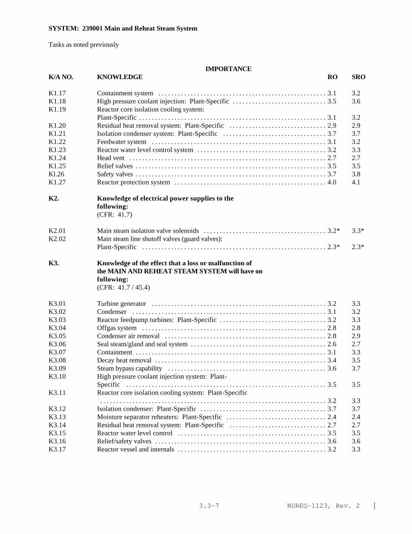
NUREG-1123, Rev. 2 |3.3-7
SYSTEM: 239001 Main and Reheat Steam System
Tasks as noted previously
IMPORTANCE K/A NO. KNOWLEDGE RO SRO
K1.17 Containment system . . . . . . . . . . . . . . . . . . . . . . . . . . . . . . . . . . . . . . . . . . . . . . . . . . . . 3.1 3.2K1.18 High pressure coolant injection: Plant-Specific . . . . . . . . . . . . . . . . . . . . . . . . . . . . . 3.5 3.6K1.19 Reactor core isolation cooling system:
Plant-Specific . . . . . . . . . . . . . . . . . . . . . . . . . . . . . . . . . . . . . . . . . . . . . . . . . . . . . . . . . . 3.1 3.2K1.20 Residual heat removal system: Plant-Specific . . . . . . . . . . . . . . . . . . . . . . . . . . . . . . 2.9 2.9K1.21 Isolation condenser system: Plant-Specific . . . . . . . . . . . . . . . . . . . . . . . . . . . . . . . . 3.7 3.7K1.22 Feedwater system . . . . . . . . . . . . . . . . . . . . . . . . . . . . . . . . . . . . . . . . . . . . . . . . . . . . . . 3.1 3.2K1.23 Reactor water level control system . . . . . . . . . . . . . . . . . . . . . . . . . . . . . . . . . . . . . . . . 3.2 3.3K1.24 Head vent . . . . . . . . . . . . . . . . . . . . . . . . . . . . . . . . . . . . . . . . . . . . . . . . . . . . . . . . . . . . . 2.7 2.7K1.25 Relief valves . . . . . . . . . . . . . . . . . . . . . . . . . . . . . . . . . . . . . . . . . . . . . . . . . . . . . . . . . . . 3.5 3.5Kl.26 Safety valves . . . . . . . . . . . . . . . . . . . . . . . . . . . . . . . . . . . . . . . . . . . . . . . . . . . . . . . . . . . 3.7 3.8K1.27 Reactor protection system . . . . . . . . . . . . . . . . . . . . . . . . . . . . . . . . . . . . . . . . . . . . . . . 4.0 4.1
K2. Knowledge of electrical power supplies to thefollowing:(CFR: 41.7)
K2.01 Main steam isolation valve solenoids . . . . . . . . . . . . . . . . . . . . . . . . . . . . . . . . . . . . . . 3.2* 3.3*K2.02 Main steam line shutoff valves (guard valves):
Plant-Specific . . . . . . . . . . . . . . . . . . . . . . . . . . . . . . . . . . . . . . . . . . . . . . . . . . . . . . . . . 2.3* 2.3*
K3. Knowledge of the effect that a loss or malfunction ofthe MAIN AND REHEAT STEAM SYSTEM will have onfollowing:(CFR: 41.7 / 45.4)
K3.01 Turbine generator . . . . . . . . . . . . . . . . . . . . . . . . . . . . . . . . . . . . . . . . . . . . . . . . . . . . . . 3.2 3.3K3.02 Condenser . . . . . . . . . . . . . . . . . . . . . . . . . . . . . . . . . . . . . . . . . . . . . . . . . . . . . . . . . . . . 3.1 3.2K3.03 Reactor feedpump turbines: Plant-Specific . . . . . . . . . . . . . . . . . . . . . . . . . . . . . . . . . 3.2 3.3K3.04 Offgas system . . . . . . . . . . . . . . . . . . . . . . . . . . . . . . . . . . . . . . . . . . . . . . . . . . . . . . . . . 2.8 2.8K3.05 Condenser air removal . . . . . . . . . . . . . . . . . . . . . . . . . . . . . . . . . . . . . . . . . . . . . . . . . . 2.8 2.9K3.06 Seal steam/gland and seal system . . . . . . . . . . . . . . . . . . . . . . . . . . . . . . . . . . . . . . . . . . 2.6 2.7K3.07 Containment . . . . . . . . . . . . . . . . . . . . . . . . . . . . . . . . . . . . . . . . . . . . . . . . . . . . . . . . . . . 3.1 3.3K3.08 Decay heat removal . . . . . . . . . . . . . . . . . . . . . . . . . . . . . . . . . . . . . . . . . . . . . . . . . . . . . 3.4 3.5K3.09 Steam bypass capability . . . . . . . . . . . . . . . . . . . . . . . . . . . . . . . . . . . . . . . . . . . . . . . . . 3.6 3.7K3.10 High pressure coolant injection system: Plant-
Specific . . . . . . . . . . . . . . . . . . . . . . . . . . . . . . . . . . . . . . . . . . . . . . . . . . . . . . . . . . . . . . 3.5 3.5K3.11 Reactor core isolation cooling system: Plant-Specific
. . . . . . . . . . . . . . . . . . . . . . . . . . . . . . . . . . . . . . . . . . . . . . . . . . . . . . . . . . . . . . . . . . . . . . 3.2 3.3K3.12 Isolation condenser: Plant-Specific . . . . . . . . . . . . . . . . . . . . . . . . . . . . . . . . . . . . . . . 3.7 3.7K3.13 Moisture separator reheaters: Plant-Specific . . . . . . . . . . . . . . . . . . . . . . . . . . . . . . . 2.4 2.4K3.14 Residual heat removal system: Plant-Specific . . . . . . . . . . . . . . . . . . . . . . . . . . . . . . 2.7 2.7K3.15 Reactor water level control . . . . . . . . . . . . . . . . . . . . . . . . . . . . . . . . . . . . . . . . . . . . . . 3.5 3.5K3.16 Relief/safety valves . . . . . . . . . . . . . . . . . . . . . . . . . . . . . . . . . . . . . . . . . . . . . . . . . . . . . 3.6 3.6K3.17 Reactor vessel and internals . . . . . . . . . . . . . . . . . . . . . . . . . . . . . . . . . . . . . . . . . . . . . . 3.2 3.3

NUREG-1123, Rev. 2 |3.3-8
SYSTEM: 239001 Main and Reheat Steam System
Tasks as noted previously
IMPORTANCE K/A NO. KNOWLEDGE RO SRO
K4. Knowledge of MAIN AND REHEAT STEAM SYSTEM designfeature(s) and/or interlocks which provide for thefollowing:(CFR: 41.7)
K4.01 Automatic isolation of steam lines . . . . . . . . . . . . . . . . . . . . . . . . . . . . . . . . . . . . . . . . 3.8 3.8K4.02 Automatic isolation and opening of drain valves:
Plant-Specific . . . . . . . . . . . . . . . . . . . . . . . . . . . . . . . . . . . . . . . . . . . . . . . . . . . . . . . . . 3.1 3.2K4.03 Insures that steam released from a steam line break
will not bypass suppression pool; BWR-6 . . . . . . . . . . . . . . . . . . . . . . . . . . . . . . . . . . 3.2 3.3K4.04 Limits steam flow during a steam line rupture to 200% . . . . . . . . . . . . . . . . . . . . . . . . 3.4 3.5K4.05 Steam flow measurement . . . . . . . . . . . . . . . . . . . . . . . . . . . . . . . . . . . . . . . . . . . . . . . . 3.1 3.2K4.06 Allows for removal or prevents escape of radioactive
steam from systems that have leaky MSIV's . . . . . . . . . . . . . . . . . . . . . . . . . . . . . . . . . 3.1 3.2K4.07 Over pressure control . . . . . . . . . . . . . . . . . . . . . . . . . . . . . . . . . . . . . . . . . . . . . . . . . . . 3.7 3.7K4.08 Removal of non condensable gases from reactor head
area . . . . . . . . . . . . . . . . . . . . . . . . . . . . . . . . . . . . . . . . . . . . . . . . . . . . . . . . . . . . . . . . . . 2.5 2.6K4.09 Equalization of pressure across the MSIV's before
opening . . . . . . . . . . . . . . . . . . . . . . . . . . . . . . . . . . . . . . . . . . . . . . . . . . . . . . . . . . . . . . . 3.3 3.3K4.10 Moisture removal from steam lines prior to admitting
steam . . . . . . . . . . . . . . . . . . . . . . . . . . . . . . . . . . . . . . . . . . . . . . . . . . . . . . . . . . . . . . . . . 2.9 3.0K4.11 Positive sealing of the MSIV's when shutdown: Plant-
Specific . . . . . . . . . . . . . . . . . . . . . . . . . . . . . . . . . . . . . . . . . . . . . . . . . . . . . . . . . . . . . . 2.9 3.1
K5. Knowledge of the operational implications of thefollowing concepts as they apply to MAIN AND REHEATSTEAM SYSTEM :(CFR: 41.5 / 45.3)
K5.01 Constant enthalpy expansion through a valve . . . . . . . . . . . . . . . . . . . . . . . . . . . . . . . . 2.0* 2.2*|K5.02 Definition and causes of steam/water hammer . . . . . . . . . . . . . . . . . . . . . . . . . . . . . . . 2.9 3.1K5.03 Definition and causes of thermal stress . . . . . . . . . . . . . . . . . . . . . . . . . . . . . . . . . . . . 2.7 2.9K5.04 Definition and reason for steam blanketing of moisture
separator reheater: Plant-Specific . . . . . . . . . . . . . . . . . . . . . . . . . . . . . . . . . . . . . . . . 1.8* 1.9*|K5.05 Flow indication . . . . . . . . . . . . . . . . . . . . . . . . . . . . . . . . . . . . . . . . . . . . . . . . . . . . . . . . 2.8 2.8K5.06 Air operated MSIV's . . . . . . . . . . . . . . . . . . . . . . . . . . . . . . . . . . . . . . . . . . . . . . . . . . . . 2.8 2.9K5.07 Hydraulic operated MSIV's . . . . . . . . . . . . . . . . . . . . . . . . . . . . . . . . . . . . . . . . . . . . . . . 2.6 2.7K5.08 Solenoid operated valves . . . . . . . . . . . . . . . . . . . . . . . . . . . . . . . . . . . . . . . . . . . . . . . . 2.6 2.7K5.09 Decay heat removal . . . . . . . . . . . . . . . . . . . . . . . . . . . . . . . . . . . . . . . . . . . . . . . . . . . . . 3.4 3.5
K6. Knowledge of the effect that a loss or malfunction ofthe following will have on the MAIN AND REHEAT STEAM SYSTEM:(CFR: 41.7 / 45.7)
K6.01 Electrical power . . . . . . . . . . . . . . . . . . . . . . . . . . . . . . . . . . . . . . . . . . . . . . . . . . . . . . . 3.1 3.3K6.02 Plant air systems . . . . . . . . . . . . . . . . . . . . . . . . . . . . . . . . . . . . . . . . . . . . . . . . . . . . . . . 3.2 3.2|K6.03 Safety valve operability . . . . . . . . . . . . . . . . . . . . . . . . . . . . . . . . . . . . . . . . . . . . . . . . . . 3.6 3.6|

NUREG-1123, Rev. 2 |3.3-9
SYSTEM: 239001 Main and Reheat Steam System
Tasks as noted previously
IMPORTANCE K/A NO. KNOWLEDGE RO SRO
K6.04 Relief valve operability: Plant-Specific . . . . . . . . . . . . . . . . . . . . . . . . . . . . . . . . . . . . 3.4 3.5K6.05 Steam line integrity . . . . . . . . . . . . . . . . . . . . . . . . . . . . . . . . . . . . . . . . . . . . . . . . . . . . . 3.6 3.7 |K6.06 MSIV isolation signal . . . . . . . . . . . . . . . . . . . . . . . . . . . . . . . . . . . . . . . . . . . . . . . . . . . 3.8 3.9K6.07 MSIV leakage control . . . . . . . . . . . . . . . . . . . . . . . . . . . . . . . . . . . . . . . . . . . . . . . . . . . 2.8 3.2K6.08 Main condenser vacuum . . . . . . . . . . . . . . . . . . . . . . . . . . . . . . . . . . . . . . . . . . . . . . . . . 3.3 3.4K6.09 PCIS/NSSSS . . . . . . . . . . . . . . . . . . . . . . . . . . . . . . . . . . . . . . . . . . . . . . . . . . . . . . . . . . . 3.9 4.1* |K6.10 ADS/low low set: Plant-Specific . . . . . . . . . . . . . . . . . . . . . . . . . . . . . . . . . . . . . . . . . 3.6 3.7
ABILITY
A1. Ability to predict and/or monitor changes inparameters associated with operating the MAIN ANDREHEAT STEAM SYSTEM controls including:(CFR: 41.5 / 45.5)
A1.01 Main steam pressure . . . . . . . . . . . . . . . . . . . . . . . . . . . . . . . . . . . . . . . . . . . . . . . . . . . . 3.6 3.6A1.02 Main steam temperature . . . . . . . . . . . . . . . . . . . . . . . . . . . . . . . . . . . . . . . . . . . . . . . . . 2.6 2.6A1.03 Reheat steam pressure: Plant-Specific . . . . . . . . . . . . . . . . . . . . . . . . . . . . . . . . . . . . . 2.2* 2.2* |A1.04 Reheater temperature: Plant-Specific . . . . . . . . . . . . . . . . . . . . . . . . . . . . . . . . . . . . . 2.3* 2.3A1.05 Main steam line radiation monitors . . . . . . . . . . . . . . . . . . . . . . . . . . . . . . . . . . . . . . . . 3.6 3.6A1.06 Air ejector process radiation monitor . . . . . . . . . . . . . . . . . . . . . . . . . . . . . . . . . . . . . . 3.4 3.4A1.07 Reactor water level . . . . . . . . . . . . . . . . . . . . . . . . . . . . . . . . . . . . . . . . . . . . . . . . . . . . . 3.7 3.7A1.08 Reactor pressure . . . . . . . . . . . . . . . . . . . . . . . . . . . . . . . . . . . . . . . . . . . . . . . . . . . . . . . 3.8 3.8A1.09 Main steam flow . . . . . . . . . . . . . . . . . . . . . . . . . . . . . . . . . . . . . . . . . . . . . . . . . . . . . . . 3.5 3.4A1.10 Reactor power . . . . . . . . . . . . . . . . . . . . . . . . . . . . . . . . . . . . . . . . . . . . . . . . . . . . . . . . . 3.8 3.8
A2. Ability to (a) predict the impacts of the following onthe MAIN AND REHEAT STEAM SYSTEM ; and (b) based onthose predictions, use procedures to correct, control,or mitigate the consequences of those abnormalconditions or operations:(CFR: 41.5 / 45.6)
A2.01 Malfunction of reactor turbine pressure regulatingsystem . . . . . . . . . . . . . . . . . . . . . . . . . . . . . . . . . . . . . . . . . . . . . . . . . . . . . . . . . . . . . . . . 3.8 3.9
A2.02 Change in steam demand and its effect on reactorpressure and power . . . . . . . . . . . . . . . . . . . . . . . . . . . . . . . . . . . . . . . . . . . . . . . . . . . . . 3.6 3.8
A2.03 MSIV closure . . . . . . . . . . . . . . . . . . . . . . . . . . . . . . . . . . . . . . . . . . . . . . . . . . . . . . . . . . 4.0 4.2A2.04 Main steam line low pressure . . . . . . . . . . . . . . . . . . . . . . . . . . . . . . . . . . . . . . . . . . . . . 3.5 3.6A2.05 †Main steam line high radiation . . . . . . . . . . . . . . . . . . . . . . . . . . . . . . . . . . . . . . . . . . . . . . . . . 3.9 4.2* |A2.06 Turbine trip without bypass valves . . . . . . . . . . . . . . . . . . . . . . . . . . . . . . . . . . . . . . . . . 4.1 4.3* |A2.07 Main steam area high temperature or differential |
temperature high . . . . . . . . . . . . . . . . . . . . . . . . . . . . . . . . . . . . . . . . . . . . . . . . . . . . . . . 3.8 3.9A2.08 Low condenser vacuum . . . . . . . . . . . . . . . . . . . . . . . . . . . . . . . . . . . . . . . . . . . . . . . . . . 3.6 3.6A2.09 Opening of head vent to drywell equipment sump with
pressure in the reactor vessel . . . . . . . . . . . . . . . . . . . . . . . . . . . . . . . . . . . . . . . . . . . . . 3.4 3.7A2.10 Closure of one or more MSIV's at power . . . . . . . . . . . . . . . . . . . . . . . . . . . . . . . . . . . 3.8 3.9
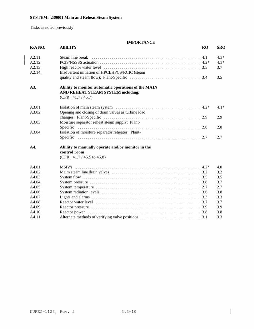
NUREG-1123, Rev. 2 |3.3-10
SYSTEM: 239001 Main and Reheat Steam System
Tasks as noted previously
IMPORTANCE K/A NO. ABILITY RO SRO
A2.11 Steam line break . . . . . . . . . . . . . . . . . . . . . . . . . . . . . . . . . . . . . . . . . . . . . . . . . . . . . . . 4.1 4.3*|A2.12 PCIS/NSSSS actuation . . . . . . . . . . . . . . . . . . . . . . . . . . . . . . . . . . . . . . . . . . . . . . . . . . . 4.2* 4.3*|A2.13 High reactor water level . . . . . . . . . . . . . . . . . . . . . . . . . . . . . . . . . . . . . . . . . . . . . . . . . 3.5 3.7A2.14 Inadvertent initiation of HPCI/HPCS/RCIC (steam
quality and steam flow): Plant-Specific . . . . . . . . . . . . . . . . . . . . . . . . . . . . . . . . . . . . 3.4 3.5
A3. Ability to monitor automatic operations of the MAINAND REHEAT STEAM SYSTEM including:(CFR: 41.7 / 45.7)
A3.01 Isolation of main steam system . . . . . . . . . . . . . . . . . . . . . . . . . . . . . . . . . . . . . . . . . . . 4.2* 4.1*A3.02 Opening and closing of drain valves as turbine load
changes: Plant-Specific . . . . . . . . . . . . . . . . . . . . . . . . . . . . . . . . . . . . . . . . . . . . . . . . . 2.9 2.9A3.03 Moisture separator reheat steam supply: Plant-
Specific . . . . . . . . . . . . . . . . . . . . . . . . . . . . . . . . . . . . . . . . . . . . . . . . . . . . . . . . . . . . . . 2.8 2.8A3.04 Isolation of moisture separator reheater: Plant-
Specific . . . . . . . . . . . . . . . . . . . . . . . . . . . . . . . . . . . . . . . . . . . . . . . . . . . . . . . . . . . . . . 2.7 2.7
A4. Ability to manually operate and/or monitor in thecontrol room:(CFR: 41.7 / 45.5 to 45.8)
A4.01 MSIV's . . . . . . . . . . . . . . . . . . . . . . . . . . . . . . . . . . . . . . . . . . . . . . . . . . . . . . . . . . . . . . . 4.2* 4.0A4.02 Maim steam line drain valves . . . . . . . . . . . . . . . . . . . . . . . . . . . . . . . . . . . . . . . . . . . . . 3.2 3.2A4.03 System flow . . . . . . . . . . . . . . . . . . . . . . . . . . . . . . . . . . . . . . . . . . . . . . . . . . . . . . . . . . . 3.5 3.5A4.04 System pressure . . . . . . . . . . . . . . . . . . . . . . . . . . . . . . . . . . . . . . . . . . . . . . . . . . . . . . . . 3.8 3.7A4.05 System temperature . . . . . . . . . . . . . . . . . . . . . . . . . . . . . . . . . . . . . . . . . . . . . . . . . . . . . 2.7 2.7A4.06 System radiation levels . . . . . . . . . . . . . . . . . . . . . . . . . . . . . . . . . . . . . . . . . . . . . . . . . . 3.6 3.8A4.07 Lights and alarms . . . . . . . . . . . . . . . . . . . . . . . . . . . . . . . . . . . . . . . . . . . . . . . . . . . . . . . 3.3 3.3A4.08 Reactor water level . . . . . . . . . . . . . . . . . . . . . . . . . . . . . . . . . . . . . . . . . . . . . . . . . . . . . 3.7 3.7A4.09 Reactor pressure . . . . . . . . . . . . . . . . . . . . . . . . . . . . . . . . . . . . . . . . . . . . . . . . . . . . . . . 3.9 3.9A4.10 Reactor power . . . . . . . . . . . . . . . . . . . . . . . . . . . . . . . . . . . . . . . . . . . . . . . . . . . . . . . . . 3.8 3.8A4.11 Alternate methods of verifying valve positions . . . . . . . . . . . . . . . . . . . . . . . . . . . . . . 3.1 3.3

NUREG-1123, Rev. 2 |3.3-11
SYSTEM: 241000 Reactor/Turbine Pressure Regulating System
TASK: Manually operate the steam dump/turbine bypass control systems Monitor steam dump/turbine bypass control system Lineup reactor pressure control system for auto operation (write in)Test control system prior to auto operation (write in) Perform lineups of the electro-hydraulic control hydraulic power unitFill the hydraulic power unit when shutdown Startup the electro-hydraulic control hydraulic power unit Operate EHC hydraulic pumps Shift EHC hydraulic coolers Operate polishing filters (fuller earth filters) Replace electro-hydraulic control system filters Fill the hydraulic power unit reservoir during normal operations Sample EHC hydraulic fluid Change accumulators during operation Monitor electro-hydraulic control hydraulic unit operation Adjust turbine load limits Operate the turbine governor test mechanism (test for operation of the overspeed trip device andmechanical trip valve) Shutdown the electro-hydraulic control power unit Discharge hydraulic fluid while shutdown Perform test of the turbine overspeed protection controller (write in)Test the turbine overspeed trip by actual turbine overspeed (write in)Perform manual trip of turbine at front standard (write in) Adjust turbine load limits Operate the turbine governor test mechanism Operate the reactor turbine pressure regulating system using manual control mode Shift control modes (mechanical [manual]/electrical) of the reactor/turbine pressure regulating system Monitor the reactor/turbine pressure regulating system What if reactor pressure is high? Shift control modes (manual/automatic) of the reactor/turbine pressure regulating system Adjust the reactor/turbine pressure regulating system pressure
IMPORTANCE K/A NO. KNOWLEDGE RO SRO
K1. Knowledge of the physical connections and/or cause-effect relationships between REACTOR/TURBINE PRESSUREREGULATING SYSTEM and the following:(CFR: 41.2 to 41.9 / 45.7 to 45.8)
K1.01 Reactor power . . . . . . . . . . . . . . . . . . . . . . . . . . . . . . . . . . . . . . . . . . . . . . . . . . . . . . . . . . 3.8 3.9K1.02 Reactor pressure . . . . . . . . . . . . . . . . . . . . . . . . . . . . . . . . . . . . . . . . . . . . . . . . . . . . . . . . 3.9 4.1K1.03 Reactor water level . . . . . . . . . . . . . . . . . . . . . . . . . . . . . . . . . . . . . . . . . . . . . . . . . . . . . . 3.6 3.7K1.04 Reactor steam flow . . . . . . . . . . . . . . . . . . . . . . . . . . . . . . . . . . . . . . . . . . . . . . . . . . . . . 3.7 3.7

NUREG-1123, Rev. 2 |3.3-12
SYSTEM: 241000 Reactor Turbine Pressure Regulating System
Tasks as noted previously
IMPORTANCE K/A NO. KNOWLEDGE RO SRO
K1.05 Main turbine steam flow . . . . . . . . . . . . . . . . . . . . . . . . . . . . . . . . . . . . . . . . . . . . . . . . . 3.5 3.6K1.06 Bypass valves . . . . . . . . . . . . . . . . . . . . . . . . . . . . . . . . . . . . . . . . . . . . . . . . . . . . . . . . . . 3.8 3.9K1.07 Main stop/throttle valves . . . . . . . . . . . . . . . . . . . . . . . . . . . . . . . . . . . . . . . . . . . . . . . . . 3.4 3.6K1.08 Control/governor valves . . . . . . . . . . . . . . . . . . . . . . . . . . . . . . . . . . . . . . . . . . . . . . . . . . 3.6 3.7K1.09 Combined intermediate valves: Plant-Specific . . . . . . . . . . . . . . . . . . . . . . . . . . . . . . . 3.1 3.4|K1.10 Front standard trip system . . . . . . . . . . . . . . . . . . . . . . . . . . . . . . . . . . . . . . . . . . . . . . . . 3.2 3.3K1.11 RPS . . . . . . . . . . . . . . . . . . . . . . . . . . . . . . . . . . . . . . . . . . . . . . . . . . . . . . . . . . . . . . . . . . 3.7 3.8K1.12 FW extraction non-return valves . . . . . . . . . . . . . . . . . . . . . . . . . . . . . . . . . . . . . . . . . . . 2.4 2.6K1.13 Bearing oil . . . . . . . . . . . . . . . . . . . . . . . . . . . . . . . . . . . . . . . . . . . . . . . . . . . . . . . . . . . . . 2.6 2.6K1.14 A.C. electrical power . . . . . . . . . . . . . . . . . . . . . . . . . . . . . . . . . . . . . . . . . . . . . . . . . . . . 2.8 2.9K1.15 D.C. electrical power . . . . . . . . . . . . . . . . . . . . . . . . . . . . . . . . . . . . . . . . . . . . . . . . . . . . 2.6 2.7K1.16 Component cooling water systems . . . . . . . . . . . . . . . . . . . . . . . . . . . . . . . . . . . . . . . . . 2.5 2.6K1.17 Turbine chest warming: EHC-Only . . . . . . . . . . . . . . . . . . . . . . . . . . . . . . . . . . . . . . . . 2.4 2.5K1.18 Turbine shell warming: EHC-Only . . . . . . . . . . . . . . . . . . . . . . . . . . . . . . . . . . . . . . . . . 2.4 2.5K1.19 Turbine acceleration . . . . . . . . . . . . . . . . . . . . . . . . . . . . . . . . . . . . . . . . . . . . . . . . . . . . . 2.6 2.6K1.20 Turbine speed . . . . . . . . . . . . . . . . . . . . . . . . . . . . . . . . . . . . . . . . . . . . . . . . . . . . . . . . . . 2.7 2.7K1.21 Turbine inlet pressure . . . . . . . . . . . . . . . . . . . . . . . . . . . . . . . . . . . . . . . . . . . . . . . . . . . 2.7 2.7K1.22 Turbine trip . . . . . . . . . . . . . . . . . . . . . . . . . . . . . . . . . . . . . . . . . . . . . . . . . . . . . . . . . . . . 3.4 3.5K1.23 Recirculation flow control system: Plant-Specific . . . . . . . . . . . . . . . . . . . . . . . . . . . 3.0 3.1K1.24 Main generator . . . . . . . . . . . . . . . . . . . . . . . . . . . . . . . . . . . . . . . . . . . . . . . . . . . . . . . . . 2.7 2.8K1.25 Stator water cooling: Plant-Specific . . . . . . . . . . . . . . . . . . . . . . . . . . . . . . . . . . . . . . . 2.8 2.8K1.26 Main turbine PMG: Plant-Specific . . . . . . . . . . . . . . . . . . . . . . . . . . . . . . . . . . . . . . . . 2.4 2.6K1.27 Condenser vacuum . . . . . . . . . . . . . . . . . . . . . . . . . . . . . . . . . . . . . . . . . . . . . . . . . . . . . . 3.1 3.1K1.28 Reactor startup . . . . . . . . . . . . . . . . . . . . . . . . . . . . . . . . . . . . . . . . . . . . . . . . . . . . . . . . . 3.2 3.2K1.29 Reactor heatup . . . . . . . . . . . . . . . . . . . . . . . . . . . . . . . . . . . . . . . . . . . . . . . . . . . . . . . . . 3.4 3.4K1.30 Reactor cooldown . . . . . . . . . . . . . . . . . . . . . . . . . . . . . . . . . . . . . . . . . . . . . . . . . . . . . . 3.2 3.3K1.31 Turbine protection . . . . . . . . . . . . . . . . . . . . . . . . . . . . . . . . . . . . . . . . . . . . . . . . . . . . . . 3.1 3.2K1.32 Turbine monitoring . . . . . . . . . . . . . . . . . . . . . . . . . . . . . . . . . . . . . . . . . . . . . . . . . . . . . . 2.7 2.8K1.33 FW extraction steam valves . . . . . . . . . . . . . . . . . . . . . . . . . . . . . . . . . . . . . . . . . . . . . . . 2.4 2.6K1.34 EGC system: Plant-Specific . . . . . . . . . . . . . . . . . . . . . . . . . . . . . . . . . . . . . . . . . . . . . . 2.8 3.3K1.35 Low pressure stop and control valves: Plant-Specific. . . . . . . . . . . . . . . . . . . . . . . . . 2.4 2.6K1.36 Primary water system: Plant-Specific . . . . . . . . . . . . . . . . . . . . . . . . . . . . . . . . . . . . . . 2.1*? 2.1*?|K1.37 Turbine stress evaluator: Plant-Specific . . . . . . . . . . . . . . . . . . . . . . . . . . . . . . . . . . . . 1.8* 1.8*K1.38 PCIS/NSSSS: Plant-Specific . . . . . . . . . . . . . . . . . . . . . . . . . . . . . . . . . . . . . . . . . . . . . 2.7 2.8
K2. Knowledge of electrical power supplies to thefollowing:(CFR: 41.7)
K2.01 Pumps . . . . . . . . . . . . . . . . . . . . . . . . . . . . . . . . . . . . . . . . . . . . . . . . . . . . . . . . . . . . . . . . 2.1* 2.2*K2.02 Controls . . . . . . . . . . . . . . . . . . . . . . . . . . . . . . . . . . . . . . . . . . . . . . . . . . . . . . . . . . . . . . . 2.1* 2.1*
K3. Knowledge of the effect that a loss or malfunction ofthe REACTOR/TURBINE PRESSURE REGULATING SYSTEM willhave on following:(CFR: 41.7 / 45.4)
K3.01 Reactor power . . . . . . . . . . . . . . . . . . . . . . . . . . . . . . . . . . . . . . . . . . . . . . . . . . . . . . . . . 4.1 4.1
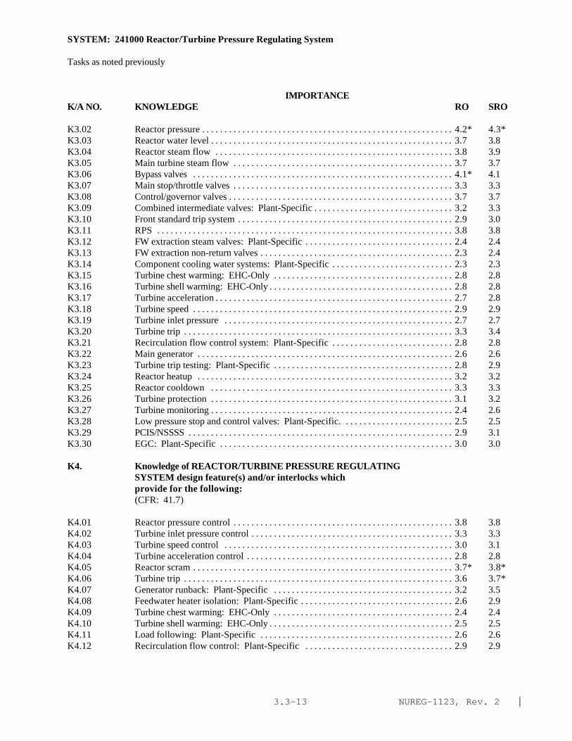
NUREG-1123, Rev. 2 |3.3-13
SYSTEM: 241000 Reactor/Turbine Pressure Regulating System
Tasks as noted previously
IMPORTANCE K/A NO. KNOWLEDGE RO SRO
K3.02 Reactor pressure . . . . . . . . . . . . . . . . . . . . . . . . . . . . . . . . . . . . . . . . . . . . . . . . . . . . . . . . 4.2* 4.3*K3.03 Reactor water level . . . . . . . . . . . . . . . . . . . . . . . . . . . . . . . . . . . . . . . . . . . . . . . . . . . . . . 3.7 3.8K3.04 Reactor steam flow . . . . . . . . . . . . . . . . . . . . . . . . . . . . . . . . . . . . . . . . . . . . . . . . . . . . . 3.8 3.9K3.05 Main turbine steam flow . . . . . . . . . . . . . . . . . . . . . . . . . . . . . . . . . . . . . . . . . . . . . . . . . 3.7 3.7K3.06 Bypass valves . . . . . . . . . . . . . . . . . . . . . . . . . . . . . . . . . . . . . . . . . . . . . . . . . . . . . . . . . . 4.1* 4.1K3.07 Main stop/throttle valves . . . . . . . . . . . . . . . . . . . . . . . . . . . . . . . . . . . . . . . . . . . . . . . . . 3.3 3.3K3.08 Control/governor valves . . . . . . . . . . . . . . . . . . . . . . . . . . . . . . . . . . . . . . . . . . . . . . . . . . 3.7 3.7K3.09 Combined intermediate valves: Plant-Specific . . . . . . . . . . . . . . . . . . . . . . . . . . . . . . . 3.2 3.3K3.10 Front standard trip system . . . . . . . . . . . . . . . . . . . . . . . . . . . . . . . . . . . . . . . . . . . . . . . . 2.9 3.0K3.11 RPS . . . . . . . . . . . . . . . . . . . . . . . . . . . . . . . . . . . . . . . . . . . . . . . . . . . . . . . . . . . . . . . . . . 3.8 3.8K3.12 FW extraction steam valves: Plant-Specific . . . . . . . . . . . . . . . . . . . . . . . . . . . . . . . . . 2.4 2.4K3.13 FW extraction non-return valves . . . . . . . . . . . . . . . . . . . . . . . . . . . . . . . . . . . . . . . . . . . 2.3 2.4K3.14 Component cooling water systems: Plant-Specific . . . . . . . . . . . . . . . . . . . . . . . . . . . 2.3 2.3K3.15 Turbine chest warming: EHC-Only . . . . . . . . . . . . . . . . . . . . . . . . . . . . . . . . . . . . . . . . 2.8 2.8K3.16 Turbine shell warming: EHC-Only . . . . . . . . . . . . . . . . . . . . . . . . . . . . . . . . . . . . . . . . . 2.8 2.8K3.17 Turbine acceleration . . . . . . . . . . . . . . . . . . . . . . . . . . . . . . . . . . . . . . . . . . . . . . . . . . . . . 2.7 2.8K3.18 Turbine speed . . . . . . . . . . . . . . . . . . . . . . . . . . . . . . . . . . . . . . . . . . . . . . . . . . . . . . . . . . 2.9 2.9K3.19 Turbine inlet pressure . . . . . . . . . . . . . . . . . . . . . . . . . . . . . . . . . . . . . . . . . . . . . . . . . . . 2.7 2.7K3.20 Turbine trip . . . . . . . . . . . . . . . . . . . . . . . . . . . . . . . . . . . . . . . . . . . . . . . . . . . . . . . . . . . . 3.3 3.4K3.21 Recirculation flow control system: Plant-Specific . . . . . . . . . . . . . . . . . . . . . . . . . . . 2.8 2.8K3.22 Main generator . . . . . . . . . . . . . . . . . . . . . . . . . . . . . . . . . . . . . . . . . . . . . . . . . . . . . . . . . 2.6 2.6K3.23 Turbine trip testing: Plant-Specific . . . . . . . . . . . . . . . . . . . . . . . . . . . . . . . . . . . . . . . . 2.8 2.9K3.24 Reactor heatup . . . . . . . . . . . . . . . . . . . . . . . . . . . . . . . . . . . . . . . . . . . . . . . . . . . . . . . . . 3.2 3.2K3.25 Reactor cooldown . . . . . . . . . . . . . . . . . . . . . . . . . . . . . . . . . . . . . . . . . . . . . . . . . . . . . . 3.3 3.3K3.26 Turbine protection . . . . . . . . . . . . . . . . . . . . . . . . . . . . . . . . . . . . . . . . . . . . . . . . . . . . . . 3.1 3.2K3.27 Turbine monitoring . . . . . . . . . . . . . . . . . . . . . . . . . . . . . . . . . . . . . . . . . . . . . . . . . . . . . . 2.4 2.6K3.28 Low pressure stop and control valves: Plant-Specific. . . . . . . . . . . . . . . . . . . . . . . . . 2.5 2.5K3.29 PCIS/NSSSS . . . . . . . . . . . . . . . . . . . . . . . . . . . . . . . . . . . . . . . . . . . . . . . . . . . . . . . . . . . 2.9 3.1K3.30 EGC: Plant-Specific . . . . . . . . . . . . . . . . . . . . . . . . . . . . . . . . . . . . . . . . . . . . . . . . . . . . 3.0 3.0
K4. Knowledge of REACTOR/TURBINE PRESSURE REGULATINGSYSTEM design feature(s) and/or interlocks whichprovide for the following:(CFR: 41.7)
K4.01 Reactor pressure control . . . . . . . . . . . . . . . . . . . . . . . . . . . . . . . . . . . . . . . . . . . . . . . . . 3.8 3.8K4.02 Turbine inlet pressure control . . . . . . . . . . . . . . . . . . . . . . . . . . . . . . . . . . . . . . . . . . . . . 3.3 3.3K4.03 Turbine speed control . . . . . . . . . . . . . . . . . . . . . . . . . . . . . . . . . . . . . . . . . . . . . . . . . . . 3.0 3.1K4.04 Turbine acceleration control . . . . . . . . . . . . . . . . . . . . . . . . . . . . . . . . . . . . . . . . . . . . . . 2.8 2.8K4.05 Reactor scram . . . . . . . . . . . . . . . . . . . . . . . . . . . . . . . . . . . . . . . . . . . . . . . . . . . . . . . . . . 3.7* 3.8*K4.06 Turbine trip . . . . . . . . . . . . . . . . . . . . . . . . . . . . . . . . . . . . . . . . . . . . . . . . . . . . . . . . . . . . 3.6 3.7*K4.07 Generator runback: Plant-Specific . . . . . . . . . . . . . . . . . . . . . . . . . . . . . . . . . . . . . . . . 3.2 3.5K4.08 Feedwater heater isolation: Plant-Specific . . . . . . . . . . . . . . . . . . . . . . . . . . . . . . . . . . 2.6 2.9K4.09 Turbine chest warming: EHC-Only . . . . . . . . . . . . . . . . . . . . . . . . . . . . . . . . . . . . . . . . 2.4 2.4K4.10 Turbine shell warming: EHC-Only . . . . . . . . . . . . . . . . . . . . . . . . . . . . . . . . . . . . . . . . . 2.5 2.5K4.11 Load following: Plant-Specific . . . . . . . . . . . . . . . . . . . . . . . . . . . . . . . . . . . . . . . . . . . 2.6 2.6K4.12 Recirculation flow control: Plant-Specific . . . . . . . . . . . . . . . . . . . . . . . . . . . . . . . . . 2.9 2.9

NUREG-1123, Rev. 2 |3.3-14
SYSTEM: 241000 Reactor/Turbine Pressure Regulating System
Tasks as noted previously
IMPORTANCE K/A NO. KNOWLEDGE RO SRO
K4.13 Turbine trip testing: Plant-Specific . . . . . . . . . . . . . . . . . . . . . . . . . . . . . . . . . . . . . . . . 2.9 3.0K4.14 Reactor/turbine pressure regulating system oil
cooling: Plant-Specific . . . . . . . . . . . . . . . . . . . . . . . . . . . . . . . . . . . . . . . . . . . . . . . . . . 2.2 2.4K4.15 Automatic pump start . . . . . . . . . . . . . . . . . . . . . . . . . . . . . . . . . . . . . . . . . . . . . . . . . . . . 2.6 2.6K4.16 Reactor cooldown . . . . . . . . . . . . . . . . . . . . . . . . . . . . . . . . . . . . . . . . . . . . . . . . . . . . . . 3.3 3.4K4.17 Turbine monitoring . . . . . . . . . . . . . . . . . . . . . . . . . . . . . . . . . . . . . . . . . . . . . . . . . . . . . . 2.4 2.6K4.18 Turbine protection . . . . . . . . . . . . . . . . . . . . . . . . . . . . . . . . . . . . . . . . . . . . . . . . . . . . . . 2.8 2.8K4.19 Steam bypass valve control . . . . . . . . . . . . . . . . . . . . . . . . . . . . . . . . . . . . . . . . . . . . . . . 3.6 3.7
K5. Knowledge of the operational Implications of thefollowing concepts as they apply to REACTOR/TURBINEPRESSURE REGULATING SYSTEM :(CFR: 41.5 / 45.3)
K5.01 Accumulator operation: Plant-Specific . . . . . . . . . . . . . . . . . . . . . . . . . . . . . . . . . . . . . 2.0* 2.1*|K5.02 Limit switch operation . . . . . . . . . . . . . . . . . . . . . . . . . . . . . . . . . . . . . . . . . . . . . . . . . . . 2.1* 2.2*|K5.03 Reactor power vs. reactor pressure . . . . . . . . . . . . . . . . . . . . . . . . . . . . . . . . . . . . . . . . 3.5 3.6K5.04 Turbine inlet pressure vs. reactor pressure . . . . . . . . . . . . . . . . . . . . . . . . . . . . . . . . . . 3.3 3.3K5.05 Turbine inlet pressure vs. turbine load . . . . . . . . . . . . . . . . . . . . . . . . . . . . . . . . . . . . . . 2.8 2.9K5.06 Turbine speed measurement . . . . . . . . . . . . . . . . . . . . . . . . . . . . . . . . . . . . . . . . . . . . . . 2.3 2.3K5.07 Unitized actuator operation: Fermi-Only . . . . . . . . . . . . . . . . . . . . . . . . . . . . . . . . . . . 2.5 3.0
K6. Knowledge of the effect that a loss or malfunction ofthe following will have on the REACTOR/TURBINEPRESSURE REGULATING SYSTEM :(CFR: 41.7 / 45.7)
K6.01 A.C. electrical power . . . . . . . . . . . . . . . . . . . . . . . . . . . . . . . . . . . . . . . . . . . . . . . . . . . . 2.8 2.9K6.02 D.C. electrical power . . . . . . . . . . . . . . . . . . . . . . . . . . . . . . . . . . . . . . . . . . . . . . . . . . . . 2.6 2.7K6.03 Component cooling water systems . . . . . . . . . . . . . . . . . . . . . . . . . . . . . . . . . . . . . . . . . 2.5 2.5K6.04 Recirculation flow control system: Plant-Specific . . . . . . . . . . . . . . . . . . . . . . . . . . . 3.0 3.0K6.05 Condenser vacuum . . . . . . . . . . . . . . . . . . . . . . . . . . . . . . . . . . . . . . . . . . . . . . . . . . . . . . 3.4 3.4K6.06 Reactor pressure . . . . . . . . . . . . . . . . . . . . . . . . . . . . . . . . . . . . . . . . . . . . . . . . . . . . . . . . 3.8* 3.9*|K6.07 Turbine inlet pressure . . . . . . . . . . . . . . . . . . . . . . . . . . . . . . . . . . . . . . . . . . . . . . . . . . . 3.4 3.4K6.08 Reactor power . . . . . . . . . . . . . . . . . . . . . . . . . . . . . . . . . . . . . . . . . . . . . . . . . . . . . . . . . . 3.6 3.7|K6.09 Main turbine steam flow . . . . . . . . . . . . . . . . . . . . . . . . . . . . . . . . . . . . . . . . . . . . . . . . . 3.1 3.1|K6.10 Bypass valves . . . . . . . . . . . . . . . . . . . . . . . . . . . . . . . . . . . . . . . . . . . . . . . . . . . . . . . . . . 3.6 3.7K6.11 Main stop/throttle valves . . . . . . . . . . . . . . . . . . . . . . . . . . . . . . . . . . . . . . . . . . . . . . . . . 3.4 3.4K6.12 Control/governor valves . . . . . . . . . . . . . . . . . . . . . . . . . . . . . . . . . . . . . . . . . . . . . . . . . . 3.3 3.4K6.13 Combined intermediate valves: Plant-Specific . . . . . . . . . . . . . . . . . . . . . . . . . . . . . . . 3.1 3.2K6.14 Bearing oil . . . . . . . . . . . . . . . . . . . . . . . . . . . . . . . . . . . . . . . . . . . . . . . . . . . . . . . . . . . . . 2.7 2.8K6.15 Turbine speed signal . . . . . . . . . . . . . . . . . . . . . . . . . . . . . . . . . . . . . . . . . . . . . . . . . . . . . 2.3 2.4K6.16 Stator water cooling system: Plant-Specific . . . . . . . . . . . . . . . . . . . . . . . . . . . . . . . . 2.9 3.1K6.17 Main turbine PMG: Plant-Specific . . . . . . . . . . . . . . . . . . . . . . . . . . . . . . . . . . . . . . . . 2.7 2.8K6.18 Low pressure stop and control valves: Plant-Specific. . . . . . . . . . . . . . . . . . . . . . . . . 2.6 2.7K6.19 Primary water system: Plant-Specific . . . . . . . . . . . . . . . . . . . . . . . . . . . . . . . . . . . . . . 2.1* 2.3*|K6.20 Main generator . . . . . . . . . . . . . . . . . . . . . . . . . . . . . . . . . . . . . . . . . . . . . . . . . . . . . . . . . 2.8 3.0

NUREG-1123, Rev. 2 |3.3-15
SYSTEM: 241000 Reactor/Turbine Pressure Regulating System
Tasks as noted previously
IMPORTANCE K/A NO. ABILITY RO SRO
A1. Ability to predict and/or monitor changes inparameters associated with operating theREACTOR/TURBINE PRESSURE REGULATING SYSTEM controlsincluding:(CFR: 41.5 / 45.5)
A1.01 Reactor pressure . . . . . . . . . . . . . . . . . . . . . . . . . . . . . . . . . . . . . . . . . . . . . . . . . . . . . . . . 3.9 3.8A1.02 Reactor power . . . . . . . . . . . . . . . . . . . . . . . . . . . . . . . . . . . . . . . . . . . . . . . . . . . . . . . . . . 4.1* 3.9A1.03 Reactor water level . . . . . . . . . . . . . . . . . . . . . . . . . . . . . . . . . . . . . . . . . . . . . . . . . . . . . . 3.7 3.7A1.04 Main turbine inlet pressure . . . . . . . . . . . . . . . . . . . . . . . . . . . . . . . . . . . . . . . . . . . . . . . 3.1 3.1A1.05 Reactor steam flow . . . . . . . . . . . . . . . . . . . . . . . . . . . . . . . . . . . . . . . . . . . . . . . . . . . . . 3.5 3.6 |A1.06 Ma in turbine steam flow . . . . . . . . . . . . . . . . . . . . . . . . . . . . . . . . . . . . . . . . . . . . . . . . . 3.2 3.2A1.07 Bypass valve position . . . . . . . . . . . . . . . . . . . . . . . . . . . . . . . . . . . . . . . . . . . . . . . . . . . . 3.8 3.7A1.08 control/governor valve position . . . . . . . . . . . . . . . . . . . . . . . . . . . . . . . . . . . . . . . . . . . 3.3 3.2A1.09 Main stop throttle valve position . . . . . . . . . . . . . . . . . . . . . . . . . . . . . . . . . . . . . . . . . . 3.3 3.3A1.10 Combined intermediate valve position: Plant-Specific. . . . . . . . . . . . . . . . . . . . . . . . 3.3 3.2A1.11 Reactor/turbine pressure regulating system oil
pressure: Plant-Specific . . . . . . . . . . . . . . . . . . . . . . . . . . . . . . . . . . . . . . . . . . . . . . . . . 2.7 2.7A1.12 Reactor/turbine pressure regulating system load
set/reference: Plant-Specific . . . . . . . . . . . . . . . . . . . . . . . . . . . . . . . . . . . . . . . . . . . . . 2.9 2.8A1.13 Main turbine speed . . . . . . . . . . . . . . . . . . . . . . . . . . . . . . . . . . . . . . . . . . . . . . . . . . . . . . 2.7 2.7A1.14 Pressure setpoint/pressure demand . . . . . . . . . . . . . . . . . . . . . . . . . . . . . . . . . . . . . . . . 3.4 3.4A1.15 Maximum combined flow limit . . . . . . . . . . . . . . . . . . . . . . . . . . . . . . . . . . . . . . . . . . . . 3.1 3.1A1.16 Load limit set: Plant-Specific . . . . . . . . . . . . . . . . . . . . . . . . . . . . . . . . . . . . . . . . . . . . 3.3 3.3A1.17 Reactor/turbine pressure regulating system oil pump
current: Plant-Specific . . . . . . . . . . . . . . . . . . . . . . . . . . . . . . . . . . . . . . . . . . . . . . . . . . 1.9* 1.9*A1.18 Reactor/turbine pressure regulating system reservoir
oil level: Plant-Specific . . . . . . . . . . . . . . . . . . . . . . . . . . . . . . . . . . . . . . . . . . . . . . . . . 2.1* 2.0*Al.l9 Reactor/turbine pressure regulating system reservoir
oil temperature: Plant-Specific . . . . . . . . . . . . . . . . . . . . . . . . . . . . . . . . . . . . . . . . . . . 2.0* 1.9*A1.20 Servo valve currents: Plant-Specific . . . . . . . . . . . . . . . . . . . . . . . . . . . . . . . . . . . . . . . 2.2* 2.1*A1.21 Main condenser vacuum . . . . . . . . . . . . . . . . . . . . . . . . . . . . . . . . . . . . . . . . . . . . . . . . . . 3.4 3.4A1.22 Reactor cooldown . . . . . . . . . . . . . . . . . . . . . . . . . . . . . . . . . . . . . . . . . . . . . . . . . . . . . . 3.4 3.3A1.23 Main turbine vibration . . . . . . . . . . . . . . . . . . . . . . . . . . . . . . . . . . . . . . . . . . . . . . . . . . . 2.8 2.8A1.24 Main turbine eccentricity . . . . . . . . . . . . . . . . . . . . . . . . . . . . . . . . . . . . . . . . . . . . . . . . 2.6 2.7A1.25 Main turbine expansion . . . . . . . . . . . . . . . . . . . . . . . . . . . . . . . . . . . . . . . . . . . . . . . . . . 2.6 2.6A1.26 Governor valve limit: Plant-Specific . . . . . . . . . . . . . . . . . . . . . . . . . . . . . . . . . . . . . . . 2.4 2.4
A2. Ability to (a) predict the impacts of the following onthe REACTOR/TURBINE PRESSURE REGULATING SYSTEM ; and(b) based on those predictions, use procedures tocorrect, control, or mitigate the consequences ofthose abnormal conditions or operations:(CFR: 41.5 / 45.6)
A2.01 Loss of turbine inlet pressure signal . . . . . . . . . . . . . . . . . . . . . . . . . . . . . . . . . . . . . . . 3.5 3.7A2.02 High reactor pressure . . . . . . . . . . . . . . . . . . . . . . . . . . . . . . . . . . . . . . . . . . . . . . . . . . . . 3.7 3.7

NUREG-1123, Rev. 2 |3.3-16
SYSTEM: 241000 Reactor/Turbine Pressure Regulating System
Tasks as noted previously
IMPORTANCE K/A NO. ABILITY RO SRO
A2.03 Failed open/closed bypass valve(s) . . . . . . . . . . . . . . . . . . . . . . . . . . . . . . . . . . . . . . . . . 4.1* 4.2*A2.04 Failed open/closed control/governor valve(s) . . . . . . . . . . . . . . . . . . . . . . . . . . . . . . . . 3.7 3.8A2.05 Failed open/closed main stop valve(s) . . . . . . . . . . . . . . . . . . . . . . . . . . . . . . . . . . . . . . 3.8 3.9A2.06 Low reactor/turbine pressure regulating system oil
pressure: Plant-Specific . . . . . . . . . . . . . . . . . . . . . . . . . . . . . . . . . . . . . . . . . . . . . . . . . 3.1 3.2A2.07 Loss of condenser vacuum . . . . . . . . . . . . . . . . . . . . . . . . . . . . . . . . . . . . . . . . . . . . . . . 3.7 3.6A2.08 Main turbine overspeed . . . . . . . . . . . . . . . . . . . . . . . . . . . . . . . . . . . . . . . . . . . . . . . . . . 3.3 3.3A2.09 Loss of generator load . . . . . . . . . . . . . . . . . . . . . . . . . . . . . . . . . . . . . . . . . . . . . . . . . . . 3.4 3.5A2.10 Loss of stator water cooling: Plant-Specific . . . . . . . . . . . . . . . . . . . . . . . . . . . . . . . . 3.1 3.2A2.11 Loss of A.C. electrical power . . . . . . . . . . . . . . . . . . . . . . . . . . . . . . . . . . . . . . . . . . . . . 3.1 3.1A2.12 Loss of D.C. electrical power . . . . . . . . . . . . . . . . . . . . . . . . . . . . . . . . . . . . . . . . . . . . . 2.7 2.8A2.13 Loss of component cooling water systems . . . . . . . . . . . . . . . . . . . . . . . . . . . . . . . . . . 2.6 2.7A2.14 Loss of main turbine PMG: Plant-Specific . . . . . . . . . . . . . . . . . . . . . . . . . . . . . . . . . 2.7 2.7A2.15 Loss of main turbine speed feedback: Plant-Specific . . . . . . . . . . . . . . . . . . . . . . . . . 2.4 2.4A2.16 Low turbine inlet pressure (loss of pressure signal) . . . . . . . . . . . . . . . . . . . . . . . . . . . 3.4 3.4A2.17 Turbine trip: Plant-Specific . . . . . . . . . . . . . . . . . . . . . . . . . . . . . . . . . . . . . . . . . . . . . . 3.8 3.8A2.18 Generator trip: Plant-Specific . . . . . . . . . . . . . . . . . . . . . . . . . . . . . . . . . . . . . . . . . . . . 3.5 3.5A2.19 Reactor scram . . . . . . . . . . . . . . . . . . . . . . . . . . . . . . . . . . . . . . . . . . . . . . . . . . . . . . . . . . 3.8 3.8A2.20 Low reactor/turbine pressure regulating system oil
level: Plant-Specific . . . . . . . . . . . . . . . . . . . . . . . . . . . . . . . . . . . . . . . . . . . . . . . . . . . . 2.5 2.6A2.21 Reactor/turbine pressure regulating system pump trip:
Plant-Specific . . . . . . . . . . . . . . . . . . . . . . . . . . . . . . . . . . . . . . . . . . . . . . . . . . . . . . . . . . 2.7 2.8A2.22 Turbine high vibration . . . . . . . . . . . . . . . . . . . . . . . . . . . . . . . . . . . . . . . . . . . . . . . . . . . 2.8 2.9A2.23 Turbine high eccentricity . . . . . . . . . . . . . . . . . . . . . . . . . . . . . . . . . . . . . . . . . . . . . . . . . 2.6 2.6A2.24 Turbine high differential expansion . . . . . . . . . . . . . . . . . . . . . . . . . . . . . . . . . . . . . . . . 2.4 2.5A2.25 Loss of primary water system: Plant-Specific . . . . . . . . . . . . . . . . . . . . . . . . . . . . . . . 2.1 2.3
A3. Ability to monitor automatic operations of theREACTOR/TURBINE PRESSURE REGULATING SYSTEM including:(CFR: 41.7 / 45.7)
A3.01 Turbine speed control: Plant-Specific . . . . . . . . . . . . . . . . . . . . . . . . . . . . . . . . . . . . . . 2.8 2.7A3.02 Turbine acceleration control: Plant-Specific . . . . . . . . . . . . . . . . . . . . . . . . . . . . . . . . 2.6 2.6A3.03 Turbine inlet pressure control . . . . . . . . . . . . . . . . . . . . . . . . . . . . . . . . . . . . . . . . . . . . . 2.8 2.7A3.04 Reactor/turbine pressure regulating system pump start:
Plant-Specific . . . . . . . . . . . . . . . . . . . . . . . . . . . . . . . . . . . . . . . . . . . . . . . . . . . . . . . . . . 2.5 2.5A3.05 Reactor/turbine pressure regulating system low
pressure turbine trip: Plant-Specific . . . . . . . . . . . . . . . . . . . . . . . . . . . . . . . . . . . . . . . 2.9 2.8A3.06 Reactor/turbine pressure regulating system low
pressure reactor scram: Plant-Specific . . . . . . . . . . . . . . . . . . . . . . . . . . . . . . . . . . . . . 3.3 3.3A3.07 Reactor/turbine pressure regulating system oil
temperature control: Plant-Specific . . . . . . . . . . . . . . . . . . . . . . . . . . . . . . . . . . . . . . . 2.3 2.3A3.08 Steam bypass valve operation . . . . . . . . . . . . . . . . . . . . . . . . . . . . . . . . . . . . . . . . . . . . . 3.8 3.8A3.09 Control/governor valve operation . . . . . . . . . . . . . . . . . . . . . . . . . . . . . . . . . . . . . . . . . . 3.3 3.2A3.10 Main stop/throttle valve operation . . . . . . . . . . . . . . . . . . . . . . . . . . . . . . . . . . . . . . . . . 3.3 3.3A3.11 Combined intermediate valve operation: Plant-Specific . . . . . . . . . . . . . . . . . . . . . . . 3.3 3.1A3.12 Turbine trip testing . . . . . . . . . . . . . . . . . . . . . . . . . . . . . . . . . . . . . . . . . . . . . . . . . . . . . . 2.9 2.9

NUREG-1123, Rev. 2 |3.3-17
SYSTEM: 241000 Reactor/Turbine Pressure Regulating System
Tasks as noted previously
IMPORTANCE K/A NO. KNOWLEDGE RO SRO
A3.13 FW heater isolation: Plant-Specific . . . . . . . . . . . . . . . . . . . . . . . . . . . . . . . . . . . . . . . 2.7 2.8A3.14 Grid load following: Plant-Specific . . . . . . . . . . . . . . . . . . . . . . . . . . . . . . . . . . . . . . . 2.6 2.7A3.15 Recirculation pump flow control: Plant-Specific . . . . . . . . . . . . . . . . . . . . . . . . . . . . 2.8 2.9A3.16 Lights and alarms . . . . . . . . . . . . . . . . . . . . . . . . . . . . . . . . . . . . . . . . . . . . . . . . . . . . . . . 3.0 2.9A3.17 Turbine runback . . . . . . . . . . . . . . . . . . . . . . . . . . . . . . . . . . . . . . . . . . . . . . . . . . . . . . . . 3.3 3.4A3.18 Turbine startup: Plant-Specific . . . . . . . . . . . . . . . . . . . . . . . . . . . . . . . . . . . . . . . . . . . 3.0 3.0 |
A4. Ability to manually operate and/or monitor in thecontrol room:(CFR: 41.7 / 45.5 to 45.8)
A4.01 Reactor power . . . . . . . . . . . . . . . . . . . . . . . . . . . . . . . . . . . . . . . . . . . . . . . . . . . . . . . . . . 3.9 4.0A4.02 Reactor pressure . . . . . . . . . . . . . . . . . . . . . . . . . . . . . . . . . . . . . . . . . . . . . . . . . . . . . . . . 4.1* 4.1* |A4.03 Reactor water level . . . . . . . . . . . . . . . . . . . . . . . . . . . . . . . . . . . . . . . . . . . . . . . . . . . . . . 3.8* 3.9A4.04 Reactor steam flow . . . . . . . . . . . . . . . . . . . . . . . . . . . . . . . . . . . . . . . . . . . . . . . . . . . . . 3.6 3.7A4.05 Main turbine steam flow . . . . . . . . . . . . . . . . . . . . . . . . . . . . . . . . . . . . . . . . . . . . . . . . . 3.3 3.3A4.06 Bypass valves (operation) . . . . . . . . . . . . . . . . . . . . . . . . . . . . . . . . . . . . . . . . . . . . . . . . 3.9 3.9A4.07 Main stop/throttle valves (operation) . . . . . . . . . . . . . . . . . . . . . . . . . . . . . . . . . . . . . . . 3.5 3.4A4.08 Control/governor valves (operation) . . . . . . . . . . . . . . . . . . . . . . . . . . . . . . . . . . . . . . . 3.5 3.4A4.09 Combined intermediate valves (operation): Plant-
Specific . . . . . . . . . . . . . . . . . . . . . . . . . . . . . . . . . . . . . . . . . . . . . . . . . . . . . . . . . . . . . . . 3.2 3.1A4.10 Reactor/turbine pressure regulating system pumps:
Plant-Specific . . . . . . . . . . . . . . . . . . . . . . . . . . . . . . . . . . . . . . . . . . . . . . . . . . . . . . . . . . 2.9 2.9A4.11 Turbine speed . . . . . . . . . . . . . . . . . . . . . . . . . . . . . . . . . . . . . . . . . . . . . . . . . . . . . . . . . . 3.1 3.1A4.12 Turbine acceleration . . . . . . . . . . . . . . . . . . . . . . . . . . . . . . . . . . . . . . . . . . . . . . . . . . . . . 3.0 3.0A4.13 Turbine inlet pressure . . . . . . . . . . . . . . . . . . . . . . . . . . . . . . . . . . . . . . . . . . . . . . . . . . . 2.9 2.9A4.14 Turbine trip . . . . . . . . . . . . . . . . . . . . . . . . . . . . . . . . . . . . . . . . . . . . . . . . . . . . . . . . . . . . 3.8 3.7A4.15 Generator load . . . . . . . . . . . . . . . . . . . . . . . . . . . . . . . . . . . . . . . . . . . . . . . . . . . . . . . . . 3.2 3.2A4.16 Lights and alarms . . . . . . . . . . . . . . . . . . . . . . . . . . . . . . . . . . . . . . . . . . . . . . . . . . . . . . . 3.3 3.2A4.17 Turbine chest warming: Plant-Specific . . . . . . . . . . . . . . . . . . . . . . . . . . . . . . . . . . . . . 2.9 2.8A4.18 Turbine shell warming: Plant-Specific . . . . . . . . . . . . . . . . . . . . . . . . . . . . . . . . . . . . . 2.9 2.8A4.19 Turbine panel controls . . . . . . . . . . . . . . . . . . . . . . . . . . . . . . . . . . . . . . . . . . . . . . . . . . . 3.5 3.4

NUREG-1123, Rev. 2 |3.3-18
SYSTEM: 239002 Relief/Safety Valves
TASK: Place the automatic pressure relief valves in service
IMPORTANCE K/A NO. KNOWLEDGE RO SRO
K1. Knowledge of the physical connections and/or cause-effect relationships between RELIEF/SAFETY VALVES andthe following:(CFR: 41.2 to 41.9 / 45.7 to 45.8)
K1.01 Nuclear boiler . . . . . . . . . . . . . . . . . . . . . . . . . . . . . . . . . . . . . . . . . . . . . . . . . . . . . . . . . 3.8 3.9K1.02 SPDS/ERIS/CRIDS/GDS: Plant-Specific . . . . . . . . . . . . . . . . . . . . . . . . . . . . . . . . . . 2.5* 2.9K1.03 Nuclear boiler instrument system . . . . . . . . . . . . . . . . . . . . . . . . . . . . . . . . . . . . . . . . . 3.5 3.6|K1.04 Main steam . . . . . . . . . . . . . . . . . . . . . . . . . . . . . . . . . . . . . . . . . . . . . . . . . . . . . . . . . . . . 3.6 3.7K1.05 Plant air systems: Plant-Specific . . . . . . . . . . . . . . . . . . . . . . . . . . . . . . . . . . . . . . . . . 3.1 3.3K1.06 Drywell instrument air/ drywell pneumatics: Plant-
Specific . . . . . . . . . . . . . . . . . . . . . . . . . . . . . . . . . . . . . . . . . . . . . . . . . . . . . . . . . . . . . . 3.4 3.6K1.07 Suppression pool . . . . . . . . . . . . . . . . . . . . . . . . . . . . . . . . . . . . . . . . . . . . . . . . . . . . . . . 3.6 3.8K1.08 Automatic depressurization system . . . . . . . . . . . . . . . . . . . . . . . . . . . . . . . . . . . . . . . . 4.0* 4.1K1.09 Drywell pressure (for safety valves which discharge to
the drywell airspace): Plant-Specific . . . . . . . . . . . . . . . . . . . . . . . . . . . . . . . . . . . . . . 4.0 4.0
K2. Knowledge of electrical power supplies to thefollowing:(CFR: 41.7)
K2.01 SRV solenoids . . . . . . . . . . . . . . . . . . . . . . . . . . . . . . . . . . . . . . . . . . . . . . . . . . . . . . . . . 2.8* 3.2*
K3. Knowledge of the effect that a loss or malfunction ofthe RELIEF/SAFETY VALVES will have on following:(CFR: 41.7 / 45.4)
K3.01 Reactor pressure control . . . . . . . . . . . . . . . . . . . . . . . . . . . . . . . . . . . . . . . . . . . . . . . . 3.9 4.0K3.02 Reactor over pressurization . . . . . . . . . . . . . . . . . . . . . . . . . . . . . . . . . . . . . . . . . . . . . . 4.2* 4.4*|K3.03 Ability to rapidly depressurize the reactor . . . . . . . . . . . . . . . . . . . . . . . . . . . . . . . . . . 4.3* 4.4*|
K4. Knowledge of RELIEF/SAFETY VALVES design feature(s)and/or interlocks which provide for the following:(CFR: 41.7)
K4.01 Insures that only one or two safety/relief valvesreopen following the initial portion of a reactorisolation event (LLS logic): Plant-Specific . . . . . . . . . . . . . . . . . . . . . . . . . . . . . . . . . 3.9 4.0
K4.02 Minimizes containment fatigue duty cycles resultingfrom relief valve cycling during decay-heat-dominantperiod late in an isolation transient (LLS logic):Plant-Specific . . . . . . . . . . . . . . . . . . . . . . . . . . . . . . . . . . . . . . . . . . . . . . . . . . . . . . . . . 3.4 3.6
K4.03 Prevents siphoning of water into SRV discharge pipingand limits loads on subsequent actuation of SRV's . . . . . . . . . . . . . . . . . . . . . . . . . . . 3.1 3.3
K4.04 Ensures even distribution of heat load to suppressionpool, and adequate steam condensing . . . . . . . . . . . . . . . . . . . . . . . . . . . . . . . . . . . . . . 3.4 3.6
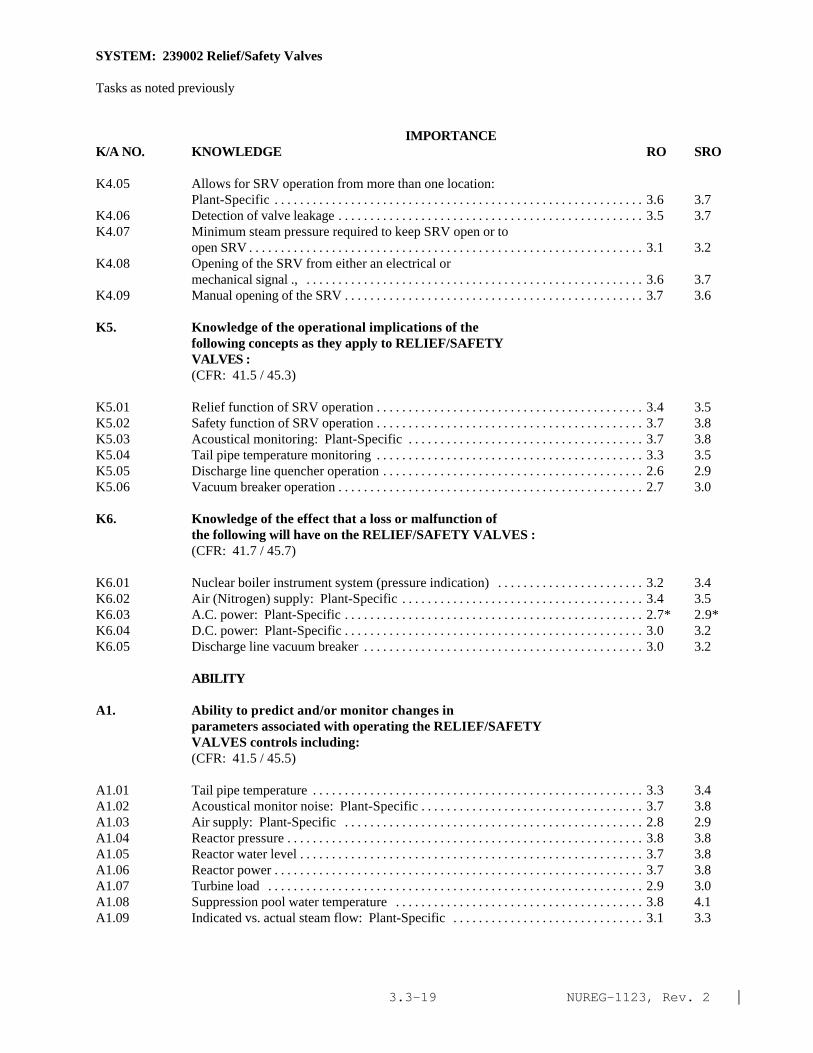
NUREG-1123, Rev. 2 |3.3-19
SYSTEM: 239002 Relief/Safety Valves
Tasks as noted previously
IMPORTANCE K/A NO. KNOWLEDGE RO SRO
K4.05 Allows for SRV operation from more than one location:Plant-Specific . . . . . . . . . . . . . . . . . . . . . . . . . . . . . . . . . . . . . . . . . . . . . . . . . . . . . . . . . . 3.6 3.7
K4.06 Detection of valve leakage . . . . . . . . . . . . . . . . . . . . . . . . . . . . . . . . . . . . . . . . . . . . . . . . 3.5 3.7K4.07 Minimum steam pressure required to keep SRV open or to
open SRV . . . . . . . . . . . . . . . . . . . . . . . . . . . . . . . . . . . . . . . . . . . . . . . . . . . . . . . . . . . . . . 3.1 3.2K4.08 Opening of the SRV from either an electrical or
mechanical signal ., . . . . . . . . . . . . . . . . . . . . . . . . . . . . . . . . . . . . . . . . . . . . . . . . . . . . . 3.6 3.7K4.09 Manual opening of the SRV . . . . . . . . . . . . . . . . . . . . . . . . . . . . . . . . . . . . . . . . . . . . . . . 3.7 3.6
K5. Knowledge of the operational implications of thefollowing concepts as they apply to RELIEF/SAFETYVALVES :(CFR: 41.5 / 45.3)
K5.01 Relief function of SRV operation . . . . . . . . . . . . . . . . . . . . . . . . . . . . . . . . . . . . . . . . . . 3.4 3.5K5.02 Safety function of SRV operation . . . . . . . . . . . . . . . . . . . . . . . . . . . . . . . . . . . . . . . . . . 3.7 3.8K5.03 Acoustical monitoring: Plant-Specific . . . . . . . . . . . . . . . . . . . . . . . . . . . . . . . . . . . . . 3.7 3.8K5.04 Tail pipe temperature monitoring . . . . . . . . . . . . . . . . . . . . . . . . . . . . . . . . . . . . . . . . . . 3.3 3.5K5.05 Discharge line quencher operation . . . . . . . . . . . . . . . . . . . . . . . . . . . . . . . . . . . . . . . . . 2.6 2.9K5.06 Vacuum breaker operation . . . . . . . . . . . . . . . . . . . . . . . . . . . . . . . . . . . . . . . . . . . . . . . . 2.7 3.0
K6. Knowledge of the effect that a loss or malfunction ofthe following will have on the RELIEF/SAFETY VALVES :(CFR: 41.7 / 45.7)
K6.01 Nuclear boiler instrument system (pressure indication) . . . . . . . . . . . . . . . . . . . . . . . 3.2 3.4K6.02 Air (Nitrogen) supply: Plant-Specific . . . . . . . . . . . . . . . . . . . . . . . . . . . . . . . . . . . . . . 3.4 3.5K6.03 A.C. power: Plant-Specific . . . . . . . . . . . . . . . . . . . . . . . . . . . . . . . . . . . . . . . . . . . . . . . 2.7* 2.9*K6.04 D.C. power: Plant-Specific . . . . . . . . . . . . . . . . . . . . . . . . . . . . . . . . . . . . . . . . . . . . . . . 3.0 3.2K6.05 Discharge line vacuum breaker . . . . . . . . . . . . . . . . . . . . . . . . . . . . . . . . . . . . . . . . . . . . 3.0 3.2
ABILITY
A1. Ability to predict and/or monitor changes inparameters associated with operating the RELIEF/SAFETYVALVES controls including:(CFR: 41.5 / 45.5)
A1.01 Tail pipe temperature . . . . . . . . . . . . . . . . . . . . . . . . . . . . . . . . . . . . . . . . . . . . . . . . . . . . 3.3 3.4A1.02 Acoustical monitor noise: Plant-Specific . . . . . . . . . . . . . . . . . . . . . . . . . . . . . . . . . . . 3.7 3.8A1.03 Air supply: Plant-Specific . . . . . . . . . . . . . . . . . . . . . . . . . . . . . . . . . . . . . . . . . . . . . . . 2.8 2.9A1.04 Reactor pressure . . . . . . . . . . . . . . . . . . . . . . . . . . . . . . . . . . . . . . . . . . . . . . . . . . . . . . . . 3.8 3.8A1.05 Reactor water level . . . . . . . . . . . . . . . . . . . . . . . . . . . . . . . . . . . . . . . . . . . . . . . . . . . . . . 3.7 3.8A1.06 Reactor power . . . . . . . . . . . . . . . . . . . . . . . . . . . . . . . . . . . . . . . . . . . . . . . . . . . . . . . . . . 3.7 3.8A1.07 Turbine load . . . . . . . . . . . . . . . . . . . . . . . . . . . . . . . . . . . . . . . . . . . . . . . . . . . . . . . . . . . 2.9 3.0A1.08 Suppression pool water temperature . . . . . . . . . . . . . . . . . . . . . . . . . . . . . . . . . . . . . . . 3.8 4.1A1.09 Indicated vs. actual steam flow: Plant-Specific . . . . . . . . . . . . . . . . . . . . . . . . . . . . . . 3.1 3.3
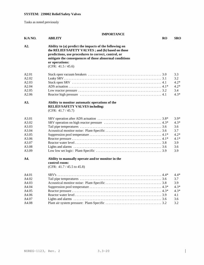
NUREG-1123, Rev. 2 |3.3-20
SYSTEM: 239002 Relief/Safety Valves
Tasks as noted previously
IMPORTANCE K/A NO. ABILITY RO SRO
A2. Ability to (a) predict the impacts of the following onthe RELIEF/SAFETY VALVES ; and (b) based on thosepredictions, use procedures to correct, control, ormitigate the consequences of those abnormal conditionsor operations:(CFR: 41.5 / 45.6)
A2.01 Stuck open vacuum breakers . . . . . . . . . . . . . . . . . . . . . . . . . . . . . . . . . . . . . . . . . . . . . . 3.0 3.3A2.02 Leaky SRV . . . . . . . . . . . . . . . . . . . . . . . . . . . . . . . . . . . . . . . . . . . . . . . . . . . . . . . . . . . . . 3.1 3.2A2.03 Stuck open SRV . . . . . . . . . . . . . . . . . . . . . . . . . . . . . . . . . . . . . . . . . . . . . . . . . . . . . . . . 4.1 4.2*A2.04 ADS actuation . . . . . . . . . . . . . . . . . . . . . . . . . . . . . . . . . . . . . . . . . . . . . . . . . . . . . . . . . . 4.1* 4.2*A2.05 Low reactor pressure . . . . . . . . . . . . . . . . . . . . . . . . . . . . . . . . . . . . . . . . . . . . . . . . . . . . 3.2 3.4A2.06 Reactor high pressure . . . . . . . . . . . . . . . . . . . . . . . . . . . . . . . . . . . . . . . . . . . . . . . . . . . 4.1 4.3*
A3. Ability to monitor automatic operations of theRELIEF/SAFETY VALVES including:(CFR: 41.7 / 45.7)
A3.01 SRV operation after ADS actuation . . . . . . . . . . . . . . . . . . . . . . . . . . . . . . . . . . . . . . . . 3.8* 3.9*A3.02 SRV operation on high reactor pressure . . . . . . . . . . . . . . . . . . . . . . . . . . . . . . . . . . . . 4.3* 4.3*A3.03 Tail pipe temperatures . . . . . . . . . . . . . . . . . . . . . . . . . . . . . . . . . . . . . . . . . . . . . . . . . . . 3.6 3.6A3.04 Acoustical monitor noise: Plant-Specific . . . . . . . . . . . . . . . . . . . . . . . . . . . . . . . . . . . 3.6 3.7A3.05 Suppression pool temperature . . . . . . . . . . . . . . . . . . . . . . . . . . . . . . . . . . . . . . . . . . . . . 4.1* 4.2*A3.06 Reactor pressure . . . . . . . . . . . . . . . . . . . . . . . . . . . . . . . . . . . . . . . . . . . . . . . . . . . . . . . . 4.1* 4.1*A3.07 Reactor water level . . . . . . . . . . . . . . . . . . . . . . . . . . . . . . . . . . . . . . . . . . . . . . . . . . . . . . 3.8 3.9A3.08 Lights and alarms . . . . . . . . . . . . . . . . . . . . . . . . . . . . . . . . . . . . . . . . . . . . . . . . . . . . . . . 3.6 3.6A3.09 Low low set logic: Plant-Specific . . . . . . . . . . . . . . . . . . . . . . . . . . . . . . . . . . . . . . . . . 3.9 3.9
A4. Ability to manually operate and/or monitor in thecontrol room:(CFR: 41.7 / 45.5 to 45.8)
A4.01 SRV's . . . . . . . . . . . . . . . . . . . . . . . . . . . . . . . . . . . . . . . . . . . . . . . . . . . . . . . . . . . . . . . . . 4.4* 4.4*A4.02 Tail pipe temperatures . . . . . . . . . . . . . . . . . . . . . . . . . . . . . . . . . . . . . . . . . . . . . . . . . . . 3.6 3.7A4.03 Acoustical monitor noise: Plant-Specific . . . . . . . . . . . . . . . . . . . . . . . . . . . . . . . . . . . 3.8 3.9A4.04 Suppression pool temperature . . . . . . . . . . . . . . . . . . . . . . . . . . . . . . . . . . . . . . . . . . . . . 4.3* 4.3*A4.05 Reactor pressure . . . . . . . . . . . . . . . . . . . . . . . . . . . . . . . . . . . . . . . . . . . . . . . . . . . . . . . . 4.3* 4.3*A4.06 Reactor water level . . . . . . . . . . . . . . . . . . . . . . . . . . . . . . . . . . . . . . . . . . . . . . . . . . . . . . 3.9 4.1A4.07 Lights and alarms . . . . . . . . . . . . . . . . . . . . . . . . . . . . . . . . . . . . . . . . . . . . . . . . . . . . . . . 3.6 3.6A4.08 Plant air system pressure: Plant-Specific . . . . . . . . . . . . . . . . . . . . . . . . . . . . . . . . . . . 3.2 3.2

NUREG-1123, Rev. 2 |3.4-1
3.4 Heat Removal from Reactor Core page
206000 High Pressure Coolant Injection System 3.4-3209002 High Pressure Core Spray System 3.4-8207000 Isolation (Emergency) Condenser 3.4-12209001 Low Pressure Core Spray System 3.4-16239001 Main and Reheat Steam System 3.4-20245000 Main Turbine Generator and Auxiliary Systems 3.4-25217000 Reactor Core Isolation Cooling System 3.4-29202001 Recirculation System 3.4-33203000 Residual Heat Removal /Low Pressure Coolant Injection: 3.4-38
Injection Mode205000 Shutdown Cooling System (RHR Shutdown Cooling Mode) 3.4-42

NUREG-1123, Rev. 2 |3.4-2
This page left blank

NUREG-1123, Rev. 2 |3.4-3
SYSTEM: 206000 High Pressure Coolant Injection System
TASK: Place the high pressure (Feedwater) coolant injection system (FWCI) in standby readinessMonitor the high pressure (feedwater) coolant injection system operationReturn the high pressure (feedwater) coolant injection system to stand-by readiness after automaticinitiationPerform lineups of the high pressure coolant injection system (write in)Manually initiate high pressure coolant injectionPerform high pressure coolant injection (HPCI) simulated automatic actuation testPerform high pressure (feedwater) coolant injection flow rate testPerform high pressure (feedwater) coolant injection (HPCI) pump operability testPerform high pressure (feedwater) coolant injection motor operated valve operability testPerform HPCI subsystem logic system functional testPerform HPCI subsystem automatic isolation logic system functional testPerform HPCI system inoperable testPerform HPCI turbine overspeed testPerform high pressure (feedwater) coolant injection operability test when reactor core isolation coolingis inoperable
IMPORTANCE K/A NO. KNOWLEDGE RO SRO
K1. Knowledge of the physical connections and/or cause-effect relationships between HIGH PRESSURE COOLANTINJECTION SYSTEM and the following:(CFR: 41.2 to 41.9 / 45.7 to 45.8)
K1.01 Reactor vessel: BWR-2,3,4 . . . . . . . . . . . . . . . . . . . . . . . . . . . . . . . . . . . . . . . . . . . . . . 3.8 3.9K1.02 Reactor water level: BWR-2,3,4 . . . . . . . . . . . . . . . . . . . . . . . . . . . . . . . . . . . . . . . . . . 4.0 4.1* |K1.03 Reactor pressure: BWR-2,3,4 . . . . . . . . . . . . . . . . . . . . . . . . . . . . . . . . . . . . . . . . . . . . 3.8 3.8 |K1.04 Reactor feedwater system: BWR-2,3,4 . . . . . . . . . . . . . . . . . . . . . . . . . . . . . . . . . . . . 3.6 3.6K1.05 Condensate storage system: BWR-2,3,4 . . . . . . . . . . . . . . . . . . . . . . . . . . . . . . . . . . . 3.7 3.7 |K1.06 Suppression chamber: BWR-2,3,4 . . . . . . . . . . . . . . . . . . . . . . . . . . . . . . . . . . . . . . . . 3.7 3.7 |K1.07 D.C. power: BWR-2,3,4 . . . . . . . . . . . . . . . . . . . . . . . . . . . . . . . . . . . . . . . . . . . . . . . . . 3.7* 3.8* |K1.08 A.C. power: BWR-2,3,4 . . . . . . . . . . . . . . . . . . . . . . . . . . . . . . . . . . . . . . . . . . . . . . . . . 3.0* 3.1* |K1.09 ECCS keep fill system: BWR-2,3,4(P-Spec) . . . . . . . . . . . . . . . . . . . . . . . . . . . . . . . . 4.0* 4.0 |K1.10 Condensate storage and transfer system: BWR-2,3,4 . . . . . . . . . . . . . . . . . . . . . . . . . 3.4 3.4K1.11 PCIS: BWR-2,3,4 . . . . . . . . . . . . . . . . . . . . . . . . . . . . . . . . . . . . . . . . . . . . . . . . . . . . . . 3.5 3.5K1.12 Nuclear boiler instrumentation: BWR-2,3,4 . . . . . . . . . . . . . . . . . . . . . . . . . . . . . . . . 3.4 3.4 |K1.13 Main condenser: BWR-2,3,4(P-Spec) . . . . . . . . . . . . . . . . . . . . . . . . . . . . . . . . . . . . . 2.8* 2.9* |K1.14 SBGT: BWR-2,3,4(P-Spec) . . . . . . . . . . . . . . . . . . . . . . . . . . . . . . . . . . . . . . . . . . . . . . 2.9 3.1K1.15 Plant air systems: BWR-2,3,4 . . . . . . . . . . . . . . . . . . . . . . . . . . . . . . . . . . . . . . . . . . . . 2.3* 2.3* |K1.16 Containment/Torus pressure: BWR-2,3,4 . . . . . . . . . . . . . . . . . . . . . . . . . . . . . . . . . . 3.5 3.5 |

NUREG-1123, Rev. 2 |3.4-4
SYSTEM: 206000 High Pressure Coolant Injection System
IMPORTANCE K/A NO. KNOWLEDGE RO SRO
K2. Knowledge of electrical power supplies to thefollowing:(CFR: 41.7)
K2.01 System valves: BWR-2,3,4 . . . . . . . . . . . . . . . . . . . . . . . . . . . . . . . . . . . . . . . . . . . . . . 3.2* 3.3*K2.02 System pumps: BWR-2,3,4 . . . . . . . . . . . . . . . . . . . . . . . . . . . . . . . . . . . . . . . . . . . . . . 2.8* 3.1*K2.03 Initiation logic: BWR-2,3,4 . . . . . . . . . . . . . . . . . . . . . . . . . . . . . . . . . . . . . . . . . . . . . 2.8* 2.9*K2.04 Turbine control circuits: BWR-2,3,4 . . . . . . . . . . . . . . . . . . . . . . . . . . . . . . . . . . . . . . 2.5* 2.7*
K3. Knowledge of the effect that a loss or malfunction ofthe HIGH PRESSURE COOLANT INJECTION SYSTEM will haveon following:(CFR: 41.7 / 45.4)
K3.01 Reactor water level control: BWR-2,3,4 . . . . . . . . . . . . . . . . . . . . . . . . . . . . . . . . . . . 4.0 4.0K3.02 Reactor pressure control: BWR-2,3,4 . . . . . . . . . . . . . . . . . . . . . . . . . . . . . . . . . . . . . 3.8* 3.8*K3.03 Suppression pool level control: BWR-2,3,4 . . . . . . . . . . . . . . . . . . . . . . . . . . . . . . . . 3.4* 3.5*
K4. Knowledge of HIGH PRESSURE COOLANT INJECTION SYSTEMdesign feature(s) and/or interlocks which provide forthe following:(CFR: 41.7)
K4.01 Turbine trips: BWR-2,3,4 . . . . . . . . . . . . . . . . . . . . . . . . . . . . . . . . . . . . . . . . . . . . . . . 3.8 3.9K4.02 System isolation: BWR-2,3,4 . . . . . . . . . . . . . . . . . . . . . . . . . . . . . . . . . . . . . . . . . . . . 3.9 4.0K4.03 Resetting turbine trips: BWR-2,3,4 . . . . . . . . . . . . . . . . . . . . . . . . . . . . . . . . . . . . . . . 4.2 4.1K4.04 Resetting system isolations: BWR-2,3,4 . . . . . . . . . . . . . . . . . . . . . . . . . . . . . . . . . . . 4.0 3.9K4.05 Preventing water hammer in turbine exhaust line
(procedural control): BWR-2,3,4 . . . . . . . . . . . . . . . . . . . . . . . . . . . . . . . . . . . . . . . . . 3.1 3.4K4.06 Preventing water hammer in pump discharge line
(procedural control ): BWR-2, 3, 4 . . . . . . . . . . . . . . . . . . . . . . . . . . . . . . . . . . . . . . . 3.2 3.4K4.07 Automatic system initiation: BWR-2,3,4 . . . . . . . . . . . . . . . . . . . . . . . . . . . . . . . . . . 4.3* 4.3K4.08 Manual system initiation: BWR-2,3,4 . . . . . . . . . . . . . . . . . . . . . . . . . . . . . . . . . . . . . 4.2* 4.3K4.09 Automatic flow control: BWR-2,3,4 . . . . . . . . . . . . . . . . . . . . . . . . . . . . . . . . . . . . . . 3.8 3.9K4.10 Surveillance for all operable components: BWR-2,3,4 . . . . . . . . . . . . . . . . . . . . . . . . 3.7 3.8K4.11 Turbine speed control: BWR-2,3,4 . . . . . . . . . . . . . . . . . . . . . . . . . . . . . . . . . . . . . . . 3.4 3.5K4.12 Condensation of shaft sealing steam: BWR-2,3,4 . . . . . . . . . . . . . . . . . . . . . . . . . . . 2.9 3.0K4.13 Turbine and pump lubrication: BWR-2,3,4 . . . . . . . . . . . . . . . . . . . . . . . . . . . . . . . . . 3.0 3.1K4.14 Control oil to turbine speed controls: BWR-2,3,4 . . . . . . . . . . . . . . . . . . . . . . . . . . . 3.4 3.4K4.15 Low speed turning of the turbine rotor: BWR-2,3,4(P-
Spec) . . . . . . . . . . . . . . . . . . . . . . . . . . . . . . . . . . . . . . . . . . . . . . . . . . . . . . . . . . . . . . . . . 3.2 3.2K4.16 Minimizing fission product concentration in the
condensate storage tank (valve closures on systeminitiation): BWR-2,3,4(P-Spec) . . . . . . . . . . . . . . . . . . . . . . . . . . . . . . . . . . . . . . . . . . 3.1 3.3
K4.17 Protection against draining the condensate storagetank to the suppression pool: BWR-2,3,4 . . . . . . . . . . . . . . . . . . . . . . . . . . . . . . . . . . 3.4 3.4
K4.18 Pump minimum flow: BWR-2,3,4 . . . . . . . . . . . . . . . . . . . . . . . . . . . . . . . . . . . . . . . . 3.2 3.3K4.19 Automatic transfer of HPCI pump suction: BWR-2,3,4 . . . . . . . . . . . . . . . . . . . . . . . 3.7 3.8

NUREG-1123, Rev. 2 |3.4-5
SYSTEM: 206000 High Pressure Coolant Injection System
Tasks as noted previously
IMPORTANCE K/A NO. KNOWLEDGE RO SRO
K5. Knowledge of the operational implications of thefollowing concepts as they apply to HIGH PRESSURECOOLANT INJECTION SYSTEM :(CFR: 41.5 / 45.3)
K5.01 Turbine operation: BWR-2,3,4 . . . . . . . . . . . . . . . . . . . . . . . . . . . . . . . . . . . . . . . . . . . 3.3 3.4K5.02 Turbine shaft sealing: BWR-2,3,4 . . . . . . . . . . . . . . . . . . . . . . . . . . . . . . . . . . . . . . . . . 2.8 2.9K5.03 GEMAC controllers: BWR-2,3,4(P-Spec) . . . . . . . . . . . . . . . . . . . . . . . . . . . . . . . . . . 3.1 3.1K5.04 Indications of pump cavitation: BWR-2,3,4 . . . . . . . . . . . . . . . . . . . . . . . . . . . . . . . . . 2.6* 2.7* |K5.05 Turbine speed control: BWR-2,3,4 . . . . . . . . . . . . . . . . . . . . . . . . . . . . . . . . . . . . . . . . 3.3 3.3K5.06 Turbine speed measurement: BWR-2,3,4 . . . . . . . . . . . . . . . . . . . . . . . . . . . . . . . . . . . 2.6* 2.6K5.07 System venting: BWR-2,3,4 . . . . . . . . . . . . . . . . . . . . . . . . . . . . . . . . . . . . . . . . . . . . . . 2.8 2.8K5.08 Vacuum breaker operation: BWR-2,3,4 . . . . . . . . . . . . . . . . . . . . . . . . . . . . . . . . . . . . 3.0 3.2K5.09 Testable check valve operation: BWR-2,3,4 . . . . . . . . . . . . . . . . . . . . . . . . . . . . . . . . . 2.7* 2.8K5.10 Assist core cooling: BWR-2,3,4 . . . . . . . . . . . . . . . . . . . . . . . . . . . . . . . . . . . . . . . . . . 3.5 3.5
K6. Knowledge of the effect that a loss or malfunction ofthe following will have on the HIGH PRESSURE COOLANTINJECTION SYSTEM :(CFR: 41.7 / 45.7)
K6.01 Plant air systems: BWR-2,3,4 . . . . . . . . . . . . . . . . . . . . . . . . . . . . . . . . . . . . . . . . . . . . 2.3* 2.3* |K6.02 D.C. power: BWR-2,3,4 . . . . . . . . . . . . . . . . . . . . . . . . . . . . . . . . . . . . . . . . . . . . . . . . . 3.3 3.7* |K6.03 A.C. power: BWR-2,3,4 . . . . . . . . . . . . . . . . . . . . . . . . . . . . . . . . . . . . . . . . . . . . . . . . . 2.9 3.1* |K6.04 Condensate storage tank level: BWR-2,3,4 . . . . . . . . . . . . . . . . . . . . . . . . . . . . . . . . . 3.5 3.7K6.05 Suppression pool level: BWR-2,3,4 . . . . . . . . . . . . . . . . . . . . . . . . . . . . . . . . . . . . . . . 3.5 3.7K6.06 SBGTS: BWR-2,3,4(P-Spec) . . . . . . . . . . . . . . . . . . . . . . . . . . . . . . . . . . . . . . . . . . . . . 3.1 3.2K6.07 ECCS keep fill system: BWR-2,3,4(P-Spec) . . . . . . . . . . . . . . . . . . . . . . . . . . . . . . . . 3.4 3.4K6.08 Reactor pressure: BWR-2,3,4 . . . . . . . . . . . . . . . . . . . . . . . . . . . . . . . . . . . . . . . . . . . . 3.8 3.8K6.09 Condensate storage and transfer system: BWR-2,3,4 . . . . . . . . . . . . . . . . . . . . . . . . . 3.5 3.5K6.10 PCIS: BWR-2,3,4 . . . . . . . . . . . . . . . . . . . . . . . . . . . . . . . . . . . . . . . . . . . . . . . . . . . . . . 3.8 4.0K6.11 Nuclear boiler instrumentation: BWR-2,3,4 . . . . . . . . . . . . . . . . . . . . . . . . . . . . . . . . 3.6 3.7K6.12 Reactor water level: BWR-2,3,4 . . . . . . . . . . . . . . . . . . . . . . . . . . . . . . . . . . . . . . . . . . 4.2* 4.3* |
ABILITY
A1. Ability to predict and/or monitor changes inparameters associated with operating the HIGH PRESSURECOOLANT INJECTION SYSTEM controls including:(CFR: 41.5 / 45.5)
A1.01 Reactor water level: BWR-2,3,4 . . . . . . . . . . . . . . . . . . . . . . . . . . . . . . . . . . . . . . . . . . 4.3* 4.4* |A1.02 Reactor pressure: BWR-2,3,4 . . . . . . . . . . . . . . . . . . . . . . . . . . . . . . . . . . . . . . . . . . . . 4.2* 4.2A1.03 Condensate storage tank level: BWR-2,3,4 . . . . . . . . . . . . . . . . . . . . . . . . . . . . . . . . . 3.5 3.6A1.04 Suppression pool level: BWR-2,3,4 . . . . . . . . . . . . . . . . . . . . . . . . . . . . . . . . . . . . . . . 3.7 3.8A1.05 Suppression pool temperature: BWR-2,3,4 . . . . . . . . . . . . . . . . . . . . . . . . . . . . . . . . . 4.1 4.2A1.06 System flow: BWR-2,3,4 . . . . . . . . . . . . . . . . . . . . . . . . . . . . . . . . . . . . . . . . . . . . . . . . 3.8 3.7
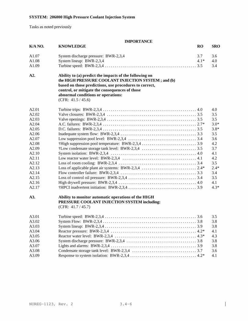
NUREG-1123, Rev. 2 |3.4-6
SYSTEM: 206000 High Pressure Coolant Injection System
Tasks as noted previously
IMPORTANCE K/A NO. KNOWLEDGE RO SRO
A1.07 System discharge pressure: BWR-2,3,4 3.7 3.6A1.08 System lineup: BWR-2,3,4 4.1* 4.0A1.09 Turbine speed: BWR-2,3,4 . . . . . . . . . . . . . . . . . . . . . . . . . . . . . . . . . . . . . . . . . . . . . . . 3.5 3.4
A2. Ability to (a) predict the impacts of the following onthe HIGH PRESSURE COOLANT INJECTION SYSTEM ; and (b)based on those predictions, use procedures to correct,control, or mitigate the consequences of thoseabnormal conditions or operations:(CFR: 41.5 / 45.6)
A2.01 Turbine trips: BWR-2,3,4 . . . . . . . . . . . . . . . . . . . . . . . . . . . . . . . . . . . . . . . . . . . . . . . . 4.0 4.0A2.02 Valve closures: BWR-2,3,4 . . . . . . . . . . . . . . . . . . . . . . . . . . . . . . . . . . . . . . . . . . . . . . 3.5 3.5A2.03 Valve openings: BWR-2,3,4 . . . . . . . . . . . . . . . . . . . . . . . . . . . . . . . . . . . . . . . . . . . . . . 3.5 3.5A2.04 A.C. failures: BWR-2,3,4 . . . . . . . . . . . . . . . . . . . . . . . . . . . . . . . . . . . . . . . . . . . . . . . . 2.7* 3.0*A2.05 D.C. failures: BWR-2,3,4 . . . . . . . . . . . . . . . . . . . . . . . . . . . . . . . . . . . . . . . . . . . . . . . . 3.5 3.8*A2.06 Inadequate system flow: BWR-2,3,4 . . . . . . . . . . . . . . . . . . . . . . . . . . . . . . . . . . . . . . . 3.3 3.5A2.07 Low suppression pool level: BWR-2,3,4 . . . . . . . . . . . . . . . . . . . . . . . . . . . . . . . . . . . 3.4 3.6A2.08 †High suppression pool temperature: BWR-2,3,4 . . . . . . . . . . . . . . . . . . . . . . . . . . . . 3.9 4.2A2.09 †Low condensate storage tank level: BWR-2,3,4 . . . . . . . . . . . . . . . . . . . . . . . . . . . . 3.5 3.7A2.10 System isolation: BWR-2,3,4 . . . . . . . . . . . . . . . . . . . . . . . . . . . . . . . . . . . . . . . . . . . . 4.0 4.1A2.11 Low reactor water level: BWR-2,3,4 . . . . . . . . . . . . . . . . . . . . . . . . . . . . . . . . . . . . . . 4.1 4.2A2.12 Loss of room cooling: BWR-2,3,4 . . . . . . . . . . . . . . . . . . . . . . . . . . . . . . . . . . . . . . . . 3.4 3.5A2.13 Loss of applicable plant air systems: BWR-2,3,4 . . . . . . . . . . . . . . . . . . . . . . . . . . . . 2.4* 2.4*A2.14 Flow controller failure: BWR-2,3,4 . . . . . . . . . . . . . . . . . . . . . . . . . . . . . . . . . . . . . . . 3.3 3.4A2.15 Loss of control oil pressure: BWR-2,3,4 . . . . . . . . . . . . . . . . . . . . . . . . . . . . . . . . . . . 3.4 3.5A2.16 High drywell pressure: BWR-2,3,4 . . . . . . . . . . . . . . . . . . . . . . . . . . . . . . . . . . . . . . . . 4.0 4.1A2.17 †HPCI inadvertent initiation: BWR-2,3,4 . . . . . . . . . . . . . . . . . . . . . . . . . . . . . . . . . . . 3.9 4.3*
A3. Ability to monitor automatic operations of the HIGHPRESSURE COOLANT INJECTION SYSTEM including:(CFR: 41.7 / 45.7)
A3.01 Turbine speed: BWR-2,3,4 . . . . . . . . . . . . . . . . . . . . . . . . . . . . . . . . . . . . . . . . . . . . . . . 3.6 3.5A3.02 System Flow: BWR-2,3,4 . . . . . . . . . . . . . . . . . . . . . . . . . . . . . . . . . . . . . . . . . . . . . . . . 3.8 3.8A3.03 System lineup: BWR-2,3,4 . . . . . . . . . . . . . . . . . . . . . . . . . . . . . . . . . . . . . . . . . . . . . . . 3.9 3.8A3.04 Reactor pressure: BWR-2,3,4 . . . . . . . . . . . . . . . . . . . . . . . . . . . . . . . . . . . . . . . . . . . . 4.2* 4.1A3.05 Reactor water level: BWR-2,3,4 . . . . . . . . . . . . . . . . . . . . . . . . . . . . . . . . . . . . . . . . . . 4.3* 4.3A3.06 System discharge pressure: BWR-2,3,4 . . . . . . . . . . . . . . . . . . . . . . . . . . . . . . . . . . . . 3.8 3.8A3.07 Lights and alarms: BWR-2,3,4 . . . . . . . . . . . . . . . . . . . . . . . . . . . . . . . . . . . . . . . . . . . . 3.9 3.8A3.08 Condensate storage tank level: BWR-2,3,4 . . . . . . . . . . . . . . . . . . . . . . . . . . . . . . . . . 3.7 3.6A3.09 Response to system isolation: BWR-2,3,4 . . . . . . . . . . . . . . . . . . . . . . . . . . . . . . . . . . 4.2* 4.1
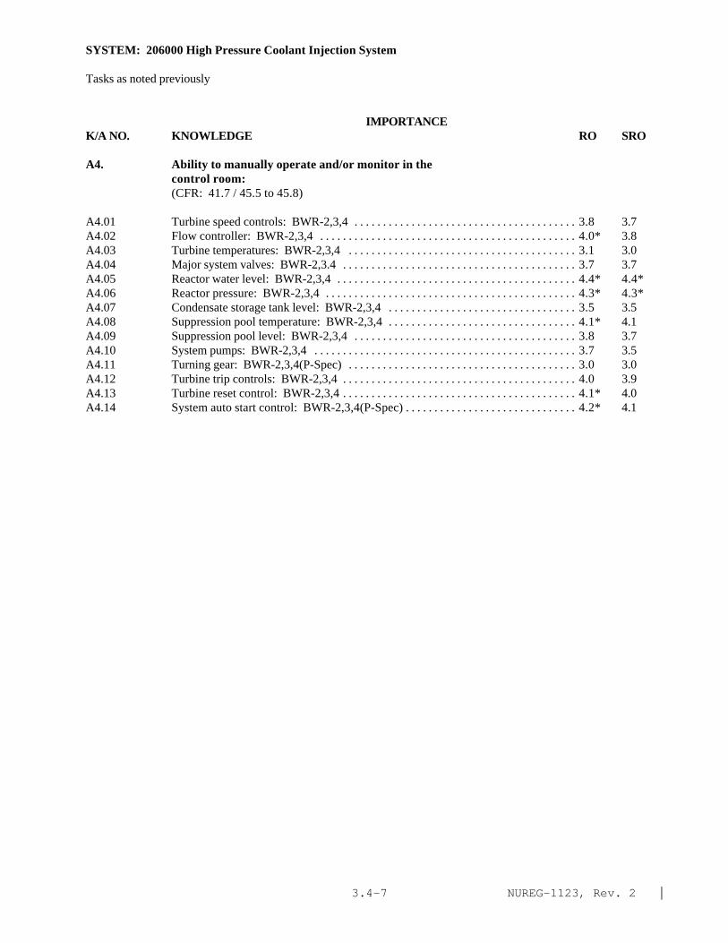
NUREG-1123, Rev. 2 |3.4-7
SYSTEM: 206000 High Pressure Coolant Injection System
Tasks as noted previously
IMPORTANCE K/A NO. KNOWLEDGE RO SRO
A4. Ability to manually operate and/or monitor in thecontrol room:(CFR: 41.7 / 45.5 to 45.8)
A4.01 Turbine speed controls: BWR-2,3,4 . . . . . . . . . . . . . . . . . . . . . . . . . . . . . . . . . . . . . . . 3.8 3.7A4.02 Flow controller: BWR-2,3,4 . . . . . . . . . . . . . . . . . . . . . . . . . . . . . . . . . . . . . . . . . . . . . 4.0* 3.8A4.03 Turbine temperatures: BWR-2,3,4 . . . . . . . . . . . . . . . . . . . . . . . . . . . . . . . . . . . . . . . . 3.1 3.0A4.04 Major system valves: BWR-2,3.4 . . . . . . . . . . . . . . . . . . . . . . . . . . . . . . . . . . . . . . . . . 3.7 3.7A4.05 Reactor water level: BWR-2,3,4 . . . . . . . . . . . . . . . . . . . . . . . . . . . . . . . . . . . . . . . . . . 4.4* 4.4*A4.06 Reactor pressure: BWR-2,3,4 . . . . . . . . . . . . . . . . . . . . . . . . . . . . . . . . . . . . . . . . . . . . 4.3* 4.3*A4.07 Condensate storage tank level: BWR-2,3,4 . . . . . . . . . . . . . . . . . . . . . . . . . . . . . . . . . 3.5 3.5A4.08 Suppression pool temperature: BWR-2,3,4 . . . . . . . . . . . . . . . . . . . . . . . . . . . . . . . . . 4.1* 4.1A4.09 Suppression pool level: BWR-2,3,4 . . . . . . . . . . . . . . . . . . . . . . . . . . . . . . . . . . . . . . . 3.8 3.7A4.10 System pumps: BWR-2,3,4 . . . . . . . . . . . . . . . . . . . . . . . . . . . . . . . . . . . . . . . . . . . . . . 3.7 3.5A4.11 Turning gear: BWR-2,3,4(P-Spec) . . . . . . . . . . . . . . . . . . . . . . . . . . . . . . . . . . . . . . . . 3.0 3.0A4.12 Turbine trip controls: BWR-2,3,4 . . . . . . . . . . . . . . . . . . . . . . . . . . . . . . . . . . . . . . . . . 4.0 3.9A4.13 Turbine reset control: BWR-2,3,4 . . . . . . . . . . . . . . . . . . . . . . . . . . . . . . . . . . . . . . . . . 4.1* 4.0A4.14 System auto start control: BWR-2,3,4(P-Spec) . . . . . . . . . . . . . . . . . . . . . . . . . . . . . . 4.2* 4.1

NUREG-1123, Rev. 2 |3.4-8
SYSTEM: 209002 High Pressure Core Spray System (HPCS)
TASK: Perform lineups on the core spray systemPlace core spray (CS) system in standby readinessMonitor automatic operation of core spray systemShutdown core spray cooling systemPerform core spray simulated automatic actuation testPerform core spray pump operability testPerform core spray system inop testConduct core spray - cold shutdown valve testing
IMPORTANCE K/A NO. KNOWLEDGE RO SRO
K1. Knowledge of the physical connections and/or cause-effect relationships between HIGH PRESSURE CORE SPRAYSYSTEM (HPCS) and the following:(CFR: 41.2 to 41.9 / 45.7 to 45.8)
K1.01 Condensate transfer and storage system: BWR-5,6 . . . . . . . . . . . . . . . . . . . . . . . . . . . 3.4 3.4K1.02 Suppression Pool: BWR-5,6 . . . . . . . . . . . . . . . . . . . . . . . . . . . . . . . . . . . . . . . . . . . . . 3.5 3.5K1.03 Water leg (jockey) pump: BWR-5,6 . . . . . . . . . . . . . . . . . . . . . . . . . . . . . . . . . . . . . . . 3.0 3.0K1.04 HPCS diesel generator: BWR-5,6 . . . . . . . . . . . . . . . . . . . . . . . . . . . . . . . . . . . . . . . . . 3.8 3.8K1.05 Standby liquid control system: Plant-Specific . . . . . . . . . . . . . . . . . . . . . . . . . . . . . . . 2.8 2.8K1.05 Suppression pool cleanup system: BWR-5,6 . . . . . . . . . . . . . . . . . . . . . . . . . . . . . . . . 2.0* 2.0K1.07 ECCS room coolers: BWR-5,6 . . . . . . . . . . . . . . . . . . . . . . . . . . . . . . . . . . . . . . . . . . . 2.4 2.4K1.08 Component cooling water systems: BWR-5,6 . . . . . . . . . . . . . . . . . . . . . . . . . . . . . . . 2.4 2.6K1.09 Leak detection: BWR-5,6 . . . . . . . . . . . . . . . . . . . . . . . . . . . . . . . . . . . . . . . . . . . . . . . . 2.5 2.5K1.10 Suppression pool suction strainers: BWR-5,6 . . . . . . . . . . . . . . . . . . . . . . . . . . . . . . . 2.1* 2.1K1.11 Adequate core cooling: BWR-5,6 . . . . . . . . . . . . . . . . . . . . . . . . . . . . . . . . . . . . . . . . . 3.8 4.0Kl.12 Reactor vessel: BWR-5,6 . . . . . . . . . . . . . . . . . . . . . . . . . . . . . . . . . . . . . . . . . . . . . . . . 3.4 3.6K1.13 Instrument nitrogen: BWR-5,6 . . . . . . . . . . . . . . . . . . . . . . . . . . . . . . . . . . . . . . . . . . . 2.7 2.7K1.14 Plant air systems: BWR-5,6 . . . . . . . . . . . . . . . . . . . . . . . . . . . . . . . . . . . . . . . . . . . . . . 2.6 2.6
K2. Knowledge of electrical power supplies to thefollowing:(CFR: 41.7)
K2.01 Pump electrical power: BWR-5,6 . . . . . . . . . . . . . . . . . . . . . . . . . . . . . . . . . . . . . . . . . 3.2 3.3K2.02 Valve electrical power: BWR-5,6 . . . . . . . . . . . . . . . . . . . . . . . . . . . . . . . . . . . . . . . . . 2.8 2.9K2.03 Initiation logic: BWR-5,6 . . . . . . . . . . . . . . . . . . . . . . . . . . . . . . . . . . . . . . . . . . . . . . . . 2.8 2.9
K3. Knowledge of the effect that a loss or malfunction ofthe HIGH PRESSURE CORE SPRAY SYSTEM (HPCS) will haveon following:(CFR: 41.7 / 45.4)
K3.01 Reactor water level: BWR-5,6 . . . . . . . . . . . . . . . . . . . . . . . . . . . . . . . . . . . . . . . . . . . . 3.9 3.9K3.02 Standby liquid control system: Plant-Specific . . . . . . . . . . . . . . . . . . . . . . . . . . . . . . . 3.3 3.3K3.03 Adequate core cooling: BWR-5,6 . . . . . . . . . . . . . . . . . . . . . . . . . . . . . . . . . . . . . . . . . 3.9 4.1

NUREG-1123, Rev. 2 |3.4-9
SYSTEM: 209002 High Pressure Core Spray System (HPCS)
IMPORTANCE K/A NO. KNOWLEDGE RO SRO
K4. Knowledge of HIGH PRESSURE CORE SPRAY SYSTEM (HPCS)design feature(s) and/or interlocks which provide forthe following:(CFR: 41.7)
K4.01 Prevents water hammer: BWR-5,6 . . . . . . . . . . . . . . . . . . . . . . . . . . . . . . . . . . . . . . . . 2.9 3.0K4.02 Prevents over filling reactor vessel: Plant-Specific. . . . . . . . . . . . . . . . . . . . . . . . . . . 3.4 3.5K4.03 Prevents pump over heating: BWR-5,6 . . . . . . . . . . . . . . . . . . . . . . . . . . . . . . . . . . . . . 2.3* 2.4K4.04 Testable check valve operation: BWR-5,6 . . . . . . . . . . . . . . . . . . . . . . . . . . . . . . . . . . 2.3* 2.3*K4.05 Motor operated valve operation: BWR-5,6 . . . . . . . . . . . . . . . . . . . . . . . . . . . . . . . . . 2.4 2.4K4.06 Centrifugal pump operation: BWR-5,6 . . . . . . . . . . . . . . . . . . . . . . . . . . . . . . . . . . . . . 2.3* 2.4*K4.07 Override of reactor water level interlock: Plant-
Specific . . . . . . . . . . . . . . . . . . . . . . . . . . . . . . . . . . . . . . . . . . . . . . . . . . . . . . . . . . . . . . . 3.5 3.7
K5. Knowledge of the operational implications of thefollowing concepts as they apply to HIGH PRESSURE CORESPRAY SYSTEM (HPCS):(CFR: 41.5 / 45.3)
K5.01 Indications of pump cavitation: BWR-5,6 . . . . . . . . . . . . . . . . . . . . . . . . . . . . . . . . . . . 2.5 2.8K5.02 Heat removal (transfer) mechanism: BWR-5,6 . . . . . . . . . . . . . . . . . . . . . . . . . . . . . . 2.6 2.7K5.03 System venting: BWR-5,6 . . . . . . . . . . . . . . . . . . . . . . . . . . . . . . . . . . . . . . . . . . . . . . . 2.4 2.4K5.04 Adequate core cooling: BWR-5,6 . . . . . . . . . . . . . . . . . . . . . . . . . . . . . . . . . . . . . . . . . 3.8 4.0
K6. Knowledge of the effect that a loss or malfunction ofthe following will have on the HIGH PRESSURE CORESPRAY SYSTEM (HPCS):(CFR: 41.7 / 45.7)
K6.01 Electrical power: BWR-5,6 . . . . . . . . . . . . . . . . . . . . . . . . . . . . . . . . . . . . . . . . . . . . . . 3.6 2.6K6.02 Condensate storage tank water level: BWR-5,6 . . . . . . . . . . . . . . . . . . . . . . . . . . . . . . 3.4 3.4K6.03 Component cooling water systems: BWR-5,6 . . . . . . . . . . . . . . . . . . . . . . . . . . . . . . . 2.5 2.6K6.04 Suppression pool suction strainer: BWR-5,6 . . . . . . . . . . . . . . . . . . . . . . . . . . . . . . . . 2.5 2.5
ABILITY
A1. Ability to predict and/or monitor changes inparameters associated with operating the HIGH PRESSURECORE SPRAY SYSTEM (HPCS) controls including:(CFR: 41.5 / 45.5)
A1.01 HPCS flow: BWR-5,6 . . . . . . . . . . . . . . . . . . . . . . . . . . . . . . . . . . . . . . . . . . . . . . . . . . . 3.6 3.7A1.02 HPCS pressure: BWR-5,6 . . . . . . . . . . . . . . . . . . . . . . . . . . . . . . . . . . . . . . . . . . . . . . . 3.4 3.6A1.03 Reactor water level: BWR-5,6 . . . . . . . . . . . . . . . . . . . . . . . . . . . . . . . . . . . . . . . . . . . . 3.7 3.7A1.04 Reactor pressure: BWR-5,6 . . . . . . . . . . . . . . . . . . . . . . . . . . . . . . . . . . . . . . . . . . . . . . 3.3 3.3A1.05 Suppression pool water level: BWR-5,6 . . . . . . . . . . . . . . . . . . . . . . . . . . . . . . . . . . . . 3.3 3.4A1.06 Motor amps: BWR-5,6 . . . . . . . . . . . . . . . . . . . . . . . . . . . . . . . . . . . . . . . . . . . . . . . . . . 1.9* 2.3*A1.07 Diesel loading: BWR-5,6 . . . . . . . . . . . . . . . . . . . . . . . . . . . . . . . . . . . . . . . . . . . . . . . . 2.5* 2.8A1.08 System lineup: BWR-5,6 . . . . . . . . . . . . . . . . . . . . . . . . . . . . . . . . . . . . . . . . . . . . . . . . 3.1 3.3

NUREG-1123, Rev. 2 |3.4-10
SYSTEM: 209002 High Pressure Core Spray System (HPCS)
Tasks as noted previously
IMPORTANCE K/A NO. KNOWLEDGE RO SRO
A1.09 Condensate storage tank level: BWR-5,6 . . . . . . . . . . . . . . . . . . . . . . . . . . . . . . . . . . . 2.6 2.8
A2. Ability to (a) predict the impacts of the following onthe HIGH PRESSURE CORE SPRAY SYSTEM (HPCS) ; and (b)based on those predictions, use procedures to correct,control, or mitigate the consequences of thoseabnormal conditions or operations:(CFR: 41.5 / 45.6)
A2.01 System initiation: BWR-5,6 . . . . . . . . . . . . . . . . . . . . . . . . . . . . . . . . . . . . . . . . . . . . . . . 3.8 3.8A2.02 Pump trips: BWR-5,6 . . . . . . . . . . . . . . . . . . . . . . . . . . . . . . . . . . . . . . . . . . . . . . . . . . . . 3.6 3.7A2.03 Valve closures: BWR-5,6 . . . . . . . . . . . . . . . . . . . . . . . . . . . . . . . . . . . . . . . . . . . . . . . . . 3.2 3.4A2.04 A.C. electrical failure: BWR-5,6 . . . . . . . . . . . . . . . . . . . . . . . . . . . . . . . . . . . . . . . . . . . 3.1 3.2A2.05 D.C. electrical failure: BWR-5,6 . . . . . . . . . . . . . . . . . . . . . . . . . . . . . . . . . . . . . . . . . . . 2.8 2.9A2.06 Core spray line break: BWR-5,6 . . . . . . . . . . . . . . . . . . . . . . . . . . . . . . . . . . . . . . . . . . . 3.4 3.6A2.07 Pump seal failure: BWR-5,6 . . . . . . . . . . . . . . . . . . . . . . . . . . . . . . . . . . . . . . . . . . . . . . 2.6 3.0A2.08 Inadequate system flow: BWR-5,6 . . . . . . . . . . . . . . . . . . . . . . . . . . . . . . . . . . . . . . . . . 3.1 3.2A2.09 Loss of room cooling: BWR-5,6 . . . . . . . . . . . . . . . . . . . . . . . . . . . . . . . . . . . . . . . . . . . 2.4 2.6A2.10 Valve openings: BWR-5,6 . . . . . . . . . . . . . . . . . . . . . . . . . . . . . . . . . . . . . . . . . . . . . . . . 2.7 3.0A2.11 Low suppression pool level: BWR-5,6 . . . . . . . . . . . . . . . . . . . . . . . . . . . . . . . . . . . . . 3.3 3.5A2.12 High suppression pool level BWR-5,6 . . . . . . . . . . . . . . . . . . . . . . . . . . . . . . . . . . . . . . . 3.3 3.5A2.13 Low condensate storage tank level BWR-5,6 . . . . . . . . . . . . . . . . . . . . . . . . . . . . . . . . . 3.4 3.5A2.14 High suppression pool temperature: BWR-5,6 . . . . . . . . . . . . . . . . . . . . . . . . . . . . . . . 3.0 3.3A2.15 Clogged suppression pool suction strainers: BWR-5,6. . . . . . . . . . . . . . . . . . . . . . . . . 2.4 2.6
A3. Ability to monitor automatic operations of the HIGHPRESSURE CORE SPRAY SYSTEM (HPCS) including:(CFR: 41.7 / 45.7)
A3.01 Valve operation: BWR-5,6 . . . . . . . . . . . . . . . . . . . . . . . . . . . . . . . . . . . . . . . . . . . . . . . . 3.3 3.3A3.02 Pump start: BWR-5,6 . . . . . . . . . . . . . . . . . . . . . . . . . . . . . . . . . . . . . . . . . . . . . . . . . . . . 3.8 3.8A3.03 System pressure: BWR-5,6 . . . . . . . . . . . . . . . . . . . . . . . . . . . . . . . . . . . . . . . . . . . . . . . 3.6 3.6A3.04 System flow: BWR-5,6 . . . . . . . . . . . . . . . . . . . . . . . . . . . . . . . . . . . . . . . . . . . . . . . . . . . 3.7 3.7A3.05 Reactor water level BWR-5,6 . . . . . . . . . . . . . . . . . . . . . . . . . . . . . . . . . . . . . . . . . . . . . . 3.7 3.7A3.06 Lights and alarms: BWR-5,6 . . . . . . . . . . . . . . . . . . . . . . . . . . . . . . . . . . . . . . . . . . . . . . 2.8 2.8
A4. Ability to manually operate and/or monitor in thecontrol room:(CFR: 41.7 / 45.5 to 45.8)
A4.01 HPCS pump: BWR-5,6 . . . . . . . . . . . . . . . . . . . . . . . . . . . . . . . . . . . . . . . . . . . . . . . . . . . 3.7 3.7A4.02 Suction valves: BWR-5,6 . . . . . . . . . . . . . . . . . . . . . . . . . . . . . . . . . . . . . . . . . . . . . . . . . 3.6 3.6A4.03 Injection valve: BWR-5,6 . . . . . . . . . . . . . . . . . . . . . . . . . . . . . . . . . . . . . . . . . . . . . . . . . 3.8 3.8A4.04 Minimum flow valve: BWR-5,6 . . . . . . . . . . . . . . . . . . . . . . . . . . . . . . . . . . . . . . . . . . . . 3.1 3.1A4.05 Manual Initiation controls: BWR-5,6 . . . . . . . . . . . . . . . . . . . . . . . . . . . . . . . . . . . . . . . 3.8 3.8

NUREG-1123, Rev. 2 |3.4-11
SYSTEM: 209002 High Pressure Core Spray System (HPCS)
Tasks as noted previously
IMPORTANCE K/A NO. ABILITY RO SRO
A4.06 Testable check valve: BWR-5,6. . . . . . . . . . . . . . . . . . . . . . . . . . . . . . . . . . . . . . . . . . . . 2.6 2.6A4.07 Line fill pump: BWR-5,6 . . . . . . . . . . . . . . . . . . . . . . . . . . . . . . . . . . . . . . . . . . . . . . . . . 2.8 2.8A4.08 Reactor water level: BWR-5,6 . . . . . . . . . . . . . . . . . . . . . . . . . . . . . . . . . . . . . . . . . . . . . 3.6 3.7A4.09 Suppression pool level: BWR-5,6 . . . . . . . . . . . . . . . . . . . . . . . . . . . . . . . . . . . . . . . . . 3.4 3.5A4.10 Reactor pressure: BWR-5,6 . . . . . . . . . . . . . . . . . . . . . . . . . . . . . . . . . . . . . . . . . . . . . . . 3.3 3.3A4.11 System flow: BWR-5,6 . . . . . . . . . . . . . . . . . . . . . . . . . . . . . . . . . . . . . . . . . . . . . . . . . . . 3.8 3.8A4.12 System pressure: BWR-5,6 . . . . . . . . . . . . . . . . . . . . . . . . . . . . . . . . . . . . . . . . . . . . . . . 3.4 3.4A4.13 Lights and alarms: BWR-5,6 . . . . . . . . . . . . . . . . . . . . . . . . . . . . . . . . . . . . . . . . . . . . . . 2.6 2.6A4.14 Test return valve: BWR-5,6 . . . . . . . . . . . . . . . . . . . . . . . . . . . . . . . . . . . . . . . . . . . . . . . 3.0 3.0A4.15 Initiation reset: BWR-5,6 . . . . . . . . . . . . . . . . . . . . . . . . . . . . . . . . . . . . . . . . . . . . . . . . . 3.6 3.6

NUREG-1123, Rev. 2 |3.4-12
SYSTEM: 207000 Isolation (Emergency) Condenser
TASK: Perform lineups on the isolation condenser systemFill and add makeup to the isolation condenser systemPlace the isolation condenser (Iso-Cond) in standbyPlace the isolation condenser system in service from a standby readiness conditionRemove the isolation condenser system from service
IMPORTANCE K/A NO. KNOWLEDGE RO SRO
K1. Knowledge of the physical connections and/or cause-effect relationships between ISOLATION (EMERGENCY)CONDENSER and the following:(CFR: 41.2 to 41.9 / 45.7 to 45.8)
K1.01 Reactor vessel: BWR-2,3 . . . . . . . . . . . . . . . . . . . . . . . . . . . . . . . . . . . . . . . . . . . . . . . 3.8 4.0K1.02 Reactor pressure: BWR-2,3 . . . . . . . . . . . . . . . . . . . . . . . . . . . . . . . . . . . . . . . . . . . . . 4.0 4.2K1.03 Reactor water level: BWR-2,3 . . . . . . . . . . . . . . . . . . . . . . . . . . . . . . . . . . . . . . . . . . . 3.7 3.8K1.04 Condensate transfer system: BWR-2,3 . . . . . . . . . . . . . . . . . . . . . . . . . . . . . . . . . . . . 3.5 3.8K1.05 Demineralized water system: BWR-2,3(P-Spec) . . . . . . . . . . . . . . . . . . . . . . . . . . . . 3.4 3.6K1.06 Fire protection/service water: BWR-2,3 . . . . . . . . . . . . . . . . . . . . . . . . . . . . . . . . . . . 3.3* 3.7K1.07 LPCI: BWR-2,3(P-Spec) . . . . . . . . . . . . . . . . . . . . . . . . . . . . . . . . . . . . . . . . . . . . . . . . 3.0* 3.3*K1.08 Recirculation system: BWR-2,3 . . . . . . . . . . . . . . . . . . . . . . . . . . . . . . . . . . . . . . . . . . 3.0 3.2Kl.09 Main steam system: BWR-2,3. . . . . . . . . . . . . . . . . . . . . . . . . . . . . . . . . . . . . . . . . . . . 3.0 3.2K1.10 Plant air systems: BWR-2,3 . . . . . . . . . . . . . . . . . . . . . . . . . . . . . . . . . . . . . . . . . . . . . 3.0* 3.2K1.11 Primary containment isolation system: BWR-2,3 . . . . . . . . . . . . . . . . . . . . . . . . . . . 3.4 3.6
K2. Knowledge of electrical power supplies to thefollowing:(CFR: 41.7)
K2.01 Motor operated valves: BWR-2,3 . . . . . . . . . . . . . . . . . . . . . . . . . . . . . . . . . . . . . . . . . 3.6 3.8K2.02 Initiation logic: BWR-2,3 . . . . . . . . . . . . . . . . . . . . . . . . . . . . . . . . . . . . . . . . . . . . . . . 3.5 3.7
K3. Knowledge of the effect that a loss or malfunction ofthe ISOLATION (EMERGENCY) CONDENSER will have onfollowing:(CFR: 41.7 / 45.4)
K3.01 Reactor pressure control during conditions in whichthe reactor vessel is isolated: BWR-2,3 . . . . . . . . . . . . . . . . . . . . . . . . . . . . . . . . . . . 4.2* 4.3*
K3.02 †Reactor water level (EPG's address the isolationcondenser as a water source): BWR-2,3 . . . . . . . . . . . . . . . . . . . . . . . . . . . . . . . . . . . 3.8* 4.0*
K4. Knowledge of ISOLATION (EMERGENCY) CONDENSER designfeature(s) and/or interlocks which provide for thefollowing:(CFR: 41.7)
K4.01 Isolation of the system in the event of a line break:BWR2,3 . . . . . . . . . . . . . . . . . . . . . . . . . . . . . . . . . . . . . . . . . . . . . . . . . . . . . . . . . . . . . . 4.3* 4.5*
K4.02 Automatic initiation: BWR-2,3 . . . . . . . . . . . . . . . . . . . . . . . . . . . . . . . . . . . . . . . . . . . 4.2* 4.2

NUREG-1123, Rev. 2 |3.4-13
SYSTEM: 207000 Isolation (Emergency) Condenser
Tasks as noted previously
IMPORTANCE K/A NO. KNOWLEDGE RO SRO
K4.03 Filling of the system: BWR-2,3 . . . . . . . . . . . . . . . . . . . . . . . . . . . . . . . . . . . . . . . . . . 3.3 3.5K4.04 Steam and condensate flow indication: BWR-2,3 . . . . . . . . . . . . . . . . . . . . . . . . . . . . 3.2 3.4K4.05 Detection of a tube bundle leak: BWR-2,3 . . . . . . . . . . . . . . . . . . . . . . . . . . . . . . . . . 4.0* 4.2K4.06 Throttling of system flow: BWR-2,3 . . . . . . . . . . . . . . . . . . . . . . . . . . . . . . . . . . . . . . 3.8* 4.0K4.07 Manual operation of the system: BWR-2,3 . . . . . . . . . . . . . . . . . . . . . . . . . . . . . . . . . 3.8* 4.0K4.08 Protection against incomplete steam condensation
(condensate outlet valve does not fully open): BWR-2,3,(P-Spec) . . . . . . . . . . . . . . . . . . . . . . . . . . . . . . . . . . . . . . . . . . . . . . . . . . . . . . . . . . . 3.4 3.6
K5. Knowledge of the operational implications of thefollowing concepts as they apply to ISOLATION(EMERGENCY) CONDENSER :(CFR: 41.5 / 45.3)
K5.01 Flow measurement across an elbow using differentialpressure: BWR-2,3 . . . . . . . . . . . . . . . . . . . . . . . . . . . . . . . . . . . . . . . . . . . . . . . . . . . . . 2.6* 3.0*
K5.02 Heat exchanger operation: BWR-2,3 . . . . . . . . . . . . . . . . . . . . . . . . . . . . . . . . . . . . . . 3.0 3.3K5.03 Heat transfer: BWR-2,3 . . . . . . . . . . . . . . . . . . . . . . . . . . . . . . . . . . . . . . . . . . . . . . . . . 2.7 3.0K5.04 Latent heat of vaporization: BWR-2,3 . . . . . . . . . . . . . . . . . . . . . . . . . . . . . . . . . . . . . . 2.3* 2.7*K5.05 Saturated steam: BWR-2,3 . . . . . . . . . . . . . . . . . . . . . . . . . . . . . . . . . . . . . . . . . . . . . . . 2.5* 2.7K5.06 Saturated liquid: BWR-2,3 . . . . . . . . . . . . . . . . . . . . . . . . . . . . . . . . . . . . . . . . . . . . . . 2.5* 2.7K5.07 Temperature sensing: BWR-2,3 . . . . . . . . . . . . . . . . . . . . . . . . . . . . . . . . . . . . . . . . . . . 2.7* 2.8K5.08 Level indicator operation: BWR-2,3 . . . . . . . . . . . . . . . . . . . . . . . . . . . . . . . . . . . . . . . 2.8* 3.0K5.09 Cooldown rate: BWR-2,3 . . . . . . . . . . . . . . . . . . . . . . . . . . . . . . . . . . . . . . . . . . . . . . . . 3.7 4.0K5.10 System venting: BWR-2,3 . . . . . . . . . . . . . . . . . . . . . . . . . . . . . . . . . . . . . . . . . . . . . . . 3.0 3.2
K6. Knowledge of the effect that a loss or malfunction ofthe following will have on the ISOLATION (EMERGENCY)CONDENSER :(CFR: 41.7 / 45.7)
K6.01 Demineralized water system: BWR-2,3(P-Spec) . . . . . . . . . . . . . . . . . . . . . . . . . . . . 3.3 3.7K6.02 Fire protection/service water system: BWR-2,3 . . . . . . . . . . . . . . . . . . . . . . . . . . . . 3.5 3.7K6.03 Condensate transfer system: BWR-2,3 . . . . . . . . . . . . . . . . . . . . . . . . . . . . . . . . . . . . 3.5 3.8K6.04 Plant air systems: BWR-2,3 . . . . . . . . . . . . . . . . . . . . . . . . . . . . . . . . . . . . . . . . . . . . . 3.2* 3.3*K6.05 Primary containment isolation system: BWR-2,3 . . . . . . . . . . . . . . . . . . . . . . . . . . . 3.6 3.8K6.06 Recirculation system: BWR-2,3 . . . . . . . . . . . . . . . . . . . . . . . . . . . . . . . . . . . . . . . . . . 3.0 3.2K6.07 A.C. power: BWR-2,3 . . . . . . . . . . . . . . . . . . . . . . . . . . . . . . . . . . . . . . . . . . . . . . . . . . 3.0* 3.2K6.08 D.C. power: BWR-2,3 . . . . . . . . . . . . . . . . . . . . . . . . . . . . . . . . . . . . . . . . . . . . . . . . . . 3.5 3.7

NUREG-1123, Rev. 2 |3.4-14
SYSTEM: 207000 Isolation (Emergency) Condenser
Tasks as noted previously
IMPORTANCE K/A NO. KNOWLEDGE RO SRO
ABILITY
A1. Ability to predict and/or monitor changes inparameters associated with operating the ISOLATION(EMERGENCY) CONDENSER controls including:(CFR: 41.5 / 45.5)
A1.01 Isolation condenser level: BWR-2,3 . . . . . . . . . . . . . . . . . . . . . . . . . . . . . . . . . . . . . . 3.7 3.8A1.02 Shell side water temperature: BWR-2,3 . . . . . . . . . . . . . . . . . . . . . . . . . . . . . . . . . . . 3.2 3.4A1.03 Steam flow: BWR-2,3 . . . . . . . . . . . . . . . . . . . . . . . . . . . . . . . . . . . . . . . . . . . . . . . . . . . 3.3* 3.5|A1.04 Condensate flow: BWR-2,3(P-Spec) . . . . . . . . . . . . . . . . . . . . . . . . . . . . . . . . . . . . . . 3.3 3.5A1.05 Reactor pressure: BWR-2,3 . . . . . . . . . . . . . . . . . . . . . . . . . . . . . . . . . . . . . . . . . . . . . . 4.0* 4.2A1.06 Reactor water level: BWR-2,3 . . . . . . . . . . . . . . . . . . . . . . . . . . . . . . . . . . . . . . . . . . . . 3.5 3.7A1.07 Vent radiation level: BWR-2,3 . . . . . . . . . . . . . . . . . . . . . . . . . . . . . . . . . . . . . . . . . . . . 3.5 3.7A1.08 Cooldown rate: BWR-2,3 . . . . . . . . . . . . . . . . . . . . . . . . . . . . . . . . . . . . . . . . . . . . . . . . 3.7 4.0A1.09 Valve operations: BWR-2,3 . . . . . . . . . . . . . . . . . . . . . . . . . . . . . . . . . . . . . . . . . . . . . . 3.7 3.7A1.10 Primary side temperature: BWR-2,3 . . . . . . . . . . . . . . . . . . . . . . . . . . . . . . . . . . . . . . . 3.2 3.4
A2. Ability to (a) predict the impacts of the following onthe ISOLATION (EMERGENCY) CONDENSER ; and (b) based onthose predictions, use procedures to correct, control,or mitigate the consequences of those abnormalconditions or operations:(CFR: 41.5 / 45.6)
A2.01 Tube bundle leak: BWR-2,3 . . . . . . . . . . . . . . . . . . . . . . . . . . . . . . . . . . . . . . . . . . . . . . 4.2* 4.5*|A2.02 †High vent radiation: BWR-2,3 . . . . . . . . . . . . . . . . . . . . . . . . . . . . . . . . . . . . . . . . . . . 4.3* 4.7*|A2.03 PCIS signal resulting in system isolation: BWR-2,3 . . . . . . . . . . . . . . . . . . . . . . . . . . 3.8* 4.0A2.04 Inadequate system flow: BWR-2,3 . . . . . . . . . . . . . . . . . . . . . . . . . . . . . . . . . . . . . . . . 3.8 4.0A2.05 Insufficient shell side makeup flow: BWR-2,3 . . . . . . . . . . . . . . . . . . . . . . . . . . . . . . 4.0 4.0A2.06 Valve openings: BWR-2,3 . . . . . . . . . . . . . . . . . . . . . . . . . . . . . . . . . . . . . . . . . . . . . . . 3.3 3.3A2.07 Valve closures: BWR-2,3 . . . . . . . . . . . . . . . . . . . . . . . . . . . . . . . . . . . . . . . . . . . . . . . . 3.5 3.5A2.08 System initiation: BWR-2,3 . . . . . . . . . . . . . . . . . . . . . . . . . . . . . . . . . . . . . . . . . . . . . . 3.8* 3.8*|
A3. Ability to monitor automatic operations of theISOLATION (EMERGENCY) CONDENSER including:(CFR: 41.7 / 45.7)
A3.01 Isolation condenser level: BWR-2,3 . . . . . . . . . . . . . . . . . . . . . . . . . . . . . . . . . . . . . . . 3.5 3.7A3.02 Reactor pressure: BWR-2,3 . . . . . . . . . . . . . . . . . . . . . . . . . . . . . . . . . . . . . . . . . . . . . . 3.8 4.0A3.03 Reactor water level: BWR-2,3 . . . . . . . . . . . . . . . . . . . . . . . . . . . . . . . . . . . . . . . . . . . . 3.5 3.7A3.04 Vent radiation levels: BWR-2,3 . . . . . . . . . . . . . . . . . . . . . . . . . . . . . . . . . . . . . . . . . . . 4.0* 4.2A3.05 System lineup: BWR-2,3 . . . . . . . . . . . . . . . . . . . . . . . . . . . . . . . . . . . . . . . . . . . . . . . . 3.6 3.8A3.06 Lights and alarms: BWR-2,3 . . . . . . . . . . . . . . . . . . . . . . . . . . . . . . . . . . . . . . . . . . . . . 3.3 3.3A3.07 Primary and shell side temperatures: BWR-2,3 . . . . . . . . . . . . . . . . . . . . . . . . . . . . . . 3.2 3.3A3.08 System flow: BWR-2,3 . . . . . . . . . . . . . . . . . . . . . . . . . . . . . . . . . . . . . . . . . . . . . . . . . . 3.2 3.4

NUREG-1123, Rev. 2 |3.4-15
SYSTEM: 207000 Isolation (Emergency) Condenser
Tasks as noted previously
IMPORTANCE K/A NO. KNOWLEDGE RO SROA4. Ability to manually operate and/or monitor in the
control room:(CFR: 41.7 / 45.5 to 45.8)
A4.01 Isolation condenser level: BWR-2,3 . . . . . . . . . . . . . . . . . . . . . . . . . . . . . . . . . . . . . . . 3.7 3.8A4.02 Steam line pressure: BWR-2,3 . . . . . . . . . . . . . . . . . . . . . . . . . . . . . . . . . . . . . . . . . . . 3.2 3.3A4.03 Primary and shell side temperatures: BWR-2,3 . . . . . . . . . . . . . . . . . . . . . . . . . . . . . . 3.0 3.2A4.04 Vent line radiation levels: BWR-2,3 . . . . . . . . . . . . . . . . . . . . . . . . . . . . . . . . . . . . . . . 3.8* 4.0A4.05 Major system valves: BWR-2,3 . . . . . . . . . . . . . . . . . . . . . . . . . . . . . . . . . . . . . . . . . . . 3.5 3.7A4.06 Shell side makeup valves: BWR-2,3 . . . . . . . . . . . . . . . . . . . . . . . . . . . . . . . . . . . . . . . 3.8* 4.0A4.07 Manually initiate the isolation condenser: BWR-2,3 . . . . . . . . . . . . . . . . . . . . . . . . . 4.2* 4.3* |

NUREG-1123, Rev. 2 |3.4-16
SYSTEM: 209001 Low Pressure Core Spray System
TASK: Fill the core spray systemsPerform lineups on the core spray systemsPlace the core spray system in standby readinessMonitor automatic operation of the core spray systemShutdown the core spray cooling systemFill the reactor cavity from the condensate storage tank with the core spray systemPerform core spray pump flow rate testPerform core spray simulated automatic actuation testPerform core spray pump operability testPerform core spray subsys and low pressure coolant injection subsys discharge piping ventilationPerform core spray system inop testConduct core spray motor operated valve operability test
IMPORTANCE K/A NO. KNOWLEDGE RO SRO
K1. Knowledge of the physical connections and/or cause-effect relationships between LOW PRESSURE CORE SPRAYSYSTEM and the following:(CFR: 41.2 to 41.9 / 45.7 to 45.8)
K1.01 Condensate storage tank: Plant-Specific . . . . . . . . . . . . . . . . . . . . . . . . . . . . . . . . . . . 3.1 3.1K1.02 Torus/suppression pool . . . . . . . . . . . . . . . . . . . . . . . . . . . . . . . . . . . . . . . . . . . . . . . . . . 3.4 3.4K1.03 Keep fill system . . . . . . . . . . . . . . . . . . . . . . . . . . . . . . . . . . . . . . . . . . . . . . . . . . . . . . . 2.9 3.0K1.04 condensate transfer system . . . . . . . . . . . . . . . . . . . . . . . . . . . . . . . . . . . . . . . . . . . . . . 2.3 2.4K1.05 Automatic depressurization system . . . . . . . . . . . . . . . . . . . . . . . . . . . . . . . . . . . . . . . . 3.7 3.7K1.06 Plant air systems . . . . . . . . . . . . . . . . . . . . . . . . . . . . . . . . . . . . . . . . . . . . . . . . . . . . . . . 2.0* 2.1*K1.07 D.C. electrical power . . . . . . . . . . . . . . . . . . . . . . . . . . . . . . . . . . . . . . . . . . . . . . . . . . . 2.5 2.7K1.08 A.C. electrical power . . . . . . . . . . . . . . . . . . . . . . . . . . . . . . . . . . . . . . . . . . . . . . . . . . . 3.2 3.3K1.09 Nuclear boiler instrumentation . . . . . . . . . . . . . . . . . . . . . . . . . . . . . . . . . . . . . . . . . . . 3.2 3.4K1.10 Emergency generator . . . . . . . . . . . . . . . . . . . . . . . . . . . . . . . . . . . . . . . . . . . . . . . . . . . 3.7 3.8K1.11 Drywell coolers: Plant-Specific . . . . . . . . . . . . . . . . . . . . . . . . . . . . . . . . . . . . . . . . . . 2.4 2.6K1.12 ECCS room coolers . . . . . . . . . . . . . . . . . . . . . . . . . . . . . . . . . . . . . . . . . . . . . . . . . . . . 2.9 3.1K1.13 Leak detection . . . . . . . . . . . . . . . . . . . . . . . . . . . . . . . . . . . . . . . . . . . . . . . . . . . . . . . . . 2.8 3.0K1.14 Reactor vessel . . . . . . . . . . . . . . . . . . . . . . . . . . . . . . . . . . . . . . . . . . . . . . . . . . . . . . . . . 3.7 3.8
K2. Knowledge of electrical power supplies to thefollowing:(CFR: 41.7)
K2.01 Pump power . . . . . . . . . . . . . . . . . . . . . . . . . . . . . . . . . . . . . . . . . . . . . . . . . . . . . . . . . . . 3.0* 3.1*K2.02 Valve power . . . . . . . . . . . . . . . . . . . . . . . . . . . . . . . . . . . . . . . . . . . . . . . . . . . . . . . . . . . 2.5* 2.7*K2.03 Initiation logic . . . . . . . . . . . . . . . . . . . . . . . . . . . . . . . . . . . . . . . . . . . . . . . . . . . . . . . . . 2.9* 3.1*

NUREG-1123, Rev. 2 |3.4-17
SYSTEM: 209001 Low Pressure Core Spray System
Tasks as noted previously
IMPORTANCE K/A NO. KNOWLEDGE RO SRO
K3. Knowledge of the effect that a loss or malfunction ofthe LOW PRESSURE CORE SPRAY SYSTEM will have onfollowing:(CFR: 41.7 / 45.4)
K3.01 Reactor water level . . . . . . . . . . . . . . . . . . . . . . . . . . . . . . . . . . . . . . . . . . . . . . . . . . . . . 3.8 3.9 |K3.02 ADS logic . . . . . . . . . . . . . . . . . . . . . . . . . . . . . . . . . . . . . . . . . . . . . . . . . . . . . . . . . . . . . 3.8 3.9K3.03 Emergency generators . . . . . . . . . . . . . . . . . . . . . . . . . . . . . . . . . . . . . . . . . . . . . . . . . . 2.9 3.0K3.04 Component cooling water systems . . . . . . . . . . . . . . . . . . . . . . . . . . . . . . . . . . . . . . . . 2.1* 2.2K3.05 Drywell cooling: Plant-Specific . . . . . . . . . . . . . . . . . . . . . . . . . . . . . . . . . . . . . . . . . . 2.3 2.7
K4. Knowledge of LOW PRESSURE CORE SPRAY SYSTEM designfeature(s) and/or interlocks which provide for thefollowing:(CFR: 41.7)
K4.01 Prevention of overpressurization of core spray piping . . . . . . . . . . . . . . . . . . . . . . . . . 3.2 3.4K4.02 Prevents water hammer . . . . . . . . . . . . . . . . . . . . . . . . . . . . . . . . . . . . . . . . . . . . . . . . . . 3.0 3.2K4.03 Motor cooling . . . . . . . . . . . . . . . . . . . . . . . . . . . . . . . . . . . . . . . . . . . . . . . . . . . . . . . . . 2.4 2.5K4.04 Line break detection . . . . . . . . . . . . . . . . . . . . . . . . . . . . . . . . . . . . . . . . . . . . . . . . . . . . 3.0 3.2K4.05 Pump minimum flow . . . . . . . . . . . . . . . . . . . . . . . . . . . . . . . . . . . . . . . . . . . . . . . . . . . . 2.6 2.6K4.06 Adequate pump net positive suction head . . . . . . . . . . . . . . . . . . . . . . . . . . . . . . . . . . . 2.6 2.9K4.07 Pump operability testing . . . . . . . . . . . . . . . . . . . . . . . . . . . . . . . . . . . . . . . . . . . . . . . . . 2.8 3.0K4.08 Automatic system initiation . . . . . . . . . . . . . . . . . . . . . . . . . . . . . . . . . . . . . . . . . . . . . . 3.8 4.0K4.09 Load sequencing . . . . . . . . . . . . . . . . . . . . . . . . . . . . . . . . . . . . . . . . . . . . . . . . . . . . . . . 3.3 3.5K4.10 Testability of all operable components . . . . . . . . . . . . . . . . . . . . . . . . . . . . . . . . . . . . . 2.8 2.9
K5. Knowledge of the operational implications of thefollowing concepts as they apply to LOW PRESSURE CORESPRAY SYSTEM :(CFR: 41.5 / 45.3)
K5.01 Indications of pump cavitation . . . . . . . . . . . . . . . . . . . . . . . . . . . . . . . . . . . . . . . . . . . . 2.6 2.7K5.02 Differential pressure indication . . . . . . . . . . . . . . . . . . . . . . . . . . . . . . . . . . . . . . . . . . . 2.4 2.6K5.03 Testable check valve operation . . . . . . . . . . . . . . . . . . . . . . . . . . . . . . . . . . . . . . . . . . . . 2.3 2.4K5.04 Heat removal (transfer) mechanisms . . . . . . . . . . . . . . . . . . . . . . . . . . . . . . . . . . . . . . . 2.8 2.9K5.05 System venting . . . . . . . . . . . . . . . . . . . . . . . . . . . . . . . . . . . . . . . . . . . . . . . . . . . . . . . . . 2.5 2.5K5.06 Recirculation operation: Plant-Specific(BWR-1) . . . . . . . . . . . . . . . . . . . . . . . . . . . 3.7 4.0
K6. Knowledge of the effect that a loss or malfunction ofthe following will have on the LOW PRESSURE CORE SPRAYSYSTEM :(CFR: 41.7 / 45.7)
K6.01 A.C. power . . . . . . . . . . . . . . . . . . . . . . . . . . . . . . . . . . . . . . . . . . . . . . . . . . . . . . . . . . . . 3.4 3.4K6.02 Emergency generators . . . . . . . . . . . . . . . . . . . . . . . . . . . . . . . . . . . . . . . . . . . . . . . . . . 3.8 3.9K6.03 Torus/suppression pool water level . . . . . . . . . . . . . . . . . . . . . . . . . . . . . . . . . . . . . . . . 3.3 3.4

NUREG-1123, Rev. 2 |3.4-18
SYSTEM: 209001 Low Pressure Core Spray System
Tasks as noted previously
IMPORTANCE K/A NO. KNOWLEDGE . . . . . . . . . . . . . . . . . . . . . . . . . . . . . . . . . . . . . . . . . . . . . . . . . . . . . . . . RO SROK6.04 D.C. power . . . . . . . . . . . . . . . . . . . . . . . . . . . . . . . . . . . . . . . . . . . . . . . . . . . . . . . . . . . . 2.8 2.9K6.05 ECCS room cooler(s) . . . . . . . . . . . . . . . . . . . . . . . . . . . . . . . . . . . . . . . . . . . . . . . . . . . 2.8 2.9K6.06 Pump motor cooler(s) . . . . . . . . . . . . . . . . . . . . . . . . . . . . . . . . . . . . . . . . . . . . . . . . . . 2.4 2.4K6.07 Pump seal cooler(s) . . . . . . . . . . . . . . . . . . . . . . . . . . . . . . . . . . . . . . . . . . . . . . . . . . . . 2.3 2.3K6.08 Keep fill system . . . . . . . . . . . . . . . . . . . . . . . . . . . . . . . . . . . . . . . . . . . . . . . . . . . . . . . 2.9 3.0K6.09 Fire protection: BWR-1 . . . . . . . . . . . . . . . . . . . . . . . . . . . . . . . . . . . . . . . . . . . . . . . . 3.0* 3.3K6.10 ECCS room integrity: Plant-Specific . . . . . . . . . . . . . . . . . . . . . . . . . . . . . . . . . . . . . . 2.3 2.5K6.11 ADS . . . . . . . . . . . . . . . . . . . . . . . . . . . . . . . . . . . . . . . . . . . . . . . . . . . . . . . . . . . . . . . . . . 3.6 3.7
ABILITY
A1. Ability to predict and/or monitor changes inparameters associated with operating the LOW PRESSURECORE SPRAY SYSTEM controls including:(CFR: 41.5 / 45.5)
A1.01 Core spray flow . . . . . . . . . . . . . . . . . . . . . . . . . . . . . . . . . . . . . . . . . . . . . . . . . . . . . . . . 3.4 3.6A1.02 Core spray pressure . . . . . . . . . . . . . . . . . . . . . . . . . . . . . . . . . . . . . . . . . . . . . . . . . . . . . 3.2 3.4A1.03 Reactor water level . . . . . . . . . . . . . . . . . . . . . . . . . . . . . . . . . . . . . . . . . . . . . . . . . . . . . 3.8 3.9A1.04 Reactor pressure . . . . . . . . . . . . . . . . . . . . . . . . . . . . . . . . . . . . . . . . . . . . . . . . . . . . . . . 3.7 3.7A1.05 Torus/suppression pool water level . . . . . . . . . . . . . . . . . . . . . . . . . . . . . . . . . . . . . . . . 3.5 3.6A1.06 Motor amps . . . . . . . . . . . . . . . . . . . . . . . . . . . . . . . . . . . . . . . . . . . . . . . . . . . . . . . . . . . 2.3* 2.4A1.07 Emergency generator loading . . . . . . . . . . . . . . . . . . . . . . . . . . . . . . . . . . . . . . . . . . . . . 3.0 3.1A1.08 System lineup . . . . . . . . . . . . . . . . . . . . . . . . . . . . . . . . . . . . . . . . . . . . . . . . . . . . . . . . . . 3.3 3.2
A2. Ability to (a) predict the impacts of the following onthe LOW PRESSURE CORE SPRAY SYSTEM ; and (b) based onthose predictions, use procedures to correct, control,or mitigate the consequences of those abnormalconditions or operations:(CFR: 41.5 / 45.6)
A2.01 Pump trips . . . . . . . . . . . . . . . . . . . . . . . . . . . . . . . . . . . . . . . . . . . . . . . . . . . . . . . . . . . . 3.4 3.4A2.02 Valve closures . . . . . . . . . . . . . . . . . . . . . . . . . . . . . . . . . . . . . . . . . . . . . . . . . . . . . . . . . 3.2 3.2A2.03 A.C. failures . . . . . . . . . . . . . . . . . . . . . . . . . . . . . . . . . . . . . . . . . . . . . . . . . . . . . . . . . . . 3.4 3.6A2.04 D.C. failures . . . . . . . . . . . . . . . . . . . . . . . . . . . . . . . . . . . . . . . . . . . . . . . . . . . . . . . . . . . 2.9 3.0A2.05 Core spray line break . . . . . . . . . . . . . . . . . . . . . . . . . . . . . . . . . . . . . . . . . . . . . . . . . . . 3.3 3.6A2.06 Inadequate system flow . . . . . . . . . . . . . . . . . . . . . . . . . . . . . . . . . . . . . . . . . . . . . . . . . . 3.2 3.2A2.07 Loss of room cooling . . . . . . . . . . . . . . . . . . . . . . . . . . . . . . . . . . . . . . . . . . . . . . . . . . . 2.6 2.8A2.08 Valve openings . . . . . . . . . . . . . . . . . . . . . . . . . . . . . . . . . . . . . . . . . . . . . . . . . . . . . . . . . 3.1 3.1A2.09 Low suppression pool level . . . . . . . . . . . . . . . . . . . . . . . . . . . . . . . . . . . . . . . . . . . . . . 3.1 3.3A2.10 †High suppression pool temperature . . . . . . . . . . . . . . . . . . . . . . . . . . . . . . . . . . . . . . . 3.1 3.4A2.11 †Loss of fire protection: BWR-1 . . . . . . . . . . . . . . . . . . . . . . . . . . . . . . . . . . . . . . . . . 2.8* 3.3

NUREG-1123, Rev. 2 |3.4-19
SYSTEM: 209001 Low Pressure Core Spray System
Tasks as noted previously
IMPORTANCE K/A NO. ABILITY RO SRO
A3. Ability to monitor automatic operations of the LOWPRESSURE CORE SPRAY SYSTEM including:(CFR: 41.7 / 45.7)
A3.01 Valve operation . . . . . . . . . . . . . . . . . . . . . . . . . . . . . . . . . . . . . . . . . . . . . . . . . . . . . . . . . 3.6 3.6A3.02 Pump start . . . . . . . . . . . . . . . . . . . . . . . . . . . . . . . . . . . . . . . . . . . . . . . . . . . . . . . . . . . . . 3.8 3.7A3.03 System pressure . . . . . . . . . . . . . . . . . . . . . . . . . . . . . . . . . . . . . . . . . . . . . . . . . . . . . . . . . 3.5 3.5A3.04 System flow . . . . . . . . . . . . . . . . . . . . . . . . . . . . . . . . . . . . . . . . . . . . . . . . . . . . . . . . . . . . 3.7 3.6A3.05 Reactor water level . . . . . . . . . . . . . . . . . . . . . . . . . . . . . . . . . . . . . . . . . . . . . . . . . . . . . . 3.9 3.9A3.06 Lights and alarms . . . . . . . . . . . . . . . . . . . . . . . . . . . . . . . . . . . . . . . . . . . . . . . . . . . . . . . . 3.6 3.5
A4. Ability to manually operate and/or monitor in thecontrol room:(CFR: 41.7 / 45.5 to 45.8)
A4.01 Core spray pump . . . . . . . . . . . . . . . . . . . . . . . . . . . . . . . . . . . . . . . . . . . . . . . . . . . . . . . . 3.8 3.6A4.02 Suction valves . . . . . . . . . . . . . . . . . . . . . . . . . . . . . . . . . . . . . . . . . . . . . . . . . . . . . . . . . . 3.5 3.4A4.03 Injection valves . . . . . . . . . . . . . . . . . . . . . . . . . . . . . . . . . . . . . . . . . . . . . . . . . . . . . . . . 3.7 3.6A4.04 Minimal flow valves . . . . . . . . . . . . . . . . . . . . . . . . . . . . . . . . . . . . . . . . . . . . . . . . . . . . . 2.9 2.9A4.05 Manual initiation controls . . . . . . . . . . . . . . . . . . . . . . . . . . . . . . . . . . . . . . . . . . . . . . . 3.8 3.6A4.06 Testable check valves . . . . . . . . . . . . . . . . . . . . . . . . . . . . . . . . . . . . . . . . . . . . . . . . . . . 2.4 2.4A4.07 Fill pump . . . . . . . . . . . . . . . . . . . . . . . . . . . . . . . . . . . . . . . . . . . . . . . . . . . . . . . . . . . . . . 2.7 2.8A4.08 Reactor water level . . . . . . . . . . . . . . . . . . . . . . . . . . . . . . . . . . . . . . . . . . . . . . . . . . . . . . 3.9 3.9A4.09 Suppression pool level . . . . . . . . . . . . . . . . . . . . . . . . . . . . . . . . . . . . . . . . . . . . . . . . . . 3.6 3.5A4.10 Reactor pressure . . . . . . . . . . . . . . . . . . . . . . . . . . . . . . . . . . . . . . . . . . . . . . . . . . . . . . . . 3.9 3.8A4.11 System flow . . . . . . . . . . . . . . . . . . . . . . . . . . . . . . . . . . . . . . . . . . . . . . . . . . . . . . . . . . . 3.7 3.6A4.12 System pressure . . . . . . . . . . . . . . . . . . . . . . . . . . . . . . . . . . . . . . . . . . . . . . . . . . . . . . . . 3.6 3.5A4.13 Lights and alarms . . . . . . . . . . . . . . . . . . . . . . . . . . . . . . . . . . . . . . . . . . . . . . . . . . . . . . . 3.4 3.4A4.14 Containment level: BWR-1 . . . . . . . . . . . . . . . . . . . . . . . . . . . . . . . . . . . . . . . . . . . . . . 3.6 3.6
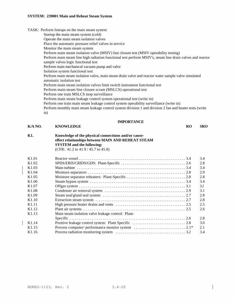
NUREG-1123, Rev. 2 |3.4-20
SYSTEM: 239001 Main and Reheat Steam System
TASK: Perform lineups on the main steam systemStartup the main steam system (cold)Operate the main steam isolation valvesPlace the automatic pressure relief valves in serviceMonitor the main steam systemPerform main steam isolation valve (MSIV) fast closure test (MSIV operability testing)Perform main steam line high radiation functional test perform MSIV's, steam line drain valves and reactorsample valves logic functional testPerform main mechanical vacuum pump and valveIsolation system functional testPerform main steam isolation valve, main steam drain valve and reactor water sample valve simulatedautomatic isolation testPerform main steam isolation valves limit switch instrument functional testPerform main steam line closure scram (MSLCS) operational testPerform one train MSLCS inop surveillancePerform main steam leakage control system operational test (write in)Perform one train main steam leakage control system operability surveillance (write in)Perform monthly main steam leakage control system division 1 and division 2 fan and heater tests (writein)
IMPORTANCE K/A NO. KNOWLEDGE RO SRO
K1. Knowledge of the physical connections and/or cause-effect relationships between MAIN AND REHEAT STEAMSYSTEM and the following:(CFR: 41.2 to 41.9 / 45.7 to 45.8)
K1.01 Reactor vessel . . . . . . . . . . . . . . . . . . . . . . . . . . . . . . . . . . . . . . . . . . . . . . . . . . . . . . . . . . 3.4 3.4K1.02 SPDS/ERlS/CRIDS/GDS: Plant-Specific . . . . . . . . . . . . . . . . . . . . . . . . . . . . . . . . . . . 2.6 2.8K1.03 Main turbine . . . . . . . . . . . . . . . . . . . . . . . . . . . . . . . . . . . . . . . . . . . . . . . . . . . . . . . . . . . 3.4 3.4|K1.04 Moisture separators . . . . . . . . . . . . . . . . . . . . . . . . . . . . . . . . . . . . . . . . . . . . . . . . . . . . . 2.8 2.9|K1.05 Moisture separator reheaters: Plant-Specific . . . . . . . . . . . . . . . . . . . . . . . . . . . . . . . . 2.8 2.8K1.06 Steam bypass system . . . . . . . . . . . . . . . . . . . . . . . . . . . . . . . . . . . . . . . . . . . . . . . . . . . . 3.4 3.4K1.07 Offgas system . . . . . . . . . . . . . . . . . . . . . . . . . . . . . . . . . . . . . . . . . . . . . . . . . . . . . . . . . . 3.1 3.lK1.08 Condenser air removal system . . . . . . . . . . . . . . . . . . . . . . . . . . . . . . . . . . . . . . . . . . . . 2.9 3.1K1.09 Steam seal/gland seal system . . . . . . . . . . . . . . . . . . . . . . . . . . . . . . . . . . . . . . . . . . . . . 2.7 2.8K1.10 Extraction steam system . . . . . . . . . . . . . . . . . . . . . . . . . . . . . . . . . . . . . . . . . . . . . . . . . 2.7 2.8K1.11 High pressure heater drains and vents . . . . . . . . . . . . . . . . . . . . . . . . . . . . . . . . . . . . . . 2.5 2.5K1.12 Plant air systems . . . . . . . . . . . . . . . . . . . . . . . . . . . . . . . . . . . . . . . . . . . . . . . . . . . . . . . . 2.5 2.6K1.13 Main steam isolation valve leakage control: Plant-
Specific . . . . . . . . . . . . . . . . . . . . . . . . . . . . . . . . . . . . . . . . . . . . . . . . . . . . . . . . . . . . . . . 2.6 2.8K1.14 Positive leakage control system: Plant Specific . . . . . . . . . . . . . . . . . . . . . . . . . . . . . 2.8 3.0|K1.15 Process computer/ performance monitor system . . . . . . . . . . . . . . . . . . . . . . . . . . . . 2.1* 2.1K1.16 Process radiation monitoring system . . . . . . . . . . . . . . . . . . . . . . . . . . . . . . . . . . . . . . 3.2 3.4
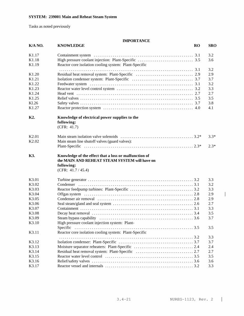
NUREG-1123, Rev. 2 |3.4-21
SYSTEM: 239001 Main and Reheat Steam System
Tasks as noted previously
IMPORTANCE K/A NO. KNOWLEDGE RO SRO
K1.17 Containment system . . . . . . . . . . . . . . . . . . . . . . . . . . . . . . . . . . . . . . . . . . . . . . . . . . . . 3.1 3.2K1.18 High pressure coolant injection: Plant-Specific . . . . . . . . . . . . . . . . . . . . . . . . . . . . . 3.5 3.6K1.19 Reactor core isolation cooling system: Plant-Specific
. . . . . . . . . . . . . . . . . . . . . . . . . . . . . . . . . . . . . . . . . . . . . . . . . . . . . . . . . . . . . . . . . . . . . . 3.1 3.2K1.20 Residual heat removal system: Plant-Specific . . . . . . . . . . . . . . . . . . . . . . . . . . . . . . 2.9 2.9K1.21 Isolation condenser system: Plant-Specific . . . . . . . . . . . . . . . . . . . . . . . . . . . . . . . . 3.7 3.7K1.22 Feedwater system . . . . . . . . . . . . . . . . . . . . . . . . . . . . . . . . . . . . . . . . . . . . . . . . . . . . . . 3.1 3.2K1.23 Reactor water level control system . . . . . . . . . . . . . . . . . . . . . . . . . . . . . . . . . . . . . . . . 3.2 3.3K1.24 Head vent . . . . . . . . . . . . . . . . . . . . . . . . . . . . . . . . . . . . . . . . . . . . . . . . . . . . . . . . . . . . . 2.7 2.7K1.25 Relief valves . . . . . . . . . . . . . . . . . . . . . . . . . . . . . . . . . . . . . . . . . . . . . . . . . . . . . . . . . . . 3.5 3.5Kl.26 Safety valves . . . . . . . . . . . . . . . . . . . . . . . . . . . . . . . . . . . . . . . . . . . . . . . . . . . . . . . . . . . 3.7 3.8K1.27 Reactor protection system . . . . . . . . . . . . . . . . . . . . . . . . . . . . . . . . . . . . . . . . . . . . . . . 4.0 4.1
K2. Knowledge of electrical power supplies to thefollowing:(CFR: 41.7)
K2.01 Main steam isolation valve solenoids . . . . . . . . . . . . . . . . . . . . . . . . . . . . . . . . . . . . . . 3.2* 3.3*K2.02 Main steam line shutoff valves (guard valves):
Plant-Specific . . . . . . . . . . . . . . . . . . . . . . . . . . . . . . . . . . . . . . . . . . . . . . . . . . . . . . . . . 2.3* 2.3*
K3. Knowledge of the effect that a loss or malfunction ofthe MAIN AND REHEAT STEAM SYSTEM will have onfollowing:(CFR: 41.7 / 45.4)
K3.01 Turbine generator . . . . . . . . . . . . . . . . . . . . . . . . . . . . . . . . . . . . . . . . . . . . . . . . . . . . . . . 3.2 3.3K3.02 Condenser . . . . . . . . . . . . . . . . . . . . . . . . . . . . . . . . . . . . . . . . . . . . . . . . . . . . . . . . . . . . 3.1 3.2K3.03 Reactor feedpump turbines: Plant-Specific . . . . . . . . . . . . . . . . . . . . . . . . . . . . . . . . . 3.2 3.3K3.04 Offgas system . . . . . . . . . . . . . . . . . . . . . . . . . . . . . . . . . . . . . . . . . . . . . . . . . . . . . . . . . 2.8 2.9 |K3.05 Condenser air removal . . . . . . . . . . . . . . . . . . . . . . . . . . . . . . . . . . . . . . . . . . . . . . . . . . 2.8 2.9K3.06 Seal steam/gland and seal system . . . . . . . . . . . . . . . . . . . . . . . . . . . . . . . . . . . . . . . . . . 2.6 2.7K3.07 Containment . . . . . . . . . . . . . . . . . . . . . . . . . . . . . . . . . . . . . . . . . . . . . . . . . . . . . . . . . . . 3.1 3.3K3.08 Decay heat removal . . . . . . . . . . . . . . . . . . . . . . . . . . . . . . . . . . . . . . . . . . . . . . . . . . . . . 3.4 3.5K3.09 Steam bypass capability . . . . . . . . . . . . . . . . . . . . . . . . . . . . . . . . . . . . . . . . . . . . . . . . . 3.6 3.7K3.10 High pressure coolant injection system: Plant-
Specific . . . . . . . . . . . . . . . . . . . . . . . . . . . . . . . . . . . . . . . . . . . . . . . . . . . . . . . . . . . . . . 3.5 3.5K3.11 Reactor core isolation cooling system: Plant-Specific
. . . . . . . . . . . . . . . . . . . . . . . . . . . . . . . . . . . . . . . . . . . . . . . . . . . . . . . . . . . . . . . . . . . . . . 3.2 3.3K3.12 Isolation condenser: Plant-Specific . . . . . . . . . . . . . . . . . . . . . . . . . . . . . . . . . . . . . . . 3.7 3.7K3.13 Moisture separator reheaters: Plant-Specific . . . . . . . . . . . . . . . . . . . . . . . . . . . . . . . 2.4 2.4K3.14 Residual heat removal system: Plant-Specific . . . . . . . . . . . . . . . . . . . . . . . . . . . . . . 2.7 2.7K3.15 Reactor water level control . . . . . . . . . . . . . . . . . . . . . . . . . . . . . . . . . . . . . . . . . . . . . . 3.5 3.5K3.16 Relief/safety valves . . . . . . . . . . . . . . . . . . . . . . . . . . . . . . . . . . . . . . . . . . . . . . . . . . . . . 3.6 3.6K3.17 Reactor vessel and internals . . . . . . . . . . . . . . . . . . . . . . . . . . . . . . . . . . . . . . . . . . . . . . 3.2 3.3

NUREG-1123, Rev. 2 |3.4-22
SYSTEM: 239001 Main and Reheat Steam System
Tasks as noted previously
IMPORTANCE K/A NO. KNOWLEDGE RO SRO
K4. Knowledge of MAIN AND REHEAT STEAM SYSTEM designfeature(s) and/or interlocks which provide for thefollowing:(CFR: 41.7)
K4.01 Automatic isolation of steam lines . . . . . . . . . . . . . . . . . . . . . . . . . . . . . . . . . . . . . . . . 3.8 3.8K4.02 Automatic isolation and opening of drain valves:
Plant-Specific . . . . . . . . . . . . . . . . . . . . . . . . . . . . . . . . . . . . . . . . . . . . . . . . . . . . . . . . . 3.1 3.2K4.03 Insures that steam released from a steam line break
will not bypass suppression pool; BWR-6 . . . . . . . . . . . . . . . . . . . . . . . . . . . . . . . . . . 3.2 3.3K4.04 Limits steam flow during a steam line rupture to 200% . . . . . . . . . . . . . . . . . . . . . . . . 3.4 3.5K4.05 Steam flow measurement . . . . . . . . . . . . . . . . . . . . . . . . . . . . . . . . . . . . . . . . . . . . . . . . 3.1 3.2K4.06 Allows for removal or prevents escape of radioactive
steam from systems that have leaky MSIV's . . . . . . . . . . . . . . . . . . . . . . . . . . . . . . . . . 3.1 3.2K4.07 Over pressure control . . . . . . . . . . . . . . . . . . . . . . . . . . . . . . . . . . . . . . . . . . . . . . . . . . . 3.7 3.7K4.08 Removal of non condensable gases from reactor head
area . . . . . . . . . . . . . . . . . . . . . . . . . . . . . . . . . . . . . . . . . . . . . . . . . . . . . . . . . . . . . . . . . . 2.5 2.6K4.09 Equalization of pressure across the MSIV's before
opening . . . . . . . . . . . . . . . . . . . . . . . . . . . . . . . . . . . . . . . . . . . . . . . . . . . . . . . . . . . . . . . 3.3 3.3K4.10 Moisture removal from steam lines prior to admitting
steam . . . . . . . . . . . . . . . . . . . . . . . . . . . . . . . . . . . . . . . . . . . . . . . . . . . . . . . . . . . . . . . . . 2.9 3.0K4.11 Positive sealing of the MSIV's when shutdown: Plant-
Specific . . . . . . . . . . . . . . . . . . . . . . . . . . . . . . . . . . . . . . . . . . . . . . . . . . . . . . . . . . . . . . 2.9 3.1
K5. Knowledge of the operational implications of thefollowing concepts as they apply to MAIN AND REHEATSTEAM SYSTEM :(CFR: 41.5 / 45.3)
K5.01 Constant enthalpy expansion through a valve . . . . . . . . . . . . . . . . . . . . . . . . . . . . . . . . 2.0* 2.2*|K5.02 Definition and causes of steam/water hammer . . . . . . . . . . . . . . . . . . . . . . . . . . . . . . . 2.9 3.1K5.03 Definition and causes of thermal stress . . . . . . . . . . . . . . . . . . . . . . . . . . . . . . . . . . . . 2.7 2.9K5.04 Definition and reason for steam blanketing of moisture
separator reheater: Plant-Specific . . . . . . . . . . . . . . . . . . . . . . . . . . . . . . . . . . . . . . . . 1.8* 1.9*|K5.05 Flow indication . . . . . . . . . . . . . . . . . . . . . . . . . . . . . . . . . . . . . . . . . . . . . . . . . . . . . . . . 2.8 2.8K5.06 Air operated MSIV's . . . . . . . . . . . . . . . . . . . . . . . . . . . . . . . . . . . . . . . . . . . . . . . . . . . . 2.8 2.9K5.07 Hydraulic operated MSIV's . . . . . . . . . . . . . . . . . . . . . . . . . . . . . . . . . . . . . . . . . . . . . . . 2.6 2.7K5.08 Solenoid operated valves . . . . . . . . . . . . . . . . . . . . . . . . . . . . . . . . . . . . . . . . . . . . . . . . 2.6 2.7K5.09 Decay heat removal . . . . . . . . . . . . . . . . . . . . . . . . . . . . . . . . . . . . . . . . . . . . . . . . . . . . . 3.4 3.5
K6. Knowledge of the effect that a loss or malfunction ofthe following will have on the MAIN AND REHEAT STEAMSYSTEM :(CFR: 41.7 / 45.7)
K6.01 Electrical power . . . . . . . . . . . . . . . . . . . . . . . . . . . . . . . . . . . . . . . . . . . . . . . . . . . . . . . 3.1 3.3K6.02 Plant air systems . . . . . . . . . . . . . . . . . . . . . . . . . . . . . . . . . . . . . . . . . . . . . . . . . . . . . . . 3.2 3.2|K6.03 Safety valve operability . . . . . . . . . . . . . . . . . . . . . . . . . . . . . . . . . . . . . . . . . . . . . . . . . . 3.6 3.6|
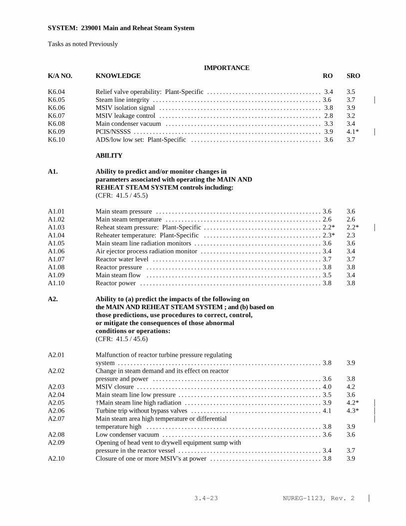
NUREG-1123, Rev. 2 |3.4-23
SYSTEM: 239001 Main and Reheat Steam System
Tasks as noted Previously
IMPORTANCE K/A NO. KNOWLEDGE RO SRO
K6.04 Relief valve operability: Plant-Specific . . . . . . . . . . . . . . . . . . . . . . . . . . . . . . . . . . . . 3.4 3.5K6.05 Steam line integrity . . . . . . . . . . . . . . . . . . . . . . . . . . . . . . . . . . . . . . . . . . . . . . . . . . . . . 3.6 3.7 |K6.06 MSIV isolation signal . . . . . . . . . . . . . . . . . . . . . . . . . . . . . . . . . . . . . . . . . . . . . . . . . . . 3.8 3.9K6.07 MSIV leakage control . . . . . . . . . . . . . . . . . . . . . . . . . . . . . . . . . . . . . . . . . . . . . . . . . . . 2.8 3.2K6.08 Main condenser vacuum . . . . . . . . . . . . . . . . . . . . . . . . . . . . . . . . . . . . . . . . . . . . . . . . . 3.3 3.4K6.09 PCIS/NSSSS . . . . . . . . . . . . . . . . . . . . . . . . . . . . . . . . . . . . . . . . . . . . . . . . . . . . . . . . . . . 3.9 4.1* |K6.10 ADS/low low set: Plant-Specific . . . . . . . . . . . . . . . . . . . . . . . . . . . . . . . . . . . . . . . . . 3.6 3.7
ABILITY
A1. Ability to predict and/or monitor changes inparameters associated with operating the MAIN ANDREHEAT STEAM SYSTEM controls including:(CFR: 41.5 / 45.5)
A1.01 Main steam pressure . . . . . . . . . . . . . . . . . . . . . . . . . . . . . . . . . . . . . . . . . . . . . . . . . . . . 3.6 3.6A1.02 Main steam temperature . . . . . . . . . . . . . . . . . . . . . . . . . . . . . . . . . . . . . . . . . . . . . . . . . 2.6 2.6A1.03 Reheat steam pressure: Plant-Specific . . . . . . . . . . . . . . . . . . . . . . . . . . . . . . . . . . . . . 2.2* 2.2* |A1.04 Reheater temperature: Plant-Specific . . . . . . . . . . . . . . . . . . . . . . . . . . . . . . . . . . . . . 2.3* 2.3A1.05 Main steam line radiation monitors . . . . . . . . . . . . . . . . . . . . . . . . . . . . . . . . . . . . . . . . 3.6 3.6A1.06 Air ejector process radiation monitor . . . . . . . . . . . . . . . . . . . . . . . . . . . . . . . . . . . . . . 3.4 3.4A1.07 Reactor water level . . . . . . . . . . . . . . . . . . . . . . . . . . . . . . . . . . . . . . . . . . . . . . . . . . . . . 3.7 3.7A1.08 Reactor pressure . . . . . . . . . . . . . . . . . . . . . . . . . . . . . . . . . . . . . . . . . . . . . . . . . . . . . . . 3.8 3.8A1.09 Main steam flow . . . . . . . . . . . . . . . . . . . . . . . . . . . . . . . . . . . . . . . . . . . . . . . . . . . . . . . 3.5 3.4A1.10 Reactor power . . . . . . . . . . . . . . . . . . . . . . . . . . . . . . . . . . . . . . . . . . . . . . . . . . . . . . . . . 3.8 3.8
A2. Ability to (a) predict the impacts of the following onthe MAIN AND REHEAT STEAM SYSTEM ; and (b) based onthose predictions, use procedures to correct, control,or mitigate the consequences of those abnormalconditions or operations:(CFR: 41.5 / 45.6)
A2.01 Malfunction of reactor turbine pressure regulatingsystem . . . . . . . . . . . . . . . . . . . . . . . . . . . . . . . . . . . . . . . . . . . . . . . . . . . . . . . . . . . . . . . . 3.8 3.9
A2.02 Change in steam demand and its effect on reactorpressure and power . . . . . . . . . . . . . . . . . . . . . . . . . . . . . . . . . . . . . . . . . . . . . . . . . . . . . 3.6 3.8
A2.03 MSIV closure . . . . . . . . . . . . . . . . . . . . . . . . . . . . . . . . . . . . . . . . . . . . . . . . . . . . . . . . . . 4.0 4.2A2.04 Main steam line low pressure . . . . . . . . . . . . . . . . . . . . . . . . . . . . . . . . . . . . . . . . . . . . . 3.5 3.6A2.05 †Main steam line high radiation . . . . . . . . . . . . . . . . . . . . . . . . . . . . . . . . . . . . . . . . . . . 3.9 4.2* |A2.06 Turbine trip without bypass valves . . . . . . . . . . . . . . . . . . . . . . . . . . . . . . . . . . . . . . . . . 4.1 4.3* |A2.07 Main steam area high temperature or differential |
temperature high . . . . . . . . . . . . . . . . . . . . . . . . . . . . . . . . . . . . . . . . . . . . . . . . . . . . . . . 3.8 3.9A2.08 Low condenser vacuum . . . . . . . . . . . . . . . . . . . . . . . . . . . . . . . . . . . . . . . . . . . . . . . . . . 3.6 3.6A2.09 Opening of head vent to drywell equipment sump with
pressure in the reactor vessel . . . . . . . . . . . . . . . . . . . . . . . . . . . . . . . . . . . . . . . . . . . . . 3.4 3.7A2.10 Closure of one or more MSIV's at power . . . . . . . . . . . . . . . . . . . . . . . . . . . . . . . . . . . 3.8 3.9

NUREG-1123, Rev. 2 |3.4-24
SYSTEM: 239001 Main and Reheat Steam System
Tasks as noted previously
IMPORTANCE K/A NO. ABILITY RO SRO
A2.11 Steam line break . . . . . . . . . . . . . . . . . . . . . . . . . . . . . . . . . . . . . . . . . . . . . . . . . . . . . . . 4.1 4.3*|A2.12 PCIS/NSSSS actuation . . . . . . . . . . . . . . . . . . . . . . . . . . . . . . . . . . . . . . . . . . . . . . . . . . . 4.2* 4.3*|A2.13 High reactor water level . . . . . . . . . . . . . . . . . . . . . . . . . . . . . . . . . . . . . . . . . . . . . . . . . 3.5 3.7A2.14 Inadvertent initiation of HPCI/HPCS/RCIC (steam
quality and steam flow): Plant-Specific . . . . . . . . . . . . . . . . . . . . . . . . . . . . . . . . . . . . 3.4 3.5
A3. Ability to monitor automatic operations of the MAINAND REHEAT STEAM SYSTEM including:(CFR: 41.7 / 45.7)
A3.01 Isolation of main steam system . . . . . . . . . . . . . . . . . . . . . . . . . . . . . . . . . . . . . . . . . . . 4.2* 4.1*A3.02 Opening and closing of drain valves as turbine load
changes: Plant-Specific . . . . . . . . . . . . . . . . . . . . . . . . . . . . . . . . . . . . . . . . . . . . . . . . . 2.9 2.9A3.03 Moisture separator reheat steam supply: Plant-
Specific . . . . . . . . . . . . . . . . . . . . . . . . . . . . . . . . . . . . . . . . . . . . . . . . . . . . . . . . . . . . . . 2.8 2.8A3.04 Isolation of moisture separator reheater: Plant-
Specific . . . . . . . . . . . . . . . . . . . . . . . . . . . . . . . . . . . . . . . . . . . . . . . . . . . . . . . . . . . . . . 2.7 2.7
A4. Ability to manually operate and/or monitor in thecontrol room:(CFR: 41.7 / 45.5 to 45.8)
A4.01 MSIV's . . . . . . . . . . . . . . . . . . . . . . . . . . . . . . . . . . . . . . . . . . . . . . . . . . . . . . . . . . . . . . . 4.2* 4.0A4.02 Maim steam line drain valves . . . . . . . . . . . . . . . . . . . . . . . . . . . . . . . . . . . . . . . . . . . . . 3.2 3.2A4.03 System flow . . . . . . . . . . . . . . . . . . . . . . . . . . . . . . . . . . . . . . . . . . . . . . . . . . . . . . . . . . . 3.5 3.5A4.04 System pressure . . . . . . . . . . . . . . . . . . . . . . . . . . . . . . . . . . . . . . . . . . . . . . . . . . . . . . . . 3.8 3.7A4.05 System temperature . . . . . . . . . . . . . . . . . . . . . . . . . . . . . . . . . . . . . . . . . . . . . . . . . . . . . 2.7 2.7A4.06 System radiation levels . . . . . . . . . . . . . . . . . . . . . . . . . . . . . . . . . . . . . . . . . . . . . . . . . . 3.6 3.8A4.07 Lights and alarms . . . . . . . . . . . . . . . . . . . . . . . . . . . . . . . . . . . . . . . . . . . . . . . . . . . . . . . 3.3 3.3A4.08 Reactor water level . . . . . . . . . . . . . . . . . . . . . . . . . . . . . . . . . . . . . . . . . . . . . . . . . . . . . 3.7 3.7A4.09 Reactor pressure . . . . . . . . . . . . . . . . . . . . . . . . . . . . . . . . . . . . . . . . . . . . . . . . . . . . . . . 3.9 3.9A4.10 Reactor power . . . . . . . . . . . . . . . . . . . . . . . . . . . . . . . . . . . . . . . . . . . . . . . . . . . . . . . . . 3.8 3.8A4.11 Alternate methods of verifying valve positions . . . . . . . . . . . . . . . . . . . . . . . . . . . . . . 3.1 3.3

NUREG-1123, Rev. 2 |3.4-25
SYSTEM: 245000 Main Turbine Generator and Auxiliary Systems
TASK: Perform lineups of the main turbine generatorStart up the turbine to rated speedPerform generator excitationOperate generator voltage regulatorSynchronize turbine generator with output grid at minimum loadIncrease load on the turbine generatorMonitor the turbine generatorSecure the amplidyne (generator in service)Return the amplidyne to serviceUnload the turbine generator electrically to minimum loadSecure generator output and excitationShut down the turbine generatorOperate the turbine turning gearOperate the turbine bearing lift oil pumps (jacking oil pumps)Synchronize turbine generator with output grid at minimum loadIncrease load on the turbine generator
IMPORTANCE K/A NO. KNOWLEDGE RO SRO
K1. Knowledge of the physical connections and/or cause-effect relationships between MAIN TURBINE GENERATORAND AUXILIARY SYSTEMS and the following:(CFR: 41.2 to 41.9 / 45.7 to 45.8)
K1.01 A. C. electrical distribution . . . . . . . . . . . . . . . . . . . . . . . . . . . . . . . . . . . . . . . . . . . . . . . 3.2 3.3K1.02 Condensate system . . . . . . . . . . . . . . . . . . . . . . . . . . . . . . . . . . . . . . . . . . . . . . . . . . . . . . 2.5 2.5K1.03 Main steam system . . . . . . . . . . . . . . . . . . . . . . . . . . . . . . . . . . . . . . . . . . . . . . . . . . . . . . 3.2 3.3K1.04 Reactor protection system . . . . . . . . . . . . . . . . . . . . . . . . . . . . . . . . . . . . . . . . . . . . . . . 3.6 3.7K1.05 Extraction steam system . . . . . . . . . . . . . . . . . . . . . . . . . . . . . . . . . . . . . . . . . . . . . . . . . 2.7 2.7K1.06 Component cooling water systems . . . . . . . . . . . . . . . . . . . . . . . . . . . . . . . . . . . . . . . . . 2.6 2.6K1.07 Plant air systems . . . . . . . . . . . . . . . . . . . . . . . . . . . . . . . . . . . . . . . . . . . . . . . . . . . . . . . . 2.5 2.5K1.08 Reactor/turbine pressure control system: Plant-
Specific . . . . . . . . . . . . . . . . . . . . . . . . . . . . . . . . . . . . . . . . . . . . . . . . . . . . . . . . . . . . . . . 3.4 3.5K1.09 D. C . electrical distribution . . . . . . . . . . . . . . . . . . . . . . . . . . . . . . . . . . . . . . . . . . . . . . 2.7 2.7
K2. Knowledge of electrical power supplies to thefollowing:(CFR: 41.7)
K2.01 Stator water cooling pumps: Plant-Specific . . . . . . . . . . . . . . . . . . . . . . . . . . . . . . . . . 2.4* 2.4K2.02 Main lubricating oil pumps . . . . . . . . . . . . . . . . . . . . . . . . . . . . . . . . . . . . . . . . . . . . . . . 2.3* 2.4*K2.03 Amplidyne: Plant-Specific . . . . . . . . . . . . . . . . . . . . . . . . . . . . . . . . . . . . . . . . . . . . . . . 1.7* 1.8*K2.04 Hydrogen seal oil pumps . . . . . . . . . . . . . . . . . . . . . . . . . . . . . . . . . . . . . . . . . . . . . . . . . 2.3* 2.3*K2.05 Air seal oil pumps: Plant-Specific . . . . . . . . . . . . . . . . . . . . . . . . . . . . . . . . . . . . . . . . . 1.7* 1.7*K2.06 Turbine supervisory instrumentation . . . . . . . . . . . . . . . . . . . . . . . . . . . . . . . . . . . . . . . 2.3 2.5

NUREG-1123, Rev. 2 |3.4-26
SYSTEM: 245000 Main Turbine Generator and Auxiliary Systems
Tasks as noted previously
IMPORTANCE K/A NO. KNOWLEDGE RO SRO
K3. Knowledge of the effect that a loss or malfunction ofthe MAIN TURBINE GENERATOR AND AUXILIARY SYSTEMS willhave on following:(CFR: 41.7 / 45.4)
K3.01 A.C. electrical distribution . . . . . . . . . . . . . . . . . . . . . . . . . . . . . . . . . . . . . . . . . . . . . . . 3.4 3.7K3.02 Reactor pressure . . . . . . . . . . . . . . . . . . . . . . . . . . . . . . . . . . . . . . . . . . . . . . . . . . . . . . . . 3.9 4.0K3.03 Reactor power . . . . . . . . . . . . . . . . . . . . . . . . . . . . . . . . . . . . . . . . . . . . . . . . . . . . . . . . . . 3.9 4.0K3.04 Reactor feedwater system (feedwater heaters) . . . . . . . . . . . . . . . . . . . . . . . . . . . . . . . 3.3 3.5K3.05 Reactor feedwater pump: Plant-Specific . . . . . . . . . . . . . . . . . . . . . . . . . . . . . . . . . . . 2.7 2.8K3.06 Condensate system . . . . . . . . . . . . . . . . . . . . . . . . . . . . . . . . . . . . . . . . . . . . . . . . . . . . . . 2.5 2.5K3.07 Reactor protection system . . . . . . . . . . . . . . . . . . . . . . . . . . . . . . . . . . . . . . . . . . . . . . . 3.6 3.7K3.08 Reactor/turbine pressure control system: Plant- Specific . . . . . . . . . . . . . . . . . . . . . . . . . . . . . . . . . . . . . . . . . . . . . . . . . . . . . . . . . . . . . . . . . . 3.7 3.8
K4. Knowledge of MAIN TURBINE GENERATOR AND AUXILIARYSYSTEMS design feature(s) and/or interlocks whichprovide for the following:(CFR: 41.7)
K4.01 Bearing lubrication . . . . . . . . . . . . . . . . . . . . . . . . . . . . . . . . . . . . . . . . . . . . . . . . . . . . . . 2.4 2.5K4.02 Generator cooling . . . . . . . . . . . . . . . . . . . . . . . . . . . . . . . . . . . . . . . . . . . . . . . . . . . . . . 2.4 2.5K4.03 Sealing to prevent hydrogen leakage . . . . . . . . . . . . . . . . . . . . . . . . . . . . . . . . . . . . . . . . 2.7 2.8K4.04 Hydrogen cooling . . . . . . . . . . . . . . . . . . . . . . . . . . . . . . . . . . . . . . . . . . . . . . . . . . . . . . . 2.4 2.5K4.05 Turbine protection . . . . . . . . . . . . . . . . . . . . . . . . . . . . . . . . . . . . . . . . . . . . . . . . . . . . . . 2.9 3.0K4.06 Generator protection . . . . . . . . . . . . . . . . . . . . . . . . . . . . . . . . . . . . . . . . . . . . . . . . . . . . 2.7 2.8K4.07 Generator voltage regulation . . . . . . . . . . . . . . . . . . . . . . . . . . . . . . . . . . . . . . . . . . . . . . 2.5 2.6K4.08 Moisture removal from turbine steam . . . . . . . . . . . . . . . . . . . . . . . . . . . . . . . . . . . . . . 2.4 2.4K4.09 Turbine control . . . . . . . . . . . . . . . . . . . . . . . . . . . . . . . . . . . . . . . . . . . . . . . . . . . . . . . . . 3.1 3.2K4.10 Extraction steam . . . . . . . . . . . . . . . . . . . . . . . . . . . . . . . . . . . . . . . . . . . . . . . . . . . . . . . . 2.6 2.7
K5. Knowledge of the operational implications of thefollowing concepts as they apply to MAIN TURBINEGENERATOR AND AUXILIARY SYSTEMS :(CFR: 41.5 / 45.3)
K5.01 Heat exchanger operation . . . . . . . . . . . . . . . . . . . . . . . . . . . . . . . . . . . . . . . . . . . . . . . . 2.3* 2.3*K5.02 Turbine operation and limitations . . . . . . . . . . . . . . . . . . . . . . . . . . . . . . . . . . . . . . . . . . 2.8 3.1K5.03 Hydraulically operated valve operation . . . . . . . . . . . . . . . . . . . . . . . . . . . . . . . . . . . . . 2.6 2.6K5.04 Turbine speed measurement . . . . . . . . . . . . . . . . . . . . . . . . . . . . . . . . . . . . . . . . . . . . . . 1.9* 2.0*K5.05 Relief valve operation . . . . . . . . . . . . . . . . . . . . . . . . . . . . . . . . . . . . . . . . . . . . . . . . . . . 2.4 2.4K5.06 Turbine shaft sealing . . . . . . . . . . . . . . . . . . . . . . . . . . . . . . . . . . . . . . . . . . . . . . . . . . . . 2.5 2.6K5.07 Generator operations and limitations . . . . . . . . . . . . . . . . . . . . . . . . . . . . . . . . . . . . . . . 2.6 2.9K5.08 Generator cooling . . . . . . . . . . . . . . . . . . . . . . . . . . . . . . . . . . . . . . . . . . . . . . . . . . . . . . 2.4 2.6

NUREG-1123, Rev. 2 |3.4-27
SYSTEM: 245000 Main Turbine Generator and Auxiliary Systems
Tasks as noted previously
IMPORTANCE K/A NO. KNOWLEDGE RO SRO
K6. Knowledge of the effect that a loss or malfunction ofthe following will have on the MAIN TURBINE GENERATORAND AUXILIARY SYSTEMS :(CFR: 41.7 / 45.7)
K6.01 Gland seal . . . . . . . . . . . . . . . . . . . . . . . . . . . . . . . . . . . . . . . . . . . . . . . . . . . . . . . . . . . . . 2.8 2.9K6.02 Reactor/turbine pressure control system: Plant-
Specific . . . . . . . . . . . . . . . . . . . . . . . . . . . . . . . . . . . . . . . . . . . . . . . . . . . . . . . . . . . . . . . 3.5 3.7K6.03 Hydrogen seal oil . . . . . . . . . . . . . . . . . . . . . . . . . . . . . . . . . . . . . . . . . . . . . . . . . . . . . . . 2.8 3.1K6.04 Hydrogen cooling . . . . . . . . . . . . . . . . . . . . . . . . . . . . . . . . . . . . . . . . . . . . . . . . . . . . . . . 2.6* 2.7K6.05 Stator water cooling . . . . . . . . . . . . . . . . . . . . . . . . . . . . . . . . . . . . . . . . . . . . . . . . . . . . . 2.9 2.9K6.06 Electrical distribution . . . . . . . . . . . . . . . . . . . . . . . . . . . . . . . . . . . . . . . . . . . . . . . . . . . 3.0 3.2K6.07 Extraction steam . . . . . . . . . . . . . . . . . . . . . . . . . . . . . . . . . . . . . . . . . . . . . . . . . . . . . . . . 2.4 2.5K6.08 Main steam . . . . . . . . . . . . . . . . . . . . . . . . . . . . . . . . . . . . . . . . . . . . . . . . . . . . . . . . . . . . 3.0 3.1K6.09 Voltage regulation . . . . . . . . . . . . . . . . . . . . . . . . . . . . . . . . . . . . . . . . . . . . . . . . . . . . . . 2.3* 2.5*K6.10 Lube oil system . . . . . . . . . . . . . . . . . . . . . . . . . . . . . . . . . . . . . . . . . . . . . . . . . . . . . . . . 2.8* 2.9
ABILITY
A1. Ability to predict and/or monitor changes inparameters associated with operating the MAIN TURBINEGENERATOR AND AUXILIARY SYSTEMS controls including:(CFR: 41.5 / 45.5)
A1.01 Generator megawatts . . . . . . . . . . . . . . . . . . . . . . . . . . . . . . . . . . . . . . . . . . . . . . . . . . . . 2.7 2.7A1.02 Turbine speed . . . . . . . . . . . . . . . . . . . . . . . . . . . . . . . . . . . . . . . . . . . . . . . . . . . . . . . . . . 2.6 2.5A1.03 Turbine valve position . . . . . . . . . . . . . . . . . . . . . . . . . . . . . . . . . . . . . . . . . . . . . . . . . . . 2.7 2.7A1.04 Steam flow . . . . . . . . . . . . . . . . . . . . . . . . . . . . . . . . . . . . . . . . . . . . . . . . . . . . . . . . . . . . 2.7 2.8A1.05 Reactor pressure . . . . . . . . . . . . . . . . . . . . . . . . . . . . . . . . . . . . . . . . . . . . . . . . . . . . . . . . 3.5 3.4A1.06 Condenser vacuum . . . . . . . . . . . . . . . . . . . . . . . . . . . . . . . . . . . . . . . . . . . . . . . . . . . . . . 3.3 3.2A1.07 First stage turbine pressure . . . . . . . . . . . . . . . . . . . . . . . . . . . . . . . . . . . . . . . . . . . . . . 2.8 2.8A1.08 Generator output voltage/reactive load . . . . . . . . . . . . . . . . . . . . . . . . . . . . . . . . . . . . . 2.5* 2.7
A2. Ability to (a) predict the impacts of the following onthe MAIN TURBINE GENERATOR AND AUXILIARY SYSTEMS ; and(b) based on those predictions, use procedures tocorrect, control, or mitigate the consequences ofthose abnormal conditions or operations:(CFR: 41.5 / 45.6)
A2.01 Turbine trip . . . . . . . . . . . . . . . . . . . . . . . . . . . . . . . . . . . . . . . . . . . . . . . . . . . . . . . . . . . . 3.7 3.9A2.02 Loss of lube oil . . . . . . . . . . . . . . . . . . . . . . . . . . . . . . . . . . . . . . . . . . . . . . . . . . . . . . . . . 3.3 3.5A2.03 Loss of condenser vacuum . . . . . . . . . . . . . . . . . . . . . . . . . . . . . . . . . . . . . . . . . . . . . . . 3.5 3.6A2.04 Reactor scram . . . . . . . . . . . . . . . . . . . . . . . . . . . . . . . . . . . . . . . . . . . . . . . . . . . . . . . . . . 3.7 3.8A2.05 Generator trip . . . . . . . . . . . . . . . . . . . . . . . . . . . . . . . . . . . . . . . . . . . . . . . . . . . . . . . . . . 3.6 3.8A2.06 Loss of extraction steam . . . . . . . . . . . . . . . . . . . . . . . . . . . . . . . . . . . . . . . . . . . . . . . . . 2.9 3.1

NUREG-1123, Rev. 2 |3.4-28
SYSTEM: 245000 Main Turbine Generator and Auxiliary Systems
Tasks as noted previously
IMPORTANCE K/A NO. ABILITY RO SRO
A2.07 Loss of reactor/turbine pressure control system:Plant-Specific 3.8 3.9
A2.08 Turbine rotor bow 2.3 2.6A2.09 Turbine vibration 2.5 2.8
A3. Ability to monitor automatic operations of the MAINTURBINE GENERATOR AND AUXILIARY SYSTEMS including:(CFR: 41.7 / 45.7)
A3.01 Turbine trip . . . . . . . . . . . . . . . . . . . . . . . . . . . . . . . . . . . . . . . . . . . . . . . . . . . . . . . . . . . . 3.6 3.6A3.02 Turbine roll to rated speed . . . . . . . . . . . . . . . . . . . . . . . . . . . . . . . . . . . . . . . . . . . . . . . . 2.8 2.8A3.03 Generator megawatt output . . . . . . . . . . . . . . . . . . . . . . . . . . . . . . . . . . . . . . . . . . . . . . . 2.8 2.9A3.04 Turbine speed . . . . . . . . . . . . . . . . . . . . . . . . . . . . . . . . . . . . . . . . . . . . . . . . . . . . . . . . . . 2.7* 2.8A3.05 Control valve operation . . . . . . . . . . . . . . . . . . . . . . . . . . . . . . . . . . . . . . . . . . . . . . . . . . 3.0 3.1A3.06 Turbine lube oil pressure . . . . . . . . . . . . . . . . . . . . . . . . . . . . . . . . . . . . . . . . . . . . . . . . . 2.5 2.6A3.07 Hydrogen seal oil pressure . . . . . . . . . . . . . . . . . . . . . . . . . . . . . . . . . . . . . . . . . . . . . . . 2.5 2.6A3.08 Hydrogen gas pressure . . . . . . . . . . . . . . . . . . . . . . . . . . . . . . . . . . . . . . . . . . . . . . . . . . . 2.5 2.6A3.09 Hydrogen gas temperature . . . . . . . . . . . . . . . . . . . . . . . . . . . . . . . . . . . . . . . . . . . . . . . . 2.4 2.5A3.10 Generator output voltage/reactive load . . . . . . . . . . . . . . . . . . . . . . . . . . . . . . . . . . . . . 2.5 2.6A3.11 Generator power factor: Plant-Specific . . . . . . . . . . . . . . . . . . . . . . . . . . . . . . . . . . . . 1.8* 2.1*|A3.12 Automatic turbine control: Plant-Specific . . . . . . . . . . . . . . . . . . . . . . . . . . . . . . . . . . 3.3 3.5
A4. Ability to manually operate and/or monitor in thecontrol room:(CFR: 41.7 / 45.5 to 45.8)
A4.01 Turbine lube oil pumps . . . . . . . . . . . . . . . . . . . . . . . . . . . . . . . . . . . . . . . . . . . . . . . . . . . 2.7 2.7A4.02 Generator controls . . . . . . . . . . . . . . . . . . . . . . . . . . . . . . . . . . . . . . . . . . . . . . . . . . . . . . 3.1 2.9A4.03 Stator water cooling pumps: Plant-Specific . . . . . . . . . . . . . . . . . . . . . . . . . . . . . . . . . 2.7 2.8A4.04 Hydrogen seal oil pumps . . . . . . . . . . . . . . . . . . . . . . . . . . . . . . . . . . . . . . . . . . . . . . . . . 2.7 2.7A4.05 Generator megawatt output . . . . . . . . . . . . . . . . . . . . . . . . . . . . . . . . . . . . . . . . . . . . . . . 2.7 2.7A4.06 Turbine speed . . . . . . . . . . . . . . . . . . . . . . . . . . . . . . . . . . . . . . . . . . . . . . . . . . . . . . . . . . 2.7 2.6A4.07 Turbine valve position . . . . . . . . . . . . . . . . . . . . . . . . . . . . . . . . . . . . . . . . . . . . . . . . . . . 2.9 2.9A4.08 Turbine oil pressure . . . . . . . . . . . . . . . . . . . . . . . . . . . . . . . . . . . . . . . . . . . . . . . . . . . . . 2.7 2.7|A4.09 Hydrogen seal oil pressure . . . . . . . . . . . . . . . . . . . . . . . . . . . . . . . . . . . . . . . . . . . . . . . 2.6 2.6A4.10 Hydrogen gas pressure . . . . . . . . . . . . . . . . . . . . . . . . . . . . . . . . . . . . . . . . . . . . . . . . . . . 2.6 2.6A4.11 Hydrogen gas temperature . . . . . . . . . . . . . . . . . . . . . . . . . . . . . . . . . . . . . . . . . . . . . . . . 2.4 2.4*|A4.12 Generator output voltage . . . . . . . . . . . . . . . . . . . . . . . . . . . . . . . . . . . . . . . . . . . . . . . . . 2.6 2.6|A4.13 Generator power factor: Plant-Specific . . . . . . . . . . . . . . . . . . . . . . . . . . . . . . . . . . . . 1.9* 2.1*|A4.14 Generator megavar output . . . . . . . . . . . . . . . . . . . . . . . . . . . . . . . . . . . . . . . . . . . . . . . . 2.5 2.5
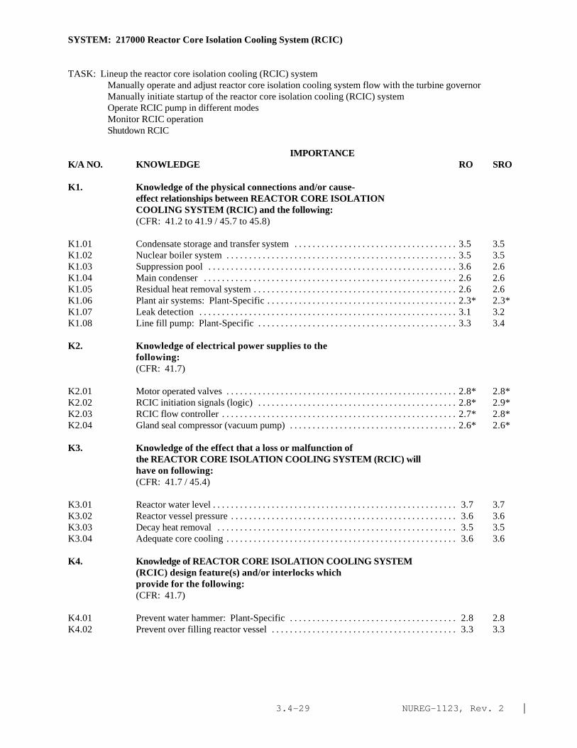
NUREG-1123, Rev. 2 |3.4-29
SYSTEM: 217000 Reactor Core Isolation Cooling System (RCIC)
TASK: Lineup the reactor core isolation cooling (RCIC) systemManually operate and adjust reactor core isolation cooling system flow with the turbine governorManually initiate startup of the reactor core isolation cooling (RCIC) systemOperate RCIC pump in different modesMonitor RCIC operationShutdown RCIC
IMPORTANCE K/A NO. KNOWLEDGE RO SRO
K1. Knowledge of the physical connections and/or cause-effect relationships between REACTOR CORE ISOLATIONCOOLING SYSTEM (RCIC) and the following:(CFR: 41.2 to 41.9 / 45.7 to 45.8)
K1.01 Condensate storage and transfer system . . . . . . . . . . . . . . . . . . . . . . . . . . . . . . . . . . . . 3.5 3.5K1.02 Nuclear boiler system . . . . . . . . . . . . . . . . . . . . . . . . . . . . . . . . . . . . . . . . . . . . . . . . . . . 3.5 3.5K1.03 Suppression pool . . . . . . . . . . . . . . . . . . . . . . . . . . . . . . . . . . . . . . . . . . . . . . . . . . . . . . . 3.6 2.6K1.04 Main condenser . . . . . . . . . . . . . . . . . . . . . . . . . . . . . . . . . . . . . . . . . . . . . . . . . . . . . . . . 2.6 2.6K1.05 Residual heat removal system . . . . . . . . . . . . . . . . . . . . . . . . . . . . . . . . . . . . . . . . . . . . . 2.6 2.6K1.06 Plant air systems: Plant-Specific . . . . . . . . . . . . . . . . . . . . . . . . . . . . . . . . . . . . . . . . . . 2.3* 2.3*K1.07 Leak detection . . . . . . . . . . . . . . . . . . . . . . . . . . . . . . . . . . . . . . . . . . . . . . . . . . . . . . . . . 3.1 3.2K1.08 Line fill pump: Plant-Specific . . . . . . . . . . . . . . . . . . . . . . . . . . . . . . . . . . . . . . . . . . . . 3.3 3.4
K2. Knowledge of electrical power supplies to thefollowing:(CFR: 41.7)
K2.01 Motor operated valves . . . . . . . . . . . . . . . . . . . . . . . . . . . . . . . . . . . . . . . . . . . . . . . . . . . 2.8* 2.8*K2.02 RCIC initiation signals (logic) . . . . . . . . . . . . . . . . . . . . . . . . . . . . . . . . . . . . . . . . . . . . 2.8* 2.9*K2.03 RCIC flow controller . . . . . . . . . . . . . . . . . . . . . . . . . . . . . . . . . . . . . . . . . . . . . . . . . . . . 2.7* 2.8*K2.04 Gland seal compressor (vacuum pump) . . . . . . . . . . . . . . . . . . . . . . . . . . . . . . . . . . . . . 2.6* 2.6*
K3. Knowledge of the effect that a loss or malfunction ofthe REACTOR CORE ISOLATION COOLING SYSTEM (RCIC) willhave on following:(CFR: 41.7 / 45.4)
K3.01 Reactor water level . . . . . . . . . . . . . . . . . . . . . . . . . . . . . . . . . . . . . . . . . . . . . . . . . . . . . . 3.7 3.7K3.02 Reactor vessel pressure . . . . . . . . . . . . . . . . . . . . . . . . . . . . . . . . . . . . . . . . . . . . . . . . . . 3.6 3.6K3.03 Decay heat removal . . . . . . . . . . . . . . . . . . . . . . . . . . . . . . . . . . . . . . . . . . . . . . . . . . . . . 3.5 3.5K3.04 Adequate core cooling . . . . . . . . . . . . . . . . . . . . . . . . . . . . . . . . . . . . . . . . . . . . . . . . . . . 3.6 3.6
K4. Knowledge of REACTOR CORE ISOLATION COOLING SYSTEM(RCIC) design feature(s) and/or interlocks whichprovide for the following:(CFR: 41.7)
K4.01 Prevent water hammer: Plant-Specific . . . . . . . . . . . . . . . . . . . . . . . . . . . . . . . . . . . . . 2.8 2.8K4.02 Prevent over filling reactor vessel . . . . . . . . . . . . . . . . . . . . . . . . . . . . . . . . . . . . . . . . . 3.3 3.3

NUREG-1123, Rev. 2 |3.4-30
SYSTEM: 217000 Reactor Core Isolation Cooling System (RCIC)
Tasks as noted previously
IMPORTANCE K/A NO. KNOWLEDGE RO SRO
K4.03 Prevents pump over heating . . . . . . . . . . . . . . . . . . . . . . . . . . . . . . . . . . . . . . . . . . . . . . . 2.9 3.0K4.04 Prevents turbine damage: Plant-Specific . . . . . . . . . . . . . . . . . . . . . . . . . . . . . . . . . . . 3.0 3.1K4.05 Prevents radioactivity release to auxiliary/reactor
building . . . . . . . . . . . . . . . . . . . . . . . . . . . . . . . . . . . . . . . . . . . . . . . . . . . . . . . . . . . . . . . 3.2 3.5K4.06 Manual initiation . . . . . . . . . . . . . . . . . . . . . . . . . . . . . . . . . . . . . . . . . . . . . . . . . . . . . . . . 3.5 3.5K4.07 Alternate supplies of water . . . . . . . . . . . . . . . . . . . . . . . . . . . . . . . . . . . . . . . . . . . . . . . 3.6 3.6
K5. Knowledge of the operational implications of thefollowing concepts as they apply to REACTOR COREISOLATION COOLING SYSTEM (RCIC) :(CFR: 41.5 / 45.3)
K5.01 Indications of pump cavitation . . . . . . . . . . . . . . . . . . . . . . . . . . . . . . . . . . . . . . . . . . . . 2.6* 2.6*K5.02 Flow indication . . . . . . . . . . . . . . . . . . . . . . . . . . . . . . . . . . . . . . . . . . . . . . . . . . . . . . . . . 3.1 3.1K5.03 Differential pressure indication . . . . . . . . . . . . . . . . . . . . . . . . . . . . . . . . . . . . . . . . . . . 2.6 2.6K5.04 Testable check valve operation . . . . . . . . . . . . . . . . . . . . . . . . . . . . . . . . . . . . . . . . . . . . 2.6 2.7K5.05 Centrifugal pump operation . . . . . . . . . . . . . . . . . . . . . . . . . . . . . . . . . . . . . . . . . . . . . . . 2.4* 2.4*K5.06 Turbine operation . . . . . . . . . . . . . . . . . . . . . . . . . . . . . . . . . . . . . . . . . . . . . . . . . . . . . . . 2.7* 2.7K5.07 Assist core cooling . . . . . . . . . . . . . . . . . . . . . . . . . . . . . . . . . . . . . . . . . . . . . . . . . . . . . 3.1 3.1
K6. Knowledge of the effect that a loss or malfunction ofthe following will have on the REACTOR CORE ISOLATIONCOOLING SYSTEM (RCIC) :(CFR: 41.7 / 45.7)
K6.01 Electrical power . . . . . . . . . . . . . . . . . . . . . . . . . . . . . . . . . . . . . . . . . . . . . . . . . . . . . . . . 3.4 3.5K6.02 Plant air systems . . . . . . . . . . . . . . . . . . . . . . . . . . . . . . . . . . . . . . . . . . . . . . . . . . . . . . . . 2.2* 2.2*|K6.03 Suppression pool water supply . . . . . . . . . . . . . . . . . . . . . . . . . . . . . . . . . . . . . . . . . . . . 3.5 3.5K6.04 Condensate storage and transfer system . . . . . . . . . . . . . . . . . . . . . . . . . . . . . . . . . . . . 3.5 3.5
ABILITY
Al. Ability to predict and/or monitor changes inparameters associated with operating the REACTOR COREISOLATION COOLING SYSTEM (RCIC) controls including:(CFR: 41.5 / 45.5)
A1.01 RCIC flow . . . . . . . . . . . . . . . . . . . . . . . . . . . . . . . . . . . . . . . . . . . . . . . . . . . . . . . . . . . . . 3.7 3.7A1.02 RCIC pressure . . . . . . . . . . . . . . . . . . . . . . . . . . . . . . . . . . . . . . . . . . . . . . . . . . . . . . . . . . 3.3 3.3A1.03 Reactor water level . . . . . . . . . . . . . . . . . . . . . . . . . . . . . . . . . . . . . . . . . . . . . . . . . . . . . 4.0 4.0A1.04 Reactor pressure . . . . . . . . . . . . . . . . . . . . . . . . . . . . . . . . . . . . . . . . . . . . . . . . . . . . . . . . 3.6* 3.6*|A1.05 RCIC turbine speed . . . . . . . . . . . . . . . . . . . . . . . . . . . . . . . . . . . . . . . . . . . . . . . . . . . . . 3.7 3.7A1.06 Condensate storage tank level . . . . . . . . . . . . . . . . . . . . . . . . . . . . . . . . . . . . . . . . . . . . . 3.2 3.3A1.07 Suppression pool level . . . . . . . . . . . . . . . . . . . . . . . . . . . . . . . . . . . . . . . . . . . . . . . . . . . 3.3 3.5A1.08 Suppression pool temperature . . . . . . . . . . . . . . . . . . . . . . . . . . . . . . . . . . . . . . . . . . . . . 3.5 3.6

NUREG-1123, Rev. 2 |3.4-31
SYSTEM: 217000 Reactor Core Isolation Cooling System (RCIC)
Tasks as noted previously
IMPORTANCE K/A NO. KNOWLEDGE RO SRO
A2. Ability to (a) predict the impacts of the following onthe REACTOR CORE ISOLATION COOLING SYSTEM (RCIC) ; and(b) based on those predictions, use procedures tocorrect, control, or mitigate the consequences ofthose abnormal conditions or operations:(CFR: 41.5 / 45.6)
A2.01 System initiation signal . . . . . . . . . . . . . . . . . . . . . . . . . . . . . . . . . . . . . . . . . . . . . . . . . . 3.8 3.7A2.02 Turbine trips . . . . . . . . . . . . . . . . . . . . . . . . . . . . . . . . . . . . . . . . . . . . . . . . . . . . . . . . . . . 3.8 3.7A2.03 Valve closures . . . . . . . . . . . . . . . . . . . . . . . . . . . . . . . . . . . . . . . . . . . . . . . . . . . . . . . . . . 3.4 3.3A2.04 A.C. power loss . . . . . . . . . . . . . . . . . . . . . . . . . . . . . . . . . . . . . . . . . . . . . . . . . . . . . . . . . 2.3* 2.3*A2.05 D.C. power loss . . . . . . . . . . . . . . . . . . . . . . . . . . . . . . . . . . . . . . . . . . . . . . . . . . . . . . . . 3.3 3.3A2.06 Loss of applicable plant air systems . . . . . . . . . . . . . . . . . . . . . . . . . . . . . . . . . . . . . . . . 2.2* 2.2* |A2.07 Loss of lube oil . . . . . . . . . . . . . . . . . . . . . . . . . . . . . . . . . . . . . . . . . . . . . . . . . . . . . . . . . 3.1 3.1A2.08 Loss of lube oil cooling . . . . . . . . . . . . . . . . . . . . . . . . . . . . . . . . . . . . . . . . . . . . . . . . . . 3.0 3.1A2.09 Loss of vacuum pump . . . . . . . . . . . . . . . . . . . . . . . . . . . . . . . . . . . . . . . . . . . . . . . . . . . . 2.9 3.0A2.10 Turbine control system failures . . . . . . . . . . . . . . . . . . . . . . . . . . . . . . . . . . . . . . . . . . . 3.1 3.1A2.11 Inadequate system flow . . . . . . . . . . . . . . . . . . . . . . . . . . . . . . . . . . . . . . . . . . . . . . . . . . 3.1 3.2A2.12 Valve openings . . . . . . . . . . . . . . . . . . . . . . . . . . . . . . . . . . . . . . . . . . . . . . . . . . . . . . . . . 3.0 3.0 |A2.13 Loss of room cooling . . . . . . . . . . . . . . . . . . . . . . . . . . . . . . . . . . . . . . . . . . . . . . . . . . . 2.9 3.0A2.14 Rupture disc failure: Exhaust-Diaphragm . . . . . . . . . . . . . . . . . . . . . . . . . . . . . . . . . . . 3.3 3.4A2.15 Steam line break . . . . . . . . . . . . . . . . . . . . . . . . . . . . . . . . . . . . . . . . . . . . . . . . . . . . . . . . 3.8 3.8A2.16 Low condensate storage tank level . . . . . . . . . . . . . . . . . . . . . . . . . . . . . . . . . . . . . . . . 3.5 3.4A2.17 High suppression pool level . . . . . . . . . . . . . . . . . . . . . . . . . . . . . . . . . . . . . . . . . . . . . . 3.2 3.4A2.18 Low suppression pool level . . . . . . . . . . . . . . . . . . . . . . . . . . . . . . . . . . . . . . . . . . . . . . 3.1 3.2A2.19 High suppression pool temperature . . . . . . . . . . . . . . . . . . . . . . . . . . . . . . . . . . . . . . . . 3.5 3.6
A3. Ability to monitor automatic operations of the REACTORCORE ISOLATION COOLING SYSTEM (RCIC) including:(CFR: 41.7 / 45.7)
A3.01 Valve operation . . . . . . . . . . . . . . . . . . . . . . . . . . . . . . . . . . . . . . . . . . . . . . . . . . . . . . . . . 3.5 3.5 |A3.02 Turbine startup . . . . . . . . . . . . . . . . . . . . . . . . . . . . . . . . . . . . . . . . . . . . . . . . . . . . . . . . . 3.6 3.5A3.03 System pressure . . . . . . . . . . . . . . . . . . . . . . . . . . . . . . . . . . . . . . . . . . . . . . . . . . . . . . . . 3.7 3.6A3.04 System flow . . . . . . . . . . . . . . . . . . . . . . . . . . . . . . . . . . . . . . . . . . . . . . . . . . . . . . . . . . . 3.6 3.5A3.05 Reactor water level . . . . . . . . . . . . . . . . . . . . . . . . . . . . . . . . . . . . . . . . . . . . . . . . . . . . . 3.9 3.9A3.06 Lights and alarms . . . . . . . . . . . . . . . . . . . . . . . . . . . . . . . . . . . . . . . . . . . . . . . . . . . . . . . 3.5 3.4
A4. Ability to manually operate and/or monitor in thecontrol room:(CFR: 41.7 / 45.5 to 45.8)
A4.01 RCIC turbine speed . . . . . . . . . . . . . . . . . . . . . . . . . . . . . . . . . . . . . . . . . . . . . . . . . . . . . 3.7 3.7A4.02 Turbine trip throttle valve reset . . . . . . . . . . . . . . . . . . . . . . . . . . . . . . . . . . . . . . . . . . . . 3.9 3.9A4.03 System valves . . . . . . . . . . . . . . . . . . . . . . . . . . . . . . . . . . . . . . . . . . . . . . . . . . . . . . . . . . 3.4 3.3A4.04 Manually initiated controls . . . . . . . . . . . . . . . . . . . . . . . . . . . . . . . . . . . . . . . . . . . . . . . 3.6 3.6

NUREG-1123, Rev. 2 |3.4-32
SYSTEM: 217000 Reactor Core Isolation Cooling System (RCIC)
Tasks as noted previously
IMPORTANCE K/A NO. KNOWLEDGE RO SRO
A4.05 Reactor water level . . . . . . . . . . . . . . . . . . . . . . . . . . . . . . . . . . . . . . . . . . . . . . . . . . . . . . 4.1 4.1A4.06 Suppression pool level . . . . . . . . . . . . . . . . . . . . . . . . . . . . . . . . . . . . . . . . . . . . . . . . . . . 3.6 3.7A4.07 Reactor pressure . . . . . . . . . . . . . . . . . . . . . . . . . . . . . . . . . . . . . . . . . . . . . . . . . . . . . . . . 3.9 3.8A4.08 System flow . . . . . . . . . . . . . . . . . . . . . . . . . . . . . . . . . . . . . . . . . . . . . . . . . . . . . . . . . . . 3.7 3.6A4.09 System pressure . . . . . . . . . . . . . . . . . . . . . . . . . . . . . . . . . . . . . . . . . . . . . . . . . . . . . . . . 3.7 3.6A4.10 Lights and alarms . . . . . . . . . . . . . . . . . . . . . . . . . . . . . . . . . . . . . . . . . . . . . . . . . . . . . . . 3.6 3.5A4.11 Condensate storage tank level . . . . . . . . . . . . . . . . . . . . . . . . . . . . . . . . . . . . . . . . . . . . . 3.5 3.5

NUREG-1123, Rev. 2 |3.4-33
SYSTEM: 202001 Recirculation System
TASK: Perform lineups on the recirculation system Vent recirculation pump seals Startup a recirculation pump (startup a second recirculation pump)Operate recirculation pumps in various control modes (adjust the recirculation flow using "master manual"control) Monitor recirculation pumps in operation Monitor jet pump operation Secure a recirculation pump Perform jet pump operability test Conduct heatup and cooldown temperature checks Conduct recirculation pump startup check of the delta temperature between the reactor coolant in the idleloop to the reactor vesselConduct recirculation pump trip logic system functional test Conduct recirculation loop valve operability test Conduct recirculation system valve testing What if jet pumps not operating within required operating band
IMPORTANCE K/A NO. KNOWLEDGE RO SRO
K1. Knowledge of the physical connections and/or cause-effect relationships between RECIRCULATION SYSTEM andthe following:(CFR: 41.2 to 41.9 / 45.7 to 45.8)
K1.01 Core flow . . . . . . . . . . . . . . . . . . . . . . . . . . . . . . . . . . . . . . . . . . . . . . . . . . . . . . . . . . . . . . 3.6 3.7K1.02 Reactor power . . . . . . . . . . . . . . . . . . . . . . . . . . . . . . . . . . . . . . . . . . . . . . . . . . . . . . . . . . 4.1 4.1K1.03 Reactor moderator temperature . . . . . . . . . . . . . . . . . . . . . . . . . . . . . . . . . . . . . . . . . . . . 3.2 3.3K1.04 Reactor/turbine pressure regulating system: Plant-
Specific . . . . . . . . . . . . . . . . . . . . . . . . . . . . . . . . . . . . . . . . . . . . . . . . . . . . . . . . . . . . . . . 3.3 3.3K1.05 Reactor pressure . . . . . . . . . . . . . . . . . . . . . . . . . . . . . . . . . . . . . . . . . . . . . . . . . . . . . . . . 3.4 3.4K1.06 Jet pumps . . . . . . . . . . . . . . . . . . . . . . . . . . . . . . . . . . . . . . . . . . . . . . . . . . . . . . . . . . . . . . 3.6 3.6K1.07 Component cooling water systems . . . . . . . . . . . . . . . . . . . . . . . . . . . . . . . . . . . . . . . . . 3.1 3.2K1.08 A.C. electrical . . . . . . . . . . . . . . . . . . . . . . . . . . . . . . . . . . . . . . . . . . . . . . . . . . . . . . . . . . 3.1 3.2K1.09 D.C. electrical . . . . . . . . . . . . . . . . . . . . . . . . . . . . . . . . . . . . . . . . . . . . . . . . . . . . . . . . . . 2.7 2.9K1.10 Control rod drive system: Plant-Specific . . . . . . . . . . . . . . . . . . . . . . . . . . . . . . . . . . . 2.8 2.8K1.11 Drywell equipment drain sump . . . . . . . . . . . . . . . . . . . . . . . . . . . . . . . . . . . . . . . . . . . . . 2.7 2.8K1.12 Recirculation system motor-generator sets: Plant-
Specific . . . . . . . . . . . . . . . . . . . . . . . . . . . . . . . . . . . . . . . . . . . . . . . . . . . . . . . . . . . . . . . 3.6 3.6K1.13 Jet pump ring header and risers: Plant-Specific . . . . . . . . . . . . . . . . . . . . . . . . . . . . . . 3.1 3.2K1.14 Rod block monitor: Plant-Specific . . . . . . . . . . . . . . . . . . . . . . . . . . . . . . . . . . . . . . . . . 3.0 3.2K1.15 Nuclear boiler instrumentation (reactor water
level/pressure) . . . . . . . . . . . . . . . . . . . . . . . . . . . . . . . . . . . . . . . . . . . . . . . . . . . . . . . . . . 3.2 3.2K1.16 Low pressure coolant injection logic: Plant-Specific . . . . . . . . . . . . . . . . . . . . . . . . . . 3.9 3.9K1.17 Vessel bottom head drain temperature . . . . . . . . . . . . . . . . . . . . . . . . . . . . . . . . . . . . . . 3.1 3.3K1.18 RHR shutdown cooling mode . . . . . . . . . . . . . . . . . . . . . . . . . . . . . . . . . . . . . . . . . . . . . . 3.3 3.3K1.19 Feedwater flow . . . . . . . . . . . . . . . . . . . . . . . . . . . . . . . . . . . . . . . . . . . . . . . . . . . . . . . . . 3.2 3.2K1.20 Plant air systems: Plant-Specific . . . . . . . . . . . . . . . . . . . . . . . . . . . . . . . . . . . . . . . . . . 2.4 2.5K1.21 Reactor water cleanup system . . . . . . . . . . . . . . . . . . . . . . . . . . . . . . . . . . . . . . . . . . . . . 2.6 2.6

NUREG-1123, Rev. 2 |3.4-34
SYSTEM: 202001 Recirculation System
Tasks as noted previously
IMPORTANCE K/A NO. KNOWLEDGE RO SRO
K1.22 Reactor water level . . . . . . . . . . . . . . . . . . . . . . . . . . . . . . . . . . . . . . . . . . . . . . . . . . . . . 3.5 3.6K1.23 Average power range monitor flow converters: Plant-
Specific . . . . . . . . . . . . . . . . . . . . . . . . . . . . . . . . . . . . . . . . . . . . . . . . . . . . . . . . . . . . . . 3.4 3.5K1.24 Isolation condenser: Plant-Specific . . . . . . . . . . . . . . . . . . . . . . . . . . . . . . . . . . . . . . . 3.4 3.4K1.25 Reactor water sampling system . . . . . . . . . . . . . . . . . . . . . . . . . . . . . . . . . . . . . . . . . . . . 2.6 2.7K1.26 Recirculation flow control system: Plant-SpecificK1.27 ATWS circuitry: Plant-Specific . . . . . . . . . . . . . . . . . . . . . . . . . . . . . . . . . . . . . . . . . . 4.1 4.3*|K1.28 End-of-cycle recirculation pump trip circuitry:
Plant-Specific . . . . . . . . . . . . . . . . . . . . . . . . . . . . . . . . . . . . . . . . . . . . . . . . . . . . . . . . . 3.9 4.1
K2. Knowledge of electrical power supplies to thefollowing:(CFR: 41.7)
K2.01 Recirculation pumps: Plant-Specific . . . . . . . . . . . . . . . . . . . . . . . . . . . . . . . . . . . . . . 3.2* 3.2K2.02 MG sets: Plant-Specific . . . . . . . . . . . . . . . . . . . . . . . . . . . . . . . . . . . . . . . . . . . . . . . . 3.2 3.3K2.03 Recirculation system valves . . . . . . . . . . . . . . . . . . . . . . . . . . . . . . . . . . . . . . . . . . . . . . 2.7* 2.8*K2.04 Hydraulic power unit oil pumps: Plant-Specific . . . . . . . . . . . . . . . . . . . . . . . . . . . . . 2.5* 2.5*K2.05 MG set oil pumps: Plant-Specific . . . . . . . . . . . . . . . . . . . . . . . . . . . . . . . . . . . . . . . . 2.3* 2.3*
K3. Knowledge of the effect that a loss or malfunction ofthe RECIRCULATION SYSTEM will have on following:(CFR: 41.7 / 45.4)
K3.01 Core flow . . . . . . . . . . . . . . . . . . . . . . . . . . . . . . . . . . . . . . . . . . . . . . . . . . . . . . . . . . . . . 3.6 3.6K3.02 Load following capabilities: Plant-Specific . . . . . . . . . . . . . . . . . . . . . . . . . . . . . . . . 2.8 2.8K3.03 Reactor power . . . . . . . . . . . . . . . . . . . . . . . . . . . . . . . . . . . . . . . . . . . . . . . . . . . . . . . . . 3.9 3.9K3.04 Reactor water level . . . . . . . . . . . . . . . . . . . . . . . . . . . . . . . . . . . . . . . . . . . . . . . . . . . . . 3.7 3.7K3.05 Recirculation system MG sets: Plant-Specific . . . . . . . . . . . . . . . . . . . . . . . . . . . . . . 3.3 3.3K3.06 Low pressure coolant injection logic: Plant-Specific . . . . . . . . . . . . . . . . . . . . . . . . . 3.7 3.9K3.07 Vessel bottom head drain temperature . . . . . . . . . . . . . . . . . . . . . . . . . . . . . . . . . . . . . . 2.9 2.9K3.08 Shutdown cooling system . . . . . . . . . . . . . . . . . . . . . . . . . . . . . . . . . . . . . . . . . . . . . . . . 2.8 2.9K3.09 Reactor water cleanup system . . . . . . . . . . . . . . . . . . . . . . . . . . . . . . . . . . . . . . . . . . . . 2.4* 2.5*K3.10 Average power range monitor flow converters . . . . . . . . . . . . . . . . . . . . . . . . . . . . . . . 3.3 3.4K3.11 Component cooling water systems . . . . . . . . . . . . . . . . . . . . . . . . . . . . . . . . . . . . . . . . 2.3* 2.3*K3.12 Isolation condenser: Plant-Specific . . . . . . . . . . . . . . . . . . . . . . . . . . . . . . . . . . . . . . . 3.0 3.0K3.13 Reactor water sampling system . . . . . . . . . . . . . . . . . . . . . . . . . . . . . . . . . . . . . . . . . . . 2.5 2.5K3.14 Primary containment integrity: Plant-Specific . . . . . . . . . . . . . . . . . . . . . . . . . . . . . . 3.5 3.5
K4. Knowledge of RECIRCULATION System design feature(s)and/or interlocks which provide for the following:(CFR: 41.7)
K4.01 2/3 core coverage: Plant-Specific . . . . . . . . . . . . . . . . . . . . . . . . . . . . . . . . . . . . . . . . 3.9 3.9K4.02 Adequate recirculation pump NPSH . . . . . . . . . . . . . . . . . . . . . . . . . . . . . . . . . . . . . . . 3.1 3.2K4.03 Recirculation pump motor cooling . . . . . . . . . . . . . . . . . . . . . . . . . . . . . . . . . . . . . . . . 2.8 2.8K4.04 Controlled seal flow . . . . . . . . . . . . . . . . . . . . . . . . . . . . . . . . . . . . . . . . . . . . . . . . . . . . 3.0 3.1K4.05 Seal cooling . . . . . . . . . . . . . . . . . . . . . . . . . . . . . . . . . . . . . . . . . . . . . . . . . . . . . . . . . . . 2.9 2.9

NUREG-1123, Rev. 2 |3.4-35
SYSTEM: 202001 Recirculation System
Tasks as noted previously
IMPORTANCE K/A NO. KNOWLEDGE RO SRO
K4.06 Automatic voltage/frequency regulation: Plant-Specific . . . . . . . . . . . . . . . . . . . . . . . . . . . . . . . . . . . . . . . . . . . . . . . . . . . . . . . . . . . . . . 2.6* 2.7
K4.07 Motor generator set trips: Plant-Specific . . . . . . . . . . . . . . . . . . . . . . . . . . . . . . . . . . 2.8 2.9K4.08 Oil pump automatic starts: Plant-Specific . . . . . . . . . . . . . . . . . . . . . . . . . . . . . . . . . . 2.8 2.9K4.09 Pump minimum flow limit: Plant-Specific . . . . . . . . . . . . . . . . . . . . . . . . . . . . . . . . . 2.7 2.9K4.10 Pump start permissives: Plant-Specific . . . . . . . . . . . . . . . . . . . . . . . . . . . . . . . . . . . . 3.3 3.4K4.11 Limitation of recirculation pumps flow mismatch:
Plant-Specific . . . . . . . . . . . . . . . . . . . . . . . . . . . . . . . . . . . . . . . . . . . . . . . . . . . . . . . . . 3.1 3.5K4.12 Minimization of reactor vessel bottom head temperature
gradients: Plant-Specific . . . . . . . . . . . . . . . . . . . . . . . . . . . . . . . . . . . . . . . . . . . . . . . . 3.2 3.5K4.13 †End of cycle recirculation pump trip: Plant-Specific . . . . . . . . . . . . . . . . . . . . . . . . 3.7 4.0*K4.14 ATWS: Plant-Specific . . . . . . . . . . . . . . . . . . . . . . . . . . . . . . . . . . . . . . . . . . . . . . . . . . 4.0 4.1*K4.15 Slow speed pump start: Plant-Specific . . . . . . . . . . . . . . . . . . . . . . . . . . . . . . . . . . . . . 3.1 3.4K4.16 Recirculation pump downshift/runback: Plant-Specific . . . . . . . . . . . . . . . . . . . . . . . 3.3 3.6K4.17 Fast speed pump start: Plant-Specific . . . . . . . . . . . . . . . . . . . . . . . . . . . . . . . . . . . . . 3.3 3.5K4.18 Automatic MG set start sequencing: Plant-Specific . . . . . . . . . . . . . . . . . . . . . . . . . . 2.8 3.0
K5. Knowledge of the operational implications of thefollowing concepts as they apply to RECIRCULATIONSYSTEM :(CFR: 41.5 / 45.3)
K5.01 Indications of pump cavitation . . . . . . . . . . . . . . . . . . . . . . . . . . . . . . . . . . . . . . . . . . . . 2.7 2.8K5.02 Jet pump operation: BWR-3,4,5,6 . . . . . . . . . . . . . . . . . . . . . . . . . . . . . . . . . . . . . . . . 3.1 3.2K5.03 Pump/motor cooling: Plant-Specific . . . . . . . . . . . . . . . . . . . . . . . . . . . . . . . . . . . . . . 2.7 2.7K5.04 System venting . . . . . . . . . . . . . . . . . . . . . . . . . . . . . . . . . . . . . . . . . . . . . . . . . . . . . . . . . 2.4 2.6K5.05 End of cycle recirculation pump trip: Plant-Specific . . . . . . . . . . . . . . . . . . . . . . . . . 3.5 3.6K5.06 ATWS RPT: Plant-Specific . . . . . . . . . . . . . . . . . . . . . . . . . . . . . . . . . . . . . . . . . . . . . . 3.6 3.7K5.07 Natural circulation: Plant-Specific . . . . . . . . . . . . . . . . . . . . . . . . . . . . . . . . . . . . . . . . 3.3 3.4K5.08 E/P converters: Plant-Specific . . . . . . . . . . . . . . . . . . . . . . . . . . . . . . . . . . . . . . . . . . . 2.0* 2.1*K5.09 Hydraulically operated valves: Plant-Specific . . . . . . . . . . . . . . . . . . . . . . . . . . . . . . . 2.6* 2.6*K5.10 Motor generator set operation: Plant-Specific . . . . . . . . . . . . . . . . . . . . . . . . . . . . . . 2.8* 2.8
K6. Knowledge of the effect that a loss or malfunction ofthe following will have on the RECIRCULATION SYSTEM :(CFR: 41.7 / 45.7)
K6.01 Jet pumps: Plant-Specific . . . . . . . . . . . . . . . . . . . . . . . . . . . . . . . . . . . . . . . . . . . . . . . 3.5 3.7K6.02 Component cooling water systems . . . . . . . . . . . . . . . . . . . . . . . . . . . . . . . . . . . . . . . . 3.1 3.2K6.03 A.C. power: Plant-Specific . . . . . . . . . . . . . . . . . . . . . . . . . . . . . . . . . . . . . . . . . . . . . . 2.9 3.0K6.04 D.C. power: Plant-Specific . . . . . . . . . . . . . . . . . . . . . . . . . . . . . . . . . . . . . . . . . . . . . . 2.7 2.8K6.05 Control rod drive system: Plant-Specific . . . . . . . . . . . . . . . . . . . . . . . . . . . . . . . . . . 2.7 2.7K6.06 Recirculation system motor-generator sets: Plant-
Specific . . . . . . . . . . . . . . . . . . . . . . . . . . . . . . . . . . . . . . . . . . . . . . . . . . . . . . . . . . . . . . 3.1 3.1K6.07 Feedwater flow . . . . . . . . . . . . . . . . . . . . . . . . . . . . . . . . . . . . . . . . . . . . . . . . . . . . . . . . 3.3 3.3K6.08 Reactor water cleanup system . . . . . . . . . . . . . . . . . . . . . . . . . . . . . . . . . . . . . . . . . . . . 2.3 2.3K6.09 Reactor water level . . . . . . . . . . . . . . . . . . . . . . . . . . . . . . . . . . . . . . . . . . . . . . . . . . . . . 3.4 3.4

NUREG-1123, Rev. 2 |3.4-36
SYSTEM: 202001 Recirculation System Tasks as noted previously
Tasks as noted previously
IMPORTANCE K/A NO. KNOWLEDGE RO SRO
A1. Ability to predict and/or monitor changes inparameters associated with operating the RECIRCULATIONSYSTEM controls including:(CFR: 41.5 / 45.5)
A1.01 Recirculation pump flow: Plant-Specific . . . . . . . . . . . . . . . . . . . . . . . . . . . . . . . . . . . 3.6 3.5A1.02 Jet pump flow . . . . . . . . . . . . . . . . . . . . . . . . . . . . . . . . . . . . . . . . . . . . . . . . . . . . . . . . . . 3.4 3.4A1.03 Core flow . . . . . . . . . . . . . . . . . . . . . . . . . . . . . . . . . . . . . . . . . . . . . . . . . . . . . . . . . . . . . 3.6 3.6A1.04 Reactor water level . . . . . . . . . . . . . . . . . . . . . . . . . . . . . . . . . . . . . . . . . . . . . . . . . . . . . 3.3 3.3A1.05 Reactor power . . . . . . . . . . . . . . . . . . . . . . . . . . . . . . . . . . . . . . . . . . . . . . . . . . . . . . . . . 3.9 3.9A1.06 Recirculation pump motor amps . . . . . . . . . . . . . . . . . . . . . . . . . . . . . . . . . . . . . . . . . . 2.5 2.6A1.07 Recirculation pump speed . . . . . . . . . . . . . . . . . . . . . . . . . . . . . . . . . . . . . . . . . . . . . . . 2.7 2.8A1.08 Recirculation FCV position: BWR-5,6 . . . . . . . . . . . . . . . . . . . . . . . . . . . . . . . . . . . . 3.7 3.7A1.09 Recirculation pump seal pressures . . . . . . . . . . . . . . . . . . . . . . . . . . . . . . . . . . . . . . . . 3.3 3.3A1.10 Recirculation seal purge flows . . . . . . . . . . . . . . . . . . . . . . . . . . . . . . . . . . . . . . . . . . . . 2.6 2.7A1.11 Vessel bottom head drain temperature . . . . . . . . . . . . . . . . . . . . . . . . . . . . . . . . . . . . . 2.8 2.9A1.12 Recirculation pump differential pressure: Plant-
Specific . . . . . . . . . . . . . . . . . . . . . . . . . . . . . . . . . . . . . . . . . . . . . . . . . . . . . . . . . . . . . . 2.6 2.6A1.13 Recirculation loop temperatures: Plant-Specific . . . . . . . . . . . . . . . . . . . . . . . . . . . . 3.1 3.2A1.14 Recirculation drive motor temperature: Plant-Specific
. . . . . . . . . . . . . . . . . . . . . . . . . . . . . . . . . . . . . . . . . . . . . . . . . . . . . . . . . . . . . . . . . . . . . . 2.4 2.4A1.15 Recirculation MG set temperatures: Plant-Specific . . . . . . . . . . . . . . . . . . . . . . . . . . 2.4 2.4A1.16 Recirculation MG drive motor amps: Plant-Specific . . . . . . . . . . . . . . . . . . . . . . . . . 2.3* 2.3A1.17 Recirculation MG set generator current, power,
voltage: Plant-Specific . . . . . . . . . . . . . . . . . . . . . . . . . . . . . . . . . . . . . . . . . . . . . . . . . . 2.3* 2.3
A2. Ability to (a) predict the impacts of the following onthe RECIRCULATION SYSTEM ; and (b) based on thosepredictions, use procedures to correct, control, ormitigate the consequences of those abnormal conditionsor operations:(CFR: 41.5 / 45.6)
A2.01 †Jet pump failure: Plant-Specific . . . . . . . . . . . . . . . . . . . . . . . . . . . . . . . . . . . . . . . . . 3.4 3.9A2.02 Recirculation system leak . . . . . . . . . . . . . . . . . . . . . . . . . . . . . . . . . . . . . . . . . . . . . . . 3.7 3.9A2.03 Single recirculation pump trip . . . . . . . . . . . . . . . . . . . . . . . . . . . . . . . . . . . . . . . . . . . . 3.6 3.7A2.04 Multiple recirculation pump trip . . . . . . . . . . . . . . . . . . . . . . . . . . . . . . . . . . . . . . . . . . 3.7 3.8A2.05 Inadvertent recirculation flow increase . . . . . . . . . . . . . . . . . . . . . . . . . . . . . . . . . . . . . 3.8 4.0A2.06 Inadvertent recirculation flow decrease . . . . . . . . . . . . . . . . . . . . . . . . . . . . . . . . . . . . 3.6 3.8A2.07 Recirculation pump speed mismatch: Plant-Specific . . . . . . . . . . . . . . . . . . . . . . . . . 3.1 3.3A2.08 Recirculation flow mismatch: Plant-Specific . . . . . . . . . . . . . . . . . . . . . . . . . . . . . . . 3.1 3.4A2.09 Recirculation scoop tube lockup: Plant-Specific . . . . . . . . . . . . . . . . . . . . . . . . . . . . 3.2 3.4A2.10 †Recirculation pump seal failure . . . . . . . . . . . . . . . . . . . . . . . . . . . . . . . . . . . . . . . . . . 3.5 3.9A2.11 Low reactor water level . . . . . . . . . . . . . . . . . . . . . . . . . . . . . . . . . . . . . . . . . . . . . . . . . 3.7 3.9A2.12 Loss of reactor feedwater . . . . . . . . . . . . . . . . . . . . . . . . . . . . . . . . . . . . . . . . . . . . . . . . 3.6 3.8A2.13 Carryunder . . . . . . . . . . . . . . . . . . . . . . . . . . . . . . . . . . . . . . . . . . . . . . . . . . . . . . . . . . . . 2.6 2.8

NUREG-1123, Rev. 2 |3.4-37
SYSTEM: 202001 Recirculation System
Tasks as noted previously
IMPORTANCE K/A NO. KNOWLEDGE RO SRO
A2.14 High reactor pressure (ATWS circuitry initiation):Plant-Specific . . . . . . . . . . . . . . . . . . . . . . . . . . . . . . . . . . . . . . . . . . . . . . . . . . . . . . . . . . 3.9 4.2* |
A2.15 End of cycle trip circuitry: Plant-Specific . . . . . . . . . . . . . . . . . . . . . . . . . . . . . . . . . . . 3.7 3.9A2.16 Loss of seal purge flow (CRD) . . . . . . . . . . . . . . . . . . . . . . . . . . . . . . . . . . . . . . . . . . . . 2.9 3.1A2.17 Loss of seal cooling water . . . . . . . . . . . . . . . . . . . . . . . . . . . . . . . . . . . . . . . . . . . . . . . . 3.1 3.2A2.18 Loss of motor cooling . . . . . . . . . . . . . . . . . . . . . . . . . . . . . . . . . . . . . . . . . . . . . . . . . . . 2.9 3.1A2.19 Loss of A.C. power: Plant-Specific . . . . . . . . . . . . . . . . . . . . . . . . . . . . . . . . . . . . . . . . . 3.1 3.2A2.20 Loss of D.C. power: Plant-Specific . . . . . . . . . . . . . . . . . . . . . . . . . . . . . . . . . . . . . . . . 2.8 2.9A2.21 †Recirculation loop temperature out of spec: Plant-
Specific . . . . . . . . . . . . . . . . . . . . . . . . . . . . . . . . . . . . . . . . . . . . . . . . . . . . . . . . . . . . . . . 3.3 3 7A2.22 Loss of component cooling water . . . . . . . . . . . . . . . . . . . . . . . . . . . . . . . . . . . . . . . . . . 3.1 3.2A2.23 Valve closures . . . . . . . . . . . . . . . . . . . . . . . . . . . . . . . . . . . . . . . . . . . . . . . . . . . . . . . . . . 3.2 3.2A2.24 Valve opening . . . . . . . . . . . . . . . . . . . . . . . . . . . . . . . . . . . . . . . . . . . . . . . . . . . . . . . . . . . 3.1 3.1A2.25 Recirculation flow control valve lockup: Plant-
Specific . . . . . . . . . . . . . . . . . . . . . . . . . . . . . . . . . . . . . . . . . . . . . . . . . . . . . . . . . . . . . . . 3.3 3.3A2.26 Incomplete start sequence: Plant-Specific . . . . . . . . . . . . . . . . . . . . . . . . . . . . . . . . . . 2.9 3.1
A3. Ability to monitor automatic operations of theRECIRCULATION SYSTEM including:(CFR: 41.7 / 45.7)
A3.01 Valve operation . . . . . . . . . . . . . . . . . . . . . . . . . . . . . . . . . . . . . . . . . . . . . . . . . . . . . . . . . 3.1 3.1A3.02 Pump/MG set start sequence: Plant-Specific . . . . . . . . . . . . . . . . . . . . . . . . . . . . . . . . 3.1 3.0A3.03 System flow . . . . . . . . . . . . . . . . . . . . . . . . . . . . . . . . . . . . . . . . . . . . . . . . . . . . . . . . . . . . 3.2 3.2A3.04 Lights and alarms . . . . . . . . . . . . . . . . . . . . . . . . . . . . . . . . . . . . . . . . . . . . . . . . . . . . . . . . 3.2 3.1A3.05 Pump speed: Plant-Specific . . . . . . . . . . . . . . . . . . . . . . . . . . . . . . . . . . . . . . . . . . . . . . 2.9 2.9A3.06 Flow control valve position: BWR-5,6 . . . . . . . . . . . . . . . . . . . . . . . . . . . . . . . . . . . . . 3.6 3.6A3.07 Pump trips: Plant-Specific . . . . . . . . . . . . . . . . . . . . . . . . . . . . . . . . . . . . . . . . . . . . . . . 3.3 3.3A3.08 Pump downshift: BWR-5,6 . . . . . . . . . . . . . . . . . . . . . . . . . . . . . . . . . . . . . . . . . . . . . . . 3.4 3.3A3.09 MG set trip: Plant-Specific . . . . . . . . . . . . . . . . . . . . . . . . . . . . . . . . . . . . . . . . . . . . . . . 3.3 3.3
A4. Ability to manually operate and/or monitor in thecontrol room:(CFR: 41.7 / 45.5 to 45.8)
A4.01 Recirculation pumps . . . . . . . . . . . . . . . . . . . . . . . . . . . . . . . . . . . . . . . . . . . . . . . . . . . . . 3.7 3.7A4.02 System valves . . . . . . . . . . . . . . . . . . . . . . . . . . . . . . . . . . . . . . . . . . . . . . . . . . . . . . . . . . . 3.5 3.4A4.03 Reactor power . . . . . . . . . . . . . . . . . . . . . . . . . . . . . . . . . . . . . . . . . . . . . . . . . . . . . . . . . . 4.1 4.1A4.04 System flow . . . . . . . . . . . . . . . . . . . . . . . . . . . . . . . . . . . . . . . . . . . . . . . . . . . . . . . . . . . . 3.7 3.7A4.05 Lights and alarms . . . . . . . . . . . . . . . . . . . . . . . . . . . . . . . . . . . . . . . . . . . . . . . . . . . . . . . . 3.3 3.3A4.06 Oil pumps . . . . . . . . . . . . . . . . . . . . . . . . . . . . . . . . . . . . . . . . . . . . . . . . . . . . . . . . . . . . . . 2.7 2.7A4.07 Vent fans: Plant-Specific . . . . . . . . . . . . . . . . . . . . . . . . . . . . . . . . . . . . . . . . . . . . . . . . . 2.4 2.3A4.08 Motor-generator sets: Plant-Specific . . . . . . . . . . . . . . . . . . . . . . . . . . . . . . . . . . . . . . 3.2 3.1A4.09 Reactor water level . . . . . . . . . . . . . . . . . . . . . . . . . . . . . . . . . . . . . . . . . . . . . . . . . . . . . . 3.7 3.7A4.10 Seal flow: Plant-Specific . . . . . . . . . . . . . . . . . . . . . . . . . . . . . . . . . . . . . . . . . . . . . . . . . 2.8 2.8A4.11 Seal pressures: Plant-Specific . . . . . . . . . . . . . . . . . . . . . . . . . . . . . . . . . . . . . . . . . . . . 3.2 3.3A4.12 Core flow . . . . . . . . . . . . . . . . . . . . . . . . . . . . . . . . . . . . . . . . . . . . . . . . . . . . . . . . . . . . . . 3.9 3.8A4.13 Core differential pressure . . . . . . . . . . . . . . . . . . . . . . . . . . . . . . . . . . . . . . . . . . . . . . . . 3.1 3.3

NUREG-1123, Rev. 2 |3.4-38
SYSTEM: 203000 RHR/LPCI: Injection Mode (Plant Specific)
TASK: Perform lineups on the low pressure coolant injection systemPlace the low pressure coolant injection system in standby readinessMonitor operational sequence of low pressure coolant injection (LPCI) systemSecure the low pressure coolant injection systemPerform LPCI subsystem logic system functional testPerform LPCI mode inoperable testPerform LPCI mov power supply simulated auto. act test and battery serv. testsConduct LPCI independent power supply weekly battery testConduct LPCI independent power supply performance discharge testPerform low pressure coolant injection sound analysis and flow test (write in)
IMPORTANCE K/A NO. KNOWLEDGE RO SRO
K1. Knowledge of the physical connections and/or cause-effect relationships between RHR/LPCI: INJECTION MODE(PLANT SPECIFIC) and the following:(CFR: 41.2 to 41.9 / 45.7 to 45.8)
K1.01 Condensate storage and transfer system: Plant-Specific . . . . . . . . . . . . . . . . . . . . . . . . . . . . . . . . . . . . . . . . . . . . . . . . . . . . . . . . . . . . . . . 2.8 2.8
K1.02 Suppression pool . . . . . . . . . . . . . . . . . . . . . . . . . . . . . . . . . . . . . . . . . . . . . . . . . . . . . . . 3.9 3.9K1.03 Condensate transfer . . . . . . . . . . . . . . . . . . . . . . . . . . . . . . . . . . . . . . . . . . . . . . . . . . . . . 2.5* 2.6*K1.04 Keep fill system . . . . . . . . . . . . . . . . . . . . . . . . . . . . . . . . . . . . . . . . . . . . . . . . . . . . . . . . 3.3 3.4K1.05 Recirculation system: BWR-3,4 . . . . . . . . . . . . . . . . . . . . . . . . . . . . . . . . . . . . . . . . . . 3.8 3.8K1.06 Automatic depressurization . . . . . . . . . . . . . . . . . . . . . . . . . . . . . . . . . . . . . . . . . . . . . . . 3.9 3.9K1.07 D.C. electrical power . . . . . . . . . . . . . . . . . . . . . . . . . . . . . . . . . . . . . . . . . . . . . . . . . . . . 3.1 3.3K1.08 A.C. electrical power . . . . . . . . . . . . . . . . . . . . . . . . . . . . . . . . . . . . . . . . . . . . . . . . . . . . 3.5 3.5K1.09 Emergency generators . . . . . . . . . . . . . . . . . . . . . . . . . . . . . . . . . . . . . . . . . . . . . . . . . . . 3.8 3.8K1.10 ECCS room coolers . . . . . . . . . . . . . . . . . . . . . . . . . . . . . . . . . . . . . . . . . . . . . . . . . . . . . 3.2 3.2K1.11 Nuclear boiler instrumentation . . . . . . . . . . . . . . . . . . . . . . . . . . . . . . . . . . . . . . . . . . . . 3.7 3.7K1.12 Plant air systems: Plant-Specific . . . . . . . . . . . . . . . . . . . . . . . . . . . . . . . . . . . . . . . . . . 2.6* 2.7*K1.13 Drywell pressure . . . . . . . . . . . . . . . . . . . . . . . . . . . . . . . . . . . . . . . . . . . . . . . . . . . . . . . 3.9 4.0K1.14 Shutdown cooling system: Plant-Specific . . . . . . . . . . . . . . . . . . . . . . . . . . . . . . . . . . 3.6 3.7K1.15 Reactor building drain system: Plant-Specific . . . . . . . . . . . . . . . . . . . . . . . . . . . . . . . 2.4* 2.6K1.16 Component cooling water systems . . . . . . . . . . . . . . . . . . . . . . . . . . . . . . . . . . . . . . . . . 3.1 3.2K1.17 Reactor pressure . . . . . . . . . . . . . . . . . . . . . . . . . . . . . . . . . . . . . . . . . . . . . . . . . . . . . . . . 4.0 4.0K1.18 Reactor vessel: Plant-Specific . . . . . . . . . . . . . . . . . . . . . . . . . . . . . . . . . . . . . . . . . . . . 3.8 3.8
K2. Knowledge of electrical power supplies to thefollowing:(CFR: 41.7)
K2.01 Pumps . . . . . . . . . . . . . . . . . . . . . . . . . . . . . . . . . . . . . . . . . . . . . . . . . . . . . . . . . . . . . . . . 3.5* 3.5*K2.02 Valves . . . . . . . . . . . . . . . . . . . . . . . . . . . . . . . . . . . . . . . . . . . . . . . . . . . . . . . . . . . . . . . . 2.5* 2.7*K2.03 Initiation logic . . . . . . . . . . . . . . . . . . . . . . . . . . . . . . . . . . . . . . . . . . . . . . . . . . . . . . . . . 2.7* 2.9*

NUREG-1123, Rev. 2 |3.4-39
SYSTEM 203000 RHR/LPCI: Injection Mode (Plant Specific)
Tasks as noted previously
IMPORTANCE K/A NO. KNOWLEDGE RO SRO
K3. Knowledge of the effect that a loss or malfunction ofthe RHR/LPCI: INJECTION MODE (PLANT SPECIFIC) willhave on following:(CFR: 41.7 / 45.4)
K3.01 Reactor water level . . . . . . . . . . . . . . . . . . . . . . . . . . . . . . . . . . . . . . . . . . . . . . . . . . . . . 4.3* 4.4*K3.02 Suppression pool level . . . . . . . . . . . . . . . . . . . . . . . . . . . . . . . . . . . . . . . . . . . . . . . . . . 3.5 3.5K3.03 Automatic depressurization logic . . . . . . . . . . . . . . . . . . . . . . . . . . . . . . . . . . . . . . . . . 4.2* 4.3*K3.04 Adequate core cooling . . . . . . . . . . . . . . . . . . . . . . . . . . . . . . . . . . . . . . . . . . . . . . . . . . 4.6* 4.6*
K4. Knowledge of RHR/LPCI: INJECTION MODE (PLANT SPECIFIC)design feature(s) and/or interlocks which provide forthe following:(CFR: 41.7)
K4.01 Automatic system initiation/ injection . . . . . . . . . . . . . . . . . . . . . . . . . . . . . . . . . . . . . 4.2* 4.2K4.02 Prevention of piping overpressurization . . . . . . . . . . . . . . . . . . . . . . . . . . . . . . . . . . . . 3.3 3.4K4.03 Pump minimum flow protection . . . . . . . . . . . . . . . . . . . . . . . . . . . . . . . . . . . . . . . . . . 3.2 3.3K4.04 Pump motor cooling: Plant-Specific . . . . . . . . . . . . . . . . . . . . . . . . . . . . . . . . . . . . . . 2.6 2.7K4.05 Prevention of water hammer . . . . . . . . . . . . . . . . . . . . . . . . . . . . . . . . . . . . . . . . . . . . . 3.2 3.3K4.06 Adequate pump net positive suction head (interlock
suction valve open): Plant-Specific . . . . . . . . . . . . . . . . . . . . . . . . . . . . . . . . . . . . . . . 3.5 3.5K4.07 Emergency generator load sequencing . . . . . . . . . . . . . . . . . . . . . . . . . . . . . . . . . . . . . 3.7 3.9K4.08 Pump operability testing . . . . . . . . . . . . . . . . . . . . . . . . . . . . . . . . . . . . . . . . . . . . . . . . . 3.3 3.4*K4.09 Surveillance for all operable components . . . . . . . . . . . . . . . . . . . . . . . . . . . . . . . . . . . 3.1 3.4K4.10 Dedicated injection system during automatic system
initiation (injection valve interlocks) . . . . . . . . . . . . . . . . . . . . . . . . . . . . . . . . . . . . . . 3.9 4.1K4.11 Loop selection logic: Plant-Specific . . . . . . . . . . . . . . . . . . . . . . . . . . . . . . . . . . . . . . 4.0 4.0K4.12 System redundancy . . . . . . . . . . . . . . . . . . . . . . . . . . . . . . . . . . . . . . . . . . . . . . . . . . . . . 3.5 3.6K4.13 The prevention of leakage to the environment through
LPCI/RHR heat exchanger: Plant-Specific . . . . . . . . . . . . . . . . . . . . . . . . . . . . . . . . . 3.4 3.7K4.14 †Operation from remote shutdown panel . . . . . . . . . . . . . . . . . . . . . . . . . . . . . . . . . . . 3.6 3.7K4.15 Pump runout protection: Plant-Specific . . . . . . . . . . . . . . . . . . . . . . . . . . . . . . . . . . . 2.5* 2.5
K5. Knowledge of the operational implications of thefollowing concepts as they apply to RHR/LPCI:INJECTION MODE (PLANT SPECIFIC) :(CFR: 41.5 / 45.3)
K5.01 Testable check valve operation . . . . . . . . . . . . . . . . . . . . . . . . . . . . . . . . . . . . . . . . . . . . 2.7* 2.9K5.02 †Core cooling methods . . . . . . . . . . . . . . . . . . . . . . . . . . . . . . . . . . . . . . . . . . . . . . . . . 3.5 3.7
K6. Knowledge of the effect that a loss or malfunction ofthe following will have on the RHR/LPCI: INJECTIONMODE (PLANT SPECIFIC) :(CFR: 41.7 / 45.7)

NUREG-1123, Rev. 2 |3.4-40
SYSTEM: 203000 RHR/LPCI: Injection Mode (Plant Specific)
Tasks as noted previously
IMPORTANCE K/A NO. KNOWLEDGE RO SRO
K6.01 A.C. electrical power . . . . . . . . . . . . . . . . . . . . . . . . . . . . . . . . . . . . . . . . . . . . . . . . . . . 3.6 3.7K6.02 D.C. electrical power . . . . . . . . . . . . . . . . . . . . . . . . . . . . . . . . . . . . . . . . . . . . . . . . . . . 2.8* 3.0*K6.03 Emergency generator . . . . . . . . . . . . . . . . . . . . . . . . . . . . . . . . . . . . . . . . . . . . . . . . . . . 3.7 3.9K6.04 Keep fill system . . . . . . . . . . . . . . . . . . . . . . . . . . . . . . . . . . . . . . . . . . . . . . . . . . . . . . . . 3.3 3.5K6.05 Condensate storage and transfer system: Plant-
Specific . . . . . . . . . . . . . . . . . . . . . . . . . . . . . . . . . . . . . . . . . . . . . . . . . . . . . . . . . . . . . . . 2.5 2.5K6.07 Plant air systems: Plant-Specific . . . . . . . . . . . . . . . . . . . . . . . . . . . . . . . . . . . . . . . . . . 2.7 2.7K6.08 ECCS room cooling . . . . . . . . . . . . . . . . . . . . . . . . . . . . . . . . . . . . . . . . . . . . . . . . . . . . . 2.9 3.1K6.09 Nuclear boiler instrumentation . . . . . . . . . . . . . . . . . . . . . . . . . . . . . . . . . . . . . . . . . . . . 3.4 3.4K6.10 Component cooling water systems . . . . . . . . . . . . . . . . . . . . . . . . . . . . . . . . . . . . . . . . . 3.0 3.1K6.11 ADS . . . . . . . . . . . . . . . . . . . . . . . . . . . . . . . . . . . . . . . . . . . . . . . . . . . . . . . . . . . . . . . . . . 4.1* 4.1|K6.12 †ECCS room integrity . . . . . . . . . . . . . . . . . . . . . . . . . . . . . . . . . . . . . . . . . . . . . . . . . . . 2.7 2.9
ABILITY
A1. Ability to predict and/or monitor changes inparameters associated with operating the RHR/LPCI:INJECTION MODE (PLANT SPECIFIC) controls including:(CFR: 41.5 / 45.5)
A1.01 Reactor water level . . . . . . . . . . . . . . . . . . . . . . . . . . . . . . . . . . . . . . . . . . . . . . . . . . . . . . 4.2* 4.3A1.02 Reactor pressure . . . . . . . . . . . . . . . . . . . . . . . . . . . . . . . . . . . . . . . . . . . . . . . . . . . . . . . . 3.9* 4.0A1.03 System flow . . . . . . . . . . . . . . . . . . . . . . . . . . . . . . . . . . . . . . . . . . . . . . . . . . . . . . . . . . . 3.8 3.7A1.04 System pressure . . . . . . . . . . . . . . . . . . . . . . . . . . . . . . . . . . . . . . . . . . . . . . . . . . . . . . . . 3.6 3.6A1.05 Suppression pool level . . . . . . . . . . . . . . . . . . . . . . . . . . . . . . . . . . . . . . . . . . . . . . . . . . . 3.8 3.7A1.06 Condensate storage tank level: Plant-Specific . . . . . . . . . . . . . . . . . . . . . . . . . . . . . . . 2.4* 2.5A1.07 Motor amps: Plant-Specific . . . . . . . . . . . . . . . . . . . . . . . . . . . . . . . . . . . . . . . . . . . . . . 2.4* 2.5A1.08 †Emergency generator loading . . . . . . . . . . . . . . . . . . . . . . . . . . . . . . . . . . . . . . . . . . . . 3.7 3.8A1.09 Component cooling water systems . . . . . . . . . . . . . . . . . . . . . . . . . . . . . . . . . . . . . . . . . 2.9 2.9
A2. Ability to (a) predict the impacts of the following onthe RHR/LPCI: INJECTION MODE (PLANT SPECIFIC) ; and(b) based on those predictions, use procedures tocorrect, control, or mitigate the consequences ofthose abnormal conditions or operations:(CFR: 41.5 / 45.6)
A2.01 Inadequate net positive suction head . . . . . . . . . . . . . . . . . . . . . . . . . . . . . . . . . . . . . . . . 3.2 3.4A2.02 Pump trips . . . . . . . . . . . . . . . . . . . . . . . . . . . . . . . . . . . . . . . . . . . . . . . . . . . . . . . . . . . . . 3.5 3.5A2.03 Valve closures . . . . . . . . . . . . . . . . . . . . . . . . . . . . . . . . . . . . . . . . . . . . . . . . . . . . . . . . . . 3.2 3.3A2.04 A.C. failures . . . . . . . . . . . . . . . . . . . . . . . . . . . . . . . . . . . . . . . . . . . . . . . . . . . . . . . . . . . 3.5 3.6A2.05 D.C. failures . . . . . . . . . . . . . . . . . . . . . . . . . . . . . . . . . . . . . . . . . . . . . . . . . . . . . . . . . . . 3.0 3.2A2.06 Emergency generator failure . . . . . . . . . . . . . . . . . . . . . . . . . . . . . . . . . . . . . . . . . . . . . . 3.8 3.9A2.07 Pump seal failure . . . . . . . . . . . . . . . . . . . . . . . . . . . . . . . . . . . . . . . . . . . . . . . . . . . . . . . 3.0 3.1A2.08 Inadequate room cooling . . . . . . . . . . . . . . . . . . . . . . . . . . . . . . . . . . . . . . . . . . . . . . . . . 2.9 3.0A2.09 Inadequate system flow . . . . . . . . . . . . . . . . . . . . . . . . . . . . . . . . . . . . . . . . . . . . . . . . . . 3.3 3.4A2.10 Nuclear boiler instrument failures . . . . . . . . . . . . . . . . . . . . . . . . . . . . . . . . . . . . . . . . . 3.3 3.5

NUREG-1123, Rev. 2 |3.4-41
SYSTEM: 203000 RHR/LPCI: Injection Mode (Plant Specific)
Tasks as noted previously
IMPORTANCE K/A NO. KNOWLEDGE RO SRO
A2.11 Motor operated valve failures . . . . . . . . . . . . . . . . . . . . . . . . . . . . . . . . . . . . . . . . . . . . . 3.4 3.6A2.12 Pump runout . . . . . . . . . . . . . . . . . . . . . . . . . . . . . . . . . . . . . . . . . . . . . . . . . . . . . . . . . . . 2.6* 2.7* |A2.13 Valve Openings . . . . . . . . . . . . . . . . . . . . . . . . . . . . . . . . . . . . . . . . . . . . . . . . . . . . . . . . . 3.2 3.3 |A2.14 Initiating logic failure . . . . . . . . . . . . . . . . . . . . . . . . . . . . . . . . . . . . . . . . . . . . . . . . . . . 3.8 3.9*A2.15 Loop selection logic failure: Plant-Specific . . . . . . . . . . . . . . . . . . . . . . . . . . . . . . . . 4.2* 4.2*A2.16 Loss of coolant accident . . . . . . . . . . . . . . . . . . . . . . . . . . . . . . . . . . . . . . . . . . . . . . . . . 4.4* 4.5*A2.17 Keep fill system failure . . . . . . . . . . . . . . . . . . . . . . . . . . . . . . . . . . . . . . . . . . . . . . . . . . 3.3 3.5
A3. Ability to monitor automatic operations of theRHR/LPCI: INJECTION MODE (PLANT SPECIFIC) including:(CFR: 41.7 / 45.7)
A3.01 Valve operation . . . . . . . . . . . . . . . . . . . . . . . . . . . . . . . . . . . . . . . . . . . . . . . . . . . . . . . . . 3.8* 3.7A3.02 Pump start . . . . . . . . . . . . . . . . . . . . . . . . . . . . . . . . . . . . . . . . . . . . . . . . . . . . . . . . . . . . . 4.0 3.9A3.03 Pump discharge pressure . . . . . . . . . . . . . . . . . . . . . . . . . . . . . . . . . . . . . . . . . . . . . . . . . 3.7 3.6A3.04 System flow . . . . . . . . . . . . . . . . . . . . . . . . . . . . . . . . . . . . . . . . . . . . . . . . . . . . . . . . . . . 3.8 3.7A3.05 Reactor water level . . . . . . . . . . . . . . . . . . . . . . . . . . . . . . . . . . . . . . . . . . . . . . . . . . . . . . 4.4* 4.4*A3.06 Indicating lights and alarms . . . . . . . . . . . . . . . . . . . . . . . . . . . . . . . . . . . . . . . . . . . . . . . 3.7* 3.6A3.07 Loop selection: Plant-Specific . . . . . . . . . . . . . . . . . . . . . . . . . . . . . . . . . . . . . . . . . . . 4.2* 4.6*A3.08 System initiation sequence . . . . . . . . . . . . . . . . . . . . . . . . . . . . . . . . . . . . . . . . . . . . . . . 4.1 4.1A3.09 Emergency generator load sequencing . . . . . . . . . . . . . . . . . . . . . . . . . . . . . . . . . . . . . . 3.6 3.9*
A4. Ability to manually operate and/or monitor in thecontrol room:(CFR: 41.7 / 45.5 to 45.8)
A4.01 Pumps . . . . . . . . . . . . . . . . . . . . . . . . . . . . . . . . . . . . . . . . . . . . . . . . . . . . . . . . . . . . . . . . 4.3* 4.1A4.02 System valves . . . . . . . . . . . . . . . . . . . . . . . . . . . . . . . . . . . . . . . . . . . . . . . . . . . . . . . . . . 4.1* 4.1A4.03 Keep fill system . . . . . . . . . . . . . . . . . . . . . . . . . . . . . . . . . . . . . . . . . . . . . . . . . . . . . . . . 3.4 3.4A4.04 Heat exchanger cooling flow . . . . . . . . . . . . . . . . . . . . . . . . . . . . . . . . . . . . . . . . . . . . . . 3.6 3.6A4.05 Manual initiation controls . . . . . . . . . . . . . . . . . . . . . . . . . . . . . . . . . . . . . . . . . . . . . . . . 4.3* 4.1A4.06 System reset following automatic initiation: Plant-
Specific . . . . . . . . . . . . . . . . . . . . . . . . . . . . . . . . . . . . . . . . . . . . . . . . . . . . . . . . . . . . . . . 3.9 3.9A4.07 Reactor water level . . . . . . . . . . . . . . . . . . . . . . . . . . . . . . . . . . . . . . . . . . . . . . . . . . . . . . 4.5* 4.5A4.08 Reactor pressure . . . . . . . . . . . . . . . . . . . . . . . . . . . . . . . . . . . . . . . . . . . . . . . . . . . . . . . . 4.3* 4.3A4.09 System flow . . . . . . . . . . . . . . . . . . . . . . . . . . . . . . . . . . . . . . . . . . . . . . . . . . . . . . . . . . . 4.1 4.0A4.10 Pump/system discharge pressure: Plant-Specific . . . . . . . . . . . . . . . . . . . . . . . . . . . . 3.7 3.6A4.11 Indicating lights and alarms . . . . . . . . . . . . . . . . . . . . . . . . . . . . . . . . . . . . . . . . . . . . . . . 3.7* 3.5A4.12 Condensate storage tank level: Plant-Specific . . . . . . . . . . . . . . . . . . . . . . . . . . . . . . . 2.5 2.6A4.13 Suppression pool level/temperature . . . . . . . . . . . . . . . . . . . . . . . . . . . . . . . . . . . . . . . . 3.9 3.9A4.14 Testable check valves . . . . . . . . . . . . . . . . . . . . . . . . . . . . . . . . . . . . . . . . . . . . . . . . . . . . 2.7* 2.7

NUREG-1123, Rev. 2 |3.4-42
SYSTEM: 205000 Shutdown Cooling System (RHR Shutdown Cooling Mode)
TASK: Perform lineups of the residual heat removal (RHR) systemFill and vent the residual heat removal systemStart up the residual heat removal systemOperate a residual heat removal heat exchangerPerform purification of the residual heat removal system during shutdown coolingOperate residual heat removal system with fuel pool cooling systemMonitor the residual heat removal systemAdd chemicals to the residual heat removal systemOperate the residual heat removal system using the high pressure safety injection pumpsShutdown the residual heat removal systemDrain the residual heat removal systemFill the refueling cavity and/or dryer-separator using the residual heat removal systemDrain the refueling cavity and/or dryer-separator using the residual heat removal systemPerform RHR pump flow rate testPerform residual heat removal pump operability testPerform RHR service water pump flow rate testPerform one RHR service water pump inoperable testPerform one RHR pump inoperable testPerform residual heat removal isolation valves, shutdown cooling valves and head spray simulatedautomatic actuation testPerform residual heat removal service water pump and motor operated valve operability testConduct RHR valve testingConduct RHR isolation valve control logic system functional testMonitor the residual heat removal systemShutdown the residual heat removal systemFill the refueling cavity and/or dryer-separator using the residual heat removal systemDrain the refueling cavity and/or dryer-separator using the residual heat removal systemPerform one residual heat removal service water pump inoperable testPerform one residual heat removal pump inoperable testPerform residual heat removal isolation valves, shutdown cooling valves and head spray simulatedautomatic actuation testConduct residual heat removal isolation valve control logic system functional test

NUREG-1123, Rev. 2 |3.4-43
SYSTEM: 205000 Shutdown Cooling System (RHR Shutdown Cooling Mode)
Tasks as noted previously
IMPORTANCE K/A NO. KNOWLEDGE RO SRO
K1. Knowledge of the physical connections and/or cause-effect relationships between SHUTDOWN COOLING SYSTEM (RHR SHUTDOWN COOLING MODE) and the following:(CFR: 41.2 to 41.9 / 45.7 to 45.8)
K1.01 Reactor pressure . . . . . . . . . . . . . . . . . . . . . . . . . . . . . . . . . . . . . . . . . . . . . . . . . . . . . . . . 3.6 3.6K1.02 Reactor water level . . . . . . . . . . . . . . . . . . . . . . . . . . . . . . . . . . . . . . . . . . . . . . . . . . . . . . 3.6 3.6K1.03 Recirculation loop temperature . . . . . . . . . . . . . . . . . . . . . . . . . . . . . . . . . . . . . . . . . . . 3.4 3.5K1.04 Fuel pool cooling assist: Plant-Specific . . . . . . . . . . . . . . . . . . . . . . . . . . . . . . . . . . . . 2.7 2.7K1.05 Component cooling water systems . . . . . . . . . . . . . . . . . . . . . . . . . . . . . . . . . . . . . . . . . 3.1 3.1K1.06 A.C. electrical power . . . . . . . . . . . . . . . . . . . . . . . . . . . . . . . . . . . . . . . . . . . . . . . . . . . . 3.2 3.3K1.07 D.C. electrical power . . . . . . . . . . . . . . . . . . . . . . . . . . . . . . . . . . . . . . . . . . . . . . . . . . . . 2.4 2.6K1.08 LPCI . . . . . . . . . . . . . . . . . . . . . . . . . . . . . . . . . . . . . . . . . . . . . . . . . . . . . . . . . . . . . . . . . . 3.9 3.9K1.09 Auxiliary steam supply: Plant-Specific . . . . . . . . . . . . . . . . . . . . . . . . . . . . . . . . . . . . . 2.2* 2.2*K1.10 RWCU . . . . . . . . . . . . . . . . . . . . . . . . . . . . . . . . . . . . . . . . . . . . . . . . . . . . . . . . . . . . . . . . 2.3* 2.3*K1.11 Nitrogen: Plant-Specific . . . . . . . . . . . . . . . . . . . . . . . . . . . . . . . . . . . . . . . . . . . . . . . . 1.8* 1.8*K1.12 Isolation Condenser: Plant-Specific . . . . . . . . . . . . . . . . . . . . . . . . . . . . . . . . . . . . . . . 2.4* 2.4*K1.13 Floor drain system: Plant-Specific . . . . . . . . . . . . . . . . . . . . . . . . . . . . . . . . . . . . . . . . 1.7* 1.7*K1.14 Reactor temperatures (moderator, vessel, flange) . . . . . . . . . . . . . . . . . . . . . . . . . . . . 3.6 3.6K1.15 RHR service water: Plant-Specific . . . . . . . . . . . . . . . . . . . . . . . . . . . . . . . . . . . . . . . . 3.5 3.6
K2. Knowledge of electrical power supplies to thefollowing:(CFR: 41.7)
K2.01 Pump motors . . . . . . . . . . . . . . . . . . . . . . . . . . . . . . . . . . . . . . . . . . . . . . . . . . . . . . . . . . . 3.1* 3.1*K2.02 Motor operated valves . . . . . . . . . . . . . . . . . . . . . . . . . . . . . . . . . . . . . . . . . . . . . . . . . . . 2.5* 2.7*
K3. Knowledge of the effect that a loss or malfunction ofthe SHUTDOWN COOLING SYSTEM (RHR SHUTDOWN COOLINGMODE) will have on following:(CFR: 41.7 / 45.4)
K3.01 Reactor pressure . . . . . . . . . . . . . . . . . . . . . . . . . . . . . . . . . . . . . . . . . . . . . . . . . . . . . . . . 3.3 3.3K3.02 Reactor water level: Plant-Specific . . . . . . . . . . . . . . . . . . . . . . . . . . . . . . . . . . . . . . . . 3.2 3.3K3.03 Reactor temperatures (moderator, vessel, flange) . . . . . . . . . . . . . . . . . . . . . . . . . . . . 3.8 3.9K3.04 Recirculation loop temperatures . . . . . . . . . . . . . . . . . . . . . . . . . . . . . . . . . . . . . . . . . . 3.7 3.7K3.05 Fuel pool cooling assist: Plant-Specific . . . . . . . . . . . . . . . . . . . . . . . . . . . . . . . . . . . . 2.6 2.7
K4. Knowledge of SHUTDOWN COOLING SYSTEM (RHR SHUTDOWNCOOLING MODE) design feature(s) and/or interlockswhich provide for the following:(CFR: 41.7)
K4.01 High temperature isolation: Plant-Specific . . . . . . . . . . . . . . . . . . . . . . . . . . . . . . . . . 3.4 3.4K4.02 High pressure isolation: Plant-Specific . . . . . . . . . . . . . . . . . . . . . . . . . . . . . . . . . . . . 3.7 3.8K4.03 Low reactor water level: Plant-Specific . . . . . . . . . . . . . . . . . . . . . . . . . . . . . . . . . . . . 3.8 3.8

NUREG-1123, Rev. 2 |3.4-44
SYSTEM: 205000 Shutdown Cooling System (RHR Shutdown Cooling Mode)
Tasks as noted previously
IMPORTANCE K/A NO. KNOWLEDGE RO SRO
K4.04 Adequate pump NPSH . . . . . . . . . . . . . . . . . . . . . . . . . . . . . . . . . . . . . . . . . . . . . . . . . . . 2.6 2.6K4.05 Reactor cooldown rate . . . . . . . . . . . . . . . . . . . . . . . . . . . . . . . . . . . . . . . . . . . . . . . . . . 3.6 3.7K4.06 Motor cooling: Plant-Specific . . . . . . . . . . . . . . . . . . . . . . . . . . . . . . . . . . . . . . . . . . . . 2.3* 2.3K4.07 Pump minimum flow . . . . . . . . . . . . . . . . . . . . . . . . . . . . . . . . . . . . . . . . . . . . . . . . . . . . 2.7 2.8
K5. Knowledge of the operational implications of thefollowing concepts as they apply to SHUTDOWN COOLINGSYSTEM (RHR SHUTDOWN COOLING MODE) :(CFR: 41.5 / 45.3)
K5.01 NPSH . . . . . . . . . . . . . . . . . . . . . . . . . . . . . . . . . . . . . . . . . . . . . . . . . . . . . . . . . . . . . . . . . 2.2* 2.4K5.02 Valve operation . . . . . . . . . . . . . . . . . . . . . . . . . . . . . . . . . . . . . . . . . . . . . . . . . . . . . . . . . 2.8 2.9K5.03 Heat removal mechanisms . . . . . . . . . . . . . . . . . . . . . . . . . . . . . . . . . . . . . . . . . . . . . . . . 2.8 3.1K5.04 System venting . . . . . . . . . . . . . . . . . . . . . . . . . . . . . . . . . . . . . . . . . . . . . . . . . . . . . . . . . 2.4 2.4
K6. Knowledge of the effect that a loss or malfunction ofthe following will have on the SHUTDOWN COOLING SYSTEM(RHR SHUTDOWN COOLING MODE) :(CFR: 41.7 / 45.7)
K6.01 A.C. electrical power . . . . . . . . . . . . . . . . . . . . . . . . . . . . . . . . . . . . . . . . . . . . . . . . . . . . 3.3 3.4K6.02 D.C. electrical power . . . . . . . . . . . . . . . . . . . . . . . . . . . . . . . . . . . . . . . . . . . . . . . . . . . . 2.7 2.9K6.03 Recirculation system . . . . . . . . . . . . . . . . . . . . . . . . . . . . . . . . . . . . . . . . . . . . . . . . . . . . 3.1 3.2K6.04 Reactor water level . . . . . . . . . . . . . . . . . . . . . . . . . . . . . . . . . . . . . . . . . . . . . . . . . . . . . . 3.6 3.6K6.05 Component cooling water systems . . . . . . . . . . . . . . . . . . . . . . . . . . . . . . . . . . . . . . . . . 3.2 3.3K6.06 Auxiliary steam supply: Plant-Specific . . . . . . . . . . . . . . . . . . . . . . . . . . . . . . . . . . . . . 2.0* 2.0*K6.07 Nitrogen: Plant-Specific . . . . . . . . . . . . . . . . . . . . . . . . . . . . . . . . . . . . . . . . . . . . . . . . . 1.8* 1.8*K6.08 RHR service water: Plant-Specific . . . . . . . . . . . . . . . . . . . . . . . . . . . . . . . . . . . . . . . . 3.5 3.7
ABILITY
A1. Ability to predict and/or monitor changes inparameters associated with operating the SHUTDOWNCOOLING SYSTEM (RHR SHUTDOWN COOLING MODE) controlsincluding:(CFR: 41.5 / 45.5)
A1.01 Heat exchanger cooling flow . . . . . . . . . . . . . . . . . . . . . . . . . . . . . . . . . . . . . . . . . . . . . . 3.3 3.2A1.02 SDC/RHR pump flow . . . . . . . . . . . . . . . . . . . . . . . . . . . . . . . . . . . . . . . . . . . . . . . . . . . . 3.3 3.2A1.03 Recirculation loop temperatures . . . . . . . . . . . . . . . . . . . . . . . . . . . . . . . . . . . . . . . . . . 3.3 3.3A1.04 SDC/RHR pump suction pressure . . . . . . . . . . . . . . . . . . . . . . . . . . . . . . . . . . . . . . . . . . 2.7 2.7A1.05 Reactor water level . . . . . . . . . . . . . . . . . . . . . . . . . . . . . . . . . . . . . . . . . . . . . . . . . . . . . . 3.4 3.4A1.06 Reactor temperatures (moderator, vessel, flange) . . . . . . . . . . . . . . . . . . . . . . . . . . . . 3.7 3.7A1.07 Motor amps: Plant--Specific . . . . . . . . . . . . . . . . . . . . . . . . . . . . . . . . . . . . . . . . . . . . . 2.2* 2.1*|A1.08 Heat exchanger temperatures . . . . . . . . . . . . . . . . . . . . . . . . . . . . . . . . . . . . . . . . . . . . . 3.1 2.9A1.09 SDC/RHR pump/system discharge pressure . . . . . . . . . . . . . . . . . . . . . . . . . . . . . . . . . 2.8 2.8
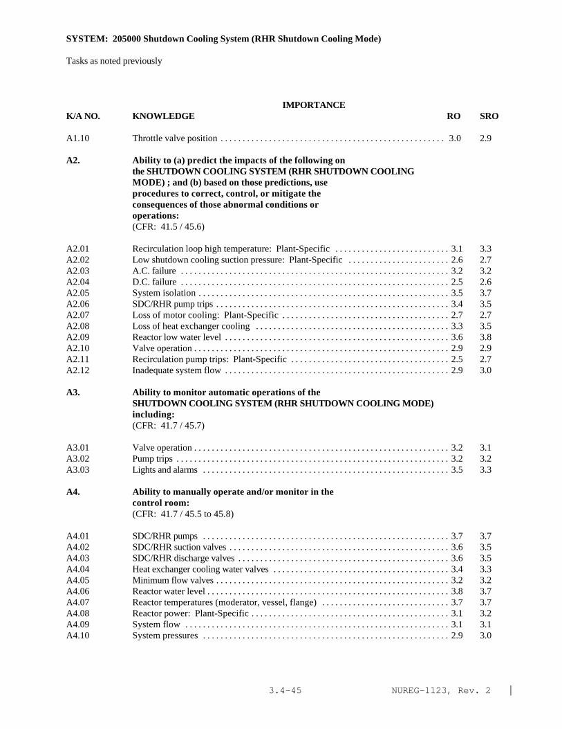
NUREG-1123, Rev. 2 |3.4-45
SYSTEM: 205000 Shutdown Cooling System (RHR Shutdown Cooling Mode)
Tasks as noted previously
IMPORTANCE K/A NO. KNOWLEDGE RO SRO
A1.10 Throttle valve position . . . . . . . . . . . . . . . . . . . . . . . . . . . . . . . . . . . . . . . . . . . . . . . . . . . 3.0 2.9
A2. Ability to (a) predict the impacts of the following onthe SHUTDOWN COOLING SYSTEM (RHR SHUTDOWN COOLINGMODE) ; and (b) based on those predictions, useprocedures to correct, control, or mitigate theconsequences of those abnormal conditions oroperations:(CFR: 41.5 / 45.6)
A2.01 Recirculation loop high temperature: Plant-Specific . . . . . . . . . . . . . . . . . . . . . . . . . . 3.1 3.3A2.02 Low shutdown cooling suction pressure: Plant-Specific . . . . . . . . . . . . . . . . . . . . . . . 2.6 2.7A2.03 A.C. failure . . . . . . . . . . . . . . . . . . . . . . . . . . . . . . . . . . . . . . . . . . . . . . . . . . . . . . . . . . . . . 3.2 3.2A2.04 D.C. failure . . . . . . . . . . . . . . . . . . . . . . . . . . . . . . . . . . . . . . . . . . . . . . . . . . . . . . . . . . . . . 2.5 2.6A2.05 System isolation . . . . . . . . . . . . . . . . . . . . . . . . . . . . . . . . . . . . . . . . . . . . . . . . . . . . . . . . . 3.5 3.7A2.06 SDC/RHR pump trips . . . . . . . . . . . . . . . . . . . . . . . . . . . . . . . . . . . . . . . . . . . . . . . . . . . . . 3.4 3.5A2.07 Loss of motor cooling: Plant-Specific . . . . . . . . . . . . . . . . . . . . . . . . . . . . . . . . . . . . . . 2.7 2.7A2.08 Loss of heat exchanger cooling . . . . . . . . . . . . . . . . . . . . . . . . . . . . . . . . . . . . . . . . . . . . 3.3 3.5A2.09 Reactor low water level . . . . . . . . . . . . . . . . . . . . . . . . . . . . . . . . . . . . . . . . . . . . . . . . . . . 3.6 3.8A2.10 Valve operation . . . . . . . . . . . . . . . . . . . . . . . . . . . . . . . . . . . . . . . . . . . . . . . . . . . . . . . . . . 2.9 2.9A2.11 Recirculation pump trips: Plant-Specific . . . . . . . . . . . . . . . . . . . . . . . . . . . . . . . . . . . . 2.5 2.7A2.12 Inadequate system flow . . . . . . . . . . . . . . . . . . . . . . . . . . . . . . . . . . . . . . . . . . . . . . . . . . . 2.9 3.0
A3. Ability to monitor automatic operations of theSHUTDOWN COOLING SYSTEM (RHR SHUTDOWN COOLING MODE)including:(CFR: 41.7 / 45.7)
A3.01 Valve operation . . . . . . . . . . . . . . . . . . . . . . . . . . . . . . . . . . . . . . . . . . . . . . . . . . . . . . . . . . 3.2 3.1A3.02 Pump trips . . . . . . . . . . . . . . . . . . . . . . . . . . . . . . . . . . . . . . . . . . . . . . . . . . . . . . . . . . . . . . 3.2 3.2A3.03 Lights and alarms . . . . . . . . . . . . . . . . . . . . . . . . . . . . . . . . . . . . . . . . . . . . . . . . . . . . . . . . 3.5 3.3
A4. Ability to manually operate and/or monitor in thecontrol room:(CFR: 41.7 / 45.5 to 45.8)
A4.01 SDC/RHR pumps . . . . . . . . . . . . . . . . . . . . . . . . . . . . . . . . . . . . . . . . . . . . . . . . . . . . . . . . 3.7 3.7A4.02 SDC/RHR suction valves . . . . . . . . . . . . . . . . . . . . . . . . . . . . . . . . . . . . . . . . . . . . . . . . . . 3.6 3.5A4.03 SDC/RHR discharge valves . . . . . . . . . . . . . . . . . . . . . . . . . . . . . . . . . . . . . . . . . . . . . . . . 3.6 3.5A4.04 Heat exchanger cooling water valves . . . . . . . . . . . . . . . . . . . . . . . . . . . . . . . . . . . . . . . . 3.4 3.3A4.05 Minimum flow valves . . . . . . . . . . . . . . . . . . . . . . . . . . . . . . . . . . . . . . . . . . . . . . . . . . . . . 3.2 3.2A4.06 Reactor water level . . . . . . . . . . . . . . . . . . . . . . . . . . . . . . . . . . . . . . . . . . . . . . . . . . . . . . . 3.8 3.7A4.07 Reactor temperatures (moderator, vessel, flange) . . . . . . . . . . . . . . . . . . . . . . . . . . . . . 3.7 3.7A4.08 Reactor power: Plant-Specific . . . . . . . . . . . . . . . . . . . . . . . . . . . . . . . . . . . . . . . . . . . . . 3.1 3.2A4.09 System flow . . . . . . . . . . . . . . . . . . . . . . . . . . . . . . . . . . . . . . . . . . . . . . . . . . . . . . . . . . . . 3.1 3.1A4.10 System pressures . . . . . . . . . . . . . . . . . . . . . . . . . . . . . . . . . . . . . . . . . . . . . . . . . . . . . . . . 2.9 3.0

NUREG-1123, Rev. 2 |3.4-46
SYSTEM: 205000 Shutdown Cooling System (RHR Shutdown Cooling Mode)
Tasks as noted previously
IMPORTANCE K/A NO. KNOWLEDGE RO SRO
A4.11 Heat exchanger cooling flow 3.2 3.2A4.12 Recirculation loop temperatures 3.4 3.4

NUREG-1123, Rev. 2 |3.5-1
3.5 Containment Integrity page
223001 Primary Containment System and Auxiliaries 3.5-3223002 Primary Containment Isolation System 3.5-8
/Nuclear Steam Supply Shut-Off290002 Reactor Vessel Internals 3.5-12219000 RHR/LPCI: Torus/Suppression Pool Cooling Mode 3.5-15226001 RHR/LPCI: Containment Spray System Mode 3.5-19230000 RHR/LPCI: Torus/Suppression Pool Spray Mode 3.5-23290001 Secondary Containment 3.5-28

NUREG-1123, Rev. 2 |3.5-2
This page left blank
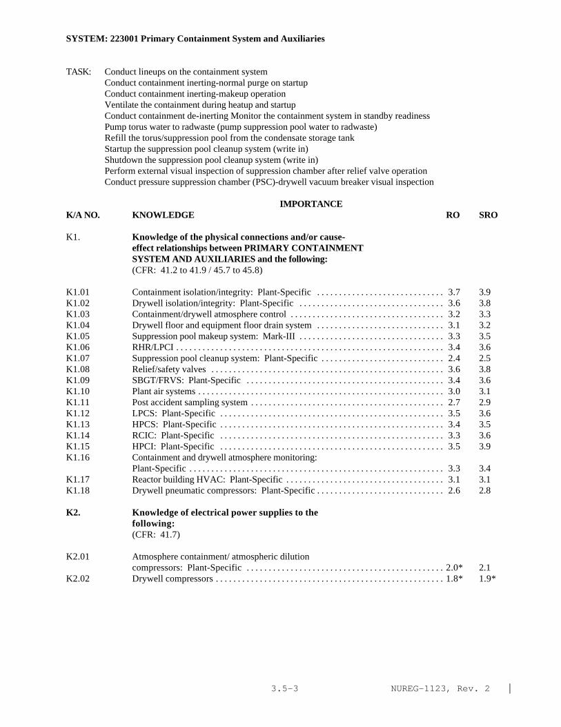
NUREG-1123, Rev. 2 |3.5-3
SYSTEM: 223001 Primary Containment System and Auxiliaries
TASK: Conduct lineups on the containment system Conduct containment inerting-normal purge on startup Conduct containment inerting-makeup operation Ventilate the containment during heatup and startup Conduct containment de-inerting Monitor the containment system in standby readiness Pump torus water to radwaste (pump suppression pool water to radwaste)Refill the torus/suppression pool from the condensate storage tankStartup the suppression pool cleanup system (write in) Shutdown the suppression pool cleanup system (write in) Perform external visual inspection of suppression chamber after relief valve operation Conduct pressure suppression chamber (PSC)-drywell vacuum breaker visual inspection
IMPORTANCE K/A NO. KNOWLEDGE RO SRO
K1. Knowledge of the physical connections and/or cause-effect relationships between PRIMARY CONTAINMENTSYSTEM AND AUXILIARIES and the following:(CFR: 41.2 to 41.9 / 45.7 to 45.8)
K1.01 Containment isolation/integrity: Plant-Specific . . . . . . . . . . . . . . . . . . . . . . . . . . . . . 3.7 3.9K1.02 Drywell isolation/integrity: Plant-Specific . . . . . . . . . . . . . . . . . . . . . . . . . . . . . . . . . 3.6 3.8K1.03 Containment/drywell atmosphere control . . . . . . . . . . . . . . . . . . . . . . . . . . . . . . . . . . . 3.2 3.3K1.04 Drywell floor and equipment floor drain system . . . . . . . . . . . . . . . . . . . . . . . . . . . . . 3.1 3.2K1.05 Suppression pool makeup system: Mark-III . . . . . . . . . . . . . . . . . . . . . . . . . . . . . . . . . 3.3 3.5K1.06 RHR/LPCI . . . . . . . . . . . . . . . . . . . . . . . . . . . . . . . . . . . . . . . . . . . . . . . . . . . . . . . . . . . . . 3.4 3.6K1.07 Suppression pool cleanup system: Plant-Specific . . . . . . . . . . . . . . . . . . . . . . . . . . . . 2.4 2.5K1.08 Relief/safety valves . . . . . . . . . . . . . . . . . . . . . . . . . . . . . . . . . . . . . . . . . . . . . . . . . . . . . 3.6 3.8K1.09 SBGT/FRVS: Plant-Specific . . . . . . . . . . . . . . . . . . . . . . . . . . . . . . . . . . . . . . . . . . . . . 3.4 3.6K1.10 Plant air systems . . . . . . . . . . . . . . . . . . . . . . . . . . . . . . . . . . . . . . . . . . . . . . . . . . . . . . . . 3.0 3.1K1.11 Post accident sampling system . . . . . . . . . . . . . . . . . . . . . . . . . . . . . . . . . . . . . . . . . . . . 2.7 2.9K1.12 LPCS: Plant-Specific . . . . . . . . . . . . . . . . . . . . . . . . . . . . . . . . . . . . . . . . . . . . . . . . . . . 3.5 3.6K1.13 HPCS: Plant-Specific . . . . . . . . . . . . . . . . . . . . . . . . . . . . . . . . . . . . . . . . . . . . . . . . . . . 3.4 3.5K1.14 RCIC: Plant-Specific . . . . . . . . . . . . . . . . . . . . . . . . . . . . . . . . . . . . . . . . . . . . . . . . . . . 3.3 3.6K1.15 HPCI: Plant-Specific . . . . . . . . . . . . . . . . . . . . . . . . . . . . . . . . . . . . . . . . . . . . . . . . . . . 3.5 3.9K1.16 Containment and drywell atmosphere monitoring:
Plant-Specific . . . . . . . . . . . . . . . . . . . . . . . . . . . . . . . . . . . . . . . . . . . . . . . . . . . . . . . . . . 3.3 3.4K1.17 Reactor building HVAC: Plant-Specific . . . . . . . . . . . . . . . . . . . . . . . . . . . . . . . . . . . . 3.1 3.1K1.18 Drywell pneumatic compressors: Plant-Specific . . . . . . . . . . . . . . . . . . . . . . . . . . . . . 2.6 2.8
K2. Knowledge of electrical power supplies to thefollowing:(CFR: 41.7)
K2.01 Atmosphere containment/ atmospheric dilutioncompressors: Plant-Specific . . . . . . . . . . . . . . . . . . . . . . . . . . . . . . . . . . . . . . . . . . . . . 2.0* 2.1
K2.02 Drywell compressors . . . . . . . . . . . . . . . . . . . . . . . . . . . . . . . . . . . . . . . . . . . . . . . . . . . . 1.8* 1.9*

NUREG-1123, Rev. 2 |3.5-4
SYSTEM: 223001 Primary Containment System and Auxiliaries
Tasks as noted previously
IMPORTANCE K/A NO. KNOWLEDGE RO SRO
K2.03 Pumpback compressors: Plant-Specific . . . . . . . . . . . . . . . . . . . . . . . . . . . . . . . . . . . . 1.8* 1.8*K2.04 Combustible gas mixing compressors: Mark-III . . . . . . . . . . . . . . . . . . . . . . . . . . . . . 2.0* 2.4K2.05 Hydrogen recombiners: Plant-Specific . . . . . . . . . . . . . . . . . . . . . . . . . . . . . . . . . . . . . 2.2* 2.4*K2.06 Hydrogen igniters: Plant-Specific . . . . . . . . . . . . . . . . . . . . . . . . . . . . . . . . . . . . . . . . . 2.0* 2.4K2.07 Containment atmosphere monitoring system . . . . . . . . . . . . . . . . . . . . . . . . . . . . . . . . 2.3* 2.6*K2.08 Containment cooling air handling units: Plant-
Specific . . . . . . . . . . . . . . . . . . . . . . . . . . . . . . . . . . . . . . . . . . . . . . . . . . . . . . . . . . . . . . . 2.7 3.0*K2.09 Drywell cooling fans: Plant-Specific . . . . . . . . . . . . . . . . . . . . . . . . . . . . . . . . . . . . . . 2.7 2.9*K2.10 Drywell chillers: Plant-Specific . . . . . . . . . . . . . . . . . . . . . . . . . . . . . . . . . . . . . . . . . . 2.7 2.9*
K3. Knowledge of the effect that a loss or malfunction ofthe PRIMARY CONTAINMENT SYSTEM AND AUXILIARIES willhave on following:(CFR: 41.7 / 45.4)
K3.01 Secondary containment . . . . . . . . . . . . . . . . . . . . . . . . . . . . . . . . . . . . . . . . . . . . . . . . . . 3.6 3.8K3.02 Containment/drywell temperature: Plant-Specific . . . . . . . . . . . . . . . . . . . . . . . . . . . . 3.3 3.4K3.03 Containment/drywell pressure: Plant-Specific . . . . . . . . . . . . . . . . . . . . . . . . . . . . . . . 3.4 3.5K3.04 Containment/drywell hydrogen gas concentration . . . . . . . . . . . . . . . . . . . . . . . . . . . . 3.3 3.5K3.05 Containment/drywell oxygen gas concentration . . . . . . . . . . . . . . . . . . . . . . . . . . . . . . 3.1 3.2K3.06 Differential pressure between secondary and primary
containment . . . . . . . . . . . . . . . . . . . . . . . . . . . . . . . . . . . . . . . . . . . . . . . . . . . . . . . . . . . . 3.3 3.6K3.07 Differential pressure between suppression pool and
drywell/containment . . . . . . . . . . . . . . . . . . . . . . . . . . . . . . . . . . . . . . . . . . . . . . . . . . . . . 3.1 3.2K3.08 Pneumatically operated valves internal to
containment/drywell: Plant-Specific . . . . . . . . . . . . . . . . . . . . . . . . . . . . . . . . . . . . . . . 2.7 2.9K3.09 Nuclear boiler instrumentation . . . . . . . . . . . . . . . . . . . . . . . . . . . . . . . . . . . . . . . . . . . . 2.8 3.1K3.10 Containment/drywell moisture content . . . . . . . . . . . . . . . . . . . . . . . . . . . . . . . . . . . . . 2.4 2.6
K4. Knowledge of PRIMARY CONTAINMENT SYSTEM ANDAUXILIARIES design feature(s) and/or interlocks whichprovide for the following:(CFR: 41.7)
K4.01 Allows for absorption of the energy released during aLOCA . . . . . . . . . . . . . . . . . . . . . . . . . . . . . . . . . . . . . . . . . . . . . . . . . . . . . . . . . . . . . . . . . 3.7 3.8
K4.02 Contains fission products after a LOCA . . . . . . . . . . . . . . . . . . . . . . . . . . . . . . . . . . . . 3.6 3.7K4.03 Containment/drywell isolation . . . . . . . . . . . . . . . . . . . . . . . . . . . . . . . . . . . . . . . . . . . . 3.7 3.8K4.04 Prevents hydrogen from reaching an explosive mixture . . . . . . . . . . . . . . . . . . . . . . . . 3.5 3.8K4.05 Maintains proper suppression pool to drywell
differential pressure . . . . . . . . . . . . . . . . . . . . . . . . . . . . . . . . . . . . . . . . . . . . . . . . . . . . . 2.9 3.1K4.06 Maintains proper containment/secondary containment to
drywell differential pressure . . . . . . . . . . . . . . . . . . . . . . . . . . . . . . . . . . . . . . . . . . . . . . 3.1 3.3K4.07 Prevents localized heating of suppression pool (SRV
steam quenchers) . . . . . . . . . . . . . . . . . . . . . . . . . . . . . . . . . . . . . . . . . . . . . . . . . . . . . . . 3.1 3.3

NUREG-1123, Rev. 2 |3.5-5
SYSTEM: 223001 Primary Containment System and Auxiliaries
Tasks as noted previously
IMPORTANCE K/A NO. KNOWLEDGE RO SRO
K5. Knowledge of the operational implications of thefollowing concepts as they apply to PRIMARYCONTAINMENT SYSTEM AND AUXILIARIES :(CFR: 41.5 / 45.3)
K5.01 Vacuum breaker/relief operation . . . . . . . . . . . . . . . . . . . . . . . . . . . . . . . . . . . . . . . . . . . 3.1 3.3K5.02 Guard pipe operation: Mark-III . . . . . . . . . . . . . . . . . . . . . . . . . . . . . . . . . . . . . . . . . . . . 2.3 2.4K5.03 Down comer operation . . . . . . . . . . . . . . . . . . . . . . . . . . . . . . . . . . . . . . . . . . . . . . . . . . . 2.8 2.9K5.04 Horizontal vent operation: Mark-III . . . . . . . . . . . . . . . . . . . . . . . . . . . . . . . . . . . . . . . . . 2.4 2.6K5.05 Hydrogen recombiner operation: Plant-Specific . . . . . . . . . . . . . . . . . . . . . . . . . . . . . . 2.8 3.0K5.06 Hydrogen igniter operation: Plant-Specific . . . . . . . . . . . . . . . . . . . . . . . . . . . . . . . . . . 2.8 2.9K5.07 Suppression pool clean-up: Plant-Specific . . . . . . . . . . . . . . . . . . . . . . . . . . . . . . . . . . . 2.3 2.4K5.08 Pressure measurement . . . . . . . . . . . . . . . . . . . . . . . . . . . . . . . . . . . . . . . . . . . . . . . . . . . . 2.7 2.8K5.09 Hydrogen production mechanisms . . . . . . . . . . . . . . . . . . . . . . . . . . . . . . . . . . . . . . . . . . 2.6 2.9*K5.10 Hydrogen combustibility versus hydrogen concentration
and oxygen concentration . . . . . . . . . . . . . . . . . . . . . . . . . . . . . . . . . . . . . . . . . . . . . . . . . 2.9 3.1K5.11 Temperature measurement . . . . . . . . . . . . . . . . . . . . . . . . . . . . . . . . . . . . . . . . . . . . . . . . 2.7 2.7K5.12 Hydrogen concentration measurement . . . . . . . . . . . . . . . . . . . . . . . . . . . . . . . . . . . . . . . 2.7 2.8K5.13 Oxygen concentration measurement: Plant-Specific . . . . . . . . . . . . . . . . . . . . . . . . . . . 2.7 2.8K5.14 Differential pressure measurement . . . . . . . . . . . . . . . . . . . . . . . . . . . . . . . . . . . . . . . . . 2.6 2.8*K5.15 Moisture content measurement: Plant-Specific . . . . . . . . . . . . . . . . . . . . . . . . . . . . . . . 2.4 2.6
K6. Knowledge of the effect that a loss or malfunction ofthe following will have on the PRIMARY CONTAINMENTSYSTEM AND AUXILIARIES :(CFR: 41.7 / 45.7)
K6.01 Drywell cooling . . . . . . . . . . . . . . . . . . . . . . . . . . . . . . . . . . . . . . . . . . . . . . . . . . . . . . . . . 3.6 3.8K6.02 Containment cooling: Mark-III . . . . . . . . . . . . . . . . . . . . . . . . . . . . . . . . . . . . . . . . . . . . 3.5 3.6K6.03 Suppression pool makeup: Plant-Specific . . . . . . . . . . . . . . . . . . . . . . . . . . . . . . . . . . . 2.8 3.1K6.04 Combustible gas mixing: Plant-Specific . . . . . . . . . . . . . . . . . . . . . . . . . . . . . . . . . . . . . 2.8 2.8K6.05 Hydrogen recombiner: Plant-Specific . . . . . . . . . . . . . . . . . . . . . . . . . . . . . . . . . . . . . . 3.1 3.3K6.06 Backup hydrogen purge: Plant-Specific . . . . . . . . . . . . . . . . . . . . . . . . . . . . . . . . . . . . . 2.8 3.0K6.07 Hydrogen igniter system: Plant-Specific . . . . . . . . . . . . . . . . . . . . . . . . . . . . . . . . . . . . 3.0 3.1K6.08 Containment atmospheric control . . . . . . . . . . . . . . . . . . . . . . . . . . . . . . . . . . . . . . . . . . 3.3 3.4K6.09 Drywell vacuum relief system . . . . . . . . . . . . . . . . . . . . . . . . . . . . . . . . . . . . . . . . . . . . . . 3.4 3.6K6.10 Containment vacuum relief system: Mark-III . . . . . . . . . . . . . . . . . . . . . . . . . . . . . . . . . 3.0 3.2K6.11 A.C. electrical distribution . . . . . . . . . . . . . . . . . . . . . . . . . . . . . . . . . . . . . . . . . . . . . . . . 3.0 3.2K6.12 D.C. electrical distribution . . . . . . . . . . . . . . . . . . . . . . . . . . . . . . . . . . . . . . . . . . . . . . . . 2.7 3.0K6.13 Applicable plant air system/ nitrogen make-up system. . . . . . . . . . . . . . . . . . . . . . . . . . 3.2 3.4K6.14 RHR/LPCI . . . . . . . . . . . . . . . . . . . . . . . . . . . . . . . . . . . . . . . . . . . . . . . . . . . . . . . . . . . . . . 3.6 3.8

NUREG-1123, Rev. 2 |3.5-6
SYSTEM: 223001 Primary Containment System and Auxiliaries
Tasks as noted previously
IMPORTANCE K/A NO. KNOWLEDGE RO SRO
ABILITY
Al. Ability to predict and/or monitor changes inparameters associated with operating the PRIMARYCONTAINMENT SYSTEM AND AUXILIARIES controls including:(CFR: 41.5 / 45.5)
A1.01 Drywell temperature 3.5 3.6A1.02 Drywell pressure 3.6 3.7A1.03 Containment pressure: Mark-III 3.6 3.8A1.04 Containment temperature: Mark-III 3.3 3.4A1.05 Hydrogen concentration 3.1 3.3A1.06 Oxygen concentration 3.1 3.3A1.07 Drywell/suppression chamber differential pressure
(drywell to containment building): Plant-Specific 3.2 3.4A1.08 Suppression pool level 3.5 3.6A1.09 Suppression pool temperature 3.5 3.6A1.10 Drywell leak detection system: Plant-Specific 3.4 3.6A1.11 Reactor building to suppression chamber differential
pressure: Plant-Specific 3.1 3.2A1.12 Moisture concentration 2.5 2.6
A2. Ability to (a) predict the impacts of the following onthe PRIMARY CONTAINMENT SYSTEM AND AUXILIARIES ; and(b) based on those predictions, use procedures tocorrect, control, or mitigate the consequences ofthose abnormal conditions or operations:
(CFR: 41.5 / 45.6)
A2.01 Loss of coolant accident . . . . . . . . . . . . . . . . . . . . . . . . . . . . . . . . . . . . . . . . . . . . . . . . . 4.3* 4.4*A2.02 Steam bypass of suppression pool . . . . . . . . . . . . . . . . . . . . . . . . . . . . . . . . . . . . . . . . . 3.9 4.1A2.03 Safety/relief valve leaking or stuck open . . . . . . . . . . . . . . . . . . . . . . . . . . . . . . . . . . . 4.0 4.2*A2.04 High containment/drywell hydrogen concentration . . . . . . . . . . . . . . . . . . . . . . . . . . . 3.7 3.8A2.05 High containment/drywell oxygen concentration . . . . . . . . . . . . . . . . . . . . . . . . . . . . . 3.5 3.6A2.06 High containment pressure: Mark-III . . . . . . . . . . . . . . . . . . . . . . . . . . . . . . . . . . . . . . 4.1* 4.1*A2.07 High drywell pressure . . . . . . . . . . . . . . . . . . . . . . . . . . . . . . . . . . . . . . . . . . . . . . . . . . . 4.2* 4.3*A2.08 Compressor trips (loss of air): Plant-Specific . . . . . . . . . . . . . . . . . . . . . . . . . . . . . . 3.1 3.1A2.09 Vacuum breaker malfunction . . . . . . . . . . . . . . . . . . . . . . . . . . . . . . . . . . . . . . . . . . . . . 3.4 3.6A2.10 High drywell temperature . . . . . . . . . . . . . . . . . . . . . . . . . . . . . . . . . . . . . . . . . . . . . . . . 3.6 3.8A2.11 Abnormal suppression pool level . . . . . . . . . . . . . . . . . . . . . . . . . . . . . . . . . . . . . . . . . . 3.6 3.8A2.12 Abnormal suppression pool temperature . . . . . . . . . . . . . . . . . . . . . . . . . . . . . . . . . . . 3.7 3.8A2.13 High containment temperature: Mark-III . . . . . . . . . . . . . . . . . . . . . . . . . . . . . . . . . . . 3.3 3.4A2.14 Low containment to annulus pressure: Mark-III . . . . . . . . . . . . . . . . . . . . . . . . . . . . . 3.4 3.4

NUREG-1123, Rev. 2 |3.5-7
SYSTEM: 223001 Primary Containment System and Auxiliaries
Tasks as noted previously
IMPORTANCE K/A NO. ABILITY RO SRO
A3. Ability to monitor automatic operations of the PRIMARYCONTAINMENT SYSTEM AND AUXILIARIES including:(CFR: 41.7 / 45.7)
A3.01 Suppression pool level . . . . . . . . . . . . . . . . . . . . . . . . . . . . . . . . . . . . . . . . . . . . . . . . . . 3.4 3.5A3.02 Vacuum breaker/relief valve operation . . . . . . . . . . . . . . . . . . . . . . . . . . . . . . . . . . . . . 3.4 3.4A3.03 System indicating light and alarms . . . . . . . . . . . . . . . . . . . . . . . . . . . . . . . . . . . . . . . . . 3.4 3.3A3.04 Containment/drywell response during LOCA . . . . . . . . . . . . . . . . . . . . . . . . . . . . . . . . 4.2* 4.3* |A3.05 Drywell pressure . . . . . . . . . . . . . . . . . . . . . . . . . . . . . . . . . . . . . . . . . . . . . . . . . . . . . . . 4.3* 4.3* |A3.06 Drywell/suppression chamber differential pressure:
Mark-I,II . . . . . . . . . . . . . . . . . . . . . . . . . . . . . . . . . . . . . . . . . . . . . . . . . . . . . . . . . . . . . . 3.4 3.3A3.07 Containment/drywell differential pressure: Mark-III . . . . . . . . . . . . . . . . . . . . . . . . . . 3.6 3.6
A4. Ability to manually operate and/or monitor in thecontrol room:(CFR: 41.7 / 45.5 to 45.8)
A4.01 Containment relief valves: Mark-III . . . . . . . . . . . . . . . . . . . . . . . . . . . . . . . . . . . . . . . . 3.5 3.5A4.02 ACAD compressors: Plant-Specific . . . . . . . . . . . . . . . . . . . . . . . . . . . . . . . . . . . . . . . 2.6 2.6A4.03 Air dilution valves to drywell and suppression pool:
Plant-Specific . . . . . . . . . . . . . . . . . . . . . . . . . . . . . . . . . . . . . . . . . . . . . . . . . . . . . . . . . . 3.4 3.4A4.04 Containment/drywell hydrogen concentration . . . . . . . . . . . . . . . . . . . . . . . . . . . . . . . . 3.5 3.6A4.05 Containment/drywell oxygen concentration . . . . . . . . . . . . . . . . . . . . . . . . . . . . . . . . . 3.6 3.6A4.06 Containment pressure: Mark-III . . . . . . . . . . . . . . . . . . . . . . . . . . . . . . . . . . . . . . . . . . . 4.0* 4.0*A4.07 Drywell pressure . . . . . . . . . . . . . . . . . . . . . . . . . . . . . . . . . . . . . . . . . . . . . . . . . . . . . . . 4.2* 4.1A4.08 System indicating lights and alarms . . . . . . . . . . . . . . . . . . . . . . . . . . . . . . . . . . . . . . . . 3.4 3.3A4.09 SPDS/CRIDS/ERIS/GDS: Plant-Specific . . . . . . . . . . . . . . . . . . . . . . . . . . . . . . . . . . . 2.5 2.9*A4.10 Drywell nitrogen makeup: Mark-I,II . . . . . . . . . . . . . . . . . . . . . . . . . . . . . . . . . . . . . . . 3.2 3.2A4.11 Drywell pneumatics . . . . . . . . . . . . . . . . . . . . . . . . . . . . . . . . . . . . . . . . . . . . . . . . . . . . . 3.1 3.0A4.12 Drywell coolers/chillers . . . . . . . . . . . . . . . . . . . . . . . . . . . . . . . . . . . . . . . . . . . . . . . . . 3.5 3.6A4.13 Hydrogen recombiners: Plant-Specific . . . . . . . . . . . . . . . . . . . . . . . . . . . . . . . . . . . . . 3.4 3.4A4.14 Hydrogen igniters: Plant-Specific . . . . . . . . . . . . . . . . . . . . . . . . . . . . . . . . . . . . . . . . . 3.7 3.7

NUREG-1123, Rev. 2 |3.5-8
SYSTEM: 223002 Primary Containment Isolation System/Nuclear Steam Supply Shut-Off
TASK: Conduct lineups on the containment systemMonitor the containment system in standby readinessPerform primary containment isolation valve simulated automatic initiation and closure testConduct reactor building isolation logic system functional testPerform drywell isolation, atmosphere control, and sump drain valves logic system testPerform drywell isolation valves, atmosphere control valves, sump drain valves simulated auto actuationtest
IMPORTANCE K/A NO. KNOWLEDGE RO SRO
K1. Knowledge of the physical connections and/or cause-effect relationships between PRIMARY CONTAINMENTISOLATION SYSTEM/NUCLEAR STEAM SUPPLY SHUT-OFF and thefollowing:(CFR: 41.2 to 41.9 / 45.7 to 45.8)
K1.01 Main steam system . . . . . . . . . . . . . . . . . . . . . . . . . . . . . . . . . . . . . . . . . . . . . . . . . . . . . . 3.8 3.9K1.02 Reactor water cleanup . . . . . . . . . . . . . . . . . . . . . . . . . . . . . . . . . . . . . . . . . . . . . . . . . . . 3.3 3.5K1.03 Plant ventilation . . . . . . . . . . . . . . . . . . . . . . . . . . . . . . . . . . . . . . . . . . . . . . . . . . . . . . . . 3.0 3.2K1.04 High pressure coolant injection: Plant-Specific . . . . . . . . . . . . . . . . . . . . . . . . . . . . . 3.5 3.8K1.05 Isolation Condenser: Plant-Specific . . . . . . . . . . . . . . . . . . . . . . . . . . . . . . . . . . . . . . . 3.8 3.8K1.06 Recirculation system . . . . . . . . . . . . . . . . . . . . . . . . . . . . . . . . . . . . . . . . . . . . . . . . . . . . 2.9 3.2K1.07 Reactor core isolation cooling; Plant-Specific . . . . . . . . . . . . . . . . . . . . . . . . . . . . . . . 3.4 3.6K1.08 Shutdown cooling system/RHR . . . . . . . . . . . . . . . . . . . . . . . . . . . . . . . . . . . . . . . . . . . 3.4 3.5K1.09 Reactor vessel head spray: Plant-Specific . . . . . . . . . . . . . . . . . . . . . . . . . . . . . . . . . . 3.0 3.2K1.10 Containment ventilation . . . . . . . . . . . . . . . . . . . . . . . . . . . . . . . . . . . . . . . . . . . . . . . . . . 3.1 3.2K1.11 Containment atmosphere sampling . . . . . . . . . . . . . . . . . . . . . . . . . . . . . . . . . . . . . . . . . 2.9 3.2K1.12 Standby gas treatment system . . . . . . . . . . . . . . . . . . . . . . . . . . . . . . . . . . . . . . . . . . . . . 3.1 3.3K1.13 Traversing in-core probe system . . . . . . . . . . . . . . . . . . . . . . . . . . . . . . . . . . . . . . . . . . . 2.7 2.9K1.14 Containment drainage system . . . . . . . . . . . . . . . . . . . . . . . . . . . . . . . . . . . . . . . . . . . . . 2.8 3.1K1.15 High pressure core spray : Plant-Specific . . . . . . . . . . . . . . . . . . . . . . . . . . . . . . . . . . 3.4 3.4K1.16 Process computer . . . . . . . . . . . . . . . . . . . . . . . . . . . . . . . . . . . . . . . . . . . . . . . . . . . . . . . 2.1* 2.2*|K1.17 SPDS/ERIS/CRIDS/GDS: Plant-Specific . . . . . . . . . . . . . . . . . . . . . . . . . . . . . . . . . . . 2.4 2.6K1.18 Reactor building drainage system: Plant-Specific . . . . . . . . . . . . . . . . . . . . . . . . . . . . 2.5 2.6K1.19 Component cooling water systems . . . . . . . . . . . . . . . . . . . . . . . . . . . . . . . . . . . . . . . . . 2.7 2.9K1.20 A.C. distribution: Plant-Specific . . . . . . . . . . . . . . . . . . . . . . . . . . . . . . . . . . . . . . . . . . 2.8 3.0K1.21 Circulating water: Plant-Specific . . . . . . . . . . . . . . . . . . . . . . . . . . . . . . . . . . . . . . . . . . 2.2* 2.3*|K1.22 Containment nitrogen inerting system: Plant-Specific. . . . . . . . . . . . . . . . . . . . . . . . . 2.8 3.0K1.23 River water makeup: Plant-Specific . . . . . . . . . . . . . . . . . . . . . . . . . . . . . . . . . . . . . . . 2.0* 2.1
K2. Knowledge of electrical power supplies to thefollowing:(CFR: 41.7)
K2.01 Logic power supplies . . . . . . . . . . . . . . . . . . . . . . . . . . . . . . . . . . . . . . . . . . . . . . . . . . . . 2.4* 2.7*|

NUREG-1123, Rev. 2 |3.5-9
SYSTEM: 223002 Primary Containment Isolation System/Nuclear Steam Supply Shut-Off
Tasks as noted previously
IMPORTANCE K/A NO. KNOWLEDGE RO SRO
K3. Knowledge of the effect that a loss or malfunction ofthe PRIMARY CONTAINMENT ISOLATION SYSTEM/NUCLEAR STEAMSUPPLY SHUT-OFF will have on following:(CFR: 41.7 / 45.4)
K3.01 Reactor water level . . . . . . . . . . . . . . . . . . . . . . . . . . . . . . . . . . . . . . . . . . . . . . . . . . . . . . 3.7 3.7K3.02 Fuel cladding temperature . . . . . . . . . . . . . . . . . . . . . . . . . . . . . . . . . . . . . . . . . . . . . . . . 3.6 3.7K3.03 †Off-site radioactive release rates . . . . . . . . . . . . . . . . . . . . . . . . . . . . . . . . . . . . . . . . . 3.6 3.8K3.04 Reactor building radiation level . . . . . . . . . . . . . . . . . . . . . . . . . . . . . . . . . . . . . . . . . . . 3.4 3.6K3.05 Drainage sump levels . . . . . . . . . . . . . . . . . . . . . . . . . . . . . . . . . . . . . . . . . . . . . . . . . . . . 2.7 2.8K3.06 Turbine building radiation . . . . . . . . . . . . . . . . . . . . . . . . . . . . . . . . . . . . . . . . . . . . . . . . 2.8 2.9K3.07 Reactor pressure . . . . . . . . . . . . . . . . . . . . . . . . . . . . . . . . . . . . . . . . . . . . . . . . . . . . . . . . 3.7 3.8K3.08 Reactor vessel temperature . . . . . . . . . . . . . . . . . . . . . . . . . . . . . . . . . . . . . . . . . . . . . . . 3.4 3.5K3.09 Main steam system . . . . . . . . . . . . . . . . . . . . . . . . . . . . . . . . . . . . . . . . . . . . . . . . . . . . . . 3.4 3.6K3.10 Reactor water cleanup . . . . . . . . . . . . . . . . . . . . . . . . . . . . . . . . . . . . . . . . . . . . . . . . . . . 2.9 3.1K3.11 Plant ventilation . . . . . . . . . . . . . . . . . . . . . . . . . . . . . . . . . . . . . . . . . . . . . . . . . . . . . . . . 2.8 2.9K3.12 High pressure coolant injection: Plant-Specific . . . . . . . . . . . . . . . . . . . . . . . . . . . . . 3.6 3.6K3.13 Isolation Condenser: Plant-Specific . . . . . . . . . . . . . . . . . . . . . . . . . . . . . . . . . . . . . . . 3.7 3.7K3.14 Recirculation system: Plant-Specific . . . . . . . . . . . . . . . . . . . . . . . . . . . . . . . . . . . . . . 3.0 3.0K3.15 Reactor core isolation cooling: Plant-Specific . . . . . . . . . . . . . . . . . . . . . . . . . . . . . . 3.4 3.5K3.16 Shutdown cooling system/RHR . . . . . . . . . . . . . . . . . . . . . . . . . . . . . . . . . . . . . . . . . . . 3.2 3.3K3.17 Reactor vessel head spray: Plant-Specific . . . . . . . . . . . . . . . . . . . . . . . . . . . . . . . . . . 2.8 2.9K3.18 Containment ventilation . . . . . . . . . . . . . . . . . . . . . . . . . . . . . . . . . . . . . . . . . . . . . . . . . . 3.0 3.1K3.19 Containment atmosphere sampling . . . . . . . . . . . . . . . . . . . . . . . . . . . . . . . . . . . . . . . . . 2.8 3.0K3.20 Standby gas treatment system . . . . . . . . . . . . . . . . . . . . . . . . . . . . . . . . . . . . . . . . . . . . . 3.3 3.4K3.21 Traversing in-core probe system . . . . . . . . . . . . . . . . . . . . . . . . . . . . . . . . . . . . . . . . . . . 2.6 2.7K3.22 Containment drainage system . . . . . . . . . . . . . . . . . . . . . . . . . . . . . . . . . . . . . . . . . . . . . 2.5 2.6K3.23 High pressure core spray : Plant-Specific . . . . . . . . . . . . . . . . . . . . . . . . . . . . . . . . . . 3.6 3.6K3.24 Reactor building drainage system . . . . . . . . . . . . . . . . . . . . . . . . . . . . . . . . . . . . . . . . . . 2.4 2.6K3.25 Component cooling water systems . . . . . . . . . . . . . . . . . . . . . . . . . . . . . . . . . . . . . . . . . 2.3 2.3K3.26 A.C. distribution . . . . . . . . . . . . . . . . . . . . . . . . . . . . . . . . . . . . . . . . . . . . . . . . . . . . . . . . 2.1* 2.2*K3.27 Circulating water . . . . . . . . . . . . . . . . . . . . . . . . . . . . . . . . . . . . . . . . . . . . . . . . . . . . . . . 1.8* 1.8*K3.28 Containment nitrogen inerting system . . . . . . . . . . . . . . . . . . . . . . . . . . . . . . . . . . . . . . 2.7 2.8K3.29 River water makeup . . . . . . . . . . . . . . . . . . . . . . . . . . . . . . . . . . . . . . . . . . . . . . . . . . . . . 1.8* 1.8*
K4. Knowledge of PRIMARY CONTAINMENT ISOLATIONSYSTEM/NUCLEAR STEAM SUPPLY SHUT-OFF design feature(s)and/or interlocks which provide for the following:(CFR: 41.7)
K4.01 Redundancy . . . . . . . . . . . . . . . . . . . . . . . . . . . . . . . . . . . . . . . . . . . . . . . . . . . . . . . . . . . . 3.0 3.2K4.02 Testability . . . . . . . . . . . . . . . . . . . . . . . . . . . . . . . . . . . . . . . . . . . . . . . . . . . . . . . . . . . . . 2.7 2.9K4.03 Manual initiation capability: Plant-Specific . . . . . . . . . . . . . . . . . . . . . . . . . . . . . . . . . 3.5 3.6K4.04 †Automatic bypassing of selected isolations during
specified plant conditions . . . . . . . . . . . . . . . . . . . . . . . . . . . . . . . . . . . . . . . . . . . . . . . . 3.2 3.6

NUREG-1123, Rev. 2 |3.5-10
SYSTEM: 223002 Primary Containment Isolation System/Nuclear Steam Supply Shut-Off
Tasks as noted previously
IMPORTANCE K/A NO. KNOWLEDGE RO SRO
K4.05 Single failures will not impair the function abilityof the system . . . . . . . . . . . . . . . . . . . . . . . . . . . . . . . . . . . . . . . . . . . . . . . . . . . . . . . . . . . 2.9 3.1
K4.06 Once initiated, system reset requires deliberateoperator action . . . . . . . . . . . . . . . . . . . . . . . . . . . . . . . . . . . . . . . . . . . . . . . . . . . . . . . . . 3.4 3.5
K4.07 Physical separation of system components (to preventlocalized environmental factors, electrical faults,and physical events from impairing system response) . . . . . . . . . . . . . . . . . . . . . . . . . 2.8 2.9
K4.08 †Manual defeating of selected isolations duringspecified emergency conditions . . . . . . . . . . . . . . . . . . . . . . . . . . . . . . . . . . . . . . . . . . . 3.3 3.7
K5. Knowledge of the operational implications of thefollowing concepts as they apply to PRIMARYCONTAINMENT ISOLATION SYSTEM/NUCLEAR STEAM SUPPLYSHUT-OFF :(CFR: 41.5 / 45.3)
None|
K6. Knowledge of the effect that a loss or malfunction ofthe following will have on the PRIMARY CONTAINMENTISOLATION SYSTEM/NUCLEAR STEAM SUPPLY SHUT-OFF :(CFR: 41.7 / 45.7)
K6.01 A.C. electrical distribution . . . . . . . . . . . . . . . . . . . . . . . . . . . . . . . . . . . . . . . . . . . . . . . 3.1 3.3K6.02 D.C. electrical distribution . . . . . . . . . . . . . . . . . . . . . . . . . . . . . . . . . . . . . . . . . . . . . . . 3.0 3.2K6.03 Process radiation monitoring system . . . . . . . . . . . . . . . . . . . . . . . . . . . . . . . . . . . . . . . 2.9 3.1K6.04 Nuclear boiler instrumentation . . . . . . . . . . . . . . . . . . . . . . . . . . . . . . . . . . . . . . . . . . . . 3.3 3.5K6.05 Containment instrumentation . . . . . . . . . . . . . . . . . . . . . . . . . . . . . . . . . . . . . . . . . . . . . 3.0 3.3K6.06 Various process instrumentation . . . . . . . . . . . . . . . . . . . . . . . . . . . . . . . . . . . . . . . . . . 2.8 2.9K6.07 Essential A.C. power . . . . . . . . . . . . . . . . . . . . . . . . . . . . . . . . . . . . . . . . . . . . . . . . . . . . 3.2 3.3K6.08 Reactor protection system . . . . . . . . . . . . . . . . . . . . . . . . . . . . . . . . . . . . . . . . . . . . . . . 3.5 3.7
ABILITY
A1. Ability to predict and/or monitor changes inparameters associated with operating the PRIMARYCONTAINMENT ISOLATION SYSTEM/NUCLEAR STEAM SUPPLYSHUT-OFF controls including:(CFR: 41.5 / 45.5)
A1.01 System indicating lights and alarms . . . . . . . . . . . . . . . . . . . . . . . . . . . . . . . . . . . . . . . . 3.5 3.5A1.02 Valve closures . . . . . . . . . . . . . . . . . . . . . . . . . . . . . . . . . . . . . . . . . . . . . . . . . . . . . . . . . . 3.7 3.7A1.03 SPDS/ERIS/CRIDS/GDS: Plant-Specific . . . . . . . . . . . . . . . . . . . . . . . . . . . . . . . . . . . 2.5* 2.8*A1.04 Individual system relay status . . . . . . . . . . . . . . . . . . . . . . . . . . . . . . . . . . . . . . . . . . . . . 2.6 2.8
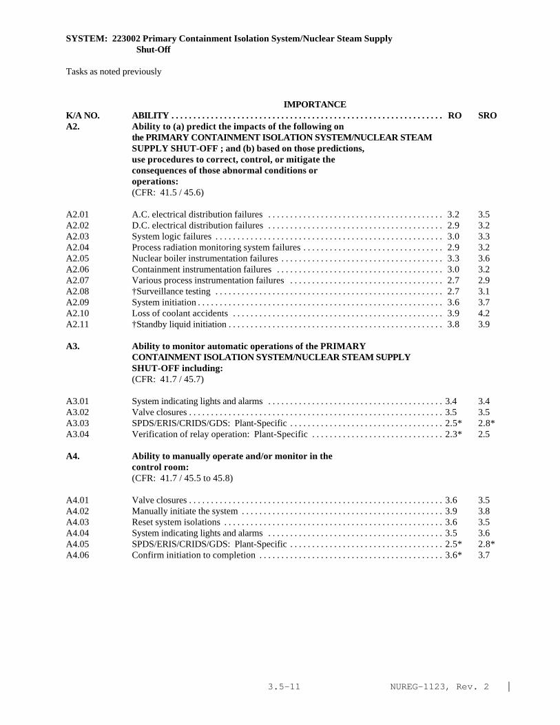
NUREG-1123, Rev. 2 |3.5-11
SYSTEM: 223002 Primary Containment Isolation System/Nuclear Steam Supply Shut-Off
Tasks as noted previously
IMPORTANCE K/A NO. ABILITY . . . . . . . . . . . . . . . . . . . . . . . . . . . . . . . . . . . . . . . . . . . . . . . . . . . . . . . . . . . . . . RO SROA2. Ability to (a) predict the impacts of the following on
the PRIMARY CONTAINMENT ISOLATION SYSTEM/NUCLEAR STEAMSUPPLY SHUT-OFF ; and (b) based on those predictions,use procedures to correct, control, or mitigate theconsequences of those abnormal conditions oroperations:(CFR: 41.5 / 45.6)
A2.01 A.C. electrical distribution failures . . . . . . . . . . . . . . . . . . . . . . . . . . . . . . . . . . . . . . . . 3.2 3.5A2.02 D.C. electrical distribution failures . . . . . . . . . . . . . . . . . . . . . . . . . . . . . . . . . . . . . . . . 2.9 3.2A2.03 System logic failures . . . . . . . . . . . . . . . . . . . . . . . . . . . . . . . . . . . . . . . . . . . . . . . . . . . . 3.0 3.3A2.04 Process radiation monitoring system failures . . . . . . . . . . . . . . . . . . . . . . . . . . . . . . . . 2.9 3.2A2.05 Nuclear boiler instrumentation failures . . . . . . . . . . . . . . . . . . . . . . . . . . . . . . . . . . . . . 3.3 3.6A2.06 Containment instrumentation failures . . . . . . . . . . . . . . . . . . . . . . . . . . . . . . . . . . . . . . 3.0 3.2A2.07 Various process instrumentation failures . . . . . . . . . . . . . . . . . . . . . . . . . . . . . . . . . . . 2.7 2.9A2.08 †Surveillance testing . . . . . . . . . . . . . . . . . . . . . . . . . . . . . . . . . . . . . . . . . . . . . . . . . . . . 2.7 3.1A2.09 System initiation . . . . . . . . . . . . . . . . . . . . . . . . . . . . . . . . . . . . . . . . . . . . . . . . . . . . . . . . 3.6 3.7A2.10 Loss of coolant accidents . . . . . . . . . . . . . . . . . . . . . . . . . . . . . . . . . . . . . . . . . . . . . . . . 3.9 4.2A2.11 †Standby liquid initiation . . . . . . . . . . . . . . . . . . . . . . . . . . . . . . . . . . . . . . . . . . . . . . . . . 3.8 3.9
A3. Ability to monitor automatic operations of the PRIMARYCONTAINMENT ISOLATION SYSTEM/NUCLEAR STEAM SUPPLYSHUT-OFF including:(CFR: 41.7 / 45.7)
A3.01 System indicating lights and alarms . . . . . . . . . . . . . . . . . . . . . . . . . . . . . . . . . . . . . . . . 3.4 3.4A3.02 Valve closures . . . . . . . . . . . . . . . . . . . . . . . . . . . . . . . . . . . . . . . . . . . . . . . . . . . . . . . . . . 3.5 3.5A3.03 SPDS/ERIS/CRIDS/GDS: Plant-Specific . . . . . . . . . . . . . . . . . . . . . . . . . . . . . . . . . . . 2.5* 2.8*A3.04 Verification of relay operation: Plant-Specific . . . . . . . . . . . . . . . . . . . . . . . . . . . . . . 2.3* 2.5
A4. Ability to manually operate and/or monitor in thecontrol room:(CFR: 41.7 / 45.5 to 45.8)
A4.01 Valve closures . . . . . . . . . . . . . . . . . . . . . . . . . . . . . . . . . . . . . . . . . . . . . . . . . . . . . . . . . . 3.6 3.5A4.02 Manually initiate the system . . . . . . . . . . . . . . . . . . . . . . . . . . . . . . . . . . . . . . . . . . . . . . 3.9 3.8A4.03 Reset system isolations . . . . . . . . . . . . . . . . . . . . . . . . . . . . . . . . . . . . . . . . . . . . . . . . . . 3.6 3.5A4.04 System indicating lights and alarms . . . . . . . . . . . . . . . . . . . . . . . . . . . . . . . . . . . . . . . . 3.5 3.6A4.05 SPDS/ERIS/CRIDS/GDS: Plant-Specific . . . . . . . . . . . . . . . . . . . . . . . . . . . . . . . . . . . 2.5* 2.8*A4.06 Confirm initiation to completion . . . . . . . . . . . . . . . . . . . . . . . . . . . . . . . . . . . . . . . . . . 3.6* 3.7

NUREG-1123, Rev. 2 |3.5-12
SYSTEM: 290002 Reactor Vessel Internals
TASK: Perform heatup/cooldown of reactor vessel
IMPORTANCE K/A NO. KNOWLEDGE RO SRO
K1. Knowledge of the physical connections and/or cause-effect relationships between REACTOR VESSEL INTERNALSand the following:(CFR: 41.2 to 41.9 / 45.7 to 45.8)
K1.01 Main steam system . . . . . . . . . . . . . . . . . . . . . . . . . . . . . . . . . . . . . . . . . . . . . . . . . . . . . . 3.2 3.2K1.02 Recirculation system . . . . . . . . . . . . . . . . . . . . . . . . . . . . . . . . . . . . . . . . . . . . . . . . . . . . 3.2 3.2K1.03 Reactor feedwater system . . . . . . . . . . . . . . . . . . . . . . . . . . . . . . . . . . . . . . . . . . . . . . . . 3.2 3.2K1.04 HPCI: Plant-Specific . . . . . . . . . . . . . . . . . . . . . . . . . . . . . . . . . . . . . . . . . . . . . . . . . . . 3.4 3.5K1.05 RHR: Plant-Specific . . . . . . . . . . . . . . . . . . . . . . . . . . . . . . . . . . . . . . . . . . . . . . . . . . . . 3.1 3.2K1.06 HPCS: Plant-Specific . . . . . . . . . . . . . . . . . . . . . . . . . . . . . . . . . . . . . . . . . . . . . . . . . . . 3.1 3.1K1.07 Isolation condenser: Plant-Specific . . . . . . . . . . . . . . . . . . . . . . . . . . . . . . . . . . . . . . . 3.4 3.4K1.08 RCIC: Plant-Specific . . . . . . . . . . . . . . . . . . . . . . . . . . . . . . . . . . . . . . . . . . . . . . . . . . . 3.1 3.1K1.09 LPCI: Plant-Specific . . . . . . . . . . . . . . . . . . . . . . . . . . . . . . . . . . . . . . . . . . . . . . . . . . . . 3.2 3.3K1.10 CRD hydraulic system . . . . . . . . . . . . . . . . . . . . . . . . . . . . . . . . . . . . . . . . . . . . . . . . . . . 3.1 3.1K1.11 CRD mechanism . . . . . . . . . . . . . . . . . . . . . . . . . . . . . . . . . . . . . . . . . . . . . . . . . . . . . . . . 2.9 2.9K1.12 SBLC . . . . . . . . . . . . . . . . . . . . . . . . . . . . . . . . . . . . . . . . . . . . . . . . . . . . . . . . . . . . . . . . . 3.4 3.5K1.13 Relief/safety valves . . . . . . . . . . . . . . . . . . . . . . . . . . . . . . . . . . . . . . . . . . . . . . . . . . . . . 3.4 3.5K1.14 RWCU . . . . . . . . . . . . . . . . . . . . . . . . . . . . . . . . . . . . . . . . . . . . . . . . . . . . . . . . . . . . . . . . 2.9 3.1K1.15 Nuclear boiler instrumentation . . . . . . . . . . . . . . . . . . . . . . . . . . . . . . . . . . . . . . . . . . . . 3.4 3.5K1.16 LPCS . . . . . . . . . . . . . . . . . . . . . . . . . . . . . . . . . . . . . . . . . . . . . . . . . . . . . . . . . . . . . . . . . 3.2 3.4K1.17 ADS . . . . . . . . . . . . . . . . . . . . . . . . . . . . . . . . . . . . . . . . . . . . . . . . . . . . . . . . . . . . . . . . . . 3.3 3.4K1.18 Loss parts monitoring: Plant-Specific . . . . . . . . . . . . . . . . . . . . . . . . . . . . . . . . . . . . . 2.1* 2.2*K1.19 TIP . . . . . . . . . . . . . . . . . . . . . . . . . . . . . . . . . . . . . . . . . . . . . . . . . . . . . . . . . . . . . . . . . . . 2.5 2.6K1.20 Nuclear instrumentation . . . . . . . . . . . . . . . . . . . . . . . . . . . . . . . . . . . . . . . . . . . . . . . . . 3.2 3.3
K2. Knowledge of electrical power supplies to thefollowing:(CFR: 41.7)
None|
K3. Knowledge of the effect that a loss or malfunction ofthe REACTOR VESSEL INTERNALS will have on following:(CFR: 41.7 / 45.4)
K3.01 Reactor water level . . . . . . . . . . . . . . . . . . . . . . . . . . . . . . . . . . . . . . . . . . . . . . . . . . . . . . 3.2 3.3K3.02 Reactor pressure . . . . . . . . . . . . . . . . . . . . . . . . . . . . . . . . . . . . . . . . . . . . . . . . . . . . . . . 2.9 3.0K3.03 Reactor power . . . . . . . . . . . . . . . . . . . . . . . . . . . . . . . . . . . . . . . . . . . . . . . . . . . . . . . . . . 3.3 3.4K3.04 Plant radiation levels . . . . . . . . . . . . . . . . . . . . . . . . . . . . . . . . . . . . . . . . . . . . . . . . . . . . 2.9 3.2K3.05 Off-site radiation levels . . . . . . . . . . . . . . . . . . . . . . . . . . . . . . . . . . . . . . . . . . . . . . . . . . 2.9 3.2K3.06 PCIS/NSSSS . . . . . . . . . . . . . . . . . . . . . . . . . . . . . . . . . . . . . . . . . . . . . . . . . . . . . . . . . . . 3.1 3.1K3.07 Nuclear boiler instrumentation . . . . . . . . . . . . . . . . . . . . . . . . . . . . . . . . . . . . . . . . . . . . 3.1 3.1

NUREG-1123, Rev. 2 |3.5-13
SYSTEM: 290002 Reactor Vessel Internals
Tasks as noted previously
IMPORTANCE K/A NO. KNOWLEDGE RO SRO
K4. Knowledge of REACTOR VESSEL INTERNALS designfeature(s) and/or interlocks which provide for thefollowing:(CFR: 41.7)
K4.01 2/3 core coverage following a DBA LOCA . . . . . . . . . . . . . . . . . . . . . . . . . . . . . . . . . . . 3.7 3.9K4.02 Separation of fluid flow paths within the vessel . . . . . . . . . . . . . . . . . . . . . . . . . . . . . . . 3.1 3.2K4.03 Core orificing . . . . . . . . . . . . . . . . . . . . . . . . . . . . . . . . . . . . . . . . . . . . . . . . . . . . . . . . . . . 3.2 3.3K4.04 Moisture removal from generated steam . . . . . . . . . . . . . . . . . . . . . . . . . . . . . . . . . . . . . 2.8 2.8K4.05 Natural circulation . . . . . . . . . . . . . . . . . . . . . . . . . . . . . . . . . . . . . . . . . . . . . . . . . . . . . . . 3.3 3.5
K5. Knowledge of the operational implications of thefollowing concepts as they apply to REACTOR VESSELINTERNALS :(CFR: 41.5 / 45.3)
K5.01 †Thermal limits . . . . . . . . . . . . . . . . . . . . . . . . . . . . . . . . . . . . . . . . . . . . . . . . . . . . . . . . 3.5 3.9K5.02 Fission product poisons . . . . . . . . . . . . . . . . . . . . . . . . . . . . . . . . . . . . . . . . . . . . . . . . . . 2.9 3.1K5.03 Burnable poisons . . . . . . . . . . . . . . . . . . . . . . . . . . . . . . . . . . . . . . . . . . . . . . . . . . . . . . . 2.7 3.0K5.04 †PCIOMR Plant-Specific . . . . . . . . . . . . . . . . . . . . . . . . . . . . . . . . . . . . . . . . . . . . . . . . 3.1 3.7K5.05 Brittle fracture . . . . . . . . . . . . . . . . . . . . . . . . . . . . . . . . . . . . . . . . . . . . . . . . . . . . . . . . . 3.1 3.3K5.06 Heat transfer mechanisms . . . . . . . . . . . . . . . . . . . . . . . . . . . . . . . . . . . . . . . . . . . . . . . . 2.8 3.2K5.07 †Safety limits . . . . . . . . . . . . . . . . . . . . . . . . . . . . . . . . . . . . . . . . . . . . . . . . . . . . . . . . . . 3.9 4.4*
K6. Knowledge of the effect that a loss or malfunction ofthe following will have on the REACTOR VESSELINTERNALS :(CFR: 41.7 / 45.7)
K6.01 CRD hydraulic system . . . . . . . . . . . . . . . . . . . . . . . . . . . . . . . . . . . . . . . . . . . . . . . . . . . 2.8 2.9K6.02 CRD mechanism . . . . . . . . . . . . . . . . . . . . . . . . . . . . . . . . . . . . . . . . . . . . . . . . . . . . . . . . 2.9 2.9K6.03 Recirculation system . . . . . . . . . . . . . . . . . . . . . . . . . . . . . . . . . . . . . . . . . . . . . . . . . . . . 3.1 3.2K6.04 Reactor feedwater system . . . . . . . . . . . . . . . . . . . . . . . . . . . . . . . . . . . . . . . . . . . . . . . . 3.0 3.1K6.05 SBLC . . . . . . . . . . . . . . . . . . . . . . . . . . . . . . . . . . . . . . . . . . . . . . . . . . . . . . . . . . . . . . . . . 3.3 3.4K6.06 Relief/safety valves . . . . . . . . . . . . . . . . . . . . . . . . . . . . . . . . . . . . . . . . . . . . . . . . . . . . . 3.0 3.2K6.07 RWCU . . . . . . . . . . . . . . . . . . . . . . . . . . . . . . . . . . . . . . . . . . . . . . . . . . . . . . . . . . . . . . . . 2.6 2.7K6.08 Nuclear boiler instrumentation . . . . . . . . . . . . . . . . . . . . . . . . . . . . . . . . . . . . . . . . . . . . 2.9 3.2K6.09 LPCS . . . . . . . . . . . . . . . . . . . . . . . . . . . . . . . . . . . . . . . . . . . . . . . . . . . . . . . . . . . . . . . . . 3.2 3.3K6.10 HPCI: Plant-Specific . . . . . . . . . . . . . . . . . . . . . . . . . . . . . . . . . . . . . . . . . . . . . . . . . . . 3.0 3.3K6.11 RHR: Plant-Specific . . . . . . . . . . . . . . . . . . . . . . . . . . . . . . . . . . . . . . . . . . . . . . . . . . . . 3.1 3.2K6.12 Isolation condenser: Plant-Specific . . . . . . . . . . . . . . . . . . . . . . . . . . . . . . . . . . . . . . . 3.0 3.2K6.13 RCIC: Plant-Specific . . . . . . . . . . . . . . . . . . . . . . . . . . . . . . . . . . . . . . . . . . . . . . . . . . . 2.7 2.8K6.14 LPCI: Plant-Specific . . . . . . . . . . . . . . . . . . . . . . . . . . . . . . . . . . . . . . . . . . . . . . . . . . . . 3.1 3.3K6.15 ADS . . . . . . . . . . . . . . . . . . . . . . . . . . . . . . . . . . . . . . . . . . . . . . . . . . . . . . . . . . . . . . . . . . 3.1 3.4K6.16 Loss parts monitoring . . . . . . . . . . . . . . . . . . . . . . . . . . . . . . . . . . . . . . . . . . . . . . . . . . . 2.0* 2.0*K6.17 TIP . . . . . . . . . . . . . . . . . . . . . . . . . . . . . . . . . . . . . . . . . . . . . . . . . . . . . . . . . . . . . . . . . . . 2.5 2.5

NUREG-1123, Rev. 2 |3.5-14
SYSTEM: 290002 Reactor Vessel Internals
Tasks as noted previously
IMPORTANCE K/A NO. KNOWLEDGE RO SRO
K6.18 Nuclear instrumentation . . . . . . . . . . . . . . . . . . . . . . . . . . . . . . . . . . . . . . . . . . . . . . . . . 3.0 3.1K6.19 HPCS: Plant-Specific(BWR-5&6) . . . . . . . . . . . . . . . . . . . . . . . . . . . . . . . . . . . . . . . . 3.0 3.1K6.20 Main steam system . . . . . . . . . . . . . . . . . . . . . . . . . . . . . . . . . . . . . . . . . . . . . . . . . . . . . . 2.9 3.1
ABILITYA1. Ability to predict and/or monitor changes in parameters associated with operating the REACTOR VESSEL INTERNALS controls including:
(CFR: 41.5 / 45.5)
None|
A2. Ability to (a) predict the impacts of the following onthe REACTOR VESSEL INTERNALS ; and (b) based on thosepredictions, use procedures to correct, control, ormitigate the consequences of those abnormal conditionsor operations:(CFR: 41.5 / 45.6)
A2.01 LOCA . . . . . . . . . . . . . . . . . . . . . . . . . . . . . . . . . . . . . . . . . . . . . . . . . . . . . . . . . . . . . . . . . 3.7 4.0A2.02 †Overpressurization transient . . . . . . . . . . . . . . . . . . . . . . . . . . . . . . . . . . . . . . . . . . . . . 3.6 3.9A2.03 ^Control rod drop accident . . . . . . . . . . . . . . . . . . . . . . . . . . . . . . . . . . . . . . . . . . . . . . . 3.6 3.9A2.04 Excessive heatup/cooldown rate . . . . . . . . . . . . . . . . . . . . . . . . . . . . . . . . . . . . . . . . . . . 3.7 4.1A2.05 †Exceeding thermal limits . . . . . . . . . . . . . . . . . . . . . . . . . . . . . . . . . . . . . . . . . . . . . . . . 3.7 4.2A2.06 †Exceeding safety limits . . . . . . . . . . . . . . . . . . . . . . . . . . . . . . . . . . . . . . . . . . . . . . . . . 4.0 4.5*
A3. Ability to monitor automatic operations of the REACTORVESSEL INTERNALS including:(CFR: 41.7 / 45.7)
None|
A4. Ability to manually operate and/or monitor in thecontrol room:(CFR: 41.7 / 45.5 to 45.8)
None|

NUREG-1123, Rev. 2 |3.5-15
SYSTEM: 219000 RHR/LPCI: Torus/Suppression Pool Cooling Mode
TASK: Startup the torus cooling systemShutdown the torus (cooling system)Monitor the torus cooling systemLineup torus/suppression pool cooling system for different modes (cooling, spray)
IMPORTANCE K/A NO. KNOWLEDGE RO SRO
K1. Knowledge of the physical connections and/or cause-effect relationships between RHR/LPCI:TORUS/SUPPRESSION POOL COOLING MODE and the following:(CFR: 41.2 to 41.9 / 45.7 to 45.8)
K1.01 Suppression pool . . . . . . . . . . . . . . . . . . . . . . . . . . . . . . . . . . . . . . . . . . . . . . . . . . . . . . . 3.8 3.9K1.02 Condensate storage tank . . . . . . . . . . . . . . . . . . . . . . . . . . . . . . . . . . . . . . . . . . . . . . . . . 2.4* 2.4K1.03 LPCI/RHR piping . . . . . . . . . . . . . . . . . . . . . . . . . . . . . . . . . . . . . . . . . . . . . . . . . . . . . . 3.7 3.8K1.04 LPCI/RHR pumps . . . . . . . . . . . . . . . . . . . . . . . . . . . . . . . . . . . . . . . . . . . . . . . . . . . . . . 3.9 3.9K1.05 A.C. electrical power . . . . . . . . . . . . . . . . . . . . . . . . . . . . . . . . . . . . . . . . . . . . . . . . . . . 3.5 3.6K1.06 Keep fill system . . . . . . . . . . . . . . . . . . . . . . . . . . . . . . . . . . . . . . . . . . . . . . . . . . . . . . . 3.2 3.3K1.07 Condensate transfer . . . . . . . . . . . . . . . . . . . . . . . . . . . . . . . . . . . . . . . . . . . . . . . . . . . . . 2.5 2.6K1.08 D.C. electrical power . . . . . . . . . . . . . . . . . . . . . . . . . . . . . . . . . . . . . . . . . . . . . . . . . . . 2.6 2.8K1.09 Nuclear boiler instrumentation . . . . . . . . . . . . . . . . . . . . . . . . . . . . . . . . . . . . . . . . . . . 3.3 3.4K1.10 Reactor building drain system: Plant-Specific . . . . . . . . . . . . . . . . . . . . . . . . . . . . . . 1.9* 1.9*K1.11 Component cooling water systems . . . . . . . . . . . . . . . . . . . . . . . . . . . . . . . . . . . . . . . . 3.0 3.0
K2. Knowledge of electrical power supplies to thefollowing:(CFR: 41.7)
K2.01 †Valves . . . . . . . . . . . . . . . . . . . . . . . . . . . . . . . . . . . . . . . . . . . . . . . . . . . . . . . . . . . . . . . 2.5* 2.9*K2.02 Pumps . . . . . . . . . . . . . . . . . . . . . . . . . . . . . . . . . . . . . . . . . . . . . . . . . . . . . . . . . . . . . . . . 3.1* 3.3*K2.03 Valve control logic: Plant-Specific . . . . . . . . . . . . . . . . . . . . . . . . . . . . . . . . . . . . . . . 2.2* 2.6*
K3. Knowledge of the effect that a loss or malfunction ofthe RHR/LPCI: TORUS/SUPPRESSION POOL COOLING MODE willhave on following:(CFR: 41.7 / 45.4)
K3.01 Suppression pool temperature control . . . . . . . . . . . . . . . . . . . . . . . . . . . . . . . . . . . . . 3.9 4.1
K4. Knowledge of RHR/LPCI: TORUS/SUPPRESSION POOL COOLINGMODE design feature(s) and/or interlocks which providefor the following:(CFR: 41.7)
K4.01 Surveillance for all operable components . . . . . . . . . . . . . . . . . . . . . . . . . . . . . . . . . . . 3.1 3.4K4.02 Redundancy . . . . . . . . . . . . . . . . . . . . . . . . . . . . . . . . . . . . . . . . . . . . . . . . . . . . . . . . . . . 3.5 3.5K4.03 Unintentional reduction in vessel injection flow
during accident conditions: Plant-Specific . . . . . . . . . . . . . . . . . . . . . . . . . . . . . . . . . 3.8 3.8K4.04 Prevention of piping overpressurization: Plant- Specific . . . . . . . . . . . . . . . . . . . . . . . . . . . . . . . . . . . . . . . . . . . . . . . . . . . . . . . . . . . . . . . . . 3.3 3.4

NUREG-1123, Rev. 2 |3.5-16
SYSTEM: 219000 RHR/LPCI: Torus/Suppression Pool Cooling Mode
Tasks as noted previously
IMPORTANCE K/A NO. KNOWLEDGE RO SRO
K4.05 Pump minimum flow protection . . . . . . . . . . . . . . . . . . . . . . . . . . . . . . . . . . . . . . . . . . 3.0 3.2K4.06 Pump motor cooling: Plant-Specific . . . . . . . . . . . . . . . . . . . . . . . . . . . . . . . . . . . . . . 2.7 2.7K4.07 Prevention of water hammer: Plant-Specific . . . . . . . . . . . . . . . . . . . . . . . . . . . . . . . . 3.0 3.1K4.08 Adequate pump net positive suction head . . . . . . . . . . . . . . . . . . . . . . . . . . . . . . . . . . . 2.9 3.0K4.09 Heat exchanger cooling . . . . . . . . . . . . . . . . . . . . . . . . . . . . . . . . . . . . . . . . . . . . . . . . . 3.3 3.4K4.10 Prevention of leakage to the environment through
system heat exchanger: Plant-Specific . . . . . . . . . . . . . . . . . . . . . . . . . . . . . . . . . . . . . 3.3 3.6
K5. Knowledge of the operational implications of thefollowing concepts as they apply to RHR/LPCI:TORUS/SUPPRESSION POOL COOLING MODE :(CFR: 41.5 / 45.3)
K5.01 System venting . . . . . . . . . . . . . . . . . . . . . . . . . . . . . . . . . . . . . . . . . . . . . . . . . . . . . . . . . 2.6 2.7K5.02 Pump cavitation . . . . . . . . . . . . . . . . . . . . . . . . . . . . . . . . . . . . . . . . . . . . . . . . . . . . . . . . 2.7 2.8K5.03 Pressure measurement . . . . . . . . . . . . . . . . . . . . . . . . . . . . . . . . . . . . . . . . . . . . . . . . . . 2.7* 2.8*K5.04 Heat exchanger operation . . . . . . . . . . . . . . . . . . . . . . . . . . . . . . . . . . . . . . . . . . . . . . . . 2.9 2.9
K6. Knowledge of the effect that a loss or malfunction ofthe following will have on the RHR/LPCI:TORUS/SUPPRESSION POOL COOLING MODE :(CFR: 41.7 / 45.7)
K6.01 A.C. electrical power . . . . . . . . . . . . . . . . . . . . . . . . . . . . . . . . . . . . . . . . . . . . . . . . . . . 3.2 3.3K6.02 D.C. electrical power . . . . . . . . . . . . . . . . . . . . . . . . . . . . . . . . . . . . . . . . . . . . . . . . . . . 2.5* 2.8*K6.03 Emergency generator . . . . . . . . . . . . . . . . . . . . . . . . . . . . . . . . . . . . . . . . . . . . . . . . . . . 3.5 3.5K6.04 Keep fill system . . . . . . . . . . . . . . . . . . . . . . . . . . . . . . . . . . . . . . . . . . . . . . . . . . . . . . . 2.9* 3.0K6.05 Condensate storage tank: Plant-Specific . . . . . . . . . . . . . . . . . . . . . . . . . . . . . . . . . . . 2.2* 2.2*K6.06 Suppression pool . . . . . . . . . . . . . . . . . . . . . . . . . . . . . . . . . . . . . . . . . . . . . . . . . . . . . . . 3.7 3.7K6.07 Condensate transfer . . . . . . . . . . . . . . . . . . . . . . . . . . . . . . . . . . . . . . . . . . . . . . . . . . . . . 2.2* 2.2*K6.08 ECCS room cooling . . . . . . . . . . . . . . . . . . . . . . . . . . . . . . . . . . . . . . . . . . . . . . . . . . . . 2.7* 2.7K6.09 Nuclear boiler instrumentation . . . . . . . . . . . . . . . . . . . . . . . . . . . . . . . . . . . . . . . . . . . 3.0 3.1K6.10 Component cooling water systems . . . . . . . . . . . . . . . . . . . . . . . . . . . . . . . . . . . . . . . . 2.9 2.9
ABILITY
A1. Ability to predict and/or monitor changes inparameters associated with operating the RHR/LPCI:TORUS/SUPPRESSION POOL COOLING MODE controlsincluding:(CFR: 41.5 / 45.5)
A1.01 Suppression pool temperature . . . . . . . . . . . . . . . . . . . . . . . . . . . . . . . . . . . . . . . . . . . . 4.0 4.0A1.02 System flow . . . . . . . . . . . . . . . . . . . . . . . . . . . . . . . . . . . . . . . . . . . . . . . . . . . . . . . . . . . 3.5 3.5A1.03 System pressure . . . . . . . . . . . . . . . . . . . . . . . . . . . . . . . . . . . . . . . . . . . . . . . . . . . . . . . . 2.9 2.9A1.04 Suppression pool level . . . . . . . . . . . . . . . . . . . . . . . . . . . . . . . . . . . . . . . . . . . . . . . . . . 3.2 3.2A1.05 Condensate storage tank level: Plant-Specific . . . . . . . . . . . . . . . . . . . . . . . . . . . . . . 2.1* 2.1*

NUREG-1123, Rev. 2 |3.5-17
SYSTEM: 219000 RHR/LPCI: Torus/Suppression Pool Cooling Mode
Tasks as noted previously
IMPORTANCE K/A NO. KNOWLEDGE RO SRO
A1.06 Motor amps: Plant-Specific . . . . . . . . . . . . . . . . . . . . . . . . . . . . . . . . . . . . . . . . . . . . . 2.3* 2.4*A1.07 Emergency generator loading . . . . . . . . . . . . . . . . . . . . . . . . . . . . . . . . . . . . . . . . . . . . . 3.2 3.3A1.08 System lineup . . . . . . . . . . . . . . . . . . . . . . . . . . . . . . . . . . . . . . . . . . . . . . . . . . . . . . . . . . 3.7 3.6A1.09 Suppression chamber air temperature: Plant-Specific . . . . . . . . . . . . . . . . . . . . . . . . . 3.2 3.3A1.10 Containment air temperature: Mark-III . . . . . . . . . . . . . . . . . . . . . . . . . . . . . . . . . . . . . 3.1 3.1
A2. Ability to (a) predict the impacts of the following onthe RHR/LPCI: TORUS/SUPPRESSION POOL COOLING MODE ;and (b) based on those predictions, use procedures tocorrect, control, or mitigate the consequences ofthose abnormal conditions or operations:(CFR: 41.5 / 45.6)
A2.01 Inadequate net positive suction head . . . . . . . . . . . . . . . . . . . . . . . . . . . . . . . . . . . . . . . . 3.0 3.1A2.02 Pumps trips . . . . . . . . . . . . . . . . . . . . . . . . . . . . . . . . . . . . . . . . . . . . . . . . . . . . . . . . . . . . 3.3 3.3A2.03 Valve closures . . . . . . . . . . . . . . . . . . . . . . . . . . . . . . . . . . . . . . . . . . . . . . . . . . . . . . . . . . 3.1 3.2A2.04 Valve openings . . . . . . . . . . . . . . . . . . . . . . . . . . . . . . . . . . . . . . . . . . . . . . . . . . . . . . . . . 3.1 3.2A2.05 A.C. electrical failures . . . . . . . . . . . . . . . . . . . . . . . . . . . . . . . . . . . . . . . . . . . . . . . . . . . 3.3 3.5A2.06 D.C. electrical failures . . . . . . . . . . . . . . . . . . . . . . . . . . . . . . . . . . . . . . . . . . . . . . . . . . . 2.7* 2.9* |A2.07 Emergency generator failure . . . . . . . . . . . . . . . . . . . . . . . . . . . . . . . . . . . . . . . . . . . . . . 3.5 3.7A2.08 Pump seal failure . . . . . . . . . . . . . . . . . . . . . . . . . . . . . . . . . . . . . . . . . . . . . . . . . . . . . . . 2.8 3.1A2.09 Inadequate room cooling . . . . . . . . . . . . . . . . . . . . . . . . . . . . . . . . . . . . . . . . . . . . . . . . . 2.7 2.9A2.10 Nuclear boiler instrument failures . . . . . . . . . . . . . . . . . . . . . . . . . . . . . . . . . . . . . . . . . 3.1 3.2A2.11 Motor operated valve failures . . . . . . . . . . . . . . . . . . . . . . . . . . . . . . . . . . . . . . . . . . . . . 3.1 3.3A2.12 Valve logic failure: Plant-Specific . . . . . . . . . . . . . . . . . . . . . . . . . . . . . . . . . . . . . . . . 3.0 3.1* |A2.13 High suppression pool temperature . . . . . . . . . . . . . . . . . . . . . . . . . . . . . . . . . . . . . . . . 3.5 3.7A2.14 Loss of coolant accident . . . . . . . . . . . . . . . . . . . . . . . . . . . . . . . . . . . . . . . . . . . . . . . . . 4.1 4.3* |A2.15 Loss of, or inadequate, heat exchanger cooling flow . . . . . . . . . . . . . . . . . . . . . . . . . . 3.3 3.4A2.16 High suppression pool level . . . . . . . . . . . . . . . . . . . . . . . . . . . . . . . . . . . . . . . . . . . . . . 2.9 3.2
A3. Ability to monitor automatic operations of theRHR/LPCI: TORUS/SUPPRESSION POOL COOLING MODEincluding:(CFR: 41.7 / 45.7)
A3.01 Valve operation . . . . . . . . . . . . . . . . . . . . . . . . . . . . . . . . . . . . . . . . . . . . . . . . . . . . . . . . . 3.3 3.3
A4. Ability to manually operate and/or monitor in thecontrol room:(CFR: 41.7 / 45.5 to 45.8)
A4.01 Pumps . . . . . . . . . . . . . . . . . . . . . . . . . . . . . . . . . . . . . . . . . . . . . . . . . . . . . . . . . . . . . . . . 3.8* 3.7* |A4.02 Valve lineup . . . . . . . . . . . . . . . . . . . . . . . . . . . . . . . . . . . . . . . . . . . . . . . . . . . . . . . . . . . . 3.7* 3.5A4.03 Keep fill system . . . . . . . . . . . . . . . . . . . . . . . . . . . . . . . . . . . . . . . . . . . . . . . . . . . . . . . . 2.9 2.9A4.04 Minimum flow valves . . . . . . . . . . . . . . . . . . . . . . . . . . . . . . . . . . . . . . . . . . . . . . . . . . . . 3.0 2.9A4.05 Heat exchanger cooling flow . . . . . . . . . . . . . . . . . . . . . . . . . . . . . . . . . . . . . . . . . . . . . . 3.4 3.4A4.06 Valve logic reset following automatic initiation of
LPCI/RHR in injection mode . . . . . . . . . . . . . . . . . . . . . . . . . . . . . . . . . . . . . . . . . . . . . 3.9 3.7

NUREG-1123, Rev. 2 |3.5-18
SYSTEM: 219000 RHR/LPCI: Torus/Suppression Pool Cooling Mode
Tasks as noted previously
IMPORTANCE K/A NO. KNOWLEDGE RO SRO
A4.07 System flow . . . . . . . . . . . . . . . . . . . . . . . . . . . . . . . . . . . . . . . . . . . . . . . . . . . . . . . . . . . 3.5 3.4A4.08 Pump/system discharge pressure: Plant-Specific . . . . . . . . . . . . . . . . . . . . . . . . . . . . 2.9 2.9A4.09 Indicating lights and alarms . . . . . . . . . . . . . . . . . . . . . . . . . . . . . . . . . . . . . . . . . . . . . . . 3.4 3.3A4.10 Condensate storage tank level: Plant-Specific . . . . . . . . . . . . . . . . . . . . . . . . . . . . . . . 2.2* 2.2*A4.11 System venting . . . . . . . . . . . . . . . . . . . . . . . . . . . . . . . . . . . . . . . . . . . . . . . . . . . . . . . . . 2.4 2.4|A4.12 Suppression pool temperature . . . . . . . . . . . . . . . . . . . . . . . . . . . . . . . . . . . . . . . . . . . . . 4.1 4.1|A4.13 Suppression pool level . . . . . . . . . . . . . . . . . . . . . . . . . . . . . . . . . . . . . . . . . . . . . . . . . . . 3.9 3.8A4.14 The overrides for suppression pool cooling valve
logic: Plant-Specific . . . . . . . . . . . . . . . . . . . . . . . . . . . . . . . . . . . . . . . . . . . . . . . . . . . . 3.7 3.5

NUREG-1123, Rev. 2 |3.5-19
SYSTEM: 226001 RHR/LPCI: Containment Spray System Mode
TASK: Lineup the containment spray systemManually initiate containment sprayShutdown the containment spray systemMonitor the containment spray system
IMPORTANCE K/A NO. KNOWLEDGE RO SRO
K1. Knowledge of the physical connections and/or cause-effect relationships between RHR/LPCI: CONTAINMENTSPRAY SYSTEM MODE and the following:(CFR: 41.2 to 41.9 / 45.7 to 45.8)
K1.01 Suppression pool . . . . . . . . . . . . . . . . . . . . . . . . . . . . . . . . . . . . . . . . . . . . . . . . . . . . . . . 3.4 3.6K1.02 LPCI/RHR piping . . . . . . . . . . . . . . . . . . . . . . . . . . . . . . . . . . . . . . . . . . . . . . . . . . . . . . . 3.5 3.7K1.03 LPCI/RHR pumps . . . . . . . . . . . . . . . . . . . . . . . . . . . . . . . . . . . . . . . . . . . . . . . . . . . . . . . 3.5 3.6K1.04 A.C. electrical power . . . . . . . . . . . . . . . . . . . . . . . . . . . . . . . . . . . . . . . . . . . . . . . . . . . . 3.1 3.3K1.05 Keep fill system . . . . . . . . . . . . . . . . . . . . . . . . . . . . . . . . . . . . . . . . . . . . . . . . . . . . . . . . 2.9 2.9K1.06 Condensate Transfer . . . . . . . . . . . . . . . . . . . . . . . . . . . . . . . . . . . . . . . . . . . . . . . . . . . . . 2.5 2.5K1.07 D.C. electrical power . . . . . . . . . . . . . . . . . . . . . . . . . . . . . . . . . . . . . . . . . . . . . . . . . . . . 2.4 2.5K1.08 Nuclear boiler instrumentation . . . . . . . . . . . . . . . . . . . . . . . . . . . . . . . . . . . . . . . . . . . . 3.2 3.4K1.09 Drywell (spray penetration): Mark-I-II . . . . . . . . . . . . . . . . . . . . . . . . . . . . . . . . . . . . . 3.0 3.1K1.10 Containment (spray penetration): Mark-III . . . . . . . . . . . . . . . . . . . . . . . . . . . . . . . . . . 3.0 3.0K1.11 Component cooling water systems . . . . . . . . . . . . . . . . . . . . . . . . . . . . . . . . . . . . . . . . . 2.8 3.0K1.12 Suppression pool (spray penetration): Plant-Specific. . . . . . . . . . . . . . . . . . . . . . . . . 3.0 3.0K1.13 Containment instrumentation . . . . . . . . . . . . . . . . . . . . . . . . . . . . . . . . . . . . . . . . . . . . . 3.1 3.2
K2. Knowledge of electrical power supplies to thefollowing:(CFR: 41.7)
K2.01 Valves . . . . . . . . . . . . . . . . . . . . . . . . . . . . . . . . . . . . . . . . . . . . . . . . . . . . . . . . . . . . . . . . 2.1* 2.3*K2.02 Pumps . . . . . . . . . . . . . . . . . . . . . . . . . . . . . . . . . . . . . . . . . . . . . . . . . . . . . . . . . . . . . . . . 2.9* 2.9*K2.03 Valve control logic . . . . . . . . . . . . . . . . . . . . . . . . . . . . . . . . . . . . . . . . . . . . . . . . . . . . . . 2.4* 2.5*
K3. Knowledge of the effect that a loss or malfunction ofthe RHR/LPCI: CONTAINMENT SPRAY SYSTEM MODE will haveon following:(CFR: 41.7 / 45.4)
K3.01 Containment/drywell/suppression chamber pressure . . . . . . . . . . . . . . . . . . . . . . . . . . 3.6 3.7K3.02 Containment/drywell/suppression chamber temperature . . . . . . . . . . . . . . . . . . . . . . . 3.5 3.5K3.03 Containment/drywell/suppression chamber components,
continued operation with elevated pressure and/ortemperature and/or level . . . . . . . . . . . . . . . . . . . . . . . . . . . . . . . . . . . . . . . . . . . . . . . . . 2.9 3.2
K4. Knowledge of RHR/LPCI: CONTAINMENT SPRAY SYSTEM MODEdesign feature(s) and/or interlocks which provide forthe following:(CFR: 41.7)
K4.01 Testability of all operable components . . . . . . . . . . . . . . . . . . . . . . . . . . . . . . . . . . . . . 2.6 2.8

NUREG-1123, Rev. 2 |3.5-20
SYSTEM: 226001 RHR/LPCI: Containment Spray System Mode
Tasks as noted previously
IMPORTANCE K/A NO. KNOWLEDGE RO SRO
K4.02 Redundancy . . . . . . . . . . . . . . . . . . . . . . . . . . . . . . . . . . . . . . . . . . . . . . . . . . . . . . . . . . . . 2.8 2.9K4.03 Reduction in vessel injection flow during accident
conditions . . . . . . . . . . . . . . . . . . . . . . . . . . . . . . . . . . . . . . . . . . . . . . . . . . . . . . . . . . . . . 2.9 3.1K4.04 Prevention of piping overpressurization . . . . . . . . . . . . . . . . . . . . . . . . . . . . . . . . . . . . 2.4 2.6K4.05 Pump minimum flow protection . . . . . . . . . . . . . . . . . . . . . . . . . . . . . . . . . . . . . . . . . . . 2.5 2.5K4.06 Pump motor cooling . . . . . . . . . . . . . . . . . . . . . . . . . . . . . . . . . . . . . . . . . . . . . . . . . . . . 2.2* 2.3K4.07 Prevention of water hammer . . . . . . . . . . . . . . . . . . . . . . . . . . . . . . . . . . . . . . . . . . . . . . 2.6 2.8K4.08 Adequate pump net positive suction head . . . . . . . . . . . . . . . . . . . . . . . . . . . . . . . . . . . . 2.3 2.4K4.09 Automatic containment spray initiation: BWR-6 . . . . . . . . . . . . . . . . . . . . . . . . . . . . . 3.2 3.4K4.10 Spray flow cooling . . . . . . . . . . . . . . . . . . . . . . . . . . . . . . . . . . . . . . . . . . . . . . . . . . . . . . 2.9 3.0K4.11 Prevention of leakage to the environment through
system heat exchanger . . . . . . . . . . . . . . . . . . . . . . . . . . . . . . . . . . . . . . . . . . . . . . . . . . . 2.7 2.9K4.12 Prevention of inadvertent containment spray activation . . . . . . . . . . . . . . . . . . . . . . . . 2.9 2.9
K5. Knowledge of the operational implications of thefollowing concepts as they apply to RHR/LPCI:CONTAINMENT SPRAY SYSTEM MODE :(CFR: 41.5 / 45.3)
K5.01 System venting . . . . . . . . . . . . . . . . . . . . . . . . . . . . . . . . . . . . . . . . . . . . . . . . . . . . . . . . . 2.2* 2.2*K5.02 Water hammer . . . . . . . . . . . . . . . . . . . . . . . . . . . . . . . . . . . . . . . . . . . . . . . . . . . . . . . . . 2.6 2.7K5.03 Pump cavitation . . . . . . . . . . . . . . . . . . . . . . . . . . . . . . . . . . . . . . . . . . . . . . . . . . . . . . . . 2.3 2.5K5.04 Evaporative cooling . . . . . . . . . . . . . . . . . . . . . . . . . . . . . . . . . . . . . . . . . . . . . . . . . . . . . 2.1* 2.1*K5.05 Convective cooling . . . . . . . . . . . . . . . . . . . . . . . . . . . . . . . . . . . . . . . . . . . . . . . . . . . . . . 2.1* 2.1*K5.06 Vacuum breaker operation . . . . . . . . . . . . . . . . . . . . . . . . . . . . . . . . . . . . . . . . . . . . . . . . 2.6 2.8
K6. Knowledge of the effect that a loss or malfunction ofthe following will have on the RHR/LPCI: CONTAINMENTSPRAY SYSTEM MODE :(CFR: 41.7 / 45.7)
K6.01 A.C. electrical power . . . . . . . . . . . . . . . . . . . . . . . . . . . . . . . . . . . . . . . . . . . . . . . . . . . . 3.0 3.3K6.02 D.C. electrical power . . . . . . . . . . . . . . . . . . . . . . . . . . . . . . . . . . . . . . . . . . . . . . . . . . . . 2.6 2.9K6.03 Emergency generator . . . . . . . . . . . . . . . . . . . . . . . . . . . . . . . . . . . . . . . . . . . . . . . . . . . . 3.4 3.6K6.04 Keep fill system . . . . . . . . . . . . . . . . . . . . . . . . . . . . . . . . . . . . . . . . . . . . . . . . . . . . . . . . 2.7 2.7K6.05 Suppression pool (temperature level and pressure) . . . . . . . . . . . . . . . . . . . . . . . . . . . 3.4 3.6K6.06 Condensate transfer . . . . . . . . . . . . . . . . . . . . . . . . . . . . . . . . . . . . . . . . . . . . . . . . . . . . . 2.4 2.4K6.07 ECCS room cooling . . . . . . . . . . . . . . . . . . . . . . . . . . . . . . . . . . . . . . . . . . . . . . . . . . . . . 2.4 2.6K6.08 Nuclear boiler instrumentation . . . . . . . . . . . . . . . . . . . . . . . . . . . . . . . . . . . . . . . . . . . . 2.7 2.8K6.09 †Reactor building to suppression chamber vacuum
breakers: Plant-Specific . . . . . . . . . . . . . . . . . . . . . . . . . . . . . . . . . . . . . . . . . . . . . . . . . 3.3 3.5K6.10 †Suppression chamber to drywell vacuum breakers:
Mark-1-II . . . . . . . . . . . . . . . . . . . . . . . . . . . . . . . . . . . . . . . . . . . . . . . . . . . . . . . . . . . . . . 3.3 3.5K6.11 Component cooling water systems . . . . . . . . . . . . . . . . . . . . . . . . . . . . . . . . . . . . . . . . . 2.8 2.8K6.12 Containment integrity . . . . . . . . . . . . . . . . . . . . . . . . . . . . . . . . . . . . . . . . . . . . . . . . . . . 3.4 3.5

NUREG-1123, Rev. 2 |3.5-21
SYSTEM: 226001 RHR/LPCI: Containment Spray System Mode
Tasks as noted previously
IMPORTANCEK/A NO. KNOWLEDGE RO SRO
K6.13 Suction flow path . . . . . . . . . . . . . . . . . . . . . . . . . . . . . . . . . . . . . . . . . . . . . . . . . . . . . . . 3.2 3.2
ABILITY
A1. Ability to predict and/or monitor changes inparameters associated with operating the RHR/LPCI:CONTAINMENT SPRAY SYSTEM MODE controls including:(CFR: 41.5 / 45.5)
A1.01 Containment/drywell pressure . . . . . . . . . . . . . . . . . . . . . . . . . . . . . . . . . . . . . . . . . . . . 3.6 3.8A1.02 Containment/drywell temperature . . . . . . . . . . . . . . . . . . . . . . . . . . . . . . . . . . . . . . . . . 3.4 3.5A1.03 †Suppression chamber pressure: Mark-I-II . . . . . . . . . . . . . . . . . . . . . . . . . . . . . . . . . 3.5 3.8A1.04 Suppression pool temperature: Mark-I-II . . . . . . . . . . . . . . . . . . . . . . . . . . . . . . . . . . . 3.3 3.6A1.05 System lineup . . . . . . . . . . . . . . . . . . . . . . . . . . . . . . . . . . . . . . . . . . . . . . . . . . . . . . . . . . 3.1 3.4A1.06 System flow . . . . . . . . . . . . . . . . . . . . . . . . . . . . . . . . . . . . . . . . . . . . . . . . . . . . . . . . . . . 3.2 3.2A1.07 System pressure . . . . . . . . . . . . . . . . . . . . . . . . . . . . . . . . . . . . . . . . . . . . . . . . . . . . . . . . 3.1 3.1A1.08 Suppression pool level . . . . . . . . . . . . . . . . . . . . . . . . . . . . . . . . . . . . . . . . . . . . . . . . . . 3.1 3.4A1.09 Motor amps . . . . . . . . . . . . . . . . . . . . . . . . . . . . . . . . . . . . . . . . . . . . . . . . . . . . . . . . . . . . 2.1* 2.1*A1.10 Emergency generator loading . . . . . . . . . . . . . . . . . . . . . . . . . . . . . . . . . . . . . . . . . . . . . 3.0 3.2
A2. Ability to (a) predict the impacts of the following onthe RHR/LPCI: CONTAINMENT SPRAY SYSTEM MODE ; and (b)based on those predictions, use procedures to correct,control, or mitigate the consequences of thoseabnormal conditions or operations:(CFR: 41.5 / 45.6)
A2.01 Inadequate net positive suction head . . . . . . . . . . . . . . . . . . . . . . . . . . . . . . . . . . . . . . . 2.4 2.6A2.02 Pumps trips . . . . . . . . . . . . . . . . . . . . . . . . . . . . . . . . . . . . . . . . . . . . . . . . . . . . . . . . . . . 3.1 3.2A2.03 Valve closures . . . . . . . . . . . . . . . . . . . . . . . . . . . . . . . . . . . . . . . . . . . . . . . . . . . . . . . . . 3.1 3.1A2.04 Valve openings . . . . . . . . . . . . . . . . . . . . . . . . . . . . . . . . . . . . . . . . . . . . . . . . . . . . . . . . . 3.0 3.0A2.05 A.C. electrical failures . . . . . . . . . . . . . . . . . . . . . . . . . . . . . . . . . . . . . . . . . . . . . . . . . . 3.3 3.4A2.06 D.C. electrical failures . . . . . . . . . . . . . . . . . . . . . . . . . . . . . . . . . . . . . . . . . . . . . . . . . . 2.8 2.9A2.07 Emergency generator failure . . . . . . . . . . . . . . . . . . . . . . . . . . . . . . . . . . . . . . . . . . . . . 3.4 3.6A2.08 Pump seal failure . . . . . . . . . . . . . . . . . . . . . . . . . . . . . . . . . . . . . . . . . . . . . . . . . . . . . . . 2.4 2.5A2.09 Inadequate room cooling . . . . . . . . . . . . . . . . . . . . . . . . . . . . . . . . . . . . . . . . . . . . . . . . 2.6 2.7A2.10 Nuclear boiler instrument failures . . . . . . . . . . . . . . . . . . . . . . . . . . . . . . . . . . . . . . . . . 3.0 3.1A2.11 Motor operated valve failures . . . . . . . . . . . . . . . . . . . . . . . . . . . . . . . . . . . . . . . . . . . . 3.0 3.0A2.12 Pump runout . . . . . . . . . . . . . . . . . . . . . . . . . . . . . . . . . . . . . . . . . . . . . . . . . . . . . . . . . . . 2.5 2.6A2.13 Valve logic failure . . . . . . . . . . . . . . . . . . . . . . . . . . . . . . . . . . . . . . . . . . . . . . . . . . . . . . 2.8 2.9A2.14 High suppression pool level . . . . . . . . . . . . . . . . . . . . . . . . . . . . . . . . . . . . . . . . . . . . . . 2.9 3.1A2.15 High containment / drywell pressure . . . . . . . . . . . . . . . . . . . . . . . . . . . . . . . . . . . . . . . 3.6 3.8A2.16 Loss of, or inadequate heat exchanger cooling flow . . . . . . . . . . . . . . . . . . . . . . . . . . 3.1 3.1A2.17 †High containment / drywell temperature . . . . . . . . . . . . . . . . . . . . . . . . . . . . . . . . . . . 3.2 3.2A2.18 †Low (or negative) containment/drywell pressure during
system operation . . . . . . . . . . . . . . . . . . . . . . . . . . . . . . . . . . . . . . . . . . . . . . . . . . . . . . . 3.3 3.5

NUREG-1123, Rev. 2 |3.5-22
SYSTEM: 226001 RHR/LPCI: Containment Spray System Mode
Tasks as noted previously
IMPORTANCEK/A NO. KNOWLEDGE RO SRO
A2.19 †Low (or negative) suppression chamber pressure duringsystem operation: Mark-I-II . . . . . . . . . . . . . . . . . . . . . . . . . . . . . . . . . . . . . . . . . . . . . 3.5 3.8
A2.20 †Loss of coolant accident . . . . . . . . . . . . . . . . . . . . . . . . . . . . . . . . . . . . . . . . . . . . . . . 3.7 4.1A2.21 Loss of containment/drywell cooling system(s) . . . . . . . . . . . . . . . . . . . . . . . . . . . . . 3.3 3.4
A3. Ability to monitor automatic operations of theRHR/LPCI: CONTAINMENT SPRAY SYSTEM MODE including:(CFR: 41.7 / 45.7)
A3.01 Valve operation: Plant-Specific . . . . . . . . . . . . . . . . . . . . . . . . . . . . . . . . . . . . . . . . . . . 3.0 3.0A3.02 System pressure . . . . . . . . . . . . . . . . . . . . . . . . . . . . . . . . . . . . . . . . . . . . . . . . . . . . . . . . 2.8 2.8A3.03 System flow . . . . . . . . . . . . . . . . . . . . . . . . . . . . . . . . . . . . . . . . . . . . . . . . . . . . . . . . . . . 2.8 2.8A3.04 Lights and alarms . . . . . . . . . . . . . . . . . . . . . . . . . . . . . . . . . . . . . . . . . . . . . . . . . . . . . . . 3.1 3.1A3.05 Containment pressure . . . . . . . . . . . . . . . . . . . . . . . . . . . . . . . . . . . . . . . . . . . . . . . . . . . 4.0* 4.0*|A3.06 Containment temperature . . . . . . . . . . . . . . . . . . . . . . . . . . . . . . . . . . . . . . . . . . . . . . . . 3.5 3.5A3.07 Pump start . . . . . . . . . . . . . . . . . . . . . . . . . . . . . . . . . . . . . . . . . . . . . . . . . . . . . . . . . . . . . 3.5 3.5
A4. Ability to manually operate and/or monitor in thecontrol room:(CFR: 41.7 / 45.5 to 45.8)
A4.01 Pumps . . . . . . . . . . . . . . . . . . . . . . . . . . . . . . . . . . . . . . . . . . . . . . . . . . . . . . . . . . . . . . . . 3.5 3.4A4.02 Suction valves . . . . . . . . . . . . . . . . . . . . . . . . . . . . . . . . . . . . . . . . . . . . . . . . . . . . . . . . . . 3.1 3.1A4.03 Spray valves . . . . . . . . . . . . . . . . . . . . . . . . . . . . . . . . . . . . . . . . . . . . . . . . . . . . . . . . . . . . 3.5 3.4A4.04 Keep fill system . . . . . . . . . . . . . . . . . . . . . . . . . . . . . . . . . . . . . . . . . . . . . . . . . . . . . . . . 2.8 2.7A4.05 Minimum flow valves . . . . . . . . . . . . . . . . . . . . . . . . . . . . . . . . . . . . . . . . . . . . . . . . . . . . 2.9 2.8A4.06 Heat exchanger cooling flow . . . . . . . . . . . . . . . . . . . . . . . . . . . . . . . . . . . . . . . . . . . . . . 2.9 2.8A4.07 Valve logic reset/ bypass/ override . . . . . . . . . . . . . . . . . . . . . . . . . . . . . . . . . . . . . . . . . 3.5 3.5A4.08 System flow . . . . . . . . . . . . . . . . . . . . . . . . . . . . . . . . . . . . . . . . . . . . . . . . . . . . . . . . . . . 3.2 3.1A4.09 Pump discharge pressure . . . . . . . . . . . . . . . . . . . . . . . . . . . . . . . . . . . . . . . . . . . . . . . . . 2.8 2.7A4.10 Indicating lights and alarms . . . . . . . . . . . . . . . . . . . . . . . . . . . . . . . . . . . . . . . . . . . . . . . 3.3 3.2A4.11 System venting . . . . . . . . . . . . . . . . . . . . . . . . . . . . . . . . . . . . . . . . . . . . . . . . . . . . . . . . . 2.2* 2.2*A4.12 Containment/drywell pressure . . . . . . . . . . . . . . . . . . . . . . . . . . . . . . . . . . . . . . . . . . . . 3.8 3.8A4.13 Containment/drywell temperature . . . . . . . . . . . . . . . . . . . . . . . . . . . . . . . . . . . . . . . . . 3.3 3.3A4.14 Suppression pool temperature . . . . . . . . . . . . . . . . . . . . . . . . . . . . . . . . . . . . . . . . . . . . . 3.5 3.6|A4.15 Suppression chamber pressure: Mark-I-II . . . . . . . . . . . . . . . . . . . . . . . . . . . . . . . . . . . 3.6 3.6A4.16 The override for suppression pool spray valve logic . . . . . . . . . . . . . . . . . . . . . . . . . . . 3.5 3.5A4.17 Manual initiation controls: BWR-6 . . . . . . . . . . . . . . . . . . . . . . . . . . . . . . . . . . . . . . . . 3.8 3.8A4.18 Automatic system initiation reset: BWR-6 . . . . . . . . . . . . . . . . . . . . . . . . . . . . . . . . . 3.8 3.8A4.19 Drywell temperature . . . . . . . . . . . . . . . . . . . . . . . . . . . . . . . . . . . . . . . . . . . . . . . . . . . . 3.4 3.4A4.20 Drywell pressure . . . . . . . . . . . . . . . . . . . . . . . . . . . . . . . . . . . . . . . . . . . . . . . . . . . . . . . 3.9 3.8

NUREG-1123, Rev. 2 |3.5-23
SYSTEM: 230000 RHR/LPCI: Torus/Suppression Pool Spray Mode
TASK: Lineup the torus spray systemManually initiate torus sprayMonitor the torus spray system
IMPORTANCEK/A NO. KNOWLEDGE RO SRO
K1. Knowledge of the physical connections and/or cause-effect relationships between RHR/LPCI:TORUS/SUPPRESSION POOL SPRAY MODE and the following:(CFR: 41.2 to 41.9 / 45.7 to 45.8)
K1.01 Suppression pool . . . . . . . . . . . . . . . . . . . . . . . . . . . . . . . . . . . . . . . . . . . . . . . . . . . . . . . 3.6 3.7K1.02 Condensate storage and transfer system . . . . . . . . . . . . . . . . . . . . . . . . . . . . . . . . . . . . 2.4* 2.5K1.03 LPCI/RHR piping . . . . . . . . . . . . . . . . . . . . . . . . . . . . . . . . . . . . . . . . . . . . . . . . . . . . . . . 3.3 3.5K1.04 LPCI/RHR pumps . . . . . . . . . . . . . . . . . . . . . . . . . . . . . . . . . . . . . . . . . . . . . . . . . . . . . . . 3.4 3.6K1.05 A.C. electrical . . . . . . . . . . . . . . . . . . . . . . . . . . . . . . . . . . . . . . . . . . . . . . . . . . . . . . . . . . 3.2 3.3K1.06 Keep fill system . . . . . . . . . . . . . . . . . . . . . . . . . . . . . . . . . . . . . . . . . . . . . . . . . . . . . . . . 3.0 3.1K1.07 D.C. electrical . . . . . . . . . . . . . . . . . . . . . . . . . . . . . . . . . . . . . . . . . . . . . . . . . . . . . . . . . . 2.4* 2.6*K1.08 Nuclear boiler instrumentation . . . . . . . . . . . . . . . . . . . . . . . . . . . . . . . . . . . . . . . . . . . . 3.1 3.2K1.09 Reactor building drain system . . . . . . . . . . . . . . . . . . . . . . . . . . . . . . . . . . . . . . . . . . . . . 2.3* 2.4* |K1.10 Component cooling water systems . . . . . . . . . . . . . . . . . . . . . . . . . . . . . . . . . . . . . . . . . 2.8 2.8
K2. Knowledge of electrical power supplies to thefollowing:(CFR: 41.7)
K2.01 Valves . . . . . . . . . . . . . . . . . . . . . . . . . . . . . . . . . . . . . . . . . . . . . . . . . . . . . . . . . . . . . . . . 2.1* 2.3* |K2.02 Pumps . . . . . . . . . . . . . . . . . . . . . . . . . . . . . . . . . . . . . . . . . . . . . . . . . . . . . . . . . . . . . . . . 2.8* 2.9* |
K3. Knowledge of the effect that a loss or malfunction ofthe RHR/LPCI: TORUS/SUPPRESSION POOL SPRAY MODE willhave on following:(CFR: 41.7 / 45.4)
K3.01 Suppression chamber pressure . . . . . . . . . . . . . . . . . . . . . . . . . . . . . . . . . . . . . . . . . . . . 3.7 3.9K3.02 Suppression pool temperature . . . . . . . . . . . . . . . . . . . . . . . . . . . . . . . . . . . . . . . . . . . . . 3.3 3.5K3.03 Drywell pressure . . . . . . . . . . . . . . . . . . . . . . . . . . . . . . . . . . . . . . . . . . . . . . . . . . . . . . . 3.4 3.6K3.04 Suppression chamber air temperature . . . . . . . . . . . . . . . . . . . . . . . . . . . . . . . . . . . . . . 3.7 3.8
K4. Knowledge of RHR/LPCI: TORUS/SUPPRESSION POOL SPRAYMODE design feature(s) and/or interlocks which providefor the following:(CFR: 41.7)
K4.01 Surveillance for all operable components . . . . . . . . . . . . . . . . . . . . . . . . . . . . . . . . . . . 3.1 3.3K4.02 Redundancy . . . . . . . . . . . . . . . . . . . . . . . . . . . . . . . . . . . . . . . . . . . . . . . . . . . . . . . . . . . . 3.1* 3.2K4.03 Unintentional reduction in vessel injection flow
during accident conditions . . . . . . . . . . . . . . . . . . . . . . . . . . . . . . . . . . . . . . . . . . . . . . . . 3.5 3.6K4.04 Prevention of piping overpressurization . . . . . . . . . . . . . . . . . . . . . . . . . . . . . . . . . . . . 3.0 3.2K4.05 Pump minimum flow protection . . . . . . . . . . . . . . . . . . . . . . . . . . . . . . . . . . . . . . . . . . . 2.8 3.1K4.06 Pump motor cooling . . . . . . . . . . . . . . . . . . . . . . . . . . . . . . . . . . . . . . . . . . . . . . . . . . . . 2.7 2.8

NUREG-1123, Rev. 2 |3.5-24
SYSTEM: 230000 RHR/LPCI: Torus/Suppression Pool Spray Mode
Tasks as noted previously
IMPORTANCEK/A NO. KNOWLEDGE RO SRO
K4.07 Prevention of water hammer . . . . . . . . . . . . . . . . . . . . . . . . . . . . . . . . . . . . . . . . . . . . . . 3.1 3.2K4.08 Adequate pump net positive suction head . . . . . . . . . . . . . . . . . . . . . . . . . . . . . . . . . . . . 2.9 3.2K4.09 Spray flow cooling . . . . . . . . . . . . . . . . . . . . . . . . . . . . . . . . . . . . . . . . . . . . . . . . . . . . . . 3.0 3.1K4.10 Prevention of leakage to the environment through
system heat exchanger . . . . . . . . . . . . . . . . . . . . . . . . . . . . . . . . . . . . . . . . . . . . . . . . . . . 3.2 3.5
K5. Knowledge of the operational implications of thefollowing concepts as they apply to RHR/LPCI:TORUS/SUPPRESSION POOL SPRAY MODE :(CFR: 41.5 / 45.3)
K5.01 System venting . . . . . . . . . . . . . . . . . . . . . . . . . . . . . . . . . . . . . . . . . . . . . . . . . . . . . . . . . 2.6 2.7K5.02 Pump cavitation . . . . . . . . . . . . . . . . . . . . . . . . . . . . . . . . . . . . . . . . . . . . . . . . . . . . . . . . 2.4* 2.5K5.03 Pressure measurement . . . . . . . . . . . . . . . . . . . . . . . . . . . . . . . . . . . . . . . . . . . . . . . . . . . 2.5* 2.6*K5.04 Evaporative cooling . . . . . . . . . . . . . . . . . . . . . . . . . . . . . . . . . . . . . . . . . . . . . . . . . . . . . 2.5* 2.5*K5.05 Convective cooling . . . . . . . . . . . . . . . . . . . . . . . . . . . . . . . . . . . . . . . . . . . . . . . . . . . . . . 2.6* 2.6*K5.06 Heat exchanger operation . . . . . . . . . . . . . . . . . . . . . . . . . . . . . . . . . . . . . . . . . . . . . . . . 2.5* 2.6K5.07 Vacuum breaker operation . . . . . . . . . . . . . . . . . . . . . . . . . . . . . . . . . . . . . . . . . . . . . . . . 2.9* 3.1
K6. Knowledge of the effect that a loss or malfunction ofthe following will have on the RHR/LPCI:TORUS/SUPPRESSION POOL SPRAY MODE :(CFR: 41.7 / 45.7)
K6.01 A.C. electrical . . . . . . . . . . . . . . . . . . . . . . . . . . . . . . . . . . . . . . . . . . . . . . . . . . . . . . . . . . 3.3 3.4K6.02 D.C. electrica . . . . . . . . . . . . . . . . . . . . . . . . . . . . . . . . . . . . . . . . . . . . . . . . . . . . . . . . . . 2.5* 2.8*K6.03 Emergency generator . . . . . . . . . . . . . . . . . . . . . . . . . . . . . . . . . . . . . . . . . . . . . . . . . . . . 3.5 3.6K6.04 Keep fill system . . . . . . . . . . . . . . . . . . . . . . . . . . . . . . . . . . . . . . . . . . . . . . . . . . . . . . . . 2.8 2.8K6.05 Suppression pool . . . . . . . . . . . . . . . . . . . . . . . . . . . . . . . . . . . . . . . . . . . . . . . . . . . . . . . 3.3 3.4K6.06 Condensate storage and transfer system . . . . . . . . . . . . . . . . . . . . . . . . . . . . . . . . . . . . 2.3* 2.4*K6.07 ECCS room cooling . . . . . . . . . . . . . . . . . . . . . . . . . . . . . . . . . . . . . . . . . . . . . . . . . . . . . 2.8 3.0K6.08 Nuclear boiler instrumentation . . . . . . . . . . . . . . . . . . . . . . . . . . . . . . . . . . . . . . . . . . . . 2.9 3.1K6.09 Reactor building to suppression pool vacuum breakers . . . . . . . . . . . . . . . . . . . . . . . . 3.5 3.8K6.10 Component cooling water systems . . . . . . . . . . . . . . . . . . . . . . . . . . . . . . . . . . . . . . . . . 2.5 2.6
ABILITY
A1. Ability to predict and/or monitor changes in parameters associated with operating the RHR/LPCI:
TORUS/SUPPRESSION POOL SPRAY MODE controls including:(CFR: 41.5 / 45.5)
A1.01 Suppression chamber pressure . . . . . . . . . . . . . . . . . . . . . . . . . . . . . . . . . . . . . . . . . . . . 3.8 3.9A1.02 Suppression pool temperature . . . . . . . . . . . . . . . . . . . . . . . . . . . . . . . . . . . . . . . . . . . . . 3.7 3.8A1.03 Drywell pressure . . . . . . . . . . . . . . . . . . . . . . . . . . . . . . . . . . . . . . . . . . . . . . . . . . . . . . . 3.6 3.8A1.04 System flow . . . . . . . . . . . . . . . . . . . . . . . . . . . . . . . . . . . . . . . . . . . . . . . . . . . . . . . . . . . 3.2* 3.3

NUREG-1123, Rev. 2 |3.5-25
SYSTEM: 230000 RHR/LPCI: Torus/Suppression Pool Spray Mode
Tasks as noted previously IMPORTANCE K/A NO. ABILITY RO SRO
A1.05 System pressure . . . . . . . . . . . . . . . . . . . . . . . . . . . . . . . . . . . . . . . . . . . . . . . . . . . . . . . . 2.8* 2.9A1.06 Suppression pool level . . . . . . . . . . . . . . . . . . . . . . . . . . . . . . . . . . . . . . . . . . . . . . . . . . . 3.3 3.3A1.07 Condensate storage tank level . . . . . . . . . . . . . . . . . . . . . . . . . . . . . . . . . . . . . . . . . . . . . 2.2* 2.3*A1.08 Motor amps . . . . . . . . . . . . . . . . . . . . . . . . . . . . . . . . . . . . . . . . . . . . . . . . . . . . . . . . . . . . 2.4* 2.5*A1.09 Emergency generator loading . . . . . . . . . . . . . . . . . . . . . . . . . . . . . . . . . . . . . . . . . . . . . 3.3 3.5A1.10 System lineup . . . . . . . . . . . . . . . . . . . . . . . . . . . . . . . . . . . . . . . . . . . . . . . . . . . . . . . . . . 3.7 3.7A1.11 Suppression chamber air temperature . . . . . . . . . . . . . . . . . . . . . . . . . . . . . . . . . . . . . . 3.6 3.6
A2. Ability to (a) predict the impacts of the following onthe RHR/LPCI: TORUS/SUPPRESSION POOL SPRAY MODE ; and(b) based on those predictions, use procedures tocorrect, control, or mitigate the consequences ofthose abnormal conditions or operations:(CFR: 41.5 / 45.6)
A2.01 Inadequate net positive suction head . . . . . . . . . . . . . . . . . . . . . . . . . . . . . . . . . . . . . . . . 3.0 3.2A2.02 Pump trips . . . . . . . . . . . . . . . . . . . . . . . . . . . . . . . . . . . . . . . . . . . . . . . . . . . . . . . . . . . . . 3.3 3.4 |A2.03 Valve closures . . . . . . . . . . . . . . . . . . . . . . . . . . . . . . . . . . . . . . . . . . . . . . . . . . . . . . . . . . 2.9 3.2A2.04 Valve openings . . . . . . . . . . . . . . . . . . . . . . . . . . . . . . . . . . . . . . . . . . . . . . . . . . . . . . . . . 2.8 3.1A2.05 A.C. electrical failures . . . . . . . . . . . . . . . . . . . . . . . . . . . . . . . . . . . . . . . . . . . . . . . . . . . 3.3 3.6A2.06 D.C. electrical failures . . . . . . . . . . . . . . . . . . . . . . . . . . . . . . . . . . . . . . . . . . . . . . . . . . . 2.6* 2.9*A2.07 Emergency generator failure . . . . . . . . . . . . . . . . . . . . . . . . . . . . . . . . . . . . . . . . . . . . . . 3.5 3.8A2.08 Pump seal failure . . . . . . . . . . . . . . . . . . . . . . . . . . . . . . . . . . . . . . . . . . . . . . . . . . . . . . . 2.8 3.2A2.09 Inadequate room cooling . . . . . . . . . . . . . . . . . . . . . . . . . . . . . . . . . . . . . . . . . . . . . . . . . 2.8 3.0A2.10 Nuclear boiler instrument failures . . . . . . . . . . . . . . . . . . . . . . . . . . . . . . . . . . . . . . . . . 2.8 3.0A2.11 Motor operated valve failures . . . . . . . . . . . . . . . . . . . . . . . . . . . . . . . . . . . . . . . . . . . . . 3.1 3.3A2.12 Valve logic failure . . . . . . . . . . . . . . . . . . . . . . . . . . . . . . . . . . . . . . . . . . . . . . . . . . . . . . 3.2 3.3A2.13 High suppression pool level . . . . . . . . . . . . . . . . . . . . . . . . . . . . . . . . . . . . . . . . . . . . . . 2.9 3.2A2.14 Low (or negative) suppression pool pressure during
system operation . . . . . . . . . . . . . . . . . . . . . . . . . . . . . . . . . . . . . . . . . . . . . . . . . . . . . . . 3.2 3.5A2.15 Loss of coolant accident . . . . . . . . . . . . . . . . . . . . . . . . . . . . . . . . . . . . . . . . . . . . . . . . . 4.0 4.1A2.16 Loss of, or inadequate, heat exchanger cooling flow . . . . . . . . . . . . . . . . . . . . . . . . . . 3.1 3.3
A3. Ability to monitor automatic operations of theRHR/LPCI: TORUS/SUPPRESSION POOL SPRAY MODE including:(CFR: 41.7 / 45.7)
A3.01 Valve operation . . . . . . . . . . . . . . . . . . . . . . . . . . . . . . . . . . . . . . . . . . . . . . . . . . . . . . . . . 3.4 3.3
A4. Ability to manually operate and/or monitor in thecontrol room:(CFR: 41.7 / 45.5 to 45.8)
A4.01 Pumps . . . . . . . . . . . . . . . . . . . . . . . . . . . . . . . . . . . . . . . . . . . . . . . . . . . . . . . . . . . . . . . . 3.7* 3.5A4.02 Spray valves . . . . . . . . . . . . . . . . . . . . . . . . . . . . . . . . . . . . . . . . . . . . . . . . . . . . . . . . . . . . 3.8 3.6A4.03 Keep fill system . . . . . . . . . . . . . . . . . . . . . . . . . . . . . . . . . . . . . . . . . . . . . . . . . . . . . . . . 3.1 3.0A4.04 Minimum flow valves . . . . . . . . . . . . . . . . . . . . . . . . . . . . . . . . . . . . . . . . . . . . . . . . . . . 3.1 2.9A4.05 Heat exchanger cooling flow . . . . . . . . . . . . . . . . . . . . . . . . . . . . . . . . . . . . . . . . . . . . . . 3.2 3.1

NUREG-1123, Rev. 2 |3.5-26
SYSTEM: 230000 RHR/LPCI: Torus/Suppression Pool Spray Mode
Tasks as noted previously IMPORTANCE K/A NO. ABILITY RO SRO
A4.06 Valve logic reset following automatic initiation ofLPCI/RHR in injection mode 4.0 3.9
A4.07 System flow 3.6 3.4A4.08 Pump/system discharge pressure 3.0 2.9

NUREG-1123, Rev. 2 |3.5-27
SYSTEM: 230000 RHR/LPCI: Torus/Suppression Pool Spray Mode
Tasks as noted previously
IMPORTANCE K/A NO. KNOWLEDGE RO SRO
A4.09 Indicating lights and alarms . . . . . . . . . . . . . . . . . . . . . . . . . . . . . . . . . . . . . . . . . . . . . . . 3.6 3.3A4.10 Condensate storage tank level . . . . . . . . . . . . . . . . . . . . . . . . . . . . . . . . . . . . . . . . . . . . . 2.4* 2.4A4.11 System venting . . . . . . . . . . . . . . . . . . . . . . . . . . . . . . . . . . . . . . . . . . . . . . . . . . . . . . . . . 2.5 2.4A4.12 Suppression pool level . . . . . . . . . . . . . . . . . . . . . . . . . . . . . . . . . . . . . . . . . . . . . . . . . . . 3.8 3.8A4.13 Suppression chamber pressure . . . . . . . . . . . . . . . . . . . . . . . . . . . . . . . . . . . . . . . . . . . . 4.0 3.9A4.14 Suppression pool temperature . . . . . . . . . . . . . . . . . . . . . . . . . . . . . . . . . . . . . . . . . . . . . 3.8 3.8A4.15 Drywell pressure . . . . . . . . . . . . . . . . . . . . . . . . . . . . . . . . . . . . . . . . . . . . . . . . . . . . . . . 3.9 4.0A4.16 The override for suppression pool spray valve logic . . . . . . . . . . . . . . . . . . . . . . . . . . . 3.8 3.8
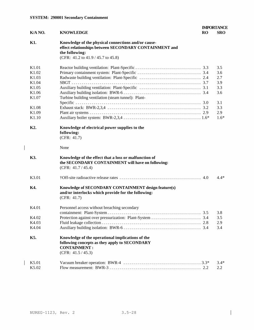
NUREG-1123, Rev. 2 |3.5-28
SYSTEM: 290001 Secondary Containment
IMPORTANCEK/A NO. KNOWLEDGE RO SRO
K1. Knowledge of the physical connections and/or cause-effect relationships between SECONDARY CONTAINMENT andthe following:(CFR: 41.2 to 41.9 / 45.7 to 45.8)
K1.01 Reactor building ventilation: Plant-Specific . . . . . . . . . . . . . . . . . . . . . . . . . . . . . . . . . 3.3 3.5K1.02 Primary containment system: Plant-Specific . . . . . . . . . . . . . . . . . . . . . . . . . . . . . . . . 3.4 3.6K1.03 Radwaste building ventilation: Plant-Specific . . . . . . . . . . . . . . . . . . . . . . . . . . . . . . . 2.4 2.7K1.04 SBGT . . . . . . . . . . . . . . . . . . . . . . . . . . . . . . . . . . . . . . . . . . . . . . . . . . . . . . . . . . . . . . . . . 3.7 3.9K1.05 Auxiliary building ventilation: Plant-Specific . . . . . . . . . . . . . . . . . . . . . . . . . . . . . . . 3.1 3.3K1.06 Auxiliary building isolation: BWR-6 . . . . . . . . . . . . . . . . . . . . . . . . . . . . . . . . . . . . . . . 3.4 3.6K1.07 Turbine building ventilation (steam tunnel): Plant-
Specific . . . . . . . . . . . . . . . . . . . . . . . . . . . . . . . . . . . . . . . . . . . . . . . . . . . . . . . . . . . . . . . 3.0 3.1K1.08 Exhaust stack: BWR-2,3,4 . . . . . . . . . . . . . . . . . . . . . . . . . . . . . . . . . . . . . . . . . . . . . . . 3.2 3.3K1.09 Plant air systems . . . . . . . . . . . . . . . . . . . . . . . . . . . . . . . . . . . . . . . . . . . . . . . . . . . . . . . . 2.9 2.9K1.10 Auxiliary boiler system: BWR-2,3,4 . . . . . . . . . . . . . . . . . . . . . . . . . . . . . . . . . . . . . . . 1.6* 1.6*
K2. Knowledge of electrical power supplies to thefollowing:(CFR: 41.7)
None|
K3. Knowledge of the effect that a loss or malfunction ofthe SECONDARY CONTAINMENT will have on following:(CFR: 41.7 / 45.4)
K3.01 †Off-site radioactive release rates . . . . . . . . . . . . . . . . . . . . . . . . . . . . . . . . . . . . . . . . . 4.0 4.4*
K4. Knowledge of SECONDARY CONTAINMENT design feature(s)and/or interlocks which provide for the following:(CFR: 41.7)
K4.01 Personnel access without breaching secondarycontainment: Plant-System . . . . . . . . . . . . . . . . . . . . . . . . . . . . . . . . . . . . . . . . . . . . . . . 3.5 3.8
K4.02 Protection against over pressurization: Plant-System . . . . . . . . . . . . . . . . . . . . . . . . . 3.4 3.5K4.03 Fluid leakage collection . . . . . . . . . . . . . . . . . . . . . . . . . . . . . . . . . . . . . . . . . . . . . . . . . . 2.8 2.9K4.04 Auxiliary building isolation: BWR-6 . . . . . . . . . . . . . . . . . . . . . . . . . . . . . . . . . . . . . . . 3.4 3.4
K5. Knowledge of the operational implications of thefollowing concepts as they apply to SECONDARYCONTAINMENT :(CFR: 41.5 / 45.3)
K5.01 Vacuum breaker operation: BWR-4 . . . . . . . . . . . . . . . . . . . . . . . . . . . . . . . . . . . . . . . 3.3* 3.4*|K5.02 Flow measurement: BWR-3 . . . . . . . . . . . . . . . . . . . . . . . . . . . . . . . . . . . . . . . . . . . . . . 2.2 2.2
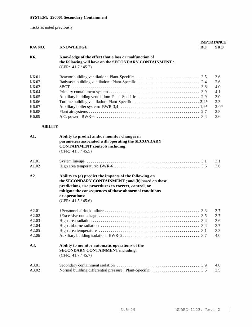
NUREG-1123, Rev. 2 |3.5-29
SYSTEM: 290001 Secondary Containment
Tasks as noted previously
IMPORTANCEK/A NO. KNOWLEDGE RO SRO
K6. Knowledge of the effect that a loss or malfunction ofthe following will have on the SECONDARY CONTAINMENT :(CFR: 41.7 / 45.7)
K6.01 Reactor building ventilation: Plant-Specific . . . . . . . . . . . . . . . . . . . . . . . . . . . . . . . . . 3.5 3.6K6.02 Radwaste building ventilation: Plant-Specific . . . . . . . . . . . . . . . . . . . . . . . . . . . . . . . 2.4 2.6K6.03 SBGT . . . . . . . . . . . . . . . . . . . . . . . . . . . . . . . . . . . . . . . . . . . . . . . . . . . . . . . . . . . . . . . . . 3.8 4.0K6.04 Primary containment system . . . . . . . . . . . . . . . . . . . . . . . . . . . . . . . . . . . . . . . . . . . . . . 3.9 4.1K6.05 Auxiliary building ventilation: Plant-Specific . . . . . . . . . . . . . . . . . . . . . . . . . . . . . . . 2.9 3.0K6.06 Turbine building ventilation: Plant-Specific . . . . . . . . . . . . . . . . . . . . . . . . . . . . . . . . . 2.2* 2.3K6.07 Auxiliary boiler system: BWR-3,4 . . . . . . . . . . . . . . . . . . . . . . . . . . . . . . . . . . . . . . . . 1.9* 2.0*K6.08 Plant air systems . . . . . . . . . . . . . . . . . . . . . . . . . . . . . . . . . . . . . . . . . . . . . . . . . . . . . . . . 2.7 2.8K6.09 A.C. power: BWR-6 . . . . . . . . . . . . . . . . . . . . . . . . . . . . . . . . . . . . . . . . . . . . . . . . . . . . 3.4 3.6
ABILITY
A1. Ability to predict and/or monitor changes inparameters associated with operating the SECONDARYCONTAINMENT controls including:(CFR: 41.5 / 45.5)
A1.01 System lineups . . . . . . . . . . . . . . . . . . . . . . . . . . . . . . . . . . . . . . . . . . . . . . . . . . . . . . . . . 3.1 3.1A1.02 High area temperature: BWR-6 . . . . . . . . . . . . . . . . . . . . . . . . . . . . . . . . . . . . . . . . . . . 3.6 3.6
A2. Ability to (a) predict the impacts of the following onthe SECONDARY CONTAINMENT ; and (b) based on thosepredictions, use procedures to correct, control, ormitigate the consequences of those abnormal conditionsor operations:(CFR: 41.5 / 45.6)
A2.01 †Personnel airlock failure . . . . . . . . . . . . . . . . . . . . . . . . . . . . . . . . . . . . . . . . . . . . . . . . 3.3 3.7A2.02 †Excessive outleakage . . . . . . . . . . . . . . . . . . . . . . . . . . . . . . . . . . . . . . . . . . . . . . . . . . . 3.5 3.7A2.03 High area radiation . . . . . . . . . . . . . . . . . . . . . . . . . . . . . . . . . . . . . . . . . . . . . . . . . . . . . . 3.4 3.6A2.04 High airborne radiation . . . . . . . . . . . . . . . . . . . . . . . . . . . . . . . . . . . . . . . . . . . . . . . . . . 3.4 3.7A2.05 High area temperature . . . . . . . . . . . . . . . . . . . . . . . . . . . . . . . . . . . . . . . . . . . . . . . . . . . 3.1 3.3A2.06 Auxiliary building isolation: BWR-6 . . . . . . . . . . . . . . . . . . . . . . . . . . . . . . . . . . . . . . . 3.7 4.0
A3. Ability to monitor automatic operations of theSECONDARY CONTAINMENT including:(CFR: 41.7 / 45.7)
A3.01 Secondary containment isolation . . . . . . . . . . . . . . . . . . . . . . . . . . . . . . . . . . . . . . . . . . 3.9 4.0A3.02 Normal building differential pressure: Plant-Specific . . . . . . . . . . . . . . . . . . . . . . . . 3.5 3.5

NUREG-1123, Rev. 2 |3.5-30
SYSTEM: 290001 Secondary Containment
Tasks as noted previously
IMPORTANCEK/A NO. ABILITY RO SRO
A4. Ability to manually operate and/or monitor in thecontrol room:(CFR: 41.7 / 45.5 to 45.8)
A4.01 Reactor building differential pressure: Plant-Specific . . . . . . . . . . . . . . . . . . . . . . . . . . . . . . . . . . . . . . . . . . . . . . . . . . . . . . . . . . . . . . . 3.3 3.4
A4.02 Reactor building area temperatures: Plant-Specific . . . . . . . . . . . . . . . . . . . . . . . . . . . 3.3 3.4A4.03 Auxiliary building differential pressure: Plant-
Specific . . . . . . . . . . . . . . . . . . . . . . . . . . . . . . . . . . . . . . . . . . . . . . . . . . . . . . . . . . . . . . . 2.6* 2.7A4.04 Auxiliary building area temperature: Plant-Specific . . . . . . . . . . . . . . . . . . . . . . . . . . . 2.6* 2.7A4.05 Fuel building differential pressure: Plant-Specific . . . . . . . . . . . . . . . . . . . . . . . . . . . . 3.3 3.5A4.06 Fuel building area temperature: Plant-Specific . . . . . . . . . . . . . . . . . . . . . . . . . . . . . . . 3.3 3.5A4.07 Radwaste building differential pressure: Plant-
Specific . . . . . . . . . . . . . . . . . . . . . . . . . . . . . . . . . . . . . . . . . . . . . . . . . . . . . . . . . . . . . . . . 2.3 2.5A4.08 Radwaste building area temperature: Plant-Specific . . . . . . . . . . . . . . . . . . . . . . . . . . . 2.2 2.4A4.09 System status lights and alarms: Plant-Specific . . . . . . . . . . . . . . . . . . . . . . . . . . . . . . . 3.2 3.2A4.10 System lineups: Plant-Specific . . . . . . . . . . . . . . . . . . . . . . . . . . . . . . . . . . . . . . . . . . . . 3.4 3.3A4.11 System reset: Plant-Specific . . . . . . . . . . . . . . . . . . . . . . . . . . . . . . . . . . . . . . . . . . . . . . 3.4 3.4A4.12 Surveillance testing: Plant-Specific . . . . . . . . . . . . . . . . . . . . . . . . . . . . . . . . . . . . . . . . 2.8 3.2
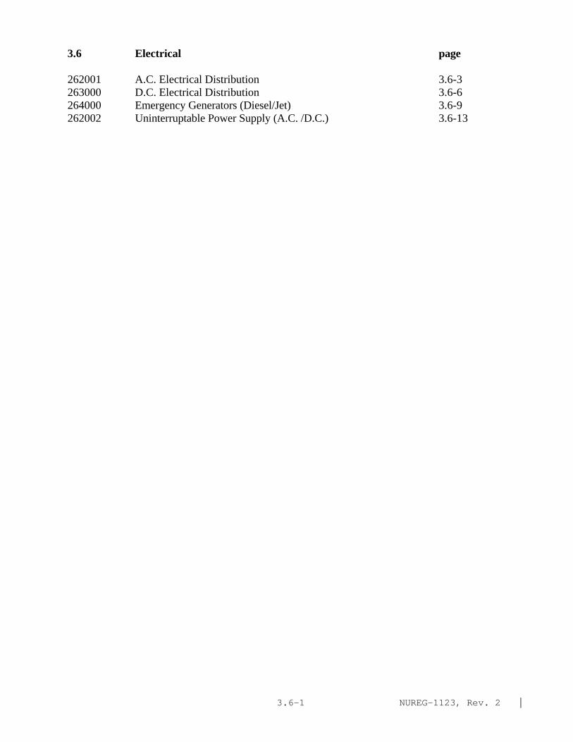
NUREG-1123, Rev. 2 |3.6-1
3.6 Electrical page
262001 A.C. Electrical Distribution 3.6-3263000 D.C. Electrical Distribution 3.6-6264000 Emergency Generators (Diesel/Jet) 3.6-9262002 Uninterruptable Power Supply (A.C. /D.C.) 3.6-13

NUREG-1123, Rev. 2 |3.6-2
This page left blank

NUREG-1123, Rev. 2 |3.6-3
SYSTEM: 226001 A.C. Electrical Distribution
TASK: Lineup the electrical distribution system ( from station power to reserve station power)Shift auxiliary buses between the unit auxiliary XFMR and the service/startup XFMRMonitor the A.C. electrical distribution system (monitor the 416V A.C. power distribution system)Deenergize a motor control center bus from serviceRestore a motor control center bus to serviceDeenergize an engineering safeguards (4160V vital) bus from serviceRestore an engineering safeguards busBackfeed unit auxiliary transformer from main transmission switchyard (main turbine generator linksremoved)Transfer a vital (120V)/instrument bus power supplyOperate a vital motor-generator setPerform ground isolationLineup the electrical distribution system ( from normal power to startup power) (write in)Perform equipment/bus testing for ground faultsPerform operation of circuit breakers and disconnectsPerform emergency A.C. load sequencing and 4KV emergency systems volt relays instrumentationfunction testsPerform circuit or equipment grounding using built-in devices
IMPORTANCE K/A NO. KNOWLEDGE RO SRO
K1. Knowledge of the physical connections and/or cause-effect relationships between A.C. ELECTRICALDISTRIBUTION and the following:(CFR: 41.2 to 41.9 / 45.7 to 45.8)
K1.01 Emergency generators (diesel/jet) . . . . . . . . . . . . . . . . . . . . . . . . . . . . . . . . . . . . . . . . . . 3.8 4.3*K1.02 D.C. electrical distribution . . . . . . . . . . . . . . . . . . . . . . . . . . . . . . . . . . . . . . . . . . . . . . . . 3.3 3.6K1.03 Off-site power sources . . . . . . . . . . . . . . . . . . . . . . . . . . . . . . . . . . . . . . . . . . . . . . . . . . . 3.4 3.8K1.04 Uninterruptible power supply . . . . . . . . . . . . . . . . . . . . . . . . . . . . . . . . . . . . . . . . . . . . . . 3.1 3.4K1.05 Main turbine/generator . . . . . . . . . . . . . . . . . . . . . . . . . . . . . . . . . . . . . . . . . . . . . . . . . . . 3.0 3.2 |K1.06 Alternate shutdown system: Plant-Specific . . . . . . . . . . . . . . . . . . . . . . . . . . . . . . . . . . 3.6 3.9
K2. Knowledge of electrical power supplies to thefollowing:(CFR: 41.7)
K2.01 Off-site sources of power . . . . . . . . . . . . . . . . . . . . . . . . . . . . . . . . . . . . . . . . . . . . . . . . . 3.3 3.6
K3. Knowledge of the effect that a loss or malfunction ofthe A.C. ELECTRICAL DISTRIBUTION will have onfollowing:(CFR: 41.7 / 45.4)
K3.01 Major system loads . . . . . . . . . . . . . . . . . . . . . . . . . . . . . . . . . . . . . . . . . . . . . . . . . . . . . . 3.5 3.7K3.02 Emergency generators . . . . . . . . . . . . . . . . . . . . . . . . . . . . . . . . . . . . . . . . . . . . . . . . . . . . 3.8 4.2

NUREG-1123, Rev. 2 |3.6-4
SYSTEM: 262001 A.C. Electrical Distribution
Tasks as noted previously
IMPORTANCE K/A NO. KNOWLEDGE RO SRO
K3.03 D.C. electrical distribution . . . . . . . . . . . . . . . . . . . . . . . . . . . . . . . . . . . . . . . . . . . . . . . . 2.9 3.2K3.04 Uninterruptible power supply . . . . . . . . . . . . . . . . . . . . . . . . . . . . . . . . . . . . . . . . . . . . . . 3.1 3.3K3.05 Off-site power system . . . . . . . . . . . . . . . . . . . . . . . . . . . . . . . . . . . . . . . . . . . . . . . . . . . . 3.2 3.5K3.06 Reactor protection system . . . . . . . . . . . . . . . . . . . . . . . . . . . . . . . . . . . . . . . . . . . . . . . . 3.8 4.1*
K4. Knowledge of A.C. ELECTRICAL DISTRIBUTION designfeature(s) and/or interlocks which provide for thefollowing:(CFR: 41.7)
K4.01 Bus lockouts . . . . . . . . . . . . . . . . . . . . . . . . . . . . . . . . . . . . . . . . . . . . . . . . . . . . . . . . . . . . 3.0 3.4K4.02 Circuit breaker automatic trips . . . . . . . . . . . . . . . . . . . . . . . . . . . . . . . . . . . . . . . . . . . . . 2.9 3.3K4.03 Interlocks between automatic bus transfer and breakers . . . . . . . . . . . . . . . . . . . . . . . . 3.1 3.4K4.04 Protective relaying . . . . . . . . . . . . . . . . . . . . . . . . . . . . . . . . . . . . . . . . . . . . . . . . . . . . . . . 2.8 3.1K4.05 Paralleling of A.C. sources (synchroscope) . . . . . . . . . . . . . . . . . . . . . . . . . . . . . . . . . . 3.4 3.6K4.06 Redundant power sources to vital buses . . . . . . . . . . . . . . . . . . . . . . . . . . . . . . . . . . . . . . 3.6 3.9
K5. Knowledge of the operational implications of thefollowing concepts as they apply to A.C. ELECTRICALDISTRIBUTION:(CFR: 41.5 / 45.3)
K5.01 Principle involved with paralleling two A.C. sources . . . . . . . . . . . . . . . . . . . . . . . . . . . 3.1 3.4K5.02 Breaker control . . . . . . . . . . . . . . . . . . . . . . . . . . . . . . . . . . . . . . . . . . . . . . . . . . . . . . . . . . 2.6 2.9
K6. Knowledge of the effect that a loss or malfunction ofthe following will have on the A.C. ELECTRICALDISTRIBUTION:(CFR: 41.7 / 45.7)
K6.01 D.C. power . . . . . . . . . . . . . . . . . . . . . . . . . . . . . . . . . . . . . . . . . . . . . . . . . . . . . . . . . . . . . 3.1 3.4K6.02 Off-site power . . . . . . . . . . . . . . . . . . . . . . . . . . . . . . . . . . . . . . . . . . . . . . . . . . . . . . . . . . 3.6 3.9K6.03 Generator trip . . . . . . . . . . . . . . . . . . . . . . . . . . . . . . . . . . . . . . . . . . . . . . . . . . . . . . . . . . . 3.5 3.7
ABILITY
A1. Ability to predict and/or monitor changes in parameters associated with operating the A.C.
ELECTRICAL DISTRIBUTION controls including:(CFR: 41.5 / 45.5)
A1.01 Effect on instrumentation and controls of switchingpower supplies . . . . . . . . . . . . . . . . . . . . . . . . . . . . . . . . . . . . . . . . . . . . . . . . . . . . . . . . . . 3.1 3.4
A1.02 Effects of loads when energizing a bus . . . . . . . . . . . . . . . . . . . . . . . . . . . . . . . . . . . . . . 3.1 3.5A1.03 Bus voltage . . . . . . . . . . . . . . . . . . . . . . . . . . . . . . . . . . . . . . . . . . . . . . . . . . . . . . . . . . . . . 2.9 3.1

NUREG-1123, Rev. 2 |3.6-5
SYSTEM: 262001 A.C. Electrical Distribution
Tasks as noted previously
IMPORTANCE K/A NO. KNOWLEDGE RO SRO
A1.04 Load currents . . . . . . . . . . . . . . . . . . . . . . . . . . . . . . . . . . . . . . . . . . . . . . . . . . . . . . . . . . . 2.7 2.9A1.05 Breaker lineups . . . . . . . . . . . . . . . . . . . . . . . . . . . . . . . . . . . . . . . . . . . . . . . . . . . . . . . . . . 3.2 3.5
A2. Ability to (a) predict the impacts of the following onthe A.C. ELECTRICAL DISTRIBUTION ; and (b) based onthose predictions, use procedures to correct, control,or mitigate the consequences of those abnormalconditions or operations:(CFR: 41.5 / 45.6)
A2.01 Turbine/generator trip . . . . . . . . . . . . . . . . . . . . . . . . . . . . . . . . . . . . . . . . . . . . . . . . . . . . 3.4 3.6A2.02 Loss of coolant accident . . . . . . . . . . . . . . . . . . . . . . . . . . . . . . . . . . . . . . . . . . . . . . . . . . 3.6 3.9A2.03 Loss of off-site power . . . . . . . . . . . . . . . . . . . . . . . . . . . . . . . . . . . . . . . . . . . . . . . . . . . . 3.9 4.3*A2.04 Types of loads that, if deenergized, would degrade or
hinder plant operation . . . . . . . . . . . . . . . . . . . . . . . . . . . . . . . . . . . . . . . . . . . . . . . . . . . . 3.8 4.2A2.05 Bus grounds . . . . . . . . . . . . . . . . . . . . . . . . . . . . . . . . . . . . . . . . . . . . . . . . . . . . . . . . . . . . . 2.9 3.3A2.06 Deenergizing a plant bus . . . . . . . . . . . . . . . . . . . . . . . . . . . . . . . . . . . . . . . . . . . . . . . . . . 2.7 2.9A2.07 Energizing a dead bus . . . . . . . . . . . . . . . . . . . . . . . . . . . . . . . . . . . . . . . . . . . . . . . . . . . . . 3.0 3.2A2.08 Opening a disconnect under load . . . . . . . . . . . . . . . . . . . . . . . . . . . . . . . . . . . . . . . . . . . 3.3 3.6A2.09 Exceeding voltage limitations . . . . . . . . . . . . . . . . . . . . . . . . . . . . . . . . . . . . . . . . . . . . . . 3.1 3.4A2.10 Exceeding current limitations . . . . . . . . . . . . . . . . . . . . . . . . . . . . . . . . . . . . . . . . . . . . . . 2.9 3.4A2.11 Degraded system voltages . . . . . . . . . . . . . . . . . . . . . . . . . . . . . . . . . . . . . . . . . . . . . . . . . 3.2 3.6
A3. Ability to monitor automatic operations of the A.C.ELECTRICAL DISTRIBUTION including:(CFR: 41.7 / 45.7)
A3.01 Breaker tripping . . . . . . . . . . . . . . . . . . . . . . . . . . . . . . . . . . . . . . . . . . . . . . . . . . . . . . . . . 3.1 3.2A3.02 Automatic bus transfer . . . . . . . . . . . . . . . . . . . . . . . . . . . . . . . . . . . . . . . . . . . . . . . . . . . . 3.2 3.3A3.03 Load shedding . . . . . . . . . . . . . . . . . . . . . . . . . . . . . . . . . . . . . . . . . . . . . . . . . . . . . . . . . . . 3.4 3.5A3.04 Load sequencing . . . . . . . . . . . . . . . . . . . . . . . . . . . . . . . . . . . . . . . . . . . . . . . . . . . . . . . . . 3.4 3.6
A4. Ability to manually operate and/or monitor in thecontrol room:(CFR: 41.7 / 45.5 to 45.8)
A4.01 All breakers and disconnects (including availableswitch yard): Plant-Specific . . . . . . . . . . . . . . . . . . . . . . . . . . . . . . . . . . . . . . . . . . . . . . . 3.4 3.7
A4.02 Synchroscope, including understanding of running andincoming voltages . . . . . . . . . . . . . . . . . . . . . . . . . . . . . . . . . . . . . . . . . . . . . . . . . . . . . . . . 3.4 3.4
A4.03 Local operation of breakers . . . . . . . . . . . . . . . . . . . . . . . . . . . . . . . . . . . . . . . . . . . . . . . 3.2 3.4A4.04 Synchronizing and paralleling of different A.C.
supplies . . . . . . . . . . . . . . . . . . . . . . . . . . . . . . . . . . . . . . . . . . . . . . . . . . . . . . . . . . . . . . . . 3.6 3.7A4.05 Voltage, current, power, and frequency on A.C. buses . . . . . . . . . . . . . . . . . . . . . . . . . . 3.3 3.3

NUREG-1123, Rev. 2 |3.6-6
SYSTEM: 263000 D.C. Electrical Distribution
TASK: Startup a battery charger Shift battery chargers Monitor the D.C. electrical distribution system (battery, chargers, distribution and PWR panels) Monitor the D.C. electrical distribution system for grounds Energize D.C. switchboards Deenergize D.C. switchboards Energize D.C. equipment Deenergize D.C. equipment Secure a battery charger
IMPORTANCE K/A NO. KNOWLEDGE RO SRO
K1. Knowledge of the physical connections and/or cause-effect relationships between D.C. ELECTRICALDISTRIBUTION and the following:(CFR: 41.2 to 41.9 / 45.7 to 45.8)
K1.01 A.C. electrical distribution . . . . . . . . . . . . . . . . . . . . . . . . . . . . . . . . . . . . . . . . . . . . . . . 3.3 3.5K1.02 Battery charger and battery . . . . . . . . . . . . . . . . . . . . . . . . . . . . . . . . . . . . . . . . . . . . . . . 3.2 3.3K1.03 Battery ventilation . . . . . . . . . . . . . . . . . . . . . . . . . . . . . . . . . . . . . . . . . . . . . . . . . . . . . . 2.6 2.8K1.04 Ground detection . . . . . . . . . . . . . . . . . . . . . . . . . . . . . . . . . . . . . . . . . . . . . . . . . . . . . . . 2.6 2.9
K2. Knowledge of electrical power supplies to thefollowing:(CFR: 41.7)
K2.01 Major D.C. loads . . . . . . . . . . . . . . . . . . . . . . . . . . . . . . . . . . . . . . . . . . . . . . . . . . . . . . . 3.1 3.4K2.02 Battery room ventilation . . . . . . . . . . . . . . . . . . . . . . . . . . . . . . . . . . . . . . . . . . . . . . . . . 2.1* 2.2*
K3. Knowledge of the effect that a loss or malfunction ofthe D.C. ELECTRICAL DISTRIBUTION will have onfollowing:(CFR: 41.7 / 45.4)
K3.01 Emergency generators: Plant-Specific . . . . . . . . . . . . . . . . . . . . . . . . . . . . . . . . . . . . . 3.4 3.8K3.02 Components using D.C. control power (i.e. breakers) . . . . . . . . . . . . . . . . . . . . . . . . . 3.5 3.8K3.03 Systems with D.C. components (i.e. valves, motors,
solenoids, etc.) . . . . . . . . . . . . . . . . . . . . . . . . . . . . . . . . . . . . . . . . . . . . . . . . . . . . . . . . . 3.4 3.8
K4. Knowledge of D.C. ELECTRICAL DISTRIBUTION designfeature(s) and/or interlocks which provide for thefollowing:(CFR: 41.7)
K4.01 Manual/ automatic transfers of control: Plant-Specific . . . . . . . . . . . . . . . . . . . . . . . . . . . . . . . . . . . . . . . . . . . . . . . . . . . . . . . . . . . . . . . 3.1 3.4
K4.02 Breaker interlocks, permissives, bypasses and crossties: Plant-Specific . . . . . . . . . . . . . . . . . . . . . . . . . . . . . . . . . . . . . . . . . . . . . . . . . . . . . 3.1 3.5

NUREG-1123, Rev. 2 |3.6-7
SYSTEM: 263000 D.C. Electrical Distribution
Tasks as noted previously
IMPORTANCE K/A NO. KNOWLEDGE RO SRO
K5. Knowledge of the operational implications of thefollowing concepts as they apply to D.C. ELECTRICALDISTRIBUTION :(CFR: 41.5 / 45.3)
K5.01 Hydrogen generation during battery charging. . . . . . . . . . . . . . . . . . . . . . . . . . . . . . . . . 2.6 2.9
K6. Knowledge of the effect that a loss or malfunction ofthe following will have on the D.C. ELECTRICALDISTRIBUTION :(CFR: 41.7 / 45.7)
K6.01 A.C. electrical distribution . . . . . . . . . . . . . . . . . . . . . . . . . . . . . . . . . . . . . . . . . . . . . . . . 3.2 3.5K6.02 Battery ventilation . . . . . . . . . . . . . . . . . . . . . . . . . . . . . . . . . . . . . . . . . . . . . . . . . . . . . . . 2.5 2.6
ABILITY
A1. Ability to predict and/or monitor changes inparameters associated with operating the D.C.ELECTRICAL DISTRIBUTION controls including:(CFR: 41.5 / 45.5)
A1.01 Battery charging/discharging rate . . . . . . . . . . . . . . . . . . . . . . . . . . . . . . . . . . . . . . . . . . . 2.5 2.8
A2. Ability to (a) predict the impacts of the following onthe D.C. ELECTRICAL DISTRIBUTION ; and (b) based onthose predictions, use procedures to correct, control,or mitigate the consequences of those abnormalconditions or operations:(CFR: 41.5 / 45.6)
A2.01 Grounds . . . . . . . . . . . . . . . . . . . . . . . . . . . . . . . . . . . . . . . . . . . . . . . . . . . . . . . . . . . . . . . . 2.8 3.2A2.02 Loss of ventilation during charging . . . . . . . . . . . . . . . . . . . . . . . . . . . . . . . . . . . . . . . . . 2.6 2.9
A3. Ability to monitor automatic operations of the D.C.ELECTRICAL DISTRIBUTION including:(CFR: 41.7 / 45.7)
A3.01 Meters, dials, recorders, alarms, and indicatinglights . . . . . . . . . . . . . . . . . . . . . . . . . . . . . . . . . . . . . . . . . . . . . . . . . . . . . . . . . . . . . . . . . . 3.2 3.3
A4. Ability to manually operate and/or monitor in thecontrol room:(CFR: 41.7 / 45.5 to 45.8)
A4.01 Major breakers and control power fuses: Plant-Specific . . . . . . . . . . . . . . . . . . . . . . . . . . . . . . . . . . . . . . . . . . . . . . . . . . . . . . . . . . . . . . . . 3.3 3.5

NUREG-1123, Rev. 2 |3.6-8
SYSTEM: 263000 D.C. Electrical Distribution
Tasks as noted previously
IMPORTANCE K/A NO. KNOWLEDGE RO SRO
A4.02 Battery voltage indicator: Plant-Specific 3.2 3.1A4.03 Battery discharge rate: Plant-Specific 2.7 2.8A4.04 Ground detection circuit: Plant-Specific 3.0 3.2
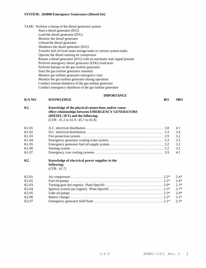
NUREG-1123, Rev. 2 |3.6-9
SYSTEM: 264000 Emergency Generators (Diesel/Jet)
TASK: Perform a lineup of the diesel generator system Start a diesel generator (D/G)Load the diesel generator (D/G) Monitor the diesel generatorUnload the diesel generatorShutdown the diesel generator (D/G)Transfer fuel oil from main storage tanks to various system tanksOperate the diesel starting air compressorRestart a diesel generator (D/G) with an automatic start signal presentPerform emergency diesel generator (EDG) load testsPerform lineups on the gas turbine generatorStart the gas turbine generator remotelyMonitor gas turbine generator emergency startMonitor the gas turbine generator during operationConduct normal shutdown of the gas turbine generatorConduct emergency shutdown of the gas turbine generator
IMPORTANCE K/A NO. KNOWLEDGE RO SRO
K1. Knowledge of the physical connections and/or cause-effect relationships between EMERGENCY GENERATORS(DIESEL/JET) and the following:(CFR: 41.2 to 41.9 / 45.7 to 45.8)
K1.01 A.C. electrical distribution . . . . . . . . . . . . . . . . . . . . . . . . . . . . . . . . . . . . . . . . . . . . . . . 3.8 4.1K1.02 D.C. electrical distribution . . . . . . . . . . . . . . . . . . . . . . . . . . . . . . . . . . . . . . . . . . . . . . . 3.3 3.4K1.03 Fire protection system . . . . . . . . . . . . . . . . . . . . . . . . . . . . . . . . . . . . . . . . . . . . . . . . . . . 2.9 3.2K1.04 Emergency generator cooling water system . . . . . . . . . . . . . . . . . . . . . . . . . . . . . . . . . 3.2 3.3K1.05 Emergency generator fuel oil supply system . . . . . . . . . . . . . . . . . . . . . . . . . . . . . . . . . 3.2 3.3K1.06 Starting system . . . . . . . . . . . . . . . . . . . . . . . . . . . . . . . . . . . . . . . . . . . . . . . . . . . . . . . . . 3.2 3.2K1.07 Emergency core cooling systems . . . . . . . . . . . . . . . . . . . . . . . . . . . . . . . . . . . . . . . . . . 3.9 4.1
K2. Knowledge of electrical power supplies to thefollowing:(CFR: 41.7)
K2.01 Air compressor . . . . . . . . . . . . . . . . . . . . . . . . . . . . . . . . . . . . . . . . . . . . . . . . . . . . . . . . . 2.2* 2.4*K2.02 Fuel oil pumps . . . . . . . . . . . . . . . . . . . . . . . . . . . . . . . . . . . . . . . . . . . . . . . . . . . . . . . . . 2.2* 2.4*K2.03 Turning gear (jet engine): Plant-Specific . . . . . . . . . . . . . . . . . . . . . . . . . . . . . . . . . . . 2.0* 2.3*K2.04 Ignition system (jet engine): Plant-Specific . . . . . . . . . . . . . . . . . . . . . . . . . . . . . . . . . 2.3* 2.7*K2.05 Lube oil pumps . . . . . . . . . . . . . . . . . . . . . . . . . . . . . . . . . . . . . . . . . . . . . . . . . . . . . . . . . 2.3* 2.4*K2.06 Battery charger . . . . . . . . . . . . . . . . . . . . . . . . . . . . . . . . . . . . . . . . . . . . . . . . . . . . . . . . . 2.2* 2.2*K2.07 Emergency generator field flash . . . . . . . . . . . . . . . . . . . . . . . . . . . . . . . . . . . . . . . . . . . 2.1* 2.3*
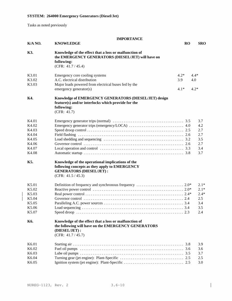
NUREG-1123, Rev. 2 |3.6-10
SYSTEM: 264000 Emergency Generators (Diesel/Jet)
Tasks as noted previously
IMPORTANCE K/A NO. KNOWLEDGE RO SRO
K3. Knowledge of the effect that a loss or malfunction ofthe EMERGENCY GENERATORS (DIESEL/JET) will have onfollowing:(CFR: 41.7 / 45.4)
K3.01 Emergency core cooling systems 4.2* 4.4*K3.02 A.C. electrical distribution 3.9 4.0K3.03 Major loads powered from electrical buses fed by the
emergency generator(s) 4.1* 4.2*
K4. Knowledge of EMERGENCY GENERATORS (DIESEL/JET) designfeature(s) and/or interlocks which provide for thefollowing:(CFR: 41.7)
K4.01 Emergency generator trips (normal) . . . . . . . . . . . . . . . . . . . . . . . . . . . . . . . . . . . . . . . 3.5 3.7K4.02 Emergency generator trips (emergency/LOCA) . . . . . . . . . . . . . . . . . . . . . . . . . . . . . . 4.0 4.2K4.03 Speed droop control . . . . . . . . . . . . . . . . . . . . . . . . . . . . . . . . . . . . . . . . . . . . . . . . . . . . . 2.5 2.7K4.04 Field flashing . . . . . . . . . . . . . . . . . . . . . . . . . . . . . . . . . . . . . . . . . . . . . . . . . . . . . . . . . . 2.6 2.7K4.05 Load shedding and sequencing . . . . . . . . . . . . . . . . . . . . . . . . . . . . . . . . . . . . . . . . . . . . 3.2 3.5K4.06 Governor control . . . . . . . . . . . . . . . . . . . . . . . . . . . . . . . . . . . . . . . . . . . . . . . . . . . . . . . 2.6 2.7K4.07 Local operation and control . . . . . . . . . . . . . . . . . . . . . . . . . . . . . . . . . . . . . . . . . . . . . . 3.3 3.4K4.08 Automatic startup . . . . . . . . . . . . . . . . . . . . . . . . . . . . . . . . . . . . . . . . . . . . . . . . . . . . . . . 3.8 3.7
K5. Knowledge of the operational implications of thefollowing concepts as they apply to EMERGENCYGENERATORS (DIESEL/JET) :(CFR: 41.5 / 45.3)
K5.01 Definition of frequency and synchronous frequency . . . . . . . . . . . . . . . . . . . . . . . . . . 2.0* 2.1*K5.02 Reactive power control . . . . . . . . . . . . . . . . . . . . . . . . . . . . . . . . . . . . . . . . . . . . . . . . . . 2.0* 2.1*K5.03 Real power control . . . . . . . . . . . . . . . . . . . . . . . . . . . . . . . . . . . . . . . . . . . . . . . . . . . . . . 2.4* 2.4*|K5.04 Governor control . . . . . . . . . . . . . . . . . . . . . . . . . . . . . . . . . . . . . . . . . . . . . . . . . . . . . . . 2.4 2.5|K5.05 Paralleling A.C. power sources . . . . . . . . . . . . . . . . . . . . . . . . . . . . . . . . . . . . . . . . . . . . 3.4 3.4K5.06 Load sequencing . . . . . . . . . . . . . . . . . . . . . . . . . . . . . . . . . . . . . . . . . . . . . . . . . . . . . . . . 3.4 3.5K5.07 Speed droop . . . . . . . . . . . . . . . . . . . . . . . . . . . . . . . . . . . . . . . . . . . . . . . . . . . . . . . . . . . 2.3 2.4
K6. Knowledge of the effect that a loss or malfunction ofthe following will have on the EMERGENCY GENERATORS(DIESEL/JET) :(CFR: 41.7 / 45.7)
K6.01 Starting air . . . . . . . . . . . . . . . . . . . . . . . . . . . . . . . . . . . . . . . . . . . . . . . . . . . . . . . . . . . . . 3.8 3.9K6.02 Fuel oil pumps . . . . . . . . . . . . . . . . . . . . . . . . . . . . . . . . . . . . . . . . . . . . . . . . . . . . . . . . . 3.6 3.6K6.03 Lube oil pumps . . . . . . . . . . . . . . . . . . . . . . . . . . . . . . . . . . . . . . . . . . . . . . . . . . . . . . . . . 3.5 3.7K6.04 Turning gear (jet engine): Plant-Specific . . . . . . . . . . . . . . . . . . . . . . . . . . . . . . . . . . . 2.5 2.5K6.05 Ignition system (jet engine): Plant-Specific . . . . . . . . . . . . . . . . . . . . . . . . . . . . . . . . . 2.5 3.0
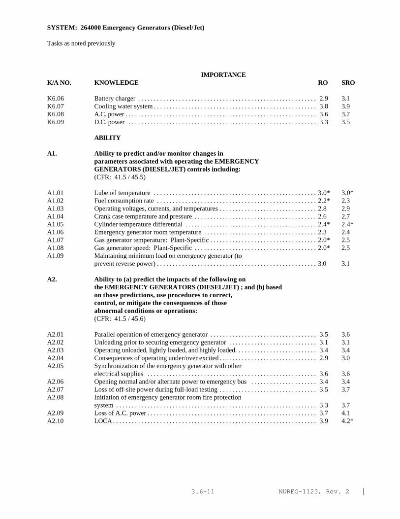
NUREG-1123, Rev. 2 |3.6-11
SYSTEM: 264000 Emergency Generators (Diesel/Jet)
Tasks as noted previously
IMPORTANCE K/A NO. KNOWLEDGE RO SRO
K6.06 Battery charger . . . . . . . . . . . . . . . . . . . . . . . . . . . . . . . . . . . . . . . . . . . . . . . . . . . . . . . . . 2.9 3.1K6.07 Cooling water system . . . . . . . . . . . . . . . . . . . . . . . . . . . . . . . . . . . . . . . . . . . . . . . . . . . . 3.8 3.9K6.08 A.C. power . . . . . . . . . . . . . . . . . . . . . . . . . . . . . . . . . . . . . . . . . . . . . . . . . . . . . . . . . . . . . 3.6 3.7K6.09 D.C. power . . . . . . . . . . . . . . . . . . . . . . . . . . . . . . . . . . . . . . . . . . . . . . . . . . . . . . . . . . . . 3.3 3.5
ABILITY
A1. Ability to predict and/or monitor changes inparameters associated with operating the EMERGENCYGENERATORS (DIESEL/JET) controls including:(CFR: 41.5 / 45.5)
A1.01 Lube oil temperature . . . . . . . . . . . . . . . . . . . . . . . . . . . . . . . . . . . . . . . . . . . . . . . . . . . . 3.0* 3.0*A1.02 Fuel consumption rate . . . . . . . . . . . . . . . . . . . . . . . . . . . . . . . . . . . . . . . . . . . . . . . . . . . 2.2* 2.3A1.03 Operating voltages, currents, and temperatures . . . . . . . . . . . . . . . . . . . . . . . . . . . . . . . 2.8 2.9A1.04 Crank case temperature and pressure . . . . . . . . . . . . . . . . . . . . . . . . . . . . . . . . . . . . . . . 2.6 2.7A1.05 Cylinder temperature differential . . . . . . . . . . . . . . . . . . . . . . . . . . . . . . . . . . . . . . . . . . 2.4* 2.4*A1.06 Emergency generator room temperature . . . . . . . . . . . . . . . . . . . . . . . . . . . . . . . . . . . . 2.3 2.4A1.07 Gas generator temperature: Plant-Specific . . . . . . . . . . . . . . . . . . . . . . . . . . . . . . . . . . 2.0* 2.5A1.08 Gas generator speed: Plant-Specific . . . . . . . . . . . . . . . . . . . . . . . . . . . . . . . . . . . . . . . 2.0* 2.5A1.09 Maintaining minimum load on emergency generator (to
prevent reverse power) . . . . . . . . . . . . . . . . . . . . . . . . . . . . . . . . . . . . . . . . . . . . . . . . . . . 3.0 3.1
A2. Ability to (a) predict the impacts of the following onthe EMERGENCY GENERATORS (DIESEL/JET) ; and (b) basedon those predictions, use procedures to correct,control, or mitigate the consequences of thoseabnormal conditions or operations:(CFR: 41.5 / 45.6)
A2.01 Parallel operation of emergency generator . . . . . . . . . . . . . . . . . . . . . . . . . . . . . . . . . . 3.5 3.6A2.02 Unloading prior to securing emergency generator . . . . . . . . . . . . . . . . . . . . . . . . . . . . 3.1 3.1A2.03 Operating unloaded, lightly loaded, and highly loaded. . . . . . . . . . . . . . . . . . . . . . . . . . 3.4 3.4A2.04 Consequences of operating under/over excited . . . . . . . . . . . . . . . . . . . . . . . . . . . . . . . 2.9 3.0A2.05 Synchronization of the emergency generator with other
electrical supplies . . . . . . . . . . . . . . . . . . . . . . . . . . . . . . . . . . . . . . . . . . . . . . . . . . . . . . 3.6 3.6A2.06 Opening normal and/or alternate power to emergency bus . . . . . . . . . . . . . . . . . . . . . 3.4 3.4A2.07 Loss of off-site power during full-load testing . . . . . . . . . . . . . . . . . . . . . . . . . . . . . . . 3.5 3.7A2.08 Initiation of emergency generator room fire protection
system . . . . . . . . . . . . . . . . . . . . . . . . . . . . . . . . . . . . . . . . . . . . . . . . . . . . . . . . . . . . . . . . 3.3 3.7A2.09 Loss of A.C. power . . . . . . . . . . . . . . . . . . . . . . . . . . . . . . . . . . . . . . . . . . . . . . . . . . . . . . 3.7 4.1A2.10 LOCA . . . . . . . . . . . . . . . . . . . . . . . . . . . . . . . . . . . . . . . . . . . . . . . . . . . . . . . . . . . . . . . . . 3.9 4.2*

NUREG-1123, Rev. 2 |3.6-12
SYSTEM: 264000 Emergency Generators (Diesel/Jet)
Tasks as noted previously
IMPORTANCE K/A NO. KNOWLEDGE RO SRO
A3. Ability to monitor automatic operations of theEMERGENCY GENERATORS (DIESEL/JET) including:(CFR: 41.7 / 45.7)
A3.01 Automatic starting of compressor and emergencygenerator . . . . . . . . . . . . . . . . . . . . . . . . . . . . . . . . . . . . . . . . . . . . . . . . . . . . . . . . . . . . . . 3.0 3.1
A3.02 Minimum time for load pick up . . . . . . . . . . . . . . . . . . . . . . . . . . . . . . . . . . . . . . . . . . . 3.1 3.1A3.03 Indicating lights, meters, and recorders . . . . . . . . . . . . . . . . . . . . . . . . . . . . . . . . . . . . . 3.4 3.4A3.04 Operation of the governor control system on frequency
and voltage control . . . . . . . . . . . . . . . . . . . . . . . . . . . . . . . . . . . . . . . . . . . . . . . . . . . . . . 3.1 3.1A3.05 Load shedding and sequencing . . . . . . . . . . . . . . . . . . . . . . . . . . . . . . . . . . . . . . . . . . . . 3.4 3.5A3.06 Cooling water system operation . . . . . . . . . . . . . . . . . . . . . . . . . . . . . . . . . . . . . . . . . . . 3.1 3.2
A4. Ability to manually operate and/or monitor in thecontrol room:(CFR: 41.7 / 45.5 to 45.8)
A4.01 Adjustment of exciter voltage . . . . . . . . . . . . . . . . . . . . . . . . . . . . . . . . . . . . . . . . . . . . . 3.3 3.4A4.02 Synchroscope . . . . . . . . . . . . . . . . . . . . . . . . . . . . . . . . . . . . . . . . . . . . . . . . . . . . . . . . . . 3.4 3.4A4.03 Transfer of emergency control between manual and
automatic . . . . . . . . . . . . . . . . . . . . . . . . . . . . . . . . . . . . . . . . . . . . . . . . . . . . . . . . . . . . . . 3.2 3.4A4.04 Manual start, loading, and stopping of emergency
generator: Plant-Specific . . . . . . . . . . . . . . . . . . . . . . . . . . . . . . . . . . . . . . . . . . . . . . . . 3.7 3.7A4.05 Transfer of emergency generator (with load) to grid . . . . . . . . . . . . . . . . . . . . . . . . . . 3.6 3.7A4.06 Droop setting . . . . . . . . . . . . . . . . . . . . . . . . . . . . . . . . . . . . . . . . . . . . . . . . . . . . . . . . . . 2.4* 2.8*

NUREG-1123, Rev. 2 |3.6-13
SYSTEM: 262002 Uninterruptable Power Supply (A.C./D.C.)
TASK: Operate a static inverter
IMPORTANCE K/A NO. KNOWLEDGE RO SRO
K1. Knowledge of the physical connections and/or cause-effect relationships between UNINTERRUPTABLE POWERSUPPLY (A.C./D.C.) and the following:(CFR: 41.2 to 41.9 / 45.7 to 45.8)
K1.01 Feedwater level control: Plant-Specific . . . . . . . . . . . . . . . . . . . . . . . . . . . . . . . . . . . . 2.8 3.0K1.02 RFPT control: Plant-Specific . . . . . . . . . . . . . . . . . . . . . . . . . . . . . . . . . . . . . . . . . . . . . 2.8 3.0K1.03 Rod position information: Plant-Specific . . . . . . . . . . . . . . . . . . . . . . . . . . . . . . . . . . . 2.7 2.9K1.04 Reactor manual control: Plant-Specific . . . . . . . . . . . . . . . . . . . . . . . . . . . . . . . . . . . . 2.8 3.0K1.05 Reactor/turbine pressure control system control unit:
Plant-Specific . . . . . . . . . . . . . . . . . . . . . . . . . . . . . . . . . . . . . . . . . . . . . . . . . . . . . . . . . . 2.7 2.9K1.06 Unit computer: Plant-Specific . . . . . . . . . . . . . . . . . . . . . . . . . . . . . . . . . . . . . . . . . . . . 2.6 2.7K1.07 Rod worth minimizer: Plant-Specific . . . . . . . . . . . . . . . . . . . . . . . . . . . . . . . . . . . . . . 2.8 2.9K1.08 Containment isolation system: Plant-Specific . . . . . . . . . . . . . . . . . . . . . . . . . . . . . . . 2.9 3.1K1.09 Drywell ventilation control: Plant-Specific . . . . . . . . . . . . . . . . . . . . . . . . . . . . . . . . . 2.5 2.7K1.10 Fire protection system: Plant-Specific . . . . . . . . . . . . . . . . . . . . . . . . . . . . . . . . . . . . . 2.6 2.8K1.11 Control room recorders: Plant-Specific . . . . . . . . . . . . . . . . . . . . . . . . . . . . . . . . . . . . 2.5 2.6K1.12 Generator hydrogen and stator cooling water controls:
Plant-Specific . . . . . . . . . . . . . . . . . . . . . . . . . . . . . . . . . . . . . . . . . . . . . . . . . . . . . . . . . . 2.1* 2.3*K1.13 Recirculation pump speed control: Plant-Specific . . . . . . . . . . . . . . . . . . . . . . . . . . . 2.5 2.6K1.14 Main steam line radiation monitors: Plant-Specific . . . . . . . . . . . . . . . . . . . . . . . . . . 2.8 3.0K1.15 Stack gas monitors: Plant-Specific . . . . . . . . . . . . . . . . . . . . . . . . . . . . . . . . . . . . . . . . 2.7 3.0K1.16 MSIV's: Plant-Specific . . . . . . . . . . . . . . . . . . . . . . . . . . . . . . . . . . . . . . . . . . . . . . . . . . 3.1 3.2K1.17 Scram solenoid valves: Plant-Specific . . . . . . . . . . . . . . . . . . . . . . . . . . . . . . . . . . . . . 3.1 3.3K1.18 Process radiation monitoring system: Plant-Specific . . . . . . . . . . . . . . . . . . . . . . . . . 2.5 2.7K1.19 Power range neutron monitoring system: Plant-Specific . . . . . . . . . . . . . . . . . . . . . . 2.9* 3.1*K1.20 Plant communications equipment: Plant-Specific . . . . . . . . . . . . . . . . . . . . . . . . . . . . 2.4 2.7
K2. Knowledge of electrical power supplies to thefollowing:(CFR: 41.7)
None |
K3. Knowledge of the effect that a loss or malfunction ofthe UNINTERRUPTABLE POWER SUPPLY (A.C./D.C.) will haveon following:(CFR: 41.7 / 45.4)
K3.01 Water level control: Plant-Specific . . . . . . . . . . . . . . . . . . . . . . . . . . . . . . . . . . . . . . . . 3.1 3.3K3.02 Recirculation pump speed: Plant-Specific . . . . . . . . . . . . . . . . . . . . . . . . . . . . . . . . . . 2.9 2.9K3.03 RFPT speed: Plant-Specific . . . . . . . . . . . . . . . . . . . . . . . . . . . . . . . . . . . . . . . . . . . . . . 3.0 3.1K3.04 Fire protection system: Plant-Specific . . . . . . . . . . . . . . . . . . . . . . . . . . . . . . . . . . . . 2.5 2.7K3.05 Rod worth minimizer: Plant-Specific . . . . . . . . . . . . . . . . . . . . . . . . . . . . . . . . . . . . . . 2.9 3.0K3.06 Rod position indication: Plant-Specific . . . . . . . . . . . . . . . . . . . . . . . . . . . . . . . . . . . . 2.8 2.9K3.07 Movement of control rods: Plant-Specific . . . . . . . . . . . . . . . . . . . . . . . . . . . . . . . . . . 2.6 2.8K3.08 Computer operation: Plant-Specific . . . . . . . . . . . . . . . . . . . . . . . . . . . . . . . . . . . . . . . 2.7 2.8

NUREG-1123, Rev. 2 |3.6-14
SYSTEM: 262002 Uninterruptable Power Supply (A.C./D.C.)
Tasks as noted previously
IMPORTANCE K/A NO. KNOWLEDGE RO SRO
K3.09 Drywell ventilation control: Plant-Specific . . . . . . . . . . . . . . . . . . . . . . . . . . . . . . . . . 2.4 2.7K3.10 Containment isolation: Plant-Specific . . . . . . . . . . . . . . . . . . . . . . . . . . . . . . . . . . . . . 2.7 2.8K3.11 MSIV's: Plant-Specific . . . . . . . . . . . . . . . . . . . . . . . . . . . . . . . . . . . . . . . . . . . . . . . . . . 2.8 2.9K3.12 Control rod drive mechanism: Plant-Specific . . . . . . . . . . . . . . . . . . . . . . . . . . . . . . . 2.3* 2.5K3.13 Rx pressure: Plant-Specific . . . . . . . . . . . . . . . . . . . . . . . . . . . . . . . . . . . . . . . . . . . . . . 2.7 2.9K3.14 Rx power: Plant-Specific . . . . . . . . . . . . . . . . . . . . . . . . . . . . . . . . . . . . . . . . . . . . . . . . 2.8 3.1K3.15 Main turbine operation: Plant-Specific . . . . . . . . . . . . . . . . . . . . . . . . . . . . . . . . . . . . . 2.6 2.7K3.16 Control room recorders: Plant-Specific . . . . . . . . . . . . . . . . . . . . . . . . . . . . . . . . . . . . 2.4 2.6K3.17 Process monitoring: Plant-Specific . . . . . . . . . . . . . . . . . . . . . . . . . . . . . . . . . . . . . . . 2.9 3.1
K4. Knowledge of UNINTERRUPTABLE POWER SUPPLY (A.C./D.C.)design feature(s) and/or interlocks which provide forthe following:(CFR: 41.7)
K4.01 Transfer from preferred power to alternate powersupplies . . . . . . . . . . . . . . . . . . . . . . . . . . . . . . . . . . . . . . . . . . . . . . . . . . . . . . . . . . . . . . . 3.1 3.4
K5. Knowledge of the operational implications of thefollowing concepts as they apply to UNINTERRUPTABLEPOWER SUPPLY (A.C./D.C.) :(CFR: 41.5 / 45.3)
K5.01 General principles of static inverter operation . . . . . . . . . . . . . . . . . . . . . . . . . . . . . . . 2.3* 2.3K5.02 General principles of motor generator operation:
Plant-Specific . . . . . . . . . . . . . . . . . . . . . . . . . . . . . . . . . . . . . . . . . . . . . . . . . . . . . . . . . . 2.4 2.5K5.03 General principles of inertia fly wheel operation:
Plant-Specific . . . . . . . . . . . . . . . . . . . . . . . . . . . . . . . . . . . . . . . . . . . . . . . . . . . . . . . . . . 2.3* 2.4*K5.04 General principles of static switch operation . . . . . . . . . . . . . . . . . . . . . . . . . . . . . . . . 2.1* 2.2*
K6. Knowledge of the effect that a loss or malfunction ofthe following will have on the UNINTERRUPTABLE POWERSUPPLY (A.C./D.C.) :(CFR: 41.7 / 45.7)
K6.01 A.C. electrical power . . . . . . . . . . . . . . . . . . . . . . . . . . . . . . . . . . . . . . . . . . . . . . . . . . . . 2.7 2.9K6.02 D.C. electrical power . . . . . . . . . . . . . . . . . . . . . . . . . . . . . . . . . . . . . . . . . . . . . . . . . . . . 2.8 3.1K6.03 Static inverter . . . . . . . . . . . . . . . . . . . . . . . . . . . . . . . . . . . . . . . . . . . . . . . . . . . . . . . . . . 2.7 2.9

NUREG-1123, Rev. 2 |3.6-15
SYSTEM: 262002 Uninterruptable Power Supply (A.C./D.C.)
Tasks as noted previously
IMPORTANCE K/A NO. ABILITY RO SRO
A1. Ability to predict and/or monitor changes inparameters associated with operating theUNINTERRUPTABLE POWER SUPPLY (A.C./D.C.) controlsincluding:(CFR: 41.5 / 45.5)
A1.01 Inverter electrical outputs . . . . . . . . . . . . . . . . . . . . . . . . . . . . . . . . . . . . . . . . . . . . . . . . 2.4 2.6A1.02 Motor generator outputs . . . . . . . . . . . . . . . . . . . . . . . . . . . . . . . . . . . . . . . . . . . . . . . . . 2.5 2.9
A2. Ability to (a) predict the impacts of the following onthe UNINTERRUPTABLE POWER SUPPLY (A.C./D.C.) ; and (b)based on those predictions, use procedures to correct,control, or mitigate the consequences of thoseabnormal conditions or operations:(CFR: 41.5 / 45.6)
A2.01 Under voltage . . . . . . . . . . . . . . . . . . . . . . . . . . . . . . . . . . . . . . . . . . . . . . . . . . . . . . . . . . 2.6 2.8A2.02 Over voltage . . . . . . . . . . . . . . . . . . . . . . . . . . . . . . . . . . . . . . . . . . . . . . . . . . . . . . . . . . . 2.5 2.7A2.03 Frequency changes in the system . . . . . . . . . . . . . . . . . . . . . . . . . . . . . . . . . . . . . . . . . . 2.4* 2.6A2.04 Abnormal battery operation: BWR-1 . . . . . . . . . . . . . . . . . . . . . . . . . . . . . . . . . . . . . . 3.2 3.4
A3. Ability to monitor automatic operations of theUNINTERRUPTABLE POWER SUPPLY (A.C./D.C.) including:(CFR: 41.7 / 45.7)
A3.01 Transfer from preferred to alternate source . . . . . . . . . . . . . . . . . . . . . . . . . . . . . . . . . 2.8 3.1
A4. Ability to manually operate and/or monitor in thecontrol room:(CFR: 41.7 / 45.5 to 45.8)
A4.01 Transfer from alternative source to preferred source . . . . . . . . . . . . . . . . . . . . . . . . . . 2.8 3.1

NUREG-1123, Rev. 2 |3.7-1
3.7 Instrumentation page
215005 Average Power Range Monitor/Local Power Range Monitor 3.7-3215003 Intermediate Range Monitor System 3.7-7216000 Nuclear Boiler Instrumentation 3.7-10272000 Radiation Monitoring System 3.7-15212000 Reactor Protection System 3.7-19215002 Rod Block Monitor System 3.7-24201005 Rod Control and Information System 3.7-27214000 Rod Position Information System 3.7-30201004 Rod Sequence Control System (Plant Specific) 3.7-33201006 Rod Worth Minimizer System (Plant Specific) 3.7-35215004 Source Range Monitor System 3.7-38215001 Traversing In-Core Probe 3.7-41

NUREG-1123, Rev. 2 |3.7-2
This page left blank

NUREG-1123, Rev. 2 |3.7-3
SYSTEM: 215005 Average Power Range Monitor/Local Power Range Monitor System
TASK: Perform lineups of the nuclear instrumentation system Monitor the nuclear instrumentation system Startup the nuclear instrumentation system Place a source range module in/out of service Place power range instruments in/out of service Operate the nuclear instrumentation systemSecure the nuclear instrumentation systemPlace transversing incore probe in/out of serviceOperate range switches on IRM on power increase and decrease (write in)Conduct average power range meter (APRM) instrument functional testConduct intermediate range monitor - average power range monitor instrument range overlap checkConduct IRM-inoperative functional test and IRM-high flux functional instrument checkConduct APRM-high flux in start up or refuel functional test
IMPORTANCE K/A NO. KNOWLEDGE RO SRO
K1. Knowledge of the physical connections and/or cause-effect relationships between AVERAGE POWER RANGEMONITOR/LOCAL POWER RANGE MONITOR SYSTEM and thefollowing:(CFR: 41.2 to 41.9 / 45.7 to 45.8)
K1.01 RPS . . . . . . . . . . . . . . . . . . . . . . . . . . . . . . . . . . . . . . . . . . . . . . . . . . . . . . . . . . . . . . . . . . . 4.0 4.0K1.02 IRM . . . . . . . . . . . . . . . . . . . . . . . . . . . . . . . . . . . . . . . . . . . . . . . . . . . . . . . . . . . . . . . . . . . 3.7 3.7K1.03 RBM: Plant-Specific . . . . . . . . . . . . . . . . . . . . . . . . . . . . . . . . . . . . . . . . . . . . . . . . . . . . . 3.4 3.5K1.04 LPRM channels . . . . . . . . . . . . . . . . . . . . . . . . . . . . . . . . . . . . . . . . . . . . . . . . . . . . . . . . . 3.6 3.6K1.05 Four rod display: Plant-Specific . . . . . . . . . . . . . . . . . . . . . . . . . . . . . . . . . . . . . . . . . . . 3.2 3.2K1.06 SPDS/ERIS/CRIDS/GDS: Plant-Specific . . . . . . . . . . . . . . . . . . . . . . . . . . . . . . . . . . . . 2.5 2.8*K1.07 Process computer, performance monitoring system . . . . . . . . . . . . . . . . . . . . . . . . . . . 2.6 2.9K1.08 Display control system: Plant-Specific . . . . . . . . . . . . . . . . . . . . . . . . . . . . . . . . . . . . . 3.0 3.0K1.09 Reactor recirculation system: BWR-5,6 . . . . . . . . . . . . . . . . . . . . . . . . . . . . . . . . . . . . 3.6 3.6K1.10 Reactor manual control system: Plant-Specific . . . . . . . . . . . . . . . . . . . . . . . . . . . . . . . 3.3 3.3K1.11 Rod control and information system: Plant-Specific . . . . . . . . . . . . . . . . . . . . . . . . . . 3.4 3.4K1.12 Full core display . . . . . . . . . . . . . . . . . . . . . . . . . . . . . . . . . . . . . . . . . . . . . . . . . . . . . . . . . 3.2 3.2K1.13 Traversing incore probe system . . . . . . . . . . . . . . . . . . . . . . . . . . . . . . . . . . . . . . . . . . . . 2.6 3.0K1.14 Reactor vessel . . . . . . . . . . . . . . . . . . . . . . . . . . . . . . . . . . . . . . . . . . . . . . . . . . . . . . . . . . . 2.8 2.9K1.15 Redundant reactivity control system: Plant-Specific . . . . . . . . . . . . . . . . . . . . . . . . . . . 3.7 4.0K1.16 Flow converter/comparator network: Plant-Specific . . . . . . . . . . . . . . . . . . . . . . . . . . . 3.3 3.4
K2. Knowledge of electrical power supplies to thefollowing:(CFR: 41.7)
K2.01 LPRM channels . . . . . . . . . . . . . . . . . . . . . . . . . . . . . . . . . . . . . . . . . . . . . . . . . . . . . . . . . 2.4 2.6K2 02 APRM channels . . . . . . . . . . . . . . . . . . . . . . . . . . . . . . . . . . . . . . . . . . . . . . . . . . . . . . . . . 2.6 2.8

NUREG-1123, Rev. 2 |3.7-4
SYSTEM: 215005 Average Power Range Monitor/Local Power Range Monitor System
Tasks as noted previously
IMPORTANCE K/A NO. KNOWLEDGE RO SRO
K3. Knowledge of the effect that a loss or malfunction ofthe AVERAGE POWER RANGE MONITOR/LOCAL POWER RANGEMONITOR SYSTEM will have on following:(CFR: 41.7 / 45.4)
K3.01 RPS . . . . . . . . . . . . . . . . . . . . . . . . . . . . . . . . . . . . . . . . . . . . . . . . . . . . . . . . . . . . . . . 4.0 4.0K3.02 Reactor recirculation system: BWR-5,6 . . . . . . . . . . . . . . . . . . . . . . . . . . . . . . . . 3.5 3.5K3.03 Reactor manual control system: Plant-Specific . . . . . . . . . . . . . . . . . . . . . . . . . . . 3.3 3.3K3.04 Rod control and information system: Plant-Specific 3.4 . . . . . . . . . . . . . . . . . 3.4K3.05 Reactor power indication . . . . . . . . . . . . . . . . . . . . . . . . . . . . . . . . . . . . . . . . . . . . . . 3.8 3.8K3.06 IRM: Plant-Specific . . . . . . . . . . . . . . . . . . . . . . . . . . . . . . . . . . . . . . . . . . . . . . . . . 3.5 3.6K3.07 Rod block monitor: Plant-Specific . . . . . . . . . . . . . . . . . . . . . . . . . . . . . . . . . . . . . 3.2 3.3K3.08 †core thermal calculations . . . . . . . . . . . . . . . . . . . . . . . . . . . . . . . . . . . . . . . . . . . . 3.0 3.4
K4. Knowledge of AVERAGE POWER RANGE MONITOR/LOCAL POWERRANGE MONITOR SYSTEM design feature(s) and/orinterlocks which provide for the following:(CFR: 41.7)
K4.01 Rod withdrawal blocks . . . . . . . . . . . . . . . . . . . . . . . . . . . . . . . . . . . . . . . . . . . . . . . 3.7 3.7K4.02 Reactor SCRAM signals 4.1* 4.2K4.03 Eliminates the necessity of running signal leads from
each LPRM channel to the operator's console full coredisplay 2.1?* 2.2?*
K4.04 Individual LPRM detector replacement 2.0* 2.4*K4.05 Alarm seal-in 2.4 2.4K4.06 Effects of detector aging on LPRM/APRM readings 2.6 2.8K4.07 Flow biased trip setpoints 3.7 3.7K4.08 Sampling of overall core power in each APRM
(accomplished through LPRM assignments and symmetricalrod patterns) 2.7 3.1
K5. Knowledge of the operational implications of thefollowing concepts as they apply to AVERAGE POWERRANGE MONITOR/LOCAL POWER RANGE MONITOR SYSTEM :(CFR: 41.5 / 45.3)
K5.01 LPRM detector operation 2.8 2.9K5.02 Effects of voids on LPRM indication 2.7 2.8K5.03 Control rod symmetrical patterns 2.9 3.3K5.04 LPRM detector location and core symmetry 2.9 3.2K5.05 Core flow effects on APRM trip setpoints 3.6 3.6K5.06 Assignment of LPRM's to specific APRM channels 2.5* 2.6*

NUREG-1123, Rev. 2 |3.7-5
SYSTEM: 215005 Average Power Range Monitor/Local Power Range Monitor System
Tasks as noted previously
IMPORTANCE K/A NO. KNOWLEDGE RO SRO
K6. Knowledge of the effect that a loss or malfunction ofthe following will have on the AVERAGE POWER RANGEMONITOR/LOCAL POWER RANGE MONITOR SYSTEM :(CFR: 41.7 / 45.7)
K6.01 RPS . . . . . . . . . . . . . . . . . . . . . . . . . . . . . . . . . . . . . . . . . . . . . . . . . . . . . . . . . . . . . . . 3.7 3.8K6.02 †Traversing incore probe system . . . . . . . . . . . . . . . . . . . . . . . . . . . . . . . . . . . . . . . 2.4 2.8K6.03 Detectors . . . . . . . . . . . . . . . . . . . . . . . . . . . . . . . . . . . . . . . . . . . . . . . . . . . . . . . . . . . 3.1 3.3K6.04 Trip units . . . . . . . . . . . . . . . . . . . . . . . . . . . . . . . . . . . . . . . . . . . . . . . . . . . . . . . . . . . 3.1 3.2K6.05 IRM: Plant-Specific . . . . . . . . . . . . . . . . . . . . . . . . . . . . . . . . . . . . . . . . . . . . . . . . . 2.9 3.1K6.06 Recorder . . . . . . . . . . . . . . . . . . . . . . . . . . . . . . . . . . . . . . . . . . . . . . . . . . . . . . . . . . . 2.3 2.4K6.07 Flow converter/comparator network: Plant-Specific . . . . . . . . . . . . . . . . . . . . . . . 3.2 3.3
ABILITY
A1. Ability to predict and/or monitor changes inparameters associated with operating the AVERAGE POWERRANGE MONITOR/LOCAL POWER RANGE MONITOR SYSTEMcontrols including:(CFR: 41.5 / 45.5)
A1.01 Reactor power indication . . . . . . . . . . . . . . . . . . . . . . . . . . . . . . . . . . . . . . . . . . . . . . . . . 4.0 4.0A1.02 RPS status . . . . . . . . . . . . . . . . . . . . . . . . . . . . . . . . . . . . . . . . . . . . . . . . . . . . . . . . . . . . . 3.9 4.0A1.03 Control rod block status . . . . . . . . . . . . . . . . . . . . . . . . . . . . . . . . . . . . . . . . . . . . . . . . . 3.6 3.6A1.04 SCRAM and rod block trip setpoints . . . . . . . . . . . . . . . . . . . . . . . . . . . . . . . . . . . . . . . 4.1 4.1A1.05 Lights and alarms . . . . . . . . . . . . . . . . . . . . . . . . . . . . . . . . . . . . . . . . . . . . . . . . . . . . . . . 3.3 3.2A1.06 Recirculation flow control valve position: Plant-
Specific . . . . . . . . . . . . . . . . . . . . . . . . . . . . . . . . . . . . . . . . . . . . . . . . . . . . . . . . . . . . . . . 3.1 3.3A1.07 APRM (gain adjustment factor) . . . . . . . . . . . . . . . . . . . . . . . . . . . . . . . . . . . . . . . . . . . 3.0 3.4
A2. Ability to (a) predict the impacts of the following onthe AVERAGE POWER RANGE MONITOR/LOCAL POWER RANGEMONITOR SYSTEM ; and (b) based on those predictions,use procedures to correct, control, or mitigate theconsequences of those abnormal conditions oroperations:(CFR: 41.5 / 45.6)
A2.01 Power supply degraded . . . . . . . . . . . . . . . . . . . . . . . . . . . . . . . . . . . . . . . . . . . . . . . . . . 2.7 3.1A2.02 Upscale or downscale trips . . . . . . . . . . . . . . . . . . . . . . . . . . . . . . . . . . . . . . . . . . . . . . . 3.6 3.7A2.03 Inoperative trip (all causes) . . . . . . . . . . . . . . . . . . . . . . . . . . . . . . . . . . . . . . . . . . . . . . . 3.6 3.8A2.04 SCRAM trip signals . . . . . . . . . . . . . . . . . . . . . . . . . . . . . . . . . . . . . . . . . . . . . . . . . . . . . 3.8 3.9A2.05 Loss of recirculation flow signal . . . . . . . . . . . . . . . . . . . . . . . . . . . . . . . . . . . . . . . . . . 3.5 3.6A2.06 Recirculation flow channels upscale . . . . . . . . . . . . . . . . . . . . . . . . . . . . . . . . . . . . . . . 3.4 3.5A2.07 Recirculation flow channels flow mismatch . . . . . . . . . . . . . . . . . . . . . . . . . . . . . . . . . 3.2 3.4A2.08 Faulty or erratic operation of detectors/systems . . . . . . . . . . . . . . . . . . . . . . . . . . . . . 3.2 3.4A2.09 Failed recorder . . . . . . . . . . . . . . . . . . . . . . . . . . . . . . . . . . . . . . . . . . . . . . . . . . . . . . . . . 2.4* 2.4

NUREG-1123, Rev. 2 |3.7-6
SYSTEM: 215005 Average Power Range Monitor/Local Power Range Monitor System
Tasks as noted previously
IMPORTANCE K/A NO. KNOWLEDGE RO SRO
A2.10 Changes in void concentration . . . . . . . . . . . . . . . . . . . . . . . . . . . . . . . . . . . . . . . . . . . . 2.8 2.9
A3. Ability to monitor automatic operations of the AVERAGEPOWER RANGE MONITOR/LOCAL POWER RANGE MONITOR SYSTEMincluding:(CFR: 41.7 / 45.7)
A3.01 Four rod display: Plant-Specific . . . . . . . . . . . . . . . . . . . . . . . . . . . . . . . . . . . . . . . . . . 3.5 3.5A3.02 Full core display . . . . . . . . . . . . . . . . . . . . . . . . . . . . . . . . . . . . . . . . . . . . . . . . . . . . . . . . 3.5 3.5A3.03 Meters and recorders . . . . . . . . . . . . . . . . . . . . . . . . . . . . . . . . . . . . . . . . . . . . . . . . . . . . 3.3 3.3A3.04 Annunciator and alarm signals . . . . . . . . . . . . . . . . . . . . . . . . . . . . . . . . . . . . . . . . . . . . . 3.2 3.2A3.05 Flow converter/comparator alarms . . . . . . . . . . . . . . . . . . . . . . . . . . . . . . . . . . . . . . . . . 3.3 3.3A3.06 Maximum disagreement between flow comparator channels:
Plant-Specific . . . . . . . . . . . . . . . . . . . . . . . . . . . . . . . . . . . . . . . . . . . . . . . . . . . . . . . . . . 3.0 3.1A3.07 RPS status . . . . . . . . . . . . . . . . . . . . . . . . . . . . . . . . . . . . . . . . . . . . . . . . . . . . . . . . . . . . . 3.8 3.8A3.08 Control rod block status . . . . . . . . . . . . . . . . . . . . . . . . . . . . . . . . . . . . . . . . . . . . . . . . . 3.7 3.6
A4. Ability to manually operate and/or monitor in thecontrol room:(CFR: 41.7 / 45.5 to 45.8)
A4.01 IRM/APRM recorder . . . . . . . . . . . . . . . . . . . . . . . . . . . . . . . . . . . . . . . . . . . . . . . . . . . . 3.2 3.1A4.02 CRT display indicators: Plant-Specific . . . . . . . . . . . . . . . . . . . . . . . . . . . . . . . . . . . . . 2.8 2.8A4.03 APRM back panel switches, meters and indicating lights . . . . . . . . . . . . . . . . . . . . . . . 3.2 3.3A4.04 LPRM back panel switches, meters and indicating lights . . . . . . . . . . . . . . . . . . . . . . . 3.2 3.2A4.05 Trip bypasses . . . . . . . . . . . . . . . . . . . . . . . . . . . . . . . . . . . . . . . . . . . . . . . . . . . . . . . . . . . 3.4 3.4A4.06 Verification of proper functioning/ operability . . . . . . . . . . . . . . . . . . . . . . . . . . . . . . . 3.6 3.8

NUREG-1123, Rev. 2 |3.7-7
SYSTEM: 215003 Intermediate Range Monitor (IRM) System
TASK: Perform lineups of the nuclear instrumentation systemMonitor the nuclear instrumentation systemStartup the nuclear instrumentation systemPlace an intermediate range module in/out of serviceOperate the nuclear instrumentation systemSecure the nuclear instrumentation systemOperate range switches on IRM on power increase and decrease (write in)Conduct source range meter, intermediate range meter detector not in startup rod block functional testConduct intermediate range monitor - average power range monitor instrument range overlap checkConduct IRM-inoperative functional test and IRM-high flux functional instrument check
IMPORTANCE K/A NO. KNOWLEDGE RO SRO
K1. Knowledge of the physical connections and/or cause-effect relationships between INTERMEDIATE RANGEMONITOR (IRM) SYSTEM and the following:(CFR: 41.2 to 41.9 / 45.7 to 45.8)
K1.01 RPS . . . . . . . . . . . . . . . . . . . . . . . . . . . . . . . . . . . . . . . . . . . . . . . . . . . . . . . . . . . . . . . . . . 3.9 3.9K1.02 Reactor manual control . . . . . . . . . . . . . . . . . . . . . . . . . . . . . . . . . . . . . . . . . . . . . . . . . . 3.6 3.6K1.03 Rod control and information system: Plant-Specific . . . . . . . . . . . . . . . . . . . . . . . . . 3.1 3.1K1.04 Process computer/ performance monitoring system
(SPDS/ERIS/CRIDS/GDS): Plant-Specific . . . . . . . . . . . . . . . . . . . . . . . . . . . . . . . . . 2.5 2.8K1.05 Display control system: Plant-Specific . . . . . . . . . . . . . . . . . . . . . . . . . . . . . . . . . . . . 3.3 3.3K1.06 APRM SCRAM signals: Plant-Specific . . . . . . . . . . . . . . . . . . . . . . . . . . . . . . . . . . . . 3.9 4.0K1.07 Reactor vessel . . . . . . . . . . . . . . . . . . . . . . . . . . . . . . . . . . . . . . . . . . . . . . . . . . . . . . . . . 3.0 3.0
K2. Knowledge of electrical power supplies to thefollowing:(CFR: 41.7)
K2.01 IRM channels/detectors . . . . . . . . . . . . . . . . . . . . . . . . . . . . . . . . . . . . . . . . . . . . . . . . . 2.5* 2.7
K3. Knowledge of the effect that a loss or malfunction ofthe INTERMEDIATE RANGE MONITOR (IRM) SYSTEM will haveon following:(CFR: 41.7 / 45.4)
K3.01 RPS . . . . . . . . . . . . . . . . . . . . . . . . . . . . . . . . . . . . . . . . . . . . . . . . . . . . . . . . . . . . . . . . . . 3.9 4.0K3.02 Reactor manual control . . . . . . . . . . . . . . . . . . . . . . . . . . . . . . . . . . . . . . . . . . . . . . . . . . 3.6 3.6K3.03 Rod control and information system: Plant-Specific . . . . . . . . . . . . . . . . . . . . . . . . . 3.7 3.7K3.04 Reactor power indication . . . . . . . . . . . . . . . . . . . . . . . . . . . . . . . . . . . . . . . . . . . . . . . . 3.6 3.6K3.05 APRM: Plant-Specific . . . . . . . . . . . . . . . . . . . . . . . . . . . . . . . . . . . . . . . . . . . . . . . . . . 3.7 3.8

NUREG-1123, Rev. 2 |3.7-8
SYSTEM: 215003 Intermediate Range Monitor (IRM) System
Tasks as noted previously
IMPORTANCE K/A NO. KNOWLEDGE RO SRO
K4. Knowledge of INTERMEDIATE RANGE MONITOR (IRM) SYSTEMdesign feature(s) and/or interlocks which provide forthe following:(CFR: 41.7)
K4.01 Rod withdrawal blocks . . . . . . . . . . . . . . . . . . . . . . . . . . . . . . . . . . . . . . . . . . . . . . . . . . . 3.7 3.7K4.02 Reactor SCRAM signals . . . . . . . . . . . . . . . . . . . . . . . . . . . . . . . . . . . . . . . . . . . . . . . . . 4.0 4.0K4.03 Gamma compensation . . . . . . . . . . . . . . . . . . . . . . . . . . . . . . . . . . . . . . . . . . . . . . . . . . . 2.4 2.4K4.04 Varying system sensitivity levels using range switches . . . . . . . . . . . . . . . . . . . . . . . . 2.9 2.9K4.05 Changing detector position . . . . . . . . . . . . . . . . . . . . . . . . . . . . . . . . . . . . . . . . . . . . . . . 2.9 3.0K4.06 Alarm seal-in . . . . . . . . . . . . . . . . . . . . . . . . . . . . . . . . . . . . . . . . . . . . . . . . . . . . . . . . . . . 2.6 2.6
K5. Knowledge of the operational implications of thefollowing concepts as they apply to INTERMEDIATE RANGEMONITOR (IRM) SYSTEM :(CFR: 41.5 / 45.3)
K5.01 Detector operation . . . . . . . . . . . . . . . . . . . . . . . . . . . . . . . . . . . . . . . . . . . . . . . . . . . . . . 2.6 2.7K5.02 Gamma discrimination . . . . . . . . . . . . . . . . . . . . . . . . . . . . . . . . . . . . . . . . . . . . . . . . . . . 2.2* 2.3K5.03 Changing detector position . . . . . . . . . . . . . . . . . . . . . . . . . . . . . . . . . . . . . . . . . . . . . . . 3.0 3.1
K6. Knowledge of the effect that a loss or malfunction ofthe following will have on the INTERMEDIATE RANGEMONITOR (IRM) SYSTEM :(CFR: 41.7 / 45.7)
K6.01 Reactor protection system (power supply): Plant-Specific . . . . . . . . . . . . . . . . . . . . . . . . . . . . . . . . . . . . . . . . . . . . . . . . . . . . . . . . . . . . . . . 3.8 3.8
K6.02 24/48 volt D.C. power: Plant-Specific . . . . . . . . . . . . . . . . . . . . . . . . . . . . . . . . . . . . . 3.6 3.8K6.03 Detector drive motor . . . . . . . . . . . . . . . . . . . . . . . . . . . . . . . . . . . . . . . . . . . . . . . . . . . . 2.8 2.9K6.04 Detectors . . . . . . . . . . . . . . . . . . . . . . . . . . . . . . . . . . . . . . . . . . . . . . . . . . . . . . . . . . . . . . 3.0 3.0K6.05 Trip units . . . . . . . . . . . . . . . . . . . . . . . . . . . . . . . . . . . . . . . . . . . . . . . . . . . . . . . . . . . . . . 3.1 3.2K6.06 APRM . . . . . . . . . . . . . . . . . . . . . . . . . . . . . . . . . . . . . . . . . . . . . . . . . . . . . . . . . . . . . . . . 3.2 3.4K6.07 Recorder . . . . . . . . . . . . . . . . . . . . . . . . . . . . . . . . . . . . . . . . . . . . . . . . . . . . . . . . . . . . . . 2.3 2.3
ABILITY
A1. Ability to predict and/or monitor changes inparameters associated with operating the INTERMEDIATERANGE MONITOR (IRM) SYSTEM controls including:(CFR: 41.5 / 45.5)
A1.01 Detector position . . . . . . . . . . . . . . . . . . . . . . . . . . . . . . . . . . . . . . . . . . . . . . . . . . . . . . . 3.4 3.3A1.02 Reactor power indication response to rod position changes . . . . . . . . . . . . . . . . . . . . . . . . . . . . . . . . . . . . . . . . . . . . . . . . . . . . . . . . . . . . . . . . . . 3.7 3.7A1.03 RPS status . . . . . . . . . . . . . . . . . . . . . . . . . . . . . . . . . . . . . . . . . . . . . . . . . . . . . . . . . . . . . 3.6 3.7A1.04 Control rod block status . . . . . . . . . . . . . . . . . . . . . . . . . . . . . . . . . . . . . . . . . . . . . . . . . 3.4 3.4
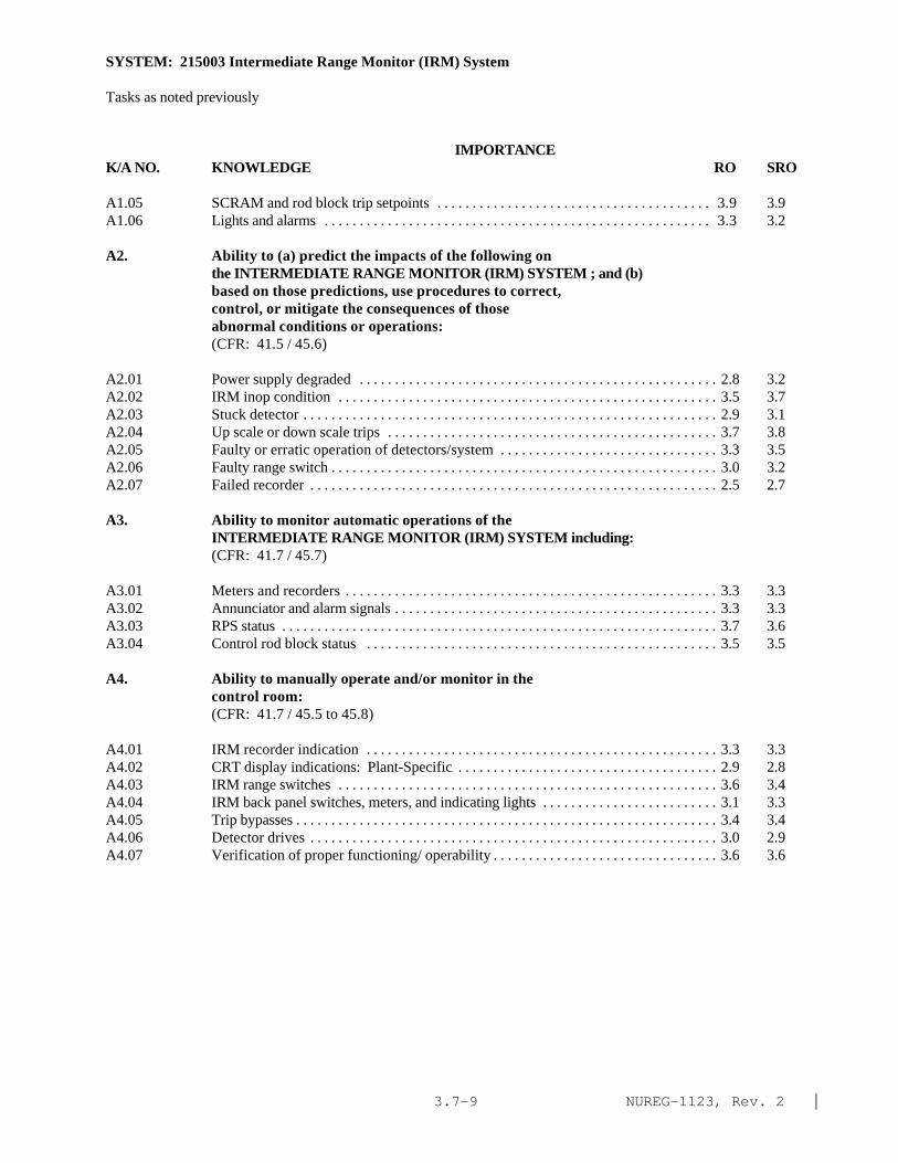
NUREG-1123, Rev. 2 |3.7-9
SYSTEM: 215003 Intermediate Range Monitor (IRM) System
Tasks as noted previously
IMPORTANCE K/A NO. KNOWLEDGE RO SRO
A1.05 SCRAM and rod block trip setpoints . . . . . . . . . . . . . . . . . . . . . . . . . . . . . . . . . . . . . . . 3.9 3.9A1.06 Lights and alarms . . . . . . . . . . . . . . . . . . . . . . . . . . . . . . . . . . . . . . . . . . . . . . . . . . . . . . . 3.3 3.2
A2. Ability to (a) predict the impacts of the following onthe INTERMEDIATE RANGE MONITOR (IRM) SYSTEM ; and (b)based on those predictions, use procedures to correct,control, or mitigate the consequences of thoseabnormal conditions or operations:(CFR: 41.5 / 45.6)
A2.01 Power supply degraded . . . . . . . . . . . . . . . . . . . . . . . . . . . . . . . . . . . . . . . . . . . . . . . . . . . 2.8 3.2A2.02 IRM inop condition . . . . . . . . . . . . . . . . . . . . . . . . . . . . . . . . . . . . . . . . . . . . . . . . . . . . . . 3.5 3.7A2.03 Stuck detector . . . . . . . . . . . . . . . . . . . . . . . . . . . . . . . . . . . . . . . . . . . . . . . . . . . . . . . . . . . 2.9 3.1A2.04 Up scale or down scale trips . . . . . . . . . . . . . . . . . . . . . . . . . . . . . . . . . . . . . . . . . . . . . . . 3.7 3.8A2.05 Faulty or erratic operation of detectors/system . . . . . . . . . . . . . . . . . . . . . . . . . . . . . . . 3.3 3.5A2.06 Faulty range switch . . . . . . . . . . . . . . . . . . . . . . . . . . . . . . . . . . . . . . . . . . . . . . . . . . . . . . . 3.0 3.2A2.07 Failed recorder . . . . . . . . . . . . . . . . . . . . . . . . . . . . . . . . . . . . . . . . . . . . . . . . . . . . . . . . . . 2.5 2.7
A3. Ability to monitor automatic operations of theINTERMEDIATE RANGE MONITOR (IRM) SYSTEM including:(CFR: 41.7 / 45.7)
A3.01 Meters and recorders . . . . . . . . . . . . . . . . . . . . . . . . . . . . . . . . . . . . . . . . . . . . . . . . . . . . . 3.3 3.3A3.02 Annunciator and alarm signals . . . . . . . . . . . . . . . . . . . . . . . . . . . . . . . . . . . . . . . . . . . . . . 3.3 3.3A3.03 RPS status . . . . . . . . . . . . . . . . . . . . . . . . . . . . . . . . . . . . . . . . . . . . . . . . . . . . . . . . . . . . . . 3.7 3.6A3.04 Control rod block status . . . . . . . . . . . . . . . . . . . . . . . . . . . . . . . . . . . . . . . . . . . . . . . . . . 3.5 3.5
A4. Ability to manually operate and/or monitor in thecontrol room:(CFR: 41.7 / 45.5 to 45.8)
A4.01 IRM recorder indication . . . . . . . . . . . . . . . . . . . . . . . . . . . . . . . . . . . . . . . . . . . . . . . . . . 3.3 3.3A4.02 CRT display indications: Plant-Specific . . . . . . . . . . . . . . . . . . . . . . . . . . . . . . . . . . . . . 2.9 2.8A4.03 IRM range switches . . . . . . . . . . . . . . . . . . . . . . . . . . . . . . . . . . . . . . . . . . . . . . . . . . . . . . 3.6 3.4A4.04 IRM back panel switches, meters, and indicating lights . . . . . . . . . . . . . . . . . . . . . . . . . 3.1 3.3A4.05 Trip bypasses . . . . . . . . . . . . . . . . . . . . . . . . . . . . . . . . . . . . . . . . . . . . . . . . . . . . . . . . . . . . 3.4 3.4A4.06 Detector drives . . . . . . . . . . . . . . . . . . . . . . . . . . . . . . . . . . . . . . . . . . . . . . . . . . . . . . . . . . 3.0 2.9A4.07 Verification of proper functioning/ operability . . . . . . . . . . . . . . . . . . . . . . . . . . . . . . . . 3.6 3.6

NUREG-1123, Rev. 2 |3.7-10
SYSTEM: 216000 Nuclear Boiler Instrumentation
TASK: Perform lineups of the non-nuclear instrumentation system Monitor the non-nuclear instrumentation system
IMPORTANCE K/A NO. KNOWLEDGE RO SRO
K1. Knowledge of the physical connections and/or cause-effect relationships between NUCLEAR BOILERINSTRUMENTATION and the following:(CFR: 41.2 to 41.9 / 45.7 to 45.8)
K1.01 Reactor protection system . . . . . . . . . . . . . . . . . . . . . . . . . . . . . . . . . . . . . . . . . . . . . . . 3.9 4.1K1.02 PCIS/NSSSS . . . . . . . . . . . . . . . . . . . . . . . . . . . . . . . . . . . . . . . . . . . . . . . . . . . . . . . . . . . 3.8 4.0Kl.03 Reactor core isolation cooling system: Plant-Specific
. . . . . . . . . . . . . . . . . . . . . . . . . . . . . . . . . . . . . . . . . . . . . . . . . . . . . . . . . . . . . . . . . . . . . . 3.4 3.6K1.04 High pressure core spray system: Plant-Specific . . . . . . . . . . . . . . . . . . . . . . . . . . . . 3.9 4.0K1.05 Residual heat removal: Plant-Specific . . . . . . . . . . . . . . . . . . . . . . . . . . . . . . . . . . . . . 3.7 3.9K1.06 Low pressure core spray . . . . . . . . . . . . . . . . . . . . . . . . . . . . . . . . . . . . . . . . . . . . . . . . . 3.9 3.9K1.07 Automatic depressurization system . . . . . . . . . . . . . . . . . . . . . . . . . . . . . . . . . . . . . . . . 3.9 4.1K1.08 Relief/safety valves . . . . . . . . . . . . . . . . . . . . . . . . . . . . . . . . . . . . . . . . . . . . . . . . . . . . . 3.7 3.9K1.09 Redundant reactivity control/ alternate rod insertion;
Plant-Specific . . . . . . . . . . . . . . . . . . . . . . . . . . . . . . . . . . . . . . . . . . . . . . . . . . . . . . . . . 3.7 4.0K1.10 Recirculation flow control system . . . . . . . . . . . . . . . . . . . . . . . . . . . . . . . . . . . . . . . . . 3.2 3.4K1.11 MSIV leakage control system: Plant-Specific . . . . . . . . . . . . . . . . . . . . . . . . . . . . . . . 2.7 2.8K1.12 Reactor water level control system . . . . . . . . . . . . . . . . . . . . . . . . . . . . . . . . . . . . . . . . 3.6 3.7K1.13 Feedwater system . . . . . . . . . . . . . . . . . . . . . . . . . . . . . . . . . . . . . . . . . . . . . . . . . . . . . . . 3.4 3.5K1.14 High pressure coolant injection: Plant-Specific . . . . . . . . . . . . . . . . . . . . . . . . . . . . . 3.8 4.1*K1.15 Isolation condenser: Plant-Specific . . . . . . . . . . . . . . . . . . . . . . . . . . . . . . . . . . . . . . . 3.9* 4.1*K1.16 Main turbine . . . . . . . . . . . . . . . . . . . . . . . . . . . . . . . . . . . . . . . . . . . . . . . . . . . . . . . . . . . 3.0 3.1K1.17 Emergency generators . . . . . . . . . . . . . . . . . . . . . . . . . . . . . . . . . . . . . . . . . . . . . . . . . . . 3.5 3.7K1.18 Analog trip system: Plant-Specific . . . . . . . . . . . . . . . . . . . . . . . . . . . . . . . . . . . . . . . . 3.0* 3.1K1.19 Anticipated transient without scram system: Plant-
Specific . . . . . . . . . . . . . . . . . . . . . . . . . . . . . . . . . . . . . . . . . . . . . . . . . . . . . . . . . . . . . . 3.8 3.9K1.20 Process computer: Plant-Specific . . . . . . . . . . . . . . . . . . . . . . . . . . . . . . . . . . . . . . . . . 2.6 2.8K1.21 SPDS/ERIS/CRIDS/GDS: Plant-Specific . . . . . . . . . . . . . . . . . . . . . . . . . . . . . . . . . . . 2.6* 2.9*K1.22 Reactor vessel . . . . . . . . . . . . . . . . . . . . . . . . . . . . . . . . . . . . . . . . . . . . . . . . . . . . . . . . . 3.6 3.8K1.23 Recirculation system . . . . . . . . . . . . . . . . . . . . . . . . . . . . . . . . . . . . . . . . . . . . . . . . . . . 3.3 3.4
K2. Knowledge of electrical power supplies to thefollowing:(CFR: 41.7)
K2.01 Analog trip system: Plant-Specific . . . . . . . . . . . . . . . . . . . . . . . . . . . . . . . . . . . . . . . . 2.8 2.8
K3. Knowledge of the effect that a loss or malfunction ofthe NUCLEAR BOILER Instrumentation will have onfollowing:(CFR: 41.7 / 45.4)
K3.01 Reactor protection system . . . . . . . . . . . . . . . . . . . . . . . . . . . . . . . . . . . . . . . . . . . . . . . 4.0 4.3*K3.02 PCIS/NSSSS . . . . . . . . . . . . . . . . . . . . . . . . . . . . . . . . . . . . . . . . . . . . . . . . . . . . . . . . . . . 4.0 4.3*

NUREG-1123, Rev. 2 |3.7-11
SYSTEM: 216000 Nuclear Boiler Instrumentation
Tasks as noted previously
IMPORTANCE K/A NO. KNOWLEDGE RO SRO
K3.03 Reactor core isolation cooling system: Plant-Specific. . . . . . . . . . . . . . . . . . . . . . . . . . . . . . . . . . . . . . . . . . . . . . . . . . . . . . . . . . . . . . . . . . . . . . 3.5 3.8
K3.04 High pressure core spray system: Plant-Specific . . . . . . . . . . . . . . . . . . . . . . . . . . . . 3.8 4.0K3.05 Residual heat removal: Plant-Specific . . . . . . . . . . . . . . . . . . . . . . . . . . . . . . . . . . . . . 3.8 3.9K3.06 Low pressure core spray . . . . . . . . . . . . . . . . . . . . . . . . . . . . . . . . . . . . . . . . . . . . . . . . . 3.8 3.9K3.07 Automatic depressurization system . . . . . . . . . . . . . . . . . . . . . . . . . . . . . . . . . . . . . . . . 3.9 4.1K3.08 Relief/safety valves . . . . . . . . . . . . . . . . . . . . . . . . . . . . . . . . . . . . . . . . . . . . . . . . . . . . . 3.6 3.7K3.09 Redundant reactivity control/ alternate rod insertion:
Plant-Specific . . . . . . . . . . . . . . . . . . . . . . . . . . . . . . . . . . . . . . . . . . . . . . . . . . . . . . . . . 3.7 4.0K3.10 Recirculation flow control system . . . . . . . . . . . . . . . . . . . . . . . . . . . . . . . . . . . . . . . . 3.2 3.3K3.11 MSIV leakage control system: Plant-Specific . . . . . . . . . . . . . . . . . . . . . . . . . . . . . . . 2.8 2.8K3.12 Reactor water level control system . . . . . . . . . . . . . . . . . . . . . . . . . . . . . . . . . . . . . . . . 3.7 3.8K3.13 Feedwater system . . . . . . . . . . . . . . . . . . . . . . . . . . . . . . . . . . . . . . . . . . . . . . . . . . . . . . 3.4 3.5K3.14 High pressure coolant injection: Plant-Specific . . . . . . . . . . . . . . . . . . . . . . . . . . . . . 3.8 4.2*K3.15 Isolation condenser: Plant-Specific . . . . . . . . . . . . . . . . . . . . . . . . . . . . . . . . . . . . . . . 3.8 4.2*K3.16 Main turbine . . . . . . . . . . . . . . . . . . . . . . . . . . . . . . . . . . . . . . . . . . . . . . . . . . . . . . . . . . . 3.0 3.1K3.17 Emergency generators . . . . . . . . . . . . . . . . . . . . . . . . . . . . . . . . . . . . . . . . . . . . . . . . . . 3.5 3.7K3.18 Analog trip system: Plant-Specific . . . . . . . . . . . . . . . . . . . . . . . . . . . . . . . . . . . . . . . . 2.9* 3.0K3.19 Anticipated transient without scram system: Plant-
Specific . . . . . . . . . . . . . . . . . . . . . . . . . . . . . . . . . . . . . . . . . . . . . . . . . . . . . . . . . . . . . . 3.7 4.0*K3.20 Process computer: Plant-Specific . . . . . . . . . . . . . . . . . . . . . . . . . . . . . . . . . . . . . . . . 2.5 2.6K3.21 SPDS/ERIS/CRIDS/GDS: Plant-Specific . . . . . . . . . . . . . . . . . . . . . . . . . . . . . . . . . . 2.6* 2.8*K3.22 Reactor vessel . . . . . . . . . . . . . . . . . . . . . . . . . . . . . . . . . . . . . . . . . . . . . . . . . . . . . . . . . 3.2 3.3 |K3.23 Vessel temperature monitoring . . . . . . . . . . . . . . . . . . . . . . . . . . . . . . . . . . . . . . . . . . . 3.1 3.3 |K3.24 Vessel level monitoring . . . . . . . . . . . . . . . . . . . . . . . . . . . . . . . . . . . . . . . . . . . . . . . . . 3.9 4.1K3.25 Vessel pressure monitoring . . . . . . . . . . . . . . . . . . . . . . . . . . . . . . . . . . . . . . . . . . . . . . 3.9 4.1 |K3.26 Core flow monitoring . . . . . . . . . . . . . . . . . . . . . . . . . . . . . . . . . . . . . . . . . . . . . . . . . . . 3.6 3.7 |K3.27 Core differential pressure monitoring . . . . . . . . . . . . . . . . . . . . . . . . . . . . . . . . . . . . . 2.9 3.1K3.28 Loose parts detection in the primary system: Plant-
Specific . . . . . . . . . . . . . . . . . . . . . . . . . . . . . . . . . . . . . . . . . . . . . . . . . . . . . . . . . . . . . . 2.0* 2.1*K3.29 Jet pump flow monitoring: Plant-Specific . . . . . . . . . . . . . . . . . . . . . . . . . . . . . . . . . . 3.1 3.2K3.30 Recirculation system . . . . . . . . . . . . . . . . . . . . . . . . . . . . . . . . . . . . . . . . . . . . . . . . . . . 3.2 3.3
K4. Knowledge of NUCLEAR BOILER INSTRUMENTATION designfeature(s) and/or interlocks which provide for thefollowing:(CFR: 41.7)
K4.01 Reading of nuclear boiler parameters outside thecontrol room . . . . . . . . . . . . . . . . . . . . . . . . . . . . . . . . . . . . . . . . . . . . . . . . . . . . . . . . . . 3.6 3.6
K4.02 Physical separation of sensors . . . . . . . . . . . . . . . . . . . . . . . . . . . . . . . . . . . . . . . . . . . . 3.0 3.2K4.03 Redundancy of sensors . . . . . . . . . . . . . . . . . . . . . . . . . . . . . . . . . . . . . . . . . . . . . . . . . . 3.4 3.6K4.04 Inputs to the reactor protection system . . . . . . . . . . . . . . . . . . . . . . . . . . . . . . . . . . . . . 3.7 3.8 |K4.05 Initiation of the emergency core cooling systems . . . . . . . . . . . . . . . . . . . . . . . . . . . . 3.9 4.1 |K4.06 Initiation of the PCIS/NSSSS . . . . . . . . . . . . . . . . . . . . . . . . . . . . . . . . . . . . . . . . . . . . . 3.8 4.0K4.07 Recirculation pump protection: Plant-Specific . . . . . . . . . . . . . . . . . . . . . . . . . . . . . . 2.9 3.0

NUREG-1123, Rev. 2 |3.7-12
SYSTEM: 216000 Nuclear Boiler Instrumentation
Tasks as noted previously
IMPORTANCE K/A NO. KNOWLEDGE RO SRO
K4.08 Protection for the main turbine from high moisturecarryover . . . . . . . . . . . . . . . . . . . . . . . . . . . . . . . . . . . . . . . . . . . . . . . . . . . . . . . . . . . . . 2.9 3.0
K4.09 Protection against filling the main steam lines fromthe feed system . . . . . . . . . . . . . . . . . . . . . . . . . . . . . . . . . . . . . . . . . . . . . . . . . . . . . . . . 3.3 3.3
K4.10 Automatic recirculation pump speed control: Plant-Specific . . . . . . . . . . . . . . . . . . . . . . . . . . . . . . . . . . . . . . . . . . . . . . . . . . . . . . . . . . . . . . 2.9 3.1
K4.11 Inputs to the redundant reactivity controlsystem/alternate rod insertion: Plant-Specific . . . . . . . . . . . . . . . . . . . . . . . . . . . . . . 4.0 4.0
K4.12 Reactor vessel overpressure protection . . . . . . . . . . . . . . . . . . . . . . . . . . . . . . . . . . . . 3.7 3.9K4.13 Overpressure protection for various low-pressure systems . . . . . . . . . . . . . . . . . . . . . . . . . . . . . . . . . . . . . . . . . . . . . . . . . . . . . . . . . . . . . . . . . . 3.4 3.4K4.14 Temperature compensation for reactor water level
indication: Plant-Specific . . . . . . . . . . . . . . . . . . . . . . . . . . . . . . . . . . . . . . . . . . . . . . . 3.3 3.4
K5. Knowledge of the operational implications of thefollowing concepts as they apply to NUCLEAR BOILERINSTRUMENTATION :(CFR: 41.5 / 45.3)
K5.01 Vessel level measurement . . . . . . . . . . . . . . . . . . . . . . . . . . . . . . . . . . . . . . . . . . . . . . . 3.1 3.2K5.02 Vessel pressure measurement . . . . . . . . . . . . . . . . . . . . . . . . . . . . . . . . . . . . . . . . . . . . 3.1 3.2K5.03 Vessel temperature measurement . . . . . . . . . . . . . . . . . . . . . . . . . . . . . . . . . . . . . . . . . 3.0 3.2K5.04 Vessel differential pressure measurement . . . . . . . . . . . . . . . . . . . . . . . . . . . . . . . . . . 2.8 2.9K5.05 Vessel vibration measurement (loose parts monitor) . . . . . . . . . . . . . . . . . . . . . . . . . 2.3 2.3K5.06 Rapid vessel depressurization effects on vessel level
indications . . . . . . . . . . . . . . . . . . . . . . . . . . . . . . . . . . . . . . . . . . . . . . . . . . . . . . . . . . . . 3.4 3.6K5.07 Elevated containment temperature effects on level
indication . . . . . . . . . . . . . . . . . . . . . . . . . . . . . . . . . . . . . . . . . . . . . . . . . . . . . . . . . . . . . 3.6 3.8K5.08 Steam flow effect on reactor water level . . . . . . . . . . . . . . . . . . . . . . . . . . . . . . . . . . . 3.1 3.2K5.09 Recirculation flow effects on level indications:
Design-Specific . . . . . . . . . . . . . . . . . . . . . . . . . . . . . . . . . . . . . . . . . . . . . . . . . . . . . . . . 2.9 2.9K5.10 Indicated level versus actual vessel level during
vessel heatups or cooldowns . . . . . . . . . . . . . . . . . . . . . . . . . . . . . . . . . . . . . . . . . . . . . 3.1 3.3K5.11 Indicated vessel temperature response during rapid
heatups or cooldowns . . . . . . . . . . . . . . . . . . . . . . . . . . . . . . . . . . . . . . . . . . . . . . . . . . . 3.2 3.3K5.12 Effects on level indication due to rapid changes in
void fraction . . . . . . . . . . . . . . . . . . . . . . . . . . . . . . . . . . . . . . . . . . . . . . . . . . . . . . . . . . . 3.2 3.3K5.13 Reference leg flashing: Design-Specific . . . . . . . . . . . . . . . . . . . . . . . . . . . . . . . . . . . 3.5 3.6K5.14 Density . . . . . . . . . . . . . . . . . . . . . . . . . . . . . . . . . . . . . . . . . . . . . . . . . . . . . . . . . . . . . . . 2.6 2.6K5.15 Static pressure . . . . . . . . . . . . . . . . . . . . . . . . . . . . . . . . . . . . . . . . . . . . . . . . . . . . . . . . . 2.2* 2.2*K5.16 Dynamic pressure . . . . . . . . . . . . . . . . . . . . . . . . . . . . . . . . . . . . . . . . . . . . . . . . . . . . . . 2.1* 2.1*
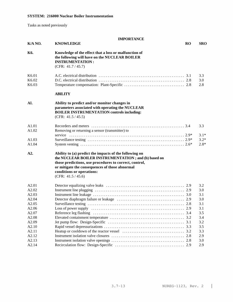
NUREG-1123, Rev. 2 |3.7-13
SYSTEM: 216000 Nuclear Boiler Instrumentation
Tasks as noted previously
IMPORTANCE K/A NO. KNOWLEDGE RO SRO
K6. Knowledge of the effect that a loss or malfunction ofthe following will have on the NUCLEAR BOILERINSTRUMENTATION :(CFR: 41.7 / 45.7)
K6.01 A.C. electrical distribution . . . . . . . . . . . . . . . . . . . . . . . . . . . . . . . . . . . . . . . . . . . . . . . 3.1 3.3K6.02 D.C. electrical distribution . . . . . . . . . . . . . . . . . . . . . . . . . . . . . . . . . . . . . . . . . . . . . . . 2.8 3.0K6.03 Temperature compensation: Plant-Specific . . . . . . . . . . . . . . . . . . . . . . . . . . . . . . . . . 2.8 2.8
ABILITY
Al. Ability to predict and/or monitor changes inparameters associated with operating the NUCLEARBOILER INSTRUMENTATION controls including:(CFR: 41.5 / 45.5)
A1.01 Recorders and meters . . . . . . . . . . . . . . . . . . . . . . . . . . . . . . . . . . . . . . . . . . . . . . . . . . . 3.4 3.3A1.02 Removing or returning a sensor (transmitter) to
service . . . . . . . . . . . . . . . . . . . . . . . . . . . . . . . . . . . . . . . . . . . . . . . . . . . . . . . . . . . . . . . 2.9* 3.1*A1.03 Surveillance testing . . . . . . . . . . . . . . . . . . . . . . . . . . . . . . . . . . . . . . . . . . . . . . . . . . . . . 2.9* 3.2*A1.04 System venting . . . . . . . . . . . . . . . . . . . . . . . . . . . . . . . . . . . . . . . . . . . . . . . . . . . . . . . . . 2.6* 2.8*
A2. Ability to (a) predict the impacts of the following onthe NUCLEAR BOILER INSTRUMENTATION ; and (b) based onthose predictions, use procedures to correct, control,or mitigate the consequences of those abnormalconditions or operations:(CFR: 41.5 / 45.6)
A2.01 Detector equalizing valve leaks . . . . . . . . . . . . . . . . . . . . . . . . . . . . . . . . . . . . . . . . . . . 2.9 3.2A2.02 Instrument line plugging . . . . . . . . . . . . . . . . . . . . . . . . . . . . . . . . . . . . . . . . . . . . . . . . . 2.9 3.0A2.03 Instrument line leakage . . . . . . . . . . . . . . . . . . . . . . . . . . . . . . . . . . . . . . . . . . . . . . . . . . 3.0 3.1A2.04 Detector diaphragm failure or leakage . . . . . . . . . . . . . . . . . . . . . . . . . . . . . . . . . . . . . 2.9 3.0A2.05 Surveillance testing . . . . . . . . . . . . . . . . . . . . . . . . . . . . . . . . . . . . . . . . . . . . . . . . . . . . . 2.8 3.1A2.06 Loss of power supply . . . . . . . . . . . . . . . . . . . . . . . . . . . . . . . . . . . . . . . . . . . . . . . . . . . 2.9 3.1A2.07 Reference leg flashing . . . . . . . . . . . . . . . . . . . . . . . . . . . . . . . . . . . . . . . . . . . . . . . . . . 3.4 3.5A2.08 Elevated containment temperature . . . . . . . . . . . . . . . . . . . . . . . . . . . . . . . . . . . . . . . . . 3.2 3.4A2.09 Jet pump flow: Design-Specific . . . . . . . . . . . . . . . . . . . . . . . . . . . . . . . . . . . . . . . . . . 3.1 3.2A2.10 Rapid vessel depressurizations . . . . . . . . . . . . . . . . . . . . . . . . . . . . . . . . . . . . . . . . . . . . 3.3 3.5A2.11 Heatup or cooldown of the reactor vessel . . . . . . . . . . . . . . . . . . . . . . . . . . . . . . . . . . 3.2 3.3A2.12 Instrument isolation valve closures . . . . . . . . . . . . . . . . . . . . . . . . . . . . . . . . . . . . . . . . 2.8 2.9A2.13 Instrument isolation valve openings . . . . . . . . . . . . . . . . . . . . . . . . . . . . . . . . . . . . . . . . 2.8 3.0A2.14 Recirculation flow: Design-Specific . . . . . . . . . . . . . . . . . . . . . . . . . . . . . . . . . . . . . . 2.9 2.9

NUREG-1123, Rev. 2 |3.7-14
SYSTEM: 216000 Nuclear Boiler Instrumentation
Tasks as noted previously
IMPORTANCE K/A NO. KNOWLEDGE RO SRO
A3. Ability to monitor automatic operations of the NUCLEARBOILER Instrumentation including:(CFR: 41.7 / 45.7)
A3.01 Relationship between meter/recorder readings andactual parameter values: Plant-Specific . . . . . . . . . . . . . . . . . . . . . . . . . . . . . . . . . . . . 3.4 3.4
A4. Ability to manually operate and/or monitor in thecontrol room:(CFR: 41.7 / 45.5 to 45.8)
A4.01 Recorders . . . . . . . . . . . . . . . . . . . . . . . . . . . . . . . . . . . . . . . . . . . . . . . . . . . . . . . . . . . . . 3.3 3.1A4.02 Channel select controls . . . . . . . . . . . . . . . . . . . . . . . . . . . . . . . . . . . . . . . . . . . . . . . . . 3.3 3.1A4.03 Process computer: Design-Specific . . . . . . . . . . . . . . . . . . . . . . . . . . . . . . . . . . . . . . . 3.0 3.1

NUREG-1123, Rev. 2 |3.7-15
SYSTEM: 272000 Radiation Monitoring System
TASK: Perform lineups of the area radiation monitoring systemOperate area radiation monitorsMonitor area radiationPerform lineups of process radiation monitoring systemOperate process radiation monitorsMonitor process radiation monitor operation
IMPORTANCE K/A NO. KNOWLEDGE RO SRO
K1. Knowledge of the physical connections and/or cause-effect relationships between RADIATION MONITORINGSYSTEM and the following:(CFR: 41.2 to 41.9 / 45.7 to 45.8)
K1.01 Main steam system . . . . . . . . . . . . . . . . . . . . . . . . . . . . . . . . . . . . . . . . . . . . . . . . . . . . . 3.6 3.8K1.02 Offgas system (augmented offgas): Plant-Specific . . . . . . . . . . . . . . . . . . . . . . . . . . 3.2 3.5K1.03 Stack gas: Plant-Specific . . . . . . . . . . . . . . . . . . . . . . . . . . . . . . . . . . . . . . . . . . . . . . . . 3.3 3.6K1.04 Applicable component cooling water system . . . . . . . . . . . . . . . . . . . . . . . . . . . . . . . . 2.9 2.9K1.05 Radwaste system . . . . . . . . . . . . . . . . . . . . . . . . . . . . . . . . . . . . . . . . . . . . . . . . . . . . . . . 2.8 3.1 |K1.06 Reactor building ventilation system: Plant-Specific . . . . . . . . . . . . . . . . . . . . . . . . . . 3.2 3.3K1.07 Isolation condenser: Plant-Specific . . . . . . . . . . . . . . . . . . . . . . . . . . . . . . . . . . . . . . . 3.0 3.2K1.08 Reactor protection system . . . . . . . . . . . . . . . . . . . . . . . . . . . . . . . . . . . . . . . . . . . . . . . 3.6 3.9K1.09 Primary containment isolation system . . . . . . . . . . . . . . . . . . . . . . . . . . . . . . . . . . . . . 3.6 3.8K1.10 Reactor building refuel floor: Plant-Specific . . . . . . . . . . . . . . . . . . . . . . . . . . . . . . . 3.4 3.6K1.11 Reactor building overhead crane; Plant-Specific . . . . . . . . . . . . . . . . . . . . . . . . . . . . . 2.1* 2.4*K1.12 Reactor building . . . . . . . . . . . . . . . . . . . . . . . . . . . . . . . . . . . . . . . . . . . . . . . . . . . . . . . . 3.1 3.2K1.13 Turbine building . . . . . . . . . . . . . . . . . . . . . . . . . . . . . . . . . . . . . . . . . . . . . . . . . . . . . . . . 2.9 3.0K1.14 Radwaste building: Plant-Specific . . . . . . . . . . . . . . . . . . . . . . . . . . . . . . . . . . . . . . . . 2.7 2.8K1.15 Filter building: Plant-Specific . . . . . . . . . . . . . . . . . . . . . . . . . . . . . . . . . . . . . . . . . . . . 2.8 3.0K1.16 Process computer . . . . . . . . . . . . . . . . . . . . . . . . . . . . . . . . . . . . . . . . . . . . . . . . . . . . . . . 2.2* 2.3*K1.17 SPDS/ERIS/CRIDS/GDS: Plant-Specific . . . . . . . . . . . . . . . . . . . . . . . . . . . . . . . . . . 2.4 2.7K1.18 Primary containment/containment building: Plant-
Specific . . . . . . . . . . . . . . . . . . . . . . . . . . . . . . . . . . . . . . . . . . . . . . . . . . . . . . . . . . . . . . 3.1 3.1K1.19 Drywell . . . . . . . . . . . . . . . . . . . . . . . . . . . . . . . . . . . . . . . . . . . . . . . . . . . . . . . . . . . . . . . 3.1 3.2K1.20 †Auxiliary building: Plant-Specific . . . . . . . . . . . . . . . . . . . . . . . . . . . . . . . . . . . . . . . 2.8 3.0K1.21 Circulating water: Plant-Specific . . . . . . . . . . . . . . . . . . . . . . . . . . . . . . . . . . . . . . . . . 2.3 2.4K1.22 Fuel building: mark-III . . . . . . . . . . . . . . . . . . . . . . . . . . . . . . . . . . . . . . . . . . . . . . . . . . 3.0 3.4K1.23 Continuous air monitoring: Plant-Specific . . . . . . . . . . . . . . . . . . . . . . . . . . . . . . . . . 3.0 3.3
K2. Knowledge of electrical power supplies to thefollowing:(CFR: 41.7)
K2.01 Main steamline radiation monitors . . . . . . . . . . . . . . . . . . . . . . . . . . . . . . . . . . . . . . . . . 2.5 2.8K2.02 Offgas radiation monitoring system . . . . . . . . . . . . . . . . . . . . . . . . . . . . . . . . . . . . . . . . 2.5 2.8K2.03 Stack gas radiation monitoring system . . . . . . . . . . . . . . . . . . . . . . . . . . . . . . . . . . . . . 2.5 2.8K2.04 Process liquid radiation monitoring system . . . . . . . . . . . . . . . . . . . . . . . . . . . . . . . . . 2.3 2.5

NUREG-1123, Rev. 2 |3.7-16
SYSTEM: 272000 Radiation Monitoring System
Tasks as noted previously
IMPORTANCE K/A NO. KNOWLEDGE RO SRO
K2.05 Reactor building ventilation monitors: Plant-Specific. . . . . . . . . . . . . . . . . . . . . . . . . . . . . . . . . . . . . . . . . . . . . . . . . . . . . . . . . . . . . . . . . . . . . . 2.6 2.9
K2.06 Area radiation monitors . . . . . . . . . . . . . . . . . . . . . . . . . . . . . . . . . . . . . . . . . . . . . . . . . 2.1* 2.2*K2.07 Control room ventilation monitors: Plant-Specific . . . . . . . . . . . . . . . . . . . . . . . . . . 2.2* 2.4*
K3 Knowledge of the effect that a loss or malfunction ofthe RADIATION MONITORING System will have onfollowing:(CFR: 41.5 / 45.3)
K3.01 †Station liquid effluent release monitoring . . . . . . . . . . . . . . . . . . . . . . . . . . . . . . . . . 3.2 3.8K3.02 †Station gaseous effluent release monitoring . . . . . . . . . . . . . . . . . . . . . . . . . . . . . . . 3.1 3.8K3.03 Station area radiation monitoring . . . . . . . . . . . . . . . . . . . . . . . . . . . . . . . . . . . . . . . . . . 3.2 3.4K3.04 Main steam system . . . . . . . . . . . . . . . . . . . . . . . . . . . . . . . . . . . . . . . . . . . . . . . . . . . . . 3.7 3.8K3.05 Offgas system . . . . . . . . . . . . . . . . . . . . . . . . . . . . . . . . . . . . . . . . . . . . . . . . . . . . . . . . . 3.5 3.7K3.06 Reactor building ventilation: Plant-Specific . . . . . . . . . . . . . . . . . . . . . . . . . . . . . . . . 3.4 3.6K3.07 Reactor building overhead crane operation: Plant-
Specific . . . . . . . . . . . . . . . . . . . . . . . . . . . . . . . . . . . . . . . . . . . . . . . . . . . . . . . . . . . . . . 2.4* 3.0K3.08 †Auxiliary building ventilation: Plant-Specific . . . . . . . . . . . . . . . . . . . . . . . . . . . . . . 2.9 3.3K3.09 Radwaste building ventilation: Plant-Specific . . . . . . . . . . . . . . . . . . . . . . . . . . . . . . . 2.8 3.1K3.10 Control room ventilation: Plant-Specific . . . . . . . . . . . . . . . . . . . . . . . . . . . . . . . . . . 2.9 3.3
K4. Knowledge of RADIATION MONITORING System designfeature(s) and/or interlocks which provide for thefollowing:(CFR: 41.7)
K4.01 Redundancy . . . . . . . . . . . . . . . . . . . . . . . . . . . . . . . . . . . . . . . . . . . . . . . . . . . . . . . . . . . 2.7 2.8K4.02 Automatic actions to contain the radioactive release
in the event that the predetermined release rates areexceeded . . . . . . . . . . . . . . . . . . . . . . . . . . . . . . . . . . . . . . . . . . . . . . . . . . . . . . . . . . . . . . 3.7 4.1
K4.03 Fail safe tripping of process radiation monitoringlogic during conditions of instrument failure . . . . . . . . . . . . . . . . . . . . . . . . . . . . . . . . 3.6 3.9
K5. Knowledge of the operational implications of thefollowing concepts as they apply to RADIATIONMONITORING SYSTEM :(CFR: 41.7 / 45.4)
K5.01 Hydrogen injection operation's effect on processradiation indications: Plant-Specific . . . . . . . . . . . . . . . . . . . . . . . . . . . . . . . . . . . . . . 3.2 3.5

NUREG-1123, Rev. 2 |3.7-17
SYSTEM: 272000 Radiation Monitoring System
Tasks as noted previously
IMPORTANCE K/A NO. KNOWLEDGE RO SRO
K6 Knowledge of the effect that a loss or malfunction ofthe following will have on the RADIATION MONITORINGSYSTEM :(CFR: 41.7 / 45.7)
K6.01 Reactor protection system . . . . . . . . . . . . . . . . . . . . . . . . . . . . . . . . . . . . . . . . . . . . . . . 3.0 3.2K6.02 D.C. power . . . . . . . . . . . . . . . . . . . . . . . . . . . . . . . . . . . . . . . . . . . . . . . . . . . . . . . . . . . . 2.5 2.7K6.03 A.C. power . . . . . . . . . . . . . . . . . . . . . . . . . . . . . . . . . . . . . . . . . . . . . . . . . . . . . . . . . . . . 2.8 3.0K6.04 Process computer . . . . . . . . . . . . . . . . . . . . . . . . . . . . . . . . . . . . . . . . . . . . . . . . . . . . . . 2.0* 2.2*K6.05 SPDS/ERIS/CRID/GDS: Plant-Specific . . . . . . . . . . . . . . . . . . . . . . . . . . . . . . . . . . . 2.1* 2.4*K6.06 Continuous air monitoring: Plant-Specific . . . . . . . . . . . . . . . . . . . . . . . . . . . . . . . . . 2.4 2.6
ABILITY
A1. Ability to predict and/or monitor changes inparameters associated with operating the RADIATIONMONITORING SYSTEM controls including:(CFR: 41.5 / 45.5)
A1.01 Lights, alarms, and indications associated with normaloperations . . . . . . . . . . . . . . . . . . . . . . . . . . . . . . . . . . . . . . . . . . . . . . . . . . . . . . . . . . . . . 3.2 3.2
A1.02 Lights, alarms, and indications associated withsurveillance testing . . . . . . . . . . . . . . . . . . . . . . . . . . . . . . . . . . . . . . . . . . . . . . . . . . . . . 2.9 2.9
A2. Ability to (d) predict the impacts of the following onthe RADIATION MONITORING SYSTEM ; and (b) based onthose predictions, use procedures to correct, control,or mitigate the consequences of those abnormalconditions or operations:(CFR: 41.5 / 45.6)
A2.01 Fuel element failure . . . . . . . . . . . . . . . . . . . . . . . . . . . . . . . . . . . . . . . . . . . . . . . . . . . . 3.7 4.1A2.02 Reactor protection system power failure . . . . . . . . . . . . . . . . . . . . . . . . . . . . . . . . . . . 3.3 3.6A2.03 A.C. electrical failure . . . . . . . . . . . . . . . . . . . . . . . . . . . . . . . . . . . . . . . . . . . . . . . . . . . 2.9 3.1A2.04 D.C. electrical failure . . . . . . . . . . . . . . . . . . . . . . . . . . . . . . . . . . . . . . . . . . . . . . . . . . . 2.7 2.8A2.05 Loss of dilution steam . . . . . . . . . . . . . . . . . . . . . . . . . . . . . . . . . . . . . . . . . . . . . . . . . . 2.5 2.6A2.06 Downscale trips . . . . . . . . . . . . . . . . . . . . . . . . . . . . . . . . . . . . . . . . . . . . . . . . . . . . . . . . 2.8 2.9A2.07 Hydrogen injection operation: Plant-Specific . . . . . . . . . . . . . . . . . . . . . . . . . . . . . . . 2.6 2.8A2.08 Offgas system failure . . . . . . . . . . . . . . . . . . . . . . . . . . . . . . . . . . . . . . . . . . . . . . . . . . . 2.9 3.1A2.09 Low fuel pool level . . . . . . . . . . . . . . . . . . . . . . . . . . . . . . . . . . . . . . . . . . . . . . . . . . . . . 3.1 3.3A2.10 Loss of coolant accident . . . . . . . . . . . . . . . . . . . . . . . . . . . . . . . . . . . . . . . . . . . . . . . . . 3.9 4.1A2.11 Leakage and/or breaks from contaminated systems to
atmosphere or to other process systems . . . . . . . . . . . . . . . . . . . . . . . . . . . . . . . . . . . . 3.4 3.7A2.12 †Refuel floor handling accidents/operations . . . . . . . . . . . . . . . . . . . . . . . . . . . . . . . . 3.3 4.0A2.13 Low reactor water level during refueling operations . . . . . . . . . . . . . . . . . . . . . . . . . . 3.3 3.8A2.14 Loss of, or inadequate, shielding . . . . . . . . . . . . . . . . . . . . . . . . . . . . . . . . . . . . . . . . . . 3.2 3.5A2.15 Maintenance operations . . . . . . . . . . . . . . . . . . . . . . . . . . . . . . . . . . . . . . . . . . . . . . . . . 2.5 2.7

NUREG-1123, Rev. 2 |3.7-18
SYSTEM: 272000 Radiation Monitoring System
Tasks as noted previously
IMPORTANCE K/A NO. ABILITY RO SRO
A2.16 Instrument malfunctions . . . . . . . . . . . . . . . . . . . . . . . . . . . . . . . . . . . . . . . . . . . . . . . . . 2.7 2.9
A3. Ability to monitor automatic operations of theRADIATION MONITORING SYSTEM including:(CFR: 41.7 / 45.7)
A3.01 Main steam isolation indications . . . . . . . . . . . . . . . . . . . . . . . . . . . . . . . . . . . . . . . . . . 3.8 3.9A3.02 Offgas system isolation indications . . . . . . . . . . . . . . . . . . . . . . . . . . . . . . . . . . . . . . . 3.6 3.7A3.03 Liquid radwaste isolation indications . . . . . . . . . . . . . . . . . . . . . . . . . . . . . . . . . . . . . . 3.1 3.5A3.04 Radwaste handing interlocks . . . . . . . . . . . . . . . . . . . . . . . . . . . . . . . . . . . . . . . . . . . . . 2.3 2.8A3.05 Refuel floor overhead crane operation interrupt:
Plant-Specific . . . . . . . . . . . . . . . . . . . . . . . . . . . . . . . . . . . . . . . . . . . . . . . . . . . . . . . . . 3.0 3.1A3.06 Ventilation system isolation indications . . . . . . . . . . . . . . . . . . . . . . . . . . . . . . . . . . . . 3.4 3.4|A3.07 Recorder indications . . . . . . . . . . . . . . . . . . . . . . . . . . . . . . . . . . . . . . . . . . . . . . . . . . . . 2.8 2.9|A3.08 Meter indications . . . . . . . . . . . . . . . . . . . . . . . . . . . . . . . . . . . . . . . . . . . . . . . . . . . . . . 2.9 2.9A3.09 Containment isolation indications . . . . . . . . . . . . . . . . . . . . . . . . . . . . . . . . . . . . . . . . . 3.6 3.5A3.10 Lights and alarms . . . . . . . . . . . . . . . . . . . . . . . . . . . . . . . . . . . . . . . . . . . . . . . . . . . . . . . 3.3 3.2A3.11 Circulating water system blowdown isolations: Plant-
Specific . . . . . . . . . . . . . . . . . . . . . . . . . . . . . . . . . . . . . . . . . . . . . . . . . . . . . . . . . . . . . . 2.6 2.7
A4. Ability to manually operate and/or monitor in thecontrol room:(CFR: 41.7 / 45.5 to 45.8)
A4.01 Recorder indications . . . . . . . . . . . . . . . . . . . . . . . . . . . . . . . . . . . . . . . . . . . . . . . . . . . . 2.9 2.9A4.02 Meter indications . . . . . . . . . . . . . . . . . . . . . . . . . . . . . . . . . . . . . . . . . . . . . . . . . . . . . . 3.0 3.0A4.03 Power supply status indicators . . . . . . . . . . . . . . . . . . . . . . . . . . . . . . . . . . . . . . . . . . . . 2.6 2.6|A4.04 SPDS/ERIS/CRID/GDS . . . . . . . . . . . . . . . . . . . . . . . . . . . . . . . . . . . . . . . . . . . . . . . . . 2.5* 2.7*|A4.05 †Convert process radiation monitor readings to offsite
release rates: Plant-Specific . . . . . . . . . . . . . . . . . . . . . . . . . . . . . . . . . . . . . . . . . . . . 2.3* 3.7*A4.06 †Manually trip process radiation monitor logic . . . . . . . . . . . . . . . . . . . . . . . . . . . . . . 2.9 3.2

NUREG-1123, Rev. 2 |3.7-19
SYSTEM: 212000 Reactor Protection System
TASK: Energize the reactor protection system Place a reactor protection channel in the tripped condition Bypass a trip condition on a reactor protection channel (bypass an average power range monitor trip) Deenergize the reactor protection system Monitor the reactor protection system Operate the reactor protection system MG sets Operate the reactor mode switch Operate the reactor trip breakers Shift the reactor protection system bus to the alternate power supplyConduct manual SCRAM functional test Conduct mode switch in shutdown functional test Conduct RPS channel test switch functional test
IMPORTANCE K/A NO. KNOWLEDGE RO SRO
K1. Knowledge of the physical connections and/or cause-effect relationships between REACTOR PROTECTION SYSTEMand the following:(CFR: 41.2 to 41.9 / 45.7 to 45.8)
K1.01 Nuclear instrumentation . . . . . . . . . . . . . . . . . . . . . . . . . . . . . . . . . . . . . . . . . . . . . . . . . . 3.7 3.9K1.02 Nuclear boiler instrumentation . . . . . . . . . . . . . . . . . . . . . . . . . . . . . . . . . . . . . . . . . . . . . 3.7 3.9K1.03 Recirculation system . . . . . . . . . . . . . . . . . . . . . . . . . . . . . . . . . . . . . . . . . . . . . . . . . . . . . 3.4 3.6K1.04 A.C. electrical distribution . . . . . . . . . . . . . . . . . . . . . . . . . . . . . . . . . . . . . . . . . . . . . . . . 3.4 3.6K1.05 Process radiation monitoring system . . . . . . . . . . . . . . . . . . . . . . . . . . . . . . . . . . . . . . . . 3.3 3.6K1.06 Control rod drive hydraulic system . . . . . . . . . . . . . . . . . . . . . . . . . . . . . . . . . . . . . . . . . 3.5 3.6K1.07 Relief/safety valves (low-low-set logic): Plant- Specific . . . . . . . . . . . . . . . . . . . . . . . . . . . . . . . . . . . . . . . . . . . . . . . . . . . . . . . . . . . . . . . . . . . 3.3 3.5K1.08 Control rod and drive mechanism . . . . . . . . . . . . . . . . . . . . . . . . . . . . . . . . . . . . . . . . . . . 3.0 3.1K1.09 Process computer . . . . . . . . . . . . . . . . . . . . . . . . . . . . . . . . . . . . . . . . . . . . . . . . . . . . . . . . 2.3 2.4K1.10 Main turbine . . . . . . . . . . . . . . . . . . . . . . . . . . . . . . . . . . . . . . . . . . . . . . . . . . . . . . . . . . . . 3.2 3.4K1.11 Condenser vacuum . . . . . . . . . . . . . . . . . . . . . . . . . . . . . . . . . . . . . . . . . . . . . . . . . . . . . . . 3.3 3.5K1.12 Reactor/turbine pressure control system: Plant-
Specific . . . . . . . . . . . . . . . . . . . . . . . . . . . . . . . . . . . . . . . . . . . . . . . . . . . . . . . . . . . . . . . . 3.4 3.6K1.13 Containment pressure . . . . . . . . . . . . . . . . . . . . . . . . . . . . . . . . . . . . . . . . . . . . . . . . . . . . 3.5 3.6K1.14 Main steam system . . . . . . . . . . . . . . . . . . . . . . . . . . . . . . . . . . . . . . . . . . . . . . . . . . . . . . . 3.6 3.7K1.15 SCRAM air header pressure . . . . . . . . . . . . . . . . . . . . . . . . . . . . . . . . . . . . . . . . . . . . . . . 3.8 3.9
K2. Knowledge of electrical power supplies to thefollowing:(CFR: 41.7)
K2.01 RPS motor-generator sets . . . . . . . . . . . . . . . . . . . . . . . . . . . . . . . . . . . . . . . . . . . . . . . . . 3.2 3.3K2.02 Analog trip system logic cabinets . . . . . . . . . . . . . . . . . . . . . . . . . . . . . . . . . . . . . . . . . . . 2.7 2.9

NUREG-1123, Rev. 2 |3.7-20
SYSTEM: 212000 Reactor Protection System
Tasks as noted previously
IMPORTANCE K/A NO. KNOWLEDGE RO SRO
K3. Knowledge of the effect that a loss or malfunction ofthe REACTOR PROTECTION SYSTEM will have on following:(CFR: 41.7 / 45.4)
K3.01 Process radiation monitoring 3.0 3.2K3.02 Primary containment isolation system/nuclear steam
supply shut-off: Plant-Specific 3.7 3.9K3.03 Local power range monitoring system: Plant-Specific 3.3 3.4K3.04 Average power range monitoring system: Plant-Specific
3.5 3.6K3.05 RPS logic channels 3.7 3.8K3.06 Scram air header solenoid operated valves 4.0 4.1K3.07 Reactor power (thermal heat flux) 3.8 3.9K3.08 Reactor coolant primary system integrity 3.6 3.8K3.09 The magnitude of heat energy that must be absorbed by
the containment during accident/transient conditions 3.2 3.6K3.10 The ability of the core cooling systems to provide
adequate core cooling during loss of coolant accidents 3.5 3.9K3.11 Recirculation system 3.0 3.3K3.12 Secondary containment integrity 3.2 3.3
K4. Knowledge of REACTOR PROTECTION SYSTEM designfeature(s) and/or interlocks which provide for thefollowing:
(CFR: 41.7)
K4.01 System redundancy and reliability . . . . . . . . . . . . . . . . . . . . . . . . . . . . . . . . . . . . . . . . . 3.4 3.6K4.02 The prevention of a reactor SCRAM following a single
component failure . . . . . . . . . . . . . . . . . . . . . . . . . . . . . . . . . . . . . . . . . . . . . . . . . . . . . . 3.5 3.7K4.03 The prevention of supplying power to a given RPS bus
from multiple sources simultaneously . . . . . . . . . . . . . . . . . . . . . . . . . . . . . . . . . . . . . 3.0* 3.1*K4.04 The prevention of supplying both RPS buses
simultaneously from the alternate power source:Plant-Specific . . . . . . . . . . . . . . . . . . . . . . . . . . . . . . . . . . . . . . . . . . . . . . . . . . . . . . . . . 3.1 3.1
K4.05 Functional testing of the system while maintainingpower operation . . . . . . . . . . . . . . . . . . . . . . . . . . . . . . . . . . . . . . . . . . . . . . . . . . . . . . . . 3.4 3.6
K4.06 Select rod insertion: Plant-Specific . . . . . . . . . . . . . . . . . . . . . . . . . . . . . . . . . . . . . . . 3.0 3.0K4.07 Manual system activation (trip) . . . . . . . . . . . . . . . . . . . . . . . . . . . . . . . . . . . . . . . . . . . 4.1* 4.1K4.08 Complete control rod insertion following SCRAM signal
generation . . . . . . . . . . . . . . . . . . . . . . . . . . . . . . . . . . . . . . . . . . . . . . . . . . . . . . . . . . . . . 4.2* 4.2*K4.09 Control rod insertion following RPS system electrical
failure . . . . . . . . . . . . . . . . . . . . . . . . . . . . . . . . . . . . . . . . . . . . . . . . . . . . . . . . . . . . . . . . 3.8 3.9K4.10 Individual rod SCRAM testing . . . . . . . . . . . . . . . . . . . . . . . . . . . . . . . . . . . . . . . . . . . . 3.3 3.6K4.11 Operation with shorting links removed: Plant-Specific
. . . . . . . . . . . . . . . . . . . . . . . . . . . . . . . . . . . . . . . . . . . . . . . . . . . . . . . . . . . . . . . . . . . . . . 3.3 3.5K4.12 Bypassing of selected SCRAM signals (manually and
automatically): Plant-Specific . . . . . . . . . . . . . . . . . . . . . . . . . . . . . . . . . . . . . . . . . . . 3.9 4.1

NUREG-1123, Rev. 2 |3.7-21
SYSTEM: 212000 Reactor Protection System
Tasks as noted previously
IMPORTANCE K/A NO. KNOWLEDGE RO SRO
K5. Knowledge of the operational implications of thefollowing concepts as they apply to REACTOR PROTECTIONSYSTEM :(CFR: 41.5 / 45.3)
K5.01 Fuel thermal time constant . . . . . . . . . . . . . . . . . . . . . . . . . . . . . . . . . . . . . . . . . . . . . . . 2.7 2.9K5.02 Specific logic arrangements . . . . . . . . . . . . . . . . . . . . . . . . . . . . . . . . . . . . . . . . . . . . . . 3.3 3.4
K6. Knowledge of the effect that a loss or malfunction ofthe following will have on the REACTOR PROTECTIONSYSTEM :(CFR: 41.7 / 45.7)
K6.01 A.C. electrical distribution . . . . . . . . . . . . . . . . . . . . . . . . . . . . . . . . . . . . . . . . . . . . . . . 3.6 3.8K6.02 Nuclear instrumentation . . . . . . . . . . . . . . . . . . . . . . . . . . . . . . . . . . . . . . . . . . . . . . . . . 3.7 3.9K6.03 Nuclear boiler instrumentation . . . . . . . . . . . . . . . . . . . . . . . . . . . . . . . . . . . . . . . . . . . 3.5 3.7K6.04 D.C. electrical distribution . . . . . . . . . . . . . . . . . . . . . . . . . . . . . . . . . . . . . . . . . . . . . . . 2.8 3.1K6.05 RPS sensor inputs . . . . . . . . . . . . . . . . . . . . . . . . . . . . . . . . . . . . . . . . . . . . . . . . . . . . . . 3.5 3.8
ABILITY
A1. Ability to predict and/or monitor changes inparameters associated with operating the REACTORPROTECTION SYSTEM controls including:(CFR: 41.5 / 45.5)
A1.01 RPS motor-generator output voltage . . . . . . . . . . . . . . . . . . . . . . . . . . . . . . . . . . . . . . . 2.8* 2.9A1.02 RPS motor-generator output amps . . . . . . . . . . . . . . . . . . . . . . . . . . . . . . . . . . . . . . . . 2.8* 2.9A1.03 RPS motor-generator output frequency: Plant-Specific . . . . . . . . . . . . . . . . . . . . . . . 2.4* 2.5A1.04 RPS bus voltage: Plant-Specific . . . . . . . . . . . . . . . . . . . . . . . . . . . . . . . . . . . . . . . . . . 2.8* 3.0A1.05 RPS bus frequency: Plant-Specific . . . . . . . . . . . . . . . . . . . . . . . . . . . . . . . . . . . . . . . . 2.6* 2.7A1.06 Reactor power . . . . . . . . . . . . . . . . . . . . . . . . . . . . . . . . . . . . . . . . . . . . . . . . . . . . . . . . . 4.2* 4.2*A1.07 Rod position information . . . . . . . . . . . . . . . . . . . . . . . . . . . . . . . . . . . . . . . . . . . . . . . . 3.4 3.4A1.08 Valve position . . . . . . . . . . . . . . . . . . . . . . . . . . . . . . . . . . . . . . . . . . . . . . . . . . . . . . . . . 3.4 3.4A1.09 Individual relay status: Plant-Specific . . . . . . . . . . . . . . . . . . . . . . . . . . . . . . . . . . . . . 2.7 3.0A1.10 Process computer . . . . . . . . . . . . . . . . . . . . . . . . . . . . . . . . . . . . . . . . . . . . . . . . . . . . . . 2.2* 2.4*A1.11 System status lights and alarms . . . . . . . . . . . . . . . . . . . . . . . . . . . . . . . . . . . . . . . . . . . 3.4 3.3
A2. Ability to (a) predict the impacts of the following onthe REACTOR PROTECTION SYSTEM ; and (b) based on thosepredictions, use procedures to correct, control, ormitigate the consequences of those abnormal conditionsor operations:(CFR: 41.5 / 45.6)
A2.01 RPS motor-generator set failure . . . . . . . . . . . . . . . . . . . . . . . . . . . . . . . . . . . . . . . . . . 3.7 3.9A2.02 RPS bus power supply failure . . . . . . . . . . . . . . . . . . . . . . . . . . . . . . . . . . . . . . . . . . . . . 3.7 3.9

NUREG-1123, Rev. 2 |3.7-22
SYSTEM: 212000 Reactor Protection System
Tasks as noted previously
IMPORTANCE K/A NO. ABILITY RO SRO
A2.03 Surveillance testing . . . . . . . . . . . . . . . . . . . . . . . . . . . . . . . . . . . . . . . . . . . . . . . . . . . . . 3.3 3.5A2.04 Nuclear instrument system failure . . . . . . . . . . . . . . . . . . . . . . . . . . . . . . . . . . . . . . . . . 3.5 3.7A2.05 Nuclear boiler instrument system failure . . . . . . . . . . . . . . . . . . . . . . . . . . . . . . . . . . . 3.4 3.7A2.06 High reactor power . . . . . . . . . . . . . . . . . . . . . . . . . . . . . . . . . . . . . . . . . . . . . . . . . . . . . 4.1* 4.2*A2.07 High reactor pressure . . . . . . . . . . . . . . . . . . . . . . . . . . . . . . . . . . . . . . . . . . . . . . . . . . . 4.1* 4.2*A2.08 Low reactor level . . . . . . . . . . . . . . . . . . . . . . . . . . . . . . . . . . . . . . . . . . . . . . . . . . . . . . . 4.1* 4.2*A2.09 High containment/drywell pressure . . . . . . . . . . . . . . . . . . . . . . . . . . . . . . . . . . . . . . . . 4.1* 4.3*A2.10 Reactor/turbine pressure control system low pressure:
Plant-Specific . . . . . . . . . . . . . . . . . . . . . . . . . . . . . . . . . . . . . . . . . . . . . . . . . . . . . . . . . 3.6 3.8A2.11 Main steamline isolation valve closure . . . . . . . . . . . . . . . . . . . . . . . . . . . . . . . . . . . . . 4.0 4.1A2.12 Main turbine stop control valve closure . . . . . . . . . . . . . . . . . . . . . . . . . . . . . . . . . . . . 4.0 4.1A2.13 Low condenser vacuum: Plant-Specific . . . . . . . . . . . . . . . . . . . . . . . . . . . . . . . . . . . . 3.8 3.9A2.14 High SCRAM instrument volume water level . . . . . . . . . . . . . . . . . . . . . . . . . . . . . . . . 3.9 4.0A2.15 Load rejection . . . . . . . . . . . . . . . . . . . . . . . . . . . . . . . . . . . . . . . . . . . . . . . . . . . . . . . . . 3.7 3.8A2.16 Changing mode switch position . . . . . . . . . . . . . . . . . . . . . . . . . . . . . . . . . . . . . . . . . . . 4.0 4.1A2.17 Main steamline high radiation . . . . . . . . . . . . . . . . . . . . . . . . . . . . . . . . . . . . . . . . . . . . 4.0 4.2*A2.18 †SCRAM air header low pressure . . . . . . . . . . . . . . . . . . . . . . . . . . . . . . . . . . . . . . . . . 3.8 3.9A2.19 Partial system activation (half-SCRAM) . . . . . . . . . . . . . . . . . . . . . . . . . . . . . . . . . . . . 3.8 3.9A2.20 Full system activation (full-SCRAM) . . . . . . . . . . . . . . . . . . . . . . . . . . . . . . . . . . . . . . 4.1* 4.2*A2.21 †Failure of individual relays to reposition: Plant-
Specific . . . . . . . . . . . . . . . . . . . . . . . . . . . . . . . . . . . . . . . . . . . . . . . . . . . . . . . . . . . . . . 3.6 3.9
A3. Ability to monitor automatic operations of the REACTORPROTECTION SYSTEM including:(CFR: 41.7 / 45.7)
A3.01 Reactor Power . . . . . . . . . . . . . . . . . . . . . . . . . . . . . . . . . . . . . . . . . . . . . . . . . . . . . . . . . 4.4* 4.4*A3.02 Individual system relay status: Plant-Specific . . . . . . . . . . . . . . . . . . . . . . . . . . . . . . . 3.2 3.5A3.03 Rod position . . . . . . . . . . . . . . . . . . . . . . . . . . . . . . . . . . . . . . . . . . . . . . . . . . . . . . . . . . . 4.2* 4.2*A3.04 System status lights and alarms . . . . . . . . . . . . . . . . . . . . . . . . . . . . . . . . . . . . . . . . . . . 3.9* 3.8A3.05 SCRAM instrument volume level . . . . . . . . . . . . . . . . . . . . . . . . . . . . . . . . . . . . . . . . . 3.9 3.9A3.06 Main turbine trip: Plant-Specific . . . . . . . . . . . . . . . . . . . . . . . . . . . . . . . . . . . . . . . . . 4.2* 4.2*A3.07 SCRAM air header pressure . . . . . . . . . . . . . . . . . . . . . . . . . . . . . . . . . . . . . . . . . . . . . . 3.6 3.6A3.08 Recirculation pump trip . . . . . . . . . . . . . . . . . . . . . . . . . . . . . . . . . . . . . . . . . . . . . . . . . 3.7 3.7
A4. Ability to manually operate and/or monitor in thecontrol room:(CFR: 41.7 / 45.5 to 45.8)
A4.01 Provide manual SCRAM signal(s) . . . . . . . . . . . . . . . . . . . . . . . . . . . . . . . . . . . . . . . . . 4.6* 4.6*|A4.02 Perform system functional test(s) . . . . . . . . . . . . . . . . . . . . . . . . . . . . . . . . . . . . . . . . . 3.6 3.7A4.03 Provide manual select rod insertion: Plant-Specific . . . . . . . . . . . . . . . . . . . . . . . . . . 3.9 3.9|A4.04 Bypass SCRAM instrument volume high level SCRAM signal . . . . . . . . . . . . . . . . . . 3.9 3.9|A4.05 Reactor power . . . . . . . . . . . . . . . . . . . . . . . . . . . . . . . . . . . . . . . . . . . . . . . . . . . . . . . . . 4.3* 4.3*A4.06 Control rod position . . . . . . . . . . . . . . . . . . . . . . . . . . . . . . . . . . . . . . . . . . . . . . . . . . . . 4.2* 4.1*A4.07 System status lights and alarms . . . . . . . . . . . . . . . . . . . . . . . . . . . . . . . . . . . . . . . . . . . 4.0* 3.9*A4.08 Individual system relay status: Plant-Specific . . . . . . . . . . . . . . . . . . . . . . . . . . . . . . . 3.4 3.4

NUREG-1123, Rev. 2 |3.7-23
SYSTEM: 212000 Reactor Protection System
Tasks as noted previously
IMPORTANCE K/A NO. ABILITY RO SRO
A4.09 SCRAM instrument volume level . . . . . . . . . . . . . . . . . . . . . . . . . . . . . . . . . . . . . . . . . 3.9 3.8A4.10 Main turbine trip: Plant-Specific . . . . . . . . . . . . . . . . . . . . . . . . . . . . . . . . . . . . . . . . . 4.1 4.0A4.11 Scram air header pressure . . . . . . . . . . . . . . . . . . . . . . . . . . . . . . . . . . . . . . . . . . . . . . . . 3.7 3.7A4.12 Close/open SCRAM instrument volume vent and/or drain
valves . . . . . . . . . . . . . . . . . . . . . . . . . . . . . . . . . . . . . . . . . . . . . . . . . . . . . . . . . . . . . . . . 3.9 3.9A4.13 †Perform individual control rod SCRAM testing . . . . . . . . . . . . . . . . . . . . . . . . . . . . 3.4 3.6A4.14 Reset system following system activation . . . . . . . . . . . . . . . . . . . . . . . . . . . . . . . . . . 3.8 3.8A4.15 Recirculation pump trip/EOC RPT . . . . . . . . . . . . . . . . . . . . . . . . . . . . . . . . . . . . . . . . 3.9 3.8 |A4.16 Manually activate anticipated transient without SCRAM |
circuitry/RRCS: Plant-Specific . . . . . . . . . . . . . . . . . . . . . . . . . . . . . . . . . . . . . . . . . . 4.4* 4.4*A4.17 Perform alternate reactivity/ shutdown operations . . . . . . . . . . . . . . . . . . . . . . . . . . . . 4.1 4.1
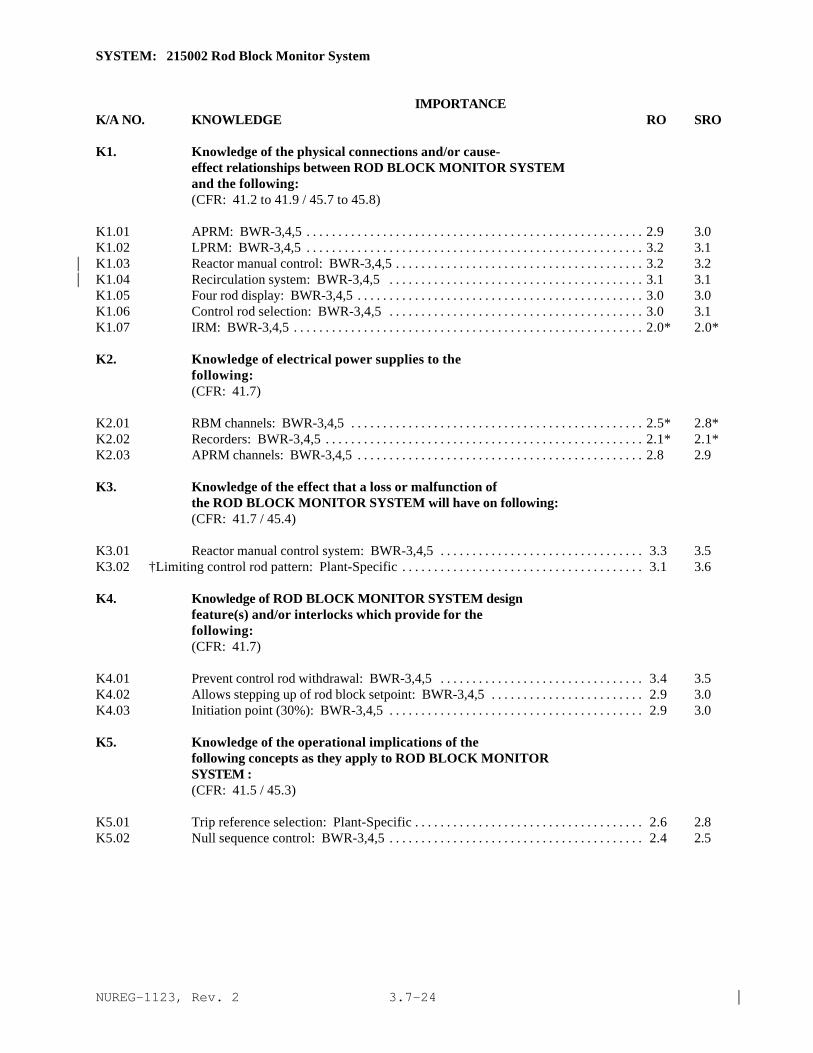
NUREG-1123, Rev. 2 |3.7-24
SYSTEM: 215002 Rod Block Monitor System
IMPORTANCE K/A NO. KNOWLEDGE RO SRO
K1. Knowledge of the physical connections and/or cause-effect relationships between ROD BLOCK MONITOR SYSTEMand the following:(CFR: 41.2 to 41.9 / 45.7 to 45.8)
K1.01 APRM: BWR-3,4,5 . . . . . . . . . . . . . . . . . . . . . . . . . . . . . . . . . . . . . . . . . . . . . . . . . . . . . 2.9 3.0K1.02 LPRM: BWR-3,4,5 . . . . . . . . . . . . . . . . . . . . . . . . . . . . . . . . . . . . . . . . . . . . . . . . . . . . . 3.2 3.1K1.03 Reactor manual control: BWR-3,4,5 . . . . . . . . . . . . . . . . . . . . . . . . . . . . . . . . . . . . . . . 3.2 3.2|K1.04 Recirculation system: BWR-3,4,5 . . . . . . . . . . . . . . . . . . . . . . . . . . . . . . . . . . . . . . . . 3.1 3.1|K1.05 Four rod display: BWR-3,4,5 . . . . . . . . . . . . . . . . . . . . . . . . . . . . . . . . . . . . . . . . . . . . . 3.0 3.0K1.06 Control rod selection: BWR-3,4,5 . . . . . . . . . . . . . . . . . . . . . . . . . . . . . . . . . . . . . . . . 3.0 3.1K1.07 IRM: BWR-3,4,5 . . . . . . . . . . . . . . . . . . . . . . . . . . . . . . . . . . . . . . . . . . . . . . . . . . . . . . . 2.0* 2.0*
K2. Knowledge of electrical power supplies to thefollowing:(CFR: 41.7)
K2.01 RBM channels: BWR-3,4,5 . . . . . . . . . . . . . . . . . . . . . . . . . . . . . . . . . . . . . . . . . . . . . . 2.5* 2.8*K2.02 Recorders: BWR-3,4,5 . . . . . . . . . . . . . . . . . . . . . . . . . . . . . . . . . . . . . . . . . . . . . . . . . . 2.1* 2.1*K2.03 APRM channels: BWR-3,4,5 . . . . . . . . . . . . . . . . . . . . . . . . . . . . . . . . . . . . . . . . . . . . . 2.8 2.9
K3. Knowledge of the effect that a loss or malfunction ofthe ROD BLOCK MONITOR SYSTEM will have on following:(CFR: 41.7 / 45.4)
K3.01 Reactor manual control system: BWR-3,4,5 . . . . . . . . . . . . . . . . . . . . . . . . . . . . . . . . 3.3 3.5K3.02 †Limiting control rod pattern: Plant-Specific . . . . . . . . . . . . . . . . . . . . . . . . . . . . . . . . . . . . . . 3.1 3.6
K4. Knowledge of ROD BLOCK MONITOR SYSTEM designfeature(s) and/or interlocks which provide for thefollowing:(CFR: 41.7)
K4.01 Prevent control rod withdrawal: BWR-3,4,5 . . . . . . . . . . . . . . . . . . . . . . . . . . . . . . . . 3.4 3.5K4.02 Allows stepping up of rod block setpoint: BWR-3,4,5 . . . . . . . . . . . . . . . . . . . . . . . . 2.9 3.0K4.03 Initiation point (30%): BWR-3,4,5 . . . . . . . . . . . . . . . . . . . . . . . . . . . . . . . . . . . . . . . . 2.9 3.0
K5. Knowledge of the operational implications of thefollowing concepts as they apply to ROD BLOCK MONITORSYSTEM :(CFR: 41.5 / 45.3)
K5.01 Trip reference selection: Plant-Specific . . . . . . . . . . . . . . . . . . . . . . . . . . . . . . . . . . . . 2.6 2.8K5.02 Null sequence control: BWR-3,4,5 . . . . . . . . . . . . . . . . . . . . . . . . . . . . . . . . . . . . . . . . 2.4 2.5
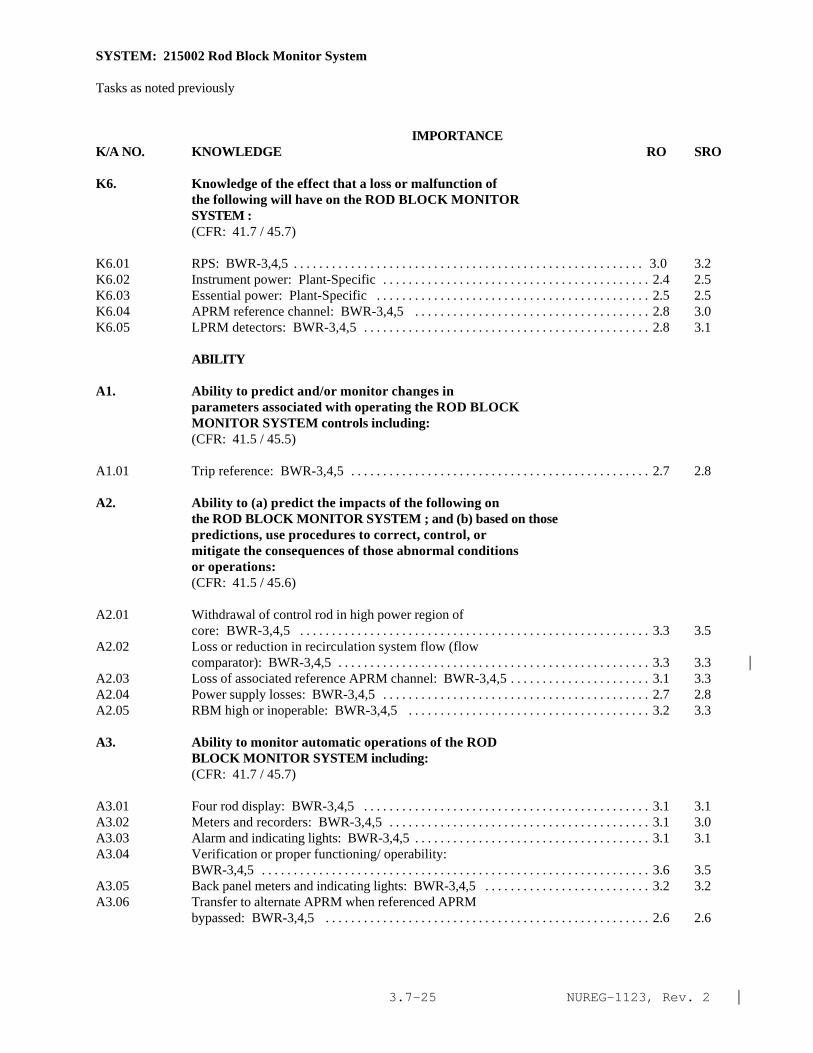
NUREG-1123, Rev. 2 |3.7-25
SYSTEM: 215002 Rod Block Monitor System
Tasks as noted previously
IMPORTANCE K/A NO. KNOWLEDGE RO SRO
K6. Knowledge of the effect that a loss or malfunction ofthe following will have on the ROD BLOCK MONITORSYSTEM :(CFR: 41.7 / 45.7)
K6.01 RPS: BWR-3,4,5 . . . . . . . . . . . . . . . . . . . . . . . . . . . . . . . . . . . . . . . . . . . . . . . . . . . . . . . 3.0 3.2K6.02 Instrument power: Plant-Specific . . . . . . . . . . . . . . . . . . . . . . . . . . . . . . . . . . . . . . . . . . 2.4 2.5K6.03 Essential power: Plant-Specific . . . . . . . . . . . . . . . . . . . . . . . . . . . . . . . . . . . . . . . . . . . 2.5 2.5K6.04 APRM reference channel: BWR-3,4,5 . . . . . . . . . . . . . . . . . . . . . . . . . . . . . . . . . . . . . 2.8 3.0K6.05 LPRM detectors: BWR-3,4,5 . . . . . . . . . . . . . . . . . . . . . . . . . . . . . . . . . . . . . . . . . . . . . 2.8 3.1
ABILITY
A1. Ability to predict and/or monitor changes inparameters associated with operating the ROD BLOCKMONITOR SYSTEM controls including:(CFR: 41.5 / 45.5)
A1.01 Trip reference: BWR-3,4,5 . . . . . . . . . . . . . . . . . . . . . . . . . . . . . . . . . . . . . . . . . . . . . . . 2.7 2.8
A2. Ability to (a) predict the impacts of the following onthe ROD BLOCK MONITOR SYSTEM ; and (b) based on thosepredictions, use procedures to correct, control, ormitigate the consequences of those abnormal conditionsor operations:(CFR: 41.5 / 45.6)
A2.01 Withdrawal of control rod in high power region ofcore: BWR-3,4,5 . . . . . . . . . . . . . . . . . . . . . . . . . . . . . . . . . . . . . . . . . . . . . . . . . . . . . . . 3.3 3.5
A2.02 Loss or reduction in recirculation system flow (flowcomparator): BWR-3,4,5 . . . . . . . . . . . . . . . . . . . . . . . . . . . . . . . . . . . . . . . . . . . . . . . . . 3.3 3.3 |
A2.03 Loss of associated reference APRM channel: BWR-3,4,5 . . . . . . . . . . . . . . . . . . . . . . 3.1 3.3A2.04 Power supply losses: BWR-3,4,5 . . . . . . . . . . . . . . . . . . . . . . . . . . . . . . . . . . . . . . . . . . 2.7 2.8A2.05 RBM high or inoperable: BWR-3,4,5 . . . . . . . . . . . . . . . . . . . . . . . . . . . . . . . . . . . . . . 3.2 3.3
A3. Ability to monitor automatic operations of the RODBLOCK MONITOR SYSTEM including:(CFR: 41.7 / 45.7)
A3.01 Four rod display: BWR-3,4,5 . . . . . . . . . . . . . . . . . . . . . . . . . . . . . . . . . . . . . . . . . . . . . 3.1 3.1A3.02 Meters and recorders: BWR-3,4,5 . . . . . . . . . . . . . . . . . . . . . . . . . . . . . . . . . . . . . . . . . 3.1 3.0A3.03 Alarm and indicating lights: BWR-3,4,5 . . . . . . . . . . . . . . . . . . . . . . . . . . . . . . . . . . . . . 3.1 3.1A3.04 Verification or proper functioning/ operability:
BWR-3,4,5 . . . . . . . . . . . . . . . . . . . . . . . . . . . . . . . . . . . . . . . . . . . . . . . . . . . . . . . . . . . . . 3.6 3.5A3.05 Back panel meters and indicating lights: BWR-3,4,5 . . . . . . . . . . . . . . . . . . . . . . . . . . 3.2 3.2A3.06 Transfer to alternate APRM when referenced APRM
bypassed: BWR-3,4,5 . . . . . . . . . . . . . . . . . . . . . . . . . . . . . . . . . . . . . . . . . . . . . . . . . . . 2.6 2.6

NUREG-1123, Rev. 2 |3.7-26
SYSTEM: 215002 Rod Block Monitor System
Tasks as noted previously
IMPORTANCE K/A NO. ABILITY RO SRO
A4. Ability to manually operate and/or monitor in thecontrol room:(CFR: 41.7 / 45.5 to 45.8)
A4.01 IRM/RBM recorder/switch: BWR-3,4,5 . . . . . . . . . . . . . . . . . . . . . . . . . . . . . . . . . . . . 2.8 2.7A4.02 RBM back panel switches, meters and indicating lights:
BWR-3,4,5 . . . . . . . . . . . . . . . . . . . . . . . . . . . . . . . . . . . . . . . . . . . . . . . . . . . . . . . . . . . . . 2.9 2.9A4.03 Trip bypasses: BWR-3,4,5 . . . . . . . . . . . . . . . . . . . . . . . . . . . . . . . . . . . . . . . . . . . . . . . . 2.8 2.8A4.04 "Push to Check" pushbutton: Plant-Specific . . . . . . . . . . . . . . . . . . . . . . . . . . . . . . . . . 2.6 2.5A4.05 "Setup" pushbutton: Plant-Specific . . . . . . . . . . . . . . . . . . . . . . . . . . . . . . . . . . . . . . . . 2.5 2.5A4.06 Surveillance testing: BWR-3,4,5 . . . . . . . . . . . . . . . . . . . . . . . . . . . . . . . . . . . . . . . . . . 2.7* 2.7

NUREG-1123, Rev. 2 |3.7-27
SYSTEM: 201005 Rod Control and Information System (RCIS)
Tasks as noted previouslyIMPORTANCE
K/A NO. KNOWLEDGE RO SRO
K1. Knowledge of the physical connections and/or cause-effect relationships between ROD CONTROL ANDINFORMATION SYSTEM (RCIS) and the following:(CFR: 41.2 to 41.9 / 45.7 to 45.8)
K1.01 Neutron monitoring system: BWR-6 . . . . . . . . . . . . . . . . . . . . . . . . . . . . . . . . . . . . . . . 3.3 3.3K1.02 Reactor/turbine pressure control system: BWR-6 . . . . . . . . . . . . . . . . . . . . . . . . . . . . 3.3 3.5K1.03 Control rod drive system: BWR-6 . . . . . . . . . . . . . . . . . . . . . . . . . . . . . . . . . . . . . . . . . 3.7 3.7K1.04 Rod position information system: BWR-6 . . . . . . . . . . . . . . . . . . . . . . . . . . . . . . . . . . 3.7 3.7K1.05 Rod action control system: BWR-6 . . . . . . . . . . . . . . . . . . . . . . . . . . . . . . . . . . . . . . . . 3.5 3.5K1.06 Rod gang drive system: BWR-6 . . . . . . . . . . . . . . . . . . . . . . . . . . . . . . . . . . . . . . . . . . . 3.3 3.3K1.07 Rod interface system: BWR-6 . . . . . . . . . . . . . . . . . . . . . . . . . . . . . . . . . . . . . . . . . . . . 3.3 3.3
K2. Knowledge of electrical power supplies to thefollowing:(CFR: 41.7)
K2.01 A.C. electrical power: BWR-6 . . . . . . . . . . . . . . . . . . . . . . . . . . . . . . . . . . . . . . . . . . . . 2.4 2.6
K3. Knowledge of the effect that a loss or malfunction ofthe ROD CONTROL AND INFORMATION SYSTEM (RCIS) willhave on following:(CFR: 41.7 / 45.4)
K3.01 Control rod drive system: BWR-6 . . . . . . . . . . . . . . . . . . . . . . . . . . . . . . . . . . . . . . . . . 3.3 3.7K3.02 Reactor startup: BWR-6 . . . . . . . . . . . . . . . . . . . . . . . . . . . . . . . . . . . . . . . . . . . . . . . . . 3.5 3.5K3.03 Reactor shutdown: BWR-6 . . . . . . . . . . . . . . . . . . . . . . . . . . . . . . . . . . . . . . . . . . . . . . . 3.0 3.2K3.04 †FlUX shaping: BWR-6 . . . . . . . . . . . . . . . . . . . . . . . . . . . . . . . . . . . . . . . . . . . . . . . . . . 3.0 3.3

NUREG-1123, Rev. 2 |3.7-28
SYSTEM: 201005 Rod Control and Information System (RCIS)
Tasks as noted previously
IMPORTANCE K/A NO. KNOWLEDGE RO SRO
K4. Knowledge of ROD CONTROL AND INFORMATION SYSTEM (RCIS)design feature(s) and/or interlocks which provide forthe following:(CFR: 41.7)
K4.01 Limiting the effects of a control Rod accident: BWR-6. . . . . . . . . . . . . . . . . . . . . . . . . . . . . . . . . . . . . . . . . . . . . . . . . . . . . . . . . . . . . . . . . . . . . . 3.2 3.2
K4.02 Bank position withdrawal sequence (BPWS): BWR-6 . . . . . . . . . . . . . . . . . . . . . . . . 3.3 3.3K4.03 Rod withdrawal block signals: BWR-6 . . . . . . . . . . . . . . . . . . . . . . . . . . . . . . . . . . . . . 3.5 3.5K4.04 Rod insertion block signals: BWR-6 . . . . . . . . . . . . . . . . . . . . . . . . . . . . . . . . . . . . . . 3.5 3.5K4.05 Rod withdrawal limiter: BWR-6 . . . . . . . . . . . . . . . . . . . . . . . . . . . . . . . . . . . . . . . . . . 3.5 3.5K4.06 Rod pattern controller rod blocks: BWR-6 . . . . . . . . . . . . . . . . . . . . . . . . . . . . . . . . . 3.5 3.5
K5. Knowledge of the operational implications of thefollowing concepts as they apply to ROD CONTROL ANDINFORMATION SYSTEM (RCIS) :(CFR: 41.5 / 45.3)
K5.01 †Rod pattern and program development: BWR-6 . . . . . . . . . . . . . . . . . . . . . . . . . . . . 2.3 3.2K5.02 Rod pattern controller (RPC): BWR-6 . . . . . . . . . . . . . . . . . . . . . . . . . . . . . . . . . . . . 2.8 3.3K5.03 Rod groups: BWR-6 . . . . . . . . . . . . . . . . . . . . . . . . . . . . . . . . . . . . . . . . . . . . . . . . . . . . 2.3 2.7K5.04 †Rod sequences: BWR-6 . . . . . . . . . . . . . . . . . . . . . . . . . . . . . . . . . . . . . . . . . . . . . . . 2.7 3.0K5.05 Rod density: BWR-6 . . . . . . . . . . . . . . . . . . . . . . . . . . . . . . . . . . . . . . . . . . . . . . . . . . . 2.7 3.0K5.06 Target rod pattern: BWR-6 . . . . . . . . . . . . . . . . . . . . . . . . . . . . . . . . . . . . . . . . . . . . . . 2.8 2.8K5.07 Low power alarm point: BWR-6 . . . . . . . . . . . . . . . . . . . . . . . . . . . . . . . . . . . . . . . . . . 3.5 3.5K5.08 Transition zone: BWR-6 . . . . . . . . . . . . . . . . . . . . . . . . . . . . . . . . . . . . . . . . . . . . . . . . 3.2 3.5K5.09 High power setpoints BWR-6 . . . . . . . . . . . . . . . . . . . . . . . . . . . . . . . . . . . . . . . . . . . . 3.5 3,5K5.10 Rod withdrawal limiter: BWR-6 . . . . . . . . . . . . . . . . . . . . . . . . . . . . . . . . . . . . . . . . . . 3.2 3.3K5.11 Control rod motion: BWR-6 . . . . . . . . . . . . . . . . . . . . . . . . . . . . . . . . . . . . . . . . . . . . . 3.3 3.3K5.12 Command word generation and sequencing (operator follow, scan and test): BWR-6 . . . . . . . . . . . . . . . . . . . . . . . . . . . . . . . . . . . . . . . . . . . 1.8* 2.2*K5.13 Position indication probes: BWR-6 . . . . . . . . . . . . . . . . . . . . . . . . . . . . . . . . . . . . . . . 2.5 2.7
K6. Knowledge of the effect that a loss or malfunction ofthe following will have on the ROD CONTROL ANDINFORMATION SYSTEM (RCIS) :(CFR: 41.7 / 45.7)
K6.01 First stage shell pressure or opening of a bypassvalve(s): BWR-6 . . . . . . . . . . . . . . . . . . . . . . . . . . . . . . . . . . . . . . . . . . . . . . . . . . . . . . . 3.2 3.2
K6.02 Rod position signal: BWR-6 . . . . . . . . . . . . . . . . . . . . . . . . . . . . . . . . . . . . . . . . . . . . . 3.2 3.3K6.03 A.C. electrical power: BWR-6 . . . . . . . . . . . . . . . . . . . . . . . . . . . . . . . . . . . . . . . . . . . 2.5 2.8K6.04 IRM channel: BWR-6 . . . . . . . . . . . . . . . . . . . . . . . . . . . . . . . . . . . . . . . . . . . . . . . . . . 3.0 3.2K6.05 SRM channel: BWR-6 . . . . . . . . . . . . . . . . . . . . . . . . . . . . . . . . . . . . . . . . . . . . . . . . . . 3.0 3.2K6.06 APRM channel: BWR-6 . . . . . . . . . . . . . . . . . . . . . . . . . . . . . . . . . . . . . . . . . . . . . . . . 3.0 3.0
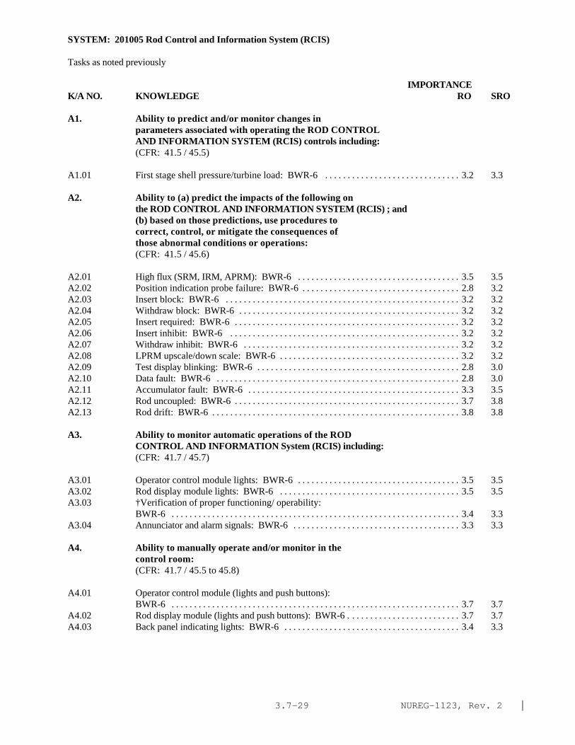
NUREG-1123, Rev. 2 |3.7-29
SYSTEM: 201005 Rod Control and Information System (RCIS)
Tasks as noted previously
IMPORTANCE K/A NO. KNOWLEDGE RO SRO
A1. Ability to predict and/or monitor changes inparameters associated with operating the ROD CONTROLAND INFORMATION SYSTEM (RCIS) controls including:(CFR: 41.5 / 45.5)
A1.01 First stage shell pressure/turbine load: BWR-6 . . . . . . . . . . . . . . . . . . . . . . . . . . . . . . 3.2 3.3
A2. Ability to (a) predict the impacts of the following onthe ROD CONTROL AND INFORMATION SYSTEM (RCIS) ; and(b) based on those predictions, use procedures tocorrect, control, or mitigate the consequences ofthose abnormal conditions or operations:(CFR: 41.5 / 45.6)
A2.01 High flux (SRM, IRM, APRM): BWR-6 . . . . . . . . . . . . . . . . . . . . . . . . . . . . . . . . . . . . 3.5 3.5A2.02 Position indication probe failure: BWR-6 . . . . . . . . . . . . . . . . . . . . . . . . . . . . . . . . . . . 2.8 3.2A2.03 Insert block: BWR-6 . . . . . . . . . . . . . . . . . . . . . . . . . . . . . . . . . . . . . . . . . . . . . . . . . . . . 3.2 3.2A2.04 Withdraw block: BWR-6 . . . . . . . . . . . . . . . . . . . . . . . . . . . . . . . . . . . . . . . . . . . . . . . . . 3.2 3.2A2.05 Insert required: BWR-6 . . . . . . . . . . . . . . . . . . . . . . . . . . . . . . . . . . . . . . . . . . . . . . . . . . 3.2 3.2A2.06 Insert inhibit: BWR-6 . . . . . . . . . . . . . . . . . . . . . . . . . . . . . . . . . . . . . . . . . . . . . . . . . . . 3.2 3.2A2.07 Withdraw inhibit: BWR-6 . . . . . . . . . . . . . . . . . . . . . . . . . . . . . . . . . . . . . . . . . . . . . . . . 3.2 3.2A2.08 LPRM upscale/down scale: BWR-6 . . . . . . . . . . . . . . . . . . . . . . . . . . . . . . . . . . . . . . . . 3.2 3.2A2.09 Test display blinking: BWR-6 . . . . . . . . . . . . . . . . . . . . . . . . . . . . . . . . . . . . . . . . . . . . . 2.8 3.0A2.10 Data fault: BWR-6 . . . . . . . . . . . . . . . . . . . . . . . . . . . . . . . . . . . . . . . . . . . . . . . . . . . . . . 2.8 3.0A2.11 Accumulator fault: BWR-6 . . . . . . . . . . . . . . . . . . . . . . . . . . . . . . . . . . . . . . . . . . . . . . . 3.3 3.5A2.12 Rod uncoupled: BWR-6 . . . . . . . . . . . . . . . . . . . . . . . . . . . . . . . . . . . . . . . . . . . . . . . . . . 3.7 3.8A2.13 Rod drift: BWR-6 . . . . . . . . . . . . . . . . . . . . . . . . . . . . . . . . . . . . . . . . . . . . . . . . . . . . . . . 3.8 3.8
A3. Ability to monitor automatic operations of the RODCONTROL AND INFORMATION System (RCIS) including:(CFR: 41.7 / 45.7)
A3.01 Operator control module lights: BWR-6 . . . . . . . . . . . . . . . . . . . . . . . . . . . . . . . . . . . . 3.5 3.5A3.02 Rod display module lights: BWR-6 . . . . . . . . . . . . . . . . . . . . . . . . . . . . . . . . . . . . . . . . 3.5 3.5A3.03 †Verification of proper functioning/ operability:
BWR-6 . . . . . . . . . . . . . . . . . . . . . . . . . . . . . . . . . . . . . . . . . . . . . . . . . . . . . . . . . . . . . . . . 3.4 3.3A3.04 Annunciator and alarm signals: BWR-6 . . . . . . . . . . . . . . . . . . . . . . . . . . . . . . . . . . . . . 3.3 3.3
A4. Ability to manually operate and/or monitor in thecontrol room:(CFR: 41.7 / 45.5 to 45.8)
A4.01 Operator control module (lights and push buttons):BWR-6 . . . . . . . . . . . . . . . . . . . . . . . . . . . . . . . . . . . . . . . . . . . . . . . . . . . . . . . . . . . . . . . . 3.7 3.7
A4.02 Rod display module (lights and push buttons): BWR-6 . . . . . . . . . . . . . . . . . . . . . . . . . 3.7 3.7A4.03 Back panel indicating lights: BWR-6 . . . . . . . . . . . . . . . . . . . . . . . . . . . . . . . . . . . . . . . 3.4 3.3

NUREG-1123, Rev. 2 |3.7-30
SYSTEM: 214000 Rod Position Information System
TASK: Startup the rod position indication system Perform a position indication alignment during a reactor startup Monitor the rod position indication system Shutdown the rod position indication system (RPIS)
IMPORTANCE K/A NO. KNOWLEDGE RO SRO
K1. Knowledge of the physical connections and/or cause-effect relationships between ROD POSITION INFORMATIONSYSTEM and the following:(CFR: 41.2 to 41.9 / 45.7 to 45.8)
K1.01 RWM: Plant-Specific . . . . . . . . . . . . . . . . . . . . . . . . . . . . . . . . . . . . . . . . . . . . . . . . . . . 3.0 3.2K1.02 RSCS: Plant-Specific . . . . . . . . . . . . . . . . . . . . . . . . . . . . . . . . . . . . . . . . . . . . . . . . . . . 2.9 3.1K1.03 CRDM . . . . . . . . . . . . . . . . . . . . . . . . . . . . . . . . . . . . . . . . . . . . . . . . . . . . . . . . . . . . . . . . 3.0 3.1K1.04 RMCS: Plant-Specific . . . . . . . . . . . . . . . . . . . . . . . . . . . . . . . . . . . . . . . . . . . . . . . . . . 3.2 3.2K1.05 Full core display: Plant-Specific . . . . . . . . . . . . . . . . . . . . . . . . . . . . . . . . . . . . . . . . . . 3.3 3.3K1.06 RCIS: Plant-Specific . . . . . . . . . . . . . . . . . . . . . . . . . . . . . . . . . . . . . . . . . . . . . . . . . . . . 3.4 3.4K1.07 Process computer . . . . . . . . . . . . . . . . . . . . . . . . . . . . . . . . . . . . . . . . . . . . . . . . . . . . . . . 2.7 3.0K1.08 CRIDS/ERIS/SPDS/GDS: Plant-Specific . . . . . . . . . . . . . . . . . . . . . . . . . . . . . . . . . . . 2.4 2.6
K2. Knowledge of electrical power supplies to thefollowing:(CFR: 41.7)
None|
K3. Knowledge of the effect that a loss or malfunction ofthe ROD POSITION INFORMATION SYSTEM will have onfollowing:(CFR: 41.7 / 45.4)
K3.01 RWM: Plant-Specific . . . . . . . . . . . . . . . . . . . . . . . . . . . . . . . . . . . . . . . . . . . . . . . . . . . 3.0 3.2K3.02 RSCS: Plant-Specific . . . . . . . . . . . . . . . . . . . . . . . . . . . . . . . . . . . . . . . . . . . . . . . . . . . 3.0 3.1K3.03 RMCS: Plant-Specific . . . . . . . . . . . . . . . . . . . . . . . . . . . . . . . . . . . . . . . . . . . . . . . . . . 3.1 3.2K3.04 RCIS: Plant-Specific . . . . . . . . . . . . . . . . . . . . . . . . . . . . . . . . . . . . . . . . . . . . . . . . . . . . 3.3 3.3K3.05 Process computer . . . . . . . . . . . . . . . . . . . . . . . . . . . . . . . . . . . . . . . . . . . . . . . . . . . . . . . 2.3 2.6K3.06 CRIDS/ERIS/SPDS/GDS: Plant-Specific . . . . . . . . . . . . . . . . . . . . . . . . . . . . . . . . . . . 2.3* 2.5
K4. Knowledge of ROD POSITION INFORMATION SYSTEM designfeature(s) and/or interlocks which provide for thefollowing:(CFR: 41.7)
K4.01 Reed switch locations . . . . . . . . . . . . . . . . . . . . . . . . . . . . . . . . . . . . . . . . . . . . . . . . . . . 3.0 3.1K4.02 Thermocouple . . . . . . . . . . . . . . . . . . . . . . . . . . . . . . . . . . . . . . . . . . . . . . . . . . . . . . . . . . 2.5* 2.5
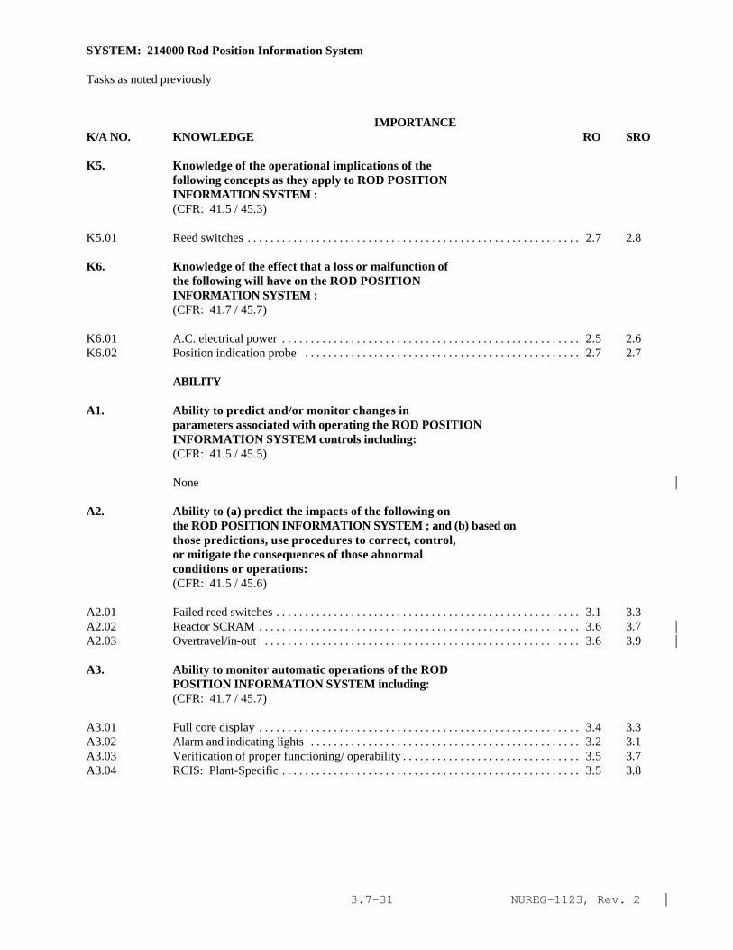
NUREG-1123, Rev. 2 |3.7-31
SYSTEM: 214000 Rod Position Information System
Tasks as noted previously
IMPORTANCE K/A NO. KNOWLEDGE RO SRO
K5. Knowledge of the operational implications of thefollowing concepts as they apply to ROD POSITIONINFORMATION SYSTEM :(CFR: 41.5 / 45.3)
K5.01 Reed switches . . . . . . . . . . . . . . . . . . . . . . . . . . . . . . . . . . . . . . . . . . . . . . . . . . . . . . . . . . 2.7 2.8
K6. Knowledge of the effect that a loss or malfunction ofthe following will have on the ROD POSITIONINFORMATION SYSTEM :(CFR: 41.7 / 45.7)
K6.01 A.C. electrical power . . . . . . . . . . . . . . . . . . . . . . . . . . . . . . . . . . . . . . . . . . . . . . . . . . . . 2.5 2.6K6.02 Position indication probe . . . . . . . . . . . . . . . . . . . . . . . . . . . . . . . . . . . . . . . . . . . . . . . . 2.7 2.7
ABILITY
A1. Ability to predict and/or monitor changes inparameters associated with operating the ROD POSITIONINFORMATION SYSTEM controls including:(CFR: 41.5 / 45.5)
None |
A2. Ability to (a) predict the impacts of the following onthe ROD POSITION INFORMATION SYSTEM ; and (b) based onthose predictions, use procedures to correct, control,or mitigate the consequences of those abnormalconditions or operations:(CFR: 41.5 / 45.6)
A2.01 Failed reed switches . . . . . . . . . . . . . . . . . . . . . . . . . . . . . . . . . . . . . . . . . . . . . . . . . . . . . 3.1 3.3A2.02 Reactor SCRAM . . . . . . . . . . . . . . . . . . . . . . . . . . . . . . . . . . . . . . . . . . . . . . . . . . . . . . . . 3.6 3.7 |A2.03 Overtravel/in-out . . . . . . . . . . . . . . . . . . . . . . . . . . . . . . . . . . . . . . . . . . . . . . . . . . . . . . . 3.6 3.9 |
A3. Ability to monitor automatic operations of the RODPOSITION INFORMATION SYSTEM including:(CFR: 41.7 / 45.7)
A3.01 Full core display . . . . . . . . . . . . . . . . . . . . . . . . . . . . . . . . . . . . . . . . . . . . . . . . . . . . . . . . 3.4 3.3A3.02 Alarm and indicating lights . . . . . . . . . . . . . . . . . . . . . . . . . . . . . . . . . . . . . . . . . . . . . . . 3.2 3.1A3.03 Verification of proper functioning/ operability . . . . . . . . . . . . . . . . . . . . . . . . . . . . . . . 3.5 3.7A3.04 RCIS: Plant-Specific . . . . . . . . . . . . . . . . . . . . . . . . . . . . . . . . . . . . . . . . . . . . . . . . . . . . 3.5 3.8

NUREG-1123, Rev. 2 |3.7-32
SYSTEM: 214000 Rod Position Information System
Tasks as noted previously
IMPORTANCE K/A NO. KNOWLEDGE RO SRO
A4. Ability to manually operate and/or monitor in thecontrol room:(CFR: 41.7 / 45.5 to 45.8)
A4.01 RCIS rod action control bypass switches . . . . . . . . . . . . . . . . . . . . . . . . . . . . . . . . . . . . 3.2 3.3A4.02 Control rod position . . . . . . . . . . . . . . . . . . . . . . . . . . . . . . . . . . . . . . . . . . . . . . . . . . . . . 3.8* 3.8*A4.03 Control rod drive temperature . . . . . . . . . . . . . . . . . . . . . . . . . . . . . . . . . . . . . . . . . . . . . 2.8 2.7

NUREG-1123, Rev. 2 |3.7-33
SYSTEM: 201004 Rod Sequence Control System (Plant Specific)
TASK: Conduct rod sequence control functional test
IMPORTANCE K/A NO. KNOWLEDGE RO SRO
K1. Knowledge of the physical connections and/or cause-effect relationships between ROD SEQUENCE CONTROLSYSTEM (PLANT SPECIFIC) and the following:(CFR: 41.2 to 41.9 / 45.7 to 45.8)
K1.01 Reactor manual control system: BWR-4,5 . . . . . . . . . . . . . . . . . . . . . . . . . . . . . . . . . . 3.2 3.3K1.02 Turbine generator system: BWR-4,5 . . . . . . . . . . . . . . . . . . . . . . . . . . . . . . . . . . . . . . . 3.1 3.1K1.03 Rod position information system: BWR-4,5 . . . . . . . . . . . . . . . . . . . . . . . . . . . . . . . . . 3.1 3.1K1.04 Rod worth minimizer: BWR-4,5 . . . . . . . . . . . . . . . . . . . . . . . . . . . . . . . . . . . . . . . . . . . 2.8 3.0
K2. Knowledge of electrical power supplies to thefollowing:(CFR: 41.7)
None |
K3. Knowledge of the effect that a loss or malfunction ofthe ROD SEQUENCE CONTROL SYSTEM (PLANT SPECIFIC) willhave on following:(CFR: 41.7 / 45.4)
K3.01 Reactor manual control: BWR-4,5 . . . . . . . . . . . . . . . . . . . . . . . . . . . . . . . . . . . . . . . . . 3.3 3.4
K4. Knowledge of ROD SEQUENCE CONTROL SYSTEM (PLANTSPECIFIC) design feature(s) and/or interlocks whichprovide for the following:(CFR: 41.7)
K4.01 Select blocks: BWR-4,5 . . . . . . . . . . . . . . . . . . . . . . . . . . . . . . . . . . . . . . . . . . . . . . . . . 3.0 3.1K4.02 Insert rod blocks: BWR-4,5 . . . . . . . . . . . . . . . . . . . . . . . . . . . . . . . . . . . . . . . . . . . . . . 3.1 3.2K4.03 Withdraw rod blocks: BWR-4,5 . . . . . . . . . . . . . . . . . . . . . . . . . . . . . . . . . . . . . . . . . . . 3.3 3.4K4.04 RSCS bypass as reactor power increases: BWR-4,5 . . . . . . . . . . . . . . . . . . . . . . . . . . 3.3 3.3K4.05 Rod movement, direction, and selection information:
BWR-4,5 . . . . . . . . . . . . . . . . . . . . . . . . . . . . . . . . . . . . . . . . . . . . . . . . . . . . . . . . . . . . . . 3.2 3.2K4.06 Group notch control: BWR-4,5 . . . . . . . . . . . . . . . . . . . . . . . . . . . . . . . . . . . . . . . . . . . 3.3 3.4K4.07 Minimizing rod worth: BWR-4,5 . . . . . . . . . . . . . . . . . . . . . . . . . . . . . . . . . . . . . . . . . . 3.6 3.7
K5. Knowledge of the operational implications of thefollowing concepts as they apply to ROD SEQUENCE(CFR: 41.5 / 45.3)
CONTROL SYSTEM (PLANT SPECIFIC) :
K5.01 Prevention of clad damage if a control rod dropaccident (CRDA) occurs: BWR-4,5 . . . . . . . . . . . . . . . . . . . . . . . . . . . . . . . . . . . . . . . . 3.6 4.0
K5.02 Sequences and groups: BWR-4,5 . . . . . . . . . . . . . . . . . . . . . . . . . . . . . . . . . . . . . . . . . . 3.1 3.3K5.03 Group notch control limits and rod density: BWR-4,5 . . . . . . . . . . . . . . . . . . . . . . . . . 3.3 3.5
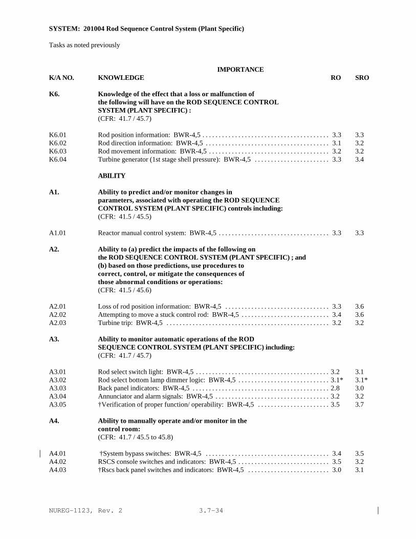
NUREG-1123, Rev. 2 |3.7-34
SYSTEM: 201004 Rod Sequence Control System (Plant Specific)
Tasks as noted previously
IMPORTANCE K/A NO. KNOWLEDGE RO SRO
K6. Knowledge of the effect that a loss or malfunction ofthe following will have on the ROD SEQUENCE CONTROLSYSTEM (PLANT SPECIFIC) :(CFR: 41.7 / 45.7)
K6.01 Rod position information: BWR-4,5 . . . . . . . . . . . . . . . . . . . . . . . . . . . . . . . . . . . . . . . 3.3 3.3K6.02 Rod direction information: BWR-4,5 . . . . . . . . . . . . . . . . . . . . . . . . . . . . . . . . . . . . . . 3.1 3.2K6.03 Rod movement information: BWR-4,5 . . . . . . . . . . . . . . . . . . . . . . . . . . . . . . . . . . . . . 3.2 3.2K6.04 Turbine generator (1st stage shell pressure): BWR-4,5 . . . . . . . . . . . . . . . . . . . . . . . 3.3 3.4
ABILITY
A1. Ability to predict and/or monitor changes inparameters, associated with operating the ROD SEQUENCECONTROL SYSTEM (PLANT SPECIFIC) controls including:(CFR: 41.5 / 45.5)
A1.01 Reactor manual control system: BWR-4,5 . . . . . . . . . . . . . . . . . . . . . . . . . . . . . . . . . . 3.3 3.3
A2. Ability to (a) predict the impacts of the following onthe ROD SEQUENCE CONTROL SYSTEM (PLANT SPECIFIC) ; and(b) based on those predictions, use procedures tocorrect, control, or mitigate the consequences ofthose abnormal conditions or operations:(CFR: 41.5 / 45.6)
A2.01 Loss of rod position information: BWR-4,5 . . . . . . . . . . . . . . . . . . . . . . . . . . . . . . . . 3.3 3.6A2.02 Attempting to move a stuck control rod: BWR-4,5 . . . . . . . . . . . . . . . . . . . . . . . . . . . 3.4 3.6A2.03 Turbine trip: BWR-4,5 . . . . . . . . . . . . . . . . . . . . . . . . . . . . . . . . . . . . . . . . . . . . . . . . . . 3.2 3.2
A3. Ability to monitor automatic operations of the RODSEQUENCE CONTROL SYSTEM (PLANT SPECIFIC) including:(CFR: 41.7 / 45.7)
A3.01 Rod select switch light: BWR-4,5 . . . . . . . . . . . . . . . . . . . . . . . . . . . . . . . . . . . . . . . . . 3.2 3.1A3.02 Rod select bottom lamp dimmer logic: BWR-4,5 . . . . . . . . . . . . . . . . . . . . . . . . . . . . 3.1* 3.1*A3.03 Back panel indicators: BWR-4,5 . . . . . . . . . . . . . . . . . . . . . . . . . . . . . . . . . . . . . . . . . . 2.8 3.0A3.04 Annunciator and alarm signals: BWR-4,5 . . . . . . . . . . . . . . . . . . . . . . . . . . . . . . . . . . . 3.2 3.2A3.05 †Verification of proper function/ operability: BWR-4,5 . . . . . . . . . . . . . . . . . . . . . . 3.5 3.7
A4. Ability to manually operate and/or monitor in thecontrol room:(CFR: 41.7 / 45.5 to 45.8)
A4.01 †System bypass switches: BWR-4,5 . . . . . . . . . . . . . . . . . . . . . . . . . . . . . . . . . . . . . . 3.4 3.5|A4.02 RSCS console switches and indicators: BWR-4,5 . . . . . . . . . . . . . . . . . . . . . . . . . . . . 3.5 3.2A4.03 †Rscs back panel switches and indicators: BWR-4,5 . . . . . . . . . . . . . . . . . . . . . . . . . 3.0 3.1

NUREG-1123, Rev. 2 |3.7-35
SYSTEM: 201006 Rod Worth Minimizer System (RWM) (Plant Specific)
TASK: Conduct rod worth minimizer functional test
IMPORTANCE K/A NO. KNOWLEDGE RO SRO
K1. Knowledge of the physical connections and/or cause-effect relationships between ROD WORTH MINIMIZERSYSTEM (RWM) (PLANT SPECIFIC) and the following:(CFR: 41.2 to 41.9 / 45.7 to 45.8)
K1.01 Reactor manual control: P-Spec(Not-BWR6) . . . . . . . . . . . . . . . . . . . . . . . . . . . . . . 3.4 3.4K1.02 Rod position indication system: P-Spec(Not-BWR6) . . . . . . . . . . . . . . . . . . . . . . . . 3.4 3.4K1.03 Reactor water level control (feed flow): P-Spec(Not-
BWR6) . . . . . . . . . . . . . . . . . . . . . . . . . . . . . . . . . . . . . . . . . . . . . . . . . . . . . . . . . . . . . . . 3.1 3.2K1.04 Steam flow/reactor power: P-Spec(Not-BWR6) . . . . . . . . . . . . . . . . . . . . . . . . . . . . 3.1 3.2K1.05 Control rod drop accident: P-Spec(Not-BWR6) . . . . . . . . . . . . . . . . . . . . . . . . . . . . 3.5 3.8K1.06 Rod sequence control system: P-Spec(Not-BWR6) . . . . . . . . . . . . . . . . . . . . . . . . . 3.3 3.4K1.07 Process computer: P-Spec(Not-BWR6) . . . . . . . . . . . . . . . . . . . . . . . . . . . . . . . . . . . 2.8 2.9K1.08 Reactor power (turbine first stage pressure): P-
Spec(Not-BWR6) . . . . . . . . . . . . . . . . . . . . . . . . . . . . . . . . . . . . . . . . . . . . . . . . . . . . . . 3.2 3.3
K2. Knowledge of electrical power supplies to thefollowing:(CFR: 41.7)
K2.01 Rod worth minimizer: P-Spec(Not-BWR6) . . . . . . . . . . . . . . . . . . . . . . . . . . . . . . . . 2.2* 2.5*
K3. Knowledge of the effect that a loss or malfunction ofthe ROD WORTH MINIMIZER SYSTEM (RWM) (PLANT SPECIFIC)will have on following:(CFR: 41.7 / 45.4)
K3.01 Reactor manual control system: P-Spec(Not-BWR6) . . . . . . . . . . . . . . . . . . . . . . . . 3.2 3.5
K4. Knowledge of ROD WORTH MINIMIZER SYSTEM (RWM) (PLANTSPECIFIC) design feature(s) and/or interlocks whichprovide for the following:(CFR: 41.7)
K4.01 Insert blocks/errors: P-Spec(Not-BWR6) . . . . . . . . . . . . . . . . . . . . . . . . . . . . . . . . . . 3.4 3.5K4.02 Withdraw blocks/errors: P-Spec(Not-BWR6) . . . . . . . . . . . . . . . . . . . . . . . . . . . . . . 3.5 3.5K4.03 Select blocks/errors: P-Spec(Not-BWR6) . . . . . . . . . . . . . . . . . . . . . . . . . . . . . . . . . 3.3 3.4K4.04 System bypass: P-Spec(Not-BWR6) . . . . . . . . . . . . . . . . . . . . . . . . . . . . . . . . . . . . . . 3.4 3.5K4.05 Substitute rod position data: P-Spec(Not-BWR6) . . . . . . . . . . . . . . . . . . . . . . . . . . . 2.8 3.0K4.06 Correction of out of sequence rod positions: P-
Spec(Not-BWR6) . . . . . . . . . . . . . . . . . . . . . . . . . . . . . . . . . . . . . . . . . . . . . . . . . . . . . . 3.2 3.4K4.07 Display of out of position control rods without rod
blocks (transition zone): P-Spec(Not-BWR6) . . . . . . . . . . . . . . . . . . . . . . . . . . . . . . 3.1 3.2K4.08 System testing: P-Spec(Not-BWR6) . . . . . . . . . . . . . . . . . . . . . . . . . . . . . . . . . . . . . . 2.8 2.8K4.09 System initialization: P-Spec(Not-BWR6) . . . . . . . . . . . . . . . . . . . . . . . . . . . . . . . . . 3.2 3.2

NUREG-1123, Rev. 2 |3.7-36
SYSTEM: 201006 Rod Worth Minimizer System (RWM) (Plant Specific)
Tasks as noted previously
IMPORTANCE K/A NO. KNOWLEDGE RO SRO
K5. Knowledge of the operational implications of thefollowing concepts as they apply to ROD WORTHMINIMIZER SYSTEM (RWM) (PLANT SPECIFIC) :(CFR: 41.5 / 45.3)
K5.01 Minimize clad damage if a control rod drop accident(CRDA) occurs: P-Spec(Not-BWR6) . . . . . . . . . . . . . . . . . . . . . . . . . . . . . . . . . . . . . . 3.3 3.7
K5.02 Low power set point: P-Spec(Not-BWR6) . . . . . . . . . . . . . . . . . . . . . . . . . . . . . . . . . . 2.9 3.0K5.03 Low power alarm point (LPAP): P-Spec(Not-BWR6) . . . . . . . . . . . . . . . . . . . . . . . . . 2.8 2.9K5.04 Transition zone: P-Spec(Not-BWR6) . . . . . . . . . . . . . . . . . . . . . . . . . . . . . . . . . . . . . . 2.8 2.8K5.05 High power set point: P-Spec(Not-BWR6) . . . . . . . . . . . . . . . . . . . . . . . . . . . . . . . . . . 2.9 3.0K5.06 Rod groups and steps: P-Spec(Not-BWR6) . . . . . . . . . . . . . . . . . . . . . . . . . . . . . . . . . 2.8 3.0K5.07 Latch groups: P-Spec(Not-BWR6) . . . . . . . . . . . . . . . . . . . . . . . . . . . . . . . . . . . . . . . . 2.8 2.9K5.08 Operating sequence: P-Spec(Not-BWR6) . . . . . . . . . . . . . . . . . . . . . . . . . . . . . . . . . . . 2.9 2.9K5.09 Select error: P-Spec(Not-BWR6) . . . . . . . . . . . . . . . . . . . . . . . . . . . . . . . . . . . . . . . . . 3.2 3.2K5.10 Withdraw error: P-Spec(Not-BWR6) . . . . . . . . . . . . . . . . . . . . . . . . . . . . . . . . . . . . . . 3.2 3.3K5.11 Insert error: P-Spec(Not-BWR6) . . . . . . . . . . . . . . . . . . . . . . . . . . . . . . . . . . . . . . . . . . 3.2 3.3K5.12 Withdraw block: P-Spec(Not-BWR6) . . . . . . . . . . . . . . . . . . . . . . . . . . . . . . . . . . . . . . 3.5 3.5K5.13 Insert block: P-Spec(Not-BWR6) . . . . . . . . . . . . . . . . . . . . . . . . . . . . . . . . . . . . . . . . . 3.5 3.5K5.14 Alternate withdraw and insert limits: P-Spec(Not-
BWR6) . . . . . . . . . . . . . . . . . . . . . . . . . . . . . . . . . . . . . . . . . . . . . . . . . . . . . . . . . . . . . . . . 3.0 3.0
K6. Knowledge of the effect that a loss or malfunction ofthe following will have on the ROD WORTH MINIMIZERSYSTEM (RWM) (PLANT SPECIFIC) :(CFR: 41.7 / 45.7)
K6.01 RWM power supply: P-Spec(Not-BWR6) . . . . . . . . . . . . . . . . . . . . . . . . . . . . . . . . . . 2.8 3.2K6.02 Reactor water level control input: P-Spec(Not-BWR6) . . . . . . . . . . . . . . . . . . . . . . . . 2.9 2.9K6.03 Rod position indication: P-Spec(Not-BWR6) . . . . . . . . . . . . . . . . . . . . . . . . . . . . . . . 2.9 2.9K6.04 Process computer: P-Spec(Not-BWR6) . . . . . . . . . . . . . . . . . . . . . . . . . . . . . . . . . . . . 2.7 2.8K6.05 Steam flow input: P-Spec(Not-BWR6) . . . . . . . . . . . . . . . . . . . . . . . . . . . . . . . . . . . . . 2.7 2.7
ABILITY
A1. Ability to predict and/or monitor changes inparameters associated with operating the ROD WORTHMINIMIZER SYSTEM (RWM) (PLANT SPECIFIC) controlsincluding:(CFR: 41.5 / 45.5)
A1.01 Rod position: P-Spec(Not-BWR6) . . . . . . . . . . . . . . . . . . . . . . . . . . . . . . . . . . . . . . . . 3.2 3.3A1.02 Status of control rod movement blocks; P-Spec(Not-
BWR6) . . . . . . . . . . . . . . . . . . . . . . . . . . . . . . . . . . . . . . . . . . . . . . . . . . . . . . . . . . . . . . . . 3.4 3.5A1.03 Latched group indication: P-Spec(Not-BWR6) . . . . . . . . . . . . . . . . . . . . . . . . . . . . . . 2.9 3.0

NUREG-1123, Rev. 2 |3.7-37
SYSTEM; 201006 Rod Worth Minimizer System (RWM) (Plant Specific)
Tasks as noted previously
IMPORTANCE K/A NO. KNOWLEDGE RO SRO
A2. Ability to (a) predict the impacts of the following onthe ROD WORTH MINIMIZER SYSTEM (RWH) (PLANT SPECIFIC); and (b) based on those predictions, use proceduresto correct, control, or mitigate the consequences ofthose abnormal conditions or operations:(CFR: 41.5 / 45.6)
A2.01 Power supply loss: P-Spec(Not-BWR6) . . . . . . . . . . . . . . . . . . . . . . . . . . . . . . . . . . . . 2.5 2.8A2.02 Loss of steam flow input: P-Spec(Not-BWR6) . . . . . . . . . . . . . . . . . . . . . . . . . . . . . . . 2.6 2.9A2.03 Rod drift: P-Spec(Not-BWR6) . . . . . . . . . . . . . . . . . . . . . . . . . . . . . . . . . . . . . . . . . . . . 3.0 3.2A2.04 Stuck rod: P-Spec(Not-BWR6) . . . . . . . . . . . . . . . . . . . . . . . . . . . . . . . . . . . . . . . . . . . . 3.0 3.3A2.05 Out of sequence rod movement; P-Spec(Not-BWR6) . . . . . . . . . . . . . . . . . . . . . . . . . . 3.1 3.5A2.06 Loss of reactor water level control input: P-
Spec(Not-BWR6) . . . . . . . . . . . . . . . . . . . . . . . . . . . . . . . . . . . . . . . . . . . . . . . . . . . . . . . . 2.9 3.3A2.07 RWM hardware/software failure: P-Spec(Not-BWR6) . . . . . . . . . . . . . . . . . . . . . . . . 2.5 2.8
A3. Ability to monitor automatic operations of the RODWORTH MINIMIZER SYSTEM (RWM) (PLANT SPECIFIC)including:(CFR: 41.7 / 45.7)
A3.01 System window and light indication: P-Spec(Not-BWR6). . . . . . . . . . . . . . . . . . . . . . 3.2 3.1A3.02 Verification of proper functioning/ operability: Plant- Spec(Not-BWR6) . . . . . . . . . . . . . . . . . . . . . . . . . . . . . . . . . . . . . . . . . . . . . . . . . . . . . . . . . . . 3.5 3.4A3.03 Annunciator and alarm signals: P-Spec(Not-BWR6) . . . . . . . . . . . . . . . . . . . . . . . . . . . 3.1 3.0A3.04 Control rod movement blocks: P-Spec(Not-BWR6) . . . . . . . . . . . . . . . . . . . . . . . . . . 3.5 3.4A3.05 Latched group indication: P-Spec(Not-BWR6) . . . . . . . . . . . . . . . . . . . . . . . . . . . . . . . 3.0 3.1
A4. Ability to manually operate and/or monitor in thecontrol room:(CFR: 41.7 / 45.5 to 45.8)
A4.01 System bypass switch: P-Spec(Not-BWR6) . . . . . . . . . . . . . . . . . . . . . . . . . . . . . . . . . . 3.2 3.4A4.02 Pushbutton indicating switches: P-Spec(Not-BWR6) . . . . . . . . . . . . . . . . . . . . . . . . . . 2.9 2.9A4.03 Latched group indication: P-Spec(Not-BWR6) . . . . . . . . . . . . . . . . . . . . . . . . . . . . . . . 3.0 3.0A4.04 Rod withdrawal error indication: P-Spec(Not-BWR6) . . . . . . . . . . . . . . . . . . . . . . . . . 3.3 3.2A4.05 Rod insert error indication: P-Spec(Not-BWR6) . . . . . . . . . . . . . . . . . . . . . . . . . . . . . 3.2 3.2A4.06 Selected rod position indication: P-Spec(Not-BWR6) . . . . . . . . . . . . . . . . . . . . . . . . . 3.2 3.2

NUREG-1123, Rev. 2 |3.7-38
SYSTEM: 215004 Source Range Monitor (SRM) System
TASK: Perform lineups of the nuclear instrumentation system Monitor the nuclear instrumentation system Startup the nuclear instrumentation system Place a source range module in/out of service Operate the nuclear instrumentation system Secure the nuclear instrumentation system Conduct source range meter, intermediate range meter detector not in Startup rod block functional test Conduct SRM functional test
IMPORTANCE K/A NO. KNOWLEDGE RO SRO
K1. Knowledge of the physical connections and/or cause-effect relationships between SOURCE RANGE MONITOR(SRM) SYSTEM and the following:(CFR: 41.2 to 41.9 / 45.7 to 45.8)
K1.01 Reactor protection system . . . . . . . . . . . . . . . . . . . . . . . . . . . . . . . . . . . . . . . . . . . . . . . 3.6 3.7K1.02 Reactor manual control . . . . . . . . . . . . . . . . . . . . . . . . . . . . . . . . . . . . . . . . . . . . . . . . . . 3.4 3.4K1.03 Rod control and information system: Plant-Specific . . . . . . . . . . . . . . . . . . . . . . . . . 3.0 3.0K1.04 Process computer/ performance monitoring system
(SPDS/ERIS/CRIDS/GDS): Plant-Specific . . . . . . . . . . . . . . . . . . . . . . . . . . . . . . . . . 2.4 2.6*K1.05 Display control system: Plant-Specific . . . . . . . . . . . . . . . . . . . . . . . . . . . . . . . . . . . . 2.8 3.0K1.06 Reactor vessel . . . . . . . . . . . . . . . . . . . . . . . . . . . . . . . . . . . . . . . . . . . . . . . . . . . . . . . . . 2.8 2.8
K2. Knowledge of electrical power supplies to thefollowing:(CFR: 41.7)
K2.01 SRM channels/detectors . . . . . . . . . . . . . . . . . . . . . . . . . . . . . . . . . . . . . . . . . . . . . . . . . 2.6 2.8K2.02 Detector drive modules . . . . . . . . . . . . . . . . . . . . . . . . . . . . . . . . . . . . . . . . . . . . . . . . . 2.1* 2.3*K2.03 Detector drive module control . . . . . . . . . . . . . . . . . . . . . . . . . . . . . . . . . . . . . . . . . . . . 2.0* 2.1*
K3. Knowledge of the effect that a loss or malfunction ofthe SOURCE RANGE MONITOR (SRM) SYSTEM will have onfollowing:(CFR: 41.7 / 45.4)
K3.01 RPS . . . . . . . . . . . . . . . . . . . . . . . . . . . . . . . . . . . . . . . . . . . . . . . . . . . . . . . . . . . . . . . . . . 3.4 3.4K3.02 Reactor manual control: Plant-Specific . . . . . . . . . . . . . . . . . . . . . . . . . . . . . . . . . . . . 3.4 3.4K3.03 Rod control and information system: Plant-Specific . . . . . . . . . . . . . . . . . . . . . . . . . 3.3 3.3K3.04 Reactor power and indication . . . . . . . . . . . . . . . . . . . . . . . . . . . . . . . . . . . . . . . . . . . . . 3.7 3.7
K4. Knowledge of SOURCE RANGE MONITOR (SRM) SYSTEM designfeature(s) and/or interlocks which provide for thefollowing:(CFR: 41.7)
K4.01 Rod withdrawal blocks . . . . . . . . . . . . . . . . . . . . . . . . . . . . . . . . . . . . . . . . . . . . . . . . . . 3.7 3.7K4.02 Reactor SCRAM signals . . . . . . . . . . . . . . . . . . . . . . . . . . . . . . . . . . . . . . . . . . . . . . . . . 3.4 3.5K4.03 Gamma compensation . . . . . . . . . . . . . . . . . . . . . . . . . . . . . . . . . . . . . . . . . . . . . . . . . . . 2.4 2.4

NUREG-1123, Rev. 2 |3.7-39
SYSTEM: 215004 Source Range Monitor (SRM) System
Tasks as noted previously
IMPORTANCE K/A NO. KNOWLEDGE RO SRO
K4.04 Changing detector position . . . . . . . . . . . . . . . . . . . . . . . . . . . . . . . . . . . . . . . . . . . . . . . 2.8 2.9K4.05 Alarm seal-in . . . . . . . . . . . . . . . . . . . . . . . . . . . . . . . . . . . . . . . . . . . . . . . . . . . . . . . . . . . 2.5 2.5K4.06 IRM/SRM interlock . . . . . . . . . . . . . . . . . . . . . . . . . . . . . . . . . . . . . . . . . . . . . . . . . . . . . 3.2 3.2
K5. Knowledge of the operational implications of thefollowing concepts as they apply to SOURCE RANGEMONITOR (SRM) SYSTEM :(CFR: 41.5 / 45.3)
K5.01 Detector operation . . . . . . . . . . . . . . . . . . . . . . . . . . . . . . . . . . . . . . . . . . . . . . . . . . . . . . 2.6 2.6K5.02 Gamma discrimination . . . . . . . . . . . . . . . . . . . . . . . . . . . . . . . . . . . . . . . . . . . . . . . . . . . 2.2* 2.2*K5.03 Changing detector position . . . . . . . . . . . . . . . . . . . . . . . . . . . . . . . . . . . . . . . . . . . . . . . 2.8 2.8
K6. Knowledge of the effect that a loss or malfunction ofthe following will have on the SOURCE RANGE MONITOR(SRH) SYSTEM :(CFR: 41.7 / 45.7)
K6.01 RPS . . . . . . . . . . . . . . . . . . . . . . . . . . . . . . . . . . . . . . . . . . . . . . . . . . . . . . . . . . . . . . . . . . 3.2 3.3K6.02 24/48 volt D.C. power . . . . . . . . . . . . . . . . . . . . . . . . . . . . . . . . . . . . . . . . . . . . . . . . . . . 3.1 3.3K6.03 Detector drive motor . . . . . . . . . . . . . . . . . . . . . . . . . . . . . . . . . . . . . . . . . . . . . . . . . . . . 2.4 2.4K6.04 Detectors . . . . . . . . . . . . . . . . . . . . . . . . . . . . . . . . . . . . . . . . . . . . . . . . . . . . . . . . . . . . . . 2.9 2.9K6.05 Trip units . . . . . . . . . . . . . . . . . . . . . . . . . . . . . . . . . . . . . . . . . . . . . . . . . . . . . . . . . . . . . . 2.6 2.8K6.06 Recorder . . . . . . . . . . . . . . . . . . . . . . . . . . . . . . . . . . . . . . . . . . . . . . . . . . . . . . . . . . . . . . 2.2* 2.2*
ABILITY
A1. Ability to predict and/or monitor changes inparameters associated with operating the SOURCE RANGEMONITOR (SRM) SYSTEM controls including:(CFR: 41.5 / 45.5)
A1.01 Detector position . . . . . . . . . . . . . . . . . . . . . . . . . . . . . . . . . . . . . . . . . . . . . . . . . . . . . . . 3.0 3.1A1.02 Reactor power indication . . . . . . . . . . . . . . . . . . . . . . . . . . . . . . . . . . . . . . . . . . . . . . . . . 3.6 3.7A1.03 RPS status . . . . . . . . . . . . . . . . . . . . . . . . . . . . . . . . . . . . . . . . . . . . . . . . . . . . . . . . . . . . . 3.4 3.5 |A1.04 Control rod block status . . . . . . . . . . . . . . . . . . . . . . . . . . . . . . . . . . . . . . . . . . . . . . . . . 3.5 3.5A1.05 SCRAM, rod block, and period alarm trip setpoints . . . . . . . . . . . . . . . . . . . . . . . . . . . 3.6 3.8A1.06 Lights and alarms . . . . . . . . . . . . . . . . . . . . . . . . . . . . . . . . . . . . . . . . . . . . . . . . . . . . . . . 3.1 3.1
A2. Ability to (a) predict the impacts of the following onthe SOURCE RANGE MONITOR (SRM) SYSTEM ; and (b) basedon those predictions, use procedures to correct,control, or mitigate the consequences of thoseabnormal conditions or operations:(CFR: 41.5 / 45.6)
A2.01 Power supply degraded . . . . . . . . . . . . . . . . . . . . . . . . . . . . . . . . . . . . . . . . . . . . . . . . . . 2.7 2.9

NUREG-1123, Rev. 2 |3.7-40
SYSTEM: 215004 Source Range Monitor (SRM) System
Tasks as noted previously
IMPORTANCE K/A NO. ABILITY RO SRO
A2.02 SRM inop condition . . . . . . . . . . . . . . . . . . . . . . . . . . . . . . . . . . . . . . . . . . . . . . . . . . . . . 3.4 3.7A2.03 Stuck detector . . . . . . . . . . . . . . . . . . . . . . . . . . . . . . . . . . . . . . . . . . . . . . . . . . . . . . . . . . 3.0 3.3|A2.04 Up scale and downscale trips . . . . . . . . . . . . . . . . . . . . . . . . . . . . . . . . . . . . . . . . . . . . . . 3.5 3.7|A2.05 Faulty or erratic operation of detectors/system . . . . . . . . . . . . . . . . . . . . . . . . . . . . . . 3.3 3.5A2.06 Failed recorder . . . . . . . . . . . . . . . . . . . . . . . . . . . . . . . . . . . . . . . . . . . . . . . . . . . . . . . . . 2.4* 2.5
A3. Ability to monitor automatic operations of the SOURCERANGE MONITOR (SRM) SYSTEM including:(CFR: 41.7 / 45.7)
A3.01 Meters and recorders . . . . . . . . . . . . . . . . . . . . . . . . . . . . . . . . . . . . . . . . . . . . . . . . . . . . 3.2 3.2A3.02 Annunciator and alarm signals . . . . . . . . . . . . . . . . . . . . . . . . . . . . . . . . . . . . . . . . . . . . . 3.4 3.3A3.03 RPS status . . . . . . . . . . . . . . . . . . . . . . . . . . . . . . . . . . . . . . . . . . . . . . . . . . . . . . . . . . . . . 3.6 3.5A3.04 Control rod block status . . . . . . . . . . . . . . . . . . . . . . . . . . . . . . . . . . . . . . . . . . . . . . . . . 3.6 3.6
A4. Ability to manually operate and/or monitor in thecontrol room:(CFR: 41.7 / 45.5 to 45.8)
A4.01 SRM count rate and period . . . . . . . . . . . . . . . . . . . . . . . . . . . . . . . . . . . . . . . . . . . . . . . 3.9 3.8A4.02 SRM recorder . . . . . . . . . . . . . . . . . . . . . . . . . . . . . . . . . . . . . . . . . . . . . . . . . . . . . . . . . . 3.0 3.1A4.03 CRT displays: Plant-Specific . . . . . . . . . . . . . . . . . . . . . . . . . . . . . . . . . . . . . . . . . . . . . 2.9 2.7A4.04 SRM drive control switches . . . . . . . . . . . . . . . . . . . . . . . . . . . . . . . . . . . . . . . . . . . . . . 3.2 3.2A4.05 SRM back panel switches, meters, and indicating lights . . . . . . . . . . . . . . . . . . . . . . . . 3.1 3.2A4.06 Alarms and lights . . . . . . . . . . . . . . . . . . . . . . . . . . . . . . . . . . . . . . . . . . . . . . . . . . . . . . . 3.2 3.1A4.07 Verification of proper functioning/ operability . . . . . . . . . . . . . . . . . . . . . . . . . . . . . . . 3.4 3.6

NUREG-1123, Rev. 2 |3.7-41
System: 215001 Traversing In-Core Probe
TASK: Perform lineups of the nuclear instrumentation system Monitor the nuclear instrumentation system Startup the nuclear instrumentation system Operate the nuclear instrumentation system Secure the nuclear instrumentation system Place transversing in-core probe in/out of service
IMPORTANCE K/A NO. KNOWLEDGE RO SRO
K1. Knowledge of the physical connections and/or cause-effect relationships between TRAVERSING IN-CORE PROBEand the following:(CFR: 41.2 to 41.9 / 45.7 to 45.8)
K1.01 Local power range monitors: (Not-BWR1) . . . . . . . . . . . . . . . . . . . . . . . . . . . . . . . . . 2.5 2.8K1.02 Process computer: (Not-BWR1) . . . . . . . . . . . . . . . . . . . . . . . . . . . . . . . . . . . . . . . . . . 2.5 3.1K1.03 Nitrogen purge system: P-Spec(Not-BWR1) . . . . . . . . . . . . . . . . . . . . . . . . . . . . . . . . 2.1* 2.3K1.04 Plant air systems: P-Spec(Not-BWR1) . . . . . . . . . . . . . . . . . . . . . . . . . . . . . . . . . . . . 1.8* 2.0*K1.05 Primary containment isolation system: (Not-BWR1) . . . . . . . . . . . . . . . . . . . . . . . . . 3.3 3.4K1.06 D.C. electrical: (Not-BWR1) . . . . . . . . . . . . . . . . . . . . . . . . . . . . . . . . . . . . . . . . . . . . . 1.8* 1.9*K1.07 A.C. electrical: (Not-BWR1) . . . . . . . . . . . . . . . . . . . . . . . . . . . . . . . . . . . . . . . . . . . . . 1.8* 1.9*K1.08 Reactor pressure vessel: (Not-BWR1) . . . . . . . . . . . . . . . . . . . . . . . . . . . . . . . . . . . . . 2.5 2.6K1.09 Primary containment: (Not-BWR1) . . . . . . . . . . . . . . . . . . . . . . . . . . . . . . . . . . . . . . . 2.6 2.7K1.10 Area radiation monitoring system: (Not-BWR1) . . . . . . . . . . . . . . . . . . . . . . . . . . . . . 2.6 2.8
K2. Knowledge of electrical power supplies to thefollowing:(CFR: 41.7)
K2.01 Shear valves: Mark-I&II(Not-BWR1) . . . . . . . . . . . . . . . . . . . . . . . . . . . . . . . . . . . . . . 1.9* 2.1*
K3. Knowledge of the effect that a loss or malfunction ofthe TRAVERSING IN-CORE PROBE will have on following:(CFR: 41.7 / 45.4)
K3.01 Local power range monitor's calibration: (Not-BWR1) . . . . . . . . . . . . . . . . . . . . . . . 2.3 2.8
K4. Knowledge of TRAVERSING IN-CORE PROBE designfeature(s) and/or interlocks which provide for thefollowing:(CFR: 41.7)
K4.01 Primary containment isolation: Mark-I&II(Not-BWR1) . . . . . . . . . . . . . . . . . . . . . . 3.4 3.5K4.02 Corrosion prevention: (Not-BWR1) . . . . . . . . . . . . . . . . . . . . . . . . . . . . . . . . . . . . . . . 1.9* 2.1*K4.03 Radiation shielding: (Not-BWR1) . . . . . . . . . . . . . . . . . . . . . . . . . . . . . . . . . . . . . . . . . 2.4 2.7

NUREG-1123, Rev. 2 |3.7-42
SYSTEM: 215001 Traversing In-Core Probe
Tasks as noted previously
IMPORTANCE K/A NO. KNOWLEDGE RO SRO
K5. Knowledge of the operational implications of thefollowing concepts as they apply to TRAVERSING IN-COREPROBE:(CFR: 41.5 / 45.3)
K5.01 Neutron flux detection: (Not-BWR1) . . . . . . . . . . . . . . . . . . . . . . . . . . . . . . . . . . . . . . 2.2* 2.5
K6. Knowledge of the effect that a loss or malfunction ofthe following will have on the TRAVERSING IN-COREPROBE :(CFR: 41.7 / 45.7)
K6.01 D.C. electrical power: (Not-BWR1) . . . . . . . . . . . . . . . . . . . . . . . . . . . . . . . . . . . . . . . 1.9* 2.1*K6.02 A.C. electrical power: (Not-BWR1) . . . . . . . . . . . . . . . . . . . . . . . . . . . . . . . . . . . . . . . 1.9* 2.1*K6.03 Process computer: BWR-2,3,4,5,6 . . . . . . . . . . . . . . . . . . . . . . . . . . . . . . . . . . . . . . . . 2.3 2.7K6.04 Primary containment isolation system: Mark-I&II(Not-
BWR1) . . . . . . . . . . . . . . . . . . . . . . . . . . . . . . . . . . . . . . . . . . . . . . . . . . . . . . . . . . . . . . . 3.1 3.4K6.05 Plant air systems: P-Spec(Not-BWR1) . . . . . . . . . . . . . . . . . . . . . . . . . . . . . . . . . . . . 1.8* 2.1*K6.06 Nitrogen purge: P-Spec(Not-BWR1) . . . . . . . . . . . . . . . . . . . . . . . . . . . . . . . . . . . . . . 2.0* 2.2
ABILITY
A1. Ability to predict and/or monitor changes inparameters associated with operating the TRAVERSINGIN-CORE PROBE controls including:(CFR: 41.5 / 45.5)
A1.01 Radiation levels: (Not-BWR1) . . . . . . . . . . . . . . . . . . . . . . . . . . . . . . . . . . . . . . . . . . . 2.8 2.9A1.02 Detector position: (Not-BWR1) . . . . . . . . . . . . . . . . . . . . . . . . . . . . . . . . . . . . . . . . . . 2.5 2.4A1.03 Valve status: Mark-I&II(Not-BWR1) . . . . . . . . . . . . . . . . . . . . . . . . . . . . . . . . . . . . . . 2.6* 2.8A1.04 Drive speed: (Not-BWR1) . . . . . . . . . . . . . . . . . . . . . . . . . . . . . . . . . . . . . . . . . . . . . . . 2.0* 2.2*A1.05 Detector output: (Not-BWR1) . . . . . . . . . . . . . . . . . . . . . . . . . . . . . . . . . . . . . . . . . . . . 2.0* 2.3*A1.06 Radiation alarms: (Not-BWR1) . . . . . . . . . . . . . . . . . . . . . . . . . . . . . . . . . . . . . . . . . . . 2.9 2.8
A2. Ability to (a) predict the impacts of the following onthe TRAVERSING IN-CORE PROBE ; and (b) based on thosepredictions, use procedures to correct, control, ormitigate the consequences of those abnormal conditionsor operations:(CFR: 41.5 / 45.6)
A2.01 Low reactor water level: Mark-I&II(Not-BWR1) . . . . . . . . . . . . . . . . . . . . . . . . . . . . 2.7 2.9A2.02 High primary containment pressure: Mark-l&II(Not-
BWR1) . . . . . . . . . . . . . . . . . . . . . . . . . . . . . . . . . . . . . . . . . . . . . . . . . . . . . . . . . . . . . . . 2.9 3.0A2.03 Drive mechanism failure: (Not-BWR1) . . . . . . . . . . . . . . . . . . . . . . . . . . . . . . . . . . . . 2.1* 2.4A2.04 A.C. failure: (Not-BWR1) . . . . . . . . . . . . . . . . . . . . . . . . . . . . . . . . . . . . . . . . . . . . . . . 1.8* 2.0*A2.05 D.C. failure: (Not-BWR1) . . . . . . . . . . . . . . . . . . . . . . . . . . . . . . . . . . . . . . . . . . . . . . . 1.8* 2.0*

NUREG-1123, Rev. 2 |3.7-43
SYSTEM: 215001 Traversing In-Core Probe
Tasks as noted previously
IMPORTANCE K/A NO. ABILITY RO SRO
A2.06 Valve closures: Mark-I&II(Not-BWR1) . . . . . . . . . . . . . . . . . . . . . . . . . . . . . . . . . . . . 2.4* 2.6A2.07 †Failure to retract during accident conditions: Mark-
I&II(Not-BWR1) . . . . . . . . . . . . . . . . . . . . . . . . . . . . . . . . . . . . . . . . . . . . . . . . . . . . . . . 3.4 3.7A2.08 Failure to retract to shield: (Not-BWR1) . . . . . . . . . . . . . . . . . . . . . . . . . . . . . . . . . . . 2.7* 2.9
A3. Ability to monitor automatic operations of theTRAVERSING IN-CORE PROBE including:(CFR: 41.7 / 45.7)
A3.01 Detector position: P-Spec(Not-BWR1) . . . . . . . . . . . . . . . . . . . . . . . . . . . . . . . . . . . . 2.3* 2.5*A3.02 Detector drive speed: P-Spec(Not-BWR1) . . . . . . . . . . . . . . . . . . . . . . . . . . . . . . . . . 1.9* 2.2*A3.03 Valve operation: Not-BWR1 . . . . . . . . . . . . . . . . . . . . . . . . . . . . . . . . . . . . . . . . . . . . . 2.5* 2.6*A3.04 Indicating lights: P-Spec(Not-BWR1) . . . . . . . . . . . . . . . . . . . . . . . . . . . . . . . . . . . . . 2.2* 2.4*A3.05 Detector output: P-Spec(Not-BWR1) . . . . . . . . . . . . . . . . . . . . . . . . . . . . . . . . . . . . . 1.9* 2.2*
A4. Ability to manually operate and/or monitor in thecontrol room:(CFR: 41.7 / 45.5 to 45.8)
A4.01 Detector drive speed: P-Spec(Not-BWR1) . . . . . . . . . . . . . . . . . . . . . . . . . . . . . . . . . 2.0* 2.2*A4.02 Detector position: P-Spec(Not-BWR1) . . . . . . . . . . . . . . . . . . . . . . . . . . . . . . . . . . . . 2.4* 2.6*A4.03 Isolation valves: Mark-I&II(Not-BWR1) . . . . . . . . . . . . . . . . . . . . . . . . . . . . . . . . . . . 3.0 3.1A4.04 Detector output: P-Spec(Not-BWR1) . . . . . . . . . . . . . . . . . . . . . . . . . . . . . . . . . . . . . 2.0* 2.3*A4.05 Indicating lights: P-Spec(Not-BWR1) . . . . . . . . . . . . . . . . . . . . . . . . . . . . . . . . . . . . . 2.3* 2.5
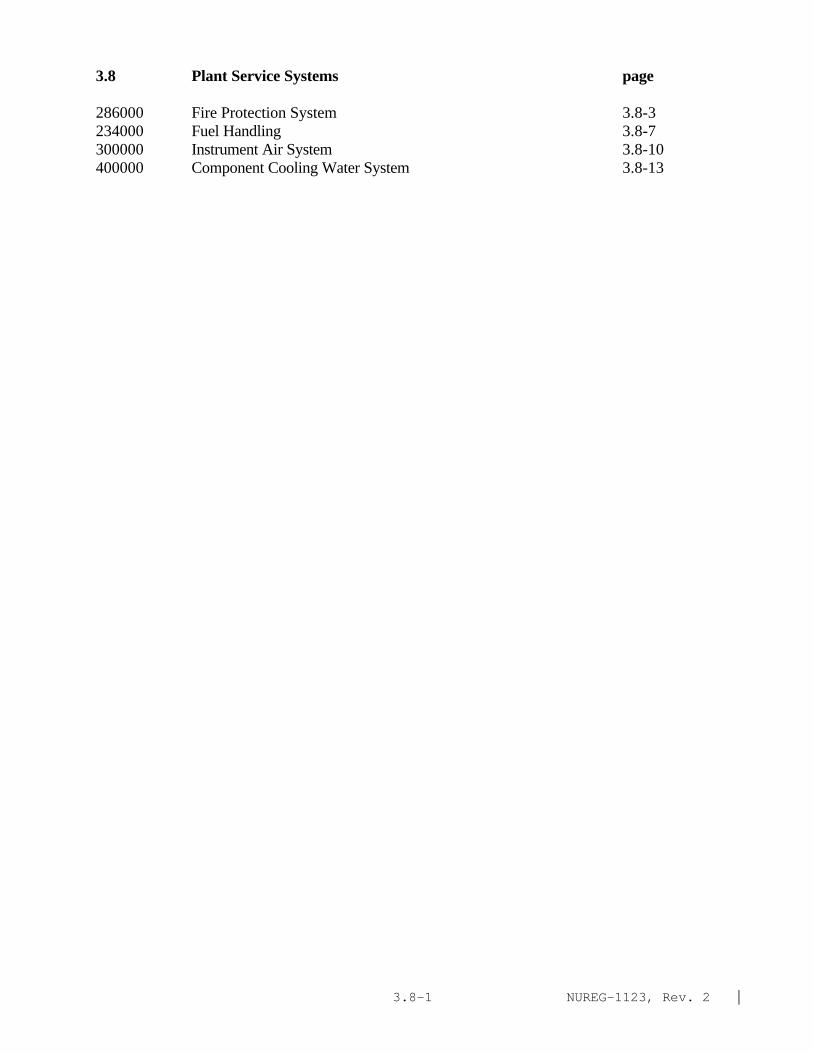
NUREG-1123, Rev. 2 |3.8-1
3.8 Plant Service Systems page
286000 Fire Protection System 3.8-3234000 Fuel Handling 3.8-7300000 Instrument Air System 3.8-10400000 Component Cooling Water System 3.8-13

NUREG-1123, Rev. 2 |3.8-2
This page left blank
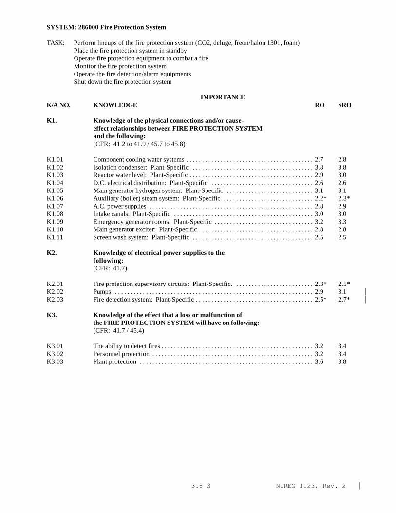
NUREG-1123, Rev. 2 |3.8-3
SYSTEM: 286000 Fire Protection System
TASK: Perform lineups of the fire protection system (CO2, deluge, freon/halon 1301, foam)Place the fire protection system in standbyOperate fire protection equipment to combat a fire Monitor the fire protection systemOperate the fire detection/alarm equipments Shut down the fire protection system
IMPORTANCE K/A NO. KNOWLEDGE RO SRO
K1. Knowledge of the physical connections and/or cause-effect relationships between FIRE PROTECTION SYSTEMand the following:(CFR: 41.2 to 41.9 / 45.7 to 45.8)
K1.01 Component cooling water systems . . . . . . . . . . . . . . . . . . . . . . . . . . . . . . . . . . . . . . . . . 2.7 2.8K1.02 Isolation condenser: Plant-Specific . . . . . . . . . . . . . . . . . . . . . . . . . . . . . . . . . . . . . . . 3.8 3.8K1.03 Reactor water level: Plant-Specific . . . . . . . . . . . . . . . . . . . . . . . . . . . . . . . . . . . . . . . . 2.9 3.0K1.04 D.C. electrical distribution: Plant-Specific . . . . . . . . . . . . . . . . . . . . . . . . . . . . . . . . . 2.6 2.6K1.05 Main generator hydrogen system: Plant-Specific . . . . . . . . . . . . . . . . . . . . . . . . . . . . 3.1 3.1K1.06 Auxiliary (boiler) steam system: Plant-Specific . . . . . . . . . . . . . . . . . . . . . . . . . . . . . 2.2* 2.3*K1.07 A.C. power supplies . . . . . . . . . . . . . . . . . . . . . . . . . . . . . . . . . . . . . . . . . . . . . . . . . . . . . 2.8 2.9K1.08 Intake canals: Plant-Specific . . . . . . . . . . . . . . . . . . . . . . . . . . . . . . . . . . . . . . . . . . . . . 3.0 3.0K1.09 Emergency generator rooms: Plant-Specific . . . . . . . . . . . . . . . . . . . . . . . . . . . . . . . . 3.2 3.3K1.10 Main generator exciter: Plant-Specific . . . . . . . . . . . . . . . . . . . . . . . . . . . . . . . . . . . . . 2.8 2.8K1.11 Screen wash system: Plant-Specific . . . . . . . . . . . . . . . . . . . . . . . . . . . . . . . . . . . . . . . 2.5 2.5
K2. Knowledge of electrical power supplies to thefollowing:(CFR: 41.7)
K2.01 Fire protection supervisory circuits: Plant-Specific. . . . . . . . . . . . . . . . . . . . . . . . . . 2.3* 2.5*K2.02 Pumps . . . . . . . . . . . . . . . . . . . . . . . . . . . . . . . . . . . . . . . . . . . . . . . . . . . . . . . . . . . . . . . . 2.9 3.1 |K2.03 Fire detection system: Plant-Specific . . . . . . . . . . . . . . . . . . . . . . . . . . . . . . . . . . . . . . 2.5* 2.7* |
K3. Knowledge of the effect that a loss or malfunction ofthe FIRE PROTECTION SYSTEM will have on following:(CFR: 41.7 / 45.4)
K3.01 The ability to detect fires . . . . . . . . . . . . . . . . . . . . . . . . . . . . . . . . . . . . . . . . . . . . . . . . . 3.2 3.4K3.02 Personnel protection . . . . . . . . . . . . . . . . . . . . . . . . . . . . . . . . . . . . . . . . . . . . . . . . . . . . 3.2 3.4K3.03 Plant protection . . . . . . . . . . . . . . . . . . . . . . . . . . . . . . . . . . . . . . . . . . . . . . . . . . . . . . . . 3.6 3.8

NUREG-1123, Rev. 2 |3.8-4
SYSTEM: 286000 Fire Protection System
Tasks as noted previously
IMPORTANCE K/A NO. KNOWLEDGE RO SRO
K4. Knowledge of FIRE PROTECTION SYSTEM design feature(s)and/or interlocks which provide for the following:(CFR: 41.7)(CFR: 41.5 / 45.3)(CFR: 41.7 / 45.7)(CFR: 41.5 / 45.5)(CFR: 41.5 / 45.6)(CFR: 41.7 / 45.7)(CFR: 41.7 / 45.5 to 45.8)
K4.01 Adequate supply of water for the fire protectionsystem . . . . . . . . . . . . . . . . . . . . . . . . . . . . . . . . . . . . . . . . . . . . . . . . . . . . . . . . . . . . . . . . 3.4 3.6
K4.02 Automatic system initiation . . . . . . . . . . . . . . . . . . . . . . . . . . . . . . . . . . . . . . . . . . . . . . 3.3 3.5K4.03 Maintenance of fire header pressure . . . . . . . . . . . . . . . . . . . . . . . . . . . . . . . . . . . . . . . 3.3 3.4K4.04 Personnel safety during halon and/or carbon dioxide
system actuation . . . . . . . . . . . . . . . . . . . . . . . . . . . . . . . . . . . . . . . . . . . . . . . . . . . . . . . 3.6 3.7K4.05 Fire protection capability during loss of off-site
power . . . . . . . . . . . . . . . . . . . . . . . . . . . . . . . . . . . . . . . . . . . . . . . . . . . . . . . . . . . . . . . . 3.7 3.8K4.06 Fire suppression capability that does not rely on the
displacement of oxygen (Halon): Plant-Specific . . . . . . . . . . . . . . . . . . . . . . . . . . . . 3.4 3.4K4.07 Diesel engine protection . . . . . . . . . . . . . . . . . . . . . . . . . . . . . . . . . . . . . . . . . . . . . . . . 3.3 3.3
K5. Knowledge of the operational implications of thefollowing concepts as they apply to FIRE PROTECTIONSYSTEM :(CFR: 41.5 / 45.3)
K5.01 Effect of carbon dioxide on fires . . . . . . . . . . . . . . . . . . . . . . . . . . . . . . . . . . . . . . . . . . 2.6 2.7K5.02 Effect of Halon on fires: Plant-Specific . . . . . . . . . . . . . . . . . . . . . . . . . . . . . . . . . . . 2.6 2.6K5.03 Effect of water spray on electrical components . . . . . . . . . . . . . . . . . . . . . . . . . . . . . . 3.3 3.4K5.04 Valve operation . . . . . . . . . . . . . . . . . . . . . . . . . . . . . . . . . . . . . . . . . . . . . . . . . . . . . . . . 2.9 2.9K5.05 Diesel operations . . . . . . . . . . . . . . . . . . . . . . . . . . . . . . . . . . . . . . . . . . . . . . . . . . . . . . 3.0* 3.1*|K5.06 Heat detection . . . . . . . . . . . . . . . . . . . . . . . . . . . . . . . . . . . . . . . . . . . . . . . . . . . . . . . . . 2.6 2.7|K5.07 Smoke detection . . . . . . . . . . . . . . . . . . . . . . . . . . . . . . . . . . . . . . . . . . . . . . . . . . . . . . . 2.6 2.7K5.08 Gas refrigeration: Plant-Specific . . . . . . . . . . . . . . . . . . . . . . . . . . . . . . . . . . . . . . . . . 2.4* 2.5*|
K6. Knowledge of the effect that a loss or malfunction ofthe following will have on the FIRE PROTECTION SYSTEM(CFR: 41.7 / 45.7)
K6.01 A.C. electrical distribution: Plant-Specific . . . . . . . . . . . . . . . . . . . . . . . . . . . . . . . . . 3.1 3.1K6.02 D. C . electrical distribution . . . . . . . . . . . . . . . . . . . . . . . . . . . . . . . . . . . . . . . . . . . . . . 2.8* 2.9*|K6.03 Applicable component cooling water system: Plant-
Specific . . . . . . . . . . . . . . . . . . . . . . . . . . . . . . . . . . . . . . . . . . . . . . . . . . . . . . . . . . . . . . 2.4* 2.5K6.04 Diesel fuel transfer system: Plant-Specific . . . . . . . . . . . . . . . . . . . . . . . . . . . . . . . . . 2.8 3.0K6.05 Screen wash system: Plant-Specific . . . . . . . . . . . . . . . . . . . . . . . . . . . . . . . . . . . . . . . 2.6 2.6

NUREG-1123, Rev. 2 |3.8-5
SYSTEM: 286000 Fire Protection System
Tasks as noted previously
IMPORTANCE K/A NO. ABILITY RO SRO
Al. Ability to predict and/or monitor changes inparameters associated with operating the FIREPROTECTION SYSTEM controls including:(CFR: 41.5 / 45.5)
A1.01 System pressure . . . . . . . . . . . . . . . . . . . . . . . . . . . . . . . . . . . . . . . . . . . . . . . . . . . . . . . . 2.9 2.9A1.02 System flow . . . . . . . . . . . . . . . . . . . . . . . . . . . . . . . . . . . . . . . . . . . . . . . . . . . . . . . . . . . 2.4* 2.5*A1.03 Fire doors . . . . . . . . . . . . . . . . . . . . . . . . . . . . . . . . . . . . . . . . . . . . . . . . . . . . . . . . . . . . . 2.8 3.1A1.04 Fire dampers . . . . . . . . . . . . . . . . . . . . . . . . . . . . . . . . . . . . . . . . . . . . . . . . . . . . . . . . . . 2.8 3.1A1.05 System lineups . . . . . . . . . . . . . . . . . . . . . . . . . . . . . . . . . . . . . . . . . . . . . . . . . . . . . . . . . 3.2 3.2A1.06 Tank pressure: Plant-Specific . . . . . . . . . . . . . . . . . . . . . . . . . . . . . . . . . . . . . . . . . . . . 2.9 3.0
A2. Ability to (a) predict the impacts of the following onthe FIRE PROTECTION SYSTEM ; and (b) based on thosepredictions, use procedures to correct, control, ormitigate the consequences of those abnormal conditionsor operations:(CFR: 41.5 / 45.6)
A2.01 †System logic failure: Plant-Specific . . . . . . . . . . . . . . . . . . . . . . . . . . . . . . . . . . . . . . 2.7 2.9A2.02 D.C. distribution failure: Plant-Specific . . . . . . . . . . . . . . . . . . . . . . . . . . . . . . . . . . . . 2.6* 2.7*A2.03 A.C. distribution failure: Plant-Specific . . . . . . . . . . . . . . . . . . . . . . . . . . . . . . . . . . . . 2.9 3.0A2.04 Applicable component cooling water system failure:
Plant-Specific . . . . . . . . . . . . . . . . . . . . . . . . . . . . . . . . . . . . . . . . . . . . . . . . . . . . . . . . . . 2.3* 2.4*A2.05 Fire protection diesel trips . . . . . . . . . . . . . . . . . . . . . . . . . . . . . . . . . . . . . . . . . . . . . . . 3.1 3.3A2.06 Low fire main pressure: Plant-Specific . . . . . . . . . . . . . . . . . . . . . . . . . . . . . . . . . . . . 3.1 3.2A2.07 Inadvertent system initiation . . . . . . . . . . . . . . . . . . . . . . . . . . . . . . . . . . . . . . . . . . . . . . 2.9 2.9A2.08 Failure to actuate when required . . . . . . . . . . . . . . . . . . . . . . . . . . . . . . . . . . . . . . . . . . . 3.2 3.3A2.09 Valve closures: Plant-Specific . . . . . . . . . . . . . . . . . . . . . . . . . . . . . . . . . . . . . . . . . . . . 2.7 2.8A2.10 Valve openings: Plant-Specific . . . . . . . . . . . . . . . . . . . . . . . . . . . . . . . . . . . . . . . . . . . 2.6* 2.7A2.11 Pump trips: Plant-Specific . . . . . . . . . . . . . . . . . . . . . . . . . . . . . . . . . . . . . . . . . . . . . . . 3.1 3.2A2.12 Low diesel fuel supply: Plant-Specific . . . . . . . . . . . . . . . . . . . . . . . . . . . . . . . . . . . . . 3.1 3.3
A3. Ability to monitor automatic operations of the FIREPROTECTION SYSTEM including:(CFR: 41.7 / 45.7)
A3.01 Fire water pump start . . . . . . . . . . . . . . . . . . . . . . . . . . . . . . . . . . . . . . . . . . . . . . . . . . . . 3.4 3.4A3.02 Fire main pressure . . . . . . . . . . . . . . . . . . . . . . . . . . . . . . . . . . . . . . . . . . . . . . . . . . . . . . 3.1 3.2A3.03 Actuation of fire detectors . . . . . . . . . . . . . . . . . . . . . . . . . . . . . . . . . . . . . . . . . . . . . . . 3.3 3.3A3.04 System initiation . . . . . . . . . . . . . . . . . . . . . . . . . . . . . . . . . . . . . . . . . . . . . . . . . . . . . . . . 3.2 3.3A3.05 Fire doors . . . . . . . . . . . . . . . . . . . . . . . . . . . . . . . . . . . . . . . . . . . . . . . . . . . . . . . . . . . . . 3.0 3.1A3.06 Fire dampers . . . . . . . . . . . . . . . . . . . . . . . . . . . . . . . . . . . . . . . . . . . . . . . . . . . . . . . . . . . 3.0 3.1
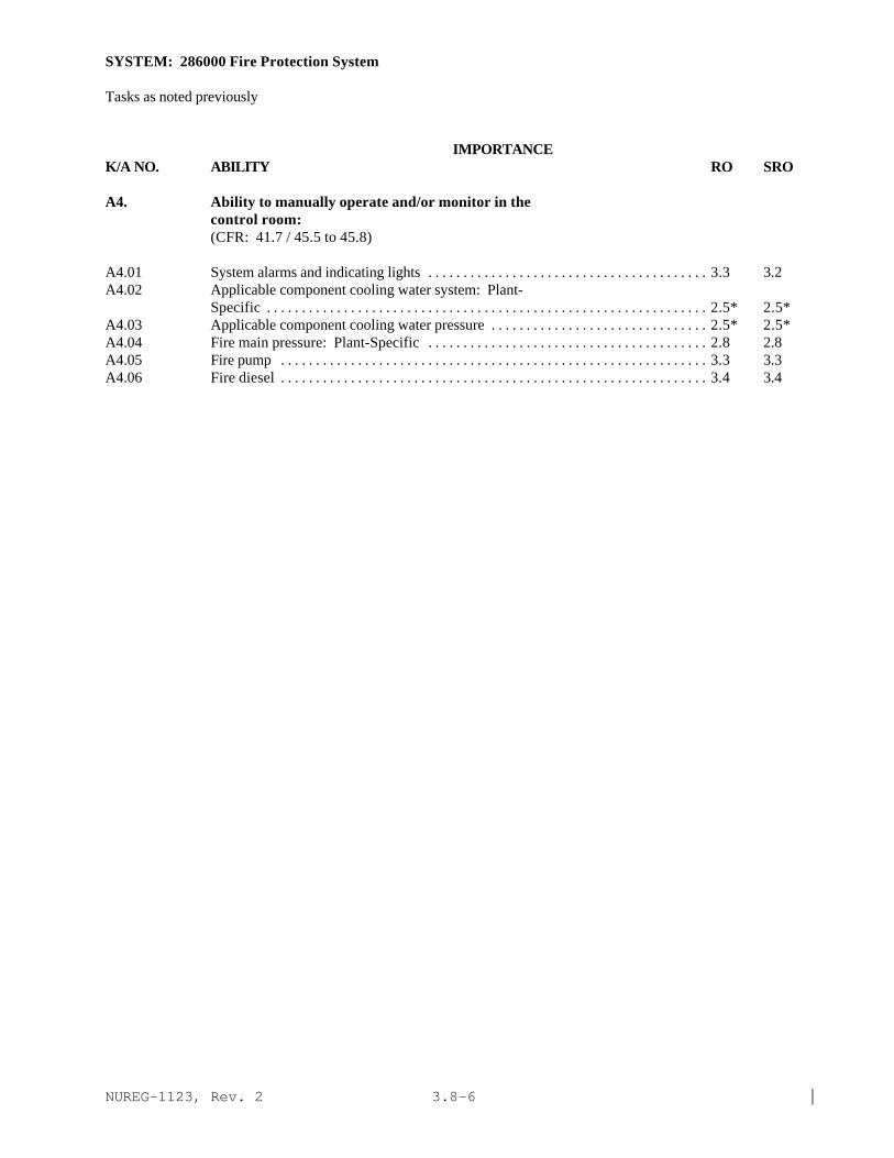
NUREG-1123, Rev. 2 |3.8-6
SYSTEM: 286000 Fire Protection System
Tasks as noted previously
IMPORTANCE K/A NO. ABILITY RO SRO
A4. Ability to manually operate and/or monitor in thecontrol room:(CFR: 41.7 / 45.5 to 45.8)
A4.01 System alarms and indicating lights . . . . . . . . . . . . . . . . . . . . . . . . . . . . . . . . . . . . . . . . 3.3 3.2A4.02 Applicable component cooling water system: Plant-
Specific . . . . . . . . . . . . . . . . . . . . . . . . . . . . . . . . . . . . . . . . . . . . . . . . . . . . . . . . . . . . . . . 2.5* 2.5*A4.03 Applicable component cooling water pressure . . . . . . . . . . . . . . . . . . . . . . . . . . . . . . . 2.5* 2.5*A4.04 Fire main pressure: Plant-Specific . . . . . . . . . . . . . . . . . . . . . . . . . . . . . . . . . . . . . . . . 2.8 2.8A4.05 Fire pump . . . . . . . . . . . . . . . . . . . . . . . . . . . . . . . . . . . . . . . . . . . . . . . . . . . . . . . . . . . . . 3.3 3.3A4.06 Fire diesel . . . . . . . . . . . . . . . . . . . . . . . . . . . . . . . . . . . . . . . . . . . . . . . . . . . . . . . . . . . . . 3.4 3.4
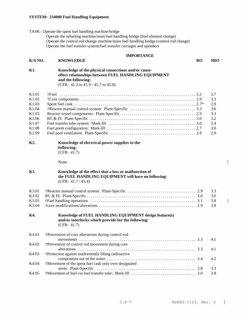
NUREG-1123, Rev. 2 |3.8-7
SYSTEM: 234000 Fuel Handling Equipment
TASK: Operate the spent fuel handling machine/bridgeOperate the refueling machine/main fuel handling bridge (fuel element change)Operate the control rod change machine/main fuel handling bridge (control rod change)Operate the fuel transfer system/fuel transfer carriages and upenders
IMPORTANCE K/A NO. KNOWLEDGE RO SRO
K1. Knowledge of the physical connections and/or cause-effect relationships between FUEL HANDLING EQUIPMENTand the following:(CFR: 41.2 to 41.9 / 45.7 to 45.8)
K1.01 †Fuel . . . . . . . . . . . . . . . . . . . . . . . . . . . . . . . . . . . . . . . . . . . . . . . . . . . . . . . . . . . . . . . . . . . . . . 3.2 3.7K1.02 †Core components . . . . . . . . . . . . . . . . . . . . . . . . . . . . . . . . . . . . . . . . . . . . . . . . . . . . . . . . . . . 2.9 3.3K1.03 Spent fuel cask . . . . . . . . . . . . . . . . . . . . . . . . . . . . . . . . . . . . . . . . . . . . . . . . . . . . . . . . . . . . . . . 2.7* 2.9K1.04 †Reactor manual control system: Plant-Specific . . . . . . . . . . . . . . . . . . . . . . . . . . . . . . . . . . 3.3 3.6K1.05 Reactor vessel components: Plant-Specific . . . . . . . . . . . . . . . . . . . . . . . . . . . . . . . . . . . . . . 2.9 3.3K1.06 RC & IS: Plant-Specific . . . . . . . . . . . . . . . . . . . . . . . . . . . . . . . . . . . . . . . . . . . . . . . . . . . . . . . 3.0 3.2K1.07 Fuel transfer tube system: Mark-III . . . . . . . . . . . . . . . . . . . . . . . . . . . . . . . . . . . . . . . . . . . . . 3.0 3.4K1.08 Fuel pools configuration: Mark-III . . . . . . . . . . . . . . . . . . . . . . . . . . . . . . . . . . . . . . . . . . . . . . 2.7 3.0K1.09 Fuel pool ventilation: Plant-Specific . . . . . . . . . . . . . . . . . . . . . . . . . . . . . . . . . . . . . . . . . . . . 2.8 2.9
K2. Knowledge of electrical power supplies to thefollowing:(CFR: 41.7)
None |
K3. Knowledge of the effect that a loss or malfunction ofthe FUEL HANDLING EQUIPMENT will have on following:(CFR: 41.7 / 45.4)
K3.01 †Reactor manual control system: Plant-Specific . . . . . . . . . . . . . . . . . . . . . . . . . . . . . . . . . . . 2.9 3.3K3.02 RC & IS: Plant-Specific . . . . . . . . . . . . . . . . . . . . . . . . . . . . . . . . . . . . . . . . . . . . . . . . . . . . . . . . 3.0 3.0K3.03 †Fuel handling operations . . . . . . . . . . . . . . . . . . . . . . . . . . . . . . . . . . . . . . . . . . . . . . . . . . . . . . . 3.1 3.8 |K3.04 †core modifications/alterations . . . . . . . . . . . . . . . . . . . . . . . . . . . . . . . . . . . . . . . . . . . . . . . . . . 2.9 3.8
K4. Knowledge of FUEL HANDLING EQUIPMENT design feature(s)and/or interlocks which provide for the following:(CFR: 41.7)
K4.01 †Prevention of core alterations during control rodmovements . . . . . . . . . . . . . . . . . . . . . . . . . . . . . . . . . . . . . . . . . . . . . . . . . . . . . . . . . . . . 3.3 4.1
K4.02 †Prevention of control rod movement during corealterations . . . . . . . . . . . . . . . . . . . . . . . . . . . . . . . . . . . . . . . . . . . . . . . . . . . . . . . . . . . . . 3.3 4.1
K4.03 †Protection against inadvertently lifting radioactivecomponents out of the water . . . . . . . . . . . . . . . . . . . . . . . . . . . . . . . . . . . . . . . . . . . . . . 3.4 4.2
K4.04 †Movement of the spent fuel cask only over designatedareas: Plant-Specific . . . . . . . . . . . . . . . . . . . . . . . . . . . . . . . . . . . . . . . . . . . . . . . . . . . 2.8 3.3
K4.05 †Movement of fuel via fuel transfer tube: Mark-III . . . . . . . . . . . . . . . . . . . . . . . . . . . . . . . . . 3.0 3.8
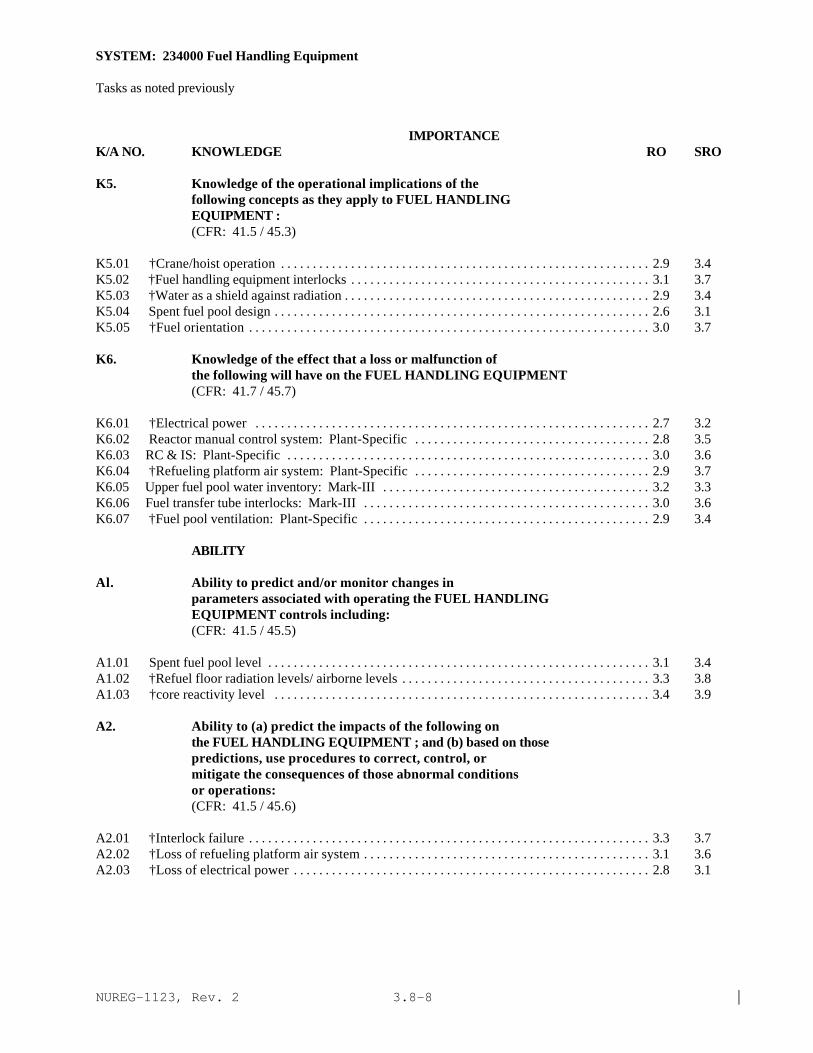
NUREG-1123, Rev. 2 |3.8-8
SYSTEM: 234000 Fuel Handling Equipment
Tasks as noted previously
IMPORTANCE K/A NO. KNOWLEDGE RO SRO
K5. Knowledge of the operational implications of thefollowing concepts as they apply to FUEL HANDLINGEQUIPMENT :(CFR: 41.5 / 45.3)
K5.01 †Crane/hoist operation . . . . . . . . . . . . . . . . . . . . . . . . . . . . . . . . . . . . . . . . . . . . . . . . . . . . . . . . . . 2.9 3.4K5.02 †Fuel handling equipment interlocks . . . . . . . . . . . . . . . . . . . . . . . . . . . . . . . . . . . . . . . . . . . . . . . 3.1 3.7K5.03 †Water as a shield against radiation . . . . . . . . . . . . . . . . . . . . . . . . . . . . . . . . . . . . . . . . . . . . . . . . 2.9 3.4K5.04 Spent fuel pool design . . . . . . . . . . . . . . . . . . . . . . . . . . . . . . . . . . . . . . . . . . . . . . . . . . . . . . . . . . . 2.6 3.1K5.05 †Fuel orientation . . . . . . . . . . . . . . . . . . . . . . . . . . . . . . . . . . . . . . . . . . . . . . . . . . . . . . . . . . . . . . . 3.0 3.7
K6. Knowledge of the effect that a loss or malfunction ofthe following will have on the FUEL HANDLING EQUIPMENT(CFR: 41.7 / 45.7)
K6.01 †Electrical power . . . . . . . . . . . . . . . . . . . . . . . . . . . . . . . . . . . . . . . . . . . . . . . . . . . . . . . . . . . . . . 2.7 3.2K6.02 Reactor manual control system: Plant-Specific . . . . . . . . . . . . . . . . . . . . . . . . . . . . . . . . . . . . . 2.8 3.5K6.03 RC & IS: Plant-Specific . . . . . . . . . . . . . . . . . . . . . . . . . . . . . . . . . . . . . . . . . . . . . . . . . . . . . . . . . 3.0 3.6K6.04 †Refueling platform air system: Plant-Specific . . . . . . . . . . . . . . . . . . . . . . . . . . . . . . . . . . . . . 2.9 3.7K6.05 Upper fuel pool water inventory: Mark-III . . . . . . . . . . . . . . . . . . . . . . . . . . . . . . . . . . . . . . . . . . 3.2 3.3K6.06 Fuel transfer tube interlocks: Mark-III . . . . . . . . . . . . . . . . . . . . . . . . . . . . . . . . . . . . . . . . . . . . . 3.0 3.6K6.07 †Fuel pool ventilation: Plant-Specific . . . . . . . . . . . . . . . . . . . . . . . . . . . . . . . . . . . . . . . . . . . . . 2.9 3.4
ABILITY
Al. Ability to predict and/or monitor changes inparameters associated with operating the FUEL HANDLINGEQUIPMENT controls including:(CFR: 41.5 / 45.5)
A1.01 Spent fuel pool level . . . . . . . . . . . . . . . . . . . . . . . . . . . . . . . . . . . . . . . . . . . . . . . . . . . . . . . . . . . . 3.1 3.4A1.02 †Refuel floor radiation levels/ airborne levels . . . . . . . . . . . . . . . . . . . . . . . . . . . . . . . . . . . . . . . 3.3 3.8A1.03 †core reactivity level . . . . . . . . . . . . . . . . . . . . . . . . . . . . . . . . . . . . . . . . . . . . . . . . . . . . . . . . . . . 3.4 3.9
A2. Ability to (a) predict the impacts of the following onthe FUEL HANDLING EQUIPMENT ; and (b) based on thosepredictions, use procedures to correct, control, ormitigate the consequences of those abnormal conditionsor operations:(CFR: 41.5 / 45.6)
A2.01 †Interlock failure . . . . . . . . . . . . . . . . . . . . . . . . . . . . . . . . . . . . . . . . . . . . . . . . . . . . . . . . . . . . . . . 3.3 3.7A2.02 †Loss of refueling platform air system . . . . . . . . . . . . . . . . . . . . . . . . . . . . . . . . . . . . . . . . . . . . . 3.1 3.6A2.03 †Loss of electrical power . . . . . . . . . . . . . . . . . . . . . . . . . . . . . . . . . . . . . . . . . . . . . . . . . . . . . . . . 2.8 3.1

NUREG-1123, Rev. 2 |3.8-9
SYSTEM: 234000 Fuel Handling Equipment
Tasks as noted previously
IMPORTANCE K/A NO. ABILITY RO SRO
A3. Ability to monitor automatic operations of the FUELHANDLING EQUIPMENT including:(CFR: 41.7 / 45.7)
A3.01 †Crane/refuel bridge movement: Plant-Specific . . . . . . . . . . . . . . . . . . . . . . . . . . . . . . . . . . . . . 2.6 3.6A3.02 †Interlock operation . . . . . . . . . . . . . . . . . . . . . . . . . . . . . . . . . . . . . . . . . . . . . . . . . . . . . . . . . . . 3.1 3.7
A4. Ability to manually operate and/or monitor in thecontrol room:(CFR: 41.7 / 45.5 to 45.8)
A4.01 †Neutron monitoring system . . . . . . . . . . . . . . . . . . . . . . . . . . . . . . . . . . . . . . . . . . . . . . . . . . . . 3.7 3.9A4.02 Control rod drive system . . . . . . . . . . . . . . . . . . . . . . . . . . . . . . . . . . . . . . . . . . . . . . . . . 3.4 3.7

NUREG-1123, Rev. 2 |3.8-10
SYSTEM: 300000 Instrument Air System (IAS)
Task: Perform lineups of the IASStart up the IASMonitor the IASShift instrument air compressorsOperate instrument air compressorsOperate system air dryersPerform testing of automatic operation of the IAS
IMPORTANCE K/A NO. KNOWLEDGE RO SRO
K1 Knowledge of the connections and / or cause effectrelationships between INSTRUMENT AIR SYSTEM and the following:(CFR: 41.2 to 41.9 / 45.7 to 45.8)
K1.01 Sensor air . . . . . . . . . . . . . . . . . . . . . . . . . . . . . . . . . . . . . . . . . . . . . . . . . . . . . . . . . . . . . 2.4 2.7K1.02 Service air . . . . . . . . . . . . . . . . . . . . . . . . . . . . . . . . . . . . . . . . . . . . . . . . . . . . . . . . . . . . . 2.7 2.8K1.03 Containment air . . . . . . . . . . . . . . . . . . . . . . . . . . . . . . . . . . . . . . . . . . . . . . . . . . . . . . . . 2.8 2.9K1.04 Cooling water to compressor . . . . . . . . . . . . . . . . . . . . . . . . . . . . . . . . . . . . . . . . . . . . . 2.8 2.9K1.05 Main Steam Isolation Valve air . . . . . . . . . . . . . . . . . . . . . . . . . . . . . . . . . . . . . . . . . . . . 3.1 3.2
K2 Knowledge of electrical power supplies to the following:(CFR: 41.7)
K2.01 Instrument air compressor . . . . . . . . . . . . . . . . . . . . . . . . . . . . . . . . . . . . . . . . . . . . . . . . 2.8 2.8K2.02 Emergency air compressor . . . . . . . . . . . . . . . . . . . . . . . . . . . . . . . . . . . . . . . . . . . . . . . 3.0 3.0
K3. Knowledge of the effect that a loss or malfunction of the . . . . . . . . . . . . . . . . . . . . . .(INSTRUMENT AIR SYSTEM) will have on the following:
(CFR: 41.7 / 45.6)
K3.01 Containment air system . . . . . . . . . . . . . . . . . . . . . . . . . . . . . . . . . . . . . . . . . . . . . . . . . . 2.7 2.9K3.02 Systems having pneumatic valves and controls . . . . . . . . . . . . . . . . . . . . . . . . . . . . . . . 3.3 3.4K3.03 Cross-tied units . . . . . . . . . . . . . . . . . . . . . . . . . . . . . . . . . . . . . . . . . . . . . . . . . . . . . . . . 2.9 3.0
K4. Knowledge of (INSTRUMENT AIR SYSTEM) design feature(s) and or interlocks which provide for the following: (CFR: 41.7)
K4.01 Manual/automatic transfers of control . . . . . . . . . . . . . . . . . . . . . . . . . . . . . . . . . . . . . . 2.8 2.9K4.02 Cross-over to other air systems . . . . . . . . . . . . . . . . . . . . . . . . . . . . . . . . . . . . . . . . . . . 3.0 3.0K4.03 Securing of IAS upon loss of cooling water . . . . . . . . . . . . . . . . . . . . . . . . . . . . . . . . . 2.8 2.8
K5. Knowledge of the operational implications of the following concepts as they apply to the INSTRUMENT AIR SYSTEM:(CFR: 41.5 / 45.3)
K5.01 Air compressors . . . . . . . . . . . . . . . . . . . . . . . . . . . . . . . . . . . . . . . . . . . . . . . . . . . . . . . . 2.5 2.5K5.02 Pressure gauges . . . . . . . . . . . . . . . . . . . . . . . . . . . . . . . . . . . . . . . . . . . . . . . . . . . . . . . . 2.3 2.2

NUREG-1123, Rev. 2 |3.8-11
SYSTEM: 300000 Instrument Air System (IAS)
IMPORTANCE K/A NO. KNOWLEDGE RO SRO
K5.03 Temperature indicators . . . . . . . . . . . . . . . . . . . . . . . . . . . . . . . . . . . . . . . . . . . . . . . . . . 2.1 2.1K5.04 Service air refusal valve . . . . . . . . . . . . . . . . . . . . . . . . . . . . . . . . . . . . . . . . . . . . . . . . . . 2.3 2.3K5.06 Air dryers . . . . . . . . . . . . . . . . . . . . . . . . . . . . . . . . . . . . . . . . . . . . . . . . . . . . . . . . . . . . . 2.4 2.5K5.07 Valves . . . . . . . . . . . . . . . . . . . . . . . . . . . . . . . . . . . . . . . . . . . . . . . . . . . . . . . . . . . . . . . . 2.4 2.3K5.08 Sensors and detectors . . . . . . . . . . . . . . . . . . . . . . . . . . . . . . . . . . . . . . . . . . . . . . . . . . . 2.3 2.5K5.09 Controllers and positioners . . . . . . . . . . . . . . . . . . . . . . . . . . . . . . . . . . . . . . . . . . . . . . . 2.0 2.1K5.10 Motors . . . . . . . . . . . . . . . . . . . . . . . . . . . . . . . . . . . . . . . . . . . . . . . . . . . . . . . . . . . . . . . . 2.1 2.2K5.11 Heat exchangers and condensers . . . . . . . . . . . . . . . . . . . . . . . . . . . . . . . . . . . . . . . . . . . 2.2 2.2K5.12 Breakers, relays and disconnects . . . . . . . . . . . . . . . . . . . . . . . . . . . . . . . . . . . . . . . . . . 2.2 2.2K5.13 Filters . . . . . . . . . . . . . . . . . . . . . . . . . . . . . . . . . . . . . . . . . . . . . . . . . . . . . . . . . . . . . . . . 2.9 2.9
K6 Knowledge of the effect that a loss or malfunction of the following will have on the INSTRUMENT AIR SYSTEM: (CFR: 41.7 / 45.7)
K6.01 Air compressors . . . . . . . . . . . . . . . . . . . . . . . . . . . . . . . . . . . . . . . . . . . . . . . . . . . . . . . . 2.2 2.2K6.02 Pressure gauges . . . . . . . . . . . . . . . . . . . . . . . . . . . . . . . . . . . . . . . . . . . . . . . . . . . . . . . . 2.4 2.4K6.03 Temperature indicators . . . . . . . . . . . . . . . . . . . . . . . . . . . . . . . . . . . . . . . . . . . . . . . . . . 2.7 2.7K6.04 Service air refusal valve . . . . . . . . . . . . . . . . . . . . . . . . . . . . . . . . . . . . . . . . . . . . . . . . . . 2.6 2.5K6.06 Air dryers . . . . . . . . . . . . . . . . . . . . . . . . . . . . . . . . . . . . . . . . . . . . . . . . . . . . . . . . . . . . . 2.3 2.3K6.07 Valves . . . . . . . . . . . . . . . . . . . . . . . . . . . . . . . . . . . . . . . . . . . . . . . . . . . . . . . . . . . . . . . . 2.5 2.6K6.08 Sensors and detectors . . . . . . . . . . . . . . . . . . . . . . . . . . . . . . . . . . . . . . . . . . . . . . . . . . . 2.3 2.3K6.09 Controllers and positioners . . . . . . . . . . . . . . . . . . . . . . . . . . . . . . . . . . . . . . . . . . . . . . . 2.3 2.3K6.10 Motors . . . . . . . . . . . . . . . . . . . . . . . . . . . . . . . . . . . . . . . . . . . . . . . . . . . . . . . . . . . . . . . . 2.3 2.4K6.11 Heat exchangers and condensers . . . . . . . . . . . . . . . . . . . . . . . . . . . . . . . . . . . . . . . . . . . 2.3 2.3K6.12 Breakers, relays and disconnects . . . . . . . . . . . . . . . . . . . . . . . . . . . . . . . . . . . . . . . . . . 2.9 2.9K6.13 Filters . . . . . . . . . . . . . . . . . . . . . . . . . . . . . . . . . . . . . . . . . . . . . . . . . . . . . . . . . . . . . . . . 2.8 2.3
No. ABILITY
A1. Ability to predict and / or monitor changes in parameters . . . . . . . . . . . . . . . . . associatedwith operating the INSTRUMENT AIR SYSTEM controls including:(CFR: 41.5 / 45.5)
None |
A2. Ability to (a) predict the impacts of the following on the . . . . . . . . . . . . . . . . . .INSTRUMENT AIR SYSTEM and (b) based on those predictions,use procedures to correct, control, or mitigate the consequences of those abnormal operation: (CFR: 41.5 / 45.6)
A2.01 Air dryer and filter malfunctions . . . . . . . . . . . . . . . . . . . . . . . . . . . . . . . . . . . . . . . . . . 2.9 2.8

NUREG-1123, Rev. 2 |3.8-12
SYSTEM: 300000 Instrument Air System (IAS)
IMPORTANCE K/A NO. KNOWLEDGE RO SRO
A3. Ability to monitor automatic operations of the INSTRUMENT AIR SYSTEM including:(CFR: 41.7 / 45.7)
A3.01 Air pressure 2.3 2.1A3.02 Air temperature 2.9 2.7
A4. Ability to manually operate and / or monitor in the control room: (CFR: 41.7 / 45.5 to 45.8)
A4.01 Pressure gauges 2.6 2.7

NUREG-1123, Rev. 2 |3.8-13
SYSTEM: 400000 Component Cooling Water System (CCWS)
IMPORTANCE K/A NO. KNOWLEDGE RO SRO
Task: Perform CCWS component operability testPerform CCWS flow path verificationPerform CCWS pump testPerform CCW flow balanceDetermine CCWS leak rate from RCS
K1. Knowledge of the physical connections and / or cause-effect relationships between CCWS and the following:(CFR: 41.2 to 41.9 / 45.7 to 45.8)
K1.01 Service water system . . . . . . . . . . . . . . . . . . . . . . . . . . . . . . . . . . . . . . . . . . . . . . . . . . . . 3.2 3.3K1.02 Loads cooled by CCWS . . . . . . . . . . . . . . . . . . . . . . . . . . . . . . . . . . . . . . . . . . . . . . . . . . 3.2 3.4K1.03 Radiation monitoring systems . . . . . . . . . . . . . . . . . . . . . . . . . . . . . . . . . . . . . . . . . . . . . 2.7 3.0K1.04 Reactor coolant system, in order to determine source (s)
of RCS leakage into CCWS . . . . . . . . . . . . . . . . . . . . . . . . . . . . . . . . . . . . . . . . . . . . . . . 2.9 3.1
K2. Knowledge of electrical power supplies to the following:(CFR: 41.7)
K2.01 CCW pumps . . . . . . . . . . . . . . . . . . . . . . . . . . . . . . . . . . . . . . . . . . . . . . . . . . . . . . . . . . . 2.9 3.0K2.02 CCW valves . . . . . . . . . . . . . . . . . . . . . . . . . . . . . . . . . . . . . . . . . . . . . . . . . . . . . . . . . . . . 2.9 2.9
K3. Knowledge of the effect that a loss or malfunction of the CCWS will have on the following:(CFR: 41.7 / 45.6)
K3.01 Loads cooled by CCWS . . . . . . . . . . . . . . . . . . . . . . . . . . . . . . . . . . . . . . . . . . . . . . . . . . 2.9 3.3
K4. Knowledge of CCWS design feature(s) and or interlocks which provide for the following:(CFR: 41.7)
K4.01 Automatic start of standby pump . . . . . . . . . . . . . . . . . . . . . . . . . . . . . . . . . . . . . . . . . . . 3.4 3.9
K5. Knowledge of the operational implications of the following concepts as they apply to the CCWS:(CFR: 41.5 / 45.3)
K5.01 Chemistry control . . . . . . . . . . . . . . . . . . . . . . . . . . . . . . . . . . . . . . . . . . . . . . . . . . . . . . 1.9 2.0

NUREG-1123, Rev. 2 |3.8-14
IMPORTANCE K/A NO. KNOWLEDGE RO SRO
K6 Knowledge of the effect that a loss or malfunction of the following will have on the CCWS:(CFR: 41.7 / 45.7)
K6.01 Valves . . . . . . . . . . . . . . . . . . . . . . . . . . . . . . . . . . . . . . . . . . . . . . . . . . . . . . . . . . . . . . . . 2.7 2.8K6.02 Sensors and detectors . . . . . . . . . . . . . . . . . . . . . . . . . . . . . . . . . . . . . . . . . . . . . . . . . . . 2.3 2.4K6.03 Controllers and positioners . . . . . . . . . . . . . . . . . . . . . . . . . . . . . . . . . . . . . . . . . . . . . . . 2.4 2.6K6.05 Pumps . . . . . . . . . . . . . . . . . . . . . . . . . . . . . . . . . . . . . . . . . . . . . . . . . . . . . . . . . . . . . . . . 3.0 3.1K6.05 Motors . . . . . . . . . . . . . . . . . . . . . . . . . . . . . . . . . . . . . . . . . . . . . . . . . . . . . . . . . . . . . . . . 2.8 2.9K6.06 Heat exchangers and condensers . . . . . . . . . . . . . . . . . . . . . . . . . . . . . . . . . . . . . . . . . . . 2.9 2.9K6.07 Breakers, relays, and disconnects . . . . . . . . . . . . . . . . . . . . . . . . . . . . . . . . . . . . . . . . . . 2.7 2.8
No. ABILITY
A1. Ability to predict and / or monitor changes in parameters . . . . . . . . . . . . . . . . . . . . .associated with operating the CCWS controls including:(CFR: 41.5 / 45.5)
A1.01 CCW flow rate . . . . . . . . . . . . . . . . . . . . . . . . . . . . . . . . . . . . . . . . . . . . . . . . . . . . . . . . . 2.8 2.8A1.02 CCW temperature . . . . . . . . . . . . . . . . . . . . . . . . . . . . . . . . . . . . . . . . . . . . . . . . . . . . . . . 2.8 2.8A1.03 CCW Pressure . . . . . . . . . . . . . . . . . . . . . . . . . . . . . . . . . . . . . . . . . . . . . . . . . . . . . . . . . 2.7 2.7A1.04 Surge Tank Level . . . . . . . . . . . . . . . . . . . . . . . . . . . . . . . . . . . . . . . . . . . . . . . . . . . . . . . 2.8 2.8
A2. Ability to (a) predict the impacts of the following on the CCWS and (b) based on those predictions, use procedures to correct, control, or mitigate the consequences of those abnormal operation:(CFR: 41.5 / 45.6)
A2.01 Loss of CCW pump . . . . . . . . . . . . . . . . . . . . . . . . . . . . . . . . . . . . . . . . . . . . . . . . . . . . . 3.3 3.4A2.02 High/low surge tank level . . . . . . . . . . . . . . . . . . . . . . . . . . . . . . . . . . . . . . . . . . . . . . . . 2.8 3.0A2.03 High/low CCW temperature . . . . . . . . . . . . . . . . . . . . . . . . . . . . . . . . . . . . . . . . . . . . . . 2.9 3.0A2.04 Radiation monitoring system alarm . . . . . . . . . . . . . . . . . . . . . . . . . . . . . . . . . . . . . . . . 2.9 3.0
A3. Ability to monitor automatic operations of the CCWS including:(CFR: 41.7 / 45.7)
A3.01 Setpoints on instrument signal levels for normal operations,warnings, and trips that are applicable to the CCWS . . . . . . . . . . . . . . . . . . . . . . . . . . . 3.0 3.0
A4. Ability to manually operate and / or monitor in the control room: (CFR: 41.7 / 45.5 to 45.8)
A4.01 CCW indications and control . . . . . . . . . . . . . . . . . . . . . . . . . . . . . . . . . . . . . . . . . . . . . 3.1 3.0

NUREG-1123, Rev. 2 |3.9-1
3.9 Radioactivity Release page
239003 Main Steam Isolation Valve Leakage Control System 3.9-3271000 Offgas System 3.9-7288000 Plant Ventilation Systems 3.9-11272000 Radiation Monitoring System 3.9-14268000 Radwaste 3.9-18290002 Reactor Vessel Internals 3.9-21233000 Fuel Pool Cooling and Clean-up 3.9-24261000 Standby Gas Treatment System 3.9-29290003 Control Room Heating, Ventilation and Air Conditioning 3.9-33

NUREG-1123, Rev. 2 |3.9-2
This page left blank

NUREG-1123, Rev. 2 |3.9-3
SYSTEM: 239003 MSIV Leakage Control System
TASK: Perform one train MSLCS inoperable surveillancePerform main steam leakage control system operational test (write inPerform one train main steam leakage control system operability surveillance (write in)Perform monthly main steam leakage control system DIV 1 and DIV 2 fan and heater tests (write in)
IMPORTANCE K/A NO. KNOWLEDGE RO SRO
K1. Knowledge of the physical connections and/or cause-effect relationships between MSIV LEAKAGE CONTROLSYSTEM and the following:(CFR: 41.2 to 41.9 / 45.7 to 45.8)
K1.01 Main steam system: BWR-4,5,6(P-Spec) . . . . . . . . . . . . . . . . . . . . . . . . . . . . . . . . . . 3.3 3.4K1.02 Standby gas treatment system: BWR-4,5,6(P-Spec) . . . . . . . . . . . . . . . . . . . . . . . . . 2.9 3.0 |K1.03 Main steam line pressure instrumentation: BWR- |
4,5,6(P-Spec) . . . . . . . . . . . . . . . . . . . . . . . . . . . . . . . . . . . . . . . . . . . . . . . . . . . . . . . . . . 3.1 3.1K1.04 A.C. electrical distribution: BWR-4,5,6(P-Spec) . . . . . . . . . . . . . . . . . . . . . . . . . . . . 2.7 2.8K1.05 Steam tunnel: BWR-4,5,6(P-Spec) . . . . . . . . . . . . . . . . . . . . . . . . . . . . . . . . . . . . . . . 2.9 2.9K1.06 Radwaste system: BWR-4,5,6(P-Spec) . . . . . . . . . . . . . . . . . . . . . . . . . . . . . . . . . . . . 2.4 2.4K1.07 Floor drainage system: BWR-4,5,6(P-Spec) . . . . . . . . . . . . . . . . . . . . . . . . . . . . . . . . 1.9* 1.9*K1.08 Nuclear boiler instrumentation: BWR-4,5,6(P-Spec) . . . . . . . . . . . . . . . . . . . . . . . . 2.8 2.8
K2. Knowledge of electrical power supplies to thefollowing:(CFR: 41.7)
K2.01 Motor operated valves: BWR-4,5,6(P-Spec) . . . . . . . . . . . . . . . . . . . . . . . . . . . . . . . 2.3* 2.3*K2.02 Leakage control system blowers: BWR-4,5,6(P-Spec) . . . . . . . . . . . . . . . . . . . . . . . 1.9* 2.0*K2.03 Leakage control system heaters: BWR-4.5,6(P-Spec) . . . . . . . . . . . . . . . . . . . . . . . . 1.9* 2.0*
K3. Knowledge of the effect that a loss or malfunction ofthe MSIV LEAKAGE CONTROL SYSTEM will have onfollowing:(CFR: 41.5 / 45.3)
K3.01 †Radiation release to the environment: BWR-4,5,6(P-Spec) . . . . . . . . . . . . . . . . . . . . . . . . . . . . . . . . . . . . . . . . . . . . . . . . . . . . . . . . . . . . . . . . . 3.3 4.0
K4. Knowledge of MSIV LEAKAGE CONTROL SYSTEM designfeature(s) and/or interlocks which provide for thefollowing:(CFR: 41.7)
K4.01 Performance of its safety function following a loss ofoffsite power: BWR-4,5,6(P-Spec) . . . . . . . . . . . . . . . . . . . . . . . . . . . . . . . . . . . . . . . 3.2 3.5
K4.02 Performance of intended safety function following anysingle active component failure: BWR-4,5,6(P-Spec) . . . . . . . . . . . . . . . . . . . . . . . . 3.0 3.4
K4.03 The prevention of inadvertent system operation: BWR-4,5,6(P-Spec) . . . . . . . . . . . . . . . . . . . . . . . . . . . . . . . . . . . . . . . . . . . . . . . . . . . . . . . . . . 2.9 3.2

NUREG-1123, Rev. 2 |3.9-4
SYSTEM: 239003 MSIV Leakage Control System
Tasks as noted previously
IMPORTANCE K/A NO. KNOWLEDGE RO SRO
K4.04 Surveillance for system operability: BWR-4,5,6 . . . . . . . . . . . . . . . . . . . . . . . . . . . . 2.4 2.8K4.05 Assurance that any MSIV leakage will pass through the
system and into standby gas treatment prior to releaseto the atmosphere: BWR-4,5,6(P-Spec) . . . . . . . . . . . . . . . . . . . . . . . . . . . . . . . . . . . 2.4* 2.8*
K4.06 The depressurization of main steam piping prior torouting leakage through system: BWR-4,5,6 . . . . . . . . . . . . . . . . . . . . . . . . . . . . . . . . 3.1 3.3
K4.07 The reduction of MSIV leakage temperature: BWR-4,5,6(P-Spec) . . . . . . . . . . . . . . . . . . . . . . . . . . . . . . . . . . . . . . . . . . . . . . . . . . . . . . . . . . 2.4 2.4
K4.08 Prevention of collected condensate in system bleedlines: BWR-4,5,6(P-Spec) . . . . . . . . . . . . . . . . . . . . . . . . . . . . . . . . . . . . . . . . . . . . . . 2.3 2.4
K4.09 The dilution of MSIV leakage: BWR-4,5,6(P-Spec) . . . . . . . . . . . . . . . . . . . . . . . . . 2.4 2.4
K5. Knowledge of the operational implications of thefollowing concepts as they apply to MSIV LEAKAGECONTROL SYSTEM :(CFR: 41.7 / 45.4)
None|
K6. Knowledge of the effect that a loss or malfunction ofthe following will have on the MSIV LEAKAGE CONTROLSYSTEM :(CFR: 41.7 / 45.7)
K6.01 A.C. electrical distribution: BWR-4,5,6(P-Spec) . . . . . . . . . . . . . . . . . . . . . . . . . . . . 2.8 3.0K6.02 Standby gas treatment system: BWR-4,5,6(P-Spec) . . . . . . . . . . . . . . . . . . . . . . . . . 2.8 3.0K6.03 Nuclear boiler instrumentation: BWR-4,5,6(P-Spec) . . . . . . . . . . . . . . . . . . . . . . . . 2.6 2.9
ABILITY
A1. Ability to predict and/or monitor changes inparameters associated with operating the MSIV LEAKAGECONTROL SYSTEM controls including:(CFR: 41.5 / 45.5)
A1.01 Main steam line pressure: BWR-4,5,6 . . . . . . . . . . . . . . . . . . . . . . . . . . . . . . . . . . . . . 3.1 3.1A1.02 Heater operation: BWR-4,5,6(P-Spec) . . . . . . . . . . . . . . . . . . . . . . . . . . . . . . . . . . . . 2.6 2.6A1.03 Dilution air flow: BWR-4,5,6(P-Spec) . . . . . . . . . . . . . . . . . . . . . . . . . . . . . . . . . . . . . 2.4 2.6A1.04 Status indicating lights and alarms: BWR-4,5,6 . . . . . . . . . . . . . . . . . . . . . . . . . . . . . . 2.9 2.8A1.05 System lineup: BWR-4,5,6 . . . . . . . . . . . . . . . . . . . . . . . . . . . . . . . . . . . . . . . . . . . . . . . 3.0 2.9A1.06 MSIV leakage flow: BWR-4,5,6 . . . . . . . . . . . . . . . . . . . . . . . . . . . . . . . . . . . . . . . . . . 2.6 2.6A1.07 Reactor building temperature: BWR-4,5,6(P-Spec) . . . . . . . . . . . . . . . . . . . . . . . . . . 2.7 2.7

NUREG-1123, Rev. 2 |3.9-5
SYSTEM: 239003 MSIV Leakage Control System
Tasks as noted previously
IMPORTANCE K/A NO. ABILITY RO SRO
A2. Ability to (a) predict the impacts of the following onthe MSIV LEAKAGE CONTROL SYSTEM ; and (b) based onthose predictions, use procedures to correct, control,or mitigate the consequences of those abnormalconditions or operations:(CFR: 41.5 / 45.6)
A2.01 Inboard MSIV valve leakage: BWR-4,5,6 2.8 3.2A2.02 Outboard MSIV valves leakage: BWR-4,5,6 . . . . . . . . . . . . . . . . . . . . . . . . . . . . . . . . . 2.9 3.3A2.03 Low dilution air flow (inboard and/or outboard):
BWR-4,5,6(P-Spec) . . . . . . . . . . . . . . . . . . . . . . . . . . . . . . . . . . . . . . . . . . . . . . . . . . . . . 2.6 2.7A2.04 Outboard system logic failure: BWR-4,5,6 . . . . . . . . . . . . . . . . . . . . . . . . . . . . . . . . . . 2.7 3.0A2.05 Inboard system logic failure: BWR-4,5,6 . . . . . . . . . . . . . . . . . . . . . . . . . . . . . . . . . . . 2.7 3.0A2.06 Blower failure: BWR-4,5,6(P-Spec) . . . . . . . . . . . . . . . . . . . . . . . . . . . . . . . . . . . . . . . 2.6 2.6A2.07 Heater failure: BWR-4,5,6(P-Spec) . . . . . . . . . . . . . . . . . . . . . . . . . . . . . . . . . . . . . . . . 2.4 2.4A2.08 Motor operator valve failure(s): BWR-4,5,6 . . . . . . . . . . . . . . . . . . . . . . . . . . . . . . . . . 2.8 3.0A2.09 Outboard main steamline high pressure: BWR-4,5,6(P-
Spec) . . . . . . . . . . . . . . . . . . . . . . . . . . . . . . . . . . . . . . . . . . . . . . . . . . . . . . . . . . . . . . . . . . 2.8 3.0A2.10 A.C. distribution power failures: BWR-4,5,6 . . . . . . . . . . . . . . . . . . . . . . . . . . . . . . . . 2.8 3.0A2.11 High reactor pressure: BWR-4,5,6 . . . . . . . . . . . . . . . . . . . . . . . . . . . . . . . . . . . . . . . . . 3.1 3.3A2.12 MSIV valve failure to close: BWR-4,5,6 . . . . . . . . . . . . . . . . . . . . . . . . . . . . . . . . . . . . 3.5 3.8
A3. Ability to monitor automatic operations of the MSIVLEAKAGE CONTROL SYSTEM including:(CFR: 41.7 / 45.7)
A3.01 System logic initiation: BWR-4,5,6(P-Spec) . . . . . . . . . . . . . . . . . . . . . . . . . . . . . . . . 3.0 2.8A3.02 Main steamline pressures: BWR-4,5,6 . . . . . . . . . . . . . . . . . . . . . . . . . . . . . . . . . . . . . 3.1 2.8A3.03 Dilution air flaws: BWR-4,5,6(P-Spec) . . . . . . . . . . . . . . . . . . . . . . . . . . . . . . . . . . . . . 2.4 2.3A3.04 MSIV leakage flows: BWR-4,5,6(P-Spec) . . . . . . . . . . . . . . . . . . . . . . . . . . . . . . . . . . 2.8 2.6A3.05 Heater operation: BWR-4,5,6(P-Spec) . . . . . . . . . . . . . . . . . . . . . . . . . . . . . . . . . . . . . 2.3 2.2A3.06 System status lights and alarms: BWR-4,5,6 . . . . . . . . . . . . . . . . . . . . . . . . . . . . . . . . . 2.8 2.8A3.07 System lineups: BWR-4,5,6 . . . . . . . . . . . . . . . . . . . . . . . . . . . . . . . . . . . . . . . . . . . . . . 3.1 2.9A3.08 Blower operation: BWR-4,5,6(P-Spec) . . . . . . . . . . . . . . . . . . . . . . . . . . . . . . . . . . . . . 2.4 2.3A3.09 Reactor building temperature: BWR-4,5,6(P-Spec) . . . . . . . . . . . . . . . . . . . . . . . . . . . 2.6 2.5
A4. Ability to manually operate and/or monitor in thecontrol room:(CFR: 41.7 / 45.5 to 45.8)
A4.01 Manually initiate system operation: BWR-4,5,6(P-Spec). . . . . . . . . . . . . . . . . . . . . . . . . . . . . . . . . . . . . . . . . . . . . . . . . . . . . . . . . . . . . . . . . . . . . . . 3.2 3.2
A4.02 †Surveillance testing: BWR-4,5,6(P-Spec) . . . . . . . . . . . . . . . . . . . . . . . . . . . . . . . . . . 2.5 2.8A4.03 Main steamline pressures: BWR-4,5,6 . . . . . . . . . . . . . . . . . . . . . . . . . . . . . . . . . . . . . 3.3 3.2A4.04 Dilution air flows: BWR-4,5,6(P-Spec) . . . . . . . . . . . . . . . . . . . . . . . . . . . . . . . . . . . . 2.5 2.4A4.05 MSIV leakage flows: BWR-4,5,6(P-Spec) . . . . . . . . . . . . . . . . . . . . . . . . . . . . . . . . . . 2.8 2.7A4.06 Heater operation: BWR-4,5,6(P-Spec) . . . . . . . . . . . . . . . . . . . . . . . . . . . . . . . . . . . . . 2.4 2.3

NUREG-1123, Rev. 2 |3.9-6
SYSTEM: 239003 MSIV Leakage Control System
Tasks as noted previously
IMPORTANCE K/A NO. ABILITY RO SRO
A4.07 System status lights and alarms: BWR-4,5,6(P-Spec) 2.8 2.7A4.08 System lineups: BWR-4,5,6(P-Spec) 3.1 2.9A4.09 System reset: BWR-4,5,6(P-Spec) 3.0 2.8

NUREG-1123, Rev. 2 |3.9-7
SYSTEM: 271000 Offgas System
TASK: Conduct lineups on the offgas system Startup the offgas system Monitor the offgas system Operate the recombiner Operate XE-KR removal equipment Secure the offgas system Conduct offgas line isolation logic system functional test Conduct offgas system automatic isolation and closure test Conduct offgas process radiation monitor instrument functional testConduct steam jet air ejector offgas line isolation logic system functional test
IMPORTANCE K/A NO. KNOWLEDGE RO SRO
K1. Knowledge of the physical connections and/or cause-effect relationships between OFFGAS SYSTEM and thefollowing:(CFR: 41.2 to 41.9 / 45.7 to 45.8)
K1.01 Condenser air removal system . . . . . . . . . . . . . . . . . . . . . . . . . . . . . . . . . . . . . . . . . . . . 3.1 3.1K1.02 Process radiation monitoring system . . . . . . . . . . . . . . . . . . . . . . . . . . . . . . . . . . . . . . 3.1 3.3K1.03 Elevated release point . . . . . . . . . . . . . . . . . . . . . . . . . . . . . . . . . . . . . . . . . . . . . . . . . . . 2.7 3.0K1.04 Condensate system . . . . . . . . . . . . . . . . . . . . . . . . . . . . . . . . . . . . . . . . . . . . . . . . . . . . . 2.7 2.7K1.05 Radwaste system . . . . . . . . . . . . . . . . . . . . . . . . . . . . . . . . . . . . . . . . . . . . . . . . . . . . . . . 2.3 2.5K1.06 Main steam system . . . . . . . . . . . . . . . . . . . . . . . . . . . . . . . . . . . . . . . . . . . . . . . . . . . . . 2.8 2.9K1.07 Plant air systems . . . . . . . . . . . . . . . . . . . . . . . . . . . . . . . . . . . . . . . . . . . . . . . . . . . . . . . 2.7 2.7K1.08 Oxygen injection system: Plant-Specific . . . . . . . . . . . . . . . . . . . . . . . . . . . . . . . . . . . 2.3 2.3K1.09 Component cooling water systems . . . . . . . . . . . . . . . . . . . . . . . . . . . . . . . . . . . . . . . . 2.6 2.6K1.10 Condenser vacuum . . . . . . . . . . . . . . . . . . . . . . . . . . . . . . . . . . . . . . . . . . . . . . . . . . . . . . 3.2 3.3K1.11 †Station radioactive release rate . . . . . . . . . . . . . . . . . . . . . . . . . . . . . . . . . . . . . . . . . . 3.1 3.6K1.12 A.C. electrical distribution . . . . . . . . . . . . . . . . . . . . . . . . . . . . . . . . . . . . . . . . . . . . . . . 2.3 2.4K1.13 Process sampling system . . . . . . . . . . . . . . . . . . . . . . . . . . . . . . . . . . . . . . . . . . . . . . . . 2.6 2.8K1.14 Radwaste sparging air: Design-Specific . . . . . . . . . . . . . . . . . . . . . . . . . . . . . . . . . . . . 2.0* 2.5
K2. Knowledge of electrical power supplies to thefollowing:(CFR: 41.7)
K2.01 Glycol pumps . . . . . . . . . . . . . . . . . . . . . . . . . . . . . . . . . . . . . . . . . . . . . . . . . . . . . . . . . . 1.5* 1.5*
K3. Knowledge of the effect that a loss or malfunction ofthe OFFGAS SYSTEM will have on following:(CFR: 41.5 / 45.3)
K3.01 Condenser vacuum . . . . . . . . . . . . . . . . . . . . . . . . . . . . . . . . . . . . . . . . . . . . . . . . . . . . . . 3.5 3.5K3.02 †Off-site radioactive release rate . . . . . . . . . . . . . . . . . . . . . . . . . . . . . . . . . . . . . . . . . 3.3 3.9
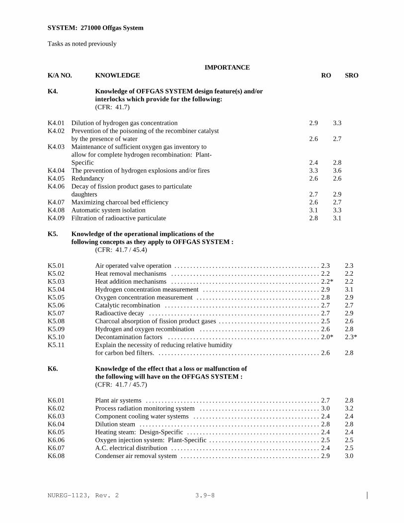
NUREG-1123, Rev. 2 |3.9-8
SYSTEM: 271000 Offgas System
Tasks as noted previously
IMPORTANCE K/A NO. KNOWLEDGE RO SRO
K4. Knowledge of OFFGAS SYSTEM design feature(s) and/orinterlocks which provide for the following:(CFR: 41.7)
K4.01 Dilution of hydrogen gas concentration 2.9 3.3K4.02 Prevention of the poisoning of the recombiner catalyst
by the presence of water 2.6 2.7K4.03 Maintenance of sufficient oxygen gas inventory to
allow for complete hydrogen recombination: Plant-Specific 2.4 2.8
K4.04 The prevention of hydrogen explosions and/or fires 3.3 3.6K4.05 Redundancy 2.6 2.6K4.06 Decay of fission product gases to particulate
daughters 2.7 2.9K4.07 Maximizing charcoal bed efficiency 2.6 2.7K4.08 Automatic system isolation 3.1 3.3K4.09 Filtration of radioactive particulate 2.8 3.1
K5. Knowledge of the operational implications of thefollowing concepts as they apply to OFFGAS SYSTEM :
(CFR: 41.7 / 45.4)
K5.01 Air operated valve operation . . . . . . . . . . . . . . . . . . . . . . . . . . . . . . . . . . . . . . . . . . . . . . 2.3 2.3K5.02 Heat removal mechanisms . . . . . . . . . . . . . . . . . . . . . . . . . . . . . . . . . . . . . . . . . . . . . . . 2.2 2.2K5.03 Heat addition mechanisms . . . . . . . . . . . . . . . . . . . . . . . . . . . . . . . . . . . . . . . . . . . . . . . 2.2* 2.2K5.04 Hydrogen concentration measurement . . . . . . . . . . . . . . . . . . . . . . . . . . . . . . . . . . . . . 2.9 3.1K5.05 Oxygen concentration measurement . . . . . . . . . . . . . . . . . . . . . . . . . . . . . . . . . . . . . . . 2.8 2.9K5.06 Catalytic recombination . . . . . . . . . . . . . . . . . . . . . . . . . . . . . . . . . . . . . . . . . . . . . . . . . 2.7 2.7K5.07 Radioactive decay . . . . . . . . . . . . . . . . . . . . . . . . . . . . . . . . . . . . . . . . . . . . . . . . . . . . . . 2.7 2.9K5.08 Charcoal absorption of fission product gases . . . . . . . . . . . . . . . . . . . . . . . . . . . . . . . . 2.5 2.6K5.09 Hydrogen and oxygen recombination . . . . . . . . . . . . . . . . . . . . . . . . . . . . . . . . . . . . . . 2.6 2.8K5.10 Decontamination factors . . . . . . . . . . . . . . . . . . . . . . . . . . . . . . . . . . . . . . . . . . . . . . . . 2.0* 2.3*K5.11 Explain the necessity of reducing relative humidity
for carbon bed filters. . . . . . . . . . . . . . . . . . . . . . . . . . . . . . . . . . . . . . . . . . . . . . . . . . . . 2.6 2.8
K6. Knowledge of the effect that a loss or malfunction ofthe following will have on the OFFGAS SYSTEM :(CFR: 41.7 / 45.7)
K6.01 Plant air systems . . . . . . . . . . . . . . . . . . . . . . . . . . . . . . . . . . . . . . . . . . . . . . . . . . . . . . . 2.7 2.8K6.02 Process radiation monitoring system . . . . . . . . . . . . . . . . . . . . . . . . . . . . . . . . . . . . . . 3.0 3.2K6.03 Component cooling water systems . . . . . . . . . . . . . . . . . . . . . . . . . . . . . . . . . . . . . . . . 2.4 2.4K6.04 Dilution steam . . . . . . . . . . . . . . . . . . . . . . . . . . . . . . . . . . . . . . . . . . . . . . . . . . . . . . . . . 2.8 2.8K6.05 Heating steam: Design-Specific . . . . . . . . . . . . . . . . . . . . . . . . . . . . . . . . . . . . . . . . . . 2.4 2.4K6.06 Oxygen injection system: Plant-Specific . . . . . . . . . . . . . . . . . . . . . . . . . . . . . . . . . . . 2.5 2.5K6.07 A.C. electrical distribution . . . . . . . . . . . . . . . . . . . . . . . . . . . . . . . . . . . . . . . . . . . . . . . 2.4 2.5K6.08 Condenser air removal system . . . . . . . . . . . . . . . . . . . . . . . . . . . . . . . . . . . . . . . . . . . . 2.9 3.0

NUREG-1123, Rev. 2 |3.9-9
SYSTEM: 271000 Offgas System
Tasks as noted previously
IMPORTANCE K/A NO. KNOWLEDGE RO SRO
K6.09 Fuel cladding integrity . . . . . . . . . . . . . . . . . . . . . . . . . . . . . . . . . . . . . . . . . . . . . . . . . . 3.4 3.6K6.10 Condensate system flow . . . . . . . . . . . . . . . . . . . . . . . . . . . . . . . . . . . . . . . . . . . . . . . . . 2.7 2.8K6.11 Condenser vacuum . . . . . . . . . . . . . . . . . . . . . . . . . . . . . . . . . . . . . . . . . . . . . . . . . . . . . . 3.2 3.3K6.12 Glycol system . . . . . . . . . . . . . . . . . . . . . . . . . . . . . . . . . . . . . . . . . . . . . . . . . . . . . . . . . 2.1* 2.2*K6.13 Plant exhaust: BWR-1 . . . . . . . . . . . . . . . . . . . . . . . . . . . . . . . . . . . . . . . . . . . . . . . . . . 3.0 3.4
ABILITY
A1. Ability to predict and/or monitor changes inparameters associated with operating the OFFGAS SYSTEMcontrols including:(CFR: 41.5 / 45.5)
A1.01 Condenser vacuum . . . . . . . . . . . . . . . . . . . . . . . . . . . . . . . . . . . . . . . . . . . . . . . . . . . . . . 3.3 3.2A1.02 Station radioactive release rate . . . . . . . . . . . . . . . . . . . . . . . . . . . . . . . . . . . . . . . . . . . 3.0 3.6A1.03 Preheater discharge temperature . . . . . . . . . . . . . . . . . . . . . . . . . . . . . . . . . . . . . . . . . . 2.2* 2.3A1.04 Recombiner catalyst temperature . . . . . . . . . . . . . . . . . . . . . . . . . . . . . . . . . . . . . . . . . 2.2* 2.4A1.05 Cooler condenser discharge temperature . . . . . . . . . . . . . . . . . . . . . . . . . . . . . . . . . . . 2.2* 2.4A1.06 Filter differential pressure . . . . . . . . . . . . . . . . . . . . . . . . . . . . . . . . . . . . . . . . . . . . . . . 2.4* 2.5A1.07 Charcoal bed humidity . . . . . . . . . . . . . . . . . . . . . . . . . . . . . . . . . . . . . . . . . . . . . . . . . . 2.4* 2.5A1.08 System flow . . . . . . . . . . . . . . . . . . . . . . . . . . . . . . . . . . . . . . . . . . . . . . . . . . . . . . . . . . . 3.1 3.1A1.09 Charcoal bed temperature . . . . . . . . . . . . . . . . . . . . . . . . . . . . . . . . . . . . . . . . . . . . . . . . 2.1* 2.4A1.10 Charcoal vault temperature . . . . . . . . . . . . . . . . . . . . . . . . . . . . . . . . . . . . . . . . . . . . . . . 2.3 2.5A1.11 Offgas condenser temperatures . . . . . . . . . . . . . . . . . . . . . . . . . . . . . . . . . . . . . . . . . . . 2.3 2.4A1.12 Process radiation monitoring indications . . . . . . . . . . . . . . . . . . . . . . . . . . . . . . . . . . . 3.1 3.5A1.13 Hydrogen gas concentration . . . . . . . . . . . . . . . . . . . . . . . . . . . . . . . . . . . . . . . . . . . . . . 3.2 3.7A1.14 Oxygen gas concentration . . . . . . . . . . . . . . . . . . . . . . . . . . . . . . . . . . . . . . . . . . . . . . . . 2.7 3.0A1.15 Steam supply pressures . . . . . . . . . . . . . . . . . . . . . . . . . . . . . . . . . . . . . . . . . . . . . . . . . . 2.7 2.8
A2. Ability to (a) predict the impacts of the following onthe OFFGAS SYSTEM ; and (b) based on thosepredictions, use procedures to correct, control, ormitigate the consequences of those abnormal conditionsor operations:(CFR: 41.5 / 45.6)
A2.01 Low condenser vacuum . . . . . . . . . . . . . . . . . . . . . . . . . . . . . . . . . . . . . . . . . . . . . . . . . . 3.1 3.3A2.02 Low dilution steam flow . . . . . . . . . . . . . . . . . . . . . . . . . . . . . . . . . . . . . . . . . . . . . . . . . 2.9 3.1A2.03 Main steamline high radiation . . . . . . . . . . . . . . . . . . . . . . . . . . . . . . . . . . . . . . . . . . . . 3.5 3.8A2.04 Offgas system high radiation . . . . . . . . . . . . . . . . . . . . . . . . . . . . . . . . . . . . . . . . . . . . . 3.7 4.1A2.05 High charcoal bed humidity . . . . . . . . . . . . . . . . . . . . . . . . . . . . . . . . . . . . . . . . . . . . . . 2.5 2.9A2.06 Offgas system holdup volume explosion/ fire . . . . . . . . . . . . . . . . . . . . . . . . . . . . . . . 3.5 3.9A2.07 Low oxygen injection flow: Plant-Specific . . . . . . . . . . . . . . . . . . . . . . . . . . . . . . . . . 2.7 3.3A2.08 A.C. distribution failures . . . . . . . . . . . . . . . . . . . . . . . . . . . . . . . . . . . . . . . . . . . . . . . . 2.5 2.7A2.09 Valve closures . . . . . . . . . . . . . . . . . . . . . . . . . . . . . . . . . . . . . . . . . . . . . . . . . . . . . . . . . 2.6 2.8A2.10 Offgas system high flow . . . . . . . . . . . . . . . . . . . . . . . . . . . . . . . . . . . . . . . . . . . . . . . . . 3.1 3.3A2.11 Offgas system low flow . . . . . . . . . . . . . . . . . . . . . . . . . . . . . . . . . . . . . . . . . . . . . . . . . 2.8 2.9

NUREG-1123, Rev. 2 |3.9-10
SYSTEM: 271000 Offgas System
Tasks as noted previously
IMPORTANCE K/A NO. ABILITY RO SRO
A2.12 Recombiner high temperature . . . . . . . . . . . . . . . . . . . . . . . . . . . . . . . . . . . . . . . . . . . . 2.7 2.9A2.13 Recombiner low temperature . . . . . . . . . . . . . . . . . . . . . . . . . . . . . . . . . . . . . . . . . . . . . 2.4 2.8A2.14 Offgas filter high differential pressure . . . . . . . . . . . . . . . . . . . . . . . . . . . . . . . . . . . . . 2.6 2.8A2.15 Air intrusion . . . . . . . . . . . . . . . . . . . . . . . . . . . . . . . . . . . . . . . . . . . . . . . . . . . . . . . . . . . 2.7 2.9A2.16 Loss of offgas system loop seals . . . . . . . . . . . . . . . . . . . . . . . . . . . . . . . . . . . . . . . . . . 2.9 3.2A2.17 Reactor power changes . . . . . . . . . . . . . . . . . . . . . . . . . . . . . . . . . . . . . . . . . . . . . . . . . . 2.9 3.1
A3. Ability to monitor automatic operations of the OFFGASSYSTEM including:(CFR: 41.7 / 45.7)
A3.01 Automatic system isolations . . . . . . . . . . . . . . . . . . . . . . . . . . . . . . . . . . . . . . . . . . . . . 3.3 3.3A3.02 System flows . . . . . . . . . . . . . . . . . . . . . . . . . . . . . . . . . . . . . . . . . . . . . . . . . . . . . . . . . . 2.9 2.8A3.03 System temperatures . . . . . . . . . . . . . . . . . . . . . . . . . . . . . . . . . . . . . . . . . . . . . . . . . . . . 2.8 2.8A3.04 †Station radioactive release rate: Plant-Specific . . . . . . . . . . . . . . . . . . . . . . . . . . . . 3.0 3.8A3.05 System indicating lights and alarms . . . . . . . . . . . . . . . . . . . . . . . . . . . . . . . . . . . . . . . . 2.9 2.9A3.06 System differential pressures . . . . . . . . . . . . . . . . . . . . . . . . . . . . . . . . . . . . . . . . . . . . . 2.5 2.5A3.07 †Process radiation monitoring system indications . . . . . . . . . . . . . . . . . . . . . . . . . . . 3.4 3.6
A4. Ability to manually operate and/or monitor in thecontrol room:(CFR: 41.7 / 45.5 to 45.8)
A4.01 Reset system isolations . . . . . . . . . . . . . . . . . . . . . . . . . . . . . . . . . . . . . . . . . . . . . . . . . 2.8 2.8A4.02 System flows . . . . . . . . . . . . . . . . . . . . . . . . . . . . . . . . . . . . . . . . . . . . . . . . . . . . . . . . . . 2.9 2.9A4.03 System temperatures . . . . . . . . . . . . . . . . . . . . . . . . . . . . . . . . . . . . . . . . . . . . . . . . . . . . 2.8 2.8A4.04 Condenser vacuum . . . . . . . . . . . . . . . . . . . . . . . . . . . . . . . . . . . . . . . . . . . . . . . . . . . . . . 3.4 3.5A4.05 Station radioactive release rate . . . . . . . . . . . . . . . . . . . . . . . . . . . . . . . . . . . . . . . . . . . 3.2 3.9A4.06 System indicating lights and alarms . . . . . . . . . . . . . . . . . . . . . . . . . . . . . . . . . . . . . . . . 3.3 3.2A4.07 System differential pressures . . . . . . . . . . . . . . . . . . . . . . . . . . . . . . . . . . . . . . . . . . . . . 2.4 2.5A4.08 Process radiation monitoring system . . . . . . . . . . . . . . . . . . . . . . . . . . . . . . . . . . . . . . 3.2 3.6A4.09 Offgas system controls/components . . . . . . . . . . . . . . . . . . . . . . . . . . . . . . . . . . . . . . . 3.3 3.2
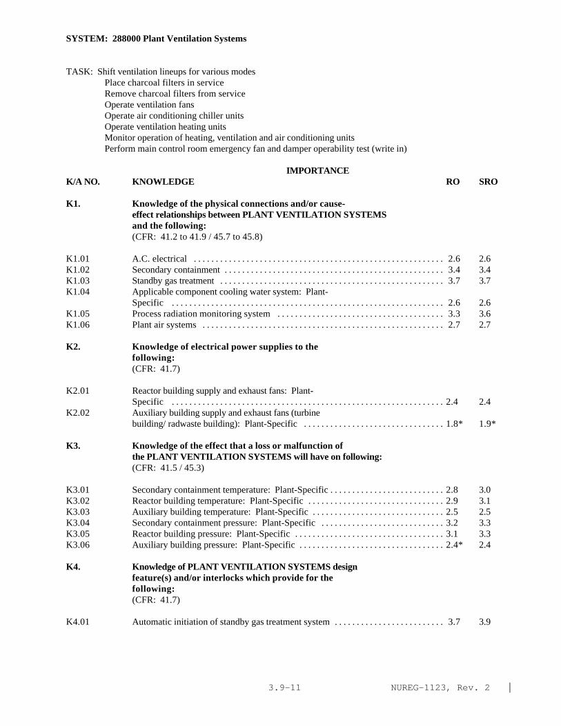
NUREG-1123, Rev. 2 |3.9-11
SYSTEM: 288000 Plant Ventilation Systems
TASK: Shift ventilation lineups for various modes Place charcoal filters in service Remove charcoal filters from service Operate ventilation fans Operate air conditioning chiller units Operate ventilation heating units Monitor operation of heating, ventilation and air conditioning unitsPerform main control room emergency fan and damper operability test (write in)
IMPORTANCE K/A NO. KNOWLEDGE RO SRO
K1. Knowledge of the physical connections and/or cause-effect relationships between PLANT VENTILATION SYSTEMSand the following:(CFR: 41.2 to 41.9 / 45.7 to 45.8)
K1.01 A.C. electrical . . . . . . . . . . . . . . . . . . . . . . . . . . . . . . . . . . . . . . . . . . . . . . . . . . . . . . . . . 2.6 2.6K1.02 Secondary containment . . . . . . . . . . . . . . . . . . . . . . . . . . . . . . . . . . . . . . . . . . . . . . . . . . 3.4 3.4K1.03 Standby gas treatment . . . . . . . . . . . . . . . . . . . . . . . . . . . . . . . . . . . . . . . . . . . . . . . . . . . 3.7 3.7K1.04 Applicable component cooling water system: Plant-
Specific . . . . . . . . . . . . . . . . . . . . . . . . . . . . . . . . . . . . . . . . . . . . . . . . . . . . . . . . . . . . . . 2.6 2.6K1.05 Process radiation monitoring system . . . . . . . . . . . . . . . . . . . . . . . . . . . . . . . . . . . . . . 3.3 3.6K1.06 Plant air systems . . . . . . . . . . . . . . . . . . . . . . . . . . . . . . . . . . . . . . . . . . . . . . . . . . . . . . . 2.7 2.7
K2. Knowledge of electrical power supplies to thefollowing:(CFR: 41.7)
K2.01 Reactor building supply and exhaust fans: Plant-Specific . . . . . . . . . . . . . . . . . . . . . . . . . . . . . . . . . . . . . . . . . . . . . . . . . . . . . . . . . . . . . . 2.4 2.4
K2.02 Auxiliary building supply and exhaust fans (turbinebuilding/ radwaste building): Plant-Specific . . . . . . . . . . . . . . . . . . . . . . . . . . . . . . . . 1.8* 1.9*
K3. Knowledge of the effect that a loss or malfunction ofthe PLANT VENTILATION SYSTEMS will have on following:(CFR: 41.5 / 45.3)
K3.01 Secondary containment temperature: Plant-Specific . . . . . . . . . . . . . . . . . . . . . . . . . . 2.8 3.0K3.02 Reactor building temperature: Plant-Specific . . . . . . . . . . . . . . . . . . . . . . . . . . . . . . . 2.9 3.1K3.03 Auxiliary building temperature: Plant-Specific . . . . . . . . . . . . . . . . . . . . . . . . . . . . . . 2.5 2.5K3.04 Secondary containment pressure: Plant-Specific . . . . . . . . . . . . . . . . . . . . . . . . . . . . 3.2 3.3K3.05 Reactor building pressure: Plant-Specific . . . . . . . . . . . . . . . . . . . . . . . . . . . . . . . . . . 3.1 3.3K3.06 Auxiliary building pressure: Plant-Specific . . . . . . . . . . . . . . . . . . . . . . . . . . . . . . . . . 2.4* 2.4
K4. Knowledge of PLANT VENTILATION SYSTEMS designfeature(s) and/or interlocks which provide for thefollowing:(CFR: 41.7)
K4.01 Automatic initiation of standby gas treatment system . . . . . . . . . . . . . . . . . . . . . . . . . 3.7 3.9
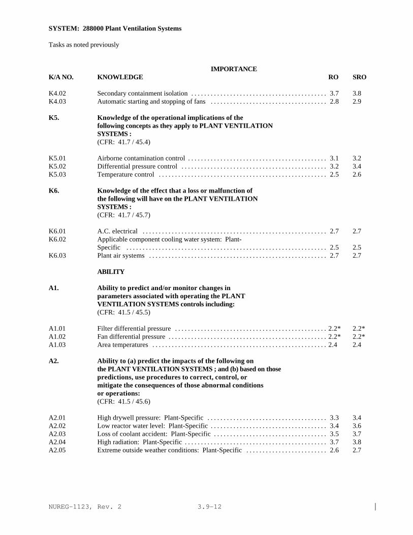
NUREG-1123, Rev. 2 |3.9-12
SYSTEM: 288000 Plant Ventilation Systems
Tasks as noted previously
IMPORTANCE K/A NO. KNOWLEDGE RO SRO
K4.02 Secondary containment isolation . . . . . . . . . . . . . . . . . . . . . . . . . . . . . . . . . . . . . . . . . . 3.7 3.8K4.03 Automatic starting and stopping of fans . . . . . . . . . . . . . . . . . . . . . . . . . . . . . . . . . . . . 2.8 2.9
K5. Knowledge of the operational implications of thefollowing concepts as they apply to PLANT VENTILATIONSYSTEMS :(CFR: 41.7 / 45.4)
K5.01 Airborne contamination control . . . . . . . . . . . . . . . . . . . . . . . . . . . . . . . . . . . . . . . . . . . 3.1 3.2K5.02 Differential pressure control . . . . . . . . . . . . . . . . . . . . . . . . . . . . . . . . . . . . . . . . . . . . . 3.2 3.4K5.03 Temperature control . . . . . . . . . . . . . . . . . . . . . . . . . . . . . . . . . . . . . . . . . . . . . . . . . . . . 2.5 2.6
K6. Knowledge of the effect that a loss or malfunction ofthe following will have on the PLANT VENTILATIONSYSTEMS :(CFR: 41.7 / 45.7)
K6.01 A.C. electrical . . . . . . . . . . . . . . . . . . . . . . . . . . . . . . . . . . . . . . . . . . . . . . . . . . . . . . . . . 2.7 2.7K6.02 Applicable component cooling water system: Plant-
Specific . . . . . . . . . . . . . . . . . . . . . . . . . . . . . . . . . . . . . . . . . . . . . . . . . . . . . . . . . . . . . . 2.5 2.5K6.03 Plant air systems . . . . . . . . . . . . . . . . . . . . . . . . . . . . . . . . . . . . . . . . . . . . . . . . . . . . . . . 2.7 2.7
ABILITY
A1. Ability to predict and/or monitor changes inparameters associated with operating the PLANTVENTILATION SYSTEMS controls including:(CFR: 41.5 / 45.5)
A1.01 Filter differential pressure . . . . . . . . . . . . . . . . . . . . . . . . . . . . . . . . . . . . . . . . . . . . . . . 2.2* 2.2*A1.02 Fan differential pressure . . . . . . . . . . . . . . . . . . . . . . . . . . . . . . . . . . . . . . . . . . . . . . . . . 2.2* 2.2*A1.03 Area temperatures . . . . . . . . . . . . . . . . . . . . . . . . . . . . . . . . . . . . . . . . . . . . . . . . . . . . . . 2.4 2.4
A2. Ability to (a) predict the impacts of the following onthe PLANT VENTILATION SYSTEMS ; and (b) based on thosepredictions, use procedures to correct, control, ormitigate the consequences of those abnormal conditionsor operations:(CFR: 41.5 / 45.6)
A2.01 High drywell pressure: Plant-Specific . . . . . . . . . . . . . . . . . . . . . . . . . . . . . . . . . . . . . 3.3 3.4A2.02 Low reactor water level: Plant-Specific . . . . . . . . . . . . . . . . . . . . . . . . . . . . . . . . . . . . 3.4 3.6A2.03 Loss of coolant accident: Plant-Specific . . . . . . . . . . . . . . . . . . . . . . . . . . . . . . . . . . . 3.5 3.7A2.04 High radiation: Plant-Specific . . . . . . . . . . . . . . . . . . . . . . . . . . . . . . . . . . . . . . . . . . . . 3.7 3.8A2.05 Extreme outside weather conditions: Plant-Specific . . . . . . . . . . . . . . . . . . . . . . . . . 2.6 2.7

NUREG-1123, Rev. 2 |3.9-13
SYSTEM: 288000 Plant Ventilation Systems
Tasks as noted previously
IMPORTANCE K/A NO. KNOWLEDGE RO SRO
A3. Ability to monitor automatic operations of the PLANTVENTILATION SYSTEMS including:(CFR: 41.7 / 45.7)
A3.01 Isolation/initiation signals . . . . . . . . . . . . . . . . . . . . . . . . . . . . . . . . . . . . . . . . . . . . . . . 3.8 3.8
A4. Ability to manually operate and/or monitor in thecontrol room:
A4.01 Start and stop fans . . . . . . . . . . . . . . . . . . . . . . . . . . . . . . . . . . . . . . . . . . . . . . . . . . . . . . 3.1 2.9A4.02 Area temperature . . . . . . . . . . . . . . . . . . . . . . . . . . . . . . . . . . . . . . . . . . . . . . . . . . . . . . . 2.8 2.8

NUREG-1123, Rev. 2 |3.9-14
SYSTEM: 272000 Radiation Monitoring System
TASK: Perform lineups of the area radiation monitoring systemOperate area radiation monitorsMonitor area radiationPerform lineups of process radiation monitoring systemOperate process radiation monitorsMonitor process radiation monitor operation
IMPORTANCE K/A NO. KNOWLEDGE RO SRO
K1. Knowledge of the physical connections and/or cause-effect relationships between RADIATION MONITORINGSYSTEM and the following:(CFR: 41.2 to 41.9 / 45.7 to 45.8)
K1.01 Main steam system . . . . . . . . . . . . . . . . . . . . . . . . . . . . . . . . . . . . . . . . . . . . . . . . . . . . . 3.6 3.8K1.02 Offgas system (augmented offgas): Plant-Specific . . . . . . . . . . . . . . . . . . . . . . . . . . 3.2 3.5K1.03 Stack gas: Plant-Specific . . . . . . . . . . . . . . . . . . . . . . . . . . . . . . . . . . . . . . . . . . . . . . . . 3.3 3.6K1.04 Applicable component cooling water system . . . . . . . . . . . . . . . . . . . . . . . . . . . . . . . . 2.9 2.9K1.05 Radwaste system . . . . . . . . . . . . . . . . . . . . . . . . . . . . . . . . . . . . . . . . . . . . . . . . . . . . . . . 2.8 3.1|K1.06 Reactor building ventilation system: Plant-Specific . . . . . . . . . . . . . . . . . . . . . . . . . . 3.2 3.3K1.07 Isolation condenser: Plant-Specific . . . . . . . . . . . . . . . . . . . . . . . . . . . . . . . . . . . . . . . 3.0 3.2K1.08 Reactor protection system . . . . . . . . . . . . . . . . . . . . . . . . . . . . . . . . . . . . . . . . . . . . . . . 3.6 3.9K1.09 Primary containment isolation system . . . . . . . . . . . . . . . . . . . . . . . . . . . . . . . . . . . . . 3.6 3.8K1.10 Reactor building refuel floor: Plant-Specific . . . . . . . . . . . . . . . . . . . . . . . . . . . . . . . 3.4 3.6K1.11 Reactor building overhead crane; Plant-Specific . . . . . . . . . . . . . . . . . . . . . . . . . . . . . 2.1* 2.4*K1.12 Reactor building . . . . . . . . . . . . . . . . . . . . . . . . . . . . . . . . . . . . . . . . . . . . . . . . . . . . . . . . 3.1 3.2K1.13 Turbine building . . . . . . . . . . . . . . . . . . . . . . . . . . . . . . . . . . . . . . . . . . . . . . . . . . . . . . . . 2.9 3.0K1.14 Radwaste building: Plant-Specific . . . . . . . . . . . . . . . . . . . . . . . . . . . . . . . . . . . . . . . . 2.7 2.8K1.15 Filter building: Plant-Specific . . . . . . . . . . . . . . . . . . . . . . . . . . . . . . . . . . . . . . . . . . . . 2.8 3.0K1.16 Process computer . . . . . . . . . . . . . . . . . . . . . . . . . . . . . . . . . . . . . . . . . . . . . . . . . . . . . . . 2.2* 2.3*K1.17 SPDS/ERIS/CRIDS/GDS: Plant-Specific . . . . . . . . . . . . . . . . . . . . . . . . . . . . . . . . . . 2.4 2.7K1.18 Primary containment/containment building: Plant-
Specific . . . . . . . . . . . . . . . . . . . . . . . . . . . . . . . . . . . . . . . . . . . . . . . . . . . . . . . . . . . . . . 3.1 3.1K1.19 Drywell . . . . . . . . . . . . . . . . . . . . . . . . . . . . . . . . . . . . . . . . . . . . . . . . . . . . . . . . . . . . . . . 3.1 3.2K1.20 †Auxiliary building: Plant-Specific . . . . . . . . . . . . . . . . . . . . . . . . . . . . . . . . . . . . . . . 2.8 3.0K1.21 Circulating water: Plant-Specific . . . . . . . . . . . . . . . . . . . . . . . . . . . . . . . . . . . . . . . . . 2.3 2.4K1.22 Fuel building: mark-III . . . . . . . . . . . . . . . . . . . . . . . . . . . . . . . . . . . . . . . . . . . . . . . . . . 3.0 3.4K1.23 Continuous air monitoring: Plant-Specific . . . . . . . . . . . . . . . . . . . . . . . . . . . . . . . . . 3.0 3.3
K2. Knowledge of electrical power supplies to thefollowing:(CFR: 41.7)
K2.01 Main steamline radiation monitors . . . . . . . . . . . . . . . . . . . . . . . . . . . . . . . . . . . . . . . . . 2.5 2.8K2.02 Offgas radiation monitoring system . . . . . . . . . . . . . . . . . . . . . . . . . . . . . . . . . . . . . . . . 2.5 2.8K2.03 Stack gas radiation monitoring system . . . . . . . . . . . . . . . . . . . . . . . . . . . . . . . . . . . . . 2.5 2.8K2.04 Process liquid radiation monitoring system . . . . . . . . . . . . . . . . . . . . . . . . . . . . . . . . . 2.3 2.5

NUREG-1123, Rev. 2 |3.9-15
SYSTEM: 272000 Radiation Monitoring System
Tasks as noted previously
IMPORTANCE K/A NO. KNOWLEDGE RO SRO
K2.05 Reactor building ventilation monitors: Plant-Specific. . . . . . . . . . . . . . . . . . . . . . . . . . . . . . . . . . . . . . . . . . . . . . . . . . . . . . . . . . . . . . . . . . . . . . 2.6 2.9
K2.06 Area radiation monitors . . . . . . . . . . . . . . . . . . . . . . . . . . . . . . . . . . . . . . . . . . . . . . . . . 2.1* 2.2*K2.07 Control room ventilation monitors: Plant-Specific . . . . . . . . . . . . . . . . . . . . . . . . . . 2.2* 2.4*
K3 Knowledge of the effect that a loss or malfunction ofthe RADIATION MONITORING System will have onfollowing:(CFR: 41.5 / 45.3)
K3.01 †Station liquid effluent release monitoring . . . . . . . . . . . . . . . . . . . . . . . . . . . . . . . . . 3.2 3.8K3.02 †Station gaseous effluent release monitoring . . . . . . . . . . . . . . . . . . . . . . . . . . . . . . . 3.1 3.8K3.03 Station area radiation monitoring . . . . . . . . . . . . . . . . . . . . . . . . . . . . . . . . . . . . . . . . . . 3.2 3.4K3.04 Main steam system . . . . . . . . . . . . . . . . . . . . . . . . . . . . . . . . . . . . . . . . . . . . . . . . . . . . . 3.7 3.8K3.05 Offgas system . . . . . . . . . . . . . . . . . . . . . . . . . . . . . . . . . . . . . . . . . . . . . . . . . . . . . . . . . 3.5 3.7K3.06 Reactor building ventilation: Plant-Specific . . . . . . . . . . . . . . . . . . . . . . . . . . . . . . . . 3.4 3.6K3.07 Reactor building overhead crane operation: Plant-
Specific . . . . . . . . . . . . . . . . . . . . . . . . . . . . . . . . . . . . . . . . . . . . . . . . . . . . . . . . . . . . . . 2.4* 3.0K3.08 †Auxiliary building ventilation: Plant-Specific . . . . . . . . . . . . . . . . . . . . . . . . . . . . . . 2.9 3.3K3.09 Radwaste building ventilation: Plant-Specific . . . . . . . . . . . . . . . . . . . . . . . . . . . . . . . 2.8 3.1K3.10 Control room ventilation: Plant-Specific . . . . . . . . . . . . . . . . . . . . . . . . . . . . . . . . . . 2.9 3.3
K4. Knowledge of RADIATION MONITORING System designfeature(s) and/or interlocks which provide for thefollowing:(CFR: 41.7)
K4.01 Redundancy . . . . . . . . . . . . . . . . . . . . . . . . . . . . . . . . . . . . . . . . . . . . . . . . . . . . . . . . . . . 2.7 2.8K4.02 Automatic actions to contain the radioactive release
in the event that the predetermined release rates areexceeded . . . . . . . . . . . . . . . . . . . . . . . . . . . . . . . . . . . . . . . . . . . . . . . . . . . . . . . . . . . . . . 3.7 4.1
K4.03 Fail safe tripping of process radiation monitoringlogic during conditions of instrument failure . . . . . . . . . . . . . . . . . . . . . . . . . . . . . . . . 3.6 3.9
K5. Knowledge of the operational implications of thefollowing concepts as they apply to RADIATIONMONITORING SYSTEM :(CFR: 41.7 / 45.4)
K5.01 Hydrogen injection operation's effect on processradiation indications: Plant-Specific . . . . . . . . . . . . . . . . . . . . . . . . . . . . . . . . . . . . . . 3.2 3.5
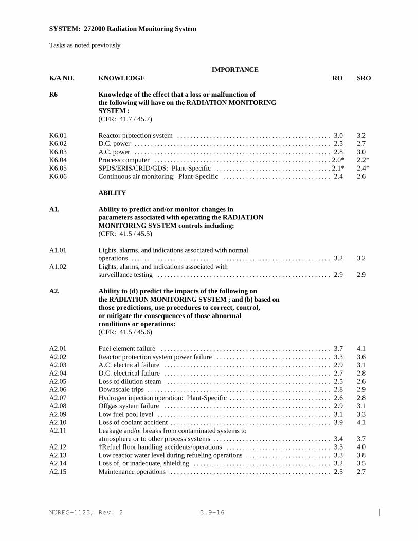
NUREG-1123, Rev. 2 |3.9-16
SYSTEM: 272000 Radiation Monitoring System
Tasks as noted previously
IMPORTANCE K/A NO. KNOWLEDGE RO SRO
K6 Knowledge of the effect that a loss or malfunction ofthe following will have on the RADIATION MONITORINGSYSTEM :(CFR: 41.7 / 45.7)
K6.01 Reactor protection system . . . . . . . . . . . . . . . . . . . . . . . . . . . . . . . . . . . . . . . . . . . . . . . 3.0 3.2K6.02 D.C. power . . . . . . . . . . . . . . . . . . . . . . . . . . . . . . . . . . . . . . . . . . . . . . . . . . . . . . . . . . . . 2.5 2.7K6.03 A.C. power . . . . . . . . . . . . . . . . . . . . . . . . . . . . . . . . . . . . . . . . . . . . . . . . . . . . . . . . . . . . 2.8 3.0K6.04 Process computer . . . . . . . . . . . . . . . . . . . . . . . . . . . . . . . . . . . . . . . . . . . . . . . . . . . . . . 2.0* 2.2*K6.05 SPDS/ERIS/CRID/GDS: Plant-Specific . . . . . . . . . . . . . . . . . . . . . . . . . . . . . . . . . . . 2.1* 2.4*K6.06 Continuous air monitoring: Plant-Specific . . . . . . . . . . . . . . . . . . . . . . . . . . . . . . . . . 2.4 2.6
ABILITY
A1. Ability to predict and/or monitor changes inparameters associated with operating the RADIATIONMONITORING SYSTEM controls including:(CFR: 41.5 / 45.5)
A1.01 Lights, alarms, and indications associated with normaloperations . . . . . . . . . . . . . . . . . . . . . . . . . . . . . . . . . . . . . . . . . . . . . . . . . . . . . . . . . . . . . 3.2 3.2
A1.02 Lights, alarms, and indications associated withsurveillance testing . . . . . . . . . . . . . . . . . . . . . . . . . . . . . . . . . . . . . . . . . . . . . . . . . . . . . 2.9 2.9
A2. Ability to (d) predict the impacts of the following onthe RADIATION MONITORING SYSTEM ; and (b) based onthose predictions, use procedures to correct, control,or mitigate the consequences of those abnormalconditions or operations:(CFR: 41.5 / 45.6)
A2.01 Fuel element failure . . . . . . . . . . . . . . . . . . . . . . . . . . . . . . . . . . . . . . . . . . . . . . . . . . . . 3.7 4.1A2.02 Reactor protection system power failure . . . . . . . . . . . . . . . . . . . . . . . . . . . . . . . . . . . 3.3 3.6A2.03 A.C. electrical failure . . . . . . . . . . . . . . . . . . . . . . . . . . . . . . . . . . . . . . . . . . . . . . . . . . . 2.9 3.1A2.04 D.C. electrical failure . . . . . . . . . . . . . . . . . . . . . . . . . . . . . . . . . . . . . . . . . . . . . . . . . . . 2.7 2.8A2.05 Loss of dilution steam . . . . . . . . . . . . . . . . . . . . . . . . . . . . . . . . . . . . . . . . . . . . . . . . . . 2.5 2.6A2.06 Downscale trips . . . . . . . . . . . . . . . . . . . . . . . . . . . . . . . . . . . . . . . . . . . . . . . . . . . . . . . . 2.8 2.9A2.07 Hydrogen injection operation: Plant-Specific . . . . . . . . . . . . . . . . . . . . . . . . . . . . . . . 2.6 2.8A2.08 Offgas system failure . . . . . . . . . . . . . . . . . . . . . . . . . . . . . . . . . . . . . . . . . . . . . . . . . . . 2.9 3.1A2.09 Low fuel pool level . . . . . . . . . . . . . . . . . . . . . . . . . . . . . . . . . . . . . . . . . . . . . . . . . . . . . 3.1 3.3A2.10 Loss of coolant accident . . . . . . . . . . . . . . . . . . . . . . . . . . . . . . . . . . . . . . . . . . . . . . . . . 3.9 4.1A2.11 Leakage and/or breaks from contaminated systems to
atmosphere or to other process systems . . . . . . . . . . . . . . . . . . . . . . . . . . . . . . . . . . . . 3.4 3.7A2.12 †Refuel floor handling accidents/operations . . . . . . . . . . . . . . . . . . . . . . . . . . . . . . . . 3.3 4.0A2.13 Low reactor water level during refueling operations . . . . . . . . . . . . . . . . . . . . . . . . . . 3.3 3.8A2.14 Loss of, or inadequate, shielding . . . . . . . . . . . . . . . . . . . . . . . . . . . . . . . . . . . . . . . . . . 3.2 3.5A2.15 Maintenance operations . . . . . . . . . . . . . . . . . . . . . . . . . . . . . . . . . . . . . . . . . . . . . . . . . 2.5 2.7
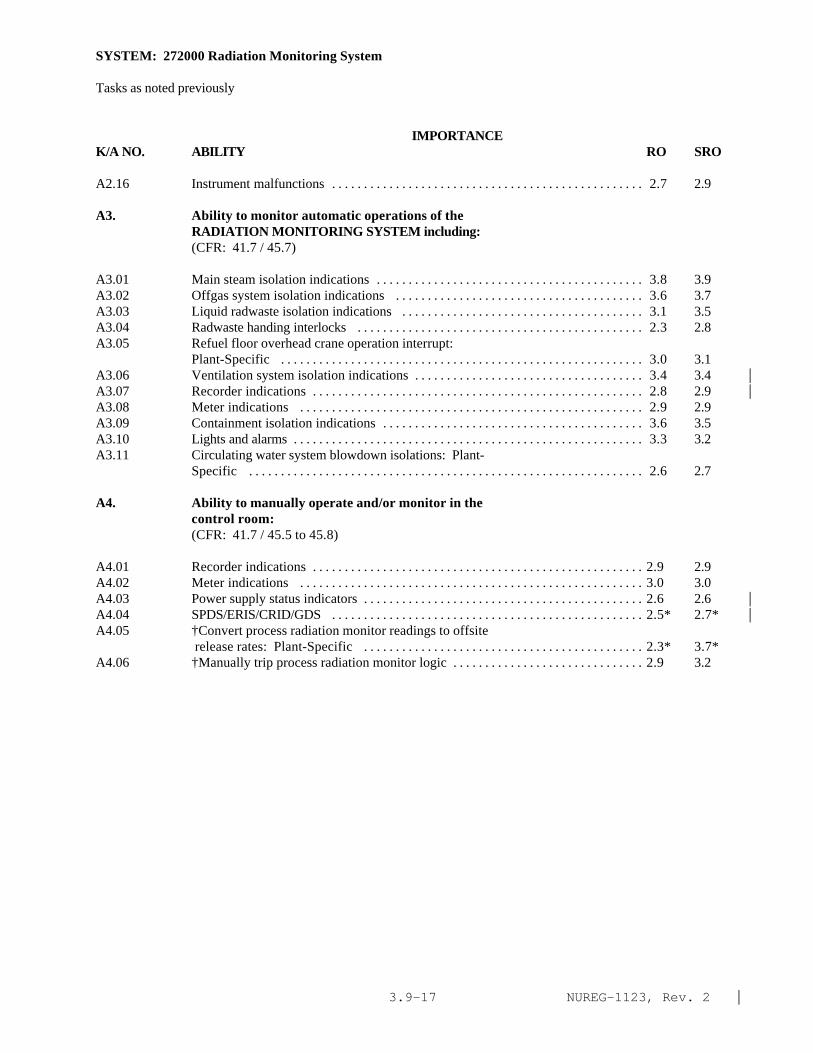
NUREG-1123, Rev. 2 |3.9-17
SYSTEM: 272000 Radiation Monitoring System
Tasks as noted previously
IMPORTANCE K/A NO. ABILITY RO SRO
A2.16 Instrument malfunctions . . . . . . . . . . . . . . . . . . . . . . . . . . . . . . . . . . . . . . . . . . . . . . . . . 2.7 2.9
A3. Ability to monitor automatic operations of theRADIATION MONITORING SYSTEM including:(CFR: 41.7 / 45.7)
A3.01 Main steam isolation indications . . . . . . . . . . . . . . . . . . . . . . . . . . . . . . . . . . . . . . . . . . 3.8 3.9A3.02 Offgas system isolation indications . . . . . . . . . . . . . . . . . . . . . . . . . . . . . . . . . . . . . . . 3.6 3.7A3.03 Liquid radwaste isolation indications . . . . . . . . . . . . . . . . . . . . . . . . . . . . . . . . . . . . . . 3.1 3.5A3.04 Radwaste handing interlocks . . . . . . . . . . . . . . . . . . . . . . . . . . . . . . . . . . . . . . . . . . . . . 2.3 2.8A3.05 Refuel floor overhead crane operation interrupt:
Plant-Specific . . . . . . . . . . . . . . . . . . . . . . . . . . . . . . . . . . . . . . . . . . . . . . . . . . . . . . . . . 3.0 3.1A3.06 Ventilation system isolation indications . . . . . . . . . . . . . . . . . . . . . . . . . . . . . . . . . . . . 3.4 3.4 |A3.07 Recorder indications . . . . . . . . . . . . . . . . . . . . . . . . . . . . . . . . . . . . . . . . . . . . . . . . . . . . 2.8 2.9 |A3.08 Meter indications . . . . . . . . . . . . . . . . . . . . . . . . . . . . . . . . . . . . . . . . . . . . . . . . . . . . . . 2.9 2.9A3.09 Containment isolation indications . . . . . . . . . . . . . . . . . . . . . . . . . . . . . . . . . . . . . . . . . 3.6 3.5A3.10 Lights and alarms . . . . . . . . . . . . . . . . . . . . . . . . . . . . . . . . . . . . . . . . . . . . . . . . . . . . . . . 3.3 3.2A3.11 Circulating water system blowdown isolations: Plant-
Specific . . . . . . . . . . . . . . . . . . . . . . . . . . . . . . . . . . . . . . . . . . . . . . . . . . . . . . . . . . . . . . 2.6 2.7
A4. Ability to manually operate and/or monitor in thecontrol room:(CFR: 41.7 / 45.5 to 45.8)
A4.01 Recorder indications . . . . . . . . . . . . . . . . . . . . . . . . . . . . . . . . . . . . . . . . . . . . . . . . . . . . 2.9 2.9A4.02 Meter indications . . . . . . . . . . . . . . . . . . . . . . . . . . . . . . . . . . . . . . . . . . . . . . . . . . . . . . 3.0 3.0A4.03 Power supply status indicators . . . . . . . . . . . . . . . . . . . . . . . . . . . . . . . . . . . . . . . . . . . . 2.6 2.6 |A4.04 SPDS/ERIS/CRID/GDS . . . . . . . . . . . . . . . . . . . . . . . . . . . . . . . . . . . . . . . . . . . . . . . . . 2.5* 2.7* |A4.05 †Convert process radiation monitor readings to offsite
release rates: Plant-Specific . . . . . . . . . . . . . . . . . . . . . . . . . . . . . . . . . . . . . . . . . . . . 2.3* 3.7*A4.06 †Manually trip process radiation monitor logic . . . . . . . . . . . . . . . . . . . . . . . . . . . . . . 2.9 3.2

NUREG-1123, Rev. 2 |3.9-18
SYSTEM: 268000 Radwaste
TASK: Monitor the liquid radwaste system (write in)Operate the discharge water floor drain system (write in)Operate the drywell equipment drain pump (write in)Monitor the liquid radwaste system (waste collection) (write in)Startup a concentrator/evaporatorSecure a concentrator/evaporatorPerform lineups on the solid radwaste system
IMPORTANCE K/A NO. KNOWLEDGE RO SRO
K1. Knowledge of the physical connections and/or cause-effect relationships between RADWASTE and thefollowing:(CFR: 41.2 to 41.9 / 45.7 to 45.8)
K1.01 Condensate system . . . . . . . . . . . . . . . . . . . . . . . . . . . . . . . . . . . . . . . . . . . . . . . . . . . . . . 2.2 2.6K1.02 Plant air systems . . . . . . . . . . . . . . . . . . . . . . . . . . . . . . . . . . . . . . . . . . . . . . . . . . . . . . . . 2.1* 2.4K1.03 Reactor building equipment drains: Plant-Specific . . . . . . . . . . . . . . . . . . . . . . . . . . . 2.6 2.9K1.04 Reactor building floor drains: Plant-Specific . . . . . . . . . . . . . . . . . . . . . . . . . . . . . . . . 2.7 2.9K1.05 Drywell equipment drains . . . . . . . . . . . . . . . . . . . . . . . . . . . . . . . . . . . . . . . . . . . . . . . . 2.9 3.2K1.06 Drywell floor drains . . . . . . . . . . . . . . . . . . . . . . . . . . . . . . . . . . . . . . . . . . . . . . . . . . . . . 2.9 3.2K1.07 Reactor water cleanup . . . . . . . . . . . . . . . . . . . . . . . . . . . . . . . . . . . . . . . . . . . . . . . . . . . 2.8 2.9K1.08 Fuel pool . . . . . . . . . . . . . . . . . . . . . . . . . . . . . . . . . . . . . . . . . . . . . . . . . . . . . . . . . . . . . . 2.7 2.8K1.09 ECCS systems . . . . . . . . . . . . . . . . . . . . . . . . . . . . . . . . . . . . . . . . . . . . . . . . . . . . . . . . . . 2.6 2.8K1.10 Auxiliary steam: Plant-Specific . . . . . . . . . . . . . . . . . . . . . . . . . . . . . . . . . . . . . . . . . . . 2.2 2.4K1.11 Applicable component cooling water system . . . . . . . . . . . . . . . . . . . . . . . . . . . . . . . . 2.2 2.4K1.12 Suppression pool . . . . . . . . . . . . . . . . . . . . . . . . . . . . . . . . . . . . . . . . . . . . . . . . . . . . . . . 2.3 2.5K1.13 Auxiliary building floor drains: Plant-Specific . . . . . . . . . . . . . . . . . . . . . . . . . . . . . . 2.2 2.4K1.14 Auxiliary building equipment drains: Plant-Specific . . . . . . . . . . . . . . . . . . . . . . . . . . 2.0* 2.2K1.15 Offgas system . . . . . . . . . . . . . . . . . . . . . . . . . . . . . . . . . . . . . . . . . . . . . . . . . . . . . . . . . . 2.3 2.5K1.16 Circulating water system: Plant-Specific . . . . . . . . . . . . . . . . . . . . . . . . . . . . . . . . . . . 2.3 2.5
K2. Knowledge of electrical power supplies to thefollowing:(CFR: 41.7)
None|
K3. Knowledge of the effect that a loss or malfunction ofthe RADWASTE will have on following:(CFR: 41.5 / 45.3)
K3.01 RWCU system . . . . . . . . . . . . . . . . . . . . . . . . . . . . . . . . . . . . . . . . . . . . . . . . . . . . . . . . . 2.4 2.5K3.02 Condensate system . . . . . . . . . . . . . . . . . . . . . . . . . . . . . . . . . . . . . . . . . . . . . . . . . . . . . . 2.2 2.4K3.03 ECCS systems . . . . . . . . . . . . . . . . . . . . . . . . . . . . . . . . . . . . . . . . . . . . . . . . . . . . . . . . . 2.2* 2.4K3.04 Drain sumps . . . . . . . . . . . . . . . . . . . . . . . . . . . . . . . . . . . . . . . . . . . . . . . . . . . . . . . . . . . 2.7 2.8K3.05 Fuel pools: Plant-Specific . . . . . . . . . . . . . . . . . . . . . . . . . . . . . . . . . . . . . . . . . . . . . . . 2.1 2.4

NUREG-1123, Rev. 2 |3.9-19
SYSTEM: 268000 Radwaste
Tasks as noted previously
IMPORTANCE K/A NO. KNOWLEDGE RO SRO
K4. Knowledge of RADWASTE design feature(s) and/orinterlocks which provide for the following:(CFR: 41.7)
None |
K5. Knowledge of the operational implications of thefollowing concepts as they apply to RADWASTE :(CFR: 41.5 / 45.3)
K5.01 Units of radiation, dose and dose rate . . . . . . . . . . . . . . . . . . . . . . . . . . . . . . . . . . . . . . 2.7 3.0K5.02 Radiation hazards and ALARA concept . . . . . . . . . . . . . . . . . . . . . . . . . . . . . . . . . . . . . 3.1 3.6*
K6. Knowledge of the effect that a loss or malfunction ofthe following will have on the RADWASTE :(CFR: 41.7)
K6.01 Applicable component cooling water system . . . . . . . . . . . . . . . . . . . . . . . . . . . . . . . . 2.2 2.5K6.02 Plant air systems . . . . . . . . . . . . . . . . . . . . . . . . . . . . . . . . . . . . . . . . . . . . . . . . . . . . . . . . 2.3 2.6K6.03 Building ventilation . . . . . . . . . . . . . . . . . . . . . . . . . . . . . . . . . . . . . . . . . . . . . . . . . . . . . 2.4 2.7K6.04 Circulating water . . . . . . . . . . . . . . . . . . . . . . . . . . . . . . . . . . . . . . . . . . . . . . . . . . . . . . . 2.1* 2.3
ABILITY
A1. Ability to predict and/or monitor changes inparameters associated with operating the RADWASTEcontrols including:(CFR: 41.5 / 45.5)
A1.01 Radiation level . . . . . . . . . . . . . . . . . . . . . . . . . . . . . . . . . . . . . . . . . . . . . . . . . . . . . . . . . 2.7* 3.1*A1.02 †Off-site release . . . . . . . . . . . . . . . . . . . . . . . . . . . . . . . . . . . . . . . . . . . . . . . . . . . . . . . 2.6* 3.6*
A2. Ability to (a) predict the impacts of the following onthe RADWASTE ; and (b) based on those predictions, useprocedures to correct, control, or mitigate theconsequences of those abnormal conditions oroperations:(CFR: 41.5 / 45.6)
A2.01 System rupture . . . . . . . . . . . . . . . . . . . . . . . . . . . . . . . . . . . . . . . . . . . . . . . . . . . . . . . . . 2.9 3.5A2.02 High turbidity water . . . . . . . . . . . . . . . . . . . . . . . . . . . . . . . . . . . . . . . . . . . . . . . . . . . . . 2.3 2.7A2.03 Loss of steam supply . . . . . . . . . . . . . . . . . . . . . . . . . . . . . . . . . . . . . . . . . . . . . . . . . . . . 2.0* 2.3
SYSTEM: 268000 Radwaste

NUREG-1123, Rev. 2 |3.9-20
Tasks as noted previously
IMPORTANCE K/A NO. ABILITY RO SRO
A3. Ability to monitor automatic operations of theRADWASTE including:(CFR: 41.7 / 45.7)
None|
A4. Ability to manually operate and/or monitor in thecontrol room:(CFR: 41.7 / 45.5 to 45.8)
A4.01 Sump integrators . . . . . . . . . . . . . . . . . . . . . . . . . . . . . . . . . . . . . . . . . . . . . . . . . . . . . . . . 3.4 3.6
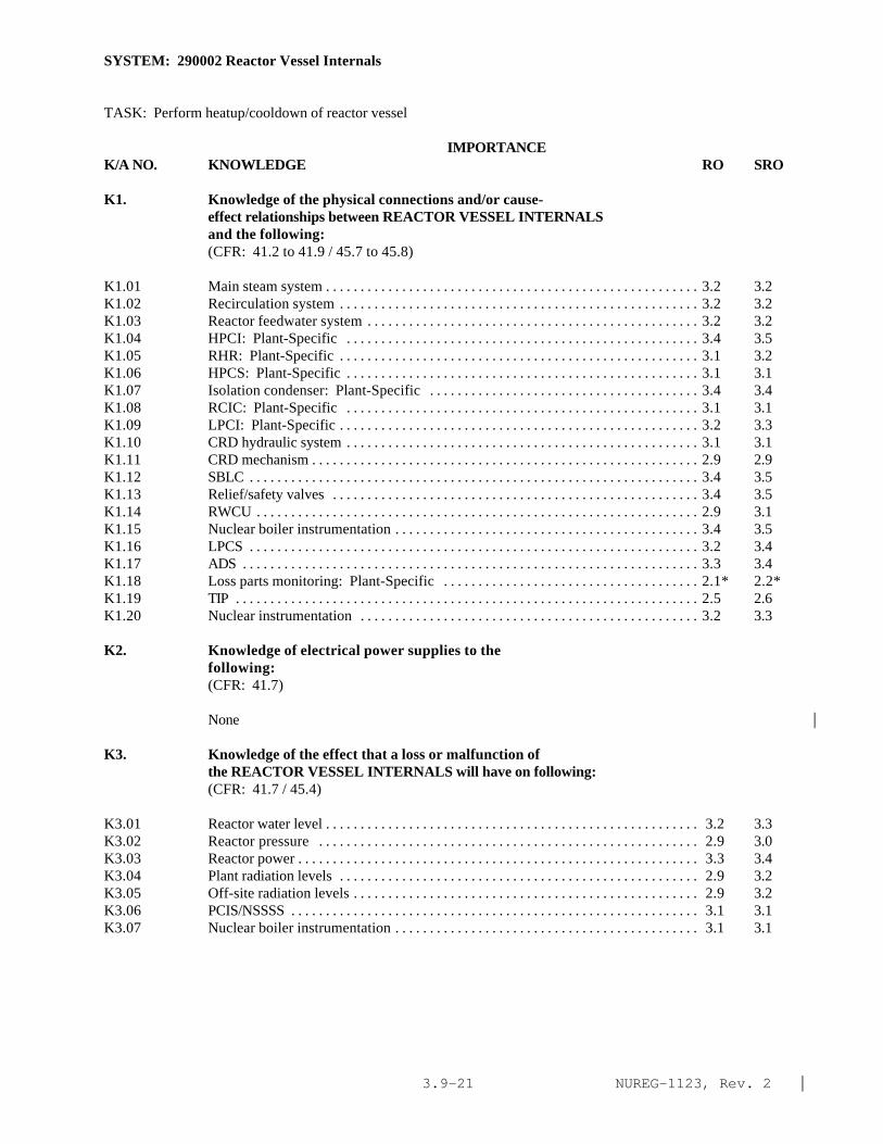
NUREG-1123, Rev. 2 |3.9-21
SYSTEM: 290002 Reactor Vessel Internals
TASK: Perform heatup/cooldown of reactor vessel
IMPORTANCE K/A NO. KNOWLEDGE RO SRO
K1. Knowledge of the physical connections and/or cause-effect relationships between REACTOR VESSEL INTERNALSand the following:(CFR: 41.2 to 41.9 / 45.7 to 45.8)
K1.01 Main steam system . . . . . . . . . . . . . . . . . . . . . . . . . . . . . . . . . . . . . . . . . . . . . . . . . . . . . . 3.2 3.2K1.02 Recirculation system . . . . . . . . . . . . . . . . . . . . . . . . . . . . . . . . . . . . . . . . . . . . . . . . . . . . 3.2 3.2K1.03 Reactor feedwater system . . . . . . . . . . . . . . . . . . . . . . . . . . . . . . . . . . . . . . . . . . . . . . . . 3.2 3.2K1.04 HPCI: Plant-Specific . . . . . . . . . . . . . . . . . . . . . . . . . . . . . . . . . . . . . . . . . . . . . . . . . . . 3.4 3.5K1.05 RHR: Plant-Specific . . . . . . . . . . . . . . . . . . . . . . . . . . . . . . . . . . . . . . . . . . . . . . . . . . . . 3.1 3.2K1.06 HPCS: Plant-Specific . . . . . . . . . . . . . . . . . . . . . . . . . . . . . . . . . . . . . . . . . . . . . . . . . . . 3.1 3.1K1.07 Isolation condenser: Plant-Specific . . . . . . . . . . . . . . . . . . . . . . . . . . . . . . . . . . . . . . . 3.4 3.4K1.08 RCIC: Plant-Specific . . . . . . . . . . . . . . . . . . . . . . . . . . . . . . . . . . . . . . . . . . . . . . . . . . . 3.1 3.1K1.09 LPCI: Plant-Specific . . . . . . . . . . . . . . . . . . . . . . . . . . . . . . . . . . . . . . . . . . . . . . . . . . . . 3.2 3.3K1.10 CRD hydraulic system . . . . . . . . . . . . . . . . . . . . . . . . . . . . . . . . . . . . . . . . . . . . . . . . . . . 3.1 3.1K1.11 CRD mechanism . . . . . . . . . . . . . . . . . . . . . . . . . . . . . . . . . . . . . . . . . . . . . . . . . . . . . . . . 2.9 2.9K1.12 SBLC . . . . . . . . . . . . . . . . . . . . . . . . . . . . . . . . . . . . . . . . . . . . . . . . . . . . . . . . . . . . . . . . . 3.4 3.5K1.13 Relief/safety valves . . . . . . . . . . . . . . . . . . . . . . . . . . . . . . . . . . . . . . . . . . . . . . . . . . . . . 3.4 3.5K1.14 RWCU . . . . . . . . . . . . . . . . . . . . . . . . . . . . . . . . . . . . . . . . . . . . . . . . . . . . . . . . . . . . . . . . 2.9 3.1K1.15 Nuclear boiler instrumentation . . . . . . . . . . . . . . . . . . . . . . . . . . . . . . . . . . . . . . . . . . . . 3.4 3.5K1.16 LPCS . . . . . . . . . . . . . . . . . . . . . . . . . . . . . . . . . . . . . . . . . . . . . . . . . . . . . . . . . . . . . . . . . 3.2 3.4K1.17 ADS . . . . . . . . . . . . . . . . . . . . . . . . . . . . . . . . . . . . . . . . . . . . . . . . . . . . . . . . . . . . . . . . . . 3.3 3.4K1.18 Loss parts monitoring: Plant-Specific . . . . . . . . . . . . . . . . . . . . . . . . . . . . . . . . . . . . . 2.1* 2.2*K1.19 TIP . . . . . . . . . . . . . . . . . . . . . . . . . . . . . . . . . . . . . . . . . . . . . . . . . . . . . . . . . . . . . . . . . . . 2.5 2.6K1.20 Nuclear instrumentation . . . . . . . . . . . . . . . . . . . . . . . . . . . . . . . . . . . . . . . . . . . . . . . . . 3.2 3.3
K2. Knowledge of electrical power supplies to thefollowing:(CFR: 41.7)
None |
K3. Knowledge of the effect that a loss or malfunction ofthe REACTOR VESSEL INTERNALS will have on following:(CFR: 41.7 / 45.4)
K3.01 Reactor water level . . . . . . . . . . . . . . . . . . . . . . . . . . . . . . . . . . . . . . . . . . . . . . . . . . . . . . 3.2 3.3K3.02 Reactor pressure . . . . . . . . . . . . . . . . . . . . . . . . . . . . . . . . . . . . . . . . . . . . . . . . . . . . . . . 2.9 3.0K3.03 Reactor power . . . . . . . . . . . . . . . . . . . . . . . . . . . . . . . . . . . . . . . . . . . . . . . . . . . . . . . . . . 3.3 3.4K3.04 Plant radiation levels . . . . . . . . . . . . . . . . . . . . . . . . . . . . . . . . . . . . . . . . . . . . . . . . . . . . 2.9 3.2K3.05 Off-site radiation levels . . . . . . . . . . . . . . . . . . . . . . . . . . . . . . . . . . . . . . . . . . . . . . . . . . 2.9 3.2K3.06 PCIS/NSSSS . . . . . . . . . . . . . . . . . . . . . . . . . . . . . . . . . . . . . . . . . . . . . . . . . . . . . . . . . . . 3.1 3.1K3.07 Nuclear boiler instrumentation . . . . . . . . . . . . . . . . . . . . . . . . . . . . . . . . . . . . . . . . . . . . 3.1 3.1

NUREG-1123, Rev. 2 |3.9-22
SYSTEM: 290002 Reactor Vessel Internals
Tasks as noted previously
IMPORTANCE K/A NO. KNOWLEDGE RO SRO
K4. Knowledge of REACTOR VESSEL INTERNALS designfeature(s) and/or interlocks which provide for thefollowing:(CFR: 41.7)
K4.01 2/3 core coverage following a DBA LOCA . . . . . . . . . . . . . . . . . . . . . . . . . . . . . . . . . . . 3.7 3.9K4.02 Separation of fluid flow paths within the vessel . . . . . . . . . . . . . . . . . . . . . . . . . . . . . . . 3.1 3.2K4.03 Core orificing . . . . . . . . . . . . . . . . . . . . . . . . . . . . . . . . . . . . . . . . . . . . . . . . . . . . . . . . . . . 3.2 3.3K4.04 Moisture removal from generated steam . . . . . . . . . . . . . . . . . . . . . . . . . . . . . . . . . . . . . 2.8 2.8K4.05 Natural circulation . . . . . . . . . . . . . . . . . . . . . . . . . . . . . . . . . . . . . . . . . . . . . . . . . . . . . . . 3.3 3.5
K5. Knowledge of the operational implications of thefollowing concepts as they apply to REACTOR VESSELINTERNALS :(CFR: 41.5 / 45.3)
K5.01 †Thermal limits . . . . . . . . . . . . . . . . . . . . . . . . . . . . . . . . . . . . . . . . . . . . . . . . . . . . . . . . 3.5 3.9K5.02 Fission product poisons . . . . . . . . . . . . . . . . . . . . . . . . . . . . . . . . . . . . . . . . . . . . . . . . . . 2.9 3.1K5.03 Burnable poisons . . . . . . . . . . . . . . . . . . . . . . . . . . . . . . . . . . . . . . . . . . . . . . . . . . . . . . . 2.7 3.0K5.04 †PCIOMR Plant-Specific . . . . . . . . . . . . . . . . . . . . . . . . . . . . . . . . . . . . . . . . . . . . . . . . 3.1 3.7K5.05 Brittle fracture . . . . . . . . . . . . . . . . . . . . . . . . . . . . . . . . . . . . . . . . . . . . . . . . . . . . . . . . . 3.1 3.3K5.06 Heat transfer mechanisms . . . . . . . . . . . . . . . . . . . . . . . . . . . . . . . . . . . . . . . . . . . . . . . . 2.8 3.2K5.07 †Safety limits . . . . . . . . . . . . . . . . . . . . . . . . . . . . . . . . . . . . . . . . . . . . . . . . . . . . . . . . . . 3.9 4.4*
K6. Knowledge of the effect that a loss or malfunction ofthe following will have on the REACTOR VESSELINTERNALS :(CFR: 41.7 / 45.7)
K6.01 CRD hydraulic system . . . . . . . . . . . . . . . . . . . . . . . . . . . . . . . . . . . . . . . . . . . . . . . . . . . 2.8 2.9K6.02 CRD mechanism . . . . . . . . . . . . . . . . . . . . . . . . . . . . . . . . . . . . . . . . . . . . . . . . . . . . . . . . 2.9 2.9K6.03 Recirculation system . . . . . . . . . . . . . . . . . . . . . . . . . . . . . . . . . . . . . . . . . . . . . . . . . . . . 3.1 3.2K6.04 Reactor feedwater system . . . . . . . . . . . . . . . . . . . . . . . . . . . . . . . . . . . . . . . . . . . . . . . . 3.0 3.1K6.05 SBLC . . . . . . . . . . . . . . . . . . . . . . . . . . . . . . . . . . . . . . . . . . . . . . . . . . . . . . . . . . . . . . . . . 3.3 3.4K6.06 Relief/safety valves . . . . . . . . . . . . . . . . . . . . . . . . . . . . . . . . . . . . . . . . . . . . . . . . . . . . . 3.0 3.2K6.07 RWCU . . . . . . . . . . . . . . . . . . . . . . . . . . . . . . . . . . . . . . . . . . . . . . . . . . . . . . . . . . . . . . . . 2.6 2.7K6.08 Nuclear boiler instrumentation . . . . . . . . . . . . . . . . . . . . . . . . . . . . . . . . . . . . . . . . . . . . 2.9 3.2K6.09 LPCS . . . . . . . . . . . . . . . . . . . . . . . . . . . . . . . . . . . . . . . . . . . . . . . . . . . . . . . . . . . . . . . . . 3.2 3.3K6.10 HPCI: Plant-Specific . . . . . . . . . . . . . . . . . . . . . . . . . . . . . . . . . . . . . . . . . . . . . . . . . . . 3.0 3.3K6.11 RHR: Plant-Specific . . . . . . . . . . . . . . . . . . . . . . . . . . . . . . . . . . . . . . . . . . . . . . . . . . . . 3.1 3.2K6.12 Isolation condenser: Plant-Specific . . . . . . . . . . . . . . . . . . . . . . . . . . . . . . . . . . . . . . . 3.0 3.2K6.13 RCIC: Plant-Specific . . . . . . . . . . . . . . . . . . . . . . . . . . . . . . . . . . . . . . . . . . . . . . . . . . . 2.7 2.8K6.14 LPCI: Plant-Specific . . . . . . . . . . . . . . . . . . . . . . . . . . . . . . . . . . . . . . . . . . . . . . . . . . . . 3.1 3.3K6.15 ADS . . . . . . . . . . . . . . . . . . . . . . . . . . . . . . . . . . . . . . . . . . . . . . . . . . . . . . . . . . . . . . . . . . 3.1 3.4K6.16 Loss parts monitoring . . . . . . . . . . . . . . . . . . . . . . . . . . . . . . . . . . . . . . . . . . . . . . . . . . . 2.0* 2.0*K6.17 TIP . . . . . . . . . . . . . . . . . . . . . . . . . . . . . . . . . . . . . . . . . . . . . . . . . . . . . . . . . . . . . . . . . . . 2.5 2.5

NUREG-1123, Rev. 2 |3.9-23
SYSTEM: 290002 Reactor Vessel Internals
Tasks as noted previously
IMPORTANCE K/A NO. KNOWLEDGE RO SRO
K6.18 Nuclear instrumentation . . . . . . . . . . . . . . . . . . . . . . . . . . . . . . . . . . . . . . . . . . . . . . . . . 3.0 3.1K6.19 HPCS: Plant-Specific(BWR-5&6) . . . . . . . . . . . . . . . . . . . . . . . . . . . . . . . . . . . . . . . . 3.0 3.1K6.20 Main steam system . . . . . . . . . . . . . . . . . . . . . . . . . . . . . . . . . . . . . . . . . . . . . . . . . . . . . . 2.9 3.1
ABILITY
A1. Ability to predict and/or monitor changes inparameters associated with operating the REACTORVESSEL INTERNALS controls including:(CFR: 41.5 / 45.5)
None |
A2. Ability to (a) predict the impacts of the following onthe REACTOR VESSEL INTERNALS ; and (b) based on thosepredictions, use procedures to correct, control, ormitigate the consequences of those abnormal conditionsor operations:(CFR: 41.5 / 45.6)
A2.01 LOCA . . . . . . . . . . . . . . . . . . . . . . . . . . . . . . . . . . . . . . . . . . . . . . . . . . . . . . . . . . . . . . . . . 3.7 4.0A2.02 †Overpressurization transient . . . . . . . . . . . . . . . . . . . . . . . . . . . . . . . . . . . . . . . . . . . . . 3.6 3.9A2.03 †Control rod drop accident . . . . . . . . . . . . . . . . . . . . . . . . . . . . . . . . . . . . . . . . . . . . . . . 3.6 3.9A2.04 Excessive heatup/cooldown rate . . . . . . . . . . . . . . . . . . . . . . . . . . . . . . . . . . . . . . . . . . . 3.7 4.1A2.05 †Exceeding thermal limits . . . . . . . . . . . . . . . . . . . . . . . . . . . . . . . . . . . . . . . . . . . . . . . . 3.7 4.2A2.06 †Exceeding safety limits . . . . . . . . . . . . . . . . . . . . . . . . . . . . . . . . . . . . . . . . . . . . . . . . . 4.0 4.5*
A3. Ability to monitor automatic operations of the REACTORVESSEL INTERNALS including:(CFR: 41.7 / 45.7)
None ||
A4. Ability to manually operate and/or monitor in thecontrol room:(CFR: 41.7 / 45.5 to 45.8)
None |

NUREG-1123, Rev. 2 |3.9-24
SYSTEM: 233000 Fuel Pool Cooling and Clean-up
TASK: Lineup residual heat removal supplemental fuel pool cooling Monitor residual heat removal supplemental fuel pool cooling Startup the torus/suppression pool cleanup system (write in) Stop residual heat removal supplemental fuel pool cooling Shutdown the torus/suppression pool cleanup system (write in) Monitor RHR supplemental fuel pool cooling (write in) Perform lineups on spent fuel pool cooling system Fill the spent fuel pools Startup the spent fuel pool cooling system in different pump/heat exchanger combinations Perform spent fuel pool purification using filter Perform spent fuel pool purification using demineralizer Backwash spent fuel pool filter Change spent fuel pool filter Replace resin in spent fuel pool demineralizer Operate system between refueling pool and spent fuel pool in different lineups Operate the spent fuel pool skimmer loop Monitor spent fuel pool cooling system operation Perform borated water storage tank purification using filter Perform borated water storage tank purification using demineralizerRecirculate the spent fuel pool Lower refueling pool level Fill and vent the spent fuel pool purification system Perform spent fuel pool leakage test Fill the fuel transfer canal Drain the fuel transfer canal Perform fuel transfer canal purification Recirculate fuel transfer canal Perform decay heat removal using the spent fuel cooling system Shutdown the spent fuel pool cooling system Fill the dryer-separator pit Drain the dryer-separator pit Conduct nitrogen mixing of spent fuel pool cooling demineralizer resin
IMPORTANCE K/A NO. KNOWLEDGE RO SRO
K1. Knowledge of the physical connections and/or cause-effect relationships between FUEL POOL COOLING ANDCLEAN-UP and the following:(CFR: 41.2 to 41.9 / 45.7 to 45.8)
K1.01 Shutdown cooling system: Plant-Specific . . . . . . . . . . . . . . . . . . . . . . . . . . . . . . . . . . 2.6 2.9K1.02 Residual heat removal system: Plant-Specific . . . . . . . . . . . . . . . . . . . . . . . . . . . . . . . 2.9 3.0K1.03 Condensate storage tank . . . . . . . . . . . . . . . . . . . . . . . . . . . . . . . . . . . . . . . . . . . . . . . . . 2.3 2.3K1.04 Process sampling system . . . . . . . . . . . . . . . . . . . . . . . . . . . . . . . . . . . . . . . . . . . . . . . . . 2.0* 2.0*
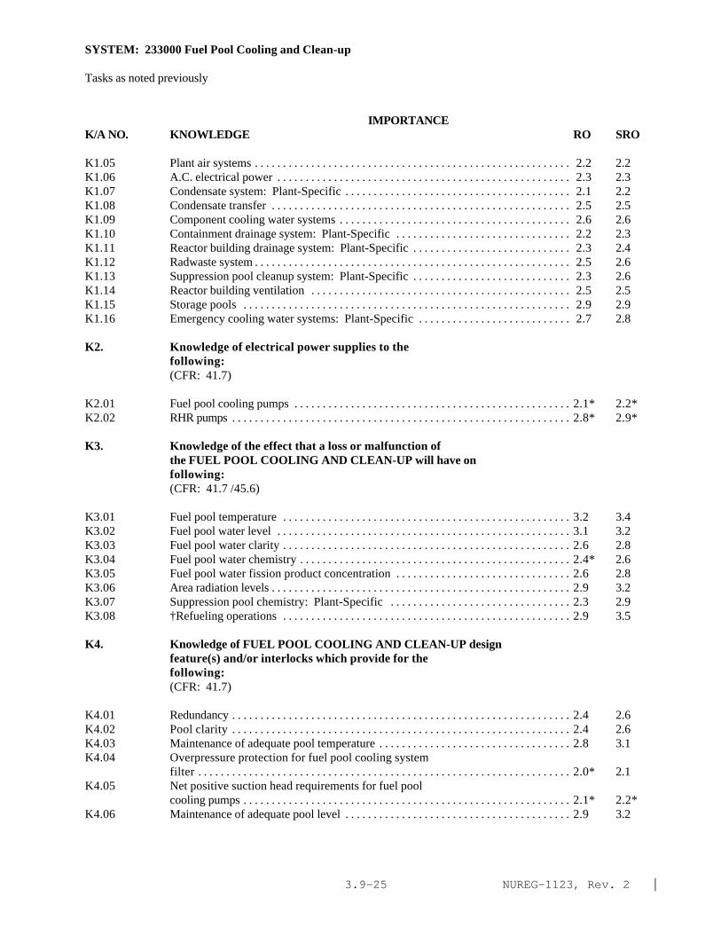
NUREG-1123, Rev. 2 |3.9-25
SYSTEM: 233000 Fuel Pool Cooling and Clean-up
Tasks as noted previously
IMPORTANCE K/A NO. KNOWLEDGE RO SRO
K1.05 Plant air systems . . . . . . . . . . . . . . . . . . . . . . . . . . . . . . . . . . . . . . . . . . . . . . . . . . . . . . . . 2.2 2.2K1.06 A.C. electrical power . . . . . . . . . . . . . . . . . . . . . . . . . . . . . . . . . . . . . . . . . . . . . . . . . . . . 2.3 2.3K1.07 Condensate system: Plant-Specific . . . . . . . . . . . . . . . . . . . . . . . . . . . . . . . . . . . . . . . . 2.1 2.2K1.08 Condensate transfer . . . . . . . . . . . . . . . . . . . . . . . . . . . . . . . . . . . . . . . . . . . . . . . . . . . . . 2.5 2.5K1.09 Component cooling water systems . . . . . . . . . . . . . . . . . . . . . . . . . . . . . . . . . . . . . . . . . 2.6 2.6K1.10 Containment drainage system: Plant-Specific . . . . . . . . . . . . . . . . . . . . . . . . . . . . . . . 2.2 2.3K1.11 Reactor building drainage system: Plant-Specific . . . . . . . . . . . . . . . . . . . . . . . . . . . . 2.3 2.4K1.12 Radwaste system . . . . . . . . . . . . . . . . . . . . . . . . . . . . . . . . . . . . . . . . . . . . . . . . . . . . . . . . 2.5 2.6K1.13 Suppression pool cleanup system: Plant-Specific . . . . . . . . . . . . . . . . . . . . . . . . . . . . 2.3 2.6K1.14 Reactor building ventilation . . . . . . . . . . . . . . . . . . . . . . . . . . . . . . . . . . . . . . . . . . . . . . 2.5 2.5K1.15 Storage pools . . . . . . . . . . . . . . . . . . . . . . . . . . . . . . . . . . . . . . . . . . . . . . . . . . . . . . . . . . 2.9 2.9K1.16 Emergency cooling water systems: Plant-Specific . . . . . . . . . . . . . . . . . . . . . . . . . . . 2.7 2.8
K2. Knowledge of electrical power supplies to thefollowing:(CFR: 41.7)
K2.01 Fuel pool cooling pumps . . . . . . . . . . . . . . . . . . . . . . . . . . . . . . . . . . . . . . . . . . . . . . . . . 2.1* 2.2*K2.02 RHR pumps . . . . . . . . . . . . . . . . . . . . . . . . . . . . . . . . . . . . . . . . . . . . . . . . . . . . . . . . . . . . 2.8* 2.9*
K3. Knowledge of the effect that a loss or malfunction ofthe FUEL POOL COOLING AND CLEAN-UP will have onfollowing:(CFR: 41.7 /45.6)
K3.01 Fuel pool temperature . . . . . . . . . . . . . . . . . . . . . . . . . . . . . . . . . . . . . . . . . . . . . . . . . . . 3.2 3.4K3.02 Fuel pool water level . . . . . . . . . . . . . . . . . . . . . . . . . . . . . . . . . . . . . . . . . . . . . . . . . . . . 3.1 3.2K3.03 Fuel pool water clarity . . . . . . . . . . . . . . . . . . . . . . . . . . . . . . . . . . . . . . . . . . . . . . . . . . . 2.6 2.8K3.04 Fuel pool water chemistry . . . . . . . . . . . . . . . . . . . . . . . . . . . . . . . . . . . . . . . . . . . . . . . . 2.4* 2.6K3.05 Fuel pool water fission product concentration . . . . . . . . . . . . . . . . . . . . . . . . . . . . . . . 2.6 2.8K3.06 Area radiation levels . . . . . . . . . . . . . . . . . . . . . . . . . . . . . . . . . . . . . . . . . . . . . . . . . . . . . 2.9 3.2K3.07 Suppression pool chemistry: Plant-Specific . . . . . . . . . . . . . . . . . . . . . . . . . . . . . . . . 2.3 2.9K3.08 †Refueling operations . . . . . . . . . . . . . . . . . . . . . . . . . . . . . . . . . . . . . . . . . . . . . . . . . . . 2.9 3.5
K4. Knowledge of FUEL POOL COOLING AND CLEAN-UP designfeature(s) and/or interlocks which provide for thefollowing:(CFR: 41.7)
K4.01 Redundancy . . . . . . . . . . . . . . . . . . . . . . . . . . . . . . . . . . . . . . . . . . . . . . . . . . . . . . . . . . . . 2.4 2.6K4.02 Pool clarity . . . . . . . . . . . . . . . . . . . . . . . . . . . . . . . . . . . . . . . . . . . . . . . . . . . . . . . . . . . . 2.4 2.6K4.03 Maintenance of adequate pool temperature . . . . . . . . . . . . . . . . . . . . . . . . . . . . . . . . . . 2.8 3.1K4.04 Overpressure protection for fuel pool cooling system
filter . . . . . . . . . . . . . . . . . . . . . . . . . . . . . . . . . . . . . . . . . . . . . . . . . . . . . . . . . . . . . . . . . . 2.0* 2.1K4.05 Net positive suction head requirements for fuel pool
cooling pumps . . . . . . . . . . . . . . . . . . . . . . . . . . . . . . . . . . . . . . . . . . . . . . . . . . . . . . . . . . 2.1* 2.2*K4.06 Maintenance of adequate pool level . . . . . . . . . . . . . . . . . . . . . . . . . . . . . . . . . . . . . . . . 2.9 3.2

NUREG-1123, Rev. 2 |3.9-26
SYSTEM: 233000 Fuel Pool Cooling and Clean-up
Tasks as noted previously
IMPORTANCE K/A NO. KNOWLEDGE RO SRO
K4.07 Supplemental heat removal capability . . . . . . . . . . . . . . . . . . . . . . . . . . . . . . . . . . . . . . 2.7 2.9K4.08 Pool cooling during loss of coolant accident: BWR-6 . . . . . . . . . . . . . . . . . . . . . . . . 2.6* 2.8K4.09 Maintenance of filter/demineralizer precoat during low
flow conditions . . . . . . . . . . . . . . . . . . . . . . . . . . . . . . . . . . . . . . . . . . . . . . . . . . . . . . . . . 2.1* 2.4*
K5. Knowledge of the operational implications of thefollowing concepts as they apply to FUEL POOL COOLINGAND CLEAN-UP :(CFR: 41.5 / 45.3)
K5.01 Heat removal mechanisms . . . . . . . . . . . . . . . . . . . . . . . . . . . . . . . . . . . . . . . . . . . . . . . . 2.5 2.7K5.02 Pump cavitation . . . . . . . . . . . . . . . . . . . . . . . . . . . . . . . . . . . . . . . . . . . . . . . . . . . . . . . . 2.1* 2.2*K5.03 Spent fuel decay heat generation . . . . . . . . . . . . . . . . . . . . . . . . . . . . . . . . . . . . . . . . . . . 2.6 2.8K5.04 Demineralizer ion exchange . . . . . . . . . . . . . . . . . . . . . . . . . . . . . . . . . . . . . . . . . . . . . . 2.0* 2.2*K5.05 Mechanical filtration operation . . . . . . . . . . . . . . . . . . . . . . . . . . . . . . . . . . . . . . . . . . . 2.1* 2.2*K5.06 Maximum normal heat load . . . . . . . . . . . . . . . . . . . . . . . . . . . . . . . . . . . . . . . . . . . . . . . 2.5 2.7K5.07 Maximum (abnormal) heat 102d . . . . . . . . . . . . . . . . . . . . . . . . . . . . . . . . . . . . . . . . . . . 2.5 2.8
K6. Knowledge of the effect that a loss or malfunction ofthe following will have on the FUEL POOL COOLING ANDCLEAN-UP :(CFR: 41.7 / 45.7)
K6.01 A.C. electrical power . . . . . . . . . . . . . . . . . . . . . . . . . . . . . . . . . . . . . . . . . . . . . . . . . . . . 2.5 2.7K6.02 Shutdown cooling system: Plant-Specific . . . . . . . . . . . . . . . . . . . . . . . . . . . . . . . . . . 2.2* 2.5*K6.03 Residual heat removal: Plant-Specific . . . . . . . . . . . . . . . . . . . . . . . . . . . . . . . . . . . . . 2.3 2.7K6.04 Condensate transfer . . . . . . . . . . . . . . . . . . . . . . . . . . . . . . . . . . . . . . . . . . . . . . . . . . . . . 2.5 2.6K6.05 Condensate system . . . . . . . . . . . . . . . . . . . . . . . . . . . . . . . . . . . . . . . . . . . . . . . . . . . . . . 2.1* 2.3K6.06 Condensate storage tanks . . . . . . . . . . . . . . . . . . . . . . . . . . . . . . . . . . . . . . . . . . . . . . . . . 2.4 2.4K6.07 Component cooling water systems . . . . . . . . . . . . . . . . . . . . . . . . . . . . . . . . . . . . . . . . . 2.7 2.8K6.08 Plant air systems . . . . . . . . . . . . . . . . . . . . . . . . . . . . . . . . . . . . . . . . . . . . . . . . . . . . . . . 2.4 2.4K6.09 Radwaste system . . . . . . . . . . . . . . . . . . . . . . . . . . . . . . . . . . . . . . . . . . . . . . . . . . . . . . . . 2.2 2.4K6.10 Reactor cavity seal failure . . . . . . . . . . . . . . . . . . . . . . . . . . . . . . . . . . . . . . . . . . . . . . . . 2.9 3.3K6.11 NSSSS/PCIS: Plant-Specific . . . . . . . . . . . . . . . . . . . . . . . . . . . . . . . . . . . . . . . . . . . . . 2.3 2.6*
ABILITY
Al. Ability to predict and/or monitor changes inparameters associated with operating the FUEL POOLCOOLING AND CLEAN-UP controls including:(CFR: 41.5 / 45.5)
A1.01 Surge tank level . . . . . . . . . . . . . . . . . . . . . . . . . . . . . . . . . . . . . . . . . . . . . . . . . . . . . . . . 2.6 2.9Al.02 Pool level . . . . . . . . . . . . . . . . . . . . . . . . . . . . . . . . . . . . . . . . . . . . . . . . . . . . . . . . . . . . . 2.9 3.1Al.03 Pool temperature . . . . . . . . . . . . . . . . . . . . . . . . . . . . . . . . . . . . . . . . . . . . . . . . . . . . . . . 3.1 3.3Al.04 Pump discharge pressure . . . . . . . . . . . . . . . . . . . . . . . . . . . . . . . . . . . . . . . . . . . . . . . . . 2.4 2.5Al.05 Filter/ demineralize differential pressure . . . . . . . . . . . . . . . . . . . . . . . . . . . . . . . . . . . 2.4* 2.3*|

NUREG-1123, Rev. 2 |3.9-27
SYSTEM: 233000 Fuel Pool Cooling and Clean-up
Tasks as noted previously
IMPORTANCE K/A NO. ABILITY RO SRO
Al.06 System flow . . . . . . . . . . . . . . . . . . . . . . . . . . . . . . . . . . . . . . . . . . . . . . . . . . . . . . . . . . . 2.5 2.4Al.07 System temperature . . . . . . . . . . . . . . . . . . . . . . . . . . . . . . . . . . . . . . . . . . . . . . . . . . . . . 2.7 2.8Al.08 Pool chemistry . . . . . . . . . . . . . . . . . . . . . . . . . . . . . . . . . . . . . . . . . . . . . . . . . . . . . . . . . 2.1* 2.4* |Al.09 Pool clarity . . . . . . . . . . . . . . . . . . . . . . . . . . . . . . . . . . . . . . . . . . . . . . . . . . . . . . . . . . . . 2.4 2.6A1.10 Pool activity levels . . . . . . . . . . . . . . . . . . . . . . . . . . . . . . . . . . . . . . . . . . . . . . . . . . . . . . 2.4 2.6*A1.11 Suppression pool chemistry: BWR-6 . . . . . . . . . . . . . . . . . . . . . . . . . . . . . . . . . . . . . . 2.4 2.9
A2. Ability to (a) predict the impacts of the following onthe FUEL POOL COOLING AND CLEAN-UP ; and (b) based onthose predictions, use procedures to correct, control,or mitigate the consequences of those abnormalconditions or operations:(CFR: 41.5 / 45.6)
A2.01 High pool level . . . . . . . . . . . . . . . . . . . . . . . . . . . . . . . . . . . . . . . . . . . . . . . . . . . . . . . . . 2.7 2.9A2.02 Low pool level . . . . . . . . . . . . . . . . . . . . . . . . . . . . . . . . . . . . . . . . . . . . . . . . . . . . . . . . . 3.1 3.3A2.03 Low surge tank level/high level . . . . . . . . . . . . . . . . . . . . . . . . . . . . . . . . . . . . . . . . . . . . 2.8 3.0A2.04 Pump trip . . . . . . . . . . . . . . . . . . . . . . . . . . . . . . . . . . . . . . . . . . . . . . . . . . . . . . . . . . . . . . 2.6 2.7A2.05 Valve closures . . . . . . . . . . . . . . . . . . . . . . . . . . . . . . . . . . . . . . . . . . . . . . . . . . . . . . . . . . 2.5 2.5A2.06 Valve openings . . . . . . . . . . . . . . . . . . . . . . . . . . . . . . . . . . . . . . . . . . . . . . . . . . . . . . . . . 2.5 2.5A2.07 High fuel pool temperature . . . . . . . . . . . . . . . . . . . . . . . . . . . . . . . . . . . . . . . . . . . . . . . 3.0 3.2A2.08 Closed cooling water failure . . . . . . . . . . . . . . . . . . . . . . . . . . . . . . . . . . . . . . . . . . . . . . 2.9 3.1A2.09 A.C. electrical power failures . . . . . . . . . . . . . . . . . . . . . . . . . . . . . . . . . . . . . . . . . . . . . 2.7 2.9A2.10 Refueling bellows seal high flow . . . . . . . . . . . . . . . . . . . . . . . . . . . . . . . . . . . . . . . . . . 2.9 3.3A2.11 Fuel pool gate seal high flow. . . . . . . . . . . . . . . . . . . . . . . . . . . . . . . . . . . . . . . . . . . . . . 2.9 3.2A2.12 High filter/ demineralizer differential pressure . . . . . . . . . . . . . . . . . . . . . . . . . . . . . . 2.4* 2.4A2.13 Low filter/ demineralizer differential pressure . . . . . . . . . . . . . . . . . . . . . . . . . . . . . . . 2.2* 2.2* |A2.14 Low system flow . . . . . . . . . . . . . . . . . . . . . . . . . . . . . . . . . . . . . . . . . . . . . . . . . . . . . . . 2.3 2.3A2.15 High system temperature . . . . . . . . . . . . . . . . . . . . . . . . . . . . . . . . . . . . . . . . . . . . . . . . . 2.8 2.9A2.16 Loss of coolant accident signal . . . . . . . . . . . . . . . . . . . . . . . . . . . . . . . . . . . . . . . . . . . 2.5 2.8A2.17 Fuel transfer tube drain tank high level/low level:
BWR-6 . . . . . . . . . . . . . . . . . . . . . . . . . . . . . . . . . . . . . . . . . . . . . . . . . . . . . . . . . . . . . . . 2.8 2.8 |A2.18 Low pool clarity . . . . . . . . . . . . . . . . . . . . . . . . . . . . . . . . . . . . . . . . . . . . . . . . . . . . . . . . 2.5 2.7A2.19 Inadequate system/pool chemistry . . . . . . . . . . . . . . . . . . . . . . . . . . . . . . . . . . . . . . . . . 2.5 2.8
A3. Ability to monitor automatic operations of the FUELPOOL COOLING AND CLEAN-UP including:(CFR: 41.7 / 45.7)
A3.01 Valve operation . . . . . . . . . . . . . . . . . . . . . . . . . . . . . . . . . . . . . . . . . . . . . . . . . . . . . . . . . 2.4 2.5A3.02 Pump trip(s) . . . . . . . . . . . . . . . . . . . . . . . . . . . . . . . . . . . . . . . . . . . . . . . . . . . . . . . . . . . 2.6 2.6A3.03 System indicating lights and alarms . . . . . . . . . . . . . . . . . . . . . . . . . . . . . . . . . . . . . . . . 2.6 2.6

NUREG-1123, Rev. 2 |3.9-28
SYSTEM: 233000 Fuel Pool Cooling and Clean-up
Tasks as noted previously
IMPORTANCE K/A NO. ABILITY RO SRO
A4. Ability to manually operate and/or monitor in thecontrol room:(CFR: 41.7 / 45.5 to 45.8)
A4.01 System lights and alarms . . . . . . . . . . . . . . . . . . . . . . . . . . . . . . . . . . . . . . . . . . . . . . . . . 2.6 2.6A4.02 System lineups . . . . . . . . . . . . . . . . . . . . . . . . . . . . . . . . . . . . . . . . . . . . . . . . . . . . . . . . . 2.3 2.5A4.03 System flow . . . . . . . . . . . . . . . . . . . . . . . . . . . . . . . . . . . . . . . . . . . . . . . . . . . . . . . . . . . 2.2 2.4A4.04 Pool level . . . . . . . . . . . . . . . . . . . . . . . . . . . . . . . . . . . . . . . . . . . . . . . . . . . . . . . . . . . . . 2.9* 3.1A4.05 Pool temperature . . . . . . . . . . . . . . . . . . . . . . . . . . . . . . . . . . . . . . . . . . . . . . . . . . . . . . . 2.7* 3.1*A4.06 System temperature . . . . . . . . . . . . . . . . . . . . . . . . . . . . . . . . . . . . . . . . . . . . . . . . . . . . . 2.5* 2.6* A4.07 System pressures . . . . . . . . . . . . . . . . . . . . . . . . . . . . . . . . . . . . . . . . . . . . . . . . . . . . . . . 2.2* 2.3*A4.08 System differential pressures . . . . . . . . . . . . . . . . . . . . . . . . . . . . . . . . . . . . . . . . . . . . . 2.2* 2.2*A4.09 Pump operation . . . . . . . . . . . . . . . . . . . . . . . . . . . . . . . . . . . . . . . . . . . . . . . . . . . . . . . . . 2.2* 2.2*A4.10 Tank levels . . . . . . . . . . . . . . . . . . . . . . . . . . . . . . . . . . . . . . . . . . . . . . . . . . . . . . . . . . . . . 2.5 2.6A4.11 Closed cooling water temperature . . . . . . . . . . . . . . . . . . . . . . . . . . . . . . . . . . . . . . . . . 2.5 2.5

NUREG-1123, Rev. 2 |3.9-29
SYSTEM: 261000 Standby Gas Treatment System
TASK: Perform lineups on the standby gas treatment systemPlace the standby gas treatment system in standby readinessPlace the standby gas treatment system in service manuallyMonitor the standby gas treatment system following automatic initiationRemove one standby gas treatment (SGTS) train from service after automatic initiationSecure the standby gas treatment system (SGTS)Perform standby gas treatment manual bypass valve operation, and simulated auto act testPerform standby gas treatment system logic system functional testPerform one circuit of standby gas treatment system inoperable test
IMPORTANCE K/A NO. KNOWLEDGE RO SRO
K1. Knowledge of the physical connections and/or cause-effect relationships between STANDBY GAS TREATMENTSYSTEM and the following:(CFR: 41.2 to 41.9 / 45.7 to 45.8)
K1.01 Reactor building ventilation system . . . . . . . . . . . . . . . . . . . . . . . . . . . . . . . . . . . . . . . . 3.4 3.6K1.02 Drywell . . . . . . . . . . . . . . . . . . . . . . . . . . . . . . . . . . . . . . . . . . . . . . . . . . . . . . . . . . . . . . . 3.2 3.4K1.03 Suppression pool . . . . . . . . . . . . . . . . . . . . . . . . . . . . . . . . . . . . . . . . . . . . . . . . . . . . . . . 2.9 3.1K1.04 High radiation sampling system . . . . . . . . . . . . . . . . . . . . . . . . . . . . . . . . . . . . . . . . . . . 2.5 2.8K1.05 Radwaste system: Plant-Specific . . . . . . . . . . . . . . . . . . . . . . . . . . . . . . . . . . . . . . . . . . 2.3 2.4K1.06 High pressure coolant injection system: Plant-
Specific . . . . . . . . . . . . . . . . . . . . . . . . . . . . . . . . . . . . . . . . . . . . . . . . . . . . . . . . . . . . . . . 3.0 3.1K1.07 Elevated release stack . . . . . . . . . . . . . . . . . . . . . . . . . . . . . . . . . . . . . . . . . . . . . . . . . . . 3.1 3.2K1.08 Process radiation monitoring system . . . . . . . . . . . . . . . . . . . . . . . . . . . . . . . . . . . . . . . 2.8 3.1K1.09 Primary containment isolation system . . . . . . . . . . . . . . . . . . . . . . . . . . . . . . . . . . . . . . 3.2 3.4K1.10 Plant air systems . . . . . . . . . . . . . . . . . . . . . . . . . . . . . . . . . . . . . . . . . . . . . . . . . . . . . . . . 2.2* 2.3K1.11 Primary containment pressure . . . . . . . . . . . . . . . . . . . . . . . . . . . . . . . . . . . . . . . . . . . . 3.2 3.3K1.12 Primary containment purge system: Plant-Specific . . . . . . . . . . . . . . . . . . . . . . . . . . . 3.1 3.2
K2. Knowledge of electrical power supplies to thefollowing:(CFR: 41.7)
K2.01 Fan power . . . . . . . . . . . . . . . . . . . . . . . . . . . . . . . . . . . . . . . . . . . . . . . . . . . . . . . . . . . . . 2.1* 2.3*K2.02 Valve power . . . . . . . . . . . . . . . . . . . . . . . . . . . . . . . . . . . . . . . . . . . . . . . . . . . . . . . . . . . . 1.9* 2.0*K2.03 Initiation logic . . . . . . . . . . . . . . . . . . . . . . . . . . . . . . . . . . . . . . . . . . . . . . . . . . . . . . . . . 2.3* 2.5*K2.04 Heater power . . . . . . . . . . . . . . . . . . . . . . . . . . . . . . . . . . . . . . . . . . . . . . . . . . . . . . . . . . . 1.7* 1.9*
K3. Knowledge of the effect that a loss or malfunction ofthe STANDBY GAS TREATMENT SYSTEM will have onfollowing:(CFR: 41.7 /45.6)
K3.01 Secondary containment and environment differentialpressure . . . . . . . . . . . . . . . . . . . . . . . . . . . . . . . . . . . . . . . . . . . . . . . . . . . . . . . . . . . . . . 3.3 3.6
K3.02 Off-site release rate . . . . . . . . . . . . . . . . . . . . . . . . . . . . . . . . . . . . . . . . . . . . . . . . . . . . . 3.6 3.9

NUREG-1123, Rev. 2 |3.9-30
SYSTEM: 261000 Standby Gas Treatment System
Tasks as noted previously
IMPORTANCE K/A NO. KNOWLEDGE RO SRO
K3.03 Primary containment pressure: Mark-I&II . . . . . . . . . . . . . . . . . . . . . . . . . . . . . . . . . . 3.2 3.4K3.04 High pressure coolant injection system: Plant-
Specific . . . . . . . . . . . . . . . . . . . . . . . . . . . . . . . . . . . . . . . . . . . . . . . . . . . . . . . . . . . . . . . 3.1 3.1K3.05 Secondary containment radiation/ contamination levels . . . . . . . . . . . . . . . . . . . . . . . 3.2 3.5|K3.06 Primary containment oxygen content: Mark-I&II . . . . . . . . . . . . . . . . . . . . . . . . . . . . 3.0 3.3|
K4. Knowledge of STANDBY GAS TREATMENT SYSTEM designfeature(s) and/or interlocks which provide for thefollowing:(CFR: 41.7)
K4.01 Automatic system initiation . . . . . . . . . . . . . . . . . . . . . . . . . . . . . . . . . . . . . . . . . . . . . . 3.7 3.8K4.02 Charcoal bed decay heat removal . . . . . . . . . . . . . . . . . . . . . . . . . . . . . . . . . . . . . . . . . . 2.6 2.8K4.03 Moisture removal . . . . . . . . . . . . . . . . . . . . . . . . . . . . . . . . . . . . . . . . . . . . . . . . . . . . . . . 2.5 2.7K4.04 Radioactive particulate filtration . . . . . . . . . . . . . . . . . . . . . . . . . . . . . . . . . . . . . . . . . . 2.7 2.9K4.05 Fission product gas removal . . . . . . . . . . . . . . . . . . . . . . . . . . . . . . . . . . . . . . . . . . . . . . 2.6 2.8K4.06 Charcoal bed retention . . . . . . . . . . . . . . . . . . . . . . . . . . . . . . . . . . . . . . . . . . . . . . . . . . . 2.4* 2.6
K5. Knowledge of the operational implications of thefollowing concepts as they apply to STANDBY GASTREATMENT SYSTEM :(CFR: 41.5 / 45.3)
K5.01 Heat removal mechanisms . . . . . . . . . . . . . . . . . . . . . . . . . . . . . . . . . . . . . . . . . . . . . . . . 2.3* 2.6*K5.02 Air operated valves: Plant-Specific . . . . . . . . . . . . . . . . . . . . . . . . . . . . . . . . . . . . . . . . 2.3* 2.5*
K6. Knowledge of the effect that a loss or malfunction ofthe following will have on the STANDBY GAS TREATMENTSYSTEM :(CFR: 41.7 / 45.7)
K6.01 A.C. electrical distribution . . . . . . . . . . . . . . . . . . . . . . . . . . . . . . . . . . . . . . . . . . . . . . . 2.9 3.0K6.02 D.C. electrical distribution . . . . . . . . . . . . . . . . . . . . . . . . . . . . . . . . . . . . . . . . . . . . . . . 2.4* 2.6*K6.03 Emergency diesel generator system . . . . . . . . . . . . . . . . . . . . . . . . . . . . . . . . . . . . . . . . 3.0 3.1K6.04 Process radiation monitoring . . . . . . . . . . . . . . . . . . . . . . . . . . . . . . . . . . . . . . . . . . . . . 2.9 3.1K6.05 Reactor protection system: Plant-Specific . . . . . . . . . . . . . . . . . . . . . . . . . . . . . . . . . . 3.1 3.2K6.06 Plant air systems . . . . . . . . . . . . . . . . . . . . . . . . . . . . . . . . . . . . . . . . . . . . . . . . . . . . . . . . 2.4 2.6K6.07 Primary containment atmosphere sampling system:
Plant-Specific . . . . . . . . . . . . . . . . . . . . . . . . . . . . . . . . . . . . . . . . . . . . . . . . . . . . . . . . . . 2.2* 2.4K6.08 Reactor vessel level: Plant-Specific . . . . . . . . . . . . . . . . . . . . . . . . . . . . . . . . . . . . . . . 3.1 3.1K6.09 Primary containment high pressure: Plant-Specific . . . . . . . . . . . . . . . . . . . . . . . . . . 3.1 3.3

NUREG-1123, Rev. 2 |3.9-31
SYSTEM: 261000 Standby Gas Treatment System
Tasks as noted previously
IMPORTANCE K/A NO. KNOWLEDGE RO SRO
ABILITY
A1. Ability to predict and/or monitor changes inparameters associated with operating the STANDBY GASTREATMENT SYSTEM controls including:(CFR: 41.5 / 45.5)
A1.01 System flow . . . . . . . . . . . . . . . . . . . . . . . . . . . . . . . . . . . . . . . . . . . . . . . . . . . . . . . . . . . 2.9 3.1A1.02 Primary containment pressure . . . . . . . . . . . . . . . . . . . . . . . . . . . . . . . . . . . . . . . . . . . . 3.1 3.2A1.03 †Off-site release levels . . . . . . . . . . . . . . . . . . . . . . . . . . . . . . . . . . . . . . . . . . . . . . . . . . 3.2 3.8A1.04 Secondary containment differential pressure . . . . . . . . . . . . . . . . . . . . . . . . . . . . . . . . 3.0 3.3A1.05 Primary containment oxygen level: Mark-I&II . . . . . . . . . . . . . . . . . . . . . . . . . . . . . . . 2.7* 2.9*A1.06 Drywell and suppression chamber differential pressure:
Mark-I . . . . . . . . . . . . . . . . . . . . . . . . . . . . . . . . . . . . . . . . . . . . . . . . . . . . . . . . . . . . . . . . 2.7 3.0A1.07 SBGTS train temperature . . . . . . . . . . . . . . . . . . . . . . . . . . . . . . . . . . . . . . . . . . . . . . . . . 2.8 2.9
A2. Ability to (a) predict the impacts of the following onthe STANDBY GAS TREATMENT SYSTEM ; and (b) based onthose predictions, use procedures to correct, control,or mitigate the consequences of those abnormalconditions or operations:(CFR: 41.5 / 45.6)
A2.01 Low system flow . . . . . . . . . . . . . . . . . . . . . . . . . . . . . . . . . . . . . . . . . . . . . . . . . . . . . . . 2.9 3.1A2.02 High system flow . . . . . . . . . . . . . . . . . . . . . . . . . . . . . . . . . . . . . . . . . . . . . . . . . . . . . . . 2.9 3.1A2.03 High train temperature . . . . . . . . . . . . . . . . . . . . . . . . . . . . . . . . . . . . . . . . . . . . . . . . . . . 2.9 3.2A2.04 High train moisture content . . . . . . . . . . . . . . . . . . . . . . . . . . . . . . . . . . . . . . . . . . . . . . . 2.5 2.7A2.05 Fan trips . . . . . . . . . . . . . . . . . . . . . . . . . . . . . . . . . . . . . . . . . . . . . . . . . . . . . . . . . . . . . . . 3.0 3.1A2.06 Valve closures . . . . . . . . . . . . . . . . . . . . . . . . . . . . . . . . . . . . . . . . . . . . . . . . . . . . . . . . . . 2.9* 2.9*A2.07 A.C. electrical failure . . . . . . . . . . . . . . . . . . . . . . . . . . . . . . . . . . . . . . . . . . . . . . . . . . . 2.7* 2.8A2.08 D.C. electrical failure . . . . . . . . . . . . . . . . . . . . . . . . . . . . . . . . . . . . . . . . . . . . . . . . . . . 2.4* 2.7*A2.09 Plant air system failure . . . . . . . . . . . . . . . . . . . . . . . . . . . . . . . . . . . . . . . . . . . . . . . . . . 2.4* 2.6*A2.10 Low reactor water level: Plant-Specific . . . . . . . . . . . . . . . . . . . . . . . . . . . . . . . . . . . . 3.1 3.2A2.11 High containment pressure . . . . . . . . . . . . . . . . . . . . . . . . . . . . . . . . . . . . . . . . . . . . . . . 3.2 3.3A2.12 High fuel pool ventilation radiation: Plant-Specific. . . . . . . . . . . . . . . . . . . . . . . . . . . 3.2 3.4A2.13 High secondary containment ventilation exhaust
radiation . . . . . . . . . . . . . . . . . . . . . . . . . . . . . . . . . . . . . . . . . . . . . . . . . . . . . . . . . . . . . . . 3.4 3.7A2.14 High system pressure: Plant-Specific . . . . . . . . . . . . . . . . . . . . . . . . . . . . . . . . . . . . . . 3.0 3.2A2.15 High area radiation by refuel bridge: Plant-Specific. . . . . . . . . . . . . . . . . . . . . . . . . . . 3.0 3.4
A3. Ability to monitor automatic operations of the STANDBYGAS TREATMENT SYSTEM including:(CFR: 41.7 / 45.7)
A3.01 System flow . . . . . . . . . . . . . . . . . . . . . . . . . . . . . . . . . . . . . . . . . . . . . . . . . . . . . . . . . . . 3.2 3.3A3.02 Fan start . . . . . . . . . . . . . . . . . . . . . . . . . . . . . . . . . . . . . . . . . . . . . . . . . . . . . . . . . . . . . . . 3.2 3.1

NUREG-1123, Rev. 2 |3.9-32
SYSTEM: 261000 Standby Gas Treatment System
Tasks as noted previously
IMPORTANCE K/A NO. KNOWLEDGE RO SRO
A3.03 Valve operation . . . . . . . . . . . . . . . . . . . . . . . . . . . . . . . . . . . . . . . . . . . . . . . . . . . . . . . . . 3.0 2.9A3.04 System temperature . . . . . . . . . . . . . . . . . . . . . . . . . . . . . . . . . . . . . . . . . . . . . . . . . . . . . 3.0 3.1
A4. Ability to manually operate and/or monitor in thecontrol room:(CFR: 41.7 / 45.5 to 45.8)
A4.01 †Off-site release levels: Plant-Specific . . . . . . . . . . . . . . . . . . . . . . . . . . . . . . . . . . . . 3.2* 4.0*A4.02 Suction valves . . . . . . . . . . . . . . . . . . . . . . . . . . . . . . . . . . . . . . . . . . . . . . . . . . . . . . . . . . 3.1 3.1A4.03 Fan . . . . . . . . . . . . . . . . . . . . . . . . . . . . . . . . . . . . . . . . . . . . . . . . . . . . . . . . . . . . . . . . . . . 3.0 3.0A4.04 Primary containment pressure . . . . . . . . . . . . . . . . . . . . . . . . . . . . . . . . . . . . . . . . . . . . 3.3 3.4A4.05 Drywell to suppression chamber/torus differential
pressure: Mark-I,II . . . . . . . . . . . . . . . . . . . . . . . . . . . . . . . . . . . . . . . . . . . . . . . . . . . . . . 2.9 3.2A4.06 Reactor building differential pressure . . . . . . . . . . . . . . . . . . . . . . . . . . . . . . . . . . . . . . 3.3 3.6A4.07 System flow . . . . . . . . . . . . . . . . . . . . . . . . . . . . . . . . . . . . . . . . . . . . . . . . . . . . . . . . . . . 3.1 3.2A4.08 System temperature . . . . . . . . . . . . . . . . . . . . . . . . . . . . . . . . . . . . . . . . . . . . . . . . . . . . . 2.6 2.7A4.09 Ventilation valves/dampers . . . . . . . . . . . . . . . . . . . . . . . . . . . . . . . . . . . . . . . . . . . . . . . 2.7 2.7

NUREG-1123, Rev. 2 |3.9-33
SYSTEM: 290003 Control Room HVAC
TASK: Perform system lineupsPlace system in standby operating mode
IMPORTANCE K/A NO. KNOWLEDGE RO SRO
K1. Knowledge of the physical connections and/or cause-effect relationships between CONTROL ROOM HVAC and thefollowing:(CFR: 41.2 to 41.9 / 45.7 to 45.8)
K1.01 Radiation monitors . . . . . . . . . . . . . . . . . . . . . . . . . . . . . . . . . . . . . . . . . . . . . . . . . . . . . . 3.4 3.5K1.02 Chlorine amonia detectors: Plant-Specific . . . . . . . . . . . . . . . . . . . . . . . . . . . . . . . . . . 2.9 3.1K1.03 Remote air intakes: Plant-Specific . . . . . . . . . . . . . . . . . . . . . . . . . . . . . . . . . . . . . . . . 2.8 2.9K1.04 Nuclear steam supply shut off system (NSSSS/PCIS):
Plant-Specific . . . . . . . . . . . . . . . . . . . . . . . . . . . . . . . . . . . . . . . . . . . . . . . . . . . . . . . . . . 3.2 3.3K1.05 Component cooling water systems . . . . . . . . . . . . . . . . . . . . . . . . . . . . . . . . . . . . . . . . . 2.8 3.0K1.06 Plant air systems . . . . . . . . . . . . . . . . . . . . . . . . . . . . . . . . . . . . . . . . . . . . . . . . . . . . . . . . 2.6 2.7K1.07 Fire protection . . . . . . . . . . . . . . . . . . . . . . . . . . . . . . . . . . . . . . . . . . . . . . . . . . . . . . . . . 2.9 3.0
K2. Knowledge of electrical power supplies to thefollowing:(CFR: 41.7)
K2.01 Fans . . . . . . . . . . . . . . . . . . . . . . . . . . . . . . . . . . . . . . . . . . . . . . . . . . . . . . . . . . . . . . . . . . 2.2* 2.4*K2.02 Chiller units . . . . . . . . . . . . . . . . . . . . . . . . . . . . . . . . . . . . . . . . . . . . . . . . . . . . . . . . . . . 2.4* 2.4*K2.03 Motor operated valves: Plant-Specific . . . . . . . . . . . . . . . . . . . . . . . . . . . . . . . . . . . . . 1.9* 2.0*
K3. Knowledge of the effect that a loss or malfunction ofthe CONTROL ROOM HVAC will have on following:(CFR: 41.7 /45.6)
K3.01 Control room habitability . . . . . . . . . . . . . . . . . . . . . . . . . . . . . . . . . . . . . . . . . . . . . . . . 3.5 3.8K3.02 Computer/instrumentation: Plant-Specific . . . . . . . . . . . . . . . . . . . . . . . . . . . . . . . . . . 3.3 3.6K3.03 Control room temperature . . . . . . . . . . . . . . . . . . . . . . . . . . . . . . . . . . . . . . . . . . . . . . . . 2.9 3.1K3.04 Control room pressure . . . . . . . . . . . . . . . . . . . . . . . . . . . . . . . . . . . . . . . . . . . . . . . . . . . 2.8* 2.9
K4. Knowledge of CONTROL ROOM HVAC design feature(s)and/or interlocks which provide for the following:(CFR: 41.7)
K4.01 System initiations/reconfiguration: Plant-Specific . . . . . . . . . . . . . . . . . . . . . . . . . . . 3.1 3.2K4.02 Control room temperatures . . . . . . . . . . . . . . . . . . . . . . . . . . . . . . . . . . . . . . . . . . . . . . . 2.4* 2.6
K5. Knowledge of the operational implications of thefollowing concepts as they apply to CONTROL ROOM HVAC(CFR: 41.5 / 45.3)
K5.01 Airborne contamination (e.g., radiological, toxic gas,smoke) control . . . . . . . . . . . . . . . . . . . . . . . . . . . . . . . . . . . . . . . . . . . . . . . . . . . . . . . . . 3.2 3.5
K5.02 Differential pressure control . . . . . . . . . . . . . . . . . . . . . . . . . . . . . . . . . . . . . . . . . . . . . 2.8 2.8

NUREG-1123, Rev. 2 |3.9-34
SYSTEM: 290003 Control Room HVAC
Tasks as noted previously
IMPORTANCE K/A NO. KNOWLEDGE RO SRO
K5.03 Temperature control . . . . . . . . . . . . . . . . . . . . . . . . . . . . . . . . . . . . . . . . . . . . . . . . . . . . . 2.6 2.7
K6. Knowledge of the effect that a loss or malfunction ofthe following will have on the CONTROL ROOM HVAC :(CFR: 41.7 / 45.7)
K6.01 Electrical power . . . . . . . . . . . . . . . . . . . . . . . . . . . . . . . . . . . . . . . . . . . . . . . . . . . . . . . . 2.7 2.9K6.02 Component cooling water systems . . . . . . . . . . . . . . . . . . . . . . . . . . . . . . . . . . . . . . . . . 2.7 2.9K6.03 Plant air systems . . . . . . . . . . . . . . . . . . . . . . . . . . . . . . . . . . . . . . . . . . . . . . . . . . . . . . . . 2.4 2.6K6.04 Fire protection: Plant-Specific . . . . . . . . . . . . . . . . . . . . . . . . . . . . . . . . . . . . . . . . . . . 2.6 2.8
ABILITY
A1. Ability to predict and/or monitor changes inparameters associated with operating the CONTROL ROOMHVAC controls including:(CFR: 41.5 / 45.5)
A1.01 Filter differential pressure . . . . . . . . . . . . . . . . . . . . . . . . . . . . . . . . . . . . . . . . . . . . . . . 2.1* 2.1*A1.02 Fan differential pressure . . . . . . . . . . . . . . . . . . . . . . . . . . . . . . . . . . . . . . . . . . . . . . . . . 2.1* 2.1*Al.03 Area temperatures . . . . . . . . . . . . . . . . . . . . . . . . . . . . . . . . . . . . . . . . . . . . . . . . . . . . . . 2.6 2.6A1.04 Control room pressure . . . . . . . . . . . . . . . . . . . . . . . . . . . . . . . . . . . . . . . . . . . . . . . . . . . 2.5 2.8A1.05 Radiation monitoring (control room) . . . . . . . . . . . . . . . . . . . . . . . . . . . . . . . . . . . . . . . 3.2 3.3
A2. Ability to (a) predict the impacts of the following onthe CONTROL ROOM HVAC ; and (b) based on thosepredictions, use procedures to correct, control, ormitigate the consequences of those abnormal conditionsor operations:(CFR: 41.5 / 45.6)
A2.01 Initiation/reconfiguration . . . . . . . . . . . . . . . . . . . . . . . . . . . . . . . . . . . . . . . . . . . . . . . . 3.1 3.2A2.02 Extreme environmental conditions . . . . . . . . . . . . . . . . . . . . . . . . . . . . . . . . . . . . . . . . . 3.1 3.4A2.03 Initiation/reconfiguration failure . . . . . . . . . . . . . . . . . . . . . . . . . . . . . . . . . . . . . . . . . . 3.4 3.6A2.04 Initiation/failure of fire protection system . . . . . . . . . . . . . . . . . . . . . . . . . . . . . . . . . . 3.1 3.3
A3. Ability to monitor automatic operations of the CONTROLROOM HVAC including:(CFR: 41.7 / 45.7)
A3.01 Initiation/reconfiguration . . . . . . . . . . . . . . . . . . . . . . . . . . . . . . . . . . . . . . . . . . . . . . . . 3.3 3.5A3.02 Initiation/failure of fire protection system . . . . . . . . . . . . . . . . . . . . . . . . . . . . . . . . . . 3.0 3.4

NUREG-1123, Rev. 2 |3.9-35
SYSTEM: 290003 Control Room HVAC
Tasks as noted previously
IMPORTANCE K/A NO. KNOWLEDGE RO SRO
A4. Ability to manually operate and/or monitor in thecontrol room:(CFR: 41.7 / 45.5 to 45.8)
A4.01 Initiate/reset system . . . . . . . . . . . . . . . . . . . . . . . . . . . . . . . . . . . . . . . . . . . . . . . . . . . . . 3.2 3.2A4.02 Fans . . . . . . . . . . . . . . . . . . . . . . . . . . . . . . . . . . . . . . . . . . . . . . . . . . . . . . . . . . . . . . . . . . 2.8 2.8A4.03 Reposition dampers . . . . . . . . . . . . . . . . . . . . . . . . . . . . . . . . . . . . . . . . . . . . . . . . . . . . . 2.8 2.8A4.04 Environmental conditions . . . . . . . . . . . . . . . . . . . . . . . . . . . . . . . . . . . . . . . . . . . . . . . . 2.8 3.0

NUREG-1123, Rev. 2 |4.1-1
4.1 Emergency Plant Evolutions page
295024 High Drywell Pressure 4.1-3295025 High Reactor Pressure 4.1-5295026 Suppression Pool High Water Temperature 4.1-7295027 High Containment Temperature (Mark III Containment Only) 4.1-8295028 High Drywell Temperature 4.1-9295029 High Suppression Pool Water Level 4.1-11295030 Low Suppression Pool Water Level 4.1-12295031 Reactor Low Water Level 4.1-14295032 High Secondary Containment Area Temperature 4.1-16295033 High Secondary Containment Area Radiation Levels 4.1-18295034 Secondary Containment Ventilation High Radiation 4.1-20295035 Secondary Containment High Differential Pressure 4.1-22295036 Secondary Containment High Sump / Area Water Level 4.1-23295037 SCRAM Condition Present and Reactor Power Above APRM 4.1-24
Downscale or unknown295038 High Off-Site Release Rate 4.1-26500000 High Containment Hydrogen Concentration 4.1-28

NUREG-1123, Rev. 2 |4.1-2
This page left blank

NUREG-1123, Rev. 2 |4.1-3
EPE: 295024 High Drywell Pressure
IMPORTANCE K/A NO. KNOWLEDGE RO SRO
EK1. Knowledge of the operational implications of thefollowing concepts as they apply to HIGH DRYWELLPRESSURE :(CFR: 41.8 to 41.10)
EK1.01 Drywell integrity: Plant-Specific.................... 4.1 4.2*EK1.02 Containment building integrity: Mark-III............. 3.9 4.1
EK2. Knowledge of the interrelations between HIGH DRYWELLPRESSURE and the following:(CFR: 41.7 / 45.8)
EK2.01 HPCI (FWCI): Plant-Specific.......................... 3.9 4.0EK2.02 HPCS: Plant-Specific................................. 3.7 3.7EK2.03 LPCS: Plant-Specific................................. 3.8 3.8EK2.04 RHR/LPCI.............................................. 3.9 3.9EK2.05 RPS................................................... 3.9 4.0EK2.06 Emergency generators.................................. 3.9 4.0EK2.07 PCIS/NSSSS............................................ 3.9 3.9EK2.08 ADS: Plant-Specific.................................. 4.0 4.1EK2.09 Suppression pool makeup: Plant-Specific.............. 2.9 3.1EK2.10 A.C. distribution..................................... 3.5 3.5EK2.11 Drywell spray (RHR) logic: Mark-I&II................. 4.2 4.2*EK2.12 Suppression pool cooling.............................. 3.5 3.5EK2.13 Suppression pool spray: Plant-Specific............... 3.8 3.8EK2.14 Containment pressure: Mark-III....................... 3.9 3.9EK2.15 Containment spray logic: Plant-Specific.............. 3.8 3.9EK2.16 SPDS/ERIS/CRIDS: Plant-Specific...................... 3.2 3.2EK2.17 Auxiliary building isolation logic: Plant-Specific... 3.0 3.3EK2.18 Ventilation........................................... 3.3 3.4EK2.19 Feedwater and condensate: Plant-Specific............. 2.9 2.9EK2.20 D.C. distribution: Plant-Specific.................... 2.8 2.9
EK3. Knowledge of the reasons for the following responsesas they apply to HIGH DRYWELL PRESSURE :(CFR: 41.5 / 45.6)
EK3.01 Drywell spray operation: Mark-I&II................... 3.6 4.0EK3.02 Suppression pool spray operation: Plant-Specific..... 3.5 3.8EK3.03 Containment venting: Mark-III........................ 3.6 4.1EK3.04 †Emergency depressurization............................ 3.7 4.1EK3.05 †RPV flooding.......................................... 3.5 3.8EK3.06 Reactor SCRAM......................................... 4.0* 4.1EK3.07 Drywell venting....................................... 3.5 4.0EK3.08 Containment spray: Plant-Specific.................... 3.7 4.1 |EK3.09 Auxiliary building isolation: Plant-Specific......... 3.1 3.6

NUREG-1123, Rev. 2 |4.1-4
EPE: 295024 High Drywell Pressure
IMPORTANCE K/A NO. ABILITY RO SRO
EA1. Ability to operate and/or monitor the following asthey apply to HIGH DRYWELL PRESSURE:(CFR: 41.7 / 45.6)
EA1.01 HPCI (FWCI): Plant-Specific.......................... 4.1* 4.0EA1.02 HPCS: Plant-Specific................................. 3.8 3.7EA1.03 LPCS: Plant-Specific................................. 4.0 3.9EA1.04 RHR/LPCI.............................................. 4.1 3.9EA1.05 RPS................................................... 3.9 4.0EA1.06 Emergency generators.................................. 3.7 3.7EA1.07 PCIS/NSSSS............................................ 3.8 3.9EA1.08 ADS: Plant-Specific.................................. 3.9 3.9EA1.09 Suppression pool makeup: Plant-Specific.............. 2.9 3.0EA1.10 A.C. distribution..................................... 3.4 3.6EA1.11 Drywell spray: Mark-I&II............................. 4.2* 4.2*EA1.12 Suppression pool spray: Mark-I&II.................... 3.8 3.8EA1.13 Suppression pool cooling.............................. 3.6 3.6EA1.14 Drywell ventilation system............................ 3.4 3.5EA1.15 Containment/drywell atmospheric monitoring............ 3.6 3.7EA1.16 Containment/drywell vacuum breakers................... 3.4 3.4EA1.17 Containment spray: Plant-Specific.................... 3.9 3.9EA1.18 Containment ventilation system: Mark-III............. 3.6 3.6EA1.19 Containment atmosphere control: Plant-Specific....... 3.3 3.4EA1.20 Standby gas treatment/FRVS: Plant-Specific........... 3.5 3.6EA1.21 Recirculation system (LPCI loop select logic):
Plant-Specific........................................ 3.4 3.8EA1.22 D.C. distribution: Plant-Specific.................... 2.7 2.9
EA2. Ability to determine and/or interpret the following asthey apply to HIGH DRYWELL PRESSURE:(CFR: 41.10 / 43.5 / 45.13)
EA2.01 Drywell pressure...................................... 4.2* 4.4*EA2.02 Drywell temperature................................... 3.9 4.0EA2.03 Suppression pool level................................ 3.8 3.8EA2.04 Suppression chamber pressure: Plant-Specific.......... 3.9 3.9EA2.05 Suppression chamber air-space temperature: Plant-
Specific.............................................. 3.6 3.7|EA2.06 Suppression pool temperature.......................... 4.1 4.1EA2.07 Containment radiation levels: Mark-III................ 3.4 3.9EA2.08 Drywell radiation levels.............................. 3.6 4.0EA2.09 Containment pressure: Mark-III........................ 4.0* 4.1*EA2.10 Containment temperature: Mark-III..................... 3.7 3.9
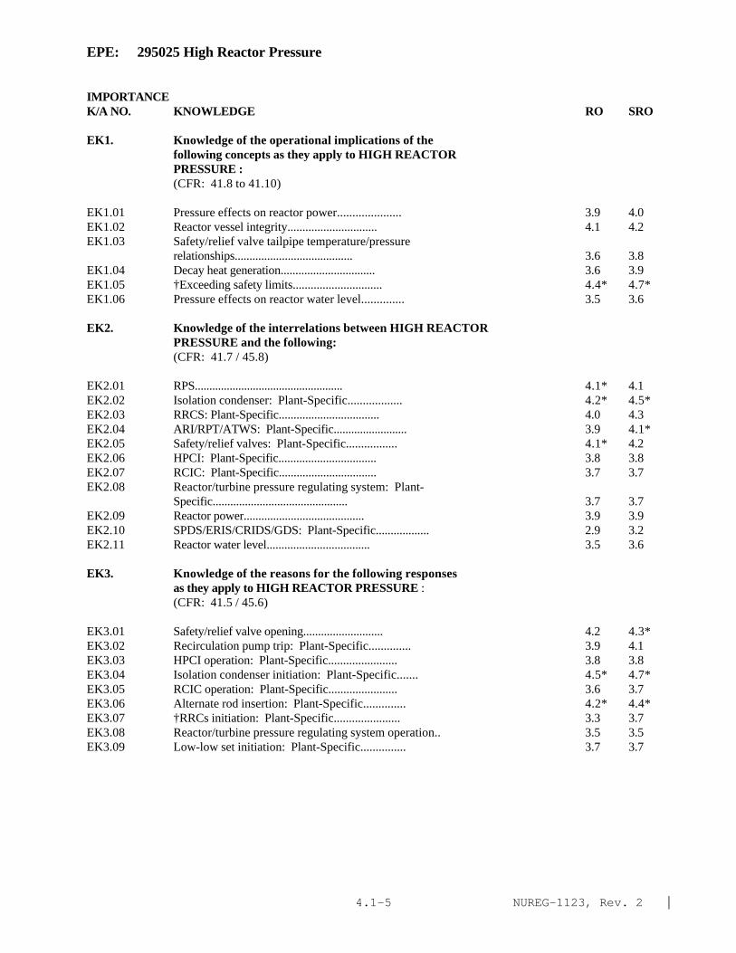
NUREG-1123, Rev. 2 |4.1-5
EPE: 295025 High Reactor Pressure
IMPORTANCE K/A NO. KNOWLEDGE RO SRO
EK1. Knowledge of the operational implications of thefollowing concepts as they apply to HIGH REACTORPRESSURE :(CFR: 41.8 to 41.10)
EK1.01 Pressure effects on reactor power..................... 3.9 4.0EK1.02 Reactor vessel integrity.............................. 4.1 4.2EK1.03 Safety/relief valve tailpipe temperature/pressure
relationships........................................ 3.6 3.8EK1.04 Decay heat generation................................ 3.6 3.9EK1.05 †Exceeding safety limits.............................. 4.4* 4.7*EK1.06 Pressure effects on reactor water level.............. 3.5 3.6
EK2. Knowledge of the interrelations between HIGH REACTORPRESSURE and the following:(CFR: 41.7 / 45.8)
EK2.01 RPS................................................... 4.1* 4.1EK2.02 Isolation condenser: Plant-Specific.................. 4.2* 4.5*EK2.03 RRCS: Plant-Specific.................................. 4.0 4.3EK2.04 ARI/RPT/ATWS: Plant-Specific......................... 3.9 4.1*EK2.05 Safety/relief valves: Plant-Specific................. 4.1* 4.2EK2.06 HPCI: Plant-Specific................................. 3.8 3.8EK2.07 RCIC: Plant-Specific................................. 3.7 3.7EK2.08 Reactor/turbine pressure regulating system: Plant-
Specific.............................................. 3.7 3.7EK2.09 Reactor power......................................... 3.9 3.9EK2.10 SPDS/ERIS/CRIDS/GDS: Plant-Specific.................. 2.9 3.2EK2.11 Reactor water level................................... 3.5 3.6
EK3. Knowledge of the reasons for the following responsesas they apply to HIGH REACTOR PRESSURE :(CFR: 41.5 / 45.6)
EK3.01 Safety/relief valve opening........................... 4.2 4.3*EK3.02 Recirculation pump trip: Plant-Specific.............. 3.9 4.1EK3.03 HPCI operation: Plant-Specific....................... 3.8 3.8EK3.04 Isolation condenser initiation: Plant-Specific....... 4.5* 4.7*EK3.05 RCIC operation: Plant-Specific....................... 3.6 3.7EK3.06 Alternate rod insertion: Plant-Specific.............. 4.2* 4.4*EK3.07 †RRCs initiation: Plant-Specific...................... 3.3 3.7EK3.08 Reactor/turbine pressure regulating system operation.. 3.5 3.5EK3.09 Low-low set initiation: Plant-Specific............... 3.7 3.7
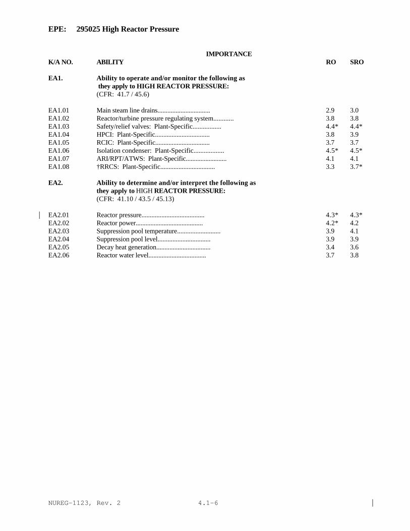
NUREG-1123, Rev. 2 |4.1-6
EPE: 295025 High Reactor Pressure
IMPORTANCE K/A NO. ABILITY RO SRO
EA1. Ability to operate and/or monitor the following as they apply to HIGH REACTOR PRESSURE:(CFR: 41.7 / 45.6)
EA1.01 Main steam line drains................................ 2.9 3.0EA1.02 Reactor/turbine pressure regulating system............ 3.8 3.8EA1.03 Safety/relief valves: Plant-Specific................. 4.4* 4.4*EA1.04 HPCI: Plant-Specific................................. 3.8 3.9EA1.05 RCIC: Plant-Specific................................. 3.7 3.7EA1.06 Isolation condenser: Plant-Specific.................. 4.5* 4.5*EA1.07 ARI/RPT/ATWS: Plant-Specific......................... 4.1 4.1EA1.08 †RRCS: Plant-Specific................................. 3.3 3.7*
EA2. Ability to determine and/or interpret the following asthey apply to HIGH REACTOR PRESSURE:(CFR: 41.10 / 43.5 / 45.13)
EA2.01 Reactor pressure...................................... 4.3* 4.3*|EA2.02 Reactor power......................................... 4.2* 4.2EA2.03 Suppression pool temperature.......................... 3.9 4.1EA2.04 Suppression pool level................................ 3.9 3.9EA2.05 Decay heat generation................................. 3.4 3.6EA2.06 Reactor water level................................... 3.7 3.8

NUREG-1123, Rev. 2 |4.1-7
EPE: 295026 Suppression Pool High Water Temperature
IMPORTANCE K/A NO. KNOWLEDGE RO SRO
EK1. Knowledge of the operational implications of thefollowing concepts as they apply to SUPPRESSION POOLHIGH WATER TEMPERATURE :(CFR: 41.8 to 41.10)
EK1.01 Pump NPSH............................................. 3.0 3.4EK1.02 Steam condensation.................................... 3.5 3.8
EK2. Knowledge of the interrelations between SUPPRESSIONPOOL HIGH WATER TEMPERATURE and the following:(CFR: 41.7 / 45.8)
EK2.01 Suppression pool cooling.............................. 3.9 4.0EK2.02 Suppression pool spray: Plant-Specific............... 3.6 3.8EK2.03 Suppression chamber pressure: Mark-I&II.............. 3.2 3.6EK2.04 SPDS/ERIS/CRIDS/GDS: Plant-Specific.................. 2.5 2.8EK2.05 Containment pressure: Mark-III....................... 3.0 3.3EK2.06 Suppression pool level................................ 3.5 3.7
EK3. Knowledge of the reasons for the following responsesas they apply to SUPPRESSION POOL HIGH WATERTEMPERATURE:(CFR: 41.5 / 45.6)
EK3.01 Emergency/normal depressurization..................... 3.8 4.1EK3.02 Suppression pool cooling.............................. 3.9 4.0EK3.03 Suppression pool spray: Plant-Specific............... 3.5 3.8EK3.04 †SBLC injection........................................ 3.7 4.1*EK3.05 Reactor SCRAM......................................... 3.9 4.1
ABILITY
EA1. Ability to operate and/or monitor the following asthey apply to SUPPRESSION POOL HIGH WATER TEMPERATURE:(CFR: 41.7 / 45.6)
EA1.01 Suppression pool cooling.............................. 4.1 4.1EA1.02 Suppression pool spray: Plant-Specific............... 3.6 3.8EA1.03 Temperature monitoring................................ 3.9* 3.9
EA2. Ability to determine and/or interpret the following asthey apply to SUPPRESSION POOL HIGH WATER TEMPERATURE:(CFR: 41.10 / 43.5 / 45.13)
EA2.01 Suppression pool water temperature.................... 4.1* 4.2*EA2.02 Suppression pool level................................ 3.8 3.9EA2.03 Reactor pressure...................................... 3.9 4.0
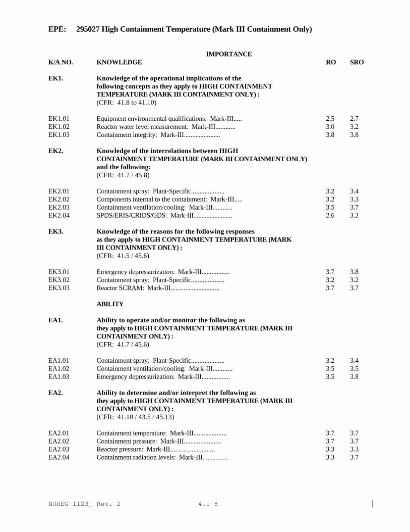
NUREG-1123, Rev. 2 |4.1-8
EPE: 295027 High Containment Temperature (Mark III Containment Only)
IMPORTANCE K/A NO. KNOWLEDGE RO SRO
EK1. Knowledge of the operational implications of thefollowing concepts as they apply to HIGH CONTAINMENTTEMPERATURE (MARK III CONTAINMENT ONLY) :(CFR: 41.8 to 41.10)
EK1.01 Equipment environmental qualifications: Mark-III..... 2.5 2.7EK1.02 Reactor water level measurement: Mark-III............ 3.0 3.2EK1.03 Containment integrity: Mark-III...................... 3.8 3.8
EK2. Knowledge of the interrelations between HIGHCONTAINMENT TEMPERATURE (MARK III CONTAINMENT ONLY)and the following:(CFR: 41.7 / 45.8)
EK2.01 Containment spray: Plant-Specific.................... 3.2 3.4EK2.02 Components internal to the containment: Mark-III..... 3.2 3.3EK2.03 Containment ventilation/cooling: Mark-III............ 3.5 3.7EK2.04 SPDS/ERIS/CRIDS/GDS: Mark-III........................ 2.6 3.2
EK3. Knowledge of the reasons for the following responsesas they apply to HIGH CONTAINMENT TEMPERATURE (MARKIII CONTAINMENT ONLY) :(CFR: 41.5 / 45.6)
EK3.01 Emergency depressurization: Mark-III................. 3.7 3.8EK3.02 Containment spray: Plant-Specific.................... 3.2 3.2EK3.03 Reactor SCRAM: Mark-III.............................. 3.7 3.7
ABILITY
EA1. Ability to operate and/or monitor the following asthey apply to HIGH CONTAINMENT TEMPERATURE (MARK IIICONTAINMENT ONLY) :(CFR: 41.7 / 45.6)
EA1.01 Containment spray: Plant-Specific.................... 3.2 3.4EA1.02 Containment ventilation/cooling: Mark-III............ 3.5 3.5EA1.03 Emergency depressurization: Mark-III................. 3.5 3.8
EA2. Ability to determine and/or interpret the following asthey apply to HIGH CONTAINMENT TEMPERATURE (MARK IIICONTAINMENT ONLY) :(CFR: 41.10 / 43.5 / 45.13)
EA2.01 Containment temperature: Mark-III.................... 3.7 3.7EA2.02 Containment pressure: Mark-III....................... 3.7 3.7EA2.03 Reactor pressure: Mark-III........................... 3.3 3.3EA2.04 Containment radiation levels: Mark-III............... 3.3 3.7
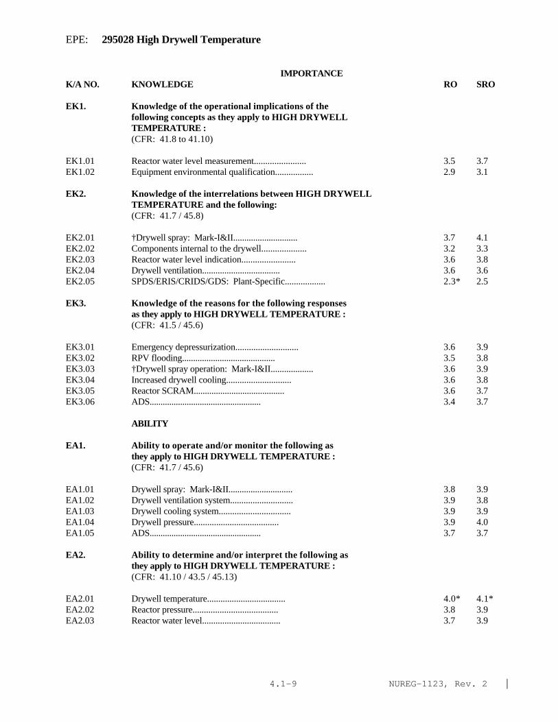
NUREG-1123, Rev. 2 |4.1-9
EPE: 295028 High Drywell Temperature
IMPORTANCE K/A NO. KNOWLEDGE RO SRO
EK1. Knowledge of the operational implications of thefollowing concepts as they apply to HIGH DRYWELLTEMPERATURE :(CFR: 41.8 to 41.10)
EK1.01 Reactor water level measurement....................... 3.5 3.7EK1.02 Equipment environmental qualification................. 2.9 3.1
EK2. Knowledge of the interrelations between HIGH DRYWELLTEMPERATURE and the following:(CFR: 41.7 / 45.8)
EK2.01 †Drywell spray: Mark-I&II............................. 3.7 4.1EK2.02 Components internal to the drywell.................... 3.2 3.3EK2.03 Reactor water level indication........................ 3.6 3.8EK2.04 Drywell ventilation................................... 3.6 3.6EK2.05 SPDS/ERIS/CRIDS/GDS: Plant-Specific.................. 2.3* 2.5
EK3. Knowledge of the reasons for the following responsesas they apply to HIGH DRYWELL TEMPERATURE :(CFR: 41.5 / 45.6)
EK3.01 Emergency depressurization............................ 3.6 3.9EK3.02 RPV flooding.......................................... 3.5 3.8EK3.03 †Drywell spray operation: Mark-I&II................... 3.6 3.9EK3.04 Increased drywell cooling............................. 3.6 3.8EK3.05 Reactor SCRAM......................................... 3.6 3.7EK3.06 ADS................................................... 3.4 3.7
ABILITY
EA1. Ability to operate and/or monitor the following asthey apply to HIGH DRYWELL TEMPERATURE :(CFR: 41.7 / 45.6)
EA1.01 Drywell spray: Mark-I&II............................. 3.8 3.9EA1.02 Drywell ventilation system............................ 3.9 3.8EA1.03 Drywell cooling system................................ 3.9 3.9EA1.04 Drywell pressure...................................... 3.9 4.0EA1.05 ADS................................................... 3.7 3.7
EA2. Ability to determine and/or interpret the following asthey apply to HIGH DRYWELL TEMPERATURE :(CFR: 41.10 / 43.5 / 45.13)
EA2.01 Drywell temperature................................... 4.0* 4.1*EA2.02 Reactor pressure...................................... 3.8 3.9EA2.03 Reactor water level................................... 3.7 3.9

NUREG-1123, Rev. 2 |4.1-10
EPE: 295028 High Drywell Temperature
IMPORTANCE K/A NO. ABILITY RO SRO
EA2.04 Drywell pressure...................................... 4.1 4.2EA2.05 Torus/suppression chamber pressure: Plant-Specific... 3.6 3.8EA2.06 Torus/suppression chamber air space temperature:
Plant-Specific........................................ 3.4 3.7

NUREG-1123, Rev. 2 |4.1-11
EPE: 295029 High Suppression Pool Water Level
IMPORTANCE K/A NO. KNOWLEDGE RO SRO
EK1. Knowledge of the operational implications of thefollowing concepts as they apply to HIGH SUPPRESSIONPOOL WATER LEVEL :(CFR: 41.8 to 41.10)
EK1.01 Containment integrity................................. 3.4 3.7
EK2. Knowledge of the interrelations between HIGHSUPPRESSION POOL WATER LEVEL and the following:(CFR: 41.7 / 45.8)
EK2.01 RHR/LPCI.............................................. 3.0 3.3EK2.02 HPCI: Plant-Specific................................. 3.4 3.6EK2.03 HPCS: Plant-Specific................................. 3.3 3.5EK2.04 Suppression pool cleanup system: Plant-Specific...... 2.4* 2.4*EK2.05 Containment/drywell vacuum breakers................... 3.1 3.3EK2.06 SRV's and discharge piping............................ 3.4 3.5EK2.07 Drywell/containment water level....................... 3.1 3.2EK2.08 Drywell/suppression chamber ventilation............... 2.6 2.9EK2.09 RCIC: Plant-Specific................................. 3.1 3.2
EK3. Knowledge of the reasons for the following responsesas they apply to HIGH SUPPRESSION POOL WATER LEVEL :(CFR: 41.5 / 45.6)
EK3.01 Emergency depressurization............................ 3.5 3.9*EK3.02 Lowering suppression pool water level................. 3.6 4.0EK3.03 Reactor SCRAM......................................... 3.4 3.5
ABILITY
EA1. Ability to operate and/or monitor the following asthey apply to HIGH SUPPRESSION POOL WATER LEVEL :(CFR: 41.7 / 45.6)
EA1.01 HPCI: Plant-Specific................................. 3.4* 3.5EA1.02 HPCS: Plant-Specific................................. 3.1 3.1EA1.03 RHR/LPCI.............................................. 2.9 3.0EA1.04 RCIC: Plant-Specific................................. 3.4 3.5
EA2. Ability to determine and/or interpret the following asthey apply to HIGH SUPPRESSION POOL WATER LEVEL :(CFR: 41.10 / 43.5 / 45.13)
EA2.01 Suppression pool water level.......................... 3.9* 3.9* |EA2.02 Reactor pressure...................................... 3.5 3.6EA2.03 Drywell/containment water level....................... 3.4 3.5

NUREG-1123, Rev. 2 |4.1-12
EPE: 295030 Low Suppression Pool Water Level
IMPORTANCE K/A NO. KNOWLEDGE RO SRO
EK1. Knowledge of the operational implications of thefollowing concepts as they apply to LOW SUPPRESSIONPOOL WATER LEVEL:(CFR: 41.8 to 41.10)
EK1.01 Steam condensation.................................... 3.8* 4.1*EK1.02 Pump NPSH............................................. 3.5 3.8EK1.03 Heat capacity......................................... 3.8 4.1*
EK2. Knowledge of the interrelations between LOWSUPPRESSION POOL WATER LEVEL and the following:(CFR: 41.7 / 45.8)
EK2.01 HPCI: Plant-Specific................................. 3.8 3.9EK2.02 RCIC: Plant-Specific................................. 3.7 3.8EK2.03 LPCS.................................................. 3.8 3.9EK2.04 RHR/LPCI.............................................. 3.7 3.8EK2.05 HPCS: Plant-Specific................................. 3.8 3.9EK2.06 Suppression pool make-up: Mark-III................... 3.9* 3.9*EK2.07 Downcomer/ horizontal vent submergence................ 3.5 3.8EK2.08 SRV discharge submergence............................. 3.5 3.8EK2.09 SPDS/ERIS/CRIDS/GDS: Plant-Specific.................. 2.5 2.8
EK3. Knowledge of the reasons for the following responsesas they apply to LOW SUPPRESSION POOL WATER LEVEL:(CFR: 41.5 / 45.6)
EK3.01 Emergency depressurization............................ 3.8 4.1EK3.02 HPCI operation: Plant-Specific....................... 3.5 3.7EK3.03 RCIC operation: Plant-Specific....................... 3.6 3.7EK3.04 HPCS operation: Plant-Specific....................... 3.5 3.5EK3.05 Suppression pool make-up operation: Mark-III......... 3.6 3.6EK3.06 Reactor SCRAM......................................... 3.6 3.8EK3.07 NPSH considerations for ECCS pumps.................... 3.5 3.8
ABILITY
EA1. Ability to operate and/or monitor the following asthey apply to LOW SUPPRESSION POOL WATER LEVEL:(CFR: 41.7 / 45.6)
EA1.01 ECCS systems (NPSH considerations): Plant-Specific... 3.6 3.8EA1.02 RCIC: Plant-Specific................................. 3.4 3.5EA1.03 HPCS: Plant-Specific................................. 3.4 3.4EA1.04 Suppression pool make-up system: Mark-III............ 4.0 4.0EA1.05 HPCI.................................................. 3.5 3.5

NUREG-1123, Rev. 2 |4.1-13
EPE: 295030 Low Suppression Pool Water Level
IMPORTANCE K/A NO. ABILITY RO SRO
EA1.06 Condensate storage and transfer (make-up to thesuppression pool): Plant-Specific.................... 3.4 3.4
EA2. Ability to determine and/or interpret the following asthey apply to LOW SUPPRESSION POOL WATER LEVEL :(CFR: 41.10 / 43.5 / 45.13)
EA2.01 Suppression pool level................................ 4.1* 4.2*EA2.02 Suppression pool temperature.......................... 3.9 3.9EA2.03 Reactor pressure...................................... 3.7 3.9EA2.04 Drywell/ suppression chamber differential pressure:
Mark-I&II............................................. 3.5 3.7

NUREG-1123, Rev. 2 |4.1-14
EPE: 295031 Reactor Low Water Level
IMPORTANCE K/A NO. KNOWLEDGE RO SRO
EK1. Knowledge of the operational implications of thefollowing concepts as they apply to REACTOR LOW WATERLEVEL :(CFR: 41.8 to 41.10)
EK1.01 Adequate core cooling................................. 4.6* 4.7*EK1.02 Natural circulation: Plant-Specific.................. 3.8 4.1EK1.03 Water level effects on reactor power.................. 3.7 4.1
EK2. Knowledge of the interrelations between REACTOR LOWWATER LEVEL and the following:(CFR: 41.7 / 45.8)
EK2.01 Reactor water level indication........................ 4.4* 4.4*EK2.02 Reactor pressure...................................... 3.8 3.9EK2.03 Low pressure core spray............................... 4.2 4.3*EK2.04 Reactor core isolation cooling: Plant-Specific....... 4.0 4.1EK2.05 Low pressure coolant injection (RHR).................. 4.2 4.3EK2.06 High pressure (feedwater) coolant injection
(FWCI/HPCI): Plant-Specific.......................... 4.1 4.2EK2.07 High pressure core spray: Plant-Specific............. 4.0 4.1EK2.08 Automatic depressurization system..................... 4.2* 4.3*EK2.09 Recirculation system: Plant-Specific................. 3.3 3.4EK2.10 Redundant reactivity control: Plant-Specific......... 4.0 4.0EK2.11 Reactor protection system............................. 4.4* 4.4*EK2.12 Primary containment isolation system/ Nuclear steam
supply shutoff........................................ 4.5* 4.5*EK2.13 ARI/RPT/ATWS: Plant-Specific......................... 4.1 4.2EK2.14 Emergency generators.................................. 3.9 4.0EK2.15 A.C. distribution: Plant-Specific.................... 3.2 3.2EK2.16 Reactor water level control........................... 4.1* 4.1
EK3. Knowledge of the reasons for the following responsesas they apply to REACTOR LOW WATER LEVEL :(CFR: 41.5 / 45.6)
EK3.01 Automatic depressurization system actuation........... 3.9 4.2*EK3.02 Core coverage......................................... 4.4* 4.7*EK3.03 Spray cooling......................................... 4.1 4.4*EK3.04 Steam cooling......................................... 4.0 4.3*EK3.05 Emergency depressurization............................ 4.2* 4.3*

NUREG-1123, Rev. 2 |4.1-15
EPE: 295031 Reactor Low Water Level
IMPORTANCE K/A NO. KNOWLEDGE RO SRO
EA1. Ability to operate and/or monitor the following asthey apply to REACTOR LOW WATER LEVEL :(CFR: 41.7 / 45.6)
EA1.01 Low pressure coolant injection (RHR): Plant-Specific. 4.4* 4.4*EA1.02 High pressure (feedwater) coolant injection: Plant-
Specific.............................................. 4.5* 4.5*EA1.03 Low pressure core spray............................... 4.4* 4.4*EA1.04 High pressure core spray: Plant-Specific............. 4.3* 4.2EA1.05 Reactor core isolation system: Plant-Specific........ 4.3* 4.3*EA1.06 Automatic depressurization system..................... 4.4* 4.4*EA1.07 Safety/relief valves.................................. 3.7* 3.7*EA1.08 Alternate injection systems: Plant-specific.......... 3.8 3.9EA1.09 Isolation condenser: Plant-Specific.................. 3.3* 3.5*EA1.10 Control rod drive..................................... 3.6 3.7EA1.11 Condensate............................................ 4.1 4.1EA1.12 Feedwater............................................. 3.9 4.1*EA1.13 Reactor water level control........................... 4.3* 4.3*
EA2. Ability to determine and/or interpret the followingas they apply to REACTOR LOW WATER LEVEL :(CFR: 41.10 / 43.5 / 45.13)
EA2.01 Reactor water level............................ 4.6* 4.6*EA2.02 Reactor power.................................. 4.0 4.2*EA2.03 Reactor pressure............................... 4.2* 4.2*EA2.04 Adequate core cooling.......................... 4.6* 4.8*

NUREG-1123, Rev. 2 |4.1-16
EPE: 295032 High Secondary Containment Area Temperature
IMPORTANCE K/A NO. KNOWLEDGE RO SRO
EK1. Knowledge of the operational implications of thefollowing concepts as they apply to HIGH SECONDARYCONTAINMENT AREA TEMPERATURE: (CFR: 41.8 to 41.10)
EK1.01 Personnel protection.................................. 3.6 3.8EK1.02 †Radiation releases.................................... 3.6 4.0EK1.03 Secondary containment leakage detection: Plant-
Specific.............................................. 3.5? 3.9?EK1.04 Impact of operating environment on components......... 3.1 3.6
EK2. Knowledge of the interrelations between HIGH SECONDARYCONTAINMENT AREA TEMPERATURE and the following:(CFR: 41.7 / 45.8)
EK2.01 Area/room coolers..................................... 3.5 3.6EK2.02 Secondary containment ventilation..................... 3.6 3.7EK2.03 Fire protection system................................ 3.3 3.4EK2.04 PCIS/NSSSS............................................ 3.6 3.8EK2.05 Temperature sensitive instrumentation................. 3.2 3.4EK2.06 Area temperature monitoring system.................... 3.3 3.4EK2.07 Leak detection system concept: Plant-Specific........ 3.6 3.8EK2.08 Systems required for safe shut-down................... 3.8 3.9
EK3. Knowledge of the reasons for the following responsesas they apply to HIGH SECONDARY CONTAINMENT AREATEMPERATURE :(CFR: 41.5 / 45.6)
EK3.01 Emergency/normal depressurization..................... 3.5 3.8EK3.02 Reactor SCRAM......................................... 3.6 3.8EK3.03 Isolating affected systems............................ 3.8 3.9*
ABILITY
EA1. Ability to operate and/or monitor the following asthey apply to HIGH SECONDARY CONTAINMENT AREATEMPERATURE :(CFR: 41.7 / 45.6)
EA1.01 Area temperature monitoring system.................... 3.6 3.7EA1.02 Leak detection system concept: Plant-Specific........ 3.4 3.5EA1.03 Secondary containment ventilation..................... 3.7 3.7EA1.04 Fire protection system................................ 3.3 3.4EA1.05 Affected systems so as to isolate damaged portions.... 3.7 3.9
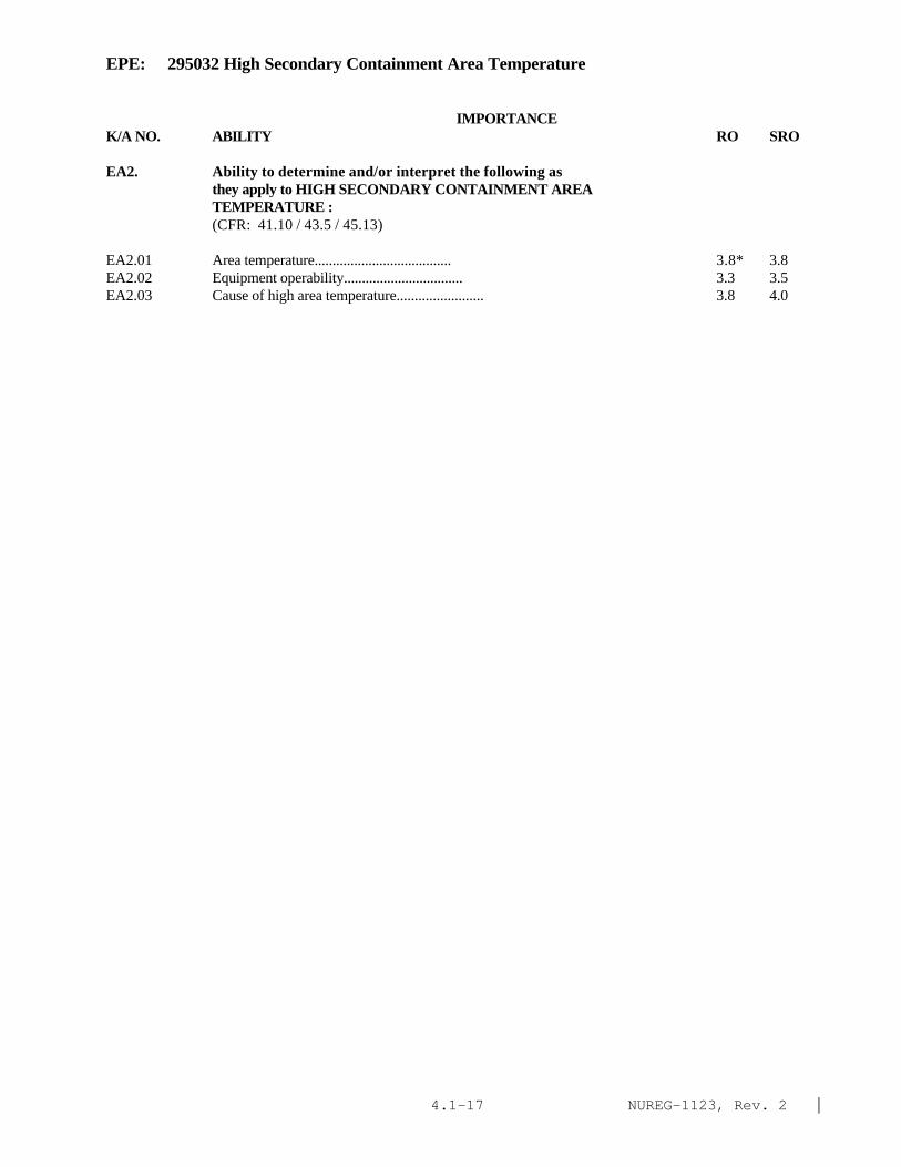
NUREG-1123, Rev. 2 |4.1-17
EPE: 295032 High Secondary Containment Area Temperature
IMPORTANCE K/A NO. ABILITY RO SRO
EA2. Ability to determine and/or interpret the following asthey apply to HIGH SECONDARY CONTAINMENT AREATEMPERATURE :(CFR: 41.10 / 43.5 / 45.13)
EA2.01 Area temperature...................................... 3.8* 3.8EA2.02 Equipment operability................................. 3.3 3.5EA2.03 Cause of high area temperature........................ 3.8 4.0

NUREG-1123, Rev. 2 |4.1-18
EPE: 295033 High Secondary Containment Area Radiation Levels
IMPORTANCE K/A NO. KNOWLEDGE RO SRO
EK1. Knowledge of the operational implications of thefollowing concepts as they apply to HIGH SECONDARYCONTAINMENT AREA RADIATION LEVELS :(CFR: 41.8 to 41.10)
EK1.01 Component environmental qualifications................ 2.4 2.8*EK1.02 Personnel protection.................................. 3.9 4.2*EK1.03 †Radiation releases.................................... 3.9 4.2*
EK2. Knowledge of the interrelations between HIGH SECONDARYCONTAINMENT AREA RADIATION LEVELS and the following:(CFR: 41.7 / 45.8)
EK2.01 Area radiation monitoring system...................... 3.8 4.0EK2.02 Process radiation monitoring system................... 3.8 4.1EK2.03 Secondary containment ventilation: Plant-Specific.... 3.7 3.9EK2.04 Standby gas treatment system/FRVS..................... 3.9 4.2
EK3. Knowledge of the reasons for the following responsesas they apply to HIGH SECONDARY CONTAINMENT AREARADIATION LEVELS :(CFR: 41.5 / 45.6)
EK3.01 Emergency depressurization............................ 3.3 3.5EK3.02 Reactor SCRAM......................................... 3.5 3.6EK3.03 Isolating affected systems............................ 3.8 3.9EK3.04 Personnel evacuation.................................. 4.0 4.4*EK3.05 Emergency plan........................................ 3.6 4.5*
ABILITY
EA1. Ability to operate and/or monitor the following as they apply to HIGH SECONDARY CONTAINMENT AREA
RADIATION LEVELS :(CFR: 41.7 / 45.6)
EA1.01 Area radiation monitoring system...................... 3.9 4.0EA1.02 Process radiation monitoring system................... 3.7 3.8EA1.03 Secondary containment ventilation..................... 3.8 3.8EA1.04 SBGT/FRVS............................................. 4.2* 4.2EA1.05 Affected systems so as to isolate damaged portions.... 3.9 4.0EA1.06 Portable radiation monitoring instruments............. 2.9* 3.1*EA1.07 Personnel dosimetry................................... 3.5 3.6EA1.08 Control room ventilation: Plant-Specific............. 3.6 3.8
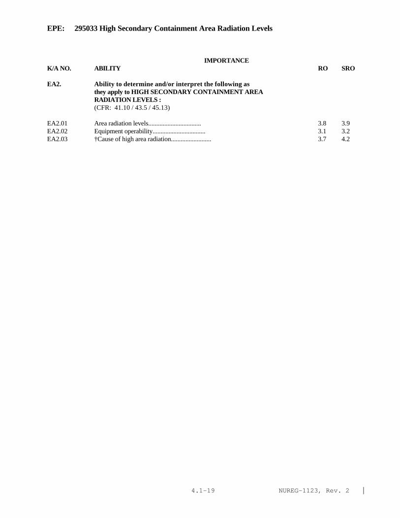
NUREG-1123, Rev. 2 |4.1-19
EPE: 295033 High Secondary Containment Area Radiation Levels
IMPORTANCE K/A NO. ABILITY RO SRO
EA2. Ability to determine and/or interpret the following asthey apply to HIGH SECONDARY CONTAINMENT AREARADIATION LEVELS :(CFR: 41.10 / 43.5 / 45.13)
EA2.01 Area radiation levels................................. 3.8 3.9EA2.02 Equipment operability................................. 3.1 3.2EA2.03 †Cause of high area radiation......................... 3.7 4.2

NUREG-1123, Rev. 2 |4.1-20
EPE: 295034 Secondary Containment Ventilation High Radiation
IMPORTANCE K/A NO. KNOWLEDGE RO SRO
EK1. Knowledge of the operational implications of thefollowing concepts as they apply to SECONDARYCONTAINMENT VENTILATION HIGH RADIATION :(CFR: 41.8 to 41.10)
EK1.01 Personnel protection.................................. 3.8 4.1EK1.02 †Radiation releases.................................... 4.1 4.4*
EK2. Knowledge of the interrelations between SECONDARYCONTAINMENT VENTILATION HIGH RADIATION and thefollowing:(CFR: 41.7 / 45.8)
EK2.01 Process radiation monitoring system................... 3.9 4.2EK2.02 Area radiation monitoring system...................... 3.8 3.9EK2.03 SBGT/FRVS: Plant-Specific............................ 4.3* 4.5*EK2.04 Secondary containment ventilation..................... 3.9 3.9EK2.05 Fuel building ventilation: Mark-III.................. 3.5 3.7EK2.06 PCIS/NSSSS: Plant-Specific........................... 3.9 4.2
EK3. Knowledge of the reasons for the following responsesas they apply to SECONDARY CONTAINMENT VENTILATIONHIGH RADIATION :(CFR: 41.5 / 45.6)
EK3.01 Isolating secondary containment ventilation........... 3.8 4.1EK3.02 Starting SBGT/FRVS: Plant-Specific................... 4.1 4.1EK3.03 Personnel evacuation.................................. 4.0* 4.4*EK3.04 Fuel building ventilation: Plant-Specific............ 3.7 3.8EK3.05 Manual SCRAM and depressurization: Plant-Specific.... 3.6 3.9|
ABILITY
EA1. Ability to operate and/or monitor the following asthey apply to SECONDARY CONTAINMENT VENTILATION HIGHRADIATION :(CFR: 41.7 / 45.6)
EA1.01 Area radiation monitoring system...................... 3.8 3.8EA1.02 Process radiation monitoring system................... 3.9 4.0EA1.03 Secondary containment ventilation..................... 4.0 3.9EA1.04 SBGT/FRVS: Plant-Specific............................ 4.1* 4.2*EA1.05 Fuel building ventilation: Plant-Specific............ 3.8 3.8

NUREG-1123, Rev. 2 |4.1-21
EPE: 295034 Secondary Containment Ventilation High Radiation
IMPORTANCE K/A NO. ABILITY RO SRO
EA2. Ability to determine and/or interpret the following asthey apply to SECONDARY CONTAINMENT VENTILATION HIGHRADIATION :(CFR: 41.10 / 43.5 / 45.13)
EA2.01 Ventilation radiation levels.......................... 3.8 4.2EA2.02 Cause of high radiation levels........................ 3.7 4.2*
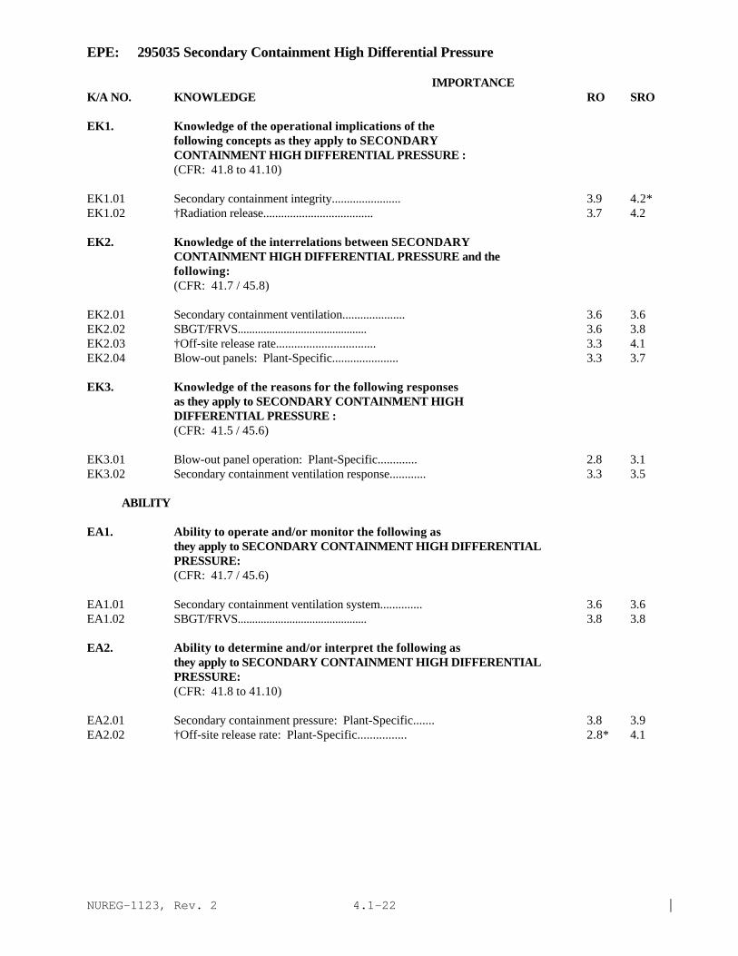
NUREG-1123, Rev. 2 |4.1-22
EPE: 295035 Secondary Containment High Differential Pressure
IMPORTANCE K/A NO. KNOWLEDGE RO SRO
EK1. Knowledge of the operational implications of thefollowing concepts as they apply to SECONDARYCONTAINMENT HIGH DIFFERENTIAL PRESSURE :(CFR: 41.8 to 41.10)
EK1.01 Secondary containment integrity....................... 3.9 4.2*EK1.02 †Radiation release..................................... 3.7 4.2
EK2. Knowledge of the interrelations between SECONDARYCONTAINMENT HIGH DIFFERENTIAL PRESSURE and thefollowing:(CFR: 41.7 / 45.8)
EK2.01 Secondary containment ventilation..................... 3.6 3.6EK2.02 SBGT/FRVS............................................. 3.6 3.8EK2.03 †Off-site release rate................................. 3.3 4.1EK2.04 Blow-out panels: Plant-Specific...................... 3.3 3.7
EK3. Knowledge of the reasons for the following responsesas they apply to SECONDARY CONTAINMENT HIGHDIFFERENTIAL PRESSURE :(CFR: 41.5 / 45.6)
EK3.01 Blow-out panel operation: Plant-Specific............. 2.8 3.1EK3.02 Secondary containment ventilation response............ 3.3 3.5
ABILITY
EA1. Ability to operate and/or monitor the following asthey apply to SECONDARY CONTAINMENT HIGH DIFFERENTIALPRESSURE:(CFR: 41.7 / 45.6)
EA1.01 Secondary containment ventilation system.............. 3.6 3.6EA1.02 SBGT/FRVS............................................. 3.8 3.8
EA2. Ability to determine and/or interpret the following asthey apply to SECONDARY CONTAINMENT HIGH DIFFERENTIALPRESSURE:(CFR: 41.8 to 41.10)
EA2.01 Secondary containment pressure: Plant-Specific....... 3.8 3.9EA2.02 †Off-site release rate: Plant-Specific................ 2.8* 4.1
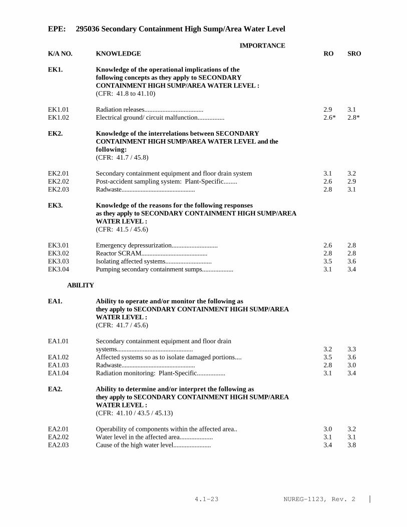
NUREG-1123, Rev. 2 |4.1-23
EPE: 295036 Secondary Containment High Sump/Area Water Level
IMPORTANCE K/A NO. KNOWLEDGE RO SRO
EK1. Knowledge of the operational implications of thefollowing concepts as they apply to SECONDARYCONTAINMENT HIGH SUMP/AREA WATER LEVEL :(CFR: 41.8 to 41.10)
EK1.01 Radiation releases.................................... 2.9 3.1EK1.02 Electrical ground/ circuit malfunction................ 2.6* 2.8*
EK2. Knowledge of the interrelations between SECONDARYCONTAINMENT HIGH SUMP/AREA WATER LEVEL and thefollowing:(CFR: 41.7 / 45.8)
EK2.01 Secondary containment equipment and floor drain system 3.1 3.2EK2.02 Post-accident sampling system: Plant-Specific........ 2.6 2.9EK2.03 Radwaste.............................................. 2.8 3.1
EK3. Knowledge of the reasons for the following responsesas they apply to SECONDARY CONTAINMENT HIGH SUMP/AREAWATER LEVEL :(CFR: 41.5 / 45.6)
EK3.01 Emergency depressurization............................ 2.6 2.8EK3.02 Reactor SCRAM......................................... 2.8 2.8EK3.03 Isolating affected systems............................ 3.5 3.6EK3.04 Pumping secondary containment sumps................... 3.1 3.4
ABILITY
EA1. Ability to operate and/or monitor the following asthey apply to SECONDARY CONTAINMENT HIGH SUMP/AREAWATER LEVEL :(CFR: 41.7 / 45.6)
EA1.01 Secondary containment equipment and floor drainsystems............................................... 3.2 3.3
EA1.02 Affected systems so as to isolate damaged portions.... 3.5 3.6EA1.03 Radwaste.............................................. 2.8 3.0EA1.04 Radiation monitoring: Plant-Specific................. 3.1 3.4
EA2. Ability to determine and/or interpret the following asthey apply to SECONDARY CONTAINMENT HIGH SUMP/AREAWATER LEVEL :(CFR: 41.10 / 43.5 / 45.13)
EA2.01 Operability of components within the affected area.. 3.0 3.2EA2.02 Water level in the affected area.................... 3.1 3.1EA2.03 Cause of the high water level....................... 3.4 3.8
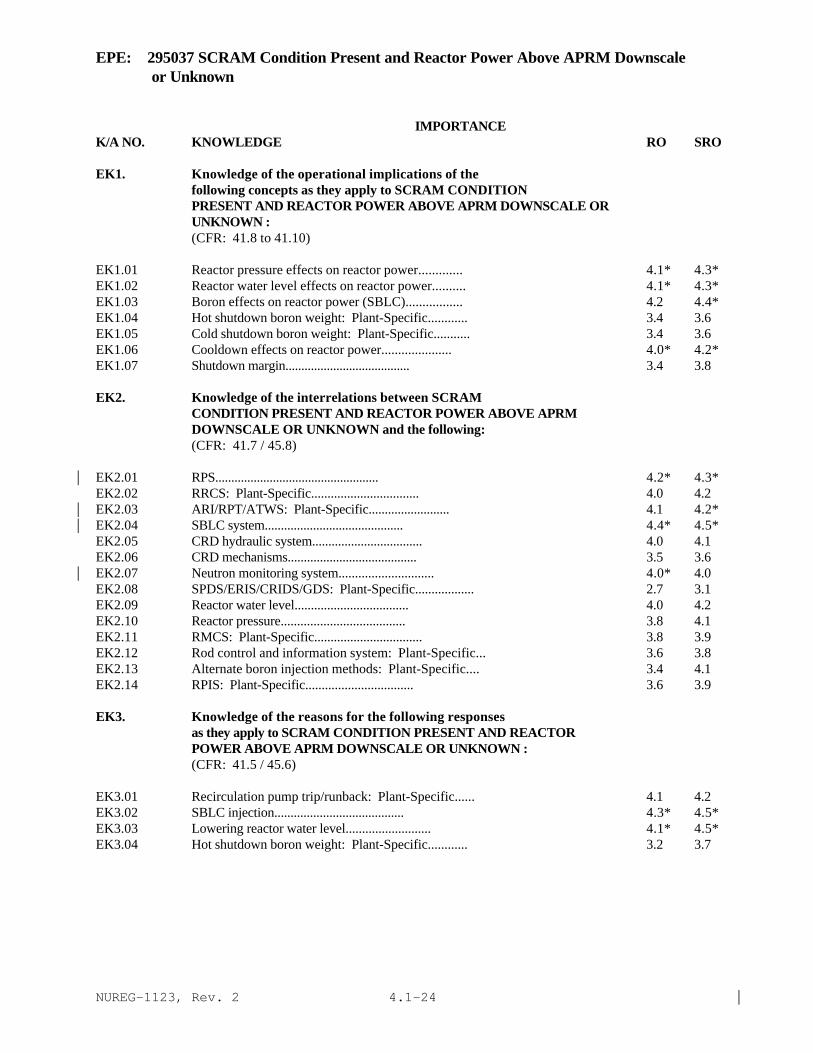
NUREG-1123, Rev. 2 |4.1-24
EPE: 295037 SCRAM Condition Present and Reactor Power Above APRM Downscale or Unknown
IMPORTANCE K/A NO. KNOWLEDGE RO SRO
EK1. Knowledge of the operational implications of thefollowing concepts as they apply to SCRAM CONDITIONPRESENT AND REACTOR POWER ABOVE APRM DOWNSCALE ORUNKNOWN :(CFR: 41.8 to 41.10)
EK1.01 Reactor pressure effects on reactor power............. 4.1* 4.3*EK1.02 Reactor water level effects on reactor power.......... 4.1* 4.3*EK1.03 Boron effects on reactor power (SBLC)................. 4.2 4.4*EK1.04 Hot shutdown boron weight: Plant-Specific............ 3.4 3.6EK1.05 Cold shutdown boron weight: Plant-Specific........... 3.4 3.6EK1.06 Cooldown effects on reactor power..................... 4.0* 4.2*EK1.07 Shutdown margin....................................... 3.4 3.8
EK2. Knowledge of the interrelations between SCRAMCONDITION PRESENT AND REACTOR POWER ABOVE APRMDOWNSCALE OR UNKNOWN and the following:(CFR: 41.7 / 45.8)
EK2.01 RPS................................................... 4.2* 4.3*|EK2.02 RRCS: Plant-Specific................................. 4.0 4.2EK2.03 ARI/RPT/ATWS: Plant-Specific......................... 4.1 4.2*|EK2.04 SBLC system........................................... 4.4* 4.5*|EK2.05 CRD hydraulic system.................................. 4.0 4.1EK2.06 CRD mechanisms........................................ 3.5 3.6EK2.07 Neutron monitoring system............................. 4.0* 4.0|EK2.08 SPDS/ERIS/CRIDS/GDS: Plant-Specific.................. 2.7 3.1EK2.09 Reactor water level................................... 4.0 4.2EK2.10 Reactor pressure...................................... 3.8 4.1EK2.11 RMCS: Plant-Specific................................. 3.8 3.9EK2.12 Rod control and information system: Plant-Specific... 3.6 3.8EK2.13 Alternate boron injection methods: Plant-Specific.... 3.4 4.1EK2.14 RPIS: Plant-Specific................................. 3.6 3.9
EK3. Knowledge of the reasons for the following responsesas they apply to SCRAM CONDITION PRESENT AND REACTORPOWER ABOVE APRM DOWNSCALE OR UNKNOWN :(CFR: 41.5 / 45.6)
EK3.01 Recirculation pump trip/runback: Plant-Specific...... 4.1 4.2EK3.02 SBLC injection........................................ 4.3* 4.5*EK3.03 Lowering reactor water level.......................... 4.1* 4.5*EK3.04 Hot shutdown boron weight: Plant-Specific............ 3.2 3.7

NUREG-1123, Rev. 2 |4.1-25
EPE: 295037 SCRAM Condition Present and Reactor Power Above APRM Downscale or Unknown
IMPORTANCE K/A NO. KNOWLEDGE RO SRO
EK3.05 Cold shutdown boron weight: Plant-Specific........... 3.2 3.7EK3.06 Maintaining heat sinks external to the containment.... 3.8 4.1EK3.07 Various alternate methods of control rod insertion:
Plant-Specific........................................ 4.2 4.3*EK3.08 ATWS circuitry: Plant-Specific....................... 3.6* 3.9*
ABILITY
EA1. Ability to operate and/or monitor the following as they apply to SCRAM CONDITION PRESENT AND REACTOR
POWER ABOVE APRM DOWNSCALE OR UNKNOWN :(CFR: 41.7 / 45.6)
EA1.01 Reactor Protection System............................. 4.6* 4.6*EA1.02 RRCS: Plant-Specific................................. 3.8 4.0EA1.03 ARI/RPT/ATWS: Plant-Specific......................... 4.1* 4.1*EA1.04 SBLC.................................................. 4.5* 4.5*EA1.05 CRD hydraulics systems................................ 3.9 4.0EA1.06 Neutron monitoring system............................. 4.1* 4.1EA1.07 RMCS: Plant-Specific................................. 3.9 4.0EA1.08 Rod control and information system: Plant-Specific... 3.6 3.6EA1.09 SPDS/ERIS/CRIDS/GDS: Plant-Specific.................. 2.8* 3.0EA1.10 Alternate boron injection methods: Plant-Specific.... 3.7 3.9EA1.11 PCIS/NSSSS............................................ 3.5 3.6
EA2. Ability to determine and/or interpret the following asthey apply to SCRAM CONDITION PRESENT AND REACTORPOWER ABOVE APRM DOWNSCALE OR UNKNOWN :(CFR: 41.10 / 43.5 / 45.13)
EA2.01 Reactor power......................................... 4.2* 4.3*EA2.02 Reactor water level................................... 4.1* 4.2*EA2.03 SBLC tank level....................................... 4.3* 4.4*EA2.04 Suppression pool temperature.......................... 4.0* 4.1*EA2.05 Control rod position.................................. 4.2* 4.3*EA2.06 Reactor pressure...................................... 4.0 4.1EA2.07 Containment conditions/isolations..................... 4.0 4.2*

NUREG-1123, Rev. 2 |4.1-26
EPE: 295038 High Off-Site Release Rate
IMPORTANCE K/A NO. KNOWLEDGE RO SRO
EK1. Knowledge of the operational implications of thefollowing concepts as they apply to HIGH OFF-SITERELEASE RATE :(CFR: 41.8 to 41.10)
EK1.01 Biological effects of radioisotope ingestion.......... 2.5 3.1EK1.02 †Protection of the general public...................... 4.2* 4.4*EK1.03 †Meteorological effects on off-site release............ 2.8 3.8
EK2. Knowledge of the interrelations between HIGH OFF-SITERELEASE RATE and the following:(CFR: 41.7 / 45.8)
EK2.01 Radwaste.............................................. 3.1 3.4EK2.02 Offgas system......................................... 3.6 3.8EK2.03 Plant ventilation systems............................. 3.6 3.8EK2.04 Stack-gas monitoring system: Plant-Specific.......... 3.9 4.2EK2.05 †Site emergency plan................................... 3.7 4.7*EK2.06 Process liquid radiation monitoring system............ 3.4 3.7EK2.07 Control room ventilation.............................. 3.5 3.7EK2.08 SPDS/ERIS/CRIDS/GDS: Plant-Specific.................. 2.6 3.1EK2.09 Post accident sample system (PASS): Plant-Specific... 2.9* 3.5*EK2.10 Condenser air removal system.......................... 3.2 3.4EK2.11 MSIV leakage control: Plant-Specific................. 3.1 3.4EK2.12 Feedwater leakage control: BWR-6..................... 3.5 3.8
EK3. Knowledge of the reasons for the following responsesas they apply to HIGH OFF-SITE RELEASE RATE:(CFR: 41.5 / 45.6)
EK3.01 †Implementation of site emergency plan................. 3.6 4.5*EK3.02 System isolations..................................... 3.9 4.2EK3.03 Control room ventilation isolation: Plant-Specific... 3.7 3.9EK3.04 †Emergency depressurization............................ 3.6 3.9
ABILITY
EA1. Ability to operate and/or monitor the following as they apply to HIGH OFF-SITE RELEASE RATE :
(CFR: 41.7 / 45.6)
EA1.01 Stack-gas monitoring system: Plant-Specific.......... 3.9 4.2EA1.02 †Meteorological instrumentation........................ 3.0* 3.8EA1.03 Process liquid radiation monitoring system............ 3.7 3.9EA1.04 SPDS/ERIS/CRIDS/GDS: Plant-Specific.................. 2.8 3.2EA1.05 Post accident sample system (PASS): Plant-Specific... 3.0* 3.5*EA1.06 Plant ventilation..................................... 3.5 3.6EA1.07 Control room ventilation: Plant-Specific............. 3.6 3.8

NUREG-1123, Rev. 2 |4.1-27
EPE: 295038 High Off-Site Release Rate
IMPORTANCE K/A NO. ABILITY RO SRO
EA2. Ability to determine and/or interpret the following asthey apply to HIGH OFF-SITE RELEASE RATE :(CFR: 41.10 / 43.5 / 45.13)
EA2.01 †Off-site............................................... 3.3* 4.3*EA2.02 †Total number of curies released......................... 2.5* 3.3*EA2.03 †Radiation levels........................................ 3.5* 4.3*EA2.04 Source of off-site release............................. . . . . . . . . . . . . . . . . . . . . . . . . . . . . . . . . . . 4.1* 4.5*

NUREG-1123, Rev. 2 |4.1-28
EPE: 500000 High Containment Hydrogen Concentration
IMPORTANCE K/A NO. Knowledge RO SRO
EK1. Knowledge of the operational implications of the following concepts as they apply to HIGH CONTAINMENTHYDROGEN CONCENTRATIONS:(CFR: 41.8 to 41.10)
EK1.01 Containment integrity . . . . . . . . . . . . . . . . . . . . . . . . . . . . . . . . . . . . . . . . . . . . . . . . . . . 3.3 3.9
EK2. Knowledge of the interrelations between HIGHCONTAINMENT HYDROGEN CONCENTRATIONS the following:(CFR: 41.7 / 45.8)
EK2.01 Containment hydrogen monitoring systems . . . . . . . . . . . . . . . . . . . . . . . . . . . . . . . . . 3.1 3.5EK2.02 Containment oxygen monitoring systems . . . . . . . . . . . . . . . . . . . . . . . . . . . . . . . . . . . 3.1 3.5EK2.03 Containment Atmosphere Control System . . . . . . . . . . . . . . . . . . . . . . . . . . . . . . . . . . 3.3 3.4EK2.04 Drywell recirculating fan . . . . . . . . . . . . . . . . . . . . . . . . . . . . . . . . . . . . . . . . . . . . . . . . . 2.7 2.9EK2.05 Hydrogen and oxygen recombiners . . . . . . . . . . . . . . . . . . . . . . . . . . . . . . . . . . . . . . . . 3.2 3.3EK2.06 Wetwell Spray system . . . . . . . . . . . . . . . . . . . . . . . . . . . . . . . . . . . . . . . . . . . . . . . . . . . 3.0 3.4EK2.07 Drywell vent system . . . . . . . . . . . . . . . . . . . . . . . . . . . . . . . . . . . . . . . . . . . . . . . . . . . . . 3.2 3.7EK2.08 Wet Well vent system . . . . . . . . . . . . . . . . . . . . . . . . . . . . . . . . . . . . . . . . . . . . . . . . . . . 3.2 3.6EK2.09 Drywell nitrogen purge system . . . . . . . . . . . . . . . . . . . . . . . . . . . . . . . . . . . . . . . . . . . . 3.0 3.3
EK3. Knowledge of the reasons for the following responses asthey apply to HIGH PRIMARY CONTAINMENT HYDROGEN CONCENTRATIONS:(CFR: 41.5 / 45.6)
EK3.01 Initiation of containment atmosphere control system . . . . . . . . . . . . . . . . . . . . . . . . . 2.9 3.3EK3.02 Operation of drywell recirculating fans . . . . . . . . . . . . . . . . . . . . . . . . . . . . . . . . . . . . . 2.8 3.0EK3.03 Operation of hydrogen and oxygen recombiners . . . . . . . . . . . . . . . . . . . . . . . . . . . . . . 3.0 3.5EK3.04 Emergency depressurization . . . . . . . . . . . . . . . . . . . . . . . . . . . . . . . . . . . . . . . . . . . . . . 3.1 3.9EK3.05 Operation of wet well (suppression pool) sprays . . . . . . . . . . . . . . . . . . . . . . . . . . . . . 2.9 3.4EK3.06 Operation of wet well vent . . . . . . . . . . . . . . . . . . . . . . . . . . . . . . . . . . . . . . . . . . . . . . . . 3.1 3.7EK3.07 Operation of drywell vent . . . . . . . . . . . . . . . . . . . . . . . . . . . . . . . . . . . . . . . . . . . . . . . . 3.1 3.7EK3.08 Operation of drywell nitrogen purge system . . . . . . . . . . . . . . . . . . . . . . . . . . . . . . . . . 3.1 3.6
EA1. Ability to operate and monitor the following as they applyto HIGH CONTAINMENT HYDROGEN CONTROL:(CFR: 41.7 / 45.6)
EA1.01 Primary containment hydrogen instrumentation . . . . . . . . . . . . . . . . . . . . . . . . . . . . . . 3.4 3.3EA1.02 Primary containment oxygen instrumentation . . . . . . . . . . . . . . . . . . . . . . . . . . . . . . . . 3.3 3.2EA1.03 Containment atmosphere control system . . . . . . . . . . . . . . . . . . . . . . . . . . . . . . . . . . . . 3.4 3.2EA1.04 Drywell recirculating fans . . . . . . . . . . . . . . . . . . . . . . . . . . . . . . . . . . . . . . . . . . . . . . . . 2.9 2.9EA1.05 Wetwell sprays . . . . . . . . . . . . . . . . . . . . . . . . . . . . . . . . . . . . . . . . . . . . . . . . . . . . . . . . . 3.3 3.3EA1.06 Drywell sprays . . . . . . . . . . . . . . . . . . . . . . . . . . . . . . . . . . . . . . . . . . . . . . . . . . . . . . . . . 3.3 3.4EA1.07 Nitrogen purge system . . . . . . . . . . . . . . . . . . . . . . . . . . . . . . . . . . . . . . . . . . . . . . . . . . . 3.4 3.3

NUREG-1123, Rev. 2 |4.1-29
EPE: 500000 High Containment Hydrogen Concentration
IMPORTANCE K/A NO. Knowledge RO SRO
EA2 Ability to determine and / or interpret the following as they apply to HIGH PRIMARY CONTAINMENT HYDROGEN CONCENTRATIONS:(CFR: 41.10 / 43.5 / 45.13)
EA2.01 Hydrogen monitoring system availability . . . . . . . . . . . . . . . . . . . . . . . . . . . . . . . . . . . 3.1 3.5EA2.02 Oxygen monitoring system availability . . . . . . . . . . . . . . . . . . . . . . . . . . . . . . . . . . . . . 3.0 3.5EA2.03 Combustible limits for drywell . . . . . . . . . . . . . . . . . . . . . . . . . . . . . . . . . . . . . . . . . . . . 3.3 3.8EA2.04 Combustible limits for wetwell . . . . . . . . . . . . . . . . . . . . . . . . . . . . . . . . . . . . . . . . . . . 3.3 3.3

NUREG-1123, Rev. 2 |4.1-30
This page left blank
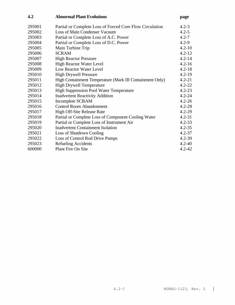
NUREG-1123, Rev. 2 |4.2-1
4.2 Abnormal Plant Evolutions page
295001 Partial or Complete Loss of Forced Core Flow Circulation 4.2-3295002 Loss of Main Condenser Vacuum 4.2-5295003 Partial or Complete Loss of A.C. Power 4.2-7295004 Partial or Complete Loss of D.C. Power 4.2-9295005 Main Turbine Trip 4.2-10295006 SCRAM 4.2-12295007 High Reactor Pressure 4.2-14295008 High Reactor Water Level 4.2-16295009 Low Reactor Water Level 4.2-18295010 High Drywell Pressure 4.2-19295011 High Containment Temperature (Mark III Containment Only) 4.2-21295012 High Drywell Temperature 4.2-22295013 High Suppression Pool Water Temperature 4.2-23295014 Inadvertent Reactivity Addition 4.2-24295015 Incomplete SCRAM 4.2-26295016 Control Room Abandonment 4.2-28295017 High Off-Site Release Rate 4.2-29295018 Partial or Complete Loss of Component Cooling Water 4.2-31295019 Partial or Complete Loss of Instrument Air 4.2-33295020 Inadvertent Containment Isolation 4.2-35295021 Loss of Shutdown Cooling 4.2-37295022 Loss of Control Rod Drive Pumps 4.2-39295023 Refueling Accidents 4.2-40600000 Plant Fire On Site 4.2-42

NUREG-1123, Rev. 2 |4.2-2
This page left blank

NUREG-1123, Rev. 2 |4.2-3
APE: 295001 Partial or Complete Loss of Forced Core Flow Circulation
IMPORTANCE K/A NO. KNOWLEDGE RO SRO
AK1. Knowledge of the operational implications of thefollowing concepts as they apply to PARTIAL ORCOMPLETE LOSS OF FORCED CORE FLOW CIRCULATION :(CFR: 41.8 to 41.10)
AK1.01 Natural circulation................................... 3.5 3.6AK1.02 Power/flow distribution............................... 3.3 3.5AK1.03 †Thermal limits........................................ 3.6 4.1AK1.04 †Limiting cycle oscillation: Plant-Specific........... 2.5 3.3
AK2. Knowledge of the interrelations between PARTIAL ORCOMPLETE LOSS OF FORCED CORE FLOW CIRCULATION and thefollowing:(CFR: 41.7 / 45.8)
AK2.01 Recirculation system.................................. 3.6 3.7AK2.02 Nuclear boiler instrumentation........................ 3.2 3.3AK2.03 Reactor water level................................... 3.6 3.7AK2.04 Reactor/turbine pressure regulating system: Plant-
Specific.............................................. 3.3 3.3AK2.05 LPCI loop select logic: Plant-Specific............... 3.2 3.6AK2.06 Reactor power......................................... 3.8 3.8AK2.07 Core flow indication.................................. 3.4 3.4AK2.08 Standby liquid control: BWR-1........................ 2.5* 2.8
AK3. Knowledge of the reasons for the following responsesas they apply to PARTIAL OR COMPLETE LOSS OF FORCEDCORE FLOW CIRCULATION :(CFR: 41.5 / 45.6)
AK3.01 Reactor water level response.......................... 3.4 3.6AK3.02 Reactor power response................................ 3.7 3.8AK3.03 Idle loop flow........................................ 2.8 2.9AK3.04 Reactor SCRAM......................................... 3.4 3.6AK3.05 Reduced loop operating requirements: Plant-Specific.. 3.2 3.6AK3.06 Core flow indication.................................. 2.9 3.0
ABILITY
AA1. Ability to operate and/or monitor the following as they apply to PARTIAL OR COMPLETELOSS OF FORCED CORE FLOW CIRCULATION :(CFR: 41.7 / 45.6)
AA1.01 Recirculation system.................................. 3.5 3.6AA1.02 RPS................................................... 3.3 3.3
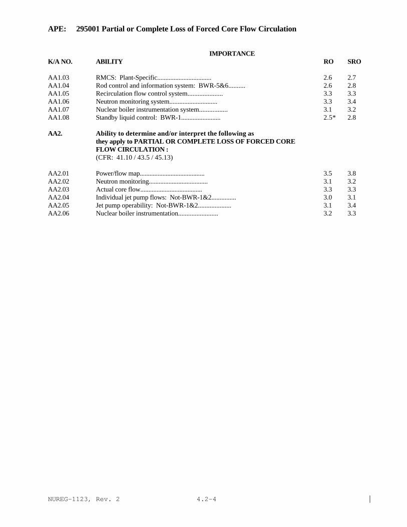
NUREG-1123, Rev. 2 |4.2-4
APE: 295001 Partial or Complete Loss of Forced Core Flow Circulation
IMPORTANCE K/A NO. ABILITY RO SRO
AA1.03 RMCS: Plant-Specific................................. 2.6 2.7AA1.04 Rod control and information system: BWR-5&6.......... 2.6 2.8AA1.05 Recirculation flow control system..................... 3.3 3.3AA1.06 Neutron monitoring system............................. 3.3 3.4AA1.07 Nuclear boiler instrumentation system................. 3.1 3.2AA1.08 Standby liquid control: BWR-1........................ 2.5* 2.8
AA2. Ability to determine and/or interpret the following asthey apply to PARTIAL OR COMPLETE LOSS OF FORCED COREFLOW CIRCULATION :(CFR: 41.10 / 43.5 / 45.13)
AA2.01 Power/flow map........................................ 3.5 3.8AA2.02 Neutron monitoring.................................... 3.1 3.2AA2.03 Actual core flow...................................... 3.3 3.3AA2.04 Individual jet pump flows: Not-BWR-1&2............... 3.0 3.1AA2.05 Jet pump operability: Not-BWR-1&2.................... 3.1 3.4AA2.06 Nuclear boiler instrumentation........................ 3.2 3.3

NUREG-1123, Rev. 2 |4.2-5
APE: 295002 Loss of Main Condenser Vacuum
IMPORTANCE K/A NO. KNOWLEDGE RO SRO
AK1. Knowledge of the operational implications of thefollowing concepts as they apply to LOSS OF MAINCONDENSER VACUUM :(CFR: 41.8 to 41.10)
AK1.01 Plant efficiency...................................... 2.1* 2.5AK1.02 Turbine efficiency.................................... 2.2* 2.5AK1.03 Loss of heat sink..................................... 3.6 3.8AK1.04 Increased offgas flow................................. 3.0 3.3
AK2. Knowledge of the interrelations between LOSS OF MAINCONDENSER VACUUM and the following:(CFR: 41.7 / 45.8)
AK2.01 RPS................................................... 3.5 3.5AK2.02 Main turbine.......................................... 3.1 3.2AK2.03 PCIS/NSSSS............................................ 3.5 3.6AK2.04 Reactor/turbine pressure regulating system............ 3.2 3.3AK2.05 Feedwater system...................................... 2.7 2.7AK2.06 Condensate system..................................... 2.6 2.7AK2.07 Offgas system......................................... 3.1 3.1AK2.08 Condenser circulating water system.................... 3.1 3.2AK2.09 Vacuum drag (low conductivity drain): Plant-Specific. 2.4 2.4AK2.10 Reactor recirculation system: Plant-Specific......... 2.4* 2.5AK2.11 Seal steam: Plant-Specific............................. 2.6 2.7
AK3. Knowledge of the reasons for the following responsesas they apply to LOSS OF MAIN CONDENSER VACUUM :(CFR: 41.5 / 45.6)
AK3.01 Reactor SCRAM: Plant-Specific........................ 3.7 3.8AK3.02 Turbine trip.......................................... 3.4 3.4AK3.03 Reactor feedpump turbine trip: Plant-Specific........ 3.3 3.3AK3.04 Bypass valve closure.................................. 3.4 3.6AK3.05 Main steam isolation valve: Plant-Specific........... 3.4 3.4AK3.06 Air ejector flow...................................... 2.9 2.9AK3.07 Decreased main generator output....................... 2.4 2.5AK3.08 Recirculation system run-backs: Plant-Specific....... 2.8 2.9AK3.09 Reactor power reduction............................... 3.2 3.2

NUREG-1123, Rev. 2 |4.2-6
APE: 295002 Loss of Main Condenser Vacuum
IMPORTANCE K/A NO. KNOWLEDGE RO SRO
ABILITY
AA1. Ability to operate and/or monitor the following as they apply to LOSS OF MAIN CONDENSER VACUUM :
(CFR: 41.7 / 45.6)
AA1.01 Condensate system 2.6 2.6AA1.02 Offgas system ........................................ . 2.9 2.9AA1.03 RPS. .................................................. 3.4 3.5AA1.04 PCIS/NSSSS ............................................ 3.3 3.4AA1.05 Main turbine .......................................... 3.2 3.2AA1.06 Reactor/turbine pressure regulating system ............ 3.0 3.1AA1.07 Condenser circulating water system .................... 3.1 2.9AA1.08 Recirculating flow control system ..................... 2.6 2.7AA1.09 Reactor manual control/rod control and information
system............................................. ... 2.4 2.4AA1.10 Feedwater system: Plant-Specific ..................... 2.7 2.7
AA2. Ability to determine and/or interpret the following asthey apply to LOSS OF MAIN CONDENSER VACUUM :(CFR: 41.10 / 43.5 / 45.13)
AA2.01 Condenser vacuum/absolute pressure.................... 2.9 3.1AA2.02 Reactor power: Plant-Specific........................ 3.2 3.3AA2.03 Generator output...................................... 2.3 2.4AA2.04 Offgas system flow.................................... 2.8 2.9
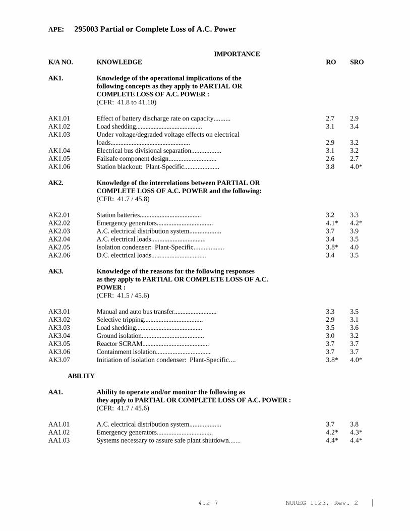
NUREG-1123, Rev. 2 |4.2-7
APE: 295003 Partial or Complete Loss of A.C. Power
IMPORTANCE K/A NO. KNOWLEDGE RO SRO
AK1. Knowledge of the operational implications of thefollowing concepts as they apply to PARTIAL ORCOMPLETE LOSS OF A.C. POWER :(CFR: 41.8 to 41.10)
AK1.01 Effect of battery discharge rate on capacity.......... 2.7 2.9AK1.02 Load shedding......................................... 3.1 3.4AK1.03 Under voltage/degraded voltage effects on electrical
loads................................................. 2.9 3.2AK1.04 Electrical bus divisional separation.................. 3.1 3.2AK1.05 Failsafe component design............................. 2.6 2.7AK1.06 Station blackout: Plant-Specific..................... 3.8 4.0*
AK2. Knowledge of the interrelations between PARTIAL ORCOMPLETE LOSS OF A.C. POWER and the following:(CFR: 41.7 / 45.8)
AK2.01 Station batteries..................................... 3.2 3.3AK2.02 Emergency generators.................................. 4.1* 4.2*AK2.03 A.C. electrical distribution system................... 3.7 3.9AK2.04 A.C. electrical loads................................. 3.4 3.5AK2.05 Isolation condenser: Plant-Specific.................. 3.8* 4.0AK2.06 D.C. electrical loads................................. 3.4 3.5
AK3. Knowledge of the reasons for the following responsesas they apply to PARTIAL OR COMPLETE LOSS OF A.C.POWER :(CFR: 41.5 / 45.6)
AK3.01 Manual and auto bus transfer.......................... 3.3 3.5AK3.02 Selective tripping.................................... 2.9 3.1AK3.03 Load shedding......................................... 3.5 3.6AK3.04 Ground isolation...................................... 3.0 3.2AK3.05 Reactor SCRAM......................................... 3.7 3.7AK3.06 Containment isolation................................. 3.7 3.7AK3.07 Initiation of isolation condenser: Plant-Specific.... 3.8* 4.0*
ABILITY
AA1. Ability to operate and/or monitor the following as they apply to PARTIAL OR COMPLETE LOSS OF A.C. POWER :
(CFR: 41.7 / 45.6)
AA1.01 A.C. electrical distribution system................... 3.7 3.8AA1.02 Emergency generators.................................. 4.2* 4.3*AA1.03 Systems necessary to assure safe plant shutdown....... 4.4* 4.4*

NUREG-1123, Rev. 2 |4.2-8
APE: 295003 Partial or Complete Loss of A.C. Power
IMPORTANCE K/A NO. ABILITY RO SRO
AA1.04 D.C. electrical distribution system................... 3.6 3.7
AA2. Ability to determine and/or interpret the following asthey apply to PARTIAL OR COMPLETE LOSS OF A.C. POWER :(CFR: 41.10 / 43.5 / 45.13)
AA2.01 Cause of partial or complete loss of A.C. power....... 3.4 3.7AA2.02 Reactor power / pressure / and level.................... 4.2* 4.3*AA2.03 Battery status: Plant-Specific....................... 3.2 3.5AA2.04 System lineups........................................ 3.5 3.7AA2.05 Whether a partial or complete loss of A.C. power has
occurred.............................................. 3.9* 4.2*

NUREG-1123, Rev. 2 |4.2-9
APE: 295004 Partial or Complete Loss of D.C. Power
IMPORTANCE K/A NO. KNOWLEDGE RO SRO
AK1. Knowledge of the operational implications of thefollowing concepts as they apply to PARTIAL ORCOMPLETE LOSS OF D.C. POWER :(CFR: 41.8 to 41.10)
AK1.01 †Automatic load shedding: Plant-Specific.............. 2.9 3.2AK1.02 Redundant D.C. power supplies: Plant-Specific........ 3.2 3.4AK1.03 Electrical bus divisional separation.................. 2.9 2.9AK1.04 Effect of battery discharge rate on capacity.......... 2.8 2.9AK1.05 Loss of breaker protection............................ 3.3 3.4AK1.06 Prevention of inadvertent system(s) actuation upon
restoration of D.C. power............................. 3.3 3.6
AK2. Knowledge of the interrelations between PARTIAL ORCOMPLETE LOSS OF D.C. POWER and the following:(CFR: 41.7 / 45.8)
AK2.01 Battery charger....................................... 3.1 3.1AK2.02 Batteries............................................. 3.0 3.1AK2.03 D.C. bus loads........................................ 3.3 3.3
AK3. Knowledge of the reasons for the following responsesas they apply to PARTIAL OR COMPLETE LOSS OF D.C.POWER :(CFR: 41.5 / 45.6)
AK3.01 †Load shedding: Plant-Specific........................ 2.6 3.1AK3.02 Ground isolation/fault determination.................. 2.9 3.3AK3.03 Reactor SCRAM: Plant-Specific........................ 3.1 3.5
ABILITY
AA1. Ability to operate and/or monitor the following as they apply to PARTIAL OR COMPLETE LOSS OF D.C. POWER :
(CFR: 41.7 / 45.6)
AA1.01 D.C. electrical distribution systems.................. 3.3 3.4AA1.02 Systems necessary to assure safe plant shutdown....... 3.8 4.1AA1.03 A.C. electrical distribution.......................... 3.4 3.6
AA2. Ability to determine and/or interpret the following asthey apply to PARTIAL OR COMPLETE LOSS OF D.C. POWER :(CFR: 41.10 / 43.5 / 45.13)
AA2.01 Cause of partial or complete loss of D.C. power....... 3.2 3.6AA2.02 Extent of partial or complete loss of D.C. power...... 3.5 3.9AA2.03 Battery voltage....................................... 2.8 2.9AA2.04 System lineups........................................ 3.2 3.3
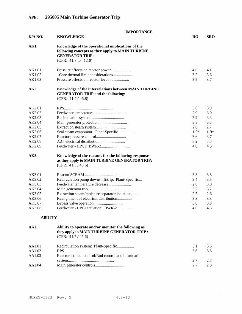
NUREG-1123, Rev. 2 |4.2-10
APE: 295005 Main Turbine Generator Trip
IMPORTANCE K/A NO. KNOWLEDGE RO SRO
AK1. Knowledge of the operational implications of thefollowing concepts as they apply to MAIN TURBINEGENERATOR TRIP :(CFR: 41.8 to 41.10)
AK1.01 Pressure effects on reactor power.................... 4.0 4.1AK1.02 †Core thermal limit considerations.................... 3.2 3.6AK1.03 Pressure effects on reactor level.................... 3.5 3.7
AK2. Knowledge of the interrelations between MAIN TURBINEGENERATOR TRIP and the following:(CFR: 41.7 / 45.8)
AK2.01 RPS................................................... 3.8 3.9AK2.02 Feedwater temperature................................. 2.9 3.0AK2.03 Recirculation system.................................. 3.2 3.3AK2.04 Main generator protection............................. 3.3 3.3AK2.05 Extraction steam system............................... 2.6 2.7AK2.06 Seal steam evaporator: Plant-Specific................ 1.9* 1.9*AK2.07 Reactor pressure control.............................. 3.6 3.7AK2.08 A.C. electrical distribution.:........................ 3.2 3.3AK2.09 Feedwater - HPCI: BWR-2.............................. 4.0 4.3
AK3. Knowledge of the reasons for the following responsesas they apply to MAIN TURBINE GENERATOR TRIP:(CFR: 41.5 / 45.6)
AK3.01 Reactor SCRAM........................................ 3.8 3.8AK3.02 Recirculation pump downshift/trip: Plant-Specific... 3.4 3.5AK3.03 Feedwater temperature decrease....................... 2.8 3.0AK3.04 Main generator trip.................................. 3.2 3.2AK3.05 Extraction steam/moisture separator isolations....... 2.5 2.6AK3.06 Realignment of electrical distribution............... 3.3 3.3AK3.07 Bypass valve operation............................... 3.8 3.8AK3.08 Feedwater - HPCI actuation: BWR-2................... 4.0 4.3
ABILITY
AA1. Ability to operate and/or monitor the following as they apply to MAIN TURBINE GENERATOR TRIP :
(CFR: 41.7 / 45.6)
AA1.01 Recirculation system: Plant-Specific................. 3.1 3.3AA1.02 RPS................................................... 3.6 3.6AA1.03 Reactor manual control/Rod control and information
system................................................ 2.7 2.8AA1.04 Main generator controls............................... 2.7 2.8

NUREG-1123, Rev. 2 |4.2-11
APE: 295005 Main Turbine Generator Trip
IMPORTANCE K/A NO. KNOWLEDGE RO SRO
AA1.05 Reactor/turbine pressure regulating system............ 3.6 3.6AA1.06 Condenser vacuum breaker.............................. 2.4 2.6AA1.07 A.C. electrical distribution.......................... 3.3 3.3
AA2. Ability to determine and/or interpret the following asthey apply to MAIN TURBINE GENERATOR TRIP :(CFR: 41.10 / 43.5 / 45.13)
AA2.01 Turbine speed......................................... 2.6 2.7AA2.02 Turbine vibration..................................... 2.4 2.7AA2.03 Turbine valve position................................ 3.1 3.1AA2.04 Reactor pressure...................................... 3.7 3.8AA2.05 Reactor power......................................... 3.8 3.9AA2.06 Feedwater temperature................................. 2.6 2.7AA2.07 Reactor water level................................... 3.5 3.6AA2.08 Electrical distribution status........................ 3.2 3.3

NUREG-1123, Rev. 2 |4.2-12
APE: 295006 SCRAM
IMPORTANCE K/A NO. KNOWLEDGE RO SRO
AK1. Knowledge of the operational implications of thefollowing concepts as they apply to SCRAM :(CFR: 41.8 to 41.10)
AK1.01 Decay heat generation and removal..................... 3.7 3.9AK1.02 Shutdown margin....................................... 3.4 3.7AK1.03 Reactivity control.................................... 3.7 4.0
AK2. Knowledge of the interrelations between SCRAM and thefollowing:(CFR: 41.7 / 45.8)
AK2.01 RPS................................................... 4.3* 4.4*AK2.02 Reactor water level control system.................... 3.8 3.8AK2.03 CRD hydraulic system.................................. 3.7 3.8AK2.04 Turbine trip logic: Plant-Specific.................... 3.6 3.7AK2.05 CRD mechanism......................................... 3.1 3.3AK2.06 Reactor power......................................... 4.2* 4.3*AK2.07 Reactor pressure control.............................. 4.0 4.1
AK3. Knowledge of the reasons for the following responsesas they apply to SCRAM :(CFR: 41.5 / 45.6)
AK3.01 Reactor water level response.......................... 3.8 3.9AK3.02 Reactor power response................................ 4.1* 4.2*AK3.03 Reactor pressure response............................. 3.8 3.9*AK3.04 Reactor water level setpoint setdown: Plant-Specific.. 3.1 3.3AK3.05 Direct turbine generator trip: Plant-Specific......... 3.8 4.0AK3.06 Recirculation pump speed reduction: Plant-Specific.... 3.2 3.3
ABILITY
AA1. Ability to operate and/or monitor the following as they apply to SCRAM :
(CFR: 41.7 / 45.6)
AA1.01 RPS................................................... 4.2* 4.2*AA1.02 Reactor water level control system.................... 3.9 3.8AA1.03 Reactor/turbine pressure regulating system............ 3.7 3.7AA1.04 Recirculation system.................................. 3.1 3.2AA1.05 Neutron monitoring system............................. 4.2* 4.2*AA1.06 CRD hydraulic system.................................. 3.5 3.6AA1.07 Control rod position.................................. 4.1 4.1

NUREG-1123, Rev. 2 |4.2-13
APE: 295006 SCRAM
IMPORTANCE K/A NO. ABILITY RO SRO
AA2. Ability to determine and/or interpret the following as they apply to SCRAM :(CFR: 41.10 / 43.5 / 45.13)
AA2.01 Reactor power......................................... 4.5* 4.6*AA2.02 Control rod position.................................. 4.3* 4.4*AA2.03 Reactor water level................................... 4.0 4.2*AA2.04 Reactor pressure...................................... 4.1 4.1*AA2.05 Whether a reactor SCRAM has occurred.................. 4.6* 4.6*AA2.06 Cause of reactor SCRAM................................ 3.5 3.8

NUREG-1123, Rev. 2 |4.2-14
APE: 295007 High Reactor Pressure
IMPORTANCE K/A NO. KNOWLEDGE RO SRO
AK1. Knowledge of the operational implications of thefollowing concepts as they apply to HIGH REACTORPRESSURE :(CFR: 41.8 to 41.10)
AK1.01 Pump shutoff head..................................... 2.9 3.2AK1.02 Decay heat generation................................. 3.1 3.4AK1.03 Pressure effects on reactor power..................... 3.8 3.9AK1.04 Turbine load.......................................... 2.7 2.8
AK2. Knowledge of the interrelations between HIGH REACTORPRESSURE and the following:(CFR: 41.7 / 45.8)
AK2.01 Reactor/turbine pressure regulating system............ 3.5 3.7AK2.02 Reactor power......................................... 3.8 3.8AK2.03 RHR/LPCI: Plant-Specific............................. 3.1 3.2AK2.04 LPCS.................................................. 3.2 3.3AK2.05 Shutdown cooling: Plant-Specific..................... 2.9 3.1AK2.06 PCIS/NSSSS: Plant-Specific........................... 3.5 3.7
AK3. Knowledge of the reasons for the following responsesas they apply to HIGH REACTOR PRESSURE :(CFR: 41.5 / 45.6)
AK3.01 Isolation condenser operation: Plant-Specific........ 4.0 4.2AK3.02 HPCI operation: Plant-Specific....................... 3.7 3.8*AK3.03 RCIC operation: Plant-Specific....................... 3.4 3.5AK3.04 Safety/relief valve operation: Plant-Specific........ 4.0 4.1*AK3.05 Low pressure system isolation......................... 3.0 3.2AK3.06 Reactor/turbine pressure regulating system operation.. 3.7 3.8
ABILITY
AA1. Ability to operate and/or monitor the following as they apply to HIGH REACTOR PRESSURE :
(CFR: 41.7 / 45.6)
AA1.01 Isolation condenser: Plant-Specific.................. 4.0 4.2AA1.02 HPCI: Plant-Specific................................. 3.5 3.7*AA1.03 RCIC: Plant-Specific................................. 3.4 3.5AA1.04 Safety/relief valve operation: Plant-Specific........ 3.9 4.1*AA1.05 Reactor/turbine pressure regulating system............ 3.7 3.8

NUREG-1123, Rev. 2 |4.2-15
APE: 295007 High Reactor Pressure
IMPORTANCE K/A NO. KNOWLEDGE RO SRO
AA2. Ability to determine and/or interpret the following asthey apply to HIGH REACTOR PRESSURE :(CFR: 41.10 / 43.5 / 45.13)
AA2.01 Reactor pressure...................................... 4.1* 4.1*AA2.02 Reactor power......................................... 4.1* 4.1*AA2.03 Reactor water level................................... 3.7 3.7

NUREG-1123, Rev. 2 |4.2-16
APE: 295008 High Reactor Water Level
IMPORTANCE K/A NO. KNOWLEDGE RO SRO
AK1. Knowledge of the operational implications of thefollowing concepts as they apply to HIGH REACTOR WATER LEVEL :(CFR: 41.8 to 41.10)
AK1.01 Moisture carryover.................................... 3.0 3.2AK1.02 Component erosion/damage.............................. 2.8 2.8AK1.03 Feed flow/steam flow mismatch......................... 3.2 3.2AK1.04 Containment integrity: Alis-Chalmers................. 4.0 4.3*
AK2. Knowledge of the interrelations between HIGH REACTORWATER LEVEL and the following:(CFR: 41.7 / 45.8)
AK2.01 RPS: Plant-Specific.................................. 3.7 3.8AK2.02 Reactor feedwater system.............................. 3.6 3.8AK2.03 Reactor water level control........................... 3.6 3.7AK2.04 PCIS/NSSSS: Plant-Specific............................ 3.1 3.3AK2.05 HPCI: Plant-Specific................................. 3.8 3.9AK2.06 RCIC: Plant-Specific................................. 3.4 3.6AK2.07 HPCS: Plant-Specific................................. 2.9 3.0AK2.08 Main turbine: Plant-Specific......................... 3.4 3.5AK2.09 Reactor water cleanup system (ability to drain):
Plant-Specific........................................ 3.1 3.1AK2.10 RHR (ability to drain): Plant-Specific............... 2.7 2.8AK2.11 Main steam............................................ 3.1 3.3
AK3. Knowledge of the reasons for the following responsesas they apply to HIGH REACTOR WATER LEVEL :(CFR: 41.5 / 45.6)
AK3.01 Main turbine trip..................................... 3.4 3.5AK3.02 Reactor SCRAM: Plant-Specific........................ 3.6* 3.9*AK3.03 PCIS/NSSSS initiation: Plant-Specific................ 2.9 3.1AK3.04 Reactor feed pump trip: Plant-Specific............... 3.3 3.5AK3.05 HPCI turbine trip: Plant-Specific.................... 3.5 3.6AK3.06 RCIC turbine trip: Plant-Specific.................... 3.4 3.5AK3.07 HPCS isolation: Plant-Specific....................... 3.2 3.3AK3.08 RCIC steam supply valve closure: Plant-Specific...... 3.4 3.5AK3.09 HPCS injection valve closure: Plant-Specific......... 3.3 3.4

NUREG-1123, Rev. 2 |4.2-17
IMPORTANCE K/A NO. ABILITY RO SRO
AA1. Ability to operate and/or monitor the following as they apply to HIGH REACTOR WATER LEVEL :
(CFR: 41.7 / 45.6)
AA1.01 Reactor water level control: Plant-Specific.......... 3.7 3.7AA1.02 Reactor water cleanup (ability to drain): Plant-
Specific.............................................. 3.3 3.3AA1.03 Main steam system: Plant-Specific.................... 3.1 3.1AA1.04 HPCI: Plant-Specific................................. 3.5 3.5AA1.05 RCIC: Plant-Specific................................. 3.3 3.3AA1.06 HPCS: Plant-Specific................................. 2.8 2.8AA1.07 Main turbine: Plant-Specific......................... 3.4 3.4AA1.08 Feedwater system...................................... 3.5 3.5AA1.09 Ability to drain: Plant-Specific..................... 3.3 3.3
AA2. Ability to determine and/or interpret the following asthey apply to HIGH REACTOR WATER LEVEL :(CFR: 41.10 / 43.5 / 45.13)
AA2.01 Reactor water level................................... 3.9 3.9AA2.02 Steam flow/feedflow mismatch.......................... 3.4 3.4AA2.03 Reactor water cleanup blowdown flow................... 2.9 3.0AA2.04 Heatup rate: Plant-Specific......................... 3.1 3.3AA2.05 Swell................................................. 2.9 3.1

NUREG-1123, Rev. 2 |4.2-18
APE: 295009 Low Reactor Water Level
IMPORTANCE K/A NO. KNOWLEDGE RO SRO
AK1. Knowledge of the operational implications of thefollowing concepts as they apply to LOW REACTOR WATERLEVEL :(CFR: 41.8 to 41.10)
AK1.01 Steam carryunder...................................... 2.7 2.9AK1.02 Recirculation pump net positive suction head: Plant-
Specific.............................................. 3.0 3.1AK1.03 Jet pump net positive suction head: Not-BWR-1&2...... 2.7 2.7AK1.04 Jet pump efficiency: Not-BWR-1&2..................... 2.4 2.4AK1.05 Natural circulation................................... 3.3 3.4
AK2. Knowledge of the interrelations between LOW REACTORWATER LEVEL and the following:(CFR: 41.7 / 45.8)
AK2.01 Reactor water level indication........................ 3.9 4.0AK2.02 Reactor water level control........................... 3.9 3.9AK2.03 Recirculation system.................................. 3.1 3.2AK2.04 Reactor water cleanup................................. 2.6 2.6
AK3. Knowledge of the reasons for the following responsesas they apply to LOW REACTOR WATER LEVEL :(CFR: 41.5 / 45.6)
AK3.01 Recirculation pump run back: Plant-Specific.......... 3.2 3.3AK3.02 Reactor feedpump runout flow control: Plant-Specific. 2.7 2.8
ABILITY
AA1. Ability to operate and/or monitor the following asthey apply to LOW REACTOR WATER LEVEL :(CFR: 41.7 / 45.6)
AA1.01 Reactor feedwater..................................... 3.9 3.9AA1.02 Reactor water level control........................... 4.0 4.0AA1.03 Recirculation system: Plant-Specific................. 3.0 3.1AA1.04 Reactor water cleanup................................. 2.7 2.7
AA2. Ability to determine and/or interpret the following asthey apply to LOW REACTOR WATER LEVEL :(CFR: 41.10 / 43.5 / 45.13)
AA2.01 Reactor water level................................... 4.2 4.2AA2.02 Steam flow/feed flow mismatch......................... 3.6 3.7AA2.03 Reactor water cleanup blowdown rate................... 2.9 2.9

NUREG-1123, Rev. 2 |4.2-19
APE: 295010 High Drywell Pressure
IMPORTANCE K/A NO. KNOWLEDGE RO SRO
AK1. Knowledge of the operational implications of thefollowing concepts as they apply to HIGH DRYWELLPRESSURE :(CFR: 41.8 to 41.10)
AK1.01 Downcomer submergence: Mark-I&II..................... 3.0 3.4AK1.02 Submergence vent control: Mark-III................... 2.8 3.1*AK1.03 Temperature increases................................. 3.2 3.4
AK2. Knowledge of the interrelations between HIGH DRYWELLPRESSURE and the following:(CFR: 41.7 / 45.8)
AK2.01 Suppression pool level................................ 3.2 3.3AK2.02 Drywell/suppression chamber differential pressure:
Mark-I&II............................................. 3.3 3.5AK2.03 Drywell/containment differential pressure: Mark-III.. 3.0 3.1AK2.04 Nitrogen makeup system: Plant-Specific............... 2.6 2.8AK2.05 Drywell cooling and ventilation....................... 3.7 3.8
AK3. Knowledge of the reasons for the following responsesas they apply to HIGH DRYWELL PRESSURE :(CFR: 41.5 / 45.6)
AK3.01 Drywell venting....................................... 3.8 4.0*AK3.02 Increased drywell cooling............................. 3.4 3.4AK3.03 Radiation level monitoring............................ 3.2 3.5AK3.04 Leak investigation.................................... 3.5 3.8AK3.05 Temperature monitoring................................ 3.5 3.4AK3.06 Termination of drywell inerting: Plant-Specific...... 2.4* 2.8
ABILITY
AA1. Ability to operate and/or monitor the following as they apply to HIGH DRYWELL PRESSURE :
(CFR: 41.7 / 45.6)
AA1.01 Drywell ventilation/cooling........................... 3.4 3.5AA1.02 Drywell floor and equipment drain sumps............... 3.6 3.6AA1.03 Nitrogen makeup: Plant-Specific...................... 2.6 2.6AA1.04 Drywell sampling system............................... 3.1 3.0AA1.05 Drywell/suppression vent and purge.................... 3.1 3.4AA1.06 Leakage detection systems............................. 3.3 3.5AA1.07 Containment (drywell) atmosphere control.............. 3.2 3.4

NUREG-1123, Rev. 2 |4.2-20
APE: 295010 High Drywell Pressure
IMPORTANCE K/A NO. ABILITY RO SRO
AA2. Ability to determine and/or interpret the following asthey apply to HIGH DRYWELL PRESSURE :(CFR: 41.10 / 43.5 / 45.13)
AA2.01 †Leak rates............................................ 3.4 3.8AA2.02 Drywell pressure..................................... 3.8 3.9AA2.03 Drywell radiation levels............................. 3.3 3.6AA2.04 Drywell humidity: Plant-Specific..................... 2.8 3.0AA2.05 Drywell air cooler drain flow: BWR-6................. 3.3 3.3|AA2.06 Drywell temperature.................................. 3.6 3.6|
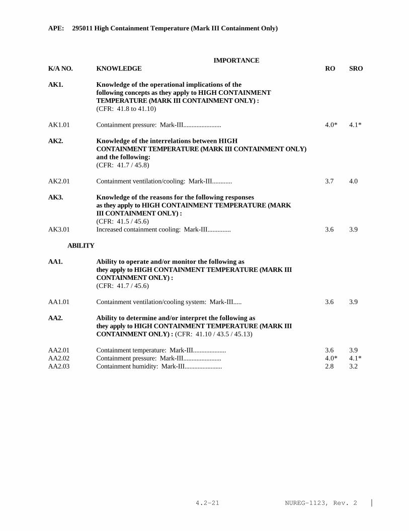
NUREG-1123, Rev. 2 |4.2-21
APE: 295011 High Containment Temperature (Mark III Containment Only)
IMPORTANCE K/A NO. KNOWLEDGE RO SRO
AK1. Knowledge of the operational implications of the following concepts as they apply to HIGH CONTAINMENT TEMPERATURE (MARK III CONTAINMENT ONLY) :(CFR: 41.8 to 41.10)
AK1.01 Containment pressure: Mark-III....................... 4.0* 4.1*
AK2. Knowledge of the interrelations between HIGHCONTAINMENT TEMPERATURE (MARK III CONTAINMENT ONLY)and the following:(CFR: 41.7 / 45.8)
AK2.01 Containment ventilation/cooling: Mark-III............ 3.7 4.0
AK3. Knowledge of the reasons for the following responsesas they apply to HIGH CONTAINMENT TEMPERATURE (MARKIII CONTAINMENT ONLY) :(CFR: 41.5 / 45.6)
AK3.01 Increased containment cooling: Mark-III.............. 3.6 3.9
ABILITY
AA1. Ability to operate and/or monitor the following asthey apply to HIGH CONTAINMENT TEMPERATURE (MARK IIICONTAINMENT ONLY) :(CFR: 41.7 / 45.6)
AA1.01 Containment ventilation/cooling system: Mark-III..... 3.6 3.9
AA2. Ability to determine and/or interpret the following asthey apply to HIGH CONTAINMENT TEMPERATURE (MARK IIICONTAINMENT ONLY) : (CFR: 41.10 / 43.5 / 45.13)
AA2.01 Containment temperature: Mark-III.................... 3.6 3.9AA2.02 Containment pressure: Mark-III....................... 4.0* 4.1*AA2.03 Containment humidity: Mark-III....................... 2.8 3.2

NUREG-1123, Rev. 2 |4.2-22
APE: 295012 High Drywell Temperature
IMPORTANCE K/A NO. KNOWLEDGE RO SRO
AK1. Knowledge of the operational implications of the following concepts as they apply to HIGH DRYWELL TEMPERATURE :(CFR: 41.8 to 41.10)
AK1.01 Pressure/temperature relationship..................... 3.3 3.5AK1.02 Reactor power level control........................... 3.1 3.2
AK2. Knowledge of the interrelations between HIGH DRYWELLTEMPERATURE and the following:(CFR: 41.7 / 45.8)
AK2.01 Drywell ventilation................................... 3.4 3.5AK2.02 Drywell cooling....................................... 3.6 3.7
AK3. Knowledge of the reasons for the following responsesas they apply to HIGH DRYWELL TEMPERATURE :(CFR: 41.5 / 45.6)
AK3.01 Increased drywell cooling............................. 3.5 3.6
ABILITY
AA1. Ability to operate and/or monitor the following asthey apply to HIGH DRYWELL TEMPERATURE :(CFR: 41.7 / 45.6)
AA1.01 Drywell ventilation system............................ 3.5 3.6AA1.02 Drywell cooling system................................ 3.8 3.8
AA2. Ability to determine and/or interpret the following asthey apply to HIGH DRYWELL TEMPERATURE :(CFR: 41.10 / 43.5 / 45.13)
AA2.01 Drywell temperature................................... 3.8 3.9AA2.02 Drywell pressure...................................... 3.9 4.1AA2.03 Drywell humidity: Plant-Specific..................... 2.8 3.1

NUREG-1123, Rev. 2 |4.2-23
APE: 295013 High Suppression Pool Temperature
IMPORTANCE K/A NO. KNOWLEDGE RO SRO
AK1. Knowledge of the operational implications of thefollowing concepts as they apply to HIGH SUPPRESSIONPOOL TEMPERATURE :(CFR: 41.8 to 41.10)
AK1.01 Pool stratification................................... 2.5 2.6AK1.02 Ambient temperature effects........................... 2.4 2.5AK1.03 Localized heating..................................... 3.0 3.3AK1.04 Complete condensation................................. 2.9 3.2
AK2. Knowledge of the interrelations between HIGHSUPPRESSION POOL TEMPERATURE and the following:(CFR: 41.7 / 45.8)
AK2.01 Suppression pool cooling.............................. 3.6 3.7
AK3. Knowledge of the reasons for the following responsesas they apply to HIGH SUPPRESSION POOL TEMPERATURE :(CFR: 41.5 / 45.6)
AK3.01 Suppression pool cooling operation.................... 3.6 3.8AK3.02 Limiting heat additions............................... 3.6 3.8
ABILITY
AA1. Ability to operate and/or monitor the following as they apply to HIGH SUPPRESSION POOL TEMPERATURE :
(CFR: 41.7 / 45.6)
AA1.01 Suppression pool cooling.............................. 3.9 3.9AA1.02 Systems that add heat to the suppression pool......... 3.9 3.9
AA2. Ability to determine and/or interpret the following asthey apply to HIGH SUPPRESSION POOL TEMPERATURE :(CFR: 41.10 / 43.5 / 45.13)
AA2.01 Suppression pool temperature.......................... 3.8 4.0AA2.02 Localized heating/stratification...................... 3.2 3.5
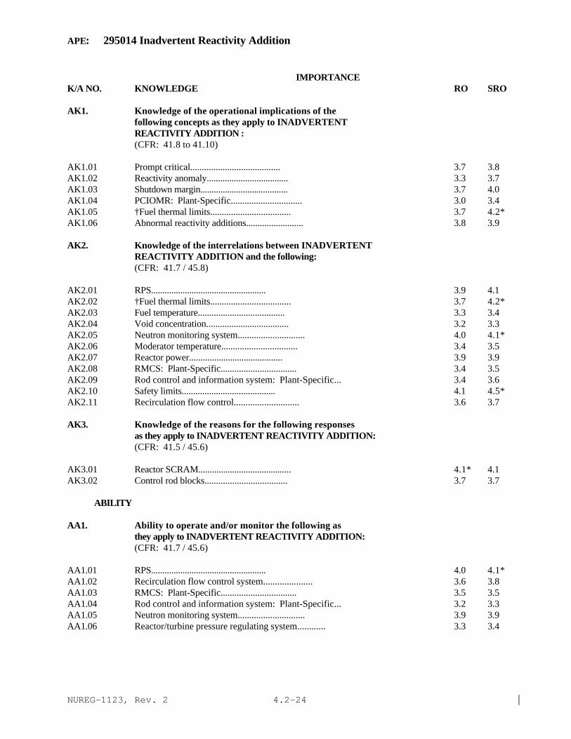
NUREG-1123, Rev. 2 |4.2-24
APE: 295014 Inadvertent Reactivity Addition
IMPORTANCE K/A NO. KNOWLEDGE RO SRO
AK1. Knowledge of the operational implications of thefollowing concepts as they apply to INADVERTENTREACTIVITY ADDITION :(CFR: 41.8 to 41.10)
AK1.01 Prompt critical....................................... 3.7 3.8AK1.02 Reactivity anomaly.................................... 3.3 3.7AK1.03 Shutdown margin....................................... 3.7 4.0AK1.04 PCIOMR: Plant-Specific............................... 3.0 3.4AK1.05 †Fuel thermal limits................................... 3.7 4.2*AK1.06 Abnormal reactivity additions......................... 3.8 3.9
AK2. Knowledge of the interrelations between INADVERTENTREACTIVITY ADDITION and the following:(CFR: 41.7 / 45.8)
AK2.01 RPS................................................... 3.9 4.1AK2.02 †Fuel thermal limits................................... 3.7 4.2*AK2.03 Fuel temperature...................................... 3.3 3.4AK2.04 Void concentration.................................... 3.2 3.3AK2.05 Neutron monitoring system............................. 4.0 4.1*AK2.06 Moderator temperature................................. 3.4 3.5AK2.07 Reactor power......................................... 3.9 3.9AK2.08 RMCS: Plant-Specific................................. 3.4 3.5AK2.09 Rod control and information system: Plant-Specific... 3.4 3.6AK2.10 Safety limits......................................... 4.1 4.5*AK2.11 Recirculation flow control............................ 3.6 3.7
AK3. Knowledge of the reasons for the following responsesas they apply to INADVERTENT REACTIVITY ADDITION:(CFR: 41.5 / 45.6)
AK3.01 Reactor SCRAM......................................... 4.1* 4.1AK3.02 Control rod blocks.................................... 3.7 3.7
ABILITY
AA1. Ability to operate and/or monitor the following as they apply to INADVERTENT REACTIVITY ADDITION:
(CFR: 41.7 / 45.6)
AA1.01 RPS................................................... 4.0 4.1*AA1.02 Recirculation flow control system..................... 3.6 3.8AA1.03 RMCS: Plant-Specific................................. 3.5 3.5AA1.04 Rod control and information system: Plant-Specific... 3.2 3.3AA1.05 Neutron monitoring system............................. 3.9 3.9AA1.06 Reactor/turbine pressure regulating system............ 3.3 3.4

NUREG-1123, Rev. 2 |4.2-25
APE: 295014 Inadvertent Reactivity Addition
IMPORTANCE K/A NO. KNOWLEDGE RO SRO
AA1.07 Cold water injection.................................. 4.0 4.1
AA2. Ability to determine and/or interpret the following asthey apply to INADVERTENT REACTIVITY ADDITION :(CFR: 41.10 / 43.5 / 45.13)
AA2.01 Reactor power......................................... 4.1* 4.2*AA2.02 Reactor period........................................ 3.9 3.9AA2.03 Cause of reactivity addition.......................... 4.0 4.3*AA2.04 †Violation of fuel thermal limits...................... 4.1 4.4*AA2.05 †Violation of safety limits 4.2* 4.6* |

NUREG-1123, Rev. 2 |4.2-26
APE: 295015 Incomplete SCRAM
IMPORTANCE K/A NO. KNOWLEDGE RO SRO
AK1. Knowledge of the operational implications of thefollowing concepts as they apply to INCOMPLETE SCRAM :(CFR: 41.8 to 41.10)
AK1.01 Shutdown margin....................................... 3.6* 3.9*AK1.02 Cooldown effects on reactor power..................... 3.9 4.1AK1.03 Reactivity effects.................................... 3.8 3.9AK1.04 Reactor pressure: Plant-Specific..................... 3.8 3.8
AK2. Knowledge of the interrelations between INCOMPLETESCRAM and the following:(CFR: 41.7 / 45.8)
AK2.01 CRD hydraulics........................................ 3.8 3.9AK2.02 RMCS: Plant-Specific................................. 3.6 3.7AK2.03 Rod control and information system: Plant-Specific... 3.2 3.6AK2.04 RPS................................................... 4.0 4.1AK2.05 Rod worth minimizer: Plant-Specific.................. 2.6 2.8AK2.06 RSCS: Plant-Specific................................. 2.6 2.8AK2.07 CRD mechanism......................................... 3.3 3.4AK2.08 Neutron monitoring system............................. 3.6 3.7AK2.09 RPIS.................................................. 3.5 3.6AK2.10 SPDS/ERIS/CRIDS/GDS: Plant-Specific.................. 2.8 3.0AK2.11 Instrument air........................................ 3.5 3.7
AK3. Knowledge of the reasons for the following responsesas they apply to INCOMPLETE SCRAM :(CFR: 41.5 / 45.6)
AK3.01 Bypassing rod insertion blocks........................ 3.4 3.7
ABILITY
AA1. Ability to operate and/or monitor the following as they apply to INCOMPLETE SCRAM :
(CFR: 41.7 / 45.6)
AA1.01 CRD hydraulics........................................ 3.8 3.9AA1.02 RPS................................................... 4.0 4.2*AA1.03 RMCS: Plant-Specific................................. 3.6 3.8AA1.04 Rod control and information system: Plant-Specific... 3.4 3.7AA1.05 Rod worth minimizer: Plant-Specific.................. 2.5* 2.8*AA1.06 RSCS: Plant-Specific................................. 2.7 2.9

NUREG-1123, Rev. 2 |4.2-27
APE: 295015 Incomplete SCRAM
IMPORTANCE K/A NO. ABILITY RO SRO
AA1.07 Neutron monitoring system............................. 3.6 3.7AA1.08 Process computer/SPDS/ERIS/CRIDS/GDS: Plant-Specific. 2.7 2.9
AA2. Ability to determine and/or interpret the following asthey apply to INCOMPLETE SCRAM :(CFR: 41.10 / 43.5 / 45.13)
AA2.01 Reactor power......................................... 4.1* 4.3*AA2.02 Control rod position.................................. 4.1* 4.2*
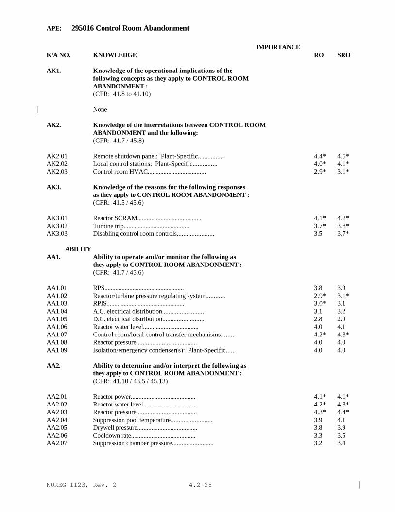
NUREG-1123, Rev. 2 |4.2-28
APE: 295016 Control Room Abandonment
IMPORTANCE K/A NO. KNOWLEDGE RO SRO
AK1. Knowledge of the operational implications of thefollowing concepts as they apply to CONTROL ROOMABANDONMENT :(CFR: 41.8 to 41.10)
None|
AK2. Knowledge of the interrelations between CONTROL ROOMABANDONMENT and the following:(CFR: 41.7 / 45.8)
AK2.01 Remote shutdown panel: Plant-Specific................ 4.4* 4.5*AK2.02 Local control stations: Plant-Specific............... 4.0* 4.1*AK2.03 Control room HVAC..................................... 2.9* 3.1*
AK3. Knowledge of the reasons for the following responsesas they apply to CONTROL ROOM ABANDONMENT :(CFR: 41.5 / 45.6)
AK3.01 Reactor SCRAM......................................... 4.1* 4.2*AK3.02 Turbine trip.......................................... 3.7* 3.8*AK3.03 Disabling control room controls....................... 3.5 3.7*
ABILITYAA1. Ability to operate and/or monitor the following as they apply to CONTROL ROOM ABANDONMENT :
(CFR: 41.7 / 45.6)
AA1.01 RPS................................................... 3.8 3.9AA1.02 Reactor/turbine pressure regulating system............ 2.9* 3.1*AA1.03 RPIS.................................................. 3.0* 3.1AA1.04 A.C. electrical distribution.......................... 3.1 3.2AA1.05 D.C. electrical distribution.......................... 2.8 2.9AA1.06 Reactor water level................................... 4.0 4.1AA1.07 Control room/local control transfer mechanisms........ 4.2* 4.3*AA1.08 Reactor pressure...................................... 4.0 4.0AA1.09 Isolation/emergency condenser(s): Plant-Specific..... 4.0 4.0
AA2. Ability to determine and/or interpret the following asthey apply to CONTROL ROOM ABANDONMENT :(CFR: 41.10 / 43.5 / 45.13)
AA2.01 Reactor power......................................... 4.1* 4.1*AA2.02 Reactor water level................................... 4.2* 4.3*AA2.03 Reactor pressure...................................... 4.3* 4.4*AA2.04 Suppression pool temperature.......................... 3.9 4.1AA2.05 Drywell pressure...................................... 3.8 3.9AA2.06 Cooldown rate......................................... 3.3 3.5AA2.07 Suppression chamber pressure.......................... 3.2 3.4
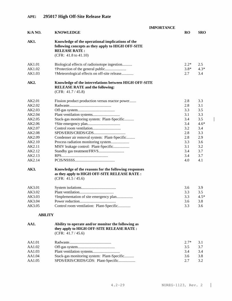
NUREG-1123, Rev. 2 |4.2-29
APE: 295017 High Off-Site Release Rate
IMPORTANCE K/A NO. KNOWLEDGE RO SRO
AK1. Knowledge of the operational implications of thefollowing concepts as they apply to HIGH OFF-SITERELEASE RATE :(CFR: 41.8 to 41.10)
AK1.01 Biological effects of radioisotope ingestion.......... 2.2* 2.5AK1.02 †Protection of the general public...................... 3.8* 4.3*AK1.03 †Meteorological effects on off-site release............ 2.7 3.4
AK2. Knowledge of the interrelations between HIGH OFF-SITERELEASE RATE and the following:(CFR: 41.7 / 45.8)
AK2.01 Fission product production versus reactor power....... 2.8 3.3AK2.02 Radwaste.............................................. 2.8 3.1AK2.03 Off-gas system........................................ 3.3 3.5AK2.04 Plant ventilation systems............................. 3.1 3.3AK2.05 Stack-gas monitoring system: Plant-Specific.......... 3.4 3.5 |AK2.06 †Site emergency plan................................... 3.4 4.6*AK2.07 Control room ventilation.............................. 3.2 3.4AK2.08 SPDS/ERIS/CRIDS/GDS................................... 2.8 3.3AK2.09 Condenser air removal system: Plant-Specific......... 2.8 2.9AK2.10 Process radiation monitoring system................... 3.3 3.6AK2.11 MSIV leakage control: Plant-Specific................. 3.1 3.2AK2.12 Standby gas treatment/FRVS............................ 3.4 3.7AK2.13 RPS................................................... 3.4 3.7AK2.14 PCIS/NSSSS............................................ 4.0 4.1
AK3. Knowledge of the reasons for the following responsesas they apply to HIGH OFF-SITE RELEASE RATE :(CFR: 41.5 / 45.6)
AK3.01 System isolations..................................... 3.6 3.9AK3.02 Plant ventilation..................................... 3.3 3.5AK3.03 †Implementation of site emergency plan................. 3.3 4.5*AK3.04 Power reduction....................................... 3.6 3.8AK3.05 Control room ventilation: Plant-Specific............. 3.3 3.6
ABILITY
AA1. Ability to operate and/or monitor the following as they apply to HIGH OFF-SITE RELEASE RATE :
(CFR: 41.7 / 45.6)
AA1.01 Radwaste.............................................. 2.7* 3.1AA1.02 Off-gas system........................................ 3.5 3.7AA1.03 Plant ventilation systems............................. 3.4 3.4AA1.04 Stack-gas monitoring system: Plant-Specific.......... 3.6 3.8AA1.05 SPDS/ERIS/CRIDS/GDS: Plant-Specific.................. 2.7 3.2

NUREG-1123, Rev. 2 |4.2-30
APE: 295017 High Off-Site Release Rate
IMPORTANCE K/A NO. ABILITY RO SRO
AA1.06 Condenser air removal system: Plant-Specific......... 3.2 3.2AA1.07 Process radiation monitoring system................... 3.4 3.6AA1.08 MSIV leakage control: Plant-Specific................. 3.1 3.4AA1.09 Standby gas treatment/FRVS............................ 3.6 3.8AA1.10 RPS................................................... 3.6 3.7AA1.11 PCIS/NSSSS............................................ 3.9 4.1AA1.12 †Meteorological data................................... 2.5* 3.9
AA2. Ability to determine and/or interpret the following asthey apply to HIGH OFF-SITE RELEASE RATE :(CFR: 41.10 / 43.5 / 45.13)
AA2.01 †Off-site release rate: Plant-Specific................ 2.9* 4.2*AA2.02 †Total number of curies released: Plant-Specific...... 2.4* 3.5*AA2.03 †Radiation levels: Plant-Specific..................... 3.1 3.9AA2.04 †Source of off-site release............................ 3.6 4.3*AA2.05 †Meteorological data................................... 2.5 3.8

NUREG-1123, Rev. 2 |4.2-31
APE: 295018 Partial or Complete Loss of Component Cooling Water
IMPORTANCE K/A NO. KNOWLEDGE RO SRO
AK1. Knowledge of the operational implications of thefollowing concepts as they apply to PARTIAL ORCOMPLETE LOSS OF COMPONENT COOLING WATER :(CFR: 41.8 to 41.10)
AK1.01 Effects on component/system operations................ 3.5 3.6
AK2. Knowledge of the interrelations between PARTIAL ORCOMPLETE LOSS OF COMPONENT COOLING WATER and thefollowing:(CFR: 41.7 / 45.8)
AK2.01 System loads.......................................... 3.3 3.4AK2.02 Plant operations...................................... 3.4 3.6
AK3. Knowledge of the reasons for the following responsesas they apply to PARTIAL OR COMPLETE LOSS OF COMPONENTCOOLING WATER :(CFR: 41.5 / 45.6)
AK3.01 Isolation of non-essential heat loads: Plant-Specific 2.9 3.2AK3.02 Reactor power reduction............................... 3.3 3.4AK3.03 Securing individual components (prevent equipment
damage)............................................... 3.1 3.3AK3.04 Starting standby pump................................. 3.3 3.3AK3.05 Placing standby heat exchanger in service............. 3.2 3.3AK3.06 Increasing cooling water flow to heat exchangers...... 3.3 3.3AK3.07 Cross-connecting with backup systems.................. 3.1 3.2
ABILITY
AA1. Ability to operate and/or monitor the following as they apply to PARTIAL OR COMPLETE LOSS OF COMPONENT
COOLING WATER :(CFR: 41.7 / 45.6)
AA1.01 Backup systems........................................ 3.3 3.4AA1.02 System loads.......................................... 3.3 3.4AA1.03 Affected systems so as to isolate damaged portions.... 3.3 3.4
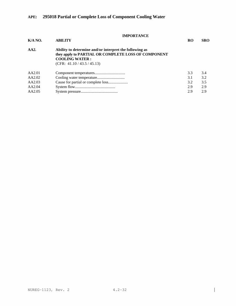
NUREG-1123, Rev. 2 |4.2-32
APE: 295018 Partial or Complete Loss of Component Cooling Water
IMPORTANCE K/A NO. ABILITY RO SRO
AA2. Ability to determine and/or interpret the following asthey apply to PARTIAL OR COMPLETE LOSS OF COMPONENT COOLING WATER :(CFR: 41.10 / 43.5 / 45.13)
AA2.01 Component temperatures................................ 3.3 3.4AA2.02 Cooling water temperature............................. 3.1 3.2AA2.03 Cause for partial or complete loss.................... 3.2 3.5AA2.04 System flow........................................... 2.9 2.9AA2.05 System pressure....................................... 2.9 2.9

NUREG-1123, Rev. 2 |4.2-33
APE: 295019 Partial or Complete Loss of Instrument Air
IMPORTANCE K/A NO. KNOWLEDGE RO SRO
AK1. Knowledge of the operational implications of thefollowing concepts as they apply to PARTIAL ORCOMPLETE LOSS OF INSTRUMENT AIR :(CFR: 41.8 to 41.10)
None |
AK2. Knowledge of the interrelations between PARTIAL ORCOMPLETE LOSS OF INSTRUMENT AIR and the following:(CFR: 41.7 / 45.8)
AK2.01 CRD hydraulics........................................ 3.8 3.9AK2.02 Component cooling water............................... 2.9 3.0AK2.03 Reactor feedwater..................................... 3.2 3.3AK2.04 Reactor water cleanup................................. 2.8 2.8AK2.05 Main steam system..................................... 3.4 3.4AK2.06 Offgas system......................................... 2.8 2.9AK2.07 Condensate system..................................... 3.2 3.2AK2.08 Plant ventilation..................................... 2.8 2.9AK2.09 Containment........................................... 3.3 3.3AK2.10 Fuel pool cooling..................................... 2.8 2.8AK2.11 Radwaste.............................................. 2.5 2.6AK2.12 Standby gas treatment/FRVS............................ 3.3 3.4AK2.13 Isolation condenser: Plant-Specific.................. 3.2* 3.2*AK2.14 Plant air systems..................................... 3.2 3.2AK2.15 Standby liquid control system......................... 2.3* 2.6AK2.16 Reactor core isolation cooling........................ 2.8 2.8AK2.17 High pressure coolant injection: Plant-Specific...... 2.7 2.7AK2.18 ADS: Plant-Specific.................................. 3.5 3.5AK2.19 RHR/LPCI: Plant-Specific............................. 2.7 2.8
AK3. Knowledge of the reasons for the following responsesas they apply to PARTIAL OR COMPLETE LOSS OFINSTRUMENT AIR :(CFR: 41.5 / 45.6)
AK3.01 Backup air system supply: Plant-Specific............. 3.3 3.4AK3.02 Standby air compressor operation...................... 3.5 3.4AK3.03 Service air isolations: Plant-Specific............... 3.2 3.2
ABILITY
AA1. Ability to operate and/or monitor the following asthey apply to PARTIAL OR COMPLETE LOSS OF INSTRUMENTAIR :(CFR: 41.7 / 45.6)
AA1.01 Backup air supply..................................... 3.5 3.3
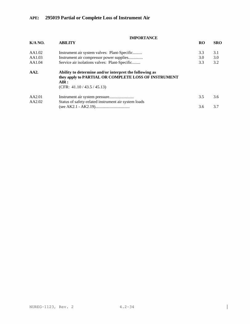
NUREG-1123, Rev. 2 |4.2-34
APE: 295019 Partial or Complete Loss of Instrument Air
IMPORTANCE K/A NO. ABILITY RO SRO
AA1.02 Instrument air system valves: Plant-Specific......... 3.3 3.1AA1.03 Instrument air compressor power supplies.............. 3.0 3.0AA1.04 Service air isolations valves: Plant-Specific........ 3.3 3.2
AA2. Ability to determine and/or interpret the following asthey apply to PARTIAL OR COMPLETE LOSS OF INSTRUMENTAIR :(CFR: 41.10 / 43.5 / 45.13)
AA2.01 Instrument air system pressure........................ 3.5 3.6AA2.02 Status of safety-related instrument air system loads
(see AK2.1 - AK2.19).................................. 3.6 3.7

NUREG-1123, Rev. 2 |4.2-35
APE: 295020 Inadvertent Containment Isolation
IMPORTANCE K/A NO. KNOWLEDGE RO SRO
AK1. Knowledge of the operational implications of the following concepts as they apply to INADVERTENT CONTAINMENT ISOLATION :
(CFR: 41.8 to 41.10)
AK1.01 Loss of normal heat sink.............................. 3.7 3.9AK1.02 Power/reactivity control.............................. 3.5 3.8AK1.03 Water chemistry....................................... 2.3 2.5AK1.04 Bottom head thermal stratification.................... 2.5 2.8AK1.05 Loss of drywell/containment cooling................... 3.3 3.6
AK2. Knowledge of the interrelations between INADVERTENTCONTAINMENT ISOLATION and the following:(CFR: 41.7 / 45.8)
AK2.01 Main steam system..................................... 3.6 3.7 |AK2.02 Sampling system....................................... 2.6 2.8AK2.03 Drywell/containment ventilation/cooling: Plant-
Specific.............................................. 3.1 3.3AK2.04 RWCU system........................................... 3.1 3.1AK2.05 Isolation condenser: Plant-Specific.................. 4.2* 4.2AK2.06 HPCI: Plant-Specific................................. 3.8 3.8AK2.07 RCIC: Plant-Specific................................. 3.4 3.4AK2.08 Traversing in-core probes: Plant-Specific............ 2.5* 2.6AK2.09 RHR/shutdown cooling: Plant-Specific................. 3.1 3.3AK2.10 Drywell equipment/floor drain sumps................... 2.9 3.1AK2.11 Standby gas treatment system/FRVS: Plant-Specific.... 3.2 3.4AK2.12 Instrument air/nitrogen: Plant-Specific.............. 3.1 3.2
AK3. Knowledge of the reasons for the following responsesas they apply to INADVERTENT CONTAINMENT ISOLATION:(CFR: 41.5 / 45.6)
AK3.01 Reactor SCRAM........................................... 3.8 3.8AK3.02 Drywell/containment pressure response................... 3.3 3.5AK3.03 Drywell/containment temperature response................ 3.2 3.2AK3.04 Reactor pressure response............................... 4.1 4.1AK3.05 Reactor water level response............................ 3.8 3.9AK3.06 Suppression pool water level response................... 3.3 3.4AK3.07 Suppression pool temperature response................... 3.4 3.6AK3.08 Suppression chamber pressure response................... 3.3 3.5

NUREG-1123, Rev. 2 |4.2-36
APE: 295020 Inadvertent Containment Isolation
IMPORTANCE K/A NO. ABILITY RO SRO
AA1. Ability to operate and/or monitor the following as they apply to INADVERTENT CONTAINMENT ISOLATION :(CFR: 41.7 / 45.6)
AA1.01 PCIS/NSSSS............................................ 3.6 3.6AA1.02 Drywell ventilation/cooling system.................... 3.2 3.2AA1.03 Containment ventilation system: Plant-Specific....... 2.9 3.1
AA2. Ability to determine and/or interpret the following asthey apply to INADVERTENT CONTAINMENT ISOLATION :(CFR: 41.10 / 43.5 / 45.13)
AA2.01 Drywell/containment pressure.......................... 3.6 3.7AA2.02 Drywell/containment temperature....................... 3.3 3.4AA2.03 Reactor power......................................... 3.7 3.7AA2.04 Reactor pressure...................................... 3.9 3.9AA2.05 Reactor water level................................... 3.6 3.6AA2.06 Cause of isolation.................................... 3.4 3.8

NUREG-1123, Rev. 2 |4.2-37
APE: 295021 Loss of Shutdown Cooling
IMPORTANCE K/A NO. KNOWLEDGE RO SRO
AK1. Knowledge of the operational implications of thefollowing concepts as they apply to LOSS OF SHUTDOWNCOOLING :(CFR: 41.8 to 41.10)
AK1.01 Decay heat............................................ 3.6 3.8AK1.02 Thermal stratification................................ 3.3 3.4AK1.03 Adequate core cooling................................. 3.9 3.9AK1.04 Natural circulation................................... 3.6 3.7
AK2. Knowledge of the interrelations between LOSS OFSHUTDOWN COOLING and the following:(CFR: 41.7 / 45.8)
AK2.01 Reactor water temperature............................. 3.6 3.7AK2.02 Reactor water cleanup................................. 3.2 3.3AK2.03 RHR/shutdown cooling.................................. 3.6 3.6AK2.04 Component cooling water systems: Plant-Specific...... 3.0 3.1AK2.05 Fuel pool cooling and cleanup system.................. 2.7 2.8AK2.06 Reactor vessel headspray: Plant-Specific............. 2.5 2.6AK2.07 Reactor recirculation................................. 3.1 3.2
AK3. Knowledge of the reasons for the following responsesas they apply to LOSS OF SHUTDOWN COOLING :(CFR: 41.5 / 45.6)
AK3.01 Raising reactor water level........................... 3.3 3.4AK3.02 Feeding and bleeding reactor vessel................... 3.3 3.4AK3.03 Increasing drywell cooling............................ 2.9 2.9AK3.04 Maximizing reactor water cleanup flow................. 3.3 3.4AK3.05 Establishing alternate heat removal flow paths........ 3.6 3.8
ABILITY
AA1. Ability to operate and/or monitor the following as they apply to LOSS OF SHUTDOWN COOLING :
(CFR: 41.7 / 45.6)
AA1.01 Reactor water cleanup system.......................... 3.4 3.4AA1.02 RHR/shutdown cooling.................................. 3.5 3.5AA1.03 Component cooling water systems: Plant-Specific...... 3.1 3.1AA1.04 Alternate heat removal methods........................ 3.7 3.7AA1.05 Reactor recirculation................................. 3.0 3.0AA1.06 Containment/ drywell temperature...................... 2.8 3.0

NUREG-1123, Rev. 2 |4.2-38
APE: 295021 Loss of Shutdown Cooling
IMPORTANCE K/A NO. ABILITY RO SRO
AA2. Ability to determine and/or interpret the following asthey apply to LOSS OF SHUTDOWN COOLING :(CFR: 41.10 / 43.5 / 45.13)
AA2.01 Reactor water heatup/cooldown rate .................... 3.5 3.6AA2.02 RHR/shutdown cooling system flow .................... 3.4 3.4AA2.03 Reactor water level ................................... 3.5 3.5|AA2.04 Reactor water temperature ............................. 3.6 3.6|AA2.05 Reactor vessel metal temperature ...................... 3.4 3.5|AA2.06 Reactor pressure ...................................... 3.2 3.3AA2.07 Reactor recirculation flow ............................ 2.9 3.1

NUREG-1123, Rev. 2 |4.2-39
APE: 295022 Loss of CRD Pumps
IMPORTANCE K/A NO. KNOWLEDGE RO SRO
AK1. Knowledge of the operational implications of the following concepts as they apply to LOSS OF CRD PUMPS:(CFR: 41.8 to 41.10)
AK1.01 Reactor pressure vs. rod insertion capability......... 3.3 3.4AK1.02 Reactivity control.................................... 3.6 3.7
AK2. Knowledge of the interrelations between LOSS OF CRDPUMPS and the following:(CFR: 41.7 / 45.8)
AK2.01 Recirculation system: Plant-Specific................. 2.8 3.0AK2.02 CRD mechanism......................................... 3.1 3.1AK2.03 Accumulator pressures................................. 3.4 3.4AK2.04 Reactor water level................................... 2.5 2.7AK2.05 Reactor water cleanup: Plant-Specific................ 2.4 2.5AK2.06 Shared components with other units: Plant-Specific... 2.6 2.8AK2.07 Reactor pressure (SCRAM assist): Plant-Specific...... 3.4 3.6
AK3. Knowledge of the reasons for the following responsesas they apply to LOSS OF CRD PUMPS:(CFR: 41.5 / 45.6)
AK3.01 Reactor SCRAM......................................... 3.7* 3.9*AK3.02 CRDM high temperature................................. 2.9 3.1
ABILITY
AA1. Ability to operate and/or monitor the following as they apply to LOSS OF CRD PUMPS:
(CFR: 41.7 / 45.6)
AA1.01 CRD hydraulic system.................................. 3.1 3.2AA1.02 RPS................................................... 3.6 3.6AA1.03 Recirculation system: Plant-Specific................. 2.7 2.8AA1.04 Reactor water cleanup system: Plant-Specific......... 2.5 2.6
AA2. Ability to determine and/or interpret the following asthey apply to LOSS OF CRD PUMPS :(CFR: 41.10 / 43.5 / 45.13)
AA2.01 Accumulator pressure.................................. 3.5 3.6AA2.02 CRD system status..................................... 3.3 3.4AA2.03 CRD mechanism temperatures............................ 3.1 3.2

NUREG-1123, Rev. 2 |4.2-40
APE: 295023 Refueling Accidents
IMPORTANCE K/A NO. KNOWLEDGE RO SRO
AK1. Knowledge of the operational implications of thefollowing concepts as they apply to REFUELINGACCIDENTS :(CFR: 41.8 to 41.10)
AK1.01 Radiation exposure hazards............................ 3.6 4.1AK1.02 Shutdown margin....................................... 3.2 3.6AK1.03 Inadvertent criticality............................... 3.7 4.0
AK2. Knowledge of the interrelations between REFUELINGACCIDENTS and the following:(CFR: 41.7 / 45.8)
AK2.01 Fuel handling equipment............................... 3.3 3.7AK2.02 Fuel pool cooling and cleanup system.................. 2.9 3.2AK2.03 Radiation monitoring equipment........................ 3.4 3.6AK2.04 RMCS/Rod control and information system............... 3.2 3.4AK2.05 Secondary containment ventilation..................... 3.5 3.7AK2.06 Containment ventilation: Mark-III.................... 3.4 3.8AK2.07 Standby gas treatment/FRVS............................ 3.6 3.9
AK3. Knowledge of the reasons for the following responsesas they apply to REFUELING ACCIDENTS :(CFR: 41.5 / 45.6)
AK3.01 Refueling floor evacuation............................ 3.6 4.3*AK3.02 Interlocks associated with fuel handling equipment.... 3.4 3.8AK3.03 Ventilation isolation................................. 3.3 3.6AK3.04 Non-coincident SCRAM function......................... 3.0 3.5AK3.05 Initiation of SLC/shut-down cooling: Plant-
Specific(BWR-1)....................................... 3.5 4.0
ABILITY
AA1. Ability to operate and/or monitor the following asthey apply to REFUELING ACCIDENTS :(CFR: 41.7 / 45.6)
AA1.01 Secondary containment ventilation..................... 3.3 3.5AA1.02 Fuel pool cooling and cleanup system.................. 2.9 3.1AA1.03 Fuel handling equipment............................... 3.3 3.6AA1.04 Radiation monitoring equipment........................ 3.4 3.7AA1.05 Fuel transfer system: Plant-Specific................. 2.8 3.5AA1.06 Neutron monitoring.................................... 3.3 3.4AA1.07 Standby gas treatment/FRVS............................ 3.6 3.6AA1.08 †Containment building ventilation: Mark-III......... 3.3 3.4

NUREG-1123, Rev. 2 |4.2-41
APE: 295023 Refueling Accidents
IMPORTANCE K/A NO. ABILITY RO SRO
AA2. Ability to determine and/or interpret the following asthey apply to REFUELING ACCIDENTS :(CFR: 41.10 / 43.5 / 45.13)
AA2.01 Area radiation levels................................. 3.6 4.0AA2.02 Fuel pool level....................................... 3.4 3.7AA2.03 Airborne contamination levels......................... 3.3* 3.8*AA2.04 †Occurrence of fuel handling accident.................. 3.4 4.1AA2.05 †Entry conditions of emergency plan.................... 3.2 4.6*

NUREG-1123, Rev. 2 |4.2-42
APE: 600000 Plant Fire On Site
IMPORTANCE K/A NO. KNOWLEDGE RO SRO
AK1 Knowledge of the operation applications of the following concepts as they apply to Plant Fire On Site:
AK1.01 Fire Classifications by type . . . . . . . . . . . . . . . . . . . . . . . . . . . . . . . . . . . . . . . . . . . . . . 2.5 2.8
AK1.02 Fire Fighting . . . . . . . . . . . . . . . . . . . . . . . . . . . . . . . . . . . . . . . . . . . . . . . . . . . . . . . . . . . 2.9 3.1
AK2. Knowledge of the interrelations between PLANT FIRE ON SITE and the following:
AK2.01 Sensors / detectors and valves . . . . . . . . . . . . . . . . . . . . . . . . . . . . . . . . . . . . . . . . . . . . 2.6 2.7AK2.02 Controllers and positioners . . . . . . . . . . . . . . . . . . . . . . . . . . . . . . . . . . . . . . . . . . . . . . 2.4 2.5AK2.03 Motors . . . . . . . . . . . . . . . . . . . . . . . . . . . . . . . . . . . . . . . . . . . . . . . . . . . . . . . . . . . . . . . 2.5 2.6AK2.04 Breakers / relays / and disconnects . . . . . . . . . . . . . . . . . . . . . . . . . . . . . . . . . . . . . . . . . 2.5 2.6
AK3 Knowledge of the reasons for the following responsesas they apply to PLANT FIRE ON SITE:
AK3.01 Installation of fire detectors . . . . . . . . . . . . . . . . . . . . . . . . . . . . . . . . . . . . . . . . . . . . . . 2.0 2.1AK3.02 Steps called our in the site fire protection plant /
fire protection system manual / and fire zone manual . . . . . . . . . . . . . . . . . . . . . . . . . 2.2 2.8AK3.03 Fire detector surveillance test . . . . . . . . . . . . . . . . . . . . . . . . . . . . . . . . . . . . . . . . . . . . . 2.0 2.2AK3.04 Actions contained in the abnormal procedure for plant
fire on site . . . . . . . . . . . . . . . . . . . . . . . . . . . . . . . . . . . . . . . . . . . . . . . . . . . . . . . . . . . . . 2.8 3.4

NUREG-1123, Rev. 2 |4.2-43
APE: 600000 Plant Fire On Site
IMPORTANCE K/A NO. ABILITY RO SRO
AA1 Ability to operate and / or monitor the following as theyapply to PLANT FIRE ON SITE:
AA1.01 Respirator air pack . . . . . . . . . . . . . . . . . . . . . . . . . . . . . . . . . . . . . . . . . . . . . . . . . . . . . . 3.0 2.9AA1.02 Re-installation of fire detector . . . . . . . . . . . . . . . . . . . . . . . . . . . . . . . . . . . . . . . . . . . . 1.8 1.9AA1.03 Bypass of fire zone detector . . . . . . . . . . . . . . . . . . . . . . . . . . . . . . . . . . . . . . . . . . . . . . 1.8 2.2AA1.04 Bypass of heat detector . . . . . . . . . . . . . . . . . . . . . . . . . . . . . . . . . . . . . . . . . . . . . . . . . . 1.9 2.2AA1.05 Plant and control room ventilation systems . . . . . . . . . . . . . . . . . . . . . . . . . . . . . . . . . . 3.0 3.1AA1.06 Fire alarm . . . . . . . . . . . . . . . . . . . . . . . . . . . . . . . . . . . . . . . . . . . . . . . . . . . . . . . . . . . . . 3.0 3.0AA1.07 Fire alarm reset panel . . . . . . . . . . . . . . . . . . . . . . . . . . . . . . . . . . . . . . . . . . . . . . . . . . . . 2.3 2.4AA1.08 Fire fighting equipment used on each class of fire . . . . . . . . . . . . . . . . . . . . . . . . . . . . 2.6 2.9AA1.09 Plant fire zone panel (including detector location) . . . . . . . . . . . . . . . . . . . . . . . . . . . . 2.5 2.7
AA2 Ability to determine and interpret the following as they apply to PLANT FIRE ON SITE:
AA2.01 Gas treatment system . . . . . . . . . . . . . . . . . . . . . . . . . . . . . . . . . . . . . . . . . . . . . . . . . . . 2.2 2.3AA2.02 Damper position . . . . . . . . . . . . . . . . . . . . . . . . . . . . . . . . . . . . . . . . . . . . . . . . . . . . . . . . 2.8 2.9AA2.03 Fire alarm . . . . . . . . . . . . . . . . . . . . . . . . . . . . . . . . . . . . . . . . . . . . . . . . . . . . . . . . . . . . . 2.8 3.2AA2.04 The fire's extent of potential operational damage
to plant equipment . . . . . . . . . . . . . . . . . . . . . . . . . . . . . . . . . . . . . . . . . . . . . . . . . . . . . . 2.8 3.1AA2.05 Ventilation alignment necessary to secure
affected area . . . . . . . . . . . . . . . . . . . . . . . . . . . . . . . . . . . . . . . . . . . . . . . . . . . . . . . . . . . 2.9 3.0AA2.06 Need for pressurizing control room
(recirculating mode) . . . . . . . . . . . . . . . . . . . . . . . . . . . . . . . . . . . . . . . . . . . . . . . . . . . . 2.5 2.8AA2.07 Whether malfunction is due to common-mode electrical
failures . . . . . . . . . . . . . . . . . . . . . . . . . . . . . . . . . . . . . . . . . . . . . . . . . . . . . . . . . . . . . . . . 2.6 3.0AA2.08 Limits of affected areaAA2.09 That a failed fire alarm detector exists . . . . . . . . . . . . . . . . . . . . . . . . . . . . . . . . . . . . . . 2.4 2.8AA2.10 Time limit of long-term-breathing air system for
control room . . . . . . . . . . . . . . . . . . . . . . . . . . . . . . . . . . . . . . . . . . . . . . . . . . . . . . . . . . . 2.9 3.1AA2.11 Time limit for use of respirators . . . . . . . . . . . . . . . . . . . . . . . . . . . . . . . . . . . . . . . . . . 2.9 3.0AA2.12 Location of vital equipment within fire zone . . . . . . . . . . . . . . . . . . . . . . . . . . . . . . . . . 3.1 3.5AA2.13 Need for emergency plant shutdown . . . . . . . . . . . . . . . . . . . . . . . . . . . . . . . . . . . . . . . 3.2 3.8AA2.14 Equipment that will be affected by fire suppression
activities in each zone . . . . . . . . . . . . . . . . . . . . . . . . . . . . . . . . . . . . . . . . . . . . . . . . . . . 3.0 3.6AA2.15 Requirements for establishing a fire watch . . . . . . . . . . . . . . . . . . . . . . . . . . . . . . . . . . 2.3 3.5AA2.16 Vital equipment and control systems to be maintained
and operated during a fire . . . . . . . . . . . . . . . . . . . . . . . . . . . . . . . . . . . . . . . . . . . . . . . . 3.0 3.5AA2.17 Systems that may be affected by the fire . . . . . . . . . . . . . . . . . . . . . . . . . . . . . . . . . . . . 3.1 3.6

NUREG-1123, Rev. 2 |4.2-44
This page left blank

NUREG-1123, Rev. 2 |5-1
5 Components page
291001 Valves 5-3291002 Sensors and Detectors 5-4291003 Controllers and Positioners 5-6291004 Pumps 5-7291005 Motors and Generators 5-9291006 Heat Exchangers and Condensers 5-10291007 Demineralizers and Ion Exchangers 5-11291008 Breakers, Relays and Disconnects 5-12

NUREG-1123, Rev. 2 |5-2
This page left blank.

NUREG-1123, Rev. 2 |5-3
COMPONENT: 291001 Valves (CFR: 41.3)
IMPORTANCE K/A NO. KNOWLEDGE RO SRO
K1.01 The operation of safety valves 3.4 3.5
K1.02 The operation of relief valves 3.4 3.6
K1.03 The relationship of valve position to flow rate andback pressure 2.7 2.8
K1.04 Valve design for a given failed-valve position (open,closed, and as-is positions; spring loaded valves;hydraulic, pneumatically controlled valves; electricmotor-driven valves) 2.7 2.8
K1.05 The significance of stem position (valve status) forgate valves 2.9 2.8
K1.06 Safety concerns in the use of gate valves (protectvalves seals, open slowly) 2.7 2.7
K1.07 Cautions for placing a valve controller in manual mode 3.4 3.4
K1.08 Emergency operation of MOV with motor inoperable 3.4 3.5
K1.09 The stroke test for a valve, including the use of a
stopwatch 2.7 2.7
K1.10 Principles of operation and purpose of check valves 3.1 3.1
K1.11 Operation of manual valves and verification of
position with indicator lights 3.2 3.2
K1.12 Reason for using globe valves versus gates valves forthrottling 2.6 2.8

NUREG-1123, Rev. 2 |5-4
COMPONENT: 291002 Sensors/Detectors(CFR: 41.7)
IMPORTANCE K/A NO. KNOWLEDGE RO SRO
Flow
K1.01 Operation of venturis and orifices 2.4 2.5
K1.02 Temperature compensation requirements 2.4 2.5
K1.03 Effects of gas or steam on liquid flow rate
indications (erroneous reading) 2.5 2.6
K1.04 Modes of failure 2.9 3.1
K1.05 Operation of a flow D/P cell type flow detector 3.1 3.1
Level
K1.06 Temperature/pressure compensation requirements 2.8 2.9
K1.07 Operation of a differential pressure level detector 3.2 3.2
K1.08 Effects of operating environment (pressure,temperature, and radiation) 2.8 2.9
K1.09 Modes of failure 3.3 3.3
Pressure
K1.10 Theory of operation of bourdon tubes, diaphragms,bellows, and pressure detectors 2.4 2.5
K1.11 Effects of operating environment (pressure,temperature, radiation) 2.3 2.5
K1.12 Operation of a pressure D/P cell 2.8 2.9
K1.13 Modes of failure 2.9 3.1
Temperature
K1.14 Theory of operation of T/C, RTD, thermostats,thermometers (expanding fluid) 2.3* 2.4
K1.15 Indications of failure modes of T/C, RTD, thermometers 2.6 2.8
Position Detector_
K1.16 Failure modes of reed switches, LVDT, limit switches, and potentiometers 2.5 2.7

NUREG-1123, Rev. 2 |5-5
COMPONENT: 291002 Sensors/Detectors(CFR: 41.7)
IMPORTANCE K/A NO. KNOWLEDGE RO SRO
K1.17 Applications of reed switches, magnets, LVDT,potentiometers, and limit switches 2.3* 2.4
Electrical
K1.18 Applications of voltmeters, ammeters, frequency, andground detectors 2.2* 2.4
Nuclear Instrumentation
K1.19 Operation of fission chambers, ion chambers 3.0 3.1
K1.20 Neutron monitoring indication units 3.2 3.2
K1.21 Effects of voltage changes on neutron detectorperformance 2.8 2.9
K1.22 Failure modes of fission chambers, ion chambers, andproportional counters 3.0 3.1
Radiation Detection
K1.23 Operation of ion chambers, G-M tubes and scintillationdetectors 2.8 2.9
K1.24 Use of portable radiation monitoring instruments 3.1 3.2
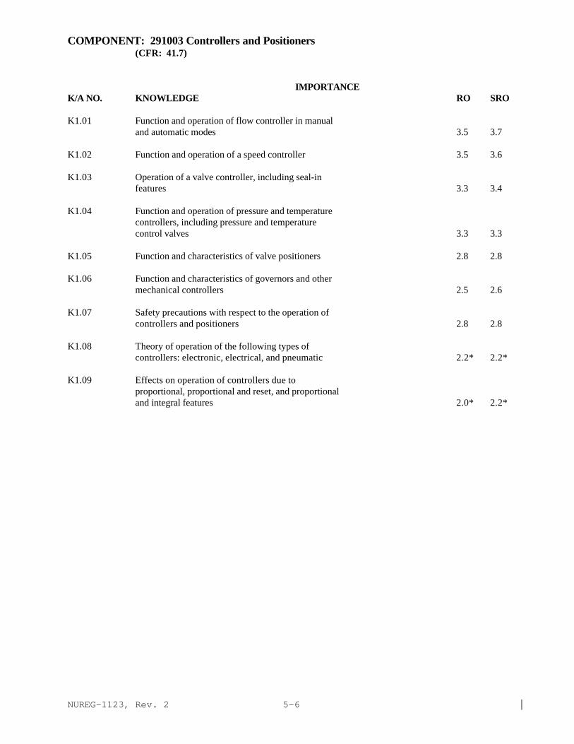
NUREG-1123, Rev. 2 |5-6
COMPONENT: 291003 Controllers and Positioners(CFR: 41.7)
IMPORTANCE K/A NO. KNOWLEDGE RO SRO
K1.01 Function and operation of flow controller in manualand automatic modes 3.5 3.7
K1.02 Function and operation of a speed controller 3.5 3.6
K1.03 Operation of a valve controller, including seal-infeatures 3.3 3.4
K1.04 Function and operation of pressure and temperaturecontrollers, including pressure and temperaturecontrol valves 3.3 3.3
K1.05 Function and characteristics of valve positioners 2.8 2.8
K1.06 Function and characteristics of governors and othermechanical controllers 2.5 2.6
K1.07 Safety precautions with respect to the operation ofcontrollers and positioners 2.8 2.8
K1.08 Theory of operation of the following types ofcontrollers: electronic, electrical, and pneumatic 2.2* 2.2*
K1.09 Effects on operation of controllers due toproportional, proportional and reset, and proportionaland integral features 2.0* 2.2*

NUREG-1123, Rev. 2 |5-7
COMPONENT: 291004 Pumps(CFR: 41.3)
IMPORTANCE K/A NO. KNOWLEDGE RO SRO
Centrifugal
K1.01 Identification, symptoms, and consequences ofcavitation 3.2 3.2
K1.02 Reasons for venting a centrifugal pump 2.8 2.8
K1.03 Consequences of air binding 2.8 2.9
K1.04 Consequences of operating a pump dead headed or forextended recirculation times 3.0 3.1
K1.05 Discuss relationships among head, flow, speed, andpower 2.8 2.9
K1.06 Need for net positive suction head (NPSH); effects ofloss of suction 3.3 3.3
K1.07 Starting current and operating current interpretation 2.8 2.8
K1.08 Purpose of starting a pump with discharge valve closed 2.8 2.8
K1.09 Pressure and flow relationship of pumps in parallel 2.3* 2.4*
K1.10 Pressure and flow relationship of pumps in series 2.3* 2.4*
K1.11 Definition of pump shutoff head 2.4 2.5
K1.12 "Runout" of a centrifugal pump (definition,indications, causes, effects, and corrective measures) 2.8 2.8
K1.13 Principles of operation of a centrifugal pump 2.6 2.7
K1.14 Relationship between flow from a pump and suctionheads 2.5 2.5
K1.15 Purpose of pump minimum flow requirements
Positive Displacement 2.9 2.9
K1.16 Discuss relationship among head, flow, speed, andpower 2.5 2.7
K1.17 Net positive suction head (NSPH) requirements for apositive displacement pump 2.5 2.6
K1.18 Consequences of operating a positive displacement pump against a closed flow path 3.3 3.3

NUREG-1123, Rev. 2 |5-8
COMPONENT: 291004 Pumps(CFR: 41.3)
IMPORTANCE K/A NO. KNOWLEDGE RO SRO
K1.19 Functions and characteristics of positive displacement pumps 2.6 2.6
K1.20 Reason for starting a positive displacement pump with the discharge valve open; need to clear the flow path 3.1 3.1
K1.21 Safety procedures and precautions associated with positive displacement pumps 3.1 3.0

NUREG-1123, Rev. 2 |5-9
COMPONENT: 291005 Motors and Generators(CFR: 41.7)
IMPORTANCE K/A NO. KNOWLEDGE RO SRO
K1.01 Locked motor rotor, recognition from motor parameters 2.6 2.6
K1.02 Potential consequences of overheating motor insulationor motor bearings 2.6 2.7
K1.03 Causes of excessive current in motors, such as lowvoltage, overloading , and mechanical binding 2.6 2.7
K1.04 Relationship between pump motor current (ammeterreading) and the following: pump fluid flow, head,speed, and stator temperature 2.7 2.7
K1.05 Explain the difference between starting current andoperating (running) current in a motor 2.6 2.7
K1.06 Reason for limiting the number of motor starts in agiven time period 2.9 3.1
K1.07 Electrical units: volts, amps, A.C., D.C., and hertz 2.6 2.6
K1.08 Consequences of overexcited/underexcited 2.5 2.6
K1.09 †Interrelations of the following: VARs, Watts, Amps,Volts, Power factor 2.3* 2.6
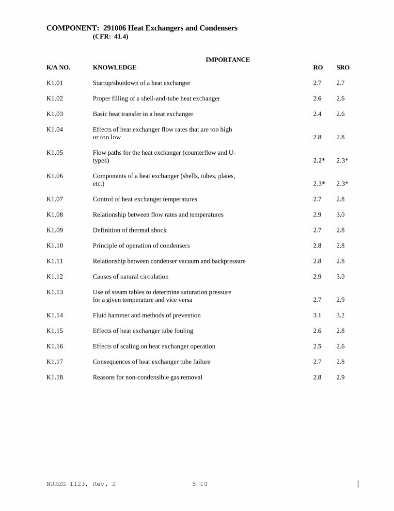
NUREG-1123, Rev. 2 |5-10
COMPONENT: 291006 Heat Exchangers and Condensers(CFR: 41.4)
IMPORTANCE K/A NO. KNOWLEDGE RO SRO
K1.01 Startup/shutdown of a heat exchanger 2.7 2.7
K1.02 Proper filling of a shell-and-tube heat exchanger 2.6 2.6
K1.03 Basic heat transfer in a heat exchanger 2.4 2.6
K1.04 Effects of heat exchanger flow rates that are too highor too low 2.8 2.8
K1.05 Flow paths for the heat exchanger (counterflow and U-types) 2.2* 2.3*
K1.06 Components of a heat exchanger (shells, tubes, plates,etc.) 2.3* 2.3*
K1.07 Control of heat exchanger temperatures 2.7 2.8
K1.08 Relationship between flow rates and temperatures 2.9 3.0
K1.09 Definition of thermal shock 2.7 2.8
K1.10 Principle of operation of condensers 2.8 2.8
K1.11 Relationship between condenser vacuum and backpressure 2.8 2.8
K1.12 Causes of natural circulation 2.9 3.0
K1.13 Use of steam tables to determine saturation pressurefor a given temperature and vice versa 2.7 2.9
K1.14 Fluid hammer and methods of prevention 3.1 3.2
K1.15 Effects of heat exchanger tube fouling 2.6 2.8
K1.16 Effects of scaling on heat exchanger operation 2.5 2.6
K1.17 Consequences of heat exchanger tube failure 2.7 2.8
K1.18 Reasons for non-condensible gas removal 2.8 2.9

NUREG-1123, Rev. 2 |5-11
COMPONENT: 291007 Demineralizers and Ion Exchangers(CFR: 41.3)
IMPORTANCE K/A NO. KNOWLEDGE RO SRO
K1.01 Effect of excessive differential pressure on demineralizer performance 2.6 2.7
K1.02 Reason for sampling inlet and outlet of demineralizer 2.5 2.6 |
K1.03 Effects of channeling in a demineralizer 2.8 2.9 |
K1.04 Purpose of a demineralizer 2.8 2.9 |
K1.05 Purpose of demineralizer D/P gauge 2.4 2.5
K1.06 Reason for demineralizer temperature and flow limits 2.7 2.7
K1.07 Principles of demineralizer operation 2.3* 2.5
K1.08 Demineralizer D/P to determine condition of 2.6 2.6 |demineralizer resin bed
K1.09 Effects of demineralizer operation on waterconductivity 2.7 2.7

NUREG-1123, Rev. 2 |5-12
COMPONENT: 291008 Breakers, Relays and Disconnects(CFR: 41.7)
IMPORTANCE K/A NO. KNOWLEDGE RO SRO
K1.01 Purpose for racking out breakers (de-energizecomponents and associated control and indicationcircuits) 3.6 3.6
K1.02 Local indication that breaker is open, closed ortripped 3.4 3.5
K1.03 Meaning of power supply circuit breaker indicatorlights and capability to remotely open and close 3.3 3.4
K1.04 Operation of various push buttons, switches andhandles and the resulting action on breakers 3.3 3.3
K1.05 Function of thermal overload protection device 3.0 3.1
K1.06 Interpreting one-line diagram of control circuitry 3.2 3.6
K1.07 Safety procedures and precautions associated withbreakers, including MCC bus breakers, high, medium andlow voltage breakers, relays and disconnects 3.5* 3.7
K1.08 Effects of closing breakers with current out of phase,different frequencies, high voltage differential, lowcurrent, or too much load 3.4 3.5
K1.09 Effect of racking out breakers on control andindicating circuits and removal of control power onbreaker operation 3.4 3.5
K1.10 Function, control, and precautions associated withdisconnects 3.3* 3.4

NUREG-1123, Rev. 2 |6.1-1
6 Theory page
6.1 Reactor Theory
292001 Neutrons 6.1-3292002 Neutron Life Cycle 6.1-4292003 Reactor Kinetics and Neutron Sources 6.1-5292004 Reactivity Coefficients 6.1-6292005 Control Rods 6.1-7292006 Fission Product Poisons 6.1-8292007 Fuel Depletion and Burnable Poisons 6.1-10292008 Reactor Operational Physics 6.1-11
6.2 Thermodynamics Theory
293001 Thermodynamic Units and Properties 6.2-1293002 Basic Energy Concepts 6.2-2293003 Steam 6.2-3293004 Thermodynamic Process 6.2-4293005 Thermodynamic Cycles 6.2-5293006 Fluid Statics 6.2-6293007 Heat Transfer and Heat Exchangers 6.2-8293008 Thermal Hydraulics 6.2-9293009 Core Thermal Limits 6.2-12293010 Brittle Fracture and Vessel Thermal Stress 6.2-15

NUREG-1123, Rev. 2 |6.1-2
This page left blank

NUREG-1123, Rev. 2 |6.1-3
6.1 Reactor Theory (CFR: 41.1)
REACTOR THEORY: 292001 Neutrons
IMPORTANCE K/A NO. KNOWLEDGE RO SRO
K1.01 Define fast, intermediate, and slow neutrons. 2.0* 2.1*
K1.02 Define prompt and delayed neutrons. 3.0 3.1
K1.03 Define thermal neutrons. 2.7 2.7
K1.04 Describe neutron moderation. 3.2 3.2
K1.05 Identify characteristics of good moderators. 2.4* 2.6*
K1.06 Define neutron lifetime. 1.9* 1.9*
K1.07 Define neutron generation time. 1.9* 1.9*
K1.08 Describe fast flux, thermal flux, and fluxdistribution. 2.2* 2.4

NUREG-1123, Rev. 2 |6.1-4
REACTOR THEORY: 292002 Neutron Life Cycle
IMPORTANCE K/A NO. KNOWLEDGE RO SRO
Describe the neutron life cycle using the following terms:
K1.01 --fast fission factor. 1.9* 1.9*
K1.02 --fast non-leakage probability factor. 1.9* 1.9*
K1.03 --resonance escape probability factor. 2.0* 2.1*
K1.04 --thermal non-leakage probability factor. 1.9* 2.0*
K1.05 --thermal utilization factor. 1.9* 2.0*
K1.06 --reproduction factor. 1.9* 1.9*
K1.07 Define critical, subcritical, and supercritical withrespect to a reactor. 3.5* 3.5
K1.08 Define effective multiplication factor and discuss itsrelationship to the state of d reactor. 2.7 2.8
K1.09 Define K-excess. 2.4* 2.6
K1.10 Define shutdown margin. 3.2 3.5
K1.11 Define reactivity. 3.2 3.3
K1.12 State the relationship between reactivity andeffective multiplication factor. 2.4 2.5
K1.13 †Calculate shutdown margin using procedures and givenplant parameters 1.8* 2.4*|
K1.14 †Evaluate change in shutdown margin due to changes inplant parameters 2.6 2.9

NUREG-1123, Rev. 2 |6.1-5
REACTOR THEORY: 292003 Reactor Kinetics and Neutron Sources
IMPORTANCE K/A NO. KNOWLEDGE RO SRO
K1.01 Explain the concept of subcritical multiplication. 2.9 3.0
K1.02 Given the simplified formula for subcriticalmultiplication, perform calculations involving steadystate count rate and source count rate. 2.1* 2.3*
K1.03 Describe the production of delayed neutrons. 2.4 2.4
K1.04 Define delayed neutron fraction and effective delayedneutron fraction; state the reasons for variation. 2.5 2.5
K1.05 Define reactor period. 3.7 3.7
K1.06 Explain the effect of delayed neutrons on reactorperiod. 3.7 3.7
K1.07 Explain prompt critical, prompt jump, and prompt drop. 3.3 3.3
K1.08 Given the power equation, solve problems for powerchanges and period. 2.7 2.8
K1.09 Define doubling time and calculate it using the powerequation. 2.5* 2.6*
K1.10 Explain the necessity for installed neutron sources ina reactor core. 2.4* 2.4
K1.11 Explain why installed sources are not needed after onecycle of core operation. 2.4 2.4
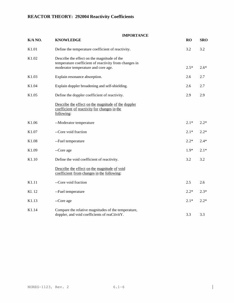
NUREG-1123, Rev. 2 |6.1-6
REACTOR THEORY: 292004 Reactivity Coefficients
IMPORTANCE K/A NO. KNOWLEDGE RO SRO
K1.01 Define the temperature coefficient of reactivity. 3.2 3.2
K1.02 Describe the effect on the magnitude of thetemperature coefficient of reactivity from changes inmoderator temperature and core age. 2.5* 2.6*
K1.03 Explain resonance absorption. 2.6 2.7
K1.04 Explain doppler broadening and self-shielding. 2.6 2.7
K1.05 Define the doppler coefficient of reactivity. 2.9 2.9
Describe the effect on the magnitude of the doppler coefficient of reactivity for changes in the following:
K1.06 --Moderator temperature 2.1* 2.2*
K1.07 --Core void fraction 2.1* 2.2*
K1.08 --Fuel temperature 2.2* 2.4*
K1.09 --Core age 1.9* 2.1*
K1.10 Define the void coefficient of reactivity. 3.2 3.2
Describe the effect on the magnitude of void coefficient from changes in the following:
K1.11 --Core void fraction 2.5 2.6
Kl. 12 --Fuel temperature 2.2* 2.3*
K1.13 --Core age 2.1* 2.2*
K1.14 Compare the relative magnitudes of the temperature,doppler, and void coefficients of reaCtivitY. 3.3 3.3

NUREG-1123, Rev. 2 |6.1-7
REACTOR THEORY: 292005 Control Rods
IMPORTANCE K/A NO. KNOWLEDGE RO SRO
K1.01 Relate notch and rod position. 3.2* 3.3*
K1.02 Name the material used for thermal neutron absorptionin control rods. 2.5 2.6
K1.03 Describe nuclear properties of active material in therod. 1.9* 1.9*
K1.04 Predict direction of change in reactor power for achange in control rod position. 3.5 3.5
K1.05 Define rod density. 2.5* 2.6
K1.06 Define reactor scram. 3.7* 3.8*
K1.07 Define control rod worth, differential control rodworth, and integral control rod worth. 2.4 2.6
K1.08 Explain the shape of curves for differential andintegral CRW versus rod position. 2.1* 2.3
K1.09 Explain direction of change in the magnitude of CRWfor a change in moderator temperature, void fraction,and control rod density, and Xenon. 2.5* 2.6
K1.10 †State the purpose of flux shaping and rod sequencing. 2.8 3.3
K1.11 Define deep rods, and shallow rods. 2.4* 2.5*
K1.12 †Describe effects of deep, and shallow control rods on axial and radial flux distribution. 2.6 2.9

NUREG-1123, Rev. 2 |6.1-8
REACTOR THEORY: 292006 Fission Product Poisons
IMPORTANCE K/A NO. KNOWLEDGE RO SRO
K1.01 Define fission product poison. 2.7 2.8
K1.02 State the characteristics of Xenon-135 as a fissionproduct poison. 3.1 3.1
K1.03 Describe the production of Xenon-135. 2.9 2.9
K1.04 Describe the removal of Xenon-135. 2.9 2.9
Describe the following processes and state their effect on reactor operations:
K1.05 --Equilibrium Xenon 2.9 2.9
K1.06 --Maneuvering Xenon 2.7 2.7
K1.07 --Xenon following a scram 3.2 3.2
K1.08 †Describe the effects that Xenon concentration has onflux shape and control rod patterns. 2.8 3.2
Plot the curve and explain the reasoning for the reactivity insertion by Xenon-135 versus time for the following:
K1.09 --Initial reactor startup and ascension to ratedpower. 2.5 2.5
K1.10 --Reactor startup with Xenon-135 already present inthe core 2.9 2.9
K1.11 --Power changes from steady-state power to another. 2.6 2.7
K1.12 --Reactor scram. 2.8 2.3
K1.13 --Reactor shutdown. 2.6* 2.6
K1.14 Explain the process and reasons for the ReactorOperator to compensate for the time dependent behaviorof Xenon-135 concentration in the reactor. 3.1 3.2
K1.15 State the characteristics of Samarium-149 as a fissionproduct poison. 2.1* 2.1*|
K1.16 Describe the production of Samarium-149. 1.8* 1.9*
K1.17 Describe the removal of Samarium-149. 1.9* 1.9*

NUREG-1123, Rev. 2 |6.1-9
REACTOR THEORY: 292006 Fission Product Poisons
IMPORTANCE K/A NO. KNOWLEDGE RO SRO
K1.18 Define equilibrium samarium. 1.8* 1.8*
Plot the curve and explain the reasoning for reactivity insertion by Samarium-149 versus time for the following:
K1.19 --Initial reactor startup and ascension to ratedpower. 1.7* 1.8*
K1.20 --Reactor shutdown. 1.6* 1.7*
K1.21 Describe effects of power changes on samariumconcentration. 1.7* 1.8*
K1.22 Compare effects of Samarium-149 on reactor operationwith those of Xenon-135. 2.4* 2.4

NUREG-1123, Rev. 2 |6.1-10
REACTOR THEORY: 292007 Fuel Depletion And Burnable Poisons
IMPORTANCE K/A NO. KNOWLEDGE RO SRO
K1.01 Define burnable poison and state its use in thereactor. 2.9 3.1
K1.02 Describe and explain distribution of burnable poisonsin the core. 1.8* 2.0*
K1.03 †Given a curve of K-effective versus core age, statethe reasons for maximum, minimum, and inflectionpoints. 2.4* 2.7

NUREG-1123, Rev. 2 |6.1-11
REACTOR THEORY: 292008 Reactor Operational Physics
IMPORTANCE K/A NO. KNOWLEDGE RO SRO
Startup and Approach to Criticality
K1.01 List parameters which should be monitored andcontrolled during the approach to criticality. 3.8 3.9*
K1.02 List reactivity control mechanisms which exist forplant conditions during the approach to criticality. 3.8 3.8
K1.03 Describe count rate and period response which shouldbe observed for rod withdrawal during the approach tocriticality. 4.1 4.0
K1.04 Relate the concept of subcritical multiplication topredicted count rate and period response for controlrod withdrawal during the approach to critical. 3.3 3.4
K1.05 Explain characteristics to be observed when thereactor is very close to criticality. 4.3* 4.3*
Criticality
K1.06 List parameters which should be monitored andcontrolled upon reaching initial criticality. 4.2* 4.2
K1.07 Define criticality as related to a reactor startup. 3.9 3.9
K1.08 Describe reactor power and period response oncecriticality is reached. 4.1 4.1
Intermediate Range Operation
K1.09 List parameters which should be monitored andcontrolled during the intermediate phase of startup. 3.9* 3.9*
K1.10 Explain procedures for adjusting reactor period duringthe intermediate phase of startup. 3.6 3.6
K1.11 Discuss the concept of the point of adding heat (POAH)and its impact on reactor power. 3.7 3.8
K1.12 Describe reactor power and period response prior toreaching the POAH. 3.6 3.7
K1.13 Explain characteristics to look for when the POAH isreached. 3.8 3.9

NUREG-1123, Rev. 2 |6.1-12
REACTOR THEORY: 292008 Reactor Operational Physics
IMPORTANCE K/A NO. KNOWLEDGE RO SRO
Heatup Operation
K1.14 Describe three parameters to be monitored andcontrolled during heatup. 3.5 3.5
K1.15 Describe reactor power and period response afterreaching the point of adding heat. 3.7 3.7
K1.16 Explain procedures for establishing and controllingheatup rate. 3.6 3.7
Power Operation
K1.17 Describe three parameters to be monitored andcontrolled during power operation. 3.6 3.6
K1.18 Describe means by which reactor power will beincreased to rated power. 3.8 3.8
K1.19 Explain transient and steady-state effects of acontrol rod withdrawal on reactor power and voidfraction content. 3.1 3.2
K1.20 Explain transient and steady-state effects of anincrease in core flow on reactor power and voidfraction. 3.3 3.4
K1.21 Explain the relationship between steam production rateand reactor power given specific conditions. 2.9 3.0
K1.22 Explain the effect that opening steam bypass valves,during power operation, will have on reactor power. 3.5 3.6
K1.23 †Explain the necessity for rod pattern exchanges. 2.6 3.1
K1.24 †Describe the parameters to be monitored and controlledduring rod pattern exchanges. 2.8 3.2
Reactor Response on a Scram
K1.25 Explain the shape of a curve of reactor power versustime after a scram. 2.8 2.9
Normal Reactor Shutdown
K1.26 Explain reactor power response to a decrease in coreflow. 3.4 3.7
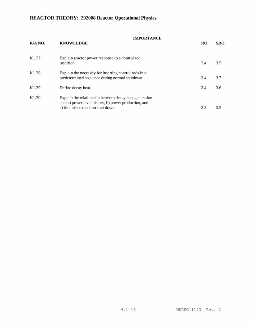
NUREG-1123, Rev. 2 |6.1-13
REACTOR THEORY: 292008 Reactor Operational Physics
IMPORTANCE K/A NO. KNOWLEDGE RO SRO
K1.27 Explain reactor power response to a control rodinsertion. 3.4 3.5
K1.28 Explain the necessity for inserting control rods in apredetermined sequence during normal shutdown. 3.4 3.7
K1.29 Define decay heat. 3.4 3.6
K1.30 Explain the relationship between decay heat generationand: a) power level history, b) power production, andc) time since reaction shut down. 3.2 3.5

NUREG-1123, Rev. 2 |6.1-14
This page left blank

NUREG-1123, Rev. 2 |6.2-1
6.2 THERMODYNAMICS(CFR: 41.14)
THERMODYNAMICS: 293001 Thermodynamic Units and Properties
IMPORTANCE K/A NO. KNOWLEDGE RO SRO
K1.01 Convert between absolute and relative pressure andvacuum scales. 2.2* 2.3*
K1.02 Recognize the difference between absolute and relativetemperature scales. 2.1* 2.1*
K1.03 Describe how common pressure and level sensinginstruments work. 2.5* 2.7
K1.04 Explain relationships between work, power, and energy. 1.8* 1.9*

NUREG-1123, Rev. 2 |6.2-2
THERMODYNAMICS: 293002 Basic Energy Concepts
IMPORTANCE K/A NO. KNOWLEDGE RO SRO
K1.01 Identify energy and work forms. 1.6* 1.7*
K1.02 Explain the law of conservation of energy. 1.9* 1.9*
K1.03 Explain the difference between state and phase of aworking substance. 1.6* 1.7*
K1.04 Explain the application of enthalpy in the monitoringof plant processes. 2.1* 2.4*
K1.05 Identify the relationship between heat flow during aprocess and a T-s diagram representation of theprocess. 2.0* 2.2*
K1.06 Define specific heat. 1.8* 2.1*
K1.07 Apply specific heat in solving heat transfer problems. 1.5* 1.6*
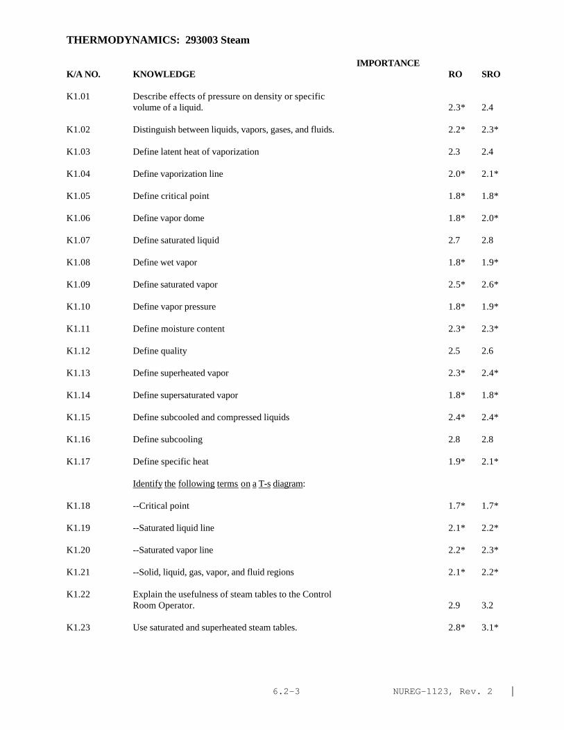
NUREG-1123, Rev. 2 |6.2-3
THERMODYNAMICS: 293003 Steam
IMPORTANCE K/A NO. KNOWLEDGE RO SRO
K1.01 Describe effects of pressure on density or specificvolume of a liquid. 2.3* 2.4
K1.02 Distinguish between liquids, vapors, gases, and fluids. 2.2* 2.3*
K1.03 Define latent heat of vaporization 2.3 2.4
K1.04 Define vaporization line 2.0* 2.1*
K1.05 Define critical point 1.8* 1.8*
K1.06 Define vapor dome 1.8* 2.0*
K1.07 Define saturated liquid 2.7 2.8
K1.08 Define wet vapor 1.8* 1.9*
K1.09 Define saturated vapor 2.5* 2.6*
K1.10 Define vapor pressure 1.8* 1.9*
K1.11 Define moisture content 2.3* 2.3*
K1.12 Define quality 2.5 2.6
K1.13 Define superheated vapor 2.3* 2.4*
K1.14 Define supersaturated vapor 1.8* 1.8*
K1.15 Define subcooled and compressed liquids 2.4* 2.4*
K1.16 Define subcooling 2.8 2.8
K1.17 Define specific heat 1.9* 2.1*
Identify the following terms on a T-s diagram:
K1.18 --Critical point 1.7* 1.7*
K1.19 --Saturated liquid line 2.1* 2.2*
K1.20 --Saturated vapor line 2.2* 2.3*
K1.21 --Solid, liquid, gas, vapor, and fluid regions 2.1* 2.2*
K1.22 Explain the usefulness of steam tables to the ControlRoom Operator. 2.9 3.2
K1.23 Use saturated and superheated steam tables. 2.8* 3.1*
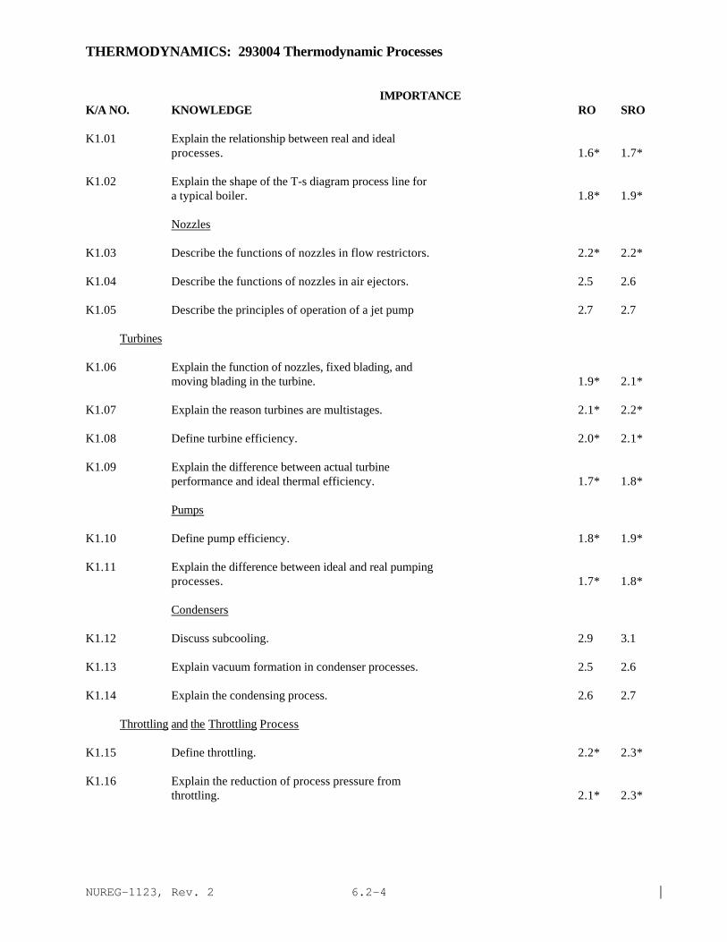
NUREG-1123, Rev. 2 |6.2-4
THERMODYNAMICS: 293004 Thermodynamic Processes
IMPORTANCE K/A NO. KNOWLEDGE RO SRO
K1.01 Explain the relationship between real and idealprocesses. 1.6* 1.7*
K1.02 Explain the shape of the T-s diagram process line fora typical boiler. 1.8* 1.9*
Nozzles
K1.03 Describe the functions of nozzles in flow restrictors. 2.2* 2.2*
K1.04 Describe the functions of nozzles in air ejectors. 2.5 2.6
K1.05 Describe the principles of operation of a jet pump 2.7 2.7
Turbines
K1.06 Explain the function of nozzles, fixed blading, andmoving blading in the turbine. 1.9* 2.1*
K1.07 Explain the reason turbines are multistages. 2.1* 2.2*
K1.08 Define turbine efficiency. 2.0* 2.1*
K1.09 Explain the difference between actual turbineperformance and ideal thermal efficiency. 1.7* 1.8*
Pumps
K1.10 Define pump efficiency. 1.8* 1.9*
K1.11 Explain the difference between ideal and real pumpingprocesses. 1.7* 1.8*
Condensers
K1.12 Discuss subcooling. 2.9 3.1
K1.13 Explain vacuum formation in condenser processes. 2.5 2.6
K1.14 Explain the condensing process. 2.6 2.7
Throttling and the Throttling Process
K1.15 Define throttling. 2.2* 2.3*
K1.16 Explain the reduction of process pressure fromthrottling. 2.1* 2.3*

NUREG-1123, Rev. 2 |6.2-5
THERMODYNAMICS: 293005 Thermodynamic Cycles
IMPORTANCE K/A NO. KNOWLEDGE RO SRO
K1.01 Define thermodynamic cycle. 1.7* 1.8*
K1.02 Define thermodynamic cycle efficiency in terms of network produced and energy applied. 1.7* 1.7*
Kl.03 Describe the moisture effects on turbine integrity andefficiency. 2.6 2.7
K1.04 Explain steam quality effects on nuclear turbinedesign. 2.3* 2.4*
K1.05 State the advantages of moisture separators/reheatersand feedwater heaters for a typical steam cycle. 2.7 2.8

NUREG-1123, Rev. 2 |6.2-6
THERMODYNAMICS: 293006 Fluid Statics
IMPORTANCE K/A NO. KNOWLEDGE RO SRO
K1.01 Distinguish between fluids and other substances. 1.7* 1.8*
K1.02 Distinguish between static pressure, dynamic pressure,and total pressure. 2.0* 2.2*
K1.03 Define head loss. 2.4 2.5
K1.04 Discuss operational considerations of viscosity asrelated to head loss. 1.7* 1.9*
K1.05 Explain operational implications of fluid hammer 3.2 3.3
Pumps and Pump Characteristics
K1.06 --State the purpose of a pump. 2.5* 2.6*
K1.07 --Discuss pump head. 2.5 2.6
K1.08 --Discuss relationship between pump speed, head, flow,and power without using formulas or calculations. 2.5 2.6
K1.09 --Define cavitation. 2.8 2.9
K1.10 --Define net positive suction head (NPSH). 2.7 2.8
K1.11 --Define pump shut-off head, pump runout, and axialthrust. 2.4 2.5
K1.12 --Explain the importance of proper system venting forpump operations. 2.9 2.9
K1.13 --Explain the results of putting centrifugal pumps inparallel or series combinations. 2.6 2.7
K1.14 --Given the characteristic curve for a typicalcentrifugal pump, explain the reason for its shape. 2.2* 2.3*
K1.15 --Using a centrifugal pump characteristic curve and asystem characteristic curve, illustrate how the systemoperating point changes due to system changes. 2.3* 2.4*
K1.16 --Describe how a centrifugal pump characteristic curvewill change with pump speed. 2.1* 2.3*
K1.17 --Explain how operating a centrifugal pump at shutoffhead may cause overheating of the pump and describemethods used to avoid overheating. 2.6 2.7

NUREG-1123, Rev. 2 |6.2-7
THERMODYNAMICS: 293006 Fluid Statics
IMPORTANCE K/A NO. KNOWLEDGE RO SRO
K1.18 --Discuss the characteristic curve for a typicalpositive displacement pump and explain the reason forits shape. 1.9* 2.1*
K1.19 --Describe the problems that will occur in emergencycore cooling systems if the pumps are operated atlower than design flow for extended periods of time. 2.7 2.9
K1.20 Define or explain mass flow rate 2.4 2.4
K1.21 Define or explain two-phase flow 2.4* 2.6
K1.22 Define or explain pressure spike 2.2* 2.3*
K1.23 Define or explain gas binding 2.2* 2.3*
K1.24 Define or explain recirculation ratio 2.1* 2.3*
K1.25 Define or explain pipe whip 2.1* 2.2*
K1.26 Explain why flow measurements must be corrected fordensity changes. 2.3 2.4
K1.27 Explain the relationship between pressure head andvelocity head in a fluid system. 1.8* 2.0*
K1.28 Discuss the velocity profiles for laminar flow andtubulent flow. 1.7* 1.8*
K1.29 Describe the methods of controlling system flow rates. 2.6 2.7

NUREG-1123, Rev. 2 |6.2-8
THERMODYNAMICS: 293007 Heat Transfer and Heat Exchanges
IMPORTANCE K/A NO. KNOWLEDGE RO SRO
Heat Transfer
K1.01 Describe three mechanisms of heat transfer. 3.2 3.2
K1.02 Describe thermal conductivity. 2.4 2.6
K1.03 Explain the manner in which fluid films affects heattransfer. 2.7 2.8
Heat Exchangers
K1.04 Discuss parallel-flow heat exchangers. 1.9* 2.2*
K1.05 Discuss counter-flow heat exchangers. 2.0* 2.2*
K1.06 Discuss the factors which affect heat transfer rate ina heat exchanger. 2.7 2.8
K1.07 Describe how the presence of gases or steam can affectheat transfer and fluid flow in heat exchangers. 2.7 2.9
Condenser Applications of Heat Transfer
K1.08 List functions of the main condenser in a power plant. 3.0 3.1
K1.09 Discuss operational implications of condensatedepression. 2.5 2.7
Core Thermal Power
K1.10 Define core thermal power. 2.7* 2.9*
K1.11 †Explain methods of calculating core thermal power. 2.6 3.1
K1.12 Define percent reactor power. 2.6* 2.7*
K1.13 †Calculate core thermal power using a simplified heatbalance. 2.3* 2.9*
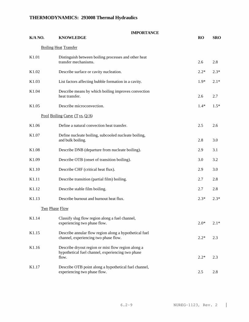
NUREG-1123, Rev. 2 |6.2-9
THERMODYNAMICS: 293008 Thermal Hydraulics
IMPORTANCE K/A NO. KNOWLEDGE RO SRO
Boiling Heat Transfer
K1.01 Distinguish between boiling processes and other heattransfer mechanisms. 2.6 2.8
K1.02 Describe surface or cavity nucleation. 2.2* 2.3*
K1.03 List factors affecting bubble formation in a cavity. 1.9* 2.1*
K1.04 Describe means by which boiling improves convectionheat transfer. 2.6 2.7
K1.05 Describe microconvection. 1.4* 1.5*
Pool Boiling Curve (T vs. Q/A)
K1.06 Define a natural convection heat transfer. 2.5 2.6
K1.07 Define nucleate boiling, subcooled nucleate boiling,and bulk boiling. 2.8 3.0
K1.08 Describe DNB (departure from nucleate boiling). 2.9 3.1
K1.09 Describe OTB (onset of transition boiling). 3.0 3.2
K1.10 Describe CHF (critical heat flux). 2.9 3.0
K1.11 Describe transition (partial film) boiling. 2.7 2.8
K1.12 Describe stable film boiling. 2.7 2.8
K1.13 Describe burnout and burnout heat flux. 2.3* 2.3*
Two Phase Flow
K1.14 Classify slug flow region along a fuel channel,experiencing two phase flow. 2.0* 2.1*
K1.15 Describe annular flow region along a hypothetical fuelchannel, experiencing two phase flow. 2.2* 2.3
K1.16 Describe dryout region or mist flow region along ahypothetical fuel channel, experiencing two phaseflow. 2.2* 2.3
K1.17 Describe OTB point along a hypothetical fuel channel,experiencing two phase flow. 2.5 2.8

NUREG-1123, Rev. 2 |6.2-10
THERMODYNAMICS: 293008 Thermal Hydraulics
IMPORTANCE K/A NO. KNOWLEDGE RO SRO
K1.18 Describe effects of flowrate and phase change on theheat transfer coefficient. 2.2* 2.4
Core Inlet Subcooling
K1.19 Define core inlet subcooling. 2.6 2.8
K1.20 Define carryunder. 2.4 2.6
Voids and Void Fraction
K1.21 Define void fraction. 3.0 3.0
K1.22 Explain the term void as applied to core operations 2.9 3.0
K1.23 Define qualilty 2.5 2.7
K1.24 Draw the temperature profile from the centerline of afuel pellet to the centerline of the channel. 2.4 2.5
Recirculation System
K1.25 Explain the reason for forced core recirculation. 3.2 3.2
K1.26 Explain the jet pump operating principle. 2.9 3.1
K1.27 Explain the necessity of determining core coolantflow. 2.9 3.0
K1.28 Describe the factors affecting single- and two-phaseflow resistance. 2.3* 2.5*
Core Orificing
K1.29 Describe the effects of increasing bundle power onbundle flow resistance. 2.8 3.0
K1.30 Compare the flow resistance through high poweredbundles to that of low powered bundles. 2.7 2.7
K1.31 Explain the necessity of core orificing. 2.9 3.0
K1.32 Describe core bypass flow. 2.5 2.6
K1.33 Explain the need for adequate core bypass flow.
Natural Circulation 2.4 2.6

NUREG-1123, Rev. 2 |6.2-11
THERMODYNAMICS: 293008 Thermal Hydraulics
IMPORTANCE K/A NO. KNOWLEDGE RO SRO
K1.34 Explain the causes of natural circulation in BWR's. 2.9 3.1
K1.35 Describe problems that thermal stratification cancause. 3.1 3.3
K1.36 Describe means by which the operator can determine ifnatural circulation flow exists. 3.1 3.3
K1.37 Describe means by which the operator can enhancenatural circulation. 3.2 3.4
Sketch the axial temperature and enthalpy profiles fora typical reactor coolant channel and describe howthey are affected by the following:
K1.38 --Onset of nucleate boiling 1.8* 2.1*
K1.39 --Axial core flux 1.8* 1.9*
K1.40 --Inlet temperature 1.8* 1.9*
K1.41 --Heat generation rate 1.8* 2.0*
K1.42 --Flow rate in the channel 1.8* 1.9*
K1.43 Sketch the temperature profile in the axial and radialdirections for a typical fuel rod and explain thereason for its shape. 2.0* 2.2*
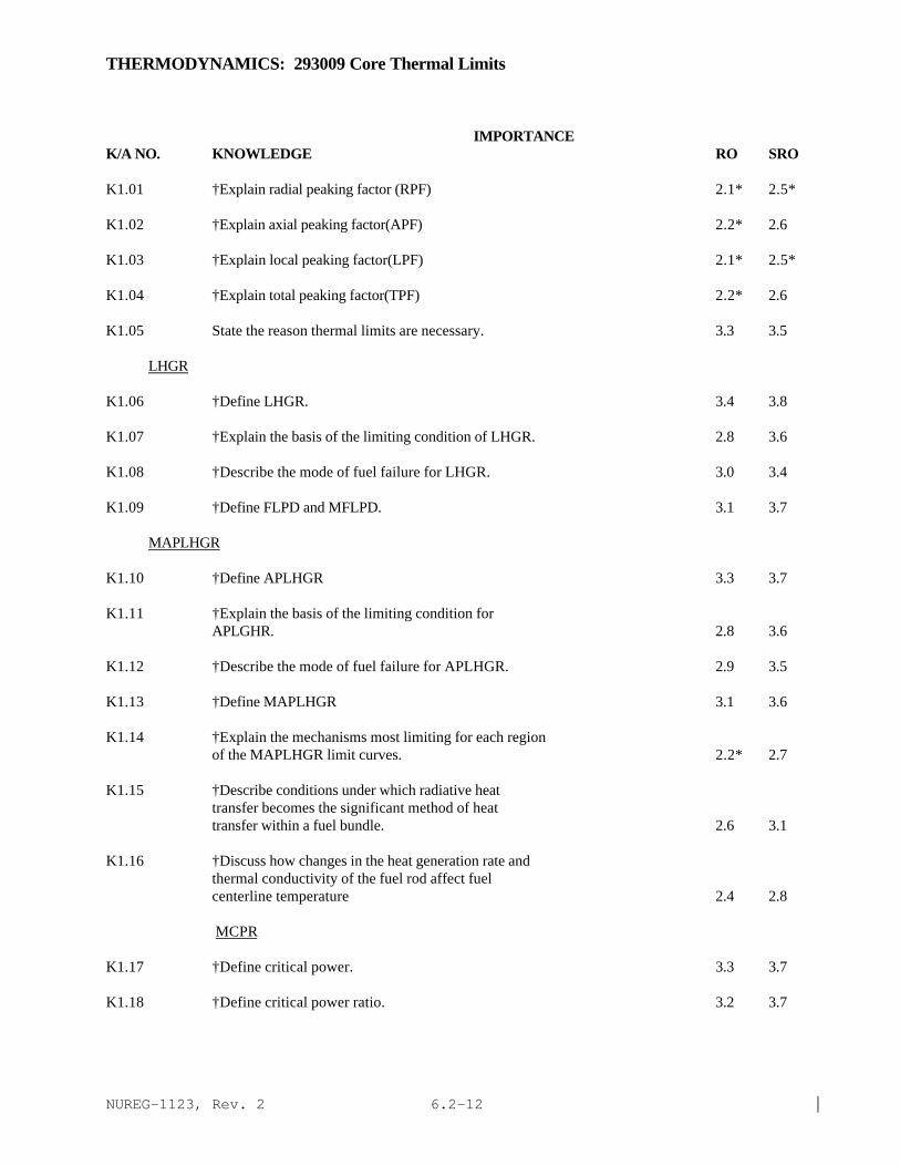
NUREG-1123, Rev. 2 |6.2-12
THERMODYNAMICS: 293009 Core Thermal Limits
IMPORTANCE K/A NO. KNOWLEDGE RO SRO
K1.01 †Explain radial peaking factor (RPF) 2.1* 2.5*
K1.02 †Explain axial peaking factor(APF) 2.2* 2.6
K1.03 †Explain local peaking factor(LPF) 2.1* 2.5*
K1.04 †Explain total peaking factor(TPF) 2.2* 2.6
K1.05 State the reason thermal limits are necessary. 3.3 3.5
LHGR
K1.06 †Define LHGR. 3.4 3.8
K1.07 †Explain the basis of the limiting condition of LHGR. 2.8 3.6
K1.08 †Describe the mode of fuel failure for LHGR. 3.0 3.4
K1.09 †Define FLPD and MFLPD. 3.1 3.7
MAPLHGR
K1.10 †Define APLHGR 3.3 3.7
K1.11 †Explain the basis of the limiting condition forAPLGHR. 2.8 3.6
K1.12 †Describe the mode of fuel failure for APLHGR. 2.9 3.5
K1.13 †Define MAPLHGR 3.1 3.6
K1.14 †Explain the mechanisms most limiting for each regionof the MAPLHGR limit curves. 2.2* 2.7
K1.15 †Describe conditions under which radiative heattransfer becomes the significant method of heattransfer within a fuel bundle. 2.6 3.1
K1.16 †Discuss how changes in the heat generation rate andthermal conductivity of the fuel rod affect fuelcenterline temperature 2.4 2.8
MCPR
K1.17 †Define critical power. 3.3 3.7
K1.18 †Define critical power ratio. 3.2 3.7

NUREG-1123, Rev. 2 |6.2-13
THERMODYNAMICS: 293009 Core Thermal Limits
IMPORTANCE K/A NO. KNOWLEDGE RO SRO
K1.19 †Explain the basis of the limiting condition for CPR. 2.8 3.6
K1.20 †Describe the mode of fuel failure for CPR. 3.1 3.6
K1.21 †Define MCPR. 3.1 3.6
K1.22 †Describe the effects of subcooling on critical power. 2.9 3.3
K1.23 †Describe the effects of mass flow on critical power. 2.8 3.2
K1.24 †Describe the effects of pressure on critical power. 2.7 3.2
K1.25 †Describe the effects of local power distribution on critical power. 2.7 3.2
K1.26 †Describe the effects of axial power distribution on critical power. 2.6 3.1
K1.27 †Explain the purpose of the flow biasing correlation factor, (K ), as it relates to MCPR limits. 2.7 3.3
K1.28 †Define FLCPR. 3.0 3.5
Thermal Time Constant
K1.29 Define fuel thermal time constant. 2.4* 2.7
K1.30 †Relate thermal time constant to transient operating condition. 2.3 2.7
Pellet Clad Interaction
K1.31 Describe pellet-clad interaction (PCI). 3.0 3.4
K1.32 List the causes of PCI. 2.9 3.3
K1.33 Describe the purpose of the pellet to clad gap. 2.4 2.8
K1.34 Identify the possible effects of fuel densification. 2.3* 2.6
K1.35 Describe the effects of iodine and cadmium on PCI. 2.2* 2.6*
PCIOMR
K1.36 †Explain the purpose for PCIOMR (Plant Specific). 2.8 3.4
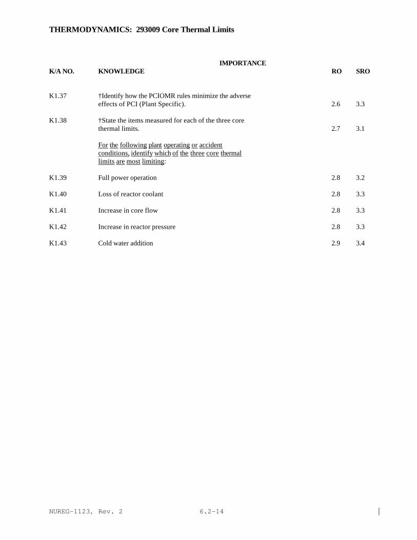
NUREG-1123, Rev. 2 |6.2-14
THERMODYNAMICS: 293009 Core Thermal Limits
IMPORTANCE K/A NO. KNOWLEDGE RO SRO
K1.37 †Identify how the PCIOMR rules minimize the adverseeffects of PCI (Plant Specific). 2.6 3.3
K1.38 †State the items measured for each of the three corethermal limits. 2.7 3.1
For the following plant operating or accidentconditions, identify which of the three core thermallimits are most limiting:
K1.39 Full power operation 2.8 3.2
K1.40 Loss of reactor coolant 2.8 3.3
K1.41 Increase in core flow 2.8 3.3
K1.42 Increase in reactor pressure 2.8 3.3
K1.43 Cold water addition 2.9 3.4

NUREG-1123, Rev. 2 |6.2-15
THERMODYNAMICS: 293010 Brittle Fracture and Vessel Thermal Stress
IMPORTANCE K/A NO. KNOWLEDGE RO SRO
K1.01 State the brittle fracture mode of failure. 2.4* 2.8
K1.02 †State the definition of Nil-Ductility TransitionTemperature. 2.2* 2.7
K1.03 Define reference temperature. 2.0* 2.5
K1.04 †State how the possibility of brittle fracture isminimized by operating limitations. 2.9 3.2
K1.05 †State the effect of fast neutron irradiation onreactor vessel metals. 2.5 2.8

NUREG-1123, Rev. 2 |6.2-16
This page left blank