Embed Size (px)
Citation preview

246 247
Sp
urG
ears
Hel
ical
Gea
rsIn
tern
alG
ears
Rac
ksC
P R
acks
& P
inio
nsM
iter
Gea
rsB
evel
Gea
rsS
crew
Gea
rsW
orm
Gea
r P
airs
Bev
elG
earb
oxes
Oth
erP
rod
ucts
Sp
urG
ears
Hel
ical
Gea
rsIn
tern
alG
ears
Rac
ksC
P R
acks
& P
inio
nsM
iter
Gea
rsB
evel
Gea
rsS
crew
Gea
rsW
orm
Gea
r P
airs
Bev
elG
earb
oxes
Oth
erP
rod
ucts
Catalog NumberPitch mm
(Module)No. of teeth
ShapeTotal Length Face width Height Height to pitch line Allowable force (N) Allowable force (kgf) Weight
(kg)A B C D Bending strength Surface durability Bending strength Surface durability
KMRGCPF5-500 CP5 (1.5915) 100RF 500
15 20 18.41 5380 5000 548 509 1.08
KMRGCPF10-500 CP10 (3.1831) 50 30 35 31.82 21500 20100 2190 2050 3.75
CP Hardened Ground RacksCircular pitch 5, 10KMRGCPF/KMRGCPFD
Specifications
Precision grade KHK R 001 Grade 1 *
Gear teeth Standard full depth
Pressure angle 20°
Material SCM415
Heat Treatment Tooth area carburized
Tooth hardness 55 to 60HRC
BCD
A
CP CPG G
G
G G
RF
Catalog Number● : J Series (Available-on-request)
Pitch mm
(Module)No. of teeth
ShapeTotal Length Face width Height Height to pitch line Mounting hole dimensions
A B C D E F G No. of holes Screw size
CP5 (1.5915) 100RD 500
15 20 18.41 825 150 4
M5• KMRGCPFD5-500J• KMRGCPFD10-500J CP10 (3.1831) 50 30 35 31.82 14 M10
[Caution on Product Characteristics] ① The allowable forces shown in the table are calculated values according to the assumed usage conditions. Please see Page 241 for more details.② The backlash of racks differs depending on the size of the mating pinion. Calculate the backlash from the backlash value of the
mating pinion. Also, please refer to the data in the section called ‘Backlash of Rack Teeth (Amount of Tooth Thinning)’ on Page 193.[Caution on Secondary Operations] ① Please read "Cautions on Performing Secondary Operations" (Page 242) when performing modifications and/or secondary operations
for safety concerns. ② In the illustration, the area surrounded with line is masked during the carburization process and can be modified. However,
the end faces on both sides do not have an anti-carburization coating on the taped holes, as otherwise they could not be machined.
* The precision grade of J Series products is equivalent to the value shown in the table.
CP Ground Spur GearsCircular pitch 5, 10KMSCPG
A B C D
GE F
G
G G
G
J
S1K
Catalog NumberPitch mm
(Module)No. of teeth
Dislocation coefficient
Mounting distance
ShapeBore Hub dia. Pitch dia. Outside dia. Face width Hub width Total Length
AH7 B C D E F G
KMSCPG5-20AKMSCPG5-20B
CP5 (1.5915)
20 +0.425 35
S1K
1215 28 31.83 36.37
15 15 30
KMSCPG5-25AKMSCPG5-25B 25 +0.438 39 12
15 35 39.79 44.37
KMSCPG5-30AKMSCPG5-30B 30 +0.451 43 15
20 40 47.75 52.37
KMSCPG5-40AKMSCPG5-40BKMSCPG5-40C
40 +0.478 51152025
45 63.66 68.37
KMSCPG10-20AKMSCPG10-20B
CP10 (3.1831)
20 +0.111 64
S1K
2025 50 63.66 70.73
30 20 50
KMSCPG10-25AKMSCPG10-25B 25 +0.124 72 25
30 60 79.58 86.73
KMSCPG10-30AKMSCPG10-30B 30 +0.137 80 30
40 70 95.49 102.73
KMSCPG10-40AKMSCPG10-40B 40 +0.164 96 30
40 70 127.32 134.73
[Caution on Product Characteristics] ① Although the dimensions of the keyway are made to the JIS B1301 (Js9) tolerance, there may be some deviations due to the effects of the heat treatment.② The allowable torques shown in the table are calculated values according to the assumed usage conditions. Please see Page 241 for more details.③ The backlash values shown in the table are the theoretical values (the above mounting distance) when these gears and KMRGCPF Racks are in
mesh. When joining with other products, calculate the mounting distance using the profile shifted gear formula. Please see Page 18 of our technical reference book for more details.
Specifications
Precision grade JIS grade N5 (JIS B1702-1: 1998)
Gear teeth Standard full depth
Pressure angle 20°
Material SCM415
Heat Treatment Carburized
Tooth hardness 55 to 60HRC
Ground RacksCP
KMRGCPF/KMRGCPFD
A
C
BG GGF (F)H
EDI J
CP CPG G
G
G G
RD
Counterbore dimensions Allowable force (N) Allowable force (kgf) Weight
(kg)Catalog Number
● : J Series (Available-on-request)H I J Bending strength Surface durability Bending strength Surface durability
6 10 6 5380 5000 548 509 1.06
10.8 17.5 11 21500 20100 2190 2050 3.61
•KMRGCPFD5-500J
•KMRGCPFD10-500J
[Caution on J series]
Surface durability is 4 times higher than KSRGCP Hardened Ground Racks, 2 times higher than KKRGCP-H Hardened Ground Racks.
① As available-on-request products, these require a lead-time for shipping within 2 working days (excludes the day ordered), after placing an order.Please allow additional shipping time to get to your local distributor.
② Number of products we can process for one order is 1 to 20 units. For quantitiesof 21 or more pieces, we need to quote price and lead time.
Ground Spur GearsCP
Keyway Socket head screw Distance traveled in one turn
(mm)
Allowable torque (N·m) Allowable torque (kgf·m) Backlash
(mm)
Weight
(kg)Catalog Number
Width × Depth Size J Bending strength Surface durability Bending strength Surface durability
4x 1.85x 2.3 M4
7.5
100 70.0 46.7 7.13 4.76
0.04-0.13
0.140.13
KMSCPG5-20AKMSCPG5-20B
4x 1.85x 2.3 M4 125 91.8 78.2 9.37 7.97 0.24
0.22KMSCPG5-25AKMSCPG5-25B
5x 2.36x 2.8
M4M5 150 114 119 11.6 12.2 0.32
0.29KMSCPG5-30AKMSCPG5-30B
5x 2.36x 2.88x 3.3
M4M5M6
200 159 229 16.2 23.40.530.500.45
KMSCPG5-40AKMSCPG5-40BKMSCPG5-40C
6x 2.88x 3.3
M5M6
10
200 514 375 52.4 38.2
0.06-0.16
0.940.87
KMSCPG10-20AKMSCPG10-20B
8x 3.3 M6 250 689 628 70.3 64.1 1.431.34
KMSCPG10-25AKMSCPG10-25B
8x 3.312x 3.3
M6M8 300 868 960 88.5 97.9 2.03
1.80KMSCPG10-30AKMSCPG10-30B
8x 3.312x 3.3
M6M8 400 1230 1850 126 188 3.36
3.13KMSCPG10-40AKMSCPG10-40B
[Caution on Secondary Operations] ① No secondary operations can be performed on these precision finished gears due to the applied carburizing process.For products which are different in specifications, such as bore size, we accept custom-made gear orders and provide a price quote.
KMSCPG
Mounting distance of a profile shifted gear and the meshing rack
Mou
ntin
g di
stan
ce
Hei
ght t
o pi
tch
line
Series

Surface hardening comes as standard.The surface durability is increased about 4 times with Hardened Plus.Ideal as a mating pinion for hardened racks (H Series) and laser hardened racks (HL Series).Use to improve the durability of gears.
New ProductNew Product
Hardened Plus Induction hardening specification
● Quick delivery, hardening completed in 4 workingdaysGear tooth induction hardening is completed in 4 workingdays excluding the day the order is placed.
● The surface durability is increased about 4 timesThe surface durability is increased about 4 times.
● Product unit price + hardening unit priceThe hardening unit price is added to the product unit price.For details, please see the table below.
Hardening is provided additionally to standard products when ordered.Products with at the end of the Catalog No. support Hardened Plus.
Note 1: The surface durability values shown in the table are calcu-lated values according to the assumed usage conditions. Please calculate the actual surface durability in the KHK Web Catalog.
Note 2: The gear precision decreases by about one grade after hard-ening. The bore dimension tolerance H7 will also be ungraded.
Note 3: Black oxide processing cannot be performed again after hardening.
Area: Tooth surface hardening
Hardness: HRC50 to 60
Depth: 1 mm or more
The hardening method and the state of the hardened teeth area vary depending on the size of gears.
The hardening depth is where the Vickers hardness from the tooth surface to the deep area is up to HV450 (from JIS G 0559: 2008).Note that hardening specifications of Hardening Plus above will be near the standard pitch diameter of the gear.
● Hardness and depth of gear-teeth induction hardening
Hardened Plus compatible products
KSS/KSSA/KSSCP Spur Gears
KKS/KKSSCP Thermal Refined Spur Gears
Spur Gears
Image Diagram
Catalog No. + His the order method.
Example: Catalog No.: KSS3-20, when hardening is added
⇒ KSS3-20H
20

192 193
The precision standards of KHK stock racks are established by us.The table below indicates the tolerance ranges of our racks.
3. Cautions on Selecting Racks By Precision
■ Precision Grades of Racks (KHK R 001) Unit: μm
Grade
Pitch E
rror
Over m0.4 to 1CP2.5
Over m1 to 1.6CP5
Over m1.6 to 2.5-
Over m2.5 to 4CP10
Over m4 to 6CP15
Over m6 to 10CP20
Rack Length (nominal)
1000 or less
1001 up to 2000
1000 or less
1001 up to 2000
1000 or less
1001 up to 2000
1000 or less
1001 up to 2000
1000 or less
1001 up to 2000
1000 or less
1001 up to 2000
1
S.P.E. 10 - 10 12 11 12 11 13 13 14 14 16
T.T.E. 10 - 11 13 12 14 13 15 14 16 16 18
T.C.E. 28 - 29 33 30 35 32 37 35 40 40 45
2
S.P.E. 14 - 14 17 15 17 16 18 18 20 20 23
T.T.E. 16 - 16 19 17 19 18 21 20 24 24 27
T.C.E. 39 - 41 48 43 49 46 53 50 57 58 64
3
S.P.E. 20 - 20 24 21 25 23 26 25 29 29 32
T.T.E. 22 - 24 28 25 29 27 31 30 34 34 40
T.C.E. 56 - 57 67 60 70 64 74 71 80 81 91
4
S.P.E. 28 - 29 33 30 35 32 37 35 40 40 45
T.T.E. 33 - 34 42 38 43 40 46 44 50 51 57
T.C.E. 79 - 81 95 85 99 91 105 100 115 115 130
5
S.P.E. 39 - 41 48 43 49 46 53 50 57 58 64
T.T.E. 49 - 51 59 53 62 57 69 66 75 76 85
T.C.E. 110 - 115 135 120 140 130 145 140 160 160 180
8
S.P.E. 206 206 212 212 219 219 - - - - - -
T.T.E. 330 330 339 339 350 350 - - - - - -
T.C.E. - - - - - - - - - - - -
[NOTE] ① Since the pitch accuracy of racks may vary due to humidity, the precision grades are evaluated at the bottom surface of the product, at the temperature of 20℃ . The dimensions of the KHK PR Plastic Racks may vary widely due to humidity. Therefore, the total composite error is assumed to be excluded from this
accuracy standard. Please refer in our separate technical reference book to "Design of Plastic Gears" (Page 100) for change in dimensions.
② For the accuracy of CP Rack, convert CP to m (module) when reference is made to the data in the table. (m=CP/ π ).
■ Pitch inspection and a sample report using Karl Zeiss UMC-550 Coordinate Measuring Machine. (KHK R 001 Grade 1)
① Pitch Errors of Racks (KHK R 001)
Our precision grades for pitch errors are established by referring to JIS Standards. The precision grades are set from 1 to 8, in accordance with the tolerance of a single pitch error (S.P.E.), adjacent tooth-to-tooth error (T.T.E.), and the total composite error (T.C.E.) for each module and length.
Racks Racks Technical Information
Less than 0.03mmMeasurement po-sition of extruded material1.0mm
Face width
■ Tolerance on Face Width and Height
Precision grade(KHK R 001)
Face widthGrade 1 Grade 2 Grades 3 to 5 *
6 or less
0- 0.05
0- 0.10
0- 0.18
7 to 10 0- 0.10
0- 0.22
11 to 18 0- 0.10
0- 0.27
19 to 30 0- 0.15
0- 0.33
31 to 50 0- 0.15
0- 0.39
51 to 90 0- 0.15
0- 0.46
■ Maximum Curvature Values (Flatness Tolerance L)
[NOTE] Dimensional tolerance of hardened products is that prior to hardening.Dimensional tolerance for plastic racks is the value obtained when ma-chining is performed, and may increase slightly due to aging.* BSR products are not applicable.
Precision Grade(KHK R 001)
Length (nominal)Grades 1 & 2 Grade 3 Grades 4 & 5
500 0.05 0.1 0.2
1000 0.1 0.2 0.3
1500 - - 0.3
2000 - - 0.4
Product Type Module Dimensional Tolerance
F Type End Machined Product
m0.5 - 0.1- 0.3
m0.8 (CP2.5) - 0.1- 0.5
m1 up to 2.5 - 0.2- 0.6
m2.5 or more - 0.2- 0.8
FRCP and DR Flexible Racks Uniform ± 10
Products other than the above Uniform + 3- 2
[NOTE] The straightness tolerances of round racks are 0.15/500 mm and 0.2/1000 mm.Plastic racks change over time so are excluded from this precision standard.
■ Tolerance on Total Length
[NOTE] For Type-F racks with machined ends, the dimensional tolerance is a calculated value according to assumed usage conditions, without con-sideration of pitch errors and aged deterioration.
■ Backlash of Rack Teeth (Amount of Tooth Thinning)
Precision grade(KHK R 001)
Module (m)Pitch (CP)
Grade 1 & 2 Grade 3Grade 4 Grade 5
Excludes thermal refined racks Includes thermal refined racks Hardened Products Stainless Steel/Helical Racks Plastic Products
m0.5 - 0 to 0.07 0 to 0.08 - - - -m0.8, CP2.5 0 to 0.06 0 to 0.08 0 to 0.09 - - - -m1 0 to 0.06 0 to 0.10 0 to 0.11 - - 0 to 0.13 0 to 0.20m1.5, CP5 0 to 0.06 0 to 0.10 0.04 to 0.13 0.04 to 0.15 0.02 to 0.17 0.04 to 0.15 0 to 0.21m2 0 to 0.06 0 to 0.10 0.05 to 0.14 0.05 to 0.16 0.03 to 0.18 0.05 to 0.16 0 to 0.22m2.5 0 to 0.06 0 to 0.10 0.06 to 0.16 0.06 to 0.18 0.04 to 0.20 0.06 to 0.18 0 to 0.24m3, CP10 0 to 0.06 0 to 0.10 0.07 to 0.18 0.07 to 0.20 0.05 to 0.22 0.07 to 0.20 0 to 0.27m4 - 0 to 0.10 0.08 to 0.22 0.08 to 0.24 0.06 to 0.26 0.08 to 0.24 -m5, CP15 - 0 to 0.10 0.09 to 0.24 0.09 to 0.26 0.07 to 0.28 0.09 to 0.26 -m6, CP20 - 0 to 0.10 0.10 to 0.28 - 0.08 to 0.32 - -m8 - - 0.13 to 0.32 - - - -m10 - - 0.15 to 0.34 - - - -
Unit: mm
[NOTE] The values shown in the table are amount of tooth thinning. The theoretical backlash of assembled rack and pinion is given by:
Amount of tooth thinning of the rack : See above tableAmount of tooth thinning of the pinion : Take 1/2 of backlash given in the product table
Rack & pinion backlash = Amount of tooth thinning of the rack + Amount of tooth thinning of the pinion
② Precision of Rack Blanks
③ Backlash of Rack Teeth
( )( )( )( )
Unit: mm
Unit: mmUnit: mm
Note) Some products use an extruded material and the center of the 4 surfaces of the material may be slightly dented.
CP Racks & Pinions CP Racks & Pinions KHK Technical Information
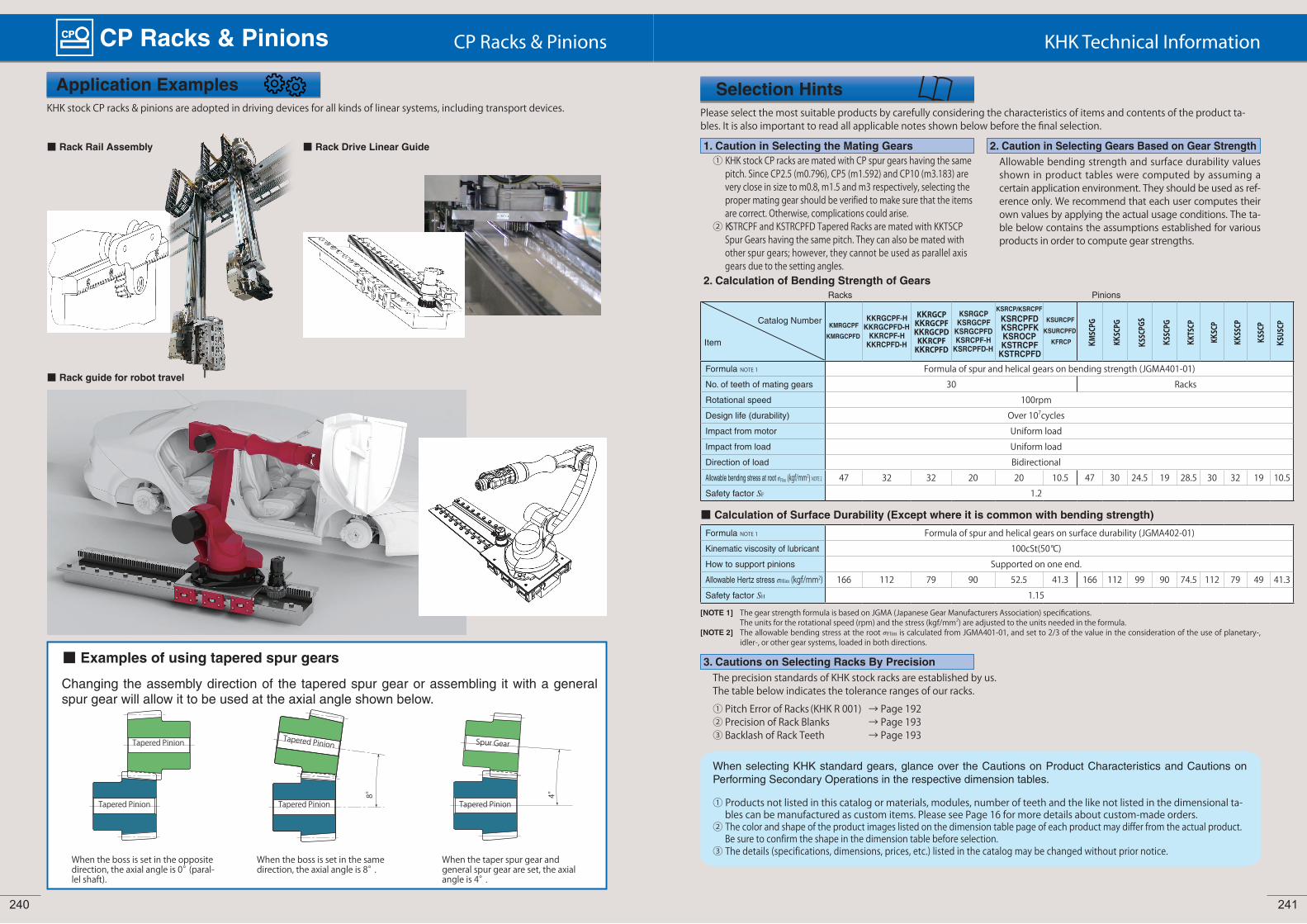
Application ExamplesKHK stock CP racks & pinions are adopted in driving devices for all kinds of linear systems, including transport devices.
■ Rack Rail Assembly ■ Rack Drive Linear Guide
■ Rack guide for robot travel
■ Examples of using tapered spur gears
When the boss is set in the opposite direction, the axial angle is 0° (paral-lel shaft).
When the boss is set in the same direction, the axial angle is 8°.
When the taper spur gear and general spur gear are set, the axial angle is 4°.
Tapered Pinion
Tapered Pinion Tapered Pinion Tapered Pinion
Tapered Pinion Spur Gear
8° 4°
Changing the assembly direction of the tapered spur gear or assembling it with a general spur gear will allow it to be used at the axial angle shown below.
Please select the most suitable products by carefully considering the characteristics of items and contents of the product ta-bles. It is also important to read all applicable notes shown below before the final selection.
Selection Hints
Allowable bending strength and surface durability values shown in product tables were computed by assuming a certain application environment. They should be used as ref-erence only. We recommend that each user computes their own values by applying the actual usage conditions. The ta-ble below contains the assumptions established for various products in order to compute gear strengths.
Catalog Number
Item
KMRGCPFKMRGCPFD
KKRGCPF-HKKRGCPFD-HKKRCPF-HKKRCPFD-H
KKRGCPKKRGCPFKKRGCPD
KKRCPFKKRCPFD
KSRGCPKSRGCPFKSRGCPFDKSRCPF-HKSRCPFD-H
KSRCP/KSRCPFKSRCPFDKSRCPFKKSROCPKSTRCPFKSTRCPFD
KSURCPFKSURCPFD
KFRCP KMSC
PG
KKSC
PG
KSSC
PGS
KSSC
PG
KKTS
CP
KKSC
P
KKSS
CP
KSSC
P
KSUS
CP
Formula NOTE 1 Formula of spur and helical gears on bending strength (JGMA401-01)No. of teeth of mating gears 30 RacksRotational speed 100rpmDesign life (durability) Over 107cyclesImpact from motor Uniform loadImpact from load Uniform loadDirection of load BidirectionalAllowable bending stress at root σFlim (kgf/mm2) NOTE 2 47 32 32 20 20 10.5 47 30 24.5 19 28.5 30 32 19 10.5Safety factor SF 1.2
Formula NOTE 1 Formula of spur and helical gears on surface durability (JGMA402-01)Kinematic viscosity of lubricant 100cSt(50°C)How to support pinions Supported on one end.Allowable Hertz stress σHlim (kgf/mm2) 166 112 79 90 52.5 41.3 166 112 99 90 74.5 112 79 49 41.3Safety factor SH 1.15
1. Caution in Selecting the Mating Gears① KHK stock CP racks are mated with CP spur gears having the same
pitch. Since CP2.5 (m0.796), CP5 (m1.592) and CP10 (m3.183) are very close in size to m0.8, m1.5 and m3 respectively, selecting the proper mating gear should be verified to make sure that the items are correct. Otherwise, complications could arise.
② KSTRCPF and KSTRCPFD Tapered Racks are mated with KKTSCP Spur Gears having the same pitch. They can also be mated with other spur gears; however, they cannot be used as parallel axis gears due to the setting angles.
2. Calculation of Bending Strength of Gears
■ Calculation of Surface Durability (Except where it is common with bending strength)
[NOTE 1] The gear strength formula is based on JGMA (Japanese Gear Manufacturers Association) specifications. The units for the rotational speed (rpm) and the stress (kgf/mm2) are adjusted to the units needed in the formula.
[NOTE 2] The allowable bending stress at the root σFlim is calculated from JGMA401-01, and set to 2/3 of the value in the consideration of the use of planetary-, idler-, or other gear systems, loaded in both directions.
2. Caution in Selecting Gears Based on Gear Strength
Racks Pinions
The precision standards of KHK stock racks are established by us.The table below indicates the tolerance ranges of our racks.
3. Cautions on Selecting Racks By Precision
① Pitch Error of Racks (KHK R 001) → Page 192② Precision of Rack Blanks → Page 193③ Backlash of Rack Teeth → Page 193
When selecting KHK standard gears, glance over the Cautions on Product Characteristics and Cautions on Performing Secondary Operations in the respective dimension tables.
① Products not listed in this catalog or materials, modules, number of teeth and the like not listed in the dimensional ta-bles can be manufactured as custom items. Please see Page 16 for more details about custom-made orders.
② The color and shape of the product images listed on the dimension table page of each product may differ from the actual product. Be sure to confirm the shape in the dimension table before selection.
③ The details (specifications, dimensions, prices, etc.) listed in the catalog may be changed without prior notice.
240 241

In order to use KHK stock CP racks safely, carefully read the Application Hints before proceeding. If there are questions or you require clarifications, please contact our technical department or your nearest distributor.
① Secondary operations can be performed on all KHKstock CP racks except for the racks where the gear teethare induction hardened. The precision of ground racksand racks with mounting holes may drop if you do notexercise extreme caution during installation or whilemodifying.
② Pitch lines of racks are controlled by using the bottomsurface as the reference datum and over-pin measure-ments on tooth thickness. If you machine the bottomsurfaces, the precision of the racks may be affected.
③ When connecting two racks, the machining of the mat-ing end pitch (CP) requires careful consideration. Themeshing will be poor if the pitch straddling the connec-tion has a positive tolerance. We recommend a minustolerance on pitch of at the connection. The below is anindication of pitch tolerance for each module.
Unit: mmCP Tolerance
CP2.5 -0.05-0.25
CP5 -0.1-0.3
CP10-0.1-0.4CP15
CP20
CP
④ To use dowel pins to secure racks, attach the racks to thebase and drill both simultaneously.
⑤ KHK stock CP racks made of S45C and SCM440 (exceptfor ground racks) can be induction hardened. However,the precision of pitch is decreased.
⑥ To be able to handle parts safely, all burrs and sharp cor-ners should be removed after the secondary operationsare done.
⑦ If you are going to modify the gear by gripping theteeth, please exercise caution not to crush the teethby applying too much pressure. Any scarring will causenoise during operation.
① KHK stock CP racks are designed to give the proper normal direction backlash when assembled using the mounting distance given by the formula below (mounting distance tolerance of H7 to H8 required). The backlash values are giv-en in the table on Page 193. Make sure that the mounting distance stays constant for the length of the rack.
Mounting distance a = Height of pitch line of rack + Pitch radius of pinion
Pinion
Rack
[NOTE] Pinions are assumed to be standard stock spur gears (x=0).
② KKRGCP type of KHK stock ground racks have four surfaces ground parallel to within 10 ~ 15μm. In order to maintain the straightness, set it on a mounting base with high accu-racy as shown below to correct the straightness error of the rack gear. Recently, no-backlash drive is often required, so assemble as shown below.
③ If the racks are not secured properly to the base, they could shift during operation and cause unexpected problems.It is very important to insure firm mounting by the use of dowel pins or similar devices.
④
⑤
Machined end type racks such as KSRCPF and KSRCPFD series have pitch tolerance of -0.05 to -0.4mm at the end face. If you try to connect the racks without any space, the pitch at the connection will be too small and will cause problems. Please follow the following diagrams for assembly. With KSRCPFD etc., if using more than 10 racks connected together to form a rack with mounting holes machined along a length of 1 meter, the pitch precision and machining precision may cause the rack and base mounting holes to deviate, leading to set screw interference with the counterbored hole and preventing mounting. When using a rack for long lengths such as 10 meters or 20 meters, have the mounting holes additionally machined into long holes.
Application Hints
2. Caution on Performing Secondary Operations
3. Points of Caution during Assembly1. Cautions on Handling
① KHK products are packaged one by one to preventscratches and dents, but if you find issues such as rust,scratches, or dents when the product is removed fromthe box after purchase, please contact the supplier.
② Depending on the handling method, the product may be-come deformed or damaged. Long racks and round racks deform particularly easily, so please handle with care.
SR2-100 (joining rack)
Mounting base
0.2 to 0.6SRFD2-1000
Reamer hole
SRFD2-1000
How to mount racks on a mounting base (For SRFD2-1000)
1. Pitch alignmentPlace SRFD2-1000 on the mounting base, align SR2-100 and temporarily tighten the bolt.
2. Securing to the mounting baseTap with a plastic hammer, bring it into close contact with the mounting base, and further tighten the bolt.(When using a metal hammer, be careful not to damage the gear teeth by using a stiffening plate, etc.)
3. Run the pinion and check the following ① Is there abnormal noise or vibration? ② Is the backlash appropriate? ③ Is there poor edge contact of
gear teeth?
SRFD2-1000 is designed to have a gap of 0.2 to 0.6 mm.
SR2-100 (joining rack)
SRFD2-1000SRFD2-1000
Mounting base
Mounting base
4. Secure fixation to the mounting base We recommend that you tap the knock pin so that the rack does not shift due to vibration, etc.① Simultaneously machine reamer holes
Mounting base
Drill
Knock pin② Drive the knock pin
Mounting base
Tighten again after tapping the knock pin.It can be marked with a pen to find looseness.
Stiffening Plate
105.3
Dimensions Table F Value x 2
KHK considers safety a priority in the use of our products.When handling, adding secondary operations, assembling, and operating KHK products, please be aware of the following issues in order to prevent accidents.
Warning: Precautions for preventing physical and property damage
Caution Cautions in Preventing Accidents
1. When using KHK products, follow relevant safety regulations (Occupational Safety and Health Regulations, etc.).2. Pay attention to the following items when installing, removing, or performing maintenance and inspection of the product.
① Turn off the power switch.② Do not reach or crawl under the product.③ Wear appropriate clothing and protective equipment for the work.
1. Before using a KHK product, read the precautions in the catalog carefully in order to use it correctly.2. Avoid use in environments that may adversely affect the product.3. Our products are manufactured under a superior quality control system based on the ISO9000 quality management system; if you
notice any malfunctions upon purchasing a product, please contact the supplier.
As an example of Rack Joining, we recommend the following method.
Joining Rack
[NOTE] Joining gauge racks for helical racks must have the opposite hand from the racks. Please use 100 mm long racks as a join-ing gauge rack, or alternatively the rack of the same specifi-cations on hand.
d
4. Cautions on Starting
① Check the following items before starting.• Are the gears installed securely?• Is there uneven tooth contact?• Is there adequate backlash? Be sure to avoid zero-backlash.• Has proper lubrication been supplied?
② If gears are exposed, be sure to attach a safety cover to ensure safety. Also, be careful not to touch rotating gears.
③ Gears can be lubricated with the "grease lubrication meth-od", "splash lubrication method (oil bath method)", or "forced lubrication method (circulation lubrication method)".
For initial operation, the lubricant may deteriorate markedly, so check the condition of the lubricant after starting.For more technical information, please see the section "Gear Lubrication" (Page 112) of our technical reference book.
④ If there is any abnormality such as noise or vibrationduring startup, check the gears and assembly condition."High gear accuracy", "smooth gear teeth surface"and"correct tooth contact" are some of the measuresagainst gear noise. For more technical information,please see the section "Gear Noise and Countermea-sures" (Page 119) of our technical reference book.
KSR2-100 (joining rack)
Mounting base
0.2 to 0.6
Reamer hole
KSRFD2-1000
How to mount racks on a mounting base (For SRFD2-1000)
1. Pitch alignmentPlace KSRFD2-1000 on the mounting base, align SR2-100 and temporarily tighten the bolt.
2. Securing to the mounting baseTap with a plastic hammer, bring it into close contact with the mounting base, and further tighten the bolt.(When using a metal hammer, be careful not to damage the gear teeth by using a stiffening plate, etc.)
3. Run the pinion and check the following① Is there abnormal noise or vibration?② Is the backlash appropriate?③ Is there poor edge contact of
gear teeth?
SRFD2-1000 is designed to have a gap of 0.2 to 0.6 mm.
Mounting base
Mounting base
SRFD2-1000SRFD2-1000
4. Secure fixation to the mounting baseWe recommend that you tap the knock pin so that the rack does not shift due to vibration, etc.① Simultaneously machine reamer holes
Mounting base
SRFD2-1000SRFD2-1000
Drill
Knock pin② Drive the knock pin
Mounting base
SRFD2-1000SRFD2-1000
Tighten again after tapping the knock pin.It can be marked with a pen to find looseness.
Stiffening Plate
105.3
Dimensions Table F Value x 2
KHK Technical InformationCP Racks & Pinions CP Racks & Pinions
How to mount racks on a mounting base (For KSRFD2-1000)
242 243
KSRFD2-1000
KSRFD2-1000 KSRFD2-1000
KSRFD2-1000 KSRFD2-1000
KSRFD2-1000 KSRFD2-1000
KSRFD2-1000 KSRFD2-1000
KSR2-100 (joining rack)