Embed Size (px)
Citation preview

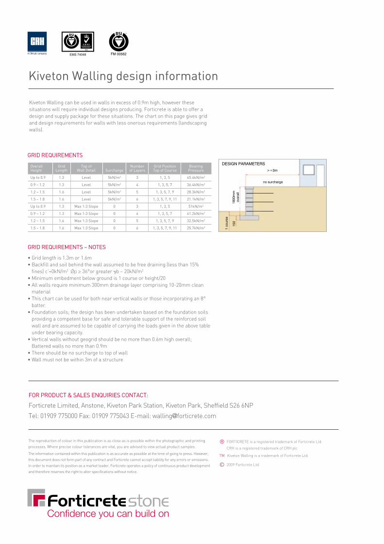
Kiveton Walling can be used in walls in excess of 0.9m high, however these situations will require individual designs producing. Forticrete is able to offer a design and supply package for these situations. The chart on this page gives grid and design requirements for walls with less onerous requirements (landscaping walls).
CI/SfB
April 2009
(Ff2)
The natural appeal of dry-stone retaining walls
Kiveton Walling
FOR PRODUCT & SALES ENQUIRIES CONTACT:
Forticrete Limited, Anstone, Kiveton Park Station, Kiveton Park, Sheffield S26 6NP
Tel: 01909 775000 Fax: 01909 775043 E-mail: [email protected]
® FORTICRETE is a registered trademark of Forticrete Ltd.
CRH is a registered trademark of CRH plc
TM Kiveton Walling is a trademark of Forticrete Ltd.
© 2009 Forticrete Ltd.
FM 00562
Kiveton Walling design information
The reproduction of colour in this publication is as close as is possible within the photographic and printing
processes. Where precise colour tolerances are vital, you are advised to view actual product samples.
The information contained within this publication is as accurate as possible at the time of going to press. However,
this document does not form part of any contract and Forticrete cannot accept liability for any errors or omissions.
In order to maintain its position as a market leader, Forticrete operates a policy of continuous product development
and therefore reserves the right to alter specifications without notice.
EMS 74048
Each stone is 300mm deep and the system comprises stones of three different face sizes, which can be used in single size or combined to create a random effect. On the bottom rear face of each unit is a series of slots, provided to accept high strength plastic pins that locate into the stones in one of two ways. One way aligns the back faces of the units to create a near vertical wall. Turn the pin round and slot it in the alternative way and it aligns the units 20mm further back than the unit below, creating a traditional battered wall. Capping units complete the natural walling effect.Units are manufactured and supplied with both smooth and split side faces, so returns are created simply. Standard units have parallel sides, for creating straight walls or concave curves. Stones with specially shaped sides are supplied to order that enable the creation of convex curves with a minimum radius of 1355mm achievable using the 225mm face size. Walls with random sizes will achieve varying radii, depending on the blend of sizes chosen.
Packaging and deliveryKiveton Walling stones are delivered on pallets of same size units and each pallet contains enough units to create just over 2 square metres of wall. Capping units are supplied with approx. 32 linear metres per pallet. Pins are supplied in packs of 50 or 100.
Standard units
225 x 140mm face size 300 x 140mm face size
225 x 140mm face size 300 x 140mm face size 450 x 140mm face size
450 x 140mm face size
Shaped units for convex curves
Unit Face Size (mm) Typical Dry Quantity Typical Dry Unit Weight (kg) Per Pack Pack Weight (kg)
Walling Straight 225 x 140 19.6 72 1412
Walling Straight 300 x 140 25.4 54 1373
Walling Straight 450 x 140 39.2 36 1412
Walling Curved 225/175 x 140 18.1 72 1302
Walling Curved 300/250 x 140 23.9 54 1290
Walling Curved 450/400 x 140 37.7 36 1357
Capping Straight 225 x 65 9.0 144 1297
Capping Straight 300 x 65 12.2 108 1323
Capping Straight 450 x 65 18.0 72 1296
Capping Curved 225/175 x 65 7.9 144 1133
Capping Curved 300/250 x 65 11.1 108 1198
Capping Curved 450/400 x 65 17.0 72 1223
Kiveton range
(300mm) (300mm)
HEIGHTVARIES
CAP 65mm
150mm BASE LEVELLINGPAD
CRUSHEDSTONE
10 - 20 mm
DRAINAGEMATERIAL
GEOGRIDREINFORCEMENT
REINFORCEDFILL
This pin position will align a wall in the ‘near vertical’ position.
Vertical wall pin position
Battered wall pin position
80
(300mm) (300mm)
HEIGHTVARIES
CAP 65mm
150mm
CRUSHEDSTONE
10 - 20 mm
DRAINAGEMATERIAL
GEOGRIDREINFORCEMENT
REINFORCEDFILL
BASE LEVELLINGPAD
Stepped batter GRID REQUIREmENTS – NOTES
• Grid length is 1.3m or 1.6m• Backfill and soil behind the wall assumed to be free draining (less than 15%
fines) c’=0kN/m2 Ǿp ≥ 36°or greater gb – 20kN/m2
• Minimum embedment below ground is 1 course or height/20• All walls require minimum 300mm drainage layer comprising 10-20mm clean
material• This chart can be used for both near vertical walls or those incorporating an 8°
batter.• Foundation soils; the design has been undertaken based on the foundation soils
providing a competent base for safe and tolerable support of the reinforced soil wall and are assumed to be capable of carrying the loads given in the above table under bearing capacity.
• Vertical walls without geogrid should be no more than 0.6m high overall; Battered walls no more than 0.9m
• There should be no surcharge to top of wall• Wall must not be within 3m of a structure
Overall Grid Top of Number Grid Position Bearing Height Length Wall Detail Surcharge of Layers Top of Course Pressure
Up to 0.9 1.3 Level 5kN/m2 3 1, 3, 5 45.4kN/m2
0.9 – 1.2 1.3 Level 5kN/m2 4 1, 3, 5, 7 36.4kN/m2
1.2 – 1.5 1.6 Level 5kN/m2 5 1, 3, 5, 7, 9 28.3kN/m2
1.5 – 1.8 1.6 Level 5kN/m2 6 1, 3, 5, 7, 9, 11 21.1kN/m2
Up to 0.9 1.3 max 1:3 Slope 0 3 1, 3, 5 51kN/m2
0.9 – 1.2 1.3 max 1:3 Slope 0 4 1, 3, 5, 7 41.2kN/m2
1.2 – 1.5 1.6 max 1:3 Slope 0 5 1, 3, 5, 7, 9 32.5kN/m2
1.5 – 1.8 1.6 max 1:3 Slope 0 6 1, 3, 5, 7, 9, 11 25.7kN/m2
GRID REQUIREmENTS
High strength alignment pins
Confidence you can build onConfidence you can build on
>=3m
1800
mm
ov
eral
l15
0 1
cour
se
DESIGN PARAMETERS
no surcharge
Using this pin position on all courses will build the wall with an approximate 8° batter (setback). This is a 20mm setback for each 140mm of vertical wall.
80
(300mm) (300mm)
HEIGHTVARIES
CAP 65mm
150mm
CRUSHEDSTONE
10 - 20 mm
DRAINAGEMATERIAL
GEOGRIDREINFORCEMENT
REINFORCEDFILL
BASE LEVELLINGPAD
Raked batter

Kiveton Walling Simple, effective dry-stone wallsKiveton Walling is a dry-build retaining wall system that enables the simple creation of low height gravity landscape walls or taller reinforced soil wall structures capable of handling surcharge loads. Evoking the old-world charm of a mason-crafted wall, Kiveton Walling is available in a range of colours and face finishes that match many of the regional stone variations prevalent throughout the UK.
There is a choice of four colours and two face finish options – a rugged split face and a pitched face, which is a rough effect whereby each stone has a raised centre, typical of quarry-dressed stone. Both of these finishes can be laid to create vertical or stepped battered walls. To create a continuous battered wall, there is a product with a raked face, the bottom half of which is split and the top half of which is raked back by 20mm to create a natural battered effect when laid.
Pitched Face
Split Face
Finishes
Buff
Black Old Weathered
Brown Old Weathered
Natural
Colours

Kiveton Walling can be used in walls in excess of 0.9m high, however these situations will require individual designs producing. Forticrete is able to offer a design and supply package for these situations. The chart on this page gives grid and design requirements for walls with less onerous requirements (landscaping walls).
CI/SfB
April 2009
(Ff2)
The natural appeal of dry-stone retaining walls
Kiveton Walling
FOR PRODUCT & SALES ENQUIRIES CONTACT:
Forticrete Limited, Anstone, Kiveton Park Station, Kiveton Park, Sheffi eld S26 6NP
Tel: 01909 775000 Fax: 01909 775043 E-mail: [email protected]
® FORTICRETE is a registered trademark of Forticrete Ltd.
CRH is a registered trademark of CRH plc
TM Kiveton Walling is a trademark of Forticrete Ltd.
© 2009 Forticrete Ltd.
FM 00562
Kiveton Walling design information
The reproduction of colour in this publication is as close as is possible within the photographic and printing
processes. Where precise colour tolerances are vital, you are advised to view actual product samples.
The information contained within this publication is as accurate as possible at the time of going to press. However,
this document does not form part of any contract and Forticrete cannot accept liability for any errors or omissions.
In order to maintain its position as a market leader, Forticrete operates a policy of continuous product development
and therefore reserves the right to alter specifications without notice.
EMS 74048
Each stone is 300mm deep and the system comprises stones of three different face sizes, which can be used in single size or combined to create a random effect. On the bottom rear face of each unit is a series of slots, provided to accept high strength plastic pins that locate into the stones in one of two ways. One way aligns the back faces of the units to create a near vertical wall. Turn the pin round and slot it in the alternative way and it aligns the units 20mm further back than the unit below, creating a traditional battered wall. Capping units complete the natural walling effect.Units are manufactured and supplied with both smooth and split side faces, so returns are created simply. Standard units have parallel sides, for creating straight walls or concave curves. Stones with specially shaped sides are supplied to order that enable the creation of convex curves with a minimum radius of 1355mm achievable using the 225mm face size. Walls with random sizes will achieve varying radii, depending on the blend of sizes chosen.
Packaging and deliveryKiveton Walling stones are delivered on pallets of same size units and each pallet contains enough units to create just over 2 square metres of wall. Capping units are supplied with approx. 32 linear metres per pallet. Pins are supplied in packs of 50 or 100.
Standard units
225 x 140mm face size 300 x 140mm face size
225 x 140mm face size 300 x 140mm face size 450 x 140mm face size
Standard units
225 x 140mm face size 300 x 140mm face size 450 x 140mm face size
225 x 140mm face size 300 x 140mm face size 450 x 140mm face size
Shaped units for convex curves
Unit Face Size (mm) Typical Dry Quantity Typical Dry Unit Weight (kg) Per Pack Pack Weight (kg)
Walling Straight 225 x 140 19.6 72 1412
Walling Straight 300 x 140 25.4 54 1373
Walling Straight 450 x 140 39.2 36 1412
Walling Curved 225/175 x 140 18.1 72 1302
Walling Curved 300/250 x 140 23.9 54 1290
Walling Curved 450/400 x 140 37.7 36 1357
Capping Straight 225 x 65 9.0 144 1297
Capping Straight 300 x 65 12.2 108 1323
Capping Straight 450 x 65 18.0 72 1296
Capping Curved 225/175 x 65 7.9 144 1133
Capping Curved 300/250 x 65 11.1 108 1198
Capping Curved 450/400 x 65 17.0 72 1223
Kiveton range
(300mm) (300mm)
HEIGHTVARIES
CAP 65mm
150mm BASE LEVELLINGPAD
CRUSHEDSTONE
10 - 20 mm
DRAINAGEMATERIAL
GEOGRIDREINFORCEMENT
REINFORCEDFILL
This pin position will align a wall in the ‘near vertical’ position.
Vertical wall pin position
Battered wall pin position
80
(300mm) (300mm)
HEIGHTVARIES
CAP 65mm
150mm
CRUSHEDSTONE
10 - 20 mm
DRAINAGEMATERIAL
GEOGRIDREINFORCEMENT
REINFORCEDFILL
BASE LEVELLINGPAD
Stepped batter GRID REQUIREmENTS – NOTES
• Grid length is 1.3m or 1.6m• Backfill and soil behind the wall assumed to be free draining (less than 15%
fines) c’=0kN/m2 Ǿp ≥ 36°or greater gb – 20kN/m2
• Minimum embedment below ground is 1 course or height/20• All walls require minimum 300mm drainage layer comprising 10-20mm clean
material• This chart can be used for both near vertical walls or those incorporating an 8°
batter.• Foundation soils; the design has been undertaken based on the foundation soils
providing a competent base for safe and tolerable support of the reinforced soil wall and are assumed to be capable of carrying the loads given in the above table under bearing capacity.
• Vertical walls without geogrid should be no more than 0.6m high overall; Battered walls no more than 0.9m
• There should be no surcharge to top of wall• Wall must not be within 3m of a structure
Overall Grid Top of Number Grid Position Bearing Height Length Wall Detail Surcharge of Layers Top of Course Pressure
Up to 0.9 1.3 Level 5kN/m2 3 1, 3, 5 45.4kN/m2
0.9 – 1.2 1.3 Level 5kN/m2 4 1, 3, 5, 7 36.4kN/m2
1.2 – 1.5 1.6 Level 5kN/m2 5 1, 3, 5, 7, 9 28.3kN/m2
1.5 – 1.8 1.6 Level 5kN/m2 6 1, 3, 5, 7, 9, 11 21.1kN/m2
Up to 0.9 1.3 max 1:3 Slope 0 3 1, 3, 5 51kN/m2
0.9 – 1.2 1.3 max 1:3 Slope 0 4 1, 3, 5, 7 41.2kN/m2
1.2 – 1.5 1.6 max 1:3 Slope 0 5 1, 3, 5, 7, 9 32.5kN/m2
1.5 – 1.8 1.6 max 1:3 Slope 0 6 1, 3, 5, 7, 9, 11 25.7kN/m2
GRID REQUIREmENTS
High strength alignment pins
Confidence you can build onConfidence you can build on
>=3m
1800
mm
ov
eral
l15
0
1 co
urse
DESIGN PARAMETERS
no surcharge
Using this pin position on all courses will build the wall with an approximate 8° batter (setback). This is a 20mm setback for each 140mm of vertical wall.
80
(300mm) (300mm)
HEIGHTVARIES
CAP 65mm
150mm
CRUSHEDSTONE
10 - 20 mm
DRAINAGEMATERIAL
GEOGRIDREINFORCEMENT
REINFORCEDFILL
BASE LEVELLINGPAD
Raked batter

* For further advice on the correct levelling pad, please contact the Forticrete Technical Department.
1. Prepare the Base Levelling PadRemove all the surface vegetation and debris. Excavate the base trench to the designed width and depth. Level the prepared base with 150mm of C20/25 concrete.* If the foundation is to be stepped, start the levelling pad at the lowest elevation along the wall and step up as required in 140mm increments. At no point must you have less than one course or H/20 embedment.
2. Install the Base Course If your design includes the larger units, use the purpose-designed lifting tool to lift the stones into position ensuring that the pin holes are positioned to the rear facing down. Bed the first course in mortar. make sure each unit is level as this is critical for accurate and acceptable results. minimum embedment of base course is 140mm below grade.
4. Install Additional Courses As you lay the next course of stones, locate the plastic pins into the slots in the rear underside of the units, positioned dependant on whether the wall is to be vertical or battered. Push each unit forward until the pin locates against the rear of the stone below. Ensure that joints between one course of stones and the next is staggered, to avoid ‘stack bonding’.
Installation
3. Install Drainage Fill, Backfill & CompactionProvide a minimum of 300mm of non-cohesive drainage material behind the units. Fill any open spaces between the units with the same material. Proceed to place backfill in maximum 140mm layers and fully compact.
5. Installing Geogrid Where there is a requirement for the use of geogrid it will be necessary to excavate behind the wall in order to install the grid. Please refer to the table on the back page. The geogrid is placed over the stones as shown and held in place by the next layer of walling. Always allow a minimum 250mm of geogrid material to rest on the stones’ top face. This will ensure the next unit is fully supported on geogrid. Place all sections of geogrid abutting each other. Once you’ve laid the next course over the geogrid, pull the grid taut to eliminate loose folds, stake or secure back edge before backfill and compaction. Wherever possible, compact from back of wall towards embankment to avoid loosening geogrid or putting compaction pressure on the wall.
6. Capping the Wall Clean off the last course in preparation for the capping units. Use mortar to create a bond between the top course and the capping unit. The cap may be flush to the front or overhanging as required by the aesthetics and design.

(300mm) (300mm)
HEIGHTVARIES
CAP 65mm
150mm
BACKFILLDRAINAGEMATERIAL
BASE LEVELLINGPAD
NO SURCHARGE/LEVEL GRADE
80
(300mm) (300mm)
HEIGHTVARIES
CAP 65mm
150mm
BACKFILL
DRAINAGEMATERIAL
BASE LEVELLINGPAD
NO SURCHARGE/LEVEL GRADE
Gravity wall – near vertical (maximum 0.6 metres)
Gravity wall – 8º battered (maximum 0.9 metres)
(300mm) (300mm)
HEIGHTVARIES
CAP 65mm
150mm BASE LEVELLINGPAD
CRUSHEDSTONE
10 - 20 mm
DRAINAGEMATERIAL
GEOGRIDREINFORCEMENT
REINFORCEDFILL
80
(300mm) (300mm)
HEIGHTVARIES
CAP 65mm
150mm
CRUSHEDSTONE
10 - 20 mm
DRAINAGEMATERIAL
GEOGRIDREINFORCEMENT
REINFORCEDFILL
BASE LEVELLINGPAD
Reinforced wall – near vertical Reinforced wall – 8º battered
Embedment depth below grade minimum 1 unit or H/20
Embedment depth below grade minimum 1 unit or H/20
Wall types
Kiveton Walling can be used in walls in excess of 0.9m high, however these situations will require individual designs producing. Forticrete is able to offer a design and supply package for these situations. The chart on this page gives grid and design requirements for walls with less onerous requirements (landscaping walls).
CI/SfB
April 2009
(Ff2)
The natural appeal of dry-stone retaining walls
Kiveton Walling
FOR PRODUCT & SALES ENQUIRIES CONTACT:
Forticrete Limited, Anstone, Kiveton Park Station, Kiveton Park, Sheffield S26 6NP
Tel: 01909 775000 Fax: 01909 775043 E-mail: [email protected]
® FORTICRETE is a registered trademark of Forticrete Ltd.
CRH is a registered trademark of CRH plc
TM Kiveton Walling is a trademark of Forticrete Ltd.
© 2009 Forticrete Ltd.
FM 00562
Kiveton Walling design information
The reproduction of colour in this publication is as close as is possible within the photographic and printing
processes. Where precise colour tolerances are vital, you are advised to view actual product samples.
The information contained within this publication is as accurate as possible at the time of going to press. However,
this document does not form part of any contract and Forticrete cannot accept liability for any errors or omissions.
In order to maintain its position as a market leader, Forticrete operates a policy of continuous product development
and therefore reserves the right to alter specifications without notice.
EMS 74048
Each stone is 300mm deep and the system comprises stones of three different face sizes, which can be used in single size or combined to create a random effect. On the bottom rear face of each unit is a series of slots, provided to accept high strength plastic pins that locate into the stones in one of two ways. One way aligns the back faces of the units to create a near vertical wall. Turn the pin round and slot it in the alternative way and it aligns the units 20mm further back than the unit below, creating a traditional battered wall. Capping units complete the natural walling effect.Units are manufactured and supplied with both smooth and split side faces, so returns are created simply. Standard units have parallel sides, for creating straight walls or concave curves. Stones with specially shaped sides are supplied to order that enable the creation of convex curves with a minimum radius of 1355mm achievable using the 225mm face size. Walls with random sizes will achieve varying radii, depending on the blend of sizes chosen.
Packaging and deliveryKiveton Walling stones are delivered on pallets of same size units and each pallet contains enough units to create just over 2 square metres of wall. Capping units are supplied with approx. 32 linear metres per pallet. Pins are supplied in packs of 50 or 100.
Standard units
225 x 140mm face size 300 x 140mm face size
225 x 140mm face size 300 x 140mm face size 450 x 140mm face size
450 x 140mm face size
Shaped units for convex curves
Unit Face Size (mm) Typical Dry Quantity Typical Dry Unit Weight (kg) Per Pack Pack Weight (kg)
Walling Straight 225 x 140 19.6 72 1412
Walling Straight 300 x 140 25.4 54 1373
Walling Straight 450 x 140 39.2 36 1412
Walling Curved 225/175 x 140 18.1 72 1302
Walling Curved 300/250 x 140 23.9 54 1290
Walling Curved 450/400 x 140 37.7 36 1357
Capping Straight 225 x 65 9.0 144 1297
Capping Straight 300 x 65 12.2 108 1323
Capping Straight 450 x 65 18.0 72 1296
Capping Curved 225/175 x 65 7.9 144 1133
Capping Curved 300/250 x 65 11.1 108 1198
Capping Curved 450/400 x 65 17.0 72 1223
Kiveton range
(300mm) (300mm)
HEIGHTVARIES
CAP 65mm
150mm BASE LEVELLINGPAD
CRUSHEDSTONE
10 - 20 mm
DRAINAGEMATERIAL
GEOGRIDREINFORCEMENT
REINFORCEDFILL
This pin position will align a wall in the ‘near vertical’ position.
Vertical wall pin position
Battered wall pin position
80
(300mm) (300mm)
HEIGHTVARIES
CAP 65mm
150mm
CRUSHEDSTONE
10 - 20 mm
DRAINAGEMATERIAL
GEOGRIDREINFORCEMENT
REINFORCEDFILL
BASE LEVELLINGPAD
Stepped batter GRID REQUIREmENTS – NOTES
• Grid length is 1.3m or 1.6m• Backfill and soil behind the wall assumed to be free draining (less than 15%
fines) c’=0kN/m2 Ǿp ≥ 36°or greater gb – 20kN/m2
• Minimum embedment below ground is 1 course or height/20• All walls require minimum 300mm drainage layer comprising 10-20mm clean
material• This chart can be used for both near vertical walls or those incorporating an 8°
batter.• Foundation soils; the design has been undertaken based on the foundation soils
providing a competent base for safe and tolerable support of the reinforced soil wall and are assumed to be capable of carrying the loads given in the above table under bearing capacity.
• Vertical walls without geogrid should be no more than 0.6m high overall; Battered walls no more than 0.9m
• There should be no surcharge to top of wall• Wall must not be within 3m of a structure
Overall Grid Top of Number Grid Position Bearing Height Length Wall Detail Surcharge of Layers Top of Course Pressure
Up to 0.9 1.3 Level 5kN/m2 3 1, 3, 5 45.4kN/m2
0.9 – 1.2 1.3 Level 5kN/m2 4 1, 3, 5, 7 36.4kN/m2
1.2 – 1.5 1.6 Level 5kN/m2 5 1, 3, 5, 7, 9 28.3kN/m2
1.5 – 1.8 1.6 Level 5kN/m2 6 1, 3, 5, 7, 9, 11 21.1kN/m2
Up to 0.9 1.3 max 1:3 Slope 0 3 1, 3, 5 51kN/m2
0.9 – 1.2 1.3 max 1:3 Slope 0 4 1, 3, 5, 7 41.2kN/m2
1.2 – 1.5 1.6 max 1:3 Slope 0 5 1, 3, 5, 7, 9 32.5kN/m2
1.5 – 1.8 1.6 max 1:3 Slope 0 6 1, 3, 5, 7, 9, 11 25.7kN/m2
GRID REQUIREmENTS
High strength alignment pins
Confidence you can build onConfidence you can build on
>=3m
1800
mm
ov
eral
l15
0 1
cour
se
DESIGN PARAMETERS
no surcharge
Using this pin position on all courses will build the wall with an approximate 8° batter (setback). This is a 20mm setback for each 140mm of vertical wall.
80
(300mm) (300mm)
HEIGHTVARIES
CAP 65mm
150mm
CRUSHEDSTONE
10 - 20 mm
DRAINAGEMATERIAL
GEOGRIDREINFORCEMENT
REINFORCEDFILL
BASE LEVELLINGPAD
Raked batter