Embed Size (px)
Citation preview

KINEMATICS AND DYNAMICS ANALYSIS OF DIFFERENT MECHANISMS USING
THE SIMMECHANICS / SIMULINK / MATLAB
A.D. Perechesova (a), I.I. Kalapyshina
(b), K.A. Nuzhdin
(c)
(a) ITMO University, SPbF IZMIRAN (b) ITMO University, National Research University SPbSPU
(c) ITMO University, FAM - robotics
(a) [email protected],(b) [email protected], (c) [email protected]
ABSTRACT
The article shows the possibilities of modeling of spatial motions of a solid machines and a mechanisms using the library SimMechanics/Simulink/MATLAB. A two ways of kinematics analysis of the two-parametric antenna are shown: using the library SimMechanics and using the principles of matrix equations. Also work presents the comparison of the results. The article presents the SimMechanics model of tribometric system and the SimMechanics model of executing mechanism of the device for manufacturing torsion bars with Helical Anisotropy. The envelope of the cross-section of torsion bars is an ellipse with longer axis of 0.046 mm and shorter axis of 0.033 mm, the total length - 100 mm, the density of braiding –7 knots/mm.
Keywords: SimMechanics, MATLAB, modeling, two-parametric antenna, tribometric system, device for manufacturing torsion bars with Helical Anisotropy
1. INTRODUCTION It is more effective to use modeling with the help
of the SimMechanics library of the Simulink/MATLAB software for studying kinematics and dynamics of different mechanisms (Musalimov et al., 2013). Differential equations are presented in SimMechanics model diagram. Mechanical system is presented as associated block diagram. Blocks stand for models of mechanical joints, their position can change during cycle. SimMechanics translates our block to equivalent mathematical model. SimMechanics works with mechanical forces, but not with the signals.
This saves you the time and effort of developing the mathematical model yourself.
You can record simulation animations in Microsoft Audio Video Interleave® (AVI) format using the SimMechanics visualization. You can display signals generated during simulation and measure different parameters by the Scope blocks and the Sensor blocks.
2. OPERATION PRINCIPLES OF THE
SIMMECHANICS BASIC BLOCKS
The vectorial method can be used to describe blocks of the library SimMechanics Joints part.
The Revolute block (fig. 1, a) represents a single rotational degrees of freedom about a specified axis between two bodies. A matrix of direction cosine like (1) can be used to describe block.
),cos(),cos(),cos(
),cos(),cos(),cos(
),cos(),cos(),cos(
/\/\/\
/\/\/\
/\/\/\
ababab
ababab
ababab
ba
zzyzxz
zyyyxy
zxyxxx
M =
(1)
where [aaazyx ,, ] – initial coordinate system,
[ bbbzyx ,, ] – rotated coordinate system.
The rotational sense is defined by the right-hand rule. The Revolute block on fig. 1 (a) represents a single rotational degrees of freedom about z axis. The matrix of direction cosine of this block determined by (2), witch correspond with fig. 2, а.
100
0)cos()sin(
0)sin()cos(
baba
baba
z
baM ϕϕ
ϕϕ −
=
(2)
a
b
c
d
e
Figure 1. The Joints Blocks
Proceedings of the European Modeling and Simulation Symposium, 2014 978-88-97999-38-6; Affenzeller, Bruzzone, Jiménez, Longo, Merkuryev, Zhang Eds.
128
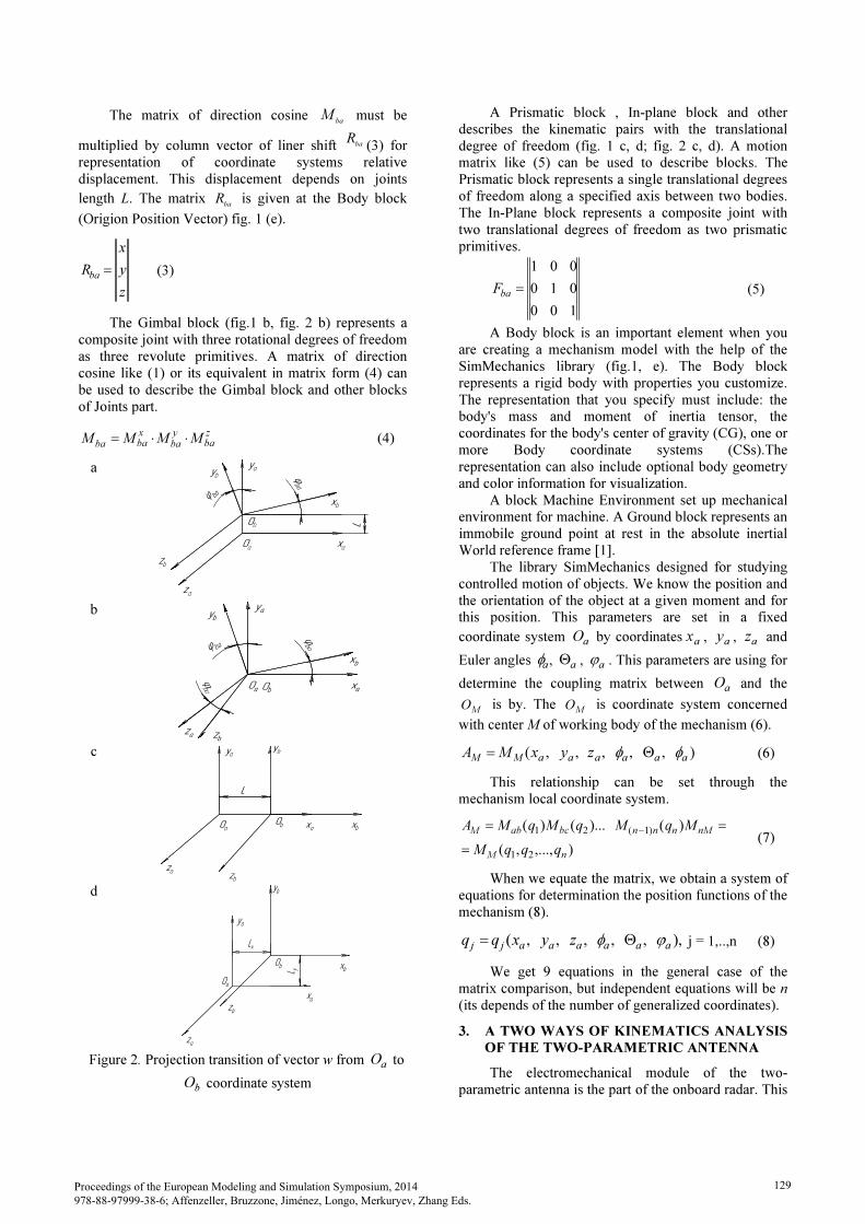
The matrix of direction cosine baM must be
multiplied by column vector of liner shift baR
(3) for representation of coordinate systems relative displacement. This displacement depends on joints
length L. The matrix baR is given at the Body block
(Origion Position Vector) fig. 1 (e).
z
y
x
Rba= (3)
The Gimbal block (fig.1 b, fig. 2 b) represents a composite joint with three rotational degrees of freedom as three revolute primitives. A matrix of direction cosine like (1) or its equivalent in matrix form (4) can be used to describe the Gimbal block and other blocks of Joints part.
zba
yba
xbaba MMMM ⋅⋅= (4)
а
b
c
d
Figure 2. Projection transition of vector w from а
О to
bО coordinate system
A Prismatic block , In-plane block and other describes the kinematic pairs with the translational degree of freedom (fig. 1 c, d; fig. 2 c, d). A motion matrix like (5) can be used to describe blocks. The Prismatic block represents a single translational degrees of freedom along a specified axis between two bodies. The In-Plane block represents a composite joint with two translational degrees of freedom as two prismatic primitives.
100
010
001
=ba
F (5)
A Body block is an important element when you are creating a mechanism model with the help of the SimMechanics library (fig.1, e). The Body block represents a rigid body with properties you customize. The representation that you specify must include: the body's mass and moment of inertia tensor, the coordinates for the body's center of gravity (CG), one or more Body coordinate systems (CSs).The representation can also include optional body geometry and color information for visualization.
A block Machine Environment set up mechanical environment for machine. A Ground block represents an immobile ground point at rest in the absolute inertial World reference frame [1].
The library SimMechanics designed for studying controlled motion of objects. We know the position and the orientation of the object at a given moment and for this position. This parameters are set in a fixed
coordinate system aO by coordinates
ax ,
ay ,
az and
Euler angles aφ ,
aΘ , aϕ . This parameters are using for
determine the coupling matrix between aO and the
MO is by. The
MO is coordinate system concerned
with center M of working body of the mechanism (6).
),,,,,(aaaaaaMM
zyxMA φφ Θ=
(6)
This relationship can be set through the mechanism local coordinate system.
),...,,(
)()...()(
21
)1(21
nM
nMnnnbcabM
qqqM
MqMqMqMA
=
==−
(7)
When we equate the matrix, we obtain a system of equations for determination the position functions of the mechanism (8).
),,,,,,( aaaaaajj zyxqq ϕφ Θ= j = 1,..,n (8)
We get 9 equations in the general case of the matrix comparison, but independent equations will be n (its depends of the number of generalized coordinates).
3. A TWO WAYS OF KINEMATICS ANALYSIS OF THE TWO-PARAMETRIC ANTENNA
The electromechanical module of the two-parametric antenna is the part of the onboard radar. This
Îà
Îb
xà
xb
yb
zà
zb
ya
L
jba
j ba
Îà
Îb
xà
xb
yb
zà
zb
ya
L
jba
j ba
Îà
zà
ya
xb
xà
yb
zb
Îb
jbaj b a
jba Î
à
zà
ya
xb
xà
yb
zb
Îb
jbaj b a
jba
xà
Îà
zà
ya
zb
yb
xbÎb
L
xà
Îà
zà
ya
zb
yb
xbÎb
L
ya
Îà
zà
xà
Îb x
b
zb
L y
Lx
yb
ya
zà
xà
Îb x
b
zb
L y
Lx
yb
Proceedings of the European Modeling and Simulation Symposium, 2014 978-88-97999-38-6; Affenzeller, Bruzzone, Jiménez, Longo, Merkuryev, Zhang Eds.
129
radar working in the UHF waveband range (Zamoruev et al., 2012).
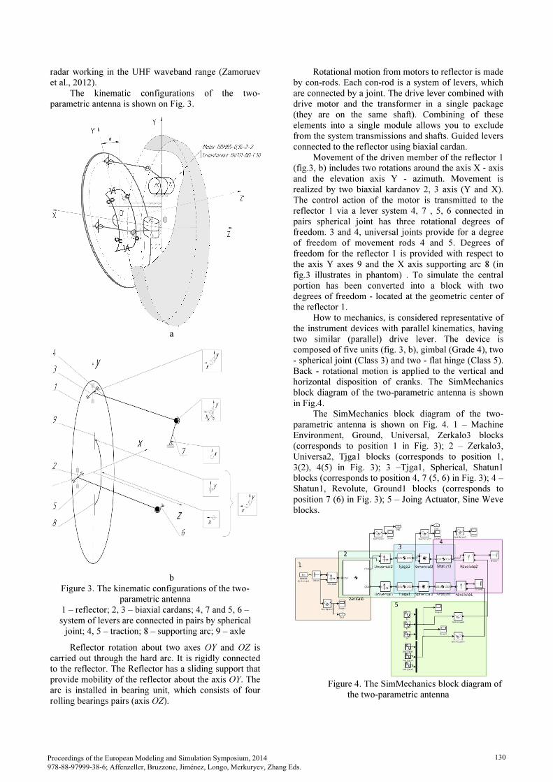
The kinematic configurations of the two-parametric antenna is shown on Fig. 3.
a
b
Figure 3. The kinematic configurations of the two-parametric antenna
1 – reflector; 2, 3 – biaxial cardans; 4, 7 and 5, 6 – system of levers are connected in pairs by spherical
joint; 4, 5 – traction; 8 – supporting arc; 9 – axle
Reflector rotation about two axes OY and OZ is carried out through the hard arc. It is rigidly connected to the reflector. The Reflector has a sliding support that provide mobility of the reflector about the axis OY. The arc is installed in bearing unit, which consists of four rolling bearings pairs (axis OZ).
Rotational motion from motors to reflector is made by con-rods. Each con-rod is a system of levers, which are connected by a joint. The drive lever combined with drive motor and the transformer in a single package (they are on the same shaft). Combining of these elements into a single module allows you to exclude from the system transmissions and shafts. Guided levers connected to the reflector using biaxial cardan.
Movement of the driven member of the reflector 1 (fig.3, b) includes two rotations around the axis X - axis and the elevation axis Y - azimuth. Movement is realized by two biaxial kardanov 2, 3 axis (Y and X). The control action of the motor is transmitted to the reflector 1 via a lever system 4, 7 , 5, 6 connected in pairs spherical joint has three rotational degrees of freedom. 3 and 4, universal joints provide for a degree of freedom of movement rods 4 and 5. Degrees of freedom for the reflector 1 is provided with respect to the axis Y axes 9 and the X axis supporting arc 8 (in fig.3 illustrates in phantom) . To simulate the central portion has been converted into a block with two degrees of freedom - located at the geometric center of the reflector 1.
How to mechanics, is considered representative of the instrument devices with parallel kinematics, having two similar (parallel) drive lever. The device is composed of five units (fig. 3, b), gimbal (Grade 4), two - spherical joint (Class 3) and two - flat hinge (Class 5). Back - rotational motion is applied to the vertical and horizontal disposition of cranks. The SimMechanics block diagram of the two-parametric antenna is shown in Fig.4.
The SimMechanics block diagram of the two-parametric antenna is shown on Fig. 4. 1 – Machine Environment, Ground, Universal, Zerkalo3 blocks (corresponds to position 1 in Fig. 3); 2 – Zerkalo3, Universa2, Tjga1 blocks (corresponds to position 1, 3(2), 4(5) in Fig. 3); 3 –Tjga1, Spherical, Shatun1 blocks (corresponds to position 4, 7 (5, 6) in Fig. 3); 4 – Shatun1, Revolute, Ground1 blocks (corresponds to position 7 (6) in Fig. 3); 5 – Joing Actuator, Sine Weve blocks.
Figure 4. The SimMechanics block diagram of
the two-parametric antenna
Proceedings of the European Modeling and Simulation Symposium, 2014 978-88-97999-38-6; Affenzeller, Bruzzone, Jiménez, Longo, Merkuryev, Zhang Eds.
130

The SimMechanics animated model of the two-
parametric antenna is shown on Fig. 5. Joint Sensor
blocks from model (fig. 4) measures the position,
velocity, and/or acceleration of a joint primitive in a
Joint block. It also measures the reaction force and
torque across the Joint.
a
b
Figure 5. The SimMechanics animated model of
the two-parametric antenna (a), analytical solution (b)
Was written a system of 12 equations which
determine the position of each element of the two-
parameter antenna. Fig. 5 (b) shows the zero position of
the mechanical system.
Following is a comparison of the analytical model
and the SimMechanics model. The main parameter for
comparison of the models was adopted the position of
the reflector about the axes X and Y, and the input angle
of con- rods. Angular positions are set to each rod from
0o
to 40o
.
Fig. 6 shows results of the comparison of the
SimMechanics model and the analytical model: (a) the
result of the SimMechanics model; (b) the result of the
analytical model; (c) the average values of the position
of the SimMechanics and the analytical models.
Figure 6 (a) shows that for small angles deviation
of con-rod, there is an overlapping of graphs, which
characterize the deviation of the reflector in the X and Y
(two degrees of freedom). The result of the
SimMechanics model shows divergence of angles
deflection of reflector becomes intensely increasing
after 17 º. The analytical model (Fig. 6, b) shows the
same result. The maximum value of the results variation
between the average values of data from the two models
equal /
max31≈∆ (fig.6, c).
a
b
c
Figure 6. Results of the comparison of the
SimMechanics model and the analytical mode
Proceedings of the European Modeling and Simulation Symposium, 2014 978-88-97999-38-6; Affenzeller, Bruzzone, Jiménez, Longo, Merkuryev, Zhang Eds.
131

Possible to conclude that the analytical solutions and models SimMechanics are coincide. The maximum
value of the results variation /
max31≈∆ in a range of
con-rod positions from 0 º to 40 º, with intensely divergence after 25 º (of rods). It is important, that the position of the con-rod equal 15 º is the maximum for the two-parametric antenna specifications.
4. THE SIMMECHANICS MODEL OF THE TRIBOMETRIC SYSTEM
The tribometric system "Tribal-2" was created at the Mechatronics Department of ITMO University. This system designed to investigate and identification of friction processes, which occur because of the reciprocating motion of the test samples relative to each other. The kinematic configuration of the tribometric system is shown in Fig. 7.
Figure 7. The kinematic configurations of the
tribometric system 1 - base; 2,3 - upper and lower platforms,
accordingly; 4 – guide of the lower platform; 5 - guide of the upper platform; 6 - spring; 7 - vertical
guide; 8 - crankgear; 9 - motor
Tribometric system consists of a base 1, two platforms: the lower 2 and the upper 3. Platforms can reciprocatingly move along the guides 4 and 5. The upper platform can move in the vertical direction by the guide 7. Force of the springs 6 and vertical force (P) acting on the platform. The springs 6 fixed to the guide 5. Motor 9 sets in motion the lower platform by the crank mechanism 8. Upper platform moves by frictional forces. The upper platform seeks to return to its original position by the elastic force of the springs. Thus, platform oscillates. Position of the platforms are determined by linear displacement sensor.
The SimMechanics block diagram of the tribometric system is shown in Fig. 8. The group of blocks 1 is a mechanical part of the system (platforms, springs), which are connected by kinematic pairs. Lower platform controlled by the motor with given parameters (group 3). The external force for the model is accepted as constant, which is given by the mass of the upper platform. Spring and damper unit simulates the elastic-dissipative forces, which depends on the given coefficients of elasticity and damping. The group 2 simulates tribological effects between platforms. The friction force is given by Joint Stiction Actuator block
and depends on relative motion of the platforms (Actuator unit with “clumping” effect). The group of blocks 4 takes the results of platforms motion. More detail, this friction model discussed in (Nuzhdin, 2013).
Figure 8. The SimMechanics block diagram of the
tribometric system
For the modeling were used relations of the relaxation frictional self-oscillations from (Chichinadze et al., 2003). For modeling the system was used standard blocks of the SimMechanics library of the Simulink/MATLAB software. The rest and sliding friction coefficients, dependence on friction coefficient from velocity of relative motion, elasticity and damping coefficients of the elastic system were taken into account. Results of modeling calculations are shown in Figure 9.
a
b
Figure 9. The simulation results: (a) The SimMechanics animated model of the
tribometric system: 1 – attachment point of the spring; 2 – the center of the sample on the upper platform; 3 – point of the lower platform; (b) motion of the
platforms: red solid line – the lower platform, blue dotted line – the upper platform.
Figure 9 shows the work tribometric system. The results of the friction model at presence of frictional self-oscillations coincide with the analytical solution, which is given in (Nuzhdin, 2011). The considered model of friction can be used to study the dynamic of different mechanical systems, where it is important
1
2
3
4
5
6 7
8
9
P
1
2
3
4
5
6 7
8
9
P
Proceedings of the European Modeling and Simulation Symposium, 2014 978-88-97999-38-6; Affenzeller, Bruzzone, Jiménez, Longo, Merkuryev, Zhang Eds.
132

consider the effect of friction. Study of dynamic processes of such systems let you make adjustments to their work and choose the most effective parameters, which improves the efficiency of their usage.
5. THE SIMMECHANICS MODEL OF
EXECUTING MECHANISM OF THE
DEVICE FOR MANUFACTURING TORSION
BARS WITH HELICAL ANISOTROPY
For the time being, modern materials are using in the manufacturing of devices. The suspension of the magnetosensitive element (MSE) of torsion magnetometer (TM), which is a part of the geophysical complex GI-MTS-1 (SPbF IZMIRAN), obtained by means of device are made of three microfilaments of aramid yarn with a diameter of 0.016 mm (Kopytenko et al., 2010). The main advantage of TM with this MSE is a recording of the magnetic fields and their variations in the frequency range of 0…15 Hz, with the mean square noise level that
does not exceed 1 [ HzpT / ], however device has low
climatic factors dependence (temperature, moisture) and has increased resistance to dynamical load during transportation.
Elastic torsion suspension (Fig. 10) – «braid» of three strands (one thread in each strand) used to create the axis of rotation of the magnet indicator. The envelope of the cross-section of torsion bars is an ellipse with longer axis of 0.046 mm and shorter axis of 0.033 mm, the total length - 100 mm, the density of braiding –7 knots/mm.
Figure 10. Photos of braided torsion bars: top view and
side view
The suspension of the MSE is made of three strings with the help of device for manufacturing torsion bars with Helical Anisotropy (Device). A single filament is used in string, diameter of each doesn’t exceed 16 microns.
Physical and kinematic configurations of the Device are shown in Fig. 11 and Fig.12.
Fig. 11. Physical configuration of the Device
Fig. 12. Kinematic configuration of the Device: 1..3 – braid strings, 4 – cam switch, 5,6 – disks,
7 – con-rod, 8 – yoke, 9..11 – plummets,
12 – screw-nut, I..IX – axles, 1z ..
3z – gear wheels,
1d ..
10d – sheaves
The process of braiding is implemented as follows: using the electric motor M through some intermediate
transfer mechanism (1
d ..4d ) revolves two disks 5 and
6, in which slots three strings (1..3) of future braid are
passed through. With the help of gear wheels 1z and
2z
rotation in the mutually-opposite direction of the disks is realized. Synchronically with the rotation of the disks reciprocating rotary motion of arrow-like cam is
implemented through the yoke mechanism drive (3z , 7,
8) of cam 4 . Thus, the cam switch transfers braid string from slots of one disk to free slots of another one. Feed
gearing (1
d ..10d , IX, 12) provide a uniform lift of
braiding block as strings are being interlaced by braiding mechanism. Constant braid strings (1..3) tension is provided by plummets (9..11).
The sketch of executing mechanism of the device, is shown in Fig.13.
Figure 13. Executing mechanism of the Device: 1..3 – braid strings, 4 – cam switch, 5,6 – disks,
7 – con-rod, 8 – yoke, 1z ..
3z – gear wheels
In work (Perechesova, 2012) parameters of the Device have been optimized. The SimMechanics model of the optimized Device Executing mechanism (fig. 14)
Proceedings of the European Modeling and Simulation Symposium, 2014 978-88-97999-38-6; Affenzeller, Bruzzone, Jiménez, Longo, Merkuryev, Zhang Eds.
133

also has been made. Configuration of the Device
Executing mechanism is shown in Fig. 14.
Figure 14. Configuration of the Device Executing
mechanism (top view)
Notation of Fig. 14: 3, 4, 6, 7 – sheaves; 9, 10, 23
– gear wheels; O1А – crank; AB – con-rod 24; BO2 –
yoke 25; O2C – cam switch 27; φ1 – φ5 – the angles of
units rotation. The origin is chosen at the point О1 for
calculating the angles of units rotation.
The mathematical model was used to describe the
electromagnetic processes in the synchronous motor.
The SimMechanics animated model of the Device
Executing mechanism is shown in Fig. 15.
a
b
Figure 15. The SimMechanics animated model of the
Device Executing mechanism top view (plane xy) (a)
and an arbitrary view (b)
The SimMechanics block diagram of the Device
Executing mechanism is shown in Fig. 16.
Fig. 16. The SimMechanics block diagram of the
Device Executing mechanism with the synchronous
motor: 1 - synchronous motor; 2 - load applied to the
cam switch O2S; 3 - subsystem Sensor 1; Blocks of
subsystem Sensor 1 and blocks of subsystems Sensor 2-
4 are similar
Basic laws of changes over time: angle, angular
velocity, reaction force of a Joint primitive (axes x, y, z)
were obtained. During short period (0.11 seconds) there
is transient process. Angular velocity from the sensor 1
(crank O1A) equals 1.803 rad/s, which corresponds to
the calculated value. The mechanical system works
stably within the limits of applied load.
CONCLUSION
A two ways of kinematics analysis of the two-
parametric antenna are shown in paper: using the library
SimMechanics and using the principles of matrix
equations. Also work presents the comparison of the
results. The article presents the SimMechanics model of
tribometric system and the SimMechanics model of
executing mechanism of the device for manufacturing
torsion bars with Helical Anisotropy. Simulation using
MATLAB can be successfully applied for designing of
mechanical systems.
REFERENCES
Chichinadze, A.V., Berliner, E.M., Brown, E.D. etc.,
2003. Friction, wear and lubrication (Tribology
and Tribotechnics). Moscow: Mashinostroenie (in
Russian).
Kopytenko, Y.A., Sergushin, P.A., Petrishchev, M.S.,
Levanenko, V.A., Perechesova, A.D., 2010.
Device for manufacturing torsion bars with helical
anisotropy UISAT-1. 9th International Symposium
on Measurement Technology and Intelligent
Proceedings of the European Modeling and Simulation Symposium, 2014 978-88-97999-38-6; Affenzeller, Bruzzone, Jiménez, Longo, Merkuryev, Zhang Eds.
134
Instruments, pp. 625-628. 29 June 2009 through 2 July 2009, Saint-Petersburg (Russian Federation).
Musalimov, V.M., Zamoruev, G.B., Kalapyshina, I.I., Perechesova, A.D., Nuzhdin, K. A., 2013. The
modeling of mechatronic systems by MATLAB
(SIMULINK / SIMMECHANICS). Saint-Petersburg: ITMO University (in Russian).
Nuzhdin, K. A., 2011. Development of the tribometric system with feedback. Vestnik of Lobachevsky state university of Nizhni Novgorod, no. 4(2). pp. 253-254 (in Russian).
Nuzhdin, K. A., 2013 Modeling of the relaxation frictional oscillations with the help of SIMMECHANICS. PME Academy of Sciences.
The eleventh session of the International Scientific
School “Fundamental and applied problems of
reliability and machine diagnosis”. The collection
of works, pp. 323-330. October 21-25, Saint-Petersburg (Russian Federation) (in Russian).
Perechesova, A.D., 2012. The analysis and synthesis of
mechanism for manufacturing Torsion Bars of
devices. Thesis (PhD). ITMO University (in Russian).
Zamoruev, G.B., Kalapyshina, I.I., 2012. Kinematic control of two-parametrical scanning aeria. Scientific and Technical Journal of Information
Technologies, Mechanics and Optics, no. 2 (78), pp. 78–83 (in Russian).
AUTHORS BIOGRAPHY
A.D. Perechesova. Year of birth 1985. In 2008 I successfully graduated the Mechatronics Department of ITMO University. After University (since 2007) up to present time I am working in SPbF IZMIRAN. From 2008 to 2012 I am studied at the full-time postgraduate of the University ITMO. In 2012 I defended a thesis for scientific degree of PhD (technical sciences), specialty 05.02.18 “The theory of Mechanisms and Machines”. The theme of thesis: “The analysis and synthesis of mechanism for manufacturing instruments torsion bars”. Since 2013 I am the research fellow of SPbF IZMIRAN. Since 2013 I am the Docent of the Mechatronics Department of ITMO University. In 2012 I am won the “Young scientists of the ITMO University 2012”. Number of published scientific works (including inventions and manuals) is about thirty. Research interests include: geophysics, the theory of mechanisms and machines, the optimization theory, the theory of Helically Anisotropic solid. I.I. Kalapyshina. Graduated the Mechatronics department at the University of Information Techknologies in 2010. Since this time has been phd-student of the same department. From the 2012 has been working as assistant in Mechatronics department. She has a 14 publications. K.A. Nuzhdin. Graduated the Mechatronics department at the University ITMO in 2010. Sinse this year has been phd-student of the same department. From the
2011 has been working as assistant in Mechatronics department. He has a 7 publications.
Proceedings of the European Modeling and Simulation Symposium, 2014 978-88-97999-38-6; Affenzeller, Bruzzone, Jiménez, Longo, Merkuryev, Zhang Eds.
135