Embed Size (px)
Citation preview

1
KHAZAR UNIVERSITY
School : Engineering and Applied Science
Department: Petroleum Engineering and Management
Major: Petroleum Engineering
MASTER THESIS
Title: "WELL SAND CONTROL BY METHODS OF
STRENGTHENING THE WELLBORE AREA"
Student: Shafiyev Yalchin A.
Supervisor, professor: Mammadzade Arif M.
JANUARY - 2010

2
CONTENTS
CONTENTS......................................................................................................... 2
ABSTRACT......................................................................................................... 4
INTRODUCTION ……………………………………………………………... 6
1. METHOD OF BOTTOM HOLE FORMATION STRENGTHENING BY
GRANULAR PLASTIC ……………………………………………………… 12
1.1 Experimental study of strengthening material……………………………... 13
1.1.1 Study of the characteristics of filtration and strength……...……………… 13
1.1.2 Determination of the required thickness of strengthening material……… 20
1.2 Industrial implementation of the method…………………………………… 25
1.2.1 Pumping of coarse-grained quartz sand…………………………………… 27
1.2.2 Pumping of granular polyethylene………………………………………….. 27
1.2.3 Fritting of granular polyethylene…………………………………………….. 28
1.2.3.1 Utilization of an exothermic reaction………………………………………... 28
1.2.3.2 Pumping of overheated steam………………………………………………. 30
2. METHOD OF BOTTOM HOLE STRENGTHENING OF WELLS WITH
PERFORMATIONS IN UNSETTLED CEMENT SLURRY………………. 32
2.1 Laboratory studies……………………………………………………………. 33
2.1.1 Study of the factors affecting physical characteristics of strengthening
material………………………………………………………………………… 34
2.1.1.1 Effect of water tempering…………………………………………………….. 34
2.1.1.2 Effect of temperature regime and content of calcium chloride in cement
slurry……………………………………………………………………………. 36
2.1.1.3 Determination of the maximum depth of perforation channel……………. 39
2.2 Industrial implementation of the method…………………………………… 41
2.2.1 Effectiveness of the method…………………………………………………. 43
3. METHOD OF BOTTOM HOLE STRENGTHENING ACID-OIL BASED
CEMENT SLURRY…………………………………………………………… 46

3
3.1 Laboratory study of strengthening material………………………………... 47
3.1.1 Effect of hydrochloric acid concentration on characteristics of filtration and
strength of cement………………………………………………………. 47
3.1.2 Effect of hydrocarbon additives on characteristics of filtration and strength of
cement……………………………………………………………. 51
3.1.3 Effect of temperature on hydration of cement slurry……………………… 54
3.2 Commercial implementation of the method of strengthening……………. 59
3.2.1 Area of application of the method…………………………………………… 59
3.2.2 Realization of technological process……………………………………….. 60
3.3 Main performance indicators of bottom hole strengthening by acid-oil based
cement slurry………………….………………………………………. 62
3.3.1 Rough estimate of main performance indicators of strengthening……… 66
CONCLUSION AND RECOMENDATION................................................... 69
REFERENCES.................................................................................................. 71

4
ABSTRACT
Shafiyev Yalchin Ahmed oglu master’s thesis On the subject: "SAND CONTROL BY METHODS OF WELL BOTTOM-HOLE
STRENGTHENING"
Present thesis is devoted to the burning problem of oil production technology-sand control in
development of poorly cemented formation rocks.
As a result of sand plugs forming influx of fluid into the well decreases or is cut at all. The
well must then be cleaned to remove the accumulated plug. Lots of time and product
withdrawal are dealt with the sand plugs.
The thesis is consist introduction, three sections, conclusion and references.
In introduction actuality and the object of the thesis, ways of solving of problems and
scientific novelty of the thesis were described.
At present thesis to control sand-producing problem-strengthening bottom-hole zone rocks
has been chosen and considered in detail.
Analyses conducted for getting solution for the sand production show that there is still not any
universal method in practice found. Traditional sand control methods weren’t considered in
the present thesis. One of the effective methods for preventing sand forming nowadays
counted methods of strengthening of bottom-hole formations. Three methods of bottom-hole
formations processing are considered: (1) Section 1 is called "Method of bottom-hole
strengthening by granular plastic is devoted investigation of the formation bottom-hole
strengthening by granular plastic material.", (2) Section 2 is called "Method of bottom-hole
strengthening of wells with performance in unsettled cement slurry" and (3) "Method of
bottom-hole strengthening acid-oil based cement slurry." Comparison of these three methods
allows underlining advantages of the first method- strengthening of bottom-hole zone by
polyethylene and coursed quartz sand.
The results of the conducted studies can be put into practice at operation of the sand
producing wells of Azerbaijan onshore and offshore oil fields.

5
Йалчын Ящмяд оьлу Шяфийевин
"ГУЙУДИБИНИ БЯРКИТМЯКЛЯ ГУМ ТЫХАЪЫНА ГАРШЫ МЦБАРИЗЯ
ЦСУЛЛАРЫ" диссертасийасына
ХЦЛАСЯ
Щазыркы диссертасийа нефтчыхарма технолоэийасынын мцщцм проблеми олан зяиф
сементляшмиш мящсулдар лайлары истисмар едян гуйуларда гум тыхаъынын ямяля
эялмясиня гаршы мцбаризя тядбирляринин эюрцлмясидирр.
Гуйуларда гум тыхаъынын ямяля эялмяси нятиъясиндя гуйуйа олан mayə ахыны азалыр
вя йа тамамиля кясилир. Гум тыхаъынын ямяля эялмяси нятиъясиндя гуйу
дайандыьындан вахт вя мящсул иткисиня йол верилир.
Гуйунун нормал ишини бярпа етмяк цчцн гум тыхаъы йуйулмалы вя йа
тямизлянмялидир.
Диссертасийа эириш, цч бюлмя, нятиъя вя тяклифляр вя истифадя олунмуш
ядябиййатын сийащысындан ибарятдир.
Диссертасийанын эириш щиссясиндя мювзунун актуаллыьы, мягсяди, гаршыйа гойулан
мясялянин щялли йоллары вя елми ъящятдян йенилийи шярщ олунмушдур.
Гума гаршы мцбаризя цсулу кими гуйудибинин бяркидилмяси сечилмиш вя мцзакиря
олунмушдур.
Мясялянин щялли истигамятиндя апарылан тящлилляр нятиъясиндя гума гаршы
мцбаризя ишиндя универсал цсулун олмадыьы гейд олунмушдур.
Бахылан диссертасийада гума гаршы мцбаризядя яняняви цсуллар
арашдырылмамышдыр. Гума гаршы мцбаризядя сямяряли цсул кими гуйудиби
зонасынын бяркидилмяси цсулу сечилмишдир. Бу истигамятдя цч цсул тядгиг
олунмушдур: (1) "Гуйудиби зонасынын дяняли пластик кцтля иля бяркидилмяси"; (2)
"Гуйудиби зонасынын гейри-sабит семент мящлулу иля бяркидилмяси"; (3) "Гуйудиби
зонасынын туршу–нефт ясаслы семент мящлулу иля бяркидилмяси". Онларын бирэя
мцгайисяси биринъи усулун-гуйудиби зонасынын полиетилен вя иридяняли кварс
гумлары иля бяркидилмяси цсулунун цстцнлцк тяшкил етдийи мцяййян едилмишдир.
Эюрцлян ишлярин нятиъяляри Азярбайъанын дяниз вя гуру мядянляриндя
гум верян гуйуларын истисмарында тятбиг едиля биляр
6
INTRODUCTION
I. Actuality of the thesis. The present thesis is devoted to topical research problem - sand
producing wells normal operation recovery by means of bottom-hole zone strengthening.
In oil fields where the rocks in the bottom-hole zones are unconsolidated more than 20% of
all well maintenance work, or more than 45% of all subsurface maintenance time is spent in
washing of bottom-hole zone or removing sand plugs.
Sand plugs form in a well due to the increase in rate of filtration in the vicinity of casing
perforations, and also if the rate of lifting of the fluid in the well is not high enough, which is
usually the case. As a result, most of the sand settles in the bottom-hole, gradually clogs the
filter zone and, as it becomes compacted, greatly reduces the influx of fluid into the well or
cuts it altogether. The well must then be cleaned to remove the accumulated plug.
The formation of sand plugs, their growth and density are promoted by any interruption in the
operation of the well and by changes in the physico-chemical nature of the fluid entering it. In
the presence of water which wets the sand, the plugs become denser. The plugs may be
hundred of metres high. Sometimes they are composed of sand with interlayers of liquid and
gas.
There are three most common ways to control sand plug formation. The first is to prevent
large-scale sand incursion into the well by providing special filters (slotted or gravel-packed)
in the lower part of the well bore. This method has not been widely used in Azerbaijan oil
fields. In the USA plastic material are used with success for this purpose. At high
temperature, or at low temperature if a catalyst added, a resin is formed which on hardening
binds the sand
into a consolidated but permeable mass. Dilute hydrochloric acid is the usual catalyst. The
high cost of phenols restricts the application of the process.
A mixture of cement and sand in the 1:3 proportions is used for the same purpose in heavily
drained sands. Upon hardening it forms a strong permeable mass of concrete which resists
destruction by filtration. Sometimes the latter method is being used for introducing coarse-
grained sand into the formation which reduces the tendency to plug formation.

7
The second method of controlling plug formation is to limit the pressure differential and fluid
withdrawals, i.e., to establish optimum conditions of well operation.
The third method consists in using such oil-lifting techniques and establishing such operating
conditions under which most of the sand entering the well is carried to the surface. This is
achieved by running small-diameter extensions to the bottom-hole, using hollow roads, fluid
injection, etc.
These methods greatly reduce the sand hazard but do not fully guarantee against plug
formation. It is periodically necessary to remove accumulated plugs. This may be done either
in the course of preventative maintenance carried out at intervals depending on the specific
conditions of well operation, or as an emergency in cases of major breakdowns.
Sand plugs are generally removed by blowing either by bailing or by jetting and circulating
out.
Occasionally sand plugs are removed by blowing them out with compressed air.
At present thesis to control sand-producing strengthening bottom-hole zone rocks has been
chosen and in detail considered.
II. The object of the thesis. The present thesis main aim is investigation of wells bottom-hole
zone strengthening contemporary methods and choosing more optimum variant for applying
in well production.
III. Ways of solving of problems considered
1. Research data gathering, systematization and generalization.
2. Processing and analysis of field and research data by using update methods.
IV. Scientific novelty of the thesis.
Providing experimental investigations wells bottom-hole strengthening methods close to the
real wells operation conditions.
V. Matter of thesis.
The thesis includes introduction, three sections, conclusion and recommendations and
reference.
In introduction the urgency, object, ways of problems solving and scientific novelty of the
dissertation are stated.
Sequence of implementation of the thesis follows:
1. Experimental researches of strengthening materials.
2. Production tests.
8
3. Procedure of the test and approximate calculation of technological parameters processes of
strengthening.
Section 1 is devoted investigation of the formation bottom-hole strengthening by granular
plastic material. In this section taking into consideration of disadvantages methods of
cementing of well-bore zone were used strengthening the latter by granulized plastic material
developed by SOCAR Scientific-Research Institute. Advantage of this method over
cementing of sand is production from the producing zone makes and collected above the
filter. As a result non-producing zone isolated from the shale zone linked to the producing
interval.
The method of strengthening bottom-hole zone behind the casing employing granular
polyethylene is proposed for application in oil wells that prove to sand producing.
It was established that the size of void space in bottom-hole zone is less than 1.5-2.0 m3
(which is determined by amount of sand produced during well operation) bottom-hole zone is
filled with only granular polyethylene; if it is more then 2m3, then coarse-size quartz sand
with fraction 0.5-1.0 mm is pumped in addition to the granular polyethylene material.
The volume of accompanied materials: carrier fluid, magnesium powder, hydrochloric acid
and flushing fluid are also determined.
Oil with viscosity of 60-80cp at 200C is used as a carrier fluid for pumping of coarse-grained
size quartz sand.
Concentration of quartz sand should be 150-200kg per m3 carrier fluid. The carrier fluid is
squeezed into the bottom-hole zone. Water is used as squeezes fluid. Squeezer volume is
taken as double tubing string volume.
After squeezing coarse-grained quartz sand into the bottom-hole formation, pumping of
granular polyethylene is performed. At this stage of the strengthening process it is necessary
to adhere to the following requirements:
1. The volume of granular polyethylene with fraction size of (1.0-2.5) x 10-3 m should be no
greater than 1.5-2.0 m3.
2. Oil with viscosity of 60-80 cP at 20 °C is used as a carrier fluid for pumping granular
polyethylene.
3. Pumping of granular polyethylene is performed at concentrations of the 100-150 kg per 1
m3 carrier fluid.
4. 0.1 m3 of oil is pumped into the tubing as a spacer fluid following the granular
polyethylene.

9
5. Granular polyethylene and spacer fluid are squeezed into the bottom hole by water. The
volume of the squeezing fluid is selected to be such that to squeeze spacer and carrier fluids to
the distance of 0.3-0.5 m from the bottom hole formation.
This volume of squeezing fluid is the sum of tubing string capacity, volume of screens and
pore space at radius of 0.3-0.5 m.
Filling of bottom-hole formation with strengthening material is carried out with the help of
special equipment and technique.
Before pumping into the bottom-hole zone granular polyethylene is fritted.
The process of fritting is conducted as follows:
Magnesium powder of brand MPF-2, which is taken at 7-8 kg per 1 m effective capacity of
screens pumped into the bottom hole formation;
Starch solution is used as a carrier fluid for magnesium powder. It contains:
Industrial starch - 2%
Caustic soda - 2%
Water - 96%
After squeezing granular polyethylene into the bottom hole zone:
Pumping head is disassembled and in order to avoid granular polyethylene accumulation in
the annulus, water is pumped into the well by lowering tubing string to the bottom of the well;
Tubing string is pulled to the middle of screens and equipment for pumping overheated steam
is installed on the wellhead;
Overheated steam is pumped into the well through tubing string to achieve temperature
necessary for fritting in the bottom hole formation zone at radius of 0.5m;
In Section 2 method of bottom-hole strengthening of wells with performations in unsettled
cement slurry is investigated.
The casing method of bottom-hole formation zones include filling of cement mortar to well,
squeezing it into a layer by means of viscous-plastic fluid and perforation of producing
interval which is offered to be produced till the curing cement mortar.
The factors affecting physical characteristics of strengthening material are studied.
Effect of water tempering to the cement slurry is investigated.
For tempering of the cement slurry three types of water are used: shollar spring water,
formation water (Umbaki oilfield, Chockrack horizon) and seawater.
Experiments were carried out at 293 0K temperature, strength characteristics were taken
24x3600 seconds after the beginning of hardening of a mortar.

10
As it was established in case of using fresh and produced waters indicators of hardening times
of solutions and strength characteristics actually coincide. Strength characteristics of the
solution mixed with seawater actually does not differ from the solutions prepared with the use
of above mentioned waters.
However, great difference of setting times is observed. So, if the initial setting time differs for
25and 50x60 seconds from this indicator for the solutions mixed, accordingly, with produced
and fresh waters, then the final setting time already differs for 3600seconds. The fact,
undoubtedly shall be taken into consideration during the planning of technological process of
casing in each concrete well.
Laboratory studies shows that strength characteristics of cement stone, prepared with the three
types of waters are differ each other, however, great difference of setting times is observed
with fresh and formation waters hardening setting times of solutions more, than with
seawater.
Bending strength in MPa with sea water is more than with fresh and formation water.
Bending strength at a given temperature increases with increasing of calcium chloride.
Mechanical strength of cement stone subject to the cement of calcium in the sample.
As it was established from experiments temperature factor has significant influence on the
strength indicators of samples. Thus, on the change of temperature from 285 to 3230K
strength of the cement stone with the given content of CaCL2 increases almost 2.5 times.
Section 3 describes method of bottom-hole strengthening acid-oil based cement slurry.
Cement slurry mixture consist of the filling of layer with grouting mortar, made by mixing of
dry Portland cement with weak concentrated aqueous solution of hydrochloric acid.
Concentration of the aqueous solution of hydrochloric acid ranges between 6-8%. For the
formation of additional pores, regulation of setting time and slowdown of chemical reaction
between particles of cement and hydrochloric acid the system is added crude oil in the amount
of up to 6% of the weight of dry cement.
As a result of mixing of fine-grain minerals of cement clinker with hydrochloric acid
hydration and hydrolytic dissociation reactions leading to the formation of strong and
permeable stony concrete take place.
Effect of hydrochloric acid concentration on characteristics of filtration and strength of
cement was studied by laboratory investigations.
Hydrochloric acid with the noted concentration up to 8 percent proves as catalyst, favoring
acceleration of the process of strengthening.

11
At the end of the thesis considered appropriate conclusions and recommendations were made
and corresponding references were brought.
The results of the thesis can be applied in sand control of wells operation, in choosing of
proper sand strengthening method depending of operation conditions.
The author expresses profound gratitude to Dean of the School of Engineering and Applied
Science, prof. R. Ahmadov and supervisor, prof. A.M. Mammadzade for the rendered help at
performance of the present thesis.
The thesis includes: 71 pages,16 graphs,18 formulas,5 tables and 9 slides on the disk.
12
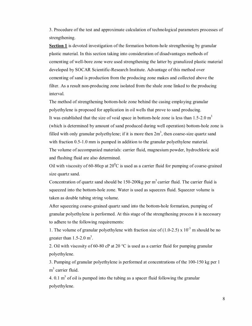
1. METHOD OF BOTTOM-HOLE FORMATION STRENGTHENING BY
GRANULAR PLASTIC
Having some disadvantages methods of astringent or cementing of wellbore zone were used
in the strengthening methods worked by “SOCAR Scientific-Research Institute” specialists to
some degree.
In the given systematical job instead of astringent or cementing material recommended
granulized plastic material – polyethylene with high pressure. Polyethylene has less specific
weight comparing to astringent or cementing material and occupies the same volume of
damaged zone. Heat effect of the high heat capacity material (heated vapor, exothermal
reaction, electrical heating etc) within 398-423 K agglomerates plastic granules with each
other and with sand and as a result very high permeable and strong barrier created. This
barrier supports further operation of the producing zone.
Advantage of this method over cementing of sand is shown below (figure 1.1).
a) Cemented Sand and other method b) Granulized polyethylene
Figure 1.1 Wellbore schematic post strengthening
13
5
2
7
6
4
13
5
2
7
6
4
88

13
1 Production casing
2 Filter or perforation
3 Producing zone
4 Non producing zone
5 Shale zone
6 Cement or astringent material
7 Producing zone fluid
As it is visible on the picture above (figure 1.1 a) sand production from the procuring zone
makes and collected above the filter. As a result non producing zone isolated from the shale
zone linked to the producing interval. As cementing material injected via the screens pushes
reservoir fluid from the wellbore into the reservoir and collected on the top of the screens.
Following that to cover hole interval with cementing (strengthening material) is not possible.
However if granulized polyethylene injected to such well (figure 1.1 b) all interval covered
with strengthening material.
1.1 Experimental study of strengthening material
1.1.1. Study of filtration and strength characteristics of material
Experiment carried out under required conditions to melt the granules in the unit shown in
figure 1.2 and following the below sequence.
Reservoir model 6 filled with granulized polyethylene (granular size of 1.5-2.5x10^-3m),
installed in the chamber and linked by the tubes from the vacuum pumps and heat exchangers.
Temperature in the chamber is equal to the reservoir temperature. As vacuum created in the
reservoir model while valves 1, 7 are closed and 2, 3 are open. After this, valves 7, 11 opened
up and reservoir model saturated with water or oil from the vessel 10 while valves 12, 18 and
19. Then from the vessel 17 water pumped 16 to thermostat 15 where heated up to 373K and
passing through the muffle furnace 14 changes to vapor. Heated vapor directed to the

14
reservoir model 6 with opened valves 1, 3, 7, 12 and closed valves 2, 11, 18, 19. Vapor rate
and pressure controlled by valve 3.
For exothermal reaction as a heat source used reactor 20 which is filled with magnesium.
From the pressurized vessel 22 through the filter 21 under pressure of air from the balloon 23
to reactor flowed hydrochloric acid. This acid got in the reaction with magnesium and heated
up and then flowed into the reservoir model. During this operation, valves 1, 3, 7, 19 were
open and valves 2, 11, 12 and 18 left closed.
In order to get thermal effect from the reservoir model at the conducted experiment to the
mixture added Mg particles and HCl.
In all experiments agglomeration of examples granulized polyethylene and its mixture with
quartz sand conducted under temperatures of 398, 403, 413 and 423 K and for each
temperature levels permeability identified. Permeability and temperature dependence curve
built based on the experiments for the different polyethylene concentration with quartz sand
(shown figure 1.3).

15

16
Low temperature agglomeration envelope of polyethylene- 398-403K, where permeability
decreases as sand concentration increases in the mixture.
High temperature agglomeration envelope of polyethylene- 403-423K, where permeability
increases as sand concentration increases in the mixture.
However, at the second experiments permeability of the mixture increases up to the sand
permeability.

17

18
Reached examples have been tested on compession as a standard procedure. Test results
(Graph 1.4) shows that increase on agglomeration temperature also increases strength of
extrusion. For example at 402-423 °K temperature range strength of polyethylene is between
6.1 – 10.4 MPa. Increase of strength is seen on model which is made up mixture of
polyethylene granulation and high-silica sand. The strength of the mixture model with 30%
sand concentration at given high agglomeration temperatures are equal to 4.6 and 7.2 MPa.
Improvement in hardness of samples can be explained by increase in contact area between
polyethylene grains as a result of their softening under higher temperature. Increase in contact
area is the very reason of stronger fritting taking place between polyethylene granules and
grains of sand.
The fact that hardness of samples reduces with increasing sand concentration can also be
explained by changes in contact area between polyethylene granules. However, in this case
the area reduces since content of polyethylene itself is getting less with increasing sand
concentration. As a result, the hardness of samples containing 30 and 70% sand, at a fritting
temperature of 403 °K e.g. is 5.0 and 1.9 MPa respectively.
As was already mentioned above, fritting of polyethylene granules can be achieved utilizing
various sources of heat. Therefore, it was of practical interest to analyze the effect of different
conditions of fritting of polyethylene granules by various heat sources on hardness and
permeability of samples. For this purpose, in the experimental device described above (see
Figure 1.2), samples of granular polyethylene were obtained under influence of temperature
from overheated steam, exothermic reaction and electrical heater. Results of the analysis are
shown in Figure 1.5, which concludes that the hardness and permeability of samples do not
depend on the source of heat. In addition, polyethylene barriers obtained using all the types of
heat sources have permeability and hardess that ranges within (7.3-0.25) x 10-12 m2 and 5.2-
10.4 MPa respectively.

19
Figure 1.5

20
1.1.2. Determination of required thickness of the strengthening material.
The research work over determination of required thickness of granular polyethylene layer
behind screens taking into account the conditions that prevent silting of the produced barrier
was carried out in an experimental assembly, whose main element imitating a model of
bottom hole formation during setting is shown in Figure 1.6. Model consists of the following
elements: body 3, washers with port 7, metal screen 6 (mesh size 1 x 1 mm), manometer 2,
regulating valves 1, 8 and a vessel 9 for measuring fluid loss.
Scheme of the experimental assembly
Figure 1.6
21
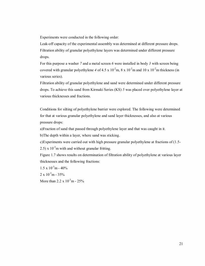
Experiments were conducted in the following order:
Leak-off capacity of the experimental assembly was determined at different pressure drops.
Filtration ability of granular polyethylene layers was determined under different pressure
drops.
For this purpose a washer 7 and a metal screen 6 were installed in body 3 with screen being
covered with granular polyethylene 4 of 4.5 x 10⁻²m, 8 x 10⁻²m and 10 x 10-2m thickness (in
various series).
Filtration ability of granular polyethylene and sand were determined under different pressure
drops. To achieve this sand from Kirmaki Series (KS) 5 was placed over polyethylene layer at
various thicknesses and fractions.
Conditions for silting of polyethylene barrier were explored. The following were determined
for that at various granular polyethylene and sand layer thicknesses, and also at various
pressure drops:
a)Fraction of sand that passed through polyethylene layer and that was caught in it.
b)The depth within a layer, where sand was sticking.
c)Experiments were carried out with high pressure granular polyethylene at fractions of (1.5-
2.5) x 10-3m with and without granular fritting.
Figure 1.7 shows results on determination of filtration ability of polyethylene at various layer
thicknesses and the following fractions:
1.5 x 10⁻³m - 40%
2 x 10⁻³m - 35%
More than 2.2 x 10⁻³m - 25%

22
Filtration ability of apparatus and layers of granular polyethylene
with various thicknesses
Industrial implementation of the method
Figure 1.7

23
As it’s shown in the figure 1.8, fluid loss through the layer decreases as thickness of granular
polyethylene increases provided all the other conditions are same. For example, at 0.012 MPa
pressure drop the fluid loss through the layers with thickness of 4.5 x 10⁻²m, 8 x 10⁻²m and 10
x 10-2m was 10.8, 8.3 and 7.2 x 10⁻⁵ m3/sec, respectively. Figure 1.8 presents results of
analysis on filtration ability of polyethylene and sand with various thicknesses, which shows
that the greater the thickness of sand over granular polyethylene, the lower the fluid loss.
Layers of polyethylene and sand were used to reveal the conditions of polyethylene barrier
silting. For this purpose, fluid was allowed to filtrate through layer of various thicknesses at
different and constant pressure drops during reasonably long period of time.
Filtration ability of granular polyethylene and sand layers
Figure 1.8
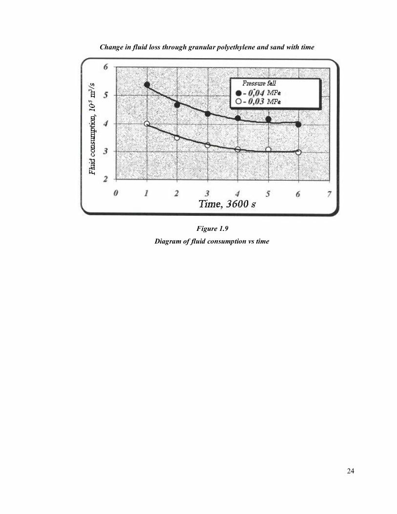
As an example, Figure 1.9 shows results of fluid filtration through layers of polyethylene
hpe=10 x 10-2m and sand hsand=6 x 10⁻²m at two different constant pressure drops, ∆P=0.03
MPa and ∆P=0.04 MPa.
24
Change in fluid loss through granular polyethylene and sand with time
Figure 1.9
Diagram of fluid consumption vs time

25
As can be seen from the figure 1.9, after a period of about (4.5-5) x 3600 sec from the start of
the experiment it was observed that fluid loss was reducing at both pressure drops. During
about the same period of time sand exclusion was taking place at following fractions:
0.25 x 10⁻³m - 0
0.1 x 10⁻³m - 3.15%
0.05 x 10⁻³m - 42.8%
0.05 x 10⁻³ - 0.01 x 10⁻³m - 28.45%
Less than 0.01 x 10⁻³m - 25.6%
Henceforth, fluid loss got stabilized at a certain level and remained unchanged till the end of
the experiment; however, sand exclusion had stopped.
Analogues results were obtained for polyethylene and sand layers of other thicknesses as well.
In addition, after each experiment the apparatus was disassembled, first of all the whole layer
of sand was removed, and then polyethylene was extracted gradually at thin layers. This
layerwise removal of polyethylene allowed us to determine the thickness of the last thin layer,
pores of which was filled with sand. Results of experiments with polyethylene and sand layers
respective thicknesses of which were hpe=10 x 10-2m and hsand=6 x 10⁻²m showed that the
depth of sand invasion was 2 x 10⁻² (though few sand particles were observed at 3 x 10⁻²m),
and the size of that fraction of sand that invaded pores between polyethylene granules was
more than 0.1 x 10⁻³m.
Experiments with various polyethylene and sand thicknesses showed that in all cases fluid
loss was getting reduced after prolonged filtration through polyethylene due to sand particles
blocking the pore space between granules. Moreover, with increasing sand thickness above
granular polyethylene sand exclusion and its depth of invasion into polyethylene was getting
reduced.
Experiments also showed that sand particles with size of 01 x 10-3 - 0.05 x 10⁻³m and less
must be excluded; otherwise silting of granular polyethylene will take place. With regard to
this it was established that to provide exclusion of sand with sizes mentioned above, the
thickness of polyethylene must be not more than 5 x 10⁻²m.
1.2. Industrial implementation of the method
The method of strengthening bottom hole formation behind production casing employing
granular polyethylene is proposed for application in oil wells that prone to sand production,

26
which are produced by natural flow, compressed air and bottomhole pumping, and at
temperatures below 373 °K. The method can be successfully used in wells with high reservoir
pressure and production rates as well as low pressure and rates.
The process of strengthening of bottom hole formation consists of the following stages:
Wellbore preparation;
Filling the bottom hole formation with strengthening material;
Fritting of granular polyethylene.
Wellbore preparation for strengthening includes the following successive operations:
Lower completion is pulled, well bottom is inspected and the fluid level is determined;
Production casing is inspected by means of sweeping-up;
Tubing string of corresponding diameter is run up to top of screens;
If sand bridge/fill exists, the well is cleaned-out to the bottom and then wash pipe is lifted to
top of screens;
For pumping granular polyethylene, wellhead is equipped with pumping head;
Formation intake ability is determined, which should not be less than 0.01 m3/sec at excessive
pressures, providing integrity of production string.
The size of void space in bottom hole formation is determined by amount of sand produced
during well operation, or other known methods; if it is less than 1.5-2.0 m3, bottom hole
formation is filled with only granular polyethylene, but if it is more than 2 m3 - then quartz
sand is pumped in addition to that;
The volumes of accompanied materials: carrier fluid, magnesium powder, hydrochloric acid
and flushing fluid are determined.
Filling the bottom hole formation with strengthening material consists of:
Pumping coarse-grained quartz sand if size of the annular void space is greater than 1.5-2.0
m3;
Pumping of granular polyethylene;
Granular polyethylene fritting.

27
1.2.1. Pumping of coarse-grained quartz sand
At this stage of the strengthening process it is necessary to adhere to the following
requirements:
The volume of coarse-grained sand with fraction size of (0.5-1.0) x 10-3 m should be 1.5-2.0
m3 less than the size of void space. If size of the void space in the bottom hole formation is
less than 1.5-2.0 m3, then coarse-grained sand is not pumped.
Oil with viscosity of 60-80 cP at 20 °C is used as a carrier fluid for pumping coarse-grained
sand.
Concentration of the coarse-grained quartz sand should be 150-200 kg per 1 m3 carrier fluid.
Coarse-grained sand with carrier fluid is squeezed into the bottom hole formation by
squeezing fluid - water. The volume of squeezing fluid is taken as double tubing string
volume. During squeezing the wellhead pressure must not exceed the pressure ensuring
integrity of tubing string and production casing.
To determine the potential case of sand settling and partially covering screens, once squeezing
has finished the bottom hole is checked by running additional tubing joints. Should sand
bridges exist, the sand cleanout is performed.
1.2.2. Pumping of granular polyethylene
After squeezing coarse-grained quartz sand into the bottom hole formation, pumping of
granular polyethylene is performed. At this stage of the strengthening process it is necessary
to adhere to the following requirements:
The volume of granular polyethylene with fraction size of (1.0-2.5) x 10-3 m should be no
greater than 1.5-2.0 m3.
Oil with viscosity of 60-80 cP at 20 °C is used as a carrier fluid for pumping granular
polyethylene.
Pumping of granular polyethylene is performed at concentration of the 100-150 kg per 1 m3
carrier fluid.
0.1 m3 of oil is pumped into the tubing as a spacer fluid following the granular polyethylene.

28
Granular polyethylene and spacer fluid are squeezed into the bottom hole by water. The
volume of the squeezing fluid is selected to be such that to squeeze spacer and carrier fluids to
the distance of 0.3-0.5 m from the bottom hole formation.
This volume of squeezing fluid is the sum of tubing string capacity, volume of screens and
pore space at radius of 0.3-0.5 m.
Filling of bottom hole formation with strengthening material is carried out with the help of
technology, specified in Table 1.1, pipe hookup for which is shown on Picture 1.10.
Table 1.1
Required amount of equipment during process of bottom hole zone strengthening
Technical means
Units Sand-oil blender ЗПА tank lorry
Number 2 1 1 1
1.2.3. Fritting of granular polyethylene
As already mentioned above, fritting of granular polyethylene can be achieved using various
heat sources. Described below is the process of fritting by exothermic reaction in the
formation and overheated steam.
1.2.3.1. Utilization of an exothermic reaction
In this case the process of fritting is conducted as follows:
Magnesium powder of brand MPF-2, which is taken at 7-8 kg per 1 m effective capacity of
screens pumped into the bottom hole formation;
Starch solution is used as a carrier fluid for magnesium powder. It contains:
Industrial starch - 2%
Caustic soda - 2%
Water - 96%

29
One litre of starch solution should contain 100-150 gr of magnesium powder;
Following the magnesium powder, 15% hydrochloric acid is pumped into the bottom hole
formation, separated by 0.2 m3 spacer fluid (2% starch solution). The volume of hydrochloric
acid is taken as 20-25 kg per 1 kg of magnesium;
Pumping of 15% of hydrochloric acid is carried out at first speed of the unit and is squeezed
by squeezing fluid - water, volume of which is the sum of tubing and screen volume.
Squeezing fluid is separated from the acid by spacer fluid, 0.2 m3 of oil;
After acid squeezing is finished, valve at the wellhead is closed and the well is left for 24
hours to allow complete fritting of polyethylene and temperature to decrease to formation
temperature;
Schematic of pipe hook-up to perform strengthening of bottom hole zone by granular
polyethylene
Figure 1.10

30
Pumping head is disassembled and the well is washed down to bottom by connecting
additional tubing joints;
Tubing string is pulled out of hole, lower completion is lowered;
The well is put on production by applying gradual increase in drawdown.
1.2.3.2. Pumping of overheated steam
After squeezing granular polyethylene into the bottom hole zone:
Pumping head is disassembled and in order to avoid granular polyethylene accumulation in
the annulus, water is pumped into the well by lowering tubing string to the bottom of the well;
Tubing string is pulled to the middle of screens and equipment for pumping overheated steam
is installed on the wellhead;
Overheated steam is pumped into the well through tubing string to achieve temperature
necessary for fritting in the bottom hole formation zone at radius of 0.5m;
The required steam temperature at wellhead to achieve fritting temperature at the bottom of
the well is determined by the following formula:
where,
T - temperature at wellhead, °C;
Θ - average temperature at external surface of the casing, °C;
To - temperature necessary for polyethylene fritting,
To = 125-150 °C;
K - coefficient of heat exchange through the casing wall and cement, k=10 kcal/m2 x hour x
x°C;
D - well diameter;
L - well depth;
Cp - steam heat capacity at constant pressure (average along the well, Cp = 1.5 kcal/kg x x°C;
G - Steam pump rate, kg/hour.

31
Time required to get bottom hole zone at radius of R=0.5 m to required temperature is
determined by the formula:
where,
= dimensionless variable coefficient;
Cn = heat capacity of polyethylene at high pressure, Cn = 1.5 kcal/kg x °C;
ρn = density of polyethylene at high pressure, ρn = 920 kg/m3;
m - porosity of granular polyethylene of utilized fraction size, m = 0.4;
L - coefficient of heat exchange of steam, L = 50 kcal/m2 x hour x °C;
- specific surface area of polyethylene granules, = 3000 m2/m3;
V - Void space of bottom hole zone, filled with polyethylene granules, m3;
Q - steam pump rate, m3/hour;
Dimensionless coefficient is determined by the formula:
where - dimensionless variable coefficient determined by:
After finishing pumping steam, wellhead is closed and the well is left for 24 hours to allow
complete fritting of polyethylene and temperature to decrease to formation temperature;
Wellhead is disassembled and the well is cleaned to bottom through the tubing string;
Tubing string is pulled and the lower completion is installed;
The well is put on production by gradual increase in drawdown.

32
2. METHOD OF BOTTOM HOLE STRENGTHENING OF WELLS WITH
PERFORMATIONS IN UNSETTLED CEMENT SLURRY
The below described casing method is offered by experts of SOCAR Scientific-Research
Institute and preconditions underlie its development. The main shortcoming of the earlier
offered casing methods was the fact that along with the productivity slowdown of a well, in
some cases there was observed renewing of sanding, with even greater intensity. Renewal of
sand production after the carried out casing is explained by the specificity of cement stone
perforation, in the production process of which a part of projectiles remain in layer of a
cement stone, and the other, with the influence on a productive layer, destroys it, forming new
caverns. In addition, detonation of a punch charge in a cement stone and on the contact of a
cement stone with a column causes the formation of crackss and channels.
The casing method of bottom-hole formation zones include filling of cement mortar to well,
squeezing it into a layer by means of viscous-plastic fluid and perforation of producing
interval which is offered to be produced till the curing of cement mortar.
Availability viscous-plastic fluid as a buffer element prevents dilution of cement mortar with
squeezing liquid (process water) and provides fixation of punched channels in a hardening
solution.
At the moment of punching the flushing fluid (that is not in perforation channels as they have
not been created yet) is pushed aside by pressure of gases both from grouting solution and in
it At the moment of rupture of charge of gunpowder separation of flushing fluid takes place
(not losing the viscous-plasctic properties) to the border with the solution and in channels At
the appearance of channels the flushing fluid occupies a cavity of channels before they start to
deform under weight of abovementioned rocks and cement that is caused by the fact that
cement forcedly passes to the solid state, and hydrostatic column of the liquid in the well is
prevents efflux of flushing fluid.
Pressure of the initiated blast wave at the perforation not hardened cement mortar causes
better penetration of the latter into cracks and caverns, increase of contact bond grouting
material with the layer rock. Considerably directed pressure difference, formed at combustion
of a powder charge of punched projectiles, creates conditions for consolidation of grouting
solution and separation of excess water that provides formation of a cement stone with high
strength and optimum filtration indicators.

33
Explosive character of pressure rise considerably reduces terms setting (hardening) of
grouting solution, and in the presence of calcium chloride in 1-6 % amount leads to a forced
passing of a solution to solid state.
2.1. Laboratory studies
The following conditions underlie experimental setup for the study of a punching mechanism
in not hardened solution:
provision of contact of cement mortar with rock,
Carrying out of control measurings of the perforation channel.
Determination of strength characteristics of grouting solution subjected to explosive
influence;
Visual research of the punched channel.
The basic element of the experimental setup, combined target, was a connection of three units.
The first unit contained a shooting device 6 concluded in the case 5
The second unit has been presented by the punched casing 9 in which there was a thin-walled
aluminium sleeve 4 with a cement mortal 3. Space between a sleeve and the case was filled
with paraffin for creation of plastic deformation conditions of the case of a sleeve during
shooting. The upper part of a sleeve was blocked by a metal disk 8, and the space under the
bottom cut of the shooting device was filled with the flushing fluid 7 having viscous plastic
properties.
The third unit also consisted of the punched casing with a set of the plastic rings 10 placed
inside, with 0,1 mm interring gap for the takeout of combustion products. Sample of the rock
preliminary saturated with decontaminated oil, which contacted with environment through
interring gaps was also placed here.
The installation set consisted of standard ultrathermostat ТС-24, a shooting device and test
instrument, shown on the figure.
The cement mortars, mixed with soft water, with the various water cement factor and
additions of the setting accelerators of solution, calcium chloride (СаСl) were prepared.
The investigated cement mortal was filled in a sleeve which was placed in thermostat. After
certain time a sleeve was taken from the thermostat and placed in the combined target. After
shooting of the target, the taken sleeve together with the cement sample was cut in

34
asymmetric direction along the formed punched channel, for its visual examination and
measurement.
It should be noted that though the conducted experiments did not modeled real layer
conditions completely, they made it possible to give comparative assessment of the size and
stability of walls of the punched channel.
2.1.1. Study of the factors affecting physical characteristics of strengthening material
2.1.1.1. Effect of water tempering
During the process of casing under field conditions, fresh water can be not always used. So,
under the conditions of the land of Azerbaijan, usually for mixing if cement mortars layer
water is used, and in sea deposits – sea water is used. In connection with the mentioned, for
the determination of a change rate of physical characteristics of the casing composition
subject to the properties of water used for its mixing, studies were carried out with three types
of waters.
During the studies soft water of Shollar spring, produced water of Umbaki deposit
(Chockrack horizon) and water of the Caspian sea were used. The content of waters and some
of their characteristics are given in the Table 2.1.
Experiments were carried out at 293 oK temperature, strength characteristic were taken
24x3600 seconds after the beginning of hardening of a cement mortar. Results of the
experiments are given in the Table 2.2

35
Table 2.1
Composition of waters used during laboratory examination of the process of cement mortar
mixing
Name of the water Soft Produced Sea Density, kg/m3 1001,1 10)2.2 1009,4 Dense residue at 180 0С, % 0,0290 1,4121 1,3244
Na’ + K’ 10,0 241,0 139,0 Са" 20,0 0,06 20,0 Mg" 20,0 5,9 58,0 Cl’ - 165,2 154,0 SO4’ 10,0 7,8 61,0 HCO3’ 40,0 36,7 4,0 CO3 - 34,0 - OK - 0,19 -
Composition of
water,
mg.eq|l
HBrO2 0,19 -
Table 2.2
Influence of the composition of water on the characteristics of casing material
Physical characteristic of the mortar and cement stone
Setting time, hour-min Name of
water
Den
sity
, kg/
m3
Flow
ing,
10-2
m
Initial Final
Ben
ding
stre
ngth
,
MPa
Soft 1830 22.5 4-50 5 - 55 1,82 Produced 1800 18,0 4-25 5-55 2,00 Sea 1830 20.0 4-00 4- 55 2,20
As is seen on the table, while using fresh and produced waters indicators of hardening times
of solutions and strength characteristics actually coincide. Strength characteristics of the
solution mixed with sea water, actually does not differ from the solutions prepared with the
use of above mentioned waters. However great difference of setting times is observed. So, if
the initial setting time differs for 25 and 50x60 seconds from this indicator for the solutions

36
mixed, accordingly, with produced and fresh waters, then the final setting time already differs
for 3600 seconds. The fact, undoubtedly shall be taken into consideration during the planning
of technological process of casing in each concrete well.
2.1.1.2. Effect of temperature regime and the content
of calcium chloride in cement slurry.
Investigations of these factors were carried out respectively within the ranges 285-323oK and
1,0 – 6,0 %. Based on the procession of the investigation results, dependencies of mechanical
strength of cement stone samples, tested for bending were built from each analyzed parameter
on the fixed value of the other. Thus, on the Figure 2.1 change of the mechanical strength
subject to the content of calcium in the sample at 293 oK is shown.
As is seen on the figure, the samples acquires the intense set of strength on the content of
calcium chloride up to 4%. On the increase of the content of CaCl2 in the cement sample the
change curve tends to flatting.
On the Figure 2.2 the dependence of the strength of the cement sample on the temperature
when the calcium chloride content is equal to 3% is given:
As is seen on the figure, temperature factor has significant influence on the strength indicators
of the samples. Thus, on the change of temperature from 285 to 323 oK strength of the cement
stone with the given content of CaCl2 increases almost 2,5 times.

37

38

39
2.1.1.3. Determination of the maximum depth of the perforation channel.
Series of experiments carried out to determine maximum depth of the perforated channel with
the strength indicators of cement mortar equal to 1,3 MPa or higher, allowed us to detect
limits and application field of the method. The limits were established based on the ensured
opportunity of maintenance of the perforation channel with the availability of viscoplastic
fluid. After the establishment of maximum allowed characteristic of the cement mortar,
further experiments were carried out with the second block of the above described.
Perforation channels, formed before and after the hardening of the cement mortar 4,5 x 3600
seconds after its hardening at 293oK temperature, are shown on the Figure 2.3 (a & b).
Based on the results of experimental investigations, dependences of the change of perforated
channel from the strength characteristics of the hardening cement mortar are shown on the
Figure 2.4. It shall be noted that dependencies are given for two categories of wells: uncased
(open surface of the sample) and with casing pipe (presence of metal disc). Moreover, given
the condition that physical characteristics of the cement mortar may change in quite wide
ranges (subject to the batch of cement and storage conditions), on the building of dependences
relative depth values of the perforated channel Z/Z and strength / were used.
The analysis of dependences shows that in the area of high values of strength indicators of the
cement sheath the influence of casing pipes on the depth of perforated channel is insignificant.
When / < 0,1 the influence of the wall of the casing tube increases significantly. Thus,
when / = 0,1, size of the channel in the absence of metal obstruction may increase 2 times,
and in comparison with minimal value of 1 10 times.

40

41
2.2. Industrial introduction of the method
Technological process of the fixing of the bottomhole zone of the layer is carried out with
standard equipment and consists of the following:
Cement mortar is prepared in mixing machine and loaded by the filling unit to the bottomhole
zone of the cased well, in accordance with the scheme shown in the Figure 2.5;
Following the cement mortar well is filled with flushing viscoplastic fluid, structural and
mechanical properties of which are given on the Table 2.2 and then again process water;
Table 2.3
Investigation
temperature, oK
Density, kg/m3 Structural viscocity,
MPa x s
Ultimate shearing
stress, Pa
293 874 220.0 1,2
313 860 180,9 1,0
After the squeeze of cement mortar with viscoplastic fluid into the bottomhole zone of the
layer, perforator is landed into the well, and during the period from the initial setting to the
hardening of the mortar, perforation of the producing interval is carried out.
After the completion of perforation and lifting of the perforator from the well, it is placed in
operation by the method of gradual launching.
Weight of the loaded grouting mortar, flushing fluid and process water, as well as parameters
of the perforator are determined by typical design method subject to the state of the tube and
bottom of the well, strength of the cased layer and its absorbing capacity.
Content of calcium chloride in the mortar (CaCl2) is regulated subject to the depth of the
pbject and temperature of the medium. Thus, the Table 2.4 shows the influence of the
temperature on the setting time of the cement mortar with 1930 kg/m3 density on the
boundary values of the content of calcium chloride.

42
Table 2.4.
Setting time of the cement mortar at bottomhole temperatures and contents of CaCl2
Setting time of the mortar in minutes after the preparation, with the
content of CaCl2
1% 6%
Temperature in
the bottomhole, oK
initial final initial final
293 306 380 155 210
323 120 160 55 85
As is seen on the table initial setting time of the cement mortar under the given conditions
rages between (55-306)/60 seconds. Given the time intervals of the setting of the mortar and
by comparing them with the total time, spent to all the operations, connected with the
production of final casing works (washout of the excess cement mortar, lifting of filling pipes
from the well, perforation works and final operations) necessary concentration of CaCl2 is
selected.

43
Schedule of the bottomhole zone
1 – production layer; 2- flow string;
3 – perforation holes; 4 - oil-well tubing;
5 – cement mortar; 6 - flushing fluid;
7 - cement sheath
Figure 2.5
2.2.1. Efficiency of the method
The efficiency of the described casing method will be demonstrated based on the comparative
analysis of the work of one of the desanding units of the Balakhany-Sabunchu-Ramana
deposits, bottomhole of which earlier was subjected to casing with cement mortar, and use of
the available interval of the filter after complete hardening of the mortar.

44
Well No. 3492 used productive horizon of Kirmakin suite (IKC2) with the filter in the interval
1244-1250 m? and was equipped with 168x10-3 m operation tube with artificial bottom-hole
1272 m.
The well was introduced from the return and within 3 months of the work reduced the output
from 2,9 to 0,4 – 0,7 m3/days. Watering of production raised from 40 to 90% with 1.4% of
layer sand. overhaul period of work of the well also was reduced to 10-15 days.
For the struggle with sanding in the well casing with cement mortar by a standard technology
at 10 MPa excess pressure in the mouth with washout of the excesses of cement before
bottom-hole (1272m) was carried out.
After casing with standard technology the well entered the operation with unchanged average
indicators of oil withdrawal, water and overhaul period witnessing the non-efficiency of the
taken measure.
6 months after the return to IKC2 works on the casing of bottom-hole zone of the well by the
offered method were carried out.
3,0 m3 of cement mortar of 0,5 water-cement ratio was prepared with adding of calcium
chloride in the amount of 1% of the weight of dry cement that was loaded at 10 MPa excess
pressure in the well head. Loading to the bottom-hole zone was carried out through 73 mm
NKT and hole of the corresponding filter with further washout of mortar residues up to the
bottom-hole. Then, bottom-hole was filled with flushing viscoplastic fluid (kirmakin mud oil,
characteristics of which are given on the Table 2.3) and 5 hours later shooting of filter with
cumulative perforator PK-80 was carried out.
Total time spent to all the operations connected to the production of concluding casing works
(washout of the excesses of cement mortar, lifting of filling pipes from wells, perforation
works and concluding operations), makes on the average 1x3600 seconds for 300 m of the
depth of the well.
For the implementation of the above listed operations took about 5x3600 seconds. By that
time with 1% concentration of CaCl2 and at 303 oK temperature in the bottom-hole setting
process of the cement mortar had not stopped.
On concrete practical example of the Well No 3492 the time required for all the casing works
is determined by the division of the well H=1272 m by normative indicator h/t=300 m/3600
sec, that is,

45
H 1272 m
h 300 m
t 3600 sec
It shall be noted that cement mortar has not yet turned into solid. Final setting of the mortar
occurred during the following 55 x 60 seconds. Thus, completion of the setting of the mortar
occurred 4,24 x 3600 + 55 x 60 = 5,16 x 3600 seconds later.
This calculation shows that there were optimal conditions for the creation deep and stable
perforation channels in the layer that at the moment of dynamic influence keep their
configuration. The depth of the perforation channel with the hardened cement stone Z1 and the
depth of the channel with non-hardened cement mortar Z2 can be detemined by the following
formula:
Z1=Z2
(2.1),
Where 1 – density of the cement stone 1810 kg/m3;
2 – density of the cement stone 1815 kg/m3;
- coefficient considering the influence of environment, taken as equal to 1;
1 – ultimate tense of the cement mortar at 20 MPa compression;
2 – ultimate tense of the cement mortar at 0,4 MPa;
Bu using (3.1) to determine how many times N the data of the channel by the developed
method is more than the length of the channel we get:
N=
(2.2),
We put the known values into (2.2) and get N=7.
t = = = 4,24 x 3600 sec
1 1
2 2
1 1
2 2

46
Thus, 7 times increase of the length of the perforation channel made it possible to increase the
perfection of the inflow of fluid into well and get stable fluid samples with lower pressure
gradient, ensuring safety of the layer skeleton.
After the development, the well was set into operation by mechanized method (NSB-1), by
the method of gradual increase of depression on layer with gradually increasing output from
0,7 to 2,8 m3/day of oil and reduction of watering from 90 to 45%. Within six months the well
worked without repairs, that further led to the reduction of the solid phase from 0,2 to 0,04%.
Data obtained from the application of this method of casing of bottomhole zone of sanding
wells, show that due to the exclusion (in a certain period of time) of sanding, need for
underground repairs connected to the liquidation of bottomhole plug, actually falls away, oil
output, and significant reduction of the water inflow excludes additional operation on the
production of repair and insulation works.
3.METHOD OF BOTTOM HOLE STRENGTHENİNG ACİD-OİL BASED CEMENT
SLURRY
The method was worked out in SRI SOCAR oil and consists of the filling of layer with
grouting mortar, made by mixing of dry Portland cement with weak concentrated aqueous
solution of hydrochloric acid. Concentration of the aqueous solution of hydrochloric acid
ranges between 6-8%. For the formation of additional pores, regulation of setting time and
slowdown of chemical reaction between particles of cement and hydrochloric acid the system
is added crude oil in the amount of up to 6% of the weight of dry cement.
As a result of mixing of fine-grain minerals of cement clinker with hydrochloric acid
hydration and hydrolytic dissociation reactions leading to the formation of strong and
permeable stony concrete take place.
In the offered method obtainment of a permeable barrier is achieved by the availability of
cement, lime, carbonate, silica, alumina, magnesium, aluminum, iron and many other
components in the content, some of the easily react with hydrochloric acid. In the process of
filling interaction with gas emission and formation of additional pores in the created barrier
takes place in the borehole and bottomhole zone of the layer. Completed “Aerated” solution
in the bottomhole zone gradually sets and forms stable, full-strength and isotopic-permeable
barrier.

47
3.1. Laboratory study of strengthening material
Test-pieces with various component contents, filtration and mechanical characteristics of
which were determined, were prepared in laboratory conditions. The preparation and
hardening process of mixtures was carried out under the conditions close to layer ones.
The major part of experiments was conducted with the curing of samples under atmospheric
pressure and at room temperature.
3.1.1. Effect of hydrochloric acid concentration on characteristics of filtration and strength of
cement
Investigations of filtration and strength characteristics of samples of cement stone, made from
various concentrations of hydrochloric acid, were carried out on the laboratory facility, shown
on the Figure 3.1. consisting of core holder 1, vacuum pump 2, tee 3, manometer 4, funnel 5
for loading of the container 7, lines of resultant pressure 6, pressure release valves 8, pressure
regulator 9, filter 10 and balloon with compressed nitrogen 11. Samples were saturated with
fluid. Measuring of fluid flow was carried out with the established regime of pressure fall
through regulation. Investigations were carried out at room temperature without taking into
consideration overburden pressure.
Results of the of investigations on learning of filtration properties, are given on the Figure 3.2
in the from of curves of dependency of permeability on the concentration of hydrochloric
acid.

48
Sche
me
of e
xper
imen
tal u
nit
Figu
re 3
.1

49
As is seen on the figure, increase of permeability of samples with the increase of the
concentration of aqueous solution of hydrochloric acid is observed. Thus, if at 5%
concentration of hydrochloric acid permeability is 25 x 10 -15 m2, then at 9% concentration it
reached 117 x 10-15 m2. Increase of the concentration of hydrochloric acid more than 11%
leads to the formation of filtration channels and washout of samples.
Investigations showed that on the filtration of water through samples, permeability of the
latter tend to increase, and on the expiration of a certain period of time, begins to stabilize. It
is conditioned with the fact that on the filtration of water reaction products (CaCl2, MgCl2
etc.) dissolve and are taken out of pore space.
It should be noted that, as a matter of fact, permeability of a cement mortar will not differ
from the obtained results, as under natural conditions during the work of well uninterrupted
process of filtration, followed by microcolmation and boil takes place.
Results of testing of sample for destruction at uniaxial compression in the “2ПГ – 10”
laboratory press are shown on the Figure 3.2. As is seen on the Figure, the dependence of the
strength of the sample on the concentration of aqueous solution of hydrochloric acid has a
quite difficult character. With the increase of the concentration of hydrochloric acid up to 8%,
strength gradually increases and becomes 6,6 MPa. Further increase of concentration of
hydrochloric acid leads to rapid reduction of sample strength and with 12% aqueous solution
the mixture does not set at all. Such character of strength change can be explained by the fact
that, as it was mentioned above, dry Portland cement consists of fillers (e.g. carbonate), which
on the usual preparation of cement mortar reduce strength of cement stone /11,12/. On the
preparation of the solution in the examined case, some of the mentioned filler react with
hydrochloric acid. Increase of the temperature, as a result exothermic reaction, conditions
increase of the strength of cement mortar. Thus, hydrochloric acid with the noted
concentration up to 8% proves as catalyst, favoring acceleration of the process of
strengthening.

50
Strength degradation of the cement stone made from aqueous hydrochloric acid solution with
more than 8% concentration is explained by the fact that the components of cement that
provide strength (Al, Mg etc. compounds) on concentrations lower than 8% begin to undergo
chemical reactions.
During the designing of a fastening process, time factor gains decisive importance, especially,
when process is connected with the application of fast-setting composition. In connection
with the noted, influence of concentration of hydrochloric acid on setting time of cement
mortar results of which are given in the Figure 3.3. As follows from the figure, as the
concentration of hydrochloric acid increases from 5 % to 8 %, initial setting time increases
from 35x60 to 55x60 seconds.

51
3.1.2. Effect of hydrocarbon additives on characteristics of filtration and strength of cement
Loading of a hydrocarbon phase into cement mortal as an additive was caused by the
following:
Necessity of inhibition of chemical reaction between cement and a aqueous solution of
hydrochloric acid to form additional pores;
Necessity of obtainment of mobile mass: grouting mortar shall be mobile on pumping into
well and its driving through annular space;
Regulation of setting time: after adding of fastening to the object it is necessary to make
cement harden as soon as possible.
Experiences for determination of the influence of percentage of oil on spreadability of
grouting mortar determining its mobility, was conducted on the cone of "АzRI" (Azerbaijan
Research Institute) by a standard technique designed for cement mortars. Cement mortars shut
on acid-oil emulsion with from 2 to 10 % content of viscous oil of Kirmakinsky measure.
On the basis of the investigation of the samples made at various concentrations of
hydrochloric acid and oil, it was revealed, that irrespective of hydrochloric acid concentration,
with increase of percentage of an oil phase, permeability of the sample of a cement stone
increases. According to the investigation results, dependences of the change of the sample
permeability on concentration of hydrochloric acid at various percentage of oil in cement
mortar presented in the Figure 3.4 were built.

52

53

54
As follows from the figure, permeability of cement stone depends both on concentration of
hydrochloric acid, and quantity of hydrocarbon phase. So, permeability of cement mortar made
from 5% hydrochloric acid with addition of 2 to 10 % oil, increases from 27 х 10-15 to 44 х 10-15
m2, and from 9 % hydrochloric acid - from 122х 10-15 m2 to 217x10 -15 m2
The increase of the content of oil phase in cement mortar positively influences on setting time.
Change in the setting times of cement mortar subject to the content of oil phase and concentration
of a aqueous solution of hydrochloric acid is shown on the Figures 3.5 and 3.6
From the Figure 3.5 it follows that on the addition of 2 % oil phase to cement mortar prepared
from 5 % hydrochloric acid, the initial setting time comes in 40x60 seconds. Addition of the
same amount of oil to cement mortar shut on 11 % hydrochloric acid, leads to its setting in about
5x3600 seconds. The end of the setting of these cement mortars, is respectively equal to 2x3600
and 48,5x3600 seconds (Figure 3.6). Adding of 8 % oil to the solution made from 11 %
hydrochloric acid, leads to a friable condition of the sample and the cement mortar practically
does not set.
3.1.3. Effect of temperature on hydration of cement slurry
It is known, that initial and final setting time of the mix is reduced with increase of the ambient
temperature. On the other hand, availability of liquid hydrocarbon phase slows down hydration
process, and initial and final setting time increase as oil by creating "cover" on waterproof sites of
particles, being nonpolar liquid, leads to weakening of coagulation forces. In this connection
hydration processes of particles in initial hardening terms are slowed down and stone formation
(increase in durability of samples) actually does not occur at this time.
For the general picture of the phenomenon and concrete settlement sizes investigation of the
setting times of cement mortals, temperature-control of which was carried out at various
temperatures, with the use of the standard Vick device. Installation and experiment conditions
allowed to make measurements without taking samples from the thermostat.
It should be to noted that during the preparation of cement mortar from water with addition of
hydrochloric acid, chemical reaction and hydration occur at the same time. The reaction between
aqueous solution of hydrochloric acid and particles portland cement is exothermic as a result of

55
which heat release occurs with the increase in concentration of acid. If at 5 % acid the
temperature of the sample is 318oK, then at 12 % hydrochloric acid it reaches 363°К.
For approximation of the conditions of experiments to bedded, the investigated samples were
kept at various temperatures. Results of experiments are given on the Figure3.7.

56

57

58

59
It follows from the figure that in process of temperature increase, the initial and final setting of
cement mortal comes earlier. So, for cement mortal made from 7% hydrochloric acid and 4 %
hydrocarbon additive, at 293 °К temperature the final setting comes in 2x3600 seconds, and
at319 °К temperature -approximately 0,5x3600 seconds earlier. The similar phenomenon is
observed for the initial setting of cement mortar.
It is known that with the increase of the temperature setting time of cement mortar made from
water occurs under the curvilinear law. According to the results of the conducted experiments
it was revealed, that for cement mortar made from acid, the mentioned dependence is close to
the rectilinear.
It should be noted, that structure change grouting mortars at their movement in a way to the
planned interval of fastening has certain influence on setting times.
Action of preliminary mixing on structure formation a solution was considered earlier in / /
where researchers came to a conclusion, that preliminary mixing much more extends setting
time. Based on the conclusion, authors of the described way of fastening made an assumption,
that it is possible to line wells with about 1000 m depth, without being afraid of the premature
initial setting.
3.2. Commercial implementation of the method of strengthening
3.2.1. Application area of the method
For effective implementation of technological process of lining, the chosen sand-developing
wells shall meet following requirements:
Absence of demolition and column tap over all the period, including filtrationside area,
maximum volume of production in overfiltration zone not more than 4 m2
maximum depth of a well within 2500-3000 m,
minimum seam pressure 0,5 MPa;
maximum length of the filter within 25-30 m;
maximum admissible pressure difference 4,5 MPa;
maximum temperature around the lining area 355oK,
Maximum watering of the well production 90 %

60
3.2.2. Realization of technological process
Depending on a geological and engineering condition of a well, it is offered to carry out lining
of rocks in two variants:
In deep wells, with high seam pressure, low values of permeability and intake capacity,
pumping is carried out through lowered pump-compressor pipes;
In deep wells, with low seam pressure, high values of permeability and intake capacity
pumping grouting mortar is carried out through flow tubing.
Lining is made according to the scheme given in the Figure 3.8, in below order.
After washing of a sand plug, wash pipes 2 are raised and established 1,0-1,5 metres higher
the upper holes of the well filter.
The armature 3 gathers wellhead and incorporates to the land equipment by means of a
injection line 7,
Locking devices on the lines leading to annular and central spaces are locked, and by means of
the mobile pump unit 12 the ground-based equipment is molded to the pressure 20 MPa then
locking devicesa are unlocked.
Water is supplied from a water tank 8 by pump unit 9 to cement mixer 10, from where the
cement mortal moves to the tank// On preparation cement mortar water-cement solution is
taken equal to 0,4
At the same time cement mortar from the tank 11 by the unit 12, 15-17 % solution of
hydrochloric acid from the tank 14 by unit 13 and oil from the tank 15 by unit 16 are pumped
into the mixing device 5.
After the pumping of the grouting mortar in volume equal to volume HKI 2 annular space is
cut and all the designed (see the following paragraph) volume grouting mortar is pumped.

61
Layout of equipment during lining
Figure 3.8

62
Grouting mortar in the designed volume is pressed to the holebottom zone 1 by the unit 12 with a
liquid (water), then the locking device cuts the central space of the well.
control over the course of technological process of lining is carried out by a manometer 4, set on
the wellhead
On the completion of the lining process the well is left in a state of rest within 48 hours for
hardening the lining material
On the expiry of the setting time of cement mortar, the condition of the bottom hole is checked by
means of OWT(oil well tubing). If the filter is open, are lifted and the well is set in operation.
the well, bottomhole zone of which is characte OWT rised by the good absorbing capacity, the
above order of lining operations is carried through flow string.
3.3. Main performance indicators of bottom hole strengthening by acid-oil based cement slurry
The volume of lining material is taken equal to the volume of generation of a layer, that is
Vgen= Vlin
where Vgen – generation volume, m3
Vlin – lining material volume, m3
To determine the volume of generation of the layer, specific volume dependences of the produced
sand on object of work out (horizon, layer) from the work out time of the object can be used. A
number of such dependences for some horizons of the fields of Azerbaijan land presented on
Figure 3.9

63

64
Vgen= V1h (3.2)
where V1 – specific weight of the produced sand m3/m; h – effective length of the well m3
In connection with losses occurring during the technological process, the volume of lining
material shall be taken 20% more, that is:
Vlin= 1,2Vgen (3.3)
Volume of the lining material necessary for the lining of bottomhole formation zone is
determined by the following formula:
Vlin= 0,785[(D2gen -D2
e.fl.st)hk] (3.4)
where Dgen – diameter of generation or wells on plugged bit, m;
D2e.fl.st – external diameter of the flow string, m;
h – height of hole filter or generation formed behind the filter, m;
k – coefficient considering the losses of cement mortar is taken as ranging within k=1,01,3
Diameter of the formed generation is determined by the following formula:
Dgen= 1,273 + Dw (3.5)
Where Vs – volume of sand taken out during the washouts of sand plug for the period of
work of the well on one horizon, m3
Dw – diameter of the well on plugged bit, m.
V s
h

65
The quantity of dry cement, necessary for the preparation of cement mortar is determined by
the following formula
Qcem= Vlin (3.6)
Where Qcem – quantity of dry cement,t;
γcem – specific weight of dry cement, t/m3
γw – specific weight of water, t/m3
m - water-cement ratio, m=0,4-0,5
Volume of liquid, necessary for the preparation of grouting mortar is determined by the
following formula
Qliq= mQcem (3.7)
Volumes of water, oil and hydrochloric acid, necessary for the preparation of grouting
material are determined in the following way:
Qliq= Qw + Q’a + Qo (3.8)
Grouting mortar is made from 7,5% hydrochloric acid solution. In this connection to get
7,5% solution with the use of 22% hydrochloric acid (Q’a) the latter shall be taken 34%. That
is, to prepare 1m3 of 7,5% hydrochloric acid solution 0,66 m3 of water shall be added 0,34 m3
of 22% hydrochloric acid. Addition of4-6% oil to grouting mortar is 0,06 m3. Thus, total
volume of liquid in percentage will be:
Qliq= 60Qw + 34Q’a + 6Qo
γcemγw
γw+mγcem

66
or Qliq=94Qa + 6Qo
where Qa – 7,5% hydrochloric acid solution.
Volume of squeezing liquid, necessary for the squeezing of grouting mortar to bottomhole
formation zone is determined by the following formula
Qsq.liq= 0,785[d2idL + Dfl.st.in.d.. (h+h1) (3.9)
Where did = internal diameter of OWT , m;
L = landing depth of OWT, m;
h1 – distance between Т shoe and upper holes of filter, m
3.3.1. Rough estimate of main performance indicators of strengthening
Let’s suppose that the well, bottom-hole of which is designed for lining has the following
conditional parameters
Operated object - Underkirman Measure (PK)
Operation term - 5 years
Well depth, H - 958 m
External diameter of the flow string, De.d. - 0,168m
Internal diameter of the flow string, Did - 0,150m
Internal diameter OWT , did - 0,06m
Landing depth of OWT, L - 938 m
Filter depth, h - 13 m
Diameter of the formed generation, Dgen - 0,7 m
Specific weight of dry cement, γ - 1,02 t/m3
Water-cement ratio, m - 0,5
distance between OWT shoe and upper
holes of filter, h1 - 2 m

67
The volume of the generation formed in the bottomhole zone is determined by the formula(3.4)
Vlin= 0,785[(D2gen -D2
e.fl.st)hk]= 0,785[(0,72 -0,1682)x 13x1,2] = 0,785x0,46x15,6 = 5,6 m3
The volume of dry cement, necessary for th preparation of 5,6 m3 of grouting solution is determined by the formula (3,5)
Qcem= Vlin = Vlin x5,6 = 6.9
tons
Volume of liquid, necessary for the preparation of grouting mortar in volume
5,6m3 is determined by the formula (3,7)
Qliq= mQcem= 0,5x6,9=3.45 tons
Qliq=94Qcem= 6 Qo =3.45 tons
Qliq=345x =3.45 tons
Qo=345x = 0.2 tons
Thus, for the preparation of the grouting solution for the purpose of filling and lining
the generation formed in the bottomhole zone of well with 5,6 m3 volume, 6.9 tons of dry
cement, 3.25 tons of 7,5% hydrochloric acid and 0,2 tons of oil are required.
γcemγw
γw+mγcem
3,15x1,02
1,02+-,5x3,15
94
100
6
100

68
The volume of squeezing liquid, necessary for the squeezing of grouting mortar to bottomhole formation zone is determined by the following formula
Qsq.liq= 0,785[d2idL + Dfl.st.in.d.. (h+h1)] =
= 0,785 x [0,062x938+0,152x(13+2)]=
= 0,785 x (3,38+0,38)= 2,95 m3

69
CONCLUSION AND RECOMENDATİONS
The thesis includes introduction, three sections, conclusion and references.
In introduction actuality of the thesis, the object of the thesis, ways of solving of problems
and scientific novelty of dissertation were considered.
In oil fields where the rocks in the bottom-hole zones are unconsolidated more than 45% of
all subsurface maintenance time is spent in washing of bottom-hole zone or removing sand
plugs. At Apsheron peninsula oil fields 3000 wells out of 6756 producers had sand problems
and from 4000 well repairs carried out 1400 were related to the sand plugs.
Destruction of reservoir poorly cemented rocks and sand producing significantly complicates
wells operation process. Sand plugs are formed in wells borehole, well equipment is subject to
wear, hazard of formation rock fall accompanied by collapsing of casing and full breakdown
of well. One of the methods to prevent sand producing in wells is installation in the bottom-
hole zone slotted, gravel (packed), metal-ceramic well screens. But well screens are not
always reliable instrument of sand control. They are plugged with time, transmits part of the
small solid fractions. Therefore for strengthening of bottom-hole formation rocks chemical
methods are applied. With this purpose for treatment of loose sands organic resins and
polymers are used. Moreover, liquid agent (resin with hardening material) which after the
resin’s polymerization consolidates the sand grains, not changing significantly its filtrations
characteristics.
For this purpose such kind of mixtures are chosen that from which after polymerization the
specific amount resins, enough for sands hardening, but not plugging porous space of
formation, is obtained. Besides after injection of resin and activator into formation, for its
pressing in borehole inactive liquid is pumped.
In wells with strong destroyed rocks in bottom-hole, coursed sand and cement material
mixture, recovering crevices in formation and strengthening of them, injected at the same
time.
The third method consists in using such oil-lifting techniques and establishing such operating
conditions under which most of the sand entering the well is carried to the surface. This is
achieved by running small-diameter extensions to the bottom-hole, using hollow roads, fluid
injection, etc.
These methods greatly reduce the sand hazard but do not fully guarantee against plug
formation. It is periodically necessary to remove accumulated plugs. This may be done either

70
in the course of preventative maintenance carried out at intervals depending on the specific
conditions of well operation, or as an emergency in cases of major breakdowns.
Sand plugs are generally removed by blowing either by bailing or by jetting and circulating
out.
Occasionally sand plugs are removed by blowing them out with compressed air.
At present thesis to control sand-producing of wells strengthening bottom-hole zone rocks has
been chosen and in detail considered.
Three bottom-hole formation strengthening methods are investigated in this thesis:
1. Method of bottom-hole formation strengthening by granular plastic material;
2. Method of bottom-hole strengthening of wells with performance in unsettled cement slurry;
3. Method of bottom-hole strengthening acid-oil based cement slurry.
Order of implementation of the thesis is the following: experimental studies of strengthening
materials, production tests and procedure of the test and approximate calculation of
technological parameters processes of strengthening.
Studying all existing sand control methods we came to the conclusion that methods of well
bottom-hole strengthening have important advantages in comparison with others:
1. Bottom formation strengthening methods allows creating porous-permeable aggregate mass
in the bottom-hole zone.
2. Bottom formation strengthening methods prevents reservoir rocks from destruction and
loosening, and untimely water influx.
3. Bottom formation strengthening methods guarantee long duration stabil operation of oil
producers.

71
REFERENCES
1. Production Technology. Heriot- Watt University. Institute of Petroleum
Engineering. Author: Dr. David Davies. Edinburgh, 2004.
2. Penberthy W.L.,Shaughnessy C.M. Sand Control. SPE Series on Topics. Volume
1. Richardson: SPE, 1992. ISBN 1555630413.
3. Muravyov I.M., Andriasov R.S., Gimatudinov Sh. K., Govorova G.L., Polozkov
V.T. Development and Exploitation of Oil and Gas Fields. Peace Publishers.
Moscow. 1970. Pages 501.
4. Amelin I.D., Andriasov R.S., Gimatudinov Sh. K., Korotayev Y.P., Levikin E.V.,
Lutoshkin G.S. Ekspluatasiya i Tekhnologiya razrabotki neftyanix i gazovix
mestorojdeniy. Izdatelstvo "Nedra", Moscow, 1978. Pages 357.
5. Petroleum Engineering Handbook. Editot-in-Chief Howard B. Bradley. Third
Printing. SPE Richardson, TX, USA.
6. Maslov I.I., Skuinov B.A. Metodi Borbi s peskoproyavleniyami. Jurnal
Neftepromislovoe Delo I Transport, № 4. Moskow. 1985.
7. Баэиров вя б. Гум-су тязащцрлц гуйуларын гуйудиби ятрафынын
бяркидилмясинин йени технолоэийасы. Нефтчыхарманын техника вя
технолоэийасы. АЗНИПИнефт-ин топлусу. Баки, 1998.
8. Газлашмыш тампонаж мящлулу иля гуйудиби ятрафынын бяркидилмясинин
техноложи просесляринин апарылмасы цчцн тялимат. АЗНИПИнефт, Баки,
2005.
9. Мяммядов Т.М. Гуйудиби зонанын бяркидилмясинин сямярялилийинин
артырылмасы цчцн йени технолоэийанын ишлянилмяси вя тятбиги.
2008.Щ.152.2009. АЗНИПИнефт, Баки, 2009.

72


![[Peter B Golden] Khazar Studies an org](https://img.dokumen.tips/doc/110x75/549dcfd6ac795951768b45bc/peter-b-golden-khazar-studies-an-org.jpg)