Embed Size (px)
Citation preview
KFSeriesFBallValvesKF Series P3 BallValves
Superior Fluid Control Products
2 KF Series P3 Ball Valves
Contents
General Design Features . . . . . . . . . . . . . . . . . . . . . . . . . . . . . . . . . . . . . . . . . . . . . . . . . . . . . . . . . . . . . . . . . . . . . . . . . . . . . . . 3Technical Seating Features . . . . . . . . . . . . . . . . . . . . . . . . . . . . . . . . . . . . . . . . . . . . . . . . . . . . . . . . . . . . . . . . . . . . . . . . . . . . . 4Applicable Standards . . . . . . . . . . . . . . . . . . . . . . . . . . . . . . . . . . . . . . . . . . . . . . . . . . . . . . . . . . . . . . . . . . . . . . . . . . . . . . . . . . 5Assembly Part Number Codes. . . . . . . . . . . . . . . . . . . . . . . . . . . . . . . . . . . . . . . . . . . . . . . . . . . . . . . . . . . . . . . . . . . . . . . . . . . 6Assembly Part Number Buttweld End Pipe Codes and Calculating Pipe Wall Thickness. . . . . . . . . . . . . . . . . . . . . . . . . . 7Component Parts . . . . . . . . . . . . . . . . . . . . . . . . . . . . . . . . . . . . . . . . . . . . . . . . . . . . . . . . . . . . . . . . . . . . . . . . . . . . . . . . . . . 8-10Dimensional Data . . . . . . . . . . . . . . . . . . . . . . . . . . . . . . . . . . . . . . . . . . . . . . . . . . . . . . . . . . . . . . . . . . . . . . . . . . . . . . . . . . 11-15Topworks & Stem Torque Data . . . . . . . . . . . . . . . . . . . . . . . . . . . . . . . . . . . . . . . . . . . . . . . . . . . . . . . . . . . . . . . . . . . . . . 16-17Engineering Data . . . . . . . . . . . . . . . . . . . . . . . . . . . . . . . . . . . . . . . . . . . . . . . . . . . . . . . . . . . . . . . . . . . . . . . . . . . . . . . . . . . . . 18Weights. . . . . . . . . . . . . . . . . . . . . . . . . . . . . . . . . . . . . . . . . . . . . . . . . . . . . . . . . . . . . . . . . . . . . . . . . . . . . . . . . . . . . . . . . . . . . 19
General Design Features
• Three-piece body design• Double block and bleed• Trunnion supported design reduces operating torque• Antistatic device for grounding of the ball, stem and body• Two sets of O-rings plus firesafe stem packing prevents leakage• Corrosion resistant low friction bearings• Inconel seat springs• Sealant injection fittings for emergency stem or seal sealing• Direct mount topworks pad for actuator or gear operator• API Spec Q1, 6D, 6FA and 607• ASME Section III Div. 1-NCA 4000• BS 5351, 5750 and 6755• ISO 9001/9002• CSA- Z245.15-01• 6" & larger valves are equipped with lifting lugs• Locking device (lock not included)• NACE MR0175 /ISO15156• Anti-blowout trunnion stem design
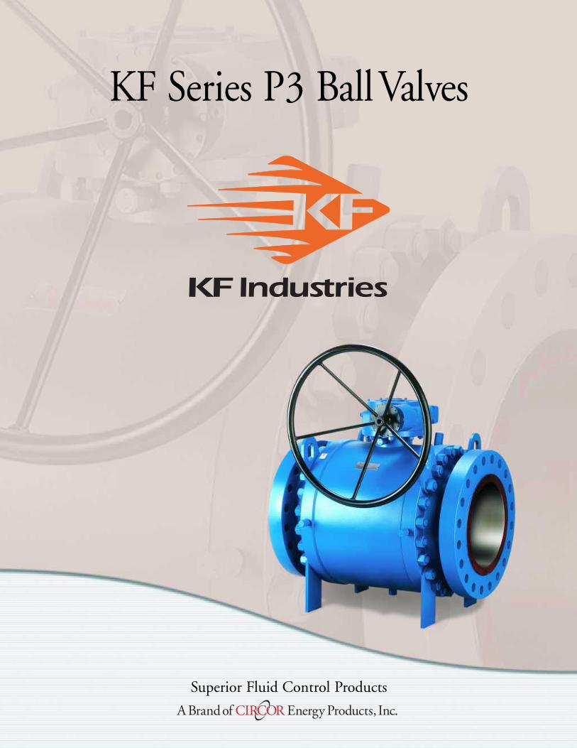
A large trunnion design ensures central positioningunder the highest working pressure. Independentfloating spring loaded seats provide a tight seal even atlow differential pressures. Service and maintenance issimplified with a bolted body design incorporating
KF Series P3 Trunnion Mounted Ball Valves
double O-rings or a combination of O-rings and gas-kets, suitable for buried or above ground installation.See page 6 for complete product offering.
NEW: Class 2500 now available. See page 6 for details.

3KF Series P3 Ball Valves
Anti-Blowout Stem DesignStem seal integrity isachieved by the use ofthree o-rings (or two o-rings and a graphitegasket). Upper o-ring(or graphite gasket)can be replaced withthe valve in line andunder pressure.
Emergency SealantInjection System The Sealant InjectionSystem located on thebonnet can be utilizedin case of emergencies,o-ring damage, or ifstem leakage occurs.
EmergencySeat SealSpecial sealants may beinjected thru fittings thatare located on theadapter flanges to restoresealing integrity if seatsealing surface is dam-aged. A second internalcheck valve providesbackup to the fitting.
Double SealedEnvelopeConnectionsDouble o-rings or acombination of an o-ring and firesafe gasket on body/adapterconnections to ensurepositive sealing. Thismakes the P3 suitablefor above or belowground service.
Antistatic DeviceA spring between thetrunnion and the ball or between the stem and the gland plate permits electrical continuity between allvalve components.
HeavyDutyBearingsTrunnions are supportedby heavy duty Teflon®
coated Steel Bearings.Thrust load on the ball is supported by largetrunnions mounted within captured trunnionblocks, resulting in lowoperating torque and seat wear.
6"-12" Cl. 900 & 150014"-24" Cl.150, 300 & 600
Stem Ball
Gland Flange
Ball
Heavy Duty Bearings*
*2"-12" Cl. 150, 300 & 600
Heavy Duty Bearings*
Heavy Duty Bearings*
Trunnion
Design Features

4 KF Series P3 Ball Valves
Technical Seating Features
Double Piston Seat Design
Upstream Seat: Line Pressure acting onthe seat area (A1) does not equalizeagainst the line pressure acting on theseat area (A2). The difference in thearea (D1) times the line pressure cre-ates a “piston effect” force whichpushes the seat against the ball surfaceresulting in a tight effective seal.
Downstream Seat: When the body cavity pressure isgreater than the downstream pressure, the body cavitypressure acts on the seal area (A4). The net pressure dif-ference, acting over area (D2), pushes the downstreamseat tightly against the ball creating a positive seal.
CLOSEDBALL
Downstream Seat
PD-Line Pressure
D2=A4-A3
PB=Body Cavity Pressure
A3
D 2D1
A1 A4
A2
Upstream Seat
PL-Line Pressure
D1=A1-A2
FLOWLINE
Self Relieving Seat Design
Upstream Seat: The difference in thearea (D1) times the line pressure cre-ates a “piston effect” which forces theseat against the ball surface. Also thesprings behind the seat adds the forceto the seat which keeps the seat incontact with the ball surface by pro-viding the tight seal.
Downstream Seat: When the body cav-ity pressure exceeds the spring pressure, automatic pres-sure relief will occur by relieving the body cavity pressurepast the downstream seat. This eliminates the need forthe body relief valve.
Double Block and Bleed
The double block and bleed conditionis available in all seat design configura-tions. When the ball is in the closedposition the body cavity pressure maybe drained down to ‘zero’ by openingthe bleed valve and draining the fluidby removing the drain plug. Each seatworks independently assuring tightshut off seal against ball on theupstream and downstream side.
THE ULTIMATE BENEFIT OF USING THE “DOUBLE PISTON SEAT”DESIGN: In case of upstream seat leakage, the down-stream seat maintains a pressure assisted tight shut off bysealing against the ball surface.
CLOSEDBALL
PB=Body Cavity PressureUpstream Seat
PL-Line Pressure
D1= A1-A 2
FLOWLINE
Downstream Seat
PD-Line Pressure
A2A2
D 1
A1
D 1
A1
CLOSEDBALL
Cavity PressureIs Drained Or Vented
To Atmosphere
FLOWLINE
PB=Body Cavity Pressure Is ZEROUpstream Seat
PL-Line PressureDownstream Seat
PD-Line Pressure

API-American Petroleum Institute
6D Specification for pipeline valves.
RP6F Recommended practice for fire testing of valves.
6FA Specification for fire testing of valves.
598 Valve inspection and test.
605 Large diameter carbon steel flanges.
607 Fire test for soft seated quarter-turn valves.
ASME/ANSI-American National Standard Institute
B 16.5 Steel pipe flanges and flanged fittings.
B 16.10 Face-to-face and end-to-end dimensions
of ferrous valves.
B 16.25 Butt welding ends.
B 16.34 Steel valves- Flanged and butt welding ends.
B 16.47 Steel Flanges.
B 31.3 Chemical plant and petroleum refinery piping
B 31.4 Liquid petroleum transportation piping systems.
B 31.8 Gas transmission and distribution piping systems.
B 46.1 Surface texture.
ASTM-American Society for Testing Materials
Consult factory for details.
ISO-International Organization for Standardization
ISO 9001: Quality systems-Model for quality assurance
2000 in design/development, production,
installation and servicing.
ISO 5211 Topworks Mounting Dimensions
ISO 15156 For use in H2S containing environments
in oil and gas production.
British Standard
BS 1503 Specification for steel forgings for pressure
purposes.
BS 1504 Specification for steel castings for pressure
purposes.
BS 1560 Steel pipe flanges and flanged fittings.
BS 2080 Face-to-face, center-to-face, end-to-end, and
center-to-end dimensions of flanged and
butt welding end steel valves for the petro-
leum, petrochemical and allied industries.
BS 4504 Flanges and boltings for pipes, valves and
fittings.
BS 5146 Inspection and test of steel valves for the
petroleum, petrochemical and allied industries.
BS 5351 Steel ball valves for the petroleum,
petrochemical and allied industries.
BS 5750 Quality system.
BS 6755 Testing of valves.
MSS-Manufacturers Standardization Society
SP 6 Standard finishes for contact faces of pipe
flanges and connecting- end flanges of
valves and fittings.
SP 25 Standard marking system for valves,
fittings, flanges and unions.
SP 45 Bypass and drain connection standard.
NACE-National Association of Corrosion Engineers
MR0175 Sulfide stress cracking resistant metallic
materials for oilfield equipment.
5KF Series P3 Ball Valves
KF Series P3 Applicable Standards
The following list contains the most important applica-ble standards for ball valves. KF valves may be designed,
manufactured and tested in accordance with otherinternational standards on request.

ClassSize (in.)
16 FP 18 FP 20 RP 20 FP 22 FP 24 RP 24 FP 26 FP 28 FP 30 RP 30 FP 32 FP 34 FP 36 RP 36 FP150 V127 V129 V130 V131 V133 V134 V135 V137 V139 V140 V141 V143 V145 V146 V147
300 V227 V229 V230 V231 V233 V234 V235 V237 V239 V240 V241 V243 V245 V246 V247
600 V327 V329 V330 V331 V333 V334 V335 V337 V339 V340 V341 V343 V345 V346 V347
900 V427 V429 V430 V431 — V434 V435 V437 V439 V440 V441 V443 V445 V446 V447
1500 V527 V529 V530 V531 — — V535 — — — — — — — —
Note: Shaded items are not available at this time. (Consult factory for verification)
ClassSize (in.)
2 FP 3 RP 3 FP 4 RP 4 FP 6 RP 6 FP 8 RP 8 FP 10 RP 10 FP 12 RP 12 FP 14 RP 14 FP 16 RP
150 V111 V112 V113 V114 V115 V116 V117 V118 V119 V120 V121 V122 V123 V124 V125 V126300 V211 V212 V213 V214 V215 V216 V217 V218 V219 V220 V221 V222 V223 V224 V225 V226
600 V311 V312 V313 V314 V315 V316 V317 V318 V319 V320 V321 V322 V323 V324 V325 V326900 V411 V412 V413 V414 V415 V416 V417 V418 V419 V420 V421 V422 V423 V424 V425 V426
1500 V511 V512 V513 V514 V515 V516 V517 V518 V519 V520 V521 V522 V523 V524 V525 V526
NEW 2500 V611 V612 V613 V614 V615 V616 V617 V618 V619 V620 V621 V622 V623 — — —
VXXX - X XX X X X X X XX
AssemblyBaseNumber
End Connection & Seat Configuration
Weld End Wall Thickness
Body/Bolting Material
NACE Conformance
Trim
Seat Insert/FS
Seal Material
Actuation
Downstream RelievingSeat Configuration
1 • RF2 • RTJ3 • WE
99 • No Weld EndXX • See Weld Chart page 7.
NACE** III, Cl. III Bolting
A • A105/B7 (Black - Std.)* B • SS/B7 (Xylan) C • LF2/L7 (Black) D • SS/L7 (Xylan) E • LF2/B7 (Black)L • A105/B7 (Xylan)
2 • 316SS3 • 410SS or CA-15M6 • CS w/ 3 mil ENP (Std. on 2" & larger)*7 • LTCS (3 mil ENP)
A • Devlon® / FS (KF Std.)*B • Teflon® / FSC • PEEK™ / FS
2 • Viton® A4 • EPDM 5 • AFLAS®
4 • Locking Handle (Std. on 2" thru 4" bore)*6 • Locking Gear Operator (Std. on 6" bore and larger)*9 • Bare StemA • For Actuator
Process Codes(Last two digits used ONLY when Process Codes are required).
Double Piston Seat ConfigurationInsert Type
F • RFG • RTJH • WE
NACE** II, Cl. II Bolting
N • A105/B7M P • SS/B7M (Xylan) Q • SS/L7M (Xylan) R • A105/B7M CadS • LF2/L7M T • SS/660SS
A • James Walker Viton®
F • ELAST-O-LION 985G • HNBR (Std.)
Asterisk ( * ) in lieu of dash ( - ) in Assembly Part Number indicates customer requires source inspection.. (i.e. VXXX * XXXXXXXXXX)
Devlon® is a registered trademark of Devol Engineering, Ltd. PEEK™ is a trademark of Victrex Plc. Teflon® is a registered trademark of DuPont. Viton® is a registered trademark of DuPont Dow Elastomers.Aflas® is a registered trademark of Asahi Glass.**Nace indicates compliance to NACE MR0175
*STANDARD TRIM CONFIGURATION
4 • RF x WE5 • RTJ x WE
J • RF x WEK • RTJ x WE
Series P3 Assembly Base Numbers, 2" FP -36" FP
6 KF Series P3 Ball Valves
KF Series P3 • Part Number Codes
2" FP- 36" FP, Class 150, 300, 600, 900, 1500 & 2500
NEW: Class 2500 now available. Consult Factory for more information.

7KF Series P3 Ball Valves
Pipe Nominal Pipe Size (in.)/KF Schedule CodeDescription 2 Code 3 Code 4 Code 6 Code 8 Code 10 Code 12 Code
Outside Dia. (in.) 2.375 3.500 4.500 6.625 8.625 10.750 12.750
(STD) Standard — — — — .237 17 .280 22 .322 28 .365 32 .375 33
Schedule 40 .154 08 .216 14 .237 17 .280 22 .322 28 .365 32 .406 35
XS .218 15 .300 24 .337 30 .432 36 .500 39 .500 39 .500 39
Schedule 80 .218 15 .300 24 .337 30 .432 36 .500 39 .593 43 .687 48
Schedule 160 .343 31 .438 38 .531 40 .718 49 .906 55 1.125 62 1.312 68
XXS .436 37 .600 44 .674 47 .864 53 .875 54 1.000 58 1.000 58
Pipe Size (in.)/KF Schedule CodeDescription 14 Code 16 Code 18 Code 20 Code 22 Code 24 Code
Outside Dia. (in.) 14.000 16.000 18.000 20.000 22.000 24.000
(STD) Standard .375 33 .375 33 .375 33 .375 33 .375 33 .375 33
Schedule 40 .438 38 .500 39 .562 42 .593 43 — — .687 47
XS .500 39 .500 39 — — — — 0.500 39 — —
Schedule 80 .750 50 .843 52 .937 56 1.031 59 1.125 62 1.218 65
Schedule 160 1.406 70 1.593 75 1.781 78 1.968 82 — — 2.343 85
XXS — — — — — — — — — — — —
Consult factory for other wall thicknesses.
Pipe Wall Thickness Codes for Assembly Part NumberKF Series P3 Buttweld End Pipe Code
Pipe Outside Dia. (O.D.)Calculating Pipe Wall ThicknessTo find the “Pipe Wall Thickness” for buttweld valves, subtract the Inside Diameterfrom the “Pipe Outside Diameter” for the appropriate size, listed to the right. Thendivide the outcome by two (2).
EXAMPLE: For a 4" valve with a 3.826 Inside Diameter:
Once you have determined the “Pipe Wall Thickness”, find that number in the chartabove. The two-digit number to the left should then be used in the “Pipe WallThickness” digits of the valve Assembly Part Number. In this example that would be 30.
Outside Diametertaken from the chart
at right
Inside Diameter Given by Customer
4.500 – 3.8262
= .337
Size (in.) in. mm2 2.375 60.333 3.500 88.904 4.500 114.306 6.625 168.288 8.625 219.08
10 10.750 273.0512 12.750 323.8514 14.000 355.6016 16.000 406.4018 18.000 457.2020 20.000 508.0024 24.000 609.60

8 KF Series P3 Ball Valves
Parts List, KF P31
Part No. Description
1 Body
2 Adapter
3 Bonnet
4 Ball
5 Stem
6 Lower Trunnion
7 Seat Assembly
8 Top Cover
9 Seat Springs
10 Stem Bearing
11 Lower Trunnion Bearing
12 Adapter Primary Seal
13 Adapter Sub-Seal
14 Bonnet Primary Seal
15 Bonnet Sub-Seal
16 Lower Trunnion Primary Seal
17 Lower Trunnion Sub-Seal
18 Stem Seal
Part No. Description
19 Stem Sub-Seal
20 Seat Seal
21 Seat Seal Backup
22 Seat Sub-Seal
23 Stud, Body
24 Nut, Body
25 Cap Screw, Bonnet
26 Cap Screw, Top Cover
27 Cap Screw, Lower Trunnion
28 Thrust Bearing
29 Bleed/Drain Valve
30 Injection Fitting
31 Ball Check
32 Drain Plug
34 Key
36 Alignment Pin, Bonnet
42 Antistatic Pin
43 Antistatic Spring
24
302729
43
426
17
16
23
15
14
42
43
28
3
18
25
26
5
30
36
19
8
11
28
1
7
3130
31
29
1312
2220
21
47
189
224
21
10
36
20
1222
KF Series P31 • Component Parts • 2", 3"& 4", Class 600, 900 &1500

9KF Series P3 Ball Valves
Part No. Description
1 Body
2 Adapter
3 Bonnet
4 Ball
5 Stem
6 Lower Trunnion
7 Seat Assembly
8 Top Cover
9 Seat Springs
10 Stem Bearing
11 Lower Trunnion Bearing
12 Adapter Primary Seal
13 Adapter Sub-Seal
14 Bonnet Primary Seal
15 Bonnet Sub-Seal
16 Lower Trunnion Primary Seal
17 Lower Trunnion Sub-Seal
18 Stem Seal
Part No. Description
19 Stem Sub-Seal
20 Seat Seal
21 Seat Seal Backup
22 Seat Sub-Seal
23 Stud, Body
24 Nut, Body
25 Cap Screw, Bonnet
26 Cap Screw, Top Cover
27 Cap Screw, Lower Trunnion
28 Thrust Bearing
29 Bleed/Drain Valve
30 Injection Fitting
31 Ball Check
32 Drain Plug
34 Key
36 Alignment Pin, Bonnet
42 Antistatic Pin
43 Antistatic Spring
Parts List, KF P32
26
25
18
3
14
10
1523
47
2120
2212
139
2
24
8
19
36
5
41
40
36
2120
2212
139
152
31
30
7
1
28
31
30
11
6
29
17
16
42
43
27
24
30
3428
KF Series P32 • Component Parts • 6"-12", Class 600

Part No. Description
18 Stem Seal
19 Stem Sub-Seal
20 Seat Seal
21 Seat Seal Backup
22 Seat Sub-Seal
23 Stud, Body
24 Nut, Body
25 Cap Screw, Bonnet
26 Cap Screw, Top Cover
28 Thrust Bearing
29 Bleed/Drain Valve
30 Injection Fitting
31 Ball Check
32 Drain Plug
34 Key
36 Alignment Pin, Bonnet
46 Trunnion Block Pin
Part No. Description
1 Body
2 Adapter
3 Bonnet
4 Ball
5 Stem
6 Trunnion Block
7 Seat Assembly
8 Top Cover
9 Seat Springs
10 Stem Bearing
11 Lower Trunnion Bearing
12 Adapter Primary Seal
13 Adapter Sub-Seal
14 Bonnet Primary Seal
15 Bonnet Sub-Seal
16 Lower Trunnion Primary Seal
17 Lower Trunnion Sub-Seal
10 KF Series P3 Ball Valves
Parts List, KF P33
20
46
10
11
34
28
15
3
19
8
26
327
2022
1312
241
29 2324
23
31
30
92
5
18
30
25
36
14
11
46
10
466
46
622
31
47
1213
92
30
KF Series P33 • Component Parts • 6"-12", Class 900 & 1500
14" & Larger, All Classes
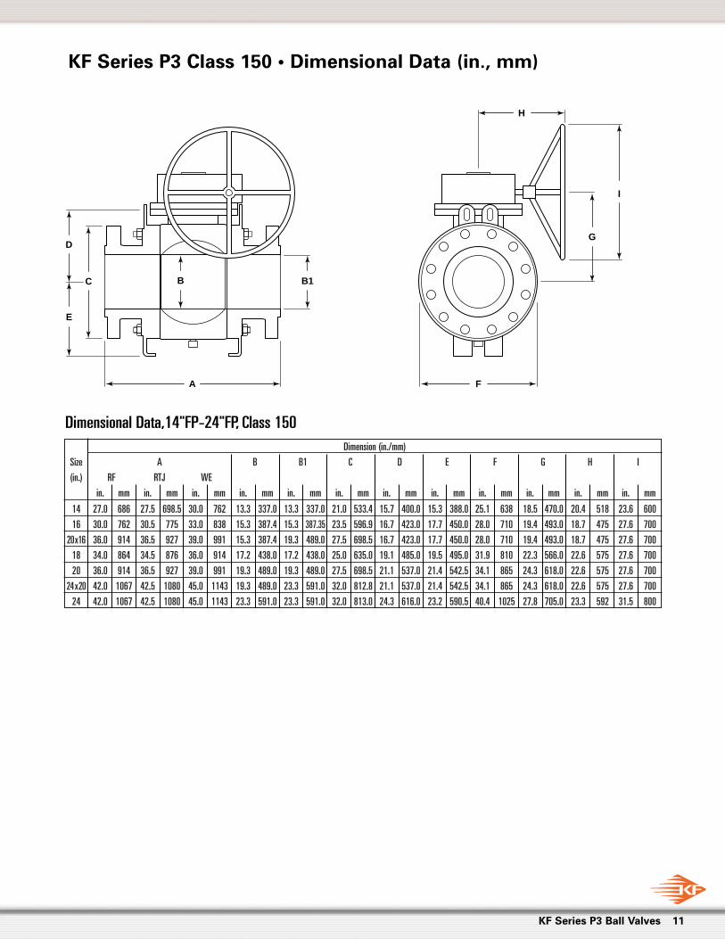
Dimension (in./mm)
Size A B B1 C D E F G H I
(in.) RF RTJ WE
in. mm in. mm in. mm in. mm in. mm in. mm in. mm in. mm in. mm in. mm in. mm in. mm
14 27.0 686 27.5 698.5 30.0 762 13.3 337.0 13.3 337.0 21.0 533.4 15.7 400.0 15.3 388.0 25.1 638 18.5 470.0 20.4 518 23.6 600
16 30.0 762 30.5 775 33.0 838 15.3 387.4 15.3 387.35 23.5 596.9 16.7 423.0 17.7 450.0 28.0 710 19.4 493.0 18.7 475 27.6 700
20x16 36.0 914 36.5 927 39.0 991 15.3 387.4 19.3 489.0 27.5 698.5 16.7 423.0 17.7 450.0 28.0 710 19.4 493.0 18.7 475 27.6 700
18 34.0 864 34.5 876 36.0 914 17.2 438.0 17.2 438.0 25.0 635.0 19.1 485.0 19.5 495.0 31.9 810 22.3 566.0 22.6 575 27.6 700
20 36.0 914 36.5 927 39.0 991 19.3 489.0 19.3 489.0 27.5 698.5 21.1 537.0 21.4 542.5 34.1 865 24.3 618.0 22.6 575 27.6 700
24x20 42.0 1067 42.5 1080 45.0 1143 19.3 489.0 23.3 591.0 32.0 812.8 21.1 537.0 21.4 542.5 34.1 865 24.3 618.0 22.6 575 27.6 700
24 42.0 1067 42.5 1080 45.0 1143 23.3 591.0 23.3 591.0 32.0 813.0 24.3 616.0 23.2 590.5 40.4 1025 27.8 705.0 23.3 592 31.5 800
Dimensional Data,14"FP-24"FP, Class 150
11KF Series P3 Ball Valves
C
E
D
B1B
I
G
A F
H
KF Series P3 Class 150 • Dimensional Data (in., mm)

Dimension (in./mm)
Size A B B1 C D E F G H I
(in.) RF RTJ WE
in. mm in. mm in. mm in. mm in. mm in. mm in. mm in. mm in. mm in. mm in. mm in. mm
14 30.0 762 30.6 778 30.0 762 13.3 337.0 13.3 337.0 23.0 584.0 15.7 400.0 15.3 388.0 25.1 638 18.5 470.0 20.4 518 23.6 600
16 33.0 838 33.6 854 33.0 838 15.3 387.4 15.3 387.4 25.5 648.0 16.7 423.0 16.7 425.0 28.0 710 19.4 493.0 22.6 575 27.6 700
20 x16 39.0 991 39.8 1010 39.0 991 15.3 387.4 19.3 489.0 30.5 775.0 16.7 423.0 16.7 425.0 28.0 710 19.4 493.0 22.6 575 27.6 700
18 36.0 914 36.6 930 36.0 914 17.2 438.0 17.2 438.0 28.0 711.0 19.2 488.0 19.6 498.0 32.3 820 22.4 569.0 22.6 575 27.6 700
20 39.0 991 39.8 1010 39.0 991 19.3 489.0 19.3 489.0 30.5 774.7 21.2 538.0 21.6 549.0 34.4 874 24.7 627.0 23.3 592 31.5 800
24x20 45.0 1143 45.9 1165 45.0 1143 19.3 489.0 23.3 591.0 36.0 914.0 21.2 538.0 21.6 549.0 34.4 874 24.7 627.0 23.3 592 31.5 800
24 45.0 1143 45.9 1165 45.0 1143 23.3 591.0 23.3 591.0 36.0 914.0 24.6 624.0 23.4 593.8 40.9 1040 29.3 744.0 27.3 693 35.4 900
12 KF Series P3 Ball Valves
KF Series P3 Class 300 • Dimensional Data (in., mm)
C
E
D
B1B
I
G
A F
H
Dimensional Data, 14"FP-24"FP, Class 300

Dimension (in./mm)
Size A B B1 C D E F G H I
(in.) RF RTJ WE
in. mm in. mm in. mm in. mm in. mm in. mm in. mm in. mm in. mm in. mm in. mm in. mm
2 11.5 292 11.6 295 11.5 292 2.0 51.0 2.0 51.0 6.5 165.0 6.1 155.0 4.2 106.3 6.5 165 22.8 580.0 — — — —
3x2 14.0 356 14.1 359 14.0 356 2.0 51.0 3.0 76.2 8.3 210.0 6.1 155.0 4.2 106.3 6.5 165 22.8 580.0 — — — —
3 14.0 356 14.1 359 14.0 356 3.0 76.2 3.0 76.2 8.3 210.0 6.7 170.0 5.4 136.3 9.0 229 27.6 700.0 — — — —
4 x3 17.0 432 17.1 435 17.0 432 3.0 76.2 4.0 101.6 10.7 273.0 6.7 170.0 5.4 136.3 9.0 229 27.6 700.0 — — — —
4 17.0 432 17.1 435 17.0 432 4.1 103.4 4.1 103.3 10.8 273.1 8.0 201.0 6.4 162.3 10.4 264 27.8 704.9 — — — —
6x4 22.0 559 22.1 562 22.0 559 4.1 103.4 6.0 152.4 14.0 356.0 8.0 201.0 6.4 162.3 10.4 264 27.8 704.9 — — — —
6 22.0 559 22.1 562 22.0 559 6.0 152.4 6.0 152.4 14.0 356.0 9.1 230.0 9.2 234.5 12.6 319 11.2 285.0 14.2 360 19.7 500
8x6 26.0 660 26.1 664 26.0 660 6.0 152.4 8.0 203.2 16.5 419.1 9.1 230.0 9.2 234.5 12.6 319 11.2 285.0 14.2 360 19.7 500
8 26.0 660 26.1 664 26.0 660 8.0 203.0 8.0 203.2 16.5 419.1 11.4 290.5 12.4 316.0 17.0 432 13.5 342.5 15.0 380 23.6 600
10x8 31.0 787 31.1 791 31.0 787 8.0 203.0 10.0 254.0 20.0 508.0 11.4 290.5 12.4 316.0 17.0 432 13.5 342.5 15.0 380 23.6 600
10 31.0 787 31.1 791 31.0 787 10.0 254.0 10.0 254.0 20.0 508.0 13.0 329.0 15.7 399.0 20.4 518 15.5 393.0 16.5 418 23.6 600
12x10 33.0 838 33.1 841 33.0 838 10.0 254.0 12.0 304.8 22.0 559.0 13.0 329.0 15.7 399.0 20.4 518 15.5 393.0 16.5 418 23.6 600
12 33.0 838 33.1 841 33.0 838 12.0 304.8 12.0 304.8 22.0 558.8 15.9 404.7 17.8 451.0 24.5 622 18.7 474.7 21.5 545 27.6 700
14x12 35.0 889 35.1 892 35.0 889 12.0 304.8 13.3 337.0 23.7 603.0 15.9 404.7 17.8 451.0 24.5 622 18.7 474.7 21.5 545 27.6 700
16x12 39.0 991 39.1 994 39.0 991 12.0 304.8 15.3 387.4 27.0 686.0 15.9 404.7 17.8 451.0 24.5 622 18.7 474.7 21.5 545 27.6 700
14 35.0 889 35.1 892 35.0 889 13.3 337.0 13.3 337.0 23.7 603.0 15.7 400.0 15.3 388.5 25.1 638 18.9 481.0 23.1 588 31.5 800
16 39.0 991 39.1 994 39.0 991 15.3 387.4 15.3 387.4 27.0 686.0 17.4 443.0 17.6 445.8 28.9 735 20.6 524.0 22.6 575 27.6 700
20x16 47.0 1194 47.2 1200 47.0 1194 15.3 387.4 19.3 489.0 32.1 815.0 17.4 443.0 17.6 445.8 28.9 735 20.6 524.0 22.6 575 27.6 700
18 43.0 1092 43.1 1095 43.0 1092 17.2 438.0 17.2 438.0 29.3 743.0 19.6 498.0 20.1 510.5 33.1 840 23.1 587.0 23.3 592 31.5 800
20 47.0 1194 47.2 1200 47.0 1194 19.3 489.0 19.3 489.0 32.0 812.8 22.2 565.0 21.3 542.0 36.2 920 27.0 685.0 27.3 693 35.4 900
24x20 55.0 1397 55.4 1407 55.0 1397 19.3 489.0 23.3 591.0 37.0 940.0 22.2 565.0 21.3 542.0 36.2 920 27.0 685.0 27.3 693 35.4 900
24 55.0 1397 55.4 1407 55.0 1397 23.3 591.0 23.3 591.0 37.0 940.0 24.6 624.5 23.5 596.0 41.1 1045 30.8 781.5 37.4 950 27.6 700
30Consult Factory
36
13KF Series P3 Ball Valves
KF Series P3 Class 600 • Dimensional Data (in., mm)
C
Lever Operated2"-6" RP
E
D
B1B
I
G
A
G
F
H
Dimensional Data, 2"FP-36"FP, Class 600

Dimension (in./mm)
Size A B B1 C D E F G H I
(in.) RF RTJ WE
in. mm in. mm in. mm in. mm in. mm in. mm in. mm in. mm in. mm in. mm in. mm in. mm
2 14.5 368 14.6 371 14.5 368 2.0 50.8 2.0 50.8 8.5 215.9 5.8 148.5 4.6 116.8 7.3 185 22.8 580 — — — —
3x2 15.0 381 15.1 384 15.0 381 2.0 50.8 3.0 76.2 9.5 241.3 5.8 148.5 4.6 116.8 7.3 185 22.8 580 — — — —
3 15.0 381 15.1 384 15.0 381 3.0 76.2 3.0 76.2 9.5 241.0 7.0 179.0 5.7 144.3 9.3 237 27.6 700 — — — —
4 x3 18.0 457 18.1 460 18.0 457 3.0 76.2 4.0 101.6 11.5 292.1 7.0 179.0 5.7 144.3 9.3 237 27.6 700 — — — —
4 18.0 457 18.1 460 18.0 457 4.1 103.3 4.1 103.3 11.5 292.0 8.5 216.2 6.9 176.3 11.3 288 33.7 856.2 — — — —
6x4 24.0 610 24.1 613 24.0 610 4.1 103.3 6.0 152.4 15.0 381.0 8.5 216.2 6.9 176.3 11.3 288 33.7 856.2 — — — —
6 24.0 610 24.1 613 24.0 610 6.0 152.4 6.0 152.4 15.0 381.0 10.0 255.0 10.0 255.0 14.2 360 12.1 307 14.8 377 23.6 600
8x6 29.0 737 29.1 740 29.0 737 6.0 152.4 8.0 203.2 18.5 470.0 10.0 255.0 10.0 255.0 14.2 360 12.1 307 14.8 377 23.6 600
8 29.0 737 29.1 740 29.0 737 8.0 203.2 8.0 203.2 18.5 469.9 11.7 296.0 12.6 320.0 17.3 440 14.2 360 21.5 545 27.6 700
10x8 33.0 838 33.1 841 33.0 838 8.0 203.2 10.0 254.0 21.5 546.0 11.7 296.0 12.6 320.0 17.3 440 14.2 360 21.5 545 27.6 700
10 33.0 838 33.1 841 33.0 838 10.0 254.0 10.0 254.0 21.5 546.0 13.5 342.0 16.0 406.0 20.9 532 16.2 412 20.4 518 23.6 600
12x10 38.0 965 38.1 968 38.0 965 10.0 254.0 12.0 304.8 24.0 610.0 13.5 342.0 16.0 406.0 20.9 532 16.2 412 20.4 518 23.6 600
12 38.0 965 38.1 968 38.0 965 12.0 304.8 12.0 304.8 24.0 609.6 16.4 416.0 18.2 462.5 25.4 645 19.6 497 23.1 588 31.5 800
14x12 40.5 1029 40.9 1038 40.5 1029 12.0 304.8 12.8 324.0 25.3 642.0 16.4 416.0 18.2 462.5 25.4 645 19.6 497 23.1 588 31.5 800
16x12 44.5 1130 44.9 1140 44.5 1130 12.0 304.8 14.8 374.7 27.8 705.0 16.4 416.0 18.2 462.5 25.4 645 19.6 497 23.1 588 31.5 800
14 40.5 1029 40.9 1038 40.5 1029 12.8 324.0 12.8 324.0 25.3 641.4 15.6 395.0 16.5 420.0 24.8 630 18.7 476 23.1 588 31.5 800
16 44.5 1130 44.9 1140 44.5 1130 14.8 374.7 14.8 374.65 27.8 705.5 18.3 465.5 19.4 491.9 29.3 745 21.8 554.5 23.3 592 31.5 800
18
20 Consult Factory
24
14 KF Series P3 Ball Valves
KF Series P3 Class 900 • Dimensional Data (in., mm)
C
Lever Operated2"-6" RP
E
D
B1B
I
G
A
G
F
H
Dimensional Data, 2"FP-24"FP, Class 900

Dimension (in./mm)
Size A B B1 C D E F G H I
(in.) RF RTJ WE
in. mm in. mm in. mm in. mm in. mm in. mm in. mm in. mm in. mm in. mm in. mm in. mm
2 14.3 368 14.6 371 14.5 368 2.0 50.8 2.0 50.8 8.5 215.9 6.8 172.0 5.3 134.3 8.4 214 22.0 558.8 — — — —
3x2 18.3 470 18.6 473 18.5 470 2.0 50.8 3.0 76.2 10.5 266.7 6.8 172.0 5.3 134.3 8.4 214 22.0 558.8 — — — —
3 18.3 470 18.6 473 18.5 470 3.0 76.2 3.0 76.2 10.5 266.7 8.6 219.0 7.1 180.3 11.8 300 27.6 700 — — — —
4 x3 21.2 546 21.6 549 21.5 546 3.0 76.2 4.1 103.3 12.2 311.0 8.6 219.0 7.1 180.3 11.8 300 27.6 700 — — — —
4 21.2 546 21.6 549 21.5 546 4.1 103.3 4.1 103.3 12.2 311.0 9.2 234.5 7.8 197.3 13.0 330 39.4 1000 — — — —
6x4 27.4 705 28.0 711 27.8 705 4.1 103.3 5.7 146.0 15.5 394.0 9.2 234.5 7.8 197.3 13.0 330 39.4 1000 — — — —
6 27.4 705 28.0 711 27.8 705 5.7 146 5.7 146.0 15.5 394.0 11.3 288.0 11.2 285.0 16.5 420 13.9 352 20.4 518 23.6 600
8x6 32.8 832 33.1 841 32.8 832 5.7 146 7.6 194.0 19.0 483.0 11.3 288.0 11.2 285.0 16.5 420 13.9 352 20.4 518 23.6 600
8 32.8 832 33.1 841 32.8 832 7.6 194 7.6 193.7 19.0 482.6 13.7 347.0 14.5 369.0 21.2 538 16.4 417 22.6 575 27.6 700
10x8 39.0 991 39.4 1000 39.0 991 7.6 194 9.5 241.0 23.0 585.0 13.7 347.0 14.5 369.0 21.2 538 16.4 417 22.6 575 27.6 700
10 39.0 991 39.4 1000 39.0 991 9.5 241 9.5 241.3 23.0 585.0 15.6 397.0 17.9 455.0 24.8 630 18.8 478 23.1 588 31.5 800
12x10 44.5 1130 45.1 1146 44.5 1130 9.5 241 11.4 289.0 26.5 673.0 15.6 397.0 17.9 455.0 24.8 630 18.8 478 23.1 588 31.5 800
12 44.5 1130 45.1 1146 44.5 1130 11.4 289 11.4 289.0 26.5 673.0 19.1 486.0 20.9 530.0 30.7 780 22.3 567 23.1 588 31.5 800
16 Consult factory
15KF Series P3 Ball Valves
C
Lever Operated2"-6" RP
E
D
B1B
I
G
A
G
F
H
KF Series P3 Class 1500 • Dimensional Data (in., mm)
Dimensional Data, 2"FP-16"FP, Class 1500

16 KF Series P3 Ball Valves
ValveANSI
H I L M N Max Stem Break Torq. Express. (1)Size
ClassA B C D E F G Stud Sz. Hole J K No. Of C. Line Bore W SheerTorq. Torq. For P<=2160
(in.) UNC Dia. Holes Bore Depth ft.-lbs. in.-lbs. PSI in.-lbs. (2)(3)
2 600 0.871 — 1.319 3.760 0.709 5.906 4.921 1/2 -13 0.531 — — 4 0.787 0.512 *0.558 134 13140.409*P+
2 900 0.871 — 1.345 3.858 0.709 5.906 4.921 1/2 -13 0.531 — — 4 0.787 0.512 *0.558 135 16162 1500 1.103 — 1.988 4.094 1.063 5.906 4.921 1/2 -13 0.531 — — 4 0.787 0.551 *0.746 306 2224
708.20
3 600 1.378 — 2.010 4.429 0.787 6.240 5.433 1/2 -13 0.531 — — 4 — — *0.994 405 41511.758*P+
3 900 1.378 — 2.000 4.941 0.945 6.713 5.433 1/2 -13 0.531 — — 4 0.807 0.500 *0.994 630 54523 1500 1.493 — 1.973 4.921 1.181 6.693 5.512 5/8-11 0.657 — — 4 1.024 0.650 *0.993 726 8062
1548.75
4 600 1.497 — 1.687 5.020 1.220 6.890 5.512 5/8-11 0.657 3.939 0.118 4 0.984 0.630 *0.996 725 60432.319*P+
4 900 1.497 — 1.687 5.020 1.220 6.890 5.512 5/8-11 0.657 3.939 0.118 4 0.984 0.630 *0.996 728 77594 1500 1.774 — 2.402 5.925 1.220 8.268 6.496 3/4-10 0.787 5.120 0.118 4 1.181 0.787 *1.247 1337 11,203
2610.75
6 600 1.931 — 2.179 4.921 1.299 6.909 5.512 5/8-11 0.657 3.939 0.118 4 1.000 0.669 *1.247 1624 14,5807.446*P+
6 900 1.992 — 1.991 4.921 1.378 8.287 6.496 3/4-10 0.787 5.120 0.118 4 1.181 0.787 *1.247 1695 20,0906 1500 2.493 — 2.795 6.299 1.181 11.811 10.000 5/8-11 0.669 7.880 0.118 8 — — *1.747 3722 31,147
3559.47
8 600 2.870 3.191 3.588 6.297 1.732 8.287 6.496 3/4-10 0.787 5.120 0.157 4 1.165 0.787 0.750 7460 22,62811.535*P+
8 900 2.870 3.191 3.780 6.496 1.575 11.811 10.000 5/8-11 0.669 7.877 0.157 8 — — 0.750 7460 31,1648 1500 2.870 3.191 3.299 6.496 1.575 11.811 10.000 5/8-11 0.669 7.877 0.118 8 — — 0.750 7460 48,293
5556.03
10 600 3.240 3.613 3.581 6.900 0.986 11.319 10.000 5/8-11 0.657 7.877 0.118 8 — — 0.875 10,631 29,04214.402*P+
10 900 3.240 3.617 3.972 7.096 1.260 11.811 10.000 5/8-11 0.657 7.877 0.118 8 — — 0.875 10,631 39,69910 1500 3.240 3.617 3.775 7.490 1.457 11.811 10.000 5/8-11 0.669 7.877 0.118 8 — — 0.875 10,631 61,086
7726.94
12 600 3.994 4.426 4.244 8.500 1.319 12.000 10.000 5/8-11 0.657 7.877 0.118 8 — — 1.000 20,315 34,63916.6*P+
12 900 3.994 4.426 4.210 9.051 1.813 13.780 11.732 3/4-10 0.787 9.057 0.199 8 — — 1.000 20,315 46,92312 1500 3.990 4.426 4.210 9.445 1.813 13.780 11.732 3/4-10 0.787 9.057 0.199 8 — — 1.000 20,315 71,574
10071.30
14 150 3.240 3.613 3.603 8.071 1.299 11.811 10.000 5/8-11 0.657 7.875 0.118 8 — — 0.875 7444 25,00014 300 3.240 3.613 3.603 8.071 1.299 11.811 10.000 5/8-11 0.657 7.875 0.118 8 — — 0.875 7444 37,886 28.32*P+14 600 3.240 3.613 3.603 8.071 1.299 13.780 11.732 3/4-10 0.787 9.057 0.118 8 — — 0.875 10,631 58,843 16929.1714 900 3.240 3.613 3.287 7.874 1.457 13.780 11.732 3/4-10 0.827 9.057 0.118 8 — — 0.875 10,631 79,80016 150 3.240 3.613 3.838 8.228 1.299 11.811 10.000 5/8-11 0.657 7.875 0.118 8 — — 0.875 10,631 33,60216 300 3.240 3.613 3.838 8.228 1.299 11.811 10.000 5/8-11 0.657 7.875 0.118 8 — — 0.875 10,631 50,655
37.48*P+16 600 4.333 4.749 4.114 8.898 1.299 13.228 11.732 3/4-10 0.787 9.057 0.118 8 — — 1.000 26,103 78,39016 900 4.333 4.749 4.568 8.543 1.000 13.780 11.732 3/4-10 0.787 9.057 0.118 8 — — 1.000 26,103 106,125
22919.73
16 1500 Consult Factory18 150 4.333 4.749 3.996 9.055 1.299 13.228 11.732 3/4-10 0.787 9.057 0.118 8 — — 1.000 26,103 45,663
62.74*P+18 300 4.333 4.749 3.996 9.055 1.299 13.228 11.732 3/4-10 0.787 9.057 0.118 8 — — 1.000 26,103 74,21018 600 4.333 4.749 3.996 9.055 1.299 13.780 11.732 3/4-10 0.787 9.057 0.118 8 — — 1.000 26,103 120,637
27781.92
18 900 4.742 5.284 3.267 11.807 1.000 18.701 15.984 11/2-8 1.575 11.819 0.315 8 — — 1.250 60,984 167,06520 150 4.333 4.749 4.528 9.248 1.000 13.386 11.732 3/4-10 0.787 9.057 0.118 8 — — 1.000 26,103 57,608 91.86*P+20 300 4.323 4.749 4.449 9.248 1.417 13.780 11.732 3/4-10 0.787 9.057 0.118 8 — — 1.000 26,103 99,405 31428.1220 600 4.333 4.749 4.382 9.839 1.000 13.780 11.732 3/4-10 0.787 9.057 0.118 8 — — 1.000 26,103 167,38120 900 4.742 5.284 5.118 11.807 1.000 18.701 15.984 11/2-8 1.575 11.819 0.315 8 — — 1.250 60,984 235,35724 150 4.333 4.749 4.429 9.248 1.417 13.780 11.732 3/4-10 0.787 9.057 0.118 8 — — 1.000 26,103 110,228
141.23*P+24 300 4.333 4.749 4.429 9.248 1.417 13.780 11.732 3/4-10 0.787 9.057 0.118 8 — — 1.000 26,103 174,48724 600 4.725 5.257 4.331 11.020 2.362 18.701 15.984 11/2-8 1.575 11.819 0.394 8 — — 1.250 33,100 278,997
69976.95
24 900 5.741 6.391 6.259 12.386 1.181 18.701 15.984 11/2-8 1.575 11.817 0.118 8 — — 1.500 108,306 383,50830 600
36 600Consult Factory
C L O S E D
O P E N
TopworksDetail
Dowel Pins:Not Provided ByActuator Supplier
H • Stud SizeI • Hole Dia.L • No. of Holes
B
Stem Detail
W
Sq. Key • 8"- 24"
A
W
Flatted Stem • 2"- 6"
A Center FlowLine
D
CE
JGF
K
M
N
KF Series P3 Topworks (in.) & Stem Torque Data (in.-lbs.)
Pressure ratings are according to API 6D/ASME 16.34Class 150 P = 285 Class 900 P = 2220Class 300 P = 740 Class 1500 P = 3705Class 600 P = 1480
Note: (1) Torque at maximum differential pressure are tabulated(2) Torques expressions are suggested for other differential pressure(3) Differential pressure “P” in torque expressions is in PSI
* Stem with Double 'D' Flat Style

ValveANSI
H I L M N Max Stem Break Torq. Express. (1)Size
ClassA B C D E F G Stud Sz. Hole J K No. Of C. Line Bore W SheerTorq. Torq. For P<=10.21
(in.) UNC Dia. Holes Bore Depth Nm Nm MPa-Nm (2)(3)
2 600 22.1 — 33.5 95.5 18.0 150.0 125 1/2-13 13.5 — — 4 20.0 13.0 *14.17 181.7 148.456.702*P+
2 900 22.1 — 34.2 98.0 18.0 150.0 125 1/2-13 13.5 — — 4 20.0 13.0 *14.17 183.0 182.702 1500 28.0 — 50.5 104.0 27.0 150.0 125 1/2-13 13.5 — — 4 20.0 14.0 *18.95 414.9 251.12
80.022
3 600 35.0 — 51.1 112.5 20.0 158.5 138 1/2-13 13.5 — — 4 — — *25.25 549.1 469.1328.808*P+
3 900 35.0 — 50.8 125.5 24.0 170.5 138 1/2-13 13.5 — — 4 20.5 12.7 *25.25 854.2 616.343 1500 37.9 — 50.1 125.0 30.0 170.0 140 5/8-11 16.7 — — 4 26.0 16.5 *25.22 984.3 910.47
175
4 600 38.0 — 42.9 127.5 31.0 175.0 140 5/8-11 16.7 100.1 3.0 4 25.0 16.0 *25.30 983.0 682.9938.001*P+
4 900 38.0 — 42.9 127.5 31.0 175.0 140 5/8-11 16.7 100.1 3.0 4 25.0 16.0 *25.30 987.0 877.184 1500 45.1 — 61.0 150.5 31.0 210.0 165 3/4-10 20.0 130.0 3.0 4 30.0 20.0 *31.67 1812.7 1265.17
295
6 600 49.0 — 55.3 125.0 33.0 175.5 140 5/8-11 16.7 100.1 3.0 4 25.4 17.0 *31.67 2201.8 1648.00122.018*P+
6 900 50.6 — 50.6 125.0 35.0 210.5 165 3/4-10 20.0 130.0 3.0 4 30.0 20.0 *31.67 2298.1 2271.526 1500 63.3 — 71.0 160.0 30.0 300.0 254 5/8-11 17.0 200.2 3.0 8 — — *44.37 5046.4 3517.32
402.2
8 600 72.9 81.1 91.1 159.9 44.0 210.5 165 3/4-10 20.0 130.0 4.0 4 29.6 20.0 19.05 10,114.4 2557.74189.024*P+
8 900 72.9 81.1 96.0 165.0 40.0 300.0 254 5/8-11 17.0 200.1 4.0 8 — — 19.05 10,114.4 3523.658 1500 72.9 81.1 83.8 165.0 40.0 300.0 254 5/8-11 17.0 200.1 3.0 8 — — 19.05 10,114.4 5453.58
627.8
10 600 82.3 91.8 91.0 175.3 25.0 287.5 254 5/8-11 16.7 200.1 3.0 8 — — 22.23 14,413.7 3282.72236.006*P+
10 900 82.3 91.9 100.9 180.2 32.0 300.0 254 5/8-11 16.7 200.1 3.0 8 — — 22.23 14,413.7 4488.7110 1500 82.3 91.9 95.9 190.2 37.0 300.0 254 5/8-11 17.0 200.1 3.0 8 — — 22.23 14,413.7 6898.33
873.101
12 600 101.4 112.4 107.8 215.9 33.5 304.8 254 5/8-11 16.7 200.1 3.0 8 — — 25.40 27,543.4 3915.37272.024*P+
12 900 101.4 112.4 106.9 229.9 46.1 350.0 298 3/4-10 20.0 230.0 5.0 8 — — 25.40 27,543.4 5305.4112 1500 101.3 112.4 106.9 239.9 46.1 350.0 298 3/4-10 20.0 230.0 5.0 8 — — 25.40 27,543.4 8082.77
1138
14 150 82.3 91.8 91.5 205.0 33.0 300.0 254 5/8-11 16.7 200.0 3.0 8 — — 22.23 10,092.7 2822.5014 300 82.3 91.8 91.5 205.0 33.0 300.0 254 5/8-11 16.7 200.0 3.0 8 — — 22.23 10,092.7 4284.35 464.080*P+14 600 82.3 91.8 91.5 205.0 33.0 350.0 298 3/4-10 20.0 230.0 3.0 8 — — 22.23 14,413.7 6651.16 1912.90114 900 82.3 91.8 83.5 200.0 37.0 350.0 298 3/4-10 21.0 230.0 3.0 8 — — 22.23 14,413.7 9022.6116 150 82.3 91.8 97.5 209.0 33.0 300.0 254 5/8-11 16.7 200.0 3.0 8 — — 22.23 14,413.7 3793.6016 300 82.3 91.8 97.5 209.0 33.0 300.0 254 5/8-11 16.7 200.0 3.0 8 — — 22.23 14,413.7 5728.29
614.185*P+16 600 110.1 120.6 104.5 226.0 33.0 336.0 298 3/4-10 20.0 230.0 3.0 8 — — 25.40 35,390.9 8860.6316 900 110.1 120.6 116.0 217.0 25.4 350.0 298 3/4-10 20.0 230.0 3.0 8 — — 25.40 35,390.9 11,999.11
2589.8
16 1500 Consult Factory18 150 110.1 120.6 101.5 230.0 33.0 336.0 298 3/4-10 20.0 230.0 3.0 8 — — 25.40 35,390.9 5154.32
1028.12*P+18 300 110.1 120.6 101.5 230.0 33.0 336.0 298 3/4-10 20.0 230.0 3.0 8 — — 25.40 35,390.9 8392.8918 600 110.1 120.6 101.5 230.0 33.0 350.0 298 3/4-10 20.0 230.0 3.0 8 — — 25.40 35,390.9 13,636.31
3139.2
18 900 120.4 134.2 83.0 299.9 25.4 475.0 406 11/2-8 40.0 300.2 8.0 8 — — 31.75 82,683.2 18,890.0020 150 110.1 120.6 115.0 234.9 25.4 340.0 298 3/4-10 20.0 230.0 3.0 8 — — 25.40 35,390.9 6501.61 1505.31*P+20 300 109.8 120.6 113.0 234.9 36.0 350.0 298 3/4-10 20.0 230.0 3.0 8 — — 25.40 35,390.9 11,243.33 3551.220 600 110.1 120.6 111.3 249.9 25.4 350.0 298 3/4-10 20.0 230.0 3.0 8 — — 25.40 35,390.9 18,920.4220 900 120.4 134.2 130.0 299.9 25.4 475.0 406 11/2-8 40.0 300.2 8.0 8 — — 31.75 82,683.2 26,612.5524 150 110.1 120.6 112.5 234.9 36.0 350.0 298 3/4-10 20.0 230.0 3.0 8 — — 25.40 35,390.9 12,443.10
2314.336*P+24 300 110.1 120.6 112.5 234.9 36.0 350.0 298 3/4-10 20.0 230.0 3.0 8 — — 25.40 35,390.9 19,733.2624 600 120.0 133.5 110.0 279.9 60.0 475.0 406 11/2-8 40.0 300.2 10.0 8 — — 31.75 44,877.6 31,536.37
7907
24 900 145.8 162.3 159.0 314.6 30.0 475.0 406 11/2-8 40.0 300.2 3.0 8 — — 38.10 146,843.2 43,362.6330 60036 600
Consult Factory
17KF Series P3 Ball Valves
KF Series P3 Topworks (mm) & Stem Torque Data (Nm)
Pressure ratings are according to API 6D/ASME 16.34Class 150 P = 1.96 Class 900 P = 15.32Class 300 P = 5.11 Class 1500 P = 25.53Class 600 P = 10.21
Note: (1) Torque at maximum differential pressure are tabulated(2) Torques expressions are suggested for other differential pressure (3) Differential pressure “P” in torque expressions is in MPa
* Stem with Double 'D' Flat Style
C L O S E D
O P E N
TopworksDetail
Dowel Pins:Not Provided ByActuator Supplier
H • Stud SizeI • Hole Dia.L • No. of Holes
B
Stem Detail
W
Sq. Key • 8"- 24"
A
W
Flatted Stem • 2"- 6"
A Center FlowLine
D
CE
JGF
K
M
N

Size (in.)Cv Value
285 psi 740 psi 1480 psi 2220 psi 3705 psi
2 — — 350 320 330
3 x 2 — — 190 185 187
3 — — 1000 910 830
4 x 3 — — 560 505 510
4 — — 1850 1760 1660
6 x 4 — — 800 730 742
6 — — 4400 4300 4167
8 x 6 — — 2150 2010 2033
8 — — 8450 8400 8013
10 x 8 — — 4500 4160 4051
10 — — 14,250 14,160 13,309
12 x 10 — — 8000 7300 7117
12 — — 22,790 21,230 17,073
14 x 12 — — 13,990 — —
16 x 12 — — — — —
14 32,600 30,900 28,600 26,600 24,276
16 x 14 14,780 14,750 14,720 14,690 14,247
16 44,700 42,600 39,250 36,600 33,215
20 x 16 14,870 14,860 14,850 14,830 14,795
18 57,825 56,225 57,410 48,665 43,402
20 74,775 71,800 65,463 62,239 55,931
24 x 20 26,768 26,755 25,698 26,659 —
22 91,789 88,537 81,305 — —
24 113,284 109,414 98,963 93,993 83,926
Note: Consult factory for sizes not shown.
18 KF Series P3 Ball Valves
Flow Coefficient (Cv)
KF Series P3 Engineering Data
Method of Calculating FlowThe Flow Coefficient “Cv” of a valve is the flow rate of water(gallons/minute) through a fully opened valve, with a pressuredrop of 1 psi across the valve. To find the flow of liquidthrough valve from the Cv, use the following formulas:
Gas FlowQg = flow rate of gas (CFH at STP)P2 = outlet pressure (psia)
g = Specific gravity of gas (for air, g=1.000)
Liquid FlowQL= flow rate of liquid (gal./min.)∆P = differential pressure across the valve (psi)G = specific gravity of liquid (for water, G=1)
Body & Trim Materials
Pressure Rating (psig)Material ANSI Cl.150 ANSI Cl. 300 ANSI Cl. 600 ANSI Cl. 900 ANSI Cl.1500
A105, LF2 285 740 1480 2220 3705
F316 275 720 1440 2160 3600
Part Material
Body/Adapter A105, LF2, F316SS
Ball/Stem F316SS or CS+3 mil ENP
Seat Devlon®, Teflon®, PEEK™
Pressure Temperature Chart (Carbon Steel )
0
6500
6000
5000
4000
3000
2000
1000
100
Diffe
rentia
l Pres
sure-
PSI
200 300 400 500 600
HNBRPEEK ™
Devlon ® V
Class 600
Class 1500
Class 900
Class 150
Temperature-˚F
Viton ®, Viton ® GF, JW Viton ®
Aflas ®, EPDM**
Nylon/Buna N & LT Buna N, EPDM*
Teflon ®***Class 300
Class 2500
Low Temperature LimitsBody Material ˚F ˚C
A105 -20 -29
LF2 -50 -46
F316 -50 -46
Seat Material ˚F ˚C
Devlon V -50 -46
PEEK™ -50 -46
Teflon® -50 -46
Seal Material ˚F ˚C
Viton® -20 -29
HNBR -40 -40
* Chemical Service** Water & Steam service only***Teflon® not offered for Class 1500.
QL=Cv
P
G
Qg=61Cv
P2 Pg
For non-critical flow
{ P }P2<1.0

ValveANSI
Weight (lbs.) Weight (kg)
Size Port Valve With GOP With Valve With GOP With(in.)
ClassOnly Handle Wt. GOP Only Handle Wt. GOP
2 FP 600 81 86 38 119 37 39 18 55
2 FP 900 114 118 54 168 52 54 25 77
2 FP 1500 169 173 54 223 77 79 25 101
2 FP 2500 Consult Factory Consult Factory
3 RP 600 96 101 38 134 44 46 18 62
3 FP 600 160 168 54 214 73 76 25 98
3 RP 900 147 152 54 201 67 69 25 92
3 FP 900 216 223 54 270 98 101 25 123
3 RP 1500 210 214 54 264 95 97 25 120
3 FP 1500 386 390 45 431 175 179 21 196
3 RP/ FP 2500 Consult Factory Consult Factory
4 RP 600 216 223 54 270 98 101 25 123
4 FP 600 286 295 45 331 130 134 21 151
4 RP 900 288 296 54 342 131 134 25 156
4 FP 900 385 395 45 430 175 179 21 196
4 RP 1500 485 494 45 530 220 224 21 241
4 FP 1500 617 — 81 698 280 — 37 317
4 RP/ FP 2500 Consult Factory Consult Factory
6 RP 600 368 377 45 413 167 171 21 188
6 FP 600 498 — 84 582 226 — 38 264
6 RP 900 529 538 45 574 240 244 21 261
6 FP 900 762 — 92 854 346 — 42 388
6 RP 1500 816 — 81 897 370 — 37 407
6 FP 1500 1157 — 115 1272 525 — 53 577
6 RP/ FP 2500 Consult Factory Consult Factory
8 RP 600 604 — 84 688 274 — 38 312
8 FP 600 992 — 90 1082 450 — 41 491
8 RP 900 912 — 92 1004 414 — 42 456
8 FP 900 1344 — 112 1456 610 — 51 661
8 RP 1500 1356 — 115 1471 615 — 53 668
8 FP 1500 2149 — 196 2345 975 — 89 1064
8 RP/ FP 2500 Consult Factory Consult Factory
10 RP 600 1256 — 90 1346 570 — 41 611
10 FP 600 1653 — 115 1768 750 — 53 803
10 RP 900 1499 — 112 1611 680 — 51 731
10 FP 900 2010 — 198 2208 912 — 90 1002
10 RP 1500 2628 — 196 2824 1192 — 89 1281
10 FP 1500 3440 — 300 3740 1560 — 136 136
10 RP/ FP 2500 Consult Factory Consult Factory
12 RP 600 1834 — 115 1949 832 — 53 885
12 FP 600 2535 — 288 2823 1150 — 131 1281
12 RP 900 2226 — 198 2424 1010 — 90 1100
12 FP 900 2865 — 299 3164 1300 — 136 1436
12 RP 1500 4156 — 300 4456 1885 — 136 2021
12 FP 1500 4012 — 300 4312 1820 — 136 1956
12 RP/ FP 2500 Consult Factory Consult Factory
Note: Consult factory for sizes not shown.
ValveANSI
Weight (lbs.) Weight (kg)
Size Port Valve With GOP With Valve With GOP With(in.)
ClassOnly Handle Wt. GOP Only Handle Wt. GOP
14 FP 150 1781 — 198 1979 808 — 90 898
14 FP 300 2380 — 198 2578 1080 — 90 1170
14 RP 600 2491 — 288 2779 1130 — 131 1261
14 FP 600 3020 — 288 3308 1370 — 131 1501
14 FP 900 3339 — 198 3537 1515 — 90 1605
16 RP 150 1610 — 198 1808 730 — 90 820
16 FP 150 2799 — 198 2997 1270 — 90 1360
16 RP 300 2332 — 198 2530 1058 — 90 1148
16 FP 300 2870 — 194 3064 1302 — 88 1390
16 RP 600 3042 — 288 3330 1380 — 131 1511
16 FP 600 3791 — 293 4084 1720 — 133 1853
16 RP 900 3947 — 198 4145 1790 — 90 1880
16 FP 900 4596 — 476 5072 2085 — 216 2301
16 FP 1500 9393 — 842 10,235 4261 — 382 4643
18 FP 150 2921 — 293 3214 1325 — 133 1458
18 FP 300 4634 — 293 4927 2102 — 133 2235
18 FP 600 5742 — 476 6218 2605 — 216 2821
18 FP 900 6614 — 842 7456 3001 — 382 3383
20 RP 150 2667 — 198 2865 1210 — 90 1300
20 FP 150 4805 — 289 5094 2180 — 131 2311
20 RP 300 4909 — 293 5202 2227 — 133 2360
20 FP 300 5608 — 476 6084 2544 — 216 2760
20 RP 600 4785 — 646 5431 2170 — 293 2464
20 FP 600 6130 — 842 6972 2781 — 382 3163
20 RP 900 6549 — 842 7391 2971 — 382 3353
20 FP 900 9614 — 842 10,456 4361 — 382 4743
24 RP 150 5343 — 289 5632 2424 — 131 2555
24 FP 150 7680 — 476 8156 3484 — 216 3700
24 RP 300 6063 — 289 6352 2751 — 131 2882
24 FP 300 7960 — 842 8802 3611 — 382 3993
24 RP 600 7475 — 842 8317 3391 — 382 3773
24 FP 600 12,125 — 870 12,995 5500 — 395 5895
24 RP 900 12,303 — 842 13,145 5581 — 382 5963
24 FP 900 15,500 — 870 16,370 7031 — 395 7426
Note: All weights listed are estimated. Consult factory for sizes not shown.
19KF Series P3 Ball Valves
KF Series P3 Weights

Worldwide Sales Offices
KF Industries, a leading brand of CIRCOR Energy Products, Inc.
reaches into every corner of the globe serving the oil & gas and industrial marketplace.
Supplying an extensive range of product offerings
through a worldwide network of manufacturer representatives and distributors,
KF Industries is the right choice for all your flow control needs.
www.circorenergy.comKF-P3-Oct-07-HP • ©2007 CIRCOR Energy Products, Inc. • KF Industries is a Brand of CIRCOR Energy Products, Inc. • KF reserves the right to change designs, materials or specifications without notice or with-out obligation to furnish or install such changes on products previously or subsequently sold. • Viton® is a registered trademark of DuPont DowElastomers. • Teflon® is a registered trademark of DuPont. •PEEK™ is a trademark of Victrex Plc. • Devlon® is a registered trademark of Devol Engineering, Ltd. • Aflas® is a registered trademark of Asahi Glass.
Registered to the ISO 9001Quality System Standard,
accredited by U.K., Dutchand German qualifying
authorities.
Licensed for Manufacture in accordance with API 6A
& 6D and Firetestto API 6FA and 607
World Headquarters
KF Industries1500 S.E. 89th StreetOklahoma City, OK 73149 USAPhone: (405) 631-1533Fax: (405) 631-5034E-mail: [email protected]
Canada
KF Industries Canada9430-39th Avenue, EdmontonAlberta, Canada T6E 5T9Phone: (780) 463-8633Fax: (780) 461-1588E-mail: [email protected]
US Industrial
KF Contromatics Industrial Products1500 S.E. 89th StreetOklahoma City, OK 73149 USAPhone: (405) 631-1533Fax: (405) 631-5034E-mail: [email protected]