Embed Size (px)
Citation preview

Keysight TechnologiesWideband Digital Pre-Distortion with SystemVue and PXI Modular Instruments
Application Note
A transition is now underway in the
wireless communications industry, as
wireless service providers embrace
broadband communication standards
such as LTE-Advanced and IEEE
802.11ac. In order to achieve Gb/s
link-level throughput, these new
formats use wider bandwidths,
multiple-input multiple-output (MIMO)
space-time coding, and higher
order orthogonal frequency division
multiplexing (OFDM) modulation
formats. These requirements place
new demands on linearity, bandwidth
and power consumption in wireless
components. For example, LTE-
Advanced supports up to 100-MHz
bandwidth to reach 1Gb/s and 500
Mb/s data rates for the downlink and
uplink, respectively. IEEE 802.11ac
will support 80-MHz and 160-MHz
bandwidths to achieve throughputs of
at least 1 Gb/s for multi-station and
500 Mb/s maximum for a single link.
For the communications system
architect and the RF power amplifier
(PA) designer, these new formats
introduce a number of challenges.
Designers must determine the
performance gap between their
existing 3G designs and tomorrow’s
4G operating environments, and
whether these 3G designs will need
to be redesigned, or a new vendor
qualified. The hardware must also
meet or exceed absolute performance
metrics such as ACPR, EVM or
throughput (e.g., BLER, BER and PER),
while also meeting internal product
design goals.
Because smart phones and other
advanced wireless devices rely so
heavily on battery power, getting the
most efficiency out of a design is
critical. The RF PA plays a particularly
key role Choosing and designing the
right PA to meet design goals is a
significant challenge.
This application note outlines a
broadband modeling approach that
– quickly characterizes broadband RF
PA’s,
– assesses “how linearizable”
transceiver designs are, requiring
typical wireless engineering skill
sets and equipment; and
– helps estimate real-world 4G
performance, prior to committing to
intellectual property (IP), hardware
or implementation details.
Introduction

3
Figure 4. Multi-band integration of multiple RF PA’s, with further topologies possible to support
MIMO, beamforming and operational redundancy.
Power amplifiers are an essential
component in the overall performance
and throughput of wireless commu-
nications systems, and are inherently
nonlinear. That nonlinearity generates
spectral re-growth, which leads to
adjacent channel interference and
violations of the out-of-band emis-
sions standards mandated by regula-
tory bodies. It also causes in-band
distortion, which degrades the bit-
error-rate (BER) and data throughput
of the communications system.
Problem
Figure 1. Multi-band integration in the digital baseband, with a single analog upconver-
sion/transmit path.
Figure 2. Multi-band integration at the analog intermediate frequency (IF), with a common upconver-
sion and RF PA.
Figure 3. Multi-band integration after upconversion, at the RF carrier, with a common RF PA.
Figures 1-4 illustrate various transmit architecture options, according to where
the component carriers are combined, (e.g., at the digital baseband, in analog
waveforms before the RF mixer, after the mixer but before the PA, or after the
PA). While integrated RFIC SoCs, CMOS chipsets and base station architectures
each achieve their design goals in different ways, Figures 1-4 show that they
share a common challenge—the most common challenge for RF engineers—the
broadband PA design.

4
The next challenge is the trade-off
between the peak-to-average power
ratio (PAPR, or crest factor) and
power-added-efficiency (PAE). The
newer OFDM transmission formats.
The newer OFDM transmission
formats, such as 3GPP LTE, LTE-
Advanced, and 802.11ac, OFDM (e.g.,
such as 3GPP LTE and LTE-Advanced,
802.11ac), have high peak to average
power. Infrequent intervals of higher
peak power levels cause the PAs to
clip harder and degrade the spectral
mask compliance, EVM and BER for
the entire waveform. Operating the
PA at a lower power is one way to
reduce this nonlinearity.
Problem
However, this means that the PA
needs to be backed off well below its
long-term saturated power level. In
other words, for a large percentage
of the time, the PA is operating with
wasted capacity. This results in very
low efficiencies, typically less than
10% (more than 90% of the DC power
is lost and turns into heat). For a base
station, this reduces the service area
and increases both the capital and
operating expenses of the service
provider. For a mobile handset, this
also reduces the quality of service
(QoS) and battery life, leading to
customer dissatisfaction and lower
revenues. Linearization enables the
PA to be operated in its high PAE
region, near saturation and without
significant signal distortion, thus
reducing expenses.
Digital pre-distortion (DPD) is a
cost-effective way to accomplish
linearization. Today, turn-key,
commercial off-the-shelf (COTS)
chipsets and IP are available for
2G/3G formats to service this
need. However, in many cases,
these commercial DPD approaches
fall short of the 4G requirements.
Below is a summary of these and
other challenges facing today’s
physical layer communications
designers, with regard to DPD.

5
Commercial IP, Algorithms and Chipsets Challenges
– 4G Ready. May not yet support
the bandwidth, dynamic range and
performance needed for 4G.
– Closed IP. They do not allow
internal algorithmic access, to
enable proprietary studies and
customization of Crest Factor
Reduction (CFR), oversampling,
filtering, DPD coefficient extraction
and convergence, polynomial
depth, memory effects, and other
factors.
– Parts count. Add to the final
Bill-of-Materials (BOM) and parts
count. Would like to adds absorb
DPD into existing baseband DSP
without introducing external parts
or cost.
Additional Challenges Faced by Broadband DPD Designers
Modeling Hardware Challenges
– Bandwidth. Existing test
equipment platforms may not
physically support the required
hardware bandwidth of LTE-
Advanced with carrier aggregation,
or of 802.11ac, with the
oversampling required for DPD.
– Not extendable. Ad hoc solutions
with third-party demo boards may
be uncalibrated, not repeatable,
or not connected to an enterprise
hardware design flow. They may
also be difficult to automate.
– Evolving Standards. Need
re-configurable, standards-
compliant test vectors for emerging
standards, but the standards
are still evolving and may not be
available in existing equipment.
Or, personal algorithms for signal
generation and measurement are
not appropriate for working with
external partners.
Modeling Team Challenges
– Platform. A team of high-
performance Ph.D. modelers
spends time writing simple code
and “glue” in order to integrate
general-purpose toolsets. They
would like to use a better
stimulus/response modeling
platform to contribute higher
engineering value.
– Skill-level. High skill level required
for modeling and interpretation.
– Transportable IP. How to easily
demonstrate a solution outside the
lab environment to partners? How
to remain vendor neutral? How to
collaborate worldwide, with remote
access to shared test equipment,
device samples and use common
toolsets, interoperability, and
licenses?
– Current DPD methodologies
are not predictive. Would like
to virtualize the entire DPD/PA
modeling process by connecting
directly to RF EDA flows, for
concurrent RF and baseband
design.
6
Engineers migrating to 4G require a
solution that makes implementing
DPD fast and practical for 4G
communications systems—one that
can be used by engineers at all levels
of expertise and requires minimal
equipment. The tool set should be
accurate, avoid dependence on a
vendor-specific chipset or hardware
implementation for the initial
modeling, and able to absorb custom
DPD into the rest of the baseband
processing, preserving a lower
BoM. Moreover, it must support
connectivity with a range of other
tools for hardware verification.
One solution that meets this criterion
is the Keysight Technologies, Inc.
SystemVue platform with its add-on
DPD personality—the W1716 DPD
Builder. This utility features an easy,
wizard-based user interface that
helps users quickly model and correct
common sources of 4G memory
Solution
effects in both low and high-power
PA’s, as well as transceiver IC’s, and
even automatic gain control modules.
The W1716 DPD is aimed at early
R&D architecture and component
studies by wireless system architects
using common, off-the-shelf test
equipment already in a test lab.
Whereas proprietary DPD solutions
force a number of premature
implementation decisions simply
to perform a 4G feasibility study,
by using the W1716 DPD, wireless
architects can assess in minutes how
“linearizable” a component will be,
while still retaining ultimate hardware
flexibility and full 4G measurement
confidence. Keysight enables this
thanks to several key advantages: the
power and ease of the Keysight DPD
algorithms; the open, vendor-neutral
and technology-neutral approach
taken to the DPD and PA hardware;
the high performance and flexibility
of the Keysight instruments; and
the realistic, standards-compliant
waveforms (such as LTE and LTE-
Advanced with CFR) that are used for
the characterizations.
CFR supplements and improves the
effectiveness of DPD. In modern
communication systems, spectrally
efficient wideband RF signals have a
peak-to-average power ratio (PAPR)
as high as 13 dB. CFR preconditions
the signal to reduce signal peaks
without significant signal distortion.
By reducing PAPR, CFR allows the PA
to operate more efficiently at higher
power levels, without impacting
compliance with spectral mask and
EVM specifications. CFR acts on the
signal itself, whereas DPD corrects
for the PA nonlinearity, allowing the
signal to be run even higher.

7
Keysight PXI Modular Instruments for DPD
Unlike other approaches to DPD,
Keysight’s approach takes a
designer’s perspective by featuring
flexible, built-in modeling and
links to wideband, reconfigurable
instruments, such as Keysight’s
Modular PXI family (Figure 5).
Figure 5. In this setup, the AWG with SystemVue for LTE-A and 802.11ac provides the standard-based
signals required for component test, while the M9392A (running Keysight’s vector signal analysis
(VSA) software) captures the signal in order to measure the PA’s nonlinearities. Using SystemVue
with the M9330A andM9392A automates and controls the entire DPD design low.
The M9392A PXI vector signal analyzer provides analysis bandwidths of up
to 250 MHz in a frequency range from 2.25 GHz to 26.5 GHz, with full 89600
VSA software support. At the core of the M9392A vector signal analyzer is
the M9202A wideband IF digitizer, with a 2 GSa/s sample rate and 12-bit
resolution. The M9202A can be used with wideband downconverters and
signal conditioning modules to measure with better than -60 dBc SFDR in a
bandwidth up to 300 MHz. Using an M9362A-D01 wideband downconverter, DPD
measurements can be made in a frequency range from 50 MHz to 26.5 GHz.
The M9330A PXI AWG provides two synchronized outputs at 15-bit resolution.
With a 1.25 GSa/s sample rate, the M9330A can be used to generate IQ signals
to apply to an external IQ modulator such as the MXG or PSG signal generators
with up to 1 GHz bandwidth. It can also be used to generate an IF waveform
with up to 500 MHz bandwidth.
Solution
N5182B MXG(as external modulator)
Device Under Test
M9392A PXI VSAW1461 SystemVueW1716 DPD89600 VSA
M9330AAWG
Baseband I,Q

8
Figure 6 shows the architecture for
the digital pre-distorter of memory
polynomial. The first step is to
understand the physical mechanisms
behind the PA’s behavior and extract
DPD coefficients. The second step
involves constructing a pre-distorter
model to accurately capture both the
static nonlinearity and the memory
effects based on the first step. The
feedback path labeled “Predistorter
Training” (block A) has (n)/G as its
input, where G is the intended PA
small signal gain, and z(n) as its
output. The actual pre-distorter is an
exact copy of the feedback path (copy
of A); it has x(n) as its input and z(n)
as its output. Ideally, we would like
(n) = Gx(n), which renders z(n) = z(n)
and the error term e(n) = 0. Given
y(n) and z(n), this structure enables
us to find the parameters of block A
directly, which yields the pre-distorter.
The algorithm converges when the
error energy ║e(n)║2 is minimized.
Applying DPD to a Working Analog PA
Figure 6. The architecture for the digital pre-distorter.

9
Using the SystemVue W1716
DPD utility to characterize real PA
hardware is a straightforward process
that takes mere minutes, using the
setup and measurement steps shown
below (Figure 7). Note that the same
procedure can also be used for
simulation-based DPD extraction
(not discussed in this application
note).
Figure 7. Flowchart of DPD hardware
veriication.
Applying DPD to a Working Analog PA
Steps in the DPD modeling low:
1. The DPD stimulus waveform
(such as LTE-Advanced, 802.11ac
or customized waveform) is
calculated and downloaded into
the M9330A AWG via the W1716
DPD wizard. The baseband
AWG outputs I and Q analog
voltages to drive the baseband
inputs of the Keysight N5182B
MXG X-Series source. The MXG
then outputs a modulated RF
waveform as the stimulus to
the PA, with any flatness and
calibrations applied. Note that
for a large base station PA, an
external preamp may be needed
to drive the PA to approximately
its 1-dB compression point.
2. Both the raw input signal and
the PA’s amplified response are
captured using the M9392A
vector signal analyzer, and
brought back into SystemVue
via the connectivity provided by
the 89600 VSA software. Note
that the PA output signal may
need to be attenuated externally
before entering the M9392A to
avoid damaging or overloading
the analyzer, or degrading its
calibrated performance.
3. The W1716 DPD Builder
time-aligns and compares the
captured output waveform
versus the linearly-scaled input
waveform, to get an EVM history
that is characteristic of the DUT.
Based on this difference, the
DPD model is extracted, and
then verified in simulation. At
this point, you also have a “dirty
PA” model that can be used after
your measurement hardware is
disconnected.
4. To verify in hardware, the original
stimulus is now pre-distorted
and downloaded a second time
to the signal generator, to re-test
the PA. The linearized DPD+PA
response is captured using the
same physical connection as
Step 2.
5. The linearized DPD+PA response
is now analyzed and plotted.
10
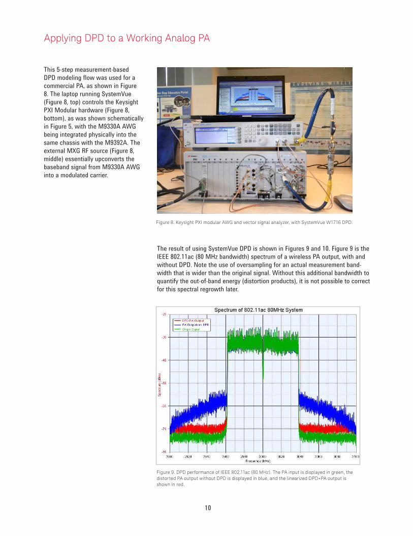
This 5-step measurement-based
DPD modeling flow was used for a
commercial PA, as shown in Figure
8. The laptop running SystemVue
(Figure 8, top) controls the Keysight
PXI Modular hardware (Figure 8,
bottom), as was shown schematically
in Figure 5, with the M9330A AWG
being integrated physically into the
same chassis with the M9392A. The
external MXG RF source (Figure 8,
middle) essentially upconverts the
baseband signal from M9330A AWG
into a modulated carrier.
Figure 8. Keysight PXI modular AWG and vector signal analyzer, with SystemVue W1716 DPD.
The result of using SystemVue DPD is shown in Figures 9 and 10. Figure 9 is the
IEEE 802.11ac (80 MHz bandwidth) spectrum of a wireless PA output, with and
without DPD. Note the use of oversampling for an actual measurement band-
width that is wider than the original signal. Without this additional bandwidth to
quantify the out-of-band energy (distortion products), it is not possible to correct
for this spectral regrowth later.
Figure 9. DPD performance of IEEE 802.11ac (80 MHz). The PA input is displayed in green, the
distorted PA output without DPD is displayed in blue, and the linearized DPD+PA output is
shown in red.
Applying DPD to a Working Analog PA

11
Figure 10 shows an LTE-Advanced
signal with 4x20 MHz carrier
aggregation (80 MHz total signal
bandwidth). The PA output spectrum
is shown with and without DPD.
Figure 10. DPD performance of LTE-A with 4x20 contiguous carrier aggregation. The PA input is dis-
played in green, the distorted PA output without DPD is displayed in blue, and the linearized DPD+PA
output is shown in red.
The Keysight SystemVue W1716 DPD provides the memory polynomial algorithm
as a C++ dataflow model and the memoryless polynomial algorithm as a .m
code (MATLAB format), which is visible to licensed users. Users can also take
advantage of the SystemVue platform as a modeling tool and integrate their own
digital pre-distortion algorithmic IP into the W1716 DPD wizard.
Applying DPD to a Working Analog PA

12
SystemVue DPD GUI
As of SystemVue 2011.10, the
W1716 DPD Builder graphical user
interface (GUI) supports two families
of Keysight instruments, as well as
simulation-based extraction. This
application note discusses integration
with the Keysight PXI Modular series
of instruments, as shown in the fol-
lowing section.
Support for EXG/MXG X-Series
sources and MXA/PXA signal analyz-
ers is discussed in Application Notes
http://cp.literature.keysight.com/
litweb/pdf/5990-6534EN.pdf and
http://www.keysight.com/litweb/
pdf/5990-7818EN.pdf. Simulation-
based DPD based on co-simulation
with Keysight Advanced Design
System, Keysight GoldenGate, and
X-parameter* devices is possible, but
beyond the scope of this document.
Figure 11. The graphical UI of step 1.
Step 2: Capture DUT Response
In this step, the PA input and output is captured from the M9392A using VSA
software.
Figure 12. The GUI of step 2.
Step 1: Create DPD Stimulus
The first step is to download a baseband waveform into the M9330A as DPD
stimulus. The M9330A is an AWG and needs MXG as an external modulator.
The values of FCarrier and RFPower in the GUI should be set manually in the
MXG.

13
Figure 14 shows the GUI by using the MATLAB code of the memoryless
polynomial algorithm when “Use Custom Model Extractor” and “Use Custom
Pre-Distorter” are enabled.
Step 3: Capture DUT Response
The next step, the most critical, is to extract the DPD coefficients for the
memory polynomial and memoryless polynomial using the PA input and output
waveform. Figure 13 shows the GUI by using the default memory polynomial
algorithm.
Figure 13. The GUI of step 3.
Figure 14. The SystemVue DPD wizard (release 2011.10 and later) allows custom IP to
be inserted for both the model extraction, and the actual pre-distorter.
After clicking the “Customized Model Extractor” item, the MATLAB code of the
memoryless polynomial algorithm used to extract the coefficients of the pre-
distorter is opened in the MathLang block (Figure 12). Customers can insert their
own DPD algorithm’s MATLAB code into this MathLang block to replace the
Keysight memoryless polynomial algorithm.
SystemVue DPD GUI

14
Figure 15. Custom code for the model extractor can be inserted here. A simple memoryless
polynomial nonlinearity is shown above, in MATLAB .m format.
To extract the coefficients for the digital pre-distorter, the digital pre-distorter
structure should be changed to correspond to the change algorithm. After click-
ing the “Customized Pre-Distorter” item, the MATLAB code of the memoryless
polynomial pre-distorter is shown in the MathLang block (Figure 16). Customers
should insert their MATLAB code to match their own digital pre-distortion
algorithm.
Figure 16. MATLAB pre-distorter code, native within the SystemVue environment. Step-by-step
debugging is provided within SystemVue, as well as optional direct invocation of the user’s full
MATLAB coniguration.
SystemVue DPD GUI

15
Figure 18. The GUI of step 5
Step 4: DPD Response
This fourth step is to generate a pre-distorted waveform using the memory poly-
nomial coefficients extracted in step 3. The value of RFPower
for the pre-distorted
waveform in GUI should be set to MXG manually.
Step 5: Verify DPD Response
The fifth step is to verify DPD performances by comparing the spectrums of PA
output with DPD and without DPD.
Figure 17. The GUI of step 4.
SystemVue DPD GUI
16
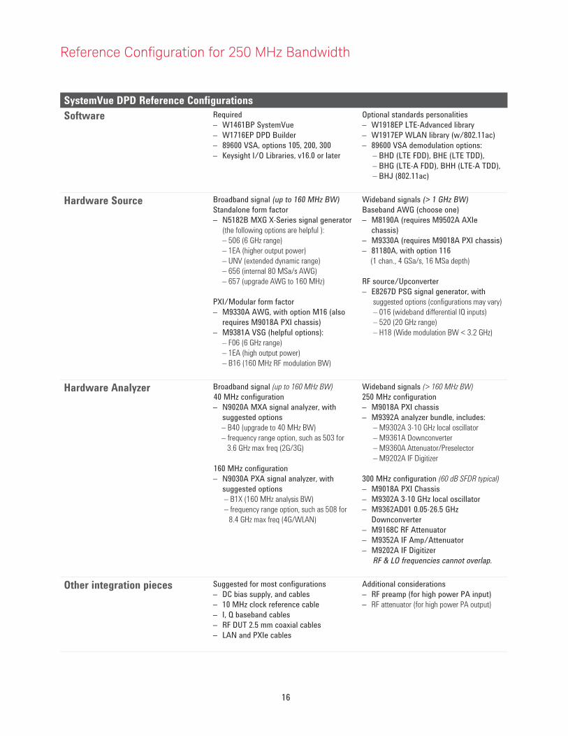
Reference Coniguration for 250 MHz Bandwidth
SystemVue DPD Reference Configurations
Software Required
– W1461BP SystemVue
– W1716EP DPD Builder
– 89600 VSA, options 105, 200, 300
– Keysight I/O Libraries, v16.0 or later
Optional standards personalities
– W1918EP LTE-Advanced library
– W1917EP WLAN library (w/802.11ac)
– 89600 VSA demodulation options:
– BHD (LTE FDD), BHE (LTE TDD),
– BHG (LTE-A FDD), BHH (LTE-A TDD),
– BHJ (802.11ac)
Hardware Source Broadband signal (up to 160 MHz BW)
Standalone form factor
– N5182B MXG X-Series signal generator
(the following options are helpful ):– 506 (6 GHz range)– 1EA (higher output power)– UNV (extended dynamic range)– 656 (internal 80 MSa/s AWG)– 657 (upgrade AWG to 160 MHz)
PXI/Modular form factor
– M9330A AWG, with option M16 (also
requires M9018A PXI chassis)
– M9381A VSG (helpful options):
– F06 (6 GHz range)– 1EA (high output power)– B16 (160 MHz RF modulation BW)
Wideband signals (> 1 GHz BW)
Baseband AWG (choose one)
– M8190A (requires M9502A AXIe
chassis)
– M9330A (requires M9018A PXI chassis)
– 81180A, with option 116
(1 chan., 4 GSa/s, 16 MSa depth)
RF source/Upconverter
– E8267D PSG signal generator, with
suggested options (configurations may vary)– 016 (wideband differential IQ inputs)– 520 (20 GHz range)– H18 (Wide modulation BW < 3.2 GHz)
Hardware Analyzer Broadband signal (up to 160 MHz BW)
40 MHz configuration
– N9020A MXA signal analyzer, with
suggested options
– B40 (upgrade to 40 MHz BW)– frequency range option, such as 503 for 3.6 GHz max freq (2G/3G)
160 MHz configuration
– N9030A PXA signal analyzer, with
suggested options
– B1X (160 MHz analysis BW)– frequency range option, such as 508 for
8.4 GHz max freq (4G/WLAN)
Wideband signals (> 160 MHz BW)
250 MHz configuration
– M9018A PXI chassis
– M9392A analyzer bundle, includes:
– M9302A 3-10 GHz local oscillator– M9361A Downconverter– M9360A Attenuator/Preselector– M9202A IF Digitizer
300 MHz configuration (60 dB SFDR typical)
– M9018A PXI Chassis
– M9302A 3-10 GHz local oscillator
– M9362AD01 0.05-26.5 GHz
Downconverter
– M9168C RF Attenuator
– M9352A IF Amp/Attenuator
– M9202A IF Digitizer
RF & LO frequencies cannot overlap.
Other integration pieces Suggested for most configurations
– DC bias supply, and cables
– 10 MHz clock reference cable
– I, Q baseband cables
– RF DUT 2.5 mm coaxial cables
– LAN and PXIe cables
Additional considerations
– RF preamp (for high power PA input)
– RF attenuator (for high power PA output)

17
As engineers migrate to advanced wireless communication systems such as
LTE-Advanced or 802.11ac, choosing and designing the right PA to meet design
goals at the lowest possible cost becomes more difficult, both for base stations
and mobile devices. Because DPD enables the PA to be operated with high
efficiency, near saturation and without significant signal distortion, it allows
engineers to address many base station/mobile device PA design challenges.
SystemVue with the W1716 DPD option provides the algorithmic sophistication
to work with 4G signals and formats, and interoperate with other trusted
personalities like Keysight’s 89600 VSA software. Keysight’s PXI Modular
instruments, such as the M9330A AWG and M9392A vector signal analyzer
provide a calibrated, broadband measurement platform that’s capable of DPD
modeling up to 250 MHz today, and can accommodate future expansion to meet
changing requirements.
A video demonstration of this configuration is available at
http://www.youtube.com/watch?v=bocF6P74T9E
Summary
For more information about SystemVue, please visit us on the web:
SW Product information
http://www.keysight.com/find/eesof-systemvue
HW Product information
http://www.keysight.com/find/modular
Request a 30-day Evaluation
http://www.keysight.com/find/eesof-systemvue-evaluation
Downloads
http://www.keysight.com/find/eesof-systemvue-latest-downloads
Helpful Videos
http://www.keysight.com/find/eesof-systemvue-videos
18 | Keysight | Wideband Digital Pre-Distortion with SystemVue and PXI Modular Instruments - Application Note
This information is subject to change without notice.© Keysight Technologies, 2011 - 2014Published in USA, August 1, 20145990-8883ENwww.keysight.com
For more information on Keysight
Technologies’ products, applications or
services, please contact your local Keysight
office. The complete list is available at:www.keysight.com/find/contactus
Americas
Canada (877) 894 4414Brazil 55 11 3351 7010Mexico 001 800 254 2440United States (800) 829 4444
Asia PaciicAustralia 1 800 629 485China 800 810 0189Hong Kong 800 938 693India 1 800 112 929Japan 0120 (421) 345Korea 080 769 0800Malaysia 1 800 888 848Singapore 1 800 375 8100Taiwan 0800 047 866Other AP Countries (65) 6375 8100
Europe & Middle East
Austria 0800 001122Belgium 0800 58580Finland 0800 523252France 0805 980333Germany 0800 6270999Ireland 1800 832700Israel 1 809 343051Italy 800 599100Luxembourg +32 800 58580Netherlands 0800 0233200Russia 8800 5009286Spain 0800 000154Sweden 0200 882255Switzerland 0800 805353
Opt. 1 (DE)Opt. 2 (FR)Opt. 3 (IT)
United Kingdom 0800 0260637
For other unlisted countries:www.keysight.com/find/contactus
(BP-07-10-14)