Embed Size (px)
Citation preview

Keysight TechnologiesMaking EMI Compliance Measurements
Application Note

02 | Keysight | Making EMI Compliance Measurements - Application Note
Table of Contents
Introduction to compliance measurements ........................................3
The compliance measurements process ............................................4
Compliance EMI receiver requirements ..............................................7
Requirements above 1 GHz .......................................................7
Conducted emissions measurements .................................................8
Conducted test setup ................................................................8
Coniguringthereceiver.............................................................8
Performing conducted emissions measurements ...................10
Radiated emissions measurements ................................................... 12
Open site requirements ............................................................ 12
Radiated emissions test setup ................................................. 13
Measuring radiated emissions ................................................. 14
Placement of EUT for maximum signals ........................................... 15
Ambient plus EUT measurements ........................................... 15
Appendix A - Line impedance stabilization networks ...................... 16
Appendix B - Antenna factors ........................................................... 18
Appendix C - Basic electrical relationships ......................................20
Appendix D - Detectors used in EMI measurements .......................21
Appendix E - EMC regulatory agencies ............................................24
Glossaryofacronymsanddeinitions ...............................................26

03 | Keysight | Making EMI Compliance Measurements - Application Note
Introduction to compliance measurements
Electrical or electronic equipment that uses the public power grid or has potential for
electromagnetic emissions must pass EMC (electromagnetic compatibility) require-
ments. These requirements fall into four broad types of testing: radiated and conducted
emissions testing, and radiated and conducted immunity testing.
Conducted emissions testing focuses on signals present on the AC mains that are gener-
ated by the equipment under test (EUT). The frequency range of these measurements is
typically 9 kHz to 30 MHz. However, MIL-STD measurement may have a wider frequency
range.
Radiated emissions testing searches for signals being emitted from the EUT through
space. The typical frequency range for these measurements is 30 MHz to 1 GHz
or 6 GHz, although FCC regulations require testing up to 40 GHz.
Figure 1 illustrates the difference between radiated emissions, radiated immunity,
conducted emissions, and conducted immunity. Radiated immunity is the ability of a
deviceorproducttowithstandradiatedelectromagneticields.Conductedimmunityisthe ability of a device or product to withstand electrical disturbances on power or data
lines. Immunity testing will not be covered in this document.
For an electromagnetic compatibility problem to occur (such as when an electric drill
interferes with TV reception), there must be a generator or source, a coupling path, and a
receptor. Until recently, most efforts to remove EMC problems have focused on reducing
the emissions of the source to an acceptable level—now both emissions and immunity
tests are performed.
Emission Immunity = Susceptibility
Figure 1. Four types of EMC measurements

04 | Keysight | Making EMI Compliance Measurements - Application Note
The compliance measurements process
Before compliance measurements can be performed on a product, some preliminary
questions must be answered:
1. Where will the product be sold (for example, the United States,Europe, or Japan)?
2. Whatistheclassiicationoftheproduct(forexample,informationtechnologyequip-
ment(ITE);industrial,scientiic,ormedical(ISM);automotiveandcommunications)?3. Where will the product be used (for example, home, commercial, light industry, or
heavy industry)?
With the answers to the above questions, you can determine which testing requirements
apply to your product by referring to Tables 1a and 1b below. For example, if you have
determined that your product is an ITE device that will be sold in the U.S., then you need
to test the product to FCC Part 15 regulations.
International regulations summary (emissions)
CISPR FCC EN Description
11 Part 18 EN 55011 Industrial, scientiic, and medical
13 Part 15 EN 55013 Broadcast receivers
14 EN 55014 Household appliances/tools
15 EN 55015 Fluorescent lights/luminaries
16-1-1 Measurement apparatus/methods
22 Part 15 EN 55022 Information technology equipment
25 EN 55025 Automotive
EN 50081-1,2 Generic emissions standards
Table 1a. Comparison of regulatory agency requirements
European Norms (EN)
Equipment type Emissions
Generic equipment EN 50081-1
Residential
Light industrial
Industrial EN 50081-2
Industrial, scientiic, medical products (ISM) EN 55011
Sound and broadcast receivers EN 55013
Household appliances EN 55014
Information technology equipment (ITE) EN 55022
Automotive EN55025
Table 1b. Major European requirements

05 | Keysight | Making EMI Compliance Measurements - Application Note
European Norms
EN55011(CISPR11)Industrial,scientiic,andmedicalproductsClass A: Used in establishments other than domestic areas.
Class B: Suitable for use in domestic establishments.
Group1:Laboratory,medical,andscientiicequipment.(Forexample,signalgenerators,measuring receivers, frequency counters, spectrum analyzers, switching mode power
supplies, weighing machines, and electronic microscopes.)
Group 2: Industrial induction heating equipment, dielectric heating equipment, industrial
microwave heating equipment, domestic microwave ovens, medical apparatus, spark
erosion equipment, and spot welders. (For example, metal melting, billet heating,
component heating, soldering and brazing, wood gluing, plastic welding, food process-
ing, food thawing, paper drying, and microwave therapy equipment.)
EN55014 (CISPR 14)
Electric motor-operated and thermal appliances for household and similar purposes,
electric tools, and electric apparatus. Depending on the power rating of the item being
tested, use one of the limits shown in Table 1c.
EN55014 Conducted household appliances QP
EN55014 Conducted household appliances AVE
EN55014 Conducted < 700 W motors QP
EN55014 Conducted < 700 W motors AVE
EN55014 Conducted > 700 W < 1000 W motors QP
EN55014 Conducted > 700 W < 1000 W motors AVE
EN55014 Conducted > 1000 W motors QP
EN55014 Conducted > 1000 W motors AVE
EN55014 Radiated household appliances QP
EN55014 Radiated household appliances AVE
EN55014 Radiated < 700 W motors QP
EN55014 Radiated < 700 W motors AVE
EN55014 Radiated > 700 W < 1000 W motors QP
EN55014 Radiated > 700 W < 1000 W motors AVE
EN55014 Radiated > 1000 W motors QP
EN55014 Radiated > 1000 W motors AVE
Note: The conducted range is 150 kHz to 30 MHz and the radiated range is 30 MHz to 300 MHz.
Table 1c. Tests based on power rating
EN55022 (CISPR 22) Information technology equipment
Equipment with the primary function of data entry, storage, displaying, retrieval, trans-
mission, processing, switching, or controlling. (For example, data processing equipment,
oficemachines,electronicbusinessequipment,andtelecommunicationsequipment.)
Class A ITE: Not intended for domestic use.
Class B ITE: Intended for domestic use.

06 | Keysight | Making EMI Compliance Measurements - Application Note
Federal Communications Commission
Equipment FCC
Broadcast receivers
Household appliances/tools Part 15
Fluorescent lights/luminaries
Information technology equipment (ITE)
Industrial, scientiic, medical products (ISM)
Conducted measurements: 450 kHz - 30 MHz Part 18
Radiated measurements: 30 MHz - 1000 MHz, 40 GHz
Table 1d. FCC regulations
Federal Communications Commission (FCC) FCC Part 15 Radio frequency devices—unintentional radiators
Equipment that unintentionally produces emissions that could interfere with other
devices. (For example, TV broadcast receivers, FM broadcast receivers, CB receivers,
scanning receivers, TV interface devices, cable system terminal devices, Class B
personal computers and peripherals, Class B digital devices, Class A digital devices and
peripherals, and external switching power supplies).
Class A digital devices are marketed for use in a commercial, industrial, or business
environment.
Class B digital devices are marketed for use in a residential environment.
For assistance, contact the agency for conformation of the applicable requirement—
see Appendix E for contact information.

07 | Keysight | Making EMI Compliance Measurements - Application Note
Compliance EMI receiver requirements
ThereareseveralrequirementsformakingcomplianceEMImeasurements.TheirstisanEMI receiver that meets CISPR 16-1-11, such as the N9038A MXE EMI receiver.
A CISPR 16-1-1 receiver must have the following functionality in the range
9 kHz - 18 GHz:
– A normal ±2 dB absolute amplitude accuracy
– CISPR-speciiedbandwidths(6dB)asindicatedinthechartbelow
Bandwidth Frequency range
200 Hz 9 kHz to 150 kHz
9 kHz 150 kHz to 30 MHz
120 kHz 150 kHz to 1000 MHz
1 MHz impulse 1 GHz to 18 GHz
Note:Thefrequencyresponseoftheiltersmustalsofallwithina“mask”deinedbyCISPR16-1-1.
– Peak,quasi-peak,EMIaverage,andRMSaveragedetectorswithspeciiedcharge,discharge time, and meter constants for the quasi-peak detector (see Appendix D for
a description of these detectors)
– Speciiedinputimpedancewithanominalvalueof50ohms;deviationsspeciiedasVSWR – Beabletopassproductimmunityina3V/mield – Be able to pass the CISPR pulse test
– Otherspeciicharmonicandintermodulationrequirements
TheCISPRpulsetestconsistsofbroadbandpulsesofadeinedspectralintensityofvarying repetition frequency presented to the EMI receiver. The quasi-peak detector
mustmeasurethesepulsesataspeciiedlevel,withinaspeciiedaccuracy.Inordertomeetthispulsetest,itisimplied,butnotspeciied,thatthereceivermusthave:
– Preselection—achievedbyinputiltersthattrackthereceivertuningtoreducebroadband noise overload at the front end mixer
– Sensitivityanddynamicrange—theEMIreceivermusthaveanoiseloorlowenoughto measure signals at low PRFs
A recommended feature for ensuring accurate measurements is overload detection.
To make an accurate measurement, the receiver must be in linear operating mode and
not be in saturation at the front-end mixer because of large narrowband signals or
broadband emissions. A useful overload detection scheme will alert the user to overload
conditions in all frequency ranges and in all modes of operation. An advanced overload
detectionandmeasurementschemewill“autorange,”orautomaticallyputinenoughattenuationpriortotheirstmixertomeasurethesignalinnon-overloadconditions.
Requirements above 1 GHz
Regulations require a 1 MHz bandwidth for measurements above 1 GHz. In addition, no
quasi-peak detector is required for measurements above 1 GHz. The CISPR pulse test is
not required above 1 GHz, but excellent sensitivity in the measuring system is important
toachievesuficientdynamicrangeinordertoperformthemeasurements.
AccordingtocurrentFCCregulations,themaximumtestfrequencyistheifthharmonicofthehighestclockfrequencyforan“unintentionalradiator”(forexample,computerswithout wireless connectivity) and the tenth harmonic for an intentional radiator (such as
a cellular phone or wireless LAN). 1. Comite International Special des Perturbations Radioelectriques

08 | Keysight | Making EMI Compliance Measurements - Application Note
Conducted emissions measurements
Emissions testing is divided into conducted emissions and radiated emissions testing.
Follow the steps outlined below to set up the test equipment,
accessories, and EUT.
Conducted test setup
ANSIC63.4describesaspeciictestsetupforconductedemissions.FCCPart15detailsthe limits for these tests. Refer to ANSI C63.4 for the latest conducted emissions setup—
CISPR 22 shows a similar conducted test setup for ENs.
ConiguringthereceiverInterconnect the EMI receiver, such as the Keysight Technologies, Inc. N9038A MXE,
LISN, and EUT. The function of a LISN is detailed in Appendix A.
1. Disconnect the input to the receiver.
2. Set up the correct frequency range by selecting CISPR Band B, which also selects
the correct bandwidth. Select the correct range in the scan table and switch on the
RF preselector.
3. Based on the type of equipment and the regulatory agency requirements, select the
appropriate limit line from a wide range of limits in the EMI receiver.
Note: This sequence of steps for making a compliant measurement with the EMI measurement receiver assumes that the measurement setup and measuring receiver are compliant with the applicable standard and a system alignment has been completed, if required.
Figure 2a. FCC Part 15 limits

09 | Keysight | Making EMI Compliance Measurements - Application Note
Coniguringthereceiver(continued)
4. Next, load correction factors for the LISN from the transducer list available
in the EMI receiver.
Figure 2b. Transducer correction factors with LISN
After loading the LISN correction factors and limit lines, and starting a scan, your display
should look similar to Figure 3.
Figure 3. Display with limit line and correction factors for conducted emission testing

10 | Keysight | Making EMI Compliance Measurements - Application Note
Performing conducted emissions measurements
At this point, the EMI receiver is set up with all of the correct parameters, including
bandwidth, frequency range, LISN compensation, and limit line. However, before starting
conducted measurements, consider the effect of the ambient environment on the results.
The power cable between the LISN and the EUT can act as an antenna, which can cause
false EUT responses on the display. To test that this phenomenon is not occurring, switch
offtheEUTandcheckthedisplaytoensurethatthenoiseloorisatleast6dBbelowthelimit line as shown in Figure 4.
Figure 4. Test for ambient signals
Switch on the power to the EUT and observe the display. If there are no signals above the
limit line, then your product passes the conducted emissions limit. Data and signals close
to the limit may need to be collected for your report. Remember that line and neutral
must be tested. If there are signals above the limit, closer analysis is needed.
Figure 5. Conducted emissions from DUT
11 | Keysight | Making EMI Compliance Measurements - Application Note
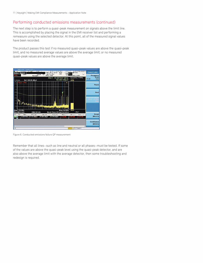
Performing conducted emissions measurements (continued)
The next step is to perform a quasi-peak measurement on signals above the limit line.
This is accomplished by placing the signal in the EMI receiver list and performing a
remeasure using the selected detector. At this point, all of the measured signal values
have been recorded.
The product passes this test if no measured quasi-peak values are above the quasi-peak
limit, and no measured average values are above the average limit; or no measured
quasi-peak values are above the average limit.
Figure 6. Conducted emissions failure QP measurement
Remember that all lines—such as line and neutral or all phases—must be tested. If some
of the values are above the quasi-peak level using the quasi-peak detector, and are
also above the average limit with the average detector, then some troubleshooting and
redesign is required.
12 | Keysight | Making EMI Compliance Measurements - Application Note
Radiated emissions measurements
Performing radiated emissions measurements is not as straightforward as performing
conducted EMI measurements. There is the added complexity of the open air ambient
environment, which can interfere with the emissions from the EUT. Fortunately, there are
methods to differentiate between signals in the ambient environment such as TV, FM,
and cellular radio.
Open site requirements
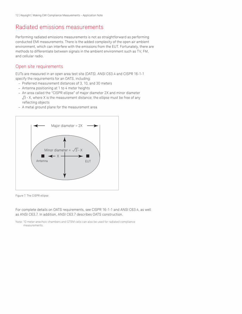
EUTs are measured in an open area test site (OATS). ANSI C63.4 and CISPR 16-1-1
specify the requirements for an OATS, including:
– Preferred measurement distances of 3, 10, and 30 meters
– Antenna positioning at 1 to 4 meter heights
– Anareacalledthe“CISPRellipse”ofmajordiameter2Xandminordiameter
√_3•X,whereXisthemeasurementdistance;theellipsemustbefreeofanyrelectingobjects
– A metal ground plane for the measurement area
Antenna EUT
Minordiameter=3•X
X
Majordiameter=2X
Figure 7. The CISPR ellipse
For complete details on OATS requirements, see CISPR 16-1-1 and ANSI C63.4, as well
as ANSI C63.7. In addition, ANSI C63.7 describes OATS construction.
Note: 10 meter anechoic chambers and GTEM cells can also be used for radiated compliance measurements.
13 | Keysight | Making EMI Compliance Measurements - Application Note
Radiated emissions test setupNote: The following sequence of steps for making a compliant measurement with the analyzer assumes that
the measurement setup is compliant with the applicable standard.
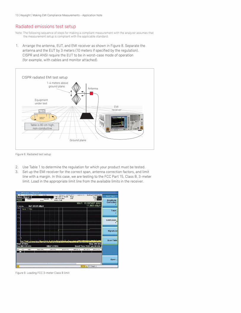
1. Arrange the antenna, EUT, and EMI receiver as shown in Figure 8. Separate the
antennaandtheEUTby3meters(10metersifspeciiedbytheregulation). CISPR and ANSI require the EUT to be in worst-case mode of operation
(for example, with cables and monitor attached).
CISPR radiated EMI test setup
Equipmentunder test
Antenna
EMIreceiver
Ground plane
1-4 meters aboveground plane
Table is 80 cm high,non-conductive
360°
Figure 8. Radiated test setup
2. Use Table 1 to determine the regulation for which your product must be tested.
3. Set up the EMI receiver for the correct span, antenna correction factors, and limit
line with a margin. In this case, we are testing to the FCC Part 15, Class B, 3-meter
limit. Load in the appropriate limit line from the available limits in the receiver.
Figure 9. Loading FCC 3-meter Class B limit

14 | Keysight | Making EMI Compliance Measurements - Application Note
Radiated emissions test setup (continued)
Figure 10. Load correction factors for the antenna
Load the appropriate antenna correction factors from the receiver. Since these are typi-
cal correction factors, you may need to edit them using the receiver's editing features.
So far, you have arranged the equipment with the EUT 3 meters from the antenna,
chosen the appropriate limit line, and corrected the display for antenna loss.
Measuring radiated emissions
The next step is to evaluate the radiated emissions from your product. With the EUT off,
sweep the frequency range of interest. This gives you a good idea of the ambient signal
levels. The ideal situation is to have all the ambient signals below the limit line. In many
cases, they are not, so it’s a good idea to measure and record them. The amplitude and
frequency of the ambient signals above the limit or margin can be stored in the receiver's
signal list for future comparison and removal.
Figure 11. Ambient signals placed in signal list

15 | Keysight | Making EMI Compliance Measurements - Application Note
Placement of EUT for maximum signals (manual measurement process)
Radiated emissions from electronic devices are not uniform. The strongest emissions
may be from the rear panel, front panel, or slots in the shielding. To ensure that you are
measuring the worst-case emissions from your device, follow the steps below:
1. With the EMI receiver adjusted to view the span of interest, move the EUT through a
360° rotation in 45° increments
2. At each 45° step, note the amplitude of the largest signal—save the screen to an
internalileforlaterreference
After all the screens have been captured, upload them into a graphics application so you
cancomparethescreencapturesside-by-side.Insomecases,youmayindthatthereare worst-case emissions for different frequencies at different positions. For example,
youmayindworst-casefor100MHzemissionsat90°,andat270°for200MHz.Inthisexample, the emissions tests must be performed at both positions. If you are not sure
whether the signal you are looking at is an ambient or EUT signal, switch off the EUT—an
ambient signal will not change. Worst-case emissions must be found for both horizontal
and vertical antenna polarizations.
Ambient plus EUT measurements
Orient the EUT to one of the worst-case positions. There may be more than one EUT
position with emissions above the limit line. A quasi-peak measurement must be
performed on each of these above-the-line emissions. If the quasi-peak measurement
still indicates a failure, then some troubleshooting and repair is required. The solution
could be as simple as poor cable grounding or unwanted slots in the shielding.
Ifthereareseveralsignalsabovethelimitthatarenotidentiiedasambientsignals,youshould zoom in on one or two at a time, measuring the quasi-peak value of each. Using
software to perform the above processes allows for more repeatable measurements and
documentation.
Figure 12. Ambient environment plus DUT emissions

16 | Keysight | Making EMI Compliance Measurements - Application Note
Appendix A
Line impedance stabilization networks
Purpose of a LISN
A line impedance stabilization network serves three purposes:
1. The LISN isolates the power mains from the EUT. The power supplied to the EUT
must be as clean as possible. Any noise on the line will be coupled to the EMI
receiver and interpreted as noise generated by the EUT.
2. The LISN isolates any noise generated by the EUT from being coupled to the power
mains. Excess noise on the power mains can cause interference with the proper
operation of other devices on the line.
3. The signals generated by the EUT are coupled to the EMI receiver using a high-pass
ilter,whichispartoftheLISN.Signalswhichareinthepassbandofthehigh-passiltershowa50Ωload,whichistheinputtotheEMIreceiver.
LISN operation
The diagram in Figure A-1 below shows the circuit for one side of the line relative to earth
ground.
Line impedance stabilization network (LISN)
605040302010
.01 .1 1 10 100
Impedance(ohms)
Frequency (MHz)
0.1 µF
1000W
From powersource
To EUT
To EMI receiver
(50 W)
50 µH
1 µF
Figure A-1. Typical LISN circuit diagram
The1µFcapacitor-incombinationwiththe50µHinductor,istheilterthatisolatesthe mains from the EUT. The 50 µH inductor isolates the noise generated by the EUT
from the mains. The 0.1 µF capacitor couples the noise generated by the EUT to the
EMIreceiver.Atfrequenciesabove150kHz,theEUTsignalsarepresentedwitha50Ωimpedance.
The chart in Figure A-1 represents the impedance of the EUT port versus frequency.

17 | Keysight | Making EMI Compliance Measurements - Application Note
Appendix A (continued)
Types of LISNs
Types of LISNs
V-LISN: -LISN:
T-LISN:
Unsymmetric emissions (line-to-ground) Symmetric emissions (line-to-line)Asymmetric emissions (mid point line-to-line)
V-LISN Vector diagram
V symmetric
Ground
H N
V unsymm
etric
1
V2 unsy
mm
etric
1/2 V symmetric 1/2 V symmetric
V unsymm
etric
1
V unsymmetric2V asymmetric
Figure A-2. Three different types of LISNs
The most common type of LISN is the V-LISN. It measures the asymmetric voltage
between line and ground. This is done for both the hot and the
neutrallines,orforathree-phasecircuitina“Y”coniguration,betweeneach line and ground. There are some other specialized types of LISNs.
A delta LISN measures the line-to-line or symmetric-emissions voltage.
The T-LISN, sometimes used for telecommunications equipment, measures
the asymmetrical voltage, which is the potential difference between the
midpoint potential between two lines and ground.

18 | Keysight | Making EMI Compliance Measurements - Application Note
Appendix B
Antenna factors
Field strength units
RadiatedEMIemissionsmeasurementsmeasuretheelectricield.TheieldstrengthiscalibratedindBμV/m.FieldstrengthindBμV/misderivedfromthefollowing:
Pt = total power radiated from an isotropic radiator
PD=thepowerdensityatadistancerfromtheisotropicradiator(farield)
PD = Pt/4πr2 R=120πΩ
PD = E2/R
E2/R = Pt/4πr2
E = (Pt x 30)1/2 /r (V/m)
Farield*isconsideredtobe>λs/2π
*Farieldistheminimumdistancefromaradiatorwheretheieldbecomesaplanarwave.
Antenna factors
Thedeinitionofantennafactorsistheratiooftheelectricieldinvoltspermeterpresentat the plane of the antenna, versus the voltage out of the antenna connector.
Note: Antenna factors are not the same as antenna gain.
Antenna factors
Linear units:
dB/m
Frequency, MHz
5
10
15
20
25
0 200 400 600 800 1000
Biconical@ 10m
Log periodic@ 1m
AF = Antenna factor (1/m) E = Electric field strength (V/m) V = Voltage output from antenna (V)
Log units: AF(dB/m) = E(dBµV/m) - V(dBµV) E(dBµV/m) = V(dBµV) + AF(dB/m)
AF =V out
30
Ein
Figure B-1. Typical antenna factor shapes

19 | Keysight | Making EMI Compliance Measurements - Application Note
Appendix B (continued)
Types of antennas used for commercial radiated measurements
Blah
Log periodic antenna
Biconical antenna
Broadband antenna
(30 - 300 MHz)
(30 - 1000 MHz) (200 - 1000 MHz)
Figure B-2. Antennas used in EMI emissions measurements
There are three types of antennas used for commercial radiated emissions
measurements.
Biconical antenna: 30 MHz to 300 MHz
Log periodic antenna: 200 MHz to 1 GHz
(the biconical and log periodic overlap frequency)
Broadband antenna: 30 MHz to 1 GHz
(larger format than the biconical or log periodic antennas)
20 | Keysight | Making EMI Compliance Measurements - Application Note
Appendix C
Basic electrical relationships
The decibel is used extensively in electromagnetic measurements. It is the log of the ratio
oftwoamplitudes.Theamplitudesareinpower,voltage,amps,electricieldunits,andmagneticieldunits.
decibel = dB = 10 log (P2/P1)
Dataissometimesexpressedinvoltsorieldstrengthunits.
In this case, replace P with V2/R.
If the impedances are equal, the equation becomes:
dB = 20 log(V2/V1)
A unit of measure used in EMI measurements is dBµV or dBµA. The relationship of dBµV
and dBm is as follows:
dBµV = 107 + PdBm
Thisistrueforanimpedanceof50Ω.
Wavelength (l) is determined using the following relationship:
λ = 3x10⁸ / f (Hz) or λ = 300/f (MHz)

21 | Keysight | Making EMI Compliance Measurements - Application Note
Appendix D
Detectors used in EMI measurements—peak, quasi-peak, and average
Peak detector
Initial EMI measurements are made using the peak detector.
This mode is much faster than quasi-peak, or average modes of detection. Signals are
normally displayed on spectrum analyzers or EMI receivers in peak mode. Since signals
measured in peak detection mode always have amplitude values equal to or higher than
quasi-peak or average detection modes, it is a very easy process to take a sweep and
compare the results to a limit line. If all signals fall below the limit, then the product
passes, and no further testing is needed.
Peak detector operation
The EMI receiver has an envelope or peak detector in the IF chain with a constant time
such that the voltage at the detector output follows the peak value of the IF signal at all
times. In other words, the detector can follow the fastest possible changes in the envelope
of the IF signal, but not the instantaneous value of the IF sine wave (see Figure D-1).
Output of the envelope detector follows the peaks of the IF signal
Figure D-1. Peak detector diagram
22 | Keysight | Making EMI Compliance Measurements - Application Note
Appendix D (continued)
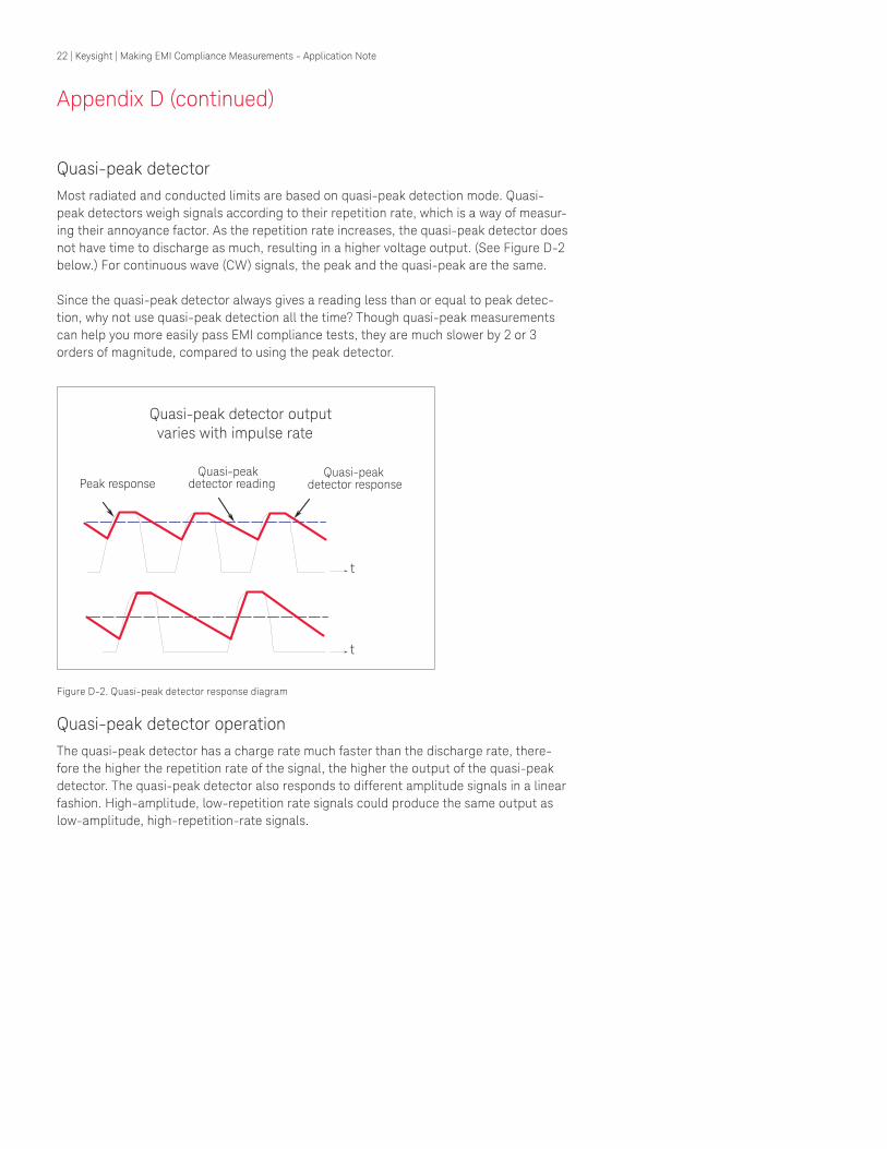
Quasi-peak detector
Most radiated and conducted limits are based on quasi-peak detection mode. Quasi-
peak detectors weigh signals according to their repetition rate, which is a way of measur-
ing their annoyance factor. As the repetition rate increases, the quasi-peak detector does
not have time to discharge as much, resulting in a higher voltage output. (See Figure D-2
below.) For continuous wave (CW) signals, the peak and the quasi-peak are the same.
Since the quasi-peak detector always gives a reading less than or equal to peak detec-
tion, why not use quasi-peak detection all the time? Though quasi-peak measurements
can help you more easily pass EMI compliance tests, they are much slower by 2 or 3
orders of magnitude, compared to using the peak detector.
Quasi-peak detector output varies with impulse rate
t
Peak responseQuasi-peak
detector readingQuasi-peak
detector response
t
Figure D-2. Quasi-peak detector response diagram
Quasi-peak detector operation
The quasi-peak detector has a charge rate much faster than the discharge rate, there-
fore the higher the repetition rate of the signal, the higher the output of the quasi-peak
detector. The quasi-peak detector also responds to different amplitude signals in a linear
fashion. High-amplitude, low-repetition rate signals could produce the same output as
low-amplitude, high-repetition-rate signals.

23 | Keysight | Making EMI Compliance Measurements - Application Note
Appendix D (continued)
Average detector
The average detector is required for some conducted emissions tests in conjunction with
using the quasi-peak detector. Also, radiated emissions measurements above 1 GHz are
performed using average detection. The average detector output is always less than or
equal to peak detection.
Average detector operation
Average detection is similar in many respects to peak detection. Figure D-3 shows a
signal that has just passed through the IF and is about to be detected. The output of
the envelope detector is the modulation envelope. Peak detection occurs when the post
detection bandwidth is wider than the resolution bandwidth. For average detection to
takeplace,thepeakdetectedsignalmustpassthroughailterwithabandwidthmuchlessthantheresolutionbandwidth.Theilteraveragesthehigherfrequencycomponents,such as noise, at the output of the envelope detector.
Average detection
A
t
Envelope detector
Filters
Average detector
Figure D-3. Average detection response diagram
RMS average detector
RMS average weighting receivers employ a weighting detector that is a combination of
the rms detector (for pulse repetition frequencies above a corner frequency fc) and the
average detector (for pulse repetition frequencies below the corner frequency fc), thus
achieving a pulse response curve with the following characteristics: 10 dB/decade above
the corner frequency, and 20 dB/decade below the corner frequency. See CISPR 16-1-1
2010 for detailed response characteristics.

24 | Keysight | Making EMI Compliance Measurements - Application Note
Appendix E
EMC regulatory agencies
IEC (CISPR)
IEC Central Ofice Sales DepartmentPO Box 131
3, Rue de Verembe1121 Geneva 20, Switzerlandwww.iec.chhttp://www.iec.ch/standardsdev/publications/guide.htm
ITU-R (CCIR)
ITU, General Secretariat, Sales Service
Place de Nation
1211 Geneva, SwitzerlandTelephone: +41 22 730 5111Fax: +41 22 733 7256http://www.itu.int/ITU-R
Australia
Australia Electromechanical Committee
Standards Association of Australia
PO Box 458
North Sydney N.S.W. 2060Telephone: +61 2 963 41 11Fax: +61 2 963 3896AustraliaElecto-technical Committeehttp://www.ihs.com.au/standards/iec/
Belgium
Comite Electrotechnique Belge
Boulevard A. Reyerslaan, 80B-1030 BRUSSELSTelephone: Int +32 2 706 85 70Fax: Int +32 2 706 85 80http://www.bec-ceb.be
Canada
Standards Council of Canada
Standards Sales Division
270 Albert Street, Suite 200Ottawa, Ontario K1P 6N7Telephone: 613 238 3222Fax: 613 569 7808http://www.scc.ca
Canadians Standards Association (CSA)
5060 Spectrum WayMississauga, Ontario L4W 5N6
Telephone: 416 747 4000 800 463 6727
Fax: 416 747 2473http://www.csa.ca
Denmark
Dansk Elektroteknisk Komite
Strandgade 36 stDK-1401 Kobenhavn KTelephone: +45 72 24 59 00Fax: +45 72 24 59 02http://www.en.ds.dk
France
Comite Electrotechnique Francais
UTE CEdex 64F-92052 Paris la Defense
Telephone: +33 1 49 07 62 00Fax: +33 1 47 78 71 98http://www.ute-fr.com/FR
Germany
VDE VERLAG GmbH
Bismarckstr. 3310625 Berlin
Telephone: + 49 30 34 80 01 - 0Fax: + 49 30 341 70 93email: [email protected]
India
Bureau of Indian Standards, Sales Department
Manak Bhavan9 Bahadur Shah Zafar Marg.New Delhi 110002Telephone: + 91 11 331 01 31Fax: + 91 11 331 40 62http://www.bis.org.in
Italy
CEI-Comitato Elettrotecnico Italiano
Sede di MilanoVia Saccardo, 920134 Milano
Telephone: 02 21006.226Fax: 02 21006.222http://www.ceiweb.it
Japan
Japanese Standards Association
1-24 Akasaka 4Minato-KuTokyo 107Telephone: + 81 3 583 8001Fax: + 81 3 580 14 18http://www.jsa.or.jp/default_english.asp

25 | Keysight | Making EMI Compliance Measurements - Application Note
Appendix E (continued)
EMC regulatory agencies
Netherlands
Nederlands Normalisatie-Instituut
Afd. Verdoop en InformatieKalfjeslaan 2, PO Box 50592600 GB Delft
Telephone: (015) 2 690 390Fax: (015) 2 690 190www.nni.nl
Norway
Norsk Elektroteknisk Komite
Harbizalleen 2APostboks 280 SkoyenN-0212 Oslo 2
Telephone: 67 83 87 00Fax: 67 83 87 01https://www.standard.no/en/toppvalg/nek/The-Norwegian-Electrotechnical-Committee/#.VDc6XO8lF7c
South Africa
South African Bureau of Standards
Electronic Engineering DepartmentPrivate Bag X191
Pretoria
0001 Republic of South Africahttps://www.sabs.co.za
Spain
Comite Nacional Espanol de la CEI
Francisco Gervas 3
E-28020 Madrid
Telephone: + 34 91 432 60 00Fax: + 34 91 310 45 96http://www.aenor.es
Sweden
Svenska Elektriska Kommissionen
PO Box 1284
S-164 28 Kista-StockholmTelephone: 08 444 14 00Fax: 08 444 14 30http://www.elstandard.se/standarder/emc_stan-
darder.asp
Switzerland
Swiss Electrotechnical Committee
Swiss Electromechanical Association
Luppmenstrasse 1CH-8320 Fehraltorf
Telephone: + 41 44 956 11 11Fax: + 41 44 956 11 22http://www. electrosuisse.ch/
United Kingdom
BSI Standards
389 Chiswick High RoadLondon
W4 4AL
Telephone: +44 (0)20 8996 9001Fax: +44 (0)20 8996 7001www.bsi-global.com
British Defence Standards
DStan Helpdesk
UKDefence Standardization
Room 1138Kentigern House65 Brown StreetGlasgowG2 8EX
Telephone: +44 (0) 141 224 2531Fax: +44 (0) 141 224 2503http://www.dstan.mod.ukUnited States of America
America National Standards Institute Inc.
Sales Dept.
1430 Broadway New York, NY 10018Telephone: 212 642 4900Fax: 212 302 1286http://webstore.ansi.org
FCC Rules and Regulations
Technical Standards Branch
2025 M Street N.W.MS 1300 B4Washington DC 20554
Telephone: 202 653 6288http://www.fcc.gov
FCC Equipment Authorization Branch
7435 Oakland Mills RoadMS 1300-B2Columbia, MD 21046Telephone: 301 725 1585http://www.fcc.gov

26 | Keysight | Making EMI Compliance Measurements - Application Note
Ambient level
1. The values of radiated and conducted
signalandnoiseexistingataspeciiedtestlocation and time when the test sample is
not activated.
2. Those levels of radiated and conducted
signalandnoiseexistingataspeciiedtestlocation and time when the test sample is
inoperative. Atmospherics, interference
from other sources, and circuit noise, or
other interference generated within the
measuring set compose the ambient level.
Amplitude modulation
1. In a signal transmission system, the
process, or the result of the process, where
the amplitude of one electrical quantity is
varied in accordance with some selected
characteristic of a second quantity, which
need not be electrical in nature.
2. The process by which the amplitude of a
carrierwaveisvariedfollowingaspeciiedlaw.
Anechoic chamber
1. A shielded room which is lined with radio
absorbingmaterialtoreducerelectionsfrom all internal surfaces. Fully lined
anechoic chambers have such material on
allinternalsurfaces:wall,ceiling,andloor.It'salsocalleda“fullyanechoicchamber.”A semi- anechoic chamber is a shielded
room which has absorbing material on all
surfacesexcepttheloor.
Antenna (aerial)
1. A means for radiated or receiving radio
waves.
2. A transducer which either emits
radio frequency power into space from
a signal source or intercepts an arriving
electromagneticield,convertingitintoanelectrical signal.
Antenna factor
The factor which, when properly applied
to the voltage at the input terminals of the
measuring instrument, yields the electric
ieldstrengthinvoltspermeterandamagneticieldstrengthinamperespermeter.
Antenna-induced voltage
The voltage which is measured or calcu-
lated to exist across the open circuited
antenna terminals.
Antenna terminal conducted interference
Any undesired voltage or current
generated within a receiver, transmitter,
or associated equipment appearing at the
antenna terminals.
Auxiliary equipment
Equipment not under test that is
nevertheless indispensable for setting
up all the functions and assessing the
correct performance of the EUT during its
exposure to the disturbance.
Balun
A balun is an antenna balancing device,
which facilitates use of coaxial feeds with
symmetrical antennae, such as a dipole.
Broadband emission
Broadbandisthedeinitionforaninterfer-ence amplitude when several spectral
linesarewithintheRFIreceiver'sspeciiedbandwidth.
Broadband interference (measurements)
A disturbance that has a spectral energy
distributionsuficientlybroad,sothattheresponse of the measuring receiver in use
doesnotvarysigniicantlywhentunedoveraspeciiednumberofreceiverbandwidths.
Conducted interference
Interference resulting from conducted
radio noise or unwanted signals entering a
transducer (receiver) by direct coupling.
Cross coupling
The coupling of a signal from one channel,
circuit, or conductor to another, where it
becomes an undesired signal.
Decoupling network
A decoupling network is an electrical circuit for
preventing test signals, which are applied
to the EUT interfering with other devices,
equipment, or systems that are not under
test. IEC 801-6 states that the coupling
and decoupling network systems can be integrated
in one box or they can be in separate networks.
Dipole
1. An antenna consisting of a straight
conductor, usually not more than a
half-wavelength long, divided at its
electrical center for connection to a
transmission line.
2. Any one of a class of antennas produc-
ing a radiation pattern approximating hat
of an elementary electric dipole.
Electromagnetic compatibility (EMC)
1. The capability of electronic equipment
systemstobeoperatedwithindeinedmargins of safety in the intended opera-
tional environment
atdesignedlevelsofeficiency without degradation due to interference.
2. EMC is the ability of equipment to func-
tion satisfactorily in its electromagnetic
environment
without introducing intolerable distur-
bances into that environment or into other
equipment.
Electromagnetic interference
Electromagnetic interference is the
impairment of a wanted electromagnetic
signal by an electromagnetic disturbance.
Electromagnetic wave
The radiant energy produced by the oscil-
lation of an electric charge characterized
by oscillation of the electric and magnetic
ields.
Emission
Electromagnetic energy propagated from a
source by radiation or conduction.
GlossaryofAcronymsandDeinitions

27 | Keysight | Making EMI Compliance Measurements - Application Note
GlossaryofAcronymsandDeinitions
FarieldTheregionwherethepowerluxdensityfrom an antenna approximately obeys an
inverse squares law of the distance. For
a dipole, this corresponds to distances
greater than l/2 where l is the wavelength
of the radiation.
Ground plane
1. A conducting surface of plate used
as a common reference point for circuit
returns and electric or signal potentials.
2. A metal sheet or plate used as a com-
mon reference point for circuit returns
and electrical or signal potentials.
Immunity
1. The property of a receiver or any other
equipment or system enabling it to reject
a radio disturbance.
2. The ability of electronic equipment
to withstand radiated electromagnetic
ieldswithoutproducingundesirableresponses.
Intermodulation
Mixing of two or more signals in a
nonlinear element, producing signals
at frequencies equal to the sums and
differences of integral multiples of the
original signals.
Isotropic
Having properties of equal values in
all directions.
Monopole
An antenna consisting of a straight
conductor, usually not more than one-
quarter wavelength long, mounted im-
mediately above, and normal to, a ground
plane. It is connected to a transmissions
line at its base and behaves, with its
image, like a dipole.
Narrowband emission
That which has its principal spectral
energy lying within the bandpass of
the measuring receiver in use.
Open area
A site for radiated electromagnetic
interference measurements which is open
latterrainatadistancefarenoughawayfrom buildings, electric lines, fences,
trees, underground cables, and pipe lines
so that effects due to these factors are
negligible.
Thissiteshouldhaveasuficientlylow level of ambient interference to
permit testing to the required limits.
Polarization
A term used to describe the orientation of
theieldvectorofaradiatedield.
Radiated interference
Radio interference resulting from radiated
noise of unwanted signals. Compare radio
frequency interference.
RadiationThe emission of energy in the form of
electromagnetic waves.
Radio frequency interference
RFI is the high-frequency interference
with radio reception. This occurs when
undesired electromagnetic oscillations
indentrancetothehigh-frequencyinputof a receiver or antenna system.
RFI sources
Equipment and systems as well as their
components which can cause RFI.
Shielded enclosure
A screened or solid metal housing
designed expressly for the purpose of
isolating the internal from the external
electromagnetic environment. The
purpose is to prevent outside ambient
electromagneticieldsfromcausingperformance degradation as well as
prevent emissions from causing interfer-
ence to outside activities.
Stripline
Parallel plate transmission line to gener-
ateanelectromagneticieldfortestingpurposes.
Susceptibility
The characteristic of electronic equip-
ment that permits undesirable responses
when subjected to electromagnetic
energy.

myKeysight
www.keysight.com/find/mykeysight
A personalized view into the information most relevant to you.
www.lxistandard.org
LAN eXtensions for Instruments puts the power of Ethernet and the
Web inside your test systems. Keysight is a founding member of the LXI
consortium.
Keysight Assurance Plans
www.keysight.com/find/AssurancePlans
Up to five years of protection and no budgetary surprises to ensure your
instruments are operating to specification so you can rely on accurate
measurements.
www.keysight.com/go/quality
Keysight Technologies, Inc.
DEKRA Certified ISO 9001:2008
Quality Management System
Keysight Channel Partners
www.keysight.com/find/channelpartners
Get the best of both worlds: Keysight’s measurement expertise and product
breadth, combined with channel partner convenience.
www.keysight.com/find/mxe
For more information on Keysight
Technologies’ products, applications or
services, please contact your local Keysight
office. The complete list is available at:
www.keysight.com/find/contactus
Americas
Canada (877) 894 4414Brazil 55 11 3351 7010Mexico 001 800 254 2440United States (800) 829 4444
AsiaPaciicAustralia 1 800 629 485China 800 810 0189Hong Kong 800 938 693India 1 800 11 2626Japan 0120 (421) 345Korea 080 769 0800Malaysia 1 800 888 848Singapore 1 800 375 8100Taiwan 0800 047 866Other AP Countries (65) 6375 8100
Europe & Middle East
Austria 0800 001122Belgium 0800 58580Finland 0800 523252France 0805 980333Germany 0800 6270999Ireland 1800 832700Israel 1 809 343051Italy 800 599100Luxembourg +32 800 58580Netherlands 0800 0233200Russia 8800 5009286Spain 800 000154Sweden 0200 882255Switzerland 0800 805353
Opt. 1 (DE)Opt. 2 (FR)Opt. 3 (IT)
United Kingdom 0800 0260637
For other unlisted countries:
www.keysight.com/find/contactus
(BP-04-23-15)
28 | Keysight | Making EMI Compliance Measurements - Application Note
This information is subject to change without notice.© Keysight Technologies, 2007-2015Published in USA, July 25, 20155990-7420ENwww.keysight.com