Embed Size (px)
Citation preview

Keysight Technologies IntegraVision PA2200 Series Power AnalyzersPA2201A 2-Channel
PA2203A 4-Channel
Data Sheet

02 | Keysight | IntegraVision PA2200 Series Power Analyzers - Data Sheet
UPS and Energy Storage
Power converter test for:
EV, HEV, PHEV
AC/DC, DC/AC, DC/DC Converters
Solar Inverters
Satellites and Aero/Defense
PA2203A IntegraVision Power Analyzer 4 Power Channels, 3-Phase Analysis
Visualize 4 dynamic power channels simultaneously Intuitive wiring configurator for faster insights Phasor diagram for phase relationship analysis
See it, measure it, prove it
The Keysight IntegraVision power analyzer is an intuitive combination of accurate power measurements and touch-driven oscilloscope visualization. Within a single instrument, it delivers the dynamic views you need to see, measure and prove the performance of your design.
Make all of your critical power measurements with one instrument– Achieve power analyzer accuracies and scope-like waveform visualization with reduced
setup time– Address multiple test scenarios with the flexibility of wide-ranging, isolated inputs – Visualize transients, in-rush currents and state changes with a high-speed digitizer that
captures voltage, current and power in real-time– Analyze voltage, current and power in the time and frequency domains – Explore your design and gain new insights through the 12.1” / 310 mm high-resolution
display with touch interface– Save space on your bench with minimum-depth form factor

03 | Keysight | IntegraVision PA2200 Series Power Analyzers - Data Sheet
Goal: Optimize power
In today’s world of ever-increasing focus on energy and power efficiency, engineers are under pressure to find every possible way to reduce power consumption and improve efficiency in their electronic power conversion systems (such as AC/DC power supplies, DC/DC converters, DC/AC inverters, solar inverters, battery management systems, electric vehicle power control systems, satellite power systems and general aerospace/defense applications) and for devices that draw power from an AC line. To achieve energy-efficient designs, R&D engineers need to make measurements to ensure their designs meet established goals, operate efficiently and behave properly under transient conditions without creating noise or power quality problems.
Traditional power measurement instruments cannot provide accurate dynamic measurements or measurements on power that vary vs time and oscilloscopes are not designed to measure power with high accuracy.
Tough power-related challenges facing engineers today – How can we improve efficiency and performance of energy conversion systems? – How can we efficiently use renewable energy sources, like solar inverters? – How can we see incremental improvements made when optimizing high-efficiency power
converters? – How can we achieve stable, repeatable power and efficiency measurements? – How can we characterize the efficiency and performance of complex power systems that
switch modes from sleep mode to full power mode? – How can we characterize performance of power conversions systems under dynamic or
transient conditions?
The Keysight IntegraVision Power Analyzer is the solutionThe Keysight IntegraVision power analyzer is ideal for R&D engineers who want to quickly and interactively measure AC and DC power consumption, power conversion efficiency, operational response to stimulus and common AC power parameters such as frequency, phase and harmonics – all with 0.05 % basic accuracy and 16-bit resolution. The power analyzer enables engineers to characterize power consumption under highly dynamic conditions with 5 million samples per second digitizing speed and 2.5 MHz bandwidth.
Insight – Precision power measurement and real-time waveform visualization gives true insights into energy consumption and performance.
Familiarity – Thanks to a user interface based on a familiar oscilloscope use model, you experience a short learning curve; if you can use an oscilloscope, you can use a Keysight IntegraVision power analyzer.
Ease of Connection – All inputs are isolated from each other and from the chassis ground, allowing for ease of connection without the need for differential probes or the danger associated with floating a ground-referenced instrument.
Simultaneous power calculationThe Keysight IntegraVision power analyzer simultaneously captures voltage and current on all channels, and then provides point-by-point multiplication to give real-time instantaneous power waveform display and power measurement.
UPS and Energy Storage
Power converter test for:
EV, HEV, PHEV
AC/DC, DC/AC, DC/DC Converters
Solar Inverters
Satellites and Aero/Defense
04 | Keysight | IntegraVision PA2200 Series Power Analyzers - Data Sheet
Measuring power: Power analyzer or oscilloscope?
Engineers working on electronic power conversion systems need high-accuracy measurements to identify and characterize incremental efficiency improvements in devices such as power inverters or converters, uninterruptible power supplies, battery management systems, vehicle and aircraft power systems, lighting systems/electronic ballasts and appliances. While some of today’s power analyzers offer adequate measurement accuracy, they are cumbersome to use and lack the ability to characterize power consumption under dynamic conditions. Previously, engineers needed a power analyzer to make accurate measurements and an oscilloscope to visualize repetitive and single-shot events such as turn-on and occurrences of transients. Eliminating a separate oscilloscope in the measurement setup decreases test complexity and reduces configuration time.
Precision power analyzers offer high accuracy and ease of connection to the DUT, making them ideal for steady-state measurements of power consumption, efficiency and power quality. For these measurements, the accuracy of the power analyzer gives R&D engineers the measurement integrity they need. With floating inputs and directly connected measurements, precision power analyzers make it easy for engineers to connect to their DUTs.
Traditionally, only oscilloscopes offer the single-shot measurement capability necessary for dynamic measurements during functional test. Furthermore, by offering a visual picture of what is happening, oscilloscopes allow engineers to gain insight into their DUTs and to identify issues. However, their lower accuracy means that making critical efficiency measurements on high-efficiency converters may not be possible. Because oscilloscopes have ground-referenced, non-isolated front ends, probes are required for floating and current measurements. Probes further reduce measurement accuracy and make oscilloscopes harder to connect to the DUT for high-accuracy, power-related measurements.
R&D engineers, therefore, are forced to switch between these two instruments depending on the type of measurement they need to make: They use a power analyzer to make accurate measurements and an oscilloscope to visualize repetitive and single-shot events such as turn-on and occurrences of transients. Switching between instruments is time consuming and makes it difficult to get consistent, reproducible results.
Specific time-period measurementThe Keysight IntegraVision power analyzer supports the capture of voltage, current and power waveforms over specific periods of time, with measurements made based on cursors placed on the captured waveforms. This is particularly useful for examining transient phenomena and in the design of periodically controlled equipment. To ensure that your DUT complies with energy standards, for instance, it is vital to measure power consumption across a range of different modes from sleep to full activity – and all the transient states in between.
Capturing sudden or irregular phenomenaAbnormal phenomena can often be hard to isolate, disappearing from the screen almost as soon as they appear. Like a traditional oscilloscope, the Keysight IntegraVision power analyzer can be setup to make single-shot measurements to capture and measure transient phenomena, including in-rush, cycle dropouts, blackouts/brownouts, and other line disturbances.
Continuous Whole-Cycle AnalysisPower analyzers use mathematical transformations to analyze signals. For precision, the measurement window cannot have any discontinuities or gaps. Continuous Whole-Cycle Analysis (CWA) used by the PA2000 Series is a gapless measurement technique that always performs measurements on a positive integer number of signal cycles.
05 | Keysight | IntegraVision PA2200 Series Power Analyzers - Data Sheet
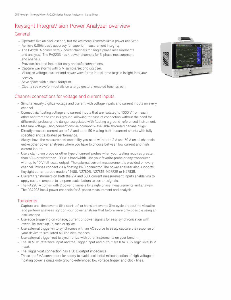
General – Operates like an oscilloscope, but makes measurements like a power analyzer. – Achieve 0.05% basic accuracy for superior measurement integrity. – The PA2201A comes with 2 power channels for single phase measurements and analysis. The PA2203 has 4 power channels for 3-phase measurement and analysis.
– Provides isolated inputs for easy and safe connections. – Capture waveforms with 5 M sample/second digitizer. – Visualize voltage, current and power waveforms in real-time to gain insight into your device.
– Save space with a small footprint. – Clearly see waveform details on a large gesture-enabled touchscreen.
Channel connections for voltage and current inputs– Simultaneously digitize voltage and current with voltage inputs and current inputs on every
channel.– Connect via floating voltage and current inputs that are isolated to 1000 V from each
other and from the chassis ground, allowing for ease of connection without the need for differential probes or the danger associated with floating a ground-referenced instrument.
– Measure voltage using connections via commonly-available shrouded banana plugs.– Directly measure current up to 2 A and up to 50 A using built-in current shunts with fully
specified and calibrated performance. – Always have the measurement capability you need with both 2 A and 50 A on all channels
unlike other power analyzers where you have to choose between low current and high current inputs.
– Use a clamp-on probe or other type of current probes when your testing requires greater than 50 A or wider than 100 kHz bandwidth. Use your favorite probe or any transducer with up to 10 V full-scale output. The external current measurement is provided on every channel. Probes connect via a floating BNC connector. The power analyzer also supports Keysight current probe models 11488, N2780B, N2781B, N2782B or N2783B.
– Current transformers on both the 2 A and 50 A current measurement inputs enable you to apply custom ampere-to-ampere scale factors to current signals.
– The PA2201A comes with 2 power channels for single phase measurements and analysis. The PA2203 has 4 power channels for 3-phase measurement and analysis.
Transients – Capture one-time events (like start-up) or transient events (like cycle dropout) to visualize
and perform analyses right on your power analyzer that before were only possible using an oscilloscope.
– Use edge triggering on voltage, current or power signals for easy synchronization with event like start-up, in-rush or spikes.
– Use external trigger-in to synchronize with an AC source to easily capture the response of your device to simulated AC line disturbances.
– Use external trigger-out to synchronize with other instruments on your bench. – The 10 MHz Reference input and the Trigger input and output are 0 to 3.3 V logic level (5 V
max). – The Trigger-out connection has a 50 Ω output impedance. – These are SMA connectors for safety to avoid accidental misconnection of high voltage or
floating power signals onto ground-referenced low voltage trigger and clock lines.
Keysight IntegraVision Power Analyzer overview
06 | Keysight | IntegraVision PA2200 Series Power Analyzers - Data Sheet
Measurements – Simplify configuration and purchase with all measurement functions included, unlike other
power analyzers where you must configure your power analyzer from a long and confusing set of options.
– Choose from 29 pre-defined cursor measurements on waveforms including peak-to-peak, rise time, frequency, and area under waveform.
– Display up to 10 automatic measurements at a time along with measurement statistics. – Gate measurements by manually placing the cursors on the waveform or by auto select,
where cursors track the waveform. – Measure true rms values of voltage and current, even if your waveform is non-sinusoidal
and has DC offsets. – Measure power quality: Watts, VA, VAR, power factor, phase angle, voltage crest factor,
and current crest factor. – Measure power and efficiency. – Perform frequency domain analysis using FFT and harmonic measurements. – Measure voltage harmonics, current harmonics, and power harmonics up to 250 orders. – Simultaneously view harmonic data and capture/display time domain signal data for volt-
age, current or power. – Display harmonics as a table of exact order values and as a bar chart to visualize the rela-
tive size of the harmonics. – Measure total harmonic distortion (THD) following the IEC method. – Check harmonics with IEC 61000-3-2 Class A, B, C, and D limits. – Use math functions to operate on captured waveforms to create new user-defined mea-
surements, such as i2t to calculate thermal energy to properly size a fuse. – Use the operators on math functions (can nest math functions):
– Add, subtract, multiply, divide – Differentiate, integrate – FFT – Ax + B – Squared, square root – Absolute value – Common logarithm, natural logarithm – Exponential, base 10 exponential
– Perform integrated energy measurements of Ampere-Hours (AH) and Watt-Hours (WH) to determine total AC and DC energy consumption in order to analyze energy consumed from the grid or energy associated with battery charging/discharging operations.
– Compare live waveforms with reference waveforms for up to four reference waveforms that you can capture and store in nonvolatile reference waveform memory.
User interface – Use pinch, zoom, scroll ― the same intuitive actions found on tablets and smartphones –
on the large gesture-enabled touchscreen. – Disable touch and use hardkeys/softkeys when operation via touch is not preferred. – Select from eight different display formats to visually highlight the information you need to
gain fast insights. – Create custom waveform labels and screen annotations to make documentation easier. – Save states and recall them later for fast jumps to commonly used setups. – Quickly find signals and automatically configure display settings with Autoscale button. – Easily save data and screen images on a USB flash drive connected via the convenient USB
port on the front panel. – Press and hold any button for context sensitive help. A full user manual is built-in as well.

07 | Keysight | IntegraVision PA2200 Series Power Analyzers - Data Sheet
Datalogger- Capture data for off-line analysis and test archival.- Set logging interval from 50ms to 1 day- Set logging duration from 1s to 1 year
Remote IO- Communicate remotely over your choice of USB and LAN interfaces. Both are standard for
simplified ordering with nothing extra to buy. – Control remotely over LAN via a standard web browser. The IntegraVision power analyzer
contains a web server that provides a webpage containing a graphical front panel representation of the PA2201A/PA2203A front panel. The WebGUI operation is identical to operating the real front panel on the PA2201A/PA2203A.
Safety, installation and support – Operate with safe connections provided by an integrated safety cover on current
connections. – Access direct current measurements made via removable connector (Keysight part
number 5067-6088 or Phoenix connector type PC 16/ 3-STF-10,16, Phoenix part number 1967469).
– CAT II inputs are rated to 1000 V. – Provides NISPOM compliant data sanitization. – Universal AC input including 400 Hz AC operation. – Mount in standard test rack. (Rack mount kit coming summer of 2015 – check www.key-
sight.com/find/PA2200Series for availability and for ordering information). – Calibrate once per year, unlike other power analyzers whose published specs are for 6
months and for operation beyond 6 months, require adjustment of specs. – Easily upgrade firmware via front panel USB. Download latest firmware files from www.
keysight.com/find/PA2200Series. Simply save the firmware update file on a USB drive and use the utility menu to update your IntegraVision power analyzer.
08 | Keysight | IntegraVision PA2200 Series Power Analyzers - Data Sheet
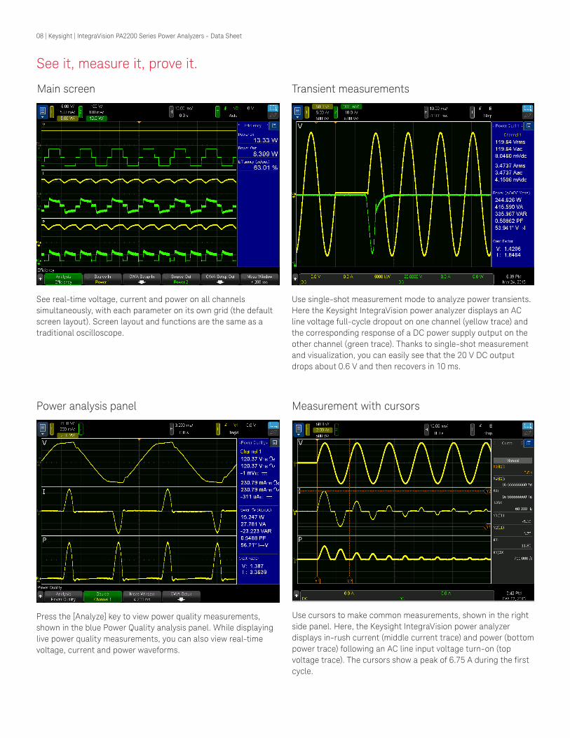
See it, measure it, prove it.
See real-time voltage, current and power on all channels simultaneously, with each parameter on its own grid (the default screen layout). Screen layout and functions are the same as a traditional oscilloscope.
Press the [Analyze] key to view power quality measurements, shown in the blue Power Quality analysis panel. While displaying live power quality measurements, you can also view real-time voltage, current and power waveforms.
Use single-shot measurement mode to analyze power transients. Here the Keysight IntegraVision power analyzer displays an AC line voltage full-cycle dropout on one channel (yellow trace) and the corresponding response of a DC power supply output on the other channel (green trace). Thanks to single-shot measurement and visualization, you can easily see that the 20 V DC output drops about 0.6 V and then recovers in 10 ms.
Use cursors to make common measurements, shown in the right side panel. Here, the Keysight IntegraVision power analyzer displays in-rush current (middle current trace) and power (bottom power trace) following an AC line input voltage turn-on (top voltage trace). The cursors show a peak of 6.75 A during the first cycle.
Main screen Transient measurements
Power analysis panel Measurement with cursors

09 | Keysight | IntegraVision PA2200 Series Power Analyzers - Data Sheet
See it, measure it, prove it.
Perform harmonic analysis on voltage or current. Both the time domain waveform (yellow trace) and the harmonic table are simultaneously displayed.
In addition to the harmonics table, simultaneously view a bar graph of the harmonic orders to visually identify high value harmonics.
Choose from 8 different screen layouts of the voltage, current and power waveforms. Here, the Keysight IntegraVision power analyzer is displaying an enlarged view of voltage and current on the same grid to highlight the time relationship between voltage and current.
Quickly check harmonics with IEC 61000-3-2 limits (Classes A, B, C, and D)
Harmonic measurements with graph User selectable screen layouts
Harmonic measurements with bar graph On-screen keyboard with touch
10 | Keysight | IntegraVision PA2200 Series Power Analyzers - Data Sheet
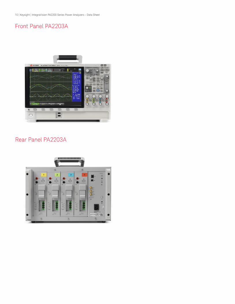
Front Panel PA2203A
Rear Panel PA2203A

11 | Keysight | IntegraVision PA2200 Series Power Analyzers - Data Sheet
USB
LAN
Trigger in/outDirect current input:
2 internal shunts for 2 Arms and 50 Arms
Integratedsliding safety
cover
IsolatedBNC input
for externalcurrent
probes andtransducers
up to 10 Vfull scale
Voltageinputs
When measuring current with the direct current input, wiring to the DUT is connected on a removable connector, allowing you to quickly remove the wires for fast reconfiguration.
The wires are inserted into the removable side of the connector and screws secure the wires inside of the connector.
Rear Panel PA2201A

12 | Keysight | IntegraVision PA2200 Series Power Analyzers - Data Sheet
Key Applications
Electrical Power Conversion SystemsExamples:
– AC/DC power supplies – DC/AC inverters – DC/DC converters – Solar inverters – Hybrid Electric Vehicles (HEV), Electric Vehicles (EV), and Plug-in Hybrid Electric Vehicles
(PHEV) inverters
Important power converter measurements: – Power consumption – Efficiency – Harmonics and THD – Response to dynamic conditions – Startup characterization
Like traditional power analyzers, IntegraVision can provide you with fast and accurate measurement of common parameters like power consumption and efficiency and harmonics.
Visualizing and measuring dynamic conditions is important due to the increasing complexity of control systems. IntegraVision can capture voltage, current and power waveforms over specific periods of time. Placing cursors on the captured waveforms will enable you to visualize and measure power consumption across a wide range of modes, from sleep to full activity, and all the transient states in between.
IntegraVision’s single-shot measurement capability simultaneously captures voltage and current, so you can visualize and measure critical one-time events, like the response of your device to dynamic conditions, such as an unstable AC line. Using trigger-in, you can synchronize your AC source with IntegraVision and capture power converter response to cycle dropouts, line spikes, sag/surge and other AC line distortions. Similarly, you can capture your DUT’s response to other time-varying events, like a step change in load or other dynamic loading conditions. You can also visualize and measure events like start-up, in-rush current, and calculate i2t for fuse sizing. IntegraVision’s direct high-accuracy measurement of your converter’s output allows you to visualize and measure transient response, settling time, and other power supply performance characteristics. These measurements pose challenges for ground-referenced 8-bit or 10-bit scopes which don’t have enough vertical accuracy or resolution to measure load regulation or to resolve narrow settling bands.

13 | Keysight | IntegraVision PA2200 Series Power Analyzers - Data Sheet
Energy StorageExamples:
– UPS – Battery powered backup and standby systems – Battery chargers – Charging stations – Battery management systems – Energy storage systems
Important energy storage measurements: – Capacity – Runtime – Cross over time – Accumulated energy in/out
IntegraVision measures instantaneous positive and negative values of current flowing into and out of the DUT. Data is captured at up to 5 M samples/second and values are integrated to accumulate amp-hours and watt-hours. This high speed integration function makes it possible to more accurately measure the power consumption of devices for which power usage and power direction of flow fluctuates greatly. Thus, battery capacity can be calculated and battery run-time can be determined based on real loading conditions as you observe current flow, power flow, and energy increase/decrease in the storage devices.
For UPS and battery backup systems, thanks to IntegraVision’s single-shot measurement capability, single events and cross-over time from AC line to battery backup can be captured and analyzed.
Electrical and Electro-Mechanical SystemsExamples:
– Lighting – Appliances – Industrial machines – Robotics
Important measurements for electrical/electro-mechanical systems: – Instantaneous and peak power – Power consumption – Harmonics and THD – Transients and dynamic current consumption
Testing of lighting devices often involves measurement voltage waveforms, current waveforms and THD, because distortion in voltage and current waveforms is becoming more prevalent due to the increasing complexity of control systems.
For appliances and industrial machines, you need to measure dynamic current and power over individual actions (such as a cycle on a machine or a single motion of a robot). During actual operating conditions, the time to accelerate/decelerate motors or to activate sub-systems can range from several hundred milliseconds to several seconds. IntegraVision gives you insight into power consumption and DUT behavior for short events (milliseconds) or over longer power cycles (seconds, minutes, hours or even days).

14 | Keysight | IntegraVision PA2200 Series Power Analyzers - Data Sheet
Overview
Basic accuracy (50/60 Hz) 0.05% of reading
Best power accuracy (50/60 Hz) 0.1% of reading
Power Channels (Voltage and Current) PA2201A: 2 Channels, PA2203A: 4 Channels
Voltage Measurement Bandwidth (-3 dB) 2.5 MHz (-3 dB)
Current Measurement Bandwidth (2 A or 50 A Input) 100 kHz (-3 dB)
Current Measurement Bandwidth (External Input) 2.5 MHz (-3 dB)
Maximum Voltage 1000 Vrms (2000 V peak)
Maximum Current Direct input: 2 Arms (6 A peak) or 50 Arms (100 A peak)
External transducer: 10 Vrms (30 V peak)
Record Size Maximum 1.5 M points on each waveform simultaneously
Digitizing Speed Maximum 5 M samples/second at 16 bits on each waveform simultaneously
Display size and type 12.1- inch capacitive multi-touch/gesture enabled display
Power Channels (Voltage and Current)
Voltage Connector Safety Banana Plug
Maximum Voltage 1000 Vrms, 2000 Vpeak
Input Impedance 2 M Ω || 12.5 pF
Ranges 5 V, 10 V, 20 V, 50 V, 100 V, 200 V, 500 V, 1000 V
Current Directly Connected Connector Pluggable Terminal Block, Phoenix Contact PN: 1967469
Maximum Current 2 Arms, 6 A peak or 50 Arms, 100 A peak
Input Impedance 2 A input: 60 mΩ + 0.10 µH
50 A input: 6 mΩ + 0.06 µH
Ranges 2 A input: 10 mA, 20 mA, 50 mA, 100 mA, 200 mA, 500 mA, 1 A, 2 A
50 A input: 200 mA, 500 mA, 1 A, 2 A, 5 A, 10 A, 20 A, 50 A
External Transducer Connector Isolated BNC
Maximum Input Voltage 10 Vrms, 30 V peak
Input Impedance 100 kΩ || 100 pF
Ranges 50 mV, 100 mV, 200 mV, 500 mV, 1 V, 2 V, 5 V, 10 V
Crest Factor 3 at full-scale (Unless in conflict with maximum input ratings) Maximum Crest Factor of 30 at 10% of full scale
Current Input Protection Internal current shunt measurement paths are not fused. Current limit protection (fuse or breaker) and appropriate wire sizing should be provided by the user. Currents in excess of 140% of the rated rms currents may cause permanent damage to the current measurement shunts. An internal protection mechanism is provided for the 2A shunt to avoid damage due to mis-wiring, but it should not be relied upon in situations where higher than 2 Arms currents are expected.
Isolation Voltage and current terminals are isolated from earth ground to 1000 V CAT II rating. Voltage is isolated from current with 1000 V CAT II rating
15 | Keysight | IntegraVision PA2200 Series Power Analyzers - Data Sheet
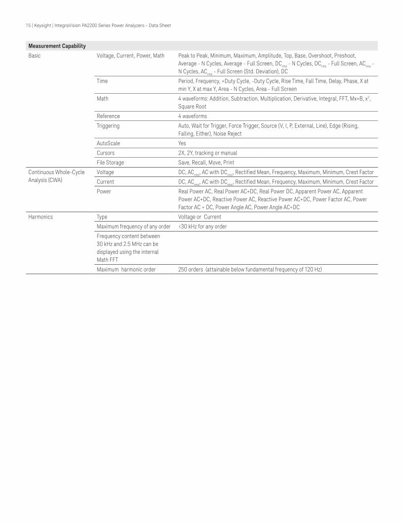
Measurement Capability
Basic Voltage, Current, Power, Math Peak to Peak, Minimum, Maximum, Amplitude, Top, Base, Overshoot, Preshoot, Average - N Cycles, Average - Full Screen, DCrms - N Cycles, DCrms - Full Screen, ACrms - N Cycles, ACrms - Full Screen (Std. Deviation), DC
Time Period, Frequency, +Duty Cycle, -Duty Cycle, Rise Time, Fall Time, Delay, Phase, X at min Y, X at max Y, Area - N Cycles, Area - Full Screen
Math 4 waveforms: Addition, Subtraction, Multiplication, Derivative, Integral, FFT, Mx+B, x2, Square Root
Reference 4 waveforms
Triggering Auto, Wait for Trigger, Force Trigger, Source (V, I, P, External, Line), Edge (Rising, Falling, Either), Noise Reject
AutoScale Yes
Cursors 2X, 2Y, tracking or manual
File Storage Save, Recall, Move, Print
Continuous Whole-Cycle Analysis (CWA)
Voltage DC, ACrms, AC with DCrms, Rectified Mean, Frequency, Maximum, Minimum, Crest Factor
Current DC, ACrms, AC with DCrms, Rectified Mean, Frequency, Maximum, Minimum, Crest Factor
Power Real Power AC, Real Power AC+DC, Real Power DC, Apparent Power AC, Apparent Power AC+DC, Reactive Power AC, Reactive Power AC+DC, Power Factor AC, Power Factor AC + DC, Power Angle AC, Power Angle AC+DC
Harmonics Type Voltage or Current
Maximum frequency of any order <30 kHz for any order
Frequency content between 30 kHz and 2.5 MHz can be displayed using the internal Math FFT
Maximum harmonic order 250 orders (attainable below fundamental frequency of 120 Hz)

16 | Keysight | IntegraVision PA2200 Series Power Analyzers - Data Sheet
1. Specifications are valid for operating temperature of 23 ±5C, Humidity of 20 to 80% RH with at least 60 minutes of warm-up. Valid for 1 year from calibration. Input must be sinusoidal with amplitude between 10% to 110% of range with no common mode signal, with a power factor of 1. Measurement technique must be Continuous Whole-Cycle Analysis (CWA) with interval greater than or equal to 200 ms. Specifications for inputs beyond g70.8 10x V Hz are characteristics. Specifications for frequencies between DC to 10 Hz and above 1 MHz are characteristics. Internal current and power with internal current specifications above 10 kHz are characteristics. Outside of 23 ± 5C, use the following % of Reading + % of Range specification adder.
2. For measurements above 100 kHz, anti-aliasing (AA) filter must be turned off. If AA filter is on, add an additional ( )g 20.0004 times % of Readingf . For all specifications dependent on frequency, use frequency (f) in kHz.
3. To meet the DC accuracy in the table, a zero compensation process must have occurred within the past hour, or within 2 C ambient temperature change. A zero compensation process happens automatically any time the range is changed, or when a zero process is explicitly requested via the user interface. Otherwise, add 0.1% of range.
4. In the specification above, Rtrans is equal to the Voltage per Ampere transducer gain, and Ntrans is the Ampere per Ampere turns ratio of the current transformer. Voltage Reading term is the RMS voltage measurement from the same power channel.
5. The -3 dB BW of voltage and transducer inputs is 2.5 MHz anti-aliasing is off.6. If current greater than 20 Arms is applied to the 50 A input, you must wait at least 10 minutes to get full accuracy below 20 Arms. This is due to self heating of
the shunt. 7. Common mode signal applied to the current terminals can affect the accuracy of the measurement. To calculate the impact of the common mode, multiply
the ACrms common mode voltage by the frequency of the common mode signal and then multiply by the spec adder below. For the effects on power accuracy, multiply this error term by Macrms.
8. Use these specs for P, Q and S. Range for a power measurement is defined as (Voltage Range) x (Current Range).9. Apply this error to power P and reactive power Q. For power Factor (λ) in between 0 and 1, use the formula:
l= gg 20 1 1 % RangeerrP f. and l= ggerrQ 0.1 f times % of Range 10. Power factor Accuracy: ( ) lg 20.005 0.00+ 18 1f 11. Phase Accuracy: ( )+ g0.03 0.054 f degrees
Accuracy
Accuracy Specifications for V, I, P, Q, S, λ, phase: ± (% Reading + % Range + Fixed Term) 1 Valid for 1 year from calibration
Frequency
DC 3 - 10 Hz 10 Hz-40 Hz 40 Hz-100 Hz 100 Hz-1 kHz 1 kHz-10 kHz 10 kHz-100 kHz 2 100 kHz-1 MHz 2
Voltage 4 %Reading + %Range 0.05 + 0.05 0.06 + 0.05 0.05 + 0.05 0.05 + 0.05 0.1 + 0.05 0.8 + 0.4 0.008 x f + 0.5
Fixed Term 100 µV
Current 4 (External Input)
%Reading + %Range 0.05 + 0.05 0.06 + 0.05 0.05 + 0.05 0.05 + 0.05 0.1 + 0.05 0.8 + 0.4 0.008 x f + 0.5
Fixed Term 100 µV (1/Rtrans)
Current 6,7 (Directly Connected 2 A and 50 A Inputs)
%Reading + %Range 0.08 + 0.04 0.08 + 0.03 0.08 + 0.03 0.1 + 0.05 0.5 + 0.2 (0.05 x f) + 0.4
UnspecifiedFixed Term 2 A 0.05 mA
Fixed Term 50 A 1 mA
Power 8,9 (External Current Input)
%Reading + %Range 0.08 + 0.08 0.08 + 0.08 0.08 + 0.08 0.08 + 0.08 0.15 + 0.08 1.6 + 0.7Unspecified
Fixed Term 100 µV Rtrans Voltage Reading 4
Power 8,9 (Directly Connected Current Input)
%Reading + %Range 0.1 + 0.05 0.1 + 0.05 0.1 + 0.05 0.1 + 0.05 0.5 + 0.05 (0.05 x f) + 0.7
UnspecifiedFixed Term 2 A 0.05 mA Rtrans Voltage Reading 4
Fixed Term 50 A 1 mA Rtrans Voltage Reading 4
Notes:
For all specs dependent on frequency, use frequency (f) in kHz.
Ranges: Voltage: 5 V, 10 V, 20 V, 50 V, 100 V, 200 V, 500 V, 1000 V2 A input: 10 mA, 20 mA, 50 mA, 100 mA, 200 mA, 500 mA, 1 A, 2 A50 A input: 200 mA, 500 mA, 1 A, 2 A, 5 A, 10 A, 20 A, 50 AExternal Transducer input: 50 mV, 100 mV, 200 mV, 500 mV, 1 V, 2 V, 5 V, 10 V
V, ITemp Coefficient 0.005 + 0.005 Per degree outside of 23 ± 5C
DC Temp Coefficient 0.005 + 0.020 Per degree outside of 23 ± 5C
P, Q, STemp Coefficient 0.01 + 0.01 Per degree outside of 23 ± 5C
DC Temp Coefficient 0.01 + 0.02 Per degree outside of 23 ± 5C
2 A 2 nA / VHz
50 A 10 nA / VHz

17 | Keysight | IntegraVision PA2200 Series Power Analyzers - Data Sheet
Continuous Whole-cycle Analysis (CWA) Frequency Measurements
1. For signals lower than the values following table, add 0.2%
2. For current below 5 mA on the 2 A input and 100 mA on the 50 A input, frequency measurement accuracy is unspecified below 10x the minimum measurable frequency listed above.
3. The above specifications are valid for sinusoidal input signals larger than 10% of range using CWA frequency measurement.
Measurement Characteristics
THD -75 dBc at full scale for all inputs (<10 kHz)
dV/dt Common Mode relative to earth without resetting instrument
>25 kV/ms
Trigger Jitter ±100 ns Input and Output
Noise Floor 1% of range. On directly connected current inputs, add 5 mA (2 A connection) and 50 mA (50 A connection).
Voltage measurement capacitance to earth:
<130 pF
Current measurement capacitance to ground:
<130 pF
Display Characteristics
Display 12.1-inch capacitive multi-touch/gesture enabled
Resolution 800 (H) x 600 (V) pixel format (screen area)
Intensity gradation 256 intensity levels
Display format Configurable
Connectivity
USB 2.0 hi-speed host port Two USB 2.0 hi-speed host ports on front panel for memory devices and peripherals (e.g. keyboard, mouse, printer)
USB 2.0 hi-speed device port One USB 2.0 hi-speed device port on rear panel. USB Test & Measurement Class (USBTMC) compatible.
LAN port 10/100/1000 Base-T port on rear panel
Web remote control VNC Web interface (via major Web browsers)
10 MHz Reference Input Earth referenced SMA connector on rear panel. 0 to 3.3 V logic level (5 V Max.)
Trigger In Earth referenced SMA connector on rear panel. 0 to 3.3 V logic level (5 V Max.)
Trigger Out Earth referenced SMA connector on rear panel. 0 to 3.3 V logic level, 50 Ω output impedance.
Accuracy: 0.05%
Measurement Limits vs CWA Window Length:
CWA Window Length Min Measurable Freq
50 ms 200 Hz
100 ms 100 Hz
200 ms 45 Hz
500 ms 20 Hz
1 s 10 Hz
2 s 5 Hz
5 s 2 Hz
10 s 1 Hz
20 s 0.5 Hz
External Current Input 10 mV
2 A 20 mA
50 A 500 mA

18 | Keysight | IntegraVision PA2200 Series Power Analyzers - Data Sheet
General environmental characteristics
Power line consumption Maximum 180 VA
Power voltage range 100-240 V, 50/60 Hz ±10%; 100-120 V, 50/60/400 Hz; auto-ranging
Temperature Operating 0 to +40 °C
Non-operating -40 to +70 °C
Humidity Operating 80% RH (non-condensing) at 40 °C
Altitude Operating Up to 3,000 m (15,000 ft)
Non-operating Up to 15,300 m (50,000 ft)
Acoustic power Typical < 40 dBa, worst case noise <56 dBa
Warm-up Time 60 minutes
Electromagnetic compatibility Compliant with EMC Directive (2004/108/EC),
IEC 61326-1:2012/EN 61326-1:2013 Group 1 Class A
Canada: ICES-001:2004
Australia/New Zealand: AS/NZS
South Korea KC mark
Safety UL 61010-1 3rd edition, CAN/CSA_22.2 No.61010-1-12, IEC 61010-1:2010 3 rd edition
IEC 61010-2-030: 2010, CAT II
Vibration Based on IEC 60068
Shock Based on IEC 60068
Dimensions 426 mm W x 308 mm H x 272.8 mm D (16.8 in W x 12.1 in H x 10.7 in D)
Weight PA2201A: Net: 11.4 kg (25.2 lbs), Shipping: 12.8 kg (28.3 lbs)
PA2203A: Net: 12.3 kg (27.2 lbs), Shipping: 13.7 kg (30.3 lbs)
Ordering Information
PA2201A for 2 power channels (single phase measurements and analysis)PA2203A for 4 power channels (3-phase measurements and analysis).

19 | Keysight | M9037A PXIe Embedded Controller - Data Sheet
For more information on Keysight Technologies’ products, applications or services, please contact your local Keysight office. The complete list is available at:www.keysight.com/find/contactus
Americas Canada (877) 894 4414Brazil 55 11 3351 7010Mexico 001 800 254 2440United States (800) 829 4444
Asia PacificAustralia 1 800 629 485China 800 810 0189Hong Kong 800 938 693India 1 800 11 2626Japan 0120 (421) 345Korea 080 769 0800Malaysia 1 800 888 848Singapore 1 800 375 8100Taiwan 0800 047 866Other AP Countries (65) 6375 8100
Europe & Middle EastAustria 0800 001122Belgium 0800 58580Finland 0800 523252France 0805 980333Germany 0800 6270999Ireland 1800 832700Israel 1 809 343051Italy 800 599100Luxembourg +32 800 58580Netherlands 0800 0233200Russia 8800 5009286Spain 800 000154Sweden 0200 882255Switzerland 0800 805353
Opt. 1 (DE)Opt. 2 (FR)Opt. 3 (IT)
United Kingdom 0800 0260637
For other unlisted countries:www.keysight.com/find/contactus(BP-9-7-17)
DEKRA CertifiedISO9001 Quality Management System
www.keysight.com/go/qualityKeysight Technologies, Inc.DEKRA Certified ISO 9001:2015Quality Management System
Evolving Since 1939Our unique combination of hardware, software, services, and people can help you reach your next breakthrough. We are unlocking the future of technology. From Hewlett-Packard to Agilent to Keysight.
myKeysightwww.keysight.com/find/mykeysightA personalized view into the information most relevant to you.
http://www.keysight.com/find/emt_product_registrationRegister your products to get up-to-date product information and find warranty information.
Keysight Serviceswww.keysight.com/find/serviceKeysight Services can help from acquisition to renewal across your instrument’s lifecycle. Our comprehensive service offerings—one-stop calibration, repair, asset management, technology refresh, consulting, training and more—helps you improve product quality and lower costs.
Keysight Assurance Planswww.keysight.com/find/AssurancePlansUp to ten years of protection and no budgetary surprises to ensure your instruments are operating to specification, so you can rely on accurate measurements.
Keysight Channel Partnerswww.keysight.com/find/channelpartnersGet the best of both worlds: Keysight’s measurement expertise and product breadth, combined with channel partner convenience.
www.keysight.com/find/PA2200Series
This information is subject to change without notice.© Keysight Technologies, 2017Published in USA, December 1, 20175992-0324ENwww.keysight.com