Embed Size (px)
Citation preview

44 Warner Electric 800-825-6544 P-771-WE 6/11
Tension ControlsSelection Guide
Selecting the Correct Tension ControlSelecting the correct tension control isas important as selecting the propertension clutch or brake. As the controlis the heart of the system which pro-vides the necessary controlling functionin the application, selecting the wrongcontrol or inadequate control can be asbad as incorrectly sizing the mechani-cal portion of the system.
Normally control selection can bevery simple if a few simple questionscan be answered regarding the appli-cation. By doing so, selection can bevery easy and painless.
Control – Quick Selection Guide
Selection StepsThe following steps outline a simpleway of selecting the proper control sys-tem for the application.
1. Determine the type of system that isto be used. Will the system be loadcell, dancer, or open loop analogcontrol?
2. Next, determine the type of brake orclutch system that the control will beused with. Will this be an electric orpneumatic system?
3. Using the Quick Selection Chart,determine which models may besuitable for the application.
Once the determination of thecontrol/controls has been made for theapplication, review the specificationsfor the various controls to determinethe characteristics and features thatbest suit the application and your requirements.
Mechanical ElementsOnce the control has been selected, besure to check that it will work with thebrake or clutch previously selected.This can be determined from the spe-cific technical specification for the con-trol selected. Remember, not all con-trols will work with all clutches andbrakes.
If the control selected will not oper-ate the controlling device selected, i.e.,clutch or brake, then a different controlmust be selected.
System Type
Open Loop Closed Loop
Model Manual Analog Air orNumber Output Voltage Adjust Input Adjust Dancer Load Cell Electric Page
MCS2000 0±10 (2 channel)● ● ● ● Air/Electric 46
(0–20mA)
*TCS-200 0–24 ● ● Electric 56
TCS-200-1 0–24 ● ● Electric 56
TCS-200-1H 0–24 ● ● Electric 56
MCS-203 0–24 ● Electric 61
MCS-204 0–24 ● ● Electric 57
MCS-207 0–10 (1–50mA) ● Air 63
MCS-208 0–10 (1–50mA) ● ● Air 59
TCS-210 0–24 (48) ● Electric 62
TCS-220 0–24 (48) ● ● Electric 58
TCS-310 0–24 (48) (2 channel) ● Electric 64
TCS-320 0–24 (48) (2 channel) ● ● Electric 60
*For new applications, we recommend the TCS-200-1 or TCS-200-1H.
KALATEC AUTOMACAO LTDA
MATRIZ (19)3045-4900 SAO PAULO(11)5514-7680 JOINVILLE(47)3425-0042

P-771-WE 6/11 Warner Electric 800-825-6544 45
Tension ControlsSelection Guide
MCS2000
TCS-210
MCS-207
MCS-208
Control Description Page Number
MCS-203
Fully digital control, PLC compatible, which can operate in both open(analog input follower) or closed (dancer or load cell) mode. Directlycontrols electric clutches and brakes, and air brakes via anelectric/pneumatic transducer. Control has two output channels withfully programmable splice logic. Can also be used as a digital frontend to an analog drive.
46
56
56
61
57
63
59
62
58
64
60
Economical closed loop dancer control for all 24V brakes and clutches.Has reserve 48V supply for enhanced E-stop torque with certain brakes.
For use with MTB Series electric brakes (page 68).
Closed loop dancer control for 24V electric clutches and brakes.
For use with TB Series, ATTC and ATTB Series and Magnetic Particleclutches and brakes (page 68).
MCS-204 Analog control for 24V electric clutches and brakes. Manual control,or analog (0–10V or 4–20mA) signal.
For use with TB Series, ATTC and ATTB Series and Magnetic Particleclutches and brakes (page 68).
Economical closed loop dancer control especially configured for airbrakes. Provides a 0–10V or 4–20mA output to E/P transducers.
For use with Pneumatic brakes (page 68).
Economical open loop analog control especially configured for airbrakes. Provides manual control, or accepts analog input (0–10V or4–20mA). Same output as MCS-207.
For use with Pneumatic brakes (page 68).
TCS-200 Inexpensive analog control with manual or remote follower adjust forelectric brakes. Also accepts roll follower potentiometer input. Requires24-30 VAC input.
For use with MTB Series electric brakes (page 68).
Extremely versatile and economical open loop control for all 24V electricbrakes and clutches. Can be used for manual adjust, or will follow ananalog (0–10V, 4–20mA) input, such as from an ultrasonic sensor or PLC.
For use with MTB, TB and ATTB Series and magnetic particle electricbrakes. (page 68)
TCS-220 Analog control for 24V electric clutches and brakes. Manual adjust, or follows analog (0–10V or 4–20mA) input. Reserve 48V overexcite for E-stops.
For use with MTB Series electric brakes (page 68).
Dancer splicer control (two output channels) for 24V electric brakes.Full splicing logic, and 48V overexcite for E-stops.
For use with MTB Series electric brakes (page 68).
TCS-310
Analog splicer control (two output channels) for 24V electric brakes.48V overexcite for E-stops.
For use with MTB Series electric brakes (page 68).
TCS-320
TCS-200-1TCS-200-1H
KALATEC AUTOMACAO LTDA
MATRIZ (19)3045-4900 SAO PAULO(11)5514-7680 JOINVILLE(47)3425-0042

46 Warner Electric 800-825-6544 P-771-WE 6/11
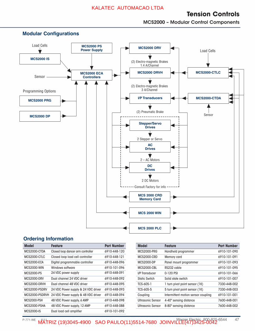
Tension ControlsMCS2000 – Modular Control Components
Flexible modular design is the key to trouble-free web tension control!
■ Auto scaling of sensors■ Capable of open-loop operation with an
ultrasonic sensor■ Splicing capability■ Windows programming software■ Automatic voltage range of AC input
(95-264 VAC)■ Short-circuit protection■ Quick-disconnect wiring terminals■ Capable of controlling dual channel
rewind or unwind ■ Automatic PID correction - from analog
inputs■ 2 x 16 backlit LCD display for program-
ming and parameter readout
Difficult setups with potentiometeradjustments are no longer a problem.The MCS2000 Web Tension Controlleris easily programmed with only fourpush buttons on a panel-mounted pro-grammer; a handheld programmer; ora Windows driven software package.All programmers employ a simplemenu driven format. The unit can also“talk” to a PLC via the RS232 cable.
The power supply AC input auto-ranges from 95 to 264 VAC to avoidany match-up problems. The unit canbe used in both open-loop and closed-loop systems. It can also be configuredin an “open plus super-imposed/closed-loop design for very precisetension control applications.
Two types of amplifiers are avail-able for powering electro-magnetic
The MCS2000 Digital Web Tension Controller handles all winding and unwinding applications,either brake or motor operated.
brakes. The amplifiers have outputs forcontrolling two high-power brakes at1.4 or 3 Amps per channel, continuousfor each brake.
The MCS2000 modules are housedin metal enclosures designed for snap-fit assembly, eliminating screw attach-ment (patent applied for). All compo-nents are on printed circuit boards.Wiring connections are made withquick-disconnect screw terminals.
Features■ Modular system■ Easy to program■ Plug-in memory card for saving
parameters■ Programmable in English or French■ PLC compatible■ Optically isolated inputs and outputs■ Dual output in either current or voltage
operation mode
KALATEC AUTOMACAO LTDA
MATRIZ (19)3045-4900 SAO PAULO(11)5514-7680 JOINVILLE(47)3425-0042
P-771-WE 6/11 Warner Electric 800-825-6544 47
Tension ControlsMCS2000 – Modular Control Components
Modular Configurations
Model Feature Part NumberMCS2000-CTDA Closed loop dancer arm controller 6910-448-120
MCS2000-CTLC Closed loop load cell controller 6910-448-121
MCS2000-ECA Digital programmable controller 6910-448-096
MCS2000-WIN Windows software 6910-101-096
MCS2000-PS 24 VDC power supply 6910-448-091
MCS2000-DRV Dual channel 24 VDC driver 6910-448-092
MCS2000-DRVH Dual channel 48 VDC driver 6910-448-095
MCS2000-PSDRV 24 VDC Power supply & 24 VDC driver 6910-448-093
MCS2000-PSDRVH 24 VDC Power supply & 48 VDC driver 6910-448-094
MCS2000-PSH 48 VDC Power supply, 6 AMP 6910-448-098
MCS2000-PSHA 48 VDC Power supply, 12 AMP 6910-448-088
MCS2000-IS Dual load cell amplifier 6910-101-092
Model Feature Part NumberMCS2000-PRG Handheld programmer 6910-101-090
MCS2000-CRD Memory card 6910-101-091
MCS2000-DP Panel mount programmer 6910-101-093
MCS2000-CBL RS232 cable 6910-101-095
I/P Transducer 0-120 PSI 6910-101-066
Static Switch Solid state switch 6910-101-007
TCS-605-1 1 turn pivot point sensor (1K) 7330-448-002
TCS-605-5 5 turn pivot point sensor (1K) 7330-448-003
Coupling Intermittent motion sensor coupling 6910-101-001
Ultrasonic Sensor 4-40" sensing distance 7600-448-001
Ultrasonic Sensor 8-80" sensing distance 7600-448-002
Ordering Information
MCS 2000 CRDMemory Card
Load Cells
MCS2000 IS
MCS2000 ECAControllersSensor
MCS2000 PSPower Supply
MCS2000 DRV
MCS2000 DRVH
I/P Transducers
Stepper/ServoDrives
ACDrives
DCDrives
MCS 2000 WIN
Load Cells
MCS2000-CTDA
Sensor
MCS2000 PRG
Programming Options
MCS2000 DP
(2) Electro-magnetic Brakes1.4 A/Channel
(2) Electro-magnetic Brakes3 A/Channel
(2) Pneumatic Brake
2 Stepper or Servo
2 – AC Motors
MCS 2000 PLC
MCS2000-CTLC
2 DC Motors
Consult Factory for info
KALATEC AUTOMACAO LTDA
MATRIZ (19)3045-4900 SAO PAULO(11)5514-7680 JOINVILLE(47)3425-0042

48 Warner Electric 800-825-6544 P-771-WE 6/11
Tension ControlsMCS2000 – Modular Control Components
Application Examples
Dancer Arm Control
Magnetic ParticleBrake
PSDRV Power Supply and Drive
CTDA
DancerTCS-605-NC1
Load Cell Control
Mistral Brake
Transducer
MCS2000CTLC
ES LoadCell
ES Load Cell
MTB II BrakePSDRV
Power Supply& Drive
ECAProgrammable
Controller
TCS-605-1Pivot Point
Sensor
Closed Loop (Dancer Arm) Dual Unwind
Magnetic ParticleBrake
Ultrasonic Sensor
PSDRVPower Supply
& Drive
Open Loop (Ultrasonic Sensor) Unwind
MCS2000CTLC
FM LoadCell
Transducer
MagnumBrake
FM Load Cell
Closed Loop (Load Cell) Unwind
KALATEC AUTOMACAO LTDA
MATRIZ (19)3045-4900 SAO PAULO(11)5514-7680 JOINVILLE(47)3425-0042

P-771-WE 6/11 Warner Electric 800-825-6544 49
Tension ControlsMCS2000 – Modular Control Components
Closed Loop Control
Both units have especially been designed for user applica-tions. They include all functions for web tension control. Theunits are equipped with standard power supply, controllerfront face keyboard and display. The CTLC unit is providedwith 2 load cell inputs with selectable sensitivity from 10 mV to10 V, compatible with most sensors on the market.
ApplicationsFor every web or wire tension control application. Applicableregardless of controlling device (air brake, electric brake ormotor).
MCS2000-CTDADancer arm feedback(P/N 6910-448-120) MCS2000-CTLC
Load cell feedback (P/N 6910-448-121)
Specifications
Input Power/Output PowerInput supply 110-240 VAC, switch selectableRef. Output 10 VDC, 10mA max.Sensor Output ±15 VDC, 100mA max.
PerformanceAnalog input/output resolution 12-bit ADC/DAC, 4096 steps
Analog Inputs2 analog inputs 0–10 VDC, can be increased upon
request (consult factory)Sensor input Range: ±10 VDC, delta min. of 4 VDC
Analog Outputs2 output channels 0–±10 VDC or 0–20mA software
adjustable
Brake Power Supply For use with brake systems, requirespower supply/driver module. (See page 51)
Open loop signal output 0–10 VDC, 10mA max.
Digital Inputs (Activated by connecting the input toground. Inputs are optically isolated ifa separate external 24 VDC supply isused.)Set point adjustmentSignal multiplierOpen & closed-loopLimit outputIntegral resetSynchronize ABC input changeABC binary inputs
Digital Outputs 2 binary outputs for sensor errorindication
Programming Options Personal computer or PLC throughRS232 cable
Display Options (Can display 2 parameters on any ofthe programming options listed.)Set pointSensor valueAnalog 1 inputAnalog 2 inputPID adaptationIN# for state of digital inputs
Indicator Green power LED indicator on switchOutput 1, 2:Green: 0 + 10 DCRed: 0 - 10 DCOut Window IndicationGreen: out of limits
Adjustments Setpoint +Setpoint –Auto/Manual
Saving Options Switching InputsController stores one full Electro-mechanical, rated 24 VDCprogram. Memory card stores two full programs. Solid state, rated 40 VDC, minimum
Common Features■ Scaleable tension readout■ Password protected■ 8 different output options■ Fully digital■ Multi-purpose■ RS232 communications■ Memory card for storing up to 2 full programs■ Windows programming software■ Integral terminal reset■ 2 output channels■ Automatic sensor scaling■ External set point change■ Programmable output configuration■ Output sensor information■ Automatic or imposed PID correction■ Taper Tension Available on other models■ Manual/Auto Operation per front panel pushbutton
Output 1Output 2Error sensor 1Error sensor 2
KALATEC AUTOMACAO LTDA
MATRIZ (19)3045-4900 SAO PAULO(11)5514-7680 JOINVILLE(47)3425-0042

50 Warner Electric 800-825-6544 P-771-WE 6/11
Tension ControlsMCS2000 – Modular Control Components
Digital ControllerThe MCS2000-ECA is a digital tension controller that can beused in both open-loop and closed-loop systems. It can alsobe configured as an “open plus superimposed closed-loop”for very precise tension control.
Features
■ Programmable output options■ Fully digital■ RS232 communications■ Memory card for storing up to 2 full programs■ Windows programming software■ Integral terminal reset■ 2 output channels■ Automatic sensor scaling■ External set point change■ Digital outputs from sensor input value
Specifications
Input Power/Output PowerInput Supply 24 VDC
Ref. Output 10 VDC, 10mA max.
Sensor Output ±15 VDC, 100mA max.
PerformanceAnaloginput/output resolution 12-bit ADC/DAC, 4096 steps
Analog Inputs2 analog inputs 0–10 VDC, can be increased upon
request (consult factory)
Sensor input Range: ±10 VDC, delta min. of 4 VDC
Analog Outputs2 output channels 0–±10 VDC or 0–20mA
software adjustable
Open loop signal output 0–10 VDC, 10mA max.
Digital Inputs (Activated by connecting the input toground. Inputs are optically isolated ifa separate external 24 VDC supply isused.)
Set point adjustmentSignal multiplierOpen & closed-loopLimit outputIntegral resetSynchronize ABC input changeABC binary inputsInverse sensor polarity
Digital Outputs 2 binary outputs for sensor error indication
Programming Options Personal computer or PLC throughRS232 cable
Display Options (Can display 2 parameters on any ofthe programming options listed.)VIA MCS2000-DP or MCS2000-PRGSet pointSensor valueAnalog 1 inputAnalog 2 inputOutput 1Output 2IN# for state of digital inputsError sensor 1Error sensor 2PID adaptation
Indicator Green power LED indicator
Saving Options Switching InputsController stores Electro-mechanical, rated 24 VDCone full program.
Memory card stores Solid state, rated 40 VDC, minimumtwo full programs.
MCS2000-ECA(P/N 6910-448-096)
KALATEC AUTOMACAO LTDA
MATRIZ (19)3045-4900 SAO PAULO(11)5514-7680 JOINVILLE(47)3425-0042

P-771-WE 6/11 Warner Electric 800-825-6544 51
Tension ControlsMCS2000 – Modular Control Components
Power SupplyThe MCS2000-PS Power Supply isdesigned to provide +24 VDC to theMCS2000-ECA ProgrammableController and/or the MCS2000-DRVmodule. If your system requires a 24VDC power supply and an electro-magnetic brake driver, these compo-nents are available as a single pack-age (MCS2000-PSDRV).
The packaged unit has the same fea-tures and specifications as theMCS2000-PS and MCS2000-DRV unitsalone.
Features■ Auto-ranging AC input■ Short circuit and overload protection■ Quick-disconnect terminals
Specifications
Input Power/Output PowerInput supply 110-230 VAC, ±15%,
50/60 Hz Output supply +24 VDC, 3.1A
MCS2000-PSH
Input supply 95-264 VAC, ±10%,Output supply 48 VDC @ 6 Amps,
6910-448-098
MCS2000-PSHH
Input supply 95-264 VAC, ±10%,Output supply 48 VDC @ 12 Amps,
6910-448-088
MCS2000-PS(P/N 6910-448-091)
DriversMCS2000-DRVThis module serves as a dual-channel 24 VDC driver for two electro-magnetic brakes at 1.4 amps per chan-nel. This module requires a separate 24VDC power source for operation.
MCS2000-DRVHThis module serves as a high voltagedual channel 48 VDC driver for twoelectro-magnetic brakes at 3.0 ampsper channel steady state, 6 amps peakfor overcurrent. This module requires aseparate 48 VDC power source foroperation.
Power Supply/DriversMCS2000-PSDRV Single package module with both powersupply and dual channel driver in a sin-gle enclosure. This module can be usedto power the MCS2000-ECA and oper-ate two electro-mechanical brakes up to1.4 amps/channel for closed-loop oper-ation. For open-loop operation the mod-ule can be operated as a stand alonepower supply driver.
MCS2000-PSDRVH Single package module consisting of a24VDC power supply and dual channel 48VDC driver. This module can be usedto power the MCS2000-ECA andrequires a separate 48VDC power sup-ply to operate two electro-mechanicalbrakes up to 3.0 amps/channel forclosed-loop operation. For open-loopoperation the module can be operatedas a stand alone power supply/driverwith a separate 48VDC power supply.
Specifications
Input Power/Output PowerInput supply
DRV +24VDC, ±10%, 1.4 Ampsper channel
DRVH +48VDC, ±10%, 3 Ampsper channel
Ref. output 10 VDC, 10mA max.
Analog InputsDRV, DRVH Two 0–10 VDC inputs
Two scalable inputsDRVH Additional two 0–20mA
inputs
Analog OutputsDRV Two 0–24 VDC
1.4A cont. 3A peak/ channel
DRVH Two 0–48 VDC, 3A cont., 6A peak/channelw/o scaled outputs, 0–10DC, 10mA max.
Indicators Two LED output indicatorsfor channels A and B.
Adjustments Anti-residual adjustment foreach channel
Offset adjustment for scala-ble input for each channel
Gain adjustment for scalable input
CommonFeatures Short circuit and overload
protectionQuick disconnect terminals
MCS2000-DRV, -DRVH, -PSDRV(P/N 6910-448-092, 6910-448-095, 6910-448-093)
MCS2000-PSDRVH(P/N 6910-448-094)
KALATEC AUTOMACAO LTDA
MATRIZ (19)3045-4900 SAO PAULO(11)5514-7680 JOINVILLE(47)3425-0042

52 Warner Electric 800-825-6544 P-771-WE 6/11
Tension ControlsMCS2000 Series Web Tension Control Systems
Panel Mounted Programmer
A panel-mounted programming unit forthe MCS2000-ECA Program mableController. A 6-foot shielded cable (pro-vided with the unit) plugs into the 9-pinconnector on top of the MCS2000-ECA.
Features■ 2 x 16 character backlit
LCD display■ Powered by MCS2000-ECA
Programmable Controller■ Easy-to-use menu-driven
programming■ Requires only four push buttons for
operation■ Can be used to display two different
operating parameters while the sys-tem is running.
MCS2000-DP(P/N 6910-101-093)
MCS2000-PRG(P/N 6910-101-090)
Handheld Programmer
A handheld programming unit for usewith the MCS2000-ECA ProgrammableController. A quick-disconnect cable(provided with the unit) plugs into a 4-position jack on the ECA.
Features■ 2 x 16 character backlit display■ Powered by MCS2000-ECA
Programmable Controller■ Easy-to-use menu-driven
programming■ Requires only four push buttons for
operation■ Can be used to display two different
operating parameters while the system is running.
Memory Card
1 9/16" x 9/16" memory card for storingup to two full programs (port A or portB). Plugs into a slot in the MCS2000-ECA ProgrammableController.
Features■ Program memory (port A) can be
downloaded off the card simply bycycling power to the MCS2000-ECAProgrammable Controller.
■ Card memory is protected againstinadvertent erasures by a stray magnetic field.
MCS2000-CRD(P/N 6910-101-091)
KALATEC AUTOMACAO LTDA
MATRIZ (19)3045-4900 SAO PAULO(11)5514-7680 JOINVILLE(47)3425-0042

P-771-WE 6/11 Warner Electric 800-825-6544 53
Tension ControlsMCS2000 – Modular Control Components
MCS2000-IS(P/N 6910-101-092)
The interface sensor will sum and amplify the input signals fromtwo load cells, and can be used with a number of different loadcells. The interface should be positioned close to the load cells toensure that no noise is injected into the low voltage signal before itis amplified.
Specifications
Input Power/Output PowerInput supply +24 VDC, ±10%, 300mA
Load cell supply ±15 VDC or ±5 VDC, 100mA max.
Analog Inputs2 load cell inputs Range: Any voltage between 20 mV
and 10 VDC, 5KΩ input impedance
Ultrasonic input Range: 0–10 VDC, delta min. of 1 V,10KΩ input impedance,Maximum gain: 1000
3 inputs for line speed Range: 0–10 VDC, 10KΩ impedance
Analog Outputs (Short circuit protected)Calibrated load cell/ultrasonic-sensor output 0–10 VDC, 10mA max.
Power for ultrasonic sensor +24 VDC
Voltage reference 10 VDC, 10mA
Adjustments Select polarity of ultrasonic sensor output, SW1
Select polarity of voltage reference, SW2
Setup min. & max. values for the loadcell or ultrasonic input, SW3
Adjust gain of load cell inputs (p1, p2),450 min., 1000 max.
Adjust load cell offset (p3, p4), ±5 V
Adjust gain of summed load cell (p5),1 min., 2 max.
Adjust gain on line speed (p6), 0–10 V
Adjust offset for ultrasonic input (p7),2.5 V max.
Adjust gain for ultrasonic input (p8),1 min., 5 max.
Adjust gain for selected output (p9),0.2 min., 1.1 max.
Indicators Green power indicator
Red 10-digit display indicates W3 setting
Load Cell Interface
Used for interfacing with pneumatic brakes. WarnerElectric offers a convenient package that consists of anair filter with automatic moisture drain, together with oneI/P (current-pressure) transducer.
Specifications
Input signal 4–20mA
Output range 0–120 Psig.
Supply pressure 20–150 Psig.Note: Supply pressure to thetransducer must always be atleast 5 Psig. above the maxi-mum output pressure requiredfor the brake.
Temperature range -20˚F to 150˚F
Minimum air consumption 6.0 (SCFH) at 15 Psig.
Supply pressure effect 1.5 Psig. for 25 Psig. supplychange
Pipe size 1/4” NPT (transducer and filter)
Electro-Pneumatic Transducer (P/N 6910-101-066)
KALATEC AUTOMACAO LTDA
MATRIZ (19)3045-4900 SAO PAULO(11)5514-7680 JOINVILLE(47)3425-0042

54 Warner Electric 800-825-6544 P-771-WE 6/11
Dimensions
Closed Loop Controls
Tension ControlsMCS2000 Series Web Tension Control Systems
.79(20) 7.87
(200).98(25)
1.38(35)
.49(12.5)
.49(12.5)
4.72(120)
.87(22)
1 23
45
6789
1011 12
1 2 3 4 5 6 7 8 9 1011
12 13 14 15 16 17 18 19 20 21 22
DER
GTOTG1
G2 O1
O1
G
0
3xPG7
®
2.95(75)
-IS
WARNER MCS 2000Tension Control Programmer
OK
Esc
5.28(134)
1.57(40)
1.57(40)
-PRG
MCS2000
®
-CTDA, -CTLC
Mounting
Load Cell Interface
KALATEC AUTOMACAO LTDA
MATRIZ (19)3045-4900 SAO PAULO(11)5514-7680 JOINVILLE(47)3425-0042

P-771-WE 6/11 Warner Electric 800-825-6544 55
Tension ControlsMCS2000 – Modular Control Components
-PS-DRV/DRVH-PSDRV/PS DRVH
-ECA
Typical
MCS2000
Ref 10V
0V
InB xV
InB 0-10V
0V
InA xV
InA 0-10V
0V
BRK COM
BRK B+
BRK COM
BRK A+
+24V
0V
B
A
Offset B
Offset A
Gain B
Gain A
TPB
TPA
ARB
ARA
0V ADJ
~
~
GND
+24 V
0V
+24 V
0V
2.95(75)
6.85(174)
1.97(50)
®
Sens In
Sens+
Sens-
Opto+
SetPt+
SetPt-
k O.L.
F.S.
O.L.+PID
Lim.Out
Stop Int.
Synchro
A
B
C
RevSens
0V
O.L. Out
0V
RXD
TXD
0V
Ref+10V
0V
Analog 1
0V
Analog 2
0V
Analog 3
Opto-
Out2[A]
Out2[V]
Out[0]
Out1[A]
Out1[V]
Out1[0]
+24V
Level 1
Level 2
ErrSens1
ErrSens2
0V
+24V
0V
MCS2000
2.24(57)
7.20(183)
6.85(174)
1.65(42)
6.50(165)
®
Weight
MCS2000 Lbs.
-ECA 2.00
-PS 2.00
-DRV 2.00
-DRV8 2.00
-DRVH 2.00
-PSDRV 2.00
-PSDRV8 2.00
-PRG 0.50
-DP 1.50
-IS 1.50
-CTDA 4.50
-CTLC 4.50
-DP
MCS2000
Esc
OK
6.65(169) 6.26
(159)
5.94(151)
1.42(36)
6.34(161)
5.87(149)
5.55(141)
®
KALATEC AUTOMACAO LTDA
MATRIZ (19)3045-4900 SAO PAULO(11)5514-7680 JOINVILLE(47)3425-0042
56 Warner Electric 800-825-6544 P-771-WE 6/11
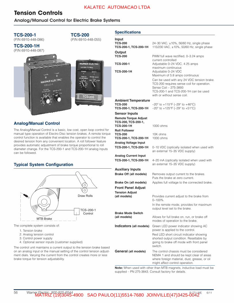
Tension ControlsAnalog/Manual Control for Electric Brake Systems
TCS-200-1(P/N 6910-448-086)
TCS-200-1H(P/N 6910-448-087)
TCS-200(P/N 6910-448-055)
Specifications
InputTCS-200 24–30 VAC, ±10%, 56/60 Hz, single phaseTCS-200-1, TCS-200-1H 115/230 VAC, ±10%, 50/60 Hz, single phase
OutputTCS-200 PWM full wave rectified, 0–3.24 amps
current controlledTCS-200-1 Adjustable 0–24 VDC, 4.25 amps
maximum continuousTCS-200-1H Adjustable 0–24 VDC
Maximum of 5.8 amps continuous
Can be used with any 24 VDC tension brake.TCS-200 requires sense coil for operation.Sense Coil – 275-3893TCS-200-1 and TCS-200-1H can be usedwith or without sense coil.
Ambient TemperatureTCS-200 –20° to +115°F (–29° to +46°C)TCS-200-1, TCS-200-1H –20° to +125°F (–29° to +51°C)
Sensor InputsRemote Torque AdjustTCS-200, TCS-200-1, TCS-200-1H 1000 ohms
Roll FollowerTCS-200 10K ohmsTCS-200-1, TCS-200-1H 1000 ohms
Analog Voltage Input
TCS-200-1, TCS-200-1H 0–10 VDC (optically isolated when used withan external 15–35 VDC supply)
Analog Current Input
TCS-200-1, TCS-200-1H 4–20 mA (optically isolated when used withan external 15–35 VDC supply)
Auxiliary InputsBrake Off (all models) Removes output current to the brakes.
Puts the brake at zero current.
Brake On (all models) Applies full voltage to the connected brake.
Front Panel AdjustTension Adjust (all models) Provides current adjust to the brake from
0–100%.
In the remote mode, provides for maximumoutput level set to the brake.
Brake Mode Switch(all models) Allows for full brake on, run, or brake off
modes of operation to the brake.
Indicators (all models) Green LED power indicator showing ACpower is applied to the control.
Red LED short circuit indicator showingshorted output condition. Resettable bygoing to brake off mode with front panelswitch.
General (all models) The control chassis must be consideredNEMA 1 and should be kept clear of areaswhere foreign material, dust, grease, or oilmight affect control operation.
Note: When used with other than MTB magnets, inductive load must besupplied – PN 275-3843. Consult factory for details.
Analog/Manual ControlThe Analog/Manual Control is a basic, low cost, open loop control formanual type operation of Electro Disc tension brakes. A remote torquecontrol function is available that enables the operator to control thedesired tension from any convenient location. A roll follower featureprovides automatic adjustment of brake torque proportional to rolldiameter change. For the TCS-200-1 and TCS-200-1H analog inputscan be followed.
MTB Brake
Draw Rolls
TCS–200-1Control
Typical System Configuration
The complete system consists of:
1. Tension brake2. Analog tension control3. Control power supply4. Optional sensor inputs (customer supplied)
The control unit maintains a current output to the tension brake basedon an analog input or the manual setting of the control tension adjust-ment dials. Varying the current from the control creates more or lessbrake torque for tension adjustability.
KALATEC AUTOMACAO LTDA
MATRIZ (19)3045-4900 SAO PAULO(11)5514-7680 JOINVILLE(47)3425-0042

P-771-WE 6/11 Warner Electric 800-825-6544 57
Tension ControlsAnalog Control for Electric Brake Systems
MCS-204(P/N 6910-448-017)
(Shown with Housing)
Typical System Configuration
Remote/Analog controlThe MCS-204 control, also completely solid state, is designedfor manual or analog input control. The MCS-204 can controltwo 24 VDC tension brakes in parallel. It also has an antiresid-ual (magnetism) circuit, a brake on and a highly accessible terminal strip for rapid connection. It is designed for use withthe MCS-166 power supply.
MCS-166 Power Supply (page 65).
Specifications
Input 24-28 VDC @ 3 Amps (from MCS-166, 1.5amps for single MCS-166; 3.0 amps fromdual MCS-166’s) or other power source.
Output Pulse with modulated 0-24 VDC for 24 voltWarner Electric tension brakes.
Ambient Temperature –20° to +113°F (–29° to +45°C).
External InputsTorque Adjust Controls tension by applying the desired
amount of current to the brake.
Brake On Applies full current to tension brake.
Brake Off Removes brake current and appliesantiresidual voltage to eliminate brakedrag. Useful when changing rolls.
Operating ModesLocal Torque Adjust Knob on front panel.
Remote Torque Adjust Via remote potentiometer.
Roll Follower Using external potentiometer.
Current Loop 1–5 mA, 4–20 mA, 10–50 mA. VoltageInput: 0–14.5 VDC.
Mounting Available for panel mounting with exposedwiring or wall/shelf mounting with conduitentrance. Must be ordered with eitherwall/shelf or panel enclosures.
Requires enclosure, see page 66.
TB SeriesBrake
Draw Rolls
MCS-204
MCS-166
AnalogSignal
The complete system consists of:
1. Tension brake2. Analog tension control3. Control power supply4. Analog signal input (customer
supplied)
The control unit maintains a current output tothe tension brake based on an analog inputor the manual setting of the control tensionadjustment dials. Varying the current fromthe control creates more or less brake torquefor tension adjustability.
KALATEC AUTOMACAO LTDA
MATRIZ (19)3045-4900 SAO PAULO(11)5514-7680 JOINVILLE(47)3425-0042

58 Warner Electric 800-825-6544 P-771-WE 6/11
Tension ControlsAnalog Control for Electric Brake Systems
TCS-220(P/N 6910-448-027)
(Shown with Housing)
Typical System Configuration
The remote analog input control is anopen loop system designed to alloweasy interface with existing or speciallydesigned customer controls to com-plete a closed loop system. The systemalso offers complete operator controlla-bility for manual tensioning control.
TCS-167 Power Supply, (page 65).
Note: When used with other than MTB mag-nets, a resistor, 68 ohms, 25 watts, must beadded. Consult factory for details.
Specifications
Input TCS-220 – 48 VDC @ 1.6 Amps continuous, 48 VDC @ 6 Ampsintermittent, 1.6% duty cycle, 30 sec. on time, 8–12 VDC @ 1.5Amps.TCS-167 – 120 VAC, 50/60 Hz or 240 VAC, 50/60 Hz (Switchselectable).
Output TCS-220/TCS-167 – 0–270 mA/magnet (running); 270–500mA/magnet (stopping).
Ambient Temperature –20° to +113°F (–29° to +45°C).
External InputsTorque Adjust Controls tension by applying the desired amount of current to
the brake.
Emergengy Stop Applies full current to tension brake.
Brake Off Removes brake current and applies antiresidual current toeliminate brake drag. Useful when changing rolls.
Operating ModesLocal Torque Adjust Knob on front panel.
Remote Torque Adjust Via 1K to 10K ohm potentiometer.
Roll Follower Via 1k to 10k ohm potentiometer.
Current Loop 1–5 mA, 4–20 mA, 10–50 mA current source.
Voltage Input 0–14.5 VDC.
AdjustmentsTorque Adjust/Span Controls output manually in local torque mode. Sets maximum
control span in remote torque adjust, roll follower, current loop; orvoltage input mode.
Zero adjust Potentiometer adjustment for setting zero output level. Front panelaccess.
Brake off input Terminal strip connection which provides for removal of brakecurrent and applies antiresidual current to eliminate brake drag.Used primarily when changing rolls.
Brake on input Terminal strip connection applies full current to brake whenactivated regardless of input control signal. Used for emergencystops.
Mounting TCS-220 – available as panel mounted with exposed wiring, orwall/shelf mounted with conduit entrance.TCS-167 – Available with open frame or wall/shelf mounted enclo-sure with conduit
Requires enclosure, see page 66.
Brake
Draw Rolls
AnalogControl
Signal InputTCS–220Control
TCS–167Power Supply
The complete system consists of:
1. Tension brake2. Analog tension control3. Control power supply4. Analog signal input (customer
supplied)
The control unit maintains a current output tothe tension brake based on an analog inputor the manual setting of the control tensionadjustment dials. Varying the current fromthe control creates more or less brake torquefor tension adjustability.
KALATEC AUTOMACAO LTDA
MATRIZ (19)3045-4900 SAO PAULO(11)5514-7680 JOINVILLE(47)3425-0042

P-771-WE 6/11 Warner Electric 800-825-6544 59
Tension ControlsAnalog Control for Pneumatic Brake Systems
MCS-208(P/N 6910-448-067)
(Shown with Housing)
The MCS-208 control, also completelysolid state, is designed for manual oranalog input control. The MCS-208 fea-tures a highly accessible terminal stripfor rapid connection, and it is designedfor use with the MCS-166 Power Supply.
The remote analog input control isan open loop system designed to alloweasy interface with existing or speciallydesigned customer controls to com-plete a closed loop system. The systemalso offers complete operator controlla-bility for manual tensioning control.
MCS-166 Power Supply, (page 65).
Note: When used with other than MTBmagnets, a 68 ohm, 25 watt resistor must beadded. Consult factory for details.
Specifications
Input Power 24–28 VDC, 0.5 amps maximum (from MCS-166 power supply orother source)
Outputs Switch selectable current or voltage
Voltage: 0–10 VDC
Current: 1–5 mA, 4–20 mA, 10–50 mA
Will operate most electric to pneumatic transducers available.
Ambient Temperature +32° to +120°F (0° to +49°C).
External InputsBrake On Applies maximum output signal (voltage or current) to the
transducer
Brake Off Removes output from the transducer and applies minimum levels
AdjustmentsFront Panel Zero Adjust: Provides for adjustment of minimum input to
correspond to minimum output levels
Torque Adjust/Span: Provides for manual adjust in manual mode,or span adjustment when in other operating modes
Operating Modes Local torque adjustRemote torque adjustRoll followerAnalog voltage inputAnalog current input
Mounting Available with panel mounting with exposed wiring or wall/shelfmounting with conduit entrances. Note: Must be ordered withwall/shelf enclosure or with panel mount enclosure.
Requires enclosure, see page 66.
Typical System Configuration
Brake
Transducer MCS-166PowerSupply
MCS-208Analog Control
Analog ControlInput
The complete system consists of:
1. Pneumatic tension brake2. Analog tension control3. Control power supply4. Analog signal input (customer
supplied)5. E to P transducer
The control unit maintains a current output tothe tension brake based on an analog inputor the manual setting of the control tensionadjustment dials. Varying the current fromthe control creates more or less brake torquefor tension adjustability.
KALATEC AUTOMACAO LTDA
MATRIZ (19)3045-4900 SAO PAULO(11)5514-7680 JOINVILLE(47)3425-0042

60 Warner Electric 800-825-6544 P-771-WE 6/11
Tension ControlsAnalog Splicer Control for Electric Brake Systems
TCS-320(P/N 6910-448-043)
The analog splicer control providesdual brake functions with manual oper-ator or analog input control requiringsimultaneous brake tensioning andholding.
The system also offers completeoperator controllability for manual ten-sioning control.
TCS-168 Power Supply, (page 65).
Note: When used with other than MTB mag-nets, a 68 ohm, 25 watt resistor must beadded. Consult factory for details.
Specifications
Input TCS-320 – 48 VDC @ 3.2 Amps continuous, 48 VDC @ 12 Ampsintermittent, 1.6% duty cycle, 30 sec. on time, 8–12 VDC @ 3.0Amps.
TCS-168 – 120 VAC, 50/60 Hz or 240 VAC, 50/60 Hz (Switch selectable).
Output TCS-320/TCS-168 – 0–270 mA/magnet (running); 270–500 mA/mag-net (stopping) on controlled output channel, 0 to 90 mA/magnet(typ.) on holding output channel.
Ambient Temperature –20° to +113°F (–29° to +45°C).
External InputsTorque Adjust Controls tension by applying the desired amount of torque to the
brake.
Brake On Applies full current to tension brake.
Brake Off Removes brake current and applies antiresidual current to eliminatebrake drag. Useful when changing rolls.
Operating ModesLocal Torque Adjust Knob on front panel.
Remote Torque Adjust Via 1K to 10K ohm potentiometer.
Roll Follower Via 1k to 10k ohm potentiometer.
Current Loop 1–5 mA, 4–20 mA, 10–50 mA current source.
Voltage Input 0–14.5 V DC.
AdjustmentsTorque Adjust/Span Controls output manually in local torque mode. Sets maximum
control span in remote torque adjust, roll follower, current loop, orvoltage input mode.
Zero adjust Potentiometer adjustment for setting zero output level. Front panelaccess.
Brake off input Terminal strip connection which provides for removal of brakecurrent and applies antiresidual current to eliminate brake drag.
Brake on input Terminal strip connection applies full current to brake when activatedregardless of input control signal. Used for emergency stops.
Mounting TCS-168 – available with open frame or wall/shelf mountedenclosure with conduit entrance.
TCS-320 – available as open frame or a NEMA 4 enclosure withremote control station.
Brake
Brake
Draw Rolls
TCS–320Control
TCS–168PowerSupplyAnalog Signal
The complete system consists of:
1. Two tension brakes2. Analog splicer control3. Control power supply4. Analog signal input (customer
supplied)
The control unit maintains a current output tothe tension brake based on an analog inputor the manual setting of the control tension
adjustment dials. Varying the current fromthe control creates more or less brake torquefor tension adjustability.
The TCS-320 can function as a splicercontrol or a dual brake control. With the useof the jumper board (included), the TCS-320can control up to 24 magnets.
Typical System Configuration
KALATEC AUTOMACAO LTDA
MATRIZ (19)3045-4900 SAO PAULO(11)5514-7680 JOINVILLE(47)3425-0042

P-771-WE 6/11 Warner Electric 800-825-6544 61
Tension ControlsDancer Control for Electric Brake Systems
MCS-203(P/N 6910-448-014)
(Shown with Housing)
Typical System Configuration
The completely solid state MCS-203Dancer Control Module is designed forautomatic web tensioning through theuse of a dancer roll. The MCS-203 cancontrol two 24 VDC tension brakes inparallel. It works on the concept of aP-I-D controller and has internal P, I & Dadjustments for optimum performanceregardless of brake size.
MCS-166 Power Supply, (page 65).
Specifications
Input 24–28 VDC @ 3 Amps (from MCS-166, 1.5 amps for singleMCS-166; 3.0 amps from dual MCS-166’s) or other power source.
Output Pulse width modulated 0–24 VDC for 24 volt Warner Electrictension brakes.
Ambient Temperature –20° to +113°F (–29° to +45°C).
External InputsDancer Potentiometer Provides the feedback signal of dancer position and movement
for input to the control.
Brake On Applies full current to tension brake.
Brake Off Removes brake current and applies antiresidual current toeliminate brake drag. Useful when changing rolls.
Antidrift Input Nullifies integrator portion of control for faster brake response.Important for splicing and mid-roll starting.
Mounting Available for panel mounting with exposed wiring or wall/shelfmounting with conduit entrance. Must be ordered with eitherwall/shelf or panel enclosures.
Requires enclosure, see page 66.
Brake
Sensor
Dancer RollMCS–203Control
MCS–166PowerSupply
The complete system consists of:
1. Tension brake2. Dancer tension control3. Control power supply4. Pivot point sensor5. Dancer roll assembly (customer
supplied)
The control unit maintains a current output tothe tension brake based on an analog inputor the manual setting of the control tensionadjustment dials. Varying the current fromthe control creates more or less brake torquefor tension adjustability.
KALATEC AUTOMACAO LTDA
MATRIZ (19)3045-4900 SAO PAULO(11)5514-7680 JOINVILLE(47)3425-0042

62 Warner Electric 800-825-6544 P-771-WE 6/11
Tension ControlsDancer Control for Electric Brake Systems
TCS-210(P/N 6910-448-026)
(Shown with Housing)
Typical System Configuration
This closed loop tension control systemautomatically controls tension onunwinding materials such as paper,film, foil, cloth and wire.
TCS-167 Power Supply, (page 65).
Note: When used with other than MTB mag-nets, a 68 ohm, 25 watt resistor must beadded. Consult factory for details.
Specifications
Input TCS-210 – 48 VDC @ 1.6 Amps continuous, 48 VDC @ 6 Ampsintermittent, 1.6% duty cycle, 30 sec. on time, 8–12 VDC @ 1.5Amps.
TCS-167 – 120 VAC, 50/60 Hz or 240 VAC, 50/60 Hz (Switchselectable).
Output TCS-210/TCS-167 – 0–270 mA/magnet (running); 270–500mA/magnet (stopping).
Ambient Temperature –20° to +113°F (–29° to +45°C).
External InputsDancer Potentiometer Provides the feedback signal of dancer position and movement
for input to the control.
Brake On Applies holding brake voltage.
Anti-Drift Input Nullifies integrator portion of control for faster brake response.Important at startup and for mid-roll starts.
Brake Off Removes brake current and applies antiresidual current toeliminate brake drag. Useful when changing rolls.
Mounting TCS-210 – available as panel mounted with exposed wiring, orwall/shelf mounted with conduit entrance.
TCS-167 – available with open frame or wall/shelf mountedenclosure with conduit entrance.
Requires enclosure, see page 66.
Brake
Sensor
Dancer RollTCS–210Control
TCS–167PowerSupply
The complete system consists of five components:
1. Tension brake2. Dancer tension control3. Control power supply4. Pivot point sensor5. Dancer roll assembly (customer
supplied)
The weight of the dancer roll or loading onthe dancer determines the tension on theweb and the remainder of the system oper-ates to hold the dancer roll as steady aspossible. When the dancer positionchanges, the Warner Electric pivot pointsensor tracks the direction and speed of thechange and sends an electric signal to theclosed loop control, which, in turn, relays acorrective signal to the Electro Disc tensionbrake. Increasing current to the Electro Disc
increases braking torque to elevate thedancer to the desired position, while reduc-ing brake current lowers the dancer.
The closed loop dancer control system iscompletely automatic, limiting the need foroperator involvement and the potential forinaccurate tension control. The system offersexceedingly rapid response that, in effect,corrects tension errors before they reach thework area of the processing machine.
KALATEC AUTOMACAO LTDA
MATRIZ (19)3045-4900 SAO PAULO(11)5514-7680 JOINVILLE(47)3425-0042

P-771-WE 6/11 Warner Electric 800-825-6544 63
Tension ControlsDancer Control for Pneumatic Brake Systems
MCS-207(P/N 6910-448-066)
(Shown with Housing)
The dancer control, MCS-207 isdesigned for automatic web tensioningthrough the use of a dancer roll.TheMCS-207 can control either a voltage topneumatic or current to pneumatictransducer with an air operated clutchor brake. It works on the concept of aP-I-D controller and has internal adjust-ments of the P-I-D loops for optimumperformance regardless of the brakesize.
MCS-166 Power Supply, (page 65).
Note: When used with other than MTB mag-nets, a 68 ohm, 25 watt resistor must beadded. Consult factory for details.
Specifications
Input 24–28 VDC, 0.5 amps maximum (from MCS-166 or other powersource)
Output Switch selectable current or voltage
Voltage: 0–10 VDC
Current: 1–5 mA, 4–20mA, 10–50mA
Will operate most electric to pneumatic transducers available.
Ambient Temperature +32° to +120°F (0° to +49°C).
Control Input Pivot point sensor, MCS-605-1 or TCS-605-5
External InputsBrake On Applies maximum output signal (voltage or current) to the
transducer
Brake Off Removes output from the transducer and applies minimum level
Anti-Drift Provides integrator reset function for mid-roll starting
AdjustmentsFront Panel Dancer Position: sets dancer operating position
Gain: Controls overall system response based on change ofdancer input signal
Mounting Available as panel mounted with exposed wiring, or wall/shelfmounted with conduit entrance. Note: Must be ordered withwall/shelf enclosure or with panel mount enclosure.
Requires enclosure, see page 66.
Typical System Configuration
Brake
Sensor
Transducer MCS-166PowerSupply
MCS-207Control
The complete system consists of:
1. Pneumatic tension brake2. Dancer tension control3. Control power supply4. Pivot point sensor5. E to P transducer6. Dancer roll assembly (customer
supplied)
The control unit maintains an output to thetension brake based on an analog input orthe manual setting of the control tensionadjustment dials. Varying the signal fromthe control creates more or less braketorque for tension adjustability.
KALATEC AUTOMACAO LTDA
MATRIZ (19)3045-4900 SAO PAULO(11)5514-7680 JOINVILLE(47)3425-0042

64 Warner Electric 800-825-6544 P-771-WE 6/11
Tension ControlsDancer Splicer Control for Electric Brake Systems
Brake
Sensor
Dancer RollTCS–310Control
TCS–168PowerSupply
Brake
The complete system consists of five components:
1. Two tension brakes2. Dancer splicer control3. Control power supply4. Pivot point sensor5. Dancer roll assembly (customer
supplied)
The weight of the dancer roll or loading onthe dancer determines the tension on theweb and the remainder of the system oper-ates to hold the dancer roll as steady aspossible. When the dancer positionchanges, the Warner Electric pivot pointsensor tracks the direction and speed of thechange and sends an electric signal to theclosed loop control, which, in turn, relays acorrective signal to the Electro Disc tensionbrake. Increasing current to the Electro Disc
increases braking torque to elevate thedancer to the desired position, while reduc-ing brake current lowers the dancer.
The closed loop dancer control system iscompletely automatic, limiting the need foroperator involvement and the potential forinaccurate tension control. The system offersexceedingly rapid response that, in effect,corrects tension errors before they reach thework area of the processing machine.
TCS-310(P/N 6910-448-042)
This closed loop tension control systemautomatically controls tension onunwinding materials such as paper,film, foil, cloth and wire.
TCS-168 Power Supply, (page 65).
Note: When used with other than MTBmagnets, a 68 ohm, 25 watt resistor must beadded. Consult factory for details.
Specifications
Input TCS-310 – 48 VDC @ 3.2 Amps continuous, 48 VDC @ 12 Ampsintermittent, 1.6% duty cycle, 30 sec. on time, 8–12 VDC @ 3.0Amps.
TCS-168 – 120 VAC, 50/60 Hz or 240 VAC, 50/60 Hz (Switchselectable).
Output TCS-310/TCS-168 – 0–270 mA/magnet (running); 270–500 mA/magnet (stopping) on controlled output channel 0 to 90 mA holding channel.
Ambient Temperature –20° to +113°F (–29° to +45°C).
External InputsDancer Potentiometer Provides the feedback signal of dancer position and movement
for input to the control.
Brake On Applies holding brake voltage.
Anti-Drift Input Nullifies integrator portion of control for faster brake response.Important for start-ups.
Brake Off Removes brake current and applies antiresidual current toeliminate brake drag. Useful when changing rolls.
Mounting TCS-310 – available as open frame or as NEMA 4 enclosure withremote control station.
TCS-168 – available with open frame or wall/shelf mounted enclo-sure with conduit entrance.
Typical System Configuration
KALATEC AUTOMACAO LTDA
MATRIZ (19)3045-4900 SAO PAULO(11)5514-7680 JOINVILLE(47)3425-0042

P-771-WE 6/11 Warner Electric 800-825-6544 65
The TCS-167 power supply is designedto provide the correct power input toMCS-207, TCS-210, and TCS-220 ten-sion controls. Its switch selectable inputallows the user to adapt to 120 or 240VAC. It has dual voltage circuits to pro-vide low voltage power and anti-resid-ual output as well as power to operatea brake. The TCS-167 is available withan enclosure or open frame for controlpanel mounting.
Specifications
Input120 VAC or 220/240 VAC, ± 10%, 50/60 Hz,1 phase. (switch selectable)
OutputUnregulated 9-12 VDC @ 1.5 Amps
Unregulated 48 VDC @ 1.6 Ampscontinuous, 48 VDC @ 6 Amps intermittent,1.6% duty cycle, 30 seconds on time.
Ambient Temperature-20°F. to +113°F. (-29°C. to +45°C.)
MountingOpen frame or enclosed wall/shelf mountwith conduit entrance
The TCS-168 power supply is designedto provide the correct power input tothe TCS-310 Dancer Splicer Controland the TCS-320 Analog SplicerControl. Its switch selectable inputallows the user to adapt to 120 or 240VAC. It has dual voltage circuits to pro-vide low voltage power and anti-resid-ual output as well as power to operatetwo brakes. The TCS-168 is availablewith an enclosure or open frame forcontrol panel mounting.
Specifications
Input120 VAC or 220/240 VAC, +_ 10%, 50/60 Hz,1 phase. (switch selectable)
OutputUnregulated 9-12 VDC @ 3 Amps
Unregulated 48 VDC @ 3.2 Ampscontinuous, 48 VDC @ 6 Amps intermittent,1.6% duty cycle, 30 seconds on time.
Ambient Temperature-20°F. to +113°F. (-29°C. to +45°C.)
MountingOpen frame or enclosed wall/shelf mountwith conduit entrance
Tension ControlsPower Supplies and Accessories
MCS-166(P/N 6910-448-013)
(Shown with Housing)
TCS-167(P/N 6910-448-025)
TCS-168(P/N 6910-448-032)
Magnet Selector Stat ic SwitchThe magnet selector switch allowsmagnets to be dynamically or staticallyadded or removed from the tensionsystem to be tailored to the ap pli ca tionneed. Examples include shedding mag-nets for narrow, light webs near core oradding magnets for emergency stops.
Each selector switch provides two cir-cuits, each capable of switching up tofour magnets.
How to OrderTo order, specify Magnet Selector StaticSwitch 6910-101-007.
5.65max
6-32 Phillips Head Screws4 places. Cover
5.05max
p
2.58max
Power Supply forMCS-203, MCS-204, MCS-207,and MCS-208 ControlsWarner Electric’s MCS-166 is the com-panion power supply module to beused with MCS-203 and MCS-204 ten-sion controls. The MCS-166 suppliesthe 24–28 VDC that these systemsrequire. The MCS-166 is a modular unitdesigned to couple with its respectivecontrol or it can be mounted separately.It is also fused for overload protection,has a voltage indicator light, and isinternally protected against 240 VACinput when set for 120 VAC.
Specifications
Input120 VAC 50/60 Hz or 240 VAC 50/60 Hz(switch selectable).Output24–28 VDC (1.5 Amps).
Note: For dual brake application, twoMCS-166’s are required, 3.0 amps output.
Ambient Temperature–20° to +113°F (–29° to +45°C).
MountingAvailable for panel mounting with exposedwiring or wall/shelf mounting with conduitentrance. Must be ordered with eitherwall/shelf or panel enclosures. Requires enclosure, see page 66.
KALATEC AUTOMACAO LTDA
MATRIZ (19)3045-4900 SAO PAULO(11)5514-7680 JOINVILLE(47)3425-0042

66 Warner Electric 800-825-6544 P-771-WE 6/11
Tension ControlsDimensions/Enclosures
4.00
1.00
3.00
0.12
0.645
3.00
0.812
1.0
0.751.50
3.007.82 Max6.59 Max1.23
Bracket base may bemounted either way as shownfor shelf mount, or removed entirely forwall mount.
Front/bracket may bemounted either way as shown
5.60 Max
0.62
6.00
7.256.50
0.503.502.50
3.250.17 10-32 x 5/8 (4) Studs
0.37
6.83 Max
Panel Mount
Tension Controls – For use with MCS-203, MCS-204, MCS-207 or MCS-208 orderpart number 6910-448-015.For use with TCS-210 or 220, order part number 6910-448-028.
Power Supplies – For use with MCS-166, order part number 6910-448-018.
Ribbon Cable
A ribbon cable has been added to the rear terminal board of the MCS-203/204/207/208 and MCS-166 enclosures to improve performance and reliability. The upgrade is fully retrofitable and enclosure part numbers have not changed.
Wall/Shelf MountTension Controls – For use with MCS-203, MCS-204, MCS-207 or MCS-208 order
part number 6910-448-016.For use with TCS-210 or 220, order part number 6910-448-029.
Power Supplies – For use with MCS-166, order part number 6910-448-019.
.875 DIA. 2 PLCS.
2.87
1.253.00
6.00
7.50
TCS-200-1
POWER SHORT
TENSIONADJUSTMENT BRAKE MODE
.31 Dia.
®
Dimensions
TCS-200-1
KALATEC AUTOMACAO LTDA
MATRIZ (19)3045-4900 SAO PAULO(11)5514-7680 JOINVILLE(47)3425-0042

P-771-WE 6/11 Warner Electric 800-825-6544 67
Tension ControlsDimensions/Enclosures
Dual Brake Controls
TCS-310, TCS-320
Power SuppliesTCS-167, TCS-168
8-1/8(8.125)
9/16(0.5625)7/16
(0.4375)7-5/8
(7.625)
3 Holes 9/32 Dia.
4-1/4 (4.250)
11/16(0.6875)
7-5/8(7.625)
2 Holes
11/16(0.6875)
9-5/8(9.625)
15/32(0.46875)
2 Slots
9/16 (0.5625)
8-1/2(8.5))
5/16 Dia. Holes(4 Places) 3/8
12-3/4
11
1210
1213-1/2
10-1/810-3/4
5/16
10-7/8
10-3/8
1/413/64 Dia. Holes (4 Places)
6 1/8
4-1/2
(P/N 6910-448-033)
KALATEC AUTOMACAO LTDA
MATRIZ (19)3045-4900 SAO PAULO(11)5514-7680 JOINVILLE(47)3425-0042