Embed Size (px)
Citation preview

Shell Exploration & Production
GEOLOGISTS AND RESERVOIR ENGINEERS
SHOULD BE FRIENDS!!!!
Kachi Onyeagoro, Frans Van der Vlugt, Steve Naruk, Mark Barton & Steve Jolley

Shell Exploration & Production
STRATIGRAPHY AND SIMULATION
STRUCTURAL AND SIMULATION
INTRODUCTION
STRUCTURAL, STRATIGRAPHY AND SIMULATION

Shell Exploration & Production
Well 4
Low NTG Upper Sand (27%)
Well 5
Well 5
Well 4
High NTG Upper Sand (76%)GEOLOGISTS ARE ALWAYS HAPPY!!!
NO HISTORY MATCH!!
Well 5
INTRODUCTION
CAN’T GET A HISTORY MATCH!!

Shell Exploration & Production
RESERVOIR ENGINEERS WHEN HAPPY!!!!Case 2: Fault Tr =0, t = 14 yr
Case 1: Fault Tr =1, t = 14 yr
RESERVOIR ENGINEERS WHEN UNHAPPY!!!!
THEY GET A HISTORY MATCH!! Or PREDICT….
INTRODUCTION
Shell Exploration & Production
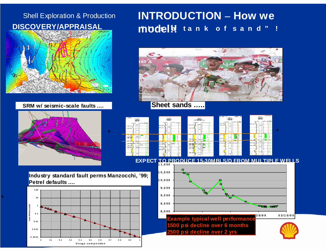
SRM w/ seismic-scale faults …. Sheet sands …..
+ +
+
Industry standard fault perms Manzocchi, ’99; Petrel defaults ….
0 . 00 01
0 .0 01
0. 01
0 .1
1
10
1 00
0 0.1 0 .2 0 .3 0 .4 0 .5 0 .6 0 .7 0 .8 0 .9 1
G o ug e c o m p o s itio n
Faul
t Rx P
erm
(mD)
8 , 0 0 0
8 , 5 0 0
9 , 0 0 0
9 , 5 0 0
1 0 , 0 0 0
1 0 , 5 0 0
1 1 , 0 0 0
0 1 / 0 5 / 9 8 0 7 / 2 4 / 9 8 0 2 / 0 9 / 9 9 0 8 / 2 8 / 9 9 0 3 / 1 5 / 0 0Example typical well performance1500 psi decline over 6 months2500 psi decline over 2 yrs
EXPECT TO PRODUCE 15-30MBLS/D FROM MULTIPLE WELLS
“ I t ’ s a t a n k o f s a n d ” !DISCOVERY/APPRAISALINTRODUCTION – How we model!!

Shell Exploration & Production
It’s the stratigraphy…
It’s the fault rock properties…. It’s differential
depletion and compaction…
0
1000
2000
3000
4000
5000
6000
7000
8000
9000
10000
11000
J-00
J-00
M-00
A -00
M-00
J-00
J-00
A-00
S -00
O-00
N-00
D-00
J-01
J-01
M-01
A-01
M-01
J-01
J-01
A-01
S-01
O-01
N-01
D-01
J-02
F-02
M-02
A-02
M-02
J-02
J-02
A-02
S-02
O-02
N-02
D-02
J-03
F-03
M-03
A-03
M-03
J-03
J-03
A -03
FTPr
essu
re (p
sig)
Field Performance Issues…INTRODUCTION
Why Did We Fail?…

Shell Exploration & Production STRUCTURAL MODELING NIGHTMARES DO HAPPEN!!
Shell Exploration & Production
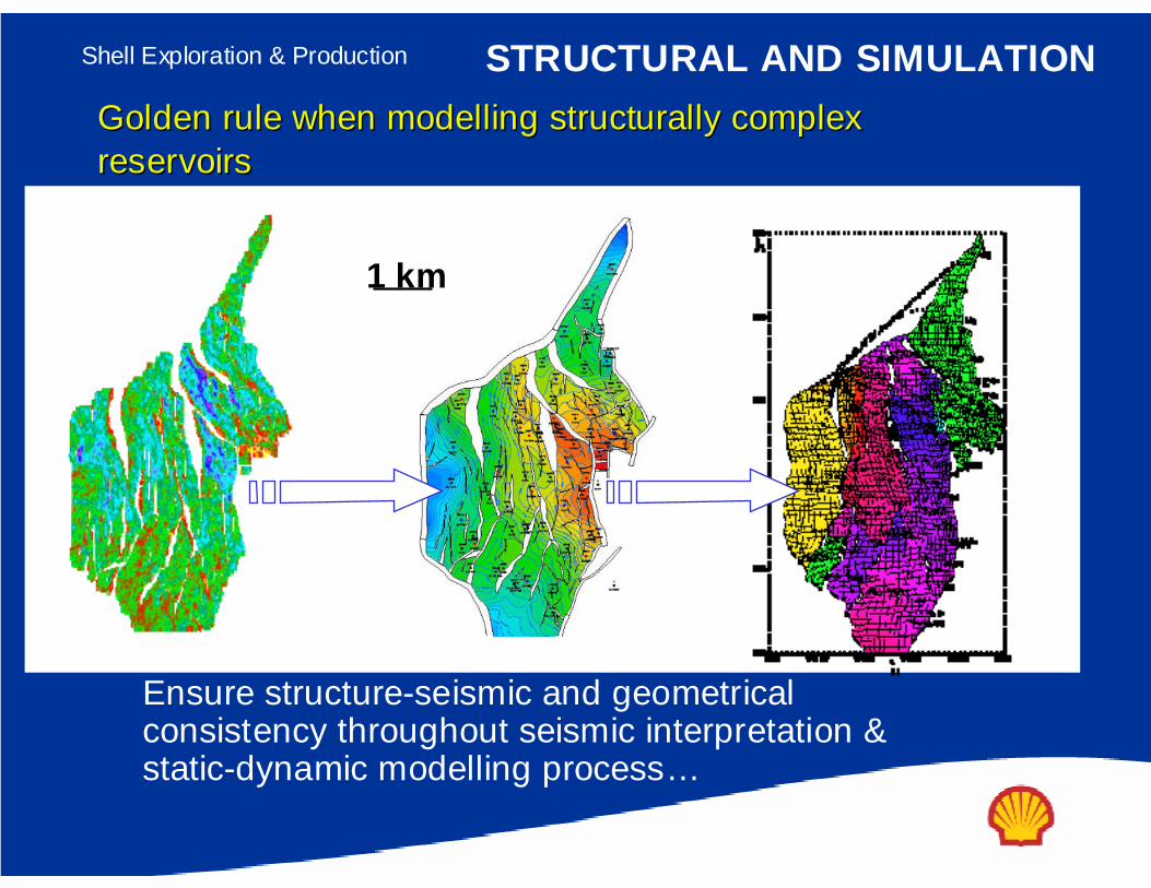
1 km
Golden rule when Golden rule when modellingmodelling structurally complex structurally complex reservoirsreservoirs
Ensure structure-seismic and geometrical consistency throughout seismic interpretation & static-dynamic modelling process…
STRUCTURAL AND SIMULATION

Shell Exploration & Production
Build fault model with structurally validated geometries (seismic display in FAPS, but cross-reference to Seisworks also direct link via Openworks). Import to TrapTester, QC and Edit Horizon-Fault Intersection
STRUCTURAL AND SIMULATION

Shell Exploration & Production
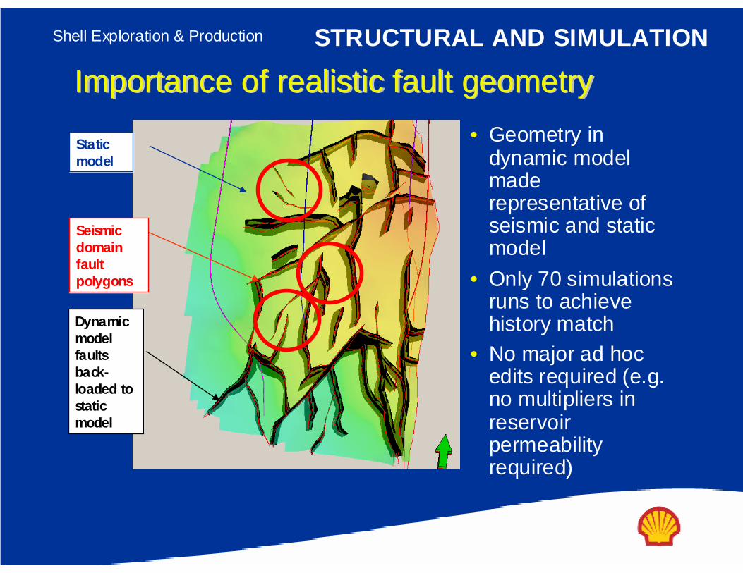
Dynamic model faults back-loaded to Static model
Seismic domain fault polygons
Static model
Importance of realistic fault geometryImportance of realistic fault geometry
• Geometry in dynamic model is a poor representation of seismic and static model
• Over 225 simulations runs –no history match
– Huge number of ad hoc edits
–Even tried increasing permeability of layers increasing by 5 fold
STRUCTURAL AND SIMULATION
Shell Exploration & Production
Seismic domain fault polygons
Dynamic model faults back-loaded to static model
Static model
Importance of realistic fault geometryImportance of realistic fault geometry• Geometry in
dynamic model made representative of seismic and static model
• Only 70 simulations runs to achieve history match
• No major ad hoc edits required (e.g. no multipliers in reservoir permeability required)
STRUCTURAL AND SIMULATION

Shell Exploration & Production
Importance of realistic fault propertiesImportance of realistic fault properties
• TMs calculated based on realistic fault properties (permeability and thickness)
• Note that large variation in TM along fault plane
• Variation in TMsrealistic unlike when single TM per fault is used
STRUCTURAL AND SIMULATION

Shell Exploration & Production
Faults in BHI logs
Example “subtle faults” in horizontal well
Subtle faultsSmallest resolvable fault block ≈ 10 acres
Detailed structural, BHI and attribute analyses shows, additional, “subtle” faults
Faults in BHI logs
Example “subtle faults” in horizontal well
Faults in BHI logs
Example “subtle faults” in horizontal well
Subtle faultsSmallest resolvable fault block ≈ 10 acres
Subtle faultsSmallest resolvable fault block ≈ 10 acres
Detailed structural, BHI and attribute analyses shows, additional, “subtle” faults
STRUCTURAL AND SIMULATION

Shell Exploration & Production
Capillary entry pressure modeling
I m p o r t a n c e o f c o n s i d e r i n g m u l t iI m p o r t a n c e o f c o n s i d e r i n g m u l t i -- p h a s e f l o wp h a s e f l o w
• A b o v e p e t r o l e u m w a t e r c o n t a c t t w o o r m o r e p h a s e s m a y b e p r e s e n t i n p o r e s p a c e
• I m p o r t a n t t o t a k e i n t o a c c o u n t r e l a t i v e p e r m e a b i l i t y , w h i c h v a r i e s a s a f u n c t i o n o f p h a s e s a t u r a t i o n ( i . e . h e i g h t a b o v e f r e e w a t e r l e v e l )
cross-
fault fl
ow
no cro
ss-fau
lt flow
top reservoir
Petroleum saturation in fault zone
Height
above
free-w
ater le
vel
1 0
1
1
1
1
2
Petroleum saturation in fault zone
Relativ
e perm
eability
1 0
1
3
4
1
0
1
1
1 & 2
4
3
krwkrp
3
1
1
4
3
2
AT THIS POINT, WE HAVE BEATEN THE STRUCTURAL & FAULT ISSUES TO DEATH!!!!!!
STRUCTURAL AND SIMULATION

Shell Exploration & Production
PETREL TRADITIONAL CHANNEL MODEL,CHANNELS NOT STACKED IN GEOLOGIC ORDER
ENSURE PETREL CHANNELS ARE STACKED IN GEOLOGIC ORDER
STRATIGRAPHY AND SIMULATION

Shell Exploration & Production STRATIGRAPHY AND SIMULATION
Sheet/Shoreface sandsUse Available data toDistribute the shales

Shell Exploration & ProductionCo
pyrig
ht 20
01
SIEP
B.V
.
M e a n d er b e l t X s ect io n @ w e l l
Sh o w in g m ea n d er b e l t a n d e r o d e d h o le s
M eander Be lt Bas e D rape
Channel Base Drape
I nterbed shales
STRATIGRAPHY AND SIMULATIONChannel sands
Use Available data toDistribute the shales

Shell Exploration & Production
Channel base drape (b lue)
Channel base d is c onform i ty (red)
Channel base d is c onform i ty(red s urfac e)
Channel base d is c onform i ty (red)
Channel base drape (b lue)
Channel base drape (b lue)
Conv ergent c hannel m arg in
Channel base lag (orang e)
Channel base lag (orang e)
Core – Log calibration
Image log and core work flow for interpreting sub-seismicreservoir architecture
Copy
right
2001
SI
EP B
.V.
M a tch 9 0_9 0 _2 ca se, M a tch BU
1E-3 0.01 0. 1 1 10 100 1000 1000010
100
1000
Log-Log plot: dp and dp' [psi ] vs dt [hr]
Sk in -0.32 --
Pi 13731.3 psia
k.h 9730 md .ft
k 139 md
S - No Flow 278 ft
E - No Flow 285 ft
N - No Flow 99.2 ft
P.T ANALYSIS
STRATIGRAPHY AND SIMULATION
Europa “L ” Sa nd: MD GC S tar D iagra mGEOCHEMICAL FINGERPRINTING
KKh
SkinBoundaries

Shell Exploration & Production
3rd Order2nd Order1st OrderChannel / Inter-channel
ArchitectureChannel Base Drapes
Channel Margin
Mud Filled Channels
Intra-channel Shales
Infill Architecture
Focus on the Shale Architecture
Ways to Study and Mitigate - Stratigraphy
3rd Order2nd Order1st OrderChannel / Inter-channel
ArchitectureChannel Base Drapes
Channel Margin
Mud Filled Channels
Intra-channel Shales
Infill Architecture
Focus on the Shale Architecture
Ways to Study and Mitigate - StratigraphySTRATIGRAPHY AND SIMULATION

Shell Exploration & ProductionC
opyr
igh
t 20
01
SIE
P B
.V.
Cop
yrig
ht 2
003
S
IEP
B.V
.
Turbidite s tra tigra phic archi te cture - 1s t orde r corre lation a ppe ars laye r cak eDeta ils from c ore, d ip m eter, se ism ic indica te chan ne ls and shale dra pes
N O R TH
SO U T H
A- 3
A- 1 ST
A- 2ST 1 93 5- 1 BP1
9 35 - 1ST 1
93 5- 2
9 34 -1
A- 2O H
U n it A
Sheet (pond ed)
U n it B
Sheet (pond ed)
U n it C
Sheet (pond ed)
U nit D
C hannel (hea led)
STRATIGRAPHY AND SIMULATION

Shell Exploration & Production
Why Stra tigraphic Com partm enta liza tion - c hannel & Res ervoir perform ance be haviour
Reservoir sw eepReduced recovery
Dead ends, pockets of oil only connected via one path to p roducers/ energy source, bypa ssingM ore edges of reservoir, interaction with g ravity
Different W ater/ G as breakthroughFluid mixing, different flooding speeds through different paths
Reservoir pressureLonger/ shorter path -> reservoir pressure d istribution change
De a d e nd s, p oc k et s of oi l on ly c on ne c ted v ia on e pa th to p ro du c er
(Sha le D ra p es )
F lu id m ix in g, d iffe re nt flo od in g s pe e ds throu gh di ffe re n t p ath s
(D eg ree of Am a lg a ma tion )
Ed ge s o f re s erv oi r, inte rac tion w ith g ra v ity (S inu os i ty)
C B D ra pe
STRATIGRAPHY AND SIMULATION

Shell Exploration & Production
Copy
right
2001
SI
EP B
.V.
Copy
right
200
3 SI
EP B
.V.
C om b in ed struc tu ral a nd strat features to gethe r a cco un t for pe rfo rm anc e
S RM w / su btle fau lts … .Amalg am ated Ch ann els + Sh eets … ..
+ +
Actual Bh p’s
+
Sh eet (p on ded )Sh eet (p on ded )
Ama l. ch a n ne lsAma l. ch a n ne ls
Sim u lated Bh p ’s⇒New fault p erm s fu n ctio n … .
⇒
Y ield s ~ HM in m ultip le w ells from “1st
p rin cip les”
0.00 01
0 .0 01
0.01
0.1
1
10
0 001 0 01 0 1 1
Faul
t Rx
Perm
(mD)
lo gK f= f( K h ,Go u g e co mp )
Man zo cc hi 9 9
STRUCTURAL, STRATIGRAPHY AND SIMULATION


![Predicting Fick- and Maxwell-Stefan di usivities in liquids · 2012-08-13 · Predicting Fick- and Maxwell-Stefan di usivities in liquids Thijs J.H. Vlugt [2] (Empirical) Fick formulation](https://img.dokumen.tips/doc/110x75/5f7bdb3d92b88257c561c53c/predicting-fick-and-maxwell-stefan-di-usivities-in-liquids-2012-08-13-predicting.jpg)


![Predicting Fick- and Maxwell-Stefan di usivities in · PDF filePredicting Fick- and Maxwell-Stefan di usivities in liquids Thijs J.H. Vlugt [12] Ternary system of WCA particles that](https://img.dokumen.tips/doc/110x75/5a90259f7f8b9a7f398de9d2/predicting-fick-and-maxwell-stefan-di-usivities-in-fick-and-maxwell-stefan-di.jpg)


