Embed Size (px)
Citation preview

Datasheet50 mm Multicolor RGB Devices (Indicator, Touch Button, Push Button, Optical Sensor, and Beacon)This datasheet contains limited information on K50 Pro Devices with PICK-IQ™. For complete information on configuration,performance, troubleshooting, dimensions, and accessories, please refer to the PICK-IQ™ Devices Instruction Manual. Go to www.bannerengineering.com and search 206185 to view the PICK-IQ™ Devices Instruction Manual or 209995 to view the DeviceRegister Map. Use of this document assumes familiarity with pertinent industry standards and practices.
• PICK-IQ gives full access to color, flashing, rotating, and dimming settings as well as advanced animations such asdynamic sequence mode and LED control
• Output settings, including on and off delays, output function, and output state are also available with PICK-IQ• PICK-IQ brings faster response speed and simplified programming to Modbus RTU communication
Indicator
Optical Sensor
Touch Button
Push Button
Beacon
WARNING:• Do not use this device for personnel protection• Using this device for personnel protection could result in serious injury or death.• This device does not include the self-checking redundant circuitry necessary to allow its use in
personnel safety applications. A device failure or malfunction can cause either an energized (on) or de-energized (off) output condition.
Models
Touch Button Models
• Excellent immunity to false triggering by water spray, oils, and other foreign materials• Rated IEC IP67 and IP69K per DIN 40050-9• Can be actuated with bare hands or gloves; adjustable sensitivity
FamilyK50
P = Pro Q = 4-pin integral M12/Euro-style quick disconnect Q2PS = Dual 240 mm (9.45 in) PVC shielded cables with 5-pin integral M12/Euro-style quick disconnects
Q2PSConnector
Models with a quick disconnect require a mating cordset
ActivationMethod
T = Touch
Housing
Blank = Standard Dome
Control
S = Serial/PICK-IQ™
P T SStyle
K50 Pro Devices with PICK-IQ™
Original Document212906 Rev. C
1 February 2021
212906

Push Button and Optical Sensor Models
• Optical sensor models are immune to ambient light, EMI and RFI interference• Optical sensor models rated IEC IP67 and IP69K per DIN 40050-9• Push Button models rated IEC IP65
FamilyK50
P = Pro Q = 4-pin integral M12/Euro-style quick disconnect Q2PS = Dual 240 mm (9.45 in) PVC shielded cables with 5-pin integral M12/Euro-style quick disconnects
QConnector
Models with a quick disconnect require a mating cordset *Cutoff distance will vary from specified range based on target and tolerances
ActivationMethod
FF50 = 50 mm Fixed Field*FF100 = 100 mm Fixed Field*
Control
S = Serial/PICK-IQ™
P FF50 SStyle
FF200 = 200 mm Fixed Field*PB = Push Button
Indicator Models
• Bright, uniform indicator light• Rated IEC IP67 and IP69K per DIN 40050-9
FamilyK50
P = Pro Q = 4-pin integral M12/Euro-style quick disconnect Q2PS = Dual 240 mm (9.45 in) PVC shielded cables with
QP = 150 mm (6 in) PVC cable with 4-pin integral M12/ 5-pin integral M12/Euro-style quick disconnects
Euro-style quick disconnects
Q2PSConnector
Models with a quick disconnect require a mating cordset
Housing
L = DomeBL = Beacon
Control
S = Serial/PICK-IQ™
P L SStyle
WiringCompatible cordsets can be found in the PICK-IQ™ Devices Instruction Manual (206185).
Wiring for the Q Models
4-pin M12/Euro-style Male 4-pin M12/Euro-style Female Pin Wire Color Connection
1
43
22
34
1
1 brown 10 V DC to 30 V DC
3 blue DC common
4 black RS-485 (-)
2 white RS-485 (+)
Wiring for the Q2PS Models
5-pin M12/Euro-style Male 5-pin M12/Euro-style Female Pin Wire Color Connection
1
453
22
34
1
5
1 brown 10 V DC to 30 V DC
3 blue DC common
4 black RS-485 (-)
2 white RS-485 (+)
5 gray Shield
K50 Pro Devices with PICK-IQ™
2 www.bannerengineering.com - Tel: + 1 888 373 6767 P/N 212906 Rev. C
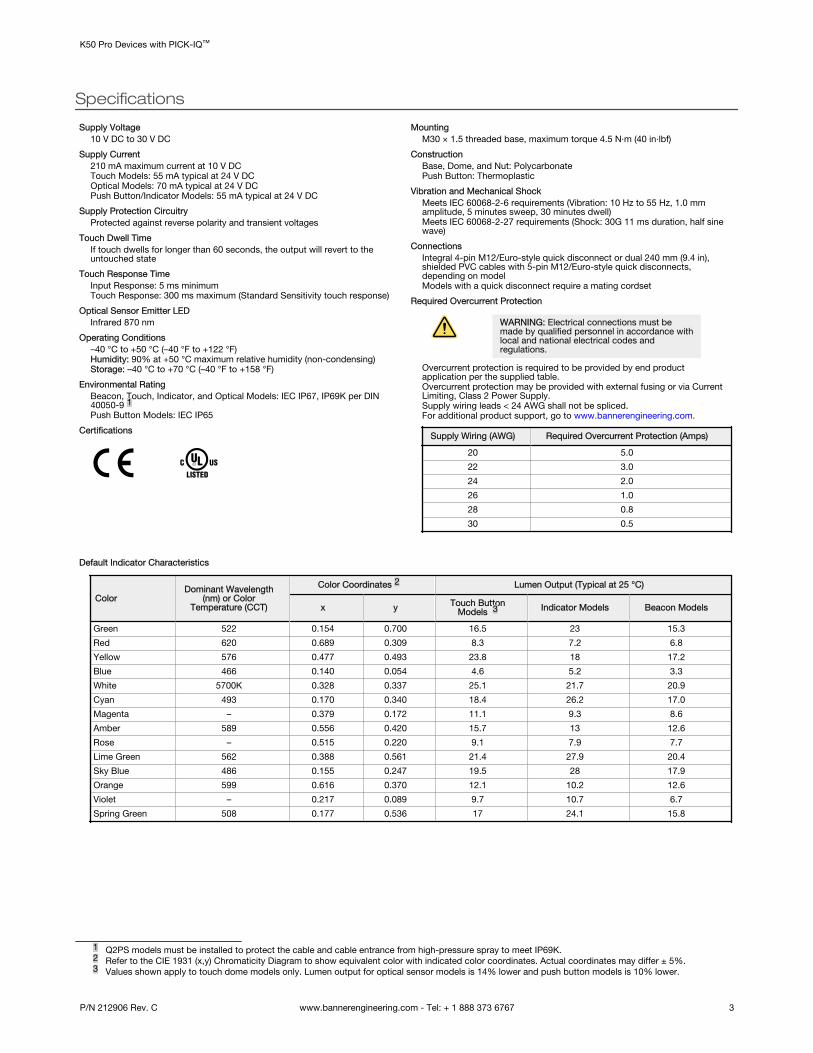
Specifications
Supply Voltage10 V DC to 30 V DC
Supply Current210 mA maximum current at 10 V DCTouch Models: 55 mA typical at 24 V DCOptical Models: 70 mA typical at 24 V DCPush Button/Indicator Models: 55 mA typical at 24 V DC
Supply Protection CircuitryProtected against reverse polarity and transient voltages
Touch Dwell TimeIf touch dwells for longer than 60 seconds, the output will revert to theuntouched state
Touch Response TimeInput Response: 5 ms minimumTouch Response: 300 ms maximum (Standard Sensitivity touch response)
Optical Sensor Emitter LEDInfrared 870 nm
Operating Conditions–40 °C to +50 °C (–40 °F to +122 °F)Humidity: 90% at +50 °C maximum relative humidity (non-condensing)Storage: –40 °C to +70 °C (–40 °F to +158 °F)
Environmental RatingBeacon, Touch, Indicator, and Optical Models: IEC IP67, IP69K per DIN40050-9 1Push Button Models: IEC IP65
Certifications
MountingM30 × 1.5 threaded base, maximum torque 4.5 N·m (40 in·lbf)
ConstructionBase, Dome, and Nut: PolycarbonatePush Button: Thermoplastic
Vibration and Mechanical ShockMeets IEC 60068-2-6 requirements (Vibration: 10 Hz to 55 Hz, 1.0 mmamplitude, 5 minutes sweep, 30 minutes dwell)Meets IEC 60068-2-27 requirements (Shock: 30G 11 ms duration, half sinewave)
ConnectionsIntegral 4-pin M12/Euro-style quick disconnect or dual 240 mm (9.4 in),shielded PVC cables with 5-pin M12/Euro-style quick disconnects,depending on modelModels with a quick disconnect require a mating cordset
Required Overcurrent Protection
WARNING: Electrical connections must bemade by qualified personnel in accordance withlocal and national electrical codes andregulations.
Overcurrent protection is required to be provided by end productapplication per the supplied table.Overcurrent protection may be provided with external fusing or via CurrentLimiting, Class 2 Power Supply.Supply wiring leads < 24 AWG shall not be spliced.For additional product support, go to www.bannerengineering.com.
Supply Wiring (AWG) Required Overcurrent Protection (Amps)
20 5.0
22 3.0
24 2.0
26 1.0
28 0.8
30 0.5
Default Indicator Characteristics
ColorDominant Wavelength
(nm) or ColorTemperature (CCT)
Color Coordinates 2 Lumen Output (Typical at 25 °C)
x y Touch ButtonModels 3 Indicator Models Beacon Models
Green 522 0.154 0.700 16.5 23 15.3
Red 620 0.689 0.309 8.3 7.2 6.8
Yellow 576 0.477 0.493 23.8 18 17.2
Blue 466 0.140 0.054 4.6 5.2 3.3
White 5700K 0.328 0.337 25.1 21.7 20.9
Cyan 493 0.170 0.340 18.4 26.2 17.0
Magenta – 0.379 0.172 11.1 9.3 8.6
Amber 589 0.556 0.420 15.7 13 12.6
Rose – 0.515 0.220 9.1 7.9 7.7
Lime Green 562 0.388 0.561 21.4 27.9 20.4
Sky Blue 486 0.155 0.247 19.5 28 17.9
Orange 599 0.616 0.370 12.1 10.2 12.6
Violet – 0.217 0.089 9.7 10.7 6.7
Spring Green 508 0.177 0.536 17 24.1 15.8
1 Q2PS models must be installed to protect the cable and cable entrance from high-pressure spray to meet IP69K.2 Refer to the CIE 1931 (x,y) Chromaticity Diagram to show equivalent color with indicated color coordinates. Actual coordinates may differ ± 5%.3 Values shown apply to touch dome models only. Lumen output for optical sensor models is 14% lower and push button models is 10% lower.
K50 Pro Devices with PICK-IQ™
P/N 212906 Rev. C www.bannerengineering.com - Tel: + 1 888 373 6767 3

DimensionsAll measurements are listed in millimeters [inches], unless noted otherwise. Compatible brackets can be found in the PICK-IQ™
Devices Instruction Manual (206185).
Touch Button
Ø50 mm[1.97”]
66 mm[2.6”]
55 mm[2.17”]
35 mm[1.38”]
M30 x 1.5
M12 x 1
Indicator 50.0 mm (1.97")
38 mm (1.50")
20 mm (0.79")
11 mm (0.43")
M30 x 1.5(mounting nut
included)
Internal Threads ½ - 14 NPT
Max. Torque 4.5 Nm (40 in-lbf)
Max. Torque 2.25 Nm(20 in-lbf)
Push Button Optical Sensor
M30 × 1.5
M12 × 1
Ø50.0 mm[1.97”]
Ø17.4 mm[0.69”]
74.7 mm[2.94”]
63.7 mm[2.51”]
43.7 mm[1.72”]
Beacon Dual M12/Euro-style Cable
M12
M30 x 1.5(mounting nut included)Max. torque 4.5 Nm (40 in.-lbs)
501.97[ ]
49[1.93]
11[.43]
29[1.14]
Internal Threads1/2 - 14 NPSMMax. torque 2.25 Nm (20 in.-lbs)
240.0 [9.45]
M12 x 1
Note: The splitter cordset dimensions are functionally identical for all K50 devices; the K50 Indicator is shown.
K50 Pro Devices with PICK-IQ™
4 www.bannerengineering.com - Tel: + 1 888 373 6767 P/N 212906 Rev. C

Banner Engineering Corp. Limited WarrantyBanner Engineering Corp. warrants its products to be free from defects in material and workmanship for one year following the date of shipment. Banner Engineering Corp. will repair orreplace, free of charge, any product of its manufacture which, at the time it is returned to the factory, is found to have been defective during the warranty period. This warranty does notcover damage or liability for misuse, abuse, or the improper application or installation of the Banner product.
THIS LIMITED WARRANTY IS EXCLUSIVE AND IN LIEU OF ALL OTHER WARRANTIES WHETHER EXPRESS OR IMPLIED (INCLUDING, WITHOUT LIMITATION, ANY WARRANTY OFMERCHANTABILITY OR FITNESS FOR A PARTICULAR PURPOSE), AND WHETHER ARISING UNDER COURSE OF PERFORMANCE, COURSE OF DEALING OR TRADE USAGE.
This Warranty is exclusive and limited to repair or, at the discretion of Banner Engineering Corp., replacement. IN NO EVENT SHALL BANNER ENGINEERING CORP. BE LIABLE TOBUYER OR ANY OTHER PERSON OR ENTITY FOR ANY EXTRA COSTS, EXPENSES, LOSSES, LOSS OF PROFITS, OR ANY INCIDENTAL, CONSEQUENTIAL OR SPECIAL DAMAGESRESULTING FROM ANY PRODUCT DEFECT OR FROM THE USE OR INABILITY TO USE THE PRODUCT, WHETHER ARISING IN CONTRACT OR WARRANTY, STATUTE, TORT,STRICT LIABILITY, NEGLIGENCE, OR OTHERWISE.
Banner Engineering Corp. reserves the right to change, modify or improve the design of the product without assuming any obligations or liabilities relating to any product previouslymanufactured by Banner Engineering Corp. Any misuse, abuse, or improper application or installation of this product or use of the product for personal protection applications when theproduct is identified as not intended for such purposes will void the product warranty. Any modifications to this product without prior express approval by Banner Engineering Corp willvoid the product warranties. All specifications published in this document are subject to change; Banner reserves the right to modify product specifications or update documentation atany time. Specifications and product information in English supersede that which is provided in any other language. For the most recent version of any documentation, refer to: www.bannerengineering.com.
For patent information, see www.bannerengineering.com/patents.
FCC Part 15 and CAN ICES-3 (B)/NMB-3(B)This device complies with part 15 of the FCC Rules and CAN ICES-3 (B)/NMB-3(B). Operation is subject to the following two conditions:
1. This device may not cause harmful interference, and2. This device must accept any interference received, including interference that may cause undesired operation.
This equipment has been tested and found to comply with the limits for a Class B digital device, pursuant to part 15 of the FCC Rules and CAN ICES-3 (B)/NMB-3(B). These limits aredesigned to provide reasonable protection against harmful interference in a residential installation. This equipment generates, uses and can radiate radio frequency energy and, if notinstalled and used in accordance with the instructions, may cause harmful interference to radio communications. However, there is no guarantee that interference will not occur in aparticular installation. If this equipment does cause harmful interference to radio or television reception, which can be determined by turning the equipment off and on, the user isencouraged to try to correct the interference by one or more of the following measures:
• Reorient or relocate the receiving antenna.• Increase the separation between the equipment and receiver.• Connect the equipment into an outlet on a circuit different from that to which the receiver is connected.• Consult the manufacturer.
K50 Pro Devices with PICK-IQ™
© Banner Engineering Corp. All rights reserved