Embed Size (px)
Citation preview

Junos®OS
Network Address Translation Feature Guide forSecurity Devices
Modified: 2018-10-02
Copyright © 2018, Juniper Networks, Inc.

Juniper Networks, Inc.1133 InnovationWaySunnyvale, California 94089USA408-745-2000www.juniper.net
Juniper Networks, the Juniper Networks logo, Juniper, and Junos are registered trademarks of Juniper Networks, Inc. and/or its affiliates inthe United States and other countries. All other trademarks may be property of their respective owners.
Juniper Networks assumes no responsibility for any inaccuracies in this document. Juniper Networks reserves the right to change, modify,transfer, or otherwise revise this publication without notice.
Junos®OS Network Address Translation Feature Guide for Security Devices
Copyright © 2018 Juniper Networks, Inc. All rights reserved.
The information in this document is current as of the date on the title page.
YEAR 2000 NOTICE
Juniper Networks hardware and software products are Year 2000 compliant. Junos OS has no known time-related limitations through theyear 2038. However, the NTP application is known to have some difficulty in the year 2036.
ENDUSER LICENSE AGREEMENT
The Juniper Networks product that is the subject of this technical documentation consists of (or is intended for use with) Juniper Networkssoftware. Use of such software is subject to the terms and conditions of the End User License Agreement (“EULA”) posted athttps://support.juniper.net/support/eula/. By downloading, installing or using such software, you agree to the terms and conditions ofthat EULA.
Copyright © 2018, Juniper Networks, Inc.ii

Table of Contents
About the Documentation . . . . . . . . . . . . . . . . . . . . . . . . . . . . . . . . . . . . . . . . . . . . xiii
Documentation and Release Notes . . . . . . . . . . . . . . . . . . . . . . . . . . . . . . . . . xiii
Using the Examples in This Manual . . . . . . . . . . . . . . . . . . . . . . . . . . . . . . . . . xiii
Merging a Full Example . . . . . . . . . . . . . . . . . . . . . . . . . . . . . . . . . . . . . . . xiv
Merging a Snippet . . . . . . . . . . . . . . . . . . . . . . . . . . . . . . . . . . . . . . . . . . . xiv
Documentation Conventions . . . . . . . . . . . . . . . . . . . . . . . . . . . . . . . . . . . . . . xv
Documentation Feedback . . . . . . . . . . . . . . . . . . . . . . . . . . . . . . . . . . . . . . . . xvii
Requesting Technical Support . . . . . . . . . . . . . . . . . . . . . . . . . . . . . . . . . . . . xvii
Self-Help Online Tools and Resources . . . . . . . . . . . . . . . . . . . . . . . . . . xviii
Opening a Case with JTAC . . . . . . . . . . . . . . . . . . . . . . . . . . . . . . . . . . . . xviii
Chapter 1 Overview . . . . . . . . . . . . . . . . . . . . . . . . . . . . . . . . . . . . . . . . . . . . . . . . . . . . . . . . . 19
NAT Overview . . . . . . . . . . . . . . . . . . . . . . . . . . . . . . . . . . . . . . . . . . . . . . . . . . . . . . 19
Introduction to NAT . . . . . . . . . . . . . . . . . . . . . . . . . . . . . . . . . . . . . . . . . . . . . . 19
Understanding NAT Rule Sets and Rules . . . . . . . . . . . . . . . . . . . . . . . . . . . . . 20
NAT Rule Sets . . . . . . . . . . . . . . . . . . . . . . . . . . . . . . . . . . . . . . . . . . . . . . 20
NAT Rules . . . . . . . . . . . . . . . . . . . . . . . . . . . . . . . . . . . . . . . . . . . . . . . . . . 21
Rule Processing . . . . . . . . . . . . . . . . . . . . . . . . . . . . . . . . . . . . . . . . . . . . . 22
NAT Rule Capacity . . . . . . . . . . . . . . . . . . . . . . . . . . . . . . . . . . . . . . . . . . . 23
NAT Configuration Overview . . . . . . . . . . . . . . . . . . . . . . . . . . . . . . . . . . . . . . . . . . 24
Configuring NAT Using the NAT Wizard . . . . . . . . . . . . . . . . . . . . . . . . . . . . . . 24
Example: Configuring NAT for Multiple ISPs . . . . . . . . . . . . . . . . . . . . . . . . . . 24
Configuring Proxy ARP for NAT (CLI Procedure) . . . . . . . . . . . . . . . . . . . . . . . 37
Configuring NAT trace options . . . . . . . . . . . . . . . . . . . . . . . . . . . . . . . . . . . . . 37
Monitoring NAT Incoming Table Information . . . . . . . . . . . . . . . . . . . . . . . . . . 39
Monitoring Interface NAT Port Information . . . . . . . . . . . . . . . . . . . . . . . . . . . 39
Chapter 2 Types of NAT . . . . . . . . . . . . . . . . . . . . . . . . . . . . . . . . . . . . . . . . . . . . . . . . . . . . . . 41
Source NAT . . . . . . . . . . . . . . . . . . . . . . . . . . . . . . . . . . . . . . . . . . . . . . . . . . . . . . . . 41
Understanding Source NAT . . . . . . . . . . . . . . . . . . . . . . . . . . . . . . . . . . . . . . . 42
Understanding Central Point Architecture Enhancements for NAT . . . . . . . . 43
Optimizing Source NAT Performance . . . . . . . . . . . . . . . . . . . . . . . . . . . . . . . 44
Port Randomization Mode (Default) . . . . . . . . . . . . . . . . . . . . . . . . . . . . 44
Round-Robin Mode . . . . . . . . . . . . . . . . . . . . . . . . . . . . . . . . . . . . . . . . . . 44
Session Affinity Mode . . . . . . . . . . . . . . . . . . . . . . . . . . . . . . . . . . . . . . . . 45
Monitoring Source NAT Information . . . . . . . . . . . . . . . . . . . . . . . . . . . . . . . . 46
Source NAT Configuration Overview . . . . . . . . . . . . . . . . . . . . . . . . . . . . . . . . . 51
Example: Configuring Source NAT for Egress Interface Translation . . . . . . . . 52
Example: Configuring Source NAT for Single Address Translation . . . . . . . . . 56
Example: Configuring Source and Destination NAT Translations . . . . . . . . . . 60
Understanding Source NAT Rules . . . . . . . . . . . . . . . . . . . . . . . . . . . . . . . . . . 67
iiiCopyright © 2018, Juniper Networks, Inc.

Example: Configuring Source NAT with Multiple Rules . . . . . . . . . . . . . . . . . . 68
Understanding Source NAT Pools . . . . . . . . . . . . . . . . . . . . . . . . . . . . . . . . . . 75
Understanding Source NAT Pool Capacities . . . . . . . . . . . . . . . . . . . . . . . . . . 77
Understanding Persistent Addresses for Source NAT Pools . . . . . . . . . . . . . . 78
Example: Configuring Capacity for Source NAT Pools with PAT . . . . . . . . . . . 78
Understanding Source NAT Pools with Address Pooling . . . . . . . . . . . . . . . . 80
Understanding Source NAT Pools with Address Shifting . . . . . . . . . . . . . . . . 80
Example: Configuring Source NAT Pools with Address Shifting . . . . . . . . . . . 81
Understanding Source NAT Pools with PAT . . . . . . . . . . . . . . . . . . . . . . . . . . 86
Example: Configuring Source NAT for Multiple Addresses with PAT . . . . . . . . 87
Understanding Source NAT Pools Without PAT . . . . . . . . . . . . . . . . . . . . . . . 92
Example: Configuring a Single IP Address in a Source NAT Pool Without
PAT . . . . . . . . . . . . . . . . . . . . . . . . . . . . . . . . . . . . . . . . . . . . . . . . . . . . . . . 92
Example: Configuring Multiple Addresses in a Source NAT Pool Without
PAT . . . . . . . . . . . . . . . . . . . . . . . . . . . . . . . . . . . . . . . . . . . . . . . . . . . . . . . 96
Understanding Shared Addresses in Source NAT Pools without PAT . . . . . . 101
Understanding NAT Session Persistence . . . . . . . . . . . . . . . . . . . . . . . . . . . . 101
Limitations of NAT Session Persistence . . . . . . . . . . . . . . . . . . . . . . . . . 102
Configuring the NAT Session Hold Timeout and NAT Session Persistence
Scan . . . . . . . . . . . . . . . . . . . . . . . . . . . . . . . . . . . . . . . . . . . . . . . . . . . . . 102
Understanding NAT Configuration Check on Egress Interfaces after
Reroute . . . . . . . . . . . . . . . . . . . . . . . . . . . . . . . . . . . . . . . . . . . . . . . . . . . 103
Destination NAT . . . . . . . . . . . . . . . . . . . . . . . . . . . . . . . . . . . . . . . . . . . . . . . . . . . 105
Understanding Destination NAT . . . . . . . . . . . . . . . . . . . . . . . . . . . . . . . . . . . 106
Understanding Destination NAT Address Pools . . . . . . . . . . . . . . . . . . . . . . 106
Understanding Destination NAT Rules . . . . . . . . . . . . . . . . . . . . . . . . . . . . . . 107
Destination NAT Configuration Overview . . . . . . . . . . . . . . . . . . . . . . . . . . . . 108
Example: Configuring Destination NAT for Single Address Translation . . . . 108
Example: Configuring Destination NAT for IP Address and Port
Translation . . . . . . . . . . . . . . . . . . . . . . . . . . . . . . . . . . . . . . . . . . . . . . . . . 115
Example: Configuring Destination NAT for Subnet Translation . . . . . . . . . . . 121
Monitoring Destination NAT Information . . . . . . . . . . . . . . . . . . . . . . . . . . . . 127
Static NAT . . . . . . . . . . . . . . . . . . . . . . . . . . . . . . . . . . . . . . . . . . . . . . . . . . . . . . . . 128
Understanding Static NAT . . . . . . . . . . . . . . . . . . . . . . . . . . . . . . . . . . . . . . . . 129
Understanding Static NAT Rules . . . . . . . . . . . . . . . . . . . . . . . . . . . . . . . . . . . 129
Static NAT Configuration Overview . . . . . . . . . . . . . . . . . . . . . . . . . . . . . . . . 130
Example: Configuring Static NAT for Single Address Translation . . . . . . . . . 130
Example: Configuring Static NAT for Subnet Translation . . . . . . . . . . . . . . . 136
Example: Configuring Static NAT for Port Mapping . . . . . . . . . . . . . . . . . . . . 141
Monitoring Static NAT Information . . . . . . . . . . . . . . . . . . . . . . . . . . . . . . . . . 147
Chapter 3 NAT Configuration Options . . . . . . . . . . . . . . . . . . . . . . . . . . . . . . . . . . . . . . . . . 151
Persistent NAT and NAT64 . . . . . . . . . . . . . . . . . . . . . . . . . . . . . . . . . . . . . . . . . . . 151
Understanding Persistent NAT and NAT64 . . . . . . . . . . . . . . . . . . . . . . . . . . . 151
Understanding Session Traversal Utilities for NAT (STUN) Protocol . . . . . . 153
Copyright © 2018, Juniper Networks, Inc.iv
Network Address Translation Feature Guide for Security Devices
Understanding NAT64 IPv6 Prefix to IPv4 Address-Persistent
Translation . . . . . . . . . . . . . . . . . . . . . . . . . . . . . . . . . . . . . . . . . . . . . . . . 154
Persistent NAT and NAT64 Configuration Overview . . . . . . . . . . . . . . . . . . . 155
Example: Configuring Address Persistent NAT64 Pools . . . . . . . . . . . . . . . . 157
Example: Supporting Network Configuration By Configuring Persistent NAT
with Interface NAT . . . . . . . . . . . . . . . . . . . . . . . . . . . . . . . . . . . . . . . . . . 159
Example: Configuring Address-Dependent Filtering for IPv6 Clients . . . . . . 165
Example: Configuring Endpoint-Independent Filtering for IPv6 Clients . . . . 169
Example: Setting Maximum Persistent NAT Bindings . . . . . . . . . . . . . . . . . . 172
Persistent NAT Hairpinning Overview . . . . . . . . . . . . . . . . . . . . . . . . . . . . . . . 174
Example: Configuring Persistent NAT Hairpinning with Source NAT Pool
with Address Shifting . . . . . . . . . . . . . . . . . . . . . . . . . . . . . . . . . . . . . . . . 174
NAT for Multicast Flows . . . . . . . . . . . . . . . . . . . . . . . . . . . . . . . . . . . . . . . . . . . . . 180
Understanding NAT for Multicast Flows . . . . . . . . . . . . . . . . . . . . . . . . . . . . . 180
Example: Configuring NAT for Multicast Flows . . . . . . . . . . . . . . . . . . . . . . . . 181
IPv6 NAT . . . . . . . . . . . . . . . . . . . . . . . . . . . . . . . . . . . . . . . . . . . . . . . . . . . . . . . . . 191
IPv6 NAT Overview . . . . . . . . . . . . . . . . . . . . . . . . . . . . . . . . . . . . . . . . . . . . . . 191
Source NAT Translations Supported by IPv6 NAT . . . . . . . . . . . . . . . . . . 191
Destination NAT Mappings Supported by IPv6 NAT . . . . . . . . . . . . . . . . 192
Static NAT Mappings Supported by IPv6 NAT . . . . . . . . . . . . . . . . . . . . 192
IPv6 NAT PT Overview . . . . . . . . . . . . . . . . . . . . . . . . . . . . . . . . . . . . . . . . . . 193
IPv6 NAT-PT Communication Overview . . . . . . . . . . . . . . . . . . . . . . . . . . . . 194
Example: Configuring an IPv4-Initiated Connection to an IPv6 Node Using
Default Destination Address Prefix Static Mapping . . . . . . . . . . . . . . . . 194
Example: Configuring an IPv4-Initiated Connection to an IPv6 Node Using
Static Destination Address One-to-One Mapping . . . . . . . . . . . . . . . . . 198
Example: Configuring an IPv6-Initiated Connection to an IPv4 Node Using
Default Destination Address Prefix Static Mapping . . . . . . . . . . . . . . . . 201
Example: Configuring an IPv6-Initiated Connection to an IPv4 Node Using
Static Destination Address One-to-One Mapping . . . . . . . . . . . . . . . . . 206
IPv6 Dual-Stack Lite . . . . . . . . . . . . . . . . . . . . . . . . . . . . . . . . . . . . . . . . . . . . . . . 209
Understanding IPv6 Dual-Stack Lite . . . . . . . . . . . . . . . . . . . . . . . . . . . . . . . 209
Example: Configuring IPv6 Dual-Stack Lite . . . . . . . . . . . . . . . . . . . . . . . . . . 212
Chapter 4 Configuration Statements . . . . . . . . . . . . . . . . . . . . . . . . . . . . . . . . . . . . . . . . . 215
address (Security ARP Proxy) . . . . . . . . . . . . . . . . . . . . . . . . . . . . . . . . . . . . . . . . 218
address (Security Destination NAT) . . . . . . . . . . . . . . . . . . . . . . . . . . . . . . . . . . . 218
address (Security NDP Proxy) . . . . . . . . . . . . . . . . . . . . . . . . . . . . . . . . . . . . . . . . 219
address-mapping . . . . . . . . . . . . . . . . . . . . . . . . . . . . . . . . . . . . . . . . . . . . . . . . . 220
address-persistent (Security Source NAT) . . . . . . . . . . . . . . . . . . . . . . . . . . . . . . 220
address-persistent (Security Source NAT Pool) . . . . . . . . . . . . . . . . . . . . . . . . . . 221
address-pooling (Security Source NAT) . . . . . . . . . . . . . . . . . . . . . . . . . . . . . . . . 222
address-shared (Security Source NAT) . . . . . . . . . . . . . . . . . . . . . . . . . . . . . . . . . 223
application (Security Destination NAT) . . . . . . . . . . . . . . . . . . . . . . . . . . . . . . . . 224
application (Security Source NAT) . . . . . . . . . . . . . . . . . . . . . . . . . . . . . . . . . . . . 225
application-services (Security Forwarding Process) . . . . . . . . . . . . . . . . . . . . . . 226
clear-threshold . . . . . . . . . . . . . . . . . . . . . . . . . . . . . . . . . . . . . . . . . . . . . . . . . . . . 227
description (Security NAT Pool) . . . . . . . . . . . . . . . . . . . . . . . . . . . . . . . . . . . . . . 228
description (Security NAT Rule) . . . . . . . . . . . . . . . . . . . . . . . . . . . . . . . . . . . . . . 229
vCopyright © 2018, Juniper Networks, Inc.
Table of Contents

description (Security NAT Rule Set) . . . . . . . . . . . . . . . . . . . . . . . . . . . . . . . . . . . 230
destination (Security Destination NAT) . . . . . . . . . . . . . . . . . . . . . . . . . . . . . . . . . 231
destination-address (Security Destination NAT) . . . . . . . . . . . . . . . . . . . . . . . . . 232
destination-address (Security Source NAT) . . . . . . . . . . . . . . . . . . . . . . . . . . . . . 233
destination-address (Security Static NAT) . . . . . . . . . . . . . . . . . . . . . . . . . . . . . . 233
destination-address-name (Security Destination NAT) . . . . . . . . . . . . . . . . . . . 234
destination-address-name (Security Source NAT) . . . . . . . . . . . . . . . . . . . . . . . 234
destination-address-name (Security Static NAT) . . . . . . . . . . . . . . . . . . . . . . . . 235
destination-nat . . . . . . . . . . . . . . . . . . . . . . . . . . . . . . . . . . . . . . . . . . . . . . . . . . . 236
destination-port (Security Destination NAT) . . . . . . . . . . . . . . . . . . . . . . . . . . . . 237
destination-port (Security Source NAT) . . . . . . . . . . . . . . . . . . . . . . . . . . . . . . . . 238
destination-port (Security Static NAT) . . . . . . . . . . . . . . . . . . . . . . . . . . . . . . . . . 239
enable-reroute-uniform-link-check . . . . . . . . . . . . . . . . . . . . . . . . . . . . . . . . . . . 240
from (Security NAT) . . . . . . . . . . . . . . . . . . . . . . . . . . . . . . . . . . . . . . . . . . . . . . . . 241
host-address-base . . . . . . . . . . . . . . . . . . . . . . . . . . . . . . . . . . . . . . . . . . . . . . . . . 241
inactivity-timeout (Security Persistent NAT) . . . . . . . . . . . . . . . . . . . . . . . . . . . . 242
inet (Security Static NAT) . . . . . . . . . . . . . . . . . . . . . . . . . . . . . . . . . . . . . . . . . . . 243
interface (Security NAT ARP Proxy) . . . . . . . . . . . . . . . . . . . . . . . . . . . . . . . . . . . 244
interface (Security NAT NDP Proxy) . . . . . . . . . . . . . . . . . . . . . . . . . . . . . . . . . . . 245
interface (Security Source NAT) . . . . . . . . . . . . . . . . . . . . . . . . . . . . . . . . . . . . . . 246
interface (Security Source NAT Rule Set) . . . . . . . . . . . . . . . . . . . . . . . . . . . . . . . 246
interim-logging-interval . . . . . . . . . . . . . . . . . . . . . . . . . . . . . . . . . . . . . . . . . . . . . 247
last-block-recycle-timeout . . . . . . . . . . . . . . . . . . . . . . . . . . . . . . . . . . . . . . . . . . 248
mapped-port (Security Static NAT) . . . . . . . . . . . . . . . . . . . . . . . . . . . . . . . . . . . 249
match (Security Destination NAT) . . . . . . . . . . . . . . . . . . . . . . . . . . . . . . . . . . . . 250
match (Security Source NAT) . . . . . . . . . . . . . . . . . . . . . . . . . . . . . . . . . . . . . . . . . 251
match (Security Static NAT) . . . . . . . . . . . . . . . . . . . . . . . . . . . . . . . . . . . . . . . . . 252
max-session-number . . . . . . . . . . . . . . . . . . . . . . . . . . . . . . . . . . . . . . . . . . . . . . . 252
overflow-pool . . . . . . . . . . . . . . . . . . . . . . . . . . . . . . . . . . . . . . . . . . . . . . . . . . . . . 253
nptv6-prefix . . . . . . . . . . . . . . . . . . . . . . . . . . . . . . . . . . . . . . . . . . . . . . . . . . . . . . 254
nptv6-prefix-name . . . . . . . . . . . . . . . . . . . . . . . . . . . . . . . . . . . . . . . . . . . . . . . . 254
permit (Security Persistent NAT) . . . . . . . . . . . . . . . . . . . . . . . . . . . . . . . . . . . . . 255
persistent-nat . . . . . . . . . . . . . . . . . . . . . . . . . . . . . . . . . . . . . . . . . . . . . . . . . . . . 256
pool (Security Destination NAT) . . . . . . . . . . . . . . . . . . . . . . . . . . . . . . . . . . . . . . 257
pool (Security Source NAT) . . . . . . . . . . . . . . . . . . . . . . . . . . . . . . . . . . . . . . . . . . 258
pool (Security Source NAT Rule Set) . . . . . . . . . . . . . . . . . . . . . . . . . . . . . . . . . . 259
pool-default-port-range . . . . . . . . . . . . . . . . . . . . . . . . . . . . . . . . . . . . . . . . . . . . 260
pool-default-twin-port-range . . . . . . . . . . . . . . . . . . . . . . . . . . . . . . . . . . . . . . . . 261
pool-utilization-alarm . . . . . . . . . . . . . . . . . . . . . . . . . . . . . . . . . . . . . . . . . . . . . . 262
pool-utilization-alarm (Security Source NAT Pool) . . . . . . . . . . . . . . . . . . . . . . . 263
port (Security Source NAT) . . . . . . . . . . . . . . . . . . . . . . . . . . . . . . . . . . . . . . . . . . 264
port-overloading (Security Source NAT Interface) . . . . . . . . . . . . . . . . . . . . . . . . 265
port-overloading-factor (Security Source NAT Interface) . . . . . . . . . . . . . . . . . . 266
port-overloading-factor (Security Source NAT Pool) . . . . . . . . . . . . . . . . . . . . . . 267
port-randomization . . . . . . . . . . . . . . . . . . . . . . . . . . . . . . . . . . . . . . . . . . . . . . . . 268
port-round-robin . . . . . . . . . . . . . . . . . . . . . . . . . . . . . . . . . . . . . . . . . . . . . . . . . . 268
port-scaling-enlargement . . . . . . . . . . . . . . . . . . . . . . . . . . . . . . . . . . . . . . . . . . . 269
prefix (Security Static NAT) . . . . . . . . . . . . . . . . . . . . . . . . . . . . . . . . . . . . . . . . . . 270
prefix-name (Security Static NAT) . . . . . . . . . . . . . . . . . . . . . . . . . . . . . . . . . . . . . 271
Copyright © 2018, Juniper Networks, Inc.vi
Network Address Translation Feature Guide for Security Devices
protocol (Security Destination NAT) . . . . . . . . . . . . . . . . . . . . . . . . . . . . . . . . . . . 272
protocol (Security Source NAT) . . . . . . . . . . . . . . . . . . . . . . . . . . . . . . . . . . . . . . . 272
proxy-arp (Security NAT) . . . . . . . . . . . . . . . . . . . . . . . . . . . . . . . . . . . . . . . . . . . . 273
proxy-ndp (Security NAT) . . . . . . . . . . . . . . . . . . . . . . . . . . . . . . . . . . . . . . . . . . . 274
raise-threshold . . . . . . . . . . . . . . . . . . . . . . . . . . . . . . . . . . . . . . . . . . . . . . . . . . . . 274
routing-instance (Security Destination NAT) . . . . . . . . . . . . . . . . . . . . . . . . . . . . 275
routing-instance (Security Source NAT) . . . . . . . . . . . . . . . . . . . . . . . . . . . . . . . . 275
rule (Security Destination NAT) . . . . . . . . . . . . . . . . . . . . . . . . . . . . . . . . . . . . . . . 276
rule (Security Source NAT) . . . . . . . . . . . . . . . . . . . . . . . . . . . . . . . . . . . . . . . . . . . 277
rule (Security Static NAT) . . . . . . . . . . . . . . . . . . . . . . . . . . . . . . . . . . . . . . . . . . . 279
rule-session-count-alarm (Security Destination NAT Rule Set) . . . . . . . . . . . . . 280
rule-session-count-alarm (Security Source NAT Rule Set) . . . . . . . . . . . . . . . . . 281
rule-session-count-alarm (Security Static NAT Rule Set) . . . . . . . . . . . . . . . . . . 282
rule-set (Security Destination NAT) . . . . . . . . . . . . . . . . . . . . . . . . . . . . . . . . . . . 283
rule-set (Security Source NAT) . . . . . . . . . . . . . . . . . . . . . . . . . . . . . . . . . . . . . . . 285
rule-set (Security Static NAT) . . . . . . . . . . . . . . . . . . . . . . . . . . . . . . . . . . . . . . . . 287
source (Security Source NAT) . . . . . . . . . . . . . . . . . . . . . . . . . . . . . . . . . . . . . . . . 289
session-drop-hold-down . . . . . . . . . . . . . . . . . . . . . . . . . . . . . . . . . . . . . . . . . . . . 291
session-persistence-scan . . . . . . . . . . . . . . . . . . . . . . . . . . . . . . . . . . . . . . . . . . . 292
source-address (Security Destination NAT) . . . . . . . . . . . . . . . . . . . . . . . . . . . . . 292
source-address (Security Source NAT) . . . . . . . . . . . . . . . . . . . . . . . . . . . . . . . . . 293
source-address (Security Static NAT Rule Set) . . . . . . . . . . . . . . . . . . . . . . . . . . 293
source-address-name (Security Destination NAT) . . . . . . . . . . . . . . . . . . . . . . . 294
source-address-name (Security Source NAT) . . . . . . . . . . . . . . . . . . . . . . . . . . . 294
source-address-name (Security Static NAT Rule Set) . . . . . . . . . . . . . . . . . . . . 295
source-nat . . . . . . . . . . . . . . . . . . . . . . . . . . . . . . . . . . . . . . . . . . . . . . . . . . . . . . . 296
source-port (Security Source NAT Rule Set) . . . . . . . . . . . . . . . . . . . . . . . . . . . . 297
source-port (Security Static NAT Rule Set) . . . . . . . . . . . . . . . . . . . . . . . . . . . . . 297
static (Security NAT) . . . . . . . . . . . . . . . . . . . . . . . . . . . . . . . . . . . . . . . . . . . . . . . 298
static-nat . . . . . . . . . . . . . . . . . . . . . . . . . . . . . . . . . . . . . . . . . . . . . . . . . . . . . . . . 299
to (Security Source NAT) . . . . . . . . . . . . . . . . . . . . . . . . . . . . . . . . . . . . . . . . . . . 300
then (Security Destination NAT) . . . . . . . . . . . . . . . . . . . . . . . . . . . . . . . . . . . . . . 301
then (Security Source NAT) . . . . . . . . . . . . . . . . . . . . . . . . . . . . . . . . . . . . . . . . . . 302
then (Security Static NAT) . . . . . . . . . . . . . . . . . . . . . . . . . . . . . . . . . . . . . . . . . . 303
traceoptions (Security NAT) . . . . . . . . . . . . . . . . . . . . . . . . . . . . . . . . . . . . . . . . . 304
Chapter 5 Operational Commands . . . . . . . . . . . . . . . . . . . . . . . . . . . . . . . . . . . . . . . . . . 307
clear security nat incoming-table . . . . . . . . . . . . . . . . . . . . . . . . . . . . . . . . . . . . . 308
clear security nat source persistent-nat-table . . . . . . . . . . . . . . . . . . . . . . . . . . . 309
clear security nat statistics destination pool . . . . . . . . . . . . . . . . . . . . . . . . . . . . . 310
clear security nat statistics destination rule . . . . . . . . . . . . . . . . . . . . . . . . . . . . . . 311
clear security nat statistics source pool . . . . . . . . . . . . . . . . . . . . . . . . . . . . . . . . . 312
clear security nat statistics source rule . . . . . . . . . . . . . . . . . . . . . . . . . . . . . . . . . 313
clear security nat statistics static rule . . . . . . . . . . . . . . . . . . . . . . . . . . . . . . . . . . 314
show security nat destination pool . . . . . . . . . . . . . . . . . . . . . . . . . . . . . . . . . . . . 315
show security nat destination rule . . . . . . . . . . . . . . . . . . . . . . . . . . . . . . . . . . . . . 318
show security nat destination rule-application . . . . . . . . . . . . . . . . . . . . . . . . . . . 322
show security nat destination summary . . . . . . . . . . . . . . . . . . . . . . . . . . . . . . . . 324
show security nat incoming-table . . . . . . . . . . . . . . . . . . . . . . . . . . . . . . . . . . . . . 327
viiCopyright © 2018, Juniper Networks, Inc.
Table of Contents

show security nat interface-nat-ports . . . . . . . . . . . . . . . . . . . . . . . . . . . . . . . . . 329
show security nat resource-usage source-pool . . . . . . . . . . . . . . . . . . . . . . . . . . 332
show security nat source deterministic . . . . . . . . . . . . . . . . . . . . . . . . . . . . . . . . . 335
show security nat source paired-address . . . . . . . . . . . . . . . . . . . . . . . . . . . . . . . 337
show security nat source persistent-nat-table . . . . . . . . . . . . . . . . . . . . . . . . . . 340
show security nat source pool . . . . . . . . . . . . . . . . . . . . . . . . . . . . . . . . . . . . . . . . 343
show security nat source port-block . . . . . . . . . . . . . . . . . . . . . . . . . . . . . . . . . . . 349
show security nat source rule . . . . . . . . . . . . . . . . . . . . . . . . . . . . . . . . . . . . . . . . 352
show security nat source rule-application . . . . . . . . . . . . . . . . . . . . . . . . . . . . . . 356
show security nat source summary . . . . . . . . . . . . . . . . . . . . . . . . . . . . . . . . . . . . 358
show security nat static rule . . . . . . . . . . . . . . . . . . . . . . . . . . . . . . . . . . . . . . . . . . 361
Copyright © 2018, Juniper Networks, Inc.viii
Network Address Translation Feature Guide for Security Devices

List of Figures
Chapter 1 Overview . . . . . . . . . . . . . . . . . . . . . . . . . . . . . . . . . . . . . . . . . . . . . . . . . . . . . . . . . 19
Figure 1: NAT Rule Processing . . . . . . . . . . . . . . . . . . . . . . . . . . . . . . . . . . . . . . . . . . 22
Chapter 2 Types of NAT . . . . . . . . . . . . . . . . . . . . . . . . . . . . . . . . . . . . . . . . . . . . . . . . . . . . . . 41
Figure 2: Source NAT Egress Interface Translation . . . . . . . . . . . . . . . . . . . . . . . . . 53
Figure 3: Source NAT Single Address Translation . . . . . . . . . . . . . . . . . . . . . . . . . . 57
Figure 4: Source and Destination NAT Translations . . . . . . . . . . . . . . . . . . . . . . . . 62
Figure 5: Source NAT with Multiple Translation Rules . . . . . . . . . . . . . . . . . . . . . . 69
Figure 6: Source NAT with Address Shifting . . . . . . . . . . . . . . . . . . . . . . . . . . . . . . 82
Figure 7: Source NAT Multiple Addresses with PAT . . . . . . . . . . . . . . . . . . . . . . . . 88
Figure 8: Source NAT Multiple Addresses Without PAT . . . . . . . . . . . . . . . . . . . . . 97
Figure 9: Destination NAT Single Address Translation . . . . . . . . . . . . . . . . . . . . . 109
Figure 10: Destination NAT Address and Port Translation . . . . . . . . . . . . . . . . . . . 117
Figure 11: Destination NAT Subnet Translation . . . . . . . . . . . . . . . . . . . . . . . . . . . . 123
Figure 12: Static NAT Single Address Translation . . . . . . . . . . . . . . . . . . . . . . . . . . 132
Figure 13: Static NAT Subnet Translation . . . . . . . . . . . . . . . . . . . . . . . . . . . . . . . . 137
Figure 14: Static NAT for Port Mapping . . . . . . . . . . . . . . . . . . . . . . . . . . . . . . . . . . 142
Chapter 3 NAT Configuration Options . . . . . . . . . . . . . . . . . . . . . . . . . . . . . . . . . . . . . . . . . 151
Figure 15: 464XLAT Architecture . . . . . . . . . . . . . . . . . . . . . . . . . . . . . . . . . . . . . . 154
Figure 16: NAT64 Translation on the PLAT (SRX Series Device) . . . . . . . . . . . . . . 155
Figure 17: Interface Persistent NAT Topology . . . . . . . . . . . . . . . . . . . . . . . . . . . . . 160
Figure 18: Persistent NAT Hairpinning . . . . . . . . . . . . . . . . . . . . . . . . . . . . . . . . . . . 176
Figure 19: NAT Translations for Multicast Flows . . . . . . . . . . . . . . . . . . . . . . . . . . 183
Figure 20: DS-Lite NAT (IPv4-in-IPv6) . . . . . . . . . . . . . . . . . . . . . . . . . . . . . . . . . 210
ixCopyright © 2018, Juniper Networks, Inc.

Copyright © 2018, Juniper Networks, Inc.x
Network Address Translation Feature Guide for Security Devices

List of Tables
About the Documentation . . . . . . . . . . . . . . . . . . . . . . . . . . . . . . . . . . . . . . . . . xiii
Table 1: Notice Icons . . . . . . . . . . . . . . . . . . . . . . . . . . . . . . . . . . . . . . . . . . . . . . . . . xv
Table 2: Text and Syntax Conventions . . . . . . . . . . . . . . . . . . . . . . . . . . . . . . . . . . xvi
Chapter 1 Overview . . . . . . . . . . . . . . . . . . . . . . . . . . . . . . . . . . . . . . . . . . . . . . . . . . . . . . . . . 19
Table 3: Number of Rules on SRX Series Devices . . . . . . . . . . . . . . . . . . . . . . . . . . 23
Table 4: Number of Rules and Rule Sets . . . . . . . . . . . . . . . . . . . . . . . . . . . . . . . . . 23
Table 5: Summary of Key Incoming Table Output Fields . . . . . . . . . . . . . . . . . . . . 39
Table 6: Summary of Key Interface NAT Output Fields . . . . . . . . . . . . . . . . . . . . . 40
Chapter 2 Types of NAT . . . . . . . . . . . . . . . . . . . . . . . . . . . . . . . . . . . . . . . . . . . . . . . . . . . . . . 41
Table 7: Source NAT Monitoring Page . . . . . . . . . . . . . . . . . . . . . . . . . . . . . . . . . . . 46
Table 8: Interfaces, Zones, Server, and IP Address Information . . . . . . . . . . . . . . . 110
Table 9: Summary of Key Destination NAT Output Fields . . . . . . . . . . . . . . . . . . . 127
Table 10: Summary of Key Static NAT Output Fields . . . . . . . . . . . . . . . . . . . . . . 148
Chapter 3 NAT Configuration Options . . . . . . . . . . . . . . . . . . . . . . . . . . . . . . . . . . . . . . . . . 151
Table 11: NAT Feature Compatibility with the Address Persistent Feature . . . . . . 155
Table 12: Interfaces, Zones, Servers, and IP Address Information . . . . . . . . . . . . . 160
Table 13: Persistent NAT Binding Table . . . . . . . . . . . . . . . . . . . . . . . . . . . . . . . . . 176
Table 14: Softwire Initiator and Softwire Concentrator Capacity . . . . . . . . . . . . . . 211
Chapter 5 Operational Commands . . . . . . . . . . . . . . . . . . . . . . . . . . . . . . . . . . . . . . . . . . 307
Table 15: show security nat destination pool Output Fields . . . . . . . . . . . . . . . . . 316
Table 16: show security nat destination rule Output Fields . . . . . . . . . . . . . . . . . . 319
Table 17: show security nat destination rule-application Output Fields . . . . . . . . 322
Table 18: show security nat destination summary Output Fields . . . . . . . . . . . . . 324
Table 19: show security nat incoming-table Output Fields . . . . . . . . . . . . . . . . . . 327
Table 20: show security nat interface-nat-ports Output Fields . . . . . . . . . . . . . . 329
Table 21: show security nat resource-usage source-pool Output Fields . . . . . . . 333
Table 22: show security nat source deterministic Output Fields . . . . . . . . . . . . . 336
Table 23: show security nat source paired-address Output Fields . . . . . . . . . . . 338
Table 24: show security nat source persistent–nat–table Output Fields . . . . . . 340
Table 25: show security nat source pool Output Fields . . . . . . . . . . . . . . . . . . . . 344
Table 26: show security nat source port-block Output Fields . . . . . . . . . . . . . . . 349
Table 27: show security nat source rule Output Fields . . . . . . . . . . . . . . . . . . . . . 353
Table 28: show security nat source rule-application Output Fields . . . . . . . . . . . 356
Table 29: show security nat source summary Output Fields . . . . . . . . . . . . . . . . 359
Table 30: show security nat static rule Output Fields . . . . . . . . . . . . . . . . . . . . . . 362
xiCopyright © 2018, Juniper Networks, Inc.

Copyright © 2018, Juniper Networks, Inc.xii
Network Address Translation Feature Guide for Security Devices

About the Documentation
• Documentation and Release Notes on page xiii
• Using the Examples in This Manual on page xiii
• Documentation Conventions on page xv
• Documentation Feedback on page xvii
• Requesting Technical Support on page xvii
Documentation and Release Notes
To obtain the most current version of all Juniper Networks®technical documentation,
see the product documentation page on the Juniper Networks website at
https://www.juniper.net/documentation/.
If the information in the latest release notes differs from the information in the
documentation, follow the product Release Notes.
Juniper Networks Books publishes books by Juniper Networks engineers and subject
matter experts. These books go beyond the technical documentation to explore the
nuances of network architecture, deployment, and administration. The current list can
be viewed at https://www.juniper.net/books.
Using the Examples in This Manual
If you want to use the examples in this manual, you can use the loadmerge or the load
merge relative command. These commands cause the software to merge the incoming
configuration into the current candidate configuration. The example does not become
active until you commit the candidate configuration.
If the example configuration contains the top level of the hierarchy (or multiple
hierarchies), the example is a full example. In this case, use the loadmerge command.
If the example configuration does not start at the top level of the hierarchy, the example
is a snippet. In this case, use the loadmerge relative command. These procedures are
described in the following sections.
xiiiCopyright © 2018, Juniper Networks, Inc.
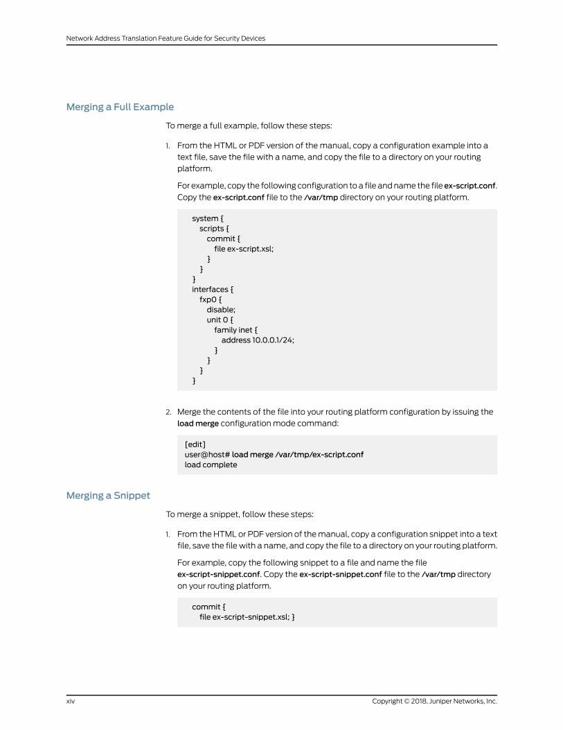
Merging a Full Example
Tomerge a full example, follow these steps:
1. From the HTML or PDF version of the manual, copy a configuration example into a
text file, save the file with a name, and copy the file to a directory on your routing
platform.
For example, copy the following configuration toa file andname the file ex-script.conf.
Copy the ex-script.conf file to the /var/tmp directory on your routing platform.
system {scripts {commit {file ex-script.xsl;
}}
}interfaces {fxp0 {disable;unit 0 {family inet {address 10.0.0.1/24;
}}
}}
2. Merge the contents of the file into your routing platform configuration by issuing the
loadmerge configuration mode command:
[edit]user@host# loadmerge /var/tmp/ex-script.confload complete
Merging a Snippet
Tomerge a snippet, follow these steps:
1. From the HTML or PDF version of themanual, copy a configuration snippet into a text
file, save the file with a name, and copy the file to a directory on your routing platform.
For example, copy the following snippet to a file and name the file
ex-script-snippet.conf. Copy the ex-script-snippet.conf file to the /var/tmp directory
on your routing platform.
commit {file ex-script-snippet.xsl; }
Copyright © 2018, Juniper Networks, Inc.xiv
Network Address Translation Feature Guide for Security Devices

2. Move to the hierarchy level that is relevant for this snippet by issuing the following
configuration mode command:
[edit]user@host# edit system scripts[edit system scripts]
3. Merge the contents of the file into your routing platform configuration by issuing the
loadmerge relative configuration mode command:
[edit system scripts]user@host# loadmerge relative /var/tmp/ex-script-snippet.confload complete
For more information about the load command, see CLI Explorer.
Documentation Conventions
Table 1 on page xv defines notice icons used in this guide.
Table 1: Notice Icons
DescriptionMeaningIcon
Indicates important features or instructions.Informational note
Indicates a situation that might result in loss of data or hardware damage.Caution
Alerts you to the risk of personal injury or death.Warning
Alerts you to the risk of personal injury from a laser.Laser warning
Indicates helpful information.Tip
Alerts you to a recommended use or implementation.Best practice
Table 2 on page xvi defines the text and syntax conventions used in this guide.
xvCopyright © 2018, Juniper Networks, Inc.
About the Documentation

Table 2: Text and Syntax Conventions
ExamplesDescriptionConvention
To enter configuration mode, type theconfigure command:
user@host> configure
Represents text that you type.Bold text like this
user@host> show chassis alarms
No alarms currently active
Represents output that appears on theterminal screen.
Fixed-width text like this
• A policy term is a named structurethat defines match conditions andactions.
• Junos OS CLI User Guide
• RFC 1997,BGPCommunities Attribute
• Introduces or emphasizes importantnew terms.
• Identifies guide names.
• Identifies RFC and Internet draft titles.
Italic text like this
Configure themachine’s domain name:
[edit]root@# set system domain-namedomain-name
Represents variables (options for whichyou substitute a value) in commands orconfiguration statements.
Italic text like this
• To configure a stub area, include thestub statement at the [edit protocolsospf area area-id] hierarchy level.
• Theconsoleport is labeledCONSOLE.
Represents names of configurationstatements, commands, files, anddirectories; configurationhierarchy levels;or labels on routing platformcomponents.
Text like this
stub <default-metricmetric>;Encloses optional keywords or variables.< > (angle brackets)
broadcast | multicast
(string1 | string2 | string3)
Indicates a choice between themutuallyexclusive keywords or variables on eitherside of the symbol. The set of choices isoften enclosed in parentheses for clarity.
| (pipe symbol)
rsvp { # Required for dynamicMPLS onlyIndicates a comment specified on thesame lineas theconfiguration statementto which it applies.
# (pound sign)
community namemembers [community-ids ]
Encloses a variable for which you cansubstitute one or more values.
[ ] (square brackets)
[edit]routing-options {static {route default {nexthop address;retain;
}}
}
Identifies a level in the configurationhierarchy.
Indention and braces ( { } )
Identifies a leaf statement at aconfiguration hierarchy level.
; (semicolon)
Copyright © 2018, Juniper Networks, Inc.xvi
Network Address Translation Feature Guide for Security Devices

Table 2: Text and Syntax Conventions (continued)
ExamplesDescriptionConvention
GUI Conventions
• In the Logical Interfaces box, selectAll Interfaces.
• To cancel the configuration, clickCancel.
Representsgraphicaluser interface(GUI)items you click or select.
Bold text like this
In the configuration editor hierarchy,select Protocols>Ospf.
Separates levels in a hierarchy of menuselections.
> (bold right angle bracket)
Documentation Feedback
We encourage you to provide feedback so that we can improve our documentation. You
can use either of the following methods:
• Online feedback system—Click TechLibrary Feedback, on the lower right of any page
on the Juniper Networks TechLibrary site, and do one of the following:
• Click the thumbs-up icon if the information on the page was helpful to you.
• Click the thumbs-down icon if the information on the page was not helpful to you
or if you have suggestions for improvement, and use the pop-up form to provide
feedback.
• E-mail—Sendyourcommentsto [email protected]. Includethedocument
or topic name, URL or page number, and software version (if applicable).
Requesting Technical Support
Technical product support is available through the JuniperNetworksTechnicalAssistance
Center (JTAC). If you are a customer with an active J-Care or Partner Support Service
support contract, or are covered under warranty, and need post-sales technical support,
you can access our tools and resources online or open a case with JTAC.
• JTAC policies—For a complete understanding of our JTAC procedures and policies,
review the JTAC User Guide located at
https://www.juniper.net/us/en/local/pdf/resource-guides/7100059-en.pdf.
• Product warranties—For product warranty information, visit
https://www.juniper.net/support/warranty/.
xviiCopyright © 2018, Juniper Networks, Inc.
About the Documentation

• JTAC hours of operation—The JTAC centers have resources available 24 hours a day,
7 days a week, 365 days a year.
Self-Help Online Tools and Resources
For quick and easy problem resolution, Juniper Networks has designed an online
self-service portal called the Customer Support Center (CSC) that provides youwith the
following features:
• Find CSC offerings: https://www.juniper.net/customers/support/
• Search for known bugs: https://prsearch.juniper.net/
• Find product documentation: https://www.juniper.net/documentation/
• Find solutions and answer questions using our Knowledge Base: https://kb.juniper.net/
• Download the latest versions of software and review release notes:
https://www.juniper.net/customers/csc/software/
• Search technical bulletins for relevant hardware and software notifications:
https://kb.juniper.net/InfoCenter/
• Join and participate in the Juniper Networks Community Forum:
https://www.juniper.net/company/communities/
• Open a case online in the CSC Case Management tool: https://www.juniper.net/cm/
Toverify serviceentitlementbyproduct serial number, useourSerialNumberEntitlement
(SNE) Tool: https://entitlementsearch.juniper.net/entitlementsearch/
Opening a Casewith JTAC
You can open a case with JTAC on theWeb or by telephone.
• Use the Case Management tool in the CSC at https://www.juniper.net/cm/.
• Call 1-888-314-JTAC (1-888-314-5822 toll-free in the USA, Canada, and Mexico).
For international or direct-dial options in countries without toll-free numbers, see
https://www.juniper.net/support/requesting-support.html.
Copyright © 2018, Juniper Networks, Inc.xviii
Network Address Translation Feature Guide for Security Devices
CHAPTER 1
Overview
• NAT Overview on page 19
• NAT Configuration Overview on page 24
NATOverview
Network Address Translation (NAT) is a mechanism to translate the IP address of a
computer or group of computers into a single public address when the packets are sent
out to the internet. By translating the IP address, only one IP address is publicized to the
outside network. Since only one IP address is visible to the outside world, NAT provides
additional security and it can have only one public address for the entire network instead
of having multiple IP addresses.
• Introduction to NAT on page 19
• Understanding NAT Rule Sets and Rules on page 20
Introduction to NAT
Network Address Translation (NAT) is a method for modifying or translating network
address information in packet headers. Either or both source and destination addresses
in a packet may be translated. NAT can include the translation of port numbers as well
as IP addresses.
NAT is described in RFC 1631 to solve IP (version 4) address depletion problems. Since
then, NAT has been found to be a useful tool for firewalls, traffic redirect, load sharing,
network migrations, and so on.
The following types of NAT are supported on Juniper Networks devices:
• Static NAT
• Destination NAT
• Source NAT
NOTE: SRX Series devices perform both policy lookup and service lookupbased on the translated destination port.
19Copyright © 2018, Juniper Networks, Inc.
You can use the NATWizard to perform basic NAT configuration. To performmore
advanced configuration, use the J-Web interface or the CLI.
See Also Source NAT on page 41•
• Destination NAT on page 105
• Static NAT on page 128
Understanding NAT Rule Sets and Rules
NATprocessingcenterson theevaluationofNAT rule setsand rules.A rule setdetermines
the overall direction of the traffic to be processed. For example, a rule set can select
traffic from a particular interface or to a specific zone. A rule set can contain multiple
rules. Once a rule set is found that matches specific traffic, each rule in the rule set is
evaluated for amatch. Each rule in the rule set further specifies the traffic to bematched
and the action to be taken when traffic matches the rule.
This topic includes the following sections:
• NAT Rule Sets on page 20
• NAT Rules on page 21
• Rule Processing on page 22
• NAT Rule Capacity on page 23
NAT Rule Sets
A rule set specifies a general set of matching conditions for traffic. For static NAT and
destination NAT, a rule set specifies one of the following:
• Source interface
• Source zone
• Source routing instance
For source NAT rule sets, you configure both source and destination conditions:
• Source interface, zone, or routing instance
• Destination interface, zone, or routing instance
It is possible for a packet to matchmore than one rule set; in this case, the rule set with
the more specific match is used. An interface match is consideredmore specific than a
zonematch, which is more specific than a routing instancematch. If a packet matches
both a destination NAT rule set that specifies a source zone and a destination NAT rule
set that specifies a source interface, the rule set that specifies the source interface is the
more specific match.
Source NAT rule set matching is more complex because you specify both source and
destination conditions in a sourceNAT rule set. In the casewhere a packetmatchesmore
than one source NAT rule set, the rule set chosen is based on the following
source/destination conditions (in order of priority):
Copyright © 2018, Juniper Networks, Inc.20
Network Address Translation Feature Guide for Security Devices
1. Source interface/destination interface
2. Source zone/destination interface
3. Source routing instance/destination interface
4. Source interface/destination zone
5. Source zone/destination zone
6. Source routing instance/destination zone
7. Source interface/destination routing instance
8. Source zone/destination routing instance
9. Source routing instance/destination routing instance
For example, you can configure rule set A, which specifies a source interface and a
destination zone, and rule setB,which specifies a source zoneandadestination interface.
If a packet matches both rule sets, rule set B is the more specific match.
NOTE: You cannot specify the same source and destination conditions forsource NAT rule sets.
NAT Rules
Once a rule set that matches the traffic has been found, each rule in the rule set is
evaluated in order for amatch. NAT rules canmatch on the following packet information:
• Source and destination address
• Source port (for source and static NAT only)
• Destination port
The first rule in the rule set that matches the traffic is used. If a packet matches a rule in
a rule set during session establishment, traffic is processed according to the action
specified by that rule.
You can use the show security nat source rule and show security nat destination rule and
the show security nat static rule commands to view the number of sessions for a specific
rule.
21Copyright © 2018, Juniper Networks, Inc.
Chapter 1: Overview

Rule Processing
The NAT type determines the order in which NAT rules are processed. During the first
packet processing for a flow, NAT rules are applied in the following order:
1. Static NAT rules
2. Destination NAT rules
3. Route lookup
4. Security policy lookup
5. Reverse mapping of static NAT rules
6. Source NAT rules
Figure 1 on page 22 illustrates the order for NAT rule processing.
Figure 1: NAT Rule Processing
Static NAT and destination NAT rules are processed before route and security policy
lookup. Static NAT rules take precedence over destination NAT rules. Reverse mapping
of staticNAT rules takesplaceafter routeandsecuritypolicy lookupand takesprecedence
over source NAT rules. Source NAT rules are processed after route and security policy
lookup and after reverse mapping of static NAT rules.
Theconfigurationof rulesand rule sets is basically the same for each typeofNAT—source,
destination, or static. But because both destination and static NAT are processed before
route lookup, you cannot specify the destination zone, interface or routing instance in
the rule set.
Copyright © 2018, Juniper Networks, Inc.22
Network Address Translation Feature Guide for Security Devices

NAT Rule Capacity
Table 3 on page 23 provides the NAT rule capacity requirements per device. Platform
support depends on the Junos OS release in your installation.
Table 3: Number of Rules on SRX Series Devices
SRX5400SRX5600SRX5800SRX4600
SRX4100SRX4200SRX1500
SRX340SRX345
SRX300SRX320SRX100
NAT RuleType
30,72051,20020,4808192204810241024SourceNAT rule
30,72051,20020,4808192204810241024DestinationNAT rule
30,72051,20020,4808192204810241024StaticNAT rule
The restriction on the number of rules per rule set is a device-wide limitation on how
many rules a device can support. This restriction is provided to help you better plan and
configure the NAT rules for the device.
For memory consumption, there is no guarantee to support these numbers (maximum
source rule or rule set +maximum destination rule or rule set +maximum static rule or
rule-set) at the same time for SRX3400, SRX3600, SRX5400, SRX5600, andSRX5800
devices.
Table 4 on page 23 provides the recommendedmaximum number of rules and rule sets
for SRX3400, SRX3600, SRX5400, SRX5600, andSRX5800devices. Platform support
depends on the Junos OS release in your installation.
Table 4: Number of Rules and Rule Sets
SRX5400SRX5600SRX5800SRX4600
SRX3400SRX3600Objects
30,72051,20020,480Total NAT rule sets persystem
30,72051,20020,480Total NAT rules perrule set
23Copyright © 2018, Juniper Networks, Inc.
Chapter 1: Overview
NAT Configuration Overview
This topic describes how to configure Network Address Translation (NAT) andmultiple
ISPs. Also, this topic helps to verify the NAT traffic by configuring the trace options and
monitoring NAT table.
• Configuring NAT Using the NATWizard on page 24
• Example: Configuring NAT for Multiple ISPs on page 24
• Configuring Proxy ARP for NAT (CLI Procedure) on page 37
• Configuring NAT trace options on page 37
• Monitoring NAT Incoming Table Information on page 39
• Monitoring Interface NAT Port Information on page 39
Configuring NATUsing the NATWizard
You can use the NATWizard to perform basic NAT configuration on SRX300, SRX320,
SRX340, SRX345, and SRX550Mdevices. To performmore advanced configuration, use
the J-Web interface or the CLI.
To configure NAT using the NATWizard:
1. Select Configure>Tasks>Configure NAT in the J-Web interface.
2. Click the Launch NATWizard button.
3. Follow the wizard prompts.
The upper-left area of thewizard page showswhere you are in the configuration process.
The lower-left area of the page shows field-sensitive help. When you click a link under
the Resources heading, the document opens in your browser. If the document opens in
a new tab, be sure to close only the tab (not the browser window) when you close the
document.
Example: Configuring NAT for Multiple ISPs
This example shows how to configure a Juniper Networks device for address translation
of multiple ISPs.
• Requirements on page 25
• Overview on page 25
• Configuration on page 25
• Verification on page 36
Copyright © 2018, Juniper Networks, Inc.24
Network Address Translation Feature Guide for Security Devices

Requirements
Before you begin:
1. Configure network interfaces on the device. See Interfaces Feature Guide for Security
Devices.
2. Create security zonesandassign interfaces to them.SeeUnderstandingSecurity Zones.
Overview
In this example, you can configure an SRX Series Services Gateway by connecting the
LAN to the Internet by using NAT feature through two ISP connections. In this
configuration, trust is the security zone for the private address space and the two untrust
security zones for the public address space are used to connect from LAN to the two
ISPs and vice versa. The example is a combination of source NAT rules to connect to
Internet from the LAN, and destination and static NAT rules to connect to the LAN from
Internet.
Configuration
Configuring NAT for Multiple ISPs
CLI QuickConfiguration
To quickly configure this example, copy the following commands, paste them into a text
file, remove any line breaks, change any details necessary to match your network
configuration, copy and paste the commands into the CLI at the [edit] hierarchy level,
and then enter commit from configuration mode.
set routing-instances isp1 instance-type virtual-routerset routing-instances isp1 interface ge-0/0/2.0set routing-instances isp1 routing-options static route 10.0.0.0/8 next-table inet.0set routing-instances isp1 routing-options static route 0.0.0.0/0 next-hop 192.0.2.20set routing-instances isp2 instance-type virtual-routerset routing-instances isp2 interface ge-0/0/3.0set routing-instances isp2 routing-options static route 10.0.0.0/8 next-table inet.0set routing-instances isp2 routing-options static route0.0.0.0/0next-hop 198.51.100.251set routing-options interface-routes rib-group inet ispset routing-options static route 10.0.0.0/8 next-hop 10.0.21.254set routing-options rib-groups isp import-rib inet.0set routing-options rib-groups isp import-rib isp1.inet.0set routing-options rib-groups isp import-rib isp2.inet.0set security policies from-zone trust to-zone untrust1 policy tr-untr1-pol matchsource-address any
set security policies from-zone trust to-zone untrust1 policy tr-untr1-pol matchdestination-address any
setsecuritypolicies from-zonetrust to-zoneuntrust1policy tr-untr1-polmatchapplicationany
set security policies from-zone trust to-zone untrust1 policy tr-untr1-pol then permitset security policies from-zone trust to-zone untrust2 policy tr-untr2-pol matchsource-address any
set security policies from-zone trust to-zone untrust2 policy tr-untr2-pol matchdestination-address any
25Copyright © 2018, Juniper Networks, Inc.
Chapter 1: Overview

setsecuritypolicies from-zonetrust to-zoneuntrust2policy tr-untr2-polmatchapplicationany
set security policies from-zone trust to-zone untrust2 policy tr-untr2-pol then permitset security policies from-zone untrust1 to-zone untrust2 policy untr1-untr2-pol matchsource-address any
set security policies from-zone untrust1 to-zone untrust2 policy untr1-untr2-pol matchdestination-address any
set security policies from-zone untrust1 to-zone untrust2 policy untr1-untr2-pol matchapplication any
setsecuritypolicies from-zoneuntrust1 to-zoneuntrust2policyuntr1-untr2-pol then rejectset security policies from-zone untrust2 to-zone untrust1 policy untr2-untr1-pol matchsource-address any
set security policies from-zone untrust2 to-zone untrust1 policy untr2-untr1-pol matchdestination-address any
set security policies from-zone untrust2 to-zone untrust1 policy untr2-untr1-pol matchapplication any
setsecuritypolicies from-zoneuntrust2 to-zoneuntrust1policyuntr2-untr1-pol then rejectset security policies from-zone untrust1 to-zone trust policy untr1-tr-pol matchsource-address any
set security policies from-zone untrust1 to-zone trust policy untr1-tr-pol matchdestination-address ftp-ser
set security policies from-zone untrust1 to-zone trust policy untr1-tr-pol matchdestination-address telnet-ser
setsecuritypolicies from-zoneuntrust1 to-zonetrustpolicyuntr1-tr-polmatchapplicationjunos-ftp
setsecuritypolicies from-zoneuntrust1 to-zonetrustpolicyuntr1-tr-polmatchapplicationjunos-telnet
set security policies from-zone untrust1 to-zone trust policy untr1-tr-pol then permitset security policies from-zone untrust2 to-zone trust policy untr2-tr-pol matchsource-address any
set security policies from-zone untrust2 to-zone trust policy untr2-tr-pol matchdestination-address 10.171.9.23/32
set security policies from-zone untrust2 to-zone trust policy untr2-tr-pol matchdestination-address http-ser
set security policies from-zone untrust2 to-zone trust policy untr2-tr-pol matchdestination-address 10.103.12.0/24
setsecuritypolicies from-zoneuntrust2to-zonetrustpolicyuntr2-tr-polmatchapplicationjunos-http
setsecuritypolicies from-zoneuntrust2to-zonetrustpolicyuntr2-tr-polmatchapplicationjunos-icmp-all
setsecuritypolicies from-zoneuntrust2to-zonetrustpolicyuntr2-tr-polmatchapplicationjunos-dhcp-server
set security policies from-zone untrust2 to-zone trust policy untr2-tr-pol then permitset security nat source pool pool_1 address 192.0.2.40/32 to 192.0.2.190/32set security nat source pool pool_2 address 192.0.2.250/32set security nat source pool pool_3 address 198.51.100.20/32 to 198.51.100.30/32set security nat source address-persistentset security nat source pool-utilization-alarm raise-threshold 90set security nat source pool-utilization-alarm clear-threshold 80set security nat source rule-set SR_SET_1 from zone trustset security nat source rule-set SR_SET_1 to zone untrust1set security nat source rule-set SR_SET_1 rule rule1 match source-address 10.11.0.0/16set security nat source rule-set SR_SET_1 rule rule1 match source-address 10.147.0.0/16set security nat source rule-set SR_SET_1 rule rule1match destination-address 0.0.0.0/0set security nat source rule-set SR_SET_1 rule rule1 then source-nat pool pool_1
Copyright © 2018, Juniper Networks, Inc.26
Network Address Translation Feature Guide for Security Devices

set security nat source rule-set SR_SET_1 rule rule2match source-address 10.148.1.0/27set security nat source rule-set SR_SET_1 rule rule2matchdestination-address0.0.0.0/0set security nat source rule-set SR_SET_1 rule rule2 then source-nat interfaceset security nat source rule-set SR_SET_2 from zone trustset security nat source rule-set SR_SET_2 to zone untrust2set security nat source rule-setSR_SET_2 rule rule3match source-address 10.140.21.0/27set security nat source rule-set SR_SET_2 rule rule3 then source-nat pool pool_3setsecuritynatsource rule-setSR_SET_2 rule rule4matchsource-address 10.150.45.0/24set security nat source rule-set SR_SET_2 rule rule4 then source-nat offset security nat destination pool dppol_1 address 10.101.1.10/32set security nat destination pool dppol_1 address port 21set security nat destination pool dppol_2 address 10.101.1.11/32set security nat destination pool dppol_2 address port 2101set security nat destination pool dppol_3 address 10.103.12.251/32set security nat destination pool dppol_3 address port 23set security nat destination pool dppol_4 address 10.103.12.241/32set security nat destination pool dppol_4 address port 23set security nat destination pool dppol_5 address 10.103.1.11/32set security nat destination pool dppol_5 address port 22set security nat destination rule-set DR_SET1 from routing-instance isp1set security nat destination rule-set DR_SET1 rule rule1 match destination-address192.168.0.10/32
set security nat destination rule-set DR_SET1 rule rule1 match destination-port 7230set security nat destination rule-set DR_SET1 rule rule1 then destination-nat pool dppol_1set security nat destination rule-set DR_SET1 rule rule2match destination-address192.169.1.0/24
set securitynatdestination rule-setDR_SET1 rule rule2 thendestination-natpooldppol_2set security nat destination rule-set DR_SET2 from routing-instance isp2set security nat destination rule-set DR_SET2 rule rule3match destination-address192.168.2.2/32
set security nat destination rule-set DR_SET2 rule rule3match destination-port 7351set securitynatdestination rule-setDR_SET2 rule rule3 thendestination-natpooldppol_3set security nat destination rule-set DR_SET2 rule rule4match destination-address192.168.4.171/32
set security nat destination rule-set DR_SET2 rule rule4match destination-port 3451setsecuritynatdestination rule-setDR_SET2 rule rule4 thendestination-natpooldppol_4set security nat static rule-set ST_SET1 from zone trustset security nat static rule-setST_SET1 rule rule1matchdestination-address 10.0.10.0/24set security nat static rule-set ST_SET1 rule rule1 then static-nat prefix 192.168.5.0/24set security nat static rule-set ST_SET2 from routing-instance isp1set security nat static rule-set ST_SET2 rule rule2match destination-address192.168.6.0/24
set security nat static rule-set ST_SET2 rule rule2 then static-nat prefix 10.107.30.0/24set security nat static rule-set ST_SET2 rule rule3match destination-address192.168.0.10/32
set security nat static rule-set ST_SET2 rule rule3 then static-nat prefix 10.171.9.23/32
Step-by-StepProcedure
The following example requires you to navigate various levels in the configuration
hierarchy. For instructions on how to do that, see Using the CLI Editor in Configuration
Mode in the Junos OS CLI User Guide.
1. Configure routing instances.
27Copyright © 2018, Juniper Networks, Inc.
Chapter 1: Overview

[edit ]user@host# set routing-instances isp1 instance-type virtual-routeruser@host# set routing-instances isp1 interface ge-0/0/2.0user@host# set routing-instances isp1 routing-options static route 10.0.0.0/8next-table inet.0
user@host# set routing-instances isp1 routing-options static route 0.0.0.0/0next-hop 192.0.2.20
user@host# set routing-instances isp2 instance-type virtual-routeruser@host# set routing-instances isp2 interface ge-0/0/3.0user@host# set routing-instances isp2 routing-options static route 10.0.0.0/8next-table inet.0
user@host# set routing-instances isp2 routing-options static route 0.0.0.0/0next-hop 198.51.100.251
2. Configure rib groups and routing options.
[edit ]user@host# set routing-options interface-routes rib-group inet ispuser@host# set routing-options static route 10.0.0.0/8 next-hop 10.0.21.254user@host# set routing-options rib-groups isp import-rib inet.0user@host# set routing-options rib-groups isp import-rib isp1.inet.0user@host# set routing-options rib-groups isp import-rib isp2.inet.0
3. Configure security policies.
[edit security policies]user@host# set from-zone trust to-zone untrust1 policy tr-untr1-pol matchsource-address any
user@host# set from-zone trust to-zone untrust1 policy tr-untr1-pol matchdestination-address any
user@host# set from-zone trust to-zone untrust1 policy tr-untr1-pol matchapplication any
user@host# set from-zone trust to-zone untrust1 policy tr-untr1-pol then permituser@host# set from-zone trust to-zone untrust2 policy tr-untr2-pol matchsource-address any
user@host# set from-zone trust to-zone untrust2 policy tr-untr2-pol matchdestination-address any
user@host# set from-zone trust to-zone untrust2 policy tr-untr2-pol matchapplication any
user@host# set from-zone trust to-zone untrust2 policy tr-untr2-pol then permituser@host# set from-zone untrust1 to-zone untrust2 policy untr1-untr2-pol matchsource-address any
user@host# set from-zone untrust1 to-zone untrust2 policy untr1-untr2-pol matchdestination-addressanyfrom-zoneuntrust1 to-zoneuntrust2policyuntr1-untr2-polmatch destination-address any
user@host# set from-zone untrust1 to-zone untrust2 policy untr1-untr2-pol matchapplication any
user@host# set from-zone untrust1 to-zone untrust2 policy untr1-untr2-pol thenreject
user@host# set from-zone untrust2 to-zone untrust1 policy untr2-untr1-pol matchsource-address any
Copyright © 2018, Juniper Networks, Inc.28
Network Address Translation Feature Guide for Security Devices

user@host# set from-zone untrust2 to-zone untrust1 policy untr2-untr1-pol matchdestination-address any
user@host# set from-zone untrust2 to-zone untrust1 policy untr2-untr1-pol matchapplication any
user@host# set from-zone untrust2 to-zone untrust1 policy untr2-untr1-pol thenreject
user@host# set from-zone untrust1 to-zone trust policy untr1-tr-pol matchsource-address any
user@host# set from-zone untrust1 to-zone trust policy untr1-tr-pol matchdestination-address ftp-ser
user@host# set from-zone untrust1 to-zone trust policy untr1-tr-pol matchdestination-address telnet-ser
user@host# set from-zone untrust1 to-zone trust policy untr1-tr-pol matchapplication junos-ftp
user@host# set from-zone untrust1 to-zone trust policy untr1-tr-pol matchapplication junos-telnet
user@host# set from-zone untrust1 to-zone trust policy untr1-tr-pol then permituser@host# set from-zone untrust2 to-zone trust policy untr2-tr-pol matchsource-address any
user@host# set from-zone untrust2 to-zone trust policy untr2-tr-pol matchdestination-address 10.171.9.23/32
user@host# set from-zone untrust2 to-zone trust policy untr2-tr-pol matchdestination-address http-ser
user@host# set from-zone untrust2 to-zone trust policy untr2-tr-pol matchdestination-address 10.103.12.0/24
user@host# set from-zone untrust2 to-zone trust policy untr2-tr-pol matchapplication junos-http
user@host# set from-zone untrust2 to-zone trust policy untr2-tr-pol matchapplication junos-icmp-all
user@host# set from-zone untrust2 to-zone trust policy untr2-tr-pol matchapplication junos-dhcp-server
user@host# set from-zone untrust2 to-zone trust policy untr2-tr-pol then permit
4. Configure source NAT pools and rules.
[edit security nat]user@host# set source pool pool_1 address 192.0.2.40/32 to 192.0.2.190/32user@host# set source pool pool_2 address 192.0.2.250/32user@host# set source pool pool_3 address 198.51.100.20/32 to 198.51.100.30/32user@host# set source address-persistentuser@host# set source pool-utilization-alarm raise-threshold 90user@host# set source pool-utilization-alarm clear-threshold 80user@host# set source rule-set SR_SET_1 from zone trustuser@host# set source rule-set SR_SET_1 to zone untrust1user@host#setsourcerule-setSR_SET_1 rule rule1matchsource-address10.11.0.0/16user@host# set source rule-set SR_SET_1 rule rule1 match source-address10.147.0.0/16
user@host# set source rule-set SR_SET_1 rule rule1 match destination-address0.0.0.0/0
user@host# set source rule-set SR_SET_1 rule rule1 then source-nat pool pool_1user@host# set source rule-set SR_SET_1 rule rule2match source-address10.148.1.0/27
user@host# set source rule-set SR_SET_1 rule rule2match destination-address0.0.0.0/0
29Copyright © 2018, Juniper Networks, Inc.
Chapter 1: Overview

user@host# set source rule-set SR_SET_1 rule rule2 then source-nat interfaceuser@host# set source rule-set SR_SET_2 from zone trustuser@host# set source rule-set SR_SET_2 to zone untrust2user@host# set source rule-set SR_SET_2 rule rule3match source-address10.140.21.0/27
user@host# set source rule-set SR_SET_2 rule rule3 then source-nat pool pool_3user@host# set source rule-set SR_SET_2 rule rule4match source-address10.150.45.0/24
user@host# set source rule-set SR_SET_2 rule rule4 then source-nat off
5. Configure destination NAT pools and rules.
[edit security nat]user@host#set destination pool dppol_1 address 10.101.1.10/32user@host#set destination pool dppol_1 address port 21user@host#set destination pool dppol_2 address 10.101.1.11/32user@host#set destination pool dppol_2 address port 2101user@host#set destination pool dppol_3 address 10.103.12.251/32user@host#set destination pool dppol_3 address port 23user@host#set destination pool dppol_4 address 10.103.12.241/32user@host#set destination pool dppol_4 address port 23user@host#set destination pool dppol_5 address 10.103.1.11/32user@host#set destination pool dppol_5 address port 22user@host#set destination rule-set DR_SET1 from routing-instance isp1user@host#set destination rule-set DR_SET1 rule rule1 match destination-address192.168.0.10/32
user@host#setdestinationrule-setDR_SET1 rule rule1matchdestination-port7230user@host#set destination rule-set DR_SET1 rule rule1 then destination-nat pooldppol_1
user@host#set destination rule-set DR_SET1 rule rule2match destination-address192.169.1.0/24
user@host#set destination rule-set DR_SET1 rule rule2 then destination-nat pooldppol_2
user@host#set destination rule-set DR_SET2 from routing-instance isp2user@host#set destination rule-setDR_SET2 rule rule3matchdestination-address192.168.2.2/32
user@host#setdestination rule-setDR_SET2rule rule3matchdestination-port7351user@host#set destination rule-set DR_SET2 rule rule3 then destination-nat pooldppol_3
user@host#set destination rule-setDR_SET2 rule rule4matchdestination-address192.168.4.171/32
user@host#set destination rule-set DR_SET2 rule rule4match destination-port3451
user@host#set destination rule-set DR_SET2 rule rule4 then destination-nat pooldppol_4
6. Configure static NAT rules.
[edit security nat]user@host#set static rule-set ST_SET1 from zone trustuser@host#set static rule-set ST_SET1 rule rule1 match destination-address10.0.10.0/24
Copyright © 2018, Juniper Networks, Inc.30
Network Address Translation Feature Guide for Security Devices
user@host#setstatic rule-setST_SET1 rule rule1 thenstatic-natprefix 192.168.5.0/24user@host#set static rule-set ST_SET2 from routing-instance isp1user@host#set static rule-set ST_SET2 rule rule2match destination-address192.168.6.0/24
user@host#set static rule-set ST_SET2 rule rule2 then static-nat prefix10.107.30.0/24
user@host#set static rule-set ST_SET2 rule rule3match destination-address192.168.7.2/32
user@host#setstatic rule-setST_SET2rule rule3thenstatic-natprefix 10.171.9.23/32
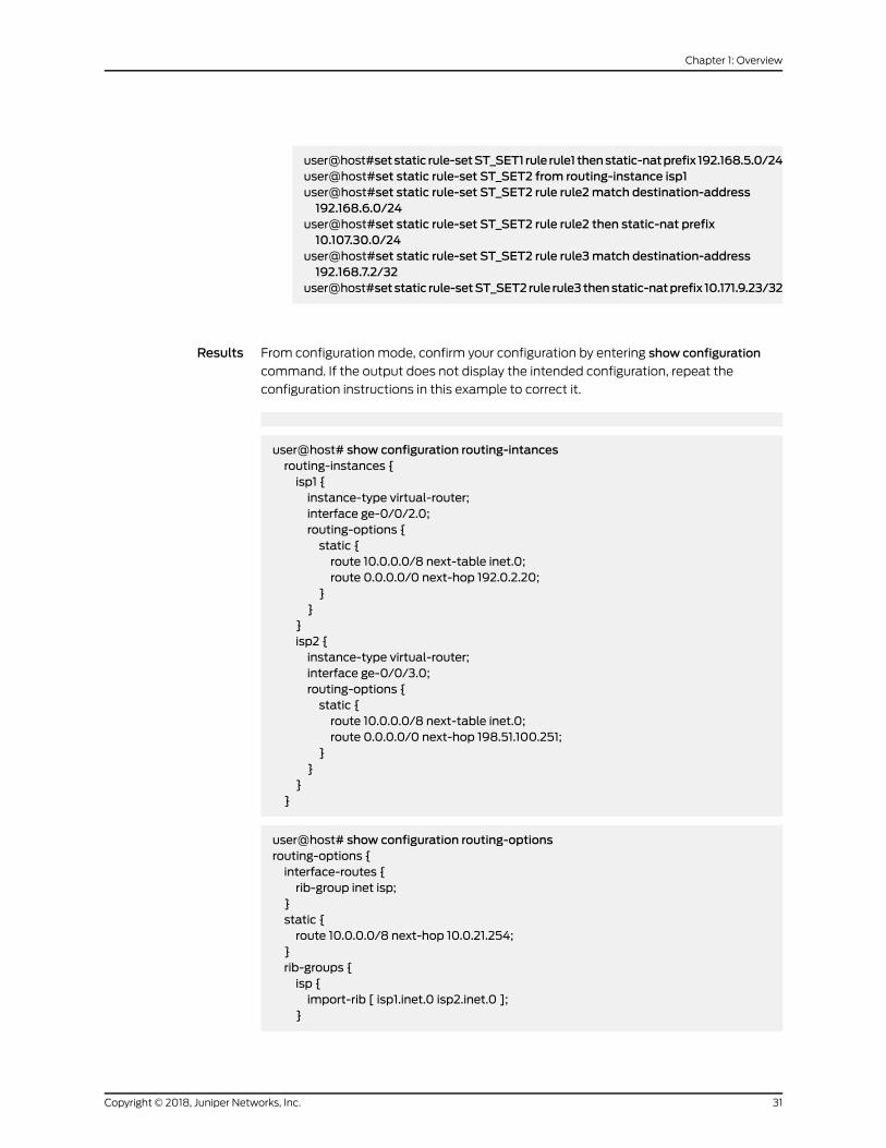
Results From configuration mode, confirm your configuration by entering show configuration
command. If the output does not display the intended configuration, repeat the
configuration instructions in this example to correct it.
user@host# show configuration routing-intancesrouting-instances {isp1 {instance-type virtual-router;interface ge-0/0/2.0;routing-options {static {route 10.0.0.0/8 next-table inet.0;route 0.0.0.0/0 next-hop 192.0.2.20;
}}
}isp2 {instance-type virtual-router;interface ge-0/0/3.0;routing-options {static {route 10.0.0.0/8 next-table inet.0;route 0.0.0.0/0 next-hop 198.51.100.251;
}}
}}
user@host# show configuration routing-optionsrouting-options {interface-routes {rib-group inet isp;
}static {route 10.0.0.0/8 next-hop 10.0.21.254;
}rib-groups {isp {import-rib [ isp1.inet.0 isp2.inet.0 ];
}
31Copyright © 2018, Juniper Networks, Inc.
Chapter 1: Overview

}}
user@host# show configuration policiespolicies {from-zone trust to-zone untrust1 {policy tr-untr1-pol {match {source-address any;destination-address any;application any;
}then {permit;
}}
}from-zone trust to-zone untrust2 {policy tr-untr2-pol {match {source-address any;destination-address any;application any;
}then {permit;
}}
}from-zone untrust1 to-zone untrust2 {policy untr1-untr2-pol {match {source-address any;destination-address any;application any;
}then {reject;
}}
}from-zone untrust2 to-zone untrust1 {policy untr2-untr1-pol {match {source-address any;destination-address any;application any;
}then {reject;
}}
}from-zone untrust1 to-zone trust {
Copyright © 2018, Juniper Networks, Inc.32
Network Address Translation Feature Guide for Security Devices

policy untr1-tr-pol {match {source-address any;destination-address [ ftp-ser telnet-ser ];application [ junos-ftp junos-telnet ];
}then {permit;
}}
}from-zone untrust2 to-zone trust {policy untr2-tr-pol {match {source-address any;destination-address [ 10.171.9.23/32 http-ser 10.103.12.0/24 ];application [ junos-http junos-icmp-all junos-dhcp-server ];
}then {permit;
}}
}}
user@host# show configuration security natsecurity {nat {source {pool pool_1 {address {192.0.2.40/32 to 192.0.2.190/32;
}}pool pool_2 {address {192.0.2.250/32;
}}pool pool_3 {address {198.51.100.20/32 to 198.51.100.30/32;
}}address-persistent;pool-utilization-alarm raise-threshold 90 clear-threshold 80;rule-set SR_SET_1 {from zone trust;to zone untrust1;rule rule1 {match {source-address [ 10.11.0.0/16 10.147.0.0/16 ];destination-address 0.0.0.0/0;
}
33Copyright © 2018, Juniper Networks, Inc.
Chapter 1: Overview

then {source-nat {pool {pool_1;
}}
}}rule rule2 {match {source-address 10.148.1.0/27;destination-address 0.0.0.0/0;
}then {source-nat {interface;
}}
}}rule-set SR_SET_2 {from zone trust;to zone untrust2;rule rule3 {match {source-address 10.140.21.0/27;
}then {source-nat {pool {pool_3;
}}
}}rule rule4 {match {source-address 10.150.45.0/24;
}then {source-nat {off;
}}
}}
}
user@host# show configuration security natdestination {pool dppol_1 {address 10.101.1.10/32 port 21;
}pool dppol_2 {
Copyright © 2018, Juniper Networks, Inc.34
Network Address Translation Feature Guide for Security Devices
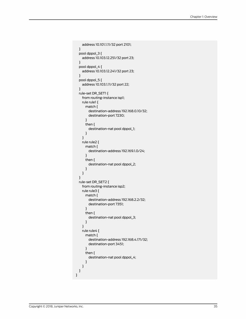
address 10.101.1.11/32 port 2101;}pool dppol_3 {address 10.103.12.251/32 port 23;
}pool dppol_4 {address 10.103.12.241/32 port 23;
}pool dppol_5 {address 10.103.1.11/32 port 22;
}rule-set DR_SET1 {from routing-instance isp1;rule rule1 {match {destination-address 192.168.0.10/32;destination-port 7230;
}then {destination-nat pool dppol_1;
}}rule rule2 {match {destination-address 192.169.1.0/24;
}then {destination-nat pool dppol_2;
}}
}rule-set DR_SET2 {from routing-instance isp2;rule rule3 {match {destination-address 192.168.2.2/32;destination-port 7351;
}then {destination-nat pool dppol_3;
}}rule rule4 {match {destination-address 192.168.4.171/32;destination-port 3451;
}then {destination-nat pool dppol_4;
}}
}}
35Copyright © 2018, Juniper Networks, Inc.
Chapter 1: Overview

user@host# show configuration static natstatic {rule-set ST_SET1 {from zone trust;rule rule1 {match {destination-address 10.0.10.0/24;
}then {static-nat prefix 192.168.5.0/24;
}}
}rule-set ST_SET2 {from routing-instance isp1;rule rule2 {match {destination-address 192.168.6.0/24;
}then {static-nat prefix 10.107.30.0/24;
}}rule rule3 {match {destination-address 192.168.7.2/32;
}then {static-nat prefix 10.171.9.23/32;
}}
}}
}
If you are done configuring the device, enter commit from configuration mode.
Verification
Verifying Interfaces
Purpose Verify that the interfaces are configured correctly.
Action From operational mode, enter the following commands:
• show interfaces
• show zones
• show routing-instances
• show routing-options
• show policies
Copyright © 2018, Juniper Networks, Inc.36
Network Address Translation Feature Guide for Security Devices

• show source nat
• show destination nat
• show static nat
Configuring Proxy ARP for NAT (CLI Procedure)
You use NAT proxy ARP functionality to configure proxy ARP entries for IP addresses
that require either source or destination NAT and that are in the same subnet as the
ingress interface.
NOTE: On SRX Series devices, youmust explicitly configure NAT proxy ARP.
When configuring NAT proxy ARP, youmust specify the logical interface on which to
configure proxy ARP. Then you enter an address or address range.
The device performs proxy ARP for the following conditions:
• Whenaddresses defined in the static NATand sourceNATpool are in the same subnet
as that of the ingress interface
• When addresses in the original destination address entry in the destination NAT rules
are in the same subnet as that of the ingress interface
user@host# set security nat proxy-arp interface fe-0/0/0.0 address 10.1.1.10 to 10.1.1.20
Configuring NAT trace options
Purpose The NAT trace options hierarchy configures trace file and flags for verification purposes.
SRXSeries devices have twomain components: the Routing Engine (RE) and the Packet
Forwarding Engine (PFE). The PFE is divided into the ukernel portion and the real-time
portion.
When a NAT configuration is committed, the configuration is first checked and validated
on the RE. After validation, the configuration is pushed to the PFE. The configuration is
installed on the ukernel PFE, then action is taken on each packet thatmatches NAT rules
on the real-time PFE.
For verification, you can turn on flags individually to debug NAT functionality on the RE,
ukernel PFE, or real-time PFE:
• The nat-re flag records the trace of the NAT configuration validation on the RE and the
configuration push to the PFE.
• The nat-pfe flag records the trace of the NAT configuration installation on the ukernel
PFE.
• The nat-rt flag records the trace of the NAT rule match, and subsequent action on the
real-time PFE.
37Copyright © 2018, Juniper Networks, Inc.
Chapter 1: Overview

The trace data is written to /var/log/security-trace by default, and can be viewed using
the command show log security-trace.
NOTE: If session logging has been enabled in the policy configurations onthe device, the session logswill include specific NATdetails for each session.SeeMonitoring Policy Statistics for information on how to enable sessionloggingand InformationProvided inSessionLogEntries forSRXSeriesServicesGateways for a description of information provided in session logs.
Action To verify that NAT configurations are correctly updated to the device upon commit, and
that the NAT rule match and subsequent actions are correct, use the security nat
traceoptions statement.
user@host# set security nat traceoptions flag alluser@host# set security nat traceoptions flag destination-nat-pfeuser@host# set security nat traceoptions flag destination-nat-reuser@host# set security nat traceoptions flag destination-nat-rtiuser@host# set security nat traceoptions flag source-nat-pfeuser@host# set security nat traceoptions flag source-nat-reuser@host# set security nat traceoptions flag source-nat-rtuser@host# set security nat traceoptions flag static-nat-pfeuser@host# set security nat traceoptions flag static-nat-reuser@host# set security nat traceoptions flag static-nat-rt
To verify that NAT translations are being applied to the traffic, and to view individual
traffic flow processing with NAT translations, use both the security nat traceoptions
command and the security flow traceoptions command together. The commands are
used together because the NAT trace, configured using the security nat traceoptions
command, is not recorded unless the flow traceoptions command is also configured.
To filter a specific flow, you can define a packet filter and use it as a traceoption :
user@host# set security flow traceoptions packet-filter packet-filteruser@host# set security flow traceoptions packet-filter packet-filter apply-groupsuser@host#setsecurity flowtraceoptionspacket-filterpacket-filterapply-groups-exceptuser@host# set security flow traceoptions packet-filter packet-filter destination-portuser@host# set security flow traceoptions packet-filter packet-filter destination-prefixuser@host# set security flow traceoptions packet-filter packet-filter interfaceuser@host# set security flow traceoptions packet-filter packet-filter protocoluser@host# set security flow traceoptions packet-filter packet-filter source-portuser@host# set security flow traceoptions packet-filter packet-filter source-prefix
To verify NAT traffic and to enable all traffic trace in data plane, use the traceoptions set
security flow traceoptions flag basic-datapath command, as shown in the following
example using a simple packet filter:
user@host# set security flow traceoptions file filenameuser@host# set security flow traceoptions flag basic-datapath
Copyright © 2018, Juniper Networks, Inc.38
Network Address Translation Feature Guide for Security Devices
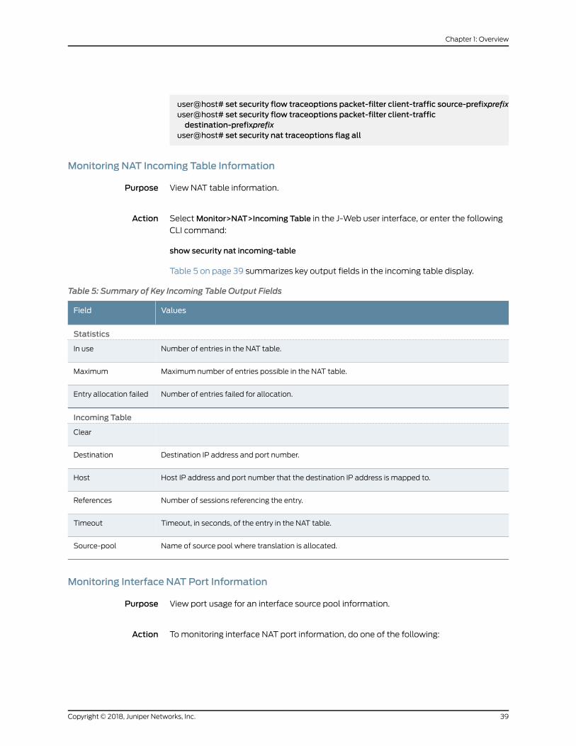
user@host# set security flow traceoptions packet-filter client-traffic source-prefixprefixuser@host# set security flow traceoptions packet-filter client-trafficdestination-prefixprefix
user@host# set security nat traceoptions flag all
Monitoring NAT Incoming Table Information
Purpose View NAT table information.
Action SelectMonitor>NAT>Incoming Table in the J-Web user interface, or enter the following
CLI command:
show security nat incoming-table
Table 5 on page 39 summarizes key output fields in the incoming table display.
Table 5: Summary of Key Incoming Table Output Fields
ValuesField
Statistics
Number of entries in the NAT table.In use
Maximum number of entries possible in the NAT table.Maximum
Number of entries failed for allocation.Entry allocation failed
Incoming Table
Clear
Destination IP address and port number.Destination
Host IP address and port number that the destination IP address is mapped to.Host
Number of sessions referencing the entry.References
Timeout, in seconds, of the entry in the NAT table.Timeout
Name of source pool where translation is allocated.Source-pool
Monitoring Interface NAT Port Information
Purpose View port usage for an interface source pool information.
Action Tomonitoring interface NAT port information, do one of the following:
39Copyright © 2018, Juniper Networks, Inc.
Chapter 1: Overview

• If you are using SRX5400, SRX5600, or SRX5800 platforms, select
Monitor>Firewall/NAT>Interface NAT in the J-Web user interface or enter the CLI
command show security nat interface-nat-ports.
• SelectMonitor>NAT>Interface NAT Ports in the J-Web user interface.
Table 6 on page 40 summarizes key output fields in the interface NAT display.
Table 6: Summary of Key Interface NATOutput Fields
Additional InformationValuesField
Interface NAT Summary Table
–Port pool index.Pool Index
–Total number of ports in a port pool.Total Ports
–Number of ports allocated one at a time that are in use.SinglePortsAllocated
–Number of ports allocated one at a time that are freefor use.
SinglePortsAvailable
–Number of ports allocated twoat a time that are in use.Twin PortsAllocated
–Number of ports allocated two at a time that are freefor use.
Twin PortsAvailable
Copyright © 2018, Juniper Networks, Inc.40
Network Address Translation Feature Guide for Security Devices
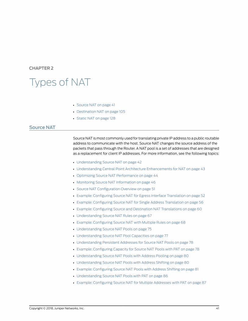
CHAPTER 2
Types of NAT
• Source NAT on page 41
• Destination NAT on page 105
• Static NAT on page 128
Source NAT
SourceNAT ismost commonly used for translatingprivate IP address to apublic routable
address to communicate with the host. Source NAT changes the source address of the
packets that pass through the Router. A NAT pool is a set of addresses that are designed
as a replacement for client IP addresses. For more information, see the following topics:
• Understanding Source NAT on page 42
• Understanding Central Point Architecture Enhancements for NAT on page 43
• Optimizing Source NAT Performance on page 44
• Monitoring Source NAT Information on page 46
• Source NAT Configuration Overview on page 51
• Example: Configuring Source NAT for Egress Interface Translation on page 52
• Example: Configuring Source NAT for Single Address Translation on page 56
• Example: Configuring Source and Destination NAT Translations on page 60
• Understanding Source NAT Rules on page 67
• Example: Configuring Source NATwith Multiple Rules on page 68
• Understanding Source NAT Pools on page 75
• Understanding Source NAT Pool Capacities on page 77
• Understanding Persistent Addresses for Source NAT Pools on page 78
• Example: Configuring Capacity for Source NAT Pools with PAT on page 78
• Understanding Source NAT Pools with Address Pooling on page 80
• Understanding Source NAT Pools with Address Shifting on page 80
• Example: Configuring Source NAT Pools with Address Shifting on page 81
• Understanding Source NAT Pools with PAT on page 86
• Example: Configuring Source NAT for Multiple Addresses with PAT on page 87
41Copyright © 2018, Juniper Networks, Inc.

• Understanding Source NAT PoolsWithout PAT on page 92
• Example: ConfiguringaSingle IPAddress in aSourceNATPoolWithoutPATonpage92
• Example:ConfiguringMultipleAddresses inaSourceNATPoolWithoutPATonpage96
• Understanding Shared Addresses in Source NAT Pools without PAT on page 101
• Understanding NAT Session Persistence on page 101
• Configuring the NAT Session Hold Timeout and NAT Session Persistence
Scan on page 102
• UnderstandingNATConfigurationCheckonEgress InterfacesafterRerouteonpage 103
Understanding Source NAT
Source NAT is the translation of the source IP address of a packet leaving the Juniper
Networks device. Source NAT is used to allow hosts with private IP addresses to access
a public network.
SourceNATallowsconnections tobe initiatedonly for outgoingnetwork connections—for
example, fromaprivatenetwork to the Internet. SourceNAT is commonlyused toperform
the following translations:
• Translate a single IP address to another address (for example, to provide a single
device in a private network with access to the Internet).
• Translate a contiguous block of addresses to another block of addresses of the same
size.
• Translate a contiguous block of addresses to another block of addresses of smaller
size.
• Translate a contiguous block of addresses to a single IP address or a smaller block of
addresses using port translation.
• Translate a contiguous block of addresses to the address of the egress interface.
Translation to the address of the egress interface does not require an address pool; all
other source NAT translations require configuration of an address pool. One-to-one and
many-to-many translations for address blocks of the same size do not require port
translation because there is an available address in the pool for every address thatwould
be translated.
If the size of the address pool is smaller than the number of addresses that would be
translated, either the total number of concurrent addresses that can be translated is
limited by the size of the address pool or port translation must be used. For example, if
a block of 253 addresses is translated to an address pool of 10 addresses, a maximum
of 10 devices can be connected concurrently unless port translation is used.
The following types of source NAT are supported:
• Translation of the original source IP address to the egress interface’s IP address (also
called interface NAT). Port address translation is always performed.
• Translation of the original source IP address to an IP address from a user-defined
address pool without port address translation. The association between the original
Copyright © 2018, Juniper Networks, Inc.42
Network Address Translation Feature Guide for Security Devices

source IP address to the translated source IP address is dynamic. However, once there
is an association, the same association is used for the same original source IP address
for new traffic that matches the same NAT rule.
• Translation of the original source IP address to an IP address from a user-defined
addresspoolwithport address translation. Theassociationbetween theoriginal source
IP address to the translated source IP address is dynamic. Even if an association exists,
the same original source IP address may be translated to a different address for new
traffic that matches the same NAT rule.
• Translation of the original source IP address to an IP address from a user-defined
address pool by shifting the IP addresses. This type of translation is one-to-one, static,
and without port address translation. If the original source IP address range is larger
than the IP address range in the user-defined pool, untranslated packets are dropped.
Understanding Central Point Architecture Enhancements for NAT
System session capacity and session ramp-up rate are limited by central point memory
capacity and CPU capacity. Starting in Junos OS Release 15.1X49-D30 and Junos OS
Release 17.3R1, the central point architecture forNAThasbeenenhanced tohandle higher
system session capacity and session ramp-up rate for the SRX5000 line. Hence, the
workload on the central point is reduced to increase the session capacity and to support
more sessions to achieve higher connections per second (CPS).Starting in Junos OS
Release 17.4R1, source NAT resources handled by the central point architecture have
been offloaded to the SPUs when the SPC number is more than four, resulting in more
efficient resource allocation. The following list describes the enhancements to NAT to
improve performance:
• The central point architecture no longer supports central point sessions. Therefore,
NAT needs to maintain a NAT tracker to track the IP address or port allocation and
usage. NAT tracker is a global array for SPU session ID to NAT IP or port mapping that
is used to manage NAT resources.
• By default, a NAT rule alarm and trap statistics counter update message is sent from
the Services Processing Unit (SPU) to the central point at intervals of 1 second instead
of updating the statistics based on each session trigger in the central point system.
• To support a specific NAT IP address or port allocated such that the 5-tuple hash after
NAT is the same as the original 5-tuple hash before NAT, select a NAT port that results
in the samehash as the original hash by the specific calculation. Hence, the forwarding
session is reduced. When NAT is used, the reverse wing is hashed to a different SPU.
A forward session has to be installed to forward reverse traffic to a session SPU. NAT
tries to select a port that can be used by the hash algorithm tomake the reverse wing
be hashed to the same SPU as the initial wing. So, both NAT performance and
throughput are improved with this approach.
• To improve NAT performance, IP shifting pool (non-PAT pool) management is moved
from the central point to the SPU so that all local NAT resources for that pool are
managed locally instead of sending the NAT request to the central point. Hence, IP
address-shifting NAT pool connections per second and throughput are improved.
43Copyright © 2018, Juniper Networks, Inc.
Chapter 2: Types of NAT

Optimizing Source NAT Performance
Source NAT can be optimized based on functionality and performance needs.
Port RandomizationMode (Default)
For pool-based source NAT and interface NAT, port randomizationmode is enabled and
used by default.
In thismode, thedevice selects IPaddressesona round-robinbasis, and theport selection
is random. That is, when the device performs NAT translation it first chooses the IP
address by round robin, then chooses the port used for that IP address by randomization.
Although randomizedport numberallocationcanprovideprotection fromsecurity threats
such as DNS poison attacks, it can also affect performance andmemory usage due to
the computations and NAT table resources involved.
Round-Robin Mode
A less resource-intensive NAT translation method involves using only the round-robin
allocationmethod.Whereas randomization requirescomputationalwork foreachassigned
port, the round robin method simply selects ports sequentially.
In thismode, the device selects both IP addresses and ports on a round-robin basis. That
is, when the device performs NAT translation it first chooses the IP address by round
robin, then chooses the port used for that IP address by round robin.
For example, if the source pool contains only one IP address:
• When the first packet of a flow arrives (creating a session), it is translated to IP1, port
N. Subsequent packets in that flow are allocated to the same IP/port.
• When the first packet of a new flow arrives, it is translated to IP1, port N+1, and so on.
If the source pool contains two IP addresses:
• When the first packet of a flow arrives (creating a session), it is translated to IP1, port
X. Subsequent packets in that flow are allocated to the same IP/port.
• When the first packet of a second flow arrives, it is translated to IP2, port X.
• When the first packet of a third flow arrives, it is translated to IP1, port X+1.
• With the first packets of a fourth flow arrives, it is translated to IP2, port X+1, and so
on.
Configuration
Round-robin mode is enabled by default, however port randomization mode (also
enabled) has higher priority. To use round-robin mode, disable the higher-priority port
randomization mode, as follows:
user@host# set security nat source port-randomization disable
Copyright © 2018, Juniper Networks, Inc.44
Network Address Translation Feature Guide for Security Devices
Todisable round-robinmode(and re-enableport randomization), delete theconfiguration
statement, as follows:
user@host# delete security nat source port-randomization disable
Session Affinity Mode
Starting in Junos OS Release 15.1X49-D30 and Junos OS Release 17.3R1, you can further
improve NAT performance and throughput on SRX5000 Series devices using “session
affinity” mode.
With the modes noted above, a given session is processed by the inbound SPU based
on a 5-tuple (source IP, dest IP, source port, dest port, protocol) hash. When NAT is
involved, the 5-tuple hash will be different for the outbound part of the session vs. the
return part of the session. Therefore, the outbound NAT session information may be
located in one SPU, while the return (reverse) NAT session information may be located
in another SPU. The goal of session affinity mode is to maintain the forwarding session
information for both the outbound and return traffic on the same SPU.
In this mode, the device uses a “reverse NAT enhancement” translation algorithm for IP
and port selection, to improve performance for NAT sessions and throughput. The NAT
module attempts to select an IP address and port that can be used with the hash
algorithm to ensure the selected SPU for the outbound and return flow elements can be
identical.
Configuration
Session affinity mode is enabled by default, however both port randomization and
round-robin modes (also enabled) have higher priority. To use session affinity mode,
disable both port randomization and round-robin modes, as follows:
user@host# set security nat source port-randomization disableuser@host# set security nat source round-robin disable
To disable session affinitymode, and re-enable either round-robin or port randomization
mode, delete one or both of the configuration statements, as follows:
user@host# delete security nat source round-robin disableuser@host# delete security nat source port-randomization disable
Usage Notes
Notes and guidelines for session affinity mode include:
• Use large NAT port pools whenever possible (see Security Considerations below)
• The algorithm chooses a port fromwithin the configured port range. If no port is
available, the NAT port will be allocated based on random selection.
• Static NAT and destination NAT cannot use affinity mode.
Security Considerations
Although session affinity improves performance by consolidating forwarding sessions,
it decreases security to some degree since the algorithm selects the IP address and port
45Copyright © 2018, Juniper Networks, Inc.
Chapter 2: Types of NAT

basedonapre-definedalgorithmwithspecificparameters, insteadofpure randomization.
That said, the fact there are typically multiple eligible ports for the algorithm to choose
from and so there is still some degree of randomization.
The bestway tomitigate the security risk is to ensure the source port number used is less
predictable. That is, the larger the NAT pool resource range fromwhich ephemeral ports
are selected, the smaller the chances of an attacker guessing the selected port number.
Given this, it is recommended to configure large NAT port pools whenever possible.
Monitoring Source NAT Information
Purpose Display configured information about source Network Address Translation (NAT) rules,
pools, persistent NAT, and paired addresses.
Action SelectMonitor>NAT>Source NAT in the J-Web user interface, or enter the following CLI
commands:
• show security nat source summary
• show security nat source pool pool-name
• show security nat source persistent-nat-table
• show security nat source paired-address
Table 7 on page 46 describes the available options for monitoring source NAT.
Table 7: Source NATMonitoring Page
ActionDescriptionField
Rules
Select all rule sets or a specific rule set to display fromthe list.
Name of the rule set.Rule-setName
–Number of rules configured.Total rules
–Rule ID number.ID
–Name of the rule .Name
–Name of the routing instance/zone/interface fromwhich the packet flows.
From
–Name of the routing instance/zone/interface to whichthe packet flows.
To
–Source IP address range in the source pool.Sourceaddressrange
Copyright © 2018, Juniper Networks, Inc.46
Network Address Translation Feature Guide for Security Devices
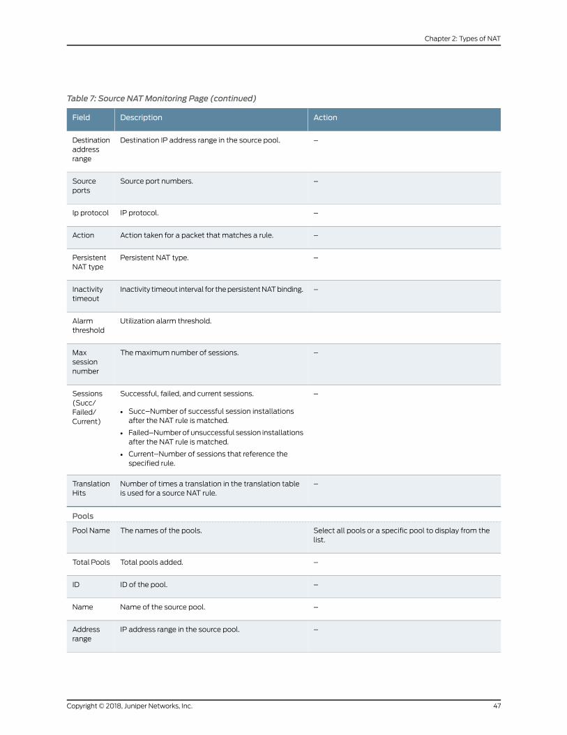
Table 7: Source NATMonitoring Page (continued)
ActionDescriptionField
–Destination IP address range in the source pool.Destinationaddressrange
–Source port numbers.Sourceports
–IP protocol.Ip protocol
–Action taken for a packet that matches a rule.Action
–Persistent NAT type.PersistentNAT type
–Inactivity timeout interval for thepersistentNATbinding.Inactivitytimeout
Utilization alarm threshold.Alarmthreshold
–Themaximum number of sessions.Maxsessionnumber
–Successful, failed, and current sessions.
• Succ–Number of successful session installationsafter the NAT rule is matched.
• Failed–Numberof unsuccessful session installationsafter the NAT rule is matched.
• Current–Number of sessions that reference thespecified rule.
Sessions(Succ/Failed/Current)
–Number of times a translation in the translation tableis used for a source NAT rule.
TranslationHits
Pools
Select all pools or a specific pool to display from thelist.
The names of the pools.Pool Name
–Total pools added.Total Pools
–ID of the pool.ID
–Name of the source pool.Name
–IP address range in the source pool.Addressrange
47Copyright © 2018, Juniper Networks, Inc.
Chapter 2: Types of NAT

Table 7: Source NATMonitoring Page (continued)
ActionDescriptionField
–Number of allocated single and twin ports.Single/Twinports
–Source port number in the pool.Port
–Displays the type of address assignment.Addressassignment
–Utilization alarm threshold.Alarmthreshold
–Port overloading capacity.Portoverloadingfactor
–Name of the routing instance.Routinginstance
–Total IP address, IP address set, or address book entry.Totaladdresses
–Host base address of the original source IP addressrange.
Hostaddressbase
–Number of times a translation in the translation tableis used for source NAT.
Translationhits
Top 10 Translation Hits
–Displays the graph of top 10 translation hits.Graph
Persistent NAT
Persistent NAT table statistics
–Displays the total number of persistent NAT bindingsfor the FPC.
bindingtotal
–Number of persistent NAT bindings that are in use forthe FPC.
binding inuse
–Total number of persistent NAT enodes for the FPC.enodetotal
–Number of persistent NAT enodes that are in use forthe FPC.
enode inuse
Persistent NAT table
Select all pools or a specific pool to display from thelist.
Name of the pool.SourceNAT pool
Copyright © 2018, Juniper Networks, Inc.48
Network Address Translation Feature Guide for Security Devices

Table 7: Source NATMonitoring Page (continued)
ActionDescriptionField
Selectall IPaddressesora specific IPaddress todisplayfrom the list.
Internal IP address.Internal IP
Select the port to display from the list.Displays the internal ports configured in the system.Internalport
Select all protocols or a specific protocol to displayfrom the list.
Internal protocols .Internalprotocol
–Internal transport IP address of the outgoing sessionfrom internal to external.
Internal IP
–Internal transport port number of the outgoing sessionfrom internal to external.
Internalport
–Internal protocol of the outgoing session from internalto external.
Internalprotocol
–Translated IP address of the source IP address.ReflectiveIP
–Displays the translated number of the port.Reflectiveport
–Translated protocol.Reflectiveprotocol
–Name of the source NAT pool where persistent NAT isused.
SourceNAT pool
–Persistent NAT type.Type
–Inactivity timeout period that remains and theconfigured timeout value.
Lefttime/Conftime
–Number of current sessions associated with thepersistent NAT binding and themaximum number ofsessions.
Currentsessionnum/Maxsessionnum
–Name of the source NAT rule to which this persistentNAT binding applies.
SourceNAT rule
External node table
–Internal transport IP address of the outgoing sessionfrom internal to external.
Internal IP
49Copyright © 2018, Juniper Networks, Inc.
Chapter 2: Types of NAT

Table 7: Source NATMonitoring Page (continued)
ActionDescriptionField
–Internal port number of the outgoing session frominternal to external.
Internalport
–External IPaddressof theoutgoingsession from internalto external.
External IP
–External port of the outgoing session from internal toexternal.
Externalport
–External zone of the outgoing session from internal toexternal.
Zone
Paired Address
Select all pools or a specific pool to display from thelist.
Name of the pool.Pool name
Select all addresses, or select the internal or externalIP address to display, and enter the IP address.
IP address.SpecifiedAddress
–Displays the selected pool or pools.Pool name
–Displays the internal IP address.Internaladdress
–Displays the external IP address.Externaladdress
Resource Usage
Utilization for all source pools
To view additional usage information for Port AddressTranslation (PAT) pools, select a pool name. Theinformation displays under Detail Port Utilization forSpecified Pool.
Name of the pool.Pool name
–Pool type: PAT or Non-PAT.Pool type
–Port overloading capacity for PAT pools.Portoverloadingfactor
–Addresses in the pool.Address
–Number of used resources in the pool.
For Non-PAT pools, the number of used IP addressesis displayed.
For PAT pools, the number of used ports is displayed.
Used
Copyright © 2018, Juniper Networks, Inc.50
Network Address Translation Feature Guide for Security Devices

Table 7: Source NATMonitoring Page (continued)
ActionDescriptionField
–Number of available resources in the pool.
For Non-PAT pools, the number of available IPaddresses is displayed.
For PAT pools, the number of available ports isdisplayed.
Available
–Number of used and available resources in the pool.
For Non-PAT pools, the total number of used andavailable IP addresses is displayed.
For PAT pools, the total number of used and availableports is displayed.
Total
–Percent of resources used.
For Non-PAT pools, the percent of IP addresses usedis displayed.
ForPATpools, thepercent of ports, including single andtwin ports, is displayed.
Usage
–Percent of resources used during the peak date andtime.
Peakusage
Detail Port Utilization for Specified Pool
Select the IP address for which you want to displaydetailed usage information.
IP addresses in the PAT pool.AddressName
–Index number.Factor-Index
–Displays the number of ports allocated at a time.Port-range
–Displays the number of used ports.Used
–Displays the number of available ports.Available
–Displays the number of used and available ports.Total
–Displays the percentage of ports used during the peakdate and time.
Usage
Source NAT Configuration Overview
Themain configuration tasks for source NAT are as follows:
51Copyright © 2018, Juniper Networks, Inc.
Chapter 2: Types of NAT
1. Configure an address pool or an interface NATmapping of private addresses to the
public address of an egress interface.
For an address pool, also do the following:
a. Specify thenameof thepool, theaddressesor address ranges, the routing instance,
and whether to perform port address translation (PAT).
b. (Optional) Configure address pool options, such as overflow pool, IP address
shifting, address sharing, address pooling, and pool utilization alarms.
c. ConfigureNATproxyARPentries for IP addresses in the samesubnet of the ingress
interface.
2. (Optional) Configure the persistent address.
3. Configure source NAT rules that align with your network and security requirements.
Example: Configuring Source NAT for Egress Interface Translation
This example describes how to configure a source NATmapping of private addresses to
the public address of an egress interface.
• Requirements on page 52
• Overview on page 52
• Configuration on page 54
• Verification on page 55
Requirements
Before you begin:
1. Configure network interfaces on the device. See Interfaces Feature Guide for Security
Devices.
2. Create security zonesandassign interfaces to them.SeeUnderstandingSecurity Zones.
Overview
This example uses the trust security zone for the private address space and the untrust
security zone for the public address space. In Figure 2 on page 53, devices with private
addresses in the trust zoneaccessapublicnetwork through theegress interfacege-0/0/0.
For packets that enter the Juniper Networks security device from the trust zone with a
destination address in the untrust zone, the source IP address is translated to the IP
address of the egress interface.
Copyright © 2018, Juniper Networks, Inc.52
Network Address Translation Feature Guide for Security Devices
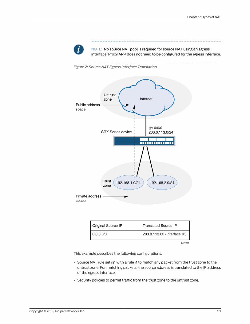
NOTE: No source NAT pool is required for source NAT using an egressinterface. Proxy ARP does not need to be configured for the egress interface.
Figure 2: Source NAT Egress Interface Translation
Trustzone
ge-0/0/0203.0.113.0/24SRX Series device
Untrustzone Internet
Public addressspace
Private addressspace
Original Source IP Translated Source IP
0.0.0.0/0 203.0.113.63 (Interface IP)
192.168.1.0/24 192.168.2.0/24
g030668
This example describes the following configurations:
• Source NAT rule set rs1with a rule r1 to match any packet from the trust zone to the
untrust zone. For matching packets, the source address is translated to the IP address
of the egress interface.
• Security policies to permit traffic from the trust zone to the untrust zone.
53Copyright © 2018, Juniper Networks, Inc.
Chapter 2: Types of NAT

Configuration
CLI QuickConfiguration
To quickly configure this example, copy the following commands, paste them into a text
file, remove any line breaks, change any details necessary to match your network
configuration, copy and paste the commands into the CLI at the [edit] hierarchy level,
and then enter commit from configuration mode.
set security nat source rule-set rs1 from zone trustset security nat source rule-set rs1 to zone untrustset security nat source rule-set rs1 rule r1 match source-address 0.0.0.0/0set security nat source rule-set rs1 rule r1 match destination-address 0.0.0.0/0set security nat source rule-set rs1 rule r1 then source-nat interfaceset security policies from-zone trust to-zone untrust policy internet-accessmatchsource-address any
set security policies from-zone trust to-zone untrust policy internet-accessmatchdestination-address any
set security policies from-zone trust to-zone untrust policy internet-accessmatchapplication any
set security policies from-zone trust to-zone untrust policy internet-access then permit
Step-by-StepProcedure
The following example requires you to navigate throughout various levels in the
configuration hierarchy. For instructions on how to do that, see Using the CLI Editor in
Configuration Mode.
To configure a source NAT translation to an egress interface:
1. Create a source NAT rule set.
[edit security nat source]user@host# set rule-set rs1 from zone trustuser@host# set rule-set rs1 to zone untrust
2. Configure a rule that matches packets and translates the source address to the
address of the egress interface.
[edit security nat source]user@host# set rule-set rs1 rule r1 match source-address 0.0.0.0/0user@host# set rule-set rs1 rule r1 match destination-address 0.0.0.0/0user@host# set rule-set rs1 rule r1 then source-nat interface
3. Configurea security policy that allows traffic fromthe trust zone to theuntrust zone.
[edit security policies from-zone trust to-zone untrust]user@host# set policy internet-accessmatch source-address anydestination-address any application any
user@host# set policy internet-access then permit
Copyright © 2018, Juniper Networks, Inc.54
Network Address Translation Feature Guide for Security Devices

Results From configuration mode, confirm your configuration by entering the show security nat
and show security policies commands. If the output does not display the intended
configuration, repeat the configuration instructions in this example to correct it.
[edit]user@host# show security natsource {rule-set rs1 {from zone trust;to zone untrust;rule r1 {match {source-address 0.0.0.0/0;destination-address 0.0.0.0/0;
}then {source-nat {interface;
}}
}}
}user@host# show security policiesfrom-zone trust to-zone untrust {policy internet-access {match {source-address any;destination-address any;application any;
}then {permit;
}}
}
If you are done configuring the device, enter commit from configuration mode.
Verification
To confirm that the configuration is working properly, perform these tasks:
• Verifying Source NAT Rule Usage on page 55
• Verifying NAT Application to Traffic on page 56
Verifying Source NAT Rule Usage
Purpose Verify that there is traffic matching the source NAT rule.
Action From operational mode, enter the show security nat source rule all command. View the
Translation hits field to check for traffic that matches the rule.
55Copyright © 2018, Juniper Networks, Inc.
Chapter 2: Types of NAT

Verifying NAT Application to Traffic
Purpose Verify that NAT is being applied to the specified traffic.
Action From operational mode, enter the show security flow session command.
Example: Configuring Source NAT for Single Address Translation
This example describes how to configure a source NATmapping of a single private
address to a public address.
• Requirements on page 56
• Overview on page 56
• Configuration on page 58
• Verification on page 60
Requirements
Before you begin:
1. Configure network interfaces on the device. See Interfaces Feature Guide for Security
Devices.
2. Create security zonesandassign interfaces to them.SeeUnderstandingSecurity Zones.
Overview
This example uses the trust security zone for the private address space and the untrust
security zone for thepublic address space. In Figure3onpage57, adevicewith theprivate
address 192.168.1.200 in the trust zone accesses a public network. For packets sent by
the device to a destination address in the untrust zone, the Juniper Networks security
device translates the source IP address to the public IP address 203.0.113.200/32.
Copyright © 2018, Juniper Networks, Inc.56
Network Address Translation Feature Guide for Security Devices

Figure 3: Source NAT Single Address Translation
192.168.1.200
Trustzone
ge-0/0/0203.0.113.0/24
ge-1/0/0192.168.1.0/24
SRX Series device
Untrustzone Internet
Public addressspace
Private addressspace
Original Source IP Translated Source IP
192.168.1.200/32 203.0.113.200/32
g030669
This example describes the following configurations:
• Source NAT pool src-nat-pool-1 that contains the IP address 203.0.113.200/32.
• Source NAT rule set rs1with rule r1 tomatch packets from the trust zone to the untrust
zone with the source IP address 192.168.1.200/32. For matching packets, the source
address is translated to the IP address in src-nat-pool-1 pool.
• Proxy ARP for the address 203.0.113.200 on interface ge-0/0/0.0. This allows the
Juniper Networks security device to respond to ARP requests received on the interface
for that address.
• Security policies to permit traffic from the trust zone to the untrust zone.
57Copyright © 2018, Juniper Networks, Inc.
Chapter 2: Types of NAT

Configuration
CLI QuickConfiguration
To quickly configure this example, copy the following commands, paste them into a text
file, remove any line breaks, change any details necessary to match your network
configuration, copy and paste the commands into the CLI at the [edit] hierarchy level,
and then enter commit from configuration mode.
set security nat source pool src-nat-pool-1 address 203.0.113.200/32set security nat source rule-set rs1 from zone trustset security nat source rule-set rs1 to zone untrustset security nat source rule-set rs1 rule r1 match source-address 192.168.1.200/32set security nat source rule-set rs1 rule r1 then source-nat pool src-nat-pool-1set security nat proxy-arp interface ge-0/0/0.0 address 203.0.113.200/32set security policies from-zone trust to-zone untrust policy internet-accessmatchsource-address any
set security policies from-zone trust to-zone untrust policy internet-accessmatchdestination-address any
set security policies from-zone trust to-zone untrust policy internet-accessmatchapplication any
set security policies from-zone trust to-zone untrust policy internet-access then permit
Step-by-StepProcedure
The following example requires you to navigate throughout various levels in the
configuration hierarchy. For instructions on how to do that, see Using the CLI Editor in
Configuration Mode.
To configure a source NAT translation for a single IP address:
1. Create a source NAT pool.
[edit security nat source]user@host# set pool src-nat-pool-1 address 203.0.113.200/32
2. Create a source NAT rule set.
[edit security nat source]user@host# set rule-set rs1 from zone trustuser@host# set rule-set rs1 to zone untrust
3. Configure a rule that matches packets and translates the source address to the
address in the pool.
[edit security nat source]user@host# set rule-set rs1 rule r1 match source-address 192.168.1.200/32user@host# set rule-set rs1 rule r1 then source-nat pool src-nat-pool-1
4. Configure proxy ARP.
[edit security nat]
Copyright © 2018, Juniper Networks, Inc.58
Network Address Translation Feature Guide for Security Devices

user@host# set proxy-arp interface ge-0/0/0.0 address 203.0.113.200
5. Configurea security policy that allows traffic fromthe trust zone to theuntrust zone.
[edit security policies from-zone trust to-zone untrust]user@host# set policy internet-accessmatch source-address anydestination-address any application any
user@host# set policy internet-access then permit
Results From configuration mode, confirm your configuration by entering the show security nat
and show security policies commands. If the output does not display the intended
configuration, repeat the configuration instructions in this example to correct it.
[edit]user@host# show security natsource {pool src-nat-pool-1 {address {203.0.113.200/32;
}}rule-set rs1 {from zone trust;to zone untrust;rule r1 {match {source-address 192.168.1.200/32;
}then {source-nat {pool {src-nat-pool-1;
}}
}}
}}proxy-arp {interface ge-0/0/0.0 {address {203.0.113.200/32;
}}
}user@host# show security policiesfrom-zone trust to-zone untrust {policy internet-access {match {source-address any;destination-address any;
59Copyright © 2018, Juniper Networks, Inc.
Chapter 2: Types of NAT

application any;}then {permit;
}}
}
If you are done configuring the device, enter commit from configuration mode.
Verification
To confirm that the configuration is working properly, perform these tasks:
• Verifying Source NAT Pool Usage on page 60
• Verifying Source NAT Rule Usage on page 60
• Verifying NAT Application to Traffic on page 60
Verifying Source NAT Pool Usage
Purpose Verify that there is traffic using IP addresses from the source NAT pool.
Action From operational mode, enter the show security nat source pool all command. View the
Translation hits field to check for traffic using IP addresses from the pool.
Verifying Source NAT Rule Usage
Purpose Verify that there is traffic matching the source NAT rule.
Action From operational mode, enter the show security nat source rule all command. View the
Translation hits field to check for traffic that matches the rule.
Verifying NAT Application to Traffic
Purpose Verify that NAT is being applied to the specified traffic.
Action From operational mode, enter the show security flow session command.
Example: Configuring Source and Destination NAT Translations
This example describes how to configure both source and destination NATmappings.
• Requirements on page 61
• Overview on page 61
• Configuration on page 63
• Verification on page 66
Copyright © 2018, Juniper Networks, Inc.60
Network Address Translation Feature Guide for Security Devices
Requirements
Before you begin:
1. Configure network interfaces on the device. See Interfaces Feature Guide for Security
Devices.
2. Create security zonesandassign interfaces to them.SeeUnderstandingSecurity Zones.
Overview
This example uses the trust security zone for the private address space and the untrust
security zone for the public address space. In Figure 4 on page 62, the following
translations are performed on the Juniper Networks security device:
• The source IP address in packets sent by the device with the private address
192.168.1.200 in the trust zone to any address in the untrust zone is translated to a
public address in the range from 203.0.113.10 through 203.0.113.14.
• The destination IP address 203.0.113.100/32 in packets sent from the trust zone to the
untrust zone is translated to the address 10.1.1.200/32.
61Copyright © 2018, Juniper Networks, Inc.
Chapter 2: Types of NAT

Figure 4: Source and Destination NAT Translations
This example describes the following configurations:
• SourceNATpool src-nat-pool-1 that contains the IPaddress range203.0.113.10 through
203.0.113.14.
• Source NAT rule set rs1with rule r1 to match any packets from the trust zone to the
untrust zone. For matching packets, the source address is translated to an IP address
in the src-nat-pool-1 pool.
• Destination NAT pool dst-nat-pool-1 that contains the IP address 10.1.1.200/32.
• Destination NAT rule set rs1with rule r1 to match packets from the trust zone with the
destination IP address 203.0.113.100. For matching packets, the destination address
is translated to the IP address in the dst-nat-pool-1 pool.
• Proxy ARP for the addresses 203.0.113.10 through 203.0.113.14 and 203.0.113.100/32
on interface ge-0/0/0.0. This allows the Juniper Networks security device to respond
to ARP requests received on the interface for those addresses.
• Security policy to permit traffic from the trust zone to the untrust zone.
• Security policy to permit traffic from the untrust zone to the translated destination IP
addresses in the trust zone.
Copyright © 2018, Juniper Networks, Inc.62
Network Address Translation Feature Guide for Security Devices

Configuration
CLI QuickConfiguration
To quickly configure this example, copy the following commands, paste them into a text
file, remove any line breaks, change any details necessary to match your network
configuration, copy and paste the commands into the CLI at the [edit] hierarchy level,
and then enter commit from configuration mode.
set security nat source pool src-nat-pool-1 address 203.0.113.10/32 to 203.0.113.14/32set security nat source rule-set rs1 from zone trustset security nat source rule-set rs1 to zone untrustset security nat source rule-set rs1 rule r1 match source-address 0.0.0.0/0set security nat source rule-set rs1 rule r1 match destination-address 0.0.0.0/0set security nat source rule-set rs1 rule r1 then source-nat pool src-nat-pool-1set security nat destination pool dst-nat-pool-1 address 10.1.1.200/32set security nat destination rule-set rs1 from zone untrustsetsecuritynatdestination rule-set rs1 rule r1matchdestination-address203.0.113.100/32set security nat destination rule-set rs1 rule r1 then destination-nat pool dst-nat-pool-1setsecuritynatproxy-arp interfacege-0/0/0.0address203.0.113.10/32to203.0.113.24/32set security nat proxy-arp interface ge-0/0/0.0 address 203.0.113.100/32set security policies from-zone trust to-zone untrust policy internet-accessmatchsource-address any
set security policies from-zone trust to-zone untrust policy internet-accessmatchdestination-address any
set security policies from-zone trust to-zone untrust policy internet-accessmatchapplication any
set security policies from-zone trust to-zone untrust policy internet-access then permitset security address-book global address dst-nat-pool-1 10.1.1.200/32set security policies from-zone untrust to-zone trust policy dst-nat-pool-1-accessmatchsource-address any
set security policies from-zone untrust to-zone trust policy dst-nat-pool-1-accessmatchdestination-address dst-nat-pool-1
set security policies from-zone untrust to-zone trust policy dst-nat-pool-1-accessmatchapplication any
set security policies from-zone untrust to-zone trust policy dst-nat-pool-1-access thenpermit
Step-by-StepProcedure
The following example requires you to navigate throughout various levels in the
configuration hierarchy. For instructions on how to do that, see Using the CLI Editor in
Configuration Mode.
To configure the source and destination NAT translations:
1. Create a source NAT pool.
[edit security nat source]user@host# set pool src-nat-pool-1 address 203.0.113.10 to 203.0.113.14
2. Create a source NAT rule set.
[edit security nat source]user@host# set rule-set rs1 from zone trust
63Copyright © 2018, Juniper Networks, Inc.
Chapter 2: Types of NAT
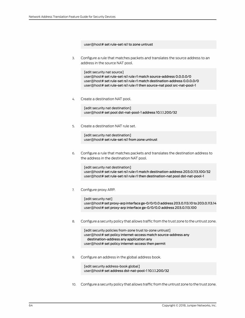
user@host# set rule-set rs1 to zone untrust
3. Configure a rule that matches packets and translates the source address to an
address in the source NAT pool.
[edit security nat source]user@host# set rule-set rs1 rule r1 match source-address 0.0.0.0/0user@host# set rule-set rs1 rule r1 match destination-address 0.0.0.0/0user@host# set rule-set rs1 rule r1 then source-nat pool src-nat-pool-1
4. Create a destination NAT pool.
[edit security nat destination]user@host# set pool dst-nat-pool-1 address 10.1.1.200/32
5. Create a destination NAT rule set.
[edit security nat destination]user@host# set rule-set rs1 from zone untrust
6. Configure a rule that matches packets and translates the destination address to
the address in the destination NAT pool.
[edit security nat destination]user@host# set rule-set rs1 rule r1 match destination-address 203.0.113.100/32user@host# set rule-set rs1 rule r1 then destination-nat pool dst-nat-pool-1
7. Configure proxy ARP.
[edit security nat]user@host# setproxy-arp interfacege-0/0/0.0address203.0.113.10 to203.0.113.14user@host# set proxy-arp interface ge-0/0/0.0 address 203.0.113.100
8. Configurea security policy that allows traffic fromthe trust zone to theuntrust zone.
[edit security policies from-zone trust to-zone untrust]user@host# set policy internet-accessmatch source-address anydestination-address any application any
user@host# set policy internet-access then permit
9. Configure an address in the global address book.
[edit security address-book global]user@host# set address dst-nat-pool-1 10.1.1.200/32
10. Configurea security policy that allows traffic fromtheuntrust zone to the trust zone.
Copyright © 2018, Juniper Networks, Inc.64
Network Address Translation Feature Guide for Security Devices

[edit security policies from-zone untrust to-zone trust]user@host# set policy dst-nat-pool-1-accessmatch source-address anydestination-address dst-nat-pool-1 application any
user@host# set policy dst-nat-pool-1-access then permit
Results From configuration mode, confirm your configuration by entering the show security nat
and show security policies commands. If the output does not display the intended
configuration, repeat the configuration instructions in this example to correct it.
[edit]user@host# show security natsource {pool src-nat-pool-1 {address {203.0.113.10/32 to 203.0.113.14/32;
}}rule-set rs1 {to zone untrust;rule r1 {match {source-address 0.0.0.0/0;destination-address 0.0.0.0/0;
}then {source-nat {pool {src-nat-pool-1;
}}
}}
}}destination {pool dst-nat-pool-1 {address 10.1.1.200/32;
}rule-set rs1 {from zone untrust;rule r1 {match {destination-address 203.0.113.100/32;
}then {destination-nat pool dst-nat-pool-1;
}}
}}proxy-arp {interface ge-0/0/0.0 {
65Copyright © 2018, Juniper Networks, Inc.
Chapter 2: Types of NAT

address {203.0.113.10/32 to 203.0.113.14/32;203.0.113.100/32;
}}
}user@host# show security policiesfrom-zone trust to-zone untrust {policy internet-access {match {source-address any;destination-address any;application any;
}}policy internet-access {then {permit;
}}
}from-zone untrust to-zone trust {policy dst-nat-pool-1-access {match {source-address any;destination-address dst-nat-pool-1;application any;
}then {permit;
}}
}
If you are done configuring the device, enter commit from configuration mode.
Verification
To confirm that the configuration is working properly, perform these tasks:
• Verifying Source NAT Pool Usage on page 66
• Verifying Source NAT Rule Usage on page 67
• Verifying Destination NAT Pool Usage on page 67
• Verifying Destination NAT Rule Usage on page 67
• Verifying NAT Application to Traffic on page 67
Verifying Source NAT Pool Usage
Purpose Verify that there is traffic using IP addresses from the source NAT pool.
Action From operational mode, enter the show security nat source pool all command. View the
Translation hits field to check for traffic using IP addresses from the pool.
Copyright © 2018, Juniper Networks, Inc.66
Network Address Translation Feature Guide for Security Devices

Verifying Source NAT Rule Usage
Purpose Verify that there is traffic matching the source NAT rule.
Action From operational mode, enter the show security nat source rule all command. View the
Translation hits field to check for traffic that matches the rule.
Verifying Destination NAT Pool Usage
Purpose Verify that there is traffic using IP addresses from the destination NAT pool.
Action From operational mode, enter the show security nat destination pool all command. View
the Translation hits field to check for traffic using IP addresses from the pool.
Verifying Destination NAT Rule Usage
Purpose Verify that there is traffic matching the destination NAT rule.
Action From operational mode, enter the show security nat destination rule all command. View
the Translation hits field to check for traffic that matches the rule.
Verifying NAT Application to Traffic
Purpose Verify that NAT is being applied to the specified traffic.
Action From operational mode, enter the show security flow session command.
Understanding Source NAT Rules
Source NAT rules specify two layers of match conditions:
• Traffic direction—Allows you to specify combinations of from interface, from zone, or
from routing-instance and to interface, to zone, or to routing-instance. You cannot
configure the same from and to contexts for different rule sets.
• Packet information—Can be source and destination IP addresses or subnets, source
port numbers or port ranges, destination port numbers or port ranges, protocols, or
applications.
For all ALG traffic, except FTP, we recommend that you not use the source-port rule
option. Data session creation can fail if this option is used because the IP address and
the source port value, which is a random value, might not match the rule.
Inaddition,we recommendthat younotuse thedestination-portoptionor theapplication
option as matching conditions for ALG traffic. If these options are used, translation may
fail because the port value in the application payloadmight not match the port value in
the IP address.
67Copyright © 2018, Juniper Networks, Inc.
Chapter 2: Types of NAT

If multiple source NAT rules overlap in the match conditions, the most specific rule is
chosen. For example, if rules A and B specify the same source and destination IP
addresses, but rule A specifies traffic from zone 1 to zone 2 and rule B specifies traffic
from zone 1 to interface ge-0/0/0, rule B is used to perform source NAT. An interface
match is considered to bemore specific than a zonematch, which is more specific than
a routing instancematch.
The actions you can specify for a source NAT rule are:
• off—Do not perform source NAT.
• pool—Use the specified user-defined address pool to perform source NAT.
• interface—Use the egress interface’s IP address to perform source NAT.
Source NAT rules are applied to traffic in the first packet that is processed for the flow
or in the fast path for the ALG. Source NAT rules are processed after static NAT rules,
destination NAT rules, and reverse mapping of static NAT rules and after route and
security policy lookup.
When zones are not configured under rule-set andwhen active source NAT is configured
withmissingmandatory statement “from” then, the followingmessage isdisplayedwhen
performing commit “Missingmandatory statement: 'from' error: configuration check-out
failed” and the configuration check-out fails.
Example: Configuring Source NATwithMultiple Rules
This example describes how to configure source NATmappings with multiple rules.
• Requirements on page 68
• Overview on page 68
• Configuration on page 71
• Verification on page 74
Requirements
Before you begin:
• Configure network interfaces on the device. See Interfaces Feature Guide for Security
Devices.
• Create security zones andassign interfaces to them.SeeUnderstandingSecurity Zones.
Overview
This example uses the trust security zone for the private address space and the untrust
security zone for the public address space. In Figure 5 on page 69, the following
translations are performed on the Juniper Networks security device for the source NAT
mapping for traffic from the trust zone to the untrust zones:
• The source IP address in packets sent by the 10.1.1.0/24 and 10.1.2.0/24 subnets to any
address in the untrust zone is translated to a public address in the range from 192.0.2.1
to 192.0.2.24 with port translation.
Copyright © 2018, Juniper Networks, Inc.68
Network Address Translation Feature Guide for Security Devices
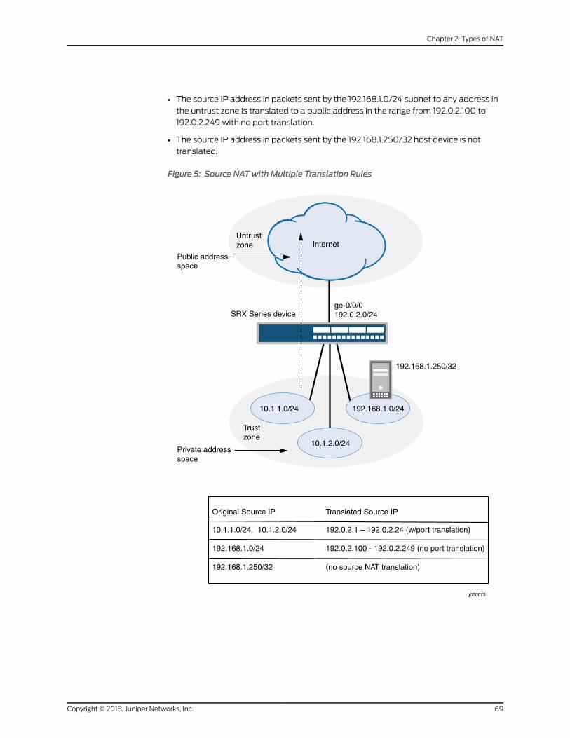
• The source IP address in packets sent by the 192.168.1.0/24 subnet to any address in
the untrust zone is translated to a public address in the range from 192.0.2.100 to
192.0.2.249 with no port translation.
• The source IP address in packets sent by the 192.168.1.250/32 host device is not
translated.
Figure 5: Source NATwith Multiple Translation Rules
Trustzone
ge-0/0/0192.0.2.0/24SRX Series device
Untrustzone Internet
Public addressspace
Private addressspace
Original Source IP Translated Source IP
10.1.1.0/24, 10.1.2.0/24
192.168.1.0/24
192.168.1.250/32
192.0.2.1 – 192.0.2.24 (w/port translation)
192.0.2.100 - 192.0.2.249 (no port translation)
(no source NAT translation)
10.1.1.0/24 192.168.1.0/24
10.1.2.0/24
192.168.1.250/32
g030673
69Copyright © 2018, Juniper Networks, Inc.
Chapter 2: Types of NAT

This example describes the following configurations:
• Source NAT pool src-nat-pool-1 that contains the IP address range 192.0.2.1 through
192.0.2.24.
• SourceNATpool src-nat-pool-2 that contains the IP address range 192.0.2.100 through
192.0.2.249, with port address translation disabled.
NOTE: When port address translation is disabled, the number oftranslations that the source NAT pool can support concurrently is limitedto the number of addresses in the pool, unless the address-shared option
is enabled. Packets are dropped if there are no addresses available in thesource NAT pool. You can optionally specify an overflow pool fromwhichIP addresses and port numbers are allocatedwhen there are no addressesavailable in the original source NAT pool.
• Source NAT rule set rs1 to match packets from the trust zone to the untrust zone. Rule
set rs1 contains multiple rules:
• Rule r1 tomatchpacketswitha source IPaddress in either the 10.1.1.0/24or 10.1.2.0/24
subnets. For matching packets, the source address is translated to an IP address in
the src-nat-pool-1 pool.
• Rule r2 tomatch packets with a source IP address of 192.168.1.250/32. Formatching
packets, there is no NAT translation performed.
• Rule r3 to match packets with a source IP address in the 192.168.1.0/24 subnet. For
matching packets, the source address is translated to an IP address in the
src-nat-pool-2 pool.
NOTE: The order of rules in a rule set is important, as the first rule in therule set that matches the traffic is used. Therefore, rule r2 to match a
specific IPaddressmustbeplacedbefore rule r3 thatmatches thesubnet
on which the device is located.
• Proxy ARP for the addresses 192.0.2.1 through 192.0.2.24 and 192.0.2.100 through
192.0.2.249 on interface ge-0/0/0.0. This allows the Juniper Networks security device
to respond to ARP requests received on the interface for those addresses.
• Security policies to permit traffic from the trust zone to the untrust zone.
On SRX4600 devices, when you configure source NAT rule or pool with rule name or
pool nameas interface or service-set youwill receive the following errormessage: syntax
error, expecting <data>.
• If there is a source NAT rule named interface, the rule cannot be viewed using the show
security nat source rule interface command.
• If there is a source NAT rule named service-set, the rule cannot be viewed using the
show security nat source rule service-set command.
Copyright © 2018, Juniper Networks, Inc.70
Network Address Translation Feature Guide for Security Devices

• If there is a source NAT pool named interface, the pool cannot be viewed using the
show security nat source pool interface command.
• If there is a source NAT pool named service-set, the pool cannot be viewed using the
show security nat source pool service-set command.
• If there is a source NAT pool named interface, the paired-address cannot be viewed
using the show security nat source paired-address pool-name interface command.
• If there is a source NAT pool named service-set, the paired-address cannot be viewed
using the show security nat source paired-address pool-name service-set command.
Configuration
CLI QuickConfiguration
To quickly configure this example, copy the following commands, paste them into a text
file, remove any line breaks, change any details necessary to match your network
configuration, copy and paste the commands into the CLI at the [edit] hierarchy level,
and then enter commit from configuration mode.
set security nat source pool src-nat-pool-1 address 192.0.2.1/32 to 192.0.2.24/32set security nat source pool src-nat-pool-2 address 192.0.2.100/32 to 192.0.2.249/32set security nat source pool src-nat-pool-2 port no-translationset security nat source rule-set rs1 from zone trustset security nat source rule-set rs1 to zone untrustset security nat source rule-set rs1 rule r1 match source-address 10.1.1.0/24set security nat source rule-set rs1 rule r1 match source-address 10.1.2.0/24set security nat source rule-set rs1 rule r1 match destination-address 0.0.0.0/0set security nat source rule-set rs1 rule r1 then source-nat pool src-nat-pool-1set security nat source rule-set rs1 rule r2match source-address 192.168.1.250/32set security nat source rule-set rs1 rule r2match destination-address 0.0.0.0/0set security nat source rule-set rs1 rule r2 then source-nat offset security nat source rule-set rs1 rule r3match source-address 192.168.1.0/24set security nat source rule-set rs1 rule r3match destination-address 0.0.0.0/0set security nat source rule-set rs1 rule r3 then source-nat pool src-nat-pool-2set security nat proxy-arp interface ge-0/0/0.0 address 192.0.2.1/32 to 192.0.2.24/32set securitynatproxy-arp interfacege-0/0/0.0address 192.0.2.100/32 to 192.0.2.249/32set security policies from-zone trust to-zone untrust policy internet-accessmatchsource-address any
set security policies from-zone trust to-zone untrust policy internet-accessmatchdestination-address any
set security policies from-zone trust to-zone untrust policy internet-accessmatchapplication any
set security policies from-zone trust to-zone untrust policy internet-access then permit
Step-by-StepProcedure
The following example requires you to navigate throughout various levels in the
configuration hierarchy. For instructions on how to do that, see Using the CLI Editor in
Configuration Mode.
To configure multiple source NAT rules in a rule set:
1. Create a source NAT pool.
[edit security nat source]
71Copyright © 2018, Juniper Networks, Inc.
Chapter 2: Types of NAT

user@host# set pool src-nat-pool-1 address 192.0.2.1 to 192.0.2.24
2. Create a source NAT pool with no port translation.
[edit security nat source]user@host# set pool src-nat-pool-2 address 192.0.2.100 to 192.0.2.249user@host# set pool src-nat-pool-2 port no-translation
NOTE: Toconfigureanoverflowpool for src-nat-pool-2using theegress
interface:
[edit security nat source]user@host# set pool src-nat-pool-2 overflow-pool interface
3. Create a source NAT rule set.
[edit security nat source]user@host# set rule-set rs1 from zone trustuser@host# set rule-set rs1 to zone untrust
4. Configure a rule that matches packets and translates the source address to an
address in the pool.
[edit security nat source]user@host# set rule-set rs1 rule r1 match source-address [10.1.1.0/24 10.1.2.0/24]user@host# set rule-set rs1 rule r1 match destination-address 0.0.0.0/0user@host# set rule-set rs1 rule r1 then source-nat pool src-nat-pool-1
5. Configure a rule to match packets for which the source address is not translated.
[edit security nat source]user@host# set rule-set rs1 rule r2match source-address 192.168.1.250/32user@host# set rule-set rs1 rule r2match destination-address 0.0.0.0/0user@host# set rule-set rs1 rule r2 then source-nat off
6. Configure a rule to match packets and translate the source address to an address
in the pool with no port translation.
[edit security nat source]user@host# set rule-set rs1 rule r3match source-address 192.168.1.0/24user@host# set rule-set rs1 rule r3match destination-address 0.0.0.0/0user@host# set rule-set rs1 rule r3 then source-nat pool src-nat-pool-2
7. Configure proxy ARP.
Copyright © 2018, Juniper Networks, Inc.72
Network Address Translation Feature Guide for Security Devices

[edit security nat]user@host# set proxy-arp interface ge-0/0/0.0 address 192.0.2.1 to 192.0.2.24user@host# set proxy-arp interface ge-0/0/0.0 address 192.0.2.100 to 192.0.2.249
8. Configurea security policy that allows traffic fromthe trust zone to theuntrust zone.
[edit security policies from-zone trust to-zone untrust]user@host# set policy internet-accessmatch source-address anydestination-address any application any
user@host# set policy internet-access then permit
Results From configuration mode, confirm your configuration by entering the show security nat
and show security policies commands. If the output does not display the intended
configuration, repeat the configuration instructions in this example to correct it.
[edit]user@host# show security natsource {pool src-nat-pool-1 {address {192.0.2.1/32 to 192.0.2.24/32;
}}pool src-nat-pool-2 {address {192.0.2.100/32 to 192.0.2.249/32;
}port no-translation;
}rule-set rs1 {from zone trust;to zone untrust;rule r1 {match {source-address [ 10.1.1.0/24 10.1.2.0/24 ];destination-address 0.0.0.0/0;
}then {source-nat {pool {src-nat-pool-1;
}}
}}rule r2 {match {source-address 192.168.1.250/32;destination-address 0.0.0.0/0;
}then {
73Copyright © 2018, Juniper Networks, Inc.
Chapter 2: Types of NAT

source-nat {off;
}}
}rule r3 {match {source-address 192.168.1.0/24;destination-address 0.0.0.0/0;
}then {source-nat {pool {src-nat-pool-2;
}}
}}
}}proxy-arp {interface ge-0/0/0.0 {address {192.0.2.1/32 to 192.0.2.24/32;192.0.2.100/32 to 192.0.2.249/32;
}}
}user@host# show security policiesfrom-zone trust to-zone untrust {policy internet-access {match {source-address any;destination-address any;application any;
}then {permit;
}}
}
If you are done configuring the device, enter commit from configuration mode.
Verification
To confirm that the configuration is working properly, perform these tasks:
• Verifying Source NAT Pool Usage on page 75
• Verifying Source NAT Rule Usage on page 75
• Verifying NAT Application to Traffic on page 75
Copyright © 2018, Juniper Networks, Inc.74
Network Address Translation Feature Guide for Security Devices

Verifying Source NAT Pool Usage
Purpose Verify that there is traffic using IP addresses from the source NAT pool.
Action From operational mode, enter the show security nat source pool all command. View the
Translation hits field to check for traffic using IP addresses from the pool.
Verifying Source NAT Rule Usage
Purpose Verify that there is traffic matching the source NAT rule.
Action From operational mode, enter the show security nat source rule all command. View the
Translation hits field to check for traffic that matches the rule.
Verifying NAT Application to Traffic
Purpose Verify that NAT is being applied to the specified traffic.
Action From operational mode, enter the show security flow session command.
Understanding Source NAT Pools
A NAT pool is a user-defined set of IP addresses that are used for translation. Unlike
static NAT, where there is a one-to-onemapping that includes destination IP address
translation in one direction and source IP address translation in the reverse direction,
with source NAT, you translate the original source IP address to an IP address in the
address pool.
For source Network Address Translation (NAT) address pools, specify the following:
• Name of the source NAT address pool.
• Up to eight address or address ranges.
NOTE: Do not overlap NAT addresses for source NAT, destination NAT,and static NATwithin one routing instance.
• Routing instance—Routing instance towhich the pool belongs (the default is themain
inet.0 routing instance).
• Port —The Port Address Translation (PAT) for a source pool. By default, PAT is
performed with source NAT. If you specify the no-translation option, the number of
hosts that the source NAT pool can support is limited to the number of addresses in
the pool. If you specify block-allocation, a block of ports is allocated for translation,
instead of individual ports being allocated. If you specify deterministic, an incoming
(source) IP address and port alwaysmap to the specific destination address and port
block, basedonpredefined, deterministicNATalgorithm. If youspecifyport-overloading,
75Copyright © 2018, Juniper Networks, Inc.
Chapter 2: Types of NAT

you can configure the port overloading capacity in source NAT. If you specify range,
you can provide the port number range attached to each address in the pool, and the
twin port range for source NAT pools.
• Overflow pool (optional)—Packets are dropped if there are no addresses available in
the designated source NAT pool. To prevent that from happening when the port
no-translation option is configured, you can specify an overflow pool. Once addresses
from the original source NAT pool are exhausted, IP addresses and port numbers are
allocated fromtheoverflowpool. Auser-definedsourceNATpool or anegress interface
can be used as the overflow pool. (When the overflow pool is used, the pool ID is
returned with the address.)
• IP address shifting (optional)—A range of original source IP addresses can bemapped
to another range of IP addresses, or to a single IP address, by shifting the IP addresses.
Specify the host-address-base option with the base address of the original source IP
address range.
• Addresssharing(optional)—Multiple internal IPaddressescanbemappedto thesame
external IP address. This option can be used only when the source NAT pool is
configured with no port translation. Specify the address-shared option when a source
NATpool has fewexternal IP addresses available, or only one external IP address.With
amany-to-onemapping, use of this option increases NAT resources and improves
traffic.
• Addresspooling (optional)—Addresspoolingcanbeconfiguredaspairedorno-paired.
Specify address-pooling paired for applications that require all sessions associated
with one internal IP address to bemapped to the same external IP address for the
durationofasession.Thisdiffers fromthepersistent-addressoption, inwhich thesame
internal address is translated to the same external address every time. Specify
address-pooling no-paired for applications that can be can be assigned IP addresses
in a round-robin fashion. If either address-pooling paired or address-pooling no-paired
is configured for a source NAT pool with PAT, the persistent address option is disabled.
If address-shared is configured on a source NAT pool without PAT, then the
persistent-address option is enabled. Both address-shared and address-pooling paired
can be configured on the same source NAT pool without PAT.
• Pool utilization alarm (optional)—When the raise-threshold option is configured for
source NAT, an SNMP trap is triggered if the source NAT pool utilization rises above
this threshold. If the optional clear-threshold option is configured, an SNMP trap is
triggered if the sourceNATpool utilizationdropsbelow this threshold. If clear-threshold
is not configured, it is set by default to 80 percent of the raise-threshold value.
You can use the show security nat resource usage source pool command to view address
use in a source NAT pool without PAT, and to view port use in a source NAT pool with
PAT.
Copyright © 2018, Juniper Networks, Inc.76
Network Address Translation Feature Guide for Security Devices

Understanding Source NAT Pool Capacities
Maximum capacities for source pools and IP addresses on SRX300, SRX320, SRX340,
SRX345 and SRX650 devices are as follows:
SRX650SRX340SRX345
SRX300SRX320
Pool/PATMaximumAddress Capacity
102420481024Source NAT pools
102420481024IP addresses supportingport translation
64M64M64MPAT port number
Maximumcapacities for sourcepoolsand IPaddressesonSRX1400,SRX1500,SRX3400,
SRX3600, SRX4100, SRX4200, SRX5400, SRX5600, and SRX5800 devices are as
follows:
SRX5400SRX5600SRX5800
SRX4100SRX4200
SRX3400SRX3600
SRX1400SRX1500
Pool/PATMaximumAddressCapacity
12,28810,24010,2408192Source NAT pools
1M12,28812,2888192IP addressessupporting porttranslation
384M384M384M256MPAT port number
NOTE: In Release 12.3X48-D40, and in Release 15.1X49-D60 and laterreleases, youcan increase thesourceNATport capacity to2.4GonSRX5400,SRX5600, and SRX5800 devices with next-generation Services ProcessingCards (SPCs) using the port-scaling-enlargement statement at the [edit
security nat source] hierarchy level supported .
NOTE: Platformsupportdependson the JunosOSrelease inyour installation.
Increasing the total number of IP addresses used for source NAT, either by increasing the
number of pools in the configuration and/or by increasing the capacity or IP-addresses
per pool, consumesmemory needed for port allocation. When source NAT pool and IP
address limits are reached, port ranges shouldbe reassigned. That is, the number of ports
for each IP address should be decreased when the number of IP addresses and source
NAT pools is increased. This ensures NAT does not consume toomuchmemory.
77Copyright © 2018, Juniper Networks, Inc.
Chapter 2: Types of NAT
Forexample, inasourceNATpool forSRX5000devices,when thenumberof IPaddresses
supporting port translation reaches the limit of 1M, the total number of PAT ports is 64G,
which exceeds the 384M limitation. This is because, by default, each IP address supports
64,512 ports. To ensure that PAT port numbers are within capacity, the port range for
each IP needs to be configured to decrease the total number of PAT ports.
Use the range and range twin-port options at the [edit security nat source pool port]
hierarchy level to assign a new port range or twin port range for a specific pool. Use the
pool-default-port-rangeand thepool-default-twin-port-rangeoptionsat the [edit security
nat source] hierarchy level to specify the global default port range or twin port range for
all source NAT pools.
Configuring port overloading should also be done carefully when source NAT pools are
increased.
For a source pool with PAT in range (63,488 through 65,535), two ports are allocated
at one time for RTP/RTCP applications, such as SIP, H.323, and RTSP. In these scenarios,
each IP address supports PAT, occupying 2048 ports (63,488 through 65,535) for ALG
module use.
Understanding Persistent Addresses for Source NAT Pools
By default, port address translation is performed with source NAT. However, an original
source address may not be translated to the same IP address for different traffic that
originates from the same host. The source NAT address-persistent option ensures that
the same IP address is assigned from the source NAT pool to a specific host for multiple
concurrent sessions.
This option differs from the address-pooling paired option, where the internal address
is mapped to an external address within the pool on a first-come, first-served basis, and
might bemapped to a different external address for each session.
Example: Configuring Capacity for Source NAT Pools with PAT
This example describes how to configure the capacity of source NAT pools with Port
Address Translation (PAT) if a default port range is not set or you want to override it.
Translations are set for each IP address.When the source pool is increased, ports should
be reassigned if the current port number exceeds limitations.
• Requirements on page 78
• Overview on page 79
• Configuration on page 79
• Verification on page 80
Requirements
Before you begin:
1. Configure network interfaces on the device. See Interfaces Feature Guide for Security
Devices.
Copyright © 2018, Juniper Networks, Inc.78
Network Address Translation Feature Guide for Security Devices

2. Create security zonesandassign interfaces to them.SeeUnderstandingSecurity Zones.
Overview
This example shows how to configure a PAT pool of 2048 IP addresses with 32,000
ports for each IP address.
Configuration
CLI QuickConfiguration
To quickly configure this example, copy the following commands, paste them into a text
file, remove any line breaks, change any details necessary to match your network
configuration, copy and paste the commands into the CLI at the [edit] hierarchy level,
and then enter commit from configuration mode.
[edit security nat source]set pool src-nat-pat-addr address 192.168.0.0/32 to 192.168.3.255/32set pool src-nat-pat-addr address 192.168.4.0/32 to 192.168.7.255/32set pool-default-port-range 2001set pool-default-port-range to 32720
Step-by-StepProcedure
The following example requires you to navigate throughout various levels in the
configuration hierarchy. For instructions on how to do that, see Using the CLI Editor in
Configuration Mode.
To configure capacity for a source NAT pool with PAT:
1. Specify a source NAT pool with PAT and an IP address range.
[edit security nat source]user@host# set pool src-nat-pat-addr address 192.168.0.0/32 to 192.168.3.255/32user@host#set pool src-nat-pat-addr address 192.168.4.0/32 to 192.168.7.255/32
2. Specify a default port range for the source pool.
[edit security nat source]user@host# set pool-default-port-range 2001user@host# set pool-default-port-range to 32720
Results From configuration mode, confirm your configuration by entering the show security
nat-source-summarycommand. If theoutputdoesnotdisplay the intendedconfiguration,
repeat the configuration instructions in this example to correct it.
user@host> run show security nat source summary
Total port number usage for port translation pool: 16515072Maximum port number for port translation pool: 134217728Total pools: 1
Pool Address Routing PAT Total Name Range Instance Address pool2 203.0.113.1 - 203.0.113.3 default yes 2048
79Copyright © 2018, Juniper Networks, Inc.
Chapter 2: Types of NAT

Name Range Instance Addresspool1 198.51.100.0 - 198.51.100.255 default yes 256
Total rules: 1Rule name Rule set From To Actionrule 1 ruleset1 ge-2/2/2.0 ge-2/2/3.0 pool1rule 1 ge-2/2/4.0 ge-2/2/5.0
If you are done configuring the device, enter commit from configuration mode.
Verification
Verifying Capacity of Source NAT Pools
Purpose View port and pool information. Port limitations are automatically checked, so the
configuration will not be committed if port limitations are exceeded.
Action From operational mode, enter the show security nat source summary command to view
port and pool details.
Understanding Source NAT Pools with Address Pooling
When a host initiates several sessions that match a policy that requires NAT, and is
assigned an IP address from a source pool that has port address translation enabled, a
different source IP address is used for each session.
Because someapplications require the same source IP address for each session, you can
use theaddress-poolingpaired feature to enableall sessionsassociatedwithone internal
IP address tomap to the sameexternal IP address for the duration of the sessions.When
thesessionsend, themappingbetween the internal IPaddressand theexternal IPaddress
ceases. The next time the host initiates a session, a different IP address from the pool
might be assigned to it.
This differs from the source NAT address-persistent feature, which keeps the mapping
static; the same internal IP address is mapped to the same external IP address every
time. It also differs from the address-persistent feature in that address-pooling paired is
configured for a specific pool. The address-persistent feature is a global configuration
that applies to all source pools.
Understanding Source NAT Pools with Address Shifting
Thematch conditions for a source NAT rule set do not allow you to specify an address
range; only address prefixes may be specified in a rule. When configuring a source NAT
pool, you can specify the host-base-address option; this option specifies the IP address
where the original source IP address range begins.
The rangeoforiginal source IPaddresses thatare translated isdeterminedby thenumber
of addresses in the source NAT pool. For example, if the source NAT pool contains a
range of ten IP addresses, then up to ten original source IP addresses can be translated,
Copyright © 2018, Juniper Networks, Inc.80
Network Address Translation Feature Guide for Security Devices

starting with a specified base address. This type of translation is one-to-one, static, and
without port address translation.
Thematch condition in a source NAT rule may define a larger address range than that
specified in thesourceNATpool. For example, amatchconditionmight specifyanaddress
prefix that contains 256 addresses, but the source NAT pool might contain a range of
only a few IP addresses, or only one IP address. A packet’s source IP address canmatch
a source NAT rule, but if the source IP address is not within the address range specified
in the source NAT pool, the source IP address is not translated.
Example: Configuring Source NAT Pools with Address Shifting
This example describes how to configure a source NATmapping of a private address
range to public addresses, with optional address shifting. This mapping is one-to-one
between the original source IP addresses and translated IP addresses.
NOTE: Thematch conditions for a source NAT rule set do not allow you tospecify an address range; only address prefixesmay be specified in a rule.When configuring a source NAT pool, you can specify the host-base-address
option; this option specifies the IP address where the original source IPaddress range begins, and disables port translation.
The range of original source IP addresses that are translated is determinedby thenumberofaddresses in thesourceNATpool. Forexample, if thesourceNAT pool contains a range of ten IP addresses, then up to ten original sourceIP addresses can be translated, starting with a specified base address.
Thematch condition in a source NAT rule may define a larger address rangethan that specified in the source NAT pool. For example, a match conditionmight specify an address prefix that contains 256 addresses, but the sourceNAT pool contains a range of only ten IP addresses. A packet’s source IPaddresscanmatchasourceNATrule,but if thesource IPaddress isnotwithinthe address range specified in the source NAT pool, the source IP address isnot translated.
• Requirements on page 81
• Overview on page 82
• Configuration on page 83
• Verification on page 85
Requirements
Before you begin:
• Configure network interfaces on the device. See Interfaces Feature Guide for Security
Devices.
• Create security zones andassign interfaces to them.SeeUnderstandingSecurity Zones.
81Copyright © 2018, Juniper Networks, Inc.
Chapter 2: Types of NAT

Overview
This example uses the trust security zone for the private address space and the untrust
security zone for the public address space. In Figure 6 on page 82, a range of private
addresses in the trust zone ismapped to a range of public addresses in the untrust zone.
For packets sent from the trust zone to the untrust zone, a source IP address in the range
of 192.168.1.10/32 through 192.168.1.20/32 is translated to a public address in the range
of 203.0.113.30/32 through 203.0.113.40/32.
Figure 6: Source NATwith Address Shifting
Trustzone
ge-0/0/0203.0.113.0/24
ge-1/0/0192.168.1.0/24
SRX Series device
Untrustzone Internet
Public addressspace
Private addressspace
Original Source IP Translated Source IP
192.168.1.10/32 - 192.168.1.20/32 203.0.113.30/32 - 203.0.113.40/32
g030672
Copyright © 2018, Juniper Networks, Inc.82
Network Address Translation Feature Guide for Security Devices

This example describes the following configurations:
• Source NAT pool src-nat-pool-1 that contains the IP address range 203.0.113.30/32
through 203.0.113.40/32. For this pool, the beginning of the original source IP address
range is 192.168.1.10/32 and is specified with the host-address-base option.
• Source NAT rule set rs1with rule r1 tomatch packets from the trust zone to the untrust
zone with a source IP address in the 192.168.1.0/24 subnet. For matching packets that
fall within the source IP address range specified by the src-nat-pool-1 configuration,
the source address is translated to the IP address in src-nat-pool-1 pool.
• Proxy ARP for the addresses 203.0.113.30/32 through 203.0.113.40/32 on interface
ge-0/0/0.0. This allows the Juniper Networks security device to respond to ARP
requests received on the interface for that address.
• Security policies to permit traffic from the trust zone to the untrust zone.
Configuration
CLI QuickConfiguration
To quickly configure this example, copy the following commands, paste them into a text
file, remove any line breaks, change any details necessary to match your network
configuration, copy and paste the commands into the CLI at the [edit] hierarchy level,
and then enter commit from configuration mode.
set security nat source pool src-nat-pool-1 address 203.0.113.30/32 to 203.0.113.40/32set security nat source pool src-nat-pool-1 host-address-base 192.168.1.10/32set security nat source rule-set rs1 from zone trustset security nat source rule-set rs1 to zone untrustset security nat source rule-set rs1 rule r1 match source-address 192.168.1.0/24set security nat source rule-set rs1 rule r1 then source-nat pool src-nat-pool-1set security nat proxy-arp interface ge-0/0/0.0 address 203.0.113.30/32 to203.0.113.40/32
set security policies from-zone trust to-zone untrust policy internet-accessmatchsource-address any
set security policies from-zone trust to-zone untrust policy internet-accessmatchdestination-address any
set security policies from-zone trust to-zone untrust policy internet-accessmatchapplication any
set security policies from-zone trust to-zone untrust policy internet-access then permit
Step-by-StepProcedure
The following example requires you to navigate throughout various levels in the
configuration hierarchy. For instructions on how to do that, see Using the CLI Editor in
Configuration Mode.
To configure a source NATmapping with address shifting:
1. Create a source NAT pool.
[edit security nat source]user@host# set pool src-nat-pool-1 address 203.0.113.30/32 to 203.0.113.40/32
2. Specify the beginning of the original source IP address range.
83Copyright © 2018, Juniper Networks, Inc.
Chapter 2: Types of NAT

[edit security nat source]user@host# set pool src-nat-pool-1 host-address-base 192.168.1.10/32
3. Create a source NAT rule set.
[edit security nat source]user@host# set rule-set rs1 from zone trustuser@host# set rule-set rs1 to zone untrust
4. Configure a rule that matches packets and translates the source address to an
address in the pool.
[edit security nat source]user@host# set rule-set rs1 rule r1 match source-address 192.168.1.0/24user@host# set rule-set rs1 rule r1 then source-nat pool src-nat-pool-1
5. Configure proxy ARP.
[edit security nat]user@host# set proxy-arp interface ge-0/0/0.0 address 203.0.113.30/32 to203.0.113.40/32
6. Configurea security policy that allows traffic fromthe trust zone to theuntrust zone.
[edit security policies from-zone trust to-zone untrust]user@host# set policy internet-accessmatch source-address anydestination-address any application any
user@host# set policy internet-access then permit
Results From configuration mode, confirm your configuration by entering the show security nat
and show security policies commands. If the output does not display the intended
configuration, repeat the configuration instructions in this example to correct it.
[edit]user@host# show security natsource {pool src-nat-pool-1 {address {203.0.113.30/32 to 203.0.113.40/32;
}host-address-base 192.168.1.10/32;
}rule-set rs1 {from zone trust;to zone untrust;rule r1 {match {
Copyright © 2018, Juniper Networks, Inc.84
Network Address Translation Feature Guide for Security Devices

source-address 192.168.1.0/24;}then {source-nat {pool {src-nat-pool-1;
}}
}}
}}proxy-arp {interface ge-0/0/0.0 {address {203.0.113.30/32 to 203.0.113.40/32;
}}
}user@host# show security policiesfrom-zone trust to-zone untrust {policy internet-access {match {source-address any;destination-address any;application any;
}then {permit;
}}
}
If you are done configuring the device, enter commit from configuration mode.
Verification
To confirm that the configuration is working properly, perform these tasks:
• Verifying Source NAT Pool Usage on page 85
• Verifying Source NAT Rule Usage on page 86
• Verifying NAT Application to Traffic on page 86
Verifying Source NAT Pool Usage
Purpose Verify that there is traffic using IP addresses from the source NAT pool.
Action From operational mode, enter the show security nat source pool all command. View the
Translation hits field to check for traffic using IP addresses from the pool.
85Copyright © 2018, Juniper Networks, Inc.
Chapter 2: Types of NAT

Verifying Source NAT Rule Usage
Purpose Verify that there is traffic matching the source NAT rule.
Action From operational mode, enter the show security nat source rule all command. View the
Translation hits field to check for traffic that matches the rule.
Verifying NAT Application to Traffic
Purpose Verify that NAT is being applied to the specified traffic.
Action From operational mode, enter the show security flow session command.
Understanding Source NAT Pools with PAT
Using the source pool with Port Address Translation (PAT), Junos OS translates both
the source IP address and the port number of the packets. When PAT is used, multiple
hosts can share the same IP address.
Junos OSmaintains a list of assigned port numbers to distinguish what session belongs
to which host. When PAT is enabled, up to 63,488 hosts can share a single IP address.
Each source pool can containmultiple IP addresses, multiple IP address ranges, or both.
For a source pool with PAT, Junos OSmay assign different addresses to a single host for
different concurrent sessions, unless the source pool or Junos OS has the persistent
address feature or the paired address pooling feature enabled.
For interface source pool and source pool with PAT, range (1024, 65535) is available for
port number mapping per IP address. Within range (1024, 63487) one port is allocated
at a time, for a total of 62,464 ports. In range (63488, 65535), two ports are allocated
at a time for RTP/RTCP applications such as SIP, H.323, and RTSP, for a total of 2,048
ports.
When a host initiates several sessions thatmatch a policy that requires network address
translation and is assigned an address from a source pool that has PAT enabled, the
device assigns a different source IP address for each session. Such random address
assignment can be problematic for services that create multiple sessions that require
the same source IP address for each session. For example, it is important to have the
same IP address formultiple sessionswhen using the AOL InstantMessage (AIM) client.
To ensure that the router assigns the same IP address from a source pool to a host for
multiple concurrent sessions, you canenable apersistent IPaddressper router. Toensure
that the device assigns the same IP address froma source pool to a host for the duration
of a single session, you can enable paired address pooling.
Copyright © 2018, Juniper Networks, Inc.86
Network Address Translation Feature Guide for Security Devices

Example: Configuring Source NAT for Multiple Addresses with PAT
This example describes how to configure a source NATmapping of a private address
block to a smaller public address block using port address translation.
• Requirements on page 87
• Overview on page 87
• Configuration on page 89
• Verification on page 91
Requirements
Before you begin:
1. Configure network interfaces on the device. See Interfaces Feature Guide for Security
Devices.
2. Create security zonesandassign interfaces to them.SeeUnderstandingSecurity Zones.
Overview
This example uses the trust security zone for the private address space and the untrust
security zone for the public address space. In Figure 7 on page 88, the source IP address
in packets sent from the trust zone to the untrust zone is mapped to a smaller block of
public addresses in the range from 203.0.113.1/32 through 203.0.113.24/32. Because the
size of the source NAT address pool is smaller than the number of potential addresses
that might need to be translated, port address translation is used.
NOTE: Portaddress translation includesasourceportnumberwith thesourceIP addressmapping. This allowsmultiple addresses on a private network tomap to a smaller number of public IP addresses. Port address translation isenabled by default for source NAT pools.
87Copyright © 2018, Juniper Networks, Inc.
Chapter 2: Types of NAT

Figure 7: Source NATMultiple Addresses with PAT
Trustzone
ge-0/0/0203.0.113.0/24SRX Series device
Untrustzone Internet
Public addressspace
Private addressspace
Original Source IP Translated Source IP
10.1.1.0/2410.1.2.0/24192.168.1.0/24
203.0.113.1 (with port address translation)
10.1.1.0/24 192.168.2.0/24
10.1.2.0/24
g030670
This example describes the following configurations:
• Source NAT pool src-nat-pool-1 that contains the IP address range 203.0.113.1/32
through 203.0.113.24/32.
• Source NAT rule set rs1 to match all packets from the trust zone to the untrust zone.
For matching packets, the source IP address is translated to an IP address in the
src-nat-pool-1 pool.
Copyright © 2018, Juniper Networks, Inc.88
Network Address Translation Feature Guide for Security Devices

• Proxy ARP for the addresses 203.0.113.1/32 through 203.0.113.24/32 on interface
ge-0/0/0.0. This allows the Juniper Networks security device to respond to ARP
requests received on the interface for those addresses.
• Security policies to permit traffic from the trust zone to the untrust zone.
Configuration
CLI QuickConfiguration
To quickly configure this example, copy the following commands, paste them into a text
file, remove any line breaks, change any details necessary to match your network
configuration, copy and paste the commands into the CLI at the [edit] hierarchy level,
and then enter commit from configuration mode.
set security nat source pool src-nat-pool-1 address 203.0.113.1/32 to 203.0.113.24/32set security nat source rule-set rs1 from zone trustset security nat source rule-set rs1 to zone untrustset security nat source rule-set rs1 rule r1 match source-address 10.1.1.0/24set security nat source rule-set rs1 rule r1 match source-address 10.1.2.0/24set security nat source rule-set rs1 rule r1 match source-address 192.168.1.0/24set security nat source rule-set rs1 rule r1 match destination-address 0.0.0.0/0set security nat source rule-set rs1 rule r1 then source-nat pool src-nat-pool-1set securitynatproxy-arp interfacege-0/0/0.0address203.0.113.1/32 to203.0.113.24/32set security policies from-zone trust to-zone untrust policy internet-accessmatchsource-address any
set security policies from-zone trust to-zone untrust policy internet-accessmatchdestination-address any
set security policies from-zone trust to-zone untrust policy internet-accessmatchapplication any
set security policies from-zone trust to-zone untrust policy internet-access then permit
Step-by-StepProcedure
The following example requires you to navigate throughout various levels in the
configuration hierarchy. For instructions on how to do that, see Using the CLI Editor in
Configuration Mode.
To configure a source NATmapping from a private address block to a smaller public
address block using PAT:
1. Create a source NAT pool.
[edit security nat source]user@host# set pool src-nat-pool-1 address 203.0.113.1 to 203.0.113.24
2. Create a source NAT rule set.
[edit security nat source]user@host# set rule-set rs1 from zone trustuser@host# set rule-set rs1 to zone untrust
3. Configure a rule that matches packets and translates the source address to an
address in the pool.
89Copyright © 2018, Juniper Networks, Inc.
Chapter 2: Types of NAT

[edit security nat source]user@host# set rule-set rs1 rule r1 match source-address [10.1.1.0/24 10.1.2.0/24192.168.1.0/24]
user@host# set rule-set rs1 rule r1 match destination-address 0.0.0.0/0user@host# set rule-set rs1 rule r1 then source-nat pool src-nat-pool-1
4. Configure proxy ARP.
[edit security nat]user@host# set proxy-arp interface ge-0/0/0.0 address 203.0.113.1 to 203.0.113.24
5. Configurea security policy that allows traffic fromthe trust zone to theuntrust zone.
[edit security policies from-zone trust to-zone untrust]user@host# set policy internet-accessmatch source-address anydestination-address any application any
user@host# set policy internet-access then permit
Results From configuration mode, confirm your configuration by entering the show security nat
and show security policies commands. If the output does not display the intended
configuration, repeat the configuration instructions in this example to correct it.
[edit]user@host# show security natsource {pool src-nat-pool-1 {address {203.0.113.1/32 to 203.0.113.24/32;
}}rule-set rs1 {from zone trust;to zone untrust;rule r1 {match {source-address [10.1.1.0/24 10.1.2.0/24 192.168.1.0/24];destination-address 0.0.0.0/0;
}then {source-nat {pool {src-nat-pool-1;
}}
}}
}}proxy-arp {interface ge-0/0/0.0 {
Copyright © 2018, Juniper Networks, Inc.90
Network Address Translation Feature Guide for Security Devices
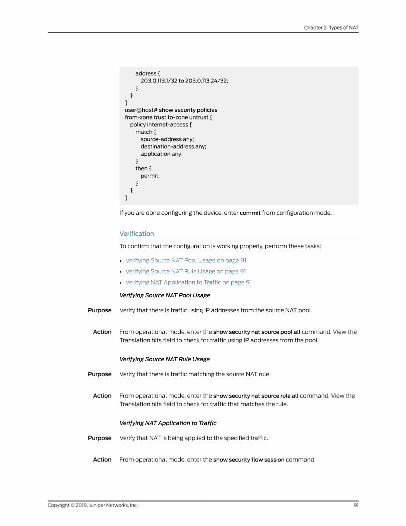
address {203.0.113.1/32 to 203.0.113.24/32;
}}
}user@host# show security policiesfrom-zone trust to-zone untrust {policy internet-access {match {source-address any;destination-address any;application any;
}then {permit;
}}
}
If you are done configuring the device, enter commit from configuration mode.
Verification
To confirm that the configuration is working properly, perform these tasks:
• Verifying Source NAT Pool Usage on page 91
• Verifying Source NAT Rule Usage on page 91
• Verifying NAT Application to Traffic on page 91
Verifying Source NAT Pool Usage
Purpose Verify that there is traffic using IP addresses from the source NAT pool.
Action From operational mode, enter the show security nat source pool all command. View the
Translation hits field to check for traffic using IP addresses from the pool.
Verifying Source NAT Rule Usage
Purpose Verify that there is traffic matching the source NAT rule.
Action From operational mode, enter the show security nat source rule all command. View the
Translation hits field to check for traffic that matches the rule.
Verifying NAT Application to Traffic
Purpose Verify that NAT is being applied to the specified traffic.
Action From operational mode, enter the show security flow session command.
91Copyright © 2018, Juniper Networks, Inc.
Chapter 2: Types of NAT

Understanding Source NAT PoolsWithout PAT
When you define a source pool, Junos OS enables PAT by default. To disable PAT, you
must specify no port translation when you are defining a source pool.
When using a source pool without PAT, Junos OS performs source Network Address
Translation for the IP address without performing PAT for the source port number. For
applications that require that a particular source port number remain fixed, youmust use
source pool without PAT.
The source pool can contain multiple IP addresses, multiple IP address ranges, or both.
For source pool without PAT, Junos OS assigns one translated source address to the
same host for all its concurrent sessions unless the address-pooling no-paired option is
enabled.
The number of hosts that a source NAT pool without PAT can support is limited to the
number of addresses in the pool. When you have a pool with a single IP address, only
one host can be supported, and traffic from other hosts is blocked because there are no
resources available. If a single IP address is configured for a source NAT pool without
PAT when NAT resource assignment is not in active-backupmode in a chassis cluster,
traffic through node 1 will be blocked.
Pool utilization for each source pool without PAT is computed. You can turn on pool
utilization alarm by configuring alarm thresholds. An SNMP trap is triggered every time
pool utilization rises above a threshold and goes below a threshold.
NOTE: If a static NAT rule is for one-to-one IP translation, avoid dividing therule intoadestination ruleandasource rulewhensourceno-patpoolwithoutaddress sharing is used. If you choose to divide the rule, you will then haveto use source pat-pool with single IP or source no-pat pool withmultiple IP.
Example: Configuring a Single IP Address in a Source NAT PoolWithout PAT
This exampledescribeshowtoconfigureaprivateaddressblock toasinglepublic address
in a source NAT pool without Port Address Translation.
NOTE: PAT is enabledbydefault for sourceNATpools.WhenPAT is disabled,thenumberof translations that thesourceNATpool canconcurrently supportis limited to thenumberofaddresses in thepool. Packetsaredropped if thereare no addresses available in the source NAT pool. However, using theaddress-shared option, you canmapmore that one private IP address to a
single public IP address as long as the traffic is from different source ports.
• Requirements on page 93
• Overview on page 93
Copyright © 2018, Juniper Networks, Inc.92
Network Address Translation Feature Guide for Security Devices
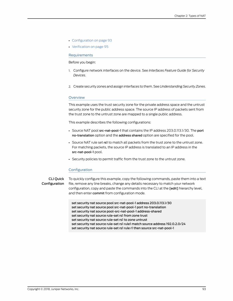
• Configuration on page 93
• Verification on page 95
Requirements
Before you begin:
1. Configure network interfaces on the device. See Interfaces Feature Guide for Security
Devices.
2. Create security zonesandassign interfaces to them.SeeUnderstandingSecurity Zones.
Overview
This example uses the trust security zone for the private address space and the untrust
security zone for the public address space. The source IP address of packets sent from
the trust zone to the untrust zone are mapped to a single public address.
This example describes the following configurations:
• Source NAT pool src-nat-pool-1 that contains the IP address 203.0.113.1/30. The port
no-translation option and the address shared option are specified for the pool.
• Source NAT rule set rs1 to match all packets from the trust zone to the untrust zone.
For matching packets, the source IP address is translated to an IP address in the
src-nat-pool-1 pool.
• Security policies to permit traffic from the trust zone to the untrust zone.
Configuration
CLI QuickConfiguration
To quickly configure this example, copy the following commands, paste them into a text
file, remove any line breaks, change any details necessary to match your network
configuration, copy and paste the commands into the CLI at the [edit] hierarchy level,
and then enter commit from configuration mode.
set security nat source pool src-nat-pool-1 address 203.0.113.1/30set security nat source pool src-nat-pool-1 port no-translationset security nat source pool-src-nat-pool-1 address-sharedset security nat source rule-set rs1 from zone trustset security nat source rule-set rs1 to zone untrustset security nat source rule-set rs1 rule1 match source address 192.0.2.0/24set security nat source rule-set rs1 rule r1 then source src-nat-pool-1
93Copyright © 2018, Juniper Networks, Inc.
Chapter 2: Types of NAT
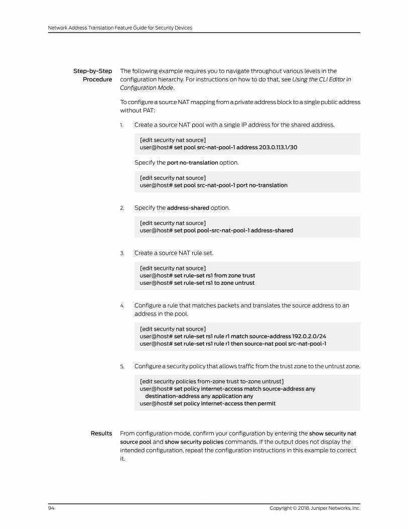
Step-by-StepProcedure
The following example requires you to navigate throughout various levels in the
configuration hierarchy. For instructions on how to do that, see Using the CLI Editor in
Configuration Mode.
ToconfigureasourceNATmapping fromaprivateaddressblock toasinglepublic address
without PAT:
1. Create a source NAT pool with a single IP address for the shared address.
[edit security nat source]user@host# set pool src-nat-pool-1 address 203.0.113.1/30
Specify the port no-translation option.
[edit security nat source]user@host# set pool src-nat-pool-1 port no-translation
2. Specify the address-shared option.
[edit security nat source]user@host# set pool pool-src-nat-pool-1 address-shared
3. Create a source NAT rule set.
[edit security nat source]user@host# set rule-set rs1 from zone trustuser@host# set rule-set rs1 to zone untrust
4. Configure a rule that matches packets and translates the source address to an
address in the pool.
[edit security nat source]user@host# set rule-set rs1 rule r1 match source-address 192.0.2.0/24user@host# set rule-set rs1 rule r1 then source-nat pool src-nat-pool-1
5. Configurea security policy that allows traffic fromthe trust zone to theuntrust zone.
[edit security policies from-zone trust to-zone untrust]user@host# set policy internet-accessmatch source-address anydestination-address any application any
user@host# set policy internet-access then permit
Results From configuration mode, confirm your configuration by entering the show security nat
source pool and show security policies commands. If the output does not display the
intended configuration, repeat the configuration instructions in this example to correct
it.
Copyright © 2018, Juniper Networks, Inc.94
Network Address Translation Feature Guide for Security Devices

[edit]user@host# show security natsource {pool src-nat-pool-1 {address {203.0.113.1/30
}port no-translation;
}address-shared;rule-set rs1 {from zone trust;to zone untrust;rule r1 {match {source-address [192.0.2.0/24]
}then {source-nat {pool {src-nat-pool-1;
}}
}}
}}user@host# show security policiesfrom-zone trust to-zone untrust {policy internet-access {match {source-address any;destination-address any;application any;
}then {permit;
}}
}
If you are done configuring the device, enter commit from configuration mode.
Verification
To confirm that the configuration is working properly, perform these tasks:
• Verifying Shared Address on page 95
• Verifying Shared Address Application to Traffic on page 96
Verifying Shared Address
Purpose Verify that two internal IP addresses, with different source ports, share one external IP
address.
95Copyright © 2018, Juniper Networks, Inc.
Chapter 2: Types of NAT
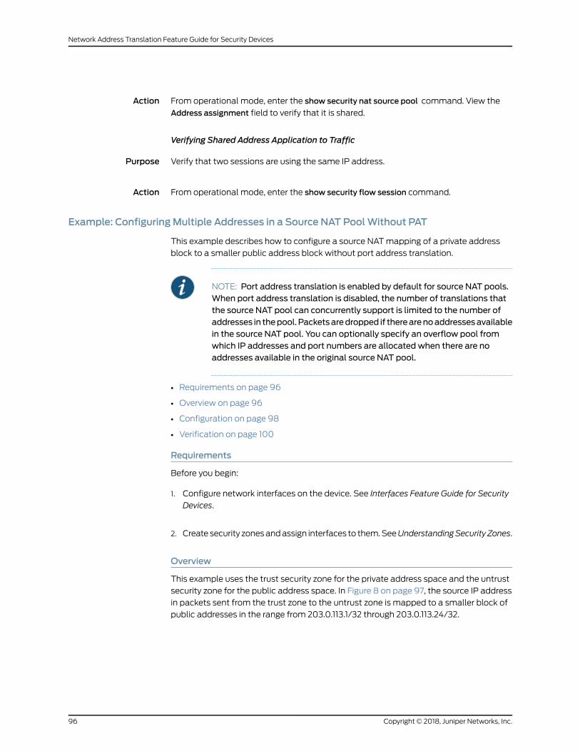
Action From operational mode, enter the show security nat source pool command. View the
Address assignment field to verify that it is shared.
Verifying Shared Address Application to Traffic
Purpose Verify that two sessions are using the same IP address.
Action From operational mode, enter the show security flow session command.
Example: ConfiguringMultiple Addresses in a Source NAT PoolWithout PAT
This example describes how to configure a source NATmapping of a private address
block to a smaller public address block without port address translation.
NOTE: Port address translation is enabled by default for source NAT pools.When port address translation is disabled, the number of translations thatthe source NAT pool can concurrently support is limited to the number ofaddresses in thepool.Packetsaredropped if therearenoaddressesavailablein the source NAT pool. You can optionally specify an overflow pool fromwhich IP addresses and port numbers are allocated when there are noaddresses available in the original source NAT pool.
• Requirements on page 96
• Overview on page 96
• Configuration on page 98
• Verification on page 100
Requirements
Before you begin:
1. Configure network interfaces on the device. See Interfaces Feature Guide for Security
Devices.
2. Create security zonesandassign interfaces to them.SeeUnderstandingSecurity Zones.
Overview
This example uses the trust security zone for the private address space and the untrust
security zone for the public address space. In Figure 8 on page 97, the source IP address
in packets sent from the trust zone to the untrust zone is mapped to a smaller block of
public addresses in the range from 203.0.113.1/32 through 203.0.113.24/32.
Copyright © 2018, Juniper Networks, Inc.96
Network Address Translation Feature Guide for Security Devices

Figure 8: Source NATMultiple AddressesWithout PAT
Trustzone
ge-0/0/0203.0.113.0/24SRX Series device
Untrustzone Internet
Public addressspace
Private addressspace
Original Source IP Translated Source IP
10.1.1.0/2410.1.2.0/24192.168.1.0/24
203.0.113.1 (no port address translation)
10.1.1.0/24 192.168.1.0/24
10.1.2.0/24
g030671
This example describes the following configurations:
• Source NAT pool src-nat-pool-1 that contains the IP address range 203.0.113.1/32
through 203.0.113.24/32. The port no-translation option is specified for the pool.
• Source NAT rule set rs1 to match all packets from the trust zone to the untrust zone.
For matching packets, the source IP address is translated to an IP address in the
src-nat-pool-1 pool.
• Proxy ARP for the addresses 203.0.113.1/32 through 203.0.113.24/32 on interface
ge-0/0/0.0. This allows the Juniper Networks security device to respond to ARP
requests received on the interface for those addresses.
• Security policies to permit traffic from the trust zone to the untrust zone.
97Copyright © 2018, Juniper Networks, Inc.
Chapter 2: Types of NAT

Configuration
CLI QuickConfiguration
To quickly configure this example, copy the following commands, paste them into a text
file, remove any line breaks, change any details necessary to match your network
configuration, copy and paste the commands into the CLI at the [edit] hierarchy level,
and then enter commit from configuration mode.
set security nat source pool src-nat-pool-1 address 203.0.113.1/32 to 203.0.113.24/32set security nat source pool src-nat-pool-1 port no-translationset security nat source rule-set rs1 from zone trustset security nat source rule-set rs1 to zone untrustset security nat source rule-set rs1 rule r1 match source-address 0.0.0.0/0set security nat source rule-set rs1 rule r1 match destination-address 0.0.0.0/0set security nat source rule-set rs1 rule r1 then source-nat pool src-nat-pool-1set securitynatproxy-arp interfacege-0/0/0.0address203.0.113.1/32 to203.0.113.24/32set security policies from-zone trust to-zone untrust policy internet-accessmatchsource-address any
set security policies from-zone trust to-zone untrust policy internet-accessmatchdestination-address any
set security policies from-zone trust to-zone untrust policy internet-accessmatchapplication any
set security policies from-zone trust to-zone untrust policy internet-access then permit
Step-by-StepProcedure
The following example requires you to navigate throughout various levels in the
configuration hierarchy. For instructions on how to do that, see Using the CLI Editor in
Configuration Mode.
To configure a source NATmapping from a private address block to a smaller public
address block without PAT:
1. Create a source NAT pool.
[edit security nat source]user@host# set pool src-nat-pool-1 address 203.0.113.1 to 203.0.113.24
2. Specify the port no-translation option.
[edit security nat source]user@host# set pool src-nat-pool-1 port no-translation
3. Create a source NAT rule set.
[edit security nat source]user@host# set rule-set rs1 from zone trustuser@host# set rule-set rs1 to zone untrust
4. Configure a rule that matches packets and translates the source address to an
address in the pool.
Copyright © 2018, Juniper Networks, Inc.98
Network Address Translation Feature Guide for Security Devices

[edit security nat source]user@host# set rule-set rs1 rule r1 match source-address 0.0.0.0/0user@host# set rule-set rs1 rule r1 match destination-address 0.0.0.0/0user@host# set rule-set rs1 rule r1 then source-nat pool src-nat-pool-1
5. Configure proxy ARP.
[edit security nat]user@host# set proxy-arp interface ge-0/0/0.0 address 203.0.113.1 to 203.0.113.24
6. Configurea security policy that allows traffic fromthe trust zone to theuntrust zone.
[edit security policies from-zone trust to-zone untrust]user@host# set policy internet-accessmatch source-address anydestination-address any application any
user@host# set policy internet-access then permit
Results From configuration mode, confirm your configuration by entering the show security nat
and show security policies commands. If the output does not display the intended
configuration, repeat the configuration instructions in this example to correct it.
[edit]user@host# show security natsource {pool src-nat-pool-1 {address {203.0.113.1/32 to 203.0.113.24/32;
}port no-translation;
}rule-set rs1 {from zone trust;to zone untrust;rule r1 {match {source-address 0.0.0.0/0;destination-address 0.0.0.0/0;
}then {source-nat {pool {src-nat-pool-1;
}}
}}
}}proxy-arp {interface ge-0/0/0.0 {
99Copyright © 2018, Juniper Networks, Inc.
Chapter 2: Types of NAT
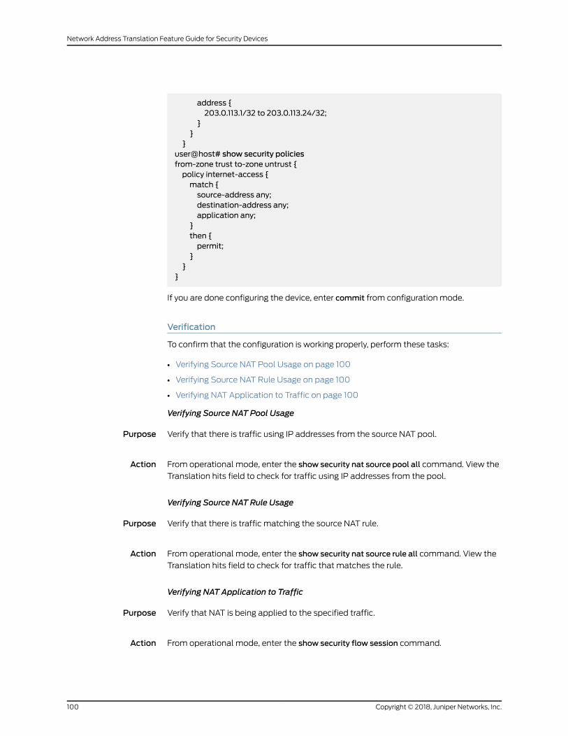
address {203.0.113.1/32 to 203.0.113.24/32;
}}
}user@host# show security policiesfrom-zone trust to-zone untrust {policy internet-access {match {source-address any;destination-address any;application any;
}then {permit;
}}
}
If you are done configuring the device, enter commit from configuration mode.
Verification
To confirm that the configuration is working properly, perform these tasks:
• Verifying Source NAT Pool Usage on page 100
• Verifying Source NAT Rule Usage on page 100
• Verifying NAT Application to Traffic on page 100
Verifying Source NAT Pool Usage
Purpose Verify that there is traffic using IP addresses from the source NAT pool.
Action From operational mode, enter the show security nat source pool all command. View the
Translation hits field to check for traffic using IP addresses from the pool.
Verifying Source NAT Rule Usage
Purpose Verify that there is traffic matching the source NAT rule.
Action From operational mode, enter the show security nat source rule all command. View the
Translation hits field to check for traffic that matches the rule.
Verifying NAT Application to Traffic
Purpose Verify that NAT is being applied to the specified traffic.
Action From operational mode, enter the show security flow session command.
Copyright © 2018, Juniper Networks, Inc.100
Network Address Translation Feature Guide for Security Devices

Understanding Shared Addresses in Source NAT Pools without PAT
SourceNATpoolswith no port address translation perform static, one-to-onemappings
from one source IP address to one external IP address. When there is only one external
IP address, or very few available in a source no-pat pool , the address-shared option
enables you to mapmany source IP addresses to one external IP address as long as the
traffic comes from different source ports.
For example, if there is a source NAT pool with no port translation containing only two
IP addresses, IP 1 and IP 2, when a packet arrives from
1. Source IP 1, port 1, it is translated to IP 1, port 1.
2. Source IP 2, port 2, it is translated to IP 2, port 2.
3. Source IP 3, port 1, it is translated to IP 2, port 1. (It cannot be translated to IP 1 port 1
because that port is already used.
However, if another packet arrives from Source IP 3, port 1 for a different destination
IP and port, it cannot be translated to IP 1, port 1 or IP 2, port 1 because port 1 is already
used for both available IP addresses. The session will fail.
This option increasesNAT resources and improves thepossibility of setting up successful
translated traffic. It cannot be used on source NAT pools with port address translation
because address sharing is already their default behavior.
Understanding NAT Session Persistence
Network Address Translation (NAT) session persistence provides ameans to retain
existing sessions, instead of clearing them,when there changes in theNAT configuration.
If session persistence is enabled, the retained sessions continue to process and forward
packets as timeand resources are optimally used to rebuild the impacted sessions. Thus,
packet forwarding does not stop even if the NAT configuration is changed for some or
all sessions.
From Junos OS Release 18.3R1 onward, with the support for NAT session persistence,
the Packet Forwarding Engine scans the sessions and decides whether to keep the
sessions or clear the sessions. In releases before Junos OS Release 18.3R1, the NAT
sessions are cleared if there is a change in the NAT configuration.
The Packet Forwarding Engine performs the following two types of scans to decide
whether to retain or drop sessions:
• SourceNATpool sessionpersistencescan—ThePacket Forwarding Engine comparesthe existing session IP address with source pool address range. If the existing session
IP address is in the specified source pool address range, the session is kept alive,
otherwise the session is cleared.
• Source NAT rule session persistence scan—The Packet Forwarding Engine uses therule ID to compare the source IP address, source port, destination IP address, and
101Copyright © 2018, Juniper Networks, Inc.
Chapter 2: Types of NAT

destination port between the old and new configurations. If the new and old
configurations are the same, then the session is kept alive, otherwise the session is
cleared.
NOTE:
• NAT session persistence is not supported for static NAT and destinationNAT.
• NATsession persistence is not supported if thePATpool is configuredwiththe address persistent, address pooling paired, source address-persistent,portblockallocation,portdeterministic,persistentnat,andportoverloadingfactor fields.
NAT session persistence is supported only for source NAT in the following scenarios:
• Source pool—Change in an address range in a Port Address Translation (PAT) pool.
• Source rule—Change inmatchconditions for theaddressbook, application, destination
IP address, destination port, source IP address, and destination port information.
To enable the NAT session persistence scanning, include the session-persistence-scan
statement at the [edit security nat source] hierarchy level.
You canalso configure a timeout value to retain the sessions for the specified timeperiod
by using the set security nat source session-drop-hold-down CLI command. The value of
thesession-drop-hold-downoption ranges from30through28,800seconds(eighthours).
The session expires after the configured timeout period.
• Limitations of NAT Session Persistence on page 102
Limitations of NAT Session Persistence
• When there is a change in IP addresses in the NAT source pool, the newly configured
IP addresses are appended to theNATsourcepool. After theNATsourcepool is rebuilt,
the new IP addresses are not the same as the existing IP addresses. The differences
in the IP addresses in the NAT source pool impacts the round-robin mode of picking
IP addresses from the NAT source pool.
• If the scan types identify sessions that will never be timed out (that is, the sessions for
which the session-drop-hold-down value is not configured or is configured as 8 hours),
then thePacketForwardingEngine ignores thosesessions, and thesessionsare retained.
Configuring the NAT Session Hold Timeout and NAT Session Persistence Scan
This configurationshowshowtoconfigure theNATsessionhold timeoutandNATsession
persistence.
Configuring NAT Session Hold Timeout
The following configuration shows how to configure the NAT session hold timeout.
Copyright © 2018, Juniper Networks, Inc.102
Network Address Translation Feature Guide for Security Devices

• To set the NAT session hold timeout period:
[edit security nat source]user@host# set session-drop-hold-down time;
The value of the time variable ranges from 30 through 28,800 seconds (eight hours).
The session expires after the configured timeout period.
Results
From configuration mode, confirm your configuration by entering the show securitycommand. If the output does not display the intended configuration, repeat theconfiguration instructions in this example to correct it.
[edit]user@host# show securitynat {source {session-drop-hold-down 28800;
}}
Configuring NAT Session Persistence Scan
The following configuration shows how to configure the NAT session persistence scan.
• To enable the NAT session persistence scan:
[edit security nat source]user@host# set session-persistence-scan
Results
From configuration mode, confirm your configuration by entering the show securitycommand. If the output does not display the intended configuration, repeat theconfiguration instructions in this example to correct it.
[edit]user@host# show securitynat {source {session-persistence-scan;
}}
Understanding NAT Configuration Check on Egress Interfaces after Reroute
The Network Address Translation (NAT) configuration often changes to accommodate
more users and to enhance shortest route to transfer the traffic. If there is a change in
egress interface because of rerouting of traffic, you can use the set security flow
103Copyright © 2018, Juniper Networks, Inc.
Chapter 2: Types of NAT

enable-reroute-uniform-link-checknat command to retain the existingNAT configuration
and rule.
When the enable-reroute-uniform-link-check nat command is enabled:
• The session is retained with the existing NAT rule, if the new egress interface and the
previous egress interface are in the same security zone, and there is no change in the
matched NAT rule or if no rule is applied before and after rerouting.
• The session expires if the new egress interface and the previous egress interface are
in the same security zone and thematched NAT rule is changed.
When the enable-reroute-uniform-link-check nat command is disabled:
• The traffic is forwarded to the new egress interface if the new egress interface and the
previous egress interface are in the same security zone.
Copyright © 2018, Juniper Networks, Inc.104
Network Address Translation Feature Guide for Security Devices

Configuration
To enable the NAT configuration for an existing session when there is a change in egress
interface because of rerouting, use the following command:
[edit]
user@host# set security flow enable-reroute-uniform-link-check nat
The new configuration is applied when you commit the configuration changes.
The enable-reroute-uniform-link-check nat command is disabled by default.
Limitations
Retaining the NAT configuration using the set security flow
enable-reroute-uniform-link-check nat command has the following limitations:
• The TCP synchronization does not allow the new session to transfer the traffic. You
must disable the TCP synchronization to allow the transfer of traffic in new sessions.
• The packet information might lost if reroute is initiated after a three-way handshake
to initialize communication. Youmust disable the Junos OS Services Framework (JSF)
like Application Layer Gateway (ALG) to allow the transfer of traffic in new sessions.
Release History Table DescriptionRelease
Starting in Junos OS Release 17.4R1, source NAT resources handled by thecentral point architecture have been offloaded to the SPUs when the SPCnumber is more than four, resulting in more efficient resource allocation.
17.4R1
Starting in Junos OS Release 15.1X49-D30 and Junos OS Release 17.3R1, thecentral point architecture for NAT has been enhanced to handle higher systemsession capacity and session ramp-up rate for the SRX5000 line.
15.1X49-D30
In Release 12.3X48-D40, and in Release 15.1X49-D60 and later releases, youcan increase the source NAT port capacity to 2.4G on SRX5400, SRX5600,and SRX5800deviceswith next-generation Services Processing Cards (SPCs)using the port-scaling-enlargement statement at the [edit security natsource] hierarchy level supported
12.3X48-D40
Destination NAT
DestinationNAT changes the destination address of packets passing through theRouter.
It also offers the option to perform the port translation in the TCP/UDP headers.
Destination NATmainly used to redirect incoming packets with an external address or
port destination to an internal IP address or port inside the network.
• Understanding Destination NAT on page 106
• Understanding Destination NAT Address Pools on page 106
• Understanding Destination NAT Rules on page 107
• Destination NAT Configuration Overview on page 108
105Copyright © 2018, Juniper Networks, Inc.
Chapter 2: Types of NAT

• Example: Configuring Destination NAT for Single Address Translation on page 108
• Example: Configuring Destination NAT for IP Address and Port Translation on page 115
• Example: Configuring Destination NAT for Subnet Translation on page 121
• Monitoring Destination NAT Information on page 127
Understanding Destination NAT
Destination NAT is the translation of the destination IP address of a packet entering the
Juniper Networks device. Destination NAT is used to redirect traffic destined to a virtual
host (identified by the original destination IP address) to the real host (identified by the
translated destination IP address).
NOTE: When destination NAT is performed, the destination IP address istranslated according to configured destination NAT rules and then securitypolicies are applied.
Destination NAT allows connections to be initiated only for incoming network
connections—for example, from the Internet to a private network. Destination NAT is
commonly used to perform the following actions:
• Translate a single IP address to another address (for example, to allow a device on
the Internet to connect to a host on a private network).
• Translate a contiguous block of addresses to another block of addresses of the same
size (for example, to allow access to a group of servers).
• Translate a destination IP address and port to another destination IP address and port
(for example, to allow access to multiple services using the same IP address but
different ports).
The following types of destination NAT are supported:
• Translation of the original destination IP address to an IP address from a user-defined
pool. This type of translation does not include Port Address Translation (PAT). If the
original destination IPaddress range is larger than theaddress range in theuser-defined
address pool, any untranslated packets are dropped.
• Translation of the original destination IP address (and optional port number) to one
specific IP address (and port number) from a user-defined pool.
Understanding Destination NAT Address Pools
A NAT pool is a user-defined set of IP addresses that are used for translation. Unlike
static NAT, where there is a one-to-onemapping that includes destination IP address
translation in one direction and source IP address translation in the reverse direction,
with destination NAT, you translate the original destination address to an IP address in
the address pool.
For destination NAT address pools, specify the following:
Copyright © 2018, Juniper Networks, Inc.106
Network Address Translation Feature Guide for Security Devices

• Name of the destination NAT address pool
• Destination address or address range
NOTE: Do not overlap NAT addresses for source NAT, destination NAT,and static NATwithin one routing instance.
• Destination port that is used for port forwarding
• Routing instance to which the pool belongs—A destination NAT pool that does not
specify a specific routing instance will default to the routing instance of the ingress
zone.
NOTE: YoucanconfigureaNATpool toexist in thedefault routing instance.Configuration option to specify that a NAT pool exists in the defaultrouting-instance is available. As a result, the NAT pool is reachable fromzones in the default routing instance, and from zones in other routinginstances.
Understanding Destination NAT Rules
Destination NAT rules specify two layers of match conditions:
• Traffic direction—Allows you to specify from interface, from zone, or from
routing-instance.
• Packet information—Can be source IP addresses, destination IP address or subnet,
destination port numbers or port ranges, protocols, or applications.
For ALG traffic, we recommend that you not use the destination-port option or the
application option asmatching conditions. If these options are used, translationmay fail
because the port value in the application payloadmight not match the port value in the
IP address.
If multiple destination NAT rules overlap in the match conditions, the most specific rule
is chosen. For example, if rules A and B specify the same source and destination IP
addresses, but ruleAspecifies traffic fromzone 1and ruleBspecifies traffic from interface
ge-0/0/0, rule B is used to perform destination NAT. An interface match is considered
to bemore specific than a zonematch, which is more specific than a routing instance
match.
The actions you can specify for a destination NAT rule are:
• off—Do not perform destination NAT.
• pool—Use the specified user-defined address pool to perform destination NAT.
Destination NAT rules are applied to traffic in the first packet that is processed for the
flow or in the fast path for the ALG. Destination NAT rules are processed after static NAT
rules but before source NAT rules.
107Copyright © 2018, Juniper Networks, Inc.
Chapter 2: Types of NAT

Destination NAT Configuration Overview
Themain configuration tasks for destination NAT are as follows:
1. Configure a destination NAT address pool that aligns with your network and security
requirements.
2. ConfiguredestinationNAT rules thatalignwithyournetworkandsecurity requirements.
3. Configure NAT proxy ARP entries for IP addresses in the same subnet of the ingress
interface.
Example: Configuring Destination NAT for Single Address Translation
This example describes how to configure a destination NATmapping of a single public
address to a private address.
NOTE: Mapping one destination IP address to another can also beaccomplished with static NAT. Static NATmapping allows connections tobe established from either side of the gateway device, whereas destinationNATonlyallowsconnections tobeestablished fromoneside.However, staticNATonly allows translations fromone address to another or between blocksof addresses of the same size.
• Requirements on page 108
• Overview on page 108
• Configuration on page 110
• Verification on page 112
Requirements
This example uses the following hardware and software components:
• SRX Series device
• Server
Before you begin:
• Configurenetwork interfaceson thedevice. See the Interfaces FeatureGuide for Security
Devices.
• Create security zones andassign interfaces to them.SeeUnderstandingSecurity Zones.
Overview
Destination NAT is commonly used to distribute a service located in a private network
with a publicly accessible IP address. This allows users to use the private service with
Copyright © 2018, Juniper Networks, Inc.108
Network Address Translation Feature Guide for Security Devices

the public IP address. Destination NAT address pool and destination NAT rules
configurations are used to align your network and improve security requirements.
In this example, first you configure the trust security zone for the private address space
and then you configure the untrust security zone for the public address space. In
Figure 9 on page 109, devices in the untrust zone access a server in the trust zone byway
of public address 3.0.113.200/32. For packets that enter the Juniper Networks security
device from the untrust zone with the destination IP address 203.0.113.200/32, the
destination IP address is translated to the private address 192.168.1.200/32.
Topology
Figure 9: Destination NAT Single Address Translation
Server192.168.1.200
Trustzone
ge-0/0/0203.0.113.0/24
ge-1/0/0192.168.1.0/24
SRX Series device
Untrustzone Internet
Public addressspace
Private addressspace
Original Destination IP Translated Destination IP
203.0.113.200/32 192.168.1.200/32
g030665
Table 8 on page 110 shows the parameters configured in this example.
109Copyright © 2018, Juniper Networks, Inc.
Chapter 2: Types of NAT

Table 8: Interfaces, Zones, Server, and IP Address Information
DescriptionParameter
Security zone for the private address space.Trust Zone
Security zone for the public address space.Untrust Zone
Translated destination NAT IP address.192.168.1.200/32
Private subnet in private zone.192.168.1.0/24
Public address of the server.203.0.113.200/32
Server address of the private address space.Server
NAT interfaces for traffic direction.ge-0/0/0 and ge-1/0/0
This example describes the following configurations:
• Destination NAT pool dst-nat-pool-1 that contains the IP address 192.168.1.200/32.
• DestinationNAT rule set rs1with rule r1 tomatch packets received from the ge-0/0/0.0
interface with the destination IP address 203.0.113.200/32. For matching packets, the
destination address is translated to the address in the dst-nat-pool-1 pool.
• Proxy ARP for the address 203.0.113.200/32 on interface ge-0/0/0.0. This allows the
Juniper Networks security device to respond to ARP requests received on the interface
for that address.
• Security policies to permit traffic from the untrust zone to the translated destination
IP address in the trust zone.
Configuration
CLI QuickConfiguration
To quickly configure this example, copy the following commands, paste them into a text
file, remove any line breaks, change any details necessary to match your network
configuration, copy and paste the commands into the CLI at the [edit] hierarchy level,
and then enter commit from configuration mode.
set security nat destination pool dst-nat-pool-1 address 192.168.1.200/32set security nat destination rule-set rs1 from interface ge-0/0/0.0setsecuritynatdestination rule-set rs1 rule r1matchdestination-address203.0.113.200/32set security nat destination rule-set rs1 rule r1 then destination-nat pool dst-nat-pool-1set security nat proxy-arp interface ge-0/0/0.0 address 203.0.113.200/32set security address-book global address server-1 192.168.1.200/32set security policies from-zone untrust to-zone trust policy server-accessmatchsource-address any
set security policies from-zone untrust to-zone trust policy server-accessmatchdestination-address server-1
setsecuritypoliciesfrom-zoneuntrustto-zonetrustpolicyserver-accessmatchapplicationany
Copyright © 2018, Juniper Networks, Inc.110
Network Address Translation Feature Guide for Security Devices

set security policies from-zone untrust to-zone trust policy server-access then permit
Step-by-StepProcedure
The following example requires you to navigate various levels in the configuration
hierarchy. For instructions on how to do that, see Using the CLI Editor in Configuration
Mode in the CLI User Guide.
To configure a destination NATmapping from a public address to a private address:
1. Create the destination NAT pool.
[edit security nat destination]user@host# set pool dst-nat-pool-1 address 192.168.1.200/32
2. Create a destination NAT rule set.
[edit security nat destination]user@host# set rule-set rs1 from interface ge-0/0/0.0
3. Configure a rule that matches packets and translates the destination address to
the address in the pool.
[edit security nat destination]user@host# set rule-set rs1 rule r1 match destination-address 203.0.113.200/32user@host# set rule-set rs1 rule r1 then destination-nat pool dst-nat-pool-1
4. Configure proxy ARP.
[edit security nat]user@host# set proxy-arp interface ge-0/0/0.0 address 203.0.113.200/32
5. Configure an address in the global address book.
[edit security address-book global]user@host# set address server-1 192.168.1.200/32
6. Configure a security policy that allows traffic from the untrust zone to the server in
the trust zone.
[edit security policies from-zone untrust to-zone trust]user@host# set policy server-accessmatch source-address anyuser@host# set policy server-accessmatch destination-address server-1user@host# set policy server-accessmatch application anyuser@host# set policy server-access then permit
Results From configuration mode, confirm your configuration by entering the show interfaces,
show security zones, and show bridge-domains command. If the output does not display
111Copyright © 2018, Juniper Networks, Inc.
Chapter 2: Types of NAT

the intended configuration, repeat the instructions in this example to correct the
configuration.
[edit]user@host# show security natdestination {pool dst-nat-pool-1 {address 192.168.1.200/32;
}rule-set rs1 {from interface ge-0/0/0.0;rule r1 {match {destination-address 203.0.113.200/32;
}then {destination-nat pool dst-nat-pool-1;
}}
}}proxy-arp {interface ge-0/0/0.0 {address {203.0.113.200/32;
}}
}[edit]user@host# show security address-bookglobal {address server-1 192.168.1.200/32;
}user@host# show security policiesfrom-zone untrust to-zone trust {policy server-access {match {source-address any;destination-address server-1;application any;
}then {permit;
}}
If you are done configuring the device, enter commit from configuration mode.
Verification
Confirm that the configuration is working properly.
• Verifying Destination NAT Pool Usage on page 113
• Verifying Destination NAT Rule Usage on page 113
Copyright © 2018, Juniper Networks, Inc.112
Network Address Translation Feature Guide for Security Devices

• Verifying Destination NAT for a Single Address Translation on page 114
• Verifying NAT Application to Traffic on page 114
Verifying Destination NAT Pool Usage
Purpose Verify that there is traffic using IP addresses from the destination NAT pool.
Action From operational mode, enter the show security nat destination pool all command. View
the Translation hits field to check for traffic using IP addresses from the pool.
user@host>show security nat destination pool all
Total destination-nat pools: 1
Pool name : dst-nat-pool-1Pool id : 1Total address : 1Translation hits: 71Address range Port 192.168.1.200 - 192.168.1.200 0
Meaning The show security nat destination pool all command displays the pool of translated
addresses. View the Translation hits field to check for traffic using IP addresses from the
pool.
Verifying Destination NAT Rule Usage
Purpose Verify that there is traffic matching the destination NAT rule.
Action From operational mode, enter the show security nat destination rule all command.
user@host>show security nat destination rule all
Total destination-nat rules: 1Total referenced IPv4/IPv6 ip-prefixes: 1/0
Destination NAT rule: r1 Rule-set: rs1 Rule-Id : 1 Rule position : 1 From interface : ge-0/0/0.0 Destination addresses : 203.0.113.200 - 203.0.113.200 Action : dst-nat-pool-1 Translation hits : 75 Successful sessions : 75 Failed sessions : 0 Number of sessions : 4
Meaning The show security nat destination rule all command displays the destination NAT rule.
View the Translation hits field to check for traffic that matches the destination rule.
113Copyright © 2018, Juniper Networks, Inc.
Chapter 2: Types of NAT

Verifying Destination NAT for a Single Address Translation
Purpose Verify the configuration of destination NAT for a single address translation.
Action From operational mode, enter the show security nat destination summary command.
user@host>show security nat destination summary
Total pools: 1Pool name Address Range Routing Port Total Instance Addressdst-nat-pool-1 192.168.1.200 - 192.168.1.200 0 1
Total rules: 1Rule name Rule set From Actionr1 rs1 ge-0/0/0.0 dst-nat-pool-1
Meaning The show security nat destination summary command displays information about
destination NAT configuration. You can verify the following information:
• Rule sets
• Rules
• Address range
• NAT pool
• Port details
Verifying NAT Application to Traffic
Purpose Verify that NAT is being applied to the specified traffic.
Action From operational mode, enter the show security flow session command.
user@host>show security flow session
Session ID: 26415, Policy name: server-access/11, Timeout: 2, Valid In: 203.0.113.219/30 --> 203.0.113.200/54850;icmp, If: ge-0/0/0.0, Pkts: 1, Bytes: 84 Out: 192.168.1.200/54850 --> 203.0.113.219/30;icmp, If: ge-0/0/1.0, Pkts: 1, Bytes: 84
Session ID: 26420, Policy name: server-access/11, Timeout: 2, Valid In: 203.0.113.219/31 --> 203.0.113.200/54850;icmp, If: ge-0/0/0.0, Pkts: 1, Bytes: 84 Out: 192.168.1.200/54850 --> 203.0.113.219/31;icmp, If: ge-0/0/1.0, Pkts: 1, Bytes: 84
Session ID: 26425, Policy name: server-access/11, Timeout: 4, Valid In: 203.0.113.219/32 --> 203.0.113.200/54850;icmp, If: ge-0/0/0.0, Pkts: 1, Bytes: 84 Out: 192.168.1.200/54850 --> 203.0.113.219/32;icmp, If: ge-0/0/1.0, Pkts: 1,
Copyright © 2018, Juniper Networks, Inc.114
Network Address Translation Feature Guide for Security Devices

Bytes: 84
Session ID: 26431, Policy name: server-access/11, Timeout: 4, Valid In: 203.0.113.219/33 --> 203.0.113.200/54850;icmp, If: ge-0/0/0.0, Pkts: 1, Bytes: 84 Out: 192.168.1.200/54850 --> 203.0.113.219/33;icmp, If: ge-0/0/1.0, Pkts: 1, Bytes: 84Total sessions: 9
Meaning The showsecurity flowsession commanddisplaysactive sessionson thedeviceandeach
session’s associated security policy. The output shows traffic entering the device using
the private source address 203.0.113.219/30 destined to a public host at 203.0.113.200.
The return traffic from this flow travels to the translated public address 203.0.113.219.
• Session ID—Number that identifies the session. Use this ID to get more informationabout the session such as policy name or number of packets in and out.
• server-access—Policy name that permitted the traffic from the untrust zone to the
translated destination IP address in the trust zone.
• In—Incoming flow (source and destination IP addresses with their respective source
and destination port numbers, the session is ICMP, and the source interface for this
session is ge-0/0/0.0).
• Out—Reverse flow (source and destination IP addresses with their respective source
and destination port numbers, the session is ICMP, and the destination interface for
this session is ge-0/0/1.0).
Example: Configuring Destination NAT for IP Address and Port Translation
This example describes how to configure destination NATmappings of a public address
to private addresses, depending on the port number.
• Requirements on page 115
• Overview on page 116
• Configuration on page 118
• Verification on page 121
Requirements
Before you begin:
1. Configure network interfaces on the device. See Interfaces Feature Guide for Security
Devices.
2. Create security zonesandassign interfaces to them.SeeUnderstandingSecurity Zones.
115Copyright © 2018, Juniper Networks, Inc.
Chapter 2: Types of NAT
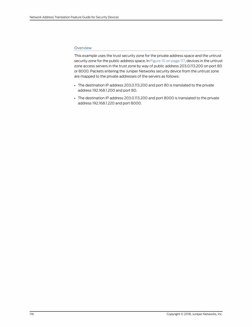
Overview
This example uses the trust security zone for the private address space and the untrust
security zone for the public address space. In Figure 10 on page 117, devices in the untrust
zone access servers in the trust zone by way of public address 203.0.113.200 on port 80
or 8000. Packets entering the Juniper Networks security device from the untrust zone
are mapped to the private addresses of the servers as follows:
• The destination IP address 203.0.113.200 and port 80 is translated to the private
address 192.168.1.200 and port 80.
• The destination IP address 203.0.113.200 and port 8000 is translated to the private
address 192.168.1.220 and port 8000.
Copyright © 2018, Juniper Networks, Inc.116
Network Address Translation Feature Guide for Security Devices

Figure 10: Destination NAT Address and Port Translation
Server192.168.1.220
Trustzone
ge-0/0/0203.0.113.0/24
ge-1/0/0192.168.1.0/24
SRX Series device
Untrustzone Internet
Public addressspace
Private addressspace
Original Destination IP Translated Destination IP
203.0.113.200port 80
192.168.1.200port 80
Server192.168.1.200
203.0.113.200port 8000
192.168.1.220port 8000
g030666
This example describes the following configurations:
• Destination NAT pool dst-nat-pool-1 that contains the IP address 192.168.1.200 port
80.
• Destination NAT pool dst-nat-pool-2 that contains the IP address 192.168.1.220 and
port 8000.
117Copyright © 2018, Juniper Networks, Inc.
Chapter 2: Types of NAT

• Destination NAT rule set rs1with rule r1 to match packets received from the untrust
zone with the destination IP address 203.0.113.200 and destination port 80. For
matching packets, the destination address is translated to the address in the
dst-nat-pool-1 pool.
• Destination NAT rule set rs1with rule r2 to match packets received from the untrust
zone with the destination IP address 203.0.113.200 and destination port 8000. For
matching packets, the destination IP address and port are translated to the address
and port in the dst-nat-pool-2 pool.
• Proxy ARP for the address 203.0.113.200/32. This allows the Juniper Networks security
device to respond to ARP requests received on the interface for that address.
• Security policies to permit traffic from the untrust zone to the translated destination
IP addresses in the trust zone.
Configuration
CLI QuickConfiguration
To quickly configure this example, copy the following commands, paste them into a text
file, remove any line breaks, change any details necessary to match your network
configuration, copy and paste the commands into the CLI at the [edit] hierarchy level,
and then enter commit from configuration mode.
set security nat destination pool dst-nat-pool-1 address 192.168.1.200/32set security nat destination pool dst-nat-pool-1 address port 80set security nat destination pool dst-nat-pool-2 address 192.168.1.220/32set security nat destination pool dst-nat-pool-2 address port 8000set security nat destination rule-set rs1 from zone untrustsetsecuritynatdestination rule-set rs1 rule r1matchdestination-address203.0.113.200/32set security nat destination rule-set rs1 rule r1 match destination-port 80set security nat destination rule-set rs1 rule r1 then destination-nat pool dst-nat-pool-1setsecuritynatdestination rule-set rs1 rule r2matchdestination-address203.0.113.200/32set security nat destination rule-set rs1 rule r2match destination-port 8000set security nat destination rule-set rs1 rule r2 then destination-nat pool dst-nat-pool-2set security nat proxy-arp interface ge-0/0/0.0 address 203.0.113.200/32set security address-book global address server-2 192.168.1.220/32set security address-book global address server-1 192.168.1.200/32set security policies from-zone untrust to-zone trust policy server-accessmatchsource-address any
set security policies from-zone untrust to-zone trust policy server-accessmatchdestination-address server-1
set security policies from-zone untrust to-zone trust policy server-accessmatchdestination-address server-2
setsecuritypoliciesfrom-zoneuntrustto-zonetrustpolicyserver-accessmatchapplicationany
set security policies from-zone untrust to-zone trust policy server-access then permit
Copyright © 2018, Juniper Networks, Inc.118
Network Address Translation Feature Guide for Security Devices
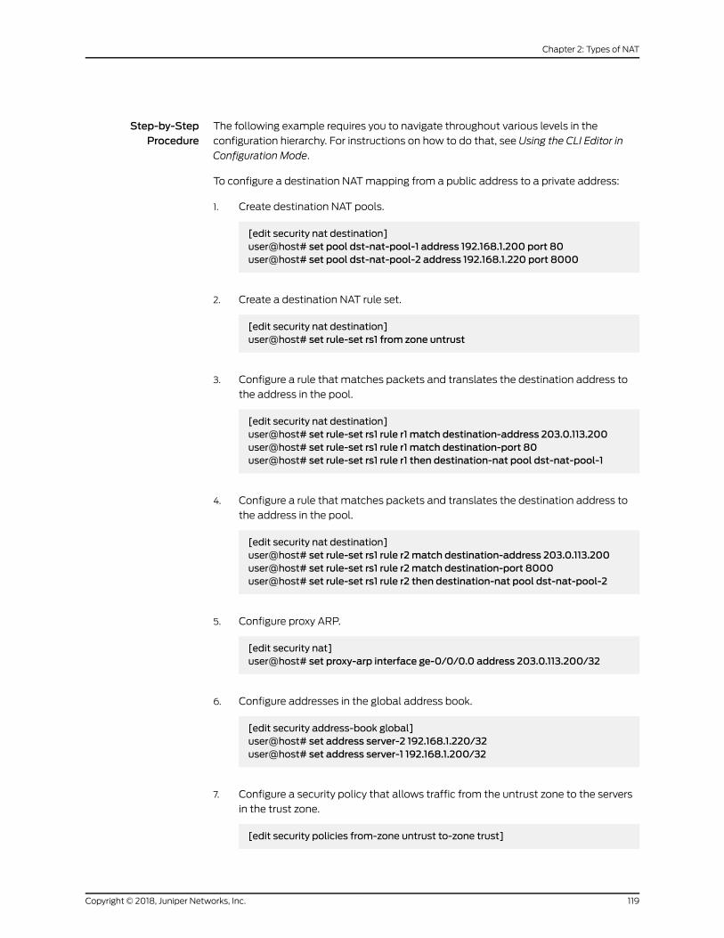
Step-by-StepProcedure
The following example requires you to navigate throughout various levels in the
configuration hierarchy. For instructions on how to do that, see Using the CLI Editor in
Configuration Mode.
To configure a destination NATmapping from a public address to a private address:
1. Create destination NAT pools.
[edit security nat destination]user@host# set pool dst-nat-pool-1 address 192.168.1.200 port 80user@host# set pool dst-nat-pool-2 address 192.168.1.220 port 8000
2. Create a destination NAT rule set.
[edit security nat destination]user@host# set rule-set rs1 from zone untrust
3. Configure a rule that matches packets and translates the destination address to
the address in the pool.
[edit security nat destination]user@host# set rule-set rs1 rule r1 match destination-address 203.0.113.200user@host# set rule-set rs1 rule r1 match destination-port 80user@host# set rule-set rs1 rule r1 then destination-nat pool dst-nat-pool-1
4. Configure a rule that matches packets and translates the destination address to
the address in the pool.
[edit security nat destination]user@host# set rule-set rs1 rule r2match destination-address 203.0.113.200user@host# set rule-set rs1 rule r2match destination-port 8000user@host# set rule-set rs1 rule r2 then destination-nat pool dst-nat-pool-2
5. Configure proxy ARP.
[edit security nat]user@host# set proxy-arp interface ge-0/0/0.0 address 203.0.113.200/32
6. Configure addresses in the global address book.
[edit security address-book global]user@host# set address server-2 192.168.1.220/32user@host# set address server-1 192.168.1.200/32
7. Configure a security policy that allows traffic from the untrust zone to the servers
in the trust zone.
[edit security policies from-zone untrust to-zone trust]
119Copyright © 2018, Juniper Networks, Inc.
Chapter 2: Types of NAT
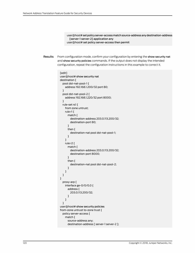
user@host#setpolicyserver-accessmatchsource-addressanydestination-address[server-1 server-2] application any
user@host# set policy server-access then permit
Results From configuration mode, confirm your configuration by entering the show security nat
and show security policies commands. If the output does not display the intended
configuration, repeat the configuration instructions in this example to correct it.
[edit]user@host# show security natdestination {pool dst-nat-pool-1 {address 192.168.1.200/32 port 80;
}pool dst-nat-pool-2 {address 192.168.1.220/32 port 8000;
}rule-set rs1 {from zone untrust;rule r1 {match {destination-address 203.0.113.200/32;destination-port 80;
}then {destination-nat pool dst-nat-pool-1;
}}rule r2 {match {destination-address 203.0.113.200/32;destination-port 8000;
}then {destination-nat pool dst-nat-pool-2;
}}
}}proxy-arp {interface ge-0/0/0.0 {address {203.0.113.200/32;
}}
}user@host# show security policiesfrom-zone untrust to-zone trust {policy server-access {match {source-address any;destination-address [ server-1 server-2 ];
Copyright © 2018, Juniper Networks, Inc.120
Network Address Translation Feature Guide for Security Devices

application any;}then {permit;
}}
}
If you are done configuring the device, enter commit from configuration mode.
Verification
To confirm that the configuration is working properly, perform these tasks:
• Verifying Destination NAT Pool Usage on page 121
• Verifying Destination NAT Rule Usage on page 121
• Verifying NAT Application to Traffic on page 121
Verifying Destination NAT Pool Usage
Purpose Verify that there is traffic using IP addresses from the destination NAT pool.
Action From operational mode, enter the show security nat destination pool all command. View
the Translation hits field to check for traffic using IP addresses from the pool.
Verifying Destination NAT Rule Usage
Purpose Verify that there is traffic matching the destination NAT rule.
Action From operational mode, enter the show security nat destination rule all command. View
the Translation hits field to check for traffic that matches the rule.
Verifying NAT Application to Traffic
Purpose Verify that NAT is being applied to the specified traffic.
Action From operational mode, enter the show security flow session command.
Example: Configuring Destination NAT for Subnet Translation
This example describes how to configure a destination NATmapping of a public subnet
address to a private subnet address.
121Copyright © 2018, Juniper Networks, Inc.
Chapter 2: Types of NAT

NOTE: Mapping addresses from one subnet to another can also beaccomplished with static NAT. Static NATmapping allows connections tobe established from either side of the gateway device, whereas destinationNATallowsconnections tobeestablished fromonlyoneside.However, staticNAT only allows translations between blocks of addresses of the same size.
• Requirements on page 122
• Overview on page 122
• Configuration on page 124
• Verification on page 126
Requirements
Before you begin:
1. Configure network interfaces on the device. See Interfaces Feature Guide for Security
Devices.
2. Create security zonesandassign interfaces to them.SeeUnderstandingSecurity Zones.
Overview
This example uses the trust security zone for the private address space and the untrust
security zone for the public address space. In Figure 11 on page 123, devices in the untrust
zone access devices in the trust zone by way of public subnet address 203.0.113.0/24.
For packets that enter the Juniper Networks security device from the untrust zone with
a destination IP address in the 203.0.113.0/24 subnet, the destination IP address is
translated to a private address on the 192.168.1.0/24 subnet.
Copyright © 2018, Juniper Networks, Inc.122
Network Address Translation Feature Guide for Security Devices

Figure 11: Destination NAT Subnet Translation
Trustzone
ge-0/0/0203.0.113.0/24
ge-1/0/0192.168.1.0/24
SRX Series device
Untrustzone Internet
Public addressspace
Private addressspace 192.168.1.0/24
Original Destination IP Translated Destination IP
203.0.113.0/16 192.168.1.0/24
g030667
This example describes the following configurations:
• Destination NAT pool dst-nat-pool-1 that contains the IP address 192.168.1.0/24.
• DestinationNAT rule set rs1with rule r1 tomatch packets received from the ge-0/0/0.0
interface with the destination IP address on the 203.0.113.0/24 subnet. For matching
packets, the destination address is translated to the address in thedst-nat-pool-1pool.
• Proxy ARP for the addresses 203.0.113.1/32 through 203.0.113.62/32 on the interface
ge-0/0/0.0; these are the IP addresses of the hosts that should be translated from
the 203.0.113.0/24 subnet. This allows the Juniper Networks security device to respond
to ARP requests received on the interface for those addresses. The address
203.0.113.0/24 is assigned to the interface itself, so this address is not included in the
123Copyright © 2018, Juniper Networks, Inc.
Chapter 2: Types of NAT
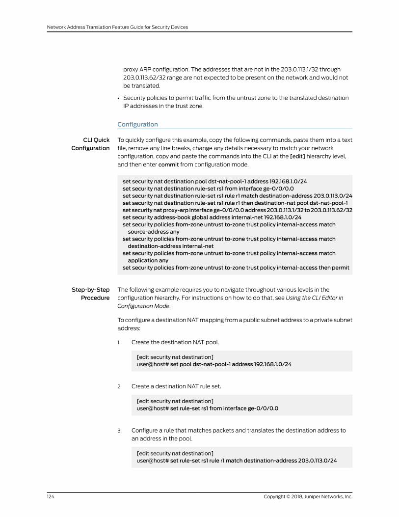
proxy ARP configuration. The addresses that are not in the 203.0.113.1/32 through
203.0.113.62/32 range are not expected to be present on the network and would not
be translated.
• Security policies to permit traffic from the untrust zone to the translated destination
IP addresses in the trust zone.
Configuration
CLI QuickConfiguration
To quickly configure this example, copy the following commands, paste them into a text
file, remove any line breaks, change any details necessary to match your network
configuration, copy and paste the commands into the CLI at the [edit] hierarchy level,
and then enter commit from configuration mode.
set security nat destination pool dst-nat-pool-1 address 192.168.1.0/24set security nat destination rule-set rs1 from interface ge-0/0/0.0set security nat destination rule-set rs1 rule r1 match destination-address 203.0.113.0/24set security nat destination rule-set rs1 rule r1 then destination-nat pool dst-nat-pool-1set securitynatproxy-arp interfacege-0/0/0.0address203.0.113.1/32 to203.0.113.62/32set security address-book global address internal-net 192.168.1.0/24set security policies from-zone untrust to-zone trust policy internal-accessmatchsource-address any
set security policies from-zone untrust to-zone trust policy internal-accessmatchdestination-address internal-net
set security policies from-zone untrust to-zone trust policy internal-accessmatchapplication any
set security policies from-zone untrust to-zone trust policy internal-access then permit
Step-by-StepProcedure
The following example requires you to navigate throughout various levels in the
configuration hierarchy. For instructions on how to do that, see Using the CLI Editor in
Configuration Mode.
To configure adestinationNATmapping fromapublic subnet address toaprivate subnet
address:
1. Create the destination NAT pool.
[edit security nat destination]user@host# set pool dst-nat-pool-1 address 192.168.1.0/24
2. Create a destination NAT rule set.
[edit security nat destination]user@host# set rule-set rs1 from interface ge-0/0/0.0
3. Configure a rule that matches packets and translates the destination address to
an address in the pool.
[edit security nat destination]user@host# set rule-set rs1 rule r1 match destination-address 203.0.113.0/24
Copyright © 2018, Juniper Networks, Inc.124
Network Address Translation Feature Guide for Security Devices

user@host# set rule-set rs1 rule r1 then destination-nat pool dst-nat-pool-1
4. Configure proxy ARP.
[edit security nat]user@host# set proxy-arp interface ge-0/0/0.0 address 203.0.113.1/32 to203.0.113.62/32
5. Configure an address in the global address book.
[edit security address-book global]user@host# set address internal-net 192.168.1.0/24
6. Configure a security policy that allows traffic from the untrust zone to the devices
in the trust zone.
[edit security policies from-zone untrust to-zone trust]user@host# set policy internal-accessmatch source-address anydestination-address internal-net application any
user@host# set policy internal-access then permit
Results From configuration mode, confirm your configuration by entering the show security nat
and show security policies commands. If the output does not display the intended
configuration, repeat the configuration instructions in this example to correct it.
[edit]user@host# show security natdestination {pool dst-nat-pool-1 {address 192.168.1.0/24;
}rule-set rs1 {from interface ge-0/0/0.0;rule r1 {match {destination-address 203.0.113.0/24;
}then {destination-nat pool dst-nat-pool-1;
}}
}}proxy-arp {interface ge-0/0/0.0 {address {203.0.113.1/32 to 203.0.113.62/32;
}
125Copyright © 2018, Juniper Networks, Inc.
Chapter 2: Types of NAT

}}
user@host# show security policiesfrom-zone untrust to-zone trust {policy internal-access {match {source-address any;destination-address internal-net;application any;
}then {permit;
}}
}
If you are done configuring the device, enter commit from configuration mode.
Verification
To confirm that the configuration is working properly, perform these tasks:
• Verifying Destination NAT Pool Usage on page 126
• Verifying Destination NAT Rule Usage on page 126
• Verifying NAT Application to Traffic on page 126
Verifying Destination NAT Pool Usage
Purpose Verify that there is traffic using IP addresses from the destination NAT pool.
Action From operational mode, enter the show security nat destination pool all command. View
the Translation hits field to check for traffic using IP addresses from the pool.
Verifying Destination NAT Rule Usage
Purpose Verify that there is traffic matching the destination NAT rule.
Action From operational mode, enter the show security nat destination rule all command. View
the Translation hits field to check for traffic that matches the rule.
Verifying NAT Application to Traffic
Purpose Verify that NAT is being applied to the specified traffic.
Action From operational mode, enter the show security flow session command.
Copyright © 2018, Juniper Networks, Inc.126
Network Address Translation Feature Guide for Security Devices
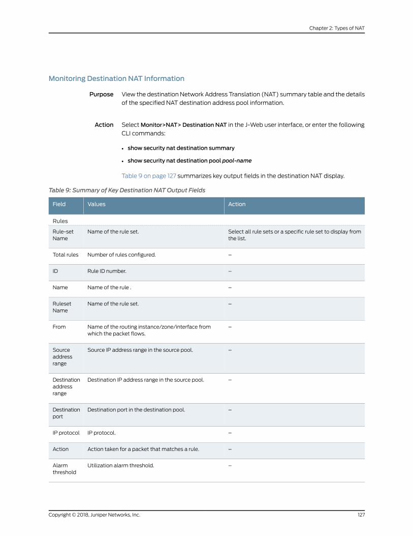
Monitoring Destination NAT Information
Purpose View the destination Network Address Translation (NAT) summary table and the details
of the specified NAT destination address pool information.
Action SelectMonitor>NAT> Destination NAT in the J-Web user interface, or enter the following
CLI commands:
• show security nat destination summary
• show security nat destination pool pool-name
Table 9 on page 127 summarizes key output fields in the destination NAT display.
Table 9: Summary of Key Destination NATOutput Fields
ActionValuesField
Rules
Select all rule sets or a specific rule set to display fromthe list.
Name of the rule set.Rule-setName
–Number of rules configured.Total rules
–Rule ID number.ID
–Name of the rule .Name
–Name of the rule set.RulesetName
–Name of the routing instance/zone/interface fromwhich the packet flows.
From
–Source IP address range in the source pool.Sourceaddressrange
–Destination IP address range in the source pool.Destinationaddressrange
–Destination port in the destination pool.Destinationport
–IP protocol.IP protocol
–Action taken for a packet that matches a rule.Action
–Utilization alarm threshold.Alarmthreshold
127Copyright © 2018, Juniper Networks, Inc.
Chapter 2: Types of NAT

Table 9: Summary of Key Destination NATOutput Fields (continued)
ActionValuesField
–Successful, failed, and current sessions.
• Succ–Number of successful session installationsafter the NAT rule is matched.
• Failed–Numberof unsuccessful session installationsafter the NAT rule is matched.
• Current–Number of sessions that reference thespecified rule.
Sessions(Succ/Failed/Current)
–Number of times a translation in the translation tableis used for a destination NAT rule.
Translationhits
Pools
Select all pools or a specific pool to display from thelist.
The names of the pools.Pool Name
–Total pools added.TotalPools
–ID of the pool.ID
–Name of the destination pool.Name
–IP address range in the destination pool.Addressrange
–Destination port number in the pool.Port
–Name of the routing instance.Routinginstance
–Total IP address, IP address set, or address book entry.Totaladdresses
–Number of times a translation in the translation tableis used for destination NAT.
Translationhits
Top 10 Translation Hits
–Displays the graph of top 10 translation hits.Graph
Static NAT
StaticNATmapsnetwork traffic fromastatic external IPaddress toan internal IPaddress
or network. It creates a static translation of real addresses to mapped addresses. Static
Copyright © 2018, Juniper Networks, Inc.128
Network Address Translation Feature Guide for Security Devices
NAT provides internet connectivity to networking devices through a private LANwith an
unregistered private IP address.
• Understanding Static NAT on page 129
• Understanding Static NAT Rules on page 129
• Static NAT Configuration Overview on page 130
• Example: Configuring Static NAT for Single Address Translation on page 130
• Example: Configuring Static NAT for Subnet Translation on page 136
• Example: Configuring Static NAT for Port Mapping on page 141
• Monitoring Static NAT Information on page 147
Understanding Static NAT
Static NAT defines a one-to-onemapping from one IP subnet to another IP subnet. The
mapping includesdestination IPaddress translation inonedirectionandsource IPaddress
translation in the reverse direction. From theNATdevice, the original destination address
is the virtual host IP address while the mapped-to address is the real host IP address.
Static NAT allows connections to be originated from either side of the network, but
translation is limited to one-to-one or between blocks of addresses of the same size. For
eachprivateaddress, apublic addressmustbeallocated.Noaddresspoolsarenecessary.
Static NAT also supports the following types of translation:
• Tomapmultiple IP addresses and specified ranges of ports to a same IP address and
different range of ports
• Tomap a specific IP address and port to a different IP address and port
The port address translation (PAT) is also supported by giving static mapping between
destination-port (range) andmapped-port (range).
NOTE: Theoriginaldestinationaddress, alongwithotheraddresses in sourceanddestinationNATpools,mustnotoverlapwithin thesamerouting instance.
In NAT rule lookup, static NAT rules take precedence over destination NAT rules and
reverse mapping of static NAT rules take precedence over source NAT rules.
Understanding Static NAT Rules
Static Network Address Translation (NAT) rules specify two layers of match conditions:
• Traffic direction—Allows you to specify from interface, from zone, or from
routing-instance.
• Packet information—Can be source addresses and ports, and destination addresses
and ports.
For all ALG traffic, except FTP, we recommend that you not use the static NAT rule
options source-address or source-port. Data session creation can fail if these options are
129Copyright © 2018, Juniper Networks, Inc.
Chapter 2: Types of NAT

used because the IP address and the source port value, which is a random value, might
not match the static NAT rule. For FTP ALG traffic, the source-address option can be
used because an IP address can be provided tomatch the source address of a static NAT
rule.
When both source and destination addresses are configured as match conditions for a
rule, traffic is matched to both the source address and destination address. Because
static NAT is bidirectional, traffic in the opposite direction reverse matches the rule, and
the destination address of the traffic is matched to the configured source address.
If multiple static NAT rules overlap in the match conditions, the most specific rule is
chosen. For example, if rules A and B specify the same source and destination IP
addresses, but ruleAspecifies traffic fromzone 1and ruleBspecifies traffic from interface
ge-0/0/0, rule B is used to perform static NAT. An interface match is considered to be
more specific than a zonematch, which is more specific than a routing instancematch.
Because static NAT rules do not support overlapping addresses and ports, they should
not be used to map one external IP address to multiple internal IP addresses for ALG
traffic. For example, if different siteswant toaccess twodifferent FTPservers, the internal
FTP servers should bemapped to two different external IP addresses.
For the static NAT rule action, specify the translated address and (optionally) the routing
instance.
In NAT lookup, static NAT rules take precedence over destination NAT rules and reverse
mapping of static NAT rules takes precedence over source NAT rules.
Static NAT Configuration Overview
Themain configuration tasks for static NAT are as follows:
1. Configure static NAT rules that align with your network and security requirements.
2. Configure NAT proxy ARP entries for IP addresses in the same subnet of the ingress
interface.
Example: Configuring Static NAT for Single Address Translation
This exampledescribeshowtoconfigureastaticNATmappingofa singleprivateaddress
to a public address.
• Requirements on page 131
• Overview on page 131
• Configuration on page 133
• Verification on page 135
Copyright © 2018, Juniper Networks, Inc.130
Network Address Translation Feature Guide for Security Devices

Requirements
Before you begin:
1. Configure network interfaces on the device. See Interfaces Feature Guide for Security
Devices.
2. Create security zonesandassign interfaces to them.SeeUnderstandingSecurity Zones.
Overview
This example uses the trust security zone for the private address space and the untrust
security zone for the public address space.
In Figure 12 on page 132, devices in the untrust zone access a server in the trust zone by
way of public address 203.0.113.200/32. For packets that enter the Juniper Networks
security device from the untrust zone with the destination IP address 203.0.113.200/32,
the destination IP address is translated to the private address 192.168.1.200/32. For a
new session originating from the server, the source IP address in the outgoing packet is
translated to the public address 203.0.113.200/32.
131Copyright © 2018, Juniper Networks, Inc.
Chapter 2: Types of NAT
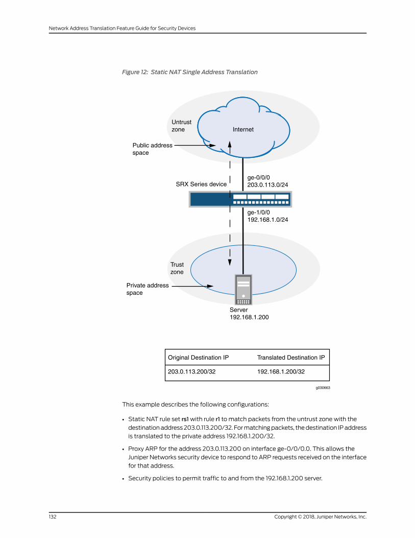
Figure 12: Static NAT Single Address Translation
Server192.168.1.200
Trustzone
ge-0/0/0203.0.113.0/24
ge-1/0/0192.168.1.0/24
SRX Series device
Untrustzone Internet
Public addressspace
Private addressspace
Original Destination IP Translated Destination IP
203.0.113.200/32 192.168.1.200/32
g030663
This example describes the following configurations:
• Static NAT rule set rs1with rule r1 to match packets from the untrust zone with the
destinationaddress203.0.113.200/32. Formatchingpackets, thedestination IPaddress
is translated to the private address 192.168.1.200/32.
• Proxy ARP for the address 203.0.113.200 on interface ge-0/0/0.0. This allows the
Juniper Networks security device to respond to ARP requests received on the interface
for that address.
• Security policies to permit traffic to and from the 192.168.1.200 server.
Copyright © 2018, Juniper Networks, Inc.132
Network Address Translation Feature Guide for Security Devices
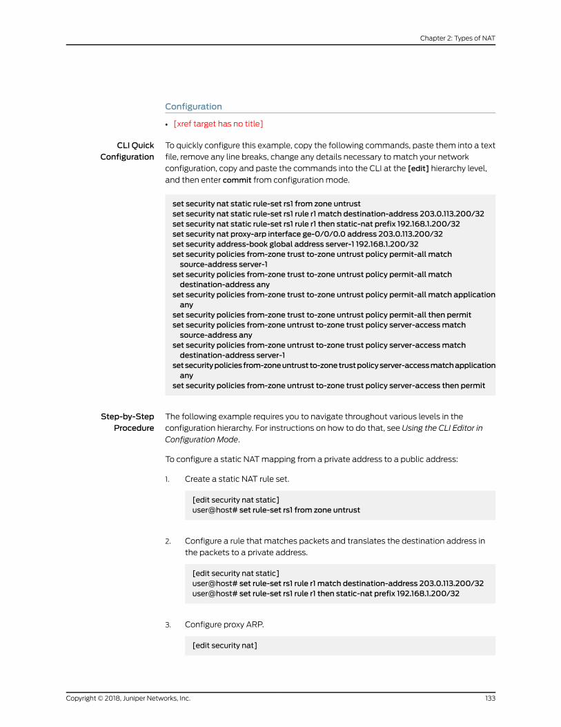
Configuration
• [xref target has no title]
CLI QuickConfiguration
To quickly configure this example, copy the following commands, paste them into a text
file, remove any line breaks, change any details necessary to match your network
configuration, copy and paste the commands into the CLI at the [edit] hierarchy level,
and then enter commit from configuration mode.
set security nat static rule-set rs1 from zone untrustset security nat static rule-set rs1 rule r1 match destination-address 203.0.113.200/32set security nat static rule-set rs1 rule r1 then static-nat prefix 192.168.1.200/32set security nat proxy-arp interface ge-0/0/0.0 address 203.0.113.200/32set security address-book global address server-1 192.168.1.200/32set security policies from-zone trust to-zone untrust policy permit-all matchsource-address server-1
set security policies from-zone trust to-zone untrust policy permit-all matchdestination-address any
set security policies from-zone trust to-zone untrust policy permit-all match applicationany
set security policies from-zone trust to-zone untrust policy permit-all then permitset security policies from-zone untrust to-zone trust policy server-accessmatchsource-address any
set security policies from-zone untrust to-zone trust policy server-accessmatchdestination-address server-1
setsecuritypoliciesfrom-zoneuntrustto-zonetrustpolicyserver-accessmatchapplicationany
set security policies from-zone untrust to-zone trust policy server-access then permit
Step-by-StepProcedure
The following example requires you to navigate throughout various levels in the
configuration hierarchy. For instructions on how to do that, see Using the CLI Editor in
Configuration Mode.
To configure a static NATmapping from a private address to a public address:
1. Create a static NAT rule set.
[edit security nat static]user@host# set rule-set rs1 from zone untrust
2. Configure a rule that matches packets and translates the destination address in
the packets to a private address.
[edit security nat static]user@host# set rule-set rs1 rule r1 match destination-address 203.0.113.200/32user@host# set rule-set rs1 rule r1 then static-nat prefix 192.168.1.200/32
3. Configure proxy ARP.
[edit security nat]
133Copyright © 2018, Juniper Networks, Inc.
Chapter 2: Types of NAT

user@host# set proxy-arp interface ge-0/0/0.0 address 203.0.113.200
4. Configure an address in the global address book.
[edit security address-book global]user@host# set address server-1 192.168.1.200/32
5. Configure a security policy that allows traffic from the untrust zone to the server in
the trust zone.
[edit security policies from-zone untrust to-zone trust]user@host#setpolicyserver-accessmatchsource-addressanydestination-addressserver-1 application any
user@host# set policy server-access then permit
6. Configure a security policy that allows all traffic from the server in the trust zone to
the untrust zone.
[edit security policies from-zone trust to-zone untrust]user@host#setpolicypermit-allmatchsource-addressserver-1destination-addressany application any
user@host# set policy permit-all then permit
Results From configuration mode, confirm your configuration by entering the show security nat
and show security policies commands. If the output does not display the intended
configuration, repeat the configuration instructions in this example to correct it.
[edit]user@host# show security natstatic {rule-set rs1 {from zone untrust;rule r1 {match {destination-address 203.0.113.200/32;
}then {static-nat prefix 192.168.1.200/32;
}}
}}proxy-arp {interface ge-0/0/0.0 {address {203.0.113.200/32;
}}
Copyright © 2018, Juniper Networks, Inc.134
Network Address Translation Feature Guide for Security Devices

}user@host# show security policiesfrom-zone trust to-zone untrust {policy permit-all {match {source-address server-1;destination-address any;application any;
}then {permit;
}}
}from-zone untrust to-zone trust {policy server-access {match {source-address any;destination-address server-1;application any;
}then {permit;
}}
}
If you are done configuring the device, enter commit from configuration mode.
Verification
To confirm that the configuration is working properly, perform these tasks:
• Verifying Static NAT Configuration on page 135
• Verifying NAT Application to Traffic on page 135
Verifying Static NAT Configuration
Purpose Verify that there is traffic matching the static NAT rule set.
Action From operational mode, enter the show security nat static rule command. View the
Translation hits field to check for traffic that matches the rule.
Verifying NAT Application to Traffic
Purpose Verify that NAT is being applied to the specified traffic.
Action From operational mode, enter the show security flow session command.
135Copyright © 2018, Juniper Networks, Inc.
Chapter 2: Types of NAT
Example: Configuring Static NAT for Subnet Translation
This example describes how to configure a static NATmapping of a private subnet
address to a public subnet address.
NOTE: Address blocks for static NATmappingmust be of the same size.
• Requirements on page 136
• Overview on page 136
• Configuration on page 138
• Verification on page 140
Requirements
Before you begin:
1. Configure network interfaces on the device. See Interfaces Feature Guide for Security
Devices.
2. Create security zonesandassign interfaces to them.SeeUnderstandingSecurity Zones.
Overview
This example uses the trust security zone for the private address space and the untrust
security zone for the public address space. In Figure 13 on page 137, devices in the untrust
zone access devices in the trust zone by way of public subnet address 203.0.113.0/24.
For packets that enter the Juniper Networks security device from the untrust zone with
a destination IP address in the 203.0.113.0/24 subnet, the destination IP address is
translated to aprivate address on the 192.168.1.0/24 subnet. For newsessions originating
from the 192.168.1.0/24 subnet, the source IP address in outgoing packets is translated
to an address on the public 203.0.113.0/24 subnet.
Copyright © 2018, Juniper Networks, Inc.136
Network Address Translation Feature Guide for Security Devices

Figure 13: Static NAT Subnet Translation
Trustzone
ge-0/0/0203.0.113.200/32
ge-1/0/0192.168.1.0/24
SRX Series device
Untrustzone Internet
Public addressspace
Private addressspace 192.168.1.0/24192.168.1.0/24
Original Destination IP Translated Destination IP
203.0.113.200/32 192.168.1.0/24
g030664
This example describes the following configurations:
• Static NAT rule set rs1with rule r1 to match packets received on interface ge-0/0/0.0
with a destination IP address in the 203.0.113.0/24 subnet. For matching packets, the
destination address is translated to an address on the 192.168.1.0/24 subnet.
• Proxy ARP for the address ranges 203.0.113.1/32 through 203.0.113.249/32 on interface
ge-0/0/0.0. This allows the Juniper Networks security device to respond to ARP
requests received on the interface for those addresses. The address 203.0.113.250/32
is assigned to the interface itself, so this address is not included in the proxy ARP
configuration.
• Security policies to permit traffic to and from the 192.168.1.0/24 subnet.
137Copyright © 2018, Juniper Networks, Inc.
Chapter 2: Types of NAT

Configuration
CLI QuickConfiguration
To quickly configure this example, copy the following commands, paste them into a text
file, remove any line breaks, change any details necessary to match your network
configuration, copy and paste the commands into the CLI at the [edit] hierarchy level,
and then enter commit from configuration mode.
set security nat static rule-set rs1 from interface ge-0/0/0.0set security nat static rule-set rs1 rule r1 match destination-address 203.0.113.0/24set security nat static rule-set rs1 rule r1 then static-nat prefix 192.168.1.0/24setsecuritynatproxy-arp interfacege-0/0/0.0address203.0.113.1/32to203.0.113.249/32set security address-book global address server-group 192.168.1.0/24set security policies from-zone trust to-zone untrust policy permit-all matchsource-address server-group
set security policies from-zone trust to-zone untrust policy permit-all matchdestination-address any
set security policies from-zone trust to-zone untrust policy permit-all match applicationany
set security policies from-zone trust to-zone untrust policy permit-all then permitset security policies from-zone untrust to-zone trust policy server-accessmatchsource-address any
set security policies from-zone untrust to-zone trust policy server-accessmatchdestination-address server-group
setsecuritypoliciesfrom-zoneuntrustto-zonetrustpolicyserver-accessmatchapplicationany
set security policies from-zone untrust to-zone trust policy server-access then permit
Step-by-StepProcedure
The following example requires you to navigate throughout various levels in the
configuration hierarchy. For instructions on how to do that, see Using the CLI Editor in
Configuration Mode.
To configure a static NATmapping from a private subnet address to a public subnet
address:
1. Create a static NAT rule set.
[edit security nat static]user@host# set rule-set rs1 from interface ge-0/0/0.0
2. Configure a rule that matches packets and translates the destination address in
the packets to an address in a private subnet.
[edit security nat static]user@host# set rule-set rs1 rule r1 match destination-address 203.0.113.0/24user@host# set rule-set rs1 rule r1 then static-nat prefix 192.168.1.0/24
3. Configure proxy ARP.
[edit security nat]
Copyright © 2018, Juniper Networks, Inc.138
Network Address Translation Feature Guide for Security Devices

user@host# set proxy-arp interface ge-0/0/0.0 address 203.0.113.1/32 to203.0.113.249/32
4. Configure an address in the global address book.
[edit security address-book global]user@host# set address server-group 192.168.1.0/24
5. Configure a security policy that allows traffic from the untrust zone to the subnet
in the trust zone.
[edit security policies from-zone untrust to-zone trust]user@host#setpolicyserver-accessmatchsource-addressanydestination-addressserver-group application any
user@host# set policy server-access then permit
6. Configure a security policy that allows all traffic from the subnet in the trust zone
to the untrust zone.
[edit security policies from-zone trust to-zone untrust]user@host# set policy permit-all match source-address server-groupdestination-address any application any
user@host# set policy permit-all then permit
Results From configuration mode, confirm your configuration by entering the show security nat
and show security policies commands. If the output does not display the intended
configuration, repeat the configuration instructions in this example to correct it.
[edit]user@host# show security natstatic {rule-set rs1 {from interface ge-0/0/0.0;rule r1 {match {destination-address 203.0.113.0/24;
}then {static-nat prefix 192.168.1.0/24;
}}
}}proxy-arp {interface ge-0/0/0.0 {address {203.0.113.1/32 to 203.0.113.249/32;
}
139Copyright © 2018, Juniper Networks, Inc.
Chapter 2: Types of NAT

}}
user@host# show security policiesfrom-zone trust to-zone untrust {policy permit-all {match {source-address server-group;destination-address any;application any;
}then {permit;
}}
}from-zone untrust to-zone trust {policy server-access {match {source-address any;destination-address server-group;application any;
}then {permit;
}}
}
If you are done configuring the device, enter commit from configuration mode.
Verification
To confirm that the configuration is working properly, perform these tasks:
• Verifying Static NAT Configuration on page 140
• Verifying NAT Application to Traffic on page 140
Verifying Static NAT Configuration
Purpose Verify that there is traffic matching the static NAT rule set.
Action From operational mode, enter the show security nat static rule command. View the
Translation hits field to check for traffic that matches the rule.
Verifying NAT Application to Traffic
Purpose Verify that NAT is being applied to the specified traffic.
Action From operational mode, enter the show security flow session command.
Copyright © 2018, Juniper Networks, Inc.140
Network Address Translation Feature Guide for Security Devices
Example: Configuring Static NAT for Port Mapping
This example describes how to configure static NATmappings of a public address to
private addresses on a specified range of ports.
This topic includes the following sections:
• Requirements on page 141
• Overview on page 141
• Configuration on page 143
• Verification on page 146
• Troubleshooting on page 146
Requirements
Before you begin:
• Configure network interfaces on the device. See Interfaces Feature Guide for Security
Devices.
• Create security zones andassign interfaces to them.SeeUnderstandingSecurity Zones.
Overview
This example uses the trust security zone for the private address space and the untrust
security zone for the public address space.
In Figure 14 on page 142, devices in the untrust zone access a server in the trust zone by
way of public addresses 203.0.113.1/32, 203.0.113.1/32, and 203.0.113.3/32. For packets
that enter the JuniperNetworks security device fromtheuntrust zonewith thedestination
IPaddresses203.0.113.1/32, 203.0.113.1/32, and203.0.113.3/32, thedestination IPaddress
is translated to the private addresses 10.1.1.1/32,10.1.1.2/32, and 10.1.1.2/32.
141Copyright © 2018, Juniper Networks, Inc.
Chapter 2: Types of NAT

Figure 14: Static NAT for Port Mapping
Trustzone
SRX Series device
Untrustzone
Private addressspace
Internet
Public addressspace
10.1.1.1/32
10.1.1.2/32
10.1.1.2/32
203.0.113.1/32
203.0.113.1/32
203.0.113.3/32
Bidirectionaltraffic flow
Original Source IP Translated Source IP
203.0.113.1/32 (port 100 to 200) 10.1.1.1/32 (port 300 to 400)203.0.113.1/32 (port 300 to 400) 10.1.1.2/32 (port 300 to 400)203.0.113.3/32 (port 300) 10.1.1.2/32 (port 200)
g034
403
Copyright © 2018, Juniper Networks, Inc.142
Network Address Translation Feature Guide for Security Devices
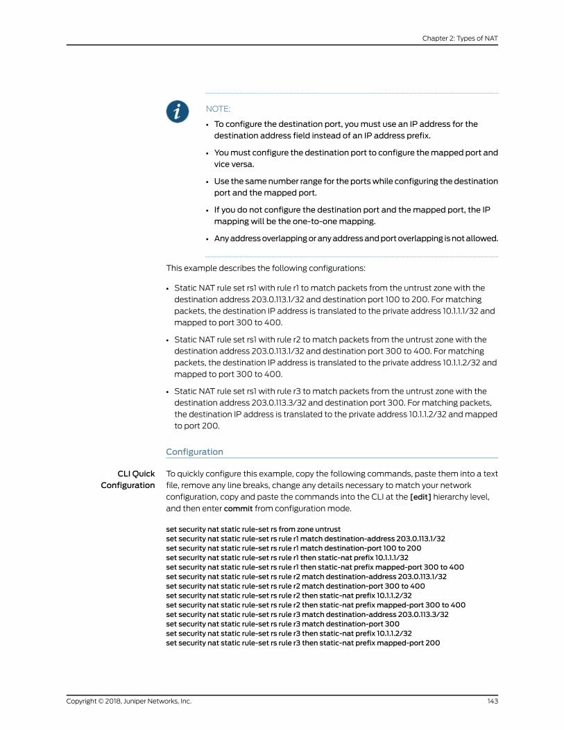
NOTE:
• To configure the destination port, youmust use an IP address for thedestination address field instead of an IP address prefix.
• Youmust configure the destination port to configure themapped port andvice versa.
• Use the samenumber range for the portswhile configuring the destinationport and themapped port.
• If you do not configure the destination port and themapped port, the IPmapping will be the one-to-onemapping.
• Anyaddressoverlappingoranyaddressandportoverlapping isnotallowed.
This example describes the following configurations:
• Static NAT rule set rs1 with rule r1 to match packets from the untrust zone with the
destination address 203.0.113.1/32 and destination port 100 to 200. For matching
packets, the destination IP address is translated to the private address 10.1.1.1/32 and
mapped to port 300 to 400.
• Static NAT rule set rs1 with rule r2 to match packets from the untrust zone with the
destination address 203.0.113.1/32 and destination port 300 to 400. For matching
packets, the destination IP address is translated to the private address 10.1.1.2/32 and
mapped to port 300 to 400.
• Static NAT rule set rs1 with rule r3 to match packets from the untrust zone with the
destination address 203.0.113.3/32 and destination port 300. For matching packets,
the destination IP address is translated to the private address 10.1.1.2/32 andmapped
to port 200.
Configuration
CLI QuickConfiguration
To quickly configure this example, copy the following commands, paste them into a text
file, remove any line breaks, change any details necessary to match your network
configuration, copy and paste the commands into the CLI at the [edit] hierarchy level,
and then enter commit from configuration mode.
set security nat static rule-set rs from zone untrustset security nat static rule-set rs rule r1 match destination-address 203.0.113.1/32set security nat static rule-set rs rule r1 match destination-port 100 to 200set security nat static rule-set rs rule r1 then static-nat prefix 10.1.1.1/32set security nat static rule-set rs rule r1 then static-nat prefix mapped-port 300 to 400set security nat static rule-set rs rule r2match destination-address 203.0.113.1/32set security nat static rule-set rs rule r2match destination-port 300 to 400set security nat static rule-set rs rule r2 then static-nat prefix 10.1.1.2/32set security nat static rule-set rs rule r2 then static-nat prefix mapped-port 300 to 400set security nat static rule-set rs rule r3match destination-address 203.0.113.3/32set security nat static rule-set rs rule r3match destination-port 300set security nat static rule-set rs rule r3 then static-nat prefix 10.1.1.2/32set security nat static rule-set rs rule r3 then static-nat prefix mapped-port 200
143Copyright © 2018, Juniper Networks, Inc.
Chapter 2: Types of NAT

Step-by-StepProcedure
The following example requires you to navigate throughout various levels in the
configuration hierarchy. For instructions on how to do that, see Using the CLI Editor in
Configuration Mode.
To configure a static NATmapping from a private subnet address to a public subnet
address:
1. Create a static NAT rule set.
[edit security nat static]user@host# set rule-set rs from zone untrust
2. Configure a rule that matches packets and translates the destination address in
the packets to a private address.
[edit security nat static]user@host# set rule-set rs rule r1 match destination-address 203.0.113.1/32user@host# set rule-set rs rule r1 match destination-port 100 to 200user@host# set rule-set rs rule r1 then static-nat prefix 10.1.1.1/32user@host# set rule-set rs rule r1 then static-nat prefix mapped-port 300 to 400
3. Configure a rule that matches packets and translates the destination address in
the packets to a private address.
[edit security nat static]user@host# set rule-set rs rule r2match destination-address 203.0.113.1/32user@host# set rule-set rs rule r2match destination-port 300 to 400user@host# set rule-set rs rule r2 then static-nat prefix 10.1.1.2/32user@host# set rule-set rs rule r2 then static-nat prefix mapped-port 300 to 400
4. Configure a rule that matches packets and translates the destination address in
the packets to a private address.
[edit security nat static]user@host# set rule-set rs rule r3match destination-address 203.0.113.3/32user@host# set rule-set rs rule r3match destination-port 300user@host# set rule-set rs rule r3 then static-nat prefix 10.1.1.2/32user@host# set rule-set rs rule r3 then static-nat prefix mapped-port 200
Results
From configuration mode, confirm your configuration by entering the show security nat
command. If the output does not display the intended configuration, repeat the
configuration instructions in this example to correct it.
[edit]
user@host# show security nat
Copyright © 2018, Juniper Networks, Inc.144
Network Address Translation Feature Guide for Security Devices
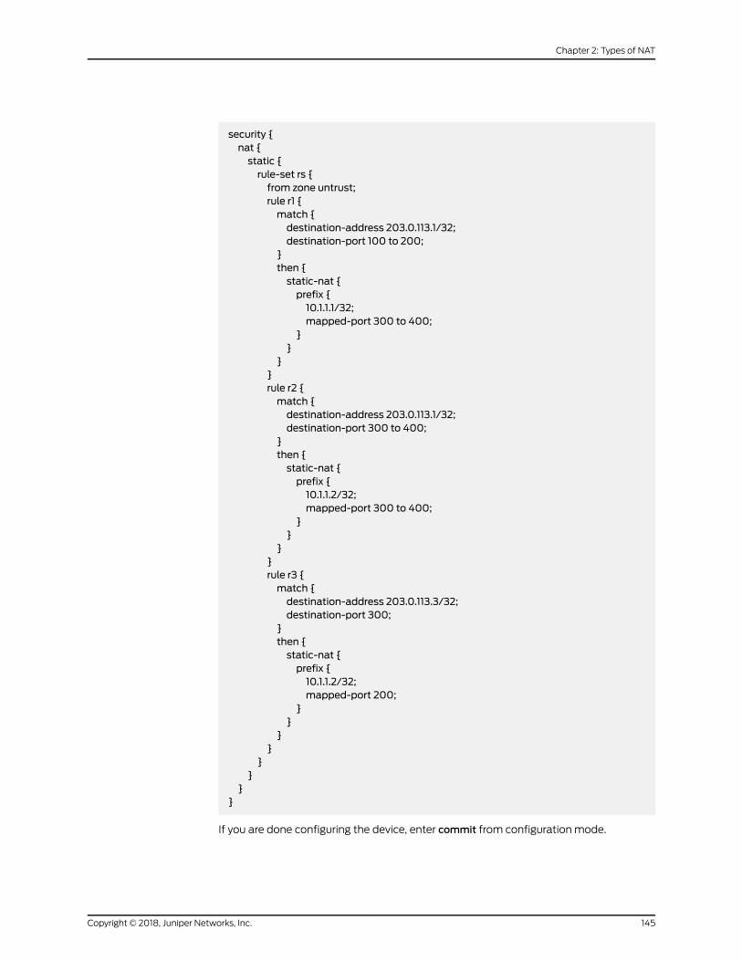
security {nat {static {rule-set rs {from zone untrust;rule r1 {match {destination-address 203.0.113.1/32;destination-port 100 to 200;
}then {static-nat {prefix {10.1.1.1/32;mapped-port 300 to 400;
}}
}}rule r2 {match {destination-address 203.0.113.1/32;destination-port 300 to 400;
}then {static-nat {prefix {10.1.1.2/32;mapped-port 300 to 400;
}}
}}rule r3 {match {destination-address 203.0.113.3/32;destination-port 300;
}then {static-nat {prefix {10.1.1.2/32;mapped-port 200;
}}
}}
}}
}}
If you are done configuring the device, enter commit from configuration mode.
145Copyright © 2018, Juniper Networks, Inc.
Chapter 2: Types of NAT

Verification
Verifying Static NAT Configuration
Purpose Verify that there is traffic matching the static NAT rule set.
Action From operational mode, enter the show security nat static rule command. View the
Translation hits field to check for traffic that matches the rule.
user@host> show security nat static rule all
Total static-nat rules: 3
Static NAT rule: r2 Rule-set: rs Rule-Id : 3 Rule position : 2 From zone : untrust Destination addresses : 203.0.113.1 Destination ports : 300 - 400 Host addresses : 10.1.1.2 Host ports : 300 - 400 Netmask : 32 Host routing-instance : N/A Translation hits : 0
Static NAT rule: r3 Rule-set: rs Rule-Id : 4 Rule position : 3 From zone : untrust Destination addresses : 203.0.113.3 Destination ports : 300 - 300 Host addresses : 10.1.1.2 Host ports : 200 - 200 Netmask : 32 Host routing-instance : N/A Translation hits : 0
Static NAT rule: r1 Rule-set: rs Rule-Id : 9 Rule position : 1 From zone : untrust Destination addresses : 203.0.113.1 Destination ports : 100 - 200 Host addresses : 10.1.1.1 Host ports : 300 - 400 Netmask : 32 Host routing-instance : N/A Translation hits : 0
Troubleshooting
• Troubleshooting Static NAT Port Configuration on page 146
Troubleshooting Static NAT Port Configuration
Problem Static NAT port mapping configuration failures occur during a commit.
Copyright © 2018, Juniper Networks, Inc.146
Network Address Translation Feature Guide for Security Devices
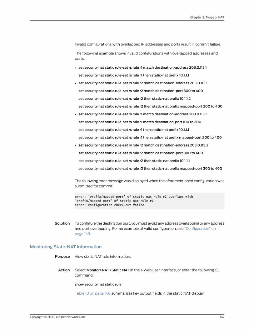
Invalid configurations with overlapped IP addresses and ports result in commit failure.
The following example shows invalid configurations with overlapped addresses and
ports:
• set security nat static rule-set rs rule r1 match destination-address 203.0.113.1
set security nat static rule-set rs rule r1 then static-nat prefix 10.1.1.1
• set security nat static rule-set rs rule r2match destination-address 203.0.113.1
set security nat static rule-set rs rule r2match destination-port 300 to 400
set security nat static rule-set rs rule r2 then static-nat prefix 10.1.1.2
set security nat static rule-set rs rule r2 then static-nat prefix mapped-port 300 to 400
• set security nat static rule-set rs rule r1 match destination-address 203.0.113.1
set security nat static rule-set rs rule r1 match destination-port 100 to 200
set security nat static rule-set rs rule r1 then static-nat prefix 10.1.1.1
set security nat static rule-set rs rule r1 then static-nat prefix mapped-port 300 to 400
• set security nat static rule-set rs rule r2match destination-address 203.0.113.2
set security nat static rule-set rs rule r2match destination-port 300 to 400
set security nat static rule-set rs rule r2 then static-nat prefix 10.1.1.1
set security nat static rule-set rs rule r2 then static-nat prefix mapped-port 390 to 490
The following errormessagewas displayedwhen the aforementioned configurationwas
submitted for commit:
error: 'prefix/mapped-port' of static nat rule r2 overlaps with 'prefix/mapped-port' of static nat rule r1error: configuration check-out failed
Solution Toconfigure thedestinationport, youmust avoid anyaddress overlappingor anyaddress
and port overlapping. For an example of valid configuration, see “Configuration” on
page 143.
Monitoring Static NAT Information
Purpose View static NAT rule information.
Action SelectMonitor>NAT>Static NAT in the J-Web user interface, or enter the following CLI
command:
show security nat static rule
Table 10 on page 148 summarizes key output fields in the static NAT display.
147Copyright © 2018, Juniper Networks, Inc.
Chapter 2: Types of NAT

Table 10: Summary of Key Static NATOutput Fields
ActionValuesField
Select all rule sets or a specific rule set todisplay from the list.
Name of the rule set.Rule-set Name
–Number of rules configured.Total rules
–Rule ID number.ID
–Position of the rule that indicates the order in which itapplies to traffic.
Position
–Name of the rule.Name
–Name of the rule set.Ruleset Name
–Name of the routing instance/interface/zone fromwhichthe packet comes
From
–Source IP addresses.Sourceaddresses
–Source port numbers.Source ports
–Destination IP address and subnet mask.Destinationaddresses
–Destination port numbers .Destinationports
–Name of the host addresses.Host addresses
Host port numbers.Host ports
–Subnet IP address.Netmask
–Nameof the routing instance fromwhich thepacketcomes.Host routinginstance
–Utilization alarm threshold.Alarmthreshold
–Successful, failed, and current sessions.
• Succ–Number of successful session installations afterthe NAT rule is matched.
• Failed–Number of unsuccessful session installationsafter the NAT rule is matched.
• Current–Numberof sessions that reference thespecifiedrule.
Sessions(Succ/Failed/Current)
Copyright © 2018, Juniper Networks, Inc.148
Network Address Translation Feature Guide for Security Devices
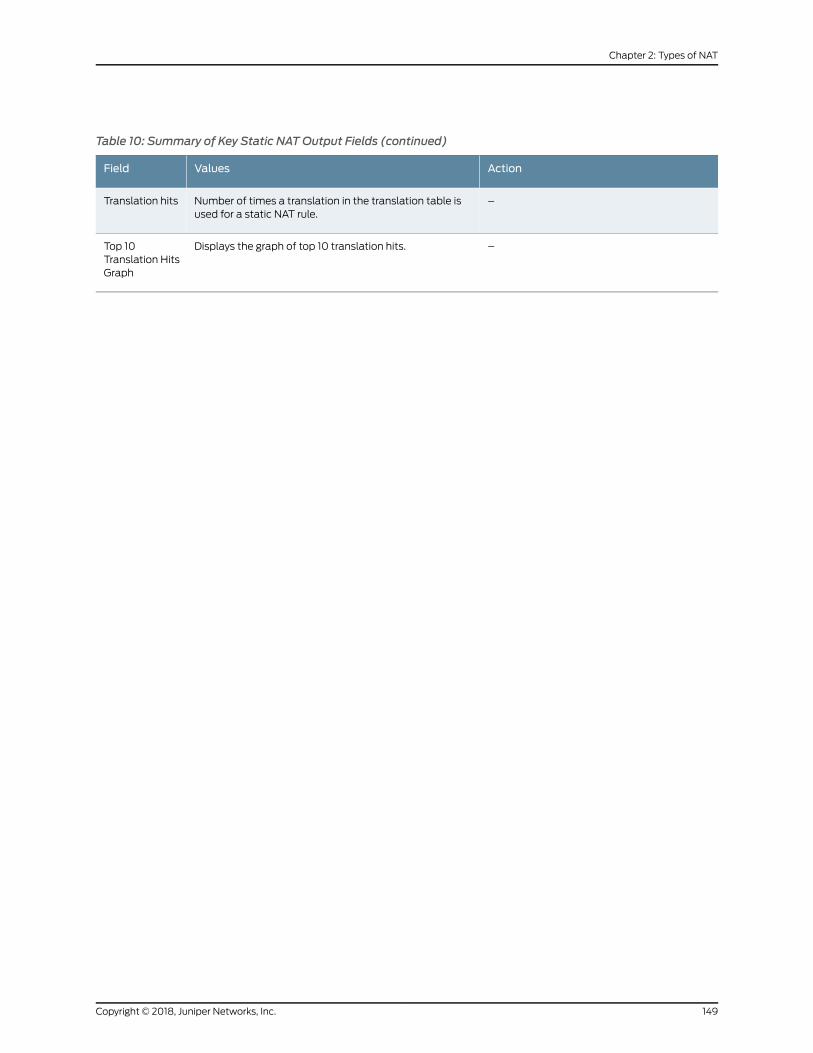
Table 10: Summary of Key Static NATOutput Fields (continued)
ActionValuesField
–Number of times a translation in the translation table isused for a static NAT rule.
Translation hits
–Displays the graph of top 10 translation hits.Top 10Translation HitsGraph
149Copyright © 2018, Juniper Networks, Inc.
Chapter 2: Types of NAT

Copyright © 2018, Juniper Networks, Inc.150
Network Address Translation Feature Guide for Security Devices

CHAPTER 3
NAT Configuration Options
• Persistent NAT and NAT64 on page 151
• NAT for Multicast Flows on page 180
• IPv6 NAT on page 191
• IPv6 Dual-Stack Lite on page 209
Persistent NAT and NAT64
Network Address Translators (NATs) are well known to cause very significant problems
with applications that carry IP addresses in the payload. Applications that suffer from
this problem include Voice Over IP and Multimedia Over IP. Persistent NAT improves
NATs behavior and defines a set of NAT requirement behavior which is useful for VOIP
applications working. NAT64 is a translating mechanism used to translate IPv6 packets
to IPv4 packets and vice versa by translating the packet headers according to IP/ICMP
Translation Algorithm.
• Understanding Persistent NAT and NAT64 on page 151
• Understanding Session Traversal Utilities for NAT (STUN) Protocol on page 153
• Understanding NAT64 IPv6 Prefix to IPv4 Address-Persistent Translation on page 154
• Persistent NAT and NAT64 Configuration Overview on page 155
• Example: Configuring Address Persistent NAT64 Pools on page 157
• Example: Supporting Network Configuration By Configuring Persistent NAT with
Interface NAT on page 159
• Example: Configuring Address-Dependent Filtering for IPv6 Clients on page 165
• Example: Configuring Endpoint-Independent Filtering for IPv6 Clients on page 169
• Example: Setting Maximum Persistent NAT Bindings on page 172
• Persistent NAT Hairpinning Overview on page 174
• Example: Configuring Persistent NAT Hairpinning with Source NAT Pool with Address
Shifting on page 174
Understanding Persistent NAT and NAT64
Persistent NAT allows applications to use the Session Traversal Utilities for NAT (STUN)
protocol when passing through NAT firewalls. Persistent NAT ensures that all requests
151Copyright © 2018, Juniper Networks, Inc.

from the same internal transport address (internal IP address and port) are mapped to
the same reflexive transport address (the public IP address and port created by the NAT
device closest to the STUN server).
NAT64 is a mechanism for translating IPv6 packets to IPv4 packets and vice versa that
allows IPv6 clients to contact IPv4 servers using unicast UDP, TCP, or ICMP. It is an
enhancement of Network Address Translation-Protocol Translation (NAT-PT).
NAT64 supports the following:
• Endpoint-independent mappings
• Endpoint-independent filtering and address-dependent filtering
NOTE: Themapping and filtering behaviors of NAT64 and persistent NATare identical.
The following types of persistent NAT can be configured on the Juniper Networks device:
• Any remote host—All requests froma specific internal IP address andport aremapped
to the same reflexive transport address. Any external host can send a packet to the
internal host by sending the packet to the reflexive transport address.
• Target host—All requests from a specific internal IP address and port are mapped to
the same reflexive transport address. An external host can send a packet to an internal
host by sending the packet to the reflexive transport address. The internal host must
have previously sent a packet to the external host’s IP address.
• Target host port—All requests from a specific internal IP address and port aremapped
to the same reflexive transport address. An external host can send a packet to an
internal host by sending thepacket to the reflexive transport address. The internal host
must have previously sent a packet to the external host’s IP address and port.
NOTE: The target-host-port configuration is not supported for NAT64when configured with IPv6 address.
You configure any of the persistent NAT types with source NAT rules. The source NAT
rule action can use a source NAT pool (with or without port translation) or an egress
interface. Persistent NAT is not applicable for destination NAT, because persistent NAT
bindings are based on outgoing sessions from internal to external.
Copyright © 2018, Juniper Networks, Inc.152
Network Address Translation Feature Guide for Security Devices
NOTE: Port overloading is used in Junos OS only for normal interface NATtraffic. Persistent NAT does not support port overloading, and youmustexplicitly disable port overloading with one of the following options at the[edit security nat source] hierarchy level:
• port-overloading off
• port-overloading-factor 1
To configure security policies to permit or deny persistent NAT traffic, you can use two
new predefined services—junos-stun and junos-persistent-nat.
NOTE: Persistent NAT is different from the persistent address feature (see“Understanding Persistent Addresses for Source NAT Pools” on page 78).The persistent address feature applies to addressmappings for source NATpools configuredon thedevice.ThepersistentNATfeatureapplies toaddressmappings on an external NAT device, and is configured for a specific sourceNAT pool or egress interface. Also, persistent NAT is intended for use withSTUN client/server applications.
Understanding Session Traversal Utilities for NAT (STUN) Protocol
Many video and voice applications do not work properly in a NAT environment. For
example, Session Initiation Protocol (SIP), used with VoIP, encodes IP addresses and
port numbers within application data. If a NAT firewall exists between the requestor and
receiver, the translation of the IP address and port number in the data invalidates the
information.
Also, a NAT firewall does not maintain a pinhole for incoming SIPmessages. This forces
the SIP application to either constantly refresh the pinhole with SIP messages or use an
ALG to track registration, a function that may or may not be supported by the gateway
device.
TheSessionTraversal Utilities forNAT (STUN)protocol, first defined inRFC3489, Simple
Traversal of User Datagram Protocol (UDP) Through Network Address Translators (NATs)
and then later in RFC 5389, Session Traversal Utilities for NAT, is a simple client/server
protocol. A STUN client sends requests to a STUN server, which returns responses to the
client. A STUN client is usually part of an application that requires a public IP address
and/or port. STUN clients can reside in an end system such as a PC or in a network server
whereas STUN servers are usually attached to the public Internet.
NOTE: Both the STUN client and STUN server must be provided by theapplication. Juniper Networks does not provide a STUN client or server.
The STUN protocol allows a client to:
153Copyright © 2018, Juniper Networks, Inc.
Chapter 3: NAT Configuration Options

• Discover whether the application is behind a NAT firewall.
• Determine the type of NAT binding being used.
• Learn the reflexive transport address,which is the IPaddressandport bindingallocated
by NAT device closest to the STUN server. (There may bemultiple levels of NAT
between the STUN client and the STUN server.)
The client application can use the IP address binding information within protocols such
as SIP and H.323.
Understanding NAT64 IPv6 Prefix to IPv4 Address-Persistent Translation
The NAT64mechanism enables IPv6 clients to contact IPv4 servers by translating IPv6
addresses to IPv4 addresses (and vice versa). However, some IPv4 applications and
services cannot work correctly over IPv6-only networks with standard NAT64 in a
dual-translation scenario, such as 464XLAT. In those scenarios, address-persistent
translation is required.
Figure 15 on page 154 illustrates the 464XLAT architecture, whereby IPv4 packets are
translated to IPv6 packets on the customer-side translator (CLAT), then go across the
IPv6-onlynetwork, andare translatedback to IPv4packetson theprovider-side translator
(PLAT) to access global IPv4-only content in the core network. This architecture uses a
combination of stateless translation on the CLAT and stateful translation on the PLAT.
Figure 15: 464XLAT Architecture
When an SRX Series device functions as a PLAT, it is responsible for keeping the sticky
mapping relationship between one specific IPv6 prefix and one translated IPv4 address.
TheSRXSeriesdevice treats the IPv6prefix asasingleuser. Thismapping isaccomplished
by configuring the specific IPv6 prefix length in an IPv4 source NAT pool using the
address-persistent feature.
Copyright © 2018, Juniper Networks, Inc.154
Network Address Translation Feature Guide for Security Devices
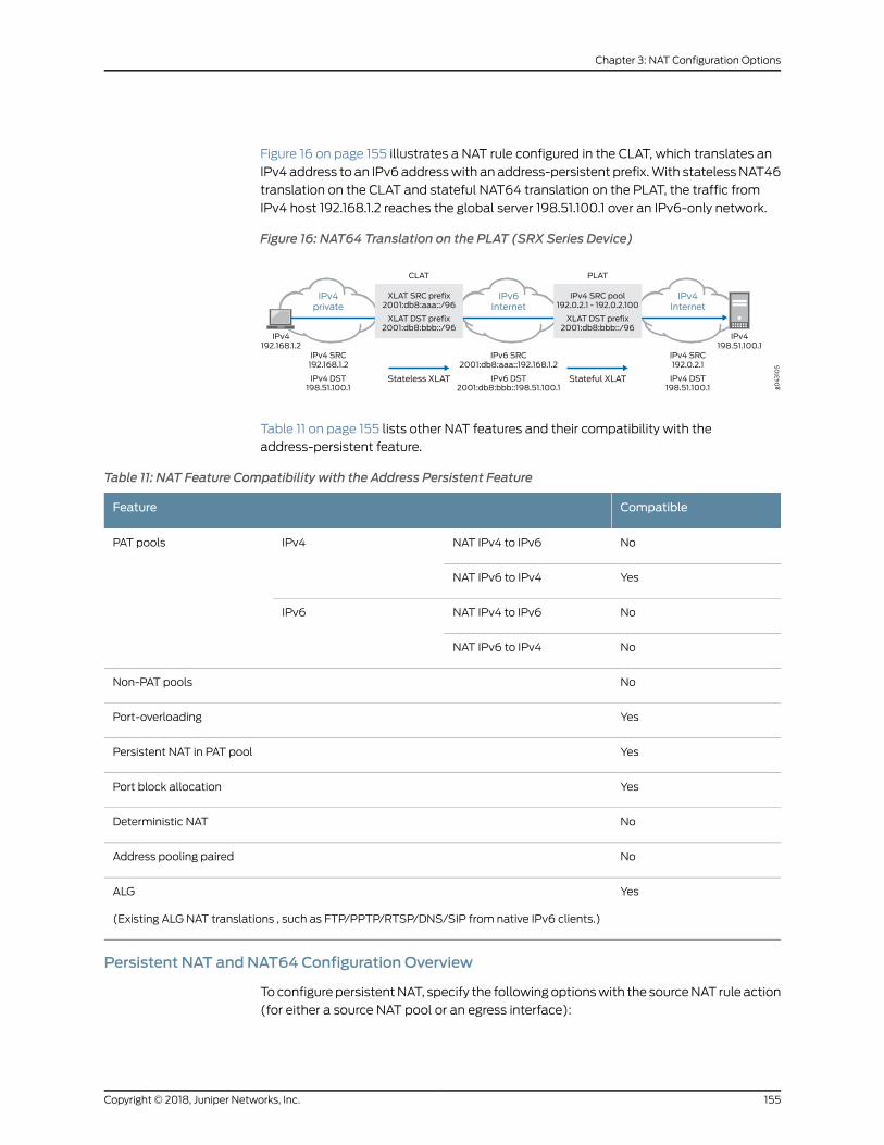
Figure 16 on page 155 illustrates a NAT rule configured in the CLAT, which translates an
IPv4 address to an IPv6 addresswith an address-persistent prefix.With statelessNAT46
translation on the CLAT and stateful NAT64 translation on the PLAT, the traffic from
IPv4 host 192.168.1.2 reaches the global server 198.51.100.1 over an IPv6-only network.
Figure 16: NAT64 Translation on the PLAT (SRX Series Device)
Table 11 on page 155 lists other NAT features and their compatibility with the
address-persistent feature.
Table 11: NAT Feature Compatibility with the Address Persistent Feature
CompatibleFeature
NoNAT IPv4 to IPv6IPv4PAT pools
YesNAT IPv6 to IPv4
NoNAT IPv4 to IPv6IPv6
NoNAT IPv6 to IPv4
NoNon-PAT pools
YesPort-overloading
YesPersistent NAT in PAT pool
YesPort block allocation
NoDeterministic NAT
NoAddress pooling paired
YesALG
(Existing ALG NAT translations , such as FTP/PPTP/RTSP/DNS/SIP from native IPv6 clients.)
Persistent NAT and NAT64 Configuration Overview
ToconfigurepersistentNAT, specify the followingoptionswith the sourceNAT rule action
(for either a source NAT pool or an egress interface):
155Copyright © 2018, Juniper Networks, Inc.
Chapter 3: NAT Configuration Options
• The type of persistent NAT—One of the following: any remote host, target host, or
target host port.
• (Optional) Address mapping—This option allows requests from a specific internal IP
address to bemapped to the same reflexive IP address; internal and reflexive ports
can be any ports. An external host using any port can send apacket to the internal host
by sending the packet to the reflexive IP address (with a configured incoming policy
that allows external to internal traffic). If this option is not configured, the persistent
NAT binding is for specific internal and reflexive transport addresses.
You can only specify the address-mapping option when the persistent NAT type is any
remote host and the source NAT rule action is one of the following actions:
• Source NAT pool with IP address shifting
• Source NAT pool with no port translation and no overflow pool
• (Optional) Inactivity timeout—Time, in seconds, that thepersistentNATbinding remains
in the device’s memory when all the sessions of the binding entry have expired. When
the configured timeout is reached, the binding is removed frommemory. The default
value is 300 seconds. Configure a value from 60 through 7200 seconds.
When all sessions of a persistent NAT binding have expired, the binding remains in a
query state in the SRX Series device’s memory for the specified inactivity timeout
period. The query binding is automatically removed frommemory when the inactivity
timeout period expires (the default is 300 seconds). You can explicitly remove all or
specific persistent NAT query bindings with the clear security nat source
persistent-nat-table command.
• (Optional) Maximum session number—Maximum number of sessions with which a
persistentNATbinding canbeassociated. Thedefault is 30 sessions. Configure a value
from 8 through 100.
For interfaceNAT, youneed toexplicitly disableport overloadingwithoneof the following
options at the [edit security nat source] hierarchy level:
• port-overloading off
• port-overloading-factor 1
Finally, there are two predefined services that you can use in security policies to permit
or deny STUN and persistent NAT traffic:
• junos-stun—STUN protocol traffic.
• junos-persistent-nat—Persistent NAT traffic.
For the any remote host persistent NAT type, the direction of the security policy is from
external to internal. For target host or target host port persistent NAT types, the direction
of the security policy is from internal to external.
Copyright © 2018, Juniper Networks, Inc.156
Network Address Translation Feature Guide for Security Devices

Example: Configuring Address Persistent NAT64 Pools
This example shows how to configure address persistent NAT64 pools to ensure a sticky
mapping relationship between one specific IPv6 prefix, which is calculated by the
configured IPv6 prefix length, and one translated IPv4 address.
• Requirements on page 157
• Overview on page 157
• Configuration on page 157
• Verification on page 159
Requirements
Before you begin, be sure the existing NAT rules and pool configuration do not conflict
with the new one.
Overview
In this example, you configure an IPv6 prefix length of /64 in an IPv4 source NAT pool
for NAT IPv6 to IPv4 translations. Traffic matching the NAT rule and NAT pool perform
address persistent translation between the IPv6 prefix and the IPv4 translated address.
This configurationcanbeusedon theprovider-side translator (PLAT) inadual-translation
scenario, 464XLAT, to enable IPv4 services to work over IPv6-only networks.
Configuration
CLI QuickConfiguration
To quickly configure this example, copy the following commands, paste them into a text
file, remove any line breaks, change any details necessary to match your network
configuration, copy and paste the commands into the CLI at the [edit] hierarchy level,
and then enter commit from configuration mode.
set security nat source pool NAT64 address 198.51.100.240/32 to 198.51.100.254/32set security nat source pool NAT64 address-persistent subscriber ipv6-prefix-length 64set security nat source rule-set RS1 from zone trustset security nat source rule-set RS1 to zone untrustset security nat source rule-set RS1 rule R1match source-address 2001:db8::/32set security nat source rule-set RS1 rule R1match destination-address 198.51.100.198/32set security nat source rule-set RS1 rule R1 then source-nat pool NAT64
Step-by-StepProcedure
The following example requires you to navigate throughout various levels in the
configuration hierarchy. For instructions on how to do that, see Using the CLI Editor in
Configuration Mode.
1. Create a source NAT pool.
[edit security nat source]user@host# set pool NAT64 address 198.51.100.240/32 to 198.51.100.254/32
2. Specify the IPv6 prefix length for the source NAT pool.
157Copyright © 2018, Juniper Networks, Inc.
Chapter 3: NAT Configuration Options

[edit security nat source]user@host# set pool NAT64 address-persistent subscriber ipv6-prefix-length 64
3. Create a rule set.
[edit security nat source]user@host# set rule-set RS1 from zone trustuser@host# set rule-set RS1 to zone untrust
4. Match the rule.
[edit security nat source]user@host# set rule-set RS1 rule R1match source-address 2001:db8::/32user@host# set rule-set RS1 rule R1match destination-address 198.51.100.198/32
5. Provide the action to be performed when the rule matches.
[edit security nat source]user@host# set security nat source rule-setRS1 ruleR1 then source-natpoolNAT64
Results From configuration mode, confirm your configuration by entering the show security nat
command. If the output does not display the intended configuration, repeat the
configuration instructions in this example to correct it.
[edit]user@host# show security natsource {pool NAT64 {address {198.51.100.240/32 to 198.51.100.254/32;
}address-persistent subscriber ipv6-prefix-length 64;
}rule-set RS1 {from zone trust;to zone untrust;rule R1 {match {source-address 2001:db8::/32;destination-address 198.51.100.198/32;
}then {source-nat {pool {NAT64;
}}
}}
Copyright © 2018, Juniper Networks, Inc.158
Network Address Translation Feature Guide for Security Devices
}}
If you are done configuring the device, enter commit from configuration mode.
Verification
Verifying NAT Application to Traffic
Purpose Verify that the same IPv6 prefix is translated to the persistent IPv4 address.
Action From operational mode, enter the show security flow session command.
Example: SupportingNetworkConfigurationByConfiguringPersistentNATwith InterfaceNAT
You can configure any of the persistent NAT types with source NAT rules. This example
illustrates how to apply persistent NAT with an interface IP address and how to use an
interface IP address as a NAT IP address to perform persistent NAT for a specific internal
host. It also shows how tomaintain persistent address port mapping behavior and
persistentNAT filter behavior for thehost. Youmust disable port overloading for interface
NAT.
• Requirements on page 159
• Overview on page 159
• Configuration on page 161
• Verification on page 164
Requirements
This example uses the following hardware and software components:
• 1 SRX Series device
• 4 PCs
Before you begin:
• Understand the concepts of persistent NAT. See “Persistent NAT and NAT64
Configuration Overview” on page 155.
Overview
In a Carrier Grade NAT (CGN) network deployment, you can configure the interface IP
address as a NAT address to perform persistent network address translation. In this way,
the internal host can create one source NATmapping relationship by the outgoing traffic
initiated from internal to external. Then theexternal host sends traffic back to this internal
host by sending the traffic to this interfaceNATaddress through the sharedNATmapping
relationship.
159Copyright © 2018, Juniper Networks, Inc.
Chapter 3: NAT Configuration Options

In this example, you first configure the interface NAT rule set int1 to match traffic from
interface ge-0/0/1 to interface ge-0/0/2, and then you configure the NAT rule in1 to
match the specific source and destination addresses to perform persistent NAT. You
configure the any remote host persistent NAT type when interface NAT is performed.
For packetswith source address 192.0.2.0/24 (internal phones) and destination address
198.51.100.0/24 (including STUN server, SIP proxy server, and external phones), you
configure interface NATwith the any remote host persistent NAT type. Then you disable
port overloading for interface NAT.
Next, you configure a security policy to allow persistent NAT traffic from the external
network (external zone) to the internal network (internal zone) for any of the remote
host persistent NAT types.
Topology
Figure 17 on page 160 shows an interface persistent NAT topology.
Figure 17: Interface Persistent NAT Topology
Table 12 on page 160 shows the parameters configured in this example.
Table 12: Interfaces, Zones, Servers, and IP Address Information
DescriptionParameter
External networkExternal Zone
Internal networkInternal Zone
Copyright © 2018, Juniper Networks, Inc.160
Network Address Translation Feature Guide for Security Devices
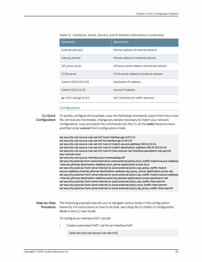
Table 12: Interfaces, Zones, Servers, and IP Address Information (continued)
DescriptionParameter
Phone2 address of external networkExternal_phones2
Phone1 address of internal networkInternal_phone1
SIP proxy server address of external networkSIP_proxy server
STUN server address of external networkSTUN server
Destination IP addressSubnet 198.51.100.1/32
Source IP addressSubnet 192.0.2.2/32
NAT interfaces for traffic directionge-0/0/1 and ge-0/0/2
Configuration
CLI QuickConfiguration
To quickly configure this example, copy the following commands, paste them into a text
file, remove any line breaks, change any details necessary to match your network
configuration, copy and paste the commands into the CLI at the [edit] hierarchy level,
and then enter commit from configuration mode.
set security nat source rule-set int1 from interface ge-0/0/1.0set security nat source rule-set int1 to interface ge-0/0/2.0set security nat source rule-set int1 rule in1 match source-address 192.0.2.0/24set security nat source rule-set int1 rule in1 match destination-address 198.51.100.0/24set security nat source rule-set int1 rule in1 then source-nat interface persistent-nat permitany-remote-hostset security nat source interface port-overloading offsetsecuritypolicies from-zone internal to-zoneexternalpolicystun_trafficmatchsource-addressinternal_phones destination-address stun_server application junos-stunset security policies from-zone internal to-zone external policy sip_proxy_traffic matchsource-address internal_phones destination-address sip_proxy_server application junos-sipset security policies from-zone internal to-zone external policy sip_traffic match source-addressinternal_phones destination-address external_phones application junos-persistent-natset security policies from-zone internal to-zone external policy sip_traffic then permitset security policies from-zone internal to-zone external policy stun_traffic then permitset security policies from-zone internal to-zone external policy sip_proxy_traffic then permit
Step-by-StepProcedure
The following example requires you to navigate various levels in the configuration
hierarchy. For instructions on how to do that, see Using the CLI Editor in Configuration
Mode in the CLI User Guide.
To configure an interface NAT rule set:
1. Create a persistent NAT rule for an interface NAT.
[edit security nat source rule-set int1]
161Copyright © 2018, Juniper Networks, Inc.
Chapter 3: NAT Configuration Options

user@host# set from interface ge-0/0/1.0user@host# set to interface ge-0/0/2.0user@host# set rule in1 match source-address 192.0.2.0/24user@host# set rule in1 match destination-address 198.51.100.0/24user@host# set rule in1 then source-nat interface persistent-nat permitany-remote-host
2. Disable port overloading for interface NAT.
[edit security]user@host# set nat source interface port-overloading off
3. Configure a security policy to allow STUN traffic from internal SIP phones to an
external STUN server.
[edit security policies]user@host# set from-zone internal to-zone external policy stun_traffic matchsource-address internal_phones destination-address stun_server applicationjunos-stun
4. Configure a security policy to allow SIP proxy traffic from internal SIP phones to an
external SIP proxy server.
[edit security policies]user@host# set from-zone internal to-zone external policy sip_proxy_traffic matchsource-address internal_phonesdestination-addresssip_proxy_serverapplicationjunos-sip
5. Configure a security policy to allow SIP traffic from external SIP phones to internal
SIP phones.
[edit security policies]user@host# set from-zone internal to-zone external policy sip_traffic matchsource-address internal_phonesdestination-addressexternal_phonesapplicationjunos-persistent-nat
user@host# set from-zone internal to-zone external policy sip_traffic then permituser@host#set from-zone internal to-zone external policy stun_traffic then permituser@host#set from-zone internal to-zone external policy sip_proxy_traffic thenpermit
Results From configuration mode, confirm your configuration by entering the show security nat
and show security policies commands. If the output does not display the intended
configuration, repeat the instructions in this example to correct the configuration.
[edit]user@host# show security natsource {
Copyright © 2018, Juniper Networks, Inc.162
Network Address Translation Feature Guide for Security Devices

interface {port-overloading off;
}rule-set int1 {from interface ge-0/0/1.0;to interface ge-0/0/2.0;rule in1 {match {source-address 192.0.2.0/24;destination-address 198.51.100.0/24;
}then {source-nat {interface {persistent-nat {permit any-remote-host;
}}
}}
}}
}[edit]user@host# show security policiesfrom-zone internal to-zone external {policy stun_traffic {match {source-address internal_phones;destination-address stun_server;application junos-stun;
}then {permit;
}}policy sip_proxy_traffic {match {source-address internal_phones;destination-address sip_proxy_server;application junos-sip;
}then {permit;
}}policy sip_traffic {match {source-address internal_phones;destination-address external_phones;application junos-persistent-nat;
}then {permit;
}
163Copyright © 2018, Juniper Networks, Inc.
Chapter 3: NAT Configuration Options

}}
If you are done configuring the device, enter commit from configuration mode.
Verification
Confirm that the configuration is working properly.
• Verifying That Rules Are Matched and Used on page 164
• Verifying That NAT Traffic Sessions Are Established on page 164
Verifying That Rules Are Matched and Used
Purpose Verify that all the rules are matched and used.
Action From operational mode, enter the show security nat source persistent-nat-table all
command.
user@host>show security nat source persistent-nat-table all
Internal Reflective Source Type Left_time/Curr_Sess_Num/ Source In_IP In_Port I_Proto Ref_IP Ref_Port R_Proto NAT Pool Conf_time Max_Sess_Num NAT Rule 192.0.2.12 17012 udp 198.51.100.1 28153 udp interface any-remote-host 3528/3600 -/- in1 192.0.2.12 7078 udp 198.51.100.1 6133 udp interface any-remote-host -/300 1/30 in1
Meaning The output displays a summary of persistent NAT information.
Verifying That NAT Traffic Sessions Are Established
Purpose Verify that the sessions are established on the device.
Action From operational mode, enter the show security flow session command.
user@host>show security flow session
Session ID: 6992, Policy name: sip_proxy_traffic/5, Timeout: 16, Valid In: 192.0.2.12/17012 --> 198.51.100.45/5060;udp, If: ge-0/0/1.0, Pkts: 4, Bytes: 1850 Out: 198.51.100.45/5060 --> 198.51.100.1/28153;udp, If: ge-0/0/2.0, Pkts: 5, Bytes: 2258
Session ID: 7382, Policy name: stun_traffic/4, Timeout: 16, Valid In: 192.0.2.12/7078 --> 198.51.100.49/3478;udp, If: ge-0/0/1.0, Pkts: 20, Bytes: 1040 Out: 198.51.100.49/3478 --> 198.51.100.1/6133;udp, If: ge-0/0/2.0, Pkts: 0,
Copyright © 2018, Juniper Networks, Inc.164
Network Address Translation Feature Guide for Security Devices
Bytes: 0
Meaning The showsecurity flowsession commanddisplaysactive sessionson thedeviceandeach
session’s associated security policy. The output shows traffic entering the device using
theprivate sourceaddress 192.0.2.12destined toapublichostat 198.51.100.45.The return
traffic from this flow travels to the translated public address 198.51.100.1.
• Session ID—Number that identifies the session. Use this ID to get more informationabout the session such as policy name or number of packets in and out.
• sip_proxy_traffic—Policy name that permitted the SIP traffic from the internal SIP
phones to the external SIP proxy server.
• In—Incoming flow (source and destination IP addresses with their respective source
and destination port numbers. The session is UDP, and the source interface for this
session is ge-0/0/1.0).
• Out—Reverse flow (source and destination IP addresses with their respective source
and destination port numbers. The session is UDP, and the destination interface for
this session is ge-0/0/2.0).
• stun_traffic—Policyname thatpermitted theSTUNtraffic fromthe internalSIPphones
to the external STUN server.
Example: Configuring Address-Dependent Filtering for IPv6 Clients
This example shows how to configure address-dependent filtering for IPv6 clients using
NAT64.
• Requirements on page 165
• Overview on page 165
• Configuration on page 166
• Verification on page 168
Requirements
Before you begin:
• Ensure that IPv6 is enabled on the device.
• Ensure that the existing NAT rule and pool configuration do not conflict with the new
ones.
Overview
In this example you use NAT64 to send packets from the IPv6 internal host to the IPv4
external host and from the IPv4 external host to the IPv4 internal host.
165Copyright © 2018, Juniper Networks, Inc.
Chapter 3: NAT Configuration Options
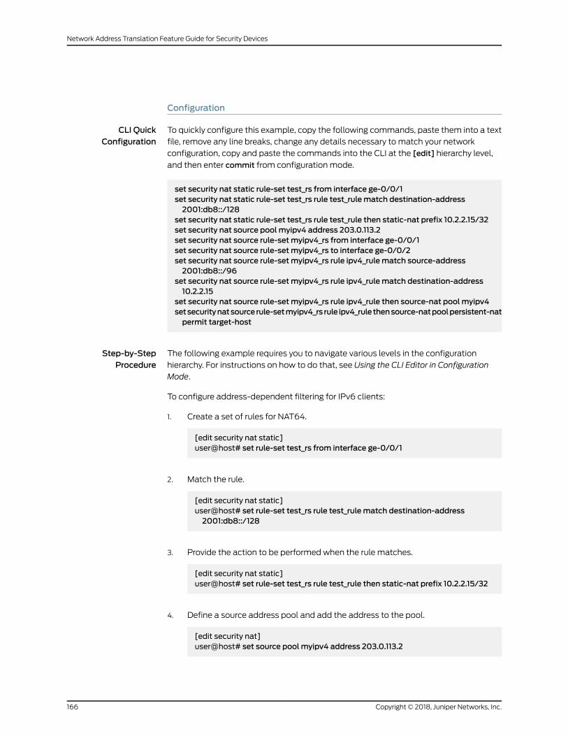
Configuration
CLI QuickConfiguration
To quickly configure this example, copy the following commands, paste them into a text
file, remove any line breaks, change any details necessary to match your network
configuration, copy and paste the commands into the CLI at the [edit] hierarchy level,
and then enter commit from configuration mode.
set security nat static rule-set test_rs from interface ge-0/0/1set security nat static rule-set test_rs rule test_rulematch destination-address2001:db8::/128
set security nat static rule-set test_rs rule test_rule then static-nat prefix 10.2.2.15/32set security nat source pool myipv4 address 203.0.113.2set security nat source rule-setmyipv4_rs from interface ge-0/0/1set security nat source rule-setmyipv4_rs to interface ge-0/0/2set security nat source rule-setmyipv4_rs rule ipv4_rulematch source-address2001:db8::/96
set security nat source rule-setmyipv4_rs rule ipv4_rulematch destination-address10.2.2.15
set security nat source rule-setmyipv4_rs rule ipv4_rule then source-nat pool myipv4setsecuritynatsourcerule-setmyipv4_rs rule ipv4_rulethensource-natpoolpersistent-natpermit target-host
Step-by-StepProcedure
The following example requires you to navigate various levels in the configuration
hierarchy. For instructions on how to do that, see Using the CLI Editor in Configuration
Mode.
To configure address-dependent filtering for IPv6 clients:
1. Create a set of rules for NAT64.
[edit security nat static]user@host# set rule-set test_rs from interface ge-0/0/1
2. Match the rule.
[edit security nat static]user@host# set rule-set test_rs rule test_rulematch destination-address2001:db8::/128
3. Provide the action to be performed when the rule matches.
[edit security nat static]user@host# set rule-set test_rs rule test_rule then static-nat prefix 10.2.2.15/32
4. Define a source address pool and add the address to the pool.
[edit security nat]user@host# set source pool myipv4 address 203.0.113.2
Copyright © 2018, Juniper Networks, Inc.166
Network Address Translation Feature Guide for Security Devices
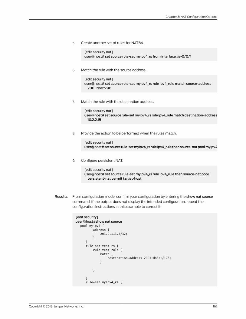
5. Create another set of rules for NAT64.
[edit security nat]user@host# set source rule-setmyipv4_rs from interface ge-0/0/1
6. Match the rule with the source address.
[edit security nat]user@host# set source rule-setmyipv4_rs rule ipv4_rulematch source-address2001:db8::/96
7. Match the rule with the destination address.
[edit security nat]user@host# set source rule-setmyipv4_rs rule ipv4_rulematchdestination-address10.2.2.15
8. Provide the action to be performed when the rules match.
[edit security nat]user@host#setsource rule-setmyipv4_rs rule ipv4_rule thensource-natpoolmyipv4
9. Configure persistent NAT.
[edit security nat]user@host# set source rule-setmyipv4_rs rule ipv4_rule then source-nat poolpersistent-nat permit target-host
Results From configuration mode, confirm your configuration by entering the show nat source
command. If the output does not display the intended configuration, repeat the
configuration instructions in this example to correct it.
[edit security]user@host#show nat source pool myipv4 { address { 203.0.113.2/32; } } rule-set test_rs { rule test_rule { match { destination-address 2001:db8::/128; }
}
} rule-set myipv4_rs {
167Copyright © 2018, Juniper Networks, Inc.
Chapter 3: NAT Configuration Options

from interface ge-0/0/1.0; to interface ge-0/0/2.0; rule ipv4_rule { match { source-address 2001:db8::/96; destination-address 10.2.2.15/32; } then { source-nat { pool { myipv4; persistent-nat { permit target-host; } } } } } }}
If you are done configuring the device, enter commit from configuration mode.
Verification
Confirm that the configuration is working properly:
• Verifying That the Configuration Is Enabled andWorking on page 168
• Verifying That Rules Are Matched and Used on page 168
Verifying That the Configuration Is Enabled andWorking
Purpose Verify that the configuration is enabled and working.
Action From operational mode, enter the following commands:
• show security nat static rule test_rule
• show security nat source rule ipv4_rule
• show security nat source pool myipv4
Verifying That Rules Are Matched and Used
Purpose Verify that all the rules are matched and used.
Action From operational mode, enter the show security nat source persistent-nat-table all
command.
Copyright © 2018, Juniper Networks, Inc.168
Network Address Translation Feature Guide for Security Devices

Example: Configuring Endpoint-Independent Filtering for IPv6 Clients
This example shows how to configure endpoint-independent filtering for IPv6 clients
using NAT64.
• Requirements on page 169
• Overview on page 169
• Configuration on page 169
• Verification on page 172
Requirements
Before you begin:
• Ensure that IPv6 is enabled on the device
• Ensure that the existing NAT rules and pool configuration do not conflict with the new
ones.
Overview
In this example you use NAT64 to send packets from the IPv6 internal host to the IPv4
external host and from the IPv4 external host to the IPv4 internal host.
Configuration
CLI QuickConfiguration
To quickly configure this example, copy the following commands, paste them into a text
file, remove any line breaks, change any details necessary to match your network
configuration, copy and paste the commands into the CLI at the [edit] hierarchy level,
and then enter commit from configuration mode.
set security nat static rule-set test_rs from interface ge-0/0/1set security nat static rule-set test_rs rule test_rulematch destination-address2001:db8::/128
set security nat static rule-set test_rs rule test_rule then static-nat prefix 10.2.2.15/32set security nat source pool myipv4 address 203.0.113.2set security nat source rule-setmyipv4_rs from interface ge-0/0/1set security nat source rule-setmyipv4_rs to interface ge-0/0/2set security nat source rule-setmyipv4_rs rule ipv4_rulematch source-address2001:db8::/96
set security nat source rule-setmyipv4_rs rule ipv4_rulematch destination-address10.2.2.15
set security nat source rule-setmyipv4_rs rule ipv4_rule then source-nat pool myipv4setsecuritynatsourcerule-setmyipv4_rs rule ipv4_rulethensource-natpoolpersistent-natpermit any-remote-host
169Copyright © 2018, Juniper Networks, Inc.
Chapter 3: NAT Configuration Options

Step-by-StepProcedure
The following example requires you to navigate various levels in the configuration
hierarchy. For instructions on how to do that, see Using the CLI Editor in Configuration
Mode.
To configure endpoint-independent filtering for IPv6 clients:
1. Create a set of rules for NAT64.
[edit security nat static]user@host# set rule-set test_rs from interface ge-0/0/1
2. Match the rule.
[edit security nat static]user@host# set rule-set test_rs rule test_rulematch destination-address2001:db8::/128
3. Provide the action to be performed when the rule matches.
[edit security nat static]user@host# set rule-set test_rs rule test_rule then static-nat prefix 10.2.2.15/32
4. Define a source address pool and add the address to the pool.
[edit security nat]user@host# set source pool myipv4 address 203.0.113.2
5. Create another set of rules for NAT64.
[edit security nat]user@host# set source rule-setmyipv4_rs from interface ge-0/0/1
6. Match the rule with the source address.
[edit security nat]user@host# set source rule-setmyipv4_rs rule ipv4_rulematch source-address2001:db8::/96
7. Match the rule with the destination address.
[edit security nat]user@host# set source rule-setmyipv4_rs rule ipv4_rulematchdestination-address10.2.2.15
8. Provide the action to be performed when the rules match.
[edit security nat]
Copyright © 2018, Juniper Networks, Inc.170
Network Address Translation Feature Guide for Security Devices

user@host#setsource rule-setmyipv4_rs rule ipv4_rule thensource-natpoolmyipv4
9. Configure persistent NAT.
[edit security nat]user@host# set source rule-setmyipv4_rs rule ipv4_rule then source-nat poolpersistent-nat permit any-remote-host
Results From configuration mode, confirm your configuration by entering the show nat source
command. If the output does not display the intended configuration, repeat the
configuration instructions in this example to correct it.
[edit security]user@host#show nat source pool myipv4 { address { 203.0.113.2/32; } } rule-set test_rs { rule test_rule { match { destination-address 2001:db8::/128; }
}
} rule-set myipv4_rs { from interface ge-0/0/1.0; to interface ge-0/0/2.0; rule ipv4_rule { match { source-address 2001:db8::/96; destination-address 10.2.2.15/32; } then { source-nat { pool { myipv4; persistent-nat { permit any-remote-host; } } } } } }}
If you are done configuring the device, enter commit from configuration mode.
171Copyright © 2018, Juniper Networks, Inc.
Chapter 3: NAT Configuration Options

Verification
Confirm that the configuration is working properly:
• Verifying That the Configuration is Enabled andWorking on page 172
• Verifying That Rules Are Matched and Used on page 172
Verifying That the Configuration is Enabled andWorking
Purpose Verify that the configuration is enabled and working.
Action From operational mode, enter the following commands.
• show security nat static rule test_rule
• show security nat source rule ipv4_rule
• show security nat source pool myipv4
Verifying That Rules Are Matched and Used
Purpose Verify that all the rules are matched and used.
Action From operational mode, enter the show security nat source persistent-nat-table all
command.
Example: SettingMaximumPersistent NAT Bindings
This example shows how to increase the persistent NAT capacity.
• Requirements on page 172
• Overview on page 172
• Configuration on page 173
• Verification on page 174
Requirements
Before you begin, see “Understanding Persistent NAT and NAT64” on page 151.
Overview
In this example, you enable the maximize persistent NAT capacity option. This option is
supported only on Services Processing Cards (SPCs) for SRX1400 devices with
SRX1K-NPC-SPC-1-10-40, SRX3000 Series devices with SRX3K-SPC-1-10-40, and
SRX5000 Series devices with SRX5K-SPC-2-10-40SPC and SRX5K-SPC3. Note that
for theSRX5000SeriesdeviceswithSRX5K-SPC-2-10-40SPCandSPC3, thepersistent
NATbinding number ismaximized at the cost of reducing themaximumsession number.
To enable this option, the supported central point maximum binding capacity can be
approximately increased to 1/8 of the central point session capacity up to 2M and the
Copyright © 2018, Juniper Networks, Inc.172
Network Address Translation Feature Guide for Security Devices

supported SPUmaximum binding capacity can be approximately increased to 1/4 of
each SPU session capacity. Accordingly, the flow session capacity will decrease by 1/4
on both the CP and each of the SPU.
By default, the persistent NAT binding capacity on both the central point and the SPU
of an SRX5400, SRX5600, or SRX5800 device is 64,000. In this example, you enable
the session capacity to maximum 20,000,000 on the central point andmaximum
1,100,000 on each of the SPUs with maximum session configuration. If you enable the
maximize-persistent-nat-capacity option, an SRX5400, SRX5600, or SRX5800 device
with 4 GB of memory can support maximum 2M persistent NAT bindings on the central
point and 275,000 bindings on each of the SPUs.
Configuration
Step-by-StepProcedure
To increase the persistent NAT capacity:
Set maximize persistent NAT capacity option.1.
[edit]user@host# set security forwarding-process application-servicesmaximize-persistent-nat-capacity
2. If you are done configuring the device, commit the configuration.
[edit]user@host# commit
3. Restart the system from operational mode.
[edit]user@host# request system reboot
NOTE: When switching tomaximize persistent NAT capacity mode orback to regular mode, youmust restart the device.
4. If youwant to switch thedeviceback to regularmode,delete themaximizepersistent
NAT capacity mode configuration.
[edit]user@host# delete security forwarding-process application-servicesmaximize-persistent-nat-capacity
173Copyright © 2018, Juniper Networks, Inc.
Chapter 3: NAT Configuration Options

Verification
Verifying Increased Persistent NAT Capacity
Purpose Verify that you have increased the persistent NAT capacity.
Action From operational mode, enter the show security forwarding-process application-services
command.
Persistent NAT Hairpinning Overview
When traffic is sent between two hosts, the source host of the traffic may only know the
destination host by its public IP address. In reality, the destination host may be in the
same private address space as the source host. Hairpinning is the process of returning
the traffic in the direction fromwhere it came from as a way to get it to its destination
host in a private subnetwork.
Generally, a source host in a subnetwork may not recognize that the traffic is intended
for a destination host within the same subnetwork, because it identifies the destination
host only by its public IP address. TheNAT analyzes the IP packets and routes the packet
back to the correct host.
NAT hairpinning support is required if two hosts on the internal network want to
communicatewith each other by using a binding on the NAT device. In this case, the NAT
device receives a packet from the internal network and forwards it back to the internal
network. If hairpinning is not supported, forwarding the packet will fail and it will be
dropped.
NOTE:
• NAT hairpinning behavior is not supported by target host persistent NATand target host port persistent NAT. Only any remote host persistent NATsupports hairpinning behavior.
• To allow hairpinning, youmust configure a security policy to allow trafficbetween endpoints in the same zone. Actually the two endpoints can belocated in two different zones as well as long as either of the two hostscan only see the public address of the peer.
• Persistent NAT hairpinning applies only to any remote host persistent NATtype.
Example: Configuring Persistent NAT Hairpinning with Source NAT Pool with Address Shifting
This example shows how to configure persistent NAT hairpinning.
Copyright © 2018, Juniper Networks, Inc.174
Network Address Translation Feature Guide for Security Devices

Requirements
Before you begin:
• Configure network interfaces on the device. See Interfaces Feature Guide for Security
Devices.
• Create security zones andassign interfaces to them.SeeUnderstandingSecurity Zones.
Overview
Hairpinning allows packets from the private network to be translated and then looped
back to the private network rather than being passed through to the public network.
Hairpinning feature enables using a corresponding record in the NAT table to recognize
that apacket is addressed toahost in the local network. Then it translates thedestination
IP address and sends the packet back to the local network (as well as in case of port
mapping). This ensures that traffic between the two hosts work properly.
Hairpinning enables two endpoints (Host 1 and Host 2) on the private network to
communicate even if they only use each other’s external IP addresses and ports. This is
explained in Figure 18 on page 176.
When Host 1 sends traffic to Host 3, a NAT binding between Host 1’s internal source IP
address and port is associated in the NAT tablewith its external IP address and port. The
same thing happens when Host 2 sends traffic to Host 3. In this way, when Host 1 and
Host 2 want to communicate, they can identify each other’s external IP addresses.
For example, if Host 1 communicateswith Host 2, NAT (with hairpinning support) is used
to route the packets, which contain Host 2’s external address, back to Host 2’s internal
address.
175Copyright © 2018, Juniper Networks, Inc.
Chapter 3: NAT Configuration Options

Figure 18: Persistent NAT Hairpinning
SRX Series Device
Host 3
198.51.100.2/24
g030
696
198.51.100.254/24
10.10.10.254/24
reth1z zone
Host 1 Host 2
10.10.10.10/2410.10.10.2/24
reth0z zone
Binding 1: 10.10.10.2, 69 192.0.2.1, 69
Binding 2: 10.10.10.10, 69 192.0.2.9, 69
192.0.2.1, 69 10.10.10.10, 6910.10.10.2, 69 192.0.2.9, 69
In Figure 18 on page 176, the following parameters are used:
• Host 1 IP address - 10.10.10.2/24
• Host 2 IP address - 10.10.10.10/24
• Intra-zone IP address - 10.10.10.254/24
• Host 3 IP address - 198.51.100.2/24
• Inter-zone IP address - 198.51.100.254/24
• Host 1 and Host 2 are in zone reht0z, and Host 3 is in reth1z zone
Table 13 on page 176 shows the binding table used in this example.
Table 13: Persistent NAT Binding Table
Translated Source IP AddressOriginal Source IP Address
192.0.2.1/32 to 192.0.2.10/3210.10.10.2/24 to 10.10.10.11/24
Configuration
Step-by-StepProcedure
To configure persistent NAT hairpinning:
Configure interfaces.1.
[edit]user@host# set interfaces ge-11/0/0 unit 0 family inet address 10.10.10.254/24
Copyright © 2018, Juniper Networks, Inc.176
Network Address Translation Feature Guide for Security Devices
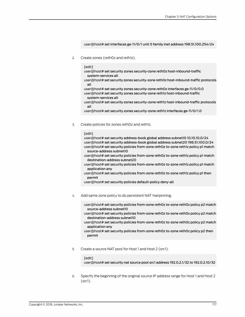
user@host# set interfaces ge-11/0/1 unit 0 family inet address 198.51.100.254/24
2. Create zones (reth0z and reth1z).
[edit]user@host# set security zones security-zone reth0z host-inbound-trafficsystem-services all
user@host# set security zones security-zone reth0z host-inbound-traffic protocolsall
user@host# set security zones security-zone reth0z interfaces ge-11/0/0.0user@host# set security zones security-zone reth1z host-inbound-trafficsystem-services all
user@host# set security zones security-zone reth1z host-inbound-traffic protocolsall
user@host# set security zones security-zone reth1z interfaces ge-11/0/1.0
3. Create policies for zones reth0z and reth1z.
[edit]user@host# set security address-book global address subnet10 10.10.10.0/24user@host# set security address-book global address subnet20 198.51.100.0/24user@host# set security policies from-zone reth0z to-zone reth1z policy p1matchsource-address subnet10
user@host# set security policies from-zone reth0z to-zone reth1z policy p1matchdestination-address subnet20
user@host# set security policies from-zone reth0z to-zone reth1z policy p1matchapplication any
user@host# set security policies from-zone reth0z to-zone reth1z policy p1 thenpermit
user@host# set security policies default-policy deny-all
4. Add same zone policy to do persistent NAT hairpinning.
user@host# set security policies from-zone reth0z to-zone reth0z policy p2matchsource-address subnet10
user@host# set security policies from-zone reth0z to-zone reth0z policy p2matchdestination-address subnet10
user@host# set security policies from-zone reth0z to-zone reth0z policy p2matchapplication any
user@host# set security policies from-zone reth0z to-zone reth0z policy p2 thenpermit
5. Create a source NAT pool for Host 1 and Host 2 (src1).
[edit]user@host# set security nat source pool src1 address 192.0.2.1/32 to 192.0.2.10/32
6. Specify the beginning of the original source IP address range for Host 1 and Host 2
(src1).
177Copyright © 2018, Juniper Networks, Inc.
Chapter 3: NAT Configuration Options

[edit]user@host# set security nat source pool src1 host-address-base 10.10.10.2/24
7. Configure the source NAT rule set r1.
[edit]user@host# set security nat source rule-set r1 from zone reth0zuser@host# set security nat source rule-set r1 to zone reth1zuser@host# set security nat source rule-set r1 to zone reth0zuser@host# set security nat source rule-set r1 rule rule1 match source-address10.10.10.0/24
user@host# set security nat source rule-set r1 rule rule1match destination-address10.10.10.0/24
user@host# set security nat source rule-set r1 rule rule1match destination-address198.51.100.0/24
user@host# set security nat source rule-set r1 rule rule1 then source-nat pool src1user@host# set security nat source rule-set r1 rule rule1 then source-nat poolpersistent-nat permit any-remote-host
user@host# set security nat source rule-set r1 rule rule1 then source-nat poolpersistent-nat inactivity-timeout 900
user@host# set security nat source rule-set r1 rule rule1 then source-nat poolpersistent-natmax-session-number 20
Results From configuration mode, enter the show security nat command to confirm your
configuration. If the output does not display the intended configuration, repeat the
configuration instructions in this example to correct it.
[edit]user@host# show security natsource {pool src1 {address {192.0.2.1/32 to 192.0.2.10/32;
}host-address-base 10.10.10.2/24;
}rule-set r1 {from zone reth0z;to zone [ reth0z reth1z ];rule rule1 {match {source-address 10.10.10.0/24;destination-address [10.10.10.0/24 198.51.100.0/24];
}then {source-nat {pool {src1;persistent-nat {permit any-remote-host;inactivity-timeout 900;
Copyright © 2018, Juniper Networks, Inc.178
Network Address Translation Feature Guide for Security Devices

max-session-number 20;}
}}
}}
}}
If you are done configuring the device, enter commit from configuration mode.
Verification
Traffic Sent Between the Hosts Creating Binding 1
Purpose Verify traffic sent from between the hosts (Host 1 and Host 3) creating binding 1.
Action user@host>show security nat source persistent-nat-table all
sendip -d r28 -p ipv4 -iv 4 -is 10.10.10.2 -id 198.51.100.2 -p udp -us 69 -ud 69 198.51.100.2
Source-IP: 10.10.10.2 Source-port: 69 Dst-IP: 198.51.100.2 Dst-port: 69 Binding1 is below:
Internal Reflective Source Type Left_time/ Curr_Sess_Num/ Source In_IP In_Port Ref_IP Ref_Port NAT Pool Conf_time Max_Sess_Num NAT Rule10.10.10.2 69 192.0.2.1 69 src1 any-remote-host -/900 1/20 rule1
Traffic Sent Between the Hosts Creating Binding 2
Purpose Verify traffic sent from between the hosts (Host 2 and Host 3) creating binding 2.
179Copyright © 2018, Juniper Networks, Inc.
Chapter 3: NAT Configuration Options

Action user@host>show security nat source persistent-nat-table all
sendip -d r28 -p ipv4 -iv 4 -is 10.10.10.10 -id 198.51.100.2 -p udp -us 69 -ud 69 198.51.100.2 Source-IP: 10.10.10.10 Source-port: 69 Dst-IP: 198.51.100.2 Dst-port: 69 Binding2 is below:
Internal Reflective Source Type Left_time/ Curr_Sess_Num/ Source In_IP In_Port Ref_IP Ref_Port NAT Pool Conf_time Max_Sess_Num NAT Rule10.10.10.2 69 192.0.2.1 69 src1 any-remote-host -/900 1/20 rule1 10.10.10.10 69 192.0.2.9 69 src1 any-remote-host -/900 1/20 rule1
Traffic Sent Between Two Hosts
Purpose Verify the traffic sent from Host 1 to Host 2:
Action user@host>show security flow session
sendip -d r28 -p ipv4 -iv 4 -is 10.10.10.2 -id 192.0.2.9 -p udp -us 69 -ud 69 192.0.2.9
Session ID: 100007628, Policy name: default-policy/2, Timeout: 52, Valid In: 10.10.10.2/69 --> 192.0.2.9/69;udp, If: ge-0/0/0.0, Pkts: 2, Bytes: 112 Out: 10.10.10.10/69 --> 192.0.2.1/69;udp, If: ge-0/0/0.0, Pkts: 0, Bytes: 0 Total sessions: 1
NAT for Multicast Flows
To implement multicast group address translation, either static NAT or destination NAT
is used. With the help of NAT, source addresses in IPv4 are translated to IPv4multicast
group destination addresses.
• Understanding NAT for Multicast Flows on page 180
• Example: Configuring NAT for Multicast Flows on page 181
Understanding NAT for Multicast Flows
Network Address Translation (NAT) can be used to translate source addresses in IPv4
multicast flows and to translate IPv4multicast group destination addresses.
Either static NAT or destination NAT can be used to performmulticast group address
translation.StaticNATallowsconnections tobeoriginated fromeither sideof thenetwork,
but translation is limited to one-to-one addresses or between blocks of addresses of the
same size. No address pools are necessary. Use the static configuration statement at
Copyright © 2018, Juniper Networks, Inc.180
Network Address Translation Feature Guide for Security Devices

the [edit security nat] hierarchy level to configure static NAT rule sets formulticast traffic.
Destination NAT allows connections to be initiated only for incoming network
connections—for example, from the Internet to a private network. Use the destination
configuration statement at the [edit security nat] hierarchy level to configure destination
NAT pools and rule sets.
SourceNAT formulticast traffic is supported only by using IP address shifting to translate
the original source IP address to an IP address from a user-defined address pool. This
type of translation is one-to-one, static, and without port address translation. If the
original source IP address range is larger than the IP address range in the user-defined
pool, untranslated packets are dropped. Themapping does not provide bidirectional
mapping, which static NAT provides. Use the source configuration statement at the [edit
security nat] hierarchy level to configure sourceNATpools and rule sets.When youdefine
the source NAT pool for this type of source NAT, use the host-address-base option to
specify the start of the original source IP address range.
See Also Source NAT on page 41•
• Static NAT on page 128
• Destination NAT on page 105
Example: Configuring NAT for Multicast Flows
This example shows how to configure a Juniper Networks device for address translation
of multicast flows.
• Requirements on page 181
• Overview on page 181
• Configuration on page 184
• Verification on page 189
Requirements
Before you begin:
1. Configurenetwork interfaceson thedevice.See the InterfacesFeatureGuide forSecurity
Devices.
2. Create security zonesandassign interfaces to them.SeeUnderstandingSecurity Zones.
3. Configure the device for multicast forwarding.
Overview
This example uses the trust security zone for the private address space and the untrust
security zone for the public address space. Figure 19 on page 183 depicts a typical
deployment of the Juniper Networks device for multicast forwarding. The source router
R1 sends multicast packets with source addresses in the range 203.0.113.100 through
181Copyright © 2018, Juniper Networks, Inc.
Chapter 3: NAT Configuration Options

203.0.113.110 and the group address 233.252.0.1/32 toward the Juniper Networks device.
The source router R1 is in the private network (trust zone) upstream of the Juniper
Networks device. There are several receivers in the public network (untrust zone)
downstream of the device.
The Juniper Networks device translates incomingmulticast packets from R1 before
forwarding themouton thedownstream interfaces.The following translationsareapplied:
• For the interface to R2, the source address is untranslated, and the group address is
translated to 233.252.0.2/32.
• For the interface to R3, the source address is translated to an address in the range
198.51.100.200 through 198.51.100.210, and the group address is translated to
233.252.0.2/32.
• For the interface to R4, the source address is translated to an address in the range
10.10.10.100 through 10.10.10.110, and thegroupaddress is translated to233.252.0.2/32.
Copyright © 2018, Juniper Networks, Inc.182
Network Address Translation Feature Guide for Security Devices

Figure 19: NAT Translations for Multicast Flows
R1
Untrustzone
xe-2/0/1.0SRX Series device
Trustzone
xe-1/0/1.0 xe-2/0/0.0xe-1/0/0.0
R3 R4R2
Private address space
Public address space
From R1 To R2 To R3 To R4
Original Group IP Group IP Group IP Group IP
233.252.0.1/32 233.252.0.2/32 233.252.0.2/32 233.252.0.2/32
Original Source IP Source IP Source IP Source IP
203.0.113.100 - 203.0.113.100 - 198.51.100.200 - 10.10.10.100 -203.0.113.110 203.0.113.110 198.51.100.210 10.10.10.110
g030
689
This example describes the following configurations:
• Destination NAT pool dst-nat-pool that contains the IP address 233.252.0.2/32.
• DestinationNAT rule set rs1with rule r1 tomatchpacketsarrivingon interface xe-2/0/1.0
with the destination IP address 233.252.0.1/32. For matching packets, the destination
address is translated to the IP address in the dst-nat-pool pool.
• Source NAT pool src-nat-shift-1 that contains the IP address range 198.51.100.200/32
through 198.51.100.210/32. For this pool, thebeginningof theoriginal source IPaddress
range is 203.0.113.100/32 and is specified with the host-address-base option.
183Copyright © 2018, Juniper Networks, Inc.
Chapter 3: NAT Configuration Options
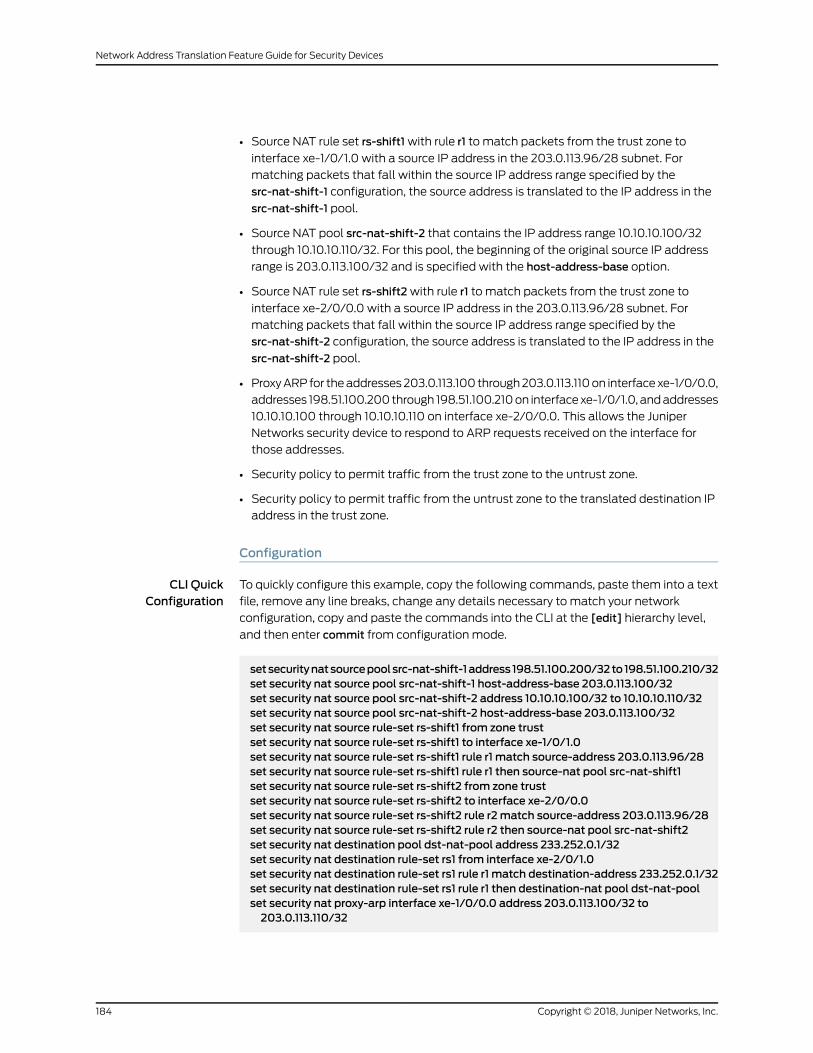
• Source NAT rule set rs-shift1with rule r1 to match packets from the trust zone to
interface xe-1/0/1.0 with a source IP address in the 203.0.113.96/28 subnet. For
matching packets that fall within the source IP address range specified by the
src-nat-shift-1 configuration, the source address is translated to the IP address in the
src-nat-shift-1 pool.
• Source NAT pool src-nat-shift-2 that contains the IP address range 10.10.10.100/32
through 10.10.10.110/32. For this pool, the beginning of the original source IP address
range is 203.0.113.100/32 and is specified with the host-address-base option.
• Source NAT rule set rs-shift2with rule r1 to match packets from the trust zone to
interface xe-2/0/0.0 with a source IP address in the 203.0.113.96/28 subnet. For
matching packets that fall within the source IP address range specified by the
src-nat-shift-2 configuration, the source address is translated to the IP address in the
src-nat-shift-2 pool.
• ProxyARPfor theaddresses203.0.113.100 through203.0.113.110on interfacexe-1/0/0.0,
addresses 198.51.100.200through 198.51.100.210on interfacexe-1/0/1.0, andaddresses
10.10.10.100 through 10.10.10.110 on interface xe-2/0/0.0. This allows the Juniper
Networks security device to respond to ARP requests received on the interface for
those addresses.
• Security policy to permit traffic from the trust zone to the untrust zone.
• Security policy to permit traffic from the untrust zone to the translated destination IP
address in the trust zone.
Configuration
CLI QuickConfiguration
To quickly configure this example, copy the following commands, paste them into a text
file, remove any line breaks, change any details necessary to match your network
configuration, copy and paste the commands into the CLI at the [edit] hierarchy level,
and then enter commit from configuration mode.
setsecuritynatsourcepoolsrc-nat-shift-1address 198.51.100.200/32to198.51.100.210/32set security nat source pool src-nat-shift-1 host-address-base 203.0.113.100/32set security nat source pool src-nat-shift-2 address 10.10.10.100/32 to 10.10.10.110/32set security nat source pool src-nat-shift-2 host-address-base 203.0.113.100/32set security nat source rule-set rs-shift1 from zone trustset security nat source rule-set rs-shift1 to interface xe-1/0/1.0set security nat source rule-set rs-shift1 rule r1 match source-address 203.0.113.96/28set security nat source rule-set rs-shift1 rule r1 then source-nat pool src-nat-shift1set security nat source rule-set rs-shift2 from zone trustset security nat source rule-set rs-shift2 to interface xe-2/0/0.0set security nat source rule-set rs-shift2 rule r2match source-address 203.0.113.96/28set security nat source rule-set rs-shift2 rule r2 then source-nat pool src-nat-shift2set security nat destination pool dst-nat-pool address 233.252.0.1/32set security nat destination rule-set rs1 from interface xe-2/0/1.0set security nat destination rule-set rs1 rule r1 match destination-address 233.252.0.1/32set security nat destination rule-set rs1 rule r1 then destination-nat pool dst-nat-poolset security nat proxy-arp interface xe-1/0/0.0 address 203.0.113.100/32 to203.0.113.110/32
Copyright © 2018, Juniper Networks, Inc.184
Network Address Translation Feature Guide for Security Devices

set security nat proxy-arp interface xe-1/0/1.0 address 198.51.100.200/32 to198.51.100.210/32
set security natproxy-arp interfacexe-2/0/0.0address 10.10.10.100/32 to 10.10.10.110/32set security policies from-zone trust to-zone untrust policy internet-accessmatchsource-address any
set security policies from-zone trust to-zone untrust policy internet-accessmatchdestination-address any
set security policies from-zone trust to-zone untrust policy internet-accessmatchapplication any
set security policies from-zone trust to-zone untrust policy internet-access then permitset security policies from-zone untrust to-zone trust policy dst-nat-pool-accessmatchsource-address any
set security policies from-zone untrust to-zone trust policy dst-nat-pool-accessmatchdestination-address 233.252.0.1/21
set security policies from-zone untrust to-zone trust policy dst-nat-pool-accessmatchapplication any
set security policies from-zone untrust to-zone trust policy dst-nat-pool-access thenpermit
Step-by-StepProcedure
The following example requires you to navigate various levels in the configuration
hierarchy. For instructions on how to do that, see Using the CLI Editor in Configuration
Mode.
To configure the destination and source NAT translations for multicast flows:
1. Create a destination NAT pool.
[edit security nat destination]user@host# set pool dst-nat-pool address 233.252.0.1/32
2. Create a destination NAT rule set.
[edit security nat destination]user@host# set rule-set rs1 from interface xe-2/0/1.0
3. Configure a rule that matches packets and translates the destination address to
the address in the destination NAT pool.
[edit security nat destination]user@host# set rule-set rs1 rule r1 match destination-address 233.252.0.1/32user@host# set rule-set rs1 rule r1 then destination-nat pool dst-nat-pool
4. Create a source NAT pool.
[edit security nat source]user@host# set pool src-nat-shift-1 address 198.51.100.200 to 198.51.100.210
5. Specify the beginning of the original source IP address range.
185Copyright © 2018, Juniper Networks, Inc.
Chapter 3: NAT Configuration Options
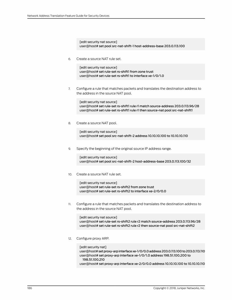
[edit security nat source]user@host# set pool src-nat-shift-1 host-address-base 203.0.113.100
6. Create a source NAT rule set.
[edit security nat source]user@host# set rule-set rs-shift1 from zone trustuser@host# set rule-set rs-shift1 to interface xe-1/0/1.0
7. Configure a rule that matches packets and translates the destination address to
the address in the source NAT pool.
[edit security nat source]user@host# set rule-set rs-shift1 rule r1 match source-address 203.0.113.96/28user@host# set rule-set rs-shift1 rule r1 then source-nat pool src-nat-shift1
8. Create a source NAT pool.
[edit security nat source]user@host# set pool src-nat-shift-2 address 10.10.10.100 to 10.10.10.110
9. Specify the beginning of the original source IP address range.
[edit security nat source]user@host# set pool src-nat-shift-2 host-address-base 203.0.113.100/32
10. Create a source NAT rule set.
[edit security nat source]user@host# set rule-set rs-shift2 from zone trustuser@host# set rule-set rs-shift2 to interface xe-2/0/0.0
11. Configure a rule that matches packets and translates the destination address to
the address in the source NAT pool.
[edit security nat source]user@host# set rule-set rs-shift2 rule r2match source-address 203.0.113.96/28user@host# set rule-set rs-shift2 rule r2 then source-nat pool src-nat-shift2
12. Configure proxy ARP.
[edit security nat]user@host#setproxy-arp interfacexe-1/0/0.0address203.0.113.100to203.0.113.110user@host# set proxy-arp interface xe-1/0/1.0 address 198.51.100.200 to198.51.100.210
user@host# set proxy-arp interface xe-2/0/0.0 address 10.10.10.100 to 10.10.10.110
Copyright © 2018, Juniper Networks, Inc.186
Network Address Translation Feature Guide for Security Devices

13. Configurea security policy that allows traffic fromthe trust zone to theuntrust zone.
[edit security policies from-zone trust to-zone untrust]user@host# set policy internet-accessmatch source-address anydestination-address any application any
user@host# set policy internet-access then permit
14. Configurea security policy that allows traffic fromtheuntrust zone to the trust zone.
[edit security policies from-zone untrust to-zone trust]user@host# set policy dst-nat-pool-accessmatch source-address anydestination-address 233.252.0.1/32 application any
user@host# set policy dst-nat-pool-access then permit
Results From configuration mode, confirm your configuration by entering the show security nat
and show security policies commands. If the output does not display the intended
configuration, repeat the configuration instructions in this example to correct it.
[edit]user@host# show security natsource {pool src-nat-shift-1 {address {198.51.100.200/32 to 198.51.100.210/32;
}host-address-base 203.0.113.100/32;
}pool src-nat-shift-2 {address {10.10.10.100/32 to 10.10.10.110/32;
}host-address-base 203.0.113.100/32;
}rule-set trust-to-untrust {from zone trust;to zone untrust;rule source-nat-rule {match {source-address 0.0.0.0/0;
}then {source-nat {interface;
}}
}}rule-set rs-shift1 {from zone trust;to interface xe-1/0/1.0;rule r1 {
187Copyright © 2018, Juniper Networks, Inc.
Chapter 3: NAT Configuration Options

match {source-address 203.0.113.96/28;
}then {source-nat {pool {src-nat-shift1;
}}
}}
}rule-set rs-shift2 {from zone trust;to interface xe-2/0/0.0;rule r2 {match {source-address 203.0.113.96/28;
}then {source-nat {pool {src-nat-shift2;
}}
}}
}}destination {pool dst-nat-pool {address 233.252.0.1/32;
}rule-set rs1 {from interface xe-2/0/1.0;rule r1 {match {destination-address 233.252.0.1/32;
}then {destination-nat pool dst-nat-pool;
}}
}}proxy-arp {interface xe-1/0/0.0 {address {203.0.113.100/32 to 203.0.113.110/32;
}}interface xe-1/0/1.0 {address {198.51.100.200/32 to 198.51.100.210/32;
}
Copyright © 2018, Juniper Networks, Inc.188
Network Address Translation Feature Guide for Security Devices

}interface xe-2/0/0.0 {address {10.10.10.100/32 to 10.10.10.110/32;
}}
}
[edit]user@host# show security policiesfrom-zone trust to-zone untrust {policy trust-to-untrust {match {source-address any;destination-address any;application any;
}then {permit;
}}policy internet-access {match {source-address any;destination-address any;application any;
}then {permit;
}}from-zone untrust to-zone trust {policy dst-nat-pool-access {match {source-address any;destination-address 233.252.0.1/21;application any;
}then {permit;
}}
}}
If you are done configuring the device, enter commit from configuration mode.
Verification
To confirm that the configuration is working properly, perform these tasks:
• Verifying Destination NAT Pool Usage on page 190
• Verifying Destination NAT Rule Usage on page 190
189Copyright © 2018, Juniper Networks, Inc.
Chapter 3: NAT Configuration Options

• Verifying Source NAT Pool Usage on page 190
• Verifying Source NAT Rule Usage on page 190
• Verifying NAT Application to Traffic on page 190
Verifying Destination NAT Pool Usage
Purpose Verify that there is traffic using IP addresses from the destination NAT pool.
Action From operational mode, enter the show security nat destination pool all command. View
the Translation hits field to check for traffic using IP addresses from the pool.
Verifying Destination NAT Rule Usage
Purpose Verify that there is traffic matching the destination NAT rule.
Action From operational mode, enter the show security nat destination rule all command. View
the Translation hits field to check for traffic that matches the rule.
Verifying Source NAT Pool Usage
Purpose Verify that there is traffic using IP addresses from the source NAT pool.
Action From operational mode, enter the show security nat source pool all command. View the
Translation hits field to check for traffic using IP addresses from the pool.
Verifying Source NAT Rule Usage
Purpose Verify that there is traffic matching the source NAT rule.
Action From operational mode, enter the show security nat source rule all command. View the
Translation hits field to check for traffic that matches the rule.
Verifying NAT Application to Traffic
Purpose Verify that NAT is being applied to the specified traffic.
Action From operational mode, enter the show security flow session command.
Copyright © 2018, Juniper Networks, Inc.190
Network Address Translation Feature Guide for Security Devices

IPv6 NAT
IPv6 NAT helps to translate IPv4 addresses to IPv6 addresses of network devices. IPv6
NAT also helps to translate the address between IPv6 hosts. IPv6 NAT supports source
NAT, destination NAT, and static NAT.
• IPv6 NAT Overview on page 191
• IPv6 NAT PT Overview on page 193
• IPv6 NAT-PT Communication Overview on page 194
• Example: Configuring an IPv4-Initiated Connection to an IPv6 Node Using Default
Destination Address Prefix Static Mapping on page 194
• Example: Configuring an IPv4-Initiated Connection to an IPv6 Node Using Static
Destination Address One-to-One Mapping on page 198
• Example: Configuring an IPv6-Initiated Connection to an IPv4 Node Using Default
Destination Address Prefix Static Mapping on page 201
• Example: Configuring an IPv6-Initiated Connection to an IPv4 Node Using Static
Destination Address One-to-One Mapping on page 206
IPv6 NATOverview
IPv6hasavastly largeraddressspace than the impendingexhausted IPv4addressspace.
IPv4 has been extended using techniques such as Network Address Translation (NAT),
whichallows for rangesof private addresses tobe representedbya single public address,
and temporary address assignment. There are a lot of technologies to provide the
transition mechanism for the legacy IPv4 host to keep the connection to the Internet.
IPv6NATprovidesaddress translationbetween IPv4and IPv6addressednetworkdevices.
It also provides address translation between IPv6 hosts. NATbetween IPv6 hosts is done
in a similar manner and for similar purposes as IPv4 NAT.
IPv6 NAT in Junos OS provides the following NAT types:
• Source NAT
• Destination NAT
• Static NAT
Source NAT Translations Supported by IPv6 NAT
Source NAT is the translation of the source IP address of a packet leaving the Juniper
Networks device. Source NAT is used to allow hosts with private IP addresses to access
a public network.
IPv6 NAT in Junos OS supports the following source NAT translations:
• Translationofone IPv6subnet toanother IPv6subnetwithoutport address translation
• Translation of IPv4 addresses to IPv6 prefix + IPv4 addresses
• Translation of IPv6 hosts to IPv6 hosts with or without port address translation
191Copyright © 2018, Juniper Networks, Inc.
Chapter 3: NAT Configuration Options
• Translation of IPv6 hosts to IPv4 hosts with or without port address translation
• Translation of IPv4 hosts to IPv6 hosts with or without port address translation
Destination NATMappings Supported by IPv6 NAT
Destination NAT is the translation of the destination IP address of a packet entering the
Juniper Networks device. Destination NAT is used to redirect traffic destined to a virtual
host (identified by the original destination IP address) to the real host (identified by the
translated destination IP address).
IPv6 NAT in Junos OS supports the following destination NAT translations:
• Prefix translation between IPv4 and IPv6 prefix
• Mapping of one IPv6 subnet to another IPv6 subnet
• Mapping of one IPv6 subnet to an IPv6 host
• Mapping of one IPv6 subnet to one IPv4 subnet
• Mapping of one IPv4 subnet to one IPv6 subnet
• Mapping of one IPv6 host (and optional port number) to one special IPv6 host (and
optional port number)
• Mapping of one IPv6 host (and optional port number) to one special IPv4 host (and
optional port number)
• Mapping of one IPv4 host (and optional port number) to one special IPv6 host (and
optional port number)
Static NATMappings Supported by IPv6 NAT
Static NAT defines a one-to-onemapping from one IP subnet to another IP subnet. The
mapping includesdestination IPaddress translation inonedirectionandsource IPaddress
translation in the reverse direction. From theNATdevice, the original destination address
is the virtual host IP address while the mapped-to address is the real host IP address.
IPv6 NAT in Junos OS supports the following static NAT translations:
• Translation of one IPv6 subnet to another IPv6 subnet
• Translation of one IPv6 host to another IPv6 host
• Translation of one IPv4 address a.b.c.d to IPv6 address Prefix::a.b.c.d
• Translation of IPv4 hosts to IPv6 hosts
See “Example: Configuring an IPv4-InitiatedConnection to an IPv6NodeUsingDefault
Destination Address Prefix Static Mapping” on page 194.
• Translation of IPv6 hosts to IPv4 hosts
See “Example: Configuring an IPv6-InitiatedConnection to an IPv4NodeUsingDefault
Destination Address Prefix Static Mapping” on page 201.
• Mapping of one IPv6 prefix to one IPv4 prefix
Copyright © 2018, Juniper Networks, Inc.192
Network Address Translation Feature Guide for Security Devices

See “Example: Configuring an IPv6-Initiated Connection to an IPv4 Node Using Static
Destination Address One-to-One Mapping” on page 206.
• Mapping of one IPv4 prefix to one IPv6 prefix
See “Example: Configuring an IPv4-Initiated Connection to an IPv6 Node Using Static
Destination Address One-to-One Mapping” on page 198.
• Mapping of one iPv6 prefix to one IPv6 prefix
IPv6 NAT PTOverview
IPv6 Network Address Translation-Protocol Translation (NAT-PT) provides address
allocation and protocol translation between IPv4 and IPv6 addressed network devices.
The translation process is based on the Stateless IP/ICMP Translation (SIIT) method;
however, the stateand thecontextof eachcommunicationare retainedduring thesession
lifetime. IPv6 NAT-PT supports Internet Control Message Protocol (ICMP), TCP, and
UDP packets.
IPv6 NAT-PT supports the following types of NAT-PT:
• Traditional NAT-PT—In traditional NAT-PT, the sessions are unidirectional and
outbound from the IPv6 network . Traditional NAT-PT allows hosts within an IPv6
network to access hosts in an IPv4 network. There are two variations to traditional
NAT-PT: basic NAT-PT and NAPT-PT.
In basic NAT-PT, a block of IPv4 addresses at an IPv4 interface is set aside for
translating addresses as IPv6 hosts as they initiate sessions to the IPv4 hosts. The
basic NAT-PT translates the source IP address and related fields such as IP, TCP, UDP,
and ICMPheader checksums forpacketsoutbound fromthe IPv6domain . For inbound
packets, it translates the the destination IP address and the checksums.
Network Address Port Translation-Protocol Translation (NAPT-PT) can be combined
with basicNAT-PT so that a pool of external addresses is used in conjunctionwith port
translation.NAPT-PTallowsasetof IPv6hosts toshareasingle IPv4address.NAPT-PT
translates the source IP address, source transport identifier, and related fields such as
IP,TCP,UDP,and ICMPheaderchecksums, forpacketsoutbound fromthe IPv6network.
The transport identifier can be a TCP/UDP port or an ICMP query ID. For inbound
packets, it translates the destination IP address, destination transport identifier, and
the IP and the transport header checksums.
• Bidirectional NAT-PT—In bidirectional NAT-PT, sessions can be initiated from hosts
in the IPv4 network as well as the IPv6 network. IPv6 network addresses are bound to
IPv4addresses, either statically ordynamically as connectionsareestablished ineither
direction. The static configuration is similar to static NAT translation. Hosts in IPv4
realm access hosts in the IPv6 realm using DNS for address resolution. A DNS ALG
must be employed in conjunction with bidirectional NAT-PT to facilitate
name-to-address mapping. Specifically, the DNS ALGmust be capable of translating
IPv6addresses inDNSqueries and responses into their IPv4addressbindings, and vice
versa, as DNS packets traverse between IPv6 and IPv4 realms.
193Copyright © 2018, Juniper Networks, Inc.
Chapter 3: NAT Configuration Options

NOTE: The SRX Series devices partially support the bidirectional NAT-PTspecification. It supports flow of bidirectional traffic assuming that thereare other ways to convey themapping between the IPv6 address and thedynamically allocated IPv4 address. For example, a local DNS can beconfiguredwith themappedentries for IPv4nodesto identify theaddresses.
NAT- PT Operation—The SRX Series devices support the traditional NAT-PT and allow
staticmapping for theuser tocommunicate from IPv4 to IPv6 .Theuserneeds tostatically
configure the DNS server with an IPv4 address for the hostname and then create a static
NAT on the device for the IPv6-only node to communicate from an IPv4-only node to an
IPv6-only node based on the DNS.
IPv6 NAT-PT Communication Overview
NAT-PT communication with static mapping—Network Address Translation-Protocol
Translation (NAT-PT) can be done in two directions, from IPv6 to IPv4 and vice versa.
For each direction, static NAT is used tomap the destination host to a local address and
a source address NAT is used to translate the source address. There are two types of
static NAT and source NATmapping: one-to-onemapping and prefix-basedmapping.
NAT- PT communication with DNS ALG—ADNS-basedmechanism dynamically maps
IPv6 addresses to IPv4-only servers. NAT-PT uses the DNS ALG to transparently do the
translations. For example, a company using an internal IPv6 network needs to be able
to communicate with external IPv4 servers that do not yet have IPv6 addresses.
To support the dynamic address binding, a DNS should be used for name resolution. The
IPv4 host looks up the name of the IPv6 node in its local configured IPv4 DNS server,
which then passes the query to the IPv6 DNS server through an SRX Series device using
NAT-PT.
The DNS ALG in NAT device :
• Translates the IPv6 address resolution back to IPv4 address resolution.
• Allocates an IPv6 address for the mapping.
• Stores amapping of the allocated IPv4 address to the IPv6 address returned in the
IPv6 address resolution so that the session can be established from any-IPv4 hosts to
the IPv6 host.
Example: Configuring an IPv4-Initiated Connection to an IPv6 Node Using Default DestinationAddress Prefix Static Mapping
This example shows how to configure an IPv4-initiated connection to an IPv6 node using
default destination address prefix static mapping.
• Requirements on page 195
• Overview on page 195
Copyright © 2018, Juniper Networks, Inc.194
Network Address Translation Feature Guide for Security Devices

• Configuration on page 195
• Verification on page 198
Requirements
Before you begin, configure interfaces and assign them to security zones.
Overview
The following example describes how to configure an IPv4-initiated connection to an
IPv6 node that has a staticmapping 126-based IPv6 address defined on its interface and
staticmapping /126 set up on the device. This example assumes that the IPv6 addresses
tobemapped to IPv4addressesmake the IPv4addressespartof the IPv6address space.
Configuring an IPv4-initiated connection to an IPv6 node is useful when the devices on
the IPv4 networkmust be interconnected to the devices on the IPv6 network and during
migration of an IPv4 network to an IPv6 network. Themapping can be used for DNSALG
for reverse lookup of IPv4 addresses from IPv6 addresses, for the traffic initiated from
the IPv6 network. This process also provides connectivity for sessions initiated from IPv4
nodes with IPv6 nodes on the other side of the NAT/PT device.
Configuration
CLI QuickConfiguration
To quickly configure this example, copy the following commands, paste them into a text
file, remove any line breaks, change any details necessary to match your network
configuration, copy and paste the commands into the CLI at the [edit] hierarchy level,
and then enter commit from configuration mode.
set security nat static rule-set test_rs from interface ge-0/0/1.0setsecuritynatstatic rule-set test_rs rule test_rulematchdestination-address 10.1.1.45/30set security nat static rule-set test_rs rule test_rule then static-nat prefix 2001:db8::/64set security nat source pool myipv6_prefix address 2001:db8::/64set security nat source rule-setmyipv6_rs from interface ge-0/0/1.0set security nat source rule-setmyipv6_rs to interface ge-0/0/2.0setsecuritynatsource rule-setmyipv6_rs rule ipv6_rulematchsource-address 10.1.1.0/30set security nat source rule-setmyipv6_rs rule ipv6_rulematch destination-address2001:db8:1a:1112::20/64
setsecuritynatsourcerule-setmyipv6_rs rule ipv6_rulethensource-natpoolmyipv6_prefix
Step-by-StepProcedure
The following example requires you to navigate various levels in the configuration
hierarchy. For instructions on how to do that, see Using the CLI Editor in Configuration
Mode in the CLI User Guide.
Toconfigurean IPv4-initiatedconnection toan IPv6nodeusing static destinationaddress
one-to-onemapping:
1. Configure the static NAT rule set for an interface.
[edit security nat static]user@host# set rule-set test_rs from interface ge-0/0/1.0
195Copyright © 2018, Juniper Networks, Inc.
Chapter 3: NAT Configuration Options

2. Define the rule to match the destination address prefix.
NOTE: The destination address number in thematch rule must be anumber equal to the static-nat prefix range.
There is no limitation on the source address number in thematch rule.
[edit security nat static rule-set test_rs]user@host# set rule test_rulematch destination-address 10.1.1.45/30
3. Define the static NAT prefix for the device.
[edit security nat static rule-set test_rs]user@host# set rule test_rule then static-nat prefix 2001:db8::/64
4. Configure the source NAT pool with an IPv6 address prefix.
[edit security nat source]user@host# set pool myipv6_prefix address 2001:db8::/64
5. Configure the source NAT rule set for the interface.
[edit security nat source]user@host# set rule-setmyipv6_rs from interface ge-0/0/1.0user@host# set rule-setmyipv6_rs to interface ge-0/0/2.0
6. Configure the IPv6 source NAT source address.
NOTE: Thesourceaddressnumber in thematch rulemustbeanaddressnumber equal to the source pool range. For example, ^2(32 – 30) =2^(128 – 126) =>.
There is no limitation on the destination address number in thematchrule.
[edit security nat source rule-set myipv6_rs]user@host# set rule ipv6_rulematch source-address 10.1.1.0/30
7. Configure the IPv6 source NAT destination address.
[edit security nat source rule-set myipv6_rs]user@host# set rule ipv6_rulematch destination-address 2001:db8:1a:1112::20/64
Copyright © 2018, Juniper Networks, Inc.196
Network Address Translation Feature Guide for Security Devices

8. Define the configured source NAT IPv6 pool in the rule.
[edit security nat source rule-set myipv6_rs]user@host# set rule ipv6_rule then source-nat pool myipv6_prefix
Results From configuration mode, confirm your configuration by entering the show security nat
command. If the output does not display the intended configuration, repeat the
configuration instructions in this example to correct it.
source {pool myipv6_prefix {address {2001:db8::/64;
}}rule-set myipv6_rs {from interface ge-0/0/1.0;;to interface ge-0/0/2.0;rule ipv6_rule {match {source-address 10.1.1.0/30;destination-address 2001:db8:1a:1112::20/64;
}then {source-nat {pool {myipv6_prefix;
}}
}}
}}static {rule-set test_rs {from interface ge-0/0/1.0;rule test_rule {match {destination-address 10.1.1.45/30;
}then {static-nat {prefix {2001:db8::/64;
}}
}}
}}
If you are done configuring the device, enter commit from configuration mode.
197Copyright © 2018, Juniper Networks, Inc.
Chapter 3: NAT Configuration Options

Verification
To confirm that the configuration is working properly, perform these tasks:
• Verifying That Static NAT Is Configured on page 198
• Verifying That Source NAT Is Configured on page 198
Verifying That Static NAT Is Configured
Purpose Verify whether static NAT is configured with an interface, a destination address, and a
prefix.
Action From operational mode, enter the show security nat static command.
Verifying That Source NAT Is Configured
Purpose Verify whether source NAT is configured.
Action From operational mode, enter the show security nat source command.
Example: Configuring an IPv4-Initiated Connection to an IPv6 Node Using Static DestinationAddress One-to-OneMapping
This example shows how to configure an IPv4-initiated connection to an IPv6 node using
static destination address one-to-onemapping.
• Requirements on page 198
• Overview on page 198
• Configuration on page 199
• Verification on page 201
Requirements
Before you begin, configure the interfaces and assign the interfaces to security zones.
Overview
The following example describes how to configure an IPv4 node to communicate with
an IPv6 node using one-to-one static NAT on the device.
The communication of an IPv4 nodewith an IPv6 node is useful for IPv4 hosts accessing
an IPv6 server, for new servers that support IPv6 only and that need to be connected to
the IPv6 network, and for migrating of old hosts to the new server whenmost of the
machines have already moved to IPv6. For example, you can use this feature to connect
an IPv4-only node to an IPv6-only printer. This mapping can also be used for DNS ALG
for reverse lookup of IPv4 addresses from IPv6 addresses for traffic that is initiated from
the IPv6 network.
Copyright © 2018, Juniper Networks, Inc.198
Network Address Translation Feature Guide for Security Devices

Configuration
CLI QuickConfiguration
To quickly configure this example, copy the following commands, paste them into a text
file, remove any line breaks, change any details necessary to match your network
configuration, copy and paste the commands into the CLI at the [edit] hierarchy level,
and then enter commit from configuration mode.
set security nat static rule-set test_rs from interface ge-0/0/1set securitynatstatic rule-set test_rs rule test_rulematchdestination-address 10.1.1.25/32setsecuritynatstatic rule-set test_rs rule test_rule thenstatic-natprefix2001:db8::25/128set security nat source pool myipv6_prefix address 2001:db8::/96set security nat source rule-setmyipv6_rs from interface ge-0/0/1set security nat source rule-setmyipv6_rs to interface ge-0/0/2set security nat source rule-setmyipv6_rs rule ipv6_rulematch source-address10.10.10.1/30
set security nat source rule-setmyipv6_rs rule ipv6_rulematch destination-address2001:db8::25
setsecuritynatsourcerule-setmyipv6_rs rule ipv6_rulethensource-natpoolmyipv6_prefix
Step-by-StepProcedure
The following example requires you to navigate various levels in the configuration
hierarchy. For instructions on how to do that, see Using the CLI Editor in Configuration
Mode.
Toconfigurean IPv4-initiatedconnection toan IPv6nodeusing static destinationaddress
one-to-onemapping:
1. Configure the static NAT rule set for an interface.
[edit security nat static]user@host# set rule-set test_rs from interface ge-0/0/1
2. Define the rule and the destination address.
[edit security nat static rule-set test_rs]user@host# set rule test_rulematch destination-address 10.1.1.25/32
3. Define the static NAT prefix.
[edit security nat static rule-set test_rs]user@host# set rule test_rule then static-nat prefix 2001:db8::25/128
4. Configure a source NAT pool with an IPv6 prefix address.
[edit security]user@host# set nat source pool myipv6_prefix address 2001:db8::/96
5. Configure the source NAT rule set.
199Copyright © 2018, Juniper Networks, Inc.
Chapter 3: NAT Configuration Options

[edit security nat source]user@host# set rule-setmyipv6_rs from interface ge-0/0/1user@host# set rule-setmyipv6_rs from interface ge-0/0/2
6. Configure the source NAT source address.
[edit security nat source rule-set myipv6_rs]user@host# set rule ipv6_rulematch source-address 10.10.10.1/30
7. Configure the source NAT destination address.
[edit security nat source rule-set myipv6_rs]user@host# set rule ipv6_rulematch destination-address 2001:db8::25
8. Define a configured source NAT IPv6 pool in the rule.
[edit security nat source rule-set myipv6_rs]user@host# set rule ipv6_rule then source-nat pool myipv6_prefix
Results From configuration mode, confirm your configuration by entering the show security nat
command. If the output does not display the intended configuration, repeat the
configuration instructions in this example to correct it.
[edit]user@host# show security natsource {pool myipv6_prefix {address {2001:db8::/96;
}}rule-set myipv6_rs {from interface ge-0/0/1.0;to interface ge-0/0/2.0;rule ipv6_rule {match {source-address 10.10.10.1/30;destination-address 2001:db8::25;
}then {source-nat {pool {myipv6_prefix;
}}
}}
}}
Copyright © 2018, Juniper Networks, Inc.200
Network Address Translation Feature Guide for Security Devices
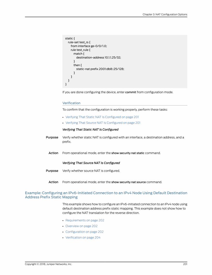
static {rule-set test_rs {from interface ge-0/0/1.0;rule test_rule {match {destination-address 10.1.1.25/32;
}then {static-nat prefix 2001:db8::25/128;
}}
}}
If you are done configuring the device, enter commit from configuration mode.
Verification
To confirm that the configuration is working properly, perform these tasks:
• Verifying That Static NAT Is Configured on page 201
• Verifying That Source NAT Is Configured on page 201
Verifying That Static NAT Is Configured
Purpose Verify whether static NAT is configured with an interface, a destination address, and a
prefix.
Action From operational mode, enter the show security nat static command.
Verifying That Source NAT Is Configured
Purpose Verify whether source NAT is configured.
Action From operational mode, enter the show security nat source command.
Example: Configuring an IPv6-Initiated Connection to an IPv4 Node Using Default DestinationAddress Prefix Static Mapping
This example shows how to configure an IPv6-initiated connection to an IPv4 node using
default destination address prefix static mapping. This example does not show how to
configure the NAT translation for the reverse direction.
• Requirements on page 202
• Overview on page 202
• Configuration on page 202
• Verification on page 204
201Copyright © 2018, Juniper Networks, Inc.
Chapter 3: NAT Configuration Options

Requirements
Before you begin, configure the interfaces and assign the interfaces to security zones.
Overview
The following example describes the communication of an IPv6 nodewith an IPv4 node
that has prefix-based static NAT defined on the device. The static NAT assumes that
the IPv4 network is a special IPv6 network (that is, an IPv4-mapped IPv6 network), and
hides the entire IPv4 network behind an IPv6 prefix.
The communication of an IPv6 nodewith an IPv4 node is useful when IPv6 is used in the
network andmust be connected to the IPv4 network, or when both IPv4 and IPv6 are
used in thenetworkandamechanism is required to interconnect the twonetworksduring
migration. This also provides connectivity for sessions initiated from IPv6 nodes with
IPv4 nodes on the other side of the NAT/PT device.
Configuration
CLI QuickConfiguration
To quickly configure this example, copy the following commands, paste them into a text
file, remove any line breaks, change any details necessary to match your network
configuration, copy and paste the commands into the CLI at the [edit] hierarchy level,
and then enter commit from configuration mode.
set security nat static rule-set test_rs from interface ge-0/0/1set security nat static rule-set test_rs rule test_rulematch destination-address2001:db8::1/96
set security nat static rule-set test_rs rule test_rule then static-nat inetset security nat source pool myipv4 address 203.0.113.2 to 203.0.113.5set security nat source rule-setmyipv4_rs from interface ge-0/0/1set security nat source rule-setmyipv4_rs to interface ge-0/0/2set security nat source rule-setmyipv4_rs rule ipv4_rulematch destination-address10.1.1.15/30
set security nat source rule-setmyipv4_rs rule ipv4_rulematch source-address2001:db8::2/96
set security nat source rule-setmyipv4_rs rule ipv4_rule then source-nat pool myipv4
Step-by-StepProcedure
The following example requires you to navigate various levels in the configuration
hierarchy. For instructions on how to do that, see Using the CLI Editor in Configuration
Mode.
To configure an IPv6-initiated connection to an IPv4 node using default destination
address prefix static mapping:
1. Configure the static NAT for an interface.
[edit security nat static]user@host# set rule test_rs from interface ge-0/0/1
2. Define the rule anddestination addresswith the prefix for the staticNAT translation
defined on the device.
Copyright © 2018, Juniper Networks, Inc.202
Network Address Translation Feature Guide for Security Devices

[edit security nat static rule-set test_rs]user@host# set rule test_rulematch destination-address 2001:db8::1/96
3. Define the static NAT as inet to translate to an IPv4 address.
[edit security nat static rule-set test_rs]user@host# set rule test_rule then static-nat inet
4. Configure the IPv4 source NAT pool address.
[edit security nat source]user@host# set pool myipv4 address 203.0.113.2 to 203.0.113.5
5. Configure the source NAT rule set.
[edit security nat source ]user@host# set rule-setmyipv4_rs from interface ge-0/0/1user@host# set rule-setmyipv4_rs from interface ge-0/0/2
6. Configure the IPv4 source NAT destination address.
[edit security nat source rule-set myipv4_rs]user@host# set rule ipv4_rulematch destination-address 10.1.1.15/30
7. Define the source address with the prefix for the source NAT defined on the device.
[edit security nat source rule-set myipv4_rs]user@host# set rule ipv4_rulematch source-address 2001:db8::/96
8. Define a configured source NAT IPv4 pool in the rule.
[edit security nat source rule-set myipv4_rs]user@host# sset rule ipv4_rule then source-nat pool myipv4
Results From configuration mode, confirm your configuration by entering the show security nat
command. If the output does not display the intended configuration, repeat the
configuration instructions in this example to correct it.
[edit]user@host# show security natsource {pool myipv4 {address {203.0.113.2/32 to 203.0.113.5/32;
}
203Copyright © 2018, Juniper Networks, Inc.
Chapter 3: NAT Configuration Options
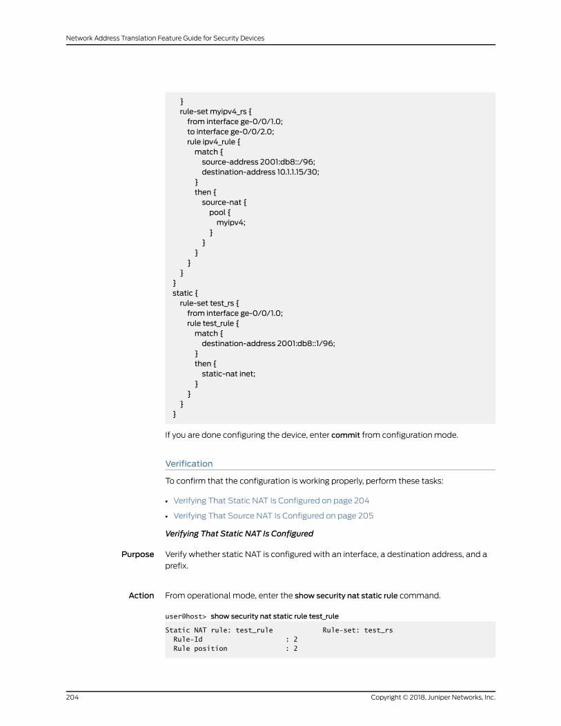
}rule-set myipv4_rs {from interface ge-0/0/1.0;to interface ge-0/0/2.0;rule ipv4_rule {match {source-address 2001:db8::/96;destination-address 10.1.1.15/30;
}then {source-nat {pool {myipv4;
}}
}}
}}static {rule-set test_rs {from interface ge-0/0/1.0;rule test_rule {match {destination-address 2001:db8::1/96;
}then {static-nat inet;
}}
}}
If you are done configuring the device, enter commit from configuration mode.
Verification
To confirm that the configuration is working properly, perform these tasks:
• Verifying That Static NAT Is Configured on page 204
• Verifying That Source NAT Is Configured on page 205
Verifying That Static NAT Is Configured
Purpose Verify whether static NAT is configured with an interface, a destination address, and a
prefix.
Action From operational mode, enter the show security nat static rule command.
user@host> show security nat static rule test_rule
Static NAT rule: test_rule Rule-set: test_rs Rule-Id : 2 Rule position : 2
Copyright © 2018, Juniper Networks, Inc.204
Network Address Translation Feature Guide for Security Devices

From interface : ge-0/0/1.0 Destination addresses : 2001:db8::1 Host addresses : 0.0.0.0 Netmask : 96 Host routing-instance : N/A Translation hits : 0 Successful sessions : 0 Failed sessions : 0 Number of sessions : 0
Verifying That Source NAT Is Configured
Purpose Verify whether source NAT is configured.
Action From operational mode, enter the show security nat source rule command.
user@host> show security nat source rule ipv4_rule
source NAT rule: ipv4_rule Rule-set: myipv4_rs Rule-Id : 2 Rule position : 2 From interface : ge-0/0/1.0 To interface : ge-0/0/2.0 Match Source addresses : 2001:db8:: - 2001:db8::ffff:ffff Destination addresses : 10.1.1.15 - 10.1.1.15 Action : myipv4 Persistent NAT type : N/A Persistent NAT mapping type : address-port-mapping Inactivity timeout : 0 Max session number : 0 Translation hits : 0 Successful sessions : 0 Failed sessions : 0 Number of sessions : 0
From operational mode, enter the show security nat source pool command.
user@host> show security nat source pool myipv4
Pool name : myipv4Pool id : 5Routing instance : defaultHost address base : 0.0.0.0Port : [1024, 63487] Twin port : [63488, 65535]Port overloading : 1Address assignment : no-pairedTotal addresses : 4Translation hits : 0Address range Single Ports Twin Ports 203.0.113.2 - 203.0.113.5 0 0
205Copyright © 2018, Juniper Networks, Inc.
Chapter 3: NAT Configuration Options

Example: Configuring an IPv6-Initiated Connection to an IPv4 Node Using Static DestinationAddress One-to-OneMapping
This example shows how to configure an IPv6-initiated connection to an IPv4 node using
static destination address one-to-onemapping.
• Requirements on page 206
• Overview on page 206
• Configuration on page 206
• Verification on page 208
Requirements
Before you begin, configure the interfaces and assign the interfaces to security zones.
Overview
The following example describes the communication of an IPv6 nodewith an IPv4 node
that has a one-to-one static NAT address defined on the device. The communication of
an IPv6 nodewith an IPv4 node allows IPv6 hosts to access an IPv4 server when neither
of the devices has a dual stack andmust depend on theNAT/PTdevice to communicate.
This enables some IPv4 legacy server applications to work even after the network has
migrated to IPv6.
Configuration
CLI QuickConfiguration
To quickly configure this example, copy the following commands, paste them into a text
file, remove any line breaks, change any details necessary to match your network
configuration, copy and paste the commands into the CLI at the [edit] hierarchy level,
and then enter commit from configuration mode.
set security nat static rule test_rs from interface ge-0/0/1set security nat static rule test_rs rule test_rulematch destination-address2001:db8::15/128
set security nat static rule test_rs rule test_rule then static-nat prefix 10.2.2.15/32set security nat source pool myipv4 address 203.0.113.2 to 203.0.113.3set security nat source rulemyipv4_rs from interface ge-0/0/1set security nat source rulemyipv4_rs to interface ge-0/0/2setsecuritynatsource rulemyipv4_rs rule ipv4_rulematchsource-address2001:db8::/96set security nat source rulemyipv4_rs rule ipv4_rulematch destination-address 10.2.2.15set security nat source rulemyipv4_rs rule ipv4_rule then source-nat pool myipv4
Step-by-StepProcedure
The following example requires you to navigate various levels in the configuration
hierarchy. For instructions on how to do that, see Using the CLI Editor in Configuration
Mode.
Toconfigurean IPv6-initiatedconnection toan IPv4nodeusing static destinationaddress
one-to-onemapping:
1. Configure the static NAT rule set for an interface.
Copyright © 2018, Juniper Networks, Inc.206
Network Address Translation Feature Guide for Security Devices
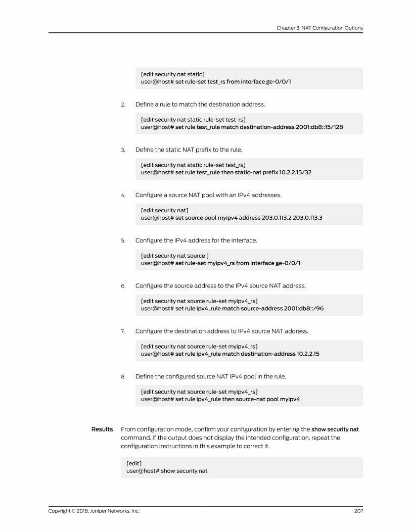
[edit security nat static]user@host# set rule-set test_rs from interface ge-0/0/1
2. Define a rule to match the destination address.
[edit security nat static rule-set test_rs]user@host# set rule test_rulematch destination-address 2001:db8::15/128
3. Define the static NAT prefix to the rule.
[edit security nat static rule-set test_rs]user@host# set rule test_rule then static-nat prefix 10.2.2.15/32
4. Configure a source NAT pool with an IPv4 addresses.
[edit security nat]user@host# set source pool myipv4 address 203.0.113.2 203.0.113.3
5. Configure the IPv4 address for the interface.
[edit security nat source ]user@host# set rule-setmyipv4_rs from interface ge-0/0/1
6. Configure the source address to the IPv4 source NAT address.
[edit security nat source rule-set myipv4_rs]user@host# set rule ipv4_rulematch source-address 2001:db8::/96
7. Configure the destination address to IPv4 source NAT address.
[edit security nat source rule-set myipv4_rs]user@host# set rule ipv4_rulematch destination-address 10.2.2.15
8. Define the configured source NAT IPv4 pool in the rule.
[edit security nat source rule-set myipv4_rs]user@host# set rule ipv4_rule then source-nat pool myipv4
Results From configuration mode, confirm your configuration by entering the show security nat
command. If the output does not display the intended configuration, repeat the
configuration instructions in this example to correct it.
[edit]user@host# show security nat
207Copyright © 2018, Juniper Networks, Inc.
Chapter 3: NAT Configuration Options
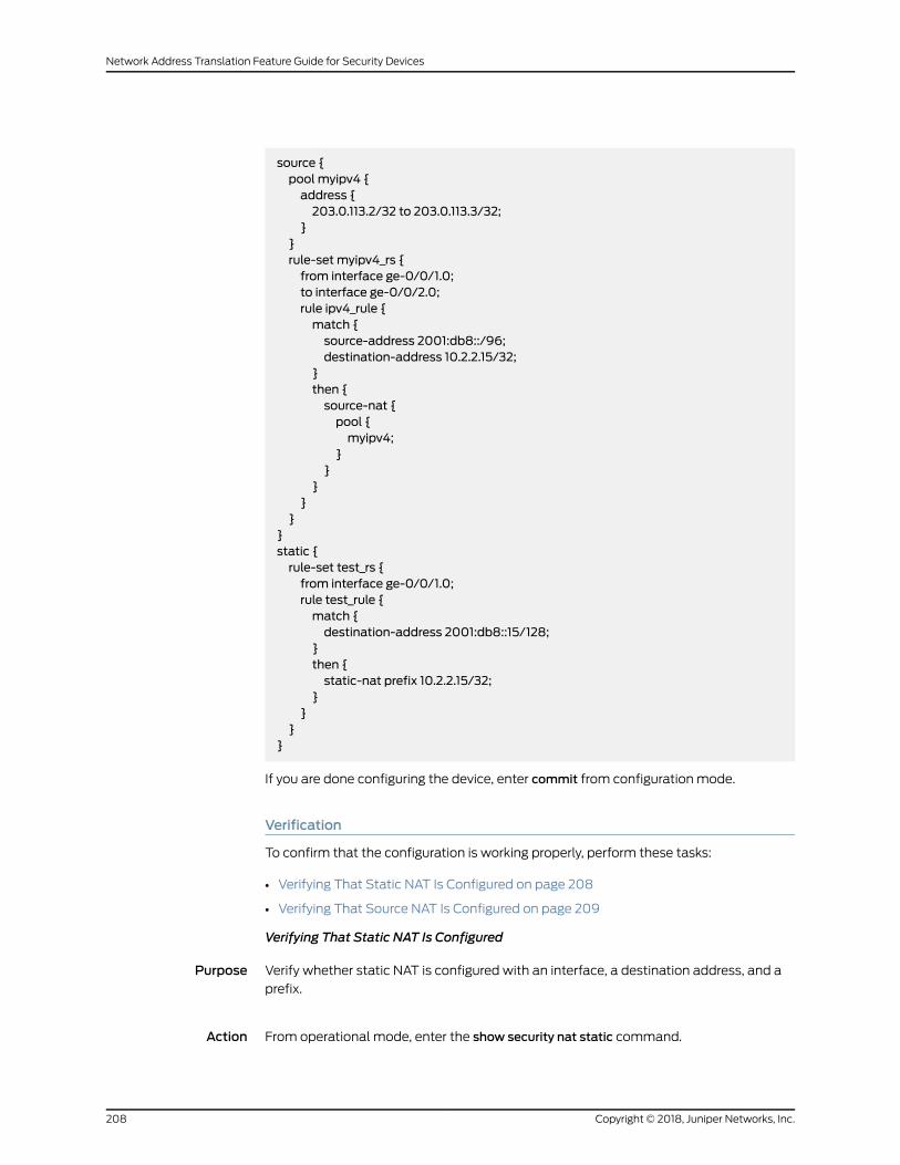
source {pool myipv4 {address {203.0.113.2/32 to 203.0.113.3/32;
}}rule-set myipv4_rs {from interface ge-0/0/1.0;to interface ge-0/0/2.0;rule ipv4_rule {match {source-address 2001:db8::/96;destination-address 10.2.2.15/32;
}then {source-nat {pool {myipv4;
}}
}}
}}static {rule-set test_rs {from interface ge-0/0/1.0;rule test_rule {match {destination-address 2001:db8::15/128;
}then {static-nat prefix 10.2.2.15/32;
}}
}}
If you are done configuring the device, enter commit from configuration mode.
Verification
To confirm that the configuration is working properly, perform these tasks:
• Verifying That Static NAT Is Configured on page 208
• Verifying That Source NAT Is Configured on page 209
Verifying That Static NAT Is Configured
Purpose Verify whether static NAT is configured with an interface, a destination address, and a
prefix.
Action From operational mode, enter the show security nat static command.
Copyright © 2018, Juniper Networks, Inc.208
Network Address Translation Feature Guide for Security Devices

Verifying That Source NAT Is Configured
Purpose Verify whether source NAT is configured.
Action From operational mode, enter the show security nat source command.
RelatedDocumentation
Source NAT on page 41•
• Destination NAT on page 105
• Static NAT on page 128
IPv6 Dual-Stack Lite
IPv6Dual-StackLite (DS-Lite) is a technology tohelp Internet serviceproviders tomigrate
to an IPv6 access network without changing end-user software. IPv4 users continue to
access IPv4 internet content with minimum disruption to their home networks while
enabling IPv6 users to access IPv6 content.
• Understanding IPv6 Dual-Stack Lite on page 209
• Example: Configuring IPv6 Dual-Stack Lite on page 212
Understanding IPv6 Dual-Stack Lite
IPv6 dual-stack lite (DS-Lite) is a technology that enables Internet service providers to
move to an IPv6 network while simultaneously handling IPv4 address depletion.
IPv4 addresses are becoming depleted; therefore, broadband service providers (DSL,
cable, andmobile) need new addresses to support new users. Providing IPv6 addresses
alone is oftennotworkablebecausemostof the systems thatmakeup thepublic Internet
are still enabled and support only IPv4, andmany users’ systems do not yet fully support
IPv6.
DS-Lite allows service providers to migrate to an IPv6 access network without changing
end-user software. Thedevice thataccesses the Internet remains the same, thusallowing
IPv4 users to continue accessing IPv4 internet content with minimum disruption to their
home networks, while enabling IPv6 users to access IPv6 content.
Figure 20 on page 210 illustrates the DS-Lite architecture which uses IPv6-only links
between the provider and the user while maintaining the IPv4 (or dual-stack) hosts in
the user network.
209Copyright © 2018, Juniper Networks, Inc.
Chapter 3: NAT Configuration Options

Figure 20: DS-Lite NAT (IPv4-in-IPv6)
g034
200
192.0.2.1
2001:db8::2
2001:db8::2
2001:db8::1
198.51.100.1
198.51.100.1
192.0.2.1
2001:db8::1
192.0.2.1
192.0.2.1
The DS-Lite deployment model consists of the following components:
Copyright © 2018, Juniper Networks, Inc.210
Network Address Translation Feature Guide for Security Devices

• Softwire initiator for the DS-Lite home router--Encapsulates the IPv4 packet and
transmits it across an IPv6 tunnel.
• Softwire concentrator for DS-Lite carrier-grade Network Address Translation
(NAT)–Decapsulates the IPv4-in-IPv6 packet and also performs IPv4-IPv4 NAT
translations.
When a user’s device sends an IPv4 packet to an external destination, DS-Lite
encapsulates the IPv4 packet in an IPv6 packet for transport into the provider network.
These IPv4-in-IPv6 tunnels are called softwires. Tunneling IPv4 over IPv6 is simpler than
translation and eliminates performance and redundancy concerns.
The softwires terminate in a softwire concentrator at some point in the service provider
network, which decapsulates the IPv4 packets and sends them through a carrier-grade
Network Address Translation (NAT) device. There, the packets undergo source NAT
processing to hide the original source address.
IPv6packetsoriginatedbyhosts in thesubscriber’s homenetworkare transportednatively
over the access network.
TheDS-Lite carrier-gradeNAT translates IPv4-to-IPv4addresses tomultiple subscribers
through a single global IPv4 address. Overlapping address spaces used by subscribers
are disambiguated through the identification of tunnel endpoints. One concentrator can
be the endpoint of multiple softwires.
The IPv4 packets originated by the end hosts have private (and possibly overlapping) IP
addresses.Therefore,NATmustbeapplied to thesepackets. If endhostshaveoverlapping
addresses, Network Address Port Translation (NAPT) is needed.
Using NAPT, the system adds the source address of the encapsulating IPv6 packet in
the subscriber network to the inside IPv4 source address and port. Because each user’s
IPv6 address is unique, the combination of the IPv6 source address with the IPv4 source
address and port creates an unambiguous mapping.
The system takes the following actions when it receives a responding IPv4 packet from
outside the subscriber network:
• Encapsulates the IPv4 packet in an IPv6 packet using themapped IPv6 address as the
IPv6 destination address.
• Forwards the packet to the user.
Table 14 on page 211 lists the maximum number of softwire initiators and softwire
concentrators per device. Platform support depends on the Junos OS release in your
installation.
Table 14: Softwire Initiator and Softwire Concentrator Capacity
SRX5400SRX5600SRX5800
SRX4600SRX4100SRX4200
SRX3400SRX3600
SRX1500SRX650Description
100,000200,000200,000100,00030050,000Maximum softwire initiatorsconnected per device
211Copyright © 2018, Juniper Networks, Inc.
Chapter 3: NAT Configuration Options

Table 14: Softwire Initiator and Softwire Concentrator Capacity (continued)
323232323232Maximum softwireconcentrator numbers perdevice
NOTE: Themost recent IETF draft documentation for DS-Lite uses newterminology:
• The term softwire initiator has been replaced by B4.
• The term softwire concentrator has been replaced by AFTR.
Junos OS documentation generally uses the original terms when discussingconfiguration in order to be consistent with the CLI statements used toconfigure DS-Lite.
For more information, see the following documents:
• draft-ietf-softwire-dual-stack-lite-06, Dual-Stack Lite Broadband Deployments
Following IPv4 Exhaustion, August 2010.
• RFC 2473, Generic Packet Tunneling in IPv6 Specification, December 1998.
• RFC2663, IPNetworkAddressTranslator (NAT)TerminologyandConsiderations, August
1999.
• RFC 4787, Network Address Translation (NAT) Behavioral Requirements for Unicast
UDP, BCP 127, January 2007.
• RFC 4925, Softwire Problem Statement, July 2007.
• RFC 5382, NAT Behavioral Requirements for TCP, BCP 142, October 2008.
• RFC 5508, NAT Behavioral Requirements for ICMP, BCP 148, April 2009.
• http://www.potaroo.net/tools/ipv4/index.html
• http://www.iana.org/assignments/ipv4-address-space/ipv4-address-space.xhtml
Example: Configuring IPv6 Dual-Stack Lite
When an ISP begins to allocate IPv6 addresses and IPv6-capable equipment to new
subscriber homes, dual-stack lite (DS-Lite) provides amethod for the private IPv4
addressesbehind the IPv6CEWANequipment to reach the IPv4network.DS-Liteenables
IPv4 customers to continue to access the Internet using their current hardware by using
a softwire initiator at the customer edge to encapsulate IPv4 packets into IPv6 packets
withminimumdisruption to their homenetwork,while enabling IPv6customers toaccess
IPv6 content. The softwire concentrator decapsulates the IPv4-in-IPv6 packets and also
performs IPv4-IPv4 NAT translations.
Copyright © 2018, Juniper Networks, Inc.212
Network Address Translation Feature Guide for Security Devices

This example shows you how to configure a softwire concentrator for IPv4-in-IPv6
addresses.
• Requirements on page 213
• Overview on page 213
• Configuration on page 213
• Verification on page 214
Requirements
Before you begin:
• Review the overview section on DS-Lite. See “Understanding IPv6 Dual-Stack Lite” on
page 209.
• Reviewhow ICMPv6packetsarehandledby theSRXSeriesdevices. SeeUnderstanding
How SRX Series Devices Handle ICMPv6 Packets.
Overview
This configuration example shows how to configure a softwire concentrator, the softwire
name, the concentrator address, and the softwire type.
NOTE: The softwire concentrator IPv6 address canmatch an IPv6 addressconfiguredonaphysical interfaceoran IPv6addressconfiguredona loopbackinterface.
Configuration
CLI QuickConfiguration
To quickly configure this example, copy the following commands, paste them into a text
file, remove any line breaks, change any details necessary to match your network
configuration, and then copy andpaste the commands into theCLI at the [edit]hierarchy
level, and then enter commit from configuration mode.
set security softwires softwire-namemy_sc1 softwire-concentrator 2001:db8::1softwire-type IPv4-in-IPv6
Step-by-StepProcedure
The following example requires you to navigate various levels in the configuration
hierarchy. For instructions on how to do that, see Using the CLI Editor in Configuration
Mode in theCLI User Guide.
To configure a DS-Lite softwire concentrator to convert IPv4 packets into IPv6 packets:
1. Assign a name for the softwire concentrator.
[edit security]user@host# edit softwires softwire-namemy_sc1
213Copyright © 2018, Juniper Networks, Inc.
Chapter 3: NAT Configuration Options

2. Specify the address of the softwire concentrator.
[edit security softwires softwire-namemy_sc1]user@host# set softwire-concentrator 2001:db8::1
3. Specify the softwire type for IPv4 to IPv6.
[edit security softwires softwire-namemy_sc1 softwire-concentrator 2001:db8::1user@host# set softwire-type IPv4-in-IPv6
Results From configuration mode, confirm your configuration by entering the show command. If
the output does not display the intended configuration, repeat the instructions in this
example to correct the configuration.
[edit security softwires softwire-namemy_sc1]user@host# showsoftwire-concentrator 2001:db8::1;softwire-type ipv4-in-ipv6;
If you are done configuring the device, enter commit from configuration mode.
Verification
From operational mode, enter the show security softwires command. If a softwire is not
connected, the operational output looks like the following sample:
user@host# show security softwiresSoftwire Name SC Address Status Number of SI connected my-sc1 2001:db8::1 Active 0
If a softwire is connected, the operational output looks like the following sample:
user@host# show security softwiresSoftwire Name SC Address Status Number of SI connected my-sc1 2001:db8::1 Connected 1
RelatedDocumentation
• Understanding IPv6 Address Space, Addressing, Address Format, and Address Types
• Understanding How SRX Series Devices Handle ICMPv6 Packets
• About the IPv6 Basic Packet Header
Copyright © 2018, Juniper Networks, Inc.214
Network Address Translation Feature Guide for Security Devices
CHAPTER 4
Configuration Statements
• address (Security ARP Proxy) on page 218
• address (Security Destination NAT) on page 218
• address (Security NDP Proxy) on page 219
• address-mapping on page 220
• address-persistent (Security Source NAT) on page 220
• address-persistent (Security Source NAT Pool) on page 221
• address-pooling (Security Source NAT) on page 222
• address-shared (Security Source NAT) on page 223
• application (Security Destination NAT) on page 224
• application (Security Source NAT) on page 225
• application-services (Security Forwarding Process) on page 226
• clear-threshold on page 227
• description (Security NAT Pool) on page 228
• description (Security NAT Rule) on page 229
• description (Security NAT Rule Set) on page 230
• destination (Security Destination NAT) on page 231
• destination-address (Security Destination NAT) on page 232
• destination-address (Security Source NAT) on page 233
• destination-address (Security Static NAT) on page 233
• destination-address-name (Security Destination NAT) on page 234
• destination-address-name (Security Source NAT) on page 234
• destination-address-name (Security Static NAT) on page 235
• destination-nat on page 236
• destination-port (Security Destination NAT) on page 237
• destination-port (Security Source NAT) on page 238
• destination-port (Security Static NAT) on page 239
• enable-reroute-uniform-link-check on page 240
• from (Security NAT) on page 241
215Copyright © 2018, Juniper Networks, Inc.

• host-address-base on page 241
• inactivity-timeout (Security Persistent NAT) on page 242
• inet (Security Static NAT) on page 243
• interface (Security NAT ARP Proxy) on page 244
• interface (Security NAT NDP Proxy) on page 245
• interface (Security Source NAT) on page 246
• interface (Security Source NAT Rule Set) on page 246
• interim-logging-interval on page 247
• last-block-recycle-timeout on page 248
• mapped-port (Security Static NAT) on page 249
• match (Security Destination NAT) on page 250
• match (Security Source NAT) on page 251
• match (Security Static NAT) on page 252
• max-session-number on page 252
• overflow-pool on page 253
• nptv6-prefix on page 254
• nptv6-prefix-name on page 254
• permit (Security Persistent NAT) on page 255
• persistent-nat on page 256
• pool (Security Destination NAT) on page 257
• pool (Security Source NAT) on page 258
• pool (Security Source NAT Rule Set) on page 259
• pool-default-port-range on page 260
• pool-default-twin-port-range on page 261
• pool-utilization-alarm on page 262
• pool-utilization-alarm (Security Source NAT Pool) on page 263
• port (Security Source NAT) on page 264
• port-overloading (Security Source NAT Interface) on page 265
• port-overloading-factor (Security Source NAT Interface) on page 266
• port-overloading-factor (Security Source NAT Pool) on page 267
• port-randomization on page 268
• port-round-robin on page 268
• port-scaling-enlargement on page 269
• prefix (Security Static NAT) on page 270
• prefix-name (Security Static NAT) on page 271
• protocol (Security Destination NAT) on page 272
• protocol (Security Source NAT) on page 272
Copyright © 2018, Juniper Networks, Inc.216
Network Address Translation Feature Guide for Security Devices

• proxy-arp (Security NAT) on page 273
• proxy-ndp (Security NAT) on page 274
• raise-threshold on page 274
• routing-instance (Security Destination NAT) on page 275
• routing-instance (Security Source NAT) on page 275
• rule (Security Destination NAT) on page 276
• rule (Security Source NAT) on page 277
• rule (Security Static NAT) on page 279
• rule-session-count-alarm (Security Destination NAT Rule Set) on page 280
• rule-session-count-alarm (Security Source NAT Rule Set) on page 281
• rule-session-count-alarm (Security Static NAT Rule Set) on page 282
• rule-set (Security Destination NAT) on page 283
• rule-set (Security Source NAT) on page 285
• rule-set (Security Static NAT) on page 287
• source (Security Source NAT) on page 289
• session-drop-hold-down on page 291
• session-persistence-scan on page 292
• source-address (Security Destination NAT) on page 292
• source-address (Security Source NAT) on page 293
• source-address (Security Static NAT Rule Set) on page 293
• source-address-name (Security Destination NAT) on page 294
• source-address-name (Security Source NAT) on page 294
• source-address-name (Security Static NAT Rule Set) on page 295
• source-nat on page 296
• source-port (Security Source NAT Rule Set) on page 297
• source-port (Security Static NAT Rule Set) on page 297
• static (Security NAT) on page 298
• static-nat on page 299
• to (Security Source NAT) on page 300
• then (Security Destination NAT) on page 301
• then (Security Source NAT) on page 302
• then (Security Static NAT) on page 303
• traceoptions (Security NAT) on page 304
217Copyright © 2018, Juniper Networks, Inc.
Chapter 4: Configuration Statements

address (Security ARP Proxy)
Syntax address ip-address < to ip-address>;
Hierarchy Level [edit security nat proxy-arp interface interface-name],
Release Information Statement modified in Junos OS Release 9.6.
Description Specify a single address or an address range of ARP proxy.
Options to—Specify the upper limit of the address range.
ip-address—IP address of an ARP proxy.
Required PrivilegeLevel
security—To view this statement in the configuration.
security-control—To add this statement to the configuration.
address (Security Destination NAT)
Syntax address <ip-address> {(port port-number | to ip-address);
}
Hierarchy Level [edit security nat destination pool pool-name]
Release Information Statement modified in Junos OS Release 9.6.
Description Specify a single address or an address range of the destination NAT pool.
Options • ip-address—IP address of a pool.
• port port-number—Specify the port number.
• to—Specify the upper limit of the address range.
Required PrivilegeLevel
security—To view this statement in the configuration.
security-control—To add this statement to the configuration.
Copyright © 2018, Juniper Networks, Inc.218
Network Address Translation Feature Guide for Security Devices

address (Security NDP Proxy)
Syntax address ip-address {to ip-address;
}
Hierarchy Level [edit security nat proxy-ndp interface interface-name],
Release Information Statement modified in Junos OS Release 9.6.
Description Specify a single address or an address range of NDP proxy.
Options • ip-address—IP address of an NDP proxy.
• to—Specify the upper limit of the address range.
Required PrivilegeLevel
security—To view this statement in the configuration.
security-control—To add this statement to the configuration.
RelatedDocumentation
219Copyright © 2018, Juniper Networks, Inc.
Chapter 4: Configuration Statements

address-mapping
Syntax address-mapping;
Hierarchy Level [edit security nat source rule-set ruleset rule rule then source-nat interface persistent-nat][edit security nat source rule-set ruleset rule rule then source-nat pool persistent-nat]
Release Information Statement introduced in Junos OS Release 10.2.
Description Allows requests from a specific internal IP address to bemapped to the same reflexive
IP address (the public IP address created by the NAT device closest to the STUN server);
internal and external ports can be any ports. An external host using any port can send a
packet to the internal host by sending the packet to the reflexive IP address (with a
configured incoming policy that allows external to internal traffic). If this option is not
configured, the persistent NAT binding is for specific internal and reflexive transport
addresses.
You can only specify this option when the persistent NAT type is any-remote-host and
the source NAT rule action is one of the following:
• Source NAT pool with IP address shifting
• Source NAT pool with no port translation and no overflow pool
Required PrivilegeLevel
security—To view this statement in the configuration.
security-control—To add this statement to the configuration
address-persistent (Security Source NAT)
Syntax address-persistent;
Hierarchy Level [edit security nat source]
Release Information Statement modified in Junos OS Release 9.2.
Description Enable the device to assign the same, statically chosen, IP address from a source pool
to a host for multiple sessions that require the same source IP address for each session.
This option is a global configuration and is applied to all source pools. After a session is
established from a host and NAT is performed, the subsequent session from the same
host will always use the same translated address.
Required PrivilegeLevel
security—To view this statement in the configuration.
security-control—To add this statement to the configuration.
Copyright © 2018, Juniper Networks, Inc.220
Network Address Translation Feature Guide for Security Devices

address-persistent (Security Source NAT Pool)
Syntax address-persistent subscriber ipv6-prefix-length prefix-length;
Hierarchy Level [edit security nat source pool pool-name]
Release Information Statement introduced in Junos OS Release 12.3X48-D10.
Description Enable the device to translate an IPv6 address, with a consistent IPv6 prefix, to the same
IPv4 address to ensure that IPv4 services can be used over IPv6-only networks.
Options ipv6-prefix-length prefix-length—Specify the subscriber IPv6 prefix length.
Range: 8 through 128.
Required PrivilegeLevel
security—To view this statement in the configuration.
security-control—To add this statement to the configuration.
RelatedDocumentation
• Understanding NAT64 IPv6 Prefix to IPv4 Address-Persistent Translation on page 154
221Copyright © 2018, Juniper Networks, Inc.
Chapter 4: Configuration Statements

address-pooling (Security Source NAT)
Syntax address-pooling (paired | no-paired);
Hierarchy Level [edit security nat source pool pool-name]
Release Information Statement introduced in Junos OS Release 12.1X45-D10.
Description The address-pooling paired and address-pooling no-paired options in a source NAT pool
enable you to override the global address-persistent configuration and to control the IP
addressing in the pool. When either address pooling-paired or address-pooling no-paired
is configured in a NAT source pool, the address-persistent configuration is disabled for
that pool.
Use the address-pooling paired option in source NAT pools with port translation for
applications that require all sessions associated with one internal IP address to be
translated to the same external IP address for multiple sessions. (The default behavior
for a source NAT pool with port translation pools is address-pooling no-paired.)
Use the address-pooling no-paired option in source NAT pools without port translation
for assigning IP addresses using a round-robin fashion. (Thedefault behavior for a source
NAT pool without port translation is address-pooling paired.)
Options no-paired—Allow address-pooling no-paired
paired—Allow address-pooling paired
Required PrivilegeLevel
security—To view this statement in the configuration.
security-control—To add this statement to the configuration.
RelatedDocumentation
• Understanding Source NAT Pools with Address Pooling on page 80
Copyright © 2018, Juniper Networks, Inc.222
Network Address Translation Feature Guide for Security Devices

address-shared (Security Source NAT)
Syntax address-shared;
Hierarchy Level [edit security nat source pool pool-name]
Release Information Statement introduced in Junos OS Release 12.1X45-D10.
Description Specifies that multiple internal IP addresses can bemapped to the same external IP
address. Use this option only when the source NAT pool is configured with no port
translation.
WhenasourceNATpool configuredwithnoport translationhas fewexternal IPaddresses
available, or only oneexternal IPaddress, theaddress-sharedoption,with amany-to-one
mapping, increases NAT resources and improves traffic.
Required PrivilegeLevel
security—To view this statement in the configuration
security-control—To add this statement to the configuration
RelatedDocumentation
• Understanding Shared Addresses in Source NAT Pools without PAT on page 101
• Example: ConfiguringaSingle IPAddress in aSourceNATPoolWithoutPATonpage92
223Copyright © 2018, Juniper Networks, Inc.
Chapter 4: Configuration Statements

application (Security Destination NAT)
Syntax application {[application];any;
}
Hierarchy Level [edit security nat destination rule-set rule-set-name rule rule-namematch]
Release Information Statement introduced in Junos OS Release 12.1X47-D10.
Description Specify an application name tomatch the rule. You can specify multiple application
names, but the number of application termsmust not exceed 3072.
Options application-name—Name of the application.
Required PrivilegeLevel
security—To view this statement in the configuration.
security-control—To add this statement to the configuration.
RelatedDocumentation
• application (Security Policies)
Copyright © 2018, Juniper Networks, Inc.224
Network Address Translation Feature Guide for Security Devices

application (Security Source NAT)
Syntax application {[application];any;
}
Hierarchy Level [edit security nat source rule-set rule-set-name rule rule-namematch]
Release Information Statement introduced in Junos OS Release 12.1X47-D10.
Description Specify an application name tomatch the rule. You can specify multiple application
names, but the number of application termsmust not exceed 3072.
Options application-name—Name of the application.
Required PrivilegeLevel
security—To view this statement in the configuration.
security-control—To add this statement to the configuration.
RelatedDocumentation
• application (Security Policies)
225Copyright © 2018, Juniper Networks, Inc.
Chapter 4: Configuration Statements

application-services (Security Forwarding Process)
Syntax application-services {enable-gtpu-distribution;maximize-alg-sessions;maximize-idp-sessions {weight (firewall | idp);
}packet-ordering-mode {(hardware | software);
}}
Hierarchy Level [edit security forwarding-process]
Release Information Statement introduced in Junos OS Release 9.6. Statement updated in Junos OS Release
10.4. Statement updated in Junos OS Release 15.1X49-D40with the
enable-gtpu-distribution option.
Description You can configure SRX4100, SRX4200, SRX5400, SRX5600, and SRX5800 devices to
switch froman integrated firewallmode tomaximize Intrusion Detection and Prevention
(IDP) mode to run IDP processing in tapmode and increase the capacity of processing
with themaximize-idp-sessions option. Inline tapmode can only be configured if the
forwarding process mode is set tomaximize-idp-sessions, which ensures stability and
resiliency for firewall services. You also do not need a separate tap or span port to use
inline tapmode.When youmaximize IDP, you are decoupling IDPprocesses from firewall
processes, allowing the device to support the same number of firewall and IDP sessions,
also run the IDP processing in tapmode.
You can configure maximum Application Layer Gateway (ALG) sessions by using the
maximize-alg-sessions option. The session capacity number for Real-Time Streaming
Protocol (RTSP), FTP, and Trivial File Transfer Protocol (TFTP) ALG varies per flow SPU.
ForSRX5000seriesdevices the sessioncapacity is 10,240per flowSPU.Youmust reboot
the device (and its peer in chassis cluster mode) for the configuration to take effect. The
maximize-alg-sessions option now enables you to increase defaults as follows:
• TCP proxy connection capacity: 40,000 per flow SPU
NOTE: Flow session capacity is reduced to half per flow SPU; thereforethe aforementioned capacity numbers will not change on central pointflow.
Enable GPRS tunneling protocol. GTP-U session distribution is a UE (User equipment)
based distribution, generating tunnel basedGTP-U session and distributing themacross
SPUs on a UE basis.
Copyright © 2018, Juniper Networks, Inc.226
Network Address Translation Feature Guide for Security Devices

Before 15.1X49-D40, GTP-U sessions are distributed by GGSN IP address always.
15.1X49-D40 onward, the GTP-U distribution is disabled and fat GTP-U sessions are
distributed as normal UDP.
Use the enable-gtpu-distribution command to enable GTP-U session distribution.
Options The remaining statements are explained separately. See the CLI Explorer.
Required PrivilegeLevel
security—To view this in the configuration.
security-control—To add this to the configuration.
RelatedDocumentation
• Understanding Traffic Processing on Security Devices
clear-threshold
Syntax clear-threshold value;
Hierarchy Level [edit security nat source pool-utilization-alarm]
Release Information Statement modified in Junos OS Release 9.2.
Description Configure the lower threshold at which an SNMP trap is triggered when pool utilization
for a source pool without Port Address Translation (PAT) falls below the threshold.
Options clear-threshold value—Threshold at which an SNMP trap is triggered.
Range: 40 through 100
Required PrivilegeLevel
security–To view this statement in the configuration.
security-control–To add this statement to the configuration.
227Copyright © 2018, Juniper Networks, Inc.
Chapter 4: Configuration Statements
description (Security NAT Pool)
Syntax description text;
Hierarchy Level [edit security nat destination pool pool-name][edit security nat source pool pool-name]
Release Information Statement introduced in Junos OS Release 12.1.
Description Specify descriptive text for a source or destination NAT pool.
NOTE: The descriptive text should not include characters, such as “<”, “>”,“&”, or “\n”.
Options text—Descriptive text about a source or destination NAT pool.
Range: 1 through 300 characters
NOTE: The upper limit of the description text range is related to characterencoding, and is therefore dynamic. However, if you configure the descriptivetext lengthbeyond300characters, theconfigurationmight fail to takeeffect.
Required PrivilegeLevel
security—To view this statement in the configuration.
security-control—To add this statement to the configuration.
RelatedDocumentation
Copyright © 2018, Juniper Networks, Inc.228
Network Address Translation Feature Guide for Security Devices

description (Security NAT Rule)
Syntax description text;
Hierarchy Level [edit security nat destination rule-set rule-set-name rule rule-name][edit security nat source rule-set rule-set-name rule rule-name][edit security nat static rule-set rule-set-name rule rule-name]
Release Information Statement introduced in Junos OS Release 12.1.
Description Specify descriptive text for a source, destination, or static NAT rule.
NOTE: The descriptive text should not include characters, such as “<”, “>”,“&”, or “\n”.
Options text—Descriptive text about a source, destination, or static NAT rule.
Range: 1 through 300 characters
NOTE: The upper limit of the description text range is related to characterencoding, and is therefore dynamic. However, if you configure the descriptivetext lengthbeyond300characters, theconfigurationmight fail to takeeffect.
Required PrivilegeLevel
security—To view this statement in the configuration.
security-control—To add this statement to the configuration.
RelatedDocumentation
229Copyright © 2018, Juniper Networks, Inc.
Chapter 4: Configuration Statements

description (Security NAT Rule Set)
Syntax description text;
Hierarchy Level [edit security nat destination rule-set rule-set-name][edit security nat source rule-set rule-set-name][edit security nat static rule-set rule-set-name]
Release Information Statement introduced in Junos OS Release 12.1.
Description Specify descriptive text for a source, destination, or static NAT rule set.
NOTE: The descriptive text should not include characters, such as “<”, “>”,“&”, or “\n”.
Options text—Descriptive text about a source, destination, or static NAT rule set.
Range: 1 through 300 characters
NOTE: The upper limit of the description text range is related to characterencoding, and is therefore dynamic. However, if you configure the descriptivetext lengthbeyond300characters, theconfigurationmight fail to takeeffect.
Required PrivilegeLevel
security—To view this statement in the configuration.
security-control—To add this statement to the configuration.
RelatedDocumentation
Copyright © 2018, Juniper Networks, Inc.230
Network Address Translation Feature Guide for Security Devices

destination (Security Destination NAT)
Syntax destination {pool pool-name {address <ip-address> {(port port-number | to ip-address);
}description text;routing-instance (routing-instance-name | default);
}rule-set rule-set-name {description text;from {interface [interface-name];routing-instance [routing-instance-name];zone [zone-name];
}rule rule-name {description text;match {application {[application];any;
}(destination-address ip-address| destination-address-name address-name);destination-port (port-or-low <to high>);protocol [protocol-name-or-number];source-address [ip-address];source-address-name [address-name];
}then {destination-nat (off | pool pool-name |rule-session-count-alarm (clear-thresholdvalue | raise-threshold value));
}}
}}
Hierarchy Level [edit security nat]
Release Information Statement modified in Junos OS Release 9.6. The description option added in Junos OS
Release 12.1. Statement modified in Junos OS Release 12.1X45-D10. Statement modified
in Junos OS Release 12.1X47-D10.
Description Configure destination NAT, which allows you to configure the following:
• Translate destination IP address or addresses to a specific IP address.
• Translate destination IP address or addresses and port number(s) to a specific IP
address and one port number.
231Copyright © 2018, Juniper Networks, Inc.
Chapter 4: Configuration Statements
• Translate a range of destination IP addresses to another range of IP addresses. This
mapping is one-to-one, static, and without PAT.
Options The remaining statements are explained separately. See CLI Explorer.
Required PrivilegeLevel
security—To view this statement in the configuration.
security-control—To add this statement to the configuration.
destination-address (Security Destination NAT)
Syntax destination-address <ip-address>;
Hierarchy Level [edit security nat destination rule-set rule-set-name rule rule-namematch]
Release Information Statement modified in Junos OS Release 9.6.
Description Specify a destination address to match the rule. You can configure one address or a
subnet.
NOTE:
• If the destination address is IPv4 and the pool is an IPv6 prefix, the lengthof the IPv6 prefix must be 96.
• If the destination address is an IPv6 prefix and the pool is an IPv6 prefix,their lengthmust be the same.
Options ip-address—Destination address or a subnet.
Required PrivilegeLevel
security—To view this statement in the configuration.
security-control—To add this statement to the configuration.
Copyright © 2018, Juniper Networks, Inc.232
Network Address Translation Feature Guide for Security Devices

destination-address (Security Source NAT)
Syntax destination-address <ip-address>;
Hierarchy Level [edit security nat source rule-set rule-set-name rule rule-namematch]
Release Information Statement modified in Junos OS Release 9.6.
Description Specify a destination address to match the rule. You can configure multiple addresses
or subnets.
Options ip-address—Destination address or a subnet.
Required PrivilegeLevel
security—To view this statement in the configuration.
security-control—To add this statement to the configuration.
destination-address (Security Static NAT)
Syntax destination-address <ip-address>;
Hierarchy Level [edit security nat static rule-set rule-set-name rule rule-namematch]
Release Information Statement modified in Junos OS Release 9.6.
Description Specify a destination address to match the rule. You can configure one address or a
subnet.
Options ip-address—Destination address or a subnet.
Required PrivilegeLevel
security—To view this statement in the configuration.
security-control—To add this statement to the configuration.
233Copyright © 2018, Juniper Networks, Inc.
Chapter 4: Configuration Statements

destination-address-name (Security Destination NAT)
Syntax destination-address-name <address-name>;
Hierarchy Level [edit security nat destination rule-set rule-set-name rule rule-namematch]
Release Information Statement modified in Junos OS Release 9.6.
Description Specify adestinationaddressname tomatch the rule. Youcanconfiguremultiple address
names.
Options address-name—Destination address name.
Required PrivilegeLevel
security—To view this statement in the configuration.
security-control—To add this statement to the configuration.
RelatedDocumentation
destination-address-name (Security Source NAT)
Syntax destination-address-name <address-name>;
Hierarchy Level [edit security nat source rule-set rule-set-name rule rule-namematch]
Release Information Statement modified in Junos OS Release 9.6.
Description Specify adestinationaddressname tomatch the rule. Youcanconfiguremultiple address
names.
Options address-name—Destination address name.
Required PrivilegeLevel
security—To view this statement in the configuration.
security-control—To add this statement to the configuration.
RelatedDocumentation
Copyright © 2018, Juniper Networks, Inc.234
Network Address Translation Feature Guide for Security Devices

destination-address-name (Security Static NAT)
Syntax destination-address-name <address-name>;
Hierarchy Level [edit security nat static rule-set rule-set-name rule rule-namematch]
Release Information Statement modified in Junos OS Release 9.6.
Description Specify a destination address name tomatch the rule.
Options destination-address-name—Name of the destination address.
Required PrivilegeLevel
security—To view this statement in the configuration.
security-control—To add this statement to the configuration.
RelatedDocumentation
235Copyright © 2018, Juniper Networks, Inc.
Chapter 4: Configuration Statements

destination-nat
Syntax destination-nat (off | pool pool-name | rule-session-count-alarm (clear-threshold value |raise-threshold value));
Hierarchy Level [edit security nat destination rule-set rule-set-name rule rule-name then]
Release Information Statementmodified in JunosOSRelease9.6. The rule-session-count-alarmoptionadded
in Junos OS Release 12.1X45-D10.
Description Specify the action of the destination NAT rule.
Options off—Do not perform destination NAT operation.
pool—Use user-defined destination NAT pool to perform destination NAT.
rule-session-count-alarm—Define session count alarm thresholds for a specific
destination NAT rule. When the session count exceeds the upper (raise) threshold
or falls below the lower (clear) threshold, an SNMP trap is triggered.
NOTE: If you enter a value for raise-threshold but not for clear-threshold,
clear-threshold is automatically set to 80 percent of raise-threshold.
Required PrivilegeLevel
security—To view this statement in the configuration.
security-control—To add this statement to the configuration.
Copyright © 2018, Juniper Networks, Inc.236
Network Address Translation Feature Guide for Security Devices

destination-port (Security Destination NAT)
Syntax destination-port (port-or-low <to high>);
Hierarchy Level [edit security nat destination rule-set rule-set-name rule rule-namematch]
Release Information Statement modified in Junos OS Release 9.6. Statement modified in Junos OS Release
12.1X47-D10.
Description Specify a destination port or port range tomatch the rule. Up to eight port or port ranges
are supported.
Options port—Specify a destination port number.
low—Specify the lower limit of the destination port range.
<to high>—Specify the upper limit of the destination port range.
Required PrivilegeLevel
security—To view this statement in the configuration.
security-control—To add this statement to the configuration.
237Copyright © 2018, Juniper Networks, Inc.
Chapter 4: Configuration Statements
destination-port (Security Source NAT)
Syntax destination-port (port-or-low <to high>);
Hierarchy Level [edit security nat source rule-set rule-set-name rule rule-namematch]
Release Information Statement modified in Junos OS Release 9.6. Statement modified in Junos OS Release
12.1X47-D10.
Description Specify a destination port or port range tomatch the rule. Up to eight port or port ranges
are supported.
Options port—Specify a destination port number.
low—Specify the lower limit of the destination port range.
<to high>—Specify the upper limit of the destination port range.
Required PrivilegeLevel
security—To view this statement in the configuration.
security-control—To add this statement to the configuration.
RelatedDocumentation
Copyright © 2018, Juniper Networks, Inc.238
Network Address Translation Feature Guide for Security Devices

destination-port (Security Static NAT)
Syntax destination-port (port-or-low | <to high>);
Hierarchy Level [edit security nat static rule-set rule-set-name rule rule-namematch]
Release Information Statement introduced in Junos OS Release 12.1X44-D10.
Description Specify a destination port or port range to allow static NAT tomap ports.
Options port-or-low—Specify the port name or the lower limit of the port range.
to high—Specify the upper limit of the port range.
Required PrivilegeLevel
security—To view this statement in the configuration.
security-control—To add this statement to the configuration.
RelatedDocumentation
239Copyright © 2018, Juniper Networks, Inc.
Chapter 4: Configuration Statements

enable-reroute-uniform-link-check
Syntax enable-reroute-uniform-link-check nat;
Hierarchy Level [set security flow]
Release Information Statement introduced in Junos OS Release 18.3R1.
Description Enable retaining an existing session with Network Address Translation (NAT) rule when
there is a change in egress interface because of rerouting.
The enable-reroute-uniform-link-check nat command is disabled by default.
When the enable-reroute-uniform-link-check nat command is enabled:
• If the new egress interface and the previous egress interface are in the same security
zone and there is no change in thematched NAT rule or if no rule is applied before and
after rerouting, the session is retained with the existing NAT rule.
• If the new egress interface and the previous egress interface are in the same security
zone and thematched NAT rule is changed, the session expires.
When the enable-reroute-uniform-link-check nat command is disabled:
• If the new egress interface and the previous egress interface are in the same security
zone, the traffic is forwarded to the new egress interface.
Required PrivilegeLevel
services—To view this statement in the configuration.
services-control—To add this statement to the configuration.
RelatedDocumentation
• UnderstandingNATConfigurationCheckonEgress InterfacesafterRerouteonpage 103
Copyright © 2018, Juniper Networks, Inc.240
Network Address Translation Feature Guide for Security Devices

from (Security NAT)
Syntax from {interface [interface-name];routing-instance [routing-instance-name];zone [zone-name];
}
Hierarchy Level [edit security nat destination rule-set rule-set-name][edit security nat source rule-set rule-set-name][edit security nat static rule-set rule-set-name]
Release Information Statement modified in Junos OS Release 9.3.
Description Specify the source of the packet among the routing instance, interface, or zone.
Options • interface [interface-name]—Name of the interface.
• routing-instance [routing-instance-name]—Name of the routing instance.
• zone [zone-name]—Name of the zone.
Required PrivilegeLevel
security—To view this statement in the configuration.
security-control—To add this statement to the configuration.
host-address-base
Syntax host-address-base ip-address;
Hierarchy Level [edit security nat source pool pool-name]
Release Information Statement introduced in Junos OS Release 9.2.
Description Specify thebaseaddressof theoriginal source IPaddress range.This is used for IP shifting.
Options ip-address—IP address.
Required PrivilegeLevel
security—To view this statement in the configuration.
security-control—To add this statement to the configuration.
241Copyright © 2018, Juniper Networks, Inc.
Chapter 4: Configuration Statements
inactivity-timeout (Security Persistent NAT)
Syntax inactivity-timeout seconds;
Hierarchy Level [edit security nat source rule-set ruleset rule rule then source-nat interface persistent-nat][edit security nat source rule-set ruleset rule rule then source-nat pool persistent-nat]
Release Information Statement introduced in Junos OS Release 9.6.
Description The amount of time, in seconds, that the persistent NAT binding remains in the Juniper
Networks device’s memory when all the sessions of the binding entry are gone. When
the configured timeout is reached, the binding is removed frommemory.
Options seconds—Number of seconds.
Range: 60 through 7200 seconds
Default: 300 seconds (5minutes)
Required PrivilegeLevel
security—To view this statement in the configuration.
security-control—To add this statement to the configuration
Copyright © 2018, Juniper Networks, Inc.242
Network Address Translation Feature Guide for Security Devices

inet (Security Static NAT)
Syntax inet {routing-instance (routing-instance-name| default);
}
Hierarchy Level [edit security nat static rule-set rule-set-name rule rule-name then static-nat]
Release Information Statement modified in Junos OS Release 9.6.
Description Specify the automatic translation of IPv6 addresses to IPv4 addresses (and vice versa).
NOTE: If youuse thisoption, youdonotneed touse theprefixoptionbecausewith this option, the first 96most significant bits are automatically strippedfrom the 128-bit IPv6 address.
Options • routing-instance routing-instance-name—Use the user-defined static NAT
routing-instance to perform static NAT.
• default—Use the default routing-instance to perform static NAT. When a
routing-instance-name is not provided, the default routing-instancemaster is used,
which refers to themain inet.0 (for IPv4 unicast routes) routing table or inet.6 (for IPv6
unicast routes) routing table.
Required PrivilegeLevel
security—To view this statement in the configuration.
security-control—To add this statement to the configuration.
RelatedDocumentation
243Copyright © 2018, Juniper Networks, Inc.
Chapter 4: Configuration Statements

interface (Security NAT ARP Proxy)
Syntax interface interface-name {address ip-address {to ip-address;
}}
Hierarchy Level [edit security nat proxy-arp]
Release Information Statement modified in Junos OS Release 9.6.
Description Specify the interface on which the ARP proxy is to be configured. It should be a logical
interface.
Options interface-name—Name of the logical interface.
The remaining statements are explained separately. See CLI Explorer.
Required PrivilegeLevel
security—To view this statement in the configuration.
security-control—To add this statement to the configuration.
Copyright © 2018, Juniper Networks, Inc.244
Network Address Translation Feature Guide for Security Devices

interface (Security NAT NDP Proxy)
Syntax interface interface-name {address ip-address {to ip-address;
}}
Hierarchy Level [edit security nat proxy-ndp]
Release Information Statement modified in Junos OS Release 9.6.
Description Specify the interface on which the NDP proxy is to be configured. It should be a logical
interface.
Options interface-name—Name of the logical interface.
The remaining statements are explained separately. See CLI Explorer.
Required PrivilegeLevel
security—To view this statement in the configuration.
security-control—To add this statement to the configuration.
RelatedDocumentation
245Copyright © 2018, Juniper Networks, Inc.
Chapter 4: Configuration Statements

interface (Security Source NAT)
Syntax interface (port-overloading off | port-overloading-factor number);
Hierarchy Level [edit security nat source]
Release Information Statement modified in Junos OS Release 9.6. Statement modified in Junos OS Release
12.1X45-D10.
Description Enable interface NATwith or without port overloading.
Options The remaining statements are explained separately. See CLI Explorer.
Required PrivilegeLevel
security—To view this statement in the configuration.
security-control—To add this statement to the configuration.
RelatedDocumentation
interface (Security Source NAT Rule Set)
Syntax interface {persistent-nat {address-mapping;inactivity-timeout seconds;max-session-number value;permit (any-remote-host | target-host | target-host-port);
}}
Hierarchy Level [edit security nat source rule-set rule-set-name rule rule-name then source-nat]
Release Information Statement introduced in Junos OS Release 9.6.
Description Enable interface NATwith or without port overloading.
Options The remaining statements are explained separately. See CLI Explorer.
Required PrivilegeLevel
security—To view this statement in the configuration.
security-control—To add this statement to the configuration.
Copyright © 2018, Juniper Networks, Inc.246
Network Address Translation Feature Guide for Security Devices

interim-logging-interval
Syntax interim-logging-interval timeout-inteval;
Hierarchy Level [edit security nat source pool port block-allocation]
Release Information Statement introduced in Junos OS Release 15.1X49-D60.
Description Specify how often interim system logs are sent for active port blocks and for inactive
port blocks with live sessions. Because system logs are UDP-based, they can be lost in
thenetwork. For this reason, configuring interim logging,which triggers re-sending system
logs, increases reliability. In a chassis cluster configuration, to limit generation of interim
systemlogs to theprimarynodeonly, youmustalsospecify theoption logon_primary_node
at the [edit security nat source pool port block-allocation] hierarchy level.
Options timeout-interval—Number of seconds between interim logging messages.
Range: 1800 through 86400
Required PrivilegeLevel
security—To view this statement in the configuration.
security-control—To add this statement to the configuration.
247Copyright © 2018, Juniper Networks, Inc.
Chapter 4: Configuration Statements
last-block-recycle-timeout
Syntax last-block-recycle-timeout timeout-inteval;
Hierarchy Level [edit security nat source pool port block-allocation]
Release Information Statement introduced in Junos OS Release 15.1X49-D60.
Description Specify the amount of time before the last active port block is released. This option is
used with the active-block-timeout option at [edit security nat source pool port
block-allocation] hierarchy level.When the active-block-timeout option is set to 0 (zero),
port blocks are filled completely before a new port block is allocated. However, the last
port block remains active indefinitely. The last-block-recycle-timeout option allows you
to release the last active block when there are no live sessions remaining. If the
active-block-timeoutoption is set toanythingbut0, the last-block-recycle-timeoutoption
is not necessary.
Options timeout-interval—Number of seconds before the active block is released.
Range: 120 through 864000
Required PrivilegeLevel
security—To view this statement in the configuration.
security-control—To add this statement to the configuration.
Copyright © 2018, Juniper Networks, Inc.248
Network Address Translation Feature Guide for Security Devices
mapped-port (Security Static NAT)
Syntax mapped-port lower-port-range to upper-port-range;
Hierarchy Level [edit security nat static rule-set rule-set-name rule rule-name then static-nat prefix][edit security nat static rule-set rule-set-name rule rule-name then static-nat prefix-name]
Release Information Statement introduced in Junos OS Release 12.1X44-D10.
Description Specify a destination port or port range to allow static NAT tomap ports.
Options • lower-port-range—Specify the lower limit of the port range.
• upper-port-range—Specify the upper limit of the port range.
Required PrivilegeLevel
security—To view this statement in the configuration.
security-control—To add this statement to the configuration.
RelatedDocumentation
249Copyright © 2018, Juniper Networks, Inc.
Chapter 4: Configuration Statements

match (Security Destination NAT)
Syntax match {application {[application];any;
}(destination-address ip-address | destination-address-name address-name);destination-port (port-or-low <to high>);protocol [protocol-name-or-number];source-address [ip-address];source-address-name [address-name];
}
Hierarchy Level [edit security nat destination rule-set rule-set-name rule rule-name]
Release Information Statement modified in Junos OS Release 9.6. Statement modified in Junos OS Release
12.1X47-D10.
Description Specify the destination rules to be used as match criteria.
NOTE: If the options destination-port and protocol are configured asmatch
conditions, then you cannot also configure the applicationoption as amatch
condition. The reverse is also true: if you configure the application option as
amatch condition for a rule, you cannot also configure the destination-port
and protocol options.
Options The remaining statements are explained separately. See CLI Explorer.
Required PrivilegeLevel
security—To view this statement in the configuration.
security-control—To add this statement to the configuration.
Copyright © 2018, Juniper Networks, Inc.250
Network Address Translation Feature Guide for Security Devices

match (Security Source NAT)
Syntax match {application {[application];any;
}(destination-address <ip-address> | destination-address-name <address-name>);destination-port (port-or-low <to high>);protocol [protocol-name | protocol-number];source-address [ip-address];source-address-name [address-name];source-port (port-or-low <to high>);
}
Hierarchy Level [edit security nat source rule-set rule-set-name rule rule-name]
Release Information Statement modified in Junos OS Release 9.6. Statement modified in Junos OS Release
12.1X45-D10. Statement modified in Junos OS Release 12.1X47-D10.
Description Specify the source rules to be used as match criteria.
NOTE: If theoptions source-port,destination-port, andprotocolareconfigured
asmatch conditions, then you cannot also configure the application option
as amatch condition. The reverse is also true: if you configure the application
option as amatch condition for a rule, you cannot also configure thesource-port, destination-port, and protocol options.
Options The remaining statements are explained separately. See CLI Explorer.
Required PrivilegeLevel
security—To view this statement in the configuration.
security-control—To add this statement to the configuration.
251Copyright © 2018, Juniper Networks, Inc.
Chapter 4: Configuration Statements

match (Security Static NAT)
Syntax match {(destination-address <ip-address> | destination-address-name <address-name>);destination-port (port-or-low | <to high>);source-address [ip-address];source-address-name [ip-address-name];source-port (port-or-low <to high>);
}
Hierarchy Level [edit security nat static rule-set rule-set-name rule rule-name]
Release Information Statement modified in Junos OS Release 9.6. Statement modified in Junos OS Release
12.1X45-D10.
Description Specify the static rules to be used as match criteria.
Options The remaining statements are explained separately. See CLI Explorer.
Required PrivilegeLevel
security—To view this statement in the configuration.
security-control—To add this statement to the configuration.
max-session-number
Syntax max-session-number number;
Hierarchy Level [edit security nat source rule-set ruleset rule rule then source-nat interface persistent-nat][edit security nat source rule-set ruleset rule rule then source-nat pool persistent-nat]
Release Information Statement introduced in Junos OS Release 9.6.
Description Themaximum number of the sessions with which a persistent NAT binding can be
associated. For example, if themax-session-number of the persistent NAT rule is 65,536,
then a 65,537th session cannot be established if that session uses the persistent NAT
binding created from the persistent NAT rule.
Options number—Maximum number of sessions.
Range: 8 through 65,536
Default: 30 sessions
Required PrivilegeLevel
security—To view this statement in the configuration.
security-control—To add this statement to the configuration
Copyright © 2018, Juniper Networks, Inc.252
Network Address Translation Feature Guide for Security Devices
overflow-pool
Syntax overflow-pool (interface | pool-name);
Hierarchy Level [edit security nat source pool pool-name]
Release Information Statement modified in Junos OS Release 9.6.
Description Specify a source pool to use when the current address pool is exhausted. Currently the
statement is applicable for IPv4 addresses only.
NOTE: The length of the IPv6 prefix must be 96when the pool is used forNAT-PT.
Options • interface—Allow the interface pool to support overflow.
• pool-name—Name of the source address pool.
NOTE: ThesourcepoolmusthavePortAddressTranslation(PAT)enabled.PAT is not supported when the address is an IPv6 prefix address.
Required PrivilegeLevel
security — To view this statement in the configuration.
security-control — To add this statement to the configuration.
253Copyright © 2018, Juniper Networks, Inc.
Chapter 4: Configuration Statements

nptv6-prefix
Syntax nptv6-prefix {address-prefix;routing-instance routing-instance-name;
Hierarchy Level [edit security nat static rule-set rule-set-name rule rule-name then static-nat]
Release Information Statement introduced in Junos OS Release 12.3X48-D25.
Description Specify a static IPv6 address prefix. The longest prefix supported is /64.
Options • address-prefix—Specify the address prefix.
• routing-instance—Use the user-defined static NAT routing instance to perform static
NAT.
Required PrivilegeLevel
security—To view this statement in the configuration.
security-control—To add this statement to the configuration.
nptv6-prefix-name
Syntax nptv6-prefix-name {address-prefix-name;routing-instance routing-instance-name;
Hierarchy Level [edit security nat static rule-set rule-set-name rule rule-name then static-nat]
Release Information Statement introduced in Junos OS Release 12.3X48-D25.
Description Specifyanaddressprefix name fromanaddressbook.The longestprefix namesupported
is /64.
Options • address-prefix-name—Specify an address prefix name from an address book.
• routing-instance—Use the user-defined static NAT routing instance to perform static
NAT.
Required PrivilegeLevel
security—To view this statement in the configuration.
security-control—To add this statement to the configuration.
Copyright © 2018, Juniper Networks, Inc.254
Network Address Translation Feature Guide for Security Devices
permit (Security Persistent NAT)
Syntax permit ( any-remote-host | target-host | target-host-port );
Hierarchy Level [edit security nat source rule-set ruleset rule rule then source-nat interface persistent-nat][edit security nat source rule-set ruleset rule rule then source-nat pool persistent-nat]
Release Information Statement introduced in Junos OS Release 9.6. Support for IPv6 addresses added in
Junos OS Release 11.2.
Description Configure persistent NATmappings.
Options • any-remote-host—All requests fromaspecific internal IPaddressandport aremapped
to the same reflexive transport address. (The reflexive transport address is the public
IPaddressandport createdby theNATdeviceclosest to theSTUNserver.)Anyexternal
host can send a packet to the internal host by sending the packet to the reflexive
transport address.
• target-host—All requests from a specific internal IP address and port are mapped to
the same reflexive transport address. An external host can send a packet to an internal
host by sending the packet to the reflexive transport address. The internal host must
have previously sent a packet to the external host’s IP address.
• target-host-port—All requests froma specific internal IP address and port aremapped
to the same reflexive transport address. An external host can send a packet to an
internal host by sending thepacket to the reflexive transport address. The internal host
must have previously sent a packet to the external host’s IP address and port.
NOTE: The target-host-port configuration is not supported for NAT64when configured with IPv6 address.
Required PrivilegeLevel
security—To view this statement in the configuration.
security-control—To add this statement to the configuration
255Copyright © 2018, Juniper Networks, Inc.
Chapter 4: Configuration Statements

persistent-nat
Syntax persistent-nat {address-mapping;inactivity-timeout seconds;max-session-number value;permit (any-remote-host | target-host | target-host-port);
}
Hierarchy Level [edit security nat source rule-set ruleset rule rule then source-nat interface][edit security nat source rule-set ruleset rule rule then source-nat pool]
Release Information Statement introduced in Junos OS Release 9.6. Support for address-mapping added in
Junos OS Release 10.2.
Description Use thepersistent-nat feature toensure thatall requests fromthesame internal transport
address are mapped to the same reflexive transport address (the public IP address and
port created by the NAT device closest to the STUN server). The source NAT rule action
can use a source NAT pool (with or without port translation) or an egress interface.
Options The remaining statements are explained separately. See CLI Explorer.
Required PrivilegeLevel
security—To view this statement in the configuration.
security-control—To add this statement to the configuration
RelatedDocumentation
• Understanding Persistent NAT and NAT64 on page 151
Copyright © 2018, Juniper Networks, Inc.256
Network Address Translation Feature Guide for Security Devices
pool (Security Destination NAT)
Syntax pool pool-name {address <ip-address> {(port port-number | to ip-address);
}description text;routing-instance (routing-instance-name | default);
}
Hierarchy Level [edit security nat destination]
Release Information Statement modified in Junos OS Release 9.6. The description option added in Junos OS
Release 12.1.
Description Define a destination NAT pool to identify the pool uniquely.
Options • pool-name—Name of the pool.
• description—Description of the pool.
The remaining statements are explained separately. See CLI Explorer.
Required PrivilegeLevel
security—To view this statement in the configuration.
security-control—To add this statement to the configuration.
257Copyright © 2018, Juniper Networks, Inc.
Chapter 4: Configuration Statements

pool (Security Source NAT)
Syntax pool pool-name {address ip-address {to ip-address;
}address-persistent subscriber ipv6-prefix-length prefix-length;address-pooling (paired | no-paired);address-shared;description text;host-address-base ip-address;overflow-pool (interface | pool-name);pool-utilization-alarm (clear-threshold value | raise-threshold value);port (no-translation | port-overloading-factor number | range port-low (to port-high));routing-instance routing-instance-name;
}
Hierarchy Level [edit security nat source]
Release Information Statement modified in Junos OS Release 9.6. The description option added in Junos OS
Release 12.1. Statement modified in Junos OS Release 12.1X45-D10. Statement modified
in Junos OS Release 12.3X48-D10.
Description Define a source NAT pool to identify the pool uniquely.
Options pool-name—Name of the pool.
description—Description of the pool.
The remaining statements are explained separately. See CLI Explorer.
Required PrivilegeLevel
security—To view this statement in the configuration.
security-control—To add this statement to the configuration.
Copyright © 2018, Juniper Networks, Inc.258
Network Address Translation Feature Guide for Security Devices

pool (Security Source NAT Rule Set)
Syntax pool (pool-name) {persistent-nat {address-mapping;inactivity-timeout seconds;max-session-number number;permit (any-remote-host | target-host | target-host-port);
}}
Hierarchy Level [edit security nat source rule-set rule-set-name rule rule-name then source-nat]
Release Information Statement introduced in Junos OS Release 9.6.
Description Specify to use source NAT pool.
Options pool-name—Name of the source NAT pool.
The remaining statements are explained separately. See CLI Explorer.
Required PrivilegeLevel
security—To view this statement in the configuration.
security-control—To add this statement to the configuration.
RelatedDocumentation
259Copyright © 2018, Juniper Networks, Inc.
Chapter 4: Configuration Statements

pool-default-port-range
Syntax pool-default-port-range lower-port-range to upper-port-range;
Hierarchy Level [edit security nat source]
Release Information Statement introduced in Junos OS Release 11.4.
Description Set the global default single port range for source NAT pools with port translation. If the
port range in source NAT pools is not specified, the configured default port range is used.
If neither the port range in source NAT pools nor the default port range are configured,
the default single port range is 1024 through 63,487.
To set the global twin port range for source NAT pools with port translation, use the
pool-default-twin-port-range statement at the [edit security nat source] hierarchy. The
twin port range is 63,488 through 65,535.
To set the single port range for a specific pool, use the port range port-low (to port-high)
statement at the [edit security nat source pool] hierarchy level.
Options • lower-port-range—Specify the lower limit of the port range.
• upper-port-range—Specify the upper limit of the port range.
Range: 1024 through63,487. To viewpool information, use the showsecuritynat sourcepool command.
Required PrivilegeLevel
security—To view this statement in the configuration.
security-control—To add this statement to the configuration.
RelatedDocumentation
• pool (Security Source NAT) on page 258
• pool-default-twin-port-range on page 261
Copyright © 2018, Juniper Networks, Inc.260
Network Address Translation Feature Guide for Security Devices

pool-default-twin-port-range
Syntax pool-default-twin-port-range lower-port-range to upper-port-range;
Hierarchy Level [edit security nat source]
Release Information Statement introduced in Junos OS Release 12.1X47-D10.
Description Specify the global default twin port range for all source pools. Two ports within range
(63488, 65535) are allocated at a time for RTP/RTCP applications such as SIP, H.323,
and RTSP for source pools with PAT.
The default twin port range is 2048. If you have an SRX5400, SRX5600, or SRX5800
device that supports a maximum of 1 million IP addresses, use this option to limit the
twin port range and avoid exceeding the port capacity of 384million.
To set the twin port range for a specific pool, use the port range twin-port port-low (to
port-high) statement at the [edit security nat source pool] hierarchy level.
Options • lower-twin-port-range—Specify the lower limit of the port range.
• upper-twin-port-range—Specify the upper limit of the port range.
Range: 63,488 through 65,535.
Required PrivilegeLevel
security—To view this statement in the configuration.
security-control—To add this statement to the configuration.
RelatedDocumentation
• pool (Security Source NAT) on page 258
• Understanding Source NAT Pool Capacities on page 77
261Copyright © 2018, Juniper Networks, Inc.
Chapter 4: Configuration Statements

pool-utilization-alarm
Syntax pool-utilization-alarm (clear-threshold value | raise-threshold value);
Hierarchy Level [edit security nat source]
Release Information Statement modified in Junos OS Release 9.2.
Description Define theglobal pool utilizationalarmthresholds forNetworkAddressTranslation (NAT)
source IPaddresspoolswithoutPortAddressTranslation (PAT).When thepool utilization
exceeds the upper (raise) threshold or falls below the lower (clear) threshold, an SNMP
trap is triggered.
Options clear-threshold value—Lower threshold at which an SNMP trap is triggered.
Range: 40 through 100.
raise-threshold value—Upper threshold at which an SNMP trap is triggered.
Range: 50 through 100.
Required PrivilegeLevel
security—To view this statement in the configuration.
security-control—To add this statement to the configuration.
RelatedDocumentation
• pool-utilization-alarm (Security Source NAT Pool) on page 263
Copyright © 2018, Juniper Networks, Inc.262
Network Address Translation Feature Guide for Security Devices

pool-utilization-alarm (Security Source NAT Pool)
Syntax pool-utilization-alarm (clear-threshold value | raise-threshold value);
Hierarchy Level [edit security nat source pool pool-name]
Release Information Statement introduced in Junos OS Release 12.1X45-D10.
Description Define utilization alarm thresholds for a specific Network Address Translation (NAT)
source pool.When pool utilization exceeds the upper (raise) threshold or falls below the
lower (clear) threshold, an SNMP trap is triggered. Threshold settings that use this
statement take precedence over thresholds that are set using the global
pool-utilization-alarm statement in the [security nat source] hierarchy.
Options clear-threshold value—Lower threshold at which an SNMP trap is triggered.
Range: 40 through 100.
raise-threshold value—Upper threshold at which an SNMP trap is triggered.
Range: 50 through 100.
NOTE: If you enter a value for raise-threshold but not for clear-threshold,
clear-threshold is automatically set to 80 percent of raise-threshold.
Required PrivilegeLevel
security—To view this statement in the configuration.
security-control—To add this statement to the configuration.
RelatedDocumentation
• pool-utilization-alarm on page 262
263Copyright © 2018, Juniper Networks, Inc.
Chapter 4: Configuration Statements

port (Security Source NAT)
Syntax port {block-allocation {active-block-timeout timeout-interval;block-size block-size;interim-logging-interval timeout-interval;last-block-recycle-timeout timeout-interval;log disable;maximum-blocks-per-hostmaximum-block-number;
}deterministic {block-size block-size;host {address ip-address;address-name address-name ;
}}no-translation;port-overloading-factor number;range {port-low <to port-high>;to port-high;twin-port port-low <to port-high>;
}}
Hierarchy Level [edit security nat source pool pool-name]
Release Information Statement introduced in JunosOSRelease9.2.Statementupdatedwithblock-allocation,
deterministic, and twin-portoptions in JunosOSRelease 12.1X47-D10.Statementupdated
with interim-logging-interval and last-block-recycle-timeout options in JunosOSRelease
15.1X49-D60.
Description Specify the Port Address Translation (PAT) for a source pool.
Options block-allocation—Allocates a block of ports for translation, instead of allocating
individual ports.
•
• deterministic—Mapsan incoming(source) IPaddressandport to thespecificdestination
address and port block, based on a predefined deterministic NAT algorithm.
• no-translation—Specifies that no PAT is required. This option cannot be configured
with the port-overloading-factor or range options.
• port-overloading-factor number—Configures the port overloading capacity in source
NAT. This option cannot be configured with the no-translation option.
• range port-low <to port-high>—Specifies the port number range attached to each
address in the pool. This option cannot be configured with the no-translation option.
Copyright © 2018, Juniper Networks, Inc.264
Network Address Translation Feature Guide for Security Devices

• twinport—Configures the twinport range for sourceNATpools toavoidportoverloading.
The remaining statements are explained separately.
Required PrivilegeLevel
security—To view this statement in the configuration.
security-control—To add this statement to the configuration.
port-overloading (Security Source NAT Interface)
Syntax port-overloading off
Hierarchy Level [edit security nat source interface]
Release Information Statement introduced in Junos OS Release 9.6.
Description Enable interface NATwith or without port overloading.
Options off—Specify off to disable interface port overloading.
NOTE: The port-overloading option should not be used in conjunction
with the port-overloading-factor option because they can override each
other. For example, if port-overloading has been set to off to disable
interfaceport overloading, and subsequently theport-overloading-factor
is configured with any value greater than 1, the port-overloading-factor
setting will override the port-overloading setting. (Configuring
port-overloading-factor 1 is equivalent toconfiguringport-overloadingoff.)
Required PrivilegeLevel
security—To view this statement in the configuration.
security-control—To add this statement to the configuration.
RelatedDocumentation
• port-overloading-factor (Security Source NAT Interface) on page 266
265Copyright © 2018, Juniper Networks, Inc.
Chapter 4: Configuration Statements

port-overloading-factor (Security Source NAT Interface)
Syntax port-overloading-factor number;
Hierarchy Level [edit security nat source interface]
Release Information Statement introduced in Junos OS Release 12.1X45-D10.
Description Configure the port overloading capacity for the source NAT interface. If
port-overloading-factor is set to x(1 up to the maximum port capacity), then x times the
maximum port capacity is allocated for interface-based NAT.
NOTE: There is also a port-overloading option, but it is not supported for
logical systems, and should not be used in conjunction with theport-overloading-factor option because the statements can overwrite each
other. For example, if port-overloading has been set tooff to disable interfaceportoverloading, andsubsequentlyport-overloading-factor is configuredwith
any value greater than 1, the port-overloading-factor setting will override the
port-overloading setting. (Configuring port-overloading-factor 1 is equivalent
to configuring port-overloading off.)
Options number—A number ranging from 1 through themaximum port capacity.
For example, if port-overloading-factor is set to 2, and it is multiplied by amaximum
port capacity of 63,486, the port overloading threshold is 126,972. If the configured
port-overloading-factor setting exceeds themaximumport capacity of the interface,
an error message is generated during the configuration commit.
Required PrivilegeLevel
security—To view this statement in the configuration.
security-control—To add this statement to the configuration.
RelatedDocumentation
• port-overloading (Security Source NAT Interface) on page 265
Copyright © 2018, Juniper Networks, Inc.266
Network Address Translation Feature Guide for Security Devices

port-overloading-factor (Security Source NAT Pool)
Syntax port-overloading-factor
Hierarchy Level [edit security nat source pool source-pool-name port]
Release Information Statement introduced in Junos OS Release 11.2
Description Configures the port overloading capacity in source NAT. If the port-overloading-factor
is set to x, each translated IP address will have x number of ports available.
NOTE: The port-overloading-factor statement cannot be configured withport no-translation (source NAT pool without PAT).
Options Range: 2 through 32
Forexample, If yousetport-overloading-factor to2 for a sourcepoolwith two IPaddresses,
each with the single port range of 1024 through 2047, the ports are multiplied by 2,
increasing the port capacity for each from 1024 to 2048. If the configured
port-overloading-factor setting exceeds themaximum port capacity of the pool, an
error message is generated during the configuration commit.
Required PrivilegeLevel
security—To view this statement in the configuration.
security-control—To add this statement to the configuration.
RelatedDocumentation
267Copyright © 2018, Juniper Networks, Inc.
Chapter 4: Configuration Statements
port-randomization
Syntax port-randomization disable;
Hierarchy Level [edit security nat source]
Release Information Statement introduced in Junos OS Release 9.6.
Description Disable random port allocation for pool-based and interface source NAT.
Options disable—Disables random port allocation for pool-based and interface source NAT. For
pool-based source NAT and interface NAT, port numbers are allocated randomly
bydefault.Although randomizedportnumberallocationcanprovideprotection from
security threats such as DNS poison attacks, it can also affect performance and
memory usage for pool-based source NAT.
Required PrivilegeLevel
security—To view this statement in the configuration.
security-control—To add this statement to the configuration.
port-round-robin
Syntax port-round-robin disable;
Hierarchy Level [edit security nat source]
Release Information Statement introduced in Junos OS Release 15.1X49-D30.
Description Disable round-robinportallocation forpool-basedand interfacesourceNATonSRX5400,
SRX5600, and SRX5800 devices.
Options disable—Disables round-robin port allocation for pool-based and interface source NAT.
Required PrivilegeLevel
security—To view this statement in the configuration.
security-control—To add this statement to the configuration.
Copyright © 2018, Juniper Networks, Inc.268
Network Address Translation Feature Guide for Security Devices

port-scaling-enlargement
Syntax port-scaling-enlargement;
Hierarchy Level [edit security nat source]
Release Information Statement introduced in Junos OS Release 15.1X49-D60.
Description Increase the source NAT port capacity on SRX5400, SRX5600, and SRX5800 devices
with next-generation Services Processing Cards (SPCs).
Required PrivilegeLevel
security—To view this statement in the configuration.
security-control—To add this statement to the configuration.
269Copyright © 2018, Juniper Networks, Inc.
Chapter 4: Configuration Statements

prefix (Security Static NAT)
Syntax prefix {address-prefix;mapped-port lower-port-range to upper-port-range;routing-instance (routing-instance-name| default);
}
Hierarchy Level [edit security nat static rule-set rule-set-name rule rule-name then static-nat]
Release Information Statement modified in Junos OS Release 9.6.
Description Specify a static IP address prefix.
NOTE: If you use the inet option for translation of IPv6 to IPv4 addresses(and vice versa), you do not need to specify a prefix because the inet optionautomatically strips the first 96most significant bits from the 128-bit IPv6address.
Options • address-prefix—Specify address prefix.
• mapped-port lower-port-range to upper-port-range—Specify a destination port or port
range to allow static NAT tomap ports.
• routing-instance—Specify routing instance type:
• routing-instance-name—Use the user-defined static NAT routing instance to perform
static NAT.
• default—Use the default routing-instance.
Required PrivilegeLevel
security—To view this statement in the configuration.
security-control—To add this statement to the configuration.
RelatedDocumentation
Copyright © 2018, Juniper Networks, Inc.270
Network Address Translation Feature Guide for Security Devices

prefix-name (Security Static NAT)
Syntax prefix-name {address-prefix-name;mapped-port lower-port-range to upper-port-range;routing-instance (routing-instance-name| default);
}
Hierarchy Level [edit security nat static rule-set rule-set-name rule rule-name then static-nat]
Release Information Statement modified in Junos OS Release 9.6.
Description Specify an address from the address book.
Options • address-prefix-name—Specify address prefix name from address book.
• mapped-port lower-port-range to upper-port-range—Specify a destination port or port
range to allow static NAT tomap ports.
• routing-instance—Specify routing instance type:
• routing-instance-name—Use the user-defined static NAT routing instance to perform
static NAT.
• default—Use the default routing-instance.
Required PrivilegeLevel
security—To view this statement in the configuration.
security-control—To add this statement to the configuration.
RelatedDocumentation
271Copyright © 2018, Juniper Networks, Inc.
Chapter 4: Configuration Statements

protocol (Security Destination NAT)
Syntax protocol [protocol-name-or-number];
Hierarchy Level [edit security nat destination rule-set rule-set-name rule rule-namematch]
Release Information Statement modified in Junos OS Release 9.6.
Description Specify an IP protocol to match the rule. You can configure multiple protocol names or
protocol numbers.
Options protocol-name-or-number—Name or number of the specific protocol.
Required PrivilegeLevel
security—To view this statement in the configuration.
security-control—To add this statement to the configuration.
RelatedDocumentation
protocol (Security Source NAT)
Syntax protocol [protocol-name-or-number];
Hierarchy Level [edit security nat source rule-set rule-set-name rule rule-namematch]
Release Information Statement modified in Junos OS Release 9.6.
Description Specify an IP protocol to match the rule. You can configure multiple protocol names or
protocol numbers.
Options protocol-name-or-number—Name or number of the specific protocol.
Required PrivilegeLevel
security—To view this statement in the configuration.
security-control—To add this statement to the configuration.
RelatedDocumentation
Copyright © 2018, Juniper Networks, Inc.272
Network Address Translation Feature Guide for Security Devices

proxy-arp (Security NAT)
Syntax proxy-arp {interface interface-name {address ip-address {to ip-address;
}}
}
Hierarchy Level [edit security nat]
Release Information Statement modified in Junos OS Release 9.6.
Description Configure Address Resolution Protocol (ARP) proxy.
Options The remaining statements are explained separately. See CLI Explorer.
Required PrivilegeLevel
security—To view this statement in the configuration.
security-control—To add this statement to the configuration.
273Copyright © 2018, Juniper Networks, Inc.
Chapter 4: Configuration Statements
proxy-ndp (Security NAT)
Syntax proxy-ndp {interface interface-name {address ip-address {to ip-address;
}}
}
Hierarchy Level [edit security nat]
Release Information Statement modified in Junos OS Release 9.6.
Description Configure Neighbor Discovery Protocol (NDP) proxy.
Options The remaining statements are explained separately. See CLI Explorer.
Required PrivilegeLevel
security—To view this statement in the configuration.
security-control—To add this statement to the configuration.
RelatedDocumentation
raise-threshold
Syntax raise-threshold value;
Hierarchy Level [edit security nat source pool-utilization-alarm]
Release Information Statement modified in Junos OS Release 9.2.
Description Configure the upper threshold at which an SNMP trap is triggered when pool utilization
for a source pool without Port Address Translation (PAT) rises above the threshold. This
feature is disabled by default.
Options raise-threshold value—Threshold at which an SNMP trap is triggered.
Range: 50 through 100
Required PrivilegeLevel
security—To view this statement in the configuration.
security-control—To add this statement to the configuration.
Copyright © 2018, Juniper Networks, Inc.274
Network Address Translation Feature Guide for Security Devices
routing-instance (Security Destination NAT)
Syntax routing-instance (routing-instance-name | default);
Hierarchy Level [edit security nat destination pool pool-name]
Release Information Statement modified in Junos OS Release 9.6.
Description Specify the routing instance on which to perform the route lookup for the address in the
pool. It is not a mandatory flag.
A destination NAT pool that does not specify a specific routing instance will default to
the routing instance of the ingress zone. You can configure a NAT pool to exist in the
default routing instance. As a result, the NAT pool is reachable from zones in the default
routing instance and from zones in other routing instances.
Options routing-instance-name—Name of the routing instance.
default—Use the default routing instance.
Required PrivilegeLevel
security—To view this statement in the configuration.
security-control—To add this statement to the configuration.
routing-instance (Security Source NAT)
Syntax routing-instance routing-instance-name;
Hierarchy Level [edit security nat source pool pool-name]
Release Information Statement modified in Junos OS Release 9.6.
Description Specify the routing instance to which the pool is bound. It is not a mandatory flag. If the
user does not configure the routing instance, by default the pool belongs to
routing-instance inet.0.
Options routing-instance-name—Name of the routing instance.
Required PrivilegeLevel
security—To view this statement in the configuration.
security-control—To add this statement to the configuration.
RelatedDocumentation
275Copyright © 2018, Juniper Networks, Inc.
Chapter 4: Configuration Statements

rule (Security Destination NAT)
Syntax rule rule-name {description text;match {application {[application];any;
}(destination-address ip-address| destination-address-name address-name);destination-port (port-or-low <to high>);protocol [protocol-name-or-number];source-address [ip-address];source-address-name [address-name];
}then {destination-nat (off | pool pool-name | rule-session-count-alarm (clear threshold value| raise-threshold value));
}}
Hierarchy Level [edit security nat destination rule-set rule-set-name]
Release Information Statement introduced in Junos OS Release 9.2. The description option added in Junos
OS Release 12.1. Statement modified in Junos OS Release 12.1X45-D10. Statement
modified in Junos OS Release 12.1X47-D10.
Description Define a destination NAT rule.
Options • rule-name—Name of the destination NAT rule.
• description—Description of the destination NAT rule.
The remaining statements are explained separately. See CLI Explorer.
Required PrivilegeLevel
security—To view this statement in the configuration.
security-control—To add this statement to the configuration.
Copyright © 2018, Juniper Networks, Inc.276
Network Address Translation Feature Guide for Security Devices

rule (Security Source NAT)
Syntax rule rule-name {description text;match {application {[application];any;
}(destination-address <ip-address> | destination-address-name <address-name>);destination-port (port-or-low <to high>);protocol [protocol-name-or-number];source-address [ip-address];source-address-name [address-name];source-port (port-or-low <to high>)
}then {source-nat {interface {persistent-nat {address-mapping;inactivity-timeout seconds;max-session-number value;permit (any-remote-host | target-host | target-host-port);
}}off;pool <pool-name>persistent-nat {address-mapping;inactivity-timeout seconds;max-session-number number;permit (any-remote-host | target-host | target-host-port);
}}
}}
}
Hierarchy Level [edit security nat source rule-set rule-set-name]
Release Information Statement modified in Junos OS Release 9.6. The description option added in Junos OS
Release 12.1. Statement modified in Junos OS Release 12.1X45-D10. Statement modified
in Junos OS Release 12.1X47-D10.
Description Define a source NAT rule.
Options rule-name—Name of the source NAT rule.•
• description—Description of the source NAT rule.
277Copyright © 2018, Juniper Networks, Inc.
Chapter 4: Configuration Statements

The remaining statements are explained separately. See CLI Explorer.
Required PrivilegeLevel
security—To view this statement in the configuration.
security-control—To add this statement to the configuration.
Copyright © 2018, Juniper Networks, Inc.278
Network Address Translation Feature Guide for Security Devices

rule (Security Static NAT)
Syntax rule rule-name {description text;match {(destination-address <ip-address> | destination-address-name <address-name>);destination-port (port-or-low | <to high>);source-address [ip-address];source-address-name [ip-address-name];source-port (port-or-low <to high>);
}then {static-nat {inet {routing-instance (routing-instance-name| default);
}nptv6-prefix {address-prefix;routing-instance routing-instance-name;
nptv6-prefix-name {address-prefix-name;routing-instance routing-instance-name;
[prefix {address-prefix;mapped-port lower-port-range to upper-port-range;routing-instance (routing-instance-name| default);
}prefix-name {address-prefix-name;mapped-port lower-port-range to upper-port-range;routing-instance (routing-instance-name| default);}
rule-session-count-alarm (clear-threshold value | raise-threshold value);}
}}
Hierarchy Level [edit security nat static rule-set rule-set-name]
Release Information Statement introduced in Junos OS Release 9.3. The description option added in Junos
OS Release 12.1. Statement modified in Junos OS Release 12.1X45-D10. Statement
modified in Junos OS Release 12.3X48-D25.
Description Define a static NAT rule.
Options rule-name—Name of the static NAT rule.•
• Description—Description of the static NAT rule.
279Copyright © 2018, Juniper Networks, Inc.
Chapter 4: Configuration Statements

The remaining statements are explained separately. See CLI Explorer.
Required PrivilegeLevel
security—To view this statement in the configuration.
security-control—To add this statement to the configuration.
RelatedDocumentation
rule-session-count-alarm (Security Destination NAT Rule Set)
Syntax rule-session-count-alarm (clear-threshold value | raise-threshold value):
Hierarchy Level [edit security nat destination rule-set rule-set-name rule rule-name then destination-nat ]
Release Information Statement introduced in Junos OS Release 12.1X45-D10.
Description Define session count alarm thresholds for a specific Network Address Translation (NAT)
destination rule. When the session count exceeds the upper (raise) threshold or falls
below the lower (clear) threshold, an SNMP trap is triggered.
Options clear-threshold value—Lower threshold at which an SNMP trap is triggered.
raise-threshold value—Upper threshold at which an SNMP trap is triggered.
NOTE: If you enter a value for raise-threshold but not for clear-threshold,
clear-threshold is automatically set to 80 percent of raise-threshold.
Required PrivilegeLevel
security—To view this statement in the configuration.
security-control—To add this statement to the configuration.
RelatedDocumentation
Copyright © 2018, Juniper Networks, Inc.280
Network Address Translation Feature Guide for Security Devices

rule-session-count-alarm (Security Source NAT Rule Set)
Syntax rule-session-count-alarm (clear-threshold value | raise-threshold value):
Hierarchy Level [edit security nat source rule-set rule-set-name rule rule-name then source-nat ]
Release Information Statement introduced in Junos OS Release 12.1X45-D10.
Description Define session count alarm thresholds for a specific Network Address Translation (NAT)
source rule. When the session count exceeds the upper (raise) threshold or falls below
the lower (clear) threshold, an SNMP trap is triggered.
Options clear-threshold value—Lower threshold at which an SNMP trap is triggered.
raise-threshold value—Upper threshold at which an SNMP trap is triggered.
NOTE: If you enter a value for raise-threshold but not for clear-threshold,
clear-threshold is automatically set to 80 percent of raise-threshold.
Required PrivilegeLevel
security—To view this statement in the configuration.
security-control—To add this statement to the configuration.
RelatedDocumentation
281Copyright © 2018, Juniper Networks, Inc.
Chapter 4: Configuration Statements

rule-session-count-alarm (Security Static NAT Rule Set)
Syntax rule-session-count-alarm (clear-threshold value | raise-threshold value);
Hierarchy Level [edit security nat static rule-set rule-set-name rule rule-name then static-nat ]
Release Information Statement introduced in Junos OS Release 12.1X45-D10.
Description Define session count alarm thresholds for a specific static Network Address Translation
(NAT) rule. When the session count exceeds the upper (raise) threshold or falls below
the lower (clear) threshold, an SNMP trap is triggered.
Options clear-threshold value—Lower threshold at which an SNMP trap is triggered.
raise-threshold value—Upper threshold at which an SNMP trap is triggered.
NOTE: If you enter a value for raise-threshold but not for clear-threshold,
clear-threshold is automatically set to 80 percent of raise-threshold.
Required PrivilegeLevel
security—To view this statement in the configuration.
security-control—To add this statement to the configuration.
RelatedDocumentation
Copyright © 2018, Juniper Networks, Inc.282
Network Address Translation Feature Guide for Security Devices
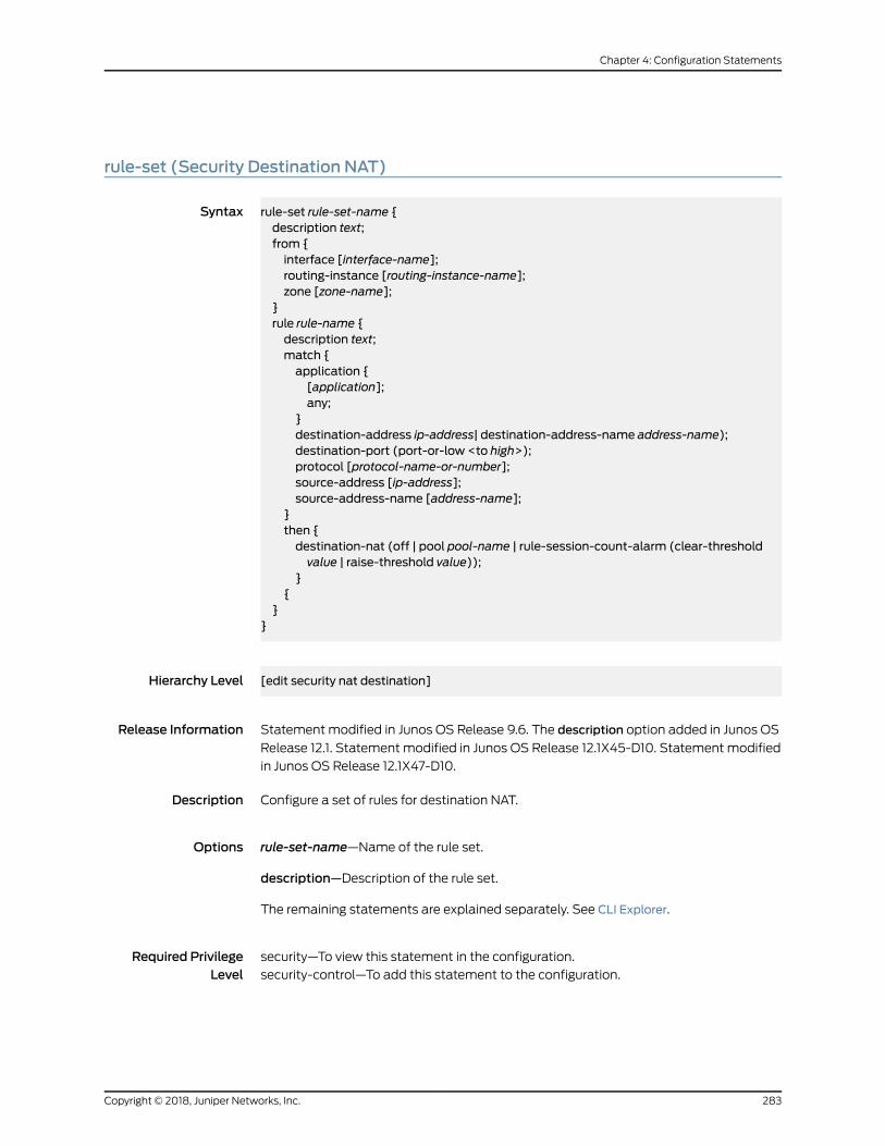
rule-set (Security Destination NAT)
Syntax rule-set rule-set-name {description text;from {interface [interface-name];routing-instance [routing-instance-name];zone [zone-name];
}rule rule-name {description text;match {application {[application];any;
}destination-address ip-address| destination-address-name address-name);destination-port (port-or-low <to high>);protocol [protocol-name-or-number];source-address [ip-address];source-address-name [address-name];
}then {destination-nat (off | pool pool-name | rule-session-count-alarm (clear-thresholdvalue | raise-threshold value));
}{
}}
Hierarchy Level [edit security nat destination]
Release Information Statement modified in Junos OS Release 9.6. The description option added in Junos OS
Release 12.1. Statement modified in Junos OS Release 12.1X45-D10. Statement modified
in Junos OS Release 12.1X47-D10.
Description Configure a set of rules for destination NAT.
Options rule-set-name—Name of the rule set.
description—Description of the rule set.
The remaining statements are explained separately. See CLI Explorer.
Required PrivilegeLevel
security—To view this statement in the configuration.
security-control—To add this statement to the configuration.
283Copyright © 2018, Juniper Networks, Inc.
Chapter 4: Configuration Statements

RelatedDocumentation
Copyright © 2018, Juniper Networks, Inc.284
Network Address Translation Feature Guide for Security Devices

rule-set (Security Source NAT)
Syntax rule-set rule-set-name {description text;from {interface [interface-name];routing-instance [routing-instance-name];zone [zone-name];
}rule rule-name {description text;match {application {[application];any;
}(destination-address <ip-address> | destination-address-name <address-name>);destination-port (port-or-low <to high>);protocol [protocol-name-or-number];source-address [ip-address];source-address-name [address-name];source-port (port-or-low <to high>);
}then {source-nat {interface {persistent-nat {address-mapping;inactivity-timeout seconds;max-session-number value;permit (any-remote-host | target-host | target-host-port);
}}off;pool <pool-name>persistent-nat {address-mapping;inactivity-timeout seconds;max-session-number number;permit (any-remote-host | target-host | target-host-port);
}}rule-session-count-alarm (raise-threshold value | clear-threshold value);
}}
}to {interface [interface-name];routing-instance [routing-instance-name];zone [zone-name];
}}
285Copyright © 2018, Juniper Networks, Inc.
Chapter 4: Configuration Statements

Hierarchy Level [edit security nat source]
Release Information Statement modified in Junos OS Release 9.6. The description option added in Junos OS
Release 12.1. Statement modified in Junos OS Release 12.1X45-D10. Statement modified
in Junos OS Release 12.1X47-D10.
Description Configure a set of rules for source NAT.
NOTE: Whenzonesarenotconfiguredunder rule-setandwhenactivesourceNAT is configured withmissingmandatory statement “from” then, thefollowingmessage isdisplayedwhenperformingcommit “Missingmandatory
statement: 'from' error: configuration check-out failed” and the configuration
check-out fails.
Options rule-set-name—Name of the rule set.
description—Description of the rule set.
The remaining statements are explained separately. See CLI Explorer.
Required PrivilegeLevel
security—To view this statement in the configuration.
security-control—To add this statement to the configuration.
RelatedDocumentation
Copyright © 2018, Juniper Networks, Inc.286
Network Address Translation Feature Guide for Security Devices

rule-set (Security Static NAT)
Syntax rule-set rule-set-name {description text;from {interface [interface-name];routing-instance [routing-instance-name];zone [zone-name];
}rule rule-name {description text;match {(destination-address ip-address | destination-address-name address-name);destination-port (port | low to high);source-address ip-address;source-address-name address-name;source-port (port or low <to high>);
}then {static-nat {inet {routing-instance (default | routing-instance-name);
}prefix {address-prefix;mapped-port lower-port-range to upper-port-range;routing-instance (default | routing-instance-name);
}prefix-name {address-prefix-name;mapped-port lower-port-range to upper-port-range;routing-instance (default | routing-instance-name);}
rule-session-count-alarm (raise-threshold value | clear-threshold value);}
}}
}
Hierarchy Level [edit security nat static]
Release Information Statement modified in Junos OS Release 9.6. The description option added in Junos OS
Release 12.1. The rule-session-count-alarm, source-address, source-address-name, and
source-port options added in Junos OS Release 12.1X45-D10.
Description Configure a set of rules for static NAT.
Options rule-set-name—Name of the rule set.
description—Description of the rule set.
287Copyright © 2018, Juniper Networks, Inc.
Chapter 4: Configuration Statements

The remaining statements are explained separately. See CLI Explorer.
Required PrivilegeLevel
security—To view this statement in the configuration.
security-control—To add this statement to the configuration.
RelatedDocumentation
Copyright © 2018, Juniper Networks, Inc.288
Network Address Translation Feature Guide for Security Devices

source (Security Source NAT)
Syntax source {address-persistent;interface (port-overloading off | port-overloading-factor number);pool pool-name {address ip-address {to ip-address;
}address-persistent subscriber ipv6-prefix-length prefix-length;address-pooling (paired | no-paired);address-shared;description text;host-address-base ip-address;overflow-pool (interface | pool-name);pool-utilization-alarm (clear-threshold value | raise-threshold value);port {block-allocation {active-block-timeout timeout-interval;block-size block-size;interim-logging-interval timeout-interval;last-block-recycle-timeout timeout-interval;log disable;maximum-blocks-per-hostmaximum-block-number
}deterministic {block-size block-size;host {address ip-address;address-name address-name;
}no-translation;port-overloading-factor number;range {port-low <to port-high>;to port-high;twin-port port-low <to port-high>;
}}routing-instance routing-instance-name;
}pool-default-port-range lower-port-range to upper-port-range;pool-default-twin-port-range lower-port-range to upper-port-range;pool-utilization-alarm (clear-threshold value | raise-threshold value);port-randomization disable;port-round-robin disable;port-scaling-enlargement;rule-set rule-set-name {description text;from {interface [interface-name];routing-instance [routing-instance-name];zone [zone-name];
289Copyright © 2018, Juniper Networks, Inc.
Chapter 4: Configuration Statements
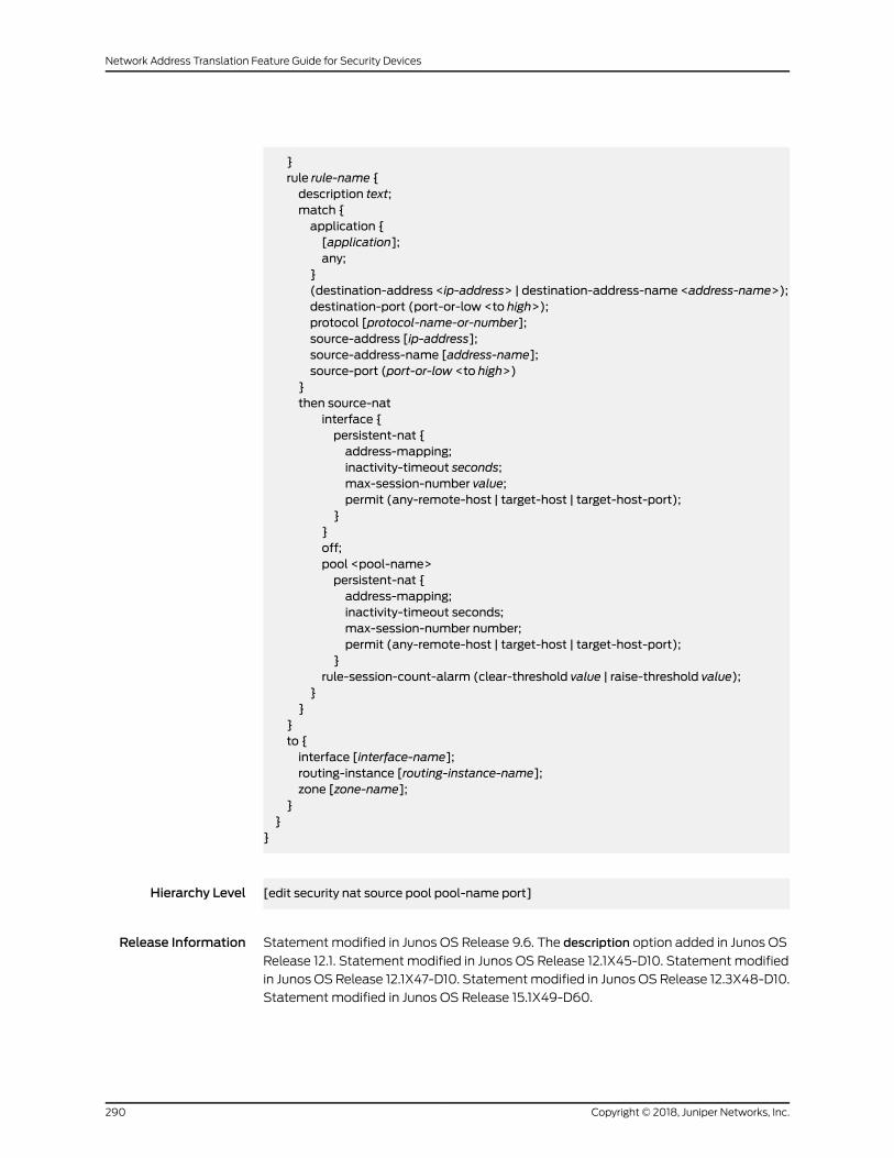
}rule rule-name {description text;match {application {[application];any;
}(destination-address <ip-address> | destination-address-name <address-name>);destination-port (port-or-low <to high>);protocol [protocol-name-or-number];source-address [ip-address];source-address-name [address-name];source-port (port-or-low <to high>)
}then source-nat
interface {persistent-nat {address-mapping;inactivity-timeout seconds;max-session-number value;permit (any-remote-host | target-host | target-host-port);
}}off;pool <pool-name>persistent-nat {address-mapping;inactivity-timeout seconds;max-session-number number;permit (any-remote-host | target-host | target-host-port);
}rule-session-count-alarm (clear-threshold value | raise-threshold value);
}}
}to {interface [interface-name];routing-instance [routing-instance-name];zone [zone-name];
}}
}
Hierarchy Level [edit security nat source pool pool-name port]
Release Information Statement modified in Junos OS Release 9.6. The description option added in Junos OS
Release 12.1. Statement modified in Junos OS Release 12.1X45-D10. Statement modified
in Junos OS Release 12.1X47-D10. Statementmodified in Junos OS Release 12.3X48-D10.
Statement modified in Junos OS Release 15.1X49-D60.
Copyright © 2018, Juniper Networks, Inc.290
Network Address Translation Feature Guide for Security Devices

Description Configure source NAT, which allows you to configure the following:
• Translate source IP address or addresses to the egress interface's IP address.
• Translatea rangeof source IPaddresses toanother rangeof IPaddresses. Thismapping
is dynamic and without PAT.
• Translatea rangeof source IPaddresses toanother rangeof IPaddresses. Thismapping
is dynamic and with PAT.
• Translatea rangeof source IPaddresses toanother rangeof IPaddresses. Thismapping
is one-to-one, static, and without PAT.
Options The remaining statements are explained separately. See CLI Explorer.
Required PrivilegeLevel
security—To view this statement in the configuration.
security-control—To add this statement to the configuration.
session-drop-hold-down
Syntax session-drop-hold-down time;
Hierarchy Level [edit security nat source]
Release Information Statement introduced in Junos OS Release 18.3R1.
Description Specify the session hold time value to hold the NAT source sessionwithout expiring. The
session hold time value must be 30 seconds through 28,800 seconds (eight hours).
Required PrivilegeLevel
services—To view this statement in the configuration.
services-control—To add this statement to the configuration.
291Copyright © 2018, Juniper Networks, Inc.
Chapter 4: Configuration Statements

session-persistence-scan
Syntax session-persistence-scan;
Hierarchy Level [edit security nat source]
Release Information Statement introduced in Junos OS Release 18.3R1.
Description Specify the sessions to be retained if there is a change in NAT configuration. The existing
sessions are retained, if the new session and existing sessions are in the same security
zone.
Required PrivilegeLevel
services—To view this statement in the configuration.
services-control—To add this statement to the configuration.
source-address (Security Destination NAT)
Syntax source-address [ip-address];
Hierarchy Level [edit security nat destination rule-set rule-set-name rule rule-namematch]
Release Information Statement modified in Junos OS Release 9.6.
Description Specify source address to match the rule. You can configure multiple addresses or
subnets.
Options ip-address—Source address or a subnet.
Required PrivilegeLevel
security—To view this statement in the configuration.
security-control—To add this statement to the configuration.
Copyright © 2018, Juniper Networks, Inc.292
Network Address Translation Feature Guide for Security Devices
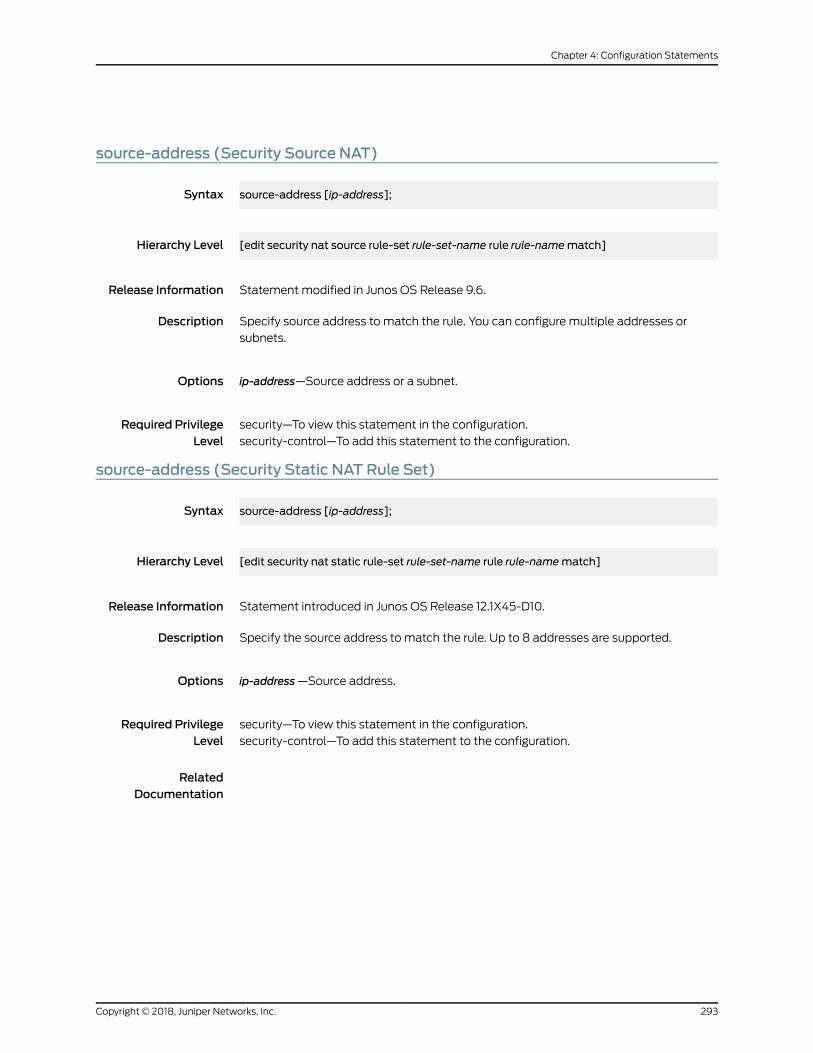
source-address (Security Source NAT)
Syntax source-address [ip-address];
Hierarchy Level [edit security nat source rule-set rule-set-name rule rule-namematch]
Release Information Statement modified in Junos OS Release 9.6.
Description Specify source address to match the rule. You can configure multiple addresses or
subnets.
Options ip-address—Source address or a subnet.
Required PrivilegeLevel
security—To view this statement in the configuration.
security-control—To add this statement to the configuration.
source-address (Security Static NAT Rule Set)
Syntax source-address [ip-address];
Hierarchy Level [edit security nat static rule-set rule-set-name rule rule-namematch]
Release Information Statement introduced in Junos OS Release 12.1X45-D10.
Description Specify the source address to match the rule. Up to 8 addresses are supported.
Options ip-address—Source address.
Required PrivilegeLevel
security—To view this statement in the configuration.
security-control—To add this statement to the configuration.
RelatedDocumentation
293Copyright © 2018, Juniper Networks, Inc.
Chapter 4: Configuration Statements
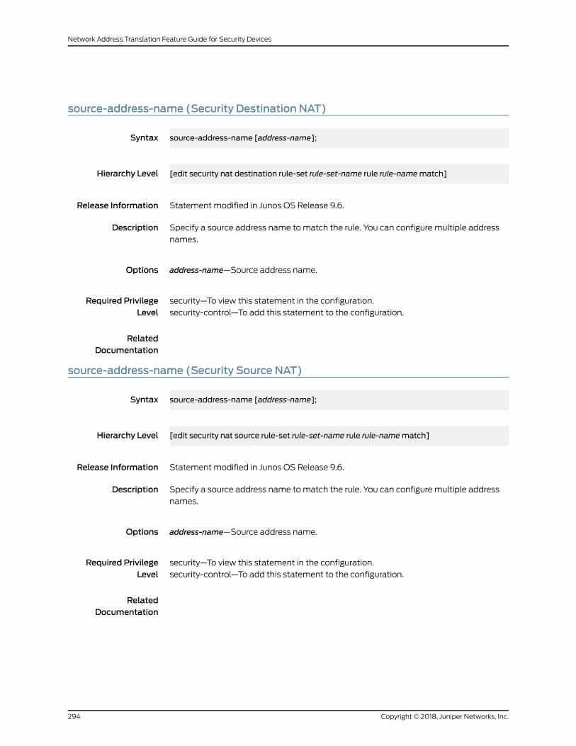
source-address-name (Security Destination NAT)
Syntax source-address-name [address-name];
Hierarchy Level [edit security nat destination rule-set rule-set-name rule rule-namematch]
Release Information Statement modified in Junos OS Release 9.6.
Description Specify a source address name tomatch the rule. You can configure multiple address
names.
Options address-name—Source address name.
Required PrivilegeLevel
security—To view this statement in the configuration.
security-control—To add this statement to the configuration.
RelatedDocumentation
source-address-name (Security Source NAT)
Syntax source-address-name [address-name];
Hierarchy Level [edit security nat source rule-set rule-set-name rule rule-namematch]
Release Information Statement modified in Junos OS Release 9.6.
Description Specify a source address name tomatch the rule. You can configure multiple address
names.
Options address-name—Source address name.
Required PrivilegeLevel
security—To view this statement in the configuration.
security-control—To add this statement to the configuration.
RelatedDocumentation
Copyright © 2018, Juniper Networks, Inc.294
Network Address Translation Feature Guide for Security Devices

source-address-name (Security Static NAT Rule Set)
Syntax source-address-name [address-name];
Hierarchy Level [edit security nat static rule-set rule-set-name rule rule-namematch]
Release Information Statement introduced in Junos OS Release 12.1X45-D10.
Description Specify a source address name tomatch the rule. Up to 8 address names are supported.
Options address-name—Source address name.
Required PrivilegeLevel
security—To view this statement in the configuration.
security-control—To add this statement to the configuration.
RelatedDocumentation
295Copyright © 2018, Juniper Networks, Inc.
Chapter 4: Configuration Statements

source-nat
Syntax source-nat {interface {persistent-nat {address-mapping;inactivity-timeout seconds;max-session-number value;permit (any-remote-host | target-host | target-host-port);
}}off;pool <pool-name>;persistent-nat {address-mapping;inactivity-timeout seconds;max-session-number number;permit (any-remote-host | target-host | target-host-port);
}rule-session-count-alarm (clear-threshold value | raise-threshold value);
}
Hierarchy Level [edit security nat source rule-set rule-set-name rule rule-name then]
Release Information Statement modified in Junos OS Release 9.6. Statement modified in Junos OS Release
12.1X45-D10.
Description Specify the action of the source NAT rule.
Options • off—Do not perform the source NAT operation.
The remaining statements are explained separately. See CLI Explorer.
Required PrivilegeLevel
security — To view this statement in the configuration.
security-control— To add this statement to the configuration.
Copyright © 2018, Juniper Networks, Inc.296
Network Address Translation Feature Guide for Security Devices
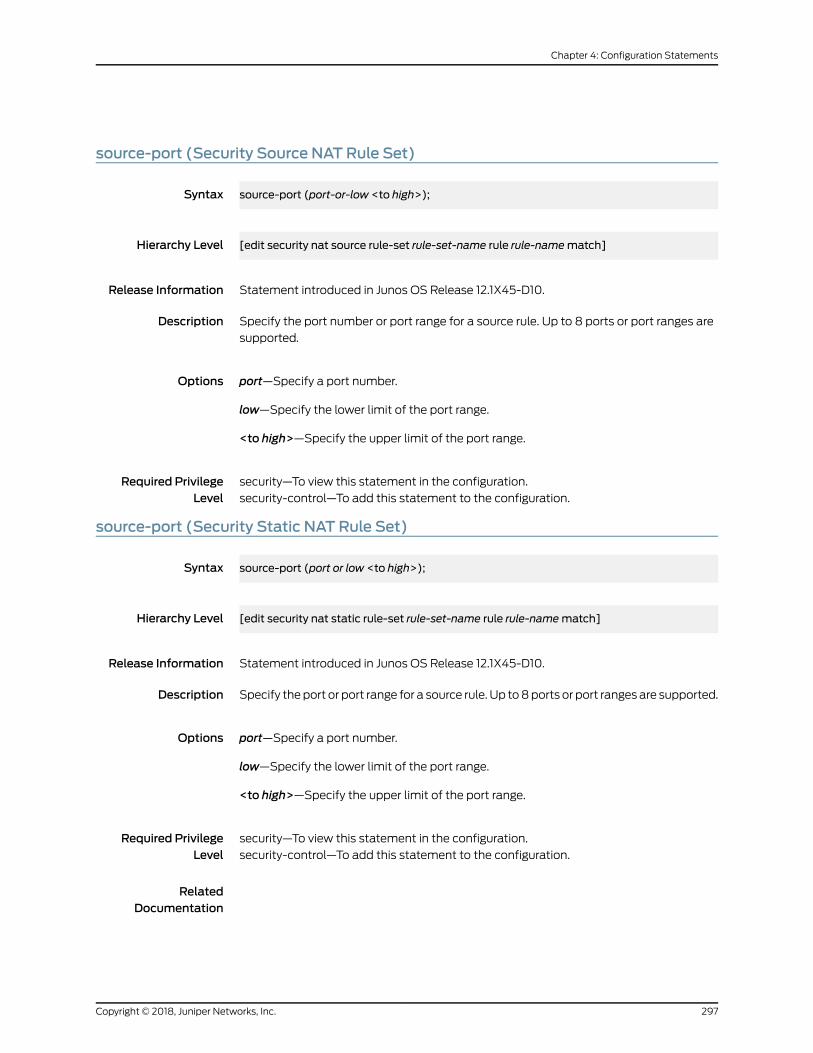
source-port (Security Source NAT Rule Set)
Syntax source-port (port-or-low <to high>);
Hierarchy Level [edit security nat source rule-set rule-set-name rule rule-namematch]
Release Information Statement introduced in Junos OS Release 12.1X45-D10.
Description Specify the port number or port range for a source rule. Up to 8 ports or port ranges are
supported.
Options port—Specify a port number.
low—Specify the lower limit of the port range.
<to high>—Specify the upper limit of the port range.
Required PrivilegeLevel
security—To view this statement in the configuration.
security-control—To add this statement to the configuration.
source-port (Security Static NAT Rule Set)
Syntax source-port (port or low <to high>);
Hierarchy Level [edit security nat static rule-set rule-set-name rule rule-namematch]
Release Information Statement introduced in Junos OS Release 12.1X45-D10.
Description Specify theport or port range for a source rule. Up to8ports or port ranges are supported.
Options port—Specify a port number.
low—Specify the lower limit of the port range.
<to high>—Specify the upper limit of the port range.
Required PrivilegeLevel
security—To view this statement in the configuration.
security-control—To add this statement to the configuration.
RelatedDocumentation
297Copyright © 2018, Juniper Networks, Inc.
Chapter 4: Configuration Statements

static (Security NAT)
Syntax static {rule-set rule-set-name {description text;from {interface [interface-name];routing-instance [routing-instance-name];zone [zone-name];
}rule rule-name {description text;match {(destination-address <ip-address> | destination-address-name <address-name>);destination-port (port-or-low | <to high>);source-address [ip-address];source-address-name [ip-address-name];source-port (port-or-low <to high>);
}then {static-nat {inet {routing-instance (routing-instance-name| default);
}nptv6-prefix {address-prefix;routing-instance routing-instance-name;
nptv6-prefix-name {address-prefix-name;routing-instance routing-instance-name;
[prefix {address-prefix;mapped-port lower-port-range to upper-port-range;
routing-instance (routing-instance-name| default);}prefix {address-prefix-name;mapped-port lower-port-range to upper-port-range;routing-instance (routing-instance-name| default);
}rule-session-count-alarm (clear-threshold value | raise-threshold value);
}}
}}
}
Hierarchy Level [edit security nat]
Copyright © 2018, Juniper Networks, Inc.298
Network Address Translation Feature Guide for Security Devices
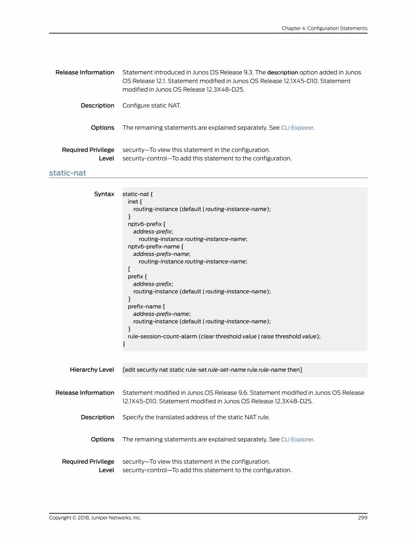
Release Information Statement introduced in Junos OS Release 9.3. The description option added in Junos
OS Release 12.1. Statement modified in Junos OS Release 12.1X45-D10. Statement
modified in Junos OS Release 12.3X48-D25.
Description Configure static NAT.
Options The remaining statements are explained separately. See CLI Explorer.
Required PrivilegeLevel
security—To view this statement in the configuration.
security-control—To add this statement to the configuration.
static-nat
Syntax static-nat {inet {routing-instance (default | routing-instance-name);
}nptv6-prefix {address-prefix;routing-instance routing-instance-name;
nptv6-prefix-name {address-prefix-name;routing-instance routing-instance-name;
[prefix {address-prefix;routing-instance (default | routing-instance-name);
}prefix-name {address-prefix-name;routing-instance (default | routing-instance-name);
}rule-session-count-alarm (clear threshold value | raise threshold value);
}
Hierarchy Level [edit security nat static rule-set rule-set-name rule rule-name then]
Release Information Statement modified in Junos OS Release 9.6. Statement modified in Junos OS Release
12.1X45-D10. Statement modified in Junos OS Release 12.3X48-D25.
Description Specify the translated address of the static NAT rule.
Options The remaining statements are explained separately. See CLI Explorer.
Required PrivilegeLevel
security—To view this statement in the configuration.
security-control—To add this statement to the configuration.
299Copyright © 2018, Juniper Networks, Inc.
Chapter 4: Configuration Statements

to (Security Source NAT)
Syntax to {interface [interface-name];routing-instance [routing-instance-name];zone [zone-name];
}
Hierarchy Level [edit security nat source rule-set rule-set-name]
Release Information Statement introduced in Junos OS Release 9.2.
Description Specify the destination of the packet among the routing instance, interface, or zone.
Options • interface [interface-name]—Name of the interface.
• routing-instance [routing-instance-name]—Name of the routing instance.
• zone [zone-name]—Name of the zone.
Required PrivilegeLevel
security—To view this statement in the configuration.
security-control—To add this statement to the configuration.
RelatedDocumentation
Copyright © 2018, Juniper Networks, Inc.300
Network Address Translation Feature Guide for Security Devices

then (Security Destination NAT)
Syntax then {destination-nat (off | pool pool-name | rule-session-count-alarm (clear-threshold value |raise-threshold value));
}
Hierarchy Level [edit security nat destination rule-set rule-set-name rule rule-name]
Release Information Statement modified in Junos OS Release 9.6. Statement modified in Junos OS Release
12.1X45-D10.
Description Specify theaction tobeperformedwhen trafficmatches thedestinationNAT rulecriteria.
Options The remaining statements are explained separately. See CLI Explorer.
Required PrivilegeLevel
security—To view this statement in the configuration.
security-control—To add this statement to the configuration.
301Copyright © 2018, Juniper Networks, Inc.
Chapter 4: Configuration Statements
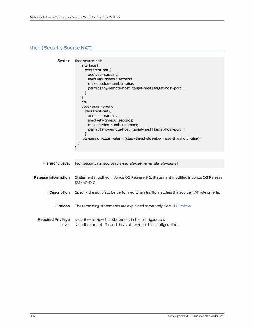
then (Security Source NAT)
Syntax then source-nat;interface {persistent-nat {address-mapping;inactivity-timeout seconds;max-session-number value;permit (any-remote-host | target-host | target-host-port);
}}off;pool <pool-name>;persistent-nat {address-mapping;inactivity-timeout seconds;max-session-number number;permit (any-remote-host | target-host | target-host-port);
}rule-session-count-alarm (clear-threshold value | raise-threshold value);
}}
Hierarchy Level [edit security nat source rule-set rule-set-name rule rule-name]
Release Information Statement modified in Junos OS Release 9.6. Statement modified in Junos OS Release
12.1X45-D10.
Description Specify the action to be performed when traffic matches the source NAT rule criteria.
Options The remaining statements are explained separately. See CLI Explorer.
Required PrivilegeLevel
security—To view this statement in the configuration.
security-control—To add this statement to the configuration.
Copyright © 2018, Juniper Networks, Inc.302
Network Address Translation Feature Guide for Security Devices

then (Security Static NAT)
Syntax then {static-nat {inet {routing-instance (default | routing-instance-name);
}nptv6-prefix {address-prefix;routing-instance routing-instance-name;
nptv6-prefix-name {address-prefix-name;routing-instance routing-instance-name;
[prefix {address-prefix;mapped-port lower-port-range to upper-port-range;routing-instance (default | routing-instance-name);
}prefix-name {address-prefix-name;mapped-port lower-port-range to upper-port-range;routing-instance (default | routing-instance-name);
}rule-session-count-alarm (clear-threshold value | raise-threshold value);
}
Hierarchy Level [edit security nat static rule-set rule-set-name rule rule-name]
Release Information Statement modified in Junos OS Release 9.6. Statement modified in Junos OS Release
12.1X45-D10. Statement modified in Junos OS Release 12.3X48-D25.
Description Specify the action to be performed when traffic matches the static NAT rule criteria.
Options The remaining statements are explained separately. See CLI Explorer.
Required PrivilegeLevel
security—To view this statement in the configuration.
security-control—To add this statement to the configuration.
RelatedDocumentation
303Copyright © 2018, Juniper Networks, Inc.
Chapter 4: Configuration Statements

traceoptions (Security NAT)
Syntax traceoptions {file {filename;files number;match regular-expression;sizemaximum-file-size;(world-readable | no-world-readable);
}flag flag;no-remote-trace;
}
Hierarchy Level [edit security nat]
Release Information Statement modified in Junos OS Release 9.6.
Description Configure NAT tracing options.
Options file—Configure the trace file options.•
• filename—Name of the file to receive the output of the tracing operation. Enclose
the namewithin quotation marks. All files are placed in the directory /var/log. By
default, the name of the file is the name of the process being traced.
• files number—Maximum number of trace files. When a trace file named trace-file
reaches its maximum size, it is renamed to trace-file.0, then trace-file.1, and so on,
until the maximum number of trace files is reached. The oldest archived file is
overwritten.
If you specify amaximumnumber of files, you alsomust specify amaximum file size
with the size option and a filename.
Range: 2 through 1000 files
Default: 10 files
• match regular-expression—Refine the output to include lines that contain the regular
expression.
• sizemaximum-file-size—Maximumsizeof each trace file, in kilobytes (KB),megabytes
(MB), or gigabytes (GB). When a trace file named trace-file reaches this size, it is
renamed trace-file.0.When the trace-fileagain reaches itsmaximumsize, trace-file.0
is renamed trace-file.1 and trace-file is renamed trace-file.0. This renaming scheme
continues until themaximumnumber of trace files is reached. Then the oldest trace
file is overwritten.
If youspecify amaximumfile size, youalsomust specify amaximumnumberof trace
files with the files option and a filename.
Copyright © 2018, Juniper Networks, Inc.304
Network Address Translation Feature Guide for Security Devices
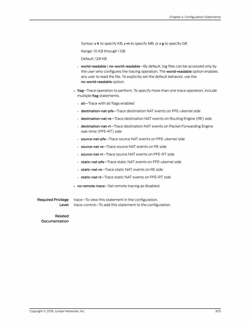
Syntax: x K to specify KB, xm to specify MB, or x g to specify GB
Range: 10 KB through 1 GB
Default: 128 KB
• world-readable | no-world-readable—By default, log files can be accessed only by
the user who configures the tracing operation. Theworld-readable option enables
any user to read the file. To explicitly set the default behavior, use the
no-world-readable option.
• flag—Trace operation to perform. To specify more than one trace operation, include
multiple flag statements.
• all—Trace with all flags enabled
• destination-nat-pfe—Trace destination NAT events on PFE-ukernel side
• destination-nat-re—Trace destination NAT events on Routing Engine (RE) side
• destination-nat-rt—Trace destination NAT events on Packet Forwarding Engine
real-time (PFE-RT) side
• source-nat-pfe—Trace source NAT events on PFE-ukernel side
• source-nat-re—Trace source NAT events on RE side
• source-nat-rt—Trace source NAT events on PFE-RT side
• static-nat-pfe—Trace static NAT events on PFE-ukernel side
• static-nat-re—Trace static NAT events on RE side
• static-nat-rt—Trace static NAT events on PFE-RT side
• no-remote-trace—Set remote tracing as disabled.
Required PrivilegeLevel
trace—To view this statement in the configuration.
trace-control—To add this statement to the configuration.
RelatedDocumentation
305Copyright © 2018, Juniper Networks, Inc.
Chapter 4: Configuration Statements

Copyright © 2018, Juniper Networks, Inc.306
Network Address Translation Feature Guide for Security Devices

CHAPTER 5
Operational Commands
• clear security nat incoming-table
• clear security nat source persistent-nat-table
• clear security nat statistics destination pool
• clear security nat statistics destination rule
• clear security nat statistics source pool
• clear security nat statistics source rule
• clear security nat statistics static rule
• show security nat destination pool
• show security nat destination rule
• show security nat destination rule-application
• show security nat destination summary
• show security nat incoming-table
• show security nat interface-nat-ports
• show security nat resource-usage source-pool
• show security nat source deterministic
• show security nat source paired-address
• show security nat source persistent-nat-table
• show security nat source pool
• show security nat source port-block
• show security nat source rule
• show security nat source rule-application
• show security nat source summary
• show security nat static rule
307Copyright © 2018, Juniper Networks, Inc.
clear security nat incoming-table
Syntax clear security nat incoming-table<node ( node-id | all | local | primary)>
Release Information Command introduced in Junos OS Release 8.5. The node options added in Junos OS
Release 9.0.
Description Clear Network Address Translation (NAT) incoming table information.
Options none—Clear all information NAT incoming table.•
• node—(Optional) For chassis cluster configurations, clear incoming table information
on a specific node (device) in the cluster.
• node-id—Identification number of the node. It can be 0 or 1.
• all—Clear all nodes.
• local—Clear the local node.
• primary—Clear the primary node.
Required PrivilegeLevel
clear
RelatedDocumentation
show security nat incoming-table on page 327•
Output Fields This command produces no output.
Copyright © 2018, Juniper Networks, Inc.308
Network Address Translation Feature Guide for Security Devices

clear security nat source persistent-nat-table
Syntax clear security nat source persistent-nat-table( all | interface | internal-ip ip-address <internal-port port> | pool poolname )
Release Information Command introduced in Junos OS Release 10.0.
Description Clear Network Address Translation (NAT) persistent NAT bindings that are in query
mode, where all sessions of the binding are gone.
Options • all—Clear all persistent NAT bindings that are in query mode.
• interface—Clear persistent NAT bindings that are in query mode for the specified
interface.
• internal-ip ip-address—ClearpersistentNATbindings for thespecified internal IPaddress.
• internal-ip ip-address internal-portport—Clear persistentNATbindings that are in query
mode for the specified internal IP address and port.
• pool—Clear persistent NAT bindings that are in query mode for the specified source
NAT pool.
Required PrivilegeLevel
clear
RelatedDocumentation
show security nat source persistent-nat-table on page 340•
Output Fields This command produces no output.
309Copyright © 2018, Juniper Networks, Inc.
Chapter 5: Operational Commands
clear security nat statistics destination pool
Syntax clear security nat statistics destination pool<pool-name>all
Release Information Command introduced in Junos OS Release 11.1.
Description Clear the destination NAT pool information.
Options pool-name—Clear specified destination nat pool information.
all—Clear all destination nat pool information.
Required PrivilegeLevel
clear
RelatedDocumentation
show security nat destination pool on page 315•
• show security nat destination summary on page 324
Output Fields When you enter this command, you are provided feedback on the status of your request.
Copyright © 2018, Juniper Networks, Inc.310
Network Address Translation Feature Guide for Security Devices
clear security nat statistics destination rule
Syntax clear security nat statistics destination rule<rule-name>alll
Release Information Command introduced in Junos OS Release 11.1.
Description Clear the destination NAT rule information.
Options rule-name—Clear specified destination nat rule-set information.
all—Clear all destination nat rule-set information.
Required PrivilegeLevel
clear
RelatedDocumentation
show security nat destination rule on page 318•
• show security nat destination summary on page 324
Output Fields When you enter this command, you are provided feedback on the status of your request.
311Copyright © 2018, Juniper Networks, Inc.
Chapter 5: Operational Commands

clear security nat statistics source pool
Syntax clear security nat statistics source pool<pool-name>all
Release Information Command introduced in Junos OS Release 11.1.
Description Clear the source NAT statistic pool information.
Options pool-name—Clear the specified source nat pool information.
all—Clear all source pool information.
Required PrivilegeLevel
clear
RelatedDocumentation
show security nat source pool on page 343•
• show security nat source summary on page 358
Output Fields When you enter this command, you are provided feedback on the status of your request.
Copyright © 2018, Juniper Networks, Inc.312
Network Address Translation Feature Guide for Security Devices

clear security nat statistics source rule
Syntax clear security nat statistics source rule<rule-name>all
Release Information Command introduced in Junos OS Release 11.1.
Description Clear the source NAT statistic rule-set information.
Options rule-name—Clear the specified source rule-set information.
all—Clear all source nat rule-set information.
Required PrivilegeLevel
clear
RelatedDocumentation
show security nat source summary on page 358•
• show security nat source rule on page 352
Output Fields When you enter this command, you are provided feedback on the status of your request.
313Copyright © 2018, Juniper Networks, Inc.
Chapter 5: Operational Commands

clear security nat statistics static rule
Syntax clear security nat statistics static rule<rule-name>all
Release Information Command introduced in Junos OS Release 11.1.
Description Clear the static NAT rule-set information.
Options rule-name—Clear specified static nat rule-set information.
all—Clear all static nat rule-set information.
Required PrivilegeLevel
clear
RelatedDocumentation
show security nat static rule on page 361•
Output Fields When you enter this command, you are provided feedback on the status of your request.
Copyright © 2018, Juniper Networks, Inc.314
Network Address Translation Feature Guide for Security Devices

show security nat destination pool
Syntax show security nat destination poolpool-namealllogical-system (logical-system-name )root-logical-systemtenant (tenant-name )
Release Information Command introduced in Junos OS Release 9.2.
The Description output field added in Junos OS Release 12.1.
Support for IPv6 logical systems added in Junos OS Release 12.1X45-D10.
The tenant option is introduced in Junos OS Release 18.3R1.
Description Display information about the specified Network Address Translation (NAT) destination
address pool.
Options pool-name—Name of the destination address pool.
all—Display information about all the destination NAT address pools.
logical-system(logical-system-name)—Display information about the destinationNATpools for a specified logical system. Specify all to display information for all logical
systems.
root-logical-system—Display informationabout thedestinationNATpools for themaster(root) logical system.
tenant (tenant-name)—Display information about the destination NAT pools for aspecified tenant system. Specify all to display information for all tenant systems.
Required PrivilegeLevel
view
RelatedDocumentation
pool (Security Destination NAT) on page 257•
List of Sample Output show security nat destination pool dst-nat-pool1 on page 316show security nat destination pool all on page 316show security nat destination pool all tenant on page 317
Output Fields Table 15 on page 316 lists the output fields for the show security nat destination pool
command. Output fields are listed in the approximate order in which they appear.
315Copyright © 2018, Juniper Networks, Inc.
Chapter 5: Operational Commands

Table 15: show security nat destination pool Output Fields
Field DescriptionField Name
Name of the destination pool.Pool name
Description of the destination pool.Description
Pool identification number.Pool id
Name of the routing instance.Routing instance
Number of IP addresses that are in use.Total address
Number of translation hits.Translation hits
IP address or IP address range for the pool.Address range
Sample Output
show security nat destination pool dst-nat-pool1
user@host> show security nat destination pool dst-p1
Pool name : dst-p1Description : The destination pool dst-p1 is for the sales teamPool id : 1Routing instance: defaultTotal address : 1Translation hits: 0Address range Port 203.0.113.1 -203.0.113.1 0
Sample Output
show security nat destination pool all
user@host> show security nat destination pool all
Total destination-nat pools: 2
Pool name : dst-p1Description : The destination pool dst-p1 is for the sales teamPool id : 1Routing instance: defaultTotal address : 1Translation hits: 0Address range Port 203.0.113.1 -203.0.113.1 0
Pool name : dst-p2Description : The destination pool dst-p2 is for the sales teamPool id : 2Routing instance: default
Copyright © 2018, Juniper Networks, Inc.316
Network Address Translation Feature Guide for Security Devices

Total address : 1Translation hits: 0Address range Port 2001:db8::1 - 2001:db8::1 0
show security nat destination pool all tenant
user@host> show security nat destination pool all tenant tn1
Total destination-nat pools: 1Pool name : h1Pool id : 1Total address : 1Translation hits: 0Address range Port 192.168.1.200 - 192.168.1.200 0
317Copyright © 2018, Juniper Networks, Inc.
Chapter 5: Operational Commands
show security nat destination rule
Syntax show security nat destination rulerule-namealllogical-system (logical-system-name)root-logical-systemtenant (tenant-name)
Release Information Command introduced in Junos OS Release 9.2. The Description output field added in
Junos OS Release 12.1.
Support for IPv6 logical systemsand theSuccessfulsessions,FailedsessionsandNumber
of sessions output fields added in Junos OS Release 12.1X45-D10.
Output for multiple destination ports and the application option field added in Junos OS
Release 12.1X47-D10.
The tenant option is introduced in Junos OS Release 18.3R1.
Description Display information about the specified destination Network Address Translation (NAT)
rule. Destination NAT rules are processed after static NAT rules but before source NAT
rules.
Options rule-name—Display information about the specified destination NAT rule.
all—Display information about all the destination NAT rules.
logical-system—Display information about the destination NAT rules for a specified
logical system. Specify all to display information for all logical systems.
root-logical-system—Display informationabout thedestinationNAT rules for themaster(root) logical system.
tenant—Display information about the destination NAT rules for a specified tenantsystem. Specify all to display information for all tenant systems.
Required PrivilegeLevel
view
RelatedDocumentation
rule (Security Destination NAT) on page 276•
List of Sample Output show security nat destination rule dst2-rule on page 319show security nat destination rule all on page 320show security nat destination rule all tenant on page 320
Output Fields Table 16 on page 319 lists the output fields for the show security nat destination rule
command. Output fields are listed in the approximate order in which they appear.
Copyright © 2018, Juniper Networks, Inc.318
Network Address Translation Feature Guide for Security Devices

Table 16: show security nat destination rule Output Fields
Field DescriptionField Name
Number of destination NAT rules.Total destination-nat rules
Number of IP prefixes referenced in source, destination, and static NAT rules. This totalincludes the IP prefixes configured directly as address names and as address set namesin the rule.
Total referenced IPv4/IPv6ip-prefixes
Name of the destination NAT rule.Destination NAT rule
Description of the destination NAT rule.Description
Rule identification number.Rule-Id
Position of the destination NAT rule.Rule position
Name of the routing instance fromwhich the packets flow.From routing instance
Name of the interface fromwhich the packets flow.From interface
Name of the zone fromwhich the packets flow.From zone
Name of the source addresses that match the rule. The default value is any.Source addresses
Name of the destination addresses that match the rule. The default value is any.Destination addresses
The action takenwhen a packetmatches the rule’s tuples. Actions include the following:
• destination NAT pool—Use user-defined destination NAT pool to perform destinationNAT.
• off—Do not perform destination NAT.
Action
Destination ports number that match the rule. The default value is any.Destination ports
Indicates whether the application option is configured.Application
Number of translation hits.Translation hits
Number of successful session installations after the NAT rule is matched.Successful sessions
Number of unsuccessful session installations after the NAT rule is matched.Failed sessions
Number of sessions that reference the specified rule.Number of sessions
Sample Output
show security nat destination rule dst2-rule
user@host>show security nat destination rule dst2-rule
319Copyright © 2018, Juniper Networks, Inc.
Chapter 5: Operational Commands

Destination NAT rule: dst2-rule Rule-set: dst2 Description : The destination rule dst2-rule is for the sales team Rule-Id : 1 Rule position : 1 From routing instance : ri1 : ri2 Match Source addresses : add1 add2 Destination addresses : add9 Action : off
Destination port : 0 Translation hits : 68 Successful sessions : 25 Failed sessions : 43 Number of sessions : 2
Sample Output
show security nat destination rule all
user@host> show security nat destination rule all
Total destination-nat rules: 1Total referenced IPv4/IPv6 ip-prefixes: 2/0
Destination NAT rule: r4 Rule-set: rs4 Rule-Id : 2 Rule position : 2 From zone : untrust Match Source addresses : 192.0.2.0 - 192.0.2.255 Destination addresses : 198.51.100.0 - 198.51.100.255 Application : configured Action : off Translation hits : 0 Successful sessions : 0 Failed sessions : 0 Number of sessions : 0
show security nat destination rule all tenant
user@host> show security nat destination rule all tenant tn1
Total destination-nat rules: 1Total referenced IPv4/IPv6 ip-prefixes: 2/0Destination NAT rule: r1 Rule-set: from_zone Rule-Id : 1 Rule position : 1 From zone : untrust Match Source addresses : 192.0.2.0 - 192.0.2.255
Copyright © 2018, Juniper Networks, Inc.320
Network Address Translation Feature Guide for Security Devices

Destination addresses : 203.0.113.202 - 203.0.113.202 Action : h1 Translation hits : 0 Successful sessions : 0 Failed sessions : 0 Number of sessions : 0
321Copyright © 2018, Juniper Networks, Inc.
Chapter 5: Operational Commands

show security nat destination rule-application
Syntax show security nat destination rule-applicationrule-namealllogical-system logical-system-nameroot-logical-system
Release Information Command introduced in Junos OS Release 12.1X47-D10.
Description Display information about the specified destination Network Address Translation (NAT)
rule application.
Options rule-name—Display information about the specified destination NAT rule application.
all—Display information about all the destination NAT rule applications.
logical-system logical-system-name—Display information about the destination NATrule applications for the specified logical system.
root-logical-system—Display information about the destination NAT rule applicationsfor the master (root) logical system.
Required PrivilegeLevel
view
RelatedDocumentation
Logical Systems and Tenant Systems Feature Guide for Security Devices•
List of Sample Output show security nat destination rule-application for port application on page 323show security nat destination rule-application for ICMP application on page 323
Output Fields Table 17 on page 322 lists the output fields for the show security nat destination
rule-application command. Output fields are listed in the approximate order in which
they appear.
Table 17: show security nat destination rule-application Output Fields
Field DescriptionField Name
Name of the destination NAT rule.Destination NAT rule
Rule set identification number.Rule-set
Rule identification number.Rule-Id
Name of the application or application set.Application
Copyright © 2018, Juniper Networks, Inc.322
Network Address Translation Feature Guide for Security Devices
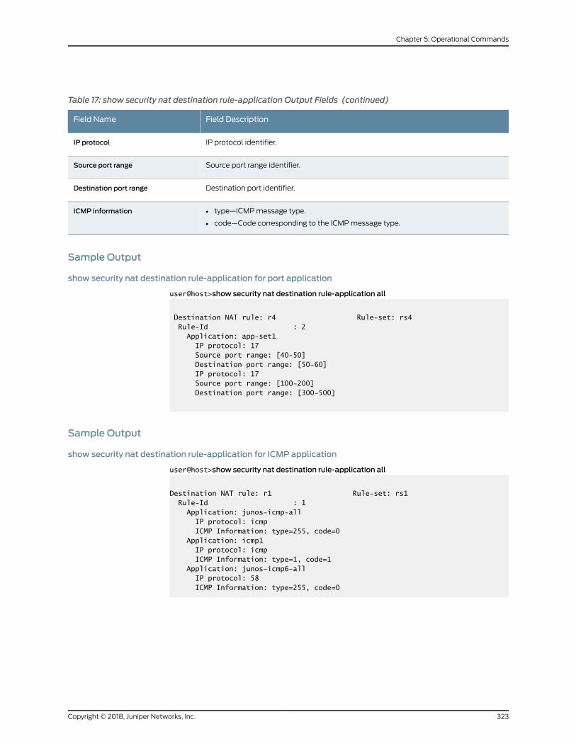
Table 17: show security nat destination rule-application Output Fields (continued)
Field DescriptionField Name
IP protocol identifier.IP protocol
Source port range identifier.Source port range
Destination port identifier.Destination port range
• type—ICMPmessage type.
• code—Code corresponding to the ICMPmessage type.
ICMP information
Sample Output
show security nat destination rule-application for port application
user@host>show security nat destination rule-application all
Destination NAT rule: r4 Rule-set: rs4 Rule-Id : 2 Application: app-set1 IP protocol: 17 Source port range: [40-50] Destination port range: [50-60] IP protocol: 17 Source port range: [100-200] Destination port range: [300-500]
Sample Output
show security nat destination rule-application for ICMP application
user@host>show security nat destination rule-application all
Destination NAT rule: r1 Rule-set: rs1 Rule-Id : 1 Application: junos-icmp-all IP protocol: icmp ICMP Information: type=255, code=0 Application: icmp1 IP protocol: icmp ICMP Information: type=1, code=1 Application: junos-icmp6-all IP protocol: 58 ICMP Information: type=255, code=0
323Copyright © 2018, Juniper Networks, Inc.
Chapter 5: Operational Commands

show security nat destination summary
Syntax show security nat destination summarylogical-system (logical-system-name )root-logical-systemtenant (tenant-name )
Release Information Command introduced in Junos OS Release 9.2.
Support for IPv6 logical systems added in Junos OS Release 12.1X45-D10.
The tenant option is introduced in Junos OS Release 18.3R1.
Description Display a summary of Network Address Translation (NAT) destination pool information.
Options none—Display summary information about the destination NAT pool.
logical-system—Display summary informationabout thedestinationNAT for a specified
logical system. Specify all to display information for all logical systems.
root-logical-system—Display summary information about the destination NAT for themaster (root) logical system.
tenant—Display information about the destination NAT for a specified tenant system.Specify all to display information for all tenant systems.
Required PrivilegeLevel
view
RelatedDocumentation
pool (Security Destination NAT) on page 257•
• rule (Security Destination NAT) on page 276
List of Sample Output show security nat destination summary on page 325show security nat destination summary tenant on page 325
Output Fields Table 18 on page 324 lists the output fields for the showsecurity nat destination summary
command. Output fields are listed in the approximate order in which they appear.
Table 18: show security nat destination summary Output Fields
Field DescriptionField Name
Number of destination NAT pools.Total destination nat pool number
Name of the destination address pool.Pool name
IP address or IP address range for the pool.Address range
Name of the routing instance.Routing Instance
Copyright © 2018, Juniper Networks, Inc.324
Network Address Translation Feature Guide for Security Devices

Table 18: show security nat destination summary Output Fields (continued)
Field DescriptionField Name
Port number.Port
Number of IP addresses that are in use.Total
Number of IP addresses that are free for use.Available
Number of destination NAT rules.Total destination nat rule number
Number of times a translation in the translation table is used for all the destination NATrules.
Total hit times
Number of times a translation in the translation table failed to translate for all thedestination NAT rules.
Total fail times
Sample Output
show security nat destination summary
user@host> show security nat destination summary
Total pools: 2Pool name Address Routing Port Total Range Instance Addressdst-p1 203.0.113.1 -203.0.113.1 default 0 1 dst-p2 2001:db8::1 - 2001:db8::1 default 0 1
Total rules: 171Rule name Rule set From Actiondst2-rule dst2 ri1 ri2 ri3 ri4 ri5 ri6 ri7 dst3-rule dst3 ri9 off ri1 ri2 ri3 ri4 ri5
...
show security nat destination summary tenant
user@host> show security nat destination summary tenant tn1
Total pools: 1Pool name Address Routing Port Total
325Copyright © 2018, Juniper Networks, Inc.
Chapter 5: Operational Commands

Range Instance Addressh1 192.168.1.200 - 192.168.1.200 0 1
Total rules: 1Rule name Rule set From Actionr1 from_zone untrust h1
Copyright © 2018, Juniper Networks, Inc.326
Network Address Translation Feature Guide for Security Devices
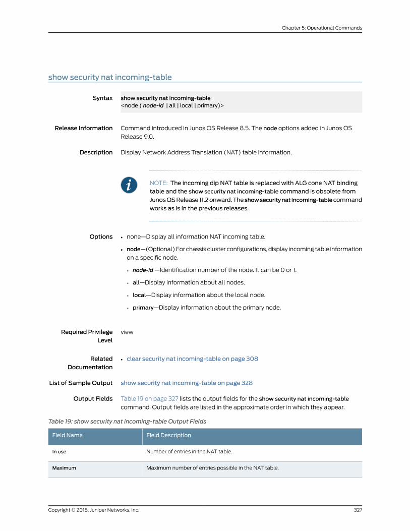
show security nat incoming-table
Syntax show security nat incoming-table<node ( node-id | all | local | primary)>
Release Information Command introduced in Junos OS Release 8.5. The node options added in Junos OS
Release 9.0.
Description Display Network Address Translation (NAT) table information.
NOTE: The incoming dip NAT table is replaced with ALG cone NAT bindingtable and the show security nat incoming-table command is obsolete from
JunosOSRelease 11.2onward.The showsecuritynat incoming-tablecommand
works as is in the previous releases.
Options none—Display all information NAT incoming table.•
• node—(Optional) For chassis cluster configurations, display incoming table information
on a specific node.
• node-id—Identification number of the node. It can be 0 or 1.
• all—Display information about all nodes.
• local—Display information about the local node.
• primary—Display information about the primary node.
Required PrivilegeLevel
view
RelatedDocumentation
clear security nat incoming-table on page 308•
List of Sample Output show security nat incoming-table on page 328
Output Fields Table 19 on page 327 lists the output fields for the show security nat incoming-table
command. Output fields are listed in the approximate order in which they appear.
Table 19: show security nat incoming-table Output Fields
Field DescriptionField Name
Number of entries in the NAT table.In use
Maximum number of entries possible in the NAT table.Maximum
327Copyright © 2018, Juniper Networks, Inc.
Chapter 5: Operational Commands

Table 19: show security nat incoming-table Output Fields (continued)
Field DescriptionField Name
Number of entries failed for allocation.Entry allocation failed
Destination IP address and port number.Destination
Host IP address and port number that the destination IP address is mapped.Host
Number of sessions referencing the entry.References
Timeout, in seconds, of the entry in the NAT table.Timeout
Name of source pool where translation is allocated.Source-pool
Sample Output
show security nat incoming-table
user@host> show security nat incoming-table
In use: 1, Maximum: 1024, Entry allocation failed: 0Destination Host References Timeout Source-pool10.1.1.26:1028 203.0.113.10:5060 1 3600 p1
Copyright © 2018, Juniper Networks, Inc.328
Network Address Translation Feature Guide for Security Devices
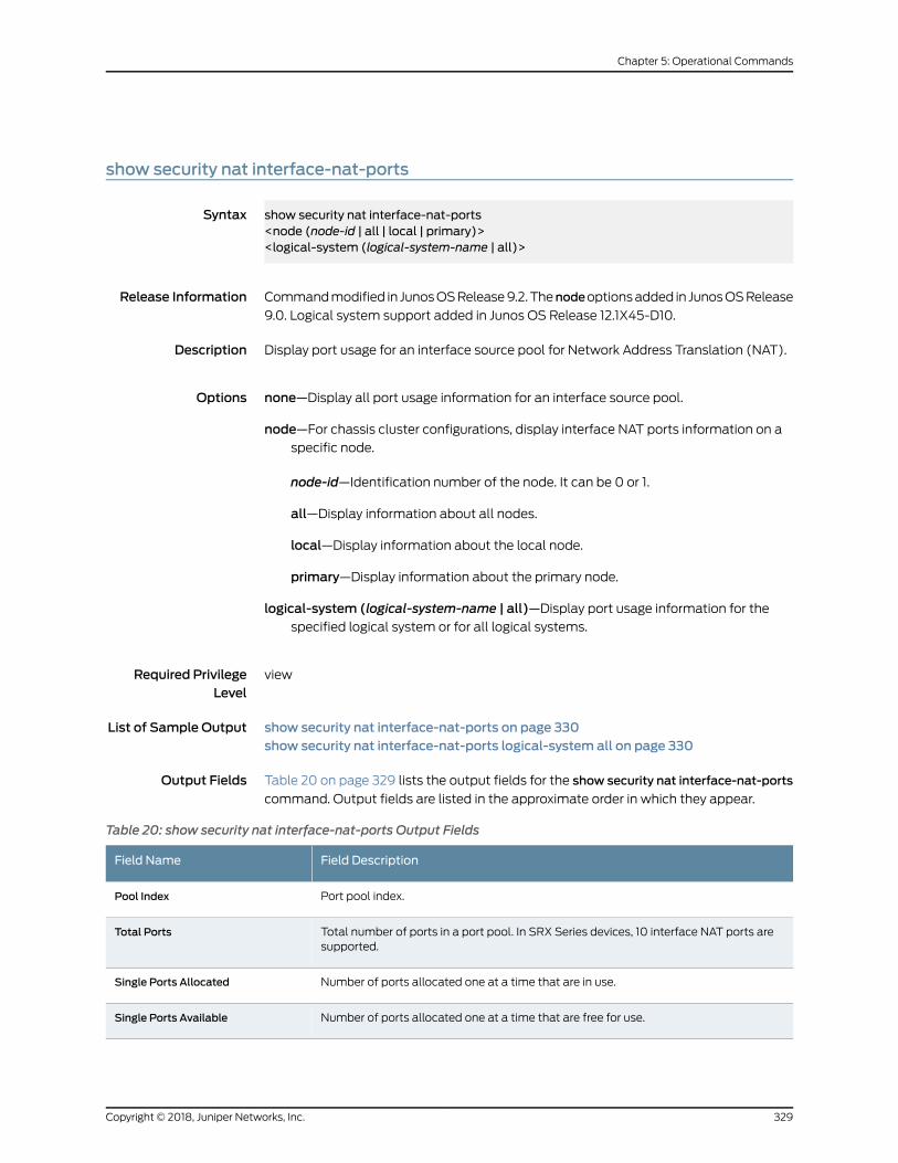
show security nat interface-nat-ports
Syntax show security nat interface-nat-ports<node (node-id | all | local | primary)><logical-system (logical-system-name | all)>
Release Information Commandmodified in JunosOSRelease9.2. Thenodeoptionsadded in JunosOSRelease
9.0. Logical system support added in Junos OS Release 12.1X45-D10.
Description Display port usage for an interface source pool for Network Address Translation (NAT).
Options none—Display all port usage information for an interface source pool.
node—For chassis cluster configurations, display interface NAT ports information on aspecific node.
node-id—Identification number of the node. It can be 0 or 1.
all—Display information about all nodes.
local—Display information about the local node.
primary—Display information about the primary node.
logical-system (logical-system-name | all)—Display port usage information for thespecified logical system or for all logical systems.
Required PrivilegeLevel
view
List of Sample Output show security nat interface-nat-ports on page 330show security nat interface-nat-ports logical-system all on page 330
Output Fields Table 20 on page 329 lists the output fields for the show security nat interface-nat-ports
command. Output fields are listed in the approximate order in which they appear.
Table 20: show security nat interface-nat-ports Output Fields
Field DescriptionField Name
Port pool index.Pool Index
Total number of ports in a port pool. In SRX Series devices, 10 interface NAT ports aresupported.
Total Ports
Number of ports allocated one at a time that are in use.Single Ports Allocated
Number of ports allocated one at a time that are free for use.Single Ports Available
329Copyright © 2018, Juniper Networks, Inc.
Chapter 5: Operational Commands

Table 20: show security nat interface-nat-ports Output Fields (continued)
Field DescriptionField Name
Number of ports allocated two at a time that are in use.Twin Ports Allocated
Number of ports allocated two at a time that are free for use.Twin Ports Available
Sample Output
show security nat interface-nat-ports
user@host> show security nat interface-nat-ports
Pool Total Single ports Single ports Twin ports Twin ports index ports allocated available allocated available 0 64510 0 63486 0 1024 1 64510 0 63486 0 1024 2 64510 0 63486 0 1024 3 64510 0 63486 0 1024 4 64510 0 63486 0 1024 5 64510 0 63486 0 1024 6 64510 0 63486 0 1024 7 64510 0 63486 0 1024 8 64510 0 63486 0 1024 9 64510 0 63486 0 1024
Sample Output
show security nat interface-nat-ports logical-system all
user@host> show security nat interface-nat-ports logical-system all
Logical system: root-logical-systemPool Total Single ports Single ports Twin ports Twin portsindex ports allocated available allocated available 0 64510 0 63486 0 1024Logical system: LSYS1Pool Total Single ports Single ports Twin ports Twin portsindex ports allocated available allocated available 0 64510 0 63486 0 1024 1 64510 0 63486 0 1024 2 64510 0 63486 0 1024 3 64510 0 63486 0 1024 4 64510 0 63486 0 1024 5 64510 0 63486 0 1024 6 64510 0 63486 0 1024 7 64510 0 63486 0 1024 8 64510 0 63486 0 1024 9 64510 0 63486 0 1024 10 64510 0 63486 0 1024 11 64510 0 63486 0 1024 12 64510 0 63486 0 1024 13 64510 0 63486 0 1024 14 64510 0 63486 0 1024 15 64510 0 63486 0 1024 16 64510 0 63486 0 1024 17 64510 0 63486 0 1024
Copyright © 2018, Juniper Networks, Inc.330
Network Address Translation Feature Guide for Security Devices

18 64510 0 63486 0 1024 19 64510 0 63486 0 1024 20 64510 0 63486 0 1024 21 64510 0 63486 0 1024 22 64510 0 63486 0 1024 23 64510 0 63486 0 1024 24 64510 0 63486 0 1024 25 64510 0 63486 0 1024 26 64510 0 63486 0 1024 27 64510 0 63486 0 1024 28 64510 0 63486 0 1024 29 64510 0 63486 0 1024 30 64510 0 63486 0 1024 31 64510 0 63486 0 1024 32 64510 0 63486 0 1024 33 64510 0 63486 0 1024 34 64510 0 63486 0 1024 35 64510 0 63486 0 1024 36 64510 0 63486 0 1024 37 64510 0 63486 0 1024 38 64510 0 63486 0 1024 39 64510 0 63486 0 1024 40 64510 0 63486 0 1024 41 64510 0 63486 0 1024 42 64510 0 63486 0 1024 43 64510 0 63486 0 1024 44 64510 0 63486 0 1024 45 64510 0 63486 0 1024 45 64510 0 63486 0 1024 46 64510 0 63486 0 1024 47 64510 0 63486 0 1024 48 64510 0 63486 0 1024 49 64510 0 63486 0 1024 50 64510 0 63486 0 1024 51 64510 0 63486 0 1024 52 64510 0 63486 0 1024 53 64510 0 63486 0 1024 54 64510 0 63486 0 1024 55 64510 0 63486 0 1024 56 64510 0 63486 0 1024 57 64510 0 63486 0 1024 58 64510 0 63486 0 1024 59 64510 0 63486 0 1024
331Copyright © 2018, Juniper Networks, Inc.
Chapter 5: Operational Commands

show security nat resource-usage source-pool
Syntax show security nat resource-usage source-poolall | source-pool-namelogical-system logical-system-name | root logical system
Release Information Command introduced in Junos OS Release 12.1X45-D10.
Description Display source NAT pool usage information. In pools without Port Address Translation
(PAT), information about IP addresses is displayed. In pools with PAT, information about
ports is displayed.
Options all—Display resource use information for all source NAT pools.
source-pool-name—Display resource use information for the specified source NAT pool.
logical-system logical-system-name—Display resource use information for the sourceNAT pools in the specified logical system.
root-logical-system—Display resource use information for the source NAT pools in theroot logical system.
Required PrivilegeLevel
view
Release History Table DescriptionRelease
Starting in Junos OS Release 15.1X49-D90 and Junos OS Release 17.3R1,the total number of addresses for pools with IPv6 prefixes is shown aszero (0).
15.1X49-D90
Starting in Junos OS Release 15.1X49-D90 and Junos OS Release 17.3R1,the total number of available resources for pools with IPv6 prefixes isshown as 0.
15.1X49-D90
RelatedDocumentation
clear security nat statistics source pool on page 312•
List of Sample Output show security nat resource-usage resource-pool all on page 333showsecuritynat resource-usageresource-poolpool-name(WithoutPAT)onpage334show security nat resource-usage resource-pool pool-name (with PAT) on page 334
Output Fields Table 21 on page 333 lists the output fields for the show security nat resource-usage
source-pool command. Output fields are listed in the approximate order in which they
appear. You can use the clear security nat statistics command to reset the peak usage
statistics.
Copyright © 2018, Juniper Networks, Inc.332
Network Address Translation Feature Guide for Security Devices
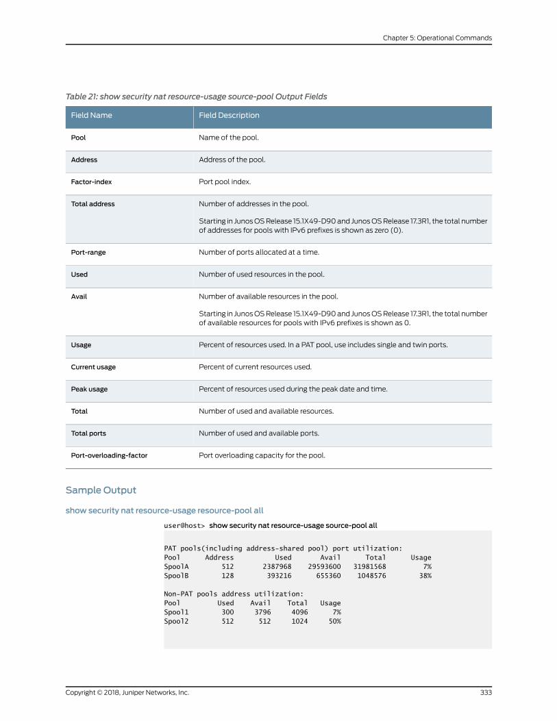
Table 21: show security nat resource-usage source-pool Output Fields
Field DescriptionField Name
Name of the pool.Pool
Address of the pool.Address
Port pool index.Factor-index
Number of addresses in the pool.
Starting in JunosOSRelease 15.1X49-D90and JunosOSRelease 17.3R1, the total numberof addresses for pools with IPv6 prefixes is shown as zero (0).
Total address
Number of ports allocated at a time.Port-range
Number of used resources in the pool.Used
Number of available resources in the pool.
Starting in JunosOSRelease 15.1X49-D90and JunosOSRelease 17.3R1, the total numberof available resources for pools with IPv6 prefixes is shown as 0.
Avail
Percent of resources used. In a PAT pool, use includes single and twin ports.Usage
Percent of current resources used.Current usage
Percent of resources used during the peak date and time.Peak usage
Number of used and available resources.Total
Number of used and available ports.Total ports
Port overloading capacity for the pool.Port-overloading-factor
Sample Output
show security nat resource-usage resource-pool all
user@host> show security nat resource-usage source-pool all
PAT pools(including address-shared pool) port utilization:Pool Address Used Avail Total UsageSpoolA 512 2387968 29593600 31981568 7%SpoolB 128 393216 655360 1048576 38%
Non-PAT pools address utilization:Pool Used Avail Total UsageSpool1 300 3796 4096 7%Spool2 512 512 1024 50%
333Copyright © 2018, Juniper Networks, Inc.
Chapter 5: Operational Commands

show security nat resource-usage resource-pool pool-name (Without PAT)
user@host> show security nat resource-usage source-pool Spool1
Logical system: rootPeak usage: 60% @ 2012-08-26 20:16:20 UTC
Pool Used Avail Total UsageSpool1 300 3796 4096 7%
show security nat resource-usage resource-pool pool-name (with PAT)
user@host> show security nat resource-usage source-pool sp3
Logical system: rootPool name: sp3Total address: 2 Port-overloading-factor: 2Total ports: 258048 Used: 60563 Avail: 197485Current usage: 23% Peak usage: 35% at 2012-11-12 20:15:26 CST Address Factor-index Port-range Used Avail Total Usage
192.0.2.113 0 Single Ports 30001 32463 62464 48%
- Alg Ports 462 1586 2048 22%
1 Single Ports 0 62464 62464 0%
- Alg Ports 0 2048 2048 0%
Sum Single Ports 30001 94927 124928 24%
- Alg Ports 462 3634 4096 11%
192.0.2.114 0 Single Ports 29600 32864 62464 47%
- Alg Ports 500 1548 2048 24%
1 Single Ports 0 62464 62464 0%
- Alg Ports 0 2048 2048 0%
Sum Single Ports 29600 95328 124928 23%
- Alg Ports 500 3596 4096 12%
Copyright © 2018, Juniper Networks, Inc.334
Network Address Translation Feature Guide for Security Devices

show security nat source deterministic
Syntax show security nat source deterministicpool-namehost-ip host ip addresshost-address-rangexlated-ip xlated-ip-addressxlated-port xlated-portnoderoot-logical-system | logical-system {lsys-name | all }
Release Information Command introduced in Junos OS Release 12.1X47-D10.
Description Verify the mapping relation when Deterministic-Nat is on.
Options host-address-range—Display deterministic host address range without overlap.
pool-name—Display Deterministic NAT port block table for the specified source poolname.
node—Display source NAT deterministic port block table on specific node.
host ip address—Display deterministic NAT port block table based on internal host ipaddress.
xlated ip address—Display deterministic NAT port block table based on translated IPaddress.
xlated-port—Display deterministic NAT port block table based on translated IP and port;xlated-port can be used only with xlated-ip together for display.
root-logical-system—Display information about the source NAT pools for the master(root) logical system.
logical-system(lsys-name | all)—Display informationabout thespecified logical systemsource NAT pools or all logical system source NAT pools.
Required PrivilegeLevel
view
RelatedDocumentation
show security nat source pool on page 343•
• show security nat source port-block on page 349
List of Sample Output show security nat source deterministic on page 336
Output Fields Table 22 on page 336 lists the output fields for the show security nat source deterministic
command. Output fields are listed in the approximate order in which they appear.
335Copyright © 2018, Juniper Networks, Inc.
Chapter 5: Operational Commands

Table 22: show security nat source deterministic Output Fields
Field DescriptionField Name
Name of pool.Pool name
Factor of port overloading for the source pool.Port-overloading-factor
Number of ports that a port block contains.Port block size
Port block used number and port block total number for this source NAT pool.Used/total port blocks
IP address of host.Host IP
IP address of external router.External IP
The range of ports in a block, ranging from lowest to highest.Port_Range
Number of ports used and total ports.Ports_Used/Total
Sample Output
show security nat source deterministic
user@host> show security nat source deterministic
Pool name: SRC_P_3Port-overloading-factor: 1 Port block size: 10000 Used/total port blocks: 0/12Host_IP External_IP Port_Range Ports_Used/Total10.2.0.1 203.0.113.1 1024-11023 0/10000*1
10.2.0.2 203.0.113.1 11024-21023 0/10000*1
Copyright © 2018, Juniper Networks, Inc.336
Network Address Translation Feature Guide for Security Devices

show security nat source paired-address
Syntax show security nat source paired-address<internal-ip internal-ip-address><logical-system logical-system-name><pool-name pool-name><root-logical-system><xlated-ip x-lated-ip-address>
Release Information Command introduced in Junos OS Release 12.1X45-D10.
Description Display information about the Network Address Translation (NAT) source paired
addresses.
Options none—Display all paired IP address information.
internal ip internal-ip-address—Display information about the specified internal IPaddress.
logical-system logical-system-name—Display information about the source NAT poolsfor the specified logical system.
pool-name pool-name—Display paired address information for the specified pool.
root-logical-system—Display information about the source NAT pools for the master(root) logical system.
x-lated-ipx-lated-ip-address—Display informationabout thespecified translatedexternalIP address.
Additional Information
Required PrivilegeLevel
view
RelatedDocumentation
List of Sample Output show security nat source paired-address on page 338show security nat source paired-address pool-name on page 338show security nat source paired-address pool-name internal-ip on page 338show security nat source paired-address pool-name xlated-ip on page 338
Output Fields Table23onpage338 lists theoutput fields for the showsecuritynatsourcepaired-address
command. Output fields are listed in the approximate order in which they appear.
337Copyright © 2018, Juniper Networks, Inc.
Chapter 5: Operational Commands

Table 23: show security nat source paired-address Output Fields
Field DescriptionField Name
Name of the source pool.Pool name
Internal IP address.Internal address
External IP address.External address
Sample Output
show security nat source paired-address
user@host> show security nat source paired-address
Pool name: sp1 Internal address External address198.51.100.240 203.0.113.105
Pool name: sp2 Internal address External address198.51.100.240 203.0.113.105 198.51.100.127 203.0.113.105 198.51.100.125 203.0.113.105 198.51.100.130 203.0.113.105 198.51.100.128 203.0.113.105 198.51.100.129 203.0.113.105
show security nat source paired-address pool-name
user@host> show security nat source paired-address pool-name sp1
Pool name: sp1Internal address External address192.168.1.1 192.0.2.1192.168.1.2 192.0.2.2192.168.1.3 192.0.2.3
show security nat source paired-address pool-name internal-ip
user@host> show security nat source paired-address pool-name sp1 internal-ip 192.168.1.1
Pool name: sp1Internal address External address192.168.1.1 192.0.2.1
show security nat source paired-address pool-name xlated-ip
user@host> show security nat source paired-address pool-name sp1 xlated-ip 192.0.2.2
Pool name: sp1Internal address External address192.168.1.2 192.0.2.2
Copyright © 2018, Juniper Networks, Inc.338
Network Address Translation Feature Guide for Security Devices

339Copyright © 2018, Juniper Networks, Inc.
Chapter 5: Operational Commands

show security nat source persistent-nat-table
Syntax show security nat source persistent-nat-table ( all | interface | internal-ip ip-address<internal-port port> | pool poolname )
Release Information Command introduced in Junos OS Release 9.6. Support for IPv6 addresses added in
Junos OS Release 11.2.
Description Display a summary of persistent Network Address Translation (NAT) information.
Options • all—Display all persistent NAT bindings.
• interface—Display persistent NAT bindings for the interface.
• internal-ip ip-address—Display persistent NAT bindings for the specified internal IP
address.
• internal-ip ip-address internal-portport—DisplaypersistentNATbindings for thespecified
internal IP address and port.
• pool—Display persistent NAT bindings for the specified source NAT pool.
• summary—Display persistent NAT bindings summary.
Required PrivilegeLevel
view
RelatedDocumentation
clear security nat source persistent-nat-table on page 309•
List of Sample Output show security nat source persistent–nat–table internal-ip internal-port on page 341show security nat source persistent–nat–table all on page 341show security nat source persistent-nat-table summary on page 342
Output Fields Table 24 on page 340 lists the output fields for the show security nat source
persistent–nat–tablecommand.Output fieldsare listed in theapproximateorder inwhich
they appear.
Table 24: show security nat source persistent–nat–table Output Fields
Field DescriptionField Name
Internal transport IP address and port number of the outgoing session from internal toexternal.
Internal IP/Port
Translated IP address and port number of the source IP address and port.Reflexive IP/Port
The name of the source pool where persistent NAT is used.Source NAT Pool
Persistent NAT type.Type
Copyright © 2018, Juniper Networks, Inc.340
Network Address Translation Feature Guide for Security Devices

Table 24: show security nat source persistent–nat–table Output Fields (continued)
Field DescriptionField Name
The inactivity timeout period that remains and the configured timeout value.Left_time/Conf_time
The number of current sessions associated with the persistent NAT binding.Current_Sess_Num/Max_Sess_Num
Name of the source NAT rule to which this persistent NAT binding applies.Source NAT Rule
Sample Output
show security nat source persistent–nat–table internal-ip internal-port
user@host> show security nat source persistent–nat–table internal-ip 192.0.2.1 internal-port60784
Internal Reflective Source Type Left_time/ Curr_Sess_Num/ Source In_IP In_Port I_Proto Ref_IP Ref_Port R_Proto NAT Pool Conf_time Max_Sess_Num NAT Rule192.0.2.1 60784 udp 198.51.100.68 60784 udp dynamic-customer-source any-remote-host 254/300 0/30 105
Sample Output
show security nat source persistent–nat–table all
user@host> show security nat source persistent–nat–table all
Internal Reflective Source Type Left_time/ Curr_Sess_Num/ Source In_IP In_Port I_Proto Ref_IP Ref_Port R_Proto NAT Pool Conf_time Max_Sess_Num NAT Rule192.0.2.1 63893 tcp 198.51.100.68 63893 tcp dynamic-customer-source any-remote-host 192/300 0/30 105192.0.2.1 64014 udp 198.51.100.68 64014 udp dynamic-customer-source any-remote-host 244/300 0/30 105192.0.2.1 60784 udp 198.51.100.68 60784 udp dynamic-customer-source any-remote-host 254/300 0/30 105192.0.2.1 57022 udp 198.51.100.68 57022 udp dynamic-customer-source any-remote-host 264/300 0/30 105192.0.2.1 53009 udp 198.51.100.68 53009 udp dynamic-customer-source any-remote-host 268/300 0/30 105192.0.2.1 49225 udp 198.51.100.68 49225 udp dynamic-customer-source any-remote-host 272/300 0/30 105192.0.2.1 52150 udp 198.51.100.68 52150 udp dynamic-customer-source any-remote-host 274/300 0/30 105192.0.2.1 59770 udp 198.51.100.68 59770 udp dynamic-customer-source any-remote-host 278/300 0/30 105192.0.2.1 61497 udp 198.51.100.68 61497 udp dynamic-customer-source any-remote-host 282/300 0/30 105192.0.2.1 56843 udp 198.51.100.68 56843 udp dynamic-customer-source any-remote-host -/300 1/30 105
341Copyright © 2018, Juniper Networks, Inc.
Chapter 5: Operational Commands
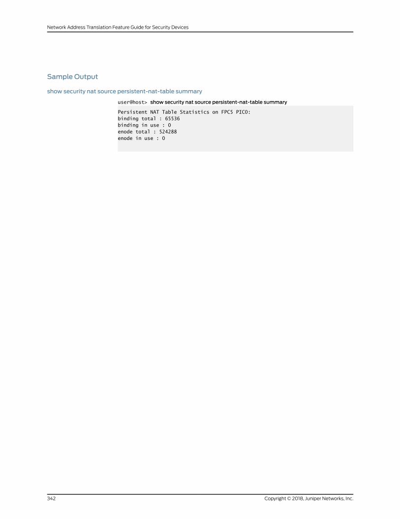
Sample Output
show security nat source persistent-nat-table summary
user@host> show security nat source persistent-nat-table summary
Persistent NAT Table Statistics on FPC5 PIC0:binding total : 65536 binding in use : 0enode total : 524288enode in use : 0
Copyright © 2018, Juniper Networks, Inc.342
Network Address Translation Feature Guide for Security Devices
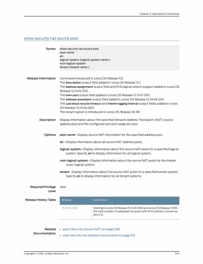
show security nat source pool
Syntax show security nat source poolpool-namealllogical-system (logical-system-name )root-logical-systemtenant (tenant-name )
Release Information Command introduced in Junos OS Release 9.2.
The Description output field added in Junos OS Release 12.1.
TheAddress assignment output field and IPv6 logical system support added in JunosOS
Release 12.1X45-D10.
The twin-port output field added in Junos OS Release 12.1X47-D10.
The Address-persistent output field added in Junos OS Release 12.3X48-D10.
The Last block recycle timeout and Interim logging interval output fields added in Junos
OS Release 15.1X49-D60.
The tenant option is introduced in Junos OS Release 18.3R1.
Description Display information about the specified Network Address Translation (NAT) source
address pool and the configured twin port range per pool.
Options pool-name—Display source NAT information for the specified address pool.
all—Display information about all source NAT address pools.
logical-system—Display information about the source NAT pools for a specified logicalsystem. Specify all to display information for all logical system.
root-logical-system—Display information about the source NAT pools for the master(root) logical system.
tenant—Display information about the source NAT pools for a specified tenant system.Specify all to display information for all tenant systems.
Required PrivilegeLevel
view
Release History Table DescriptionRelease
Starting in JunosOSRelease 15.1X49-D90and JunosOSRelease 17.3R1,the total number of addresses for pools with IPv6 prefixes is shown aszero (0).
15.1X49-D90
RelatedDocumentation
pool (Security Source NAT) on page 258•
• clear security nat statistics source pool on page 312
343Copyright © 2018, Juniper Networks, Inc.
Chapter 5: Operational Commands
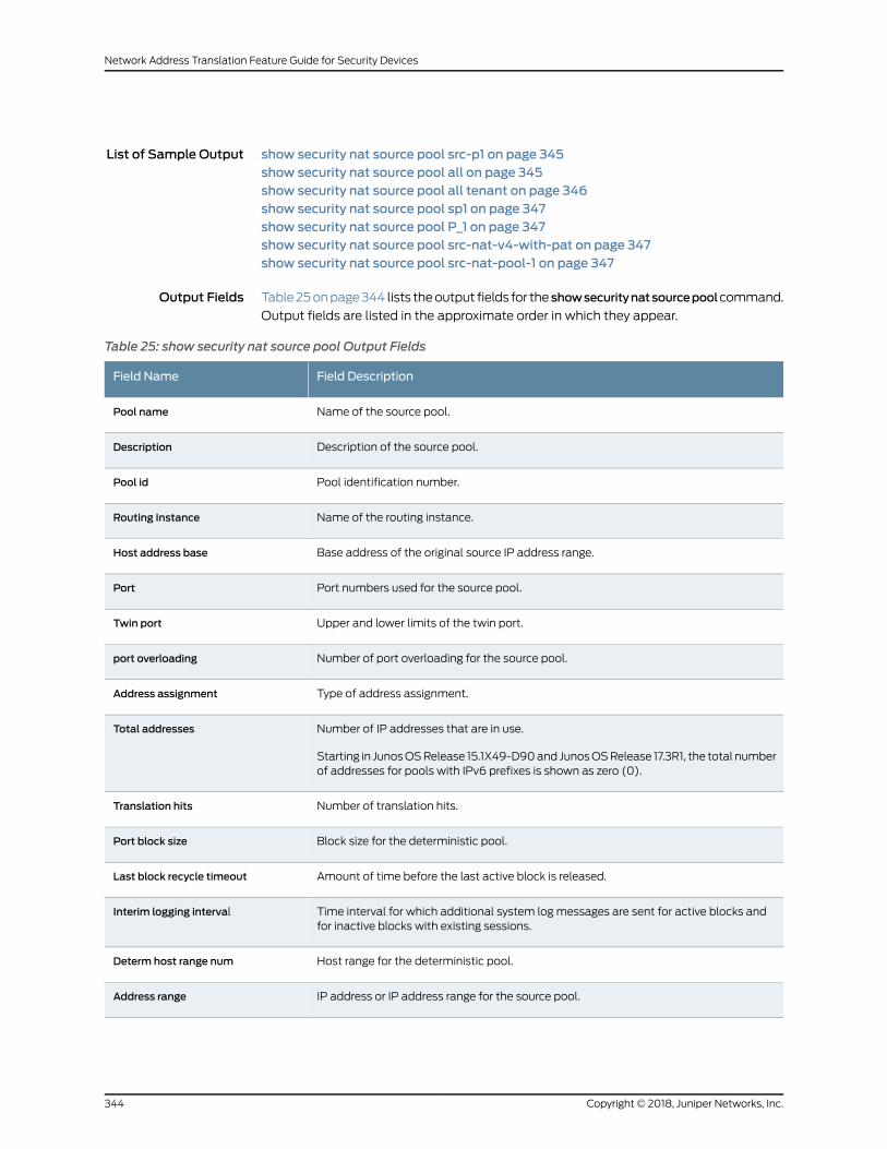
List of Sample Output show security nat source pool src-p1 on page 345show security nat source pool all on page 345show security nat source pool all tenant on page 346show security nat source pool sp1 on page 347show security nat source pool P_1 on page 347show security nat source pool src-nat-v4-with-pat on page 347show security nat source pool src-nat-pool-1 on page 347
Output Fields Table25onpage344 lists theoutput fields for the showsecuritynatsourcepoolcommand.
Output fields are listed in the approximate order in which they appear.
Table 25: show security nat source pool Output Fields
Field DescriptionField Name
Name of the source pool.Pool name
Description of the source pool.Description
Pool identification number.Pool id
Name of the routing instance.Routing Instance
Base address of the original source IP address range.Host address base
Port numbers used for the source pool.Port
Upper and lower limits of the twin port.Twin port
Number of port overloading for the source pool.port overloading
Type of address assignment.Address assignment
Number of IP addresses that are in use.
Starting in JunosOSRelease 15.1X49-D90and JunosOSRelease 17.3R1, the total numberof addresses for pools with IPv6 prefixes is shown as zero (0).
Total addresses
Number of translation hits.Translation hits
Block size for the deterministic pool.Port block size
Amount of time before the last active block is released.Last block recycle timeout
Time interval for which additional system logmessages are sent for active blocks andfor inactive blocks with existing sessions.
Interim logging interval
Host range for the deterministic pool.Determ host range num
IP address or IP address range for the source pool.Address range
Copyright © 2018, Juniper Networks, Inc.344
Network Address Translation Feature Guide for Security Devices
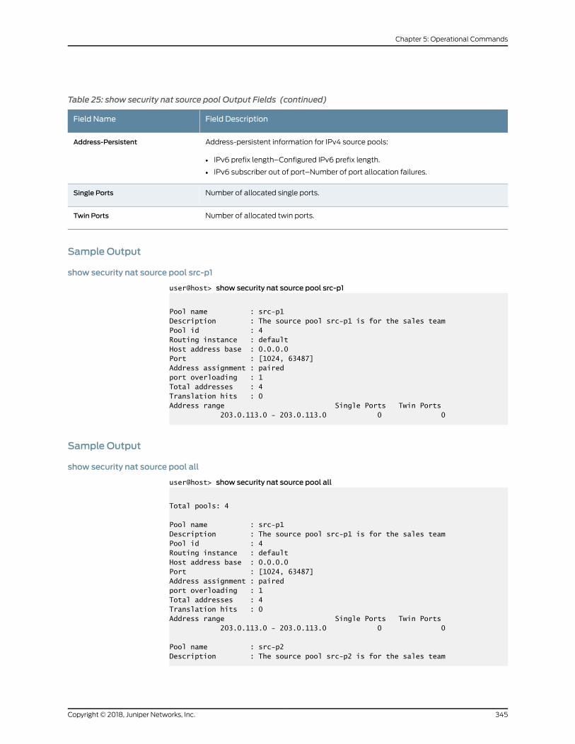
Table 25: show security nat source pool Output Fields (continued)
Field DescriptionField Name
Address-persistent information for IPv4 source pools:
• IPv6 prefix length–Configured IPv6 prefix length.
• IPv6 subscriber out of port–Number of port allocation failures.
Address-Persistent
Number of allocated single ports.Single Ports
Number of allocated twin ports.Twin Ports
Sample Output
show security nat source pool src-p1
user@host> show security nat source pool src-p1
Pool name : src-p1Description : The source pool src-p1 is for the sales teamPool id : 4Routing instance : defaultHost address base : 0.0.0.0Port : [1024, 63487] Address assignment : pairedport overloading : 1Total addresses : 4Translation hits : 0Address range Single Ports Twin Ports 203.0.113.0 - 203.0.113.0 0 0
Sample Output
show security nat source pool all
user@host> show security nat source pool all
Total pools: 4
Pool name : src-p1Description : The source pool src-p1 is for the sales teamPool id : 4Routing instance : defaultHost address base : 0.0.0.0Port : [1024, 63487] Address assignment : pairedport overloading : 1Total addresses : 4Translation hits : 0Address range Single Ports Twin Ports 203.0.113.0 - 203.0.113.0 0 0
Pool name : src-p2Description : The source pool src-p2 is for the sales team
345Copyright © 2018, Juniper Networks, Inc.
Chapter 5: Operational Commands

Pool id : 5Routing instance : defaultHost address base : 0.0.0.0Port : [1024, 63487] Address assignment : no-pairedport overloading : 1Total addresses : 4Translation hits : 0Address range Single Ports Twin Ports 192.0.2.0 - 192.0.2.3 0 0
Pool name : src-p3Description : The source pool src-p3 is for the sales teamPool id : 6Routing instance : defaultHost address base : 0.0.0.0Port : [1024, 63487] Address assignment : no-pairedport overloading : 1Total addresses : 1Translation hits : 0Address range Single Ports Twin Ports 2001:db8::1 - 2001:db8::1 0 0
Pool name : src-p4Description : The source pool src-p4 is for the sales teamPool id : 7Routing instance : defaultHost address base : 0.0.0.0Port : [1024, 63487] Address assignment : no-pairedport overloading : 1Total addresses : 1Translation hits : 0Address range Single Ports Twin Ports 2001:db8::2 - 2001:db8::2 0 0
show security nat source pool all tenant
user@host> show security nat source pool all tenant tn1
Total pools: 1Pool name : patPool id : 4Routing instance : defaultHost address base : 0.0.0.0Port : [1024, 63487]Twin port : [63488, 65535]Port overloading : 1Address assignment : no-pairedTotal addresses : 24Translation hits : 0Address range Single Ports Twin Ports 192.0.2.1 - 192.0.2.24 0 0Total used ports : 0 0
Copyright © 2018, Juniper Networks, Inc.346
Network Address Translation Feature Guide for Security Devices
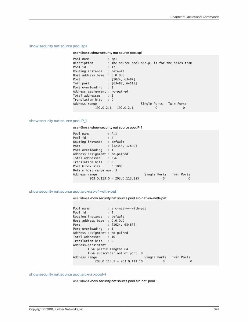
show security nat source pool sp1
user@host>show security nat source pool sp1
Pool name : sp1Description : The source pool src-p1 is for the sales teamPool id : 12Routing instance : defaultHost address base : 0.0.0.0Port : [1024, 63487] Twin port : [63488, 64515]Port overloading : 1Address assignment : no-pairedTotal addresses : 1Translation hits : 0Address range Single Ports Twin Ports 192.0.2.1 - 192.0.2.1 0 0
show security nat source pool P_1
user@host>show security nat source pool P_1
Pool name : P_1Pool id : 4Routing instance : defaultPort : [12345, 17890] Port overloading : 1Address assignment : no-pairedTotal addresses : 256Translation hits : 0Port block size : 1000Determ host range num: 3Address range Single Ports Twin Ports 203.0.113.0 - 203.0.113.255 0 0
show security nat source pool src-nat-v4-with-pat
user@host>how security nat source pool src-nat-v4-with-pat
Pool name : src-nat-v4-with-patPool id : 5Routing instance : defaultHost address base : 0.0.0.0Port : [1024, 63487] Port overloading : 1Address assignment : no-pairedTotal addresses : 10Translation hits : 0Address-persistent IPv6 prefix length: 64 IPv6 subscriber out of port: 0Address range Single Ports Twin Ports 203.0.113.1 - 203.0.113.10 0 0
show security nat source pool src-nat-pool-1
user@host>how security nat source pool src-nat-pool-1
347Copyright © 2018, Juniper Networks, Inc.
Chapter 5: Operational Commands

Pool name : src-nat-v4-with-patPool id : 5Routing instance : defaultHost address base : 0.0.0.0Port : [1024, 63487] Port overloading : 1Address assignment : no-pairedTotal pools : 1Pool name : src-nat-pool-1Pool id : 4Routing instance : defaultPort : [1024, 65535]Port overloading : 1Address assignment : no-pairedTotal addresses : 5Translation hits : 0Port block size : 256Max blocks per host : 8Active block timeout : 300Last block recycle timeout: 1800 Interim logging interval : 2400 PBA block log : EnableUsed/total port blocks: 0/1260Address range Single Ports Twin Ports 203.0.113.10 - 203.0.113.14 0 0 Total addresses : 10Translation hits : 0Address-persistent IPv6 prefix length: 64 IPv6 subscriber out of port: 0Address range Single Ports Twin Ports
Copyright © 2018, Juniper Networks, Inc.348
Network Address Translation Feature Guide for Security Devices
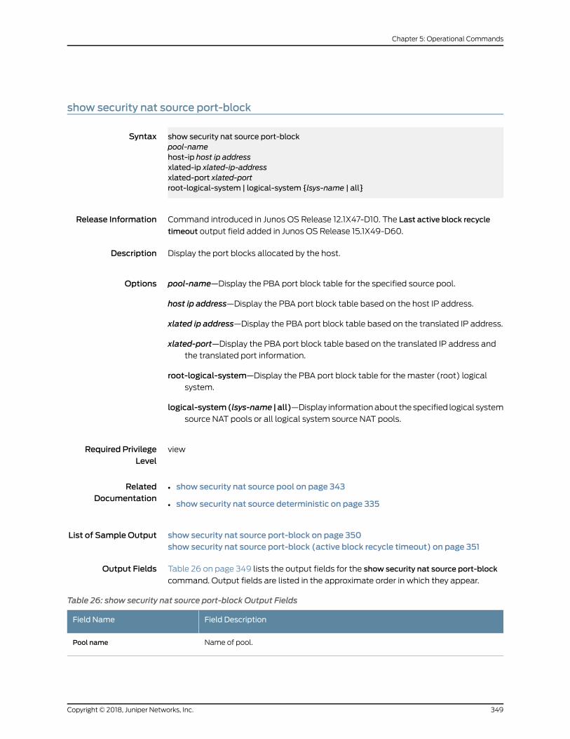
show security nat source port-block
Syntax show security nat source port-blockpool-namehost-ip host ip addressxlated-ip xlated-ip-addressxlated-port xlated-portroot-logical-system | logical-system {lsys-name | all}
Release Information Command introduced in Junos OS Release 12.1X47-D10. The Last active block recycle
timeout output field added in Junos OS Release 15.1X49-D60.
Description Display the port blocks allocated by the host.
Options pool-name—Display the PBA port block table for the specified source pool.
host ip address—Display the PBA port block table based on the host IP address.
xlated ip address—Display the PBA port block table based on the translated IP address.
xlated-port—Display the PBA port block table based on the translated IP address andthe translated port information.
root-logical-system—Display the PBA port block table for the master (root) logicalsystem.
logical-system(lsys-name | all)—Display informationabout thespecified logical systemsource NAT pools or all logical system source NAT pools.
Required PrivilegeLevel
view
RelatedDocumentation
show security nat source pool on page 343•
• show security nat source deterministic on page 335
List of Sample Output show security nat source port-block on page 350show security nat source port-block (active block recycle timeout) on page 351
Output Fields Table 26 on page 349 lists the output fields for the show security nat source port-block
command. Output fields are listed in the approximate order in which they appear.
Table 26: show security nat source port-block Output Fields
Field DescriptionField Name
Name of pool.Pool name
349Copyright © 2018, Juniper Networks, Inc.
Chapter 5: Operational Commands

Table 26: show security nat source port-block Output Fields (continued)
Field DescriptionField Name
Factor of port overloading for the source pool.Port-overloading-factor
Number of ports that a port block contains.Port block size
Maximum number of blocks that one host can use for translation.Max port blocks per host
Longest duration that a block remains active for port allocation.Port block active timeout
Current number of used ports and the total number of ports in this source pool.Used/total port blocks
Address of the host IP.Host IP
Address of an external IP.External IP
Port range of one PBA port block entry from the lowest to the highest port number thatcan be allowed to allocate ports for this block.
Port_Block Range
Current number of used ports and total number of ports in this source pool.Ports_Used/Ports_Total
PBA port block entry state for NAT port allocation, including Active, Inactive, Query, andthe time left for a port block that is in the Active state or Query state.
• Active—When an internal subscriber initiates a NAT request, a port block is allocatedfrom the pool, and the status is set to Active. When there is a subsequent requestfrom the same subscriber, a port is allocated from the existing Active block.
• Inactive—When there is a request from an internal subscriber who has previously hada port allocated from this port block, but the time on the Active port block has expiredor the ports are used up, the port block status changes from Active to Inactive.
• InactiveB—Whenachassis cluster is inactive/passivemode, andaportblock is createdon theactivenode, thestatus for thesyncedportblockon thebackupnode is InactiveB.
• Query—Whennoportsareused inanActiveport block, the status changes fromActiveto Query.
Block_State/Left_Time(s)
Amount of time before the last active block is released when active-port-block-timeoutis set to zero.
Last active block recycle timeout
Sample Output
show security nat source port-block
user@host> show security nat source port-block
Pool name: p1Port-overloading-factor: 1 Port block size: 128 Max port blocks per host: 4 Port block active timeout: 0Used/total port blocks: 1/118944Host_IP External_IP Port_Block Ports_Used/ Block_State/ Range Ports_Total Left_Time(s) 203.0.113.1 198.51.100.20 51328-51455 2/128*1 Active/-
Copyright © 2018, Juniper Networks, Inc.350
Network Address Translation Feature Guide for Security Devices
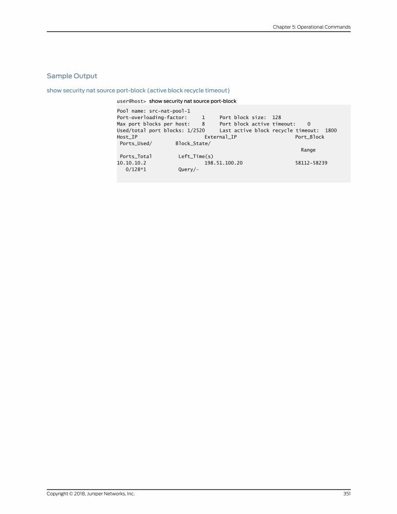
Sample Output
show security nat source port-block (active block recycle timeout)
user@host> show security nat source port-block
Pool name: src-nat-pool-1Port-overloading-factor: 1 Port block size: 128Max port blocks per host: 8 Port block active timeout: 0Used/total port blocks: 1/2520 Last active block recycle timeout: 1800 Host_IP External_IP Port_Block Ports_Used/ Block_State/ Range Ports_Total Left_Time(s)10.10.10.2 198.51.100.20 58112-58239 0/128*1 Query/-
351Copyright © 2018, Juniper Networks, Inc.
Chapter 5: Operational Commands

show security nat source rule
Syntax show security nat static rulerule-namealllogical-system (logical-system-name )root-logical-systemtenant (tenant-name )
Release Information Command introduced in Junos OS Release 9.2. Support for IPv6 addresses added in
Junos OS Release 11.2.
The Description output field added in Junos OS Release 12.1.
Support for IPv6 logical systemsand theSourceport,Successful sessions,Failedsessions,
and Number of sessions output fields added in Junos OS Release 12.1X45-D10.
Output formultiple destination ports and the application output field added in Junos OS
Release 12.1X47-D10.
The tenant option is introduced in Junos OS Release 18.3R1.
Description Display information about the specified source Network Address Translation (NAT) rule.
Options rule-name—Name of the rule.
all—Display information about all the source NAT rules.
logical-system—Display information about the source NAT rules for a specified logicalsystem. Specify all to display information for all logical systems.
root-logical-system—Display information about the source NAT rules for the master(root) logical system.
tenant—Display information about the source NAT rules for a specified tenant system.Specify all to display information for all tenant systems.
Required PrivilegeLevel
view
RelatedDocumentation
rule (Security Source NAT) on page 277•
List of Sample Output show security nat source rule r2 on page 354show security nat source rule all on page 354show security nat source rule all tenant on page 355
Output Fields Table 27onpage353 lists theoutput fields for the showsecuritynatsource rule command.
Output fields are listed in the approximate order in which they appear
Copyright © 2018, Juniper Networks, Inc.352
Network Address Translation Feature Guide for Security Devices

Table 27: show security nat source rule Output Fields
Field DescriptionField Name
Name of the source NAT rule.Source NAT rule
Number of source NAT rules.Total rules
Number of IP prefixes referenced in source, destination, and static NAT rules. This totalincludes the IP prefixes configured directly, as address names, and as address set namesin the rule.
Total referenced IPv4/IPv6ip-prefixes
Description of the source NAT rule.Description
Rule identification number.Rule-Id
Position of the source NAT rule.Rule position
Name of the zone fromwhich the packets flow.From zone
Name of the zone to which the packets flow.To zone
Name of the routing instance fromwhich the packets flow.From routing instance
Name of the routing instance to which the packets flow.To routing instance
Name of the interface fromwhich the packets flow.From interface
Name of the interface to which the packets flow.To interface
Name of the source addresses that match the rule.Source addresses
Source port numbers that match the rule.Source port
Name of the destination addresses that match the rule.Destination address
Destination port numbers that match the rule.Destination ports
Indicates whether the application option is configured.Application
The action taken in regard to a packet that matches the rule’s tuples. Actions includethe following:
• off—Do not perform source NAT.
• source NAT pool—Use user-defined source NAT pool to perform source NAT
• interface—Use egress interface's IP address to perform source NAT.
Action
Persistent NAT type.Persistent NAT type
Persistent NATmapping type.Persistent NATmapping type
Inactivity timeout for persistent NAT binding.Inactivity timeout
353Copyright © 2018, Juniper Networks, Inc.
Chapter 5: Operational Commands

Table 27: show security nat source rule Output Fields (continued)
Field DescriptionField Name
Maximum number of sessions.Max session number
Number of translation hits.Translation hits
Number of successful session installations after the NAT rule is matched.Successful sessions
Number of unsuccessful session installations after the NAT rule is matched.Failed sessions
Number of sessions that reference the specified rule.Number of sessions
Sample Output
show security nat source rule r2
user@host> show security nat source rule r2
source NAT rule: r2 Rule-set: src-nat Description : The source rule r2 is for the sales team Rule-Id : 1 Rule position : 1 From zone : zone1 To zone : zone9 Match Source addresses : add1 add2 Destination addresses : add9 add10 Destination port : 1002 - 1002 Action : off Persistent NAT type : N/A Persistent NAT mapping type : address-port-mapping Inactivity timeout : 0 Max session number : 0 Translation hits : 4719 Successful sessions : 2000 Failed sessions : 2719 Number of sessions : 5
Sample Output
show security nat source rule all
user@host> show security nat source rule all
Logical system: rootTotal rules: 1Total referenced IPv4/IPv6 ip-prefixes: 3/0
source NAT rule: r2 Rule-set: rs2 Rule-Id : 2 Rule position : 1 From zone : trust
Copyright © 2018, Juniper Networks, Inc.354
Network Address Translation Feature Guide for Security Devices

To zone : untrust Match Source addresses : 192.0.2.0 - 192.0.2.255 Destination addresses : 203.0.113.0 - 203.0.113.255 198.51.100.0 - 198.51.100.255 Application : configured Action : off Persistent NAT type : N/A Persistent NAT mapping type : address-port-mapping Inactivity timeout : 0 Max session number : 0 Translation hits : 0 Successful sessions : 0 Failed sessions : 0 Number of sessions : 0
Sample Output
show security nat source rule all tenant
user@host> show security nat source rule all tenant tn1
Total rules: 1Total referenced IPv4/IPv6 ip-prefixes: 2/0source NAT rule: r1 Rule-set: from_intf Rule-Id : 1 Rule position : 1 From interface : ge-0/0/0.0 To interface : ge-0/0/1.0 Match Source addresses : 192.168.1.0 - 192.168.1.255 Destination addresses : 203.0.113.200 - 203.0.113.200 Action : pat Persistent NAT type : N/A Persistent NAT mapping type : address-port-mapping Inactivity timeout : 0 Max session number : 0 Translation hits : 0 Successful sessions : 0 Failed sessions : 0 Number of sessions : 0
355Copyright © 2018, Juniper Networks, Inc.
Chapter 5: Operational Commands

show security nat source rule-application
Syntax show security nat source rule-applicationrule-namealllogical-system logical-system-nameroot-logical-system
Release Information Command introduced in Junos OS Release 12.1X47-D10.
Description Display information about the specified source Network Address Translation (NAT) rule
application.
Options rule-name—Display information about the specified source NAT rule application.
all—Display information about all the source NAT rule applications.
logical-system logical-system-name—Display information about the source NAT ruleapplications for the specified logical system.
root-logical-system—Display information about the source NAT rule applications forthe master (root) logical system.
Required PrivilegeLevel
view
RelatedDocumentation
Logical Systems and Tenant Systems Feature Guide for Security Devices•
List of Sample Output show security nat source rule-application for port application on page 357show security nat source rule-application for ICMP application on page 357
Output Fields Table28onpage356 lists theoutput fields for the showsecuritynatsource rule-application
command. Output fields are listed in the approximate order in which they appear.
Table 28: show security nat source rule-application Output Fields
Field DescriptionField Name
Name of the source NAT rule.Destination NAT rule
Rule set identification number.Rule-set
Rule identification number.Rule-Id
Name of the application or application set.Application
IP protocol identifier.IP protocol
Copyright © 2018, Juniper Networks, Inc.356
Network Address Translation Feature Guide for Security Devices

Table 28: show security nat source rule-application Output Fields (continued)
Field DescriptionField Name
Source port range identifier.Source port range
Destination port identifier.Destination port range
• type—ICMPmessage type.
• code—Code corresponding to the ICMPmessage type.
ICMP information
Sample Output
show security nat source rule-application for port application
user@host>show security nat source rule-application all
source NAT rule: r2 Rule-set: rs2 Rule-Id : 2 Application: app1 IP protocol: 3 Source port range: [90-90] Destination port range: [0-0] IP protocol: 4 Source port range: [100-100] Destination port range: [200-200] Application: app2 IP protocol: 7 Source port range: [400-500] Destination port range: [80-80]
Sample Output
show security nat source rule-application for ICMP application
user@host>show security nat source rule-application all
source NAT rule: r1 Rule-set: rs1 Rule-Id : 1 Application: junos-icmp-all IP protocol: icmp ICMP Information: type=255, code=0 Application: icmp1 IP protocol: icmp ICMP Information: type=1, code=1 Application: junos-icmp6-all IP protocol: 58 ICMP Information: type=255, code=0
357Copyright © 2018, Juniper Networks, Inc.
Chapter 5: Operational Commands

show security nat source summary
Syntax show security nat source summarylogical-system (logical-system-name )root-logical-systemtenant (tenant-name )
Release Information Command introduced in Junos OS Release 9.2.
Support for IPv6 logical systems added in Junos OS Release 12.1X45-D10.
The tenant option is introduced in Junos OS Release 18.3R1.
Description Display a summary of Network Address Translation (NAT) source information.
Options none—Display summary source NAT information.
logical-system—Display summary information about the source NAT for a specifiedlogical system. Specify all to display information for all logical systems.
root-logical-system—Display summary informationabout the sourceNAT for themaster(root) logical system.
tenant—Display summary information about the source NAT for a specified tenantsystem. Specify all to display information for all tenant systems.
Required PrivilegeLevel
view
Release History Table DescriptionRelease
Starting in Junos OS Release 12.3X48-D55, and Junos OS Release15.1X49-D90, and JunosOSRelease 17.3R1, the total number of addressesthat are in use for pools with IPv6 prefixes is shown as zero (0).
12.3X48-D55
RelatedDocumentation
pool (Security Source NAT) on page 258•
• rule (Security Source NAT) on page 277
List of Sample Output show security nat source summary on page 359show security nat source summary tenant on page 360
Output Fields Table 29 on page 359 lists the output fields for the show security nat source summary
command. Output fields are listed in the approximate order in which they appear.
Copyright © 2018, Juniper Networks, Inc.358
Network Address Translation Feature Guide for Security Devices

Table 29: show security nat source summary Output Fields
Field DescriptionField Name
Number of source NAT pools.Total source nat pool number
Name of the source address pool.Pool name
IP address or IP address range for the pool.Address range
Name of the routing instance.Routing Instance
Whether Port Address Translation (PAT) is enabled (yes or no).PAT
Number of IP addresses that are in use.
Starting in Junos OS Release 12.3X48-D55, and Junos OS Release 15.1X49-D90, andJunos OS Release 17.3R1, the total number of addresses that are in use for pools withIPv6 prefixes is shown as zero (0).
Total Address
Number of source NAT rules.Total source nat rule number
Number of ports assigned to the pool.Total port number usage for porttranslation pool
Maximum number of NAT or PAT transactions done at any given time.Maximumport number for porttranslation pool
Sample Output
show security nat source summary
user@host> show security nat source summary logical-system all
Logical system: root-logical-systemTotal port number usage for port translation pool: 67108864Maximum port number for port translation pool: 134217728
Logical system: lsys1Total port number usage for port translation pool: 193536Maximum port number for port translation pool: 134217728Total pools: 2
Logical system: root-logical-systemPool Address Routing PAT TotalName Range Instance Addresspool1 10.1.1.0-10.1.4.255- default yes 2048 10.1.5.0-10.1.8.255
Logical system: lsys1Pool Address Routing PAT TotalName Range Instance Addresspool2 203.0.113.1-203.0.113.3 default yes 3
359Copyright © 2018, Juniper Networks, Inc.
Chapter 5: Operational Commands

Total rules: 1
Logical system: root-logical-systemRule name Rule set From To Actionrule 1 ruleset1 ge-2/2/2.0 ge-2/2/3.0 pool1rule 1 ge-2/2/4.0 ge-2/2/5.0
show security nat source summary tenant
user@host> show security nat source summary tenant tn1
Total port number usage for port translation pool: 1548288Maximum port number for port translation pool: 268435456Total pools: 1Pool Address Routing PAT TotalName Range Instance Addresspat 192.0.2.1-192.0.2.24 default yes 24
Total rules: 1Rule name Rule set From To Actionr1 from_intf ge-0/0/0.0 ge-0/0/1.0 pat
Copyright © 2018, Juniper Networks, Inc.360
Network Address Translation Feature Guide for Security Devices

show security nat static rule
Syntax show security nat static rulerule-namealllogical-system (logical-system-name )root-logical-systemtenant (tenant-name )
Release Information Command introduced in Junos OS Release 9.3.
The Description output field added in Junos OS Release 12.1.
Support for IPv6 logical systems and the Successful sessions, Failed sessions, Number
of sessions, Source addresses and Source ports output fields added in Junos OS Release
12.1X45-D10.
TheDestinationNPTv6addrandDestinationNPTv6Netmaskoutput fieldsadded in Junos
OS Release 12.3X48-D25.
The tenant option is introduced in Junos OS Release 18.3R1.
Description Display information about the specified static Network Address Translation (NAT) rule.
Trafficdirectionsallowsyou tospecify from interface, fromzone,or fromrouting-instance
and packet information can be source addresses and ports, and destination addresses
and ports.
Options rule-name—Name of the rule.
all—Display information about all the static NAT rules.
logical-system—Display information about the static NAT rules for a specified logicalsystem. Specify all to display information for all logical systems.
root-logical-system—Display information about the static NAT rules for the master(root) logical system.
tenant—Display information about the static NAT rules for a specified tenant system.Specify all to display information for all tenant systems.
Required PrivilegeLevel
view
RelatedDocumentation
rule (Security Static NAT) on page 279•
List of Sample Output show security nat static rule on page 363show security nat static rule all tenant on page 363show security nat static rule (IPv6) on page 363show security nat static rule all on page 364
361Copyright © 2018, Juniper Networks, Inc.
Chapter 5: Operational Commands
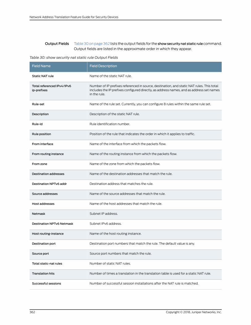
Output Fields Table30onpage362 lists theoutput fields for the showsecuritynatstatic rulecommand.
Output fields are listed in the approximate order in which they appear.
Table 30: show security nat static rule Output Fields
Field DescriptionField Name
Name of the static NAT rule.Static NAT rule
Number of IP prefixes referenced in source, destination, and static NAT rules. This totalincludes the IP prefixes configured directly, as address names, and as address set namesin the rule.
Total referenced IPv4/IPv6ip-prefixes
Name of the rule set. Currently, you can configure 8 rules within the same rule set.Rule-set
Description of the static NAT rule.Description
Rule identification number.Rule-Id
Position of the rule that indicates the order in which it applies to traffic.Rule position
Name of the interface fromwhich the packets flow.From interface
Name of the routing instance fromwhich the packets flow.From routing instance
Name of the zone fromwhich the packets flow.From zone
Name of the destination addresses that match the rule.Destination addresses
Destination address that matches the rule.Destination NPTv6 addr
Name of the source addresses that match the rule.Source addresses
Name of the host addresses that match the rule.Host addresses
Subnet IP address.Netmask
Subnet IPv6 address.Destination NPTv6 Netmask
Name of the host routing instance.Host routing-instance
Destination port numbers that match the rule. The default value is any.Destination port
Source port numbers that match the rule.Source port
Number of static NAT rules.Total static-nat rules
Number of times a translation in the translation table is used for a static NAT rule.Translation hits
Number of successful session installations after the NAT rule is matched.Successful sessions
Copyright © 2018, Juniper Networks, Inc.362
Network Address Translation Feature Guide for Security Devices
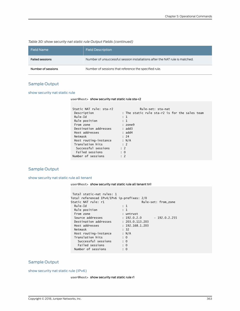
Table 30: show security nat static rule Output Fields (continued)
Field DescriptionField Name
Number of unsuccessful session installations after the NAT rule is matched.Failed sessions
Number of sessions that reference the specified rule.Number of sessions
Sample Output
show security nat static rule
user@host> show security nat static rule sta-r2
Static NAT rule: sta-r2 Rule-set: sta-nat Description : The static rule sta-r2 is for the sales team Rule-Id : 1 Rule position : 1 From zone : zone9 Destination addresses : add3 Host addresses : add4 Netmask : 24 Host routing-instance : N/A Translation hits : 2 Successful sessions : 2 Failed sessions : 0 Number of sessions : 2
Sample Output
show security nat static rule all tenant
user@host> show security nat static rule all tenant tn1
Total static-nat rules: 1Total referenced IPv4/IPv6 ip-prefixes: 2/0Static NAT rule: r1 Rule-set: from_zone Rule-Id : 1 Rule position : 1 From zone : untrust Source addresses : 192.0.2.0 - 192.0.2.255 Destination addresses : 203.0.113.203 Host addresses : 192.168.1.203 Netmask : 32 Host routing-instance : N/A Translation hits : 0 Successful sessions : 0 Failed sessions : 0 Number of sessions : 0
Sample Output
show security nat static rule (IPv6)
user@host> show security nat static rule r1
363Copyright © 2018, Juniper Networks, Inc.
Chapter 5: Operational Commands
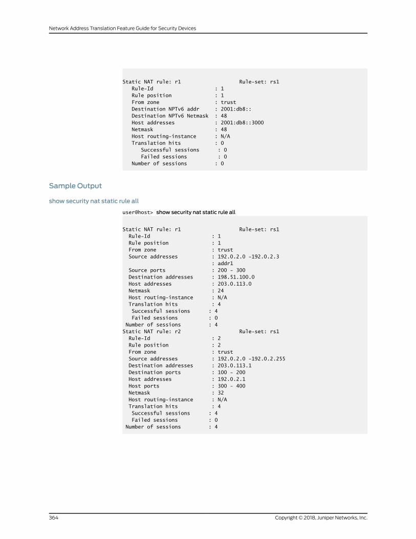
Static NAT rule: r1 Rule-set: rs1 Rule-Id : 1 Rule position : 1 From zone : trust Destination NPTv6 addr : 2001:db8:: Destination NPTv6 Netmask : 48 Host addresses : 2001:db8::3000 Netmask : 48 Host routing-instance : N/A Translation hits : 0 Successful sessions : 0 Failed sessions : 0 Number of sessions : 0
Sample Output
show security nat static rule all
user@host> show security nat static rule all
Static NAT rule: r1 Rule-set: rs1 Rule-Id : 1 Rule position : 1 From zone : trust Source addresses : 192.0.2.0 -192.0.2.3 : addr1 Source ports : 200 - 300 Destination addresses : 198.51.100.0 Host addresses : 203.0.113.0 Netmask : 24 Host routing-instance : N/A Translation hits : 4 Successful sessions : 4 Failed sessions : 0 Number of sessions : 4Static NAT rule: r2 Rule-set: rs1 Rule-Id : 2 Rule position : 2 From zone : trust Source addresses : 192.0.2.0 -192.0.2.255 Destination addresses : 203.0.113.1 Destination ports : 100 - 200 Host addresses : 192.0.2.1 Host ports : 300 - 400 Netmask : 32 Host routing-instance : N/A Translation hits : 4 Successful sessions : 4 Failed sessions : 0 Number of sessions : 4
Copyright © 2018, Juniper Networks, Inc.364
Network Address Translation Feature Guide for Security Devices