Embed Size (px)
Citation preview
Junos®OS
Tunnel andEncryptionServices Interfaces FeatureGuide for Routing Devices
Modified: 2018-02-23
Copyright © 2018, Juniper Networks, Inc.

Juniper Networks, Inc.1133 InnovationWaySunnyvale, California 94089USA408-745-2000www.juniper.net
Juniper Networks, the Juniper Networks logo, Juniper, and Junos are registered trademarks of Juniper Networks, Inc. and/or its affiliates inthe United States and other countries. All other trademarks may be property of their respective owners.
Juniper Networks assumes no responsibility for any inaccuracies in this document. Juniper Networks reserves the right to change, modify,transfer, or otherwise revise this publication without notice.
Junos®OS Tunnel and Encryption Services Interfaces Feature Guide for Routing Devices
Copyright © 2018 Juniper Networks, Inc. All rights reserved.
The information in this document is current as of the date on the title page.
YEAR 2000 NOTICE
Juniper Networks hardware and software products are Year 2000 compliant. Junos OS has no known time-related limitations through theyear 2038. However, the NTP application is known to have some difficulty in the year 2036.
ENDUSER LICENSE AGREEMENT
The Juniper Networks product that is the subject of this technical documentation consists of (or is intended for use with) Juniper Networkssoftware. Use of such software is subject to the terms and conditions of the End User License Agreement (“EULA”) posted athttp://www.juniper.net/support/eula/. By downloading, installing or using such software, you agree to the terms and conditions of thatEULA.
Copyright © 2018, Juniper Networks, Inc.ii
Table of Contents
About the Documentation . . . . . . . . . . . . . . . . . . . . . . . . . . . . . . . . . . . . . . . . . . . . xiii
Documentation and Release Notes . . . . . . . . . . . . . . . . . . . . . . . . . . . . . . . . . xiii
Supported Platforms . . . . . . . . . . . . . . . . . . . . . . . . . . . . . . . . . . . . . . . . . . . . xiii
Using the Examples in This Manual . . . . . . . . . . . . . . . . . . . . . . . . . . . . . . . . . xiii
Merging a Full Example . . . . . . . . . . . . . . . . . . . . . . . . . . . . . . . . . . . . . . . xiv
Merging a Snippet . . . . . . . . . . . . . . . . . . . . . . . . . . . . . . . . . . . . . . . . . . . xiv
Documentation Conventions . . . . . . . . . . . . . . . . . . . . . . . . . . . . . . . . . . . . . . xv
Documentation Feedback . . . . . . . . . . . . . . . . . . . . . . . . . . . . . . . . . . . . . . . . xvii
Requesting Technical Support . . . . . . . . . . . . . . . . . . . . . . . . . . . . . . . . . . . . xvii
Self-Help Online Tools and Resources . . . . . . . . . . . . . . . . . . . . . . . . . . xvii
Opening a Case with JTAC . . . . . . . . . . . . . . . . . . . . . . . . . . . . . . . . . . . . xviii
Part 1 Tunnel Services
Chapter 1 Overview . . . . . . . . . . . . . . . . . . . . . . . . . . . . . . . . . . . . . . . . . . . . . . . . . . . . . . . . . . 3
Tunnel Services Overview . . . . . . . . . . . . . . . . . . . . . . . . . . . . . . . . . . . . . . . . . . . . . 3
Tunnel Interface Configuration on MX Series Routers Overview . . . . . . . . . . . . . . . 6
Configuring Tunnel Interfaces on T4000 Routers . . . . . . . . . . . . . . . . . . . . . . . . . . 8
Configuring Tunnel Interfaces on an MX Series Router with a 16x10GE 3D
MPC . . . . . . . . . . . . . . . . . . . . . . . . . . . . . . . . . . . . . . . . . . . . . . . . . . . . . . . . . . . 9
Configuring Tunnel Interfaces on MX Series Routers with the MPC3E . . . . . . . . . . 10
Example: Configuring Tunnel Interfaces on the MPC3E . . . . . . . . . . . . . . . . . . . . . . 11
Configuring Tunnel Interfaces on MX Series Routers with MPC4E . . . . . . . . . . . . . 13
Tunnel Interfaces on MX Series Routers with MPC7E-10G, MPC7E-MRATE,
MX2K-MPC8E, and MX2K-MPC9E . . . . . . . . . . . . . . . . . . . . . . . . . . . . . . . . . . 13
Packet Forwarding Engine Mapping and Tunnel Bandwidth for
MPC7E-MRATE . . . . . . . . . . . . . . . . . . . . . . . . . . . . . . . . . . . . . . . . . . . . . . 14
Packet Forwarding Engine Mapping and Tunnel Bandwidth for
MPC7E-10G . . . . . . . . . . . . . . . . . . . . . . . . . . . . . . . . . . . . . . . . . . . . . . . . . 14
Packet Forwarding Engine Mapping and Tunnel Bandwidth for
MX2K-MPC8E . . . . . . . . . . . . . . . . . . . . . . . . . . . . . . . . . . . . . . . . . . . . . . . 14
Packet Forwarding Engine Mapping and Tunnel Bandwidth for
MX2K-MPC9E . . . . . . . . . . . . . . . . . . . . . . . . . . . . . . . . . . . . . . . . . . . . . . . 15
Configuring Tunnel Interfaces on MX Series Routers with
MPC7E-MRATE/MPC7E-10G . . . . . . . . . . . . . . . . . . . . . . . . . . . . . . . . . . . . . . . 15
Configuring Tunnel Interfaces on MX Series Routers with MX2K-MPC8E . . . . . . . 16
Configuring Tunnel Interfaces on MX Series Routers with MX2K-MPC9E . . . . . . . 17
Example: Configuring Tunnel Interfaces on a Gigabit Ethernet 40-Port DPC . . . . 18
Example: Configuring Tunnel Interfaces on a 10-Gigabit Ethernet 4-Port DPC . . . 19
iiiCopyright © 2018, Juniper Networks, Inc.
Chapter 2 Encapsulating One Protocol Over Another Using GRE Interfaces . . . . . . . . 21
GRE Keepalive Time Overview . . . . . . . . . . . . . . . . . . . . . . . . . . . . . . . . . . . . . . . . . 21
Configuring GRE Keepalive Time . . . . . . . . . . . . . . . . . . . . . . . . . . . . . . . . . . . . . . . 22
Configuring Keepalive Time and Hold time for a GRE Tunnel Interface . . . . . 23
Display GRE Keepalive Time Configuration . . . . . . . . . . . . . . . . . . . . . . . . . . . 24
Display Keepalive Time Information on a GRE Tunnel Interface . . . . . . . . . . . 24
Enabling Fragmentation on GRE Tunnels . . . . . . . . . . . . . . . . . . . . . . . . . . . . . . . . 25
Chapter 3 Encapsulating One IP Packet Over Another Using IP-IP Interfaces . . . . . . . 27
Configuring IPv6-over-IPv4 Tunnels . . . . . . . . . . . . . . . . . . . . . . . . . . . . . . . . . . . . 27
Example: Configuring an IPv6-over-IPv4 Tunnel . . . . . . . . . . . . . . . . . . . . . . . . . . 27
Chapter 4 Filtering Unicast Packets Through Multicast Tunnel Interfaces . . . . . . . . . . 29
Configuring Unicast Tunnels . . . . . . . . . . . . . . . . . . . . . . . . . . . . . . . . . . . . . . . . . . 29
Configuring a Key Number on GRE Tunnels . . . . . . . . . . . . . . . . . . . . . . . . . . . 31
Enabling Packet Fragmentation on GRE Tunnels Prior to GRE
Encapsulation . . . . . . . . . . . . . . . . . . . . . . . . . . . . . . . . . . . . . . . . . . . . . . 32
Specifying an MTU Setting for the Tunnel . . . . . . . . . . . . . . . . . . . . . . . . . . . . 32
Configuring a GRE Tunnel to Copy ToS Bits to the Outer IP Header . . . . . . . . 33
Enabling Fragmentation and Reassembly on Packets After
GRE-Encapsulation . . . . . . . . . . . . . . . . . . . . . . . . . . . . . . . . . . . . . . . . . . 33
Support for IPv6 GRE tunnels . . . . . . . . . . . . . . . . . . . . . . . . . . . . . . . . . . . . . 34
Examples: Configuring Unicast Tunnels . . . . . . . . . . . . . . . . . . . . . . . . . . . . . . . . . 34
Restricting Tunnels to Multicast Traffic . . . . . . . . . . . . . . . . . . . . . . . . . . . . . . . . . . 35
Chapter 5 Connecting Logical Systems Using Logical Tunnel Interfaces . . . . . . . . . . . 37
Configuring Logical Tunnel Interfaces . . . . . . . . . . . . . . . . . . . . . . . . . . . . . . . . . . . 37
Connecting Logical Systems . . . . . . . . . . . . . . . . . . . . . . . . . . . . . . . . . . . . . . . 37
Example: Configuring Logical Tunnels . . . . . . . . . . . . . . . . . . . . . . . . . . . . . . . . . . 39
Redundant Logical Tunnels Overview . . . . . . . . . . . . . . . . . . . . . . . . . . . . . . . . . . . 41
Redundant Logical Tunnel Configuration . . . . . . . . . . . . . . . . . . . . . . . . . . . . . 42
Redundant Logical Tunnel Failure Detection and Failover . . . . . . . . . . . . . . . 43
Configuring Redundant Logical Tunnels . . . . . . . . . . . . . . . . . . . . . . . . . . . . . . . . . 44
Example: Configuring Redundant Logical Tunnels . . . . . . . . . . . . . . . . . . . . . . . . . 45
Chapter 6 Configuring Layer 2 Ethernet Services over GRE Tunnel Interfaces . . . . . . . 57
Layer 2 Services over GRE Tunnel Interfaces on MX Series with MPCs . . . . . . . . . 57
Format of GRE Frames and Processing of GRE Interfaces for Layer 2 Ethernet
Packets . . . . . . . . . . . . . . . . . . . . . . . . . . . . . . . . . . . . . . . . . . . . . . . . . . . . . . . 58
Guidelines for Configuring Layer 2 Ethernet Traffic Over GRE Tunnels . . . . . . . . . 59
Sample Scenarios of Configuring Layer 2 Ethernet Traffic Over GRE Tunnels . . . 60
Configuring Layer 2 Services over GRE Logical Interfaces in Bridge Domains . . . . 61
Example: Configuring Layer 2 Services Over GRE Logical Interfaces in Bridge
Domains . . . . . . . . . . . . . . . . . . . . . . . . . . . . . . . . . . . . . . . . . . . . . . . . . . . . . . 62
Chapter 7 Understanding Default PIM Tunnel Configurations . . . . . . . . . . . . . . . . . . . . 69
Configuring PIM Tunnels . . . . . . . . . . . . . . . . . . . . . . . . . . . . . . . . . . . . . . . . . . . . . 69
Copyright © 2018, Juniper Networks, Inc.iv
Tunnel and Encryption Services Interfaces Feature Guide for Routing Devices
Chapter 8 Facilitating VRF Table Lookup Using Virtual Loopback TunnelInterfaces . . . . . . . . . . . . . . . . . . . . . . . . . . . . . . . . . . . . . . . . . . . . . . . . . . . . . . . . . 71
Configuring Virtual Loopback Tunnels for VRF Table Lookup . . . . . . . . . . . . . . . . . 71
Configuring Tunnel Interfaces for Routing Table Lookup . . . . . . . . . . . . . . . . . . . . 73
Example: Configuring a Virtual Loopback Tunnel for VRF Table Lookup . . . . . . . . 73
Example: Virtual Routing and Forwarding (VRF) and Service Configuration . . . . 74
Chapter 9 Enabling a VPN to Travel Through a Non-MPLS Network Using DynamicTunnels . . . . . . . . . . . . . . . . . . . . . . . . . . . . . . . . . . . . . . . . . . . . . . . . . . . . . . . . . . 77
Configuring Dynamic Tunnels . . . . . . . . . . . . . . . . . . . . . . . . . . . . . . . . . . . . . . . . . . 77
Part 2 Encryption Services
Chapter 10 Overview . . . . . . . . . . . . . . . . . . . . . . . . . . . . . . . . . . . . . . . . . . . . . . . . . . . . . . . . . 81
Encryption Overview . . . . . . . . . . . . . . . . . . . . . . . . . . . . . . . . . . . . . . . . . . . . . . . . . 81
Configuring an ES Tunnel Interface for a Layer 3 VPN . . . . . . . . . . . . . . . . . . . . . . . 81
Chapter 11 Sending Encrypted Traffic Through Tunnels . . . . . . . . . . . . . . . . . . . . . . . . . . 83
Configuring Encryption Interfaces . . . . . . . . . . . . . . . . . . . . . . . . . . . . . . . . . . . . . . 83
Specifying the Security Association Name for Encryption Interfaces . . . . . . 84
Configuring the MTU for Encryption Interfaces . . . . . . . . . . . . . . . . . . . . . . . . 84
Example: Configuring an Encryption Interface . . . . . . . . . . . . . . . . . . . . . . . . 84
Configuring Filters for Traffic Transiting the ES PIC . . . . . . . . . . . . . . . . . . . . . . . . 85
Traffic Overview . . . . . . . . . . . . . . . . . . . . . . . . . . . . . . . . . . . . . . . . . . . . . . . . 85
Configuring the Security Association . . . . . . . . . . . . . . . . . . . . . . . . . . . . . . . . 86
Configuring an Outbound Traffic Filter . . . . . . . . . . . . . . . . . . . . . . . . . . . . . . . 87
Example: Configuring an Outbound Traffic Filter . . . . . . . . . . . . . . . . . . . 87
Applying the Outbound Traffic Filter . . . . . . . . . . . . . . . . . . . . . . . . . . . . . . . . 88
Example: Applying the Outbound Traffic Filter . . . . . . . . . . . . . . . . . . . . 88
Configuring an Inbound Traffic Filter . . . . . . . . . . . . . . . . . . . . . . . . . . . . . . . . 88
Example: Configuring an Inbound Traffic Filter . . . . . . . . . . . . . . . . . . . . 89
Applying the Inbound Traffic Filter to the Encryption Interface . . . . . . . . . . . 89
Example: Applying the Inbound Traffic Filter to the Encryption
Interface . . . . . . . . . . . . . . . . . . . . . . . . . . . . . . . . . . . . . . . . . . . . . . . 89
Chapter 12 Configuring Redundancy in Case of Service Failure . . . . . . . . . . . . . . . . . . . . 91
Configuring ES PIC Redundancy . . . . . . . . . . . . . . . . . . . . . . . . . . . . . . . . . . . . . . . 91
Example: Configuring ES PIC Redundancy . . . . . . . . . . . . . . . . . . . . . . . . . . . . 91
Configuring IPsec Tunnel Redundancy . . . . . . . . . . . . . . . . . . . . . . . . . . . . . . . . . . 92
Part 3 Configuration Statements and Operational Commands
Chapter 13 Configuration Statements . . . . . . . . . . . . . . . . . . . . . . . . . . . . . . . . . . . . . . . . . . 97
address (Interfaces) . . . . . . . . . . . . . . . . . . . . . . . . . . . . . . . . . . . . . . . . . . . . . . . . 98
allow-fragmentation . . . . . . . . . . . . . . . . . . . . . . . . . . . . . . . . . . . . . . . . . . . . . . . . 99
apply-groups-except . . . . . . . . . . . . . . . . . . . . . . . . . . . . . . . . . . . . . . . . . . . . . . . 100
backup-destination . . . . . . . . . . . . . . . . . . . . . . . . . . . . . . . . . . . . . . . . . . . . . . . . 100
backup-interface . . . . . . . . . . . . . . . . . . . . . . . . . . . . . . . . . . . . . . . . . . . . . . . . . . . 101
clear-dont-fragment-bit (Interfaces GRE Tunnels) . . . . . . . . . . . . . . . . . . . . . . . 102
copy-tos-to-outer-ip-header . . . . . . . . . . . . . . . . . . . . . . . . . . . . . . . . . . . . . . . . . 103
vCopyright © 2018, Juniper Networks, Inc.
Table of Contents
core-facing . . . . . . . . . . . . . . . . . . . . . . . . . . . . . . . . . . . . . . . . . . . . . . . . . . . . . . . 103
destination (Interfaces) . . . . . . . . . . . . . . . . . . . . . . . . . . . . . . . . . . . . . . . . . . . . . 104
destination (Routing Instance) . . . . . . . . . . . . . . . . . . . . . . . . . . . . . . . . . . . . . . . 105
destination (Tunnel Remote End) . . . . . . . . . . . . . . . . . . . . . . . . . . . . . . . . . . . . . 105
destination-networks . . . . . . . . . . . . . . . . . . . . . . . . . . . . . . . . . . . . . . . . . . . . . . . 106
do-not-fragment . . . . . . . . . . . . . . . . . . . . . . . . . . . . . . . . . . . . . . . . . . . . . . . . . . 107
dynamic-tunnels . . . . . . . . . . . . . . . . . . . . . . . . . . . . . . . . . . . . . . . . . . . . . . . . . . 108
es-options . . . . . . . . . . . . . . . . . . . . . . . . . . . . . . . . . . . . . . . . . . . . . . . . . . . . . . . . 109
family . . . . . . . . . . . . . . . . . . . . . . . . . . . . . . . . . . . . . . . . . . . . . . . . . . . . . . . . . . . . 110
family bridge . . . . . . . . . . . . . . . . . . . . . . . . . . . . . . . . . . . . . . . . . . . . . . . . . . . . . . . 111
family bridge (GRE Interfaces) . . . . . . . . . . . . . . . . . . . . . . . . . . . . . . . . . . . . . . . . 112
filter . . . . . . . . . . . . . . . . . . . . . . . . . . . . . . . . . . . . . . . . . . . . . . . . . . . . . . . . . . . . . 113
hold-time (OAM) . . . . . . . . . . . . . . . . . . . . . . . . . . . . . . . . . . . . . . . . . . . . . . . . . . . 114
interfaces . . . . . . . . . . . . . . . . . . . . . . . . . . . . . . . . . . . . . . . . . . . . . . . . . . . . . . . . . 114
ipsec-sa . . . . . . . . . . . . . . . . . . . . . . . . . . . . . . . . . . . . . . . . . . . . . . . . . . . . . . . . . . 115
keepalive-time . . . . . . . . . . . . . . . . . . . . . . . . . . . . . . . . . . . . . . . . . . . . . . . . . . . . . 116
key . . . . . . . . . . . . . . . . . . . . . . . . . . . . . . . . . . . . . . . . . . . . . . . . . . . . . . . . . . . . . . . 117
multicast-only . . . . . . . . . . . . . . . . . . . . . . . . . . . . . . . . . . . . . . . . . . . . . . . . . . . . . 117
peer-unit . . . . . . . . . . . . . . . . . . . . . . . . . . . . . . . . . . . . . . . . . . . . . . . . . . . . . . . . . 118
peer-certificate-type . . . . . . . . . . . . . . . . . . . . . . . . . . . . . . . . . . . . . . . . . . . . . . . . 118
reassemble-packets . . . . . . . . . . . . . . . . . . . . . . . . . . . . . . . . . . . . . . . . . . . . . . . . 119
redundancy-group (Interfaces) . . . . . . . . . . . . . . . . . . . . . . . . . . . . . . . . . . . . . . . 120
redundancy-group (Chassis - MX Series) . . . . . . . . . . . . . . . . . . . . . . . . . . . . . . . . 121
routing-instance . . . . . . . . . . . . . . . . . . . . . . . . . . . . . . . . . . . . . . . . . . . . . . . . . . . 122
routing-instances . . . . . . . . . . . . . . . . . . . . . . . . . . . . . . . . . . . . . . . . . . . . . . . . . . 123
routing-options . . . . . . . . . . . . . . . . . . . . . . . . . . . . . . . . . . . . . . . . . . . . . . . . . . . . 124
source . . . . . . . . . . . . . . . . . . . . . . . . . . . . . . . . . . . . . . . . . . . . . . . . . . . . . . . . . . . 124
source . . . . . . . . . . . . . . . . . . . . . . . . . . . . . . . . . . . . . . . . . . . . . . . . . . . . . . . . . . . 125
source-address . . . . . . . . . . . . . . . . . . . . . . . . . . . . . . . . . . . . . . . . . . . . . . . . . . . . 126
ttl . . . . . . . . . . . . . . . . . . . . . . . . . . . . . . . . . . . . . . . . . . . . . . . . . . . . . . . . . . . . . . . 126
tunnel . . . . . . . . . . . . . . . . . . . . . . . . . . . . . . . . . . . . . . . . . . . . . . . . . . . . . . . . . . . . 127
tunnel . . . . . . . . . . . . . . . . . . . . . . . . . . . . . . . . . . . . . . . . . . . . . . . . . . . . . . . . . . . 128
unit (Interfaces) . . . . . . . . . . . . . . . . . . . . . . . . . . . . . . . . . . . . . . . . . . . . . . . . . . . 129
unit (Interfaces) . . . . . . . . . . . . . . . . . . . . . . . . . . . . . . . . . . . . . . . . . . . . . . . . . . . 130
Chapter 14 Operational Commands . . . . . . . . . . . . . . . . . . . . . . . . . . . . . . . . . . . . . . . . . . . 131
clear ike security-associations . . . . . . . . . . . . . . . . . . . . . . . . . . . . . . . . . . . . . . . . 132
clear ipsec security-associations . . . . . . . . . . . . . . . . . . . . . . . . . . . . . . . . . . . . . . 133
request ipsec switch . . . . . . . . . . . . . . . . . . . . . . . . . . . . . . . . . . . . . . . . . . . . . . . . 135
request security certificate enroll (Signed) . . . . . . . . . . . . . . . . . . . . . . . . . . . . . . 136
request security certificate enroll (Unsigned) . . . . . . . . . . . . . . . . . . . . . . . . . . . . 138
request security key-pair . . . . . . . . . . . . . . . . . . . . . . . . . . . . . . . . . . . . . . . . . . . . 139
request system certificate add . . . . . . . . . . . . . . . . . . . . . . . . . . . . . . . . . . . . . . . 140
show ike security-associations . . . . . . . . . . . . . . . . . . . . . . . . . . . . . . . . . . . . . . . . 141
show interfaces (Encryption) . . . . . . . . . . . . . . . . . . . . . . . . . . . . . . . . . . . . . . . . . 145
show interfaces (GRE) . . . . . . . . . . . . . . . . . . . . . . . . . . . . . . . . . . . . . . . . . . . . . . 151
show interfaces (IP-over-IP) . . . . . . . . . . . . . . . . . . . . . . . . . . . . . . . . . . . . . . . . . . 161
show interfaces (Logical Tunnel) . . . . . . . . . . . . . . . . . . . . . . . . . . . . . . . . . . . . . 166
show interfaces (Multicast Tunnel) . . . . . . . . . . . . . . . . . . . . . . . . . . . . . . . . . . . . . 171
Copyright © 2018, Juniper Networks, Inc.vi
Tunnel and Encryption Services Interfaces Feature Guide for Routing Devices

show interfaces (PIM) . . . . . . . . . . . . . . . . . . . . . . . . . . . . . . . . . . . . . . . . . . . . . . . 176
show interfaces (Virtual Loopback Tunnel) . . . . . . . . . . . . . . . . . . . . . . . . . . . . . 180
show ipsec certificates . . . . . . . . . . . . . . . . . . . . . . . . . . . . . . . . . . . . . . . . . . . . . . 185
show ipsec redundancy . . . . . . . . . . . . . . . . . . . . . . . . . . . . . . . . . . . . . . . . . . . . . 188
show ipsec security-associations . . . . . . . . . . . . . . . . . . . . . . . . . . . . . . . . . . . . . 190
show system certificate . . . . . . . . . . . . . . . . . . . . . . . . . . . . . . . . . . . . . . . . . . . . . 193
viiCopyright © 2018, Juniper Networks, Inc.
Table of Contents

Copyright © 2018, Juniper Networks, Inc.viii
Tunnel and Encryption Services Interfaces Feature Guide for Routing Devices
List of Figures
Part 1 Tunnel Services
Chapter 2 Encapsulating One Protocol Over Another Using GRE Interfaces . . . . . . . . 21
Figure 1: Keepalive Request Packet . . . . . . . . . . . . . . . . . . . . . . . . . . . . . . . . . . . . . . 21
Chapter 5 Connecting Logical Systems Using Logical Tunnel Interfaces . . . . . . . . . . . 37
Figure 2: Redundant Logical Tunnels . . . . . . . . . . . . . . . . . . . . . . . . . . . . . . . . . . . . 42
Figure 3: Redundant Logical Tunnels . . . . . . . . . . . . . . . . . . . . . . . . . . . . . . . . . . . . 47
Part 2 Encryption Services
Chapter 11 Sending Encrypted Traffic Through Tunnels . . . . . . . . . . . . . . . . . . . . . . . . . . 83
Figure 4: Example: IPsec Tunnel Connecting Security Gateways . . . . . . . . . . . . . . 85
Chapter 12 Configuring Redundancy in Case of Service Failure . . . . . . . . . . . . . . . . . . . . 91
Figure 5: IPsec Tunnel Redundancy . . . . . . . . . . . . . . . . . . . . . . . . . . . . . . . . . . . . . 92
ixCopyright © 2018, Juniper Networks, Inc.

Copyright © 2018, Juniper Networks, Inc.x
Tunnel and Encryption Services Interfaces Feature Guide for Routing Devices

List of Tables
About the Documentation . . . . . . . . . . . . . . . . . . . . . . . . . . . . . . . . . . . . . . . . . xiii
Table 1: Notice Icons . . . . . . . . . . . . . . . . . . . . . . . . . . . . . . . . . . . . . . . . . . . . . . . . . xv
Table 2: Text and Syntax Conventions . . . . . . . . . . . . . . . . . . . . . . . . . . . . . . . . . . xvi
Part 1 Tunnel Services
Chapter 1 Overview . . . . . . . . . . . . . . . . . . . . . . . . . . . . . . . . . . . . . . . . . . . . . . . . . . . . . . . . . . 3
Table 3: Tunnel Interface Types . . . . . . . . . . . . . . . . . . . . . . . . . . . . . . . . . . . . . . . . . 4
Table 4: Packet Forwarding Engine Mapping and Tunnel Bandwidth for
MPC7E-MRATE . . . . . . . . . . . . . . . . . . . . . . . . . . . . . . . . . . . . . . . . . . . . . . . . . 14
Table 5: Packet Forwarding Engine Mapping and Tunnel Bandwidth for
MPC7E-10G . . . . . . . . . . . . . . . . . . . . . . . . . . . . . . . . . . . . . . . . . . . . . . . . . . . . 14
Table 6: Packet Forwarding Engine Mapping and Tunnel Bandwidth for
MX2K-MPC8E . . . . . . . . . . . . . . . . . . . . . . . . . . . . . . . . . . . . . . . . . . . . . . . . . . 15
Table 7: Packet Forwarding Engine Mapping and Tunnel Bandwidth for
MX2K-MPC9E . . . . . . . . . . . . . . . . . . . . . . . . . . . . . . . . . . . . . . . . . . . . . . . . . . 15
Chapter 8 Facilitating VRF Table Lookup Using Virtual Loopback TunnelInterfaces . . . . . . . . . . . . . . . . . . . . . . . . . . . . . . . . . . . . . . . . . . . . . . . . . . . . . . . . . 71
Table 8: Methods for Configuring Egress Filtering . . . . . . . . . . . . . . . . . . . . . . . . . . 71
Part 3 Configuration Statements and Operational Commands
Chapter 14 Operational Commands . . . . . . . . . . . . . . . . . . . . . . . . . . . . . . . . . . . . . . . . . . . 131
Table 9: show ike security-associations Output Fields . . . . . . . . . . . . . . . . . . . . . 141
Table 10: Encryption show interfaces Output Fields . . . . . . . . . . . . . . . . . . . . . . . 145
Table 11: GRE show interfaces Output Fields . . . . . . . . . . . . . . . . . . . . . . . . . . . . . 152
Table 12: IP-over-IP show interfaces Output Fields . . . . . . . . . . . . . . . . . . . . . . . . 161
Table 13: Logical Tunnel show interfaces Output Fields . . . . . . . . . . . . . . . . . . . . 166
Table 14: Multicast Tunnel show interfaces Output Fields . . . . . . . . . . . . . . . . . . . 172
Table 15: PIM show interfaces Output Fields . . . . . . . . . . . . . . . . . . . . . . . . . . . . . 176
Table 16: Virtual Loopback Tunnel show interfaces Output Fields . . . . . . . . . . . . 180
Table 17: show ipsec certificates Output Fields . . . . . . . . . . . . . . . . . . . . . . . . . . . 185
Table 18: show ipsec redundancy Output Fields . . . . . . . . . . . . . . . . . . . . . . . . . . 188
Table 19: show ipsec security-associations Output Fields . . . . . . . . . . . . . . . . . . 190
Table 20: show system certificate Output Fields . . . . . . . . . . . . . . . . . . . . . . . . . 193
xiCopyright © 2018, Juniper Networks, Inc.

Copyright © 2018, Juniper Networks, Inc.xii
Tunnel and Encryption Services Interfaces Feature Guide for Routing Devices
About the Documentation
• Documentation and Release Notes on page xiii
• Supported Platforms on page xiii
• Using the Examples in This Manual on page xiii
• Documentation Conventions on page xv
• Documentation Feedback on page xvii
• Requesting Technical Support on page xvii
Documentation and Release Notes
To obtain the most current version of all Juniper Networks®technical documentation,
see the product documentation page on the Juniper Networks website at
http://www.juniper.net/techpubs/.
If the information in the latest release notes differs from the information in the
documentation, follow the product Release Notes.
Juniper Networks Books publishes books by Juniper Networks engineers and subject
matter experts. These books go beyond the technical documentation to explore the
nuances of network architecture, deployment, and administration. The current list can
be viewed at http://www.juniper.net/books.
Supported Platforms
For the features described in this document, the following platforms are supported:
• MSeries
• MXSeries
• T Series
Using the Examples in This Manual
If you want to use the examples in this manual, you can use the loadmerge or the load
merge relative command. These commands cause the software to merge the incoming
configuration into the current candidate configuration. The example does not become
active until you commit the candidate configuration.
xiiiCopyright © 2018, Juniper Networks, Inc.
If the example configuration contains the top level of the hierarchy (or multiple
hierarchies), the example is a full example. In this case, use the loadmerge command.
If the example configuration does not start at the top level of the hierarchy, the example
is a snippet. In this case, use the loadmerge relative command. These procedures are
described in the following sections.
Merging a Full Example
Tomerge a full example, follow these steps:
1. From the HTML or PDF version of the manual, copy a configuration example into a
text file, save the file with a name, and copy the file to a directory on your routing
platform.
For example, copy the following configuration toa file andname the file ex-script.conf.
Copy the ex-script.conf file to the /var/tmp directory on your routing platform.
system {scripts {commit {file ex-script.xsl;
}}
}interfaces {fxp0 {disable;unit 0 {family inet {address 10.0.0.1/24;
}}
}}
2. Merge the contents of the file into your routing platform configuration by issuing the
loadmerge configuration mode command:
[edit]user@host# loadmerge /var/tmp/ex-script.confload complete
Merging a Snippet
Tomerge a snippet, follow these steps:
1. From the HTML or PDF version of themanual, copy a configuration snippet into a text
file, save the file with a name, and copy the file to a directory on your routing platform.
For example, copy the following snippet to a file and name the file
ex-script-snippet.conf. Copy the ex-script-snippet.conf file to the /var/tmp directory
on your routing platform.
commit {
Copyright © 2018, Juniper Networks, Inc.xiv
Tunnel and Encryption Services Interfaces Feature Guide for Routing Devices

file ex-script-snippet.xsl; }
2. Move to the hierarchy level that is relevant for this snippet by issuing the following
configuration mode command:
[edit]user@host# edit system scripts[edit system scripts]
3. Merge the contents of the file into your routing platform configuration by issuing the
loadmerge relative configuration mode command:
[edit system scripts]user@host# loadmerge relative /var/tmp/ex-script-snippet.confload complete
For more information about the load command, see CLI Explorer.
Documentation Conventions
Table 1 on page xv defines notice icons used in this guide.
Table 1: Notice Icons
DescriptionMeaningIcon
Indicates important features or instructions.Informational note
Indicates a situation that might result in loss of data or hardware damage.Caution
Alerts you to the risk of personal injury or death.Warning
Alerts you to the risk of personal injury from a laser.Laser warning
Indicates helpful information.Tip
Alerts you to a recommended use or implementation.Best practice
Table 2 on page xvi defines the text and syntax conventions used in this guide.
xvCopyright © 2018, Juniper Networks, Inc.
About the Documentation
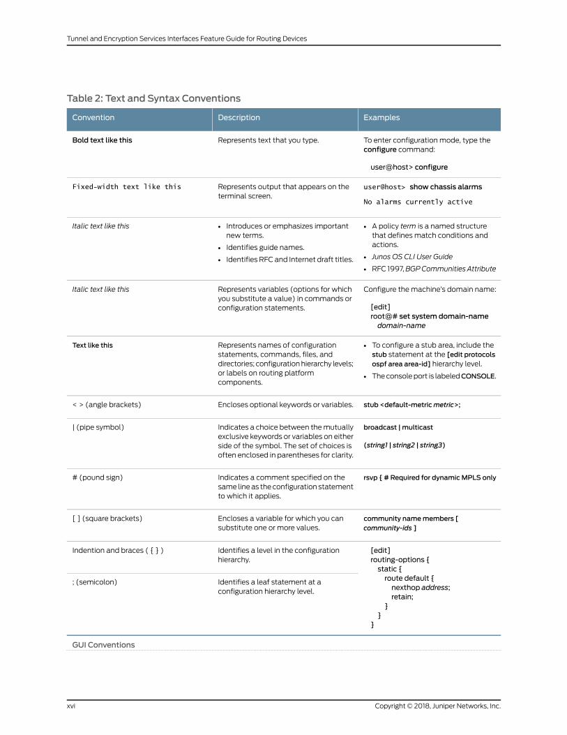
Table 2: Text and Syntax Conventions
ExamplesDescriptionConvention
To enter configuration mode, type theconfigure command:
user@host> configure
Represents text that you type.Bold text like this
user@host> show chassis alarms
No alarms currently active
Represents output that appears on theterminal screen.
Fixed-width text like this
• A policy term is a named structurethat defines match conditions andactions.
• Junos OS CLI User Guide
• RFC 1997,BGPCommunities Attribute
• Introduces or emphasizes importantnew terms.
• Identifies guide names.
• Identifies RFC and Internet draft titles.
Italic text like this
Configure themachine’s domain name:
[edit]root@# set system domain-namedomain-name
Represents variables (options for whichyou substitute a value) in commands orconfiguration statements.
Italic text like this
• To configure a stub area, include thestub statement at the [edit protocolsospf area area-id] hierarchy level.
• Theconsoleport is labeledCONSOLE.
Represents names of configurationstatements, commands, files, anddirectories; configurationhierarchy levels;or labels on routing platformcomponents.
Text like this
stub <default-metricmetric>;Encloses optional keywords or variables.< > (angle brackets)
broadcast | multicast
(string1 | string2 | string3)
Indicates a choice between themutuallyexclusive keywords or variables on eitherside of the symbol. The set of choices isoften enclosed in parentheses for clarity.
| (pipe symbol)
rsvp { # Required for dynamicMPLS onlyIndicates a comment specified on thesame lineas theconfiguration statementto which it applies.
# (pound sign)
community namemembers [community-ids ]
Encloses a variable for which you cansubstitute one or more values.
[ ] (square brackets)
[edit]routing-options {static {route default {nexthop address;retain;
}}
}
Identifies a level in the configurationhierarchy.
Indention and braces ( { } )
Identifies a leaf statement at aconfiguration hierarchy level.
; (semicolon)
GUI Conventions
Copyright © 2018, Juniper Networks, Inc.xvi
Tunnel and Encryption Services Interfaces Feature Guide for Routing Devices
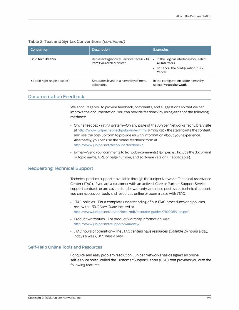
Table 2: Text and Syntax Conventions (continued)
ExamplesDescriptionConvention
• In the Logical Interfaces box, selectAll Interfaces.
• To cancel the configuration, clickCancel.
Representsgraphicaluser interface(GUI)items you click or select.
Bold text like this
In the configuration editor hierarchy,select Protocols>Ospf.
Separates levels in a hierarchy of menuselections.
> (bold right angle bracket)
Documentation Feedback
We encourage you to provide feedback, comments, and suggestions so that we can
improve the documentation. You can provide feedback by using either of the following
methods:
• Online feedback rating system—On any page of the Juniper Networks TechLibrary site
athttp://www.juniper.net/techpubs/index.html, simply click the stars to rate thecontent,
and use the pop-up form to provide us with information about your experience.
Alternately, you can use the online feedback form at
http://www.juniper.net/techpubs/feedback/.
• E-mail—Sendyourcommentsto [email protected]. Includethedocument
or topic name, URL or page number, and software version (if applicable).
Requesting Technical Support
Technical product support is available through the JuniperNetworksTechnicalAssistance
Center (JTAC). If you are a customer with an active J-Care or Partner Support Service
support contract, or are covered under warranty, and need post-sales technical support,
you can access our tools and resources online or open a case with JTAC.
• JTAC policies—For a complete understanding of our JTAC procedures and policies,
review the JTAC User Guide located at
http://www.juniper.net/us/en/local/pdf/resource-guides/7100059-en.pdf.
• Product warranties—For product warranty information, visit
http://www.juniper.net/support/warranty/.
• JTAC hours of operation—The JTAC centers have resources available 24 hours a day,
7 days a week, 365 days a year.
Self-Help Online Tools and Resources
For quick and easy problem resolution, Juniper Networks has designed an online
self-service portal called the Customer Support Center (CSC) that provides youwith the
following features:
xviiCopyright © 2018, Juniper Networks, Inc.
About the Documentation

• Find CSC offerings: http://www.juniper.net/customers/support/
• Search for known bugs: https://prsearch.juniper.net/
• Find product documentation: http://www.juniper.net/documentation/
• Find solutions and answer questions using our Knowledge Base: http://kb.juniper.net/
• Download the latest versions of software and review release notes:
http://www.juniper.net/customers/csc/software/
• Search technical bulletins for relevant hardware and software notifications:
http://kb.juniper.net/InfoCenter/
• Join and participate in the Juniper Networks Community Forum:
http://www.juniper.net/company/communities/
• Open a case online in the CSC Case Management tool: http://www.juniper.net/cm/
Toverify serviceentitlementbyproduct serial number, useourSerialNumberEntitlement
(SNE) Tool: https://entitlementsearch.juniper.net/entitlementsearch/
Opening a Casewith JTAC
You can open a case with JTAC on theWeb or by telephone.
• Use the Case Management tool in the CSC at http://www.juniper.net/cm/.
• Call 1-888-314-JTAC (1-888-314-5822 toll-free in the USA, Canada, and Mexico).
For international or direct-dial options in countries without toll-free numbers, see
http://www.juniper.net/support/requesting-support.html.
Copyright © 2018, Juniper Networks, Inc.xviii
Tunnel and Encryption Services Interfaces Feature Guide for Routing Devices
PART 1
Tunnel Services
• Overview on page 3
• Encapsulating One Protocol Over Another Using GRE Interfaces on page 21
• Encapsulating One IP Packet Over Another Using IP-IP Interfaces on page 27
• Filtering Unicast Packets Through Multicast Tunnel Interfaces on page 29
• Connecting Logical Systems Using Logical Tunnel Interfaces on page 37
• Configuring Layer 2 Ethernet Services over GRE Tunnel Interfaces on page 57
• Understanding Default PIM Tunnel Configurations on page 69
• Facilitating VRF Table Lookup Using Virtual Loopback Tunnel Interfaces on page 71
• Enabling a VPN to Travel Through a Non-MPLS Network Using Dynamic
Tunnels on page 77
1Copyright © 2018, Juniper Networks, Inc.

Copyright © 2018, Juniper Networks, Inc.2
Tunnel and Encryption Services Interfaces Feature Guide for Routing Devices
CHAPTER 1
Overview
• Tunnel Services Overview on page 3
• Tunnel Interface Configuration on MX Series Routers Overview on page 6
• Configuring Tunnel Interfaces on T4000 Routers on page 8
• Configuring Tunnel Interfaces on an MX Series Router with a 16x10GE 3D
MPC on page 9
• Configuring Tunnel Interfaces on MX Series Routers with the MPC3E on page 10
• Example: Configuring Tunnel Interfaces on the MPC3E on page 11
• Configuring Tunnel Interfaces on MX Series Routers with MPC4E on page 13
• Tunnel Interfaces on MX Series Routers with MPC7E-10G, MPC7E-MRATE,
MX2K-MPC8E, and MX2K-MPC9E on page 13
• Configuring Tunnel Interfaces on MX Series Routers with
MPC7E-MRATE/MPC7E-10G on page 15
• Configuring Tunnel Interfaces on MX Series Routers with MX2K-MPC8E on page 16
• Configuring Tunnel Interfaces on MX Series Routers with MX2K-MPC9E on page 17
• Example: Configuring Tunnel Interfaces on a Gigabit Ethernet 40-Port DPC on page 18
• Example:ConfiguringTunnel Interfacesona 10-Gigabit Ethernet4-PortDPConpage 19
Tunnel Services Overview
By encapsulating arbitrary packets inside a transport protocol, tunneling provides a
private, securepath throughanotherwisepublicnetwork.Tunnelsconnectdiscontinuous
subnetworks and enable encryption interfaces, virtual private networks (VPNs), and
MPLS. If you have a Tunnel Physical Interface Card (PIC) installed in your M Series or T
Series router, you can configure unicast, multicast, and logical tunnels.
You can configure two types of tunnels for VPNs: one to facilitate routing table lookups
and another to facilitate VPN routing and forwarding instance (VRF) table lookups.
For information about encryption interfaces, see “Configuring Encryption Interfaces” on
page 83. For information about VPNs, see the Junos OS VPNs Library for Routing Devices.
For information about MPLS, see theMPLS Applications Feature Guide.
3Copyright © 2018, Juniper Networks, Inc.

On SRX Series devices, Generic Routing Encapsulation (GRE) and IP-IP tunnels use
internal interfaces, gr-0/0/0 and ip-0/0/0, respectively. The Junos OS creates these
interfaces at system bootup; they are not associated with physical interfaces.
The Juniper Networks Junos OS supports the tunnel types shown in the following table.
Table 3: Tunnel Interface Types
DescriptionInterface
Configurable generic routing encapsulation (GRE) interface. GRE allows theencapsulation of one routing protocol over another routing protocol.
Within a router, packets are routed to this internal interface, where they are firstencapsulatedwithaGREpacketand then re-encapsulatedwithanotherprotocolpacket to complete the GRE. The GRE interface is an internal interface only andis not associated with a physical interface. Youmust configure the interface forit to perform GRE.
gr-0/0/0
Internally generated GRE interface. This interface is generated by the Junos OSto handle GRE. You cannot configure this interface.
gre
Configurable IP-over-IP encapsulation (also called IP tunneling) interface. IPtunneling allows the encapsulation of one IP packet over another IP packet.
Packets are routed to an internal interface where they are encapsulated withan IP packet and then forwarded to the encapsulating packet's destinationaddress. The IP-IP interface is an internal interface only and is not associatedwith a physical interface. Youmust configure the interface for it to perform IPtunneling.
ip-0/0/0
Internally generated IP-over-IP interface. This interface is generatedby the JunosOS to handle IP-over-IP encapsulation. It is not a configurable interface.
ipip
The lt interfaceonMSeries andTSeries routers supports configurationof logicalsystems—the capability to partition a single physical router intomultiple logicaldevices that perform independent routing tasks.
On SRX Series devices, the lt interface is a configurable logical tunnel interfacethat interconnects logical systems. See the Junos OS Logical SystemsConfiguration Guide for Security Devices.
lt-0/0/0
Internally generatedmulticast tunnel interface.Multicast tunnels filter all unicastpackets; if an incoming packet is not destined for a 224/8-or-greater prefix, thepacket is dropped and a counter is incremented.
Within a router, packets are routed to this internal interface formulticast filtering.Themulticast tunnel interface is an internal interface only and is not associatedwith a physical interface. If your router has a Tunnel Services PIC, the Junos OSautomatically configures onemulticast tunnel interface (mt-) for each virtualprivate network (VPN) you configure. You do not need to configure multicasttunnel interfaces. However, you can configure properties onmt- interfaces, suchas themulticast-only statement.
mt-0/0/0
Internally generatedmulticast tunnel interface. This interface is generated bythe JunosOStohandlemulticast tunnel services. It is notaconfigurable interface.
mtun
Copyright © 2018, Juniper Networks, Inc.4
Tunnel and Encryption Services Interfaces Feature Guide for Routing Devices
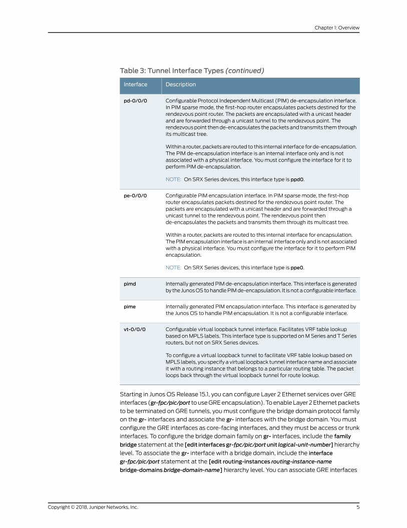
Table 3: Tunnel Interface Types (continued)
DescriptionInterface
Configurable Protocol IndependentMulticast (PIM) de-encapsulation interface.In PIM sparse mode, the first-hop router encapsulates packets destined for therendezvous point router. The packets are encapsulated with a unicast headerand are forwarded through a unicast tunnel to the rendezvous point. Therendezvouspoint thende-encapsulates thepacketsand transmits themthroughits multicast tree.
Within a router, packets are routed to this internal interface for de-encapsulation.The PIM de-encapsulation interface is an internal interface only and is notassociated with a physical interface. Youmust configure the interface for it toperform PIM de-encapsulation.
NOTE: On SRX Series devices, this interface type is ppd0.
pd-0/0/0
Configurable PIM encapsulation interface. In PIM sparse mode, the first-hoprouter encapsulates packets destined for the rendezvous point router. Thepackets are encapsulated with a unicast header and are forwarded through aunicast tunnel to the rendezvous point. The rendezvous point thende-encapsulates the packets and transmits them through its multicast tree.
Within a router, packets are routed to this internal interface for encapsulation.ThePIMencapsulation interface is an internal interfaceonlyand is notassociatedwith a physical interface. Youmust configure the interface for it to perform PIMencapsulation.
NOTE: On SRX Series devices, this interface type is ppe0.
pe-0/0/0
Internally generated PIM de-encapsulation interface. This interface is generatedby the JunosOStohandlePIMde-encapsulation. It is notaconfigurable interface.
pimd
Internally generated PIM encapsulation interface. This interface is generated bythe Junos OS to handle PIM encapsulation. It is not a configurable interface.
pime
Configurable virtual loopback tunnel interface. Facilitates VRF table lookupbased onMPLS labels. This interface type is supported onMSeries and T Seriesrouters, but not on SRX Series devices.
To configure a virtual loopback tunnel to facilitate VRF table lookup based onMPLS labels, you specify a virtual loopback tunnel interfacenameandassociateit with a routing instance that belongs to a particular routing table. The packetloops back through the virtual loopback tunnel for route lookup.
vt-0/0/0
Starting in Junos OS Release 15.1, you can configure Layer 2 Ethernet services over GRE
interfaces (gr-fpc/pic/port touseGREencapsulation). Toenable Layer 2Ethernetpackets
to be terminated on GRE tunnels, youmust configure the bridge domain protocol family
on the gr- interfaces and associate the gr- interfaces with the bridge domain. Youmust
configure the GRE interfaces as core-facing interfaces, and theymust be access or trunk
interfaces. To configure the bridge domain family on gr- interfaces, include the family
bridge statement at the [edit interfacesgr-fpc/pic/portunit logical-unit-number]hierarchy
level. To associate the gr- interface with a bridge domain, include the interface
gr-fpc/pic/port statement at the [edit routing-instances routing-instance-name
bridge-domains bridge-domain-name] hierarchy level. You can associate GRE interfaces
5Copyright © 2018, Juniper Networks, Inc.
Chapter 1: Overview
in a bridge domainwith the corresponding VLAN ID or list of VLAN IDs in a bridge domain
by including the vlan-id (all | none |number) statementor the vlan-id-list [vlan-id-numbers
] statement at the [edit bridge-domains bridge-domain-name] hierarchy level. The VLAN
IDs configured for the bridge domain must match with the VLAN IDs that you configure
for GRE interfaces by using the vlan-id (all | none | number) statement or the vlan-id-list
[ vlan-id-numbers ] statement at the [edit interfaces gr-fpc/pic/port unit
logical-unit-number]hierarchy level. YoucanalsoconfigureGRE interfaceswithinabridge
domain associated with a virtual switch instance. Layer 2 Ethernet packets over GRE
tunnels are also supportedwith the GRE key option. The gre-keymatch condition allows
a user tomatch against the GRE key field, which is an optional field in GRE encapsulated
packets. The key can bematched as a single key value, a range of key values, or both.
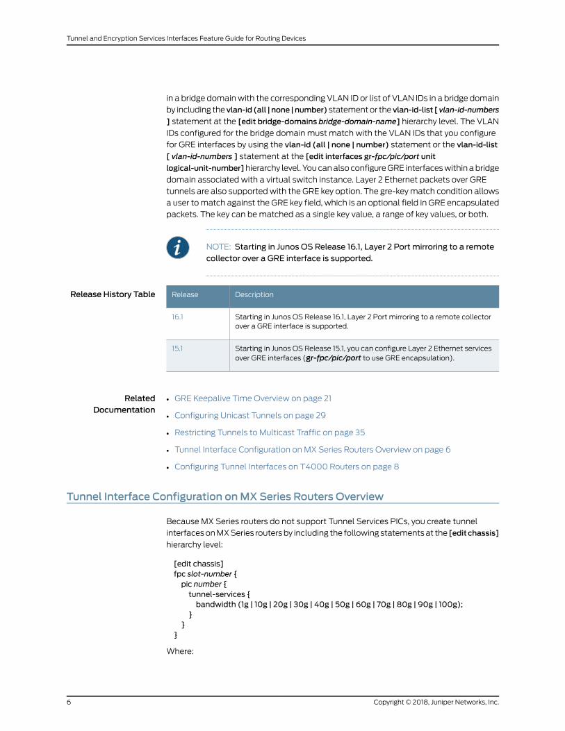
NOTE: Starting in Junos OS Release 16.1, Layer 2 Port mirroring to a remotecollector over a GRE interface is supported.
Release History Table DescriptionRelease
Starting in Junos OS Release 16.1, Layer 2 Port mirroring to a remote collectorover a GRE interface is supported.
16.1
Starting in Junos OS Release 15.1, you can configure Layer 2 Ethernet servicesover GRE interfaces (gr-fpc/pic/port to use GRE encapsulation).
15.1
RelatedDocumentation
GRE Keepalive Time Overview on page 21•
• Configuring Unicast Tunnels on page 29
• Restricting Tunnels to Multicast Traffic on page 35
• Tunnel Interface Configuration on MX Series Routers Overview on page 6
• Configuring Tunnel Interfaces on T4000 Routers on page 8
Tunnel Interface Configuration onMX Series Routers Overview
Because MX Series routers do not support Tunnel Services PICs, you create tunnel
interfacesonMXSeries routersby including the followingstatementsat the [editchassis]
hierarchy level:
[edit chassis]fpc slot-number {pic number {tunnel-services {bandwidth (1g | 10g | 20g | 30g | 40g | 50g | 60g | 70g | 80g | 90g | 100g);
}}
}
Where:
Copyright © 2018, Juniper Networks, Inc.6
Tunnel and Encryption Services Interfaces Feature Guide for Routing Devices

fpc slot-number is the slot number of theDPC,MPC, orMIC. On theMX80 router, possible
values are 0 and 1. On other MX Series routers, if two SCBs are installed, the range is 0
through 11. If three SCBs are installed, the range is 0 through 5 and 7 through 11.
picnumber is the slot number of thePIC.OnMX80 routers, if the FPC is 0, thePIC number
can only be 0. If the FPC is 1, the PIC range is 0 through 3. For all other MX Series routers,
the range is 0 through 3.
bandwidth (1g | 10g | 20g | 30g | 40g | 50g | 60g | 70g | 80g | 90g | 100g) is themaximum
amount of bandwidth, in gigabits, that is available for tunnel traffic on each Packet
Forwarding Engine. For MPCs and MICs, this bandwidth is not reserved for tunnel traffic
and can be shared by the network interfaces. For DPCs, this bandwidth is reserved and
cannot be shared by the network interfaces.
NOTE: When you use MPCs andMICs, tunnel interfaces are soft interfacesandallowasmuchtrafficas the forwarding-pathallows, so it isadvantageousto set up tunnel services without artificially limiting traffic by use of thebandwidth option. However, youmust specify bandwidthwhen configuring
tunnel services forMXSeries routerswith DPCs or FPCs. The GRE key optionis not supported on the tunnel interfaces for DPCs onMX960 routers.
If you specify a bandwidth that is not compatible, tunnel services are not activated. For
example, you cannot specify a bandwidth of 1 Gbps for a Packet Forwarding Engine on
a 10-Gigabit Ethernet 4-port DPC.
When you configure tunnel interfaces on the Packet Forwarding Engine of a 10-Gigabit
Ethernet 4-port DPC, the Ethernet interfaces for that port are removed from service and
are no longer visible in the command-line interface (CLI). The Packet Forwarding Engine
of a 10-Gigabit Ethernet 4-port DPC supports either tunnel interfaces or Ethernet
interfaces, but not both. Each port on the 10-Gigabit Ethernet 4-port DPC includes two
LEDs, one for tunnel services and one for Ethernet services, to indicate which type of
service isbeingused.On theGigabit Ethernet40-portDPC, youcanconfigureboth tunnel
and Ethernet interfaces at the same time.
To verify that the tunnel interfaces have been created, issue the show interfaces terse
operational mode command. For more information, see the CLI Explorer. The bandwidth
that you specify determines the port number of the tunnel interfaces that are created.
When you specify a bandwidth of 1g, the port number is always 10.When you specify any
other bandwidth, the port number is always 0.
NOTE: When the tunnel bandwidth is unspecified in the Routing Engine CLI,themaximum tunnel bandwidth for an MPC3E is 60G.
NOTE: You cannot configure ingress queueing and tunnel services on thesameMPCbecausedoingsocausesPFEforwardingtostop.Youcanconfigureand use each feature separately.
7Copyright © 2018, Juniper Networks, Inc.
Chapter 1: Overview
RelatedDocumentation
Example: Configuring Tunnel Interfaces on a Gigabit Ethernet 40-Port DPC on page 18•
• Example:ConfiguringTunnel Interfacesona 10-Gigabit Ethernet4-PortDPConpage 19
• Example: Configuring Tunnel Interfaces on the MPC3E on page 11
• bandwidth (Tunnel Services)
• tunnel-services (Chassis)
Configuring Tunnel Interfaces on T4000 Routers
To create tunnel interfaces on a T4000 Core Router, include the following statements
at the [edit chassis] hierarchy level:
[edit chassis]fpc slot-number {pic number {tunnel-services {bandwidth bandwidth-value;
}}
}
fpc slot-number denotes the slot number of the FPC. On the T4000 router, the range is
0 through 7.
NOTE:
• This applies only to the T4000 Type 5 FPC. If any other type of FPC isconfigured in this slot, this configuration is ignored and no tunnel physicalinterface is created.
• When you use Type 5 FPCs, the tunnel interfaces are soft interfaces andallowasmuch traffic as the forwarding-path allows. So, it is advantageousto setup tunnel services without artificially limiting traffic by setting thebandwidth statement.
pic number on the T4000 router is 0 or 1.
bandwidth bandwidth-value is the amount of bandwidth to reserve for the tunnel traffic
oneachPacketForwardingEngine.Thebandwidthvalueaccepted includeseverymultiple
of 10g up to 100g.
If you specify a bandwidth that is not compatible, tunnel services are not activated. For
example, you cannot specify a bandwidth of 1 Gbps for a Packet Forwarding Engine on
a 100-Gigabit Ethernet PIC with CFP.
To verify that the tunnel interfaces have been created, issue the show interfaces terse
operational mode command. For more information, see the Junos Interfaces Command
Reference.
Copyright © 2018, Juniper Networks, Inc.8
Tunnel and Encryption Services Interfaces Feature Guide for Routing Devices

RelatedDocumentation
bandwidth (Tunnel Services)•
• tunnel-services (Chassis)
Configuring Tunnel Interfaces on anMX Series Router with a 16x10GE 3DMPC
MX960,MX480,andM240routerssupport the 16-port 10-GigabitEthernetMPC(16x10GE
3DMPC) fixed configuration Field Replaceable Unit (FRU). Each Packet Forwarding
Engineona 16x10GEMPCcansupporta full-duplex 10Gbps tunnelwithout losing line-rate
capacity. Forexample, a full-duplex 10Gbps tunnel canbehostedona 10-Gigabit-Ethernet
port,while twoother 10-Gigabit-Ethernetportson thesamePFEcanconcurrently forward
line-rate traffic.
To configure an MPC and its corresponding Packet Forwarding Engine to use tunneling
services, include the tunnel-services statement at the [edit chassis fpc slot-number pic
pic-number] hierarchy level. The Junos OS creates tunnel interfaces gr-fpc/pic/port.0,
vt-fpc/pic/port.0, and so on. You also configure the amount of bandwidth reserved for
tunnel services.
[edit chassis]fpc slot-number {pic number {tunnel-services {bandwidth 10g;
}}
}
fpc slot-number is the slot number of the MPC. If two SCBs are installed, the range is 0
through 11. If three SCBs are installed, the range is 0 through 5 and 7 through 11.
pic number is the number of the Packet Forwarding Engine on the MPC. The range is 0
through 3.
bandwidth 10g is the amount of bandwidth to reserve for tunnel traffic on each Packet
Forwarding Engine.
In the following example, you create tunnel interfaces on Packet Forwarding Engine 0of MPC 4 with 10 Gbps of bandwidth reserved for tunnel traffic. With this configuration,the tunnel interfaces created are gr-4/0/0, pe-4/0/0, pd-4/0/0, vt-4/0/0, and so on.
[edit chassis]fpc 4 pic 0 {tunnel-services {bandwidth 10g;
}}
RelatedDocumentation
16-Port 10-Gigabit Ethernet MPC on MX Series Routers (16x10GE 3DMPC) Overview•
• Configuring Junos OS to Run a Specific Network Services Mode in MX Series Routers
9Copyright © 2018, Juniper Networks, Inc.
Chapter 1: Overview

Configuring Tunnel Interfaces onMX Series Routers with theMPC3E
Because the MX Series routers do not support Tunnel Services PICs, you create tunnel
interfacesonMXSeries routersby including the followingstatementsat the [editchassis]
hierarchy level:
[edit chassis]fpc slot-number {pic number {tunnel-services {bandwidth (1g | 10g | 20g | 40g);
}}
}
fpc slot-number is the slot number of the DPC, MPC, or MIC. On the MX80 router, the
range is 0 through 1. On other MX series routers, if two SCBs are installed, the range is 0
through 11. If three SCBs are installed, the range is 0 through 5 and 7 through 11.
The picnumberOnMX80 routers, if the FPC is 0, the PIC number can only be0. If the FPC
is 1, the PIC range is 0 through 3. For all other MX series routers, the range is 0 through 3.
bandwidth (1g | 10g | 20g | 40g) is the amount of bandwidth to reserve for tunnel traffic
on each Packet Forwarding Engine.
NOTE: When you use MPCs andMICs, tunnel interfaces are soft interfacesandallowasmuchtrafficas the forwarding-pathallows, so it isadvantageousto setup tunnel services without artificially limiting traffic by use of thebandwidth option. However, youmust specify bandwidthwhen configuring
tunnel services for MX Series routers with DPCs or FPCs.
1g indicates that 1 gigabit per second of bandwidth is reserved for tunnel traffic.
10g indicates that 10 gigabits per second of bandwidth is reserved for tunnel traffic.
20g indicates that 20 gigabits per second of bandwidth is reserved for tunnel traffic.
40g indicates that 40 gigabits per second of bandwidth is reserved for tunnel traffic.
If you specify a bandwidth that is not compatible, tunnel services are not activated. For
example, you cannot specify a bandwidth of 1 Gbps for a Packet Forwarding Engine on
a 10-Gigabit Ethernet 4-port DPC.
To verify that the tunnel interfaces have been created, issue the show interfaces terse
operational mode command. For more information, see the CLI Explorer. The bandwidth
that you specify determines the port number of the tunnel interfaces that are created.
When you specify a bandwidth of 1g, the port number is always 10.When you specify any
other bandwidth, the port number is always 0.
Copyright © 2018, Juniper Networks, Inc.10
Tunnel and Encryption Services Interfaces Feature Guide for Routing Devices
RelatedDocumentation
Example: Configuring Tunnel Interfaces on a Gigabit Ethernet 40-Port DPC on page 18•
• Example:ConfiguringTunnel Interfacesona 10-Gigabit Ethernet4-PortDPConpage 19
• Example: Configuring Tunnel Interfaces on the MPC3E on page 11
• bandwidth (Tunnel Services)
• tunnel-services (Chassis)
• [edit chassis] Hierarchy Level
Example: Configuring Tunnel Interfaces on theMPC3E
• Requirements for Configuration of Tunnel Interfaces on the MPC3E on page 11
• Ethernet Tunnel Configuration Overview on page 11
• Configuring a 20-Gigabit Ethernet Tunnel on page 11
• Configuring a Tunnel With Unspecified Bandwidth on page 12
Requirements for Configuration of Tunnel Interfaces on theMPC3E
This example requires MX Series routers with the MPC3E.
Ethernet Tunnel Configuration Overview
MX Series routers do not support Tunnel Services PICs. However, you can create one set
of tunnel interfacesper pic slot up toamaximumof4 slots from0-3onMXSeries routers
with the MPC3E.
Toconfigure the tunnels, include the tunnel-servicesstatementandanoptionalbandwidth
of (1g | 10g | 20g | 30g | 40g) at the [edit chassis] hierarchy level.
NOTE: Whenno tunnel bandwidth is specified, the tunnel interface canhaveamaximum bandwidth of up to 60Gbps.
NOTE: AMIC need not be plugged in to the MPC3E to configure a tunnelinterface.
Configuring a 20-Gigabit Ethernet Tunnel
Step-by-StepProcedure
In the following example, you create tunnel interfaces on PIC-slot 1 of MPC 0with
20 gigabit per second of bandwidth reserved for tunnel traffic. With this configuration,
the tunnel interfaces created are gr-0/1/0, pe-0/1/0, pd-0/1/0, vt-0/1/0, and so on.
1. To create a 20 gigabit per second tunnel interface, use the following configuration:
[edit chassis]fpc 0 pic 1 {tunnel-services {
11Copyright © 2018, Juniper Networks, Inc.
Chapter 1: Overview
bandwidth 20g;}
}
Configuring a TunnelWith Unspecified Bandwidth
Step-by-StepProcedure
In the following example, you create a tunnel interface on PIC-slot 3 of MPC 0with no
bandwidth specified. The tunnel traffic cancarry up toamaximumof60Gbpsdepending
on other trafiic through the packet forwarding engine.With this configuration, the tunnel
interfaces created are gr-0/3/0, pe-0/3/0, pd-0/3/0, vt-0/3/0, and so on.
1. To create a tunnel interface with no bandwidth specification, use the following
configuration:
[edit chassis]fpc 0 pic 3 {tunnel-services;
}
RelatedDocumentation
Example: Configuring Tunnel Interfaces on a Gigabit Ethernet 40-Port DPC on page 18•
• Example:ConfiguringTunnel Interfacesona 10-Gigabit Ethernet4-PortDPConpage 19
• bandwidth (Tunnel Services)
• tunnel-services (Chassis)
• Tunnel Interface Configuration on MX Series Routers Overview on page 6
Copyright © 2018, Juniper Networks, Inc.12
Tunnel and Encryption Services Interfaces Feature Guide for Routing Devices
Configuring Tunnel Interfaces onMX Series Routers with MPC4E
MX Series routers do not support Tunnel Services PICs. However, you can create a set
of tunnel interfaces per PIC slot up to amaximum of four slots from 0 through 3 on MX
Series routers with MPC4E.
To configure the tunnel interfaces, include the tunnel-services statement andanoptional
bandwidth of (1g | 10g | 20g | 30g | 40g) at the [edit chassis] hierarchy level. When no
tunnel bandwidth is specified, the tunnel interface can have amaximum bandwidth of
up to 60 Gbps.
To verify that the tunnel interfaces have been created, issue the show interfaces terse
operational mode command. For more information, see the CLI Explorer. The bandwidth
that you specify determines the port number of the tunnel interfaces that are created.
When you specify a bandwidth of 1g, the port number is always 10.When you specify any
other bandwidth, the port number is always 0.
In the following example, you create tunnel interfaces on PIC 1 ofMPC4with 40 Gbps of
bandwidth reserved for tunnel traffic. fpc slot-number is the slot number of the MPC. In
this configuration, the tunnel interfaces created are gr-4/1/1, pe-4/1/1, pd-4/1/1, vt-4/1/1,
and so on.
1. To create a 40-Gbps tunnel interface, use the following configuration:
[edit chassis]fpc 4 pic 1 {tunnel-services {bandwidth 40g;
}}
RelatedDocumentation
bandwidth (Tunnel Services)•
• tunnel-services (Chassis)
• Tunnel Interface Configuration on MX Series Routers Overview on page 6
Tunnel Interfaces onMX Series Routers with MPC7E-10G, MPC7E-MRATE,MX2K-MPC8E, andMX2K-MPC9E
MPC7E-10G, MPC7E-MRATE, MX2K-MPC8E, and MX2K-MPC9E support a total of four
inline tunnel interfaces per MPC, one per PIC. You can create a set of tunnel interfaces
per PIC slot up to amaximum of four slots (from 0 through 3) on MX Series routers with
theseMPCs.ThesePICsare referred toaspseudo tunnelPICs.Youcreate tunnel interfaces
onMXSeries routerswithMPC7E-10G,MPC7E-MRATE,MX2K-MPC8E,andMX2K-MPC9E
by including the following statements at the [edit chassis] hierarchy level:
[edit chassis]fpc slot-number {pic number {tunnel-services {
13Copyright © 2018, Juniper Networks, Inc.
Chapter 1: Overview

bandwidth ;}
}}
Packet Forwarding EngineMapping and Tunnel Bandwidth for MPC7E-MRATE
The tunnel bandwidth for MPC7E-MRATE is 1–120Gbps with an increment of 1Gbps.
However, if you do not specify the bandwidth in the configuration, it is set to 120Gbps.
Table 4 on page 14 shows themapping between the tunnel bandwidth and the Packet
Forwarding Engines for MPC7-MRATE .
Table 4: Packet Forwarding EngineMapping and Tunnel Bandwidth for MPC7E-MRATE
MaximumPFEBandwidth
Maximum TunnelBandwidth per PFEPFEMapping
MaximumBandwidth perTunnel PICPseudo Tunnel PIC
240Gbps120GbpsPFE0120GbpsPIC0
120GbpsPIC1
240Gbps120GbpsPFE1120GbpsPIC2
120GbpsPIC3
Packet Forwarding EngineMapping and Tunnel Bandwidth for MPC7E-10G
The tunnel bandwidth forMPC7E-10G is 1–120Gbpswith an incrementof 1GbpsHowever,
if you do not specify the bandwidth in the configuration, it is set to 120Gbps.
Table 5 on page 14 shows themapping between the tunnel bandwidth and the Packet
Forwarding Engines for MPC7E-10G.
Table 5: Packet Forwarding EngineMapping and Tunnel Bandwidth for MPC7E-10G
MaximumPFEBandwidth
Maximum TunnelBandwidth per PFEPFEMapping
MaximumBandwidth perTunnel PICPseudo Tunnel PIC
200Gbps120GbpsPFE0120GbpsPIC0
120GbpsPIC1
200Gbps120GbpsPFE1120GbpsPIC2
120GbpsPIC3
Packet Forwarding EngineMapping and Tunnel Bandwidth for MX2K-MPC8E
The tunnel bandwidth for MX2K-MPC8E is 1– 120Gbps with an increment of 1Gbps.
However, if you do not specify the bandwidth in the configuration, it is set to 120Gbps.
Copyright © 2018, Juniper Networks, Inc.14
Tunnel and Encryption Services Interfaces Feature Guide for Routing Devices
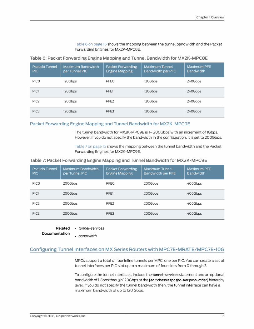
Table 6 on page 15 shows themapping between the tunnel bandwidth and the Packet
Forwarding Engines for MX2K-MPC8E.
Table 6: Packet Forwarding EngineMapping and Tunnel Bandwidth for MX2K-MPC8E
MaximumPFEBandwidth
Maximum TunnelBandwidth per PFE
Packet ForwardingEngine Mapping
MaximumBandwidthper Tunnel PIC
Pseudo TunnelPIC
240Gbps120GbpsPFE0120GbpsPIC0
240Gbps120GbpsPFE1120GbpsPIC1
240Gbps120GbpsPFE2120GbpsPIC2
240Gbps120GbpsPFE3120GbpsPIC3
Packet Forwarding EngineMapping and Tunnel Bandwidth for MX2K-MPC9E
The tunnel bandwidth for MX2K-MPC9E is 1– 200Gbps with an increment of 1Gbps.
However, if you do not specify the bandwidth in the configuration, it is set to 200Gbps.
Table 7 on page 15 shows themapping between the tunnel bandwidth and the Packet
Forwarding Engines for MX2K-MPC9E.
Table 7: Packet Forwarding EngineMapping and Tunnel Bandwidth for MX2K-MPC9E
MaximumPFEBandwidth
Maximum TunnelBandwidth per PFE
Packet ForwardingEngine Mapping
MaximumBandwidthper Tunnel PIC
Pseudo TunnelPIC
400Gbps200GbpsPFE0200GbpsPIC0
400Gbps200GbpsPFE1200GbpsPIC1
400Gbps200GbpsPFE2200GbpsPIC2
400Gbps200GbpsPFE3200GbpsPIC3
RelatedDocumentation
tunnel-services•
• bandwidth
Configuring Tunnel Interfaces onMXSeries RouterswithMPC7E-MRATE/MPC7E-10G
MPCs support a total of four inline tunnels per MPC, one per PIC. You can create a set of
tunnel interfaces per PIC slot up to amaximum of four slots from 0 through 3
To configure the tunnel interfaces, include the tunnel-services statement andanoptional
bandwidthof 1Gbps through 120Gbpsat the [editchassis fpc fpc-slotpicnumber]hierarchy
level. If you do not specify the tunnel bandwidth then, the tunnel interface can have a
maximum bandwidth of up to 120 Gbps.
15Copyright © 2018, Juniper Networks, Inc.
Chapter 1: Overview
[edit chassis]fpc slot-number {pic number {tunnel-services {bandwidth ;
}}
}
To verify that the tunnel interfaces have been created, issue the show interfaces terse
operational mode command. For more information, see the CLI Explorer.
In the following example, you create tunnel interfaces on PIC 1 of MPC 5 with 40 Gbps
of bandwidth reserved for tunnel traffic. fpc slot-number is the slot number of the MPC.
In this configuration, the tunnel interfacescreatedaregr-5/1/1, pe-5/1/1, pd-5/1/1, vt-5/1/1,
and so on.
To create a 40-Gbps tunnel interface, use the following configuration:
[edit chassis]fpc 5 {pic 1 {tunnel-services {bandwidth 40g;
}}}
RelatedDocumentation
Tunnel Interfaces on MX Series Routers with MPC7E-10G, MPC7E-MRATE,
MX2K-MPC8E, and MX2K-MPC9E on page 13
•
• Configuring Tunnel Interfaces on MX Series Routers with MX2K-MPC8E on page 16
• Configuring Tunnel Interfaces on MX Series Routers with MX2K-MPC9E on page 17
Configuring Tunnel Interfaces onMX Series Routers with MX2K-MPC8E
MX2K-MPC8E support a total of four inline tunnels perMPC, one per PIC. You can create
a set of tunnel interfaces per PIC slot up to amaximum of four slots from 0 through 3.
To configure the tunnel interfaces, include the tunnel-services statement andanoptional
bandwidth of 1–120Gbps at the [edit chassis fpc fpc-slot pic number ] hierarchy level. If
you do not specify the tunnel bandwidth then, the tunnel interface can have amaximum
bandwidth of up to 120 Gbps.
[edit chassis]fpc slot-number {pic number {tunnel-services {bandwidth;
}}
}
Copyright © 2018, Juniper Networks, Inc.16
Tunnel and Encryption Services Interfaces Feature Guide for Routing Devices
To verify that the tunnel interfaces have been created, issue the show interfaces terse
operational mode command. For more information, see the CLI Explorer.
In the following example, you create tunnel interfaces on PIC 1 of MPC 5 with 40 Gbpsof bandwidth reserved for tunnel traffic. fpc slot-number is the slot number of the MPC.In this configuration, the tunnel interfacescreatedaregr-5/1/1, pe-5/1/1, pd-5/1/1, vt-5/1/1,and so on.
To create a 40-Gbps tunnel interface, use the following configuration:
[edit chassis]fpc 5 {pic 1 {tunnel-services {bandwidth 40g;
}}}
RelatedDocumentation
Tunnel Interfaces on MX Series Routers with MPC7E-10G, MPC7E-MRATE,
MX2K-MPC8E, and MX2K-MPC9E on page 13
•
• Configuring Tunnel Interfaces on MX Series Routers with MPC7E-MRATE/MPC7E-10G
on page 15
• Configuring Tunnel Interfaces on MX Series Routers with MX2K-MPC9E on page 17
Configuring Tunnel Interfaces onMX Series Routers with MX2K-MPC9E
MX2K-MPC9Esupports a total of four inline tunnels perMPC, oneperPIC. Youcancreate
a set of tunnel interfaces per PIC slot up to amaximum of four slots from 0 through 3.
To configure the tunnel interfaces, include the tunnel-services statement andanoptional
bandwidth in the range 1–200Gbps at the [edit chassis fpc fpc-slotpicnumber ] hierarchy
level. If you do not specify the tunnel bandwidth then, the tunnel interface can have a
maximum bandwidth of up to 200 Gbps.
[edit chassis]fpc slot-number {pic number {tunnel-services {bandwidth ;
}}
}
To verify that the tunnel interfaces have been created, issue the show interfaces terse
operational mode command. For more information, see the CLI Explorer.
17Copyright © 2018, Juniper Networks, Inc.
Chapter 1: Overview
In the following example, you create tunnel interfaces on PIC 1 of MPC 5 with 40 Gbpsof bandwidth reserved for tunnel traffic. fpc slot-number is the slot number of the MPC.In this configuration, the tunnel interfacescreatedaregr-5/1/1, pe-5/1/1, pd-5/1/1, vt-5/1/1,and so on.
To create a 40-Gbps tunnel interface, use the following configuration:
[edit chassis]fpc 5 {pic 1 {tunnel-services {bandwidth 40g;
}}}
RelatedDocumentation
Tunnel Interfaces on MX Series Routers with MPC7E-10G, MPC7E-MRATE,
MX2K-MPC8E, and MX2K-MPC9E on page 13
•
• Configuring Tunnel Interfaces on MX Series Routers with MPC7E-MRATE/MPC7E-10G
on page 15
• Configuring Tunnel Interfaces on MX Series Routers with MX2K-MPC8E on page 16
Example: Configuring Tunnel Interfaces on a Gigabit Ethernet 40-Port DPC
The following example shows how to create tunnel interfaces on Packet ForwardingEngine 1 of DPC 4 with 1 Gbps of bandwidth reserved for tunnel services. On a GigabitEthernet 40-port DPC, tunnel interfaces coexist with Ethernet interfaces. With thisconfiguration, the Gigabit Ethernet interfaces are ge-4/1/0 through ge-4/1/9. The tunnelinterfaces created are gr-4/1/10, pe-4/1/10, pd-4/1/10, vt-4/1/10 and so on.
[edit chassis]fpc 4 pic 1 {tunnel-services {bandwidth 1g;
}}
RelatedDocumentation
Configuring the Junos OS to Support ILMI for Cell Relay Encapsulation on an ATM2 IQ
PIC
•
• Example:ConfiguringTunnel Interfacesona 10-Gigabit Ethernet4-PortDPConpage 19
• Example: Configuring Tunnel Interfaces on the MPC3E on page 11
• bandwidth (Tunnel Services)
• tunnel-services (Chassis)
Copyright © 2018, Juniper Networks, Inc.18
Tunnel and Encryption Services Interfaces Feature Guide for Routing Devices

Example: Configuring Tunnel Interfaces on a 10-Gigabit Ethernet 4-Port DPC
In this example, you create tunnel interfaces on Packet Forwarding Engine 0 of DPC 4with 10 Gbps of bandwidth reserved for tunnel traffic. Ethernet and tunnel interfacescannot coexist on the same Packet Forwarding Engine of a 10-Gigabit Ethernet 4-portDPC. With this configuration, the tunnel interfaces created are gr-4/0/0, pe-4/0/0,pd-4/0/0, vt-4/0/0 and so on.
[edit chassis]fpc 4 pic 0 {tunnel-services {bandwidth 10g;
}}
RelatedDocumentation
• Example: Configuring Tunnel Interfaces on a Gigabit Ethernet 40-Port DPC on page 18
• Example: Configuring Tunnel Interfaces on the MPC3E on page 11
• bandwidth (Tunnel Services)
• tunnel-services (Chassis)
19Copyright © 2018, Juniper Networks, Inc.
Chapter 1: Overview

Copyright © 2018, Juniper Networks, Inc.20
Tunnel and Encryption Services Interfaces Feature Guide for Routing Devices
CHAPTER 2
EncapsulatingOneProtocolOverAnotherUsing GRE Interfaces
• GRE Keepalive Time Overview on page 21
• Configuring GRE Keepalive Time on page 22
• Enabling Fragmentation on GRE Tunnels on page 25
GRE Keepalive TimeOverview
Generic routing encapsulation (GRE) tunnel interfaces do not have a built-inmechanism
for detecting when a tunnel is down. You can enable keepalivemessages to serve as the
detection mechanism.
When you enable aGRE tunnel interface for keepalivemessages, the interface sends out
keepalive request packets to the remote endpoint at regular intervals. If the data path
forwarding for the GRE tunnel works correctly at all points, keepalive response packets
are returned to the originator. These keepalive messages are processed by the Routing
Engine.
You can configure keepalive messages on the physical or logical GRE tunnel interface.
If configuredon thephysical interface, keepalivemessagesare sentonall logical interfaces
that are part of the physical interface. If configured on an individual logical interface,
keepalives are sent only on that logical interface.
You configure how often keepalive messages are sent and the length of time that the
interfacewaits for a keepalive responsebeforemarking the tunnel asoperationally down.
The keepalive request packet is shown in Figure 1 on page 21.
Figure 1: Keepalive Request Packet
g043
514
Outer GRE header Inner GRE header Keepalive payload
The keepalive payload includes information to ensure the keepalive response is correctly
delivered to the application responsible for the GRE keepalive process.
The outer GRE header includes:
• Source IP Address—IP address of the endpoint that initiates the keepalive request
21Copyright © 2018, Juniper Networks, Inc.

• Destination IPAddress—IP address of the endpoint that receives the keepalive request
• GRE Protocol ID—IP
The inner GRE header includes:
• Source IP Address—IP address of the endpoint that receives the keepalive request
• Destination IP Address—IP address of the endpoint that initiates the keepalive request
• GRE Protocol ID—A value that the packet forwarding engine recognizes as a GRE
keepalive packet
NOTE: Starting in Junos OS Release 17.3R1, you can configure IPv6 genericrouting encapsulation (GRE) tunnel interfacesonMXSeries routers. This letsyou run aGRE tunnel over an IPv6 network. Packet payload families that canbe encapsulated within the IPv6 GRE tunnels include IPv4, IPv6, MPLS, andISO. Fragmentation and reassembly of the IPv6 delivery packets is notsupported.
To configure an IPv6 GRE tunnel interface, specify IPv6 addresses for source
and destination at the [interfaces gr-0/0/0 unit 0 tunnel] hierarchy level.
Keepalive is not supported for GRE IPv6.
RelatedDocumentation
Configuring GRE Keepalive Time on page 22•
• keepalive-time on page 116
• hold-time on page 114
Configuring GRE Keepalive Time
• Configuring Keepalive Time and Hold time for a GRE Tunnel Interface on page 23
• Display GRE Keepalive Time Configuration on page 24
• Display Keepalive Time Information on a GRE Tunnel Interface on page 24
Copyright © 2018, Juniper Networks, Inc.22
Tunnel and Encryption Services Interfaces Feature Guide for Routing Devices
Configuring Keepalive Time and Hold time for a GRE Tunnel Interface
Youcanconfigure thekeepalivesonageneric routingencapsulation(GRE) tunnel interface
by including both the keepalive-time statement and the hold-time statement at the [edit
protocols oam gre-tunnel interface interface-name] hierarchy level.
NOTE: For proper operation of keepalives on a GRE interface, youmust alsoinclude the family inet statement at the [edit interfaces interface-name unit
unit] hierarchy level. If you do not include this statement, the interface is
marked as down.
To configure a GRE tunnel interface:
1. Configure theGRE tunnel interfaceat [edit interfaces interface-nameunitunit-number]
hierarchy level, where the interface name is gr-x/y/z, and the family is set as inet.
user@host# set interfaces interface-name unit unit-number family family-name
2. Configure the rest of the GRE tunnel interface options as explained in Configuring a
GRETunnel InterfaceBetweenaPEandCERouterorConfiguring aGRETunnel Interface
Between PE Routers based on requirement.
To configure keepalive time for a GRE tunnel interface:
1. Configure the Operation, Administration, and Maintenance (OAM) protocol at the
[edit protocols] hierarchy level for the GRE tunnel interface.
[edit]user@host# edit protocols oam
2. Configure the GRE tunnel interface option for OAM protocol.
[edit protocols oam]user@host# edit gre-tunnel interface interface-name
3. Configure the keepalive time from 1 through 50 seconds for the GRE tunnel interface.
[edit protocols oam gre-tunnel interface interface-name]user@host# set keepalive-time seconds
4. Configure the hold time from 5 through 250 seconds. Note that the hold timemust
be at least twice the keepalive time.
[edit protocols oam gre-tunnel interface interface-name]user@host# set hold-time seconds
23Copyright © 2018, Juniper Networks, Inc.
Chapter 2: Encapsulating One Protocol Over Another Using GRE Interfaces

Display GRE Keepalive Time Configuration
Purpose Display the configured keepalive time value as 10 and hold time value as 30 on a GRE
tunnel interface (for example, gr-1/1/10.1).
Action Todisplay theconfiguredvalueson theGREtunnel interface, run the showoamgre-tunnel
command at the [edit protocols] hierarchy level:
[edit protocols]user@host# show oam gre-tunnelinterface gr-1/1/10.1 {keepalive-time 10;hold-time 30;
}
Display Keepalive Time Information on a GRE Tunnel Interface
Purpose Display the current status information of a GRE tunnel interface when keepalive time
and hold time parameters are configured on it and when the hold time expires.
Action To verify the current status information on a GRE tunnel interface (for example,
gr-3/3/0.3), run the show interfaces gr-3/3/0.3 terse and show interfaces gr-3/3/0.3
extensive operational commands.
show interfaces gr-3/3/0.3 terse
user@host> show interfaces gr-3/3/0.3 terse
Interface Admin Link Proto Local Remotegr-3/3/0.3 up up inet 192.0.2.1/24 mpls
show interfaces gr-3/3/0.3 extensive
user@host> show interfaces gr-3/3/0.3 extensiveLogical interface gr-3/3/0.3 (Index 73) (SNMP ifIndex 594) (Generation 900) Flags: Point-To-Point SNMP-Traps 0x4000 IP-Header 10.1.19.11:10.1.19.12:47:df:64:0000000000000000 Encapsulation: GRE-NULL Gre keepalives configured: On, Gre keepalives adjacency state: down^^^^^^^^^^^^^^^^^^^^^^^^^^^^^^^^^^^^^^^^^^^^^^^^^^^^^^^^^^^^^^^^^^^^^^^^ Traffic statistics: Input bytes : 15629992 Output bytes : 15912273 Input packets: 243813 Output packets: 179476 Local statistics: Input bytes : 15322586 Output bytes : 15621359 Input packets: 238890 Output packets: 174767 Transit statistics: Input bytes : 307406 0 bps Output bytes : 290914 0 bps Input packets: 4923 0 pps
Copyright © 2018, Juniper Networks, Inc.24
Tunnel and Encryption Services Interfaces Feature Guide for Routing Devices

Output packets: 4709 0 pps Protocol inet, MTU: 1476, Generation: 1564, Route table: 0 Flags: Sendbcast-pkt-to-re Addresses, Flags: Dest-route-down Is-Preferred Is-Primary^^^^^^^^^^^^^^^^^^^^^^^^^^^^^^^^^^^^^^^^ Destination: 192.0.2/24, Local: 192.0.2.1, Broadcast: 192.0.2.255, Generation: 1366 Protocol mpls, MTU: 1464, Maximum labels: 3, Generation: 1565, Route table: 0
NOTE:
When the hold time expires:
• The GRE tunnel will stay up even though the interface cannot send orreceive traffic.
• The Link status will be Up and the Gre keepalives adjacency statewill be
Down.
Meaning The current status information of a GRE tunnel interface with keepalive time and hold
time parameters is displayed as expected when the hold time expires.
RelatedDocumentation
GRE Keepalive Time Overview on page 21•
• keepalive-time on page 116
• hold-time on page 114
Enabling Fragmentation on GRE Tunnels
Toenable fragmentation of IPv4packets in generic routing encapsulation (GRE) tunnels,
include the clear-dont-fragment-bit statement andamaximumtransmission unit (MTU)
setting for the tunnel as part of an existing GRE configuration at the [edit interfaces]
hierarchy level:
[edit interfaces]gr-fpc/pic/port {unit logical-unit-number {clear-dont-fragment-bit;...family inet {mtu 1000;...
}}
}
This statement clears the Don’t Fragment (DF) bit in the packet header, regardless of
thepacket size. If thepacket sizeexceeds the tunnelMTUvalue, thepacket is fragmented
25Copyright © 2018, Juniper Networks, Inc.
Chapter 2: Encapsulating One Protocol Over Another Using GRE Interfaces
before encapsulation. ThemaximumMTU size configurable on the AS or Multiservices
PIC is 9192 bytes.
NOTE: Theclear-dont-fragment-bitstatement is supportedonlyonMXSeries
routers and all M Series routers except the M320 router.
Fragmentation is enabled only on IPv4 packets being encapsulated in IPv4-based GRE
tunnels.
NOTE: This configuration is supported only on GRE tunnels on AS orMultiservices interfaces. If youcommitgre-fragmentationas theencapsulation
type on a standard Tunnel PIC interface, the following console logmessageappears when the PIC comes online:
gr-fpc/pic/port: does not support this encapsulation
The Packet Forwarding Engine updates the IP identification field in the outerIP header of GRE-encapsulated packets, so that reassembly of the packetsis possible after fragmentation. The previous CLI constraint check thatrequired you to configure either the clear-dont-fragment-bit statement or a
tunnel key with the allow-fragmentation statement is no longer enforced.
When you configure the clear-dont-fragment-bit statement on an interface
with theMPLSprotocol family enabled, youmust specify anMTUvalue. ThisMTU valuemust not be greater thanmaximum supported value (9192).
RelatedDocumentation
• Configuring Unicast Tunnels on page 29
Copyright © 2018, Juniper Networks, Inc.26
Tunnel and Encryption Services Interfaces Feature Guide for Routing Devices

CHAPTER 3
Encapsulating One IP Packet OverAnother Using IP-IP Interfaces
• Configuring IPv6-over-IPv4 Tunnels on page 27
• Example: Configuring an IPv6-over-IPv4 Tunnel on page 27
Configuring IPv6-over-IPv4 Tunnels
If you have a Tunnel PIC installed in your M Series or T Series router, you can configure
IPv6-over-IPv4 tunnels. To define a tunnel, you configure a unicast tunnel across an
existing IPv4network infrastructure. IPv6/IPv4packets are encapsulated in IPv4headers
and sent across the IPv4 infrastructure through the configured tunnel. Youmanually
configure configured tunnels on each end point.
On SRX Series devices, Generic Routing Encapsulation (GRE) and IP-IP tunnels use
internal interfaces, gr-0/0/0 and ip-0/0/0, respectively. The Junos OS creates these
interfaces at system bootup; they are not associated with a physical interface.
IPv6-over-IPv4 tunnels are defined in RFC 2893, Transition Mechanisms for IPv6 Hosts
andRouters. For information about configuring a unicast tunnel, see “ConfiguringUnicast
Tunnels” onpage 29. For an IPv6-over-IPv4 tunnel configuration example, see “Example:
Configuring an IPv6-over-IPv4 Tunnel” on page 27.
RelatedDocumentation
Tunnel Services Overview on page 3•
• Example: Configuring an IPv6-over-IPv4 Tunnel on page 27
Example: Configuring an IPv6-over-IPv4 Tunnel
Configure a tunnel on both sides of the connection.
Configuration onRouter 1
[edit]interfaces {gr-1/0/0 {unit 0 {tunnel {source 10.19.2.1;destination 10.19.3.1;
}
27Copyright © 2018, Juniper Networks, Inc.
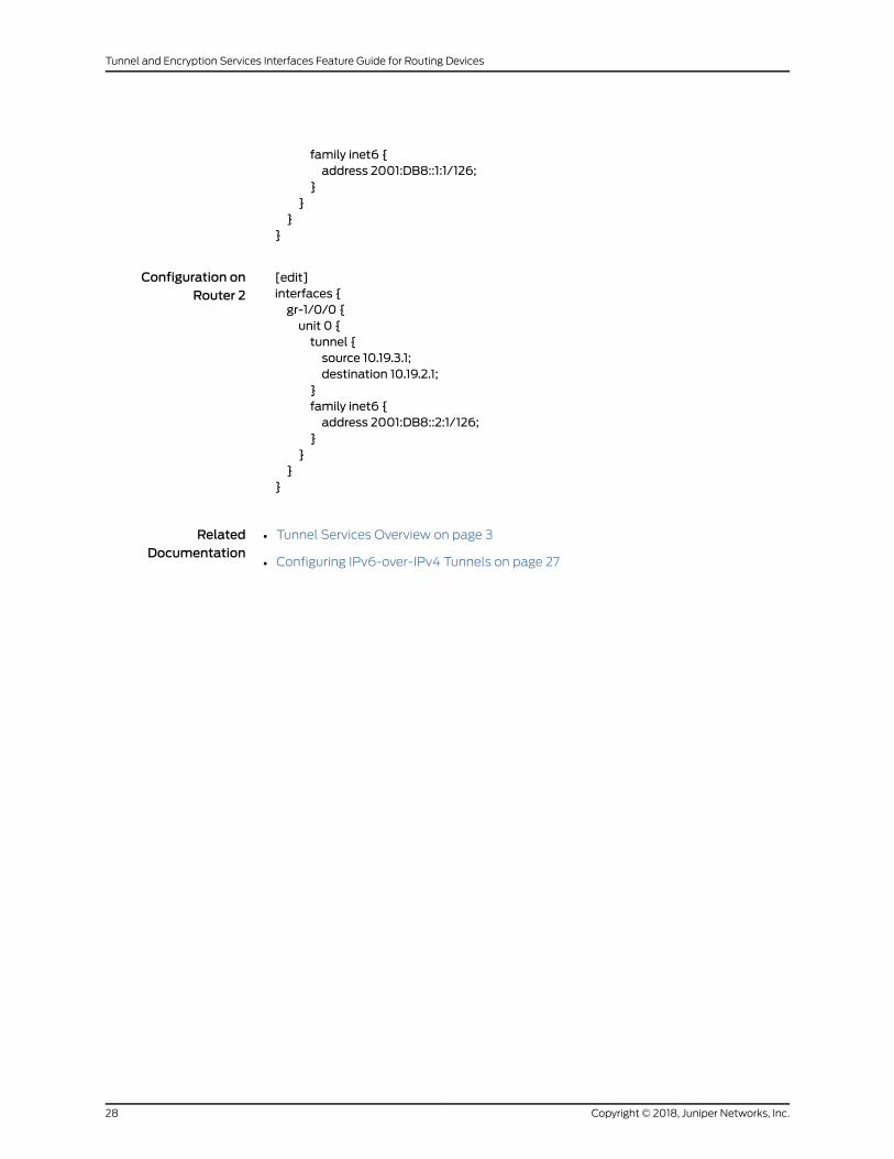
family inet6 {address 2001:DB8::1:1/126;
}}
}}
Configuration onRouter 2
[edit]interfaces {gr-1/0/0 {unit 0 {tunnel {source 10.19.3.1;destination 10.19.2.1;
}family inet6 {address 2001:DB8::2:1/126;
}}
}}
RelatedDocumentation
• Tunnel Services Overview on page 3
• Configuring IPv6-over-IPv4 Tunnels on page 27
Copyright © 2018, Juniper Networks, Inc.28
Tunnel and Encryption Services Interfaces Feature Guide for Routing Devices
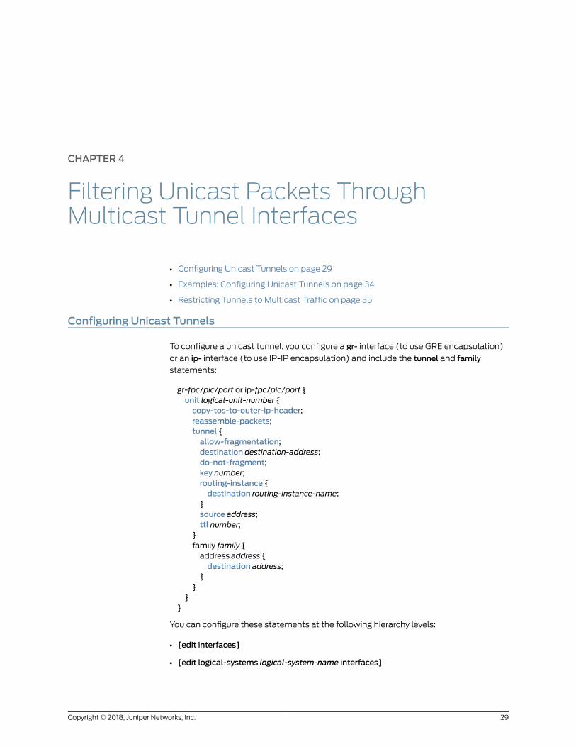
CHAPTER 4
Filtering Unicast Packets ThroughMulticast Tunnel Interfaces
• Configuring Unicast Tunnels on page 29
• Examples: Configuring Unicast Tunnels on page 34
• Restricting Tunnels to Multicast Traffic on page 35
Configuring Unicast Tunnels
To configure a unicast tunnel, you configure a gr- interface (to use GRE encapsulation)
or an ip- interface (to use IP-IP encapsulation) and include the tunnel and family
statements:
gr-fpc/pic/port or ip-fpc/pic/port {unit logical-unit-number {copy-tos-to-outer-ip-header;reassemble-packets;tunnel {allow-fragmentation;destination destination-address;do-not-fragment;key number;routing-instance {destination routing-instance-name;
}source address;ttl number;
}family family {address address {destination address;
}}
}}
You can configure these statements at the following hierarchy levels:
• [edit interfaces]
• [edit logical-systems logical-system-name interfaces]
29Copyright © 2018, Juniper Networks, Inc.

You can configure multiple logical units for each GRE or IP-IP interface, and you can
configure only one tunnel per unit.
NOTE: OnMSeries and T Series routers, you can configure the interface ona service PIC or a tunnel PIC. OnMX Series routers, configure the interfaceon aMultiservices DPC.
Each tunnel interface must be a point-to-point interface. Point to point is the default
interface connection type, so you do not need to include the point-to-point statement in
the logical interface configuration.
Youmust specify the tunnel’s destination and source addresses. The remaining
statements are optional.
NOTE: For transit packets exiting the tunnel, forwarding path features, suchas reverse path forwarding (RPF), forwarding table filtering, source classusage, destination class usage, and stateless firewall filtering, are notsupportedonthe interfacesyouconfigureas tunnelsources,butaresupportedon tunnel-pic interfaces.
However, class-of-service (CoS) information obtained from theGRE or IP-IPheader is carried over the tunnel and is used by the re-entering packets. Formore information, see the Class of Service Feature Guide for Routing Devicesand EX9200 Switches.
Topreventan invalidconfiguration, the JunosOSdisallowssetting theaddressspecified by the source or destination statement at the [edit interfaces
gr-fpc/pic/port unit logical-unit-number tunnel] hierarchy level to be the same
as the interface’s own subnet address, specified by the address statement
at the [edit interfaces gr-fpc/pic/port unit logical-unit-number family
family-name] hierarchy level.
To set the time-to-live (TTL) field that is included in the encapsulating header, include
the ttl statement. If you explicitly configure aTTL value for the tunnel, youmust configure
it to be one larger than the number of hops in the tunnel. For example, if the tunnel has
seven hops, youmust configure a TTL value of 8.
Youmust configure at least one family on the logical interface. To enable MPLS over
GRE tunnel interfaces, youmust include the family mpls statement in the GRE interface
configuration. In addition, youmust include the appropriate statements at the [edit
protocols] hierarchy level to enable Resource Reservation Protocol (RSVP), MPLS, and
label-switched paths (LSPs) over GRE tunnels. Unicast tunnels are bidirectional.
A configured tunnel cannot go through Network Address Translation (NAT) at any point
along the way to the destination. For more information, see “Examples: Configuring
Unicast Tunnels” on page 34 and theMPLS Applications Feature Guide.
Copyright © 2018, Juniper Networks, Inc.30
Tunnel and Encryption Services Interfaces Feature Guide for Routing Devices
For a GRE tunnel, the default is to set the ToS bits in the outer IP header to all zeros. To
have the Routing Engine copy the ToS bits from the inner IP header to the outer, include
the copy-tos-bits-to-outer-ip-header statement. (This inner-to-outer ToS bits copying is
already the default behavior for IP-IP tunnels.)
For GRE tunnel interfaces on Adaptive Services or Multiservices interfaces, you can
configure additional tunnel attributes, as described in the following sections:
• Configuring a Key Number on GRE Tunnels on page 31
• EnablingPacketFragmentationonGRETunnelsPrior toGREEncapsulationonpage32
• Specifying an MTU Setting for the Tunnel on page 32
• Configuring a GRE Tunnel to Copy ToS Bits to the Outer IP Header on page 33
• Enabling Fragmentation and Reassembly on Packets After
GRE-Encapsulation on page 33
• Support for IPv6 GRE tunnels on page 34
Configuring a Key Number on GRE Tunnels
For Adaptive Services and Multiservices interfaces on M Series and T Series routers, you
can assign a key value to identify an individual traffic flowwithin aGRE tunnel, as defined
in RFC 2890, Key and Sequence Number Extensions to GRE. However, only one key is
allowed for each tunnel source and destination pair.
Each IP version 4 (IPv4) packet entering the tunnel is encapsulated with the GRE tunnel
key value. Each IPv4 packet exiting the tunnel is verified by the GRE tunnel key value and
de-encapsulated. The Adaptive Services or Multiservices PIC drops packets that do not
match the configured key value.
To assign a key value to a GRE tunnel interface, include the key statement:
key number;
You can include this statement at the following hierarchy levels:
• [edit interfaces interface-name unit logical-unit-number tunnel]
• [edit logical-systems logical-system-name interfaces interface-name unit
logical-unit-number tunnel]
The key number can be 0 through 4,294,967,295. Youmust configure the same GRE
tunnel key value on tunnel endpoints.
The following example illustrates the use of the key statement in a GRE tunnel
configuration:
interfaces {gr-1/2/0 {unit 0 {tunnel {source 10.58.255.193;destination 10.58.255.195;key 1234;
31Copyright © 2018, Juniper Networks, Inc.
Chapter 4: Filtering Unicast Packets Through Multicast Tunnel Interfaces
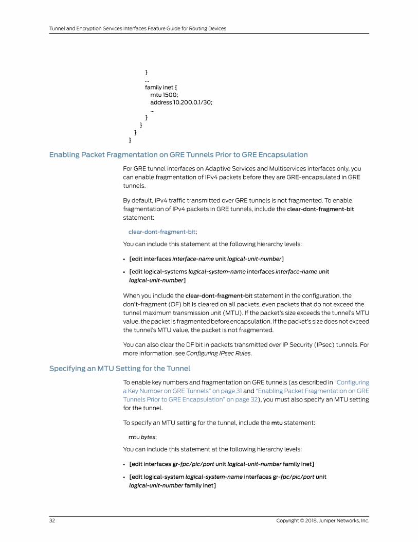
}...family inet {mtu 1500;address 10.200.0.1/30;...
}}
}}
Enabling Packet Fragmentation on GRE Tunnels Prior to GRE Encapsulation
For GRE tunnel interfaces on Adaptive Services and Multiservices interfaces only, you
can enable fragmentation of IPv4 packets before they are GRE-encapsulated in GRE
tunnels.
By default, IPv4 traffic transmitted over GRE tunnels is not fragmented. To enable
fragmentation of IPv4 packets in GRE tunnels, include the clear-dont-fragment-bit
statement:
clear-dont-fragment-bit;
You can include this statement at the following hierarchy levels:
• [edit interfaces interface-name unit logical-unit-number]
• [edit logical-systems logical-system-name interfaces interface-name unit
logical-unit-number]
When you include the clear-dont-fragment-bit statement in the configuration, the
don’t-fragment (DF) bit is cleared on all packets, even packets that do not exceed the
tunnelmaximum transmission unit (MTU). If the packet’s size exceeds the tunnel’s MTU
value, thepacket is fragmentedbeforeencapsulation. If thepacket’s sizedoesnotexceed
the tunnel’s MTU value, the packet is not fragmented.
You can also clear the DF bit in packets transmitted over IP Security (IPsec) tunnels. For
more information, see Configuring IPsec Rules.
Specifying anMTU Setting for the Tunnel
To enable key numbers and fragmentation on GRE tunnels (as described in “Configuring
a Key Number on GRE Tunnels” on page 31 and “Enabling Packet Fragmentation on GRE
Tunnels Prior to GRE Encapsulation” on page 32), youmust also specify an MTU setting
for the tunnel.
To specify an MTU setting for the tunnel, include themtu statement:
mtu bytes;
You can include this statement at the following hierarchy levels:
• [edit interfaces gr-fpc/pic/port unit logical-unit-number family inet]
• [edit logical-system logical-system-name interfaces gr-fpc/pic/port unit
logical-unit-number family inet]
Copyright © 2018, Juniper Networks, Inc.32
Tunnel and Encryption Services Interfaces Feature Guide for Routing Devices
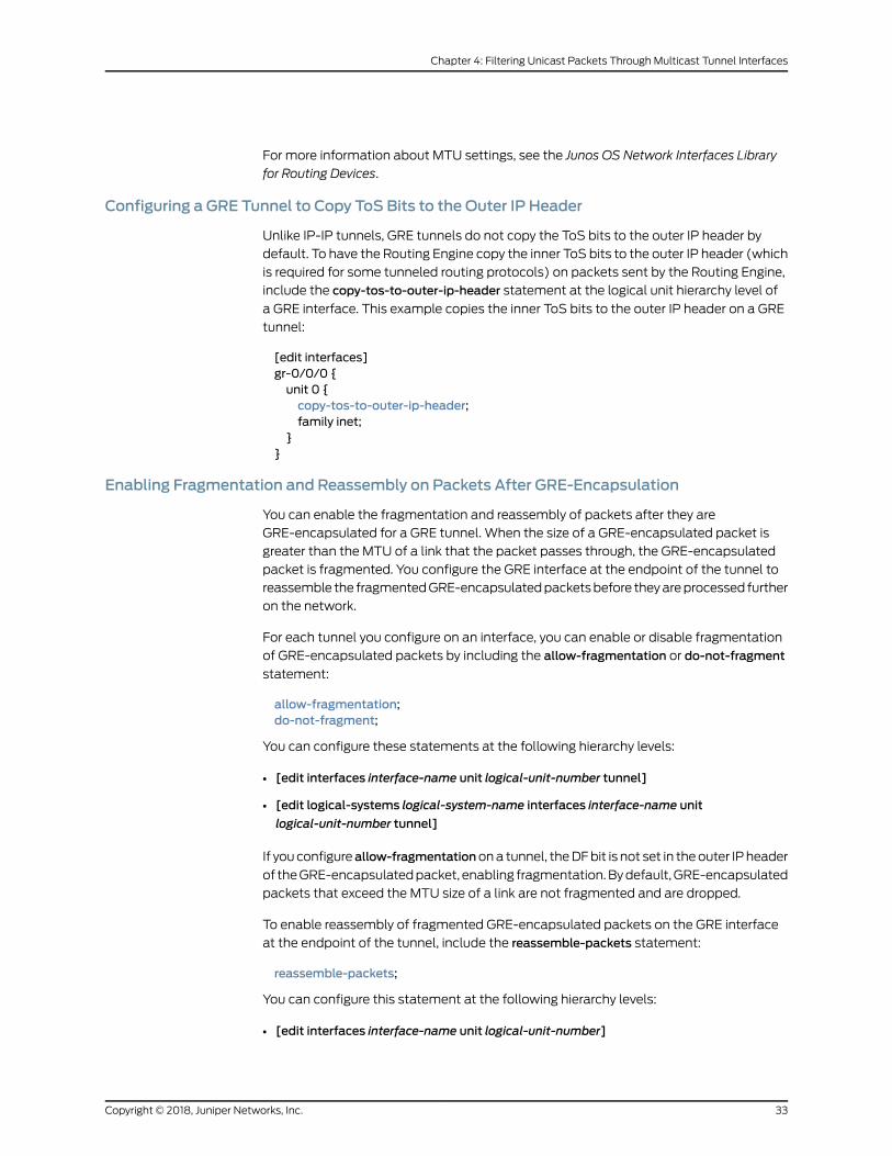
For more information about MTU settings, see the Junos OS Network Interfaces Library
for Routing Devices.
Configuring a GRE Tunnel to Copy ToS Bits to the Outer IP Header
Unlike IP-IP tunnels, GRE tunnels do not copy the ToS bits to the outer IP header by
default. To have the Routing Engine copy the inner ToS bits to the outer IP header (which
is required for some tunneled routing protocols) on packets sent by the Routing Engine,
include the copy-tos-to-outer-ip-header statement at the logical unit hierarchy level of
a GRE interface. This example copies the inner ToS bits to the outer IP header on a GRE
tunnel:
[edit interfaces]gr-0/0/0 {unit 0 {copy-tos-to-outer-ip-header;family inet;
}}
Enabling Fragmentation and Reassembly on Packets After GRE-Encapsulation
You can enable the fragmentation and reassembly of packets after they are
GRE-encapsulated for a GRE tunnel. When the size of a GRE-encapsulated packet is
greater than the MTU of a link that the packet passes through, the GRE-encapsulated
packet is fragmented. You configure the GRE interface at the endpoint of the tunnel to
reassemble the fragmentedGRE-encapsulatedpacketsbefore theyareprocessed further
on the network.
For each tunnel you configure on an interface, you can enable or disable fragmentation
of GRE-encapsulated packets by including the allow-fragmentation or do-not-fragment
statement:
allow-fragmentation;do-not-fragment;
You can configure these statements at the following hierarchy levels:
• [edit interfaces interface-name unit logical-unit-number tunnel]
• [edit logical-systems logical-system-name interfaces interface-name unit
logical-unit-number tunnel]
If youconfigureallow-fragmentationona tunnel, theDFbit is not set in theouter IPheader
of theGRE-encapsulatedpacket, enabling fragmentation.Bydefault,GRE-encapsulated
packets that exceed the MTU size of a link are not fragmented and are dropped.
To enable reassembly of fragmented GRE-encapsulated packets on the GRE interface
at the endpoint of the tunnel, include the reassemble-packets statement:
reassemble-packets;
You can configure this statement at the following hierarchy levels:
• [edit interfaces interface-name unit logical-unit-number]
33Copyright © 2018, Juniper Networks, Inc.
Chapter 4: Filtering Unicast Packets Through Multicast Tunnel Interfaces
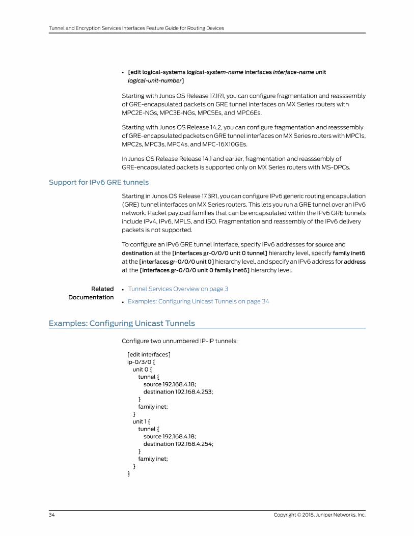
• [edit logical-systems logical-system-name interfaces interface-name unit
logical-unit-number]
Starting with Junos OS Release 17.1R1, you can configure fragmentation and reasssembly
of GRE-encapsulated packets on GRE tunnel interfaces on MX Series routers with
MPC2E-NGs, MPC3E-NGs, MPC5Es, and MPC6Es.
Starting with Junos OS Release 14.2, you can configure fragmentation and reasssembly
ofGRE-encapsulatedpacketsonGRE tunnel interfacesonMXSeries routerswithMPC1s,
MPC2s, MPC3s, MPC4s, and MPC-16X10GEs.
In Junos OS Release Release 14.1 and earlier, fragmentation and reasssembly of
GRE-encapsulated packets is supported only on MX Series routers with MS-DPCs.
Support for IPv6 GRE tunnels
Starting in JunosOSRelease 17.3R1, you can configure IPv6 generic routing encapsulation
(GRE) tunnel interfaces onMXSeries routers. This lets you run aGRE tunnel over an IPv6
network. Packet payload families that can be encapsulated within the IPv6 GRE tunnels
include IPv4, IPv6, MPLS, and ISO. Fragmentation and reassembly of the IPv6 delivery
packets is not supported.
To configure an IPv6 GRE tunnel interface, specify IPv6 addresses for source and
destination at the [interfaces gr-0/0/0 unit 0 tunnel] hierarchy level, specify family inet6
at the [interfacesgr-0/0/0unit0]hierarchy level, and specify an IPv6address foraddress
at the [interfaces gr-0/0/0 unit 0 family inet6] hierarchy level.
RelatedDocumentation
Tunnel Services Overview on page 3•
• Examples: Configuring Unicast Tunnels on page 34
Examples: Configuring Unicast Tunnels
Configure two unnumbered IP-IP tunnels:
[edit interfaces]ip-0/3/0 {unit 0 {tunnel {source 192.168.4.18;destination 192.168.4.253;
}family inet;
}unit 1 {tunnel {source 192.168.4.18;destination 192.168.4.254;
}family inet;
}}
Copyright © 2018, Juniper Networks, Inc.34
Tunnel and Encryption Services Interfaces Feature Guide for Routing Devices
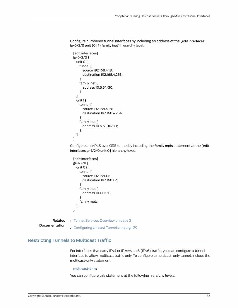
Configure numbered tunnel interfaces by including an address at the [edit interfacesip-0/3/0 unit (0 | 1) family inet] hierarchy level:
[edit interfaces]ip-0/3/0 {unit 0 {tunnel {source 192.168.4.18;destination 192.168.4.253;
}family inet {address 10.5.5.1/30;
}}unit 1 {tunnel {source 192.168.4.18;destination 192.168.4.254;
}family inet {address 10.6.6.100/30;
}}
}
Configure an MPLS over GRE tunnel by including the family mpls statement at the [edit
interfaces gr-1/2/0 unit 0] hierarchy level:
[edit interfaces]gr-1/2/0 {unit 0 {tunnel {source 192.168.1.1;destination 192.168.1.2;
}family inet {address 10.1.1.1/30;
}family mpls;
}}
RelatedDocumentation
Tunnel Services Overview on page 3•
• Configuring Unicast Tunnels on page 29
Restricting Tunnels toMulticast Traffic
For interfaces that carry IPv4 or IP version 6 (IPv6) traffic, you can configure a tunnel
interface to allowmulticast traffic only. To configure amulticast-only tunnel, include the
multicast-only statement:
multicast-only;
You can configure this statement at the following hierarchy levels:
35Copyright © 2018, Juniper Networks, Inc.
Chapter 4: Filtering Unicast Packets Through Multicast Tunnel Interfaces

• [edit interfaces interface-name unit logical-unit-number family family]
• [edit logical-systems logical-system-name interfaces interface-name unit
logical-unit-number family family]
Multicast tunnels filter all unicast packets; if an incoming packet is not destined for a
224/8 or greater prefix, the packet is dropped and a counter is incremented.
You can configure this property on GRE, IP-IP, PIM, andmulticast tunnel (mt) interfaces
only.
NOTE: If your router has a Tunnel Services PIC, the Junos OS automaticallyconfiguresonemulticast tunnel interface(mt) foreachvirtualprivatenetwork
(VPN)youconfigure.Youdonotneedtoconfiguremulticast tunnel interfaces.
RelatedDocumentation
• Tunnel Services Overview on page 3
• Configuring Unicast Tunnels on page 29
Copyright © 2018, Juniper Networks, Inc.36
Tunnel and Encryption Services Interfaces Feature Guide for Routing Devices
CHAPTER 5
Connecting Logical SystemsUsingLogicalTunnel Interfaces
• Configuring Logical Tunnel Interfaces on page 37
• Example: Configuring Logical Tunnels on page 39
• Redundant Logical Tunnels Overview on page 41
• Configuring Redundant Logical Tunnels on page 44
• Example: Configuring Redundant Logical Tunnels on page 45
Configuring Logical Tunnel Interfaces
Logical tunnel (lt-) interfaces provide quite different services depending on the host
router:
• OnM Series, MX Series, and T Series routers, logical tunnel interfaces allow you to
connect logical systems, virtual routers, orVPN instances.MSeriesandTSeries routers
must be equipped with a Tunnel Services PIC or an Adaptive Services Module (only
available on M7i routers). MX Series routers must be equipped with a Trio MPC/MIC
module. For more information about connecting these applications, see the Junos OS
VPNs Library for Routing Devices.
• On SRX Series Services Gateways, the logical tunnel interface is used to interconnect
logical systems. See the Logical Systems Feature Guide for Security Devices for
information about using the logical tunnel interface on the SRX Series.
• On ACX Series routers, logical tunnel interfaces allow you to connect a bridge domain
and a pseudowire. Logical systems are not supported on ACX Series routers.
For M Series, MX Series, and T Series routers, see the following section:
• Connecting Logical Systems on page 37
Connecting Logical Systems
To connect two logical systems, you configure a logical tunnel interface on both logical
systems. Then you configure a peer relationship between the logical tunnel interfaces,
thus creating a point-to-point connection.
37Copyright © 2018, Juniper Networks, Inc.

To configure a point-to-point connection between two logical systems, configure the
logical tunnel interface by including the lt-fpc/pic/port statement:
lt-fpc/pic/port {unit logical-unit-number {encapsulation encapsulation;peer-unit unit-number; # peering logical system unit numberdlci dlci-number;family (inet | inet6 | iso | mpls);
}}
You can include this statement at the following hierarchy levels:
• [edit interfaces]
• [edit logical-systems logical-system-name interfaces]
When configuring logical tunnel interfaces, note the following:
• Youcanconfigure each logical tunnel interfacewithoneof the followingencapsulation
types: Ethernet, Ethernet circuit cross-connect (CCC), Ethernet VPLS, Frame Relay,
Frame Relay CCC, VLAN, VLAN CCC, or VLAN VPLS.
• You can configure the IP, IPv6, International Organization for Standardization (ISO),
or MPLS protocol family.
• Do not reconfigure a logical tunnel interface that is an anchor point with pseudowire
devices stacked above it unless you first deactivate all broadband subscribers that are
using the pseudowire subscriber interface.
• The peering logical interfacesmust belong to the same logical tunnel interface derived
from the Tunnel Services PIC or Adaptive Services Module.
• You can configure only one peer unit for each logical interface. For example, unit 0
cannot peer with both unit 1 and unit 2.
• Toenable the logical tunnel interface, youmust configureat least onephysical interface
statement.
• Logical tunnels arenot supportedwithAdaptiveServices,Multiservices, or LinkServices
PICs (but they are supported on theAdaptive ServicesModule onM7i routers, as noted
above).
• OnM Series routers other than the M40e router, logical tunnel interfaces require an
Enhanced Flexible PIC Concentrator (FPC).
• OnMX Series routers, logical tunnel interfaces require Trio MPC/MICmodules. They
do not require a Tunnel Services PIC in the same system.
For more information about configuring logical systems, see the Junos OS Routing
Protocols Library.
RelatedDocumentation
Tunnel Services Overview on page 3•
• Example: Configuring Logical Tunnels on page 39
Copyright © 2018, Juniper Networks, Inc.38
Tunnel and Encryption Services Interfaces Feature Guide for Routing Devices
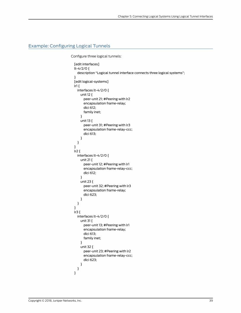
Example: Configuring Logical Tunnels
Configure three logical tunnels:
[edit interfaces]lt-4/2/0 {description “Logical tunnel interface connects three logical systems”;
}[edit logical-systems]lr1 {interfaces lt-4/2/0 {unit 12 {peer-unit 21; #Peering with lr2encapsulation frame-relay;dlci 612;family inet;
}unit 13 {peer-unit 31; #Peering with lr3encapsulation frame-relay-ccc;dlci 613;
}}
}lr2 {interfaces lt-4/2/0 {unit 21 {peer-unit 12; #Peering with lr1encapsulation frame-relay-ccc;dlci 612;
}unit 23 {peer-unit 32; #Peering with lr3encapsulation frame-relay;dlci 623;
}}
}lr3 {interfaces lt-4/2/0 {unit 31 {peer-unit 13; #Peering with lr1encapsulation frame-relay;dlci 613;family inet;
}unit 32 {peer-unit 23; #Peering with lr2encapsulation frame-relay-ccc;dlci 623;
}}
}
39Copyright © 2018, Juniper Networks, Inc.
Chapter 5: Connecting Logical Systems Using Logical Tunnel Interfaces

RelatedDocumentation
Tunnel Services Overview on page 3•
• Configuring Logical Tunnel Interfaces on page 37
Copyright © 2018, Juniper Networks, Inc.40
Tunnel and Encryption Services Interfaces Feature Guide for Routing Devices

Redundant Logical Tunnels Overview
41Copyright © 2018, Juniper Networks, Inc.
Chapter 5: Connecting Logical Systems Using Logical Tunnel Interfaces

You can connect two devices, such as an access-facing device and a core-facing device,
through logical tunnels. To provide redundancy for the tunnels, you can create and
configure multiple physical logical tunnels and add them to a virtual redundant logical
tunnel.
NOTE: Redundant logical tunnels are supported only on MX Series routerswith MPCs. MX Series Virtual Chassis does not support redundant logicaltunnels.
NOTE: Redundant logical tunnels are not supported currently in MX SeriesVirtual Chassis.
Forexample, inanMPLSaccessnetwork, youcanconfiguremultiplepseudowiresbetween
an access node and anMXSeries router withMPCs and add them to a redundant logical
tunnel. You can then addmultiple logical tunnels to the redundant logical tunnel.
Figure 2 on page 42 shows a redundant logical tunnel between the access node and the
MX Series router.
Figure 2: Redundant Logical Tunnels
The redundant logical tunnel has peer logical interfaces at each end, rlt0.0 and rlt0.1.
You can configure router features on these interfaces for the redundant logical tunnel
and its members.
Eachmember logical tunnel haspeer logical interfaces. In Figure2onpage42, lt-0/0/10.0
and lt-0/0/10.1 are peers.
TheMXSeries router performs IP lookup in the Layer 3VPN routing and forwarding (VRF)
table on the router where the pseudowires that are grouped in logical tunnels terminate.
Redundant Logical Tunnel Configuration
Copyright © 2018, Juniper Networks, Inc.42
Tunnel and Encryption Services Interfaces Feature Guide for Routing Devices
In JunosOSReleases 14.1R1 and earlier, you can create up to 16 redundant logical tunnels,
depending on the number of Packet Forwarding Engines and the number of loopback
interfacesoneachPacketForwardingEngineonyourdevice.Starting in JunosOSRelease
14.2 and for 13.3R3 and 14.1R2, the valid range for device-count is from 1 to 255.
You can add up to 32 logical tunnels as members of a redundant logical tunnel.
When youaddmore than twomembers to the redundant logical tunnel, they are in active
mode. The traffic is load-balanced over all the tunnel members.
When you add only twomembers to the redundant logical tunnel, you can configure the
members in one of these ways:
• Bothmembers in active mode
• Onemember in active mode and the other in backupmode
Redundant Logical Tunnel Failure Detection and Failover
A logical tunnel fails and is removed from the redundant logical tunnel group, and the
backup logical tunnel becomes active due to one of these events:
• A hardware failure on the MPCmodule occurs.
• AnMPC failure occurs due to amicrokernel crash.
• The MPCmodule is administratively shut down and removed from the redundant
logical tunnel.
• A power failure on the MPCmodule occurs.
NOTE: You can decrease the time it takes for failure detection and failoverto occur. Configure the enhanced-ip statement at the [edit chassis
network-services]hierarchy level toenablePacketForwardingEngine liveliness
detection.
Release History Table DescriptionRelease
Starting in JunosOSRelease 14.2 and for 13.3R3and 14.1R2, the valid rangefor device-count is from 1 to 255.
14.2
RelatedDocumentation
Example: Configuring Redundant Logical Tunnels on page 45•
• Pseudowire Subscriber Logical Interfaces Overview
• Configuring Logical Tunnel Interfaces on page 37
• Configuring Redundant Logical Tunnels on page 44
• Configuring a Pseudowire Subscriber Logical Interface Device
43Copyright © 2018, Juniper Networks, Inc.
Chapter 5: Connecting Logical Systems Using Logical Tunnel Interfaces
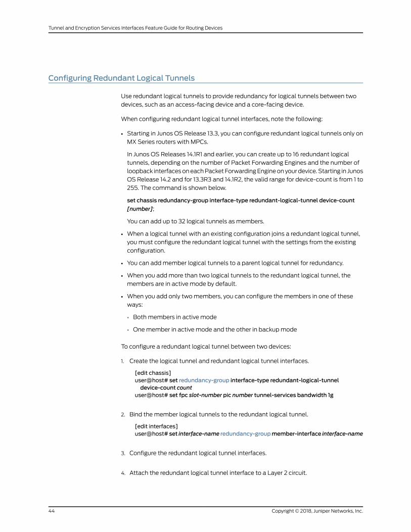
Configuring Redundant Logical Tunnels
Use redundant logical tunnels to provide redundancy for logical tunnels between two
devices, such as an access-facing device and a core-facing device.
When configuring redundant logical tunnel interfaces, note the following:
• Starting in Junos OS Release 13.3, you can configure redundant logical tunnels only on
MX Series routers with MPCs.
In Junos OS Releases 14.1R1 and earlier, you can create up to 16 redundant logical
tunnels, depending on the number of Packet Forwarding Engines and the number of
loopback interfacesoneachPacket ForwardingEngineonyourdevice. Starting in Junos
OS Release 14.2 and for 13.3R3 and 14.1R2, the valid range for device-count is from 1 to
255. The command is shown below.
set chassis redundancy-group interface-type redundant-logical-tunnel device-count
[number];
You can add up to 32 logical tunnels as members.
• When a logical tunnel with an existing configuration joins a redundant logical tunnel,
you must configure the redundant logical tunnel with the settings from the existing
configuration.
• You can addmember logical tunnels to a parent logical tunnel for redundancy.
• When you addmore than two logical tunnels to the redundant logical tunnel, the
members are in active mode by default.
• When you add only twomembers, you can configure the members in one of these
ways:
• Bothmembers in active mode
• Onemember in active mode and the other in backupmode
To configure a redundant logical tunnel between two devices:
1. Create the logical tunnel and redundant logical tunnel interfaces.
[edit chassis]user@host# set redundancy-group interface-type redundant-logical-tunneldevice-count count
user@host# set fpc slot-number pic number tunnel-services bandwidth 1g
2. Bind themember logical tunnels to the redundant logical tunnel.
[edit interfaces]user@host# set interface-name redundancy-groupmember-interface interface-name
3. Configure the redundant logical tunnel interfaces.
4. Attach the redundant logical tunnel interface to a Layer 2 circuit.
Copyright © 2018, Juniper Networks, Inc.44
Tunnel and Encryption Services Interfaces Feature Guide for Routing Devices

5. Add the peer redundant logical tunnel interface to a Layer 3 VRF instance.
6. Configure MPLS and LDP in the pseudowires and the Layer 3 VPN.
[edit protocols]user@host# setmpls no-cspfuser@host# setmpls interface alluser@host# set ldp interface all
7. Configure BGP in the Layer 3 VPN.
8. Configure OSPF on the core-facing interfaces and the router local loopback interface.
9. Set the policy options for BGP.
10. Set the router ID and the autonomous system (AS) number.
Release History Table DescriptionRelease
Starting in Junos OS Release 14.2 and for 13.3R3 and 14.1R2, the valid rangefor device-count is from 1 to 255.
14.2
Starting in JunosOSRelease 13.3, youcanconfigure redundant logical tunnelsonly on MX Series routers with MPCs.
13.3
RelatedDocumentation
Example: Configuring Redundant Logical Tunnels on page 45•
• Redundant Logical Tunnels Overview on page 41
Example: Configuring Redundant Logical Tunnels
This example shows how to configure redundant logical tunnels in an MPLS access
network.
• Requirements on page 45
• Overview on page 46
• Configuration on page 47
• Verification on page 53
Requirements
In Junos OSRelease 13.3 or later, you can configure redundant logical tunnels only onMX
Series routers with MPCs.
45Copyright © 2018, Juniper Networks, Inc.
Chapter 5: Connecting Logical Systems Using Logical Tunnel Interfaces
Overview
When a logical tunnel with an existing configuration joins a redundant logical tunnel, you
must configure the redundant logical tunnel with the settings from the existing
configuration.
You can addmember logical tunnels to a parent logical tunnel for redundancy.
OnMXSeries routers withMPCs, you can configure redundant logical tunnels as follows:
• In Junos OS Releases 14.1R1 and earlier, you can create up to 16 redundant logical
tunnels, depending on the number of Packet Forwarding Engines and the number of
loopback interfacesoneachPacket ForwardingEngineonyourdevice. Starting in Junos
OS Release 14.2 and for 13.3R3 and 14.1R2, the valid range for device-count is from 1 to
255. The command is shown below.
set chassis redundancy-group interface-type redundant-logical-tunnel device-count
[number];
• You can add up to 32 logical tunnels as members.
• Whenyouaddmore than two logical tunnels toa redundant logical tunnel, themembers
are in active mode by default.
• When you add only twomembers, you can configure the members in one of these
ways:
• Bothmembers in active mode
• Onemember in active mode and the other in backupmode
Topology
Figure 2 on page 42 shows a redundant logical tunnel between the access node and the
MX Series router in an MPLS access network.
Copyright © 2018, Juniper Networks, Inc.46
Tunnel and Encryption Services Interfaces Feature Guide for Routing Devices
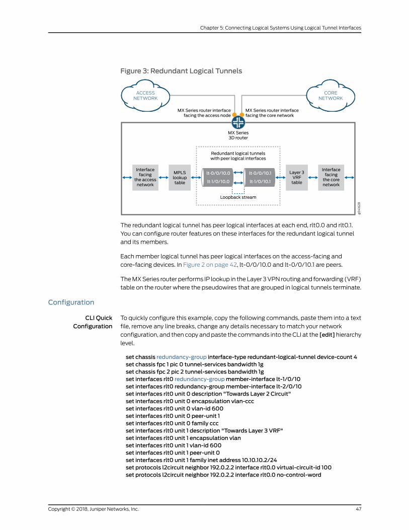
Figure 3: Redundant Logical Tunnels
The redundant logical tunnel has peer logical interfaces at each end, rlt0.0 and rlt0.1.
You can configure router features on these interfaces for the redundant logical tunnel
and its members.
Eachmember logical tunnel has peer logical interfaces on the access-facing and
core-facing devices. In Figure 2 on page 42, lt-0/0/10.0 and lt-0/0/10.1 are peers.
TheMXSeries router performs IP lookup in the Layer 3VPN routing and forwarding (VRF)
table on the router where the pseudowires that are grouped in logical tunnels terminate.
Configuration
CLI QuickConfiguration
To quickly configure this example, copy the following commands, paste them into a text
file, remove any line breaks, change any details necessary to match your network
configuration, and then copy andpaste the commands into theCLI at the [edit]hierarchy
level.
set chassis redundancy-group interface-type redundant-logical-tunnel device-count 4set chassis fpc 1 pic 0 tunnel-services bandwidth 1gset chassis fpc 2 pic 2 tunnel-services bandwidth 1gset interfaces rlt0 redundancy-groupmember-interface lt-1/0/10set interfaces rlt0 redundancy-groupmember-interface lt-2/0/10set interfaces rlt0 unit 0 description "Towards Layer 2 Circuit"set interfaces rlt0 unit 0 encapsulation vlan-cccset interfaces rlt0 unit 0 vlan-id 600set interfaces rlt0 unit 0 peer-unit 1set interfaces rlt0 unit 0 family cccset interfaces rlt0 unit 1 description "Towards Layer 3 VRF"set interfaces rlt0 unit 1 encapsulation vlanset interfaces rlt0 unit 1 vlan-id 600set interfaces rlt0 unit 1 peer-unit 0set interfaces rlt0 unit 1 family inet address 10.10.10.2/24set protocols l2circuit neighbor 192.0.2.2 interface rlt0.0 virtual-circuit-id 100set protocols l2circuit neighbor 192.0.2.2 interface rlt0.0 no-control-word
47Copyright © 2018, Juniper Networks, Inc.
Chapter 5: Connecting Logical Systems Using Logical Tunnel Interfaces
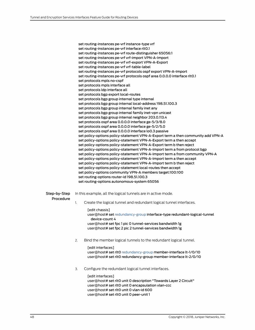
set routing-instances pe-vrf instance-type vrfset routing-instances pe-vrf interface rlt0.1set routing-instances pe-vrf route-distinguisher 65056:1set routing-instances pe-vrf vrf-import VPN-A-Importset routing-instances pe-vrf vrf-export VPN-A-Exportset routing-instances pe-vrf vrf-table-labelset routing-instances pe-vrf protocols ospf export VPN-A-Importset routing-instances pe-vrf protocols ospf area 0.0.0.0 interface rlt0.1set protocolsmpls no-cspfset protocolsmpls interface allset protocols ldp interface allset protocols bgp export local-routesset protocols bgp group internal type internalset protocols bgp group internal local-address 198.51.100.3set protocols bgp group internal family inet anyset protocols bgp group internal family inet-vpn unicastset protocols bgp group internal neighbor 203.0.113.4set protocols ospf area 0.0.0.0 interface ge-5/3/8.0set protocols ospf area 0.0.0.0 interface ge-5/2/5.0set protocols ospf area 0.0.0.0 interface lo0.3 passiveset policy-options policy-statement VPN-A-Export term a then community add VPN-Aset policy-options policy-statement VPN-A-Export term a then acceptset policy-options policy-statement VPN-A-Export term b then rejectset policy-options policy-statement VPN-A-Import term a from protocol bgpset policy-options policy-statement VPN-A-Import term a from community VPN-Aset policy-options policy-statement VPN-A-Import term a then acceptset policy-options policy-statement VPN-A-Import term b then rejectset policy-options policy-statement local-routes then acceptset policy-options community VPN-Amembers target:100:100set routing-options router-id 198.51.100.3set routing-options autonomous-system 65056
Step-by-StepProcedure
In this example, all the logical tunnels are in active mode.
Create the logical tunnel and redundant logical tunnel interfaces.1.
[edit chassis]user@host# set redundancy-group interface-type redundant-logical-tunneldevice-count 4
user@host# set fpc 1 pic 0 tunnel-services bandwidth 1guser@host# set fpc 2 pic 2 tunnel-services bandwidth 1g
2. Bind themember logical tunnels to the redundant logical tunnel.
[edit interfaces]user@host# set rlt0 redundancy-groupmember-interface lt-1/0/10user@host# set rlt0 redundancy-groupmember-interface lt-2/0/10
3. Configure the redundant logical tunnel interfaces.
[edit interfaces]user@host# set rlt0 unit 0 description "Towards Layer 2 Circuit"user@host# set rlt0 unit 0 encapsulation vlan-cccuser@host# set rlt0 unit 0 vlan-id 600user@host# set rlt0 unit 0 peer-unit 1
Copyright © 2018, Juniper Networks, Inc.48
Tunnel and Encryption Services Interfaces Feature Guide for Routing Devices

user@host# set rlt0 unit 0 family ccc
user@host# set rlt0 unit 1 description "Towards Layer 3 VRF"user@host# set rlt0 unit 1 encapsulation vlanuser@host# set rlt0 unit 1 vlan-id 600user@host# set rlt0 unit 1 peer-unit 0user@host# set rlt0 unit 1 family inet address 10.10.10.2/24
4. Attach rlt0.0 to a Layer 2 circuit.
[edit protocols]user@host# set l2circuit neighbor 192.0.2.2 interface rlt0.0 virtual-circuit-id 100user@host# set l2circuit neighbor 192.0.2.2 interface rlt0.0 no-control-word
5. Add rlt0.1 to a Layer 3 VRF instance.
[edit routing-instances]user@host# set pe-vrf instance-type vrfuser@host# set pe-vrf interface rlt0.1user@host# set pe-vrf route-distinguisher 65056:1user@host# set pe-vrf vrf-import VPN-A-Importuser@host# set pe-vrf vrf-export VPN-A-Exportuser@host# set pe-vrf vrf-table-labeluser@host# set pe-vrf protocols ospf export VPN-A-Importuser@host# set pe-vrf protocols ospf area 0.0.0.0 interface rlt0.1
6. Configure MPLS and LDP in the pseudowires and the Layer 3 VPN.
[edit protocols]user@host# setmpls no-cspfuser@host# setmpls interface alluser@host# set ldp interface all
7. Configure BGP in the Layer 3 VPN.
[edit protocols]user@host# set bgp export local-routesuser@host# set bgp group internal type internaluser@host# set bgp group internal local-address 198.51.100.3user@host# set bgp group internal family inet anyuser@host# set bgp group internal family inet-vpn unicastuser@host# set bgp group internal neighbor 203.0.113.4
8. ConfigureOSPFon thecore-facing interfacesand the router local loopback interface.
[edit protocols]user@host# set ospf area 0.0.0.0 interface ge-5/3/8.0user@host# set ospf area 0.0.0.0 interface ge-5/2/5.0user@host# set ospf area 0.0.0.0 interface lo0.3 passive
9. Set the policy options for BGP.
[edit policy-options]user@host#setpolicy-statementVPN-A-Export termathencommunityaddVPN-A
49Copyright © 2018, Juniper Networks, Inc.
Chapter 5: Connecting Logical Systems Using Logical Tunnel Interfaces
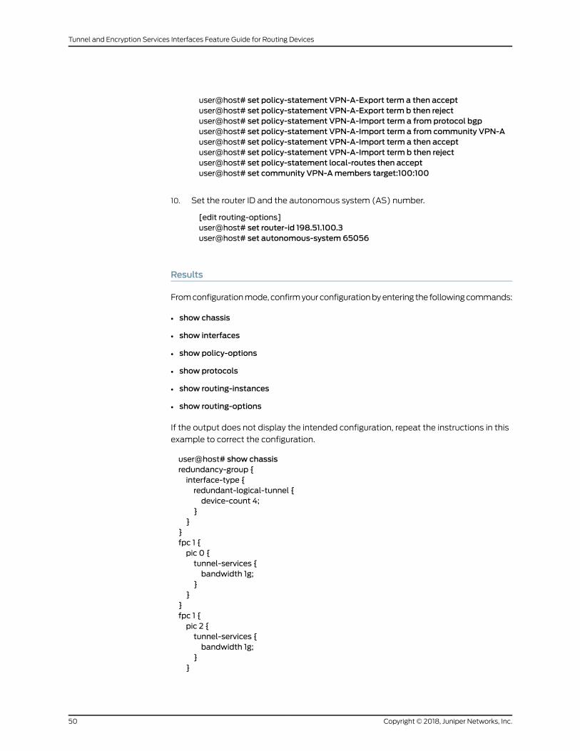
user@host# set policy-statement VPN-A-Export term a then acceptuser@host# set policy-statement VPN-A-Export term b then rejectuser@host# set policy-statement VPN-A-Import term a from protocol bgpuser@host# set policy-statement VPN-A-Import term a from community VPN-Auser@host# set policy-statement VPN-A-Import term a then acceptuser@host# set policy-statement VPN-A-Import term b then rejectuser@host# set policy-statement local-routes then acceptuser@host# set community VPN-Amembers target:100:100
10. Set the router ID and the autonomous system (AS) number.
[edit routing-options]user@host# set router-id 198.51.100.3user@host# set autonomous-system 65056
Results
Fromconfigurationmode, confirmyourconfigurationbyentering the followingcommands:
• show chassis
• show interfaces
• show policy-options
• show protocols
• show routing-instances
• show routing-options
If the output does not display the intended configuration, repeat the instructions in this
example to correct the configuration.
user@host# show chassisredundancy-group {interface-type {redundant-logical-tunnel {device-count 4;
}}
}fpc 1 {pic 0 {tunnel-services {bandwidth 1g;
}}
}fpc 1 {pic 2 {tunnel-services {bandwidth 1g;
}}
Copyright © 2018, Juniper Networks, Inc.50
Tunnel and Encryption Services Interfaces Feature Guide for Routing Devices
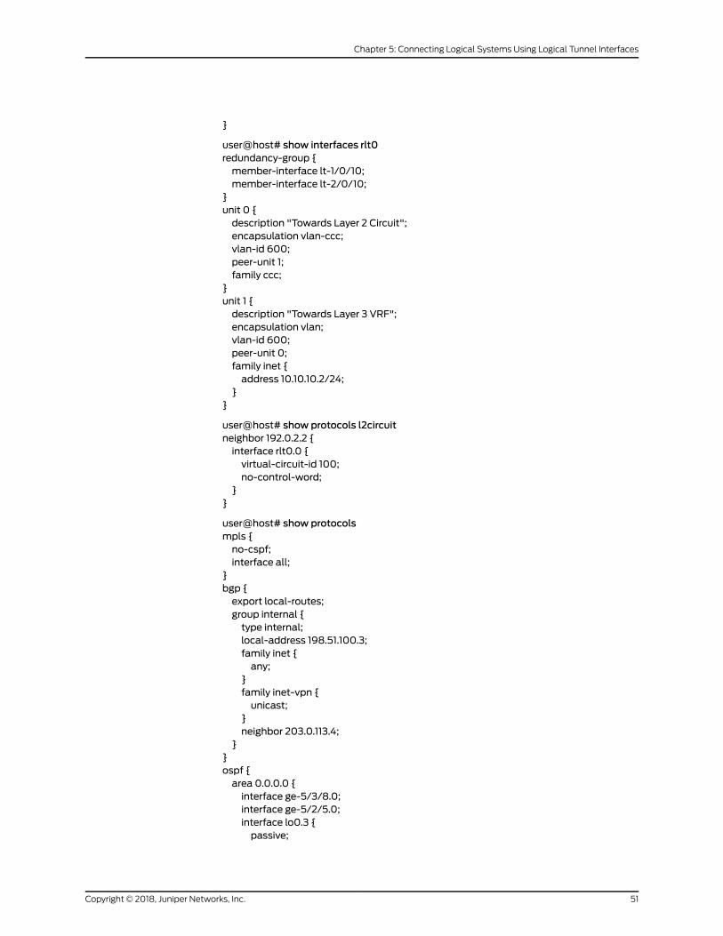
}
user@host# show interfaces rlt0redundancy-group {member-interface lt-1/0/10;member-interface lt-2/0/10;
}unit 0 {description "Towards Layer 2 Circuit";encapsulation vlan-ccc;vlan-id 600;peer-unit 1;family ccc;
}unit 1 {description "Towards Layer 3 VRF";encapsulation vlan;vlan-id 600;peer-unit 0;family inet {address 10.10.10.2/24;
}}
user@host# show protocols l2circuitneighbor 192.0.2.2 {interface rlt0.0 {virtual-circuit-id 100;no-control-word;
}}
user@host# show protocolsmpls {no-cspf;interface all;
}bgp {export local-routes;group internal {type internal;local-address 198.51.100.3;family inet {any;
}family inet-vpn {unicast;
}neighbor 203.0.113.4;
}}ospf {area 0.0.0.0 {interface ge-5/3/8.0;interface ge-5/2/5.0;interface lo0.3 {passive;
51Copyright © 2018, Juniper Networks, Inc.
Chapter 5: Connecting Logical Systems Using Logical Tunnel Interfaces
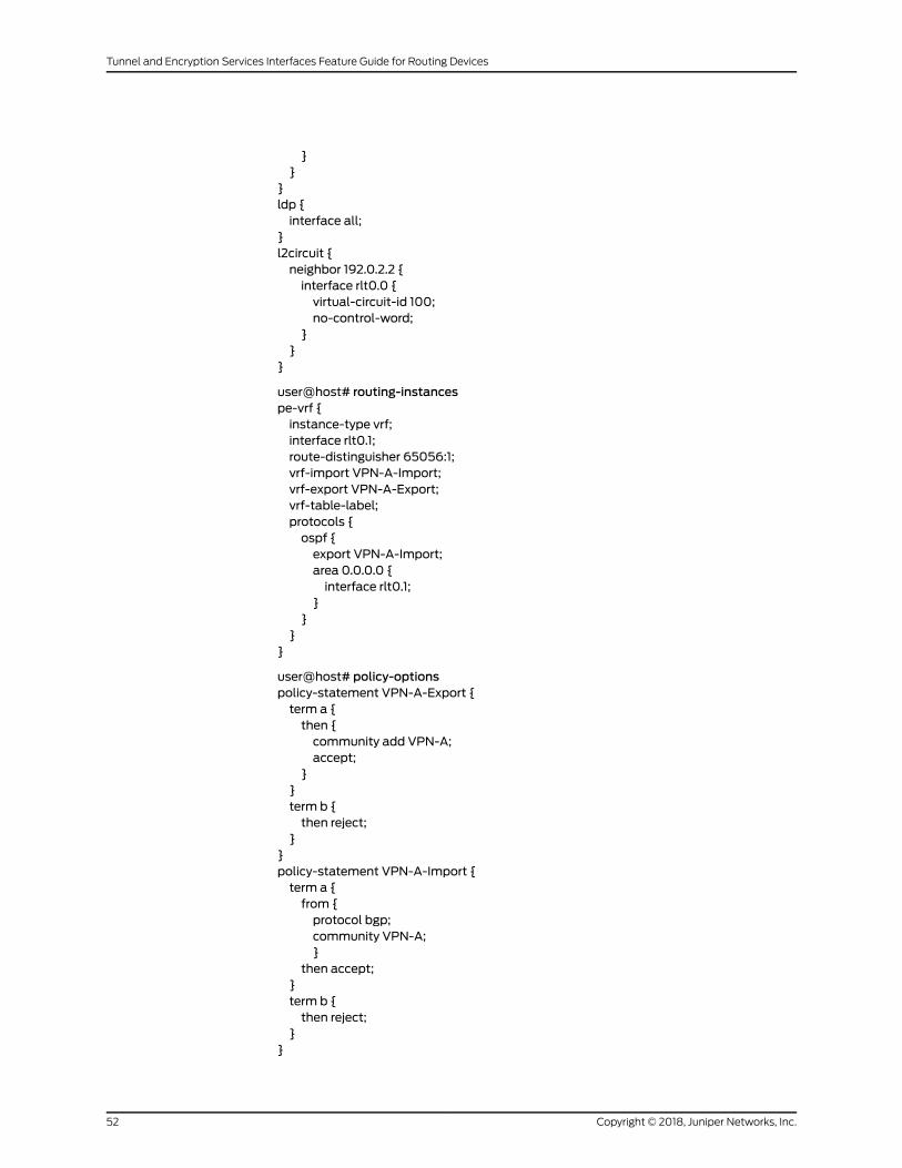
}}
}ldp {interface all;
}l2circuit {neighbor 192.0.2.2 {interface rlt0.0 {virtual-circuit-id 100;no-control-word;
}}
}
user@host# routing-instancespe-vrf {instance-type vrf;interface rlt0.1;route-distinguisher 65056:1;vrf-import VPN-A-Import;vrf-export VPN-A-Export;vrf-table-label;protocols {ospf {export VPN-A-Import;area 0.0.0.0 {interface rlt0.1;
}}
}}
user@host# policy-optionspolicy-statement VPN-A-Export {term a {then {community add VPN-A;accept;
}}term b {then reject;
}}policy-statement VPN-A-Import {term a {from {protocol bgp;community VPN-A;}
then accept;}term b {then reject;
}}
Copyright © 2018, Juniper Networks, Inc.52
Tunnel and Encryption Services Interfaces Feature Guide for Routing Devices
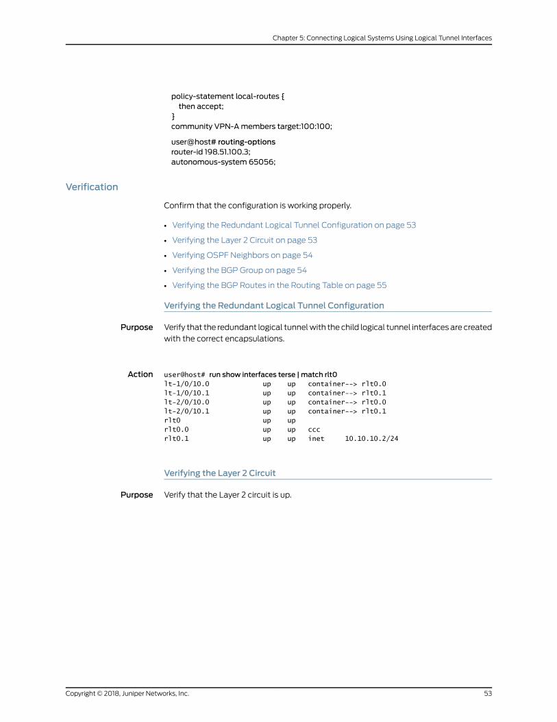
policy-statement local-routes {then accept;
}community VPN-Amembers target:100:100;
user@host# routing-optionsrouter-id 198.51.100.3;autonomous-system 65056;
Verification
Confirm that the configuration is working properly.
• Verifying the Redundant Logical Tunnel Configuration on page 53
• Verifying the Layer 2 Circuit on page 53
• Verifying OSPF Neighbors on page 54
• Verifying the BGP Group on page 54
• Verifying the BGP Routes in the Routing Table on page 55
Verifying the Redundant Logical Tunnel Configuration
Purpose Verify that the redundant logical tunnelwith the child logical tunnel interfacesare created
with the correct encapsulations.
Action user@host# run show interfaces terse | match rlt0lt-1/0/10.0 up up container--> rlt0.0lt-1/0/10.1 up up container--> rlt0.1lt-2/0/10.0 up up container--> rlt0.0lt-2/0/10.1 up up container--> rlt0.1rlt0 up uprlt0.0 up up cccrlt0.1 up up inet 10.10.10.2/24
Verifying the Layer 2 Circuit
Purpose Verify that the Layer 2 circuit is up.
53Copyright © 2018, Juniper Networks, Inc.
Chapter 5: Connecting Logical Systems Using Logical Tunnel Interfaces
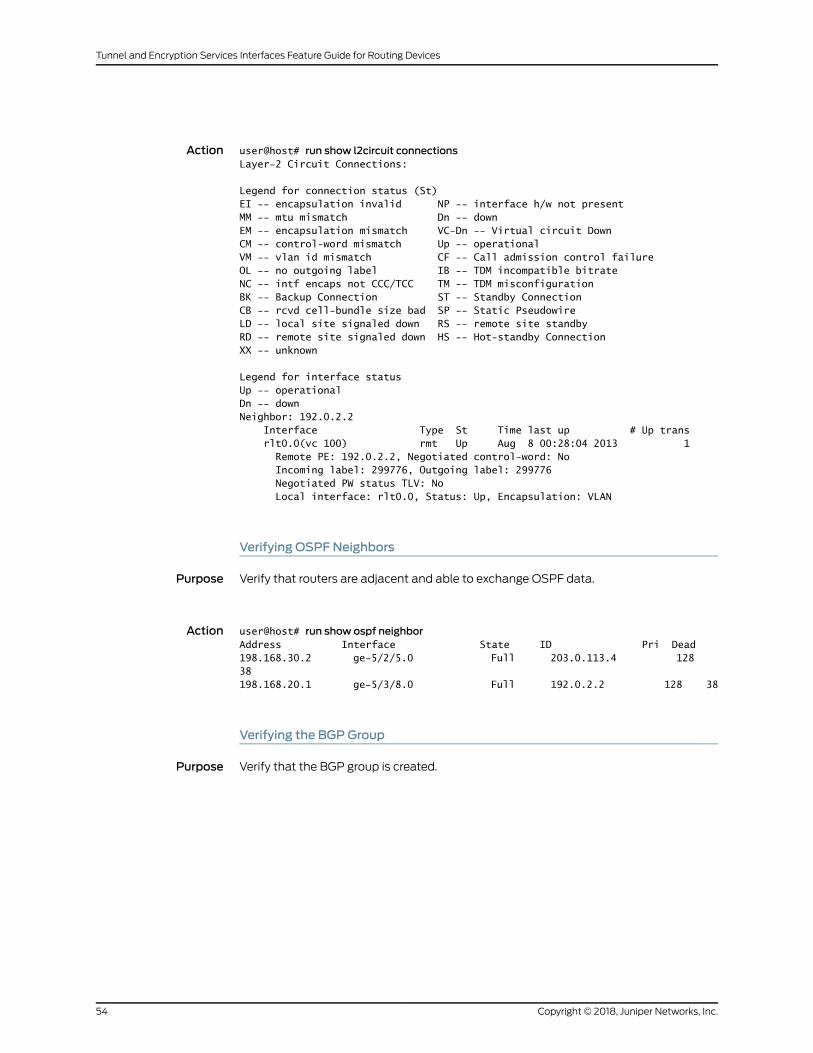
Action user@host# run show l2circuit connectionsLayer-2 Circuit Connections:
Legend for connection status (St) EI -- encapsulation invalid NP -- interface h/w not present MM -- mtu mismatch Dn -- down EM -- encapsulation mismatch VC-Dn -- Virtual circuit Down CM -- control-word mismatch Up -- operational VM -- vlan id mismatch CF -- Call admission control failureOL -- no outgoing label IB -- TDM incompatible bitrate NC -- intf encaps not CCC/TCC TM -- TDM misconfiguration BK -- Backup Connection ST -- Standby ConnectionCB -- rcvd cell-bundle size bad SP -- Static PseudowireLD -- local site signaled down RS -- remote site standbyRD -- remote site signaled down HS -- Hot-standby ConnectionXX -- unknown
Legend for interface status Up -- operational Dn -- down Neighbor: 192.0.2.2 Interface Type St Time last up # Up trans rlt0.0(vc 100) rmt Up Aug 8 00:28:04 2013 1 Remote PE: 192.0.2.2, Negotiated control-word: No Incoming label: 299776, Outgoing label: 299776 Negotiated PW status TLV: No Local interface: rlt0.0, Status: Up, Encapsulation: VLAN
Verifying OSPF Neighbors
Purpose Verify that routers are adjacent and able to exchange OSPF data.
Action user@host# run show ospf neighborAddress Interface State ID Pri Dead198.168.30.2 ge-5/2/5.0 Full 203.0.113.4 128 38198.168.20.1 ge-5/3/8.0 Full 192.0.2.2 128 38
Verifying the BGPGroup
Purpose Verify that the BGP group is created.
Copyright © 2018, Juniper Networks, Inc.54
Tunnel and Encryption Services Interfaces Feature Guide for Routing Devices
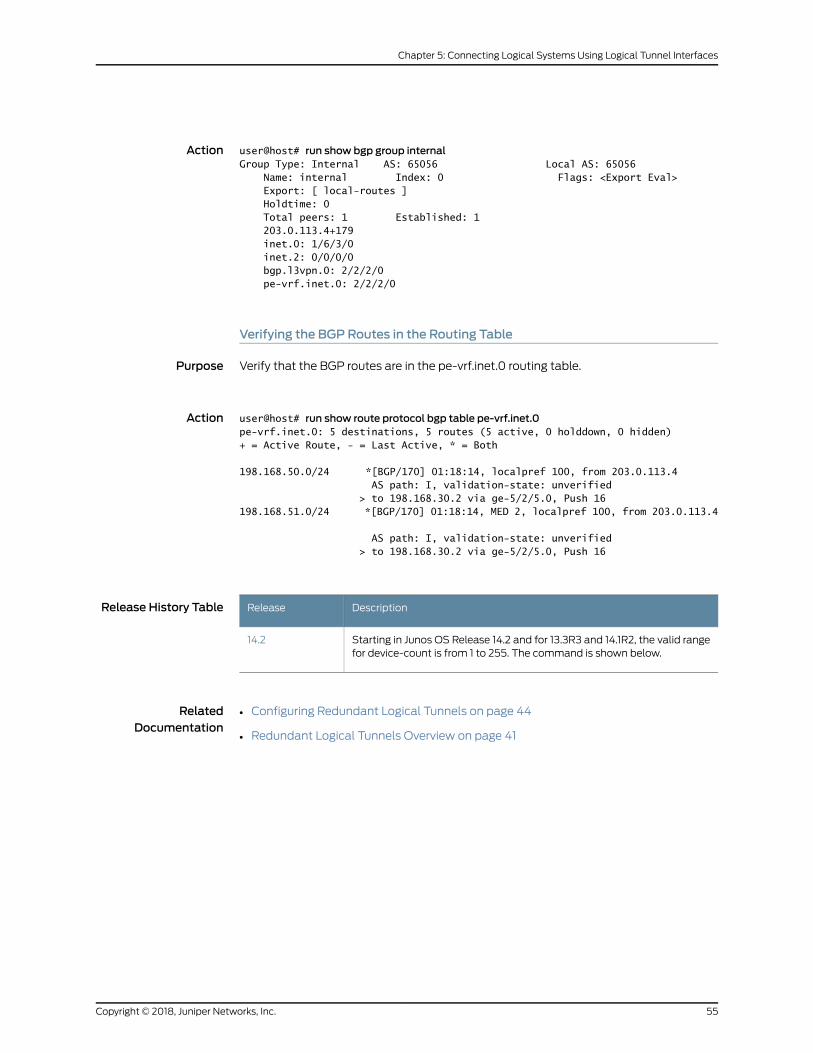
Action user@host# run show bgp group internalGroup Type: Internal AS: 65056 Local AS: 65056 Name: internal Index: 0 Flags: <Export Eval> Export: [ local-routes ] Holdtime: 0 Total peers: 1 Established: 1 203.0.113.4+179 inet.0: 1/6/3/0 inet.2: 0/0/0/0 bgp.l3vpn.0: 2/2/2/0 pe-vrf.inet.0: 2/2/2/0
Verifying the BGP Routes in the Routing Table
Purpose Verify that the BGP routes are in the pe-vrf.inet.0 routing table.
Action user@host# run show route protocol bgp table pe-vrf.inet.0pe-vrf.inet.0: 5 destinations, 5 routes (5 active, 0 holddown, 0 hidden)+ = Active Route, - = Last Active, * = Both
198.168.50.0/24 *[BGP/170] 01:18:14, localpref 100, from 203.0.113.4 AS path: I, validation-state: unverified > to 198.168.30.2 via ge-5/2/5.0, Push 16198.168.51.0/24 *[BGP/170] 01:18:14, MED 2, localpref 100, from 203.0.113.4
AS path: I, validation-state: unverified > to 198.168.30.2 via ge-5/2/5.0, Push 16
Release History Table DescriptionRelease
Starting in Junos OS Release 14.2 and for 13.3R3 and 14.1R2, the valid rangefor device-count is from 1 to 255. The command is shown below.
14.2
RelatedDocumentation
• Configuring Redundant Logical Tunnels on page 44
• Redundant Logical Tunnels Overview on page 41
55Copyright © 2018, Juniper Networks, Inc.
Chapter 5: Connecting Logical Systems Using Logical Tunnel Interfaces

Copyright © 2018, Juniper Networks, Inc.56
Tunnel and Encryption Services Interfaces Feature Guide for Routing Devices
CHAPTER 6
Configuring Layer 2 Ethernet Services overGRE Tunnel Interfaces
• Layer 2 Services over GRE Tunnel Interfaces on MX Series with MPCs on page 57
• Format of GRE Frames and Processing of GRE Interfaces for Layer 2 Ethernet
Packets on page 58
• Guidelines for Configuring Layer 2 Ethernet Traffic Over GRE Tunnels on page 59
• SampleScenariosofConfiguringLayer 2EthernetTrafficOverGRETunnelsonpage60
• Configuring Layer 2 Services over GRE Logical Interfaces in Bridge Domains on page 61
• Example: Configuring Layer 2 Services Over GRE Logical Interfaces in Bridge
Domains on page 62
Layer 2 Services over GRE Tunnel Interfaces onMX Series with MPCs
Starting in Junos OS Release 15.1, you can configure Layer 2 Ethernet services over GRE
interfaces (gr-fpc/pic/port to use GRE encapsulation).
The outputs of the show bridgemac-table and show vplsmac-table commands have
been enhanced to display theMAC addresses learned on a GRE logical interface and the
status ofMACaddress learning properties in theMACaddress andMAC flags fields. Also,
the L2 Routing Instance and L3 Routing Instance fields are added to the output of the
show interfaces gr command to display the names of the routing instances associated
with the GRE interfaces are displayed.
To enable Layer 2 Ethernet packets to be terminated onGRE tunnels, youmust configure
the bridge domain protocol family on the gr- interfaces and associate the gr- interfaces
with the bridge domain. Youmust configure theGRE interfaces as core-facing interfaces,
and they must be access or trunk interfaces. To configure the bridge domain family on
gr- interfaces, include the family bridge statement at the [edit interfaces gr-fpc/pic/port
unit logical-unit-number] hierarchy level. To associate the gr- interface with a bridge
domain, include the interface gr-fpc/pic/port statement at the [edit routing-instances
routing-instance-name bridge-domains bridge-domain-name] hierarchy level.
You can associate GRE interfaces in a bridge domain with the corresponding VLAN ID or
list ofVLAN IDs inabridgedomainby including the vlan-id (all | none |number) statement
or the vlan-id-list [ vlan-id-numbers ] statement at the [edit bridge-domains
bridge-domain-name] hierarchy level. The VLAN IDs configured for the bridge domain
57Copyright © 2018, Juniper Networks, Inc.
mustmatchwith the VLAN IDs that you configure for GRE interfaces by using the vlan-id
(all | none | number) statement or the vlan-id-list [ vlan-id-numbers ] statement at the
[edit interfaces gr-fpc/pic/port unit logical-unit-number] hierarchy level. You can also
configureGRE interfaceswithinabridgedomainassociatedwithavirtual switch instance.
Layer 2 Ethernet packets over GRE tunnels are also supported with the GRE key option.
The gre-key match condition allows a user to match against the GRE key field, which is
an optional field in GRE encapsulated packets. The key can bematched as a single key
value, a range of key values, or both.
RelatedDocumentation
Guidelines for Configuring Layer 2 Ethernet Traffic Over GRE Tunnels on page 59•
• Configuring Layer 2 Services over GRE Logical Interfaces in Bridge Domains on page 61
Format of GRE Frames and Processing of GRE Interfaces for Layer 2 Ethernet Packets
The GRE frame contains the outer MAC header, outer IP header, GRE header, original
layer 2 frame, and frame checksum (FCS).
In the outer MAC header, the following fields are present:
• The outer destination MAC address is set as the next-hop MAC address
• The outer source MAC address is set as the source address of the MX Series router
that functions as the gateway
• The outer VLAN tag information
In the outer IP header, the following fields are contained:
• The outer source address is set as the source address of theMX Series router gateway
• The outer destination address is set as the remote GRE tunnel address
• The outer protocol type is set as 47 (encapsulation type is GRE)
• TheVLAN IDconfigurationwithin thebridgedomainupdates theVLAN IDof theoriginal
Layer 2 header
The gr-interface supports GRE encapsulation over IP, which is supported over Layer 3
over GRE. Support for bridging over GRE enables you to configure bridge domain families
on gr- interfaces and also enable integrated routing and bridging (IRB) on gr- interfaces.
The device control daemon (dcd) that controls the physical and logical interface
processes enables the processing of bridge domain families under the GRE interfaces.
The kernel supports IRB to send and receive packets on IRB interfaces.
The Packet Forwarding Engine supports the Layer 2 encapsulation and decapsulation
over GRE interfaces. The chassis daemon is responsible for creating the GRE physical
interface when an FPC comes online and triggering the deletion of the GRE interfaces
when the FPC goes offline. The kernel receives the GRE logical interface that is added
over the underlying physical interface and propagates the GRE logical interface to other
clients, including the Packet Forwarding Engine to create the Layer 2 over GRE data path
in the hardware. In addition, it adds the GRE logical interface into a bridge domain. The
Packet Forwarding Engine receives interprocess communication message (IPC) from
Copyright © 2018, Juniper Networks, Inc.58
Tunnel and Encryption Services Interfaces Feature Guide for Routing Devices
the kernel and adds the interface into the forwarding plane. The existing MTU size for
the GRE interface is increased by 22 bytes for the L2 header addition (6 DMAC+ 6 SMAC
+ 4 CVLAN + 4 SVLAN + 2 EtherType)
RelatedDocumentation
Layer 2 Services over GRE Tunnel Interfaces on MX Series with MPCs on page 57•
• Guidelines for Configuring Layer 2 Ethernet Traffic Over GRE Tunnels on page 59
• Configuring Layer 2 Services over GRE Logical Interfaces in Bridge Domains on page 61
Guidelines for Configuring Layer 2 Ethernet Traffic Over GRE Tunnels
Observe the following guidelines while configuring Layer 2 packets to be transmitted
over GRE tunnel interfaces on MX Series routers with MPCs:
• For integrated routing and bridging (IRB) to work, at least one Layer 2 interface must
be up and active, and itmust be associatedwith the bridge domain as an IRB interface
along with a GRE Layer 2 logical interface. This configuration is required to leverege
the existing broadcast infrastructure of Layer 2 with IRB.
• Graceful Routing Engine switchover (GRES) is supported and unified ISSU is not
currently supported.
• MAC addresses learned from the GRE networks are learned on the bridge domain
interfacesassociatedwith thegr-fpc/pic/port.unit logical interface. TheMACaddresses
are learned on GRE logical interfaces and the Layer 2 token used for forwarding is the
token associated with the GRE interface. Destination MAC lookup yields an L2 token,
which causes the next-hop lookup. This next-hop is used to forward the packet.
• The GRE tunnel encapsulation and decapsulation next-hops are enhanced to support
this functionality. The GRE tunnel encapsulation next-hop is used to encapsulate the
outer IP andGRE headers with the incoming L2 packet. The GRE tunnel decapsulation
next-hop is used to decapsulate the outer IP and GRE headers, parse the inner Layer
2packet, andset theprotocol asbridge for furtherbridgedomainpropertiesprocessing
in the Packet Forwarding Engine.
• The following packet flows are supported:
• As part of Layer 2 packet flows, L2 unicast from L2 to GRE, L2 unicast from GRE to
L2, Layer 2 broadcast, unknown unicast, andmulticast (L2 BUM) from L2 to GRE,
and L2 BUM from GRE to L2 are supported.
• As part of Layer 3 packet flows, L3 Unicast from L2 to GRE, L3 Unicast from GRE to
L2, L3 Multicast from L2 to GRE, L3 Multicast fromGRE to L2, and L3 Multicast from
Internet to GRE and L2 are supported.
• Support for L2 control protocols is not available.
• At the GRE decapsulation side, packets destined to the tunnel IP are processed and
decapsulatedby the forwardingplane, and inner L2packetsareprocessed.MAC learned
packets are generated for control plane processing for newly learned MAC entries.
However, these entries are throttled for MAC learning.
59Copyright © 2018, Juniper Networks, Inc.
Chapter 6: Configuring Layer 2 Ethernet Services over GRE Tunnel Interfaces
• 802.1x authentication can be used to validate the individual endpoints and protect
them from unauthorrized access.
• With the capability to configure bridge domain families on GRE tunnel interfaces, the
maximum number of GRE interfaces supported depends on themaximum number of
tunnel devices allocated, where each tunnel device can host upto 4000 logical
interfaces.Themaximumnumberof logical tunnel interfacessupported isnotchanged
with the support for Layer 2GRE tunnels. For example, in a4x10MIConMX960 routers,
8000 tunnel logical interfaces can be created.
• The tunnels are pinned to a specific Packet Forwarding Engine instance.
• Statistical information for GRE Layer 2 tunnels is displayed in the output of the show
interfaces gr-fpc/pic/port command.
• Only trunk and access mode configuration is supported for the bridge family of GRE
interfaces; subinterface style configuration is not supported.
• You can enable a connection to a traditional Layer 2 network. Connection to a VPLS
network is not currently supported. IRB in bridge domains with GRE interfaces is
supported.
• Virtual switch instances are supported.
• Configuration of the GRE Key and using it to perform the hash load-balancing at the
GRE tunnel-initiated and transit routers is supported.
RelatedDocumentation
Layer 2 Services over GRE Tunnel Interfaces on MX Series with MPCs on page 57•
• SampleScenariosofConfiguringLayer 2EthernetTrafficOverGRETunnelsonpage60
Sample Scenarios of Configuring Layer 2 Ethernet Traffic Over GRE Tunnels
You can configure Layer 2 Ethernet services over GRE interfaces (gr-fpc/pic/port to use
GRE encapsulation). This topic contains the following sections that illustrate sample
network deployments that support Layer 2 packets over GRE tunnel interfaces:
GRE Tunnels with anMX Series Router as the Gateway in Layer 3
You can configure an MX Series router as the gateway that contains GRE tunnels
configured to connect to legacy switches on the one end and to a Layer 3 network on
the other end. The Layer 3 network in turn can be linked with multiple servers on a LAN
where the GRE tunnel is terminated from theWAN.
GRE TunnelsWith anMX Series Router as the Gateway and Aggregator
You can configure an MX Series router as the gateway with GRE tunnels configured and
also with aggregation specified. The gateway can be connected to legacy switches on
one end of the network and the aggregator can be connected to a top-of-rack (ToR)
switch, as aQFXSeries device,whichhandlesGRE tunneledpacketswith loadbalancing.
The ToR switch can be connected, in turn, over a Layer 3 GRE tunnel to several servers
in data centers.
Copyright © 2018, Juniper Networks, Inc.60
Tunnel and Encryption Services Interfaces Feature Guide for Routing Devices
GRE Tunnels with MX Series Gateways for Enterprise and Data Center Servers
You can configure anMXSeries router as the gatewaywith GRE tunnels configured. Over
the Internet, GRE tunnels connect multiple gateways, which are MX routers, to servers
in enterprises where the GRE tunnel is terminated from theWAN on one end, and to
servers in data centers on the other end.
The followingconfigurationscenariosare supported for Layer 2EthernetoverGRE tunnels:
• In a Layer 2 Ethernet over GRE with VPLS environment, an MX Series router supports
Layer 2 over GRE tunnels (without the MPLS layer) and terminate these tunnels into
a VPLS or an routed VLAN interface (RVI) into a L3VPN. The tunnels serve to cross the
cable modem termination system (CMTS) and cable modem CM infrastructure
transparently, up to theMX Series router that serves as the gateway. Every GRE tunnel
terminates over a VLAN interface, a VPLS instance, or an IRB interface.
• In a Layer 2 Ethernet overGREwithoutVPLSenvironment, Layer 2VPNencapsulations
areneeded for conditions that donot involve theseprotocols. Certaindata center users
terminate the other end of GRE tunnels directly on the servers on the LAN, while an
MX Series router functions as the gateway router between theWAN and LAN. This
type of termination of tunnels enables users to build overlay networks within the data
center without having to configure end-user VLANs, IP addresses, and other network
parameters on the underlying switches. Such a setup simplifies data center network
design and provisioning.
RelatedDocumentation
Layer 2 Services over GRE Tunnel Interfaces on MX Series with MPCs on page 57•
• Guidelines for Configuring Layer 2 Ethernet Traffic Over GRE Tunnels on page 59
Configuring Layer 2 Services over GRE Logical Interfaces in Bridge Domains
You can configure Layer 2 Ethernet services over GRE interfaces (gr-fpc/pic/port to use
GRE encapsulation).
ToconfigureaGRE tunnel interface, associate it inabridgedomainwithinavirtual-switch
instance, and specify the amount of bandwidth reserved for tunnel services traffic:
1. Configure GRE tunnel interface and specify the amount of bandwidth to reserve for
tunnel traffic on each Packet Forwarding Engine.
[edit]user@host# set chassis fpc slot-number pic slot-number tunnel-services bandwidth(1g | 10g |20g | 40g)
2. Configure the interfaces and their VLAN IDs.
[edit]user@host# set interfaces gr-interface-name unit logical-unit-number familyfamily-name address address
user@host# set interfaces gr-interface-name unit logical-unit-number familyfamily-name interface-mode trunk
61Copyright © 2018, Juniper Networks, Inc.
Chapter 6: Configuring Layer 2 Ethernet Services over GRE Tunnel Interfaces
user@host# set interfaces gr-interface-name unit logical-unit-number familyfamily-name vlan-id-list vlan-id-list
user@host# set interfaces gr-interface-name unit logical-unit-number tunnel sourcesource-address
user@host#set interfacesgr-interface-nameunit logical-unit-number tunneldestinationdestination-address
3. Create a virtual switch instance with a bridge domain and associate the GRE logical
interfaces.
[edit routing-instances]user@host# set routing-instance-name instance-type virtual-switchuser@host# set routing-instance-name interface interface-name unitlogical-unit-number
user@host# set routing-instance-name bridge-domains bridge-domain-name vlan-idvlan-id
The VLAN IDs configured for the bridge domain must match with the VLAN IDs that
you configure for GRE interfaces by using the vlan-id (all | none | number) statement
or the vlan-id-list [ vlan-id-numbers ] statement at the [edit interfaces gr-fpc/pic/port
unit logical-unit-number] hierarchy level.
RelatedDocumentation
Layer 2 Services over GRE Tunnel Interfaces on MX Series with MPCs on page 57•
• Example: Configuring Layer 2 Services Over GRE Logical Interfaces in Bridge Domains
on page 62
Example: Configuring Layer 2 Services Over GRE Logical Interfaces in Bridge Domains
This example illustrates howyou can configureGRE logical interfaces in a bridge domain.
You can also configure a virtual switch instance associated with a bridge domain and
include GRE interfaces in the bridge domain. This type of configuration enables you to
specify Layer 2 Ethernet packets to be terminated on GRE tunnels. In a Layer 2 Ethernet
over GREwith VPLS environment, anMXSeries router supports Layer 2 over GRE tunnels
(without the MPLS layer) and terminate these tunnels into a VPLS or an routed VLAN
interface (RVI) into a L3VPN. The tunnels serve to cross the cable modem termination
system (CMTS) and cable modem CM infrastructure transparently, up to the MX Series
router that serves as the gateway. Every GRE tunnel terminates over a VLAN interface,
a VPLS instance, or an IRB interface.
• Requirements on page 62
• Overview on page 63
• Configuration on page 63
• Verification on page 65
Requirements
This example uses the following hardware and software components:
• AnMX Series router
Copyright © 2018, Juniper Networks, Inc.62
Tunnel and Encryption Services Interfaces Feature Guide for Routing Devices

• Junos OS Release 15.1R1 or later running on an MX Series router with MPCs.
Overview
GRE encapsulates packets into IP packets and redirects them to an intermediate host,
where they are de-encapsulated and routed to their final destination. Because the route
to the intermediate host appears to the inner datagrams as one hop, Juniper Networks
EXSeriesEthernet switchescanoperateas if theyhaveavirtualpoint-to-point connection
with each other. GRE tunnels allow routing protocols like RIP and OSPF to forward data
packets from one switch to another switch across the Internet. In addition, GRE tunnels
can encapsulate multicast data streams for transmission over the Internet.
Ethernet frames have all the essentials for networking, such as globally unique source
and destination addresses, error control, and so on. •Ethernet frames can carry any kind
of packet. Networking at Layer 2 is protocol independent (independent of the Layer 3
protocol). Ifmoreof theend-to-end transfer of information fromasource toadestination
can be done in the form of Ethernet frames, more of the benefits of Ethernet can be
realizedon thenetwork.Networkingat Layer 2 canbeapowerful adjunct to IPnetworking,
but it is not usually a substitute for IP networking.
Consider a sample network topology in which a GRE tunnel interface is configured with
the bandwidth set as 10 gigabits per second for tunnel traffic on each Packet Forwarding
Engine. The GRE interface, gr-0/1/10.0, is specified with the source address of 192.0.2.2
and the destination address of 192.0.2.1. Two gigabit Ethernet interfaces, ge-0/1/2.0 and
ge-0/1/6.0, are also configured. A virtual switch instance, VS1, is defined and a bridge
domain, bd0, is associated with VS1. The bridge domain contains the VLAN ID of 10. The
GRE interface is configured as a trunk interface and associated with the bridge domain,
bd0. With such a setup, Layer 2 Ethernet services can be terminated over GRE tunnel
interfaces in virtual switch instances that contain bridge domains.
Configuration
ToconfigureaGRE tunnel interface, associate it inabridgedomainwithinavirtual-switch
instance, and specify the amount of bandwidth reserved for tunnel services traffic.
CLI QuickConfiguration
To quickly configure this example, copy the following commands, paste them in a text
file, remove any line breaks, change any details necessary to match your network
configuration, and then copyandpaste the commands into theCLI at the [edit] hierarchy
level:
set chassis fpc 0 pic 1 tunnel-services bandwidth 1gset chassis network-services enhanced-ipset interfaces ge-0/1/2 unit 0 family inet address 192.0.2.2/30set interfaces ge-0/1/6 unit 0 family bridge interface-mode trunkset interfaces ge-0/1/6 unit 0 family bridge vlan-id-list 1-100set interfaces gr-0/1/10 unit 0 tunnel source 192.0.2.2set interfaces gr-0/1/10 unit 0 tunnel destination 192.0.2.1set interfaces gr-0/1/10 unit 0 family bridge interface-mode trunkset interfaces gr-0/1/10 unit 0 family bridge vlan-id-list 1-100set routing-instances VS1 instance-type virtual-switchset routing-instances VS1 bridge-domains bd0 vlan-id 10set routing-instances VS1 interface ge-0/1/6.0
63Copyright © 2018, Juniper Networks, Inc.
Chapter 6: Configuring Layer 2 Ethernet Services over GRE Tunnel Interfaces

set routing-instances VS1 interface gr-0/1/10.0
Step-by-StepProcedure
The following example requires you to navigate various levels in the configuration
hierarchy. For informationaboutnavigating theCLI, seeUsing theCLI Editor inConfiguration
Mode in the CLI User Guide.
To configure GRE logical tunnel interfaces for Layer 2 services in bridge domains:
1. Configure GRE tunnel interface and specify the amount of bandwidth to reserve for
tunnel traffic on each Packet Forwarding Engine.
[edit]user@host# set chassis fpc 0 pic 1 tunnel-services bandwidth 1guser@host# set chassis network-services enhanced-ip
2. Configure the interfaces and their VLAN IDs.
[edit]user@host# set interfaces ge-0/1/2 unit 0 family inet address 192.0.2.2/30user@host# set interfaces ge-0/1/6 unit 0 family bridge interface-mode trunkuser@host# set interfaces ge-0/1/6 unit 0 family bridge vlan-id-list 1-100user@host# set interfaces gr-0/1/10 unit 0 tunnel source 192.0.2.2user@host# set interfaces gr-0/1/10 unit 0 tunnel destination 192.0.2.1user@host# set interfaces gr-0/1/10 unit 0 family bridge interface-mode trunkuser@host# set interfaces gr-0/1/10 unit 0 family bridge vlan-id-list 1-100
3. Configure the bridge domain in a virtual switch instance and associate the GRE
interface with it.
[edit]user@host# set routing-instances VS1 instance-type virtual-switchuser@host# set routing-instances VS1 bridge-domains bd0 vlan-id 10user@host# set routing-instances VS1 interface ge-0/1/6.0user@host# set routing-instances VS1 interface gr-0/1/10.0
Results Display the results of the configuration:
user@host> show configuration
chassis { fpc 0 { pic 1 { tunnel-services { bandwidth 1g; } } } network-services enhanced-ip;}interfaces { ge-0/1/2 { unit 0 { family inet { address 192.0.2.2/30;
Copyright © 2018, Juniper Networks, Inc.64
Tunnel and Encryption Services Interfaces Feature Guide for Routing Devices
} } } ge-0/1/6 { unit 0 { family bridge { interface-mode trunk; vlan-id-list 1-100; } } } gr-0/1/10 { unit 0 { tunnel { source 192.0.2.2; destination 192.0.2.1; } family bridge { interface-mode trunk; vlan-id-list 1-100; } } }}
VS-1 { instance-type virtual-switch; interface ge-0/1/6.0; interface gr-0/1/10.0; bridge-domains { bd0 { vlan-id 10; } }}
Verification
To confirm that the configuration is working properly, perform these tasks:
• Verifying the MAC Addresses Learned on GRE Interfaces on page 65
• Verifying the MAC Address Learning Status on page 66
Verifying theMACAddresses Learned on GRE Interfaces
Purpose Display the MAC addresses learned on a GRE logical interface.
Action From operational mode, use the show bridgemac-table command
MAC flags (S -static MAC, D -dynamic MAC, L -locally learned SE -Statistics enabled, NM -Non configured MAC, R -Remote PE MAC)
Routing instance : default-switch Bridging domain : vlan-1, VLAN : 1 MAC MAC Logical
65Copyright © 2018, Juniper Networks, Inc.
Chapter 6: Configuring Layer 2 Ethernet Services over GRE Tunnel Interfaces
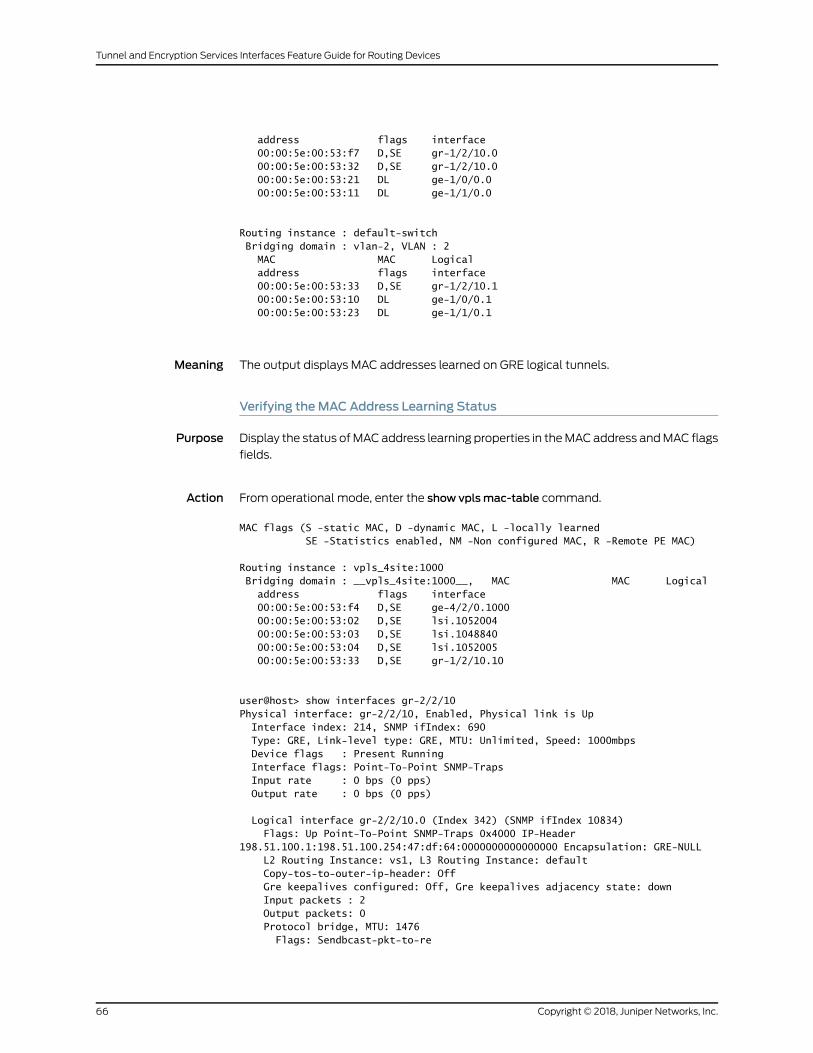
address flags interface 00:00:5e:00:53:f7 D,SE gr-1/2/10.0 00:00:5e:00:53:32 D,SE gr-1/2/10.0 00:00:5e:00:53:21 DL ge-1/0/0.0 00:00:5e:00:53:11 DL ge-1/1/0.0
Routing instance : default-switch Bridging domain : vlan-2, VLAN : 2 MAC MAC Logical address flags interface 00:00:5e:00:53:33 D,SE gr-1/2/10.1 00:00:5e:00:53:10 DL ge-1/0/0.1 00:00:5e:00:53:23 DL ge-1/1/0.1
Meaning The output displays MAC addresses learned on GRE logical tunnels.
Verifying theMACAddress Learning Status
Purpose Display the status ofMACaddress learning properties in theMACaddress andMAC flags
fields.
Action From operational mode, enter the show vplsmac-table command.
MAC flags (S -static MAC, D -dynamic MAC, L -locally learned SE -Statistics enabled, NM -Non configured MAC, R -Remote PE MAC)
Routing instance : vpls_4site:1000 Bridging domain : __vpls_4site:1000__, MAC MAC Logical address flags interface 00:00:5e:00:53:f4 D,SE ge-4/2/0.1000 00:00:5e:00:53:02 D,SE lsi.1052004 00:00:5e:00:53:03 D,SE lsi.1048840 00:00:5e:00:53:04 D,SE lsi.1052005 00:00:5e:00:53:33 D,SE gr-1/2/10.10
user@host> show interfaces gr-2/2/10 Physical interface: gr-2/2/10, Enabled, Physical link is Up Interface index: 214, SNMP ifIndex: 690 Type: GRE, Link-level type: GRE, MTU: Unlimited, Speed: 1000mbps Device flags : Present Running Interface flags: Point-To-Point SNMP-Traps Input rate : 0 bps (0 pps) Output rate : 0 bps (0 pps)
Logical interface gr-2/2/10.0 (Index 342) (SNMP ifIndex 10834) Flags: Up Point-To-Point SNMP-Traps 0x4000 IP-Header 198.51.100.1:198.51.100.254:47:df:64:0000000000000000 Encapsulation: GRE-NULL L2 Routing Instance: vs1, L3 Routing Instance: default Copy-tos-to-outer-ip-header: Off Gre keepalives configured: Off, Gre keepalives adjacency state: down Input packets : 2 Output packets: 0 Protocol bridge, MTU: 1476 Flags: Sendbcast-pkt-to-re
Copyright © 2018, Juniper Networks, Inc.66
Tunnel and Encryption Services Interfaces Feature Guide for Routing Devices
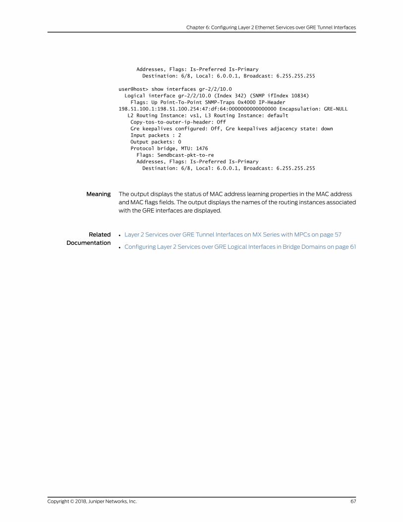
Addresses, Flags: Is-Preferred Is-Primary Destination: 6/8, Local: 6.0.0.1, Broadcast: 6.255.255.255
user@host> show interfaces gr-2/2/10.0 Logical interface gr-2/2/10.0 (Index 342) (SNMP ifIndex 10834) Flags: Up Point-To-Point SNMP-Traps 0x4000 IP-Header 198.51.100.1:198.51.100.254:47:df:64:0000000000000000 Encapsulation: GRE-NULL L2 Routing Instance: vs1, L3 Routing Instance: default Copy-tos-to-outer-ip-header: Off Gre keepalives configured: Off, Gre keepalives adjacency state: down Input packets : 2 Output packets: 0 Protocol bridge, MTU: 1476 Flags: Sendbcast-pkt-to-re Addresses, Flags: Is-Preferred Is-Primary Destination: 6/8, Local: 6.0.0.1, Broadcast: 6.255.255.255
Meaning The output displays the status of MAC address learning properties in the MAC address
andMAC flags fields. The output displays the names of the routing instances associated
with the GRE interfaces are displayed.
RelatedDocumentation
• Layer 2 Services over GRE Tunnel Interfaces on MX Series with MPCs on page 57
• Configuring Layer 2 Services over GRE Logical Interfaces in Bridge Domains on page 61
67Copyright © 2018, Juniper Networks, Inc.
Chapter 6: Configuring Layer 2 Ethernet Services over GRE Tunnel Interfaces

Copyright © 2018, Juniper Networks, Inc.68
Tunnel and Encryption Services Interfaces Feature Guide for Routing Devices
CHAPTER 7
Understanding Default PIM TunnelConfigurations
• Configuring PIM Tunnels on page 69
Configuring PIM Tunnels
PIM tunnels are enabled automatically on routers that have a tunnel PIC and on which
you enable PIM sparse mode. You do not need to configure the tunnel interface.
PIM tunnels are unidirectional.
InPIMsparsemode, the first-hop router encapsulatespacketsdestined for the rendezvous
point (RP) router. Thepackets are encapsulatedwithaunicast header andare forwarded
through a unicast tunnel to the RP. The RP then de-encapsulates the packets and
transmits them through its multicast tree. To perform the encapsulation and
de-encapsulation, the first-hop and RP routers must be equipped with Tunnel PICs.
The Junos OS creates two interfaces to handle PIM tunnels:
• pe—Encapsulatespacketsdestined for theRP.This interface is present on the first-hop
router.
• pd—De-encapsulates packets at the RP. This interface is present on the RP.
NOTE: The pe and pd interfaces do not support class-of-service (CoS)
configurations.
RelatedDocumentation
• Tunnel Services Overview on page 3
69Copyright © 2018, Juniper Networks, Inc.

Copyright © 2018, Juniper Networks, Inc.70
Tunnel and Encryption Services Interfaces Feature Guide for Routing Devices

CHAPTER 8
Facilitating VRF Table Lookup UsingVirtual Loopback Tunnel Interfaces
• Configuring Virtual Loopback Tunnels for VRF Table Lookup on page 71
• Configuring Tunnel Interfaces for Routing Table Lookup on page 73
• Example: Configuring a Virtual Loopback Tunnel for VRF Table Lookup on page 73
• Example: Virtual Routing and Forwarding (VRF) and Service Configuration on page 74
Configuring Virtual Loopback Tunnels for VRF Table Lookup
To enable egress filtering, you can either configure filtering based on the IP header, or
you can configure a virtual loopback tunnel on routers equipped with a Tunnel PIC.
Table 8 on page 71 describes eachmethod.
Table 8: Methods for Configuring Egress Filtering
CommentsConfigurationGuidelinesInterface TypeMethod
There is no restriction oncustomer-edge (CE)router-to-provider edge(PE) router interfaces.
Include the vrf-table-labelstatement at the [editrouting-instancesinstance-name] hierarchylevel.
For more information, seethe Junos OS VPNs Libraryfor Routing Devices.
NonchannelizedPoint-to-PointProtocol / HighLevel Data LinkControl(PPP/HDLC)core-facingSONET/SDHinterfaces
Filter trafficbased on the IPheader
Router must be equippedwith a Tunnel PIC.
There is no restriction onthe type of core-facinginterface used orCE router-to-PE routerinterface used.
You cannot configure avirtual loopback tunnel andthe vrf-table-labelstatement at the sametime.
See the guidelines in thissection.
All interfacesConfigure avirtual loopbacktunnelon routersequipped with aTunnel PIC
71Copyright © 2018, Juniper Networks, Inc.

Youcan configure a virtual loopback tunnel to facilitateVRF table lookupbasedonMPLS
labels. Youmight want to enable this functionality so you can do either of the following:
• Forward traffic on a PE router to CE device interface, in a sharedmedium, where the
CE device is a Layer 2 switch without IP capabilities (for example, a metro Ethernet
switch).
The first lookup is done based on the VPN label to determine which VRF table to refer
to, and the second lookup isdoneon the IPheader todeterminehowto forwardpackets
to the correct end hosts on the sharedmedium.
• Perform egress filtering at the egress PE router.
The first lookup on the VPN label is done to determinewhich VRF table to refer to, and
the second lookup is done on the IP header to determine how to filter and forward
packets. You can enable this functionality by configuring output filters on the VRF
interfaces.
To configure a virtual loopback tunnel to facilitate VRF table lookup based on MPLS
labels, you specify a virtual loopback tunnel interfacenameandassociate itwitha routing
instance that belongs to a particular routing table. The packet loops back through the
virtual loopback tunnel for route lookup. To specify a virtual loopback tunnel interface
name, youconfigure the virtual loopback tunnel interfaceat the [edit interfaces]hierarchy
level and include the family inet and family mpls statements:
vt-fpc/pic/port {unit 0 {family inet;family mpls;
}unit 1 {family inet;
}}
To associate the virtual loopback tunnel with a routing instance, include the virtual
loopback tunnel interface name at the [edit routing-instances] hierarchy level:
interface vt-fpc/pic/port;
NOTE: On virtual loopback tunnel interfaces, none of the logical interfacestatements except the family statement is supported. Note that you can
configure only inet andmpls families, and you cannot configure IPv4 or IPv6
addressesonvirtual loopback tunnel interfaces.Also, virtual loopback tunnelinterfaces do not support class-of-service (CoS) configurations.
RelatedDocumentation
Tunnel Services Overview on page 3•
• Example: Configuring a Virtual Loopback Tunnel for VRF Table Lookup on page 73
Copyright © 2018, Juniper Networks, Inc.72
Tunnel and Encryption Services Interfaces Feature Guide for Routing Devices
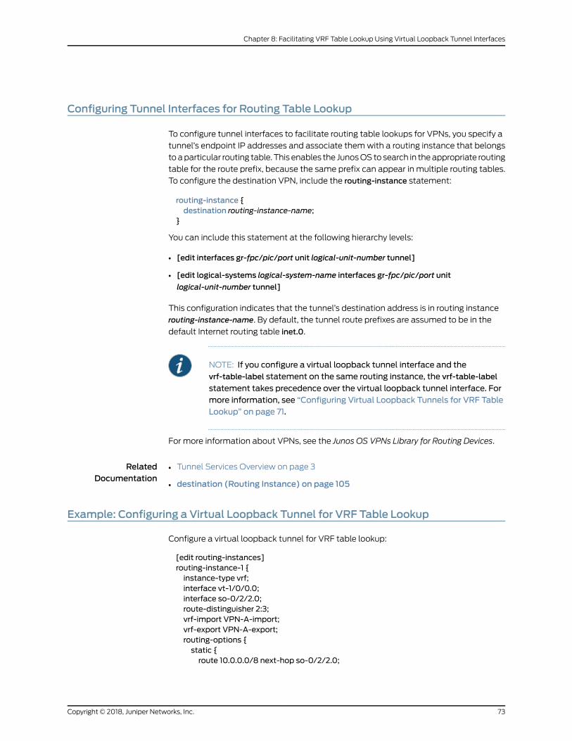
Configuring Tunnel Interfaces for Routing Table Lookup
To configure tunnel interfaces to facilitate routing table lookups for VPNs, you specify a
tunnel’s endpoint IP addresses and associate themwith a routing instance that belongs
toaparticular routing table. This enables the JunosOStosearch in theappropriate routing
table for the route prefix, because the same prefix can appear in multiple routing tables.
To configure the destination VPN, include the routing-instance statement:
routing-instance {destination routing-instance-name;
}
You can include this statement at the following hierarchy levels:
• [edit interfaces gr-fpc/pic/port unit logical-unit-number tunnel]
• [edit logical-systems logical-system-name interfaces gr-fpc/pic/port unit
logical-unit-number tunnel]
This configuration indicates that the tunnel’s destination address is in routing instance
routing-instance-name. By default, the tunnel route prefixes are assumed to be in the
default Internet routing table inet.0.
NOTE: If you configure a virtual loopback tunnel interface and thevrf-table-label statement on the same routing instance, the vrf-table-label
statement takes precedence over the virtual loopback tunnel interface. Formore information, see “Configuring Virtual Loopback Tunnels for VRF TableLookup” on page 71.
For more information about VPNs, see the Junos OS VPNs Library for Routing Devices.
RelatedDocumentation
Tunnel Services Overview on page 3•
• destination (Routing Instance) on page 105
Example: Configuring a Virtual Loopback Tunnel for VRF Table Lookup
Configure a virtual loopback tunnel for VRF table lookup:
[edit routing-instances]routing-instance-1 {instance-type vrf;interface vt-1/0/0.0;interface so-0/2/2.0;route-distinguisher 2:3;vrf-import VPN-A-import;vrf-export VPN-A-export;routing-options {static {route 10.0.0.0/8 next-hop so-0/2/2.0;
73Copyright © 2018, Juniper Networks, Inc.
Chapter 8: Facilitating VRF Table Lookup Using Virtual Loopback Tunnel Interfaces
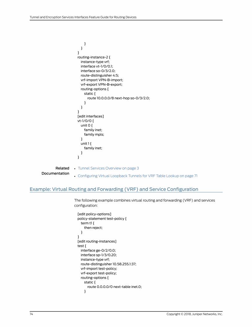
}}
}routing-instance-2 {instance-type vrf;interface vt-1/0/0.1;interface so-0/3/2.0;route-distinguisher 4:5;vrf-import VPN-B-import;vrf-export VPN-B-export;routing-options {static {route 10.0.0.0/8 next-hop so-0/3/2.0;
}}
}[edit interfaces]vt-1/0/0 {unit 0 {family inet;family mpls;
}unit 1 {family inet;
}}
RelatedDocumentation
Tunnel Services Overview on page 3•
• Configuring Virtual Loopback Tunnels for VRF Table Lookup on page 71
Example: Virtual Routing and Forwarding (VRF) and Service Configuration
The following example combines virtual routing and forwarding (VRF) and services
configuration:
[edit policy-options]policy-statement test-policy {term t1 {then reject;
}}[edit routing-instances]test {interface ge-0/2/0.0;interface sp-1/3/0.20;instance-type vrf;route-distinguisher 10.58.255.1:37;vrf-import test-policy;vrf-export test-policy;routing-options {static {route 0.0.0.0/0 next-table inet.0;
}
Copyright © 2018, Juniper Networks, Inc.74
Tunnel and Encryption Services Interfaces Feature Guide for Routing Devices

}}[edit interfaces]ge-0/2/0 {unit 0 {family inet {service {input service-set nat-me;output service-set nat-me;
}}
}}sp-1/3/0 {unit 0 {family inet;
}unit 20 {family inet;service-domain inside;
}unit 21 {family inet;service-domain outside;
}[edit services]stateful-firewall {rule allow-any-input {match-direction input;term t1 {then accept;
}}
}nat {pool hide-pool {address 10.58.16.100;port automatic;
}rule hide-all-input {match-direction input;term t1 {then {translated {source-pool hide-pool;translation-type source napt-44;
}}
}}
}service-set nat-me {stateful-firewall-rules allow-any-input;nat-rules hide-all-input;interface-service {service-interface sp-1/3/0.20;
75Copyright © 2018, Juniper Networks, Inc.
Chapter 8: Facilitating VRF Table Lookup Using Virtual Loopback Tunnel Interfaces

}}
}
Copyright © 2018, Juniper Networks, Inc.76
Tunnel and Encryption Services Interfaces Feature Guide for Routing Devices
CHAPTER 9
Enabling a VPN to Travel Through aNon-MPLS Network Using DynamicTunnels
• Configuring Dynamic Tunnels on page 77
Configuring Dynamic Tunnels
A VPN that travels through a non-MPLS network requires a GRE tunnel. This tunnel can
be either a static tunnel or a dynamic tunnel. A static tunnel is configuredmanually
between two PE routers. A dynamic tunnel is configured using BGP route resolution.
When a router receives aVPN route that resolves over a BGPnext hop that does not have
an MPLS path, a GRE tunnel can be created dynamically, allowing the VPN traffic to be
forwarded to that route. Only GRE IPv4 tunnels are supported.
To configure a dynamic tunnel between two PE routers, include the dynamic-tunnels
statement:
dynamic-tunnels tunnel-name {destination-networks prefix;source-address address;
}
You can configure this statement at the following hierarchy levels:
• [edit routing-options]
• [edit routing-instances routing-instance-name routing-options]
• [edit logical-systems logical-system-name routing-options]
• [edit logical-systems logical-system-name routing-instances routing-instance-name
routing-options]
RelatedDocumentation
• Tunnel Services Overview on page 3
• dynamic-tunnels on page 108
• Junos OS Routing Protocols Library
77Copyright © 2018, Juniper Networks, Inc.

• Junos OS VPNs Library for Routing Devices
Copyright © 2018, Juniper Networks, Inc.78
Tunnel and Encryption Services Interfaces Feature Guide for Routing Devices

PART 2
Encryption Services
• Overview on page 81
• Sending Encrypted Traffic Through Tunnels on page 83
• Configuring Redundancy in Case of Service Failure on page 91
79Copyright © 2018, Juniper Networks, Inc.

Copyright © 2018, Juniper Networks, Inc.80
Tunnel and Encryption Services Interfaces Feature Guide for Routing Devices
CHAPTER 10
Overview
• Encryption Overview on page 81
• Configuring an ES Tunnel Interface for a Layer 3 VPN on page 81
Encryption Overview
The IP Security (IPsec) architecture provides a security suite for the IP version 4 (IPv4)
and IP version 6 (IPv6) network layers. The suite provides functionality such as
authentication of origin, data integrity, confidentiality, replay protection, and
nonrepudiation of source. It also defines mechanisms for key generation and exchange,
management of security associations, and support for digital certificates.
IPsec defines a security association (SA) and key management framework that can be
used with any network layer protocol. The SA specifies what protection policy to apply
to traffic between two IP-layer entities. For more information, see the Junos OS
Administration Library. The standards are defined in the following RFCs:
• RFC 2401, Security Architecture for the Internet Protocol
• RFC 2406, IP Encapsulating Security Payload (ESP)
RelatedDocumentation
Configuring Encryption Interfaces on page 83•
• Configuring Filters for Traffic Transiting the ES PIC on page 85
• Configuring ES PIC Redundancy on page 91
• Configuring IPsec Tunnel Redundancy on page 92
Configuring an ES Tunnel Interface for a Layer 3 VPN
To configure an ES tunnel interface for a Layer 3 VPN, you need to configure an ES tunnel
interface on the provider edge (PE) router and on the customer edge (CE) router. You
also need to configure IPsec on the PE and CE routers. For more information about
configuring an ES tunnel for a Layer 3 VPN, see the Junos OS VPNs Library for Routing
Devices.
81Copyright © 2018, Juniper Networks, Inc.

RelatedDocumentation
• Encryption Overview on page 81
• Configuring Encryption Interfaces on page 83
• Configuring Filters for Traffic Transiting the ES PIC on page 85
• Configuring ES PIC Redundancy on page 91
• Configuring IPsec Tunnel Redundancy on page 92
Copyright © 2018, Juniper Networks, Inc.82
Tunnel and Encryption Services Interfaces Feature Guide for Routing Devices
CHAPTER 11
Sending Encrypted Traffic ThroughTunnels
• Configuring Encryption Interfaces on page 83
• Configuring Filters for Traffic Transiting the ES PIC on page 85
Configuring Encryption Interfaces
When you configure the encryption interface, you associate the configured SA with a
logical interface. This configuration defines the tunnel, including the logical unit, tunnel
addresses, maximum transmission unit (MTU), optional interface addresses, and the
name of the IPsec SA to apply to traffic. To configure an encryption interface, include
the following statements at the [edit interfaces es-fpc/pic/port unit logical-unit-number]
hierarchy level:
family inet {ipsec-sa ipsec-sa; # name of security association to apply to packetaddress address; # local interface address inside local VPNdestination address; # destination address inside remote VPN
}tunnel {source source-address;destination destination-address;
}
The addresses configured as the tunnel source and destination are the addresses in the
outer IP header of the tunnel.
NOTE: Youmust configure the tunnel source address locally on the router,and the tunnel destination addressmust be a valid address for the securitygateway terminating the tunnel.
The ES Physical Interface Card (PIC) is supported onM Series and T Seriesrouters.
The SAmust be a valid tunnel-mode SA. The interface address and destination address
listed are optional. The destination address allows the user to configure a static route to
83Copyright © 2018, Juniper Networks, Inc.
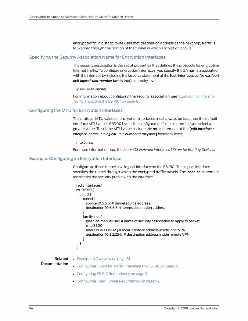
encrypt traffic. If a static route uses that destination address as the next hop, traffic is
forwarded through the portion of the tunnel in which encryption occurs.
Specifying the Security Association Name for Encryption Interfaces
The security association is the set of properties that defines the protocols for encrypting
Internet traffic. To configure encryption interfaces, you specify the SA name associated
with the interfaceby including the ipsec-sastatementat the [edit interfaceses-fpc/pic/port
unit logical-unit-number family inet] hierarchy level:
ipsec-sa sa-name;
For information about configuring the security association, see “Configuring Filters for
Traffic Transiting the ES PIC” on page 85.
Configuring theMTU for Encryption Interfaces
The protocol MTU value for encryption interfaces must always be less than the default
interface MTU value of 3900 bytes; the configuration fails to commit if you select a
greater value. To set the MTU value, include themtu statement at the [edit interfaces
interface-name unit logical-unit-number family inet] hierarchy level:
mtu bytes;
For more information, see the Junos OS Network Interfaces Library for Routing Devices.
Example: Configuring an Encryption Interface
Configure an IPsec tunnel as a logical interface on the ES PIC. The logical interface
specifies the tunnel through which the encrypted traffic travels. The ipsec-sa statement
associates the security profile with the interface.
[edit interfaces]es-0/0/0 {unit 0 {tunnel {source 10.5.5.5; # tunnel source addressdestination 10.6.6.6; # tunnel destination address
}family inet {ipsec-samanual-sa1; # name of security association to apply to packetmtu 3800;address 10.1.1.8/32 { # local interface address inside local VPNdestination 10.2.2.254; # destination address inside remote VPN
}}
}
RelatedDocumentation
Encryption Overview on page 81•
• Configuring Filters for Traffic Transiting the ES PIC on page 85
• Configuring ES PIC Redundancy on page 91
• Configuring IPsec Tunnel Redundancy on page 92
Copyright © 2018, Juniper Networks, Inc.84
Tunnel and Encryption Services Interfaces Feature Guide for Routing Devices

Configuring Filters for Traffic Transiting the ES PIC
This section contains the following topics:
• Traffic Overview on page 85
• Configuring the Security Association on page 86
• Configuring an Outbound Traffic Filter on page 87
• Applying the Outbound Traffic Filter on page 88
• Configuring an Inbound Traffic Filter on page 88
• Applying the Inbound Traffic Filter to the Encryption Interface on page 89
Traffic Overview
Traffic configuration defines the traffic that must flow through the tunnel. You configure
outbound and inbound firewall filters, which identify and direct traffic to be encrypted
and confirm that decrypted traffic parametersmatch those defined for the given tunnel.
The outbound filter is applied to the LAN orWAN interface for the incoming traffic you
want to encrypt. The inbound filter is applied to the ES PIC to check the policy for traffic
coming in from the remote host. Because of the complexity of configuring a router to
forwardpackets, noautomatic checking isdone toensure that theconfiguration is correct.
NOTE: The valid firewall filters statements for IPsec are destination-port,
source-port, protocol, destination-address, and source-address.
In Figure 4 on page 85, Gateway A protects the network 10.1.1.0/24, and Gateway B
protects the network 10.2.2.0/24. The gateways are connected by an IPsec tunnel. For
more information about firewalls, see the Routing Policies, Firewall Filters, and Traffic
Policers Feature Guide.
Figure 4: Example: IPsec Tunnel Connecting Security Gateways
The SA and ES interface for security Gateway A are configured as follows:
[edit security ipsec]security-associationmanual-sa1 {manual {direction bidirectional {protocol esp;spi 2312;authentication {algorithm hmac-md5-96;
85Copyright © 2018, Juniper Networks, Inc.
Chapter 11: Sending Encrypted Traffic Through Tunnels
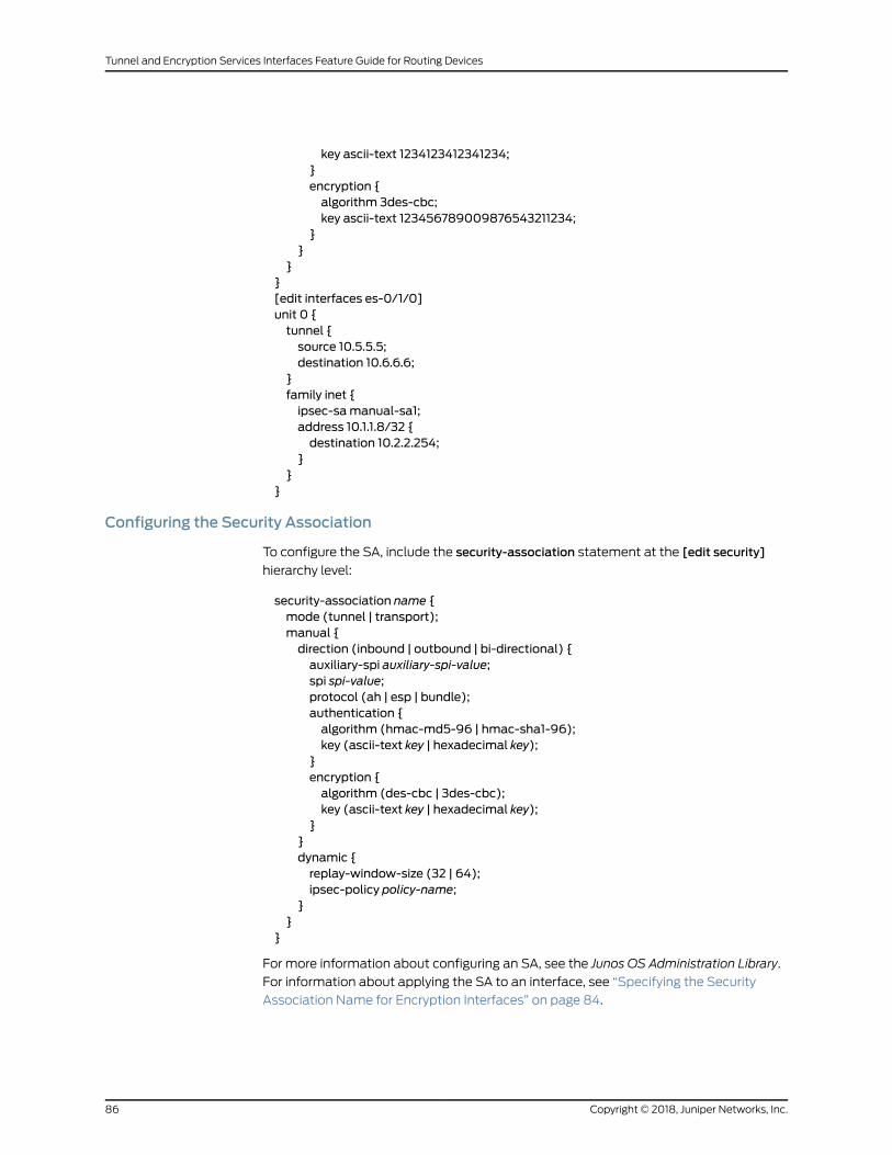
key ascii-text 1234123412341234;}encryption {algorithm 3des-cbc;key ascii-text 123456789009876543211234;
}}
}}[edit interfaces es-0/1/0]unit 0 {tunnel {source 10.5.5.5;destination 10.6.6.6;
}family inet {ipsec-samanual-sa1;address 10.1.1.8/32 {destination 10.2.2.254;
}}
}
Configuring the Security Association
To configure the SA, include the security-association statement at the [edit security]
hierarchy level:
security-association name {mode (tunnel | transport);manual {direction (inbound | outbound | bi-directional) {auxiliary-spi auxiliary-spi-value;spi spi-value;protocol (ah | esp | bundle);authentication {algorithm (hmac-md5-96 | hmac-sha1-96);key (ascii-text key | hexadecimal key);
}encryption {algorithm (des-cbc | 3des-cbc);key (ascii-text key | hexadecimal key);
}}dynamic {replay-window-size (32 | 64);ipsec-policy policy-name;
}}
}
For more information about configuring an SA, see the Junos OS Administration Library.
For information about applying the SA to an interface, see “Specifying the Security
Association Name for Encryption Interfaces” on page 84.
Copyright © 2018, Juniper Networks, Inc.86
Tunnel and Encryption Services Interfaces Feature Guide for Routing Devices

Configuring an Outbound Traffic Filter
To configure the outbound traffic filter, include the filter statement at the [edit firewall]
hierarchy level:
filter filter-name {term term-name {from {match-conditions;
}then {action;action-modifiers;
}}
}
Formore information, see theRouting Policies, Firewall Filters, and Traffic Policers Feature
Guide.
Example: Configuring an Outbound Traffic Filter
Firewall filters for outbound traffic direct the traffic through the desired IPsec tunnel and
ensure that the tunneled traffic goes out the appropriate interface (see
Figure 4 on page 85). Here, an outbound firewall filter is created on security Gateway A;
it identifies the traffic to be encrypted and adds it to the input side of the interface that
carries the internal virtual private network (VPN) traffic:
[edit firewall]filter ipsec-encrypt-policy-filter {term term1 {from {source-address { # local network10.1.1.0/24;
}destination-address { # remote network10.2.2.0/24;
}}then ipsec-samanual-sa1; # apply SA name to packetterm default {then accept;
}
NOTE: The source address, port, and protocol on the outbound traffic filtermustmatch thedestinationaddress, port, andprotocolon the inbound trafficfilter. The destination address, port, and protocol on the outbound trafficfiltermustmatch thesourceaddress, port, andprotocolon the inboundtrafficfilter.
87Copyright © 2018, Juniper Networks, Inc.
Chapter 11: Sending Encrypted Traffic Through Tunnels

Applying the Outbound Traffic Filter
After you have configured the outbound firewall filter, you apply it by including the filter
statement at the [edit interfaces interface-name unit logical-unit-number family inet]
hierarchy level:
filter {input filter-name;
}
Example: Applying the Outbound Traffic Filter
Apply the outbound traffic filter. The outbound filter is applied on the Fast Ethernet
interface at the [edit interfaces fe-0/0/1 unit 0 family inet] hierarchy level. Any packet
matching the IPsec action term (term 1) on the input filter (ipsec-encrypt-policy-filter),
configured on the Fast Ethernet interface, is directed to the ES PIC interface at the [edit
interfaces es-0/1/0 unit 0 family inet] hierarchy level. So, if a packet arrives from the
source address 10.1.1.0/24 and goes to the destination address 10.2.2.0/24, the Packet
Forwarding Engine directs the packet to the ES PIC interface, which is configured with
themanual-sa1SA.TheESPIC receives thepacket, applies themanual-sa1SA, and sends
the packet through the tunnel.
The router must have a route to the tunnel end point; add a static route if necessary.
[edit interfaces]fe-0/0/1 {unit 0 {family inet {filter {input ipsec-encrypt-policy-filter;
}address 10.1.1.254/24;
}}
}
Configuring an Inbound Traffic Filter
To configure an inbound traffic filter, include the filter statement at the [edit firewall]
hierarchy level:
filter filter-name {term term-name {from {match-conditions;
}then {action;action-modifiers;
}}
}
Copyright © 2018, Juniper Networks, Inc.88
Tunnel and Encryption Services Interfaces Feature Guide for Routing Devices
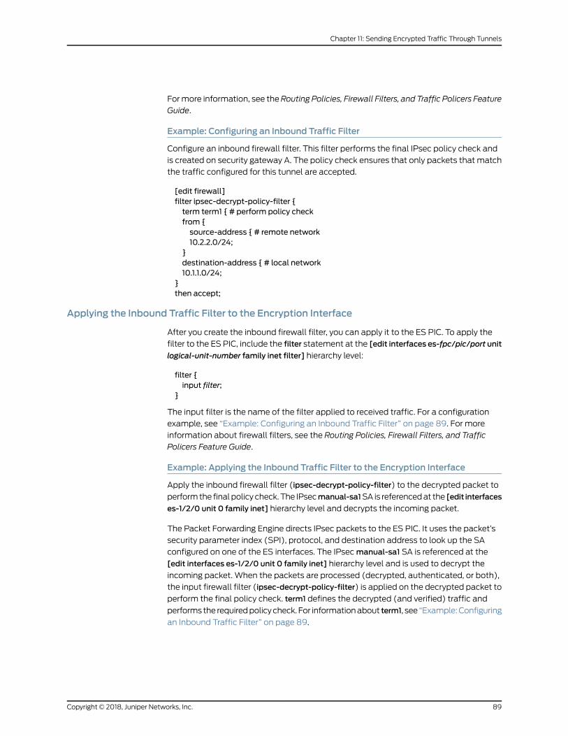
Formore information, see theRouting Policies, Firewall Filters, and Traffic Policers Feature
Guide.
Example: Configuring an Inbound Traffic Filter
Configure an inbound firewall filter. This filter performs the final IPsec policy check and
is created on security gateway A. The policy check ensures that only packets that match
the traffic configured for this tunnel are accepted.
[edit firewall]filter ipsec-decrypt-policy-filter {term term1 { # perform policy checkfrom {source-address { # remote network10.2.2.0/24;
}destination-address { # local network10.1.1.0/24;
}then accept;
Applying the Inbound Traffic Filter to the Encryption Interface
After you create the inbound firewall filter, you can apply it to the ES PIC. To apply the
filter to the ES PIC, include the filter statement at the [edit interfaces es-fpc/pic/port unit
logical-unit-number family inet filter] hierarchy level:
filter {input filter;
}
The input filter is the name of the filter applied to received traffic. For a configuration
example, see “Example: Configuring an Inbound Traffic Filter” on page 89. For more
information about firewall filters, see the Routing Policies, Firewall Filters, and Traffic
Policers Feature Guide.
Example: Applying the Inbound Traffic Filter to the Encryption Interface
Apply the inbound firewall filter (ipsec-decrypt-policy-filter) to the decrypted packet to
performthe finalpolicy check.The IPsecmanual-sa1SA is referencedat the [edit interfaces
es-1/2/0 unit 0 family inet] hierarchy level and decrypts the incoming packet.
The Packet Forwarding Engine directs IPsec packets to the ES PIC. It uses the packet’s
security parameter index (SPI), protocol, and destination address to look up the SA
configured on one of the ES interfaces. The IPsecmanual-sa1 SA is referenced at the
[edit interfaces es-1/2/0 unit 0 family inet] hierarchy level and is used to decrypt the
incoming packet. When the packets are processed (decrypted, authenticated, or both),
the input firewall filter (ipsec-decrypt-policy-filter) is applied on the decrypted packet to
perform the final policy check. term1 defines the decrypted (and verified) traffic and
performs the requiredpolicycheck. For informationabout term1, see “Example:Configuring
an Inbound Traffic Filter” on page 89.
89Copyright © 2018, Juniper Networks, Inc.
Chapter 11: Sending Encrypted Traffic Through Tunnels

NOTE: The inbound traffic filter is applied after the ES PIC has processedthe packet, so the decrypted traffic is defined as any traffic that the remotegateway is encrypting and sending to this router. IKE uses this filter todetermine the policy required for a tunnel. This policy is used during thenegotiation with the remote gateway to find thematching SA configuration.
[edit interfaces]es-1/2/0 {unit 0 {tunnel {source 10.5.5.5; # tunnel source addressdestination 10.6.6.6; # tunnel destination address
}family inet {filter {input ipsec-decrypt-policy-filter;
}ipsec-samanual-sa1; # SA name applied to packetaddress 10.1.1.8/32 { # local interface address inside local VPNdestination 10.2.2.254; # destination address inside remote VPN
}}
}
RelatedDocumentation
• Encryption Overview on page 81
• Configuring Encryption Interfaces on page 83
• Configuring ES PIC Redundancy on page 91
• Configuring IPsec Tunnel Redundancy on page 92
Copyright © 2018, Juniper Networks, Inc.90
Tunnel and Encryption Services Interfaces Feature Guide for Routing Devices
CHAPTER 12
ConfiguringRedundancy inCaseofServiceFailure
• Configuring ES PIC Redundancy on page 91
• Configuring IPsec Tunnel Redundancy on page 92
Configuring ES PIC Redundancy
You can configure ESPIC redundancy onMSeries andTSeries routers that havemultiple
ES PICs. With ES PIC redundancy, one ES PIC is active and another ES PIC is on standby.
When the primary ES PIC has a servicing failure, the backup becomes active, inherits all
the tunnels and SAs, and acts as the new next hop for IPsec traffic. Reestablishment of
tunnels on the backup ES PIC does not require new Internet Key Exchange (IKE)
negotiations. If the primary ES PIC comes online, it remains in standby and does not
preempt the backup. To determine which PIC is currently active, use the show ipsec
redundancy command.
NOTE: ES PIC redundancy is supported onM Series and T Series routers.
To configure an ES PIC as the backup, include the backup-interface statement at the
[edit interfaces fpc/pic/port es-options] hierarchy level:
backup-interface es-fpc/pic/port;
Example: Configuring ES PIC Redundancy
After youcreate the inbound firewall filter, apply it to themaster ESPIC.Here, the inbound
firewall filter (ipsec-decrypt-policy-filter) is applied on the decrypted packet to perform
the final policy check. The IPsecmanual-sa1 SA is referenced at the [edit interfaces
es-1/2/0unit0family inet]hierarchy level anddecrypts the incomingpacket. This example
does not show SA and filter configuration. For information about SA and filter
configuration, see the JunosOSAdministration Library, theRoutingPolicies, Firewall Filters,
and Traffic Policers Feature Guide, and “Example: Configuring an Inbound Traffic Filter”
on page 89.
[edit interfaces]es-1/2/0 {es-options {
91Copyright © 2018, Juniper Networks, Inc.
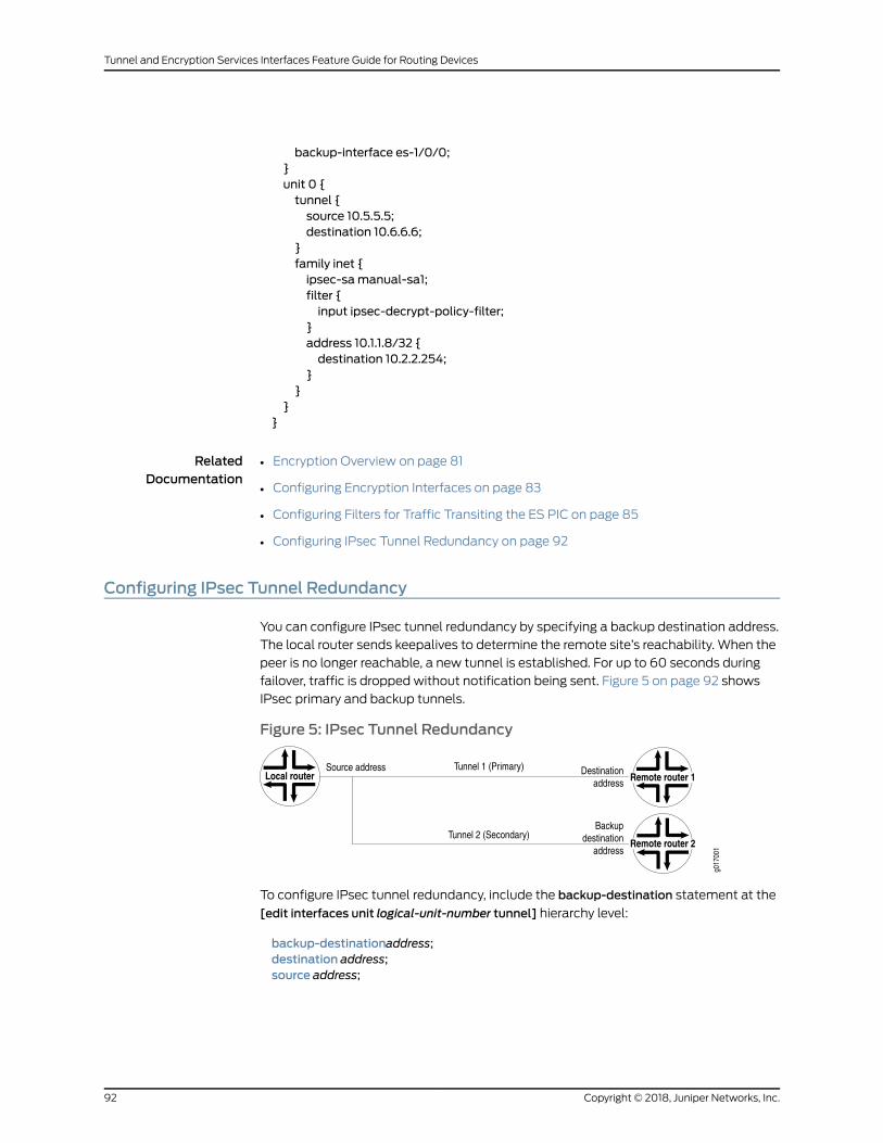
backup-interface es-1/0/0;}unit 0 {tunnel {source 10.5.5.5;destination 10.6.6.6;
}family inet {ipsec-samanual-sa1;filter {input ipsec-decrypt-policy-filter;
}address 10.1.1.8/32 {destination 10.2.2.254;
}}
}}
RelatedDocumentation
Encryption Overview on page 81•
• Configuring Encryption Interfaces on page 83
• Configuring Filters for Traffic Transiting the ES PIC on page 85
• Configuring IPsec Tunnel Redundancy on page 92
Configuring IPsec Tunnel Redundancy
You can configure IPsec tunnel redundancy by specifying a backup destination address.
The local router sends keepalives to determine the remote site’s reachability. When the
peer is no longer reachable, a new tunnel is established. For up to 60 seconds during
failover, traffic is dropped without notification being sent. Figure 5 on page 92 shows
IPsec primary and backup tunnels.
Figure 5: IPsec Tunnel Redundancy
To configure IPsec tunnel redundancy, include the backup-destination statement at the
[edit interfaces unit logical-unit-number tunnel] hierarchy level:
backup-destinationaddress;destination address;source address;
Copyright © 2018, Juniper Networks, Inc.92
Tunnel and Encryption Services Interfaces Feature Guide for Routing Devices
NOTE: Tunnel redundancy is supported onM Series and T Series routers.
The primary and backup destinationsmust be on different routers.
The tunnels must be distinct from each other and policies must match.
For more information about tunnels, see “Tunnel Interface Configuration on MX Series
Routers Overview” on page 6.
RelatedDocumentation
• Encryption Overview on page 81
• Configuring Encryption Interfaces on page 83
• Configuring Filters for Traffic Transiting the ES PIC on page 85
• Configuring ES PIC Redundancy on page 91
93Copyright © 2018, Juniper Networks, Inc.
Chapter 12: Configuring Redundancy in Case of Service Failure

Copyright © 2018, Juniper Networks, Inc.94
Tunnel and Encryption Services Interfaces Feature Guide for Routing Devices
PART 3
Configuration Statements andOperational Commands
• Configuration Statements on page 97
• Operational Commands on page 131
95Copyright © 2018, Juniper Networks, Inc.

Copyright © 2018, Juniper Networks, Inc.96
Tunnel and Encryption Services Interfaces Feature Guide for Routing Devices
CHAPTER 13
Configuration Statements
• address (Interfaces) on page 98
• allow-fragmentation on page 99
• apply-groups-except on page 100
• backup-destination on page 100
• backup-interface on page 101
• clear-dont-fragment-bit (Interfaces GRE Tunnels) on page 102
• copy-tos-to-outer-ip-header on page 103
• core-facing on page 103
• destination (Interfaces) on page 104
• destination (Routing Instance) on page 105
• destination (Tunnel Remote End) on page 105
• destination-networks on page 106
• do-not-fragment on page 107
• dynamic-tunnels on page 108
• es-options on page 109
• family on page 110
• family bridge on page 111
• family bridge (GRE Interfaces) on page 112
• filter on page 113
• hold-time (OAM) on page 114
• interfaces on page 114
• ipsec-sa on page 115
• keepalive-time on page 116
• key on page 117
• multicast-only on page 117
• peer-unit on page 118
• peer-certificate-type on page 118
• reassemble-packets on page 119
97Copyright © 2018, Juniper Networks, Inc.
• redundancy-group (Interfaces) on page 120
• redundancy-group (Chassis - MX Series) on page 121
• routing-instance on page 122
• routing-instances on page 123
• routing-options on page 124
• source on page 124
• source on page 125
• source-address on page 126
• ttl on page 126
• tunnel on page 127
• tunnel on page 128
• unit (Interfaces) on page 129
• unit (Interfaces) on page 130
address (Interfaces)
Syntax address address {destination address;
}
Hierarchy Level [edit interfaces interface-name unit logical-unit-number family family]
Release Information Statement introduced before Junos OS Release 7.4.
Description Configure the interface address.
Options address—Address of the interface.
The remaining statement is explained separately. See CLI Explorer.
Required PrivilegeLevel
interface—To view this statement in the configuration.
interface-control—To add this statement to the configuration.
RelatedDocumentation
• Configuring Encryption Interfaces on page 83
Copyright © 2018, Juniper Networks, Inc.98
Tunnel and Encryption Services Interfaces Feature Guide for Routing Devices
allow-fragmentation
Syntax allow-fragmentation;
Hierarchy Level [edit interfaces gr-fpc/pic/port unit logical-unit-number tunnel],[edit logical-systems logical-system-name interfacesgr-fpc/pic/portunit logical-unit-numbertunnel]
Release Information Statement introduced in Junos OS Release 9.2.
Statement introduced in Junos OS Release 15.1X53-D10 for QFX10000 switches.
Description For a generic routing encapsulation (GRE) tunnel, enable fragmentation of
GRE-encapsulated packets whose size exceeds the maximum transmission unit (MTU)
value of a link that the packet passes through. The don’t-fragment (DF) bit is not set in
the outer IP header of GRE-encapsulated packets.
To enable the reassembly of fragmented GRE-encapsulated packets on GRE tunnel
interfacesat theendpoint of theGRE tunnel, include the reassemble-packets statementfor the interface.
Default If you do not include the allow-fragmentation statement, fragmentation of
GRE-encapsulated packets is disabled.
Required PrivilegeLevel
interface—To view this statement in the configuration.
interface-control—To add this statement to the configuration.
RelatedDocumentation
• reassemble-packets on page 119
• Enabling Fragmentation and Reassembly on Packets After GRE-Encapsulation on
page 33
• Junos OS Services Interfaces Library for Routing Devices
99Copyright © 2018, Juniper Networks, Inc.
Chapter 13: Configuration Statements
apply-groups-except
Syntax apply-groups-except values;
Hierarchy Level [edit interfaces]
Release Information Statement introduced in Junos OS Release 15.1.
Description Disable inheritance of a configuration group.
Options value—.
Required PrivilegeLevel
configure—To enter configuration mode, but other required privilege levels depend on
where the statement is located in the configuration hierarchy.
RelatedDocumentation
• groups
• Disabling Inheritance of a Junos OS Configuration Group
• Tunnel Services Overview on page 3
• Tunnel Interface Configuration on MX Series Routers Overview on page 6
backup-destination
Syntax backup-destination destination-address;
Hierarchy Level [edit interfaces interface-name unit logical-unit-number tunnel],[edit logical-systemslogical-system-name interfaces interface-name unit logical-unit-number tunnel]
Release Information Statement introduced before Junos OS Release 7.4.
Statement introduced in Junos OS Release 15.1X53-D10 for QFX10000 switches.
Description For tunnel interfaces, specify the remote address of the backup tunnel.
Options destination-address—Address of the remote side of the connection.
Required PrivilegeLevel
interface—To view this statement in the configuration.
interface-control—To add this statement to the configuration.
RelatedDocumentation
• destination (Interfaces) on page 104
• destination (Tunnel Remote End) on page 105
• Configuring IPsec Tunnel Redundancy on page 92
Copyright © 2018, Juniper Networks, Inc.100
Tunnel and Encryption Services Interfaces Feature Guide for Routing Devices
backup-interface
Syntax backup-interface interface-name;
Hierarchy Level [edit interfaces interface-name es-options]
Release Information Statement introduced before Junos OS Release 7.4.
Description Configure a backup ES Physical Interface Card (PIC). When the primary ES PIC has a
servicing failure, the backup becomes active, inherits all the tunnels and security
associations (SAs), and acts as the new next hop for IPsec traffic.
Options interface-name—Name of ES interface to serve as the backup.
Required PrivilegeLevel
interface—To view this statement in the configuration.
interface-control—To add this statement to the configuration.
RelatedDocumentation
• Configuring ES PIC Redundancy on page 91
101Copyright © 2018, Juniper Networks, Inc.
Chapter 13: Configuration Statements
clear-dont-fragment-bit (Interfaces GRE Tunnels)
Syntax clear-dont-fragment-bit;
Hierarchy Level [edit interfaces gr-fpc/pic/port unit logical-unit-number],[edit logical-systems logical-system-name interfacesgr-fpc/pic/portunit logical-unit-number]
Release Information Statement introduced before Junos OS Release 7.4.
Statement introduced in 10.0R2 for 16x10GEMPC
Statement introduced in 13.2R4 for Multiservices MPC
Statement introduced in Junos OS Release 10.2 for MPC1 and MPC1Q.
Statement introduced in Junos OS Release 10.1 for MPC2 and variants.
Statement introduced in Junos OS Release 11.2R4 for MPC1E and MPC1E Q.
Statement introduced in Junos OS Release 11.2R4 for MPC2E and variants
Statement introduced in Junos OS Release 12.1 for MPC3E and variants
Statement introduced in Junos OS Release 12.2 for MPC2E P
Statement introduced in Junos OS Release 12.3R2 for MPC4E and variants
Statement introduced in Junos OS Release 13.3R2 and later for MPC5E and variants
Statement introduced in Junos OS Release 14.1R4, 14.2R3 and Junos Continuity 15.1 for
MPC2E NG and variants
Statement introduced in Junos OS Release 14.1R4, 14.2R3 and Junos Continuity 15.1 for
MPC3E NG and variants
Statement introduced in Junos OS Release 15.1F4 with Junos Continuity and 16.1R1 and
later for MPC7E and variants
Statement introduced in Junos OS Release 15.1F7 for MPC6E
Statement introduced in Junos OS Release 15.1F7 for MPC8E
Statement introduced in Junos OS Release 15.1F7 for MPC9E
Statement introduced in Junos OS Release 17.3 for MX10003MPC (Multi-Rate)
Description Clear the Don’t Fragment (DF) bit on all IP version 4 (IPv4) packets entering the generic
routingencapsulation (GRE) tunnel onAdaptiveServices (AS)orMultiservices interfaces.
If the encapsulated packet size exceeds the tunnel maximum transmission unit (MTU),
the packet is fragmented before encapsulation. The statement is supported only on MX
Series routers and all M Series routers except the M320 router.
Whenyouconfigure the clear-dont-fragment-bit statementonan interfacewith theMPLS
protocol family enabled, youmust specify an MTU value. This MTU value must not be
greater thanmaximum supported value, which is 9192.
Required PrivilegeLevel
interface—To view this statement in the configuration.
interface-control—To add this statement to the configuration.
RelatedDocumentation
• Enabling Fragmentation on GRE Tunnels on page 25
Copyright © 2018, Juniper Networks, Inc.102
Tunnel and Encryption Services Interfaces Feature Guide for Routing Devices

copy-tos-to-outer-ip-header
Syntax copy-tos-to-outer-ip-header;
Hierarchy Level [edit interfaces interface-name unit logical-unit-number],[edit logical-systems logical-system-name interfaces interface-nameunit logical-unit-number]
Release Information Statement introduced in Junos OS Release 8.2.
Description For GRE tunnel interfaces only, enable the inner IP header’s ToS bits to be copied to the
outer IP packet header.
To verify that this option is enabled at the interface level, use the show interfaces
interface-name detail command.
Default If you omit this statement, the ToS bits in the outer IP header are set to 0.
Required PrivilegeLevel
interface—To view this statement in the configuration.
interface-control—To add this statement to the configuration.
RelatedDocumentation
• Configuring a GRE Tunnel to Copy ToS Bits to the Outer IP Header on page 33
core-facing
Syntax core-facing;
Hierarchy Level [edit interfaces interface-name unit logical-unit-number family family],
Release Information Statement introduced in Junos OS Release 15.1.
Description Specifies that the VLAN is physically connected to a core-facing ISP router and ensures
that the network does not improperly treat the interface as a client interface. When
specified, the interface is inserted into the core-facing default mesh group where traffic
from pseudowires that belong to the default mesh group is not forwarded on the
core-facing link.
Required PrivilegeLevel
routing—To view this statement in the configuration.
routing-control—To add this statement to the configuration.
RelatedDocumentation
• Junos OS Broadband Subscriber Management and Services Library
• Tunnel Services Overview on page 3
• Tunnel Interface Configuration on MX Series Routers Overview on page 6
103Copyright © 2018, Juniper Networks, Inc.
Chapter 13: Configuration Statements
destination (Interfaces)
Syntax destination address;
Hierarchy Level [edit interfaces interface-name unit logical-unit-number tunnel],[edit interfaces interface-name unit logical-unit-number family inet address address],[edit interfaces interface-name unit logical-unit-number tunnel],[edit logical-systems logical-system-name interfaces interface-nameunit logical-unit-numberfamily inet address address]
Release Information Statement introduced before Junos OS Release 7.4.
Description For CoS on ATM interfaces, specify the remote address of the connection.
For point-to-point interfaces only, specify the address of the interface at the remote end
of the connection.
For tunnel and encryption interfaces, specify the remote address of the tunnel.
Options address—Address of the remote side of the connection.
Required PrivilegeLevel
interface—To view this statement in the configuration.
interface-control—To add this statement to the configuration.
RelatedDocumentation
• Configuring Linear RED Profiles on ATM Interfaces
• Multilink and Link Services Logical Interface Configuration Overview
• Configuring Encryption Interfaces on page 83
• Configuring Traffic Sampling on MX, M and T Series Routers
• Configuring FlowMonitoring on T Series and M Series Routers and EX9200 Switches
• Configuring Unicast Tunnels on page 29
Copyright © 2018, Juniper Networks, Inc.104
Tunnel and Encryption Services Interfaces Feature Guide for Routing Devices
destination (Routing Instance)
Syntax destination routing-instance-name;
Hierarchy Level [edit interfaces interface-name unit logical-unit-number tunnel routing-instance]
Release Information Statement introduced before Junos OS Release 7.4.
Description Specify the destination routing instance that points to the routing table containing the
tunnel destination address.
Default The default Internet routing table inet.0.
Options routing-instance-name—Name of the destination routing instance.
Required PrivilegeLevel
interface—To view this statement in the configuration.
interface-control—To add this statement to the configuration.
RelatedDocumentation
• Configuring Tunnel Interfaces for Routing Table Lookup on page 73
destination (Tunnel Remote End)
Syntax destination destination-address;
Hierarchy Level [edit interfaces interface-name unit logical-unit-number tunnel],[edit logical-systems logical-system-name interfaces interface-nameunit logical-unit-numbertunnel]
Release Information Statement introduced before Junos OS Release 7.4.
Statement introduced in Junos OS Release 12.1 for EX Series switches.
Description For tunnel interfaces, specify the remote address of the tunnel.
Options destination-address—Address of the remote side of the connection.
Required PrivilegeLevel
interface—To view this statement in the configuration.
interface-control—To add this statement to the configuration.
RelatedDocumentation
• Configuring Unicast Tunnels on page 29
• Configuring Traffic Sampling on MX, M and T Series Routers
• Configuring FlowMonitoring on T Series and M Series Routers and EX9200 Switches
105Copyright © 2018, Juniper Networks, Inc.
Chapter 13: Configuration Statements
destination-networks
Syntax destination-networks prefix;
Hierarchy Level [edit logical-systems logical-system-name routing-instances routing-instance-namerouting-options dynamic-tunnels tunnel-name],
[edit logical-systems logical-system-name routing-options dynamic-tunnels tunnel-namersvp-te entry],
[edit logical-systems logical-system-name routing-options dynamic-tunnels tunnel-name],[edit routing-instances routing-instance-name routing-optionsdynamic-tunnels tunnel-name],[edit routing-instances routing-instance-name routing-optionsdynamic-tunnels tunnel-namersvp-te entry],
[edit routing-options dynamic-tunnels tunnel-name],[edit routing-options dynamic-tunnels tunnel-name rsvp-te entry]
Release Information Statement introduced before Junos OS Release 7.4.
Statement introduced in Junos OS Release 12.3 for ACX Series routers.
Description Specify the IPv4prefix range for thedestinationnetwork.Only tunnelswithin the specified
IPv4 prefix range can be created.
Options prefix—Destination prefix of the network.
Required PrivilegeLevel
routing—To view this statement in the configuration.
routing-control—To add this statement to the configuration.
RelatedDocumentation
• Configuring GRE Tunnels for Layer 3 VPNs
• Configuring Dynamic Tunnels on page 77
• Configuring RSVP Automatic Mesh
Copyright © 2018, Juniper Networks, Inc.106
Tunnel and Encryption Services Interfaces Feature Guide for Routing Devices
do-not-fragment
Syntax do-not-fragment;
Hierarchy Level [edit interfaces gr-fpc/pic/port unit logical-unit-number tunnel],[edit logical-systems logical-system-name interfacesgr-fpc/pic/portunit logical-unit-numbertunnel]
Release Information Statement introduced in Junos OS Release 9.2.
Statement introduced in Junos OS Release 15.1X53-D10 for QFX10000 switches.
Description For a generic routing encapsulation (GRE) tunnel, disable fragmentation of
GRE-encapsulatedpackets. This sets thedo-not-fragment (DF)bit in theouter IPheader
of the GRE-encapsulated packets so that they do not get fragmented anywhere in the
path.When the size of a GRE-encapsulated packet is greater than theMTU of a link that
the packet passes through, the GRE-encapsulated packet is dropped.
Default By default, fragmentation of GRE-encapsulated packets is disabled.
Required PrivilegeLevel
interface—To view this statement in the configuration.
interface-control—To add this statement to the configuration.
RelatedDocumentation
• allow-fragmentation on page 99
• reassemble-packets on page 119
• Enabling Fragmentation and Reassembly on Packets After GRE-Encapsulation on
page 33
• Junos OS Services Interfaces Library for Routing Devices
107Copyright © 2018, Juniper Networks, Inc.
Chapter 13: Configuration Statements
dynamic-tunnels
Syntax dynamic-tunnels tunnel-name {destination-networks prefix;gre;rsvp-te entry-name {destination-networks network-prefix;label-switched-path-template (Multicast) {default-template;template-name;
}}source-address address;
}
Hierarchy Level [edit logical-systems logical-system-name routing-instances routing-instance-namerouting-options],
[edit logical-systems logical-system-name routing-options],[edit routing-instances routing-instance-name routing-options],[edit routing-options]
Release Information Statement introduced before Junos OS Release 7.4.
Statement introduced in Junos OS Release 12.3 for ACX Series routers.
Description Configure a dynamic tunnel between two PE routers.
NOTE: ACX Series routers do not support the gre statement.
Options tunnel-name—Name of the dynamic tunnel.
The remaining statements are explained separately. See CLI Explorer.
Required PrivilegeLevel
routing—To view this statement in the configuration.
routing-control—To add this statement to the configuration.
RelatedDocumentation
• Example: ConfiguringaTwo-TieredVirtualizedDataCenter for LargeEnterpriseNetworks
Copyright © 2018, Juniper Networks, Inc.108
Tunnel and Encryption Services Interfaces Feature Guide for Routing Devices

es-options
Syntax es-options {backup-interface interface-name;
}
Hierarchy Level [edit interfaces interface-name]
Release Information Statement introduced before Junos OS Release 7.4.
Description On ES interfaces, configure ES interface-specific interface properties.
The backup-interface statement is explained separately.
Required PrivilegeLevel
interface—To view this statement in the configuration.
interface-control—To add this statement to the configuration.
RelatedDocumentation
• Configuring ES PIC Redundancy on page 91
109Copyright © 2018, Juniper Networks, Inc.
Chapter 13: Configuration Statements
family
Syntax family family {ipsec-sa sa-name;
}
Hierarchy Level [edit interfaces interface-name unit logical-unit-number]
Release Information Statement introduced before Junos OS Release 7.4.
Description Configure protocol family information for the logical interface.
Options family—Protocol family:
• ccc—Circuit cross-connect protocol suite
• inet—IP version 4 suite
• inet6—IP version 6 suite
• iso—OpenSystems Interconnection(OSI) InternationalOrganization forStandardization
(ISO) protocol suite
• mlfr-end-to-end—Multilink Frame Relay FRF.15
• mlfr-uni-nni—Multilink Frame Relay FRF.16
• multilink-ppp—Multilink Point-to-Point Protocol
• mpls—MPLS
• tcc—Translational cross-connect protocol suite
• tnp—Trivial Network Protocol
• vpls—Virtual private LAN service
The remaining statements are explained separately. See CLI Explorer.
Required PrivilegeLevel
interface—To view this statement in the configuration.
interface-control—To add this statement to the configuration.
RelatedDocumentation
• Configuring Encryption Interfaces on page 83
• Junos OS Network Interfaces Library for Routing Devices for other statements that do
not affect services interfaces.
Copyright © 2018, Juniper Networks, Inc.110
Tunnel and Encryption Services Interfaces Feature Guide for Routing Devices

family bridge
Syntax family bridge {apply-groups value;apply-groups-except value;core-facing;interface-mode access | trunk;inner-vlan-id-list inner-vlan-id-range;storm-control;vlan-id vlan-id ;vlan-id-list vlan-id-range;
}
Hierarchy Level [edit interfaces][edit logical-systems name interfaces]
Release Information Statement introduced in Junos OS Release 15.1.
Starting in Junos OS release 17.4R1 for MX Series routers, support for storm control was
added for logical systems.
Description Family bridge is used when you want a port that has more than one logical unit, each
with the same or different encapsulations. Bridge domains are associated with GRE
interface with the corresponding BD VLAN.
Options The remaining statements are explained separately. See CLI Explorer.
Required PrivilegeLevel
system—To view this statement in the configuration.
interface-control—To add this statement to the configuration.
RelatedDocumentation
• Tunnel Services Overview on page 3
• Tunnel Interface Configuration on MX Series Routers Overview on page 6
111Copyright © 2018, Juniper Networks, Inc.
Chapter 13: Configuration Statements

family bridge (GRE Interfaces)
Syntax family bridge {interface-mode (access | trunk);core-facing;vlan-id number;vlan-id-list vlan-list;
}
Hierarchy Level [edit interfaces gr-fpc/pic/port.unit]
Release Information Statement at the [edit interfaces gr-fpc/pic/port.unit] hierarchy level introduced in Junos
OS Release 15.1 for MX Series routers.
Description Configure thebridgedomain family onGRE interfaces. Toenable Layer 2Ethernetpackets
to be terminated on GRE tunnels, youmust configure the bridge domain protocol family
on the gr- interfaces and associate the gr- interfaces with the bridge domain. Youmust
configure the GRE interfaces as core-facing interfaces, and theymust be access or trunk
interfaces. To configure the bridge domain family on gr- interfaces, include the family
bridge statement at the [edit interfacesgr-fpc/pic/portunit logical-unit-number]hierarchy
level.
Options interface-mode—Specify the type of VLAN tagging onpackets that the interface accepts.
access—Configure a logical interface to accept untagged packets. Specify the VLAN to
which this interface belongs using the vlan-id statement.
trunk—Configure a single logical interface to accept packets tagged with any VLAN ID
specified with the vlan-id or vlan-id-list statement.
core-facing—Specify that the VLAN is physically connected to a core-facing ISP router
and ensures that the network does not improperly treat the interface as a client
interface.When specified, the interface is inserted into the core-facing defaultmesh
group where traffic from pseudowires that belong to the default mesh group is not
forwarded on the core-facing link.
vlan-id number—Individual VLAN IDs separated by a space.
vlan-id-listvlan-list—StartingVLAN IDandendingVLAN ID inan inclusive range.Separate
the starting VLAN ID and ending VLAN ID with a hyphen.
Required PrivilegeLevel
interface—To view this statement in the configuration.
interface-control—To add this statement to the configuration.
RelatedDocumentation
• Layer 2 Services over GRE Tunnel Interfaces on MX Series with MPCs on page 57
Copyright © 2018, Juniper Networks, Inc.112
Tunnel and Encryption Services Interfaces Feature Guide for Routing Devices
filter
Syntax filter {input filter-name;output filter-name;
}
Hierarchy Level [edit interfaces interface-name unit logical-unit-number family inet]
Release Information Statement introduced before Junos OS Release 7.4.
Description Define the filters to be applied on an interface.
Options input filter-name—Identifier for the input filter.
output filter-name—Identifier for the output filter.
Required PrivilegeLevel
interface—To view this statement in the configuration.
interface-control—To add this statement to the configuration.
RelatedDocumentation
• Configuring Filters for Traffic Transiting the ES PIC on page 85
113Copyright © 2018, Juniper Networks, Inc.
Chapter 13: Configuration Statements
hold-time (OAM)
Syntax hold-time seconds;
Hierarchy Level [edit protocols oam],[edit protocols oam gre-tunnel interface interface-name]
Release Information Statement introduced in Junos OS Release 10.2.
Description Length of time the originating end of a GRE tunnel waits for keepalive packets from the
other end of the tunnel before marking the tunnel as operationally down.
Options seconds—Hold-time value.
Default: 5 seconds
Range: 5 through 250 seconds
Required PrivilegeLevel
interface—To view this statement in the configuration.
interface-control—To add this statement to the configuration.
RelatedDocumentation
• GRE Keepalive Time Overview on page 21
• Configuring GRE Keepalive Time on page 22
• keepalive-time on page 116
interfaces
Syntax interfaces { ... }
Hierarchy Level [edit]
Release Information Statement introduced before Junos OS Release 7.4.
Description Configure interfaces on the router.
Default Themanagement and internal Ethernet interfaces are automatically configured. You
must configure all other interfaces.
Required PrivilegeLevel
interface—To view this statement in the configuration.
interface-control—To add this statement to the configuration.
RelatedDocumentation
• Junos OS Network Interfaces Library for Routing Devices
Copyright © 2018, Juniper Networks, Inc.114
Tunnel and Encryption Services Interfaces Feature Guide for Routing Devices
ipsec-sa
Syntax ipsec-sa sa-name;
Hierarchy Level [edit interfaces es-fpc/pic/port unit logical-unit-number family inet]
Release Information Statement introduced before Junos OS Release 7.4.
Description Specify the IP Security (IPsec) SA name associated with the interface.
Options sa-name—IPsec SA name.
Required PrivilegeLevel
interface—To view this statement in the configuration.
interface-control—To add this statement to the configuration.
RelatedDocumentation
• Configuring Encryption Interfaces on page 83
• Junos OS Administration Library
115Copyright © 2018, Juniper Networks, Inc.
Chapter 13: Configuration Statements

keepalive-time
Syntax keepalive-time seconds;
Hierarchy Level [edit protocols oam],[edit protocols oam gre-tunnel interface interface-name],[edit protocols oam gre-tunnel interface interface-name.unit-number]
Release Information Statement introduced in Junos OS Release 10.2.
Description Time difference between consecutive keepalive packets in a GRE tunnel.
NOTE: Support for GRE keepalive packets onMPC line cards becameavailable as of Junos OS Release 11.4.
Options seconds—Keepalive time value.
Default: 1 second
Range: 1 through 50 seconds
Required PrivilegeLevel
interface—To view this statement in the configuration.
interface-control—To add this statement to the configuration.
RelatedDocumentation
• GRE Keepalive Time Overview on page 21
• Configuring GRE Keepalive Time on page 22
• hold-time on page 114
Copyright © 2018, Juniper Networks, Inc.116
Tunnel and Encryption Services Interfaces Feature Guide for Routing Devices
key
Syntax key number;
Hierarchy Level [edit interfaces interface-name unit logical-unit-number tunnel],[edit logical-systems logical-system-name interfaces interface-nameunit logical-unit-numbertunnel]
Release Information Statement introduced before Junos OS Release 7.4.
Description Identifyan individual traffic flowwithina tunnel, asdefined inRFC2890,KeyandSequence
Number Extensions to GRE. On M Series and T Series routers, you can configure the GRE
interface on an Adaptive Services, Multiservices, or Tunnel PIC. On MX Series routers,
configure the interface on a Multiservices DPC.
Options number—Value of the key.
Range: 0 through 4,294,967,295
Required PrivilegeLevel
interface—To view this statement in the configuration.
interface-control—To add this statement to the configuration.
RelatedDocumentation
• Configuring a Key Number on GRE Tunnels on page 31
multicast-only
Syntax multicast-only;
Hierarchy Level [edit interfaces interface-name unit logical-unit-number family inet],[edit logical-systems logical-system-name interfaces interface-nameunit logical-unit-numberfamily inet]
Release Information Statement introduced before Junos OS Release 7.4.
Description Configure the unit and family so that the interface can transmit and receive multicast
traffic only. You can configure this property on the IP family only.
Required PrivilegeLevel
interface—To view this statement in the configuration.
interface-control—To add this statement to the configuration.
RelatedDocumentation
• Restricting Tunnels to Multicast Traffic on page 35
• tunnel on page 128
117Copyright © 2018, Juniper Networks, Inc.
Chapter 13: Configuration Statements

peer-unit
Syntax peer-unit unit-number;
Hierarchy Level [edit interfaces interface-name unit logical-unit-number],[edit logical-systems logical-system-name interfaces interface-nameunit logical-unit-number]
Release Information Statement introduced before Junos OS Release 7.4.
Description Configure a peer relationship between two logical systems.
Options unit-number—Peering logical system unit number.
Required PrivilegeLevel
interface—To view this statement in the configuration.
interface-control—To add this statement to the configuration.
RelatedDocumentation
• Configuring Logical Tunnel Interfaces on page 37
peer-certificate-type
Syntax peer-certificate-type (pkcs7 | x509-signature);
Hierarchy Level [edit services ipsec-vpn ike policy policy-name]
Release Information Statement introduced in Release 15.1 for MX Series routers.
Description (MX Series routers only) Specify a preferred type of certificate (PKCS7 or X509). By
default, X509 encoding format is used. With the flexibility to configure the encoding
format in which certificate requests are sent to the peer, you can determine the type of
certificate to be used depending on the type supported by the peer. For example, if the
peerdoesnot supportPKCS7, certificateauthenticationcannotoccurunless youconfigure
the same type on MX Series routers as the initiator or sender.
Options • pkcs7—Public-Key Cryptography Standard #7.
• x509-signature—X509 is an ITU-T standard for public key infrastructure.
Required PrivilegeLevel
system—To view this statement in the configuration.
system-control—To add this statement to the configuration.
RelatedDocumentation
• Configuring IKE Policies
Copyright © 2018, Juniper Networks, Inc.118
Tunnel and Encryption Services Interfaces Feature Guide for Routing Devices

reassemble-packets
Syntax reassemble-packets;
Hierarchy Level [edit interfaces gr-fpc/pic/port unit logical-unit-number],[edit logical-systems logical-system-name interfacesgr-fpc/pic/portunit logical-unit-number]
Release Information Statement introduced in Junos OS Release 9.2.
Description Enable reassembly of fragmented generic routing encapsulation (GRE) encapsulated
packets on GRE tunnel interfaces at the endpoint of the GRE tunnel.
GRE-encapsulated packets are fragmented if the allow-fragmentation statement isconfigured for the GRE tunnel and the size of the GRE-encapsulated packet exceeds the
maximum transmission unit (MTU) value of a link that the packet passes through.
Default If you do not include the reassemble-packets statement, the GRE tunnel interface does
not reassemble fragmented GRE-encapsulated packets.
Required PrivilegeLevel
interface—To view this statement in the configuration.
interface-control—To add this statement to the configuration.
RelatedDocumentation
• Enabling Fragmentation and Reassembly on Packets After GRE-Encapsulation on
page 33
119Copyright © 2018, Juniper Networks, Inc.
Chapter 13: Configuration Statements

redundancy-group (Interfaces)
Syntax redundancy-group {member-interface interface-name {(active | backup);
}}
Hierarchy Level [edit interfaces interface-name]
Release Information Statement introduced in Junos OS Release 13.3.
Description Configure member tunnels of redundant logical or virtual tunnels only on MX Series 3D
Universal Edge Routers.
Options active—Set the interface to the active mode.
backup—Set the interface to the backupmode.
The remaining statement is explained separately. See CLI Explorer.
Required PrivilegeLevel
interface—To view this statement in the configuration.
interface-control—To view this statement in the configuration.
RelatedDocumentation
• Redundant Virtual Tunnels Providing Resiliency in Delivering Multicast Traffic Overview
• ConfiguringRedundantVirtual Tunnels toProvideResiliency inDeliveringMulticast Traffic
• Example: Configuring Redundant Virtual Tunnels to Provide Resiliency in Delivering
Multicast Traffic
• Example: Configuring Redundant Logical Tunnels on page 45
• Configuring Redundant Logical Tunnels on page 44
• Redundant Logical Tunnels Overview on page 41
• redundancy-group on page 121
Copyright © 2018, Juniper Networks, Inc.120
Tunnel and Encryption Services Interfaces Feature Guide for Routing Devices
redundancy-group (Chassis - MX Series)
Syntax redundancy-group {interface-type {redundant-logical-tunnel {device count;
}redundant-virtual-tunnel {device count;
}}
}
Hierarchy Level [edit chassis]
Release Information Statement introduced in Junos OS Release 13.3.
Description Configure redundant logical tunnels, redundant virtual tunnels, or both on MX Series 3D
Universal Edge Routers.
The remaining statements are explained separately. See CLI Explorer.
Required PrivilegeLevel
interface—To view this statement in the configuration.
interface-control—To add this statement to the configuration.
RelatedDocumentation
• Redundant Virtual Tunnels Providing Resiliency in Delivering Multicast Traffic Overview
• ConfiguringRedundantVirtual Tunnels toProvideResiliency inDeliveringMulticast Traffic
• Example: Configuring Redundant Virtual Tunnels to Provide Resiliency in Delivering
Multicast Traffic
• redundancy-group (Interfaces) on page 120
121Copyright © 2018, Juniper Networks, Inc.
Chapter 13: Configuration Statements
routing-instance
Syntax routing-instance {destination routing-instance-name;
}
Hierarchy Level [edit interfaces interface-name unit logical-unit-number tunnel],[edit logical-systems logical-system-name interfaces interface-nameunit logical-unit-numbertunnel]
Release Information Statement introduced before Junos OS Release 7.4.
Statement introduced in Junos OS Release 15.1X53-D10 for QFX10000 switches.
Description Specify the destination routing instance that points to the routing table containing the
tunnel destination address.
Default The default Internet routing table inet.0.
Required PrivilegeLevel
interface—To view this statement in the configuration.
interface-control—To add this statement to the configuration.
RelatedDocumentation
• Configuring Tunnel Interfaces for Routing Table Lookup on page 73
Copyright © 2018, Juniper Networks, Inc.122
Tunnel and Encryption Services Interfaces Feature Guide for Routing Devices
routing-instances
Syntax routing-instances routing-instance-name { ... }
Hierarchy Level [edit],[edit logical-systems logical-system-name]
Release Information Statement introduced before Junos OS Release 7.4.
Description Configure an additional routing entity for a router or switch. You can create multiple
instances of BGP, IS-IS, OSPF, OSPF version 3 (OSPFv3), and RIP for a router or switch.
Default Routing instances are disabled for the router or switch.
Options routing-instance-name—Name of the routing instance, a maximum of 31 characters. The
remaining statements are explained separately.
Required PrivilegeLevel
routing—To view this statement in the configuration.
routing-control—To add this statement to the configuration.
RelatedDocumentation
• Configuring EVPN Routing Instances
• Configuring Routing Instances on PE Routers in VPNs
123Copyright © 2018, Juniper Networks, Inc.
Chapter 13: Configuration Statements
routing-options
Syntax routing-options { ... }
For information on the complete list of routing-options, see the Protocol-Independent
Routing Properties Feature Guide .
Hierarchy Level [edit],[edit logical-systems logical-system-name],[edit logical-systems logical-system-name routing-instances routing-instance-name],[edit routing-instances routing-instance-name]
Release Information Statement introduced before Junos OS Release 7.4.
Statement introduced in Junos OS Release 9.0 for EX Series switches.
Description Configure protocol-independent routing properties.
Required PrivilegeLevel
routing—To view this statement in the configuration.
routing-control—To add this statement to the configuration.
RelatedDocumentation
• Protocol-Independent Routing Properties Feature Guide
source
Syntax source source-address;
Hierarchy Level [edit interfaces interface-name unit logical-unit-number family inet address address],[edit interfaces interface-name unit logical-unit-number tunnel]
Release Information Statement introduced before Junos OS Release 7.4.
Description For tunnel and encryption interfaces, specify the source address.
Options source-address—Address of the source side of the connection.
Required PrivilegeLevel
interface—To view this statement in the configuration.
interface-control—To add this statement to the configuration.
RelatedDocumentation
• Configuring Encryption Interfaces on page 83
• Configuring Traffic Sampling on MX, M and T Series Routers
• Configuring FlowMonitoring on T Series and M Series Routers and EX9200 Switches
Copyright © 2018, Juniper Networks, Inc.124
Tunnel and Encryption Services Interfaces Feature Guide for Routing Devices
source
Syntax source source-address;
Hierarchy Level [edit interfaces interface-name unit logical-unit-number tunnel]
Release Information Statement introduced before Junos OS Release 7.4.
Statement introduced in Junos OS Release 12.1 for EX Series switches.
Statement introduced in Junos OS Release 13.2 for the QFX Series.
Statement introduced in Junos OS Release 14.1X53-D20 for the OCX Series.
Description Specify the source address of the tunnel.
Default If you do not specify a source address, the tunnel uses the unit’s primary address as the
source address of the tunnel.
Options source-address—Address of the local side of the tunnel. This is the address that is placed
in the outer IP header’s source field.
Required PrivilegeLevel
interface—To view this statement in the configuration.
interface-control—To add this statement to the configuration.
RelatedDocumentation
• Tunnel Services Overview on page 3
125Copyright © 2018, Juniper Networks, Inc.
Chapter 13: Configuration Statements

source-address
Syntax source-address address;
Hierarchy Level [edit logical-systems logical-system-name routing-instances routing-instance-namerouting-options dynamic-tunnels tunnel-name],
[edit logical-systems logical-system-name routing-options dynamic-tunnels tunnel-name],[edit routing-instances routing-instance-name routing-optionsdynamic-tunnels tunnel-name],[edit routing-options dynamic-tunnels tunnel-name]
Release Information Statement introduced before Junos OS Release 7.4.
Statement introduced in Junos OS Release 12.3 for ACX Series routers.
Description Configure the tunnel source address.
Options address—Name of the source address.
Required PrivilegeLevel
routing—To view this statement in the configuration.
routing-control—To add this statement to the configuration.
RelatedDocumentation
• Configuring Dynamic Tunnels on page 77
ttl
Syntax ttl value;
Hierarchy Level [edit interfaces interface-name unit number tunnel]
Release Information Statement introduced before Junos OS Release 7.4.
Statement introduced in Junos OS Release 12.1 for EX Series switches.
Statement introduced in Junos OS Release 17.1 for ACX Series routers.
Description Set the time-to-live value bit in the header of the outer IP packet.
Options value—Time-to-live value.
Range: 0 through 255
Default: 64
Required PrivilegeLevel
interface—To view this statement in the configuration.
interface-control—To add this statement to the configuration.
RelatedDocumentation
• Tunnel Services Overview on page 3
Copyright © 2018, Juniper Networks, Inc.126
Tunnel and Encryption Services Interfaces Feature Guide for Routing Devices
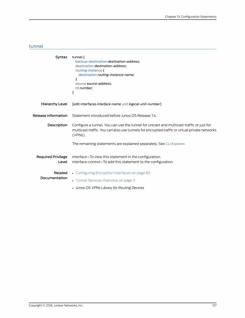
tunnel
Syntax tunnel {backup-destination destination-address;destination destination-address;routing-instance {destination routing-instance-name;
}source source-address;ttl number;
}
Hierarchy Level [edit interfaces interface-name unit logical-unit-number]
Release Information Statement introduced before Junos OS Release 7.4.
Description Configure a tunnel. You can use the tunnel for unicast andmulticast traffic or just for
multicast traffic. You can also use tunnels for encrypted traffic or virtual private networks
(VPNs).
The remaining statements are explained separately. See CLI Explorer.
Required PrivilegeLevel
interface—To view this statement in the configuration.
interface-control—To add this statement to the configuration.
RelatedDocumentation
• Configuring Encryption Interfaces on page 83
• Tunnel Services Overview on page 3
• Junos OS VPNs Library for Routing Devices
127Copyright © 2018, Juniper Networks, Inc.
Chapter 13: Configuration Statements
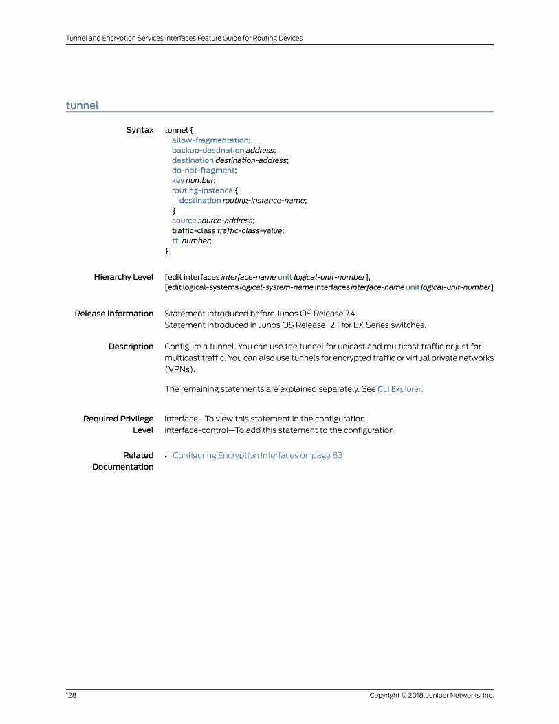
tunnel
Syntax tunnel {allow-fragmentation;backup-destination address;destination destination-address;do-not-fragment;key number;routing-instance {destination routing-instance-name;
}source source-address;traffic-class traffic-class-value;ttl number;
}
Hierarchy Level [edit interfaces interface-name unit logical-unit-number],[edit logical-systems logical-system-name interfaces interface-nameunit logical-unit-number]
Release Information Statement introduced before Junos OS Release 7.4.
Statement introduced in Junos OS Release 12.1 for EX Series switches.
Description Configure a tunnel. You can use the tunnel for unicast andmulticast traffic or just for
multicast traffic. You can also use tunnels for encrypted traffic or virtual private networks
(VPNs).
The remaining statements are explained separately. See CLI Explorer.
Required PrivilegeLevel
interface—To view this statement in the configuration.
interface-control—To add this statement to the configuration.
RelatedDocumentation
• Configuring Encryption Interfaces on page 83
Copyright © 2018, Juniper Networks, Inc.128
Tunnel and Encryption Services Interfaces Feature Guide for Routing Devices
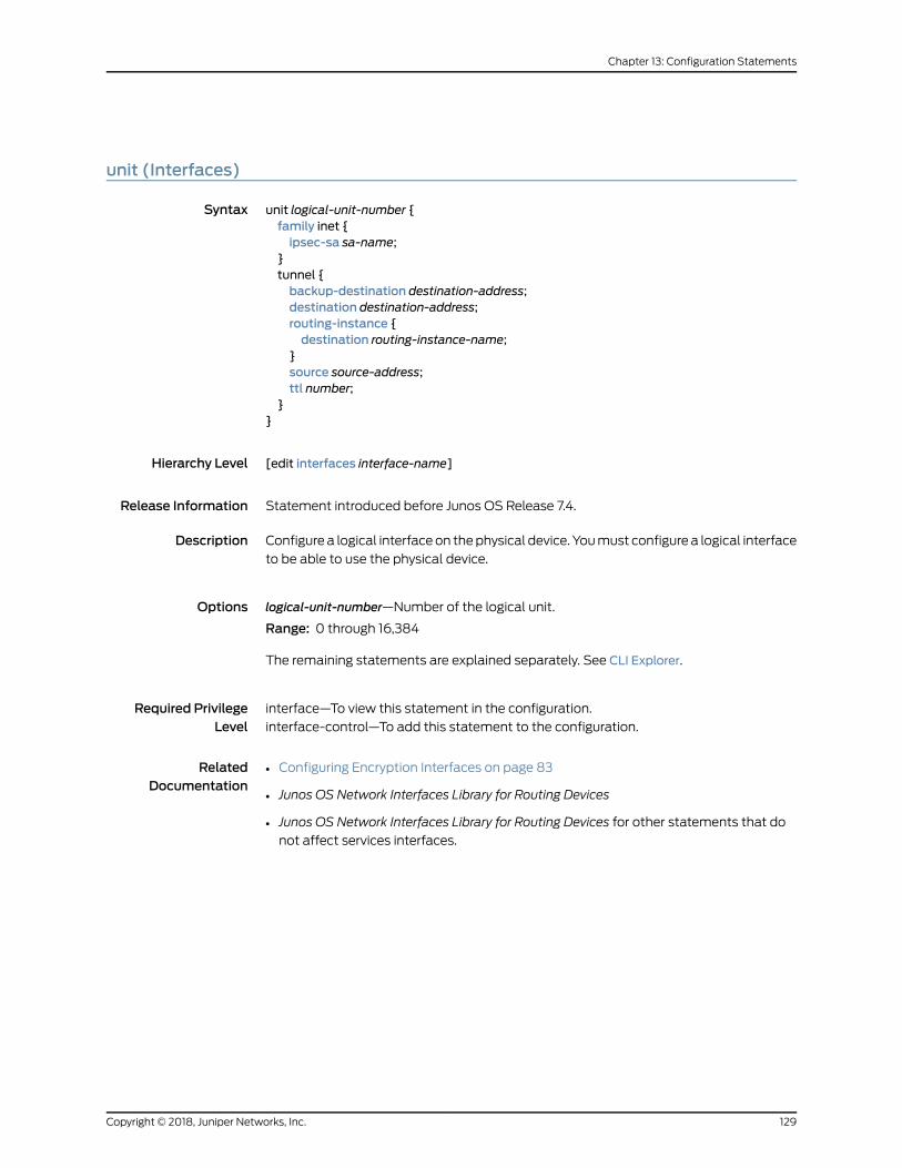
unit (Interfaces)
Syntax unit logical-unit-number {family inet {ipsec-sa sa-name;
}tunnel {backup-destination destination-address;destination destination-address;routing-instance {destination routing-instance-name;
}source source-address;ttl number;
}}
Hierarchy Level [edit interfaces interface-name]
Release Information Statement introduced before Junos OS Release 7.4.
Description Configure a logical interfaceon thephysical device. Youmust configure a logical interface
to be able to use the physical device.
Options logical-unit-number—Number of the logical unit.
Range: 0 through 16,384
The remaining statements are explained separately. See CLI Explorer.
Required PrivilegeLevel
interface—To view this statement in the configuration.
interface-control—To add this statement to the configuration.
RelatedDocumentation
• Configuring Encryption Interfaces on page 83
• Junos OS Network Interfaces Library for Routing Devices
• Junos OS Network Interfaces Library for Routing Devices for other statements that do
not affect services interfaces.
129Copyright © 2018, Juniper Networks, Inc.
Chapter 13: Configuration Statements
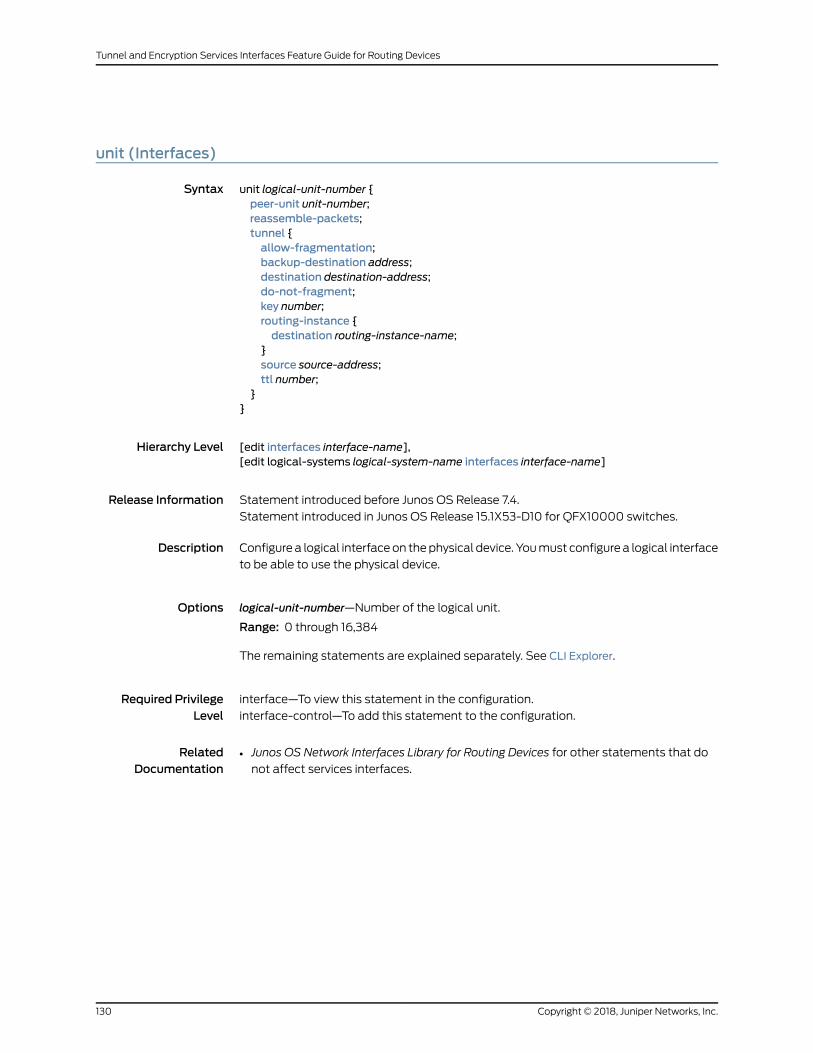
unit (Interfaces)
Syntax unit logical-unit-number {peer-unit unit-number;reassemble-packets;tunnel {allow-fragmentation;backup-destination address;destination destination-address;do-not-fragment;key number;routing-instance {destination routing-instance-name;
}source source-address;ttl number;
}}
Hierarchy Level [edit interfaces interface-name],[edit logical-systems logical-system-name interfaces interface-name]
Release Information Statement introduced before Junos OS Release 7.4.
Statement introduced in Junos OS Release 15.1X53-D10 for QFX10000 switches.
Description Configure a logical interfaceon thephysical device. Youmust configure a logical interface
to be able to use the physical device.
Options logical-unit-number—Number of the logical unit.
Range: 0 through 16,384
The remaining statements are explained separately. See CLI Explorer.
Required PrivilegeLevel
interface—To view this statement in the configuration.
interface-control—To add this statement to the configuration.
RelatedDocumentation
• Junos OS Network Interfaces Library for Routing Devices for other statements that do
not affect services interfaces.
Copyright © 2018, Juniper Networks, Inc.130
Tunnel and Encryption Services Interfaces Feature Guide for Routing Devices

CHAPTER 14
Operational Commands
• clear ike security-associations
• clear ipsec security-associations
• request ipsec switch
• request security certificate enroll (Signed)
• request security certificate enroll (Unsigned)
• request security key-pair
• request system certificate add
• show ike security-associations
• show interfaces (Encryption)
• show interfaces (GRE)
• show interfaces (IP-over-IP)
• show interfaces (Logical Tunnel)
• show interfaces (Multicast Tunnel)
• show interfaces (PIM)
• show interfaces (Virtual Loopback Tunnel)
• show ipsec certificates
• show ipsec redundancy
• show ipsec security-associations
• show system certificate
131Copyright © 2018, Juniper Networks, Inc.

clear ike security-associations
Syntax clear ike security-associations<destination-ip-address>
Release Information Command introduced before Junos OS Release 7.4.
Description (Encryption interface onM Series and T Series routers only) Clear information about the
current Internet Key Exchange (IKE) security association. This command is valid for
dynamic security associations only. For IKEv2, this command creates new security
associations for IKE SA and IPSEC SAs.
Options none—Clear all IKE security associations.
destination-ip-address—(Optional) Clear the IKE security association at the specifieddestination address.
Required PrivilegeLevel
view
RelatedDocumentation
show ike security-associations on page 141•
List of Sample Output clear ike security-associations on page 132
Output Fields When you enter this command, you are provided feedback on the status of your request.
Sample Output
clear ike security-associations
user@host> clear ike security-associations
Copyright © 2018, Juniper Networks, Inc.132
Tunnel and Encryption Services Interfaces Feature Guide for Routing Devices
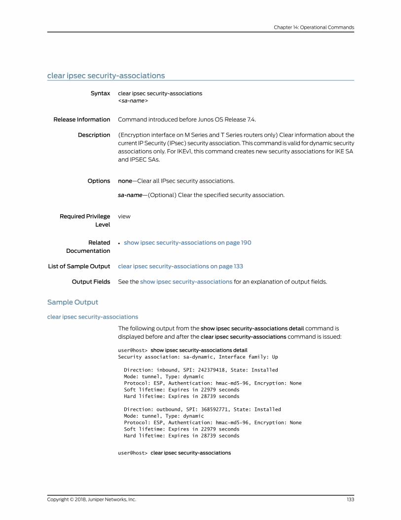
clear ipsec security-associations
Syntax clear ipsec security-associations<sa-name>
Release Information Command introduced before Junos OS Release 7.4.
Description (Encryption interface onM Series and T Series routers only) Clear information about the
current IPSecurity (IPsec) securityassociation.This command is valid fordynamicsecurity
associations only. For IKEv1, this command creates new security associations for IKE SA
and IPSEC SAs.
Options none—Clear all IPsec security associations.
sa-name—(Optional) Clear the specified security association.
Required PrivilegeLevel
view
RelatedDocumentation
show ipsec security-associations on page 190•
List of Sample Output clear ipsec security-associations on page 133
Output Fields See the show ipsec security-associations for an explanation of output fields.
Sample Output
clear ipsec security-associations
The following output from the show ipsec security-associations detail command is
displayed before and after the clear ipsec security-associations command is issued:
user@host> show ipsec security-associations detailSecurity association: sa-dynamic, Interface family: Up
Direction: inbound, SPI: 242379418, State: Installed Mode: tunnel, Type: dynamic Protocol: ESP, Authentication: hmac-md5-96, Encryption: None Soft lifetime: Expires in 22979 seconds Hard lifetime: Expires in 28739 seconds
Direction: outbound, SPI: 368592771, State: Installed Mode: tunnel, Type: dynamic Protocol: ESP, Authentication: hmac-md5-96, Encryption: None Soft lifetime: Expires in 22979 seconds Hard lifetime: Expires in 28739 seconds
user@host> clear ipsec security-associations
133Copyright © 2018, Juniper Networks, Inc.
Chapter 14: Operational Commands

user@host> show ipsec security-associations detailSecurity association: sa-dynamic, Interface family: Up
Direction: inbound, SPI: 1031597683, State: Installed Mode: tunnel, Type: dynamic Protocol: ESP, Authentication: hmac-md5-96, Encryption: None Soft lifetime: Expires in 23037 seconds Hard lifetime: Expires in 28797 seconds
Direction: outbound, SPI: 1618419878, State: Installed Mode: tunnel, Type: dynamic Protocol: ESP, Authentication: hmac-md5-96, Encryption: None Soft lifetime: Expires in 23037 seconds Hard lifetime: Expires in 28797 seconds
Copyright © 2018, Juniper Networks, Inc.134
Tunnel and Encryption Services Interfaces Feature Guide for Routing Devices

request ipsec switch
Syntax request ipsec switch (interface <es-fpc/pic/port> | security-associations <sa-name>)
Release Information Command introduced before Junos OS Release 7.4.
Command introduced in Junos OS Release 9.0 for EX Series switches.
Description (Encryption interfaceonMSeries, PTXSeries, andTSeries routers andEXSeries switches
only) Manually switch from the primary to the backup encryption services interface, or
switch from the primary to the backup IP Security (IPsec) tunnel.
Options interface <es-fpc/pic/port>—Switch to the backup encryption interface.
security-associations <sa-name>—Switch to the backup tunnel.
Required PrivilegeLevel
view
RelatedDocumentation
show ipsec redundancy on page 188•
List of Sample Output request ipsec switch security-associations on page 135
Output Fields When you enter this command, you are provided feedback on the status of your request.
Sample Output
request ipsec switch security-associations
user@host> request ipsec switch security-associations sa-private
135Copyright © 2018, Juniper Networks, Inc.
Chapter 14: Operational Commands
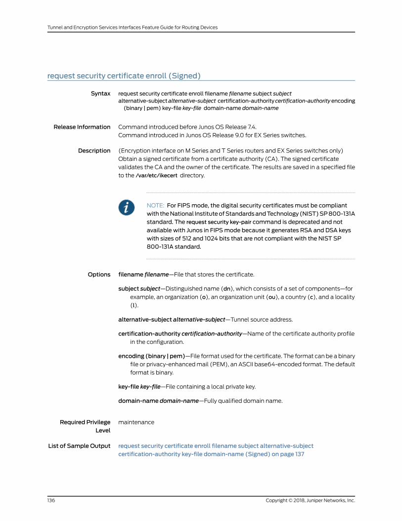
request security certificate enroll (Signed)
Syntax request security certificate enroll filename filename subject subjectalternative-subjectalternative-subject certification-authoritycertification-authorityencoding(binary | pem) key-file key-file domain-name domain-name
Release Information Command introduced before Junos OS Release 7.4.
Command introduced in Junos OS Release 9.0 for EX Series switches.
Description (Encryption interface on M Series and T Series routers and EX Series switches only)
Obtain a signed certificate from a certificate authority (CA). The signed certificate
validates the CA and the owner of the certificate. The results are saved in a specified file
to the /var/etc/ikecert directory.
NOTE: For FIPSmode, the digital security certificatesmust be compliantwith theNational InstituteofStandardsandTechnology(NIST)SP800-131Astandard. The request security key-pair command is deprecated and not
available with Junos in FIPSmode because it generates RSA and DSA keyswith sizes of 512 and 1024 bits that are not compliant with the NIST SP800-131A standard.
Options filename filename—File that stores the certificate.
subject subject—Distinguished name (dn), which consists of a set of components—forexample, an organization (o), an organization unit (ou), a country (c), and a locality
(l).
alternative-subject alternative-subject—Tunnel source address.
certification-authority certification-authority—Name of the certificate authority profilein the configuration.
encoding (binary | pem)—File format used for the certificate. The format can be a binaryfile or privacy-enhancedmail (PEM), an ASCII base64-encoded format. The default
format is binary.
key-file key-file—File containing a local private key.
domain-name domain-name—Fully qualified domain name.
Required PrivilegeLevel
maintenance
List of Sample Output request security certificate enroll filename subject alternative-subjectcertification-authority key-file domain-name (Signed) on page 137
Copyright © 2018, Juniper Networks, Inc.136
Tunnel and Encryption Services Interfaces Feature Guide for Routing Devices

Output Fields When you enter this command, you are provided feedback on the status of your request.
Sample Output
request security certificate enroll filename subject alternative-subject certification-authority key-filedomain-name (Signed)
user@host> request security certificate enroll filename host.crt subject c=uk,o=londonalternative-subject 10.50.1.4 certification-authority verisign key-file host-1.prv domain-namehost.example.comCA name: example.com CA file: ca_verisign local pub/private key pair: host.prv subject: c=uk,o=london domain name: host.example.com alternative subject: 10.50.1.4 Encoding: binary Certificate enrollment has started. To view the status of your enrollment, check the key management process (kmd) log file at /var/log/kmd. <--------------
137Copyright © 2018, Juniper Networks, Inc.
Chapter 14: Operational Commands
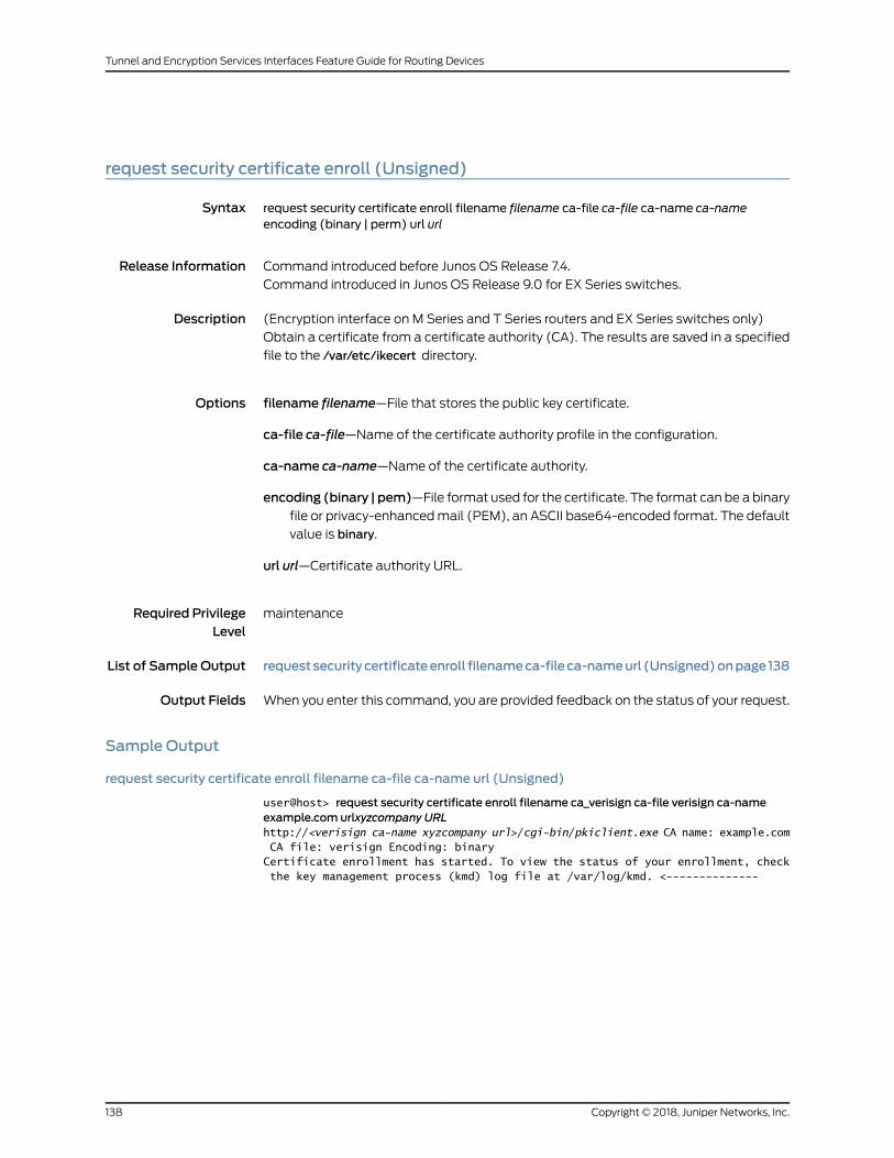
request security certificate enroll (Unsigned)
Syntax request security certificate enroll filename filename ca-file ca-file ca-name ca-nameencoding (binary | perm) url url
Release Information Command introduced before Junos OS Release 7.4.
Command introduced in Junos OS Release 9.0 for EX Series switches.
Description (Encryption interface on M Series and T Series routers and EX Series switches only)
Obtain a certificate from a certificate authority (CA). The results are saved in a specified
file to the /var/etc/ikecert directory.
Options filename filename—File that stores the public key certificate.
ca-file ca-file—Name of the certificate authority profile in the configuration.
ca-name ca-name—Name of the certificate authority.
encoding (binary | pem)—File format used for the certificate. The format can be a binaryfile or privacy-enhancedmail (PEM), an ASCII base64-encoded format. The default
value is binary.
url url—Certificate authority URL.
Required PrivilegeLevel
maintenance
List of Sample Output requestsecuritycertificateenroll filenameca-fileca-nameurl (Unsigned)onpage 138
Output Fields When you enter this command, you are provided feedback on the status of your request.
Sample Output
request security certificate enroll filename ca-file ca-name url (Unsigned)
user@host> request security certificate enroll filename ca_verisign ca-file verisign ca-nameexample.com urlxyzcompany URLhttp://<verisign ca-name xyzcompany url>/cgi-bin/pkiclient.exe CA name: example.com CA file: verisign Encoding: binary Certificate enrollment has started. To view the status of your enrollment, check the key management process (kmd) log file at /var/log/kmd. <--------------
Copyright © 2018, Juniper Networks, Inc.138
Tunnel and Encryption Services Interfaces Feature Guide for Routing Devices
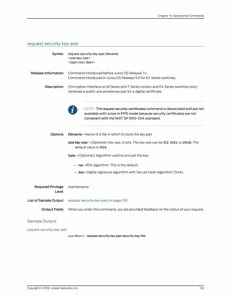
request security key-pair
Syntax request security key-pair filename<size key-size><type (rsa | dsa)>
Release Information Command introduced before Junos OS Release 7.4.
Command introduced in Junos OS Release 9.0 for EX Series switches.
Description (Encryption interface on M Series and T Series routers and EX Series switches only)
Generate a public and private key pair for a digital certificate.
NOTE: The request security-certificates command is deprecated and are not
available with Junos in FIPSmode because security certificates are notcompliant with the NIST SP 800-131A standard.
Options filename—Name of a file in which to store the key pair.
size key-size—(Optional) Key size, in bits. The key size can be 512, 1024, or 2048. Thedefault value is 1024.
type—(Optional) Algorithm used to encrypt the key:
• rsa—RSA algorithm. This is the default.
• dsa—Digital signature algorithmwith Secure Hash Algorithm (SHA).
Required PrivilegeLevel
maintenance
List of Sample Output request security key-pair on page 139
Output Fields When you enter this command, you are provided feedback on the status of your request.
Sample Output
request security key-pair
user@host> request security key-pair security-key-file
139Copyright © 2018, Juniper Networks, Inc.
Chapter 14: Operational Commands
request system certificate add
Syntax request system certificate add (filename | terminal)
Release Information Command introduced before Junos OS Release 7.4.
Command introduced in Junos OS Release 11.1 for the QFX Series.
Description (Encryption interface on M Series and T Series routers, PTX Series, and QFX Series
switches only) Add a certificate provided by the Juniper Networks certificate authority
(CA).
Options filename—Filename (URL, local, or remote).
terminal—Use login terminal.
Required PrivilegeLevel
maintenance
List of Sample Output request system certificate add terminal on page 140
Output Fields When you enter this command, you are provided feedback on the status of your request.
Sample Output
request system certificate add terminal
user@host> request system certificate add terminal
Copyright © 2018, Juniper Networks, Inc.140
Tunnel and Encryption Services Interfaces Feature Guide for Routing Devices
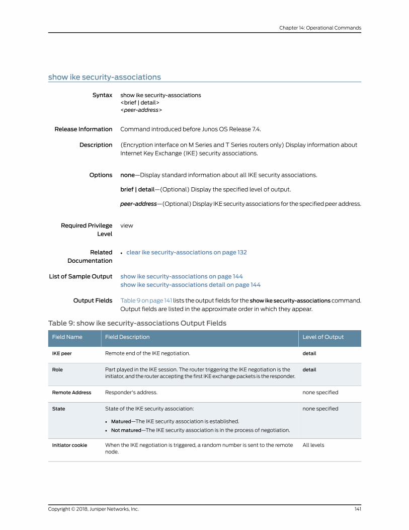
show ike security-associations
Syntax show ike security-associations<brief | detail><peer-address>
Release Information Command introduced before Junos OS Release 7.4.
Description (Encryption interface on M Series and T Series routers only) Display information about
Internet Key Exchange (IKE) security associations.
Options none—Display standard information about all IKE security associations.
brief | detail—(Optional) Display the specified level of output.
peer-address—(Optional)Display IKEsecurity associations for the specifiedpeeraddress.
Required PrivilegeLevel
view
RelatedDocumentation
clear ike security-associations on page 132•
List of Sample Output show ike security-associations on page 144show ike security-associations detail on page 144
Output Fields Table9onpage 141 lists theoutput fields for the show ikesecurity-associations command.
Output fields are listed in the approximate order in which they appear.
Table 9: show ike security-associations Output Fields
Level of OutputField DescriptionField Name
detailRemote end of the IKE negotiation.IKE peer
detailPart played in the IKE session. The router triggering the IKE negotiation is theinitiator, and the router accepting the first IKEexchangepackets is the responder.
Role
none specifiedResponder's address.Remote Address
none specifiedState of the IKE security association:
• Matured—The IKE security association is established.
• Notmatured—The IKE security association is in the process of negotiation.
State
All levelsWhen the IKE negotiation is triggered, a random number is sent to the remotenode.
Initiator cookie
141Copyright © 2018, Juniper Networks, Inc.
Chapter 14: Operational Commands
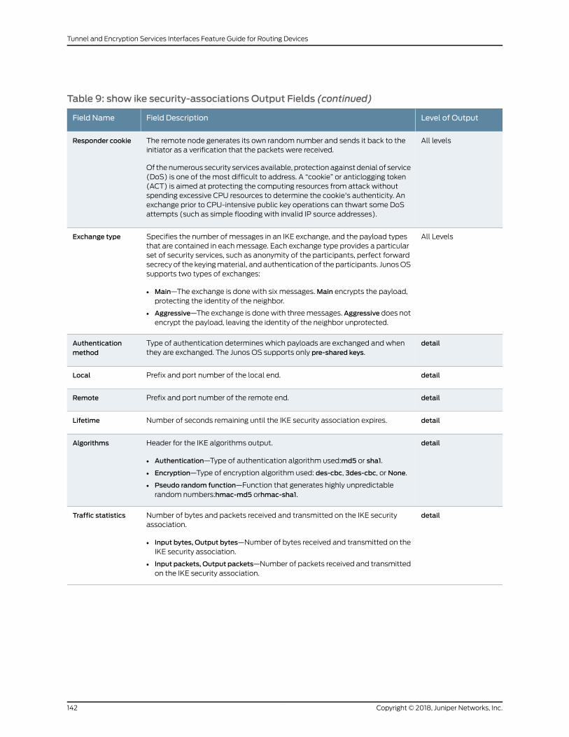
Table 9: show ike security-associations Output Fields (continued)
Level of OutputField DescriptionField Name
All levelsThe remote node generates its own random number and sends it back to theinitiator as a verification that the packets were received.
Of the numerous security services available, protection against denial of service(DoS) is one of the most difficult to address. A “cookie” or anticlogging token(ACT) is aimed at protecting the computing resources from attack withoutspending excessive CPU resources to determine the cookie's authenticity. Anexchange prior to CPU-intensive public key operations can thwart some DoSattempts (such as simple flooding with invalid IP source addresses).
Responder cookie
All LevelsSpecifies the number of messages in an IKE exchange, and the payload typesthat are contained in eachmessage. Each exchange type provides a particularset of security services, such as anonymity of the participants, perfect forwardsecrecy of the keyingmaterial, and authentication of the participants. JunosOSsupports two types of exchanges:
• Main—The exchange is done with six messages.Main encrypts the payload,protecting the identity of the neighbor.
• Aggressive—The exchange is donewith threemessages. Aggressive does notencrypt the payload, leaving the identity of the neighbor unprotected.
Exchange type
detailType of authentication determines which payloads are exchanged and whenthey are exchanged. The Junos OS supports only pre-shared keys.
Authenticationmethod
detailPrefix and port number of the local end.Local
detailPrefix and port number of the remote end.Remote
detailNumber of seconds remaining until the IKE security association expires.Lifetime
detailHeader for the IKE algorithms output.
• Authentication—Type of authentication algorithm used:md5 or sha1.
• Encryption—Type of encryption algorithm used: des-cbc, 3des-cbc, or None.
• Pseudo random function—Function that generates highly unpredictablerandom numbers:hmac-md5 orhmac-sha1.
Algorithms
detailNumber of bytes and packets received and transmitted on the IKE securityassociation.
• Input bytes, Output bytes—Number of bytes received and transmitted on theIKE security association.
• Input packets, Output packets—Number of packets received and transmittedon the IKE security association.
Traffic statistics
Copyright © 2018, Juniper Networks, Inc.142
Tunnel and Encryption Services Interfaces Feature Guide for Routing Devices
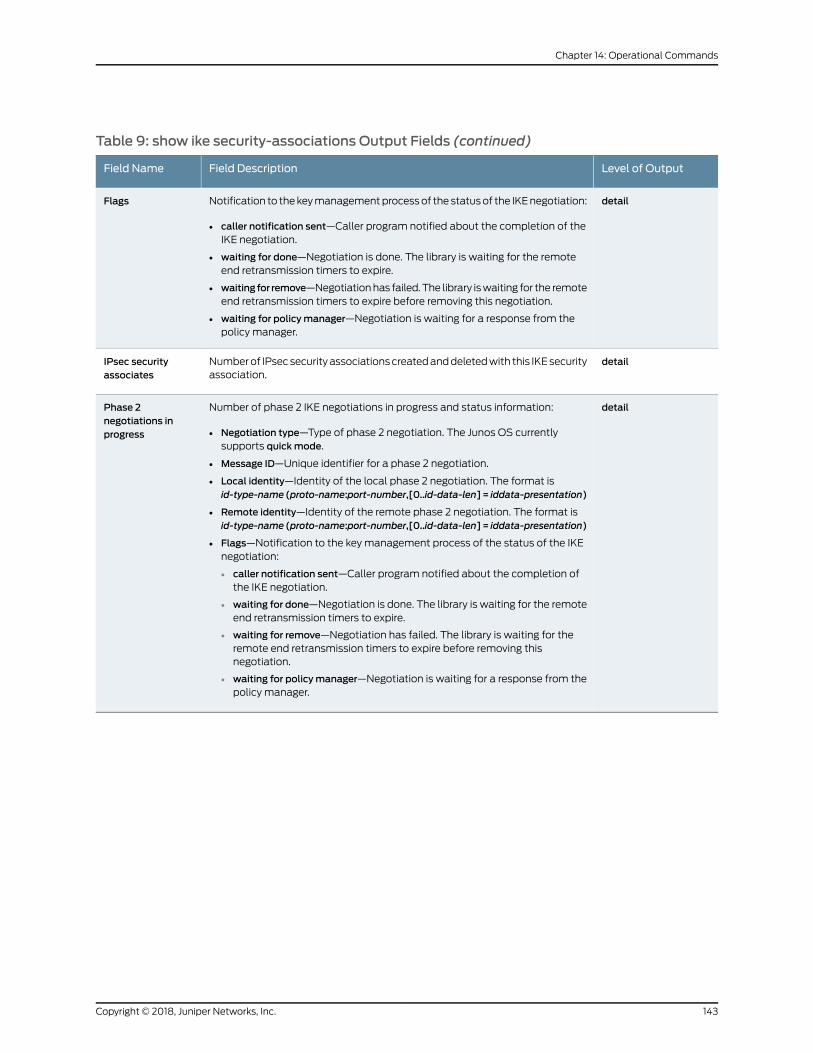
Table 9: show ike security-associations Output Fields (continued)
Level of OutputField DescriptionField Name
detailNotification to thekeymanagementprocessof the statusof the IKEnegotiation:
• caller notification sent—Caller program notified about the completion of theIKE negotiation.
• waiting for done—Negotiation is done. The library is waiting for the remoteend retransmission timers to expire.
• waiting for remove—Negotiationhas failed.The library iswaiting for the remoteend retransmission timers to expire before removing this negotiation.
• waiting for policymanager—Negotiation is waiting for a response from thepolicy manager.
Flags
detailNumberof IPsecsecurityassociationscreatedanddeletedwith this IKEsecurityassociation.
IPsec securityassociates
detailNumber of phase 2 IKE negotiations in progress and status information:
• Negotiation type—Type of phase 2 negotiation. The Junos OS currentlysupports quickmode.
• Message ID—Unique identifier for a phase 2 negotiation.
• Local identity—Identity of the local phase 2 negotiation. The format isid-type-name (proto-name:port-number,[0..id-data-len]= iddata-presentation)
• Remote identity—Identity of the remote phase 2 negotiation. The format isid-type-name (proto-name:port-number,[0..id-data-len]= iddata-presentation)
• Flags—Notification to the key management process of the status of the IKEnegotiation:
• caller notification sent—Caller program notified about the completion ofthe IKE negotiation.
• waiting for done—Negotiation is done. The library is waiting for the remoteend retransmission timers to expire.
• waiting for remove—Negotiation has failed. The library is waiting for theremote end retransmission timers to expire before removing thisnegotiation.
• waiting for policymanager—Negotiation is waiting for a response from thepolicy manager.
Phase 2negotiations inprogress
143Copyright © 2018, Juniper Networks, Inc.
Chapter 14: Operational Commands
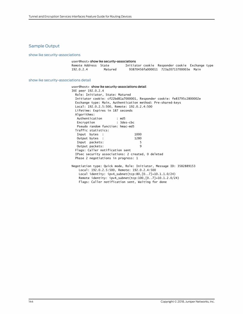
Sample Output
show ike security-associations
user@host> show ike security-associationsRemote Address State Initiator cookie Responder cookie Exchange type192.0.2.4 Matured 93870456fa000011 723a20713700003e Main
show ike security-associations detail
user@host> show ike security-associations detailIKE peer 192.0.2.4 Role: Initiator, State: Matured Initiator cookie: cf22bd81a7000001, Responder cookie: fe83795c2800002e Exchange type: Main, Authentication method: Pre-shared-keys Local: 192.0.2.5:500, Remote: 192.0.2.4:500 Lifetime: Expires in 187 seconds Algorithms: Authentication : md5 Encryption : 3des-cbc Pseudo random function: hmac-md5 Traffic statistics: Input bytes : 1000 Output bytes : 1280 Input packets: 5 Output packets: 9 Flags: Caller notification sent IPsec security associations: 2 created, 0 deleted Phase 2 negotiations in progress: 1
Negotiation type: Quick mode, Role: Initiator, Message ID: 3582889153 Local: 192.0.2.5:500, Remote: 192.0.2.4:500 Local identity: ipv4_subnet(tcp:80,[0..7]=10.1.1.0/24) Remote identity: ipv4_subnet(tcp:100,[0..7]=10.1.2.0/24) Flags: Caller notification sent, Waiting for done
Copyright © 2018, Juniper Networks, Inc.144
Tunnel and Encryption Services Interfaces Feature Guide for Routing Devices
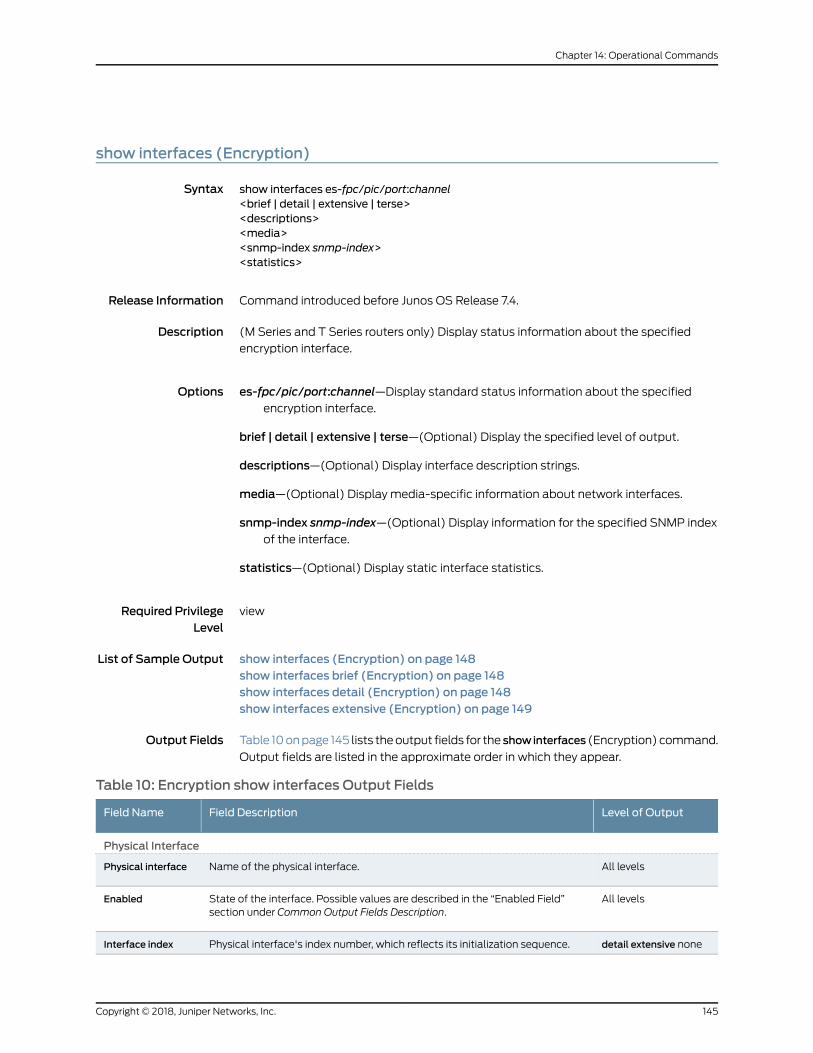
show interfaces (Encryption)
Syntax show interfaces es-fpc/pic/port:channel<brief | detail | extensive | terse><descriptions><media><snmp-index snmp-index><statistics>
Release Information Command introduced before Junos OS Release 7.4.
Description (M Series and T Series routers only) Display status information about the specified
encryption interface.
Options es-fpc/pic/port:channel—Display standard status information about the specifiedencryption interface.
brief | detail | extensive | terse—(Optional) Display the specified level of output.
descriptions—(Optional) Display interface description strings.
media—(Optional) Display media-specific information about network interfaces.
snmp-index snmp-index—(Optional) Display information for the specified SNMP indexof the interface.
statistics—(Optional) Display static interface statistics.
Required PrivilegeLevel
view
List of Sample Output show interfaces (Encryption) on page 148show interfaces brief (Encryption) on page 148show interfaces detail (Encryption) on page 148show interfaces extensive (Encryption) on page 149
Output Fields Table 10onpage 145 lists theoutput fields for the showinterfaces (Encryption) command.
Output fields are listed in the approximate order in which they appear.
Table 10: Encryption show interfaces Output Fields
Level of OutputField DescriptionField Name
Physical Interface
All levelsName of the physical interface.Physical interface
All levelsState of the interface. Possible values are described in the “Enabled Field”section under Common Output Fields Description.
Enabled
detail extensive nonePhysical interface's index number, which reflects its initialization sequence.Interface index
145Copyright © 2018, Juniper Networks, Inc.
Chapter 14: Operational Commands
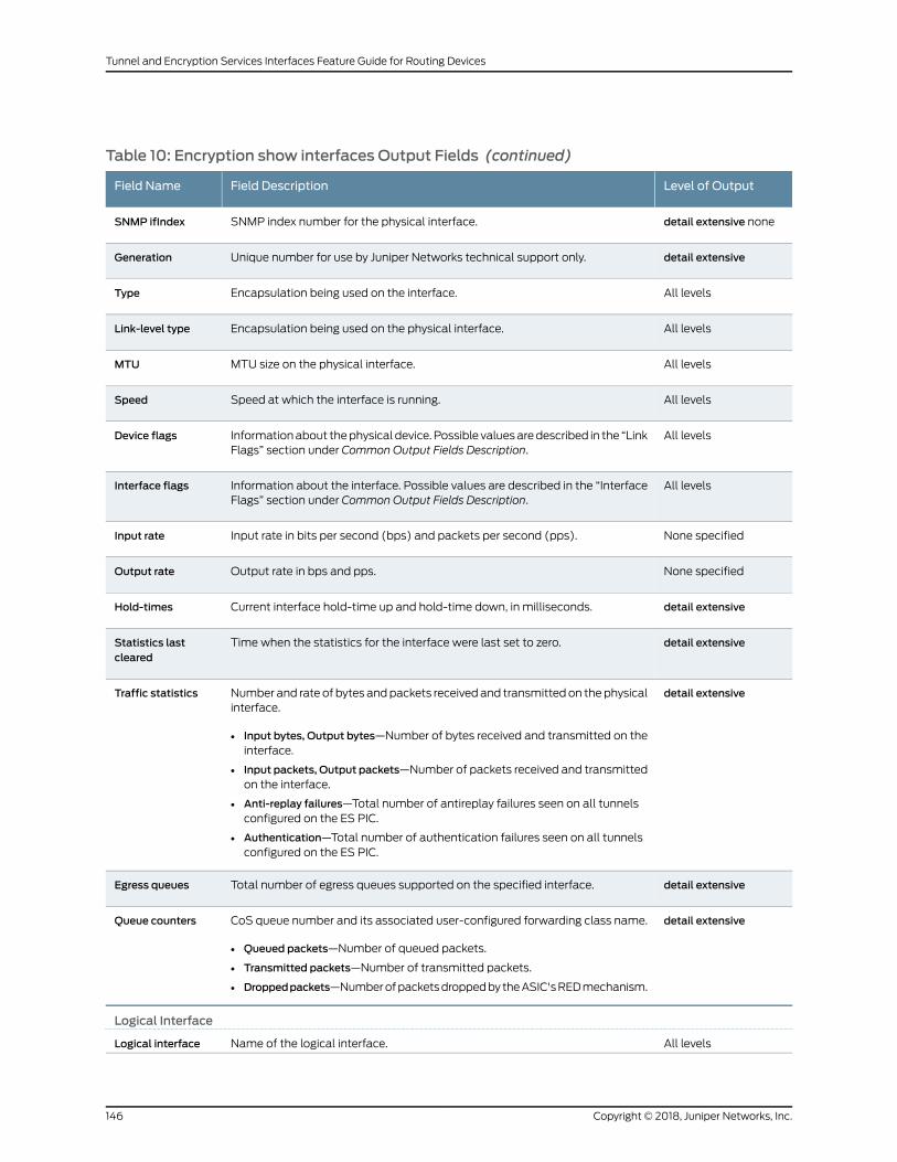
Table 10: Encryption show interfaces Output Fields (continued)
Level of OutputField DescriptionField Name
detail extensive noneSNMP index number for the physical interface.SNMP ifIndex
detail extensiveUnique number for use by Juniper Networks technical support only.Generation
All levelsEncapsulation being used on the interface.Type
All levelsEncapsulation being used on the physical interface.Link-level type
All levelsMTU size on the physical interface.MTU
All levelsSpeed at which the interface is running.Speed
All levelsInformationabout thephysical device. Possible valuesaredescribed in the “LinkFlags” section under Common Output Fields Description.
Device flags
All levelsInformation about the interface. Possible values are described in the “InterfaceFlags” section under Common Output Fields Description.
Interface flags
None specifiedInput rate in bits per second (bps) and packets per second (pps).Input rate
None specifiedOutput rate in bps and pps.Output rate
detail extensiveCurrent interface hold-time up and hold-time down, in milliseconds.Hold-times
detail extensiveTime when the statistics for the interface were last set to zero.Statistics lastcleared
detail extensiveNumber and rate of bytes andpackets receivedand transmittedon thephysicalinterface.
• Input bytes, Output bytes—Number of bytes received and transmitted on theinterface.
• Input packets, Output packets—Number of packets received and transmittedon the interface.
• Anti-replay failures—Total number of antireplay failures seen on all tunnelsconfigured on the ES PIC.
• Authentication—Total number of authentication failures seen on all tunnelsconfigured on the ES PIC.
Traffic statistics
detail extensiveTotal number of egress queues supported on the specified interface.Egress queues
detail extensiveCoS queue number and its associated user-configured forwarding class name.
• Queued packets—Number of queued packets.
• Transmitted packets—Number of transmitted packets.
• Droppedpackets—Numberofpacketsdroppedby theASIC'sREDmechanism.
Queue counters
Logical Interface
All levelsName of the logical interface.Logical interface
Copyright © 2018, Juniper Networks, Inc.146
Tunnel and Encryption Services Interfaces Feature Guide for Routing Devices
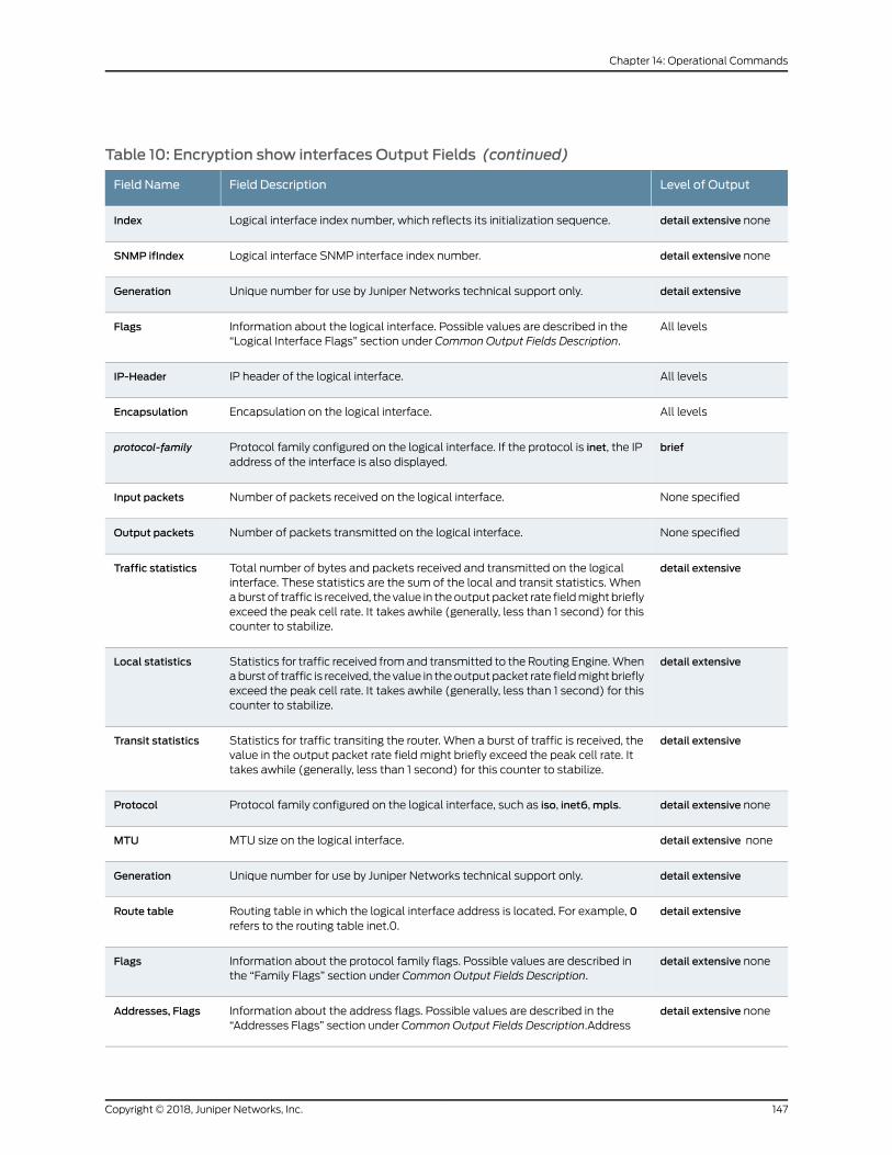
Table 10: Encryption show interfaces Output Fields (continued)
Level of OutputField DescriptionField Name
detail extensive noneLogical interface index number, which reflects its initialization sequence.Index
detail extensive noneLogical interface SNMP interface index number.SNMP ifIndex
detail extensiveUnique number for use by Juniper Networks technical support only.Generation
All levelsInformation about the logical interface. Possible values are described in the“Logical Interface Flags” section under Common Output Fields Description.
Flags
All levelsIP header of the logical interface.IP-Header
All levelsEncapsulation on the logical interface.Encapsulation
briefProtocol family configured on the logical interface. If the protocol is inet, the IPaddress of the interface is also displayed.
protocol-family
None specifiedNumber of packets received on the logical interface.Input packets
None specifiedNumber of packets transmitted on the logical interface.Output packets
detail extensiveTotal number of bytes and packets received and transmitted on the logicalinterface. These statistics are the sum of the local and transit statistics. Whenaburst of traffic is received, the value in theoutputpacket rate fieldmightbrieflyexceed the peak cell rate. It takes awhile (generally, less than 1 second) for thiscounter to stabilize.
Traffic statistics
detail extensiveStatistics for traffic received fromand transmitted to the Routing Engine.Whenaburst of traffic is received, the value in theoutputpacket rate fieldmightbrieflyexceed the peak cell rate. It takes awhile (generally, less than 1 second) for thiscounter to stabilize.
Local statistics
detail extensiveStatistics for traffic transiting the router. When a burst of traffic is received, thevalue in the output packet rate field might briefly exceed the peak cell rate. Ittakes awhile (generally, less than 1 second) for this counter to stabilize.
Transit statistics
detail extensive noneProtocol family configured on the logical interface, such as iso, inet6,mpls.Protocol
detail extensive noneMTU size on the logical interface.MTU
detail extensiveUnique number for use by Juniper Networks technical support only.Generation
detail extensiveRouting table in which the logical interface address is located. For example, 0refers to the routing table inet.0.
Route table
detail extensive noneInformation about the protocol family flags. Possible values are described inthe “Family Flags” section under Common Output Fields Description.
Flags
detail extensive noneInformation about the address flags. Possible values are described in the“Addresses Flags” section under Common Output Fields Description.Address
Addresses, Flags
147Copyright © 2018, Juniper Networks, Inc.
Chapter 14: Operational Commands
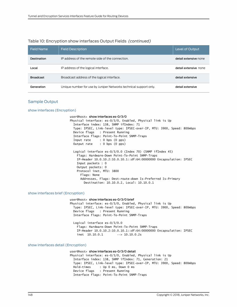
Table 10: Encryption show interfaces Output Fields (continued)
Level of OutputField DescriptionField Name
detail extensive noneIP address of the remote side of the connection.Destination
detail extensive noneIP address of the logical interface.Local
detail extensiveBroadcast address of the logical interface.Broadcast
detail extensiveUnique number for use by Juniper Networks technical support only.Generation
Sample Output
show interfaces (Encryption)
user@host> show interfaces es-0/3/0Physical interface: es-0/3/0, Enabled, Physical link is Up Interface index: 138, SNMP ifIndex: 71 Type: IPSEC, Link-level type: IPSEC-over-IP, MTU: 3900, Speed: 800mbps Device flags : Present Running Interface flags: Point-To-Point SNMP-Traps Input rate : 0 bps (0 pps) Output rate : 0 bps (0 pps)
Logical interface es-0/3/0.0 (Index 70) (SNMP ifIndex 45) Flags: Hardware-Down Point-To-Point SNMP-Traps IP-Header 10.0.10.2:10.0.10.1::df:64:00000000 Encapsulation: IPSEC Input packets : 0 Output packets: 0 Protocol inet, MTU: 3800 Flags: None Addresses, Flags: Dest-route-down Is-Preferred Is-Primary Destination: 10.10.0.2, Local: 10.10.0.1
show interfaces brief (Encryption)
user@host> show interfaces es-0/3/0 briefPhysical interface: es-0/3/0, Enabled, Physical link is Up Type: IPSEC, Link-level type: IPSEC-over-IP, MTU: 3900, Speed: 800mbps Device flags : Present Running Interface flags: Point-To-Point SNMP-Traps
Logical interface es-0/3/0.0 Flags: Hardware-Down Point-To-Point SNMP-Traps IP-Header 10.0.10.2:10.0.10.1::df:64:00000000 Encapsulation: IPSEC inet 10.10.0.1 --> 10.10.0.2s
show interfaces detail (Encryption)
user@host> show interfaces es-0/3/0 detailPhysical interface: es-0/3/0, Enabled, Physical link is Up Interface index: 138, SNMP ifIndex: 71, Generation: 21 Type: IPSEC, Link-level type: IPSEC-over-IP, MTU: 3900, Speed: 800mbps Hold-times : Up 0 ms, Down 0 ms Device flags : Present Running Interface flags: Point-To-Point SNMP-Traps
Copyright © 2018, Juniper Networks, Inc.148
Tunnel and Encryption Services Interfaces Feature Guide for Routing Devices
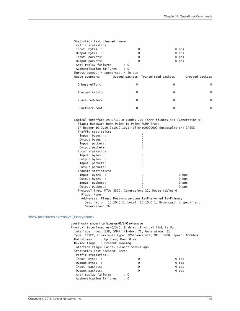
Statistics last cleared: Never Traffic statistics: Input bytes : 0 0 bps Output bytes : 0 0 bps Input packets: 0 0 pps Output packets: 0 0 pps Anti-replay failures : 0 Authentication failures : 0 Egress queues: 4 supported, 4 in use Queue counters: Queued packets Transmitted packets Dropped packets
0 best-effort 0 0 0
1 expedited-fo 0 0 0
2 assured-forw 0 0 0
3 network-cont 0 0 0
Logical interface es-0/3/0.0 (Index 70) (SNMP ifIndex 45) (Generation 9) Flags: Hardware-Down Point-To-Point SNMP-Traps IP-Header 10.0.10.2:10.0.10.1::df:64:00000000 Encapsulation: IPSEC Traffic statistics: Input bytes : 0 Output bytes : 0 Input packets: 0 Output packets: 0 Local statistics: Input bytes : 0 Output bytes : 0 Input packets: 0 Output packets: 0 Transit statistics: Input bytes : 0 0 bps Output bytes : 0 0 bps Input packets: 0 0 pps Output packets: 0 0 pps Protocol inet, MTU: 3800, Generation: 22, Route table: 0 Flags: None Addresses, Flags: Dest-route-down Is-Preferred Is-Primary Destination: 10.10.0.2, Local: 10.10.0.1, Broadcast: Unspecified, Generation: 26
show interfaces extensive (Encryption)
user@host> show interfaces es-0/3/0 extensivePhysical interface: es-0/3/0, Enabled, Physical link is Up Interface index: 138, SNMP ifIndex: 71, Generation: 21 Type: IPSEC, Link-level type: IPSEC-over-IP, MTU: 3900, Speed: 800mbps Hold-times : Up 0 ms, Down 0 ms Device flags : Present Running Interface flags: Point-To-Point SNMP-Traps Statistics last cleared: Never Traffic statistics: Input bytes : 0 0 bps Output bytes : 0 0 bps Input packets: 0 0 pps Output packets: 0 0 pps Anti-replay failures : 0 Authentication failures : 0
149Copyright © 2018, Juniper Networks, Inc.
Chapter 14: Operational Commands
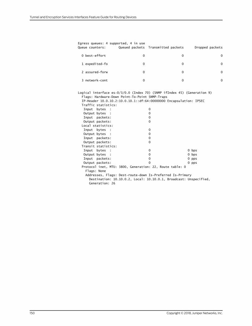
Egress queues: 4 supported, 4 in use Queue counters: Queued packets Transmitted packets Dropped packets
0 best-effort 0 0 0
1 expedited-fo 0 0 0
2 assured-forw 0 0 0
3 network-cont 0 0 0
Logical interface es-0/3/0.0 (Index 70) (SNMP ifIndex 45) (Generation 9) Flags: Hardware-Down Point-To-Point SNMP-Traps IP-Header 10.0.10.2:10.0.10.1::df:64:00000000 Encapsulation: IPSEC Traffic statistics: Input bytes : 0 Output bytes : 0 Input packets: 0 Output packets: 0 Local statistics: Input bytes : 0 Output bytes : 0 Input packets: 0 Output packets: 0 Transit statistics: Input bytes : 0 0 bps Output bytes : 0 0 bps Input packets: 0 0 pps Output packets: 0 0 pps Protocol inet, MTU: 3800, Generation: 22, Route table: 0 Flags: None Addresses, Flags: Dest-route-down Is-Preferred Is-Primary Destination: 10.10.0.2, Local: 10.10.0.1, Broadcast: Unspecified, Generation: 26
Copyright © 2018, Juniper Networks, Inc.150
Tunnel and Encryption Services Interfaces Feature Guide for Routing Devices
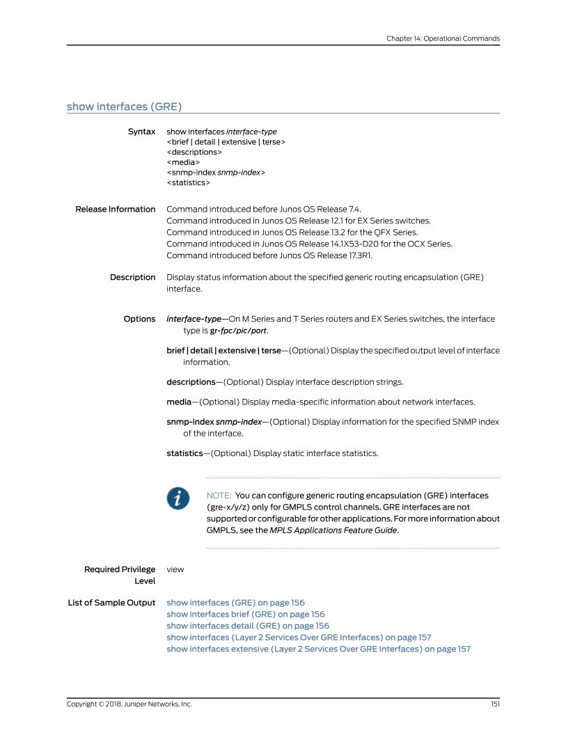
show interfaces (GRE)
Syntax show interfaces interface-type<brief | detail | extensive | terse><descriptions><media><snmp-index snmp-index><statistics>
Release Information Command introduced before Junos OS Release 7.4.
Command introduced in Junos OS Release 12.1 for EX Series switches.
Command introduced in Junos OS Release 13.2 for the QFX Series.
Command introduced in Junos OS Release 14.1X53-D20 for the OCX Series.
Command introduced before Junos OS Release 17.3R1.
Description Display status information about the specified generic routing encapsulation (GRE)
interface.
Options interface-type—OnM Series and T Series routers and EX Series switches, the interface
type is gr-fpc/pic/port.
brief |detail | extensive | terse—(Optional)Display the specifiedoutput level of interfaceinformation.
descriptions—(Optional) Display interface description strings.
media—(Optional) Display media-specific information about network interfaces.
snmp-index snmp-index—(Optional) Display information for the specified SNMP indexof the interface.
statistics—(Optional) Display static interface statistics.
NOTE: You can configure generic routing encapsulation (GRE) interfaces(gre-x/y/z) only for GMPLS control channels. GRE interfaces are notsupportedor configurable forotherapplications. Formore informationaboutGMPLS, see theMPLS Applications Feature Guide.
Required PrivilegeLevel
view
List of Sample Output show interfaces (GRE) on page 156show interfaces brief (GRE) on page 156show interfaces detail (GRE) on page 156show interfaces (Layer 2 Services Over GRE Interfaces) on page 157show interfaces extensive (Layer 2 Services Over GRE Interfaces) on page 157
151Copyright © 2018, Juniper Networks, Inc.
Chapter 14: Operational Commands
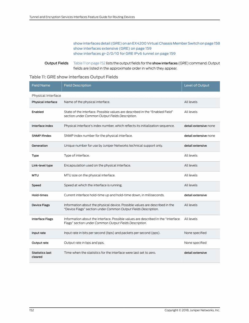
showinterfacesdetail (GRE)onanEX4200VirtualChassisMemberSwitchonpage158show interfaces extensive (GRE) on page 159show interfaces gr-2/0/10 for GRE IPv6 tunnel on page 159
Output Fields Table 11 onpage 152 lists theoutput fields for the showinterfaces (GRE)command.Output
fields are listed in the approximate order in which they appear.
Table 11: GRE show interfaces Output Fields
Level of OutputField DescriptionField Name
Physical Interface
All levelsName of the physical interface.Physical interface
All levelsState of the interface. Possible values are described in the “Enabled Field”section under Common Output Fields Description.
Enabled
detail extensive nonePhysical interface's index number, which reflects its initialization sequence.Interface index
detail extensive noneSNMP index number for the physical interface.SNMP ifIndex
detail extensiveUnique number for use by Juniper Networks technical support only.Generation
All levelsType of interface.Type
All levelsEncapsulation used on the physical interface.Link-level type
All levelsMTU size on the physical interface.MTU
All levelsSpeed at which the interface is running.Speed
detail extensiveCurrent interface hold-time up and hold-time down, in milliseconds.Hold-times
All levelsInformation about the physical device. Possible values are described in the“Device Flags” section under Common Output Fields Description.
Device Flags
All levelsInformation about the interface. Possible values are described in the “InterfaceFlags” section under Common Output Fields Description.
Interface Flags
None specifiedInput rate in bits per second (bps) and packets per second (pps).Input rate
None specifiedOutput rate in bps and pps.Output rate
detail extensiveTime when the statistics for the interface were last set to zero.Statistics lastcleared
Copyright © 2018, Juniper Networks, Inc.152
Tunnel and Encryption Services Interfaces Feature Guide for Routing Devices

Table 11: GRE show interfaces Output Fields (continued)
Level of OutputField DescriptionField Name
detail extensiveThe number of and the rate at which input and output bytes and packets arereceived and transmitted on the physical interface.
• Input bytes—Number of bytes received on the interface.
• Output bytes—Number of bytes transmitted on the interface.
• Input packets—Number of packets received on the interface.
• Output packets—Number of packets transmitted on the interface.
Traffic statistics
Logical Interface
All levelsName of the logical interface.Logical interface
detail extensive noneLogical interface index number, which reflects its initialization sequence.Index
detail extensive noneLogical interface SNMP interface index number.SNMP ifIndex
detail extensiveUnique number for use by Juniper Networks technical support.Generation
All levelsInformation about the logical interface. Possible values listed in the “LogicalInterface Flags” section under Common Output Fields Description. describegeneral information about the logical interface.
GRE-specific informationabout the logical interface is indicatedby thepresenceor absence of the following value in this field:
• Reassemble-Pkts—If the Flags field includes this string, the GRE tunnel isconfigured to reassemble tunnel packets that were fragmented after tunnelencapsulation.
Flags
All levelsIP header of the logical interface. If the tunnel key statement is configured, thisinformation is included in the IP Header entry.
GRE-specific informationabout the logical interface is indicatedby thepresenceor absence of the following value in this field:
• df—If the IP-Header field includes this string immediately following the 16bitsof identification information (that is, if :df: displays after the twelfth byte),the GRE tunnel is configured to allow fragmentation of GRE packets afterencapsulation.
IP-Header
All levelsEncapsulation on the logical interface.Encapsulation
All levelsName of the Layer 2 routing instance associated with the GRE interface.L2Routing Instance
All levelsName of the Layer 3 routing instance associated with the GRE interface.L3Routing Instance
153Copyright © 2018, Juniper Networks, Inc.
Chapter 14: Operational Commands
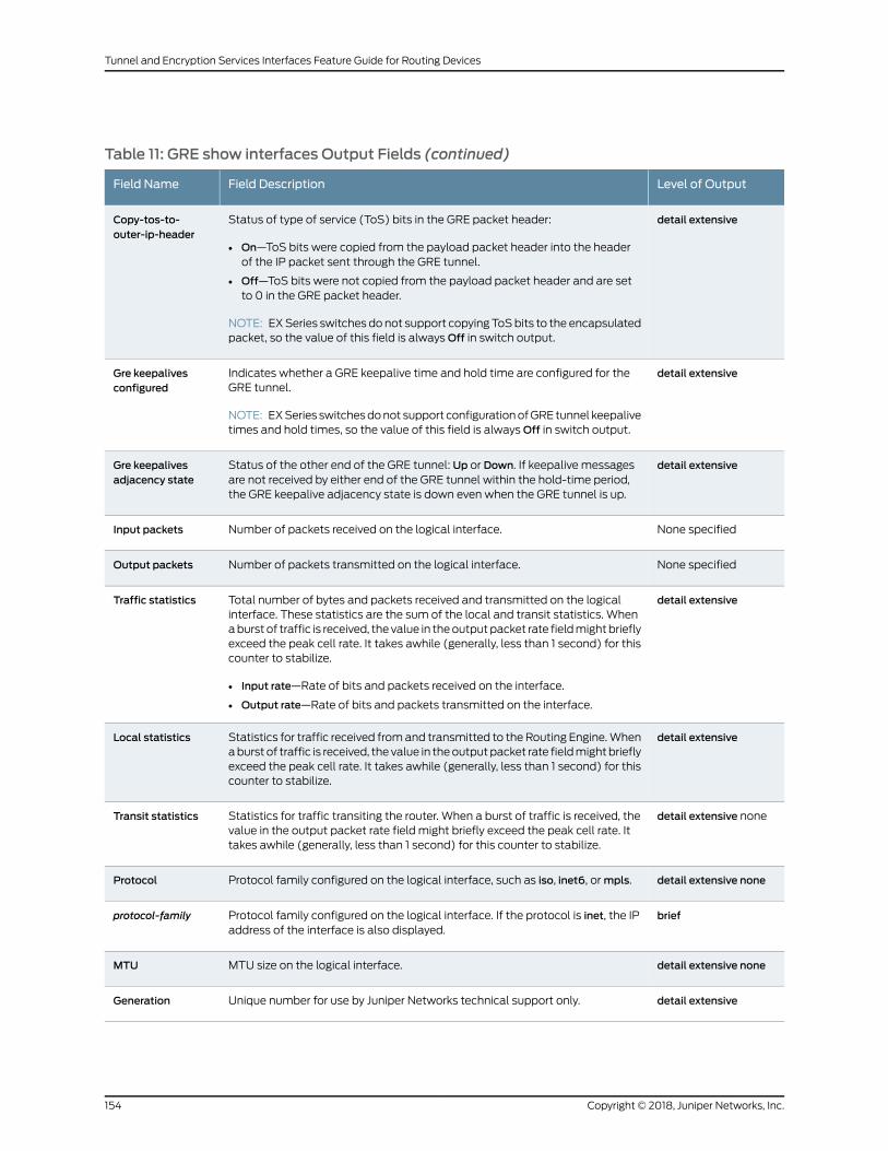
Table 11: GRE show interfaces Output Fields (continued)
Level of OutputField DescriptionField Name
detail extensiveStatus of type of service (ToS) bits in the GRE packet header:
• On—ToS bits were copied from the payload packet header into the headerof the IP packet sent through the GRE tunnel.
• Off—ToS bits were not copied from the payload packet header and are setto 0 in the GRE packet header.
NOTE: EXSeries switches do not support copying ToSbits to the encapsulatedpacket, so the value of this field is alwaysOff in switch output.
Copy-tos-to-outer-ip-header
detail extensiveIndicates whether a GRE keepalive time and hold time are configured for theGRE tunnel.
NOTE: EXSeries switchesdonot support configurationofGRE tunnel keepalivetimes and hold times, so the value of this field is alwaysOff in switch output.
Gre keepalivesconfigured
detail extensiveStatus of the other end of the GRE tunnel: Up or Down. If keepalive messagesare not received by either end of the GRE tunnel within the hold-time period,the GRE keepalive adjacency state is down even when the GRE tunnel is up.
Gre keepalivesadjacency state
None specifiedNumber of packets received on the logical interface.Input packets
None specifiedNumber of packets transmitted on the logical interface.Output packets
detail extensiveTotal number of bytes and packets received and transmitted on the logicalinterface. These statistics are the sum of the local and transit statistics. Whenaburst of traffic is received, the value in theoutputpacket rate fieldmightbrieflyexceed the peak cell rate. It takes awhile (generally, less than 1 second) for thiscounter to stabilize.
• Input rate—Rate of bits and packets received on the interface.
• Output rate—Rate of bits and packets transmitted on the interface.
Traffic statistics
detail extensiveStatistics for traffic received fromand transmitted to the Routing Engine.Whenaburst of traffic is received, the value in theoutputpacket rate fieldmightbrieflyexceed the peak cell rate. It takes awhile (generally, less than 1 second) for thiscounter to stabilize.
Local statistics
detail extensive noneStatistics for traffic transiting the router. When a burst of traffic is received, thevalue in the output packet rate field might briefly exceed the peak cell rate. Ittakes awhile (generally, less than 1 second) for this counter to stabilize.
Transit statistics
detail extensive noneProtocol family configured on the logical interface, such as iso, inet6, ormpls.Protocol
briefProtocol family configured on the logical interface. If the protocol is inet, the IPaddress of the interface is also displayed.
protocol-family
detail extensive noneMTU size on the logical interface.MTU
detail extensiveUnique number for use by Juniper Networks technical support only.Generation
Copyright © 2018, Juniper Networks, Inc.154
Tunnel and Encryption Services Interfaces Feature Guide for Routing Devices
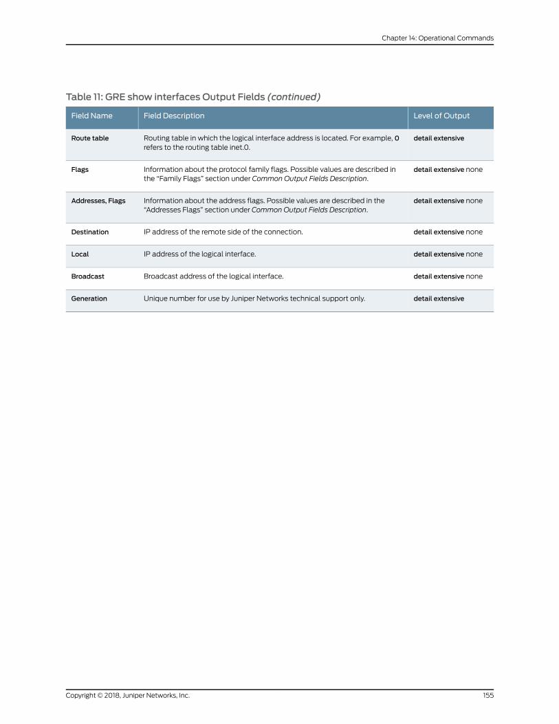
Table 11: GRE show interfaces Output Fields (continued)
Level of OutputField DescriptionField Name
detail extensiveRouting table in which the logical interface address is located. For example, 0refers to the routing table inet.0.
Route table
detail extensive noneInformation about the protocol family flags. Possible values are described inthe “Family Flags” section under Common Output Fields Description.
Flags
detail extensive noneInformation about the address flags. Possible values are described in the“Addresses Flags” section under Common Output Fields Description.
Addresses, Flags
detail extensive noneIP address of the remote side of the connection.Destination
detail extensive noneIP address of the logical interface.Local
detail extensive noneBroadcast address of the logical interface.Broadcast
detail extensiveUnique number for use by Juniper Networks technical support only.Generation
155Copyright © 2018, Juniper Networks, Inc.
Chapter 14: Operational Commands
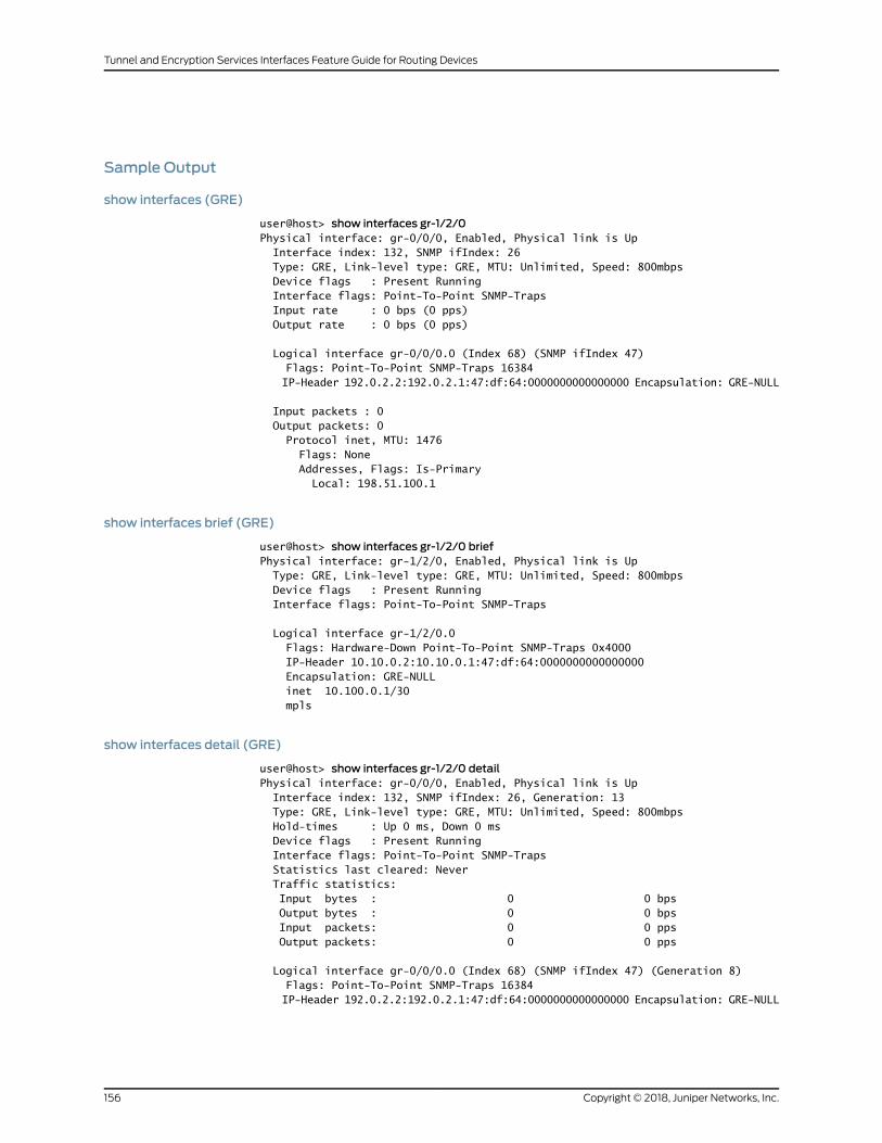
Sample Output
show interfaces (GRE)
user@host> show interfaces gr-1/2/0Physical interface: gr-0/0/0, Enabled, Physical link is Up Interface index: 132, SNMP ifIndex: 26 Type: GRE, Link-level type: GRE, MTU: Unlimited, Speed: 800mbps Device flags : Present Running Interface flags: Point-To-Point SNMP-Traps Input rate : 0 bps (0 pps) Output rate : 0 bps (0 pps)
Logical interface gr-0/0/0.0 (Index 68) (SNMP ifIndex 47) Flags: Point-To-Point SNMP-Traps 16384 IP-Header 192.0.2.2:192.0.2.1:47:df:64:0000000000000000 Encapsulation: GRE-NULL
Input packets : 0 Output packets: 0 Protocol inet, MTU: 1476 Flags: None Addresses, Flags: Is-Primary Local: 198.51.100.1
show interfaces brief (GRE)
user@host> show interfaces gr-1/2/0 briefPhysical interface: gr-1/2/0, Enabled, Physical link is Up Type: GRE, Link-level type: GRE, MTU: Unlimited, Speed: 800mbps Device flags : Present Running Interface flags: Point-To-Point SNMP-Traps
Logical interface gr-1/2/0.0 Flags: Hardware-Down Point-To-Point SNMP-Traps 0x4000 IP-Header 10.10.0.2:10.10.0.1:47:df:64:0000000000000000 Encapsulation: GRE-NULL inet 10.100.0.1/30 mpls
show interfaces detail (GRE)
user@host> show interfaces gr-1/2/0 detailPhysical interface: gr-0/0/0, Enabled, Physical link is Up Interface index: 132, SNMP ifIndex: 26, Generation: 13 Type: GRE, Link-level type: GRE, MTU: Unlimited, Speed: 800mbps Hold-times : Up 0 ms, Down 0 ms Device flags : Present Running Interface flags: Point-To-Point SNMP-Traps Statistics last cleared: Never Traffic statistics: Input bytes : 0 0 bps Output bytes : 0 0 bps Input packets: 0 0 pps Output packets: 0 0 pps
Logical interface gr-0/0/0.0 (Index 68) (SNMP ifIndex 47) (Generation 8) Flags: Point-To-Point SNMP-Traps 16384 IP-Header 192.0.2.2:192.0.2.1:47:df:64:0000000000000000 Encapsulation: GRE-NULL
Copyright © 2018, Juniper Networks, Inc.156
Tunnel and Encryption Services Interfaces Feature Guide for Routing Devices
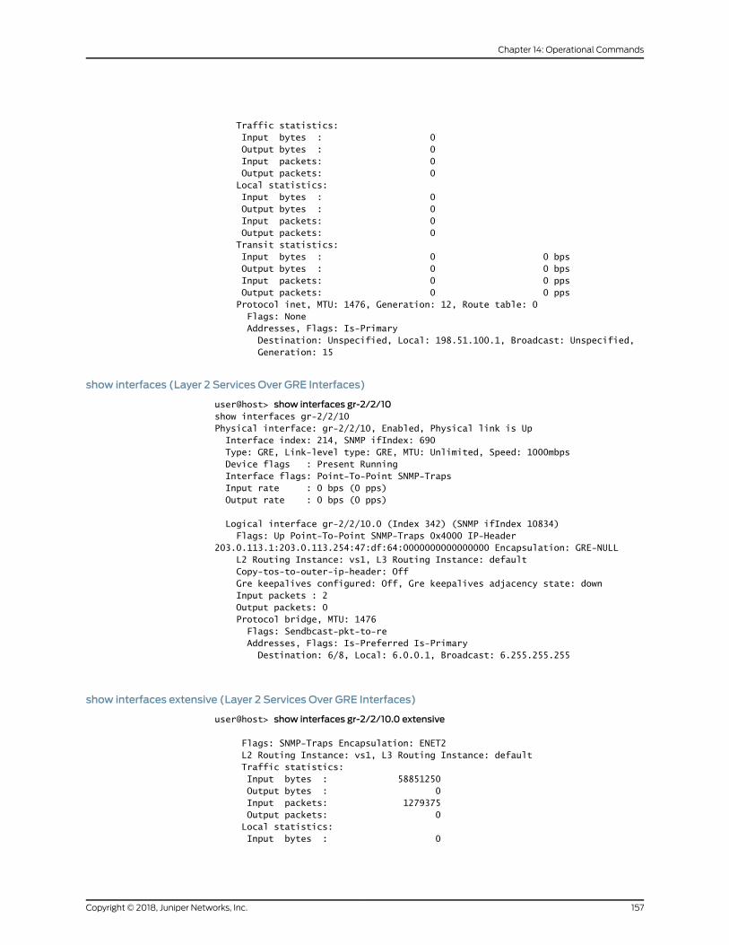
Traffic statistics: Input bytes : 0 Output bytes : 0 Input packets: 0 Output packets: 0 Local statistics: Input bytes : 0 Output bytes : 0 Input packets: 0 Output packets: 0 Transit statistics: Input bytes : 0 0 bps Output bytes : 0 0 bps Input packets: 0 0 pps Output packets: 0 0 pps Protocol inet, MTU: 1476, Generation: 12, Route table: 0 Flags: None Addresses, Flags: Is-Primary Destination: Unspecified, Local: 198.51.100.1, Broadcast: Unspecified, Generation: 15
show interfaces (Layer 2 Services Over GRE Interfaces)
user@host> show interfaces gr-2/2/10show interfaces gr-2/2/10 Physical interface: gr-2/2/10, Enabled, Physical link is Up Interface index: 214, SNMP ifIndex: 690 Type: GRE, Link-level type: GRE, MTU: Unlimited, Speed: 1000mbps Device flags : Present Running Interface flags: Point-To-Point SNMP-Traps Input rate : 0 bps (0 pps) Output rate : 0 bps (0 pps)
Logical interface gr-2/2/10.0 (Index 342) (SNMP ifIndex 10834) Flags: Up Point-To-Point SNMP-Traps 0x4000 IP-Header 203.0.113.1:203.0.113.254:47:df:64:0000000000000000 Encapsulation: GRE-NULL L2 Routing Instance: vs1, L3 Routing Instance: default Copy-tos-to-outer-ip-header: Off Gre keepalives configured: Off, Gre keepalives adjacency state: down Input packets : 2 Output packets: 0 Protocol bridge, MTU: 1476 Flags: Sendbcast-pkt-to-re Addresses, Flags: Is-Preferred Is-Primary Destination: 6/8, Local: 6.0.0.1, Broadcast: 6.255.255.255
show interfaces extensive (Layer 2 Services Over GRE Interfaces)
user@host> show interfaces gr-2/2/10.0 extensive
Flags: SNMP-Traps Encapsulation: ENET2 L2 Routing Instance: vs1, L3 Routing Instance: default Traffic statistics: Input bytes : 58851250 Output bytes : 0 Input packets: 1279375 Output packets: 0 Local statistics: Input bytes : 0
157Copyright © 2018, Juniper Networks, Inc.
Chapter 14: Operational Commands
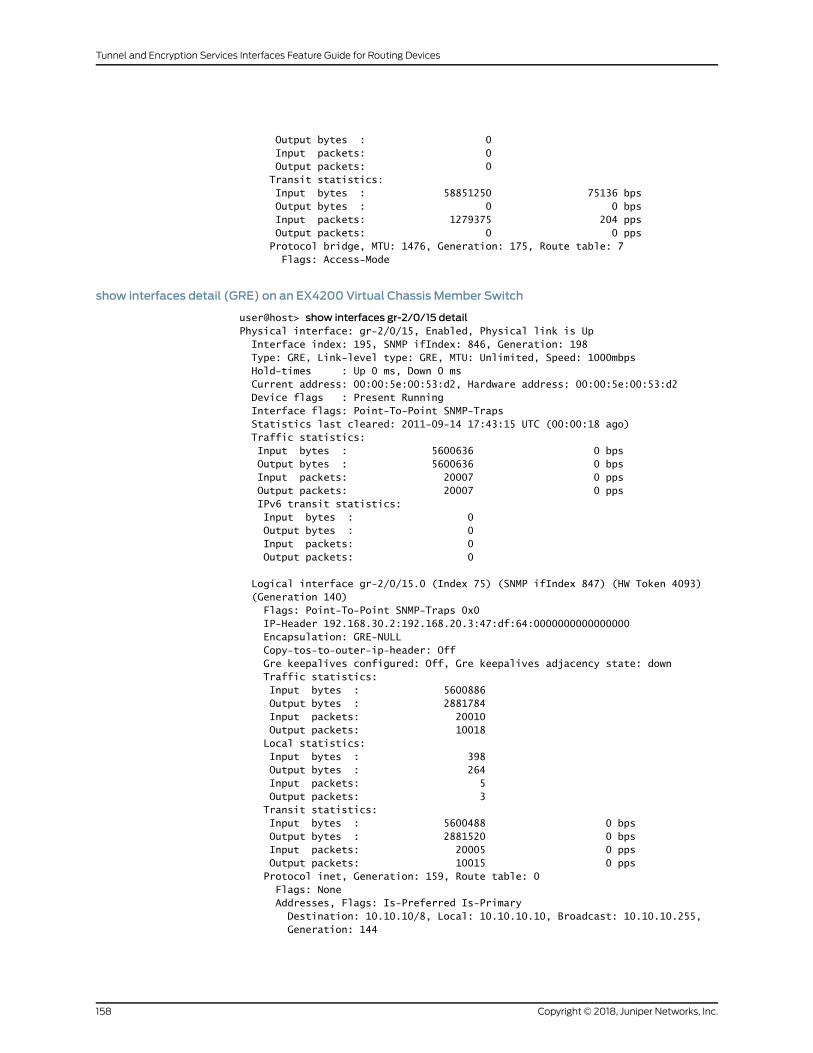
Output bytes : 0 Input packets: 0 Output packets: 0 Transit statistics: Input bytes : 58851250 75136 bps Output bytes : 0 0 bps Input packets: 1279375 204 pps Output packets: 0 0 pps Protocol bridge, MTU: 1476, Generation: 175, Route table: 7 Flags: Access-Mode
show interfaces detail (GRE) on an EX4200 Virtual Chassis Member Switch
user@host> show interfaces gr-2/0/15 detailPhysical interface: gr-2/0/15, Enabled, Physical link is Up Interface index: 195, SNMP ifIndex: 846, Generation: 198 Type: GRE, Link-level type: GRE, MTU: Unlimited, Speed: 1000mbps Hold-times : Up 0 ms, Down 0 ms Current address: 00:00:5e:00:53:d2, Hardware address: 00:00:5e:00:53:d2 Device flags : Present Running Interface flags: Point-To-Point SNMP-Traps Statistics last cleared: 2011-09-14 17:43:15 UTC (00:00:18 ago) Traffic statistics: Input bytes : 5600636 0 bps Output bytes : 5600636 0 bps Input packets: 20007 0 pps Output packets: 20007 0 pps IPv6 transit statistics: Input bytes : 0 Output bytes : 0 Input packets: 0 Output packets: 0
Logical interface gr-2/0/15.0 (Index 75) (SNMP ifIndex 847) (HW Token 4093) (Generation 140) Flags: Point-To-Point SNMP-Traps 0x0 IP-Header 192.168.30.2:192.168.20.3:47:df:64:0000000000000000 Encapsulation: GRE-NULL Copy-tos-to-outer-ip-header: Off Gre keepalives configured: Off, Gre keepalives adjacency state: down Traffic statistics: Input bytes : 5600886 Output bytes : 2881784 Input packets: 20010 Output packets: 10018 Local statistics: Input bytes : 398 Output bytes : 264 Input packets: 5 Output packets: 3 Transit statistics: Input bytes : 5600488 0 bps Output bytes : 2881520 0 bps Input packets: 20005 0 pps Output packets: 10015 0 pps Protocol inet, Generation: 159, Route table: 0 Flags: None Addresses, Flags: Is-Preferred Is-Primary Destination: 10.10.10/8, Local: 10.10.10.10, Broadcast: 10.10.10.255, Generation: 144
Copyright © 2018, Juniper Networks, Inc.158
Tunnel and Encryption Services Interfaces Feature Guide for Routing Devices
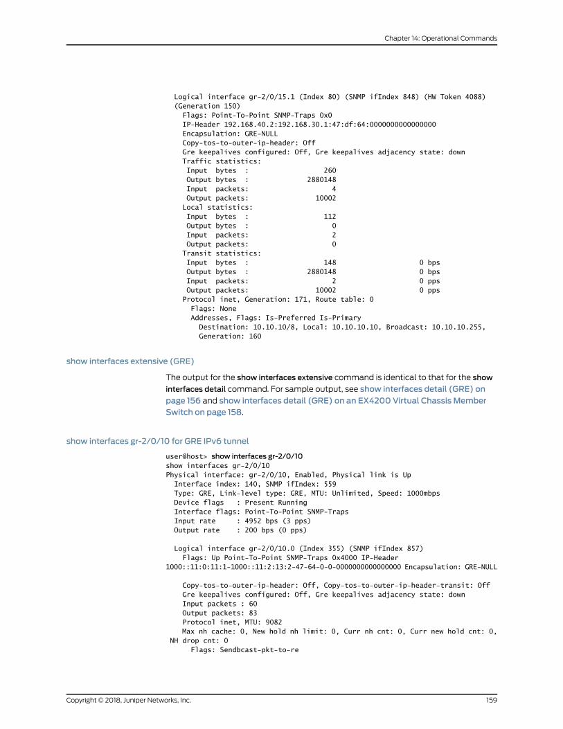
Logical interface gr-2/0/15.1 (Index 80) (SNMP ifIndex 848) (HW Token 4088) (Generation 150) Flags: Point-To-Point SNMP-Traps 0x0 IP-Header 192.168.40.2:192.168.30.1:47:df:64:0000000000000000 Encapsulation: GRE-NULL Copy-tos-to-outer-ip-header: Off Gre keepalives configured: Off, Gre keepalives adjacency state: down Traffic statistics: Input bytes : 260 Output bytes : 2880148 Input packets: 4 Output packets: 10002 Local statistics: Input bytes : 112 Output bytes : 0 Input packets: 2 Output packets: 0 Transit statistics: Input bytes : 148 0 bps Output bytes : 2880148 0 bps Input packets: 2 0 pps Output packets: 10002 0 pps Protocol inet, Generation: 171, Route table: 0 Flags: None Addresses, Flags: Is-Preferred Is-Primary Destination: 10.10.10/8, Local: 10.10.10.10, Broadcast: 10.10.10.255, Generation: 160
show interfaces extensive (GRE)
The output for the show interfaces extensive command is identical to that for the show
interfaces detail command. For sample output, see show interfaces detail (GRE) onpage 156 and show interfaces detail (GRE) on an EX4200 Virtual Chassis MemberSwitch on page 158.
show interfaces gr-2/0/10 for GRE IPv6 tunnel
user@host> show interfaces gr-2/0/10show interfaces gr-2/0/10 Physical interface: gr-2/0/10, Enabled, Physical link is Up Interface index: 140, SNMP ifIndex: 559 Type: GRE, Link-level type: GRE, MTU: Unlimited, Speed: 1000mbps Device flags : Present Running Interface flags: Point-To-Point SNMP-Traps Input rate : 4952 bps (3 pps) Output rate : 200 bps (0 pps)
Logical interface gr-2/0/10.0 (Index 355) (SNMP ifIndex 857) Flags: Up Point-To-Point SNMP-Traps 0x4000 IP-Header 1000::11:0:11:1-1000::11:2:13:2-47-64-0-0-0000000000000000 Encapsulation: GRE-NULL
Copy-tos-to-outer-ip-header: Off, Copy-tos-to-outer-ip-header-transit: Off Gre keepalives configured: Off, Gre keepalives adjacency state: down Input packets : 60 Output packets: 83 Protocol inet, MTU: 9082 Max nh cache: 0, New hold nh limit: 0, Curr nh cnt: 0, Curr new hold cnt: 0, NH drop cnt: 0 Flags: Sendbcast-pkt-to-re
159Copyright © 2018, Juniper Networks, Inc.
Chapter 14: Operational Commands

Addresses, Flags: Is-Preferred Is-Primary Destination: 14.0.13/24, Local: 14.0.13.1, Broadcast: 14.0.13.255 Protocol iso, MTU: 9082 Protocol inet6, MTU: 9082 Max nh cache: 0, New hold nh limit: 0, Curr nh cnt: 0, Curr new hold cnt: 0, NH drop cnt: 0 Addresses, Flags: Is-Preferred Is-Primary Destination: 1400::14:0:13:0/120, Local: 1400::14:0:13:1 Addresses, Flags: Is-Preferred Destination: fe80::/64, Local: fe80::2a0:a520:2875:4992 Protocol mpls, MTU: 9070, Maximum labels: 3 Flags: Is-Primary
Copyright © 2018, Juniper Networks, Inc.160
Tunnel and Encryption Services Interfaces Feature Guide for Routing Devices
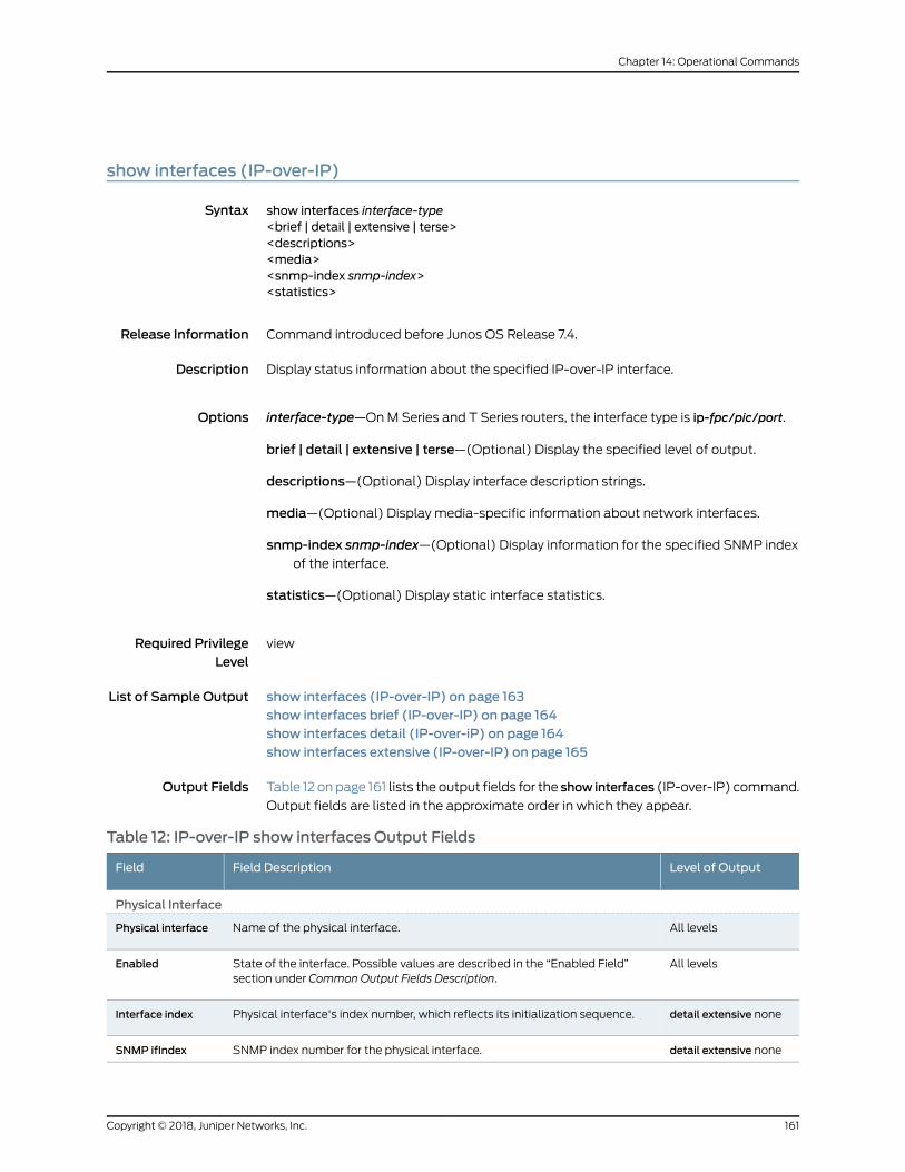
show interfaces (IP-over-IP)
Syntax show interfaces interface-type<brief | detail | extensive | terse><descriptions><media><snmp-index snmp-index><statistics>
Release Information Command introduced before Junos OS Release 7.4.
Description Display status information about the specified IP-over-IP interface.
Options interface-type—OnM Series and T Series routers, the interface type is ip-fpc/pic/port.
brief | detail | extensive | terse—(Optional) Display the specified level of output.
descriptions—(Optional) Display interface description strings.
media—(Optional) Display media-specific information about network interfaces.
snmp-index snmp-index—(Optional) Display information for the specified SNMP indexof the interface.
statistics—(Optional) Display static interface statistics.
Required PrivilegeLevel
view
List of Sample Output show interfaces (IP-over-IP) on page 163show interfaces brief (IP-over-IP) on page 164show interfaces detail (IP-over-iP) on page 164show interfaces extensive (IP-over-IP) on page 165
Output Fields Table 12 on page 161 lists the output fields for the show interfaces (IP-over-IP) command.
Output fields are listed in the approximate order in which they appear.
Table 12: IP-over-IP show interfaces Output Fields
Level of OutputField DescriptionField
Physical Interface
All levelsName of the physical interface.Physical interface
All levelsState of the interface. Possible values are described in the “Enabled Field”section under Common Output Fields Description.
Enabled
detail extensive nonePhysical interface's index number, which reflects its initialization sequence.Interface index
detail extensive noneSNMP index number for the physical interface.SNMP ifIndex
161Copyright © 2018, Juniper Networks, Inc.
Chapter 14: Operational Commands
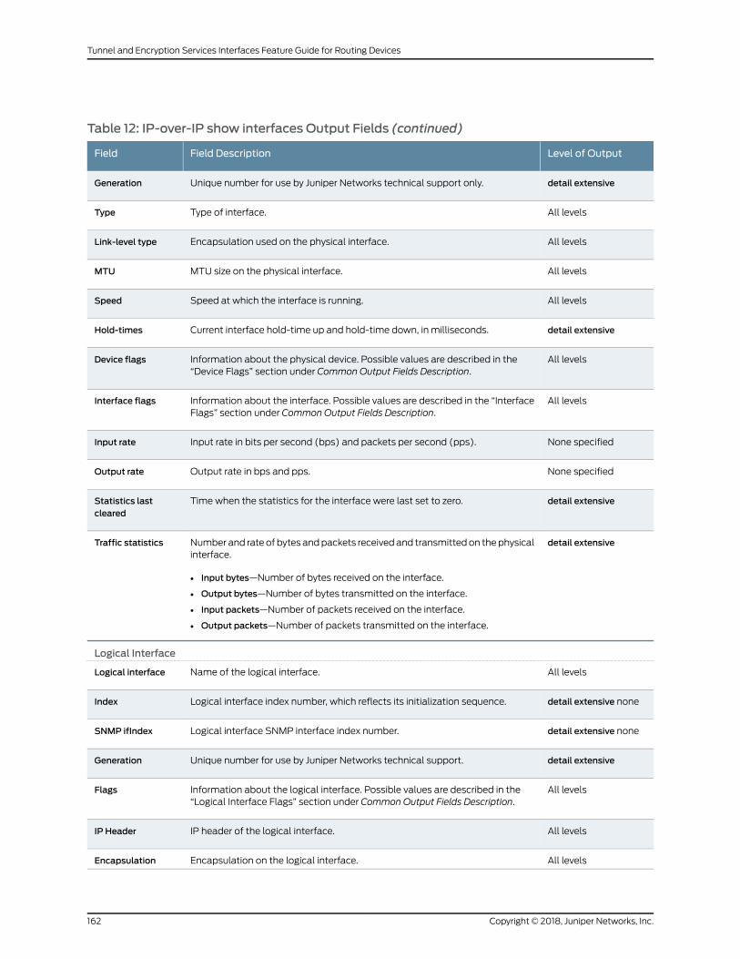
Table 12: IP-over-IP show interfaces Output Fields (continued)
Level of OutputField DescriptionField
detail extensiveUnique number for use by Juniper Networks technical support only.Generation
All levelsType of interface.Type
All levelsEncapsulation used on the physical interface.Link-level type
All levelsMTU size on the physical interface.MTU
All levelsSpeed at which the interface is running.Speed
detail extensiveCurrent interface hold-time up and hold-time down, in milliseconds.Hold-times
All levelsInformation about the physical device. Possible values are described in the“Device Flags” section under Common Output Fields Description.
Device flags
All levelsInformation about the interface. Possible values are described in the “InterfaceFlags” section under Common Output Fields Description.
Interface flags
None specifiedInput rate in bits per second (bps) and packets per second (pps).Input rate
None specifiedOutput rate in bps and pps.Output rate
detail extensiveTime when the statistics for the interface were last set to zero.Statistics lastcleared
detail extensiveNumber and rate of bytes andpackets receivedand transmittedon thephysicalinterface.
• Input bytes—Number of bytes received on the interface.
• Output bytes—Number of bytes transmitted on the interface.
• Input packets—Number of packets received on the interface.
• Output packets—Number of packets transmitted on the interface.
Traffic statistics
Logical Interface
All levelsName of the logical interface.Logical interface
detail extensive noneLogical interface index number, which reflects its initialization sequence.Index
detail extensive noneLogical interface SNMP interface index number.SNMP ifIndex
detail extensiveUnique number for use by Juniper Networks technical support.Generation
All levelsInformation about the logical interface. Possible values are described in the“Logical Interface Flags” section under Common Output Fields Description.
Flags
All levelsIP header of the logical interface.IP Header
All levelsEncapsulation on the logical interface.Encapsulation
Copyright © 2018, Juniper Networks, Inc.162
Tunnel and Encryption Services Interfaces Feature Guide for Routing Devices
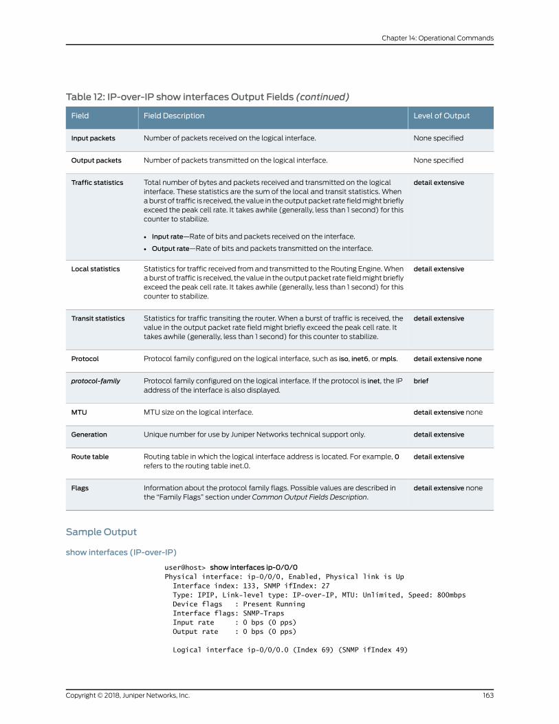
Table 12: IP-over-IP show interfaces Output Fields (continued)
Level of OutputField DescriptionField
None specifiedNumber of packets received on the logical interface.Input packets
None specifiedNumber of packets transmitted on the logical interface.Output packets
detail extensiveTotal number of bytes and packets received and transmitted on the logicalinterface. These statistics are the sum of the local and transit statistics. Whenaburst of traffic is received, the value in theoutputpacket rate fieldmightbrieflyexceed the peak cell rate. It takes awhile (generally, less than 1 second) for thiscounter to stabilize.
• Input rate—Rate of bits and packets received on the interface.
• Output rate—Rate of bits and packets transmitted on the interface.
Traffic statistics
detail extensiveStatistics for traffic received fromand transmitted to the Routing Engine.Whenaburst of traffic is received, the value in theoutputpacket rate fieldmightbrieflyexceed the peak cell rate. It takes awhile (generally, less than 1 second) for thiscounter to stabilize.
Local statistics
detail extensiveStatistics for traffic transiting the router. When a burst of traffic is received, thevalue in the output packet rate field might briefly exceed the peak cell rate. Ittakes awhile (generally, less than 1 second) for this counter to stabilize.
Transit statistics
detail extensive noneProtocol family configured on the logical interface, such as iso, inet6, ormpls.Protocol
briefProtocol family configured on the logical interface. If the protocol is inet, the IPaddress of the interface is also displayed.
protocol-family
detail extensive noneMTU size on the logical interface.MTU
detail extensiveUnique number for use by Juniper Networks technical support only.Generation
detail extensiveRouting table in which the logical interface address is located. For example, 0refers to the routing table inet.0.
Route table
detail extensive noneInformation about the protocol family flags. Possible values are described inthe “Family Flags” section under Common Output Fields Description.
Flags
Sample Output
show interfaces (IP-over-IP)
user@host> show interfaces ip-0/0/0Physical interface: ip-0/0/0, Enabled, Physical link is Up Interface index: 133, SNMP ifIndex: 27 Type: IPIP, Link-level type: IP-over-IP, MTU: Unlimited, Speed: 800mbps Device flags : Present Running Interface flags: SNMP-Traps Input rate : 0 bps (0 pps) Output rate : 0 bps (0 pps)
Logical interface ip-0/0/0.0 (Index 69) (SNMP ifIndex 49)
163Copyright © 2018, Juniper Networks, Inc.
Chapter 14: Operational Commands
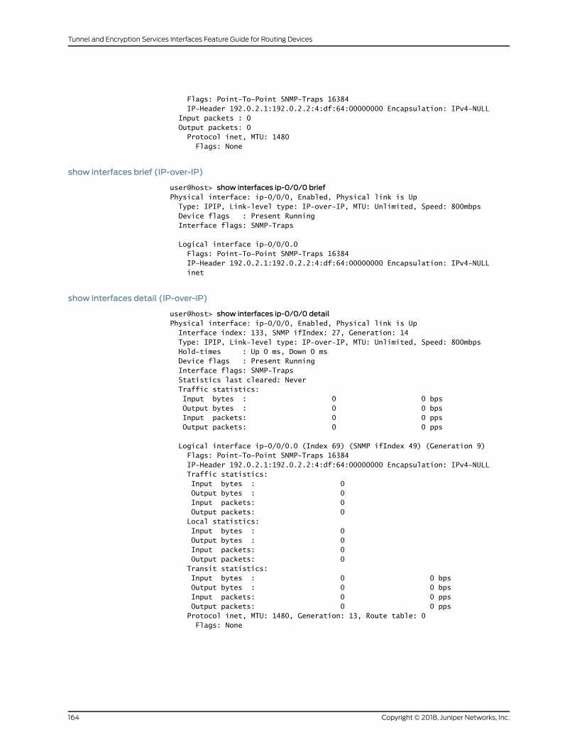
Flags: Point-To-Point SNMP-Traps 16384 IP-Header 192.0.2.1:192.0.2.2:4:df:64:00000000 Encapsulation: IPv4-NULL Input packets : 0 Output packets: 0 Protocol inet, MTU: 1480 Flags: None
show interfaces brief (IP-over-IP)
user@host> show interfaces ip-0/0/0 briefPhysical interface: ip-0/0/0, Enabled, Physical link is Up Type: IPIP, Link-level type: IP-over-IP, MTU: Unlimited, Speed: 800mbps Device flags : Present Running Interface flags: SNMP-Traps
Logical interface ip-0/0/0.0 Flags: Point-To-Point SNMP-Traps 16384 IP-Header 192.0.2.1:192.0.2.2:4:df:64:00000000 Encapsulation: IPv4-NULL inet
show interfaces detail (IP-over-iP)
user@host> show interfaces ip-0/0/0 detailPhysical interface: ip-0/0/0, Enabled, Physical link is Up Interface index: 133, SNMP ifIndex: 27, Generation: 14 Type: IPIP, Link-level type: IP-over-IP, MTU: Unlimited, Speed: 800mbps Hold-times : Up 0 ms, Down 0 ms Device flags : Present Running Interface flags: SNMP-Traps Statistics last cleared: Never Traffic statistics: Input bytes : 0 0 bps Output bytes : 0 0 bps Input packets: 0 0 pps Output packets: 0 0 pps
Logical interface ip-0/0/0.0 (Index 69) (SNMP ifIndex 49) (Generation 9) Flags: Point-To-Point SNMP-Traps 16384 IP-Header 192.0.2.1:192.0.2.2:4:df:64:00000000 Encapsulation: IPv4-NULL Traffic statistics: Input bytes : 0 Output bytes : 0 Input packets: 0 Output packets: 0 Local statistics: Input bytes : 0 Output bytes : 0 Input packets: 0 Output packets: 0 Transit statistics: Input bytes : 0 0 bps Output bytes : 0 0 bps Input packets: 0 0 pps Output packets: 0 0 pps Protocol inet, MTU: 1480, Generation: 13, Route table: 0 Flags: None
Copyright © 2018, Juniper Networks, Inc.164
Tunnel and Encryption Services Interfaces Feature Guide for Routing Devices

show interfaces extensive (IP-over-IP)
The output for the show interfaces extensive command is identical to that for the show
interfaces detail command. For sample output, see show interfaces detail (IP-over-iP)on page 164.
165Copyright © 2018, Juniper Networks, Inc.
Chapter 14: Operational Commands
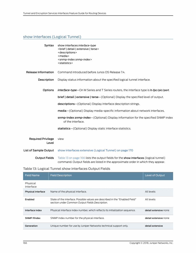
show interfaces (Logical Tunnel)
Syntax show interfaces interface-type<brief | detail | extensive | terse><descriptions><media><snmp-index snmp-index><statistics>
Release Information Command introduced before Junos OS Release 7.4.
Description Display status information about the specified logical tunnel interface.
Options interface-type—OnM Series and T Series routers, the interface type is lt-fpc/pic/port.
brief | detail | extensive | terse—(Optional) Display the specified level of output.
descriptions—(Optional) Display interface description strings.
media—(Optional) Display media-specific information about network interfaces.
snmp-index snmp-index—(Optional) Display information for the specified SNMP indexof the interface.
statistics—(Optional) Display static interface statistics.
Required PrivilegeLevel
view
List of Sample Output show interfaces extensive (Logical Tunnel) on page 170
Output Fields Table 13 on page 166 lists the output fields for the show interfaces (logical tunnel)
command. Output fields are listed in the approximate order in which they appear.
Table 13: Logical Tunnel show interfaces Output Fields
Level of OutputField DescriptionField Name
PhysicalInterface
All levelsName of the physical interface.Physical interface
All levelsState of the interface. Possible values are described in the “Enabled Field”section under Common Output Fields Description.
Enabled
detail extensive nonePhysical interface index number, which reflects its initialization sequence.Interface index
detail extensive noneSNMP index number for the physical interface.SNMP ifIndex
detail extensiveUnique number for use by Juniper Networks technical support only.Generation
Copyright © 2018, Juniper Networks, Inc.166
Tunnel and Encryption Services Interfaces Feature Guide for Routing Devices
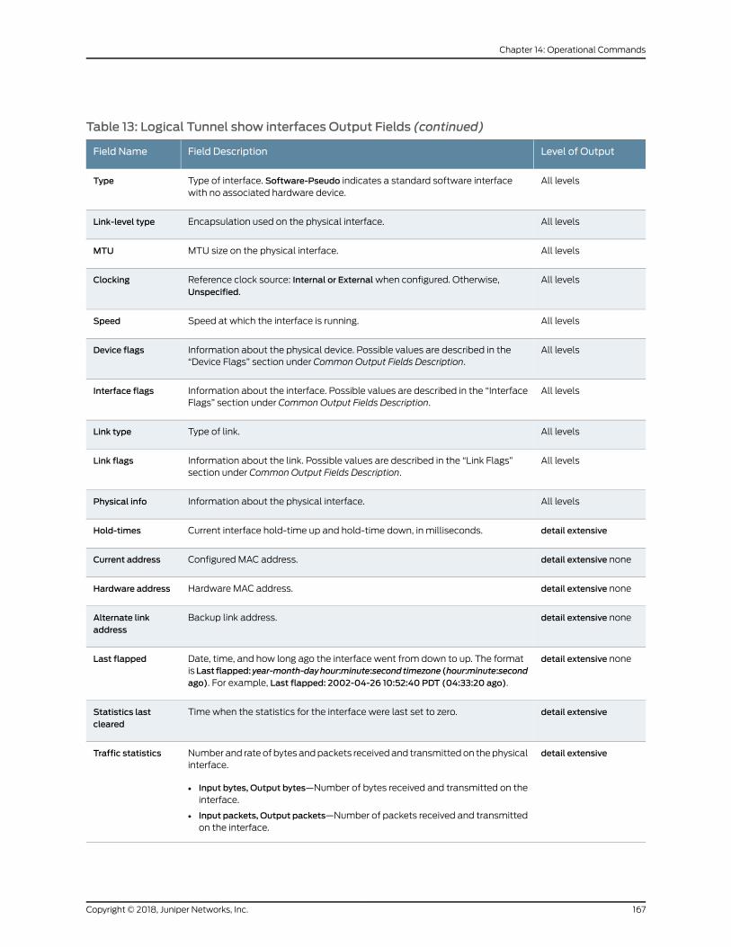
Table 13: Logical Tunnel show interfaces Output Fields (continued)
Level of OutputField DescriptionField Name
All levelsType of interface. Software-Pseudo indicates a standard software interfacewith no associated hardware device.
Type
All levelsEncapsulation used on the physical interface.Link-level type
All levelsMTU size on the physical interface.MTU
All levelsReference clock source: Internal or Externalwhen configured. Otherwise,Unspecified.
Clocking
All levelsSpeed at which the interface is running.Speed
All levelsInformation about the physical device. Possible values are described in the“Device Flags” section under Common Output Fields Description.
Device flags
All levelsInformation about the interface. Possible values are described in the “InterfaceFlags” section under Common Output Fields Description.
Interface flags
All levelsType of link.Link type
All levelsInformation about the link. Possible values are described in the “Link Flags”section under Common Output Fields Description.
Link flags
All levelsInformation about the physical interface.Physical info
detail extensiveCurrent interface hold-time up and hold-time down, in milliseconds.Hold-times
detail extensive noneConfigured MAC address.Current address
detail extensive noneHardware MAC address.Hardware address
detail extensive noneBackup link address.Alternate linkaddress
detail extensive noneDate, time, and how long ago the interface went from down to up. The formatisLast flapped:year-month-dayhour:minute:secondtimezone (hour:minute:secondago). For example, Last flapped: 2002-04-26 10:52:40 PDT (04:33:20 ago).
Last flapped
detail extensiveTime when the statistics for the interface were last set to zero.Statistics lastcleared
detail extensiveNumber and rate of bytes andpackets receivedand transmittedon thephysicalinterface.
• Input bytes, Output bytes—Number of bytes received and transmitted on theinterface.
• Input packets, Output packets—Number of packets received and transmittedon the interface.
Traffic statistics
167Copyright © 2018, Juniper Networks, Inc.
Chapter 14: Operational Commands

Table 13: Logical Tunnel show interfaces Output Fields (continued)
Level of OutputField DescriptionField Name
extensiveInput errors on the interface. The following paragraphs explain the counterswhosemeaning might not be obvious:
• Errors—Sum of the incoming frame aborts and FCS errors.
• Drops—Number of packets dropped by the input queue of the I/O ManagerASIC. If the interface is saturated, this number increments once for everypacket that is dropped by the ASIC's REDmechanism.
• Framing errors—Number of packets receivedwith an invalid frame checksum(FCS).
• Runts—Number of frames received that are smaller than the runt threshold.
• Giants—Number of frames received that are larger than the giant threshold.
• Policed discards—Number of frames that the incoming packet match codediscarded because they were not recognized or not of interest. Usually, thisfield reports protocols that the Junos OS does not handle.
• Resource errors—Sum of transmit drops.
Input errors
extensiveOutput errors on the interface. The following paragraphs explain the counterswhosemeaning might not be obvious:
• Carrier transitions—Number of times the interface has gone from down to up.This number does not normally increment quickly, increasing only when thecable is unplugged, the far-end system is powered down and then up, oranotherproblemoccurs. If thenumberof carrier transitions incrementsquickly(perhaps once every 10 seconds), the cable, the far-end system, or the PICis malfunctioning.
• Errors—Sum of the outgoing frame aborts and FCS errors.
• Drops—Number of packets dropped by the output queue of the I/OManagerASIC. If the interface is saturated, this number increments once for everypacket that is dropped by the ASIC's REDmechanism.
• MTU errors—Number of packets larger than the MTU threshold.
• Resource errors—Sum of transmit drops.
Output errors
Logical Interface
All levelsName of the logical interface.Logical interface
detail extensive noneLogical interface index number, which reflects its initialization sequence.Index
detail extensive noneSNMP interface index number.SNMP ifIndex
detail extensiveUnique number for use by Juniper Networks technical support only.Generation
All levelsInformation about the logical interface. Possible values are described in the“Logical Interface Flags” section under Common Output Fields Description.
Flags
All levelsEncapsulation on the logical interface.Encapsulation
Copyright © 2018, Juniper Networks, Inc.168
Tunnel and Encryption Services Interfaces Feature Guide for Routing Devices
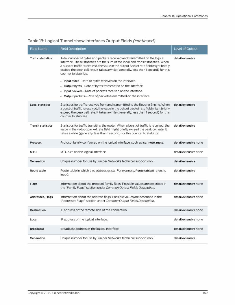
Table 13: Logical Tunnel show interfaces Output Fields (continued)
Level of OutputField DescriptionField Name
detail extensiveTotal number of bytes and packets received and transmitted on the logicalinterface. These statistics are the sum of the local and transit statistics. Whenaburst of traffic is received, the value in theoutputpacket rate fieldmightbrieflyexceed the peak cell rate. It takes awhile (generally, less than 1 second) for thiscounter to stabilize.
• Input bytes—Rate of bytes received on the interface.
• Output bytes—Rate of bytes transmitted on the interface.
• Input packets—Rate of packets received on the interface.
• Output packets—Rate of packets transmitted on the interface.
Traffic statistics
detail extensiveStatistics for traffic received fromand transmitted to the Routing Engine.Whenaburst of traffic is received, the value in theoutputpacket rate fieldmightbrieflyexceed the peak cell rate. It takes awhile (generally, less than 1 second) for thiscounter to stabilize.
Local statistics
detail extensiveStatistics for traffic transiting the router. When a burst of traffic is received, thevalue in the output packet rate field might briefly exceed the peak cell rate. Ittakes awhile (generally, less than 1 second) for this counter to stabilize.
Transit statistics
detail extensive noneProtocol family configured on the logical interface, such as iso, inet6,mpls.Protocol
detail extensive noneMTU size on the logical interface.MTU
detail extensiveUnique number for use by Juniper Networks technical support only.Generation
detail extensiveRoute table in which this address exists. For example, Route table:0 refers toinet.0.
Route table
detail extensive noneInformation about the protocol family flags. Possible values are described inthe “Family Flags” section under Common Output Fields Description.
Flags
detail extensive noneInformation about the address flags. Possible values are described in the“Addresses Flags” section under Common Output Fields Description.
Addresses, Flags
detail extensive noneIP address of the remote side of the connection.Destination
detail extensive noneIP address of the logical interface.Local
detail extensive noneBroadcast address of the logical interface.Broadcast
detail extensiveUnique number for use by Juniper Networks technical support only.Generation
169Copyright © 2018, Juniper Networks, Inc.
Chapter 14: Operational Commands
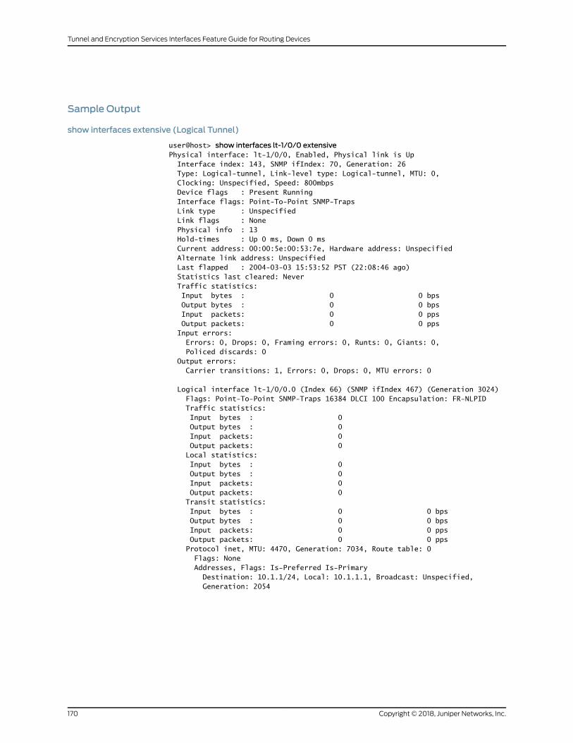
Sample Output
show interfaces extensive (Logical Tunnel)
user@host> show interfaces lt-1/0/0 extensivePhysical interface: lt-1/0/0, Enabled, Physical link is Up Interface index: 143, SNMP ifIndex: 70, Generation: 26 Type: Logical-tunnel, Link-level type: Logical-tunnel, MTU: 0, Clocking: Unspecified, Speed: 800mbps Device flags : Present Running Interface flags: Point-To-Point SNMP-Traps Link type : Unspecified Link flags : None Physical info : 13 Hold-times : Up 0 ms, Down 0 ms Current address: 00:00:5e:00:53:7e, Hardware address: Unspecified Alternate link address: Unspecified Last flapped : 2004-03-03 15:53:52 PST (22:08:46 ago) Statistics last cleared: Never Traffic statistics: Input bytes : 0 0 bps Output bytes : 0 0 bps Input packets: 0 0 pps Output packets: 0 0 pps Input errors: Errors: 0, Drops: 0, Framing errors: 0, Runts: 0, Giants: 0, Policed discards: 0 Output errors: Carrier transitions: 1, Errors: 0, Drops: 0, MTU errors: 0
Logical interface lt-1/0/0.0 (Index 66) (SNMP ifIndex 467) (Generation 3024) Flags: Point-To-Point SNMP-Traps 16384 DLCI 100 Encapsulation: FR-NLPID Traffic statistics: Input bytes : 0 Output bytes : 0 Input packets: 0 Output packets: 0 Local statistics: Input bytes : 0 Output bytes : 0 Input packets: 0 Output packets: 0 Transit statistics: Input bytes : 0 0 bps Output bytes : 0 0 bps Input packets: 0 0 pps Output packets: 0 0 pps Protocol inet, MTU: 4470, Generation: 7034, Route table: 0 Flags: None Addresses, Flags: Is-Preferred Is-Primary Destination: 10.1.1/24, Local: 10.1.1.1, Broadcast: Unspecified, Generation: 2054
Copyright © 2018, Juniper Networks, Inc.170
Tunnel and Encryption Services Interfaces Feature Guide for Routing Devices
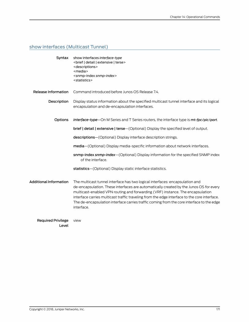
show interfaces (Multicast Tunnel)
Syntax show interfaces interface-type<brief | detail | extensive | terse><descriptions><media><snmp-index snmp-index><statistics>
Release Information Command introduced before Junos OS Release 7.4.
Description Display status information about the specified multicast tunnel interface and its logical
encapsulation and de-encapsulation interfaces.
Options interface-type—OnM Series and T Series routers, the interface type ismt-fpc/pic/port.
brief | detail | extensive | terse—(Optional) Display the specified level of output.
descriptions—(Optional) Display interface description strings.
media—(Optional) Display media-specific information about network interfaces.
snmp-index snmp-index—(Optional) Display information for the specified SNMP indexof the interface.
statistics—(Optional) Display static interface statistics.
Additional Information Themulticast tunnel interface has two logical interfaces: encapsulation and
de-encapsulation. These interfaces are automatically created by the Junos OS for every
multicast-enabled VPN routing and forwarding (VRF) instance. The encapsulation
interface carries multicast traffic traveling from the edge interface to the core interface.
The de-encapsulation interface carries traffic coming from the core interface to the edge
interface.
Required PrivilegeLevel
view
171Copyright © 2018, Juniper Networks, Inc.
Chapter 14: Operational Commands
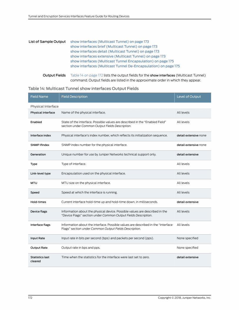
List of Sample Output show interfaces (Multicast Tunnel) on page 173show interfaces brief (Multicast Tunnel) on page 173show interfaces detail (Multicast Tunnel) on page 173show interfaces extensive (Multicast Tunnel) on page 173show interfaces (Multicast Tunnel Encapsulation) on page 175show interfaces (Multicast Tunnel De-Encapsulation) on page 175
Output Fields Table 14 on page 172 lists the output fields for the show interfaces (Multicast Tunnel)
command. Output fields are listed in the approximate order in which they appear.
Table 14: Multicast Tunnel show interfaces Output Fields
Level of OutputField DescriptionField Name
Physical Interface
All levelsName of the physical interface.Physical interface
All levelsState of the interface. Possible values are described in the “Enabled Field”section under Common Output Fields Description.
Enabled
detail extensive nonePhysical interface's index number, which reflects its initialization sequence.Interface index
detail extensive noneSNMP index number for the physical interface.SNMP ifIndex
detail extensiveUnique number for use by Juniper Networks technical support only.Generation
All levelsType of interface.Type
All levelsEncapsulation used on the physical interface.Link-level type
All levelsMTU size on the physical interface.MTU
All levelsSpeed at which the interface is running.Speed
detail extensiveCurrent interface hold-time up and hold-time down, in milliseconds.Hold-times
All levelsInformation about the physical device. Possible values are described in the“Device Flags” section under Common Output Fields Description.
Device flags
All levelsInformation about the interface. Possible values are described in the “InterfaceFlags” section under Common Output Fields Description.
Interface flags
None specifiedInput rate in bits per second (bps) and packets per second (pps).Input Rate
None specifiedOutput rate in bps and pps.Output Rate
detail extensiveTime when the statistics for the interface were last set to zero.Statistics lastcleared
Copyright © 2018, Juniper Networks, Inc.172
Tunnel and Encryption Services Interfaces Feature Guide for Routing Devices
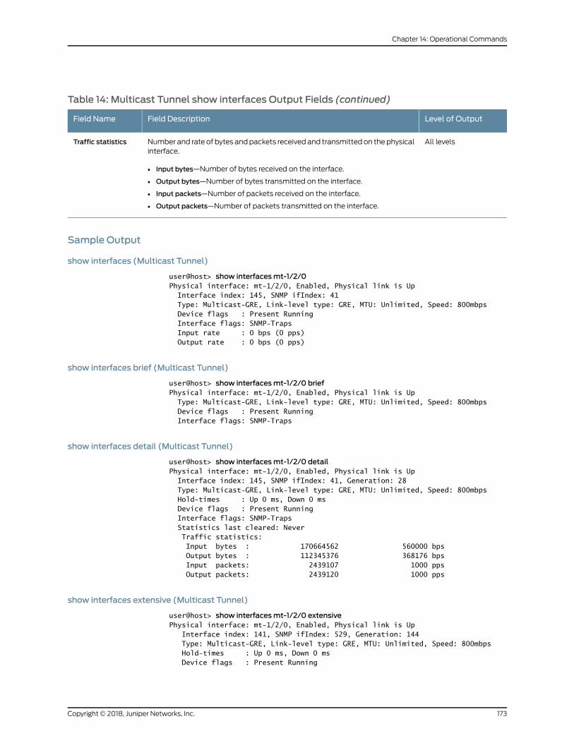
Table 14: Multicast Tunnel show interfaces Output Fields (continued)
Level of OutputField DescriptionField Name
All levelsNumber and rate of bytes andpackets receivedand transmittedon thephysicalinterface.
• Input bytes—Number of bytes received on the interface.
• Output bytes—Number of bytes transmitted on the interface.
• Input packets—Number of packets received on the interface.
• Output packets—Number of packets transmitted on the interface.
Traffic statistics
Sample Output
show interfaces (Multicast Tunnel)
user@host> show interfacesmt-1/2/0Physical interface: mt-1/2/0, Enabled, Physical link is Up Interface index: 145, SNMP ifIndex: 41 Type: Multicast-GRE, Link-level type: GRE, MTU: Unlimited, Speed: 800mbps Device flags : Present Running Interface flags: SNMP-Traps Input rate : 0 bps (0 pps) Output rate : 0 bps (0 pps)
show interfaces brief (Multicast Tunnel)
user@host> show interfacesmt-1/2/0 briefPhysical interface: mt-1/2/0, Enabled, Physical link is Up Type: Multicast-GRE, Link-level type: GRE, MTU: Unlimited, Speed: 800mbps Device flags : Present Running Interface flags: SNMP-Traps
show interfaces detail (Multicast Tunnel)
user@host> show interfacesmt-1/2/0 detailPhysical interface: mt-1/2/0, Enabled, Physical link is Up Interface index: 145, SNMP ifIndex: 41, Generation: 28 Type: Multicast-GRE, Link-level type: GRE, MTU: Unlimited, Speed: 800mbps Hold-times : Up 0 ms, Down 0 ms Device flags : Present Running Interface flags: SNMP-Traps Statistics last cleared: Never Traffic statistics: Input bytes : 170664562 560000 bps Output bytes : 112345376 368176 bps Input packets: 2439107 1000 pps Output packets: 2439120 1000 pps
show interfaces extensive (Multicast Tunnel)
user@host> show interfacesmt-1/2/0 extensivePhysical interface: mt-1/2/0, Enabled, Physical link is Up Interface index: 141, SNMP ifIndex: 529, Generation: 144 Type: Multicast-GRE, Link-level type: GRE, MTU: Unlimited, Speed: 800mbps Hold-times : Up 0 ms, Down 0 ms Device flags : Present Running
173Copyright © 2018, Juniper Networks, Inc.
Chapter 14: Operational Commands
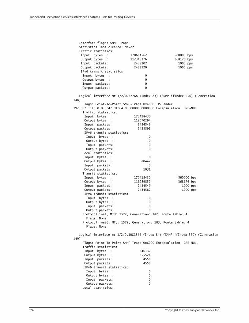
Interface flags: SNMP-Traps Statistics last cleared: Never Traffic statistics: Input bytes : 170664562 560000 bps Output bytes : 112345376 368176 bps Input packets: 2439107 1000 pps Output packets: 2439120 1000 pps IPv6 transit statistics: Input bytes : 0 Output bytes : 0 Input packets: 0 Output packets: 0
Logical interface mt-1/2/0.32768 (Index 83) (SNMP ifIndex 556) (Generation 148) Flags: Point-To-Point SNMP-Traps 0x4000 IP-Header 192.0.2.1:10.0.0.6:47:df:64:0000000800000000 Encapsulation: GRE-NULL Traffic statistics: Input bytes : 170418430 Output bytes : 112070294 Input packets: 2434549 Output packets: 2435593 IPv6 transit statistics: Input bytes : 0 Output bytes : 0 Input packets: 0 Output packets: 0 Local statistics: Input bytes : 0 Output bytes : 80442 Input packets: 0 Output packets: 1031 Transit statistics: Input bytes : 170418430 560000 bps Output bytes : 111989852 368176 bps Input packets: 2434549 1000 pps Output packets: 2434562 1000 pps IPv6 transit statistics: Input bytes : 0 Output bytes : 0 Input packets: 0 Output packets: 0 Protocol inet, MTU: 1572, Generation: 182, Route table: 4 Flags: None Protocol inet6, MTU: 1572, Generation: 183, Route table: 4 Flags: None
Logical interface mt-1/2/0.1081344 (Index 84) (SNMP ifIndex 560) (Generation 149) Flags: Point-To-Point SNMP-Traps 0x6000 Encapsulation: GRE-NULL Traffic statistics: Input bytes : 246132 Output bytes : 355524 Input packets: 4558 Output packets: 4558 IPv6 transit statistics: Input bytes : 0 Output bytes : 0 Input packets: 0 Output packets: 0 Local statistics:
Copyright © 2018, Juniper Networks, Inc.174
Tunnel and Encryption Services Interfaces Feature Guide for Routing Devices
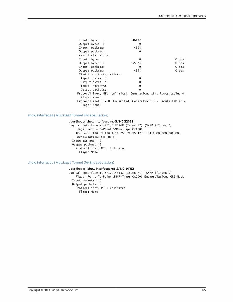
Input bytes : 246132 Output bytes : 0 Input packets: 4558 Output packets: 0 Transit statistics: Input bytes : 0 0 bps Output bytes : 355524 0 bps Input packets: 0 0 pps Output packets: 4558 0 pps IPv6 transit statistics: Input bytes : 0 Output bytes : 0 Input packets: 0 Output packets: 0 Protocol inet, MTU: Unlimited, Generation: 184, Route table: 4 Flags: None Protocol inet6, MTU: Unlimited, Generation: 185, Route table: 4 Flags: None
show interfaces (Multicast Tunnel Encapsulation)
user@host> show interfacesmt-3/1/0.32768Logical interface mt-3/1/0.32768 (Index 67) (SNMP ifIndex 0) Flags: Point-To-Point SNMP-Traps 0x4000 IP-Header 198.51.100.1:10.255.70.15:47:df:64:0000000800000000 Encapsulation: GRE-NULL Input packets : 0 Output packets: 2 Protocol inet, MTU: Unlimited Flags: None
show interfaces (Multicast Tunnel De-Encapsulation)
user@host> show interfacesmt-3/1/0.49152Logical interface mt-3/1/0.49152 (Index 74) (SNMP ifIndex 0) Flags: Point-To-Point SNMP-Traps 0x6000 Encapsulation: GRE-NULL Input packets : 0 Output packets: 2 Protocol inet, MTU: Unlimited Flags: None
175Copyright © 2018, Juniper Networks, Inc.
Chapter 14: Operational Commands
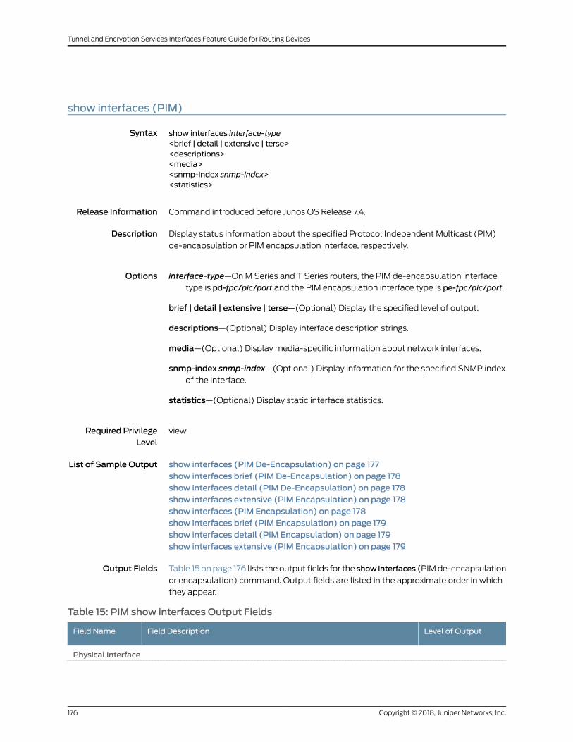
show interfaces (PIM)
Syntax show interfaces interface-type<brief | detail | extensive | terse><descriptions><media><snmp-index snmp-index><statistics>
Release Information Command introduced before Junos OS Release 7.4.
Description Display status information about the specified Protocol Independent Multicast (PIM)
de-encapsulation or PIM encapsulation interface, respectively.
Options interface-type—OnM Series and T Series routers, the PIM de-encapsulation interface
type is pd-fpc/pic/port and the PIM encapsulation interface type is pe-fpc/pic/port.
brief | detail | extensive | terse—(Optional) Display the specified level of output.
descriptions—(Optional) Display interface description strings.
media—(Optional) Display media-specific information about network interfaces.
snmp-index snmp-index—(Optional) Display information for the specified SNMP indexof the interface.
statistics—(Optional) Display static interface statistics.
Required PrivilegeLevel
view
List of Sample Output show interfaces (PIM De-Encapsulation) on page 177show interfaces brief (PIM De-Encapsulation) on page 178show interfaces detail (PIM De-Encapsulation) on page 178show interfaces extensive (PIM Encapsulation) on page 178show interfaces (PIM Encapsulation) on page 178show interfaces brief (PIM Encapsulation) on page 179show interfaces detail (PIM Encapsulation) on page 179show interfaces extensive (PIM Encapsulation) on page 179
Output Fields Table 15 onpage 176 lists the output fields for the show interfaces (PIMde-encapsulation
or encapsulation) command. Output fields are listed in the approximate order in which
they appear.
Table 15: PIM show interfaces Output Fields
Level of OutputField DescriptionField Name
Physical Interface
Copyright © 2018, Juniper Networks, Inc.176
Tunnel and Encryption Services Interfaces Feature Guide for Routing Devices
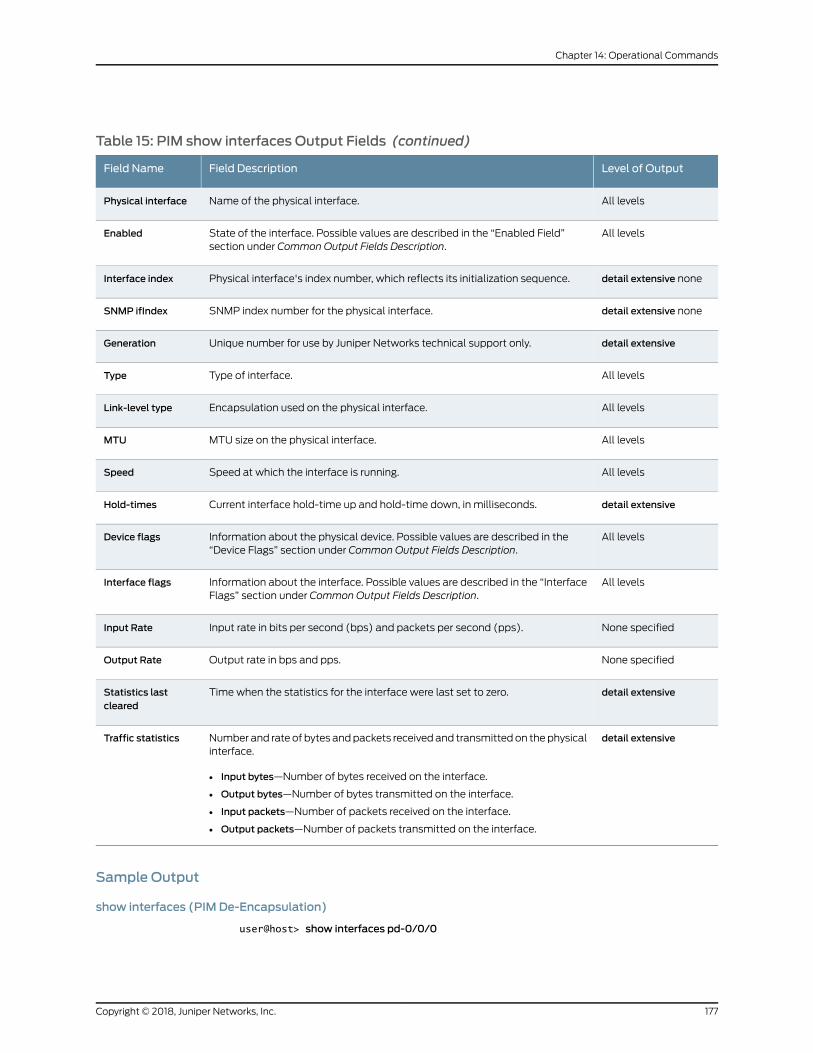
Table 15: PIM show interfaces Output Fields (continued)
Level of OutputField DescriptionField Name
All levelsName of the physical interface.Physical interface
All levelsState of the interface. Possible values are described in the “Enabled Field”section under Common Output Fields Description.
Enabled
detail extensive nonePhysical interface's index number, which reflects its initialization sequence.Interface index
detail extensive noneSNMP index number for the physical interface.SNMP ifIndex
detail extensiveUnique number for use by Juniper Networks technical support only.Generation
All levelsType of interface.Type
All levelsEncapsulation used on the physical interface.Link-level type
All levelsMTU size on the physical interface.MTU
All levelsSpeed at which the interface is running.Speed
detail extensiveCurrent interface hold-time up and hold-time down, in milliseconds.Hold-times
All levelsInformation about the physical device. Possible values are described in the“Device Flags” section under Common Output Fields Description.
Device flags
All levelsInformation about the interface. Possible values are described in the “InterfaceFlags” section under Common Output Fields Description.
Interface flags
None specifiedInput rate in bits per second (bps) and packets per second (pps).Input Rate
None specifiedOutput rate in bps and pps.Output Rate
detail extensiveTime when the statistics for the interface were last set to zero.Statistics lastcleared
detail extensiveNumber and rate of bytes andpackets receivedand transmittedon thephysicalinterface.
• Input bytes—Number of bytes received on the interface.
• Output bytes—Number of bytes transmitted on the interface.
• Input packets—Number of packets received on the interface.
• Output packets—Number of packets transmitted on the interface.
Traffic statistics
Sample Output
show interfaces (PIM De-Encapsulation)
user@host> show interfaces pd-0/0/0
177Copyright © 2018, Juniper Networks, Inc.
Chapter 14: Operational Commands
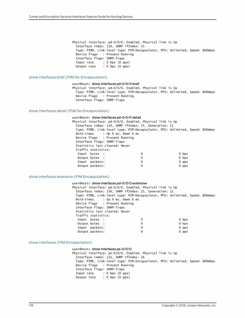
Physical interface: pd-0/0/0, Enabled, Physical link is Up Interface index: 130, SNMP ifIndex: 25 Type: PIMD, Link-level type: PIM-Decapsulator, MTU: Unlimited, Speed: 800mbps Device flags : Present Running Interface flags: SNMP-Traps Input rate : 0 bps (0 pps) Output rate : 0 bps (0 pps)
show interfaces brief (PIM De-Encapsulation)
user@host> show interfaces pd-0/0/0 briefPhysical interface: pd-0/0/0, Enabled, Physical link is Up Type: PIMD, Link-level type: PIM-Decapsulator, MTU: Unlimited, Speed: 800mbps Device flags : Present Running Interface flags: SNMP-Traps
show interfaces detail (PIM De-Encapsulation)
user@host> show interfaces pd-0/0/0 detailPhysical interface: pd-0/0/0, Enabled, Physical link is Up Interface index: 130, SNMP ifIndex: 25, Generation: 11 Type: PIMD, Link-level type: PIM-Decapsulator, MTU: Unlimited, Speed: 800mbps Hold-times : Up 0 ms, Down 0 ms Device flags : Present Running Interface flags: SNMP-Traps Statistics last cleared: Never Traffic statistics: Input bytes : 0 0 bps Output bytes : 0 0 bps Input packets: 0 0 pps Output packets: 0 0 pps
show interfaces extensive (PIM Encapsulation)
user@host> show interfaces pd-0/0/0 extensivePhysical interface: pd-0/0/0, Enabled, Physical link is Up Interface index: 130, SNMP ifIndex: 25, Generation: 11 Type: PIMD, Link-level type: PIM-Decapsulator, MTU: Unlimited, Speed: 800mbps Hold-times : Up 0 ms, Down 0 ms Device flags : Present Running Interface flags: SNMP-Traps Statistics last cleared: Never Traffic statistics: Input bytes : 0 0 bps Output bytes : 0 0 bps Input packets: 0 0 pps Output packets: 0 0 pps
show interfaces (PIM Encapsulation)
user@host> show interfaces pe-0/0/0Physical interface: pe-0/0/0, Enabled, Physical link is Up Interface index: 131, SNMP ifIndex: 26 Type: PIME, Link-level type: PIM-Encapsulator, MTU: Unlimited, Speed: 800mbps Device flags : Present Running Interface flags: SNMP-Traps Input rate : 0 bps (0 pps) Output rate : 0 bps (0 pps)
Copyright © 2018, Juniper Networks, Inc.178
Tunnel and Encryption Services Interfaces Feature Guide for Routing Devices
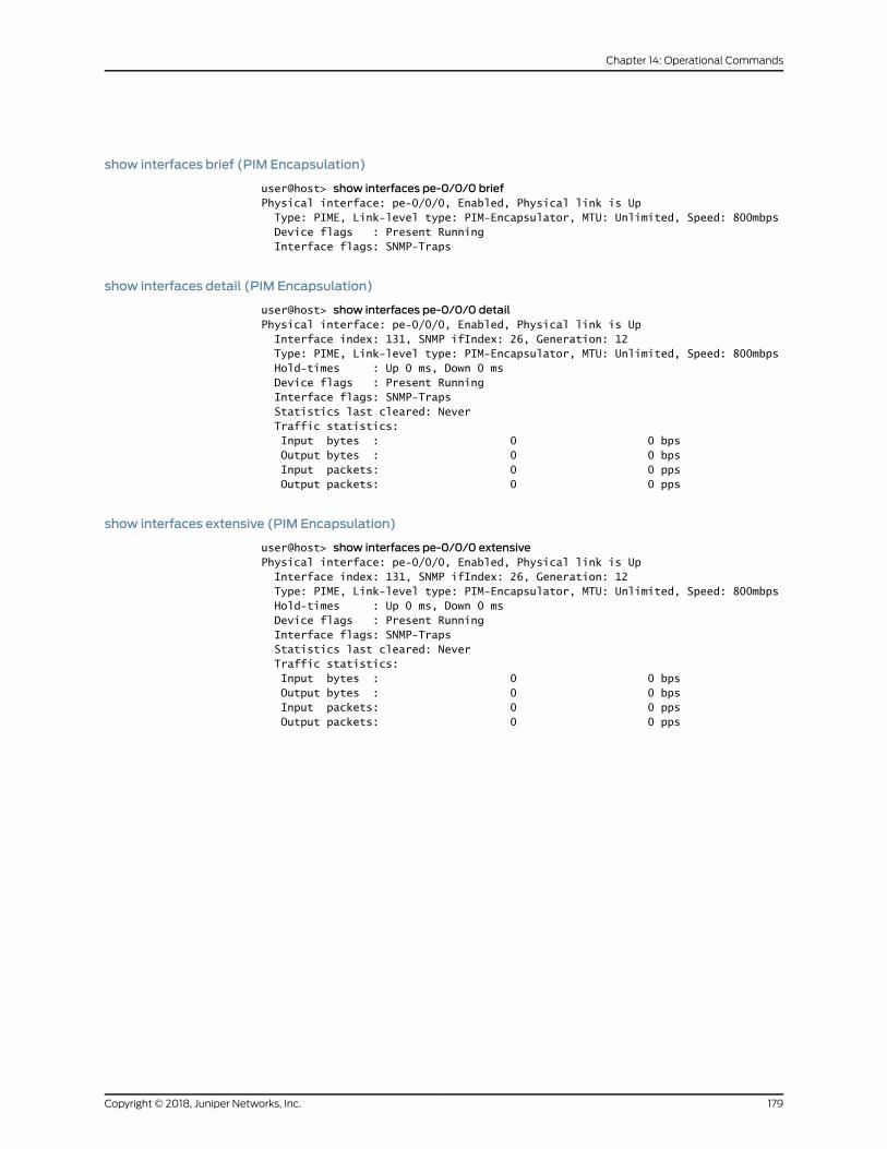
show interfaces brief (PIM Encapsulation)
user@host> show interfaces pe-0/0/0 briefPhysical interface: pe-0/0/0, Enabled, Physical link is Up Type: PIME, Link-level type: PIM-Encapsulator, MTU: Unlimited, Speed: 800mbps Device flags : Present Running Interface flags: SNMP-Traps
show interfaces detail (PIM Encapsulation)
user@host> show interfaces pe-0/0/0 detailPhysical interface: pe-0/0/0, Enabled, Physical link is Up Interface index: 131, SNMP ifIndex: 26, Generation: 12 Type: PIME, Link-level type: PIM-Encapsulator, MTU: Unlimited, Speed: 800mbps Hold-times : Up 0 ms, Down 0 ms Device flags : Present Running Interface flags: SNMP-Traps Statistics last cleared: Never Traffic statistics: Input bytes : 0 0 bps Output bytes : 0 0 bps Input packets: 0 0 pps Output packets: 0 0 pps
show interfaces extensive (PIM Encapsulation)
user@host> show interfaces pe-0/0/0 extensivePhysical interface: pe-0/0/0, Enabled, Physical link is Up Interface index: 131, SNMP ifIndex: 26, Generation: 12 Type: PIME, Link-level type: PIM-Encapsulator, MTU: Unlimited, Speed: 800mbps Hold-times : Up 0 ms, Down 0 ms Device flags : Present Running Interface flags: SNMP-Traps Statistics last cleared: Never Traffic statistics: Input bytes : 0 0 bps Output bytes : 0 0 bps Input packets: 0 0 pps Output packets: 0 0 pps
179Copyright © 2018, Juniper Networks, Inc.
Chapter 14: Operational Commands
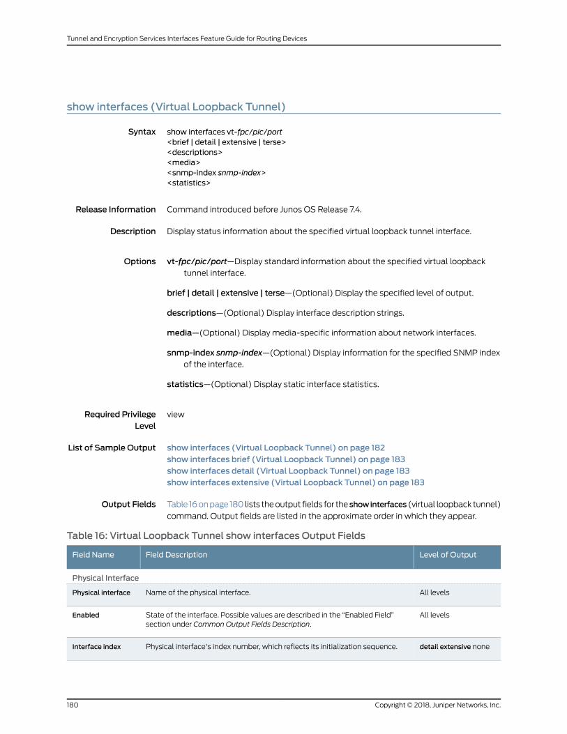
show interfaces (Virtual Loopback Tunnel)
Syntax show interfaces vt-fpc/pic/port<brief | detail | extensive | terse><descriptions><media><snmp-index snmp-index><statistics>
Release Information Command introduced before Junos OS Release 7.4.
Description Display status information about the specified virtual loopback tunnel interface.
Options vt-fpc/pic/port—Display standard information about the specified virtual loopbacktunnel interface.
brief | detail | extensive | terse—(Optional) Display the specified level of output.
descriptions—(Optional) Display interface description strings.
media—(Optional) Display media-specific information about network interfaces.
snmp-index snmp-index—(Optional) Display information for the specified SNMP indexof the interface.
statistics—(Optional) Display static interface statistics.
Required PrivilegeLevel
view
List of Sample Output show interfaces (Virtual Loopback Tunnel) on page 182show interfaces brief (Virtual Loopback Tunnel) on page 183show interfaces detail (Virtual Loopback Tunnel) on page 183show interfaces extensive (Virtual Loopback Tunnel) on page 183
Output Fields Table 16onpage 180 lists theoutput fields for the showinterfaces (virtual loopback tunnel)
command. Output fields are listed in the approximate order in which they appear.
Table 16: Virtual Loopback Tunnel show interfaces Output Fields
Level of OutputField DescriptionField Name
Physical Interface
All levelsName of the physical interface.Physical interface
All levelsState of the interface. Possible values are described in the “Enabled Field”section under Common Output Fields Description.
Enabled
detail extensive nonePhysical interface's index number, which reflects its initialization sequence.Interface index
Copyright © 2018, Juniper Networks, Inc.180
Tunnel and Encryption Services Interfaces Feature Guide for Routing Devices

Table 16: Virtual Loopback Tunnel show interfaces Output Fields (continued)
Level of OutputField DescriptionField Name
detail extensive noneSNMP index number for the physical interface.SNMP ifIndex
detail extensiveUnique number for use by Juniper Networks technical support only.Generation
All levelsType of interface.Type
All levelsEncapsulation used on the physical interface.Link-level type
All levelsMTU size on the physical interface.MTU
All levelsSpeed at which the interface is running.Speed
detail extensiveCurrent interface hold-time up and hold-time down, in milliseconds.Hold-times
All levelsInformation about the physical device. Possible values are described in the“Device Flags” section under Common Output Fields Description.
Device flags
None specifiedInput rate in bits per second (bps) and packets per second (pps).Input Rate
None specifiedOutput rate in bps and pps.Output Rate
detail extensiveTime when the statistics for the interface were last set to zero.Statistics lastcleared
detail extensiveNumber and rate of bytes andpackets receivedand transmittedon thephysicalinterface.
• Input bytes, Output bytes—Number of bytes received and transmitted on theinterface.
• Input packets, Output packets—Number of packets received and transmittedon the interface.
Traffic statistics
Logical Interface
All levelsName of the logical interface.Logical interface
detail extensive noneLogical interface index number, which reflects its initialization sequence.Index
detail extensive noneLogical interface SNMP interface index number.SNMP ifIndex
detail extensiveUnique number for use by Juniper Networks technical support only.Generation
All levelsInformation about the logical interface. Possible values are described in the“Interface Flags” section under Common Output Fields Description.
Flags
All levelsEncapsulation on the logical interface.Encapsulation
None specifiedNumber of packets received on the logical interface.Input packets
181Copyright © 2018, Juniper Networks, Inc.
Chapter 14: Operational Commands

Table 16: Virtual Loopback Tunnel show interfaces Output Fields (continued)
Level of OutputField DescriptionField Name
None specifiedNumber of packets transmitted on the logical interface.Output packets
All levelsBandwidth allotted to the logical interface, in kilobytes per second.Bandwidth
detail extensiveTotal number of bytes and packets received and transmitted on the logicalinterface. These statistics are the sum of the local and transit statistics. Whenaburst of traffic is received, the value in theoutputpacket rate fieldmightbrieflyexceed the peak cell rate. It takes awhile (generally, less than 1 second) for thiscounter to stabilize.
• Input bytes—Number of bytes received on the interface.
• Output bytes—Number of bytes transmitted on the interface.
• Input packets—Number of packets received on the interface.
• Output packets—Number of packets transmitted on the interface.
Traffic statistics
detail extensiveStatistics for traffic transiting the router. When a burst of traffic is received, thevalue in the output packet rate field might briefly exceed the peak cell rate. Ittakes awhile (generally, less than 1 second) for this counter to stabilize.
Transit statistics
briefProtocol family configuredon the logical interface. Possible valuesaredescribedin the “Family Flags” section under Common Output Fields Description.
protocol-family
detail extensive noneProtocol family configuredon the logical interface. Possible valuesaredescribedin the “Family Flags” section under Common Output Fields Description.
Protocol
detail extensive noneMaximum transmission unit size on the logical interface.MTU
detail extensive noneMaximum number of MPLS labels configured for the MPLS protocol family onthe logical interface.
Maximum labels
detail extensiveUnique number for use by Juniper Networks technical support only.Generation
detail extensiveRouting table in which the logical interface address is located. For example, 0refers to the routing table inet.0.
Route Table
detail extensive noneInformation about protocol family flags. Possible values are described in the“Family Flags” section under Common Output Fields Description.
Flags
Sample Output
show interfaces (Virtual Loopback Tunnel)
user@host> show interfaces vt-1/2/0Physical interface: vt-1/2/0, Enabled, Physical link is Up Interface index: 144, SNMP ifIndex: 40 Type: Loopback, Link-level type: Virtual-loopback-tunnel, MTU: Unlimited, Speed: 800mbps Device flags : Present Running Input rate : 0 bps (0 pps) Output rate : 0 bps (0 pps)
Copyright © 2018, Juniper Networks, Inc.182
Tunnel and Encryption Services Interfaces Feature Guide for Routing Devices
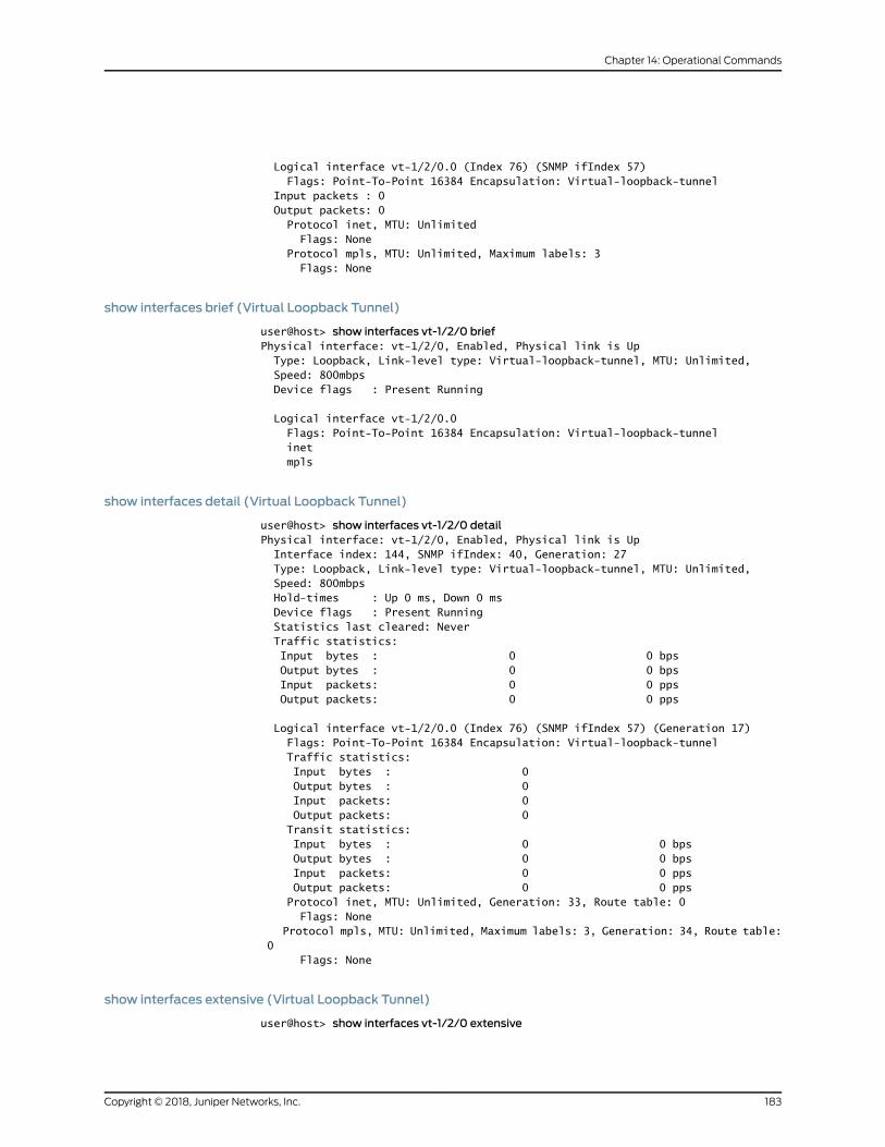
Logical interface vt-1/2/0.0 (Index 76) (SNMP ifIndex 57) Flags: Point-To-Point 16384 Encapsulation: Virtual-loopback-tunnel Input packets : 0 Output packets: 0 Protocol inet, MTU: Unlimited Flags: None Protocol mpls, MTU: Unlimited, Maximum labels: 3 Flags: None
show interfaces brief (Virtual Loopback Tunnel)
user@host> show interfaces vt-1/2/0 briefPhysical interface: vt-1/2/0, Enabled, Physical link is Up Type: Loopback, Link-level type: Virtual-loopback-tunnel, MTU: Unlimited, Speed: 800mbps Device flags : Present Running
Logical interface vt-1/2/0.0 Flags: Point-To-Point 16384 Encapsulation: Virtual-loopback-tunnel inet mpls
show interfaces detail (Virtual Loopback Tunnel)
user@host> show interfaces vt-1/2/0 detailPhysical interface: vt-1/2/0, Enabled, Physical link is Up Interface index: 144, SNMP ifIndex: 40, Generation: 27 Type: Loopback, Link-level type: Virtual-loopback-tunnel, MTU: Unlimited, Speed: 800mbps Hold-times : Up 0 ms, Down 0 ms Device flags : Present Running Statistics last cleared: Never Traffic statistics: Input bytes : 0 0 bps Output bytes : 0 0 bps Input packets: 0 0 pps Output packets: 0 0 pps
Logical interface vt-1/2/0.0 (Index 76) (SNMP ifIndex 57) (Generation 17) Flags: Point-To-Point 16384 Encapsulation: Virtual-loopback-tunnel Traffic statistics: Input bytes : 0 Output bytes : 0 Input packets: 0 Output packets: 0 Transit statistics: Input bytes : 0 0 bps Output bytes : 0 0 bps Input packets: 0 0 pps Output packets: 0 0 pps Protocol inet, MTU: Unlimited, Generation: 33, Route table: 0 Flags: None Protocol mpls, MTU: Unlimited, Maximum labels: 3, Generation: 34, Route table: 0 Flags: None
show interfaces extensive (Virtual Loopback Tunnel)
user@host> show interfaces vt-1/2/0 extensive
183Copyright © 2018, Juniper Networks, Inc.
Chapter 14: Operational Commands
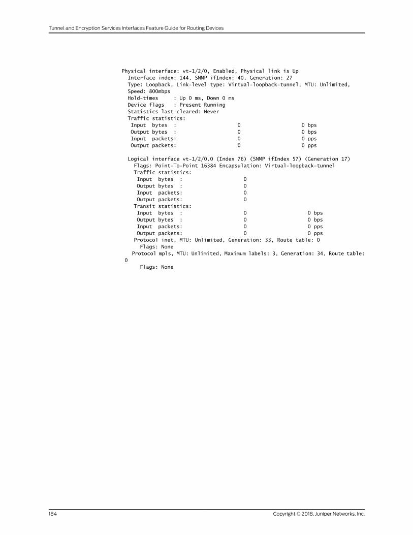
Physical interface: vt-1/2/0, Enabled, Physical link is Up Interface index: 144, SNMP ifIndex: 40, Generation: 27 Type: Loopback, Link-level type: Virtual-loopback-tunnel, MTU: Unlimited, Speed: 800mbps Hold-times : Up 0 ms, Down 0 ms Device flags : Present Running Statistics last cleared: Never Traffic statistics: Input bytes : 0 0 bps Output bytes : 0 0 bps Input packets: 0 0 pps Output packets: 0 0 pps
Logical interface vt-1/2/0.0 (Index 76) (SNMP ifIndex 57) (Generation 17) Flags: Point-To-Point 16384 Encapsulation: Virtual-loopback-tunnel Traffic statistics: Input bytes : 0 Output bytes : 0 Input packets: 0 Output packets: 0 Transit statistics: Input bytes : 0 0 bps Output bytes : 0 0 bps Input packets: 0 0 pps Output packets: 0 0 pps Protocol inet, MTU: Unlimited, Generation: 33, Route table: 0 Flags: None Protocol mpls, MTU: Unlimited, Maximum labels: 3, Generation: 34, Route table: 0 Flags: None
Copyright © 2018, Juniper Networks, Inc.184
Tunnel and Encryption Services Interfaces Feature Guide for Routing Devices
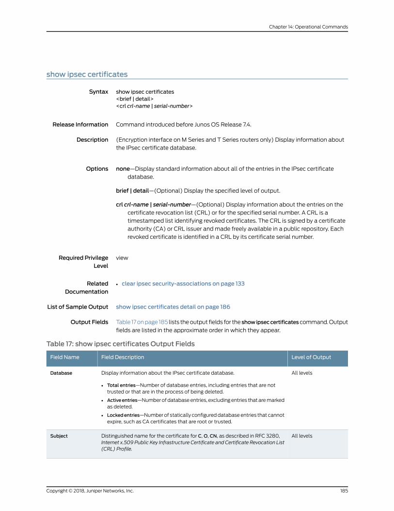
show ipsec certificates
Syntax show ipsec certificates<brief | detail><crl crl-name | serial-number>
Release Information Command introduced before Junos OS Release 7.4.
Description (Encryption interface on M Series and T Series routers only) Display information about
the IPsec certificate database.
Options none—Display standard information about all of the entries in the IPsec certificatedatabase.
brief | detail—(Optional) Display the specified level of output.
crl crl-name | serial-number—(Optional) Display information about the entries on thecertificate revocation list (CRL) or for the specified serial number. A CRL is a
timestamped list identifying revoked certificates. The CRL is signed by a certificate
authority (CA) or CRL issuer andmade freely available in a public repository. Each
revoked certificate is identified in a CRL by its certificate serial number.
Required PrivilegeLevel
view
RelatedDocumentation
clear ipsec security-associations on page 133•
List of Sample Output show ipsec certificates detail on page 186
Output Fields Table 17onpage 185 lists theoutput fields for the showipseccertificatescommand.Output
fields are listed in the approximate order in which they appear.
Table 17: show ipsec certificates Output Fields
Level of OutputField DescriptionField Name
All levelsDisplay information about the IPsec certificate database.
• Total entries—Number of database entries, including entries that are nottrusted or that are in the process of being deleted.
• Activeentries—Numberofdatabaseentries, excludingentries thataremarkedas deleted.
• Lockedentries—Numberof statically configureddatabaseentries that cannotexpire, such as CA certificates that are root or trusted.
Database
All levelsDistinguished name for the certificate for C,O, CN, as described in RFC 3280,Internet x.509 Public Key Infrastructure Certificate and Certificate Revocation List(CRL) Profile.
Subject
185Copyright © 2018, Juniper Networks, Inc.
Chapter 14: Operational Commands
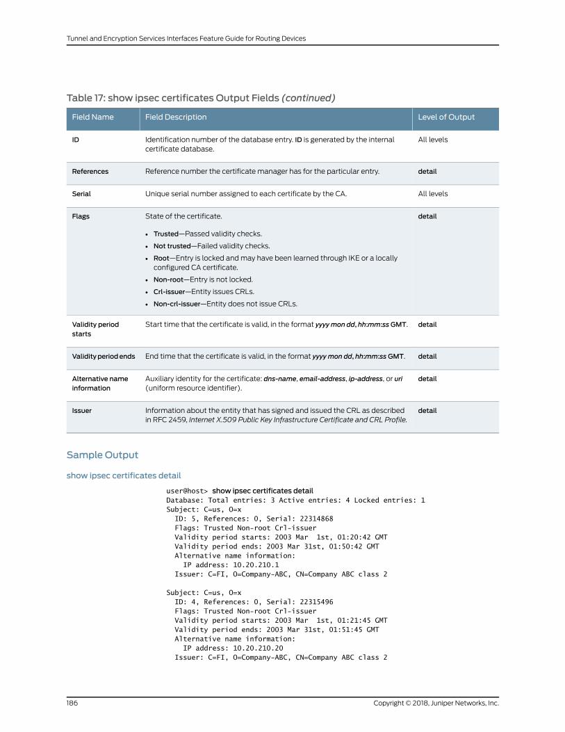
Table 17: show ipsec certificates Output Fields (continued)
Level of OutputField DescriptionField Name
All levelsIdentification number of the database entry. ID is generated by the internalcertificate database.
ID
detailReference number the certificate manager has for the particular entry.References
All levelsUnique serial number assigned to each certificate by the CA.Serial
detailState of the certificate.
• Trusted—Passed validity checks.
• Not trusted—Failed validity checks.
• Root—Entry is locked andmay have been learned through IKE or a locallyconfigured CA certificate.
• Non-root—Entry is not locked.
• Crl-issuer—Entity issues CRLs.
• Non-crl-issuer—Entity does not issue CRLs.
Flags
detailStart time that the certificate is valid, in the format yyyymon dd, hh:mm:ssGMT.Validity periodstarts
detailEnd time that the certificate is valid, in the format yyyymon dd, hh:mm:ssGMT.Validityperiodends
detailAuxiliary identity for the certificate: dns-name, email-address, ip-address, or uri(uniform resource identifier).
Alternative nameinformation
detailInformation about the entity that has signed and issued the CRL as describedin RFC 2459, Internet X.509 Public Key Infrastructure Certificate and CRL Profile.
Issuer
Sample Output
show ipsec certificates detail
user@host> show ipsec certificates detailDatabase: Total entries: 3 Active entries: 4 Locked entries: 1Subject: C=us, O=x ID: 5, References: 0, Serial: 22314868 Flags: Trusted Non-root Crl-issuer Validity period starts: 2003 Mar 1st, 01:20:42 GMT Validity period ends: 2003 Mar 31st, 01:50:42 GMT Alternative name information: IP address: 10.20.210.1 Issuer: C=FI, O=Company-ABC, CN=Company ABC class 2
Subject: C=us, O=x ID: 4, References: 0, Serial: 22315496 Flags: Trusted Non-root Crl-issuer Validity period starts: 2003 Mar 1st, 01:21:45 GMT Validity period ends: 2003 Mar 31st, 01:51:45 GMT Alternative name information: IP address: 10.20.210.20 Issuer: C=FI, O=Company-ABC, CN=Company ABC class 2
Copyright © 2018, Juniper Networks, Inc.186
Tunnel and Encryption Services Interfaces Feature Guide for Routing Devices

Subject: C=FI, O=SSH Company-ABC, CN=Company ABC class 2 ID: 1, References: 1, Serial: 1538512 Flags: Trusted Root Non-crl-issuer Validity period starts: 2001 Aug 1st, 07:08:32 GMT Validity period ends: 2004 Aug 1st, 07:08:32 GMT Alternative name information: Email address: [email protected] Issuer: C=FI, O=Company-ABC, CN=Company ABC class 2
187Copyright © 2018, Juniper Networks, Inc.
Chapter 14: Operational Commands

show ipsec redundancy
Syntax show ipsec redundancy (interface <es-fpc/pic/port> | security-associations <sa-name>)
Release Information Command introduced before Junos OS Release 7.4.
Description (Encryption interface on M Series and T Series routers only) Display information about
IPsec redundancy.
Options interface <es-fpc/pic/port>—Display information about all encryption interfaces, oroptionally, about a particular encryption interface.
security-associations <sa-name>—Display information about all remote tunnels, oroptionally, about a particular remote tunnel.
Required PrivilegeLevel
view
RelatedDocumentation
request ipsec switch on page 135•
List of Sample Output show ipsec redundancy interface on page 189show ipsec redundancy security-associations on page 189
Output Fields Table 18 on page 188 lists the output fields for the show ipsec redundancy command.
Output fields are listed in the approximate order in which they appear.
Table 18: show ipsec redundancy Output Fields
Field DescriptionField Name
Number of times a PIC switched between primary and backup interfaces, or the number of times thetunnel switched between the primary and remote peers since the software has been activated.
Failure counter
Name of the interface configured to be the primary interface.Primary interface '
Name of the interface configured to be the backup interface.Backup interface
State of the primary or backup interface can beActive,Offline, or Standby. Both ES PICs are initializedtoOffline. For primary and remote peers, State can be Active or Standby. Both peers are in a state ofStandby by default (there is not yet a connection between the two peers).
State
Name of the security association.Security association
Local IP address.Local IP
IP address of the configured primary remote peer.Primary remote IP
IP address of the configured backup remote peer.Backup remote IP
Copyright © 2018, Juniper Networks, Inc.188
Tunnel and Encryption Services Interfaces Feature Guide for Routing Devices
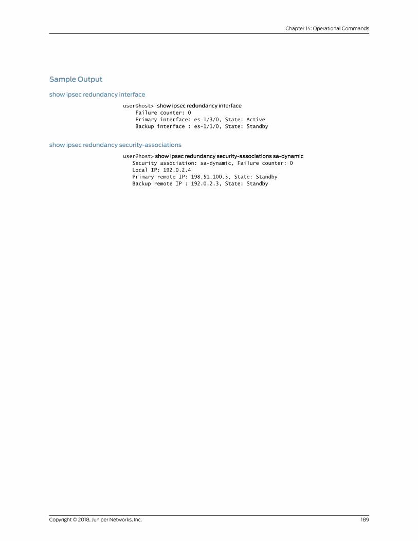
Sample Output
show ipsec redundancy interface
user@host> show ipsec redundancy interface Failure counter: 0 Primary interface: es-1/3/0, State: Active Backup interface : es-1/1/0, State: Standby
show ipsec redundancy security-associations
user@host> show ipsec redundancy security-associations sa-dynamic Security association: sa-dynamic, Failure counter: 0 Local IP: 192.0.2.4 Primary remote IP: 198.51.100.5, State: Standby Backup remote IP : 192.0.2.3, State: Standby
189Copyright © 2018, Juniper Networks, Inc.
Chapter 14: Operational Commands
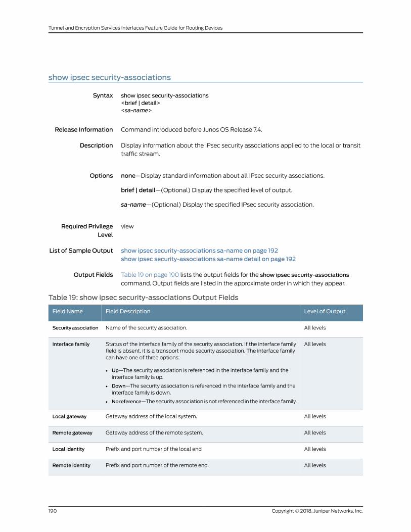
show ipsec security-associations
Syntax show ipsec security-associations<brief | detail><sa-name>
Release Information Command introduced before Junos OS Release 7.4.
Description Display information about the IPsec security associations applied to the local or transit
traffic stream.
Options none—Display standard information about all IPsec security associations.
brief | detail—(Optional) Display the specified level of output.
sa-name—(Optional) Display the specified IPsec security association.
Required PrivilegeLevel
view
List of Sample Output show ipsec security-associations sa-name on page 192show ipsec security-associations sa-name detail on page 192
Output Fields Table 19 on page 190 lists the output fields for the show ipsec security-associations
command. Output fields are listed in the approximate order in which they appear.
Table 19: show ipsec security-associations Output Fields
Level of OutputField DescriptionField Name
All levelsName of the security association.Securityassociation
All levelsStatus of the interface family of the security association. If the interface familyfield is absent, it is a transport mode security association. The interface familycan have one of three options:
• Up—The security association is referenced in the interface family and theinterface family is up.
• Down—The security association is referenced in the interface family and theinterface family is down.
• Noreference—Thesecurity association is not referenced in the interface family.
Interface family
All levelsGateway address of the local system.Local gateway
All levelsGateway address of the remote system.Remote gateway
All levelsPrefix and port number of the local endLocal identity
All levelsPrefix and port number of the remote end.Remote identity
Copyright © 2018, Juniper Networks, Inc.190
Tunnel and Encryption Services Interfaces Feature Guide for Routing Devices

Table 19: show ipsec security-associations Output Fields (continued)
Level of OutputField DescriptionField Name
All levelsDirection of the security association: inbound or outbound.Direction
All levelsValue of the security parameter index.SPI
All levelsValue of the auxiliary security parameter index.
• When the value is AH or ESP, AUX-SPI is always 0.
• When the value isAH+ESP, AUX-SPI is always a positive integer.
AUX-SPI
detailStatus of the security association:
• Installed—The security association is installed in the security associationdatabase. (For transportmode security associations, the value ofStatemustalways be Installed.)
• Not installed—The security association is not installed in the securityassociation database.
State
All levelsMode of the security association:
• transport—Protects single host-to-host protections.
• tunnel—Protects connections between security gateways.
Mode
All levelsType of security association:.
• manual—Security parameters require no negotiation. They are static, and areconfigured by the user.
• dynamic—Security parameters are negotiated by the IKE protocol. Dynamicsecurity associations are not supported in transport mode.
Type
All levelsProtocol supported:
• transportmode—Supports Encapsulation Security Protocol (ESP) orAuthentication Header (AH).
• tunnelmode—Supports ESP or AH+ESP.
Protocol
detailType of authentication used: hmac-md5-96, hmac-sha1-96, or None.Authentication
detailType of encryption used: des-cbc, 3des-csc, or None.Encryption
detail(dynamic output only) Each lifetime of a security association has two displayoptions, hard and soft, one of which must be present for a dynamic securityassociation. The hard lifetime specifies the lifetime of the SA. The soft lifetime,which is derived from the hard lifetime, informs the IPsec key managementsystem that the SA is about to expire. This allows the keymanagement systemto negotiate a new SA before the hard lifetime expires.
• Expires in seconds seconds—Number of seconds left until the securityassociation expires.
• Expires in kilobytes kilobytes—Number of kilobytes left until the securityassociation expires.
Soft lifetime
Hard lifetime
191Copyright © 2018, Juniper Networks, Inc.
Chapter 14: Operational Commands
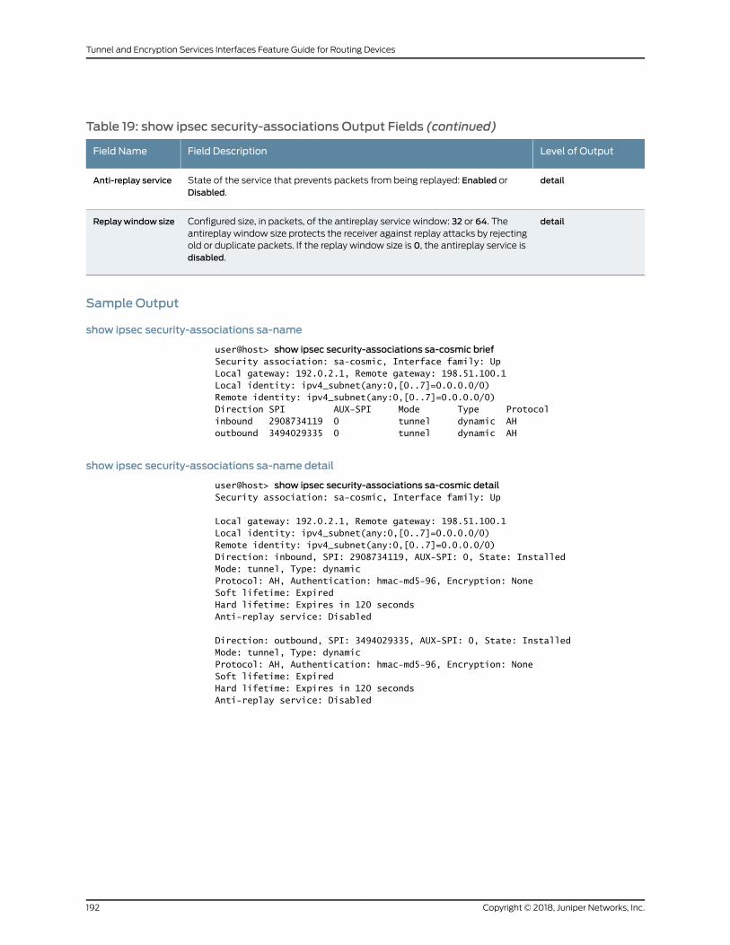
Table 19: show ipsec security-associations Output Fields (continued)
Level of OutputField DescriptionField Name
detailState of the service that prevents packets from being replayed: Enabled orDisabled.
Anti-replay service
detailConfigured size, in packets, of the antireplay service window: 32 or 64. Theantireplay window size protects the receiver against replay attacks by rejectingold or duplicate packets. If the replay window size is 0, the antireplay service isdisabled.
Replaywindowsize
Sample Output
show ipsec security-associations sa-name
user@host> show ipsec security-associations sa-cosmic briefSecurity association: sa-cosmic, Interface family: UpLocal gateway: 192.0.2.1, Remote gateway: 198.51.100.1Local identity: ipv4_subnet(any:0,[0..7]=0.0.0.0/0)Remote identity: ipv4_subnet(any:0,[0..7]=0.0.0.0/0)Direction SPI AUX-SPI Mode Type Protocolinbound 2908734119 0 tunnel dynamic AHoutbound 3494029335 0 tunnel dynamic AH
show ipsec security-associations sa-name detail
user@host> show ipsec security-associations sa-cosmic detailSecurity association: sa-cosmic, Interface family: Up
Local gateway: 192.0.2.1, Remote gateway: 198.51.100.1Local identity: ipv4_subnet(any:0,[0..7]=0.0.0.0/0)Remote identity: ipv4_subnet(any:0,[0..7]=0.0.0.0/0)Direction: inbound, SPI: 2908734119, AUX-SPI: 0, State: InstalledMode: tunnel, Type: dynamicProtocol: AH, Authentication: hmac-md5-96, Encryption: NoneSoft lifetime: ExpiredHard lifetime: Expires in 120 secondsAnti-replay service: Disabled
Direction: outbound, SPI: 3494029335, AUX-SPI: 0, State: InstalledMode: tunnel, Type: dynamicProtocol: AH, Authentication: hmac-md5-96, Encryption: NoneSoft lifetime: ExpiredHard lifetime: Expires in 120 secondsAnti-replay service: Disabled
Copyright © 2018, Juniper Networks, Inc.192
Tunnel and Encryption Services Interfaces Feature Guide for Routing Devices
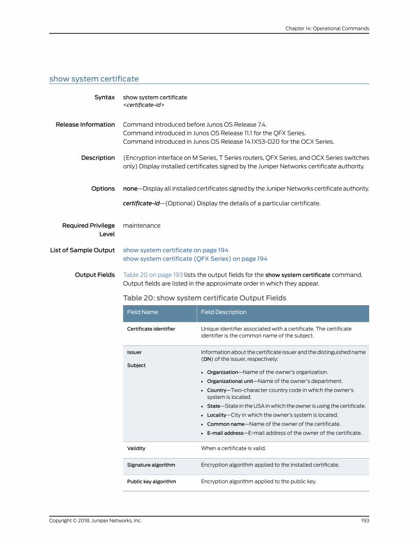
show system certificate
Syntax show system certificate<certificate-id>
Release Information Command introduced before Junos OS Release 7.4.
Command introduced in Junos OS Release 11.1 for the QFX Series.
Command introduced in Junos OS Release 14.1X53-D20 for the OCX Series.
Description (Encryption interface onMSeries, T Series routers, QFX Series, and OCX Series switches
only) Display installed certificates signed by the Juniper Networks certificate authority.
Options none—Displayall installedcertificates signedby the JuniperNetworkscertificateauthority.
certificate-id—(Optional) Display the details of a particular certificate.
Required PrivilegeLevel
maintenance
List of Sample Output show system certificate on page 194show system certificate (QFX Series) on page 194
Output Fields Table 20 on page 193 lists the output fields for the show system certificate command.
Output fields are listed in the approximate order in which they appear.
Table 20: show system certificate Output Fields
Field DescriptionField Name
Unique identifier associated with a certificate. The certificateidentifier is the common name of the subject.
Certificate identifier
Informationabout thecertificate issuer and thedistinguishedname(DN) of the issuer, respectively:
• Organization—Name of the owner’s organization.
• Organizational unit—Name of the owner's department.
• Country—Two-character country code in which the owner'ssystem is located.
• State—State in theUSA inwhich theowner is using thecertificate.
• Locality—City in which the owner’s system is located.
• Common name—Name of the owner of the certificate.
• E-mail address—E-mail address of the owner of the certificate.
Issuer
Subject
When a certificate is valid.Validity
Encryption algorithm applied to the installed certificate.Signature algorithm
Encryption algorithm applied to the public key.Public key algorithm
193Copyright © 2018, Juniper Networks, Inc.
Chapter 14: Operational Commands

Sample Output
show system certificate
user@host> show system certificateCertificate identifier: Dallas-v3 Issuer: Organization: Juniper Networks, Organizational unit: Juniper CA, Country: US, State: CA, Locality: Sunnyvale, Common name: Dallas CA, E-mail address:[email protected] Subject: Organization: Juniper Networks, Organizational unit: Juniper CA, Country: US, State: CA, Locality: Sunnyvale, Common name: Dallas-v3, E-mail address:[email protected]: Not before: Mar 13 03:23:25 2004 GMT Not after: Mar 24 03:23:25 2014 GMTSignature algorithm: sha1WithRSAEncryptionPublic key algorithm: dsaEncryption
show system certificate (QFX Series)
user@host> show system certificateCertificate identifier: Dallas-v3 Issuer: Organization: Juniper Networks, Organizational unit: Juniper CA, Country: US, State: CA, Locality: Sunnyvale, Common name: Dallas CA, E-mail address:[email protected] Subject: Organization: Juniper Networks, Organizational unit: Juniper CA, Country: US, State: CA, Locality: Sunnyvale, Common name: Dallas-v3, E-mail address:[email protected]: Not before: Mar 13 03:23:25 2004 GMT Not after: Mar 24 03:23:25 2014 GMTSignature algorithm: sha1WithRSAEncryptionPublic key algorithm: dsaEncryption
Copyright © 2018, Juniper Networks, Inc.194
Tunnel and Encryption Services Interfaces Feature Guide for Routing Devices