Embed Size (px)
Citation preview

7/25/2019 JS1034-XX-F06-0001. A1
http://slidepdf.com/reader/full/js1034-xx-f06-0001-a1 1/107

7/25/2019 JS1034-XX-F06-0001. A1
http://slidepdf.com/reader/full/js1034-xx-f06-0001-a1 2/107
CC ENERGY DEVELOPMENT S.A.L
(Oman Branch)
PROJECT
Farha & Saiwan AdequacyChecks
JOB NR. DOCUMENT NR. REV. DATE SHEET
JS1034 JS1034-XX-F06-0001 A1 Dec 09, 2015 2 of 107
TITLE
Adequacy Check Report
JS1034-XX-F06-0001.A1
SHEET REVISIONS SHEET REVISIONS

7/25/2019 JS1034-XX-F06-0001. A1
http://slidepdf.com/reader/full/js1034-xx-f06-0001-a1 3/107
CC ENERGY DEVELOPMENT S.A.L
(Oman Branch)
PROJECT
Farha & Saiwan AdequacyChecks
JOB NR. DOCUMENT NR. REV. DATE SHEET
JS1034 JS1034-XX-F06-0001 A1 Dec 09, 2015 3 of 107
TITLE
Adequacy Check Report
JS1034-XX-F06-0001.A1
CONTENTS
ABBREVIATIONS ..............................................................................................................................6
1 EXECUTIVE SUMMARY ...................................................................................................9
2 INTRODUCTION ............................................................................................................ 12
2.1 Reservoir Description & Production Background ........................................................ 12
2.2 Facilities Description ................................................................................................. 13
2.2.1 Farha Crude Treatment Facility..................................................................................................... 13
2.2.2 Saiwan Crude Treatment Facility .................................................................................................. 16
2.3 Station Production Capacities – Phase 2B ................................................................... 18
3 OBJECTIVE ................................................................................................................... 19
4 SCOPE OF WORK .......................................................................................................... 19
5 FARHA & SAIWAN PLANT PROCESS SIMULATIONS ........................................................ 19
5.1 Objective of Simulation ............................................................................................. 19
5.2 Farha Simulation Description ..................................................................................... 19
5.3 Saiwan Simulation Description .................................................................................. 22
5.4 Base Data and Assumptions ...................................................................................... 24
5.4.1 Compositions ................................................................................................................................ 24
5.4.2 Key Component Conditions .......................................................................................................... 28
5.5 Simulation Cases & Production Profile Scenarios ........................................................ 28
5.5.1 Simulation Cases ........................................................................................................................... 28
5.5.2 Production Profile Scenarios and Simulation Comparison ........................................................... 29
6 FARHA PROCESS EQUIPMENT ....................................................................................... 32
6.1 Inlet Manifold (201-XY-001B) .................................................................................... 32
6.2 Production Separators (201-VS-001A/B/C) ................................................................. 32
6.3 Dehydration (Heater Treaters 201-FY-001A/B/C)........................................................ 33
6.4 Oil Storage ................................................................................................................ 34

7/25/2019 JS1034-XX-F06-0001. A1
http://slidepdf.com/reader/full/js1034-xx-f06-0001-a1 4/107
CC ENERGY DEVELOPMENT S.A.L
(Oman Branch)
PROJECT
Farha & Saiwan AdequacyChecks
JOB NR. DOCUMENT NR. REV. DATE SHEET
JS1034 JS1034-XX-F06-0001 A1 Dec 09, 2015 4 of 107
TITLE
Adequacy Check Report
JS1034-XX-F06-0001.A1
6.5 Oil Export (Export Pumps & Pipeline) ......................................................................... 34
6.5.1 10” Pipeline Farha to Saiwan ........................................................................................................ 34
6.5.2 Oil Transfer Booster Pumps (221-PA-002A/B/C) & Oil Transfer Pumps (221-PA-001A/B/C) ....... 35
7 SAIWAN PROCESS EQUIPMENT ..................................................................................... 35
7.1 Inlet Manifold .......................................................................................................... 35
7.2 Production Separators (200-VS-001A/B) .................................................................... 36
7.3 Dehydration (Heater Treaters 200-FY-001A/B) ........................................................... 37
7.4 Oil Storage ................................................................................................................ 37
7.5 Oil Export (Export Pumps & Pipeline) ......................................................................... 38
7.5.1 16” Pipeline Saiwan to Alam ......................................................................................................... 38
7.5.2 Oil Transfer Booster Pumps (220-PA-002A/B/C) & Oil Transfer Pumps (220-PA-001A/B/C) ....... 38
8 FARHA UTILITIES (Excluding Electrical) .......................................................................... 39
8.1 Instrument Air System ............................................................................................... 39
8.2 Chemical Dosing Packages ......................................................................................... 39
8.3 Diesel Storage System ............................................................................................... 40
8.4 Flaring System........................................................................................................... 42
8.5 Nitrogen ................................................................................................................... 44
8.6 Utility Water ............................................................................................................. 45
8.7 Closed Drain System .................................................................................................. 45
9 SAIWAN UTILITIES (Excluding Electrical) ........................................................................ 46
9.1 Instrument Air System ............................................................................................... 46
9.2 Chemical Dosing Packages ......................................................................................... 46
9.3 Diesel Storage System ............................................................................................... 47
9.4 Flaring System........................................................................................................... 48
9.5 Nitrogen ................................................................................................................... 51
9.6 Utility Water ............................................................................................................. 52

7/25/2019 JS1034-XX-F06-0001. A1
http://slidepdf.com/reader/full/js1034-xx-f06-0001-a1 5/107
CC ENERGY DEVELOPMENT S.A.L
(Oman Branch)
PROJECT
Farha & Saiwan AdequacyChecks
JOB NR. DOCUMENT NR. REV. DATE SHEET
JS1034 JS1034-XX-F06-0001 A1 Dec 09, 2015 5 of 107
TITLE
Adequacy Check Report
JS1034-XX-F06-0001.A1
9.7 Closed Drain.............................................................................................................. 52
10 FARHA MAIN HEADERS................................................................................................. 53
11 SAIWAN MAIN HEADERS .............................................................................................. 53
12 FARHA & SAIWAN OVERALL PLOT PLAN (Mechanical) ................................................... 54
13 FARHA AND SAIWAN - C&A ADEQUACY CHECKS ........................................................... 60
13.1 Control and ESD System at Farha South Station.......................................................... 60
13.1.1 Existing DCS System at Farha South Station ................................................................................. 60
13.1.2 Existing ESD System at Farha South Station ................................................................................. 61
13.2 Adequacy Evaluation at Farha South Station .............................................................. 63
13.2.1 Existing DCS System at Farha South Station ................................................................................. 63
13.2.2 Existing ESD System at Farha South Station ................................................................................. 68
13.3 Available Space in FES Control Room for System Cabinet and HMI .............................. 77
13.4 Control and ESD System at Saiwan East Station .......................................................... 78
13.4.1 Existing DCS System at Saiwan East Station .................................................................................. 78
13.4.2 Existing ESD System at Saiwan East Station .................................................................................. 79
13.5 Adequacy Evaluation at Saiwan East Station .............................................................. 80
13.5.1 Existing DCS System at Saiwan East Station .................................................................................. 80
13.5.2 Existing ESD System at Saiwan East Station .................................................................................. 88
13.6 Available Space in SES Control Room for System Cabinet ........................................... 95
13.7 Control Valve Adequacy Check .................................................................................. 96
14 ELECTRICAL ADEQUACY CHECKS ................................................................................... 98
15 RECOMMENDATIONS & CONCLUSIONS (Process) ........................................................ 103
16 REFERENCES ............................................................................................................... 105
17 APPENDICES ............................................................................................................... 106

7/25/2019 JS1034-XX-F06-0001. A1
http://slidepdf.com/reader/full/js1034-xx-f06-0001-a1 6/107
CC ENERGY DEVELOPMENT S.A.L
(Oman Branch)
PROJECT
Farha & Saiwan AdequacyChecks
JOB NR. DOCUMENT NR. REV. DATE SHEET
JS1034 JS1034-XX-F06-0001 A1 Dec 09, 2015 6 of 107
TITLE
Adequacy Check Report
JS1034-XX-F06-0001.A1
ABBREVIATIONS
2oo3 2 out of 3
AP Atmospheric Pressure
BMS Burner Management System
BOPD Barrels of Oil per Day
BS&W Basic Sediment and WaterBVS Block Valve Station
BWPD Barrels of Water per Day
C&E Cause & Effects
CCED Consolidated Contractors Energy Division S.A.L (Oman Branch)
CCC Consolidated Contractor Group of Companies
DB Distribution Board
DCS Distributive Control System
DEP Design Engineering Practice
DG Diesel Generator
EPF Early Production Facility
ESD Emergency Shutdown
ESDV Emergency Shutdown Valve
FEED Front End Engineering Design
FG Fuel Gas
F&G Fire and Gas
FV Full Vacuum
GU Guideline
HAC Hazardous Area Classification
HMI Human Machine Interface
HP High Pressure
HV High Voltage
IA Instrument Air
ICS Integrated Control System
ISO International Standards Organisation

7/25/2019 JS1034-XX-F06-0001. A1
http://slidepdf.com/reader/full/js1034-xx-f06-0001-a1 7/107
CC ENERGY DEVELOPMENT S.A.L
(Oman Branch)
PROJECT
Farha & Saiwan AdequacyChecks
JOB NR. DOCUMENT NR. REV. DATE SHEET
JS1034 JS1034-XX-F06-0001 A1 Dec 09, 2015 7 of 107
TITLE
Adequacy Check Report
JS1034-XX-F06-0001.A1
JB Junction Box
KOD Knock Out Drum
LP Low Pressure
LPG Liquefied Petroleum Gas
LT Level Transmitter
LV Low Voltage
MCC Motor Control Centre
MMSCFD Millions of Standard Cubic Feet per Day
MOV Motor Operated Valve
MV Medium Voltage
MVA Mega Volt Ampere
NPSH Net Positive Suction Head
OCSP Operating Control and Safeguarding Philosophy
OHL Over Head LinePCV Pressure Control Valve
PDO Petroleum Development Oman
PESD Process Emergency Shut Down
PLC Programmable Logic Controller
PSV Pressure Safety Valve
P&ID Piping and Instrumentation Diagram
PT Pressure Transmitter
RO Restricted Orifice
RTU Remote Transmission Unit
RV Relief Valve
SCADA Supervisory Control and Data Acquisition
SDV Shut Down Valve
SP Specification
SR Switch Rack
TCV Temperature Control Valve
TP Tie-in Point

7/25/2019 JS1034-XX-F06-0001. A1
http://slidepdf.com/reader/full/js1034-xx-f06-0001-a1 8/107
CC ENERGY DEVELOPMENT S.A.L
(Oman Branch)
PROJECT
Farha & Saiwan AdequacyChecks
JOB NR. DOCUMENT NR. REV. DATE SHEET
JS1034 JS1034-XX-F06-0001 A1 Dec 09, 2015 8 of 107
TITLE
Adequacy Check Report
JS1034-XX-F06-0001.A1
TRV Thermal Relief Valve
TSV Thermal Safety Valve
TT Temperature Transmitter
UCP Unit Control Panel
UG Underground
UPS Uninterrupted Power Supply
WC Water Cut
VEC Value Engineering Centre

7/25/2019 JS1034-XX-F06-0001. A1
http://slidepdf.com/reader/full/js1034-xx-f06-0001-a1 9/107
CC ENERGY DEVELOPMENT S.A.L
(Oman Branch)
PROJECT
Farha & Saiwan AdequacyChecks
JOB NR. DOCUMENT NR. REV. DATE SHEET
JS1034 JS1034-XX-F06-0001 A1 Dec 09, 2015 9 of 107
TITLE
Adequacy Check Report
JS1034-XX-F06-0001.A1
1 EXECUTIVE SUMMARY
Adequacy checks were carried out by VEC at the order of CCED for the Phase 2B expansion of
Farha and Saiwan Crude Treatment Facilities.
The facilities at Farha and Saiwan each consist of one Separation Train (each Separation Train
consists of one Separator and one Heater Treater). Under Phase 2B, two additional Separation
Trains are to be added to the existing Farha Facilities and one additional Separation Train is to
be added to the existing Saiwan Facilities. Each additional train is to be a replica of the pre-
existing Separation Trains at Farha and Saiwan.
Majority of the items are found to be adequate however, some of the equipment was found
not to be adequate and require replacement or additional equipment in order to successfully
increase the production and satisfy Phase 2B of the expansion project. It is recommended that
the replacement/new equipment be designed and catered for during the detailed design of
Farha and Saiwan Phase 2B Expansion Project.
The tables on the following two pages show an overview of the items/equipment that was
considered as part of the scope of work under this adequacy study and found to be
inadequate.

7/25/2019 JS1034-XX-F06-0001. A1
http://slidepdf.com/reader/full/js1034-xx-f06-0001-a1 10/107
CC ENERGY DEVELOPMENT S.A.L
(Oman Branch)
PROJECT
Farha & Saiwan AdequacyChecks
JOB NR. DOCUMENT NR. REV. DATE SHEET
JS1034 JS1034-XX-F06-0001 A1 Dec 09, 2015 10 of 107
TITLE
Adequacy Check Report
JS1034-XX-F06-0001.A1
Farha Plant
Description Remarks
Storage Tanks
Inadequate based upon a 48 hour
production philosophy butadequate based on a 24 hr
retention of product.
Off-Spec Tank
Inadequate based on 24 hours
product retention.
Flare System
LP Flare Knockout Drum Inadequate
based on momentum criteria at
inlet nozzle.
Vessel Relief Valves
Heater Treater Relief Valves are
inadequate based on fire case
scenario.
Instrument Air System 1 more package is required
Chemical Dosing Packages Demulsifier Package is inadequate
Diesel Storage System
Diesel Storage Tank Capacity is
inadequate based on 15 days
consumption
Nitrogen
Inadequate based on worst case
scenario i.e. No Fuel Gas Available.
Plot Plan Spacing
Distance between 3rd
Train Heater
Treater and Separator is
inadequate.
Electrical InadequacyExpansion of switchgear room is not
possible.

7/25/2019 JS1034-XX-F06-0001. A1
http://slidepdf.com/reader/full/js1034-xx-f06-0001-a1 11/107
CC ENERGY DEVELOPMENT S.A.L
(Oman Branch)
PROJECT
Farha & Saiwan AdequacyChecks
JOB NR. DOCUMENT NR. REV. DATE SHEET
JS1034 JS1034-XX-F06-0001 A1 Dec 09, 2015 11 of 107
TITLE
Adequacy Check Report
JS1034-XX-F06-0001.A1
Saiwan Plant
Description Remarks
Separators
Operating outside of Operating
Envelope.
Storage Tanks Please see section 7.4 of Report
Export Pumps
Export Booster Pumps
Flare System
LP Flare Knockout Drum Inadequate
based on momentum criteria at
inlet nozzle. Also, Production
Separator Train 1 Tailpipe Mach
Number is too high.
Vessel Relief Valves
1st Train Production Separator and
2nd Train Heater Treater Relief
Valves are inadequate for the firecase scenario.
Diesel Storage System
Heater Treater Diesel Day Tank is
not adequate based on a 24 hours
supply
Nitrogen
Inadequate based on worst case
scenario i.e. No Fuel Gas Available.
Plot Plan Spacing
Distance between Diesel Unloading
Pump and Diesel Storage Tank is in
adequate. Spacing between the
new 2nd
Train Separator and Heater
Treater is not adequate.
For details, please reference the relevant sections of this Study Report alongside appendices.
7/25/2019 JS1034-XX-F06-0001. A1
http://slidepdf.com/reader/full/js1034-xx-f06-0001-a1 12/107
CC ENERGY DEVELOPMENT S.A.L
(Oman Branch)
PROJECT
Farha & Saiwan AdequacyChecks
JOB NR. DOCUMENT NR. REV. DATE SHEET
JS1034 JS1034-XX-F06-0001 A1 Dec 09, 2015 12 of 107
TITLE
Adequacy Check Report
JS1034-XX-F06-0001.A1
2 INTRODUCTION
2.1 Reservoir Description & Production Background
Consolidated Contractors Energy Division S.A.L. (CCED) is an upstream oil and gas exploration
and production company with operations in the Sultanate of Oman. CCED is part of the larger
Consolidated Contractors Group of Companies (CCC), a world-class engineering and
contracting conglomerate specialized in the construction of upstream oil and gas processing
facilities, refineries and petrochemical plants. It established its operation in Oman in October
2007 with the acquisition of 50 % interest in Blocks 3 and 4, situated in the south eastern belt
in Oman and covers an area of approximately 29,000 square kilometres.
Currently, there are treatment facilities for well-produced fluids at Farha and Saiwan locations
and a crude storage and custody metering arrangement at Alam Station (CCED) from where
the crude is transported to PDO Qarn Alam Station via an 8” PDO oil pipeline. Farha Crude
Treatment Facility is served by Farha South Wells and stabilised crude from Farha EPF is
transferred directly to the Farha Crude Oil Storage Tanks (221-TA-001A/B) from where the
stabilised Farha & Farha EPF crude is exported to Saiwan Crude Oil Storage Tanks (220-TA-
001A/B) via a 10” Export Pipeline. The Saiwan Crude Treatment Facility is served by Saiwan
East Wells and the Saiwan stabilised crude is exported from the Saiwan Crude Oil Storage
Tanks (220-TA-001A/B) along with the Farha stabilised crude to Alam Station which is
approximately 67 kms away from Saiwan East via a 16” Export Pipeline. Custody metering
takes place at Alam Station from where the crude is sent to PDO Qarn Alam Station via an 8”
PDO oil pipeline. Farha and Saiwan fields are approximately 50 kms apart from one another.
The above facilities were developed as part of Phase 2A of the reservoir exploitation program
and the facilities were designed for a maximum oil flow of 5,000 BOPD from Farha wells and a
maximum oil flow of 5,000 BOPD from Saiwan East wells. It was expected that for the future,
the maximum oil production from both Farha and Saiwan wells was to be 10,000 BOPD each.
The increased capacity of each treatment facility is covered under Phase 2B of the reservoir
exploitation program which is currently being carried out. Phase 2B will see additional process
units and utilities to handle the increased production which CCED wishes to achieve from both
Farha and Saiwan East wells. As part of Phase 2B, well produced fluids being treated at Farha

7/25/2019 JS1034-XX-F06-0001. A1
http://slidepdf.com/reader/full/js1034-xx-f06-0001-a1 13/107
CC ENERGY DEVELOPMENT S.A.L
(Oman Branch)
PROJECT
Farha & Saiwan AdequacyChecks
JOB NR. DOCUMENT NR. REV. DATE SHEET
JS1034 JS1034-XX-F06-0001 A1 Dec 09, 2015 13 of 107
TITLE
Adequacy Check Report
JS1034-XX-F06-0001.A1
EPF will be re-routed for treatment at Farha Crude Treatment Facility along with Farha South
Wells Produced Fluids.
In addition to the increased production from Farha and Saiwan wells, CCED wishes to utilise
the crude storage and export facilities at Saiwan Plant to handle stabilised crude from EPFs of
a third newly developed reservoir by the name of SHAHD. The maximum crude production for
all SHAHD EPFs excluding EPF locations “H” and “I” is 30,000 BOPD. Produced well fluids fromEPF locations “H” and “I” will be processed using the second Saiwan Separation Train which is
part of the additional units envisaged for Phase 2B of the reservoir exploitation program. In
the future, further wells are expected to be drilled and brought online for the SHAHD reservoir
and processed using the second Saiwan Separation Train up to a maximum oil flow of 10,000
BOPD.
The facilities at Farha and Saiwan each consist of one Separation Train (each Separation Train
consists of one Separator and one Heater Treater). Under Phase 2B, two additional Separation
Trains are to be added to the existing Farha Facilities and one additional Separation Train is to
be added to the existing Saiwan Facilities. Each additional Train is to be a replica of the pre-
existing Separation Trains at Farha and Saiwan.
2.2 Facilities Description
2.2.1 Farha Crude Treatment Facility
The Farha Plant is a sweet facility and has two Inlet Manifolds 201-XY-001A and 201-XY-001B.
Inlet Manifold (201-XY-001A) currently serves Farha EPF but has a provision for routing the
produced well fluids to the Inlet Manifold (201-XY-001B) which serves the main Farha Plant.
This arrangement is necessary as the produced well fluids being treated at Farha EPF will be
required to be re-routed to the main Farha Plant under Phase 2B.
Under Phase 2B, the produced well fluids are to be routed to the Production Separators (201-
VS-001A/B/C) (Trains 1, 2 and 3) where separation takes place. The separator produced water
is routed to the Evaporation Pond (591-TM-001/002) and the produced crude oil is routed to
the relevant Heater Treater (201-FY-001A/B/C) for dehydration via heat treatment and further

7/25/2019 JS1034-XX-F06-0001. A1
http://slidepdf.com/reader/full/js1034-xx-f06-0001-a1 14/107
CC ENERGY DEVELOPMENT S.A.L
(Oman Branch)
PROJECT
Farha & Saiwan AdequacyChecks
JOB NR. DOCUMENT NR. REV. DATE SHEET
JS1034 JS1034-XX-F06-0001 A1 Dec 09, 2015 14 of 107
TITLE
Adequacy Check Report
JS1034-XX-F06-0001.A1
separation. Each separation train is served by a dedicated Heater Treater unit. The produced
gas from the Production Separators (201-VS-001A/B/C) and Heater Treaters (201-FY-
001A/B/C) is routed to the Fuel Gas System and any surplus gas from the Fuel Gas System is
diverted to the LP Flare KO Drum (231-VN-001) by way of a Pressure Control Valve (421-PV-
280) upstream of the Fuel Gas Filter and then routed to the LP Flare (231-FC-001) after
knockout of any entrained liquids. Any produced water from the Heater Treaters is routed to
the Evaporation Pond (591-TM-001/002). The stabilised crude from the Heater Treater Units isrouted to the Crude Oil Storage Tanks (221-TA-001A/B) and then exported using Oil Transfer
Booster Pumps (221-PA-002A/B/C) and Oil Transfer Pumps (221-PA-001A/B/C) to Saiwan
Storage via a piggable 10” Export Pipeline. Gas from the Crude Oil Storage Tanks (221-TA-
001A/B) is routed to the AP Flare KO Drum (231-VN-002) under pressure control from where it
is routed to the AP Flare (231-FC-002) after knockout of any entrained liquids.
Farha Facility also contains an Off-Spec Oil Tank (221-TA-002) which receives off-spec oil from
AP and LP Flare KO Drums (231-VN-001 & 231-VN-002), Closed Drain Drum (551-VA-001) and
Heater Treaters (201-FY-001A/B/C). The off-spec oil is routed to the inlet header of the
Production Separators (201-VS-001A/B/C) (Trains 1, 2 and 3). All skids are connected to the
Closed Drain System.
Figure 2.2.1.1 overleaf shows an overview of the Farha Crude Treatment Facility.

7/25/2019 JS1034-XX-F06-0001. A1
http://slidepdf.com/reader/full/js1034-xx-f06-0001-a1 15/107
CC ENERGY DEVELOPMENT S.A.L
(Oman Branch)
PROJECT
Farha & Saiwan Adequacy Checks
JOB NR. DOCUMENT NR. REV. DATE SHEET
JS1034 JS1034-XX-F06-0001 A1 Dec 09, 2015 15 of 107
TITLE
Adequacy Check Report
JS1034-XX-F06-0001.A1
Figure 2.2.1.1: Farha Facility Overview
EXISTING FACILITY
ADDITIONAL TRAINS
FC
FC
LC
LC
LC
LC
LC
LC
PV
PV
PV
PV
PV
PV
PV
LC
LC
LC
SET @ 8 BARG
SET @ 6 BARG
SET @ 6 BARG
SET @ 8 BARG
SET @ 8 BARG
SET @ 6 BARG
201-VS-001APRODUCTIONSEPARATOR
201-FY-001A
HEATER TREATER
201-VS-001BPRODUCTIONSEPARATOR
201-FY-001B
HEATER TREATER
221-TA-001A/B
Oil Storage Tank
221-PA-002A/B/C
Oil Transfer Booster Pumps
221-PA-001A/B/C
Oil Transfer Pumps
221-TA-002
Off-spec Oil Tank191-VL-001
RO
ATM FL
ATM FL
PV
AL
PV
FarhaSaiwan Pipeline
201-FY-001C
HEATER TREATER
LC
LC
LF
LF FG
PV
LF FG
PW
PWPW
LF
LF
LFLF
LF
LF
LF
LF
LF
201-VS-001CPRODUCTIONSEPARATOR
FGFG
FGFG
PW
PW
LC
LC
PWPW
LC
LC
LC
PW PW
LF = Low Pressure Flare AF = Atmospheric Flare
FG = Fuel Gas SystemPW = Produced Water
LC = Level Control ValvePV = Pressure Control Valve
FC = Flow Control Valve
INLET MANIFOLD201-XY-001A/B
7/25/2019 JS1034-XX-F06-0001. A1
http://slidepdf.com/reader/full/js1034-xx-f06-0001-a1 16/107
CC ENERGY DEVELOPMENT S.A.L
(Oman Branch)
PROJECT
Farha & Saiwan AdequacyChecks
JOB NR. DOCUMENT NR. REV. DATE SHEET
JS1034 JS1034-XX-F06-0001 A1 Dec 09, 2015 16 of 107
TITLE
Adequacy Check Report
JS1034-XX-F06-0001.A1
2.2.2 Saiwan Crude Treatment Facility
The Saiwan Plant is a sour facility and is currently served by a single Inlet Manifold (200-XY-
001A). However, it is envisaged that a second Inlet Manifold (200-XY-001A) will be required for
processing of SHAHD “H” and “I” produced well fluids. Each of the Inlet manifolds shall be able
to route well produced fluids to either of the two separation trains at Saiwan.
Under Phase 2B, the produced well fluids from Saiwan East wells and SHAHD “H” and “I” wells
are to be routed to the Production Separators (200-VS-001A/B) (Trains 1 & 2) where
separation takes place. The separator produced water is routed to the Evaporation Pond (590-
TM-001) and the produced crude oil is routed to the relevant Heater Treater (200-FY-001A/B)
for dehydration via heat treatment and further separation. Each separation train is served by a
dedicated Heater Treater unit. The produced gas from the Production Separators (200-VS-
001A/B) is routed to the H2S Removal Package and the produced gas from the Heater Treaters
(200-FY-001A/B) is routed to the Fuel Gas System. Currently, the H 2S Removal Package is not
in use and therefore the Separator produced gas is routed towards the Fuel Gas System. The
surplus gas from the Fuel Gas System is diverted to the LP Flare KO Drum (230-VN-001) by way
of a Pressure Control Valve (420-PV-401) upstream of the Fuel Gas Filter and then routed to
the LP Flare (230-FC-001) after knockout of any entrained liquids. Any produced water from
the Heater Treaters is routed to the Evaporation Pond (590-TM-001). The stabilised crude
from the Heater Treater units is routed to the Crude Oil Storage Tanks (220-TA-001A/B) and
then exported using Oil Transfer Booster Pumps (220-PA-002A/B/C) and Oil Transfer Pumps
(220-PA-001A/B/C) to Alam Station via a piggable 16” Export Pipeline. Gas from the Crude OilStorage Tanks (220-TA-001A/B) is routed to the AP Flare KO Drum (230-VN-002) under
pressure control from where it is routed to the AP Flare (230-FC-002) after knockout of any
entrained liquids.
Saiwan Facility also contains an Off-Spec Oil Tank (220-TA-002) which receives off-spec oil
from AP and LP Flare KO Drums (230-VN-001 & 230-VN-002), Closed Drain Drum (550-VA-001)
and Heater Treaters (200-FY-001A/B). The off-spec oil is routed to the inlet header of the

7/25/2019 JS1034-XX-F06-0001. A1
http://slidepdf.com/reader/full/js1034-xx-f06-0001-a1 17/107
CC ENERGY DEVELOPMENT S.A.L
(Oman Branch)
PROJECT
Farha & Saiwan Adequacy Checks
JOB NR. DOCUMENT NR. REV. DATE SHEET
JS1034 JS1034-XX-F06-0001 A1 Dec 09, 2015 17 of 107
TITLE
Adequacy Check Report
JS1034-XX-F06-0001.A1
Production Separators (200-VS-001A/B) (Trains 1 & 2). All skids are connected to the Closed Drain System. Figure 2.2.2.1 below shows an overview of the Saiwan
Crude Treatment Facility.
Figure 2.2.2.1: Saiwan Facility Overview
INLETMANIFOLD 200-XY-001A
INLETMANIFOLD 200-XY-001B
EXISTING FACILITY
ADDITIONAL TRAIN
FC
FC
LC
LC
LC
LC
LC
PV
PV
PV
PV
PV
LC
LC
SET @ 8 BARG
SET @ 6 BARG
SET @ 6 BARG
SET @ 8 BARG
200-VS-001APRODUCTIONSEPARAT OR
200-FY-001AHEATER TREATER
200-VS-001BPRODUCTIONSEPARAT OR
200-FY-001BHEATER TREATER
220-TA-001A/B
Oil Storage Tank
220-PA-002A/B/COil Transfer Booster Pumps
220-PA-001A/B/COil Transfer Pumps
220-TA-002Off-spec Oil Tank
190-VL-001
RO
ATM FL
ATM FL
PV
AL
PV
SaiwanAlamPipeline
LC
LF
LF FG
PV
LF FG
PW
PWPW
LF
LF
LFLF
LF
FGFG
PW
LC
LC
PWPW
LC
LF = Low Pressure Flare AF = Atmospheric FlareFG = Fuel Gas SystemPW = Produced Water
LC = Level Control ValvePV = Pressure Control Valve
FC = Flow Control Valve
Farha Crude
SHAHD Crude

7/25/2019 JS1034-XX-F06-0001. A1
http://slidepdf.com/reader/full/js1034-xx-f06-0001-a1 18/107
CC ENERGY DEVELOPMENT S.A.L
(Oman Branch)
PROJECT
Farha & Saiwan AdequacyChecks
JOB NR. DOCUMENT NR. REV. DATE SHEET
JS1034 JS1034-XX-F06-0001 A1 Dec 09, 2015 18 of 107
TITLE
Adequacy Check Report
JS1034-XX-F06-0001.A1
2.3 Station Production Capacities – Phase 2B
Required station production capacities considering Phase 2B expansion for Farha and Saiwan
Production Facilities are provided in Tables 2.3.1 and 2.3.2 below.
Table 2.3.1: Farha Facility Required Production Capacities
Farha Production Facility (Scenario 1 – Maximum Oil Flow)
Description
Required
Production
Capacity
Required Production
Capacity with 10 %
Overdesign on Flow
Required Production
Capacity with 20 %
Overdesign on Flow Units
Oil Production from 3 Separation Trains
for Export to Saiwan Storage Tanks 22000 24200 26400 BOPD
Gas to Fuel Gas System from 3 Separation
Trains 0.6 0.66 0.72 MMSCFD
Gas to Flare from Storage Tanks 1.5 1.65 1.8 MMSCFD
Produced Water from 3 Separation Trains
(Scenario 2 – Max Water from 3Separation Trains)
3980(17144)
4378(18858.4)
4776(20572.8) BWPD
Table 2.3.2: Saiwan Facility Required Production Capacities
Saiwan Production Facility (Scenario 2 - Maximum Overall Flows)
Description
Production
Capacity
Production Capacity
with 10 % Overdesign
on Flow
Production Capacity
with 20 % Overdesign
on Flow Units
Oil Production from 2 Separation
Trains (Saiwan + SHAHD) 20000 22000 24000 BOPDGas to Fuel Gas System from 3
Separation Trains 5.66 6.226 6.792 MMSCFD
Gas to Flare from Storage Tanks 0.5 0.55 0.6 MMSCFD
Produced Water from 2 Separation
Trains 28000 30800 33600 BWPD
SHAHD Crude to Storage Tanks 30000 33000 36000 BOPD
Total Crude for Export to Alam Station
after Flashing in Atm. Storage Tanks 71000 78100 85200 BOPD

7/25/2019 JS1034-XX-F06-0001. A1
http://slidepdf.com/reader/full/js1034-xx-f06-0001-a1 19/107
CC ENERGY DEVELOPMENT S.A.L
(Oman Branch)
PROJECT
Farha & Saiwan AdequacyChecks
JOB NR. DOCUMENT NR. REV. DATE SHEET
JS1034 JS1034-XX-F06-0001 A1 Dec 09, 2015 19 of 107
TITLE
Adequacy Check Report
JS1034-XX-F06-0001.A1
3 OBJECTIVE
The objective of this document is to establish and determine the adequacy of the existing
facilities considering the Phase 2B expansion which will see two additional Separation Trains
added to the Farha Crude Treatment Plant and a single additional Separation Train added to the
Saiwan Crude Treatment Plant.
4 SCOPE OF WORK
The scope for the adequacy checks for both Farha and Saiwan Crude Treatment Plants is as per
CCED work instruction number CCED-WI-14-629-021 Rev.02R1
and is to be conducted to
international standards and in line with existing CCED philosophies and criterion as stated within
the “Process Design Basis” document number JS1006-X-F06-0501-C2R2
.
The Saiwan H2S Removal Package is excluded from the scope of work regarding adequacy checks.Fuel Gas Systems, Fire Fighting Facilities and future Water Treatment Plants for both Farha and
Saiwan are also excluded from the scope of work for the adequacy checks under this study.
5 FARHA & SAIWAN PLANT PROCESS SIMULATIONS
5.1 Objective of Simulation
The objective of the simulation is to form a basis for developing operating envelopes for the
main process vessels and pumps in addition to carrying out calculations for adequacy checks
of main headers, utilities and a basis to carry out Pipesim hydraulic simulations for the Export
Pipelines.
5.2 Farha Simulation Description
The process was modelled as a two stage separation flash with three separation trains
operating in parallel. Each separation train consists of a Separator and a Heater Treater unit.The Heater Treater acts as the second stage of separation whereby the Separator produced oil

7/25/2019 JS1034-XX-F06-0001. A1
http://slidepdf.com/reader/full/js1034-xx-f06-0001-a1 20/107
CC ENERGY DEVELOPMENT S.A.L
(Oman Branch)
PROJECT
Farha & Saiwan AdequacyChecks
JOB NR. DOCUMENT NR. REV. DATE SHEET
JS1034 JS1034-XX-F06-0001 A1 Dec 09, 2015 20 of 107
TITLE
Adequacy Check Report
JS1034-XX-F06-0001.A1
is heat treated to aid the second stage of separation. The Heater Treater produces gas and
stabilised oil with very little or no produced water.
The unsaturated reservoir fluid is flashed at reservoir conditions and then mixed with water at
reservoir conditions to obtain a flowline composition to the plant. Volumes of unsaturated
reservoir fluid and water used were such as to fit the plant production profile defined by the
two scenarios as per CCED work instruction number CCED-WI-14-629-021 Rev.02
R1
anddetailed in Section 5.5 of this study report.
The plant production profile GOR was not forced within the simulation to obtain volumes as
defined by CCED work instruction number CCED-WI-14-629-021 Rev.02R1
. The reservoir fluids
were simply allowed to flash at the normal operating conditions within the Separators (8
Barg), Heater Treaters (6 Barg) and Atmospheric Storage Tanks and the volume of gas
produced was accepted as the final gas production volumes for the facility. Produced gas from
Separators and Heater Treaters was considered as the normal gas supply to the Fuel Gas
System and produced flashed gas from the Atmospheric Storage Tanks was considered as gas
to be normally flared.
Figure 5.2.1 overleaf shows the simulation PFD for Farha Crude Treatment Facility.

7/25/2019 JS1034-XX-F06-0001. A1
http://slidepdf.com/reader/full/js1034-xx-f06-0001-a1 21/107

7/25/2019 JS1034-XX-F06-0001. A1
http://slidepdf.com/reader/full/js1034-xx-f06-0001-a1 22/107
CC ENERGY DEVELOPMENT S.A.L
(Oman Branch)
PROJECT
Farha & Saiwan AdequacyChecks
JOB NR. DOCUMENT NR. REV. DATE SHEET
JS1034 JS1034-XX-F06-0001 A1 Dec 09, 2015 22 of 107
TITLE
Adequacy Check Report
JS1034-XX-F06-0001.A1
5.3 Saiwan Simulation Description
The process is modelled as a two stage separation flash with two separation trains operating
in parallel. Each separation train consists of a Separator and a Heater Treater unit. The Heater
Treater acts as the second stage of separation whereby the Separator produced oil is heat
treated to aid the second stage of separation. The Heater Treater produces gas and stabilised
oil with very little or no produced water.
For Saiwan Crude Treatment Facility, two different compositions of reservoir fluids were used
namely, SHAHD and Saiwan East (one per separation train). The unsaturated reservoir fluid
was mixed with water at reservoir conditions to obtain a flowline composition to the plant.
Volumes of unsaturated reservoir fluids and water used were such as to fit the scenarios
defined by CCED and detailed in Section 5.5 of this study report.
The GOR was not forced within the simulation to obtain any defined value but rather the
reservoir fluids were simply allowed to flash at the normal operating conditions within the
Separators (8 Barg), Heater Treaters (6 Barg) and Atmospheric Storage Tanks and the volume
of gas produced was accepted as the final gas production volumes for the facility. Produced
gas from Separators and Heater Treaters was considered as the normal gas supply to the Fuel
Gas System and produced flashed gas from the Atmospheric Storage Tanks was considered as
gas to be normally flared.
Figure 5.3.1 overleaf shows the simulation PFD for Saiwan Crude Treatment Facility.
7/25/2019 JS1034-XX-F06-0001. A1
http://slidepdf.com/reader/full/js1034-xx-f06-0001-a1 23/107
CC ENERGY DEVELOPMENT S.A.L
(Oman Branch)
PROJECT
Farha & Saiwan Adequacy Checks
JOB NR. DOCUMENT NR. REV. DATE SHEET
JS1034 JS1034-XX-F06-0001 A1 Dec 09, 2015 23 of 107
TITLE
Adequacy Check Report
JS1034-XX-F06-0001.A1
Figure 5.3.1: Saiwan Simulation PFD

7/25/2019 JS1034-XX-F06-0001. A1
http://slidepdf.com/reader/full/js1034-xx-f06-0001-a1 24/107
CC ENERGY DEVELOPMENT S.A.L
(Oman Branch)
PROJECT
Farha & Saiwan AdequacyChecks
JOB NR. DOCUMENT NR. REV. DATE SHEET
JS1034 JS1034-XX-F06-0001 A1 Dec 09, 2015 24 of 107
TITLE
Adequacy Check Report
JS1034-XX-F06-0001.A1
5.4 Base Data and Assumptions
5.4.1 Compositions
Composition for Farha reservoir fluid and data to define pseudo-components was taken from
a PVT report by Schlumberger “FS-53 Final PVT Barik”R3 and shown in Table 5.4.1.1 below and
Tables 5.4.1.2 and 5.4.1.3 overleaf.
Table 5.4.1.1: Farha Composition
Components
Bottomhole
Sample Components
Bottomhole
Sample
(g/mol) wt % mole % (g/mol) wt % mole %
N2 0.16 0.96 C16 2.92 2.16
CO2 0.02 0.06 C17 2.84 1.98
H2S 0 0 C18 2.85 1.87
C1 0.01 0.15 C19 2.83 1.78
C2 0.46 2.55 C20 2.4 1.44
C3 2.43 9.08 C21 2.28 1.29
i-C4 0.96 2.73 C22 2.14 1.16
n-C4 2.39 6.76 C23 2.03 1.05
i-C5 1.34 3.06 C24 1.91 0.95
n-C5 1.87 4.26 C25 1.79 0.85
C6 3.24 6.36 C26 1.68 0.77
C7 3.63 6.24 C27 1.65 0.73
C8 4.36 6.72 C28 1.58 0.67C9 3.82 5.2 C29 1.58 0.65
C10 4.1 5.05 C30 1.5 0.59
C11 3.53 3.95 C31 1.44 0.55
C12 3.1 3.17 C32 1.28 0.47
C13 3.54 3.33 C33 1.21 0.44
C14 3.27 2.84 C34 1.16 0.41
C15 3.43 2.74 C35 1.07 0.36
C36+ 16.2 4.63
Total 100 100
Molar Mass(g/mol) 164.78

7/25/2019 JS1034-XX-F06-0001. A1
http://slidepdf.com/reader/full/js1034-xx-f06-0001-a1 25/107
CC ENERGY DEVELOPMENT S.A.L
(Oman Branch)
PROJECT
Farha & Saiwan AdequacyChecks
JOB NR. DOCUMENT NR. REV. DATE SHEET
JS1034 JS1034-XX-F06-0001 A1 Dec 09, 2015 25 of 107
TITLE
Adequacy Check Report
JS1034-XX-F06-0001.A1
Table 5.4.1.2: Farha Compositional Properties of Bottomhole Sample
Table 5.4.1.2: Farha Zero Flash Properties of Bottomhole Sample
7/25/2019 JS1034-XX-F06-0001. A1
http://slidepdf.com/reader/full/js1034-xx-f06-0001-a1 26/107
CC ENERGY DEVELOPMENT S.A.L
(Oman Branch)
PROJECT
Farha & Saiwan AdequacyChecks
JOB NR. DOCUMENT NR. REV. DATE SHEET
JS1034 JS1034-XX-F06-0001 A1 Dec 09, 2015 26 of 107
TITLE
Adequacy Check Report
JS1034-XX-F06-0001.A1
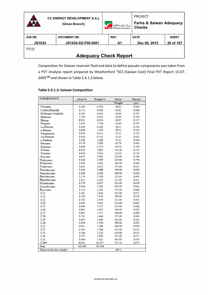
Composition for Saiwan reservoir fluid and data to define pseudo-components was taken from
a PVT Analysis report prepared by Weatherford “SE2-(Saiwan East) Final PVT Report 15-07-
2009”R4
and shown in Table 5.4.1.3 below.
Table 5.4.1.3: Saiwan Composition

7/25/2019 JS1034-XX-F06-0001. A1
http://slidepdf.com/reader/full/js1034-xx-f06-0001-a1 27/107
CC ENERGY DEVELOPMENT S.A.L
(Oman Branch)
PROJECT
Farha & Saiwan AdequacyChecks
JOB NR. DOCUMENT NR. REV. DATE SHEET
JS1034 JS1034-XX-F06-0001 A1 Dec 09, 2015 27 of 107
TITLE
Adequacy Check Report
JS1034-XX-F06-0001.A1
Composition for SHAHD ‘H’ & ‘I’ reservoir fluids and data to define pseudo-components
was taken from a PVT Analysis report prepared by SGS “Oman CCED Well SHH-1 Prelim
Report 04-July-2015”R5
and shown in Table 5.4.1.4 below.
Table 5.4.1.4: SHAHD Composition
All molecular weights used in the simulations matched those stated by the individual PVT
reports.

7/25/2019 JS1034-XX-F06-0001. A1
http://slidepdf.com/reader/full/js1034-xx-f06-0001-a1 28/107
CC ENERGY DEVELOPMENT S.A.L
(Oman Branch)
PROJECT
Farha & Saiwan AdequacyChecks
JOB NR. DOCUMENT NR. REV. DATE SHEET
JS1034 JS1034-XX-F06-0001 A1 Dec 09, 2015 28 of 107
TITLE
Adequacy Check Report
JS1034-XX-F06-0001.A1
5.4.2 Key Component Conditions
The key component (equipment) operating conditions used for the simulation are as per Table
5.4.2.1 below.
Table 5.4.2.1: Key Component Operating Conditions for Simulation
Description Temperature (OC) Pressure (Barg)
Farha Reservoir 57.16 140.9
Saiwan Reservoir 61.5 179
SHAHD Reservoir 82 90
Production Separators (Farha & Saiwan) 20 5
Heater Treaters (Farha & Saiwan) 67 4
Atmospheric Storage Tanks (Farha & Saiwan)
66.7 (actual on
P&ID 58.6)
0.98 (actual on
P&ID 0.1)
5.5 Simulation Cases & Production Profile Scenarios
5.5.1 Simulation Cases
Two cases where considered for simulation for both Farha and Saiwan Plants. The first was
winter case (20OC at inlet to Production Separators) and the second was a summer case
simulation (55
O
C at inlet to Production Separators). However, for purposes of Heat & MassBalances
A1, only the normal operating conditions were considered which correspond to the
winter case simulation models.
The adequacy checks were therefore carried out with normal operating conditions (winter
case data). The data from the summer case model was not used to carry out adequacy checks
for both Farha and Saiwan Crude Treatment Facilities. The simulation case files can be found
under reference 6 of this study document.
7/25/2019 JS1034-XX-F06-0001. A1
http://slidepdf.com/reader/full/js1034-xx-f06-0001-a1 29/107
CC ENERGY DEVELOPMENT S.A.L
(Oman Branch)
PROJECT
Farha & Saiwan Adequacy Checks
JOB NR. DOCUMENT NR. REV. DATE SHEET
JS1034 JS1034-XX-F06-0001 A1 Dec 09, 2015 29 of 107
TITLE
Adequacy Check Report
JS1034-XX-F06-0001.A1
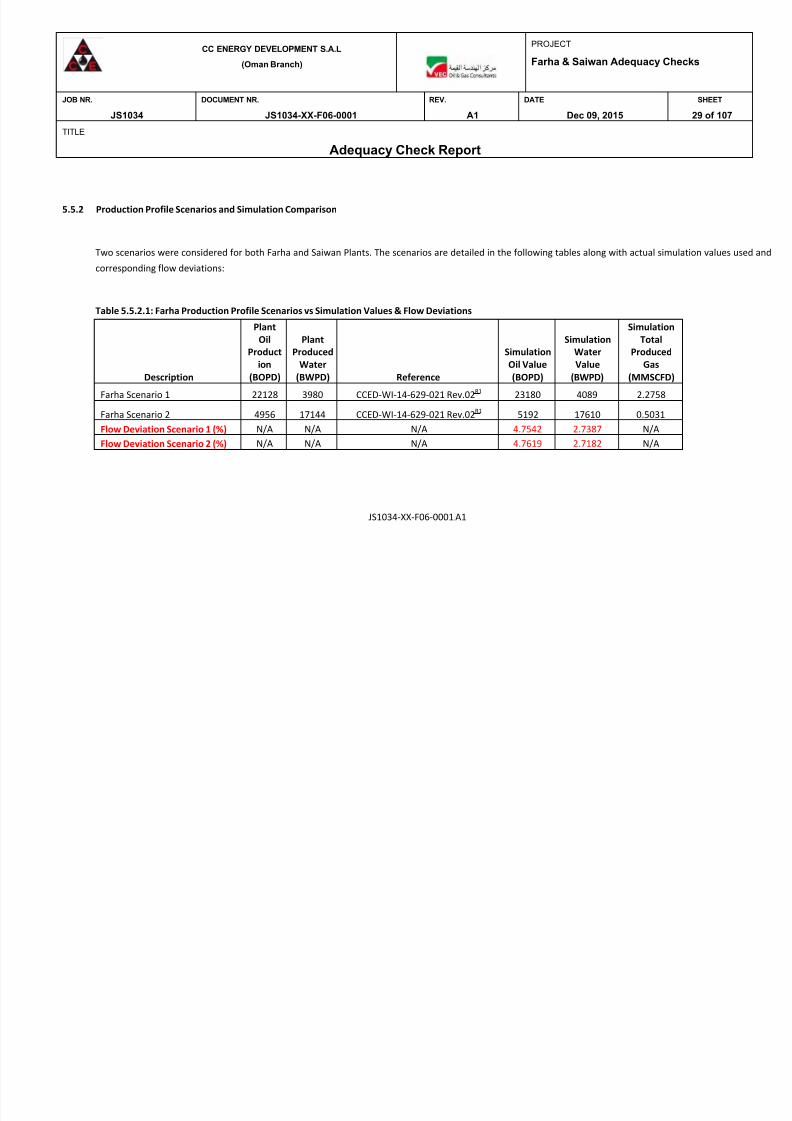
5.5.2 Production Profile Scenarios and Simulation Comparison
Two scenarios were considered for both Farha and Saiwan Plants. The scenarios are detailed in the following tables along with actual simulation values used and
corresponding flow deviations:
Table 5.5.2.1: Farha Production Profile Scenarios vs Simulation Values & Flow Deviations
Description
Plant
Oil
Product
ion
(BOPD)
Plant
Produced
Water
(BWPD) Reference
Simulation
Oil Value
(BOPD)
Simulation
Water
Value
(BWPD)
Simulation
Total
Produced
Gas
(MMSCFD)
Farha Scenario 1 22128 3980 CCED-WI-14-629-021 Rev.02R1 23180 4089 2.2758
Farha Scenario 2 4956 17144 CCED-WI-14-629-021 Rev.02R1
5192 17610 0.5031
Flow Deviation Scenario 1 (%) N/A N/A N/A 4.7542 2.7387 N/A
Flow Deviation Scenario 2 (%) N/A N/A N/A 4.7619 2.7182 N/A

7/25/2019 JS1034-XX-F06-0001. A1
http://slidepdf.com/reader/full/js1034-xx-f06-0001-a1 30/107
CC ENERGY DEVELOPMENT S.A.L
(Oman Branch)
PROJECT
Farha & Saiwan Adequacy Checks
JOB NR. DOCUMENT NR. REV. DATE SHEET
JS1034 JS1034-XX-F06-0001 A1 Dec 09, 2015 30 of 107
TITLE
Adequacy Check Report
JS1034-XX-F06-0001.A1
Table 5.5.2.2: Saiwan (Saiwan East Crude Only) Production Profile Scenarios vs Simulation Values & Flow Deviations
Description
Separator
Oil
Production
(BOPD)
Produced
Water
(BWPD) Reference
Simulation
Oil Value
(BOPD)
Simulation
Water
Value
(BWPD)
Simulation Produced
Gas (Separator +
Heater Treater)
(MMSCFD)
Saiwan Scenario 1 & 2 (Saiwan
Crude) 10000 23333
Max Separator throughput capacity of oil
based on 30 mins residence time
(Separator MRB Reference R8) - 70 %
Water Cut - CCED Instruction 10460 24020 1.1162
Flow Deviation (%) N/A N/A N/A 4.6000 2.9443 N/A
Table 5.5.2.3: Saiwan Total Produced Gas
Description Simulation Total Produced Gas (MMSCFD)Saiwan Scenario 1 2.6669
Saiwan Scenario 2 6.1581

7/25/2019 JS1034-XX-F06-0001. A1
http://slidepdf.com/reader/full/js1034-xx-f06-0001-a1 31/107
CC ENERGY DEVELOPMENT S.A.L
(Oman Branch)
PROJECT
Farha & Saiwan Adequacy Checks
JOB NR. DOCUMENT NR. REV. DATE SHEET
JS1034 JS1034-XX-F06-0001 A1 Dec 09, 2015 31 of 107
TITLE
Adequacy Check Report
JS1034-XX-F06-0001.A1
Table 5.5.2.4: Saiwan (SHAHD Crude Only) Production Profile Scenarios vs Simulation Values & Flow Deviations
Description
Train 2 Oil
Production
(BOPD)
Produced
Water
(BWPD) Reference
Simulation
Oil Value
(BOPD)
Simulation
Water
Value
(BWPD)
Simulation Produced
Gas (Separator + Heater
Treater) (MMSCFD)
Saiwan Scenario 1
(SHAHD 'H' & 'I' Crude) 2972 1161
SHAHD Production Profile - Max
Combined Values - Reference R7 2591 1214 1.2645
Saiwan Scenario 2
(SHAHD 'H' & 'I' Crude) 10000 3908
10,000 throughput as an absolute
maximum SHAHD production
figure. Cut same as scenario 1 -
28.1 % 9329 4368 4.5513
Flow Deviation
Scenario 1 (%) N/A N/A N/A -12.8197 4.5650 N/A
Flow Deviation
Scenario 2 (%) N/A N/A N/A -6.7100 11.7707 N/A
7/25/2019 JS1034-XX-F06-0001. A1
http://slidepdf.com/reader/full/js1034-xx-f06-0001-a1 32/107
CC ENERGY DEVELOPMENT S.A.L
(Oman Branch)
PROJECT
Farha & Saiwan AdequacyChecks
JOB NR. DOCUMENT NR. REV. DATE SHEET
JS1034 JS1034-XX-F06-0001 A1 Dec 09, 2015 32 of 107
TITLE
Adequacy Check Report
JS1034-XX-F06-0001.A1
In addition to the production values provided under Section 5.5.2, an additional volume of
30,000 BOPD of SHAHD stabilised crude and approximately 23,000 BOPD of Farha stabilised
crude is added to the Saiwan Storage Tanks for export to Alam Station via the Saiwan – Alam
Export Pipeline. PFDsA6&A7
for Farha and Saiwan are to be referenced alongside the Heat and
Mass Balance DocumentA1
and can be found as attachments to this Study Report.
6 FARHA PROCESS EQUIPMENT
6.1 Inlet Manifold (201-XY-001B)
The Inlet Manifold (201-XY-001B) serves the main Farha Crude Treatment Facility and provides
feed input from the wells to the Production Separators (201-VS-001A/B/C).
The Production Header of the Inlet Manifold was evaluated based upon the new worst case
flow (Scenario 1) in order to check the adequacy. Based on the calculationA8
performed, it was
found that the Production Header is adequate to handle the new increased flow. The flow
regime determined is slug and bubble flow. No details were available regarding the length of
the Production Header so a check was made simply using the nominal diameter of Pipe.
6.2 Production Separators (201-VS-001A/B/C)
All Farha Production Separators process the same well fluids and are operated in parallel to
each other and therefore see the same flow rates with regards to inputs to and outputs from
the Separator.
An operating envelope was developed based upon Scenario 1 which is the worst case with
respect to highest flow rates for both gas and liquid. It was found that the limiting factors are
the gas and liquid nozzle capacities. The upper limit for the gas nozzle capacity is 89500 Sm3/d
and that for the liquid nozzle capacity is 1576 m3/d.

7/25/2019 JS1034-XX-F06-0001. A1
http://slidepdf.com/reader/full/js1034-xx-f06-0001-a1 33/107
CC ENERGY DEVELOPMENT S.A.L
(Oman Branch)
PROJECT
Farha & Saiwan AdequacyChecks
JOB NR. DOCUMENT NR. REV. DATE SHEET
JS1034 JS1034-XX-F06-0001 A1 Dec 09, 2015 33 of 107
TITLE
Adequacy Check Report
JS1034-XX-F06-0001.A1
Based on scenario 1, the Production Separators would be operating within the operating
envelope at a gas capacity of 744.72 Sm3/d and a liquid capacity of 1460.136 m
3/d. BS&W data
was not available and therefore the water cut percentage was used to signify BS&W % vol/vol.
The operating envelope chartA10
is attached to this Study Report. The chart contains a black
dot, showing the operating flows of the Production Separator after the addition of 2 identical
separation trains. It is therefore concluded that the Production Separators are adequate for
operation under both scenarios 1 & 2.
The operating envelope was developed in line with API Spec 12J guidelinesR10
and references
are also made to DEPs. The Farha Production Separator MRBR9
was also referenced alongside
P&IDs in order to obtain the required information for input to the operating envelope sheet.
6.3 Dehydration (Heater Treaters 201-FY-001A/B/C)
All Farha Heater Treaters process the same crude output from their respective upstream
Production Separators which operate in parallel to each other.
An operating envelopeA11
was developed based upon Scenario 1 which is the worst case with
respect to highest crude oil flow rates. The operating envelope lies between the inlet nozzle
capacity, gas nozzle capacity and liquid nozzle capacity. The Farha Heater Treater GAR11
was
used to obtain information for input to the operating envelope sheet.
Currently, based on scenario 1, the Heater Treater is operating with a liquid flow rate of
1247.52 m3/day and a gas flow rate of 486.24 m
3/day. These values are within the established
operating envelope limits and we can therefore conclude that all three Heater Treater units
are adequate for service with respect to the increased production. The operating envelope
chartA11
is included as an attachment to this Study Report.
7/25/2019 JS1034-XX-F06-0001. A1
http://slidepdf.com/reader/full/js1034-xx-f06-0001-a1 34/107
CC ENERGY DEVELOPMENT S.A.L
(Oman Branch)
PROJECT
Farha & Saiwan AdequacyChecks
JOB NR. DOCUMENT NR. REV. DATE SHEET
JS1034 JS1034-XX-F06-0001 A1 Dec 09, 2015 34 of 107
TITLE
Adequacy Check Report
JS1034-XX-F06-0001.A1
6.4 Oil Storage
Farha Plant has two Crude Oil Storage (Tanks 221-TA-001A/B) which are identical in
dimensions and therefore storage capacity. Each has a capacity of 3843 m3 and based upon
the Process Design BasisR2
, each must have a capacity corresponding to 48 hrs of production.
The idea is that one tank will be in service whilst the other is acting as a standby. The gas
flashing off at the Storage Tanks is sent directly to the AP Flare under pressure control and so
we will only be considering the volume of crude oil production. Based on Scenario 1 which is
the maximum production case, the production rate is 146.6 m3/hr. This equates to 7036.8 m
3
of crude oil production over a 48 hour period.
Based upon the sizing and sparing philosophy as per the Process Design BasisR2
, the Crude Oil
Storage Tanks are inadequate. This effectively means that neither of the two tanks can act as a
standby. However, if the philosophy is changed to a 24 hour production limit per Tank, then
both tanks are adequate for 24 hrs of production and either one can be used as a standby tank
whilst the other is in operation.
It is recommended to increase the number of Storage Tanks during the detail design stage of
Phase 2B expansion project.
The Off –Spec Storage Tank is also inadequate when considering capacity to be equal to 24hrs
of normal crude production based on scenario 1. The capacity for the Off –Spec Storage Tank
is 2830 m3, whereas the required capacity based on 24 hrs crude oil production as per the
Process Design BasisR2 is 3518.4 m3.
6.5 Oil Export (Export Pumps & Pipeline)
6.5.1 10” Pipeline Farha to Saiwan
The 10” Export Pipeline from Farha to Saiwan was found to be adequate for the higher flow
scenario 1. PipesimA29
was used to simulate the Export Pipeline and the elevations used were

7/25/2019 JS1034-XX-F06-0001. A1
http://slidepdf.com/reader/full/js1034-xx-f06-0001-a1 35/107
CC ENERGY DEVELOPMENT S.A.L
(Oman Branch)
PROJECT
Farha & Saiwan AdequacyChecks
JOB NR. DOCUMENT NR. REV. DATE SHEET
JS1034 JS1034-XX-F06-0001 A1 Dec 09, 2015 35 of 107
TITLE
Adequacy Check Report
JS1034-XX-F06-0001.A1
as per the elevation file provided by CCEDR12
. Pressure drops and velocities were satisfactory
and acceptable. For detailed results, please make reference to the PipeSim simulation fileR14
.
6.5.2 Oil Transfer Booster Pumps (221-PA-002A/B/C) & Oil Transfer Pumps (221-PA-001A/B/C)
The volume of crude oil to be exported from Farha to Saiwan (Scenario 1) is the equivalent of
153.6 m3/hr. Each of the Oil Transfer Booster Pumps and Oil Transfer Pumps are already rated
for 73 m3/hr. The pumps will be used based upon a 2 working and 1 standby philosophy.
This means that each pump should be able to pump 76.8m3/hr of crude to Saiwan Storage
Tanks. The new pumping rate is not that much more than the existing rated flow and after
plotting on the original vendor supplied pump curves, it emerged that the pumps were
adequate with little or no difference in specifications. The marked pump curvesA12
are
attached to this Study Report.
7 SAIWAN PROCESS EQUIPMENT
7.1 Inlet Manifold
The Inlet Manifold (200-XY-001A) serves the Saiwan Crude Treatment Facility and provides
feed input from Saiwan East wells to the Production Separators (200-VS-001A/B).
The Production Header of the Inlet Manifold was evaluated based upon the new worst case
flow (10,000 BOPD throughput of Saiwan East Crude) in order to check the adequacy. Based
on the calculationA9
performed, it was found that the Production Header is adequate to handle
the new increased flow. The flow regime determined is slug flow. No details were available
regarding the length of the Production Header so a check was made simply using the nominal
diameter of Pipe.
A second Inlet Manifold (200-XY-001B) will be required to provide SHAHD ‘H’ & ‘I’ produced
well fluids to Train 2 of Saiwan Crude Treatment Plant. This would need to be sized during
detailed design of Phase 2B of the expansion project.

7/25/2019 JS1034-XX-F06-0001. A1
http://slidepdf.com/reader/full/js1034-xx-f06-0001-a1 36/107
CC ENERGY DEVELOPMENT S.A.L
(Oman Branch)
PROJECT
Farha & Saiwan AdequacyChecks
JOB NR. DOCUMENT NR. REV. DATE SHEET
JS1034 JS1034-XX-F06-0001 A1 Dec 09, 2015 36 of 107
TITLE
Adequacy Check Report
JS1034-XX-F06-0001.A1
7.2 Production Separators (200-VS-001A/B)
Production Separators at Saiwan, process two types of well-produced fluids. Saiwan East wells
are processed in Train 1 and SHAHD ‘H’ & ‘I’ are processed in Train 2. The higher flow rate case
for Saiwan is Scenario 2.
An operating envelopeA13
was developed based upon Scenario 2 which is the worst case with
respect to highest flow rates for both gas and liquid. It was found that the limiting factors are
the gas and liquid nozzle capacities. The upper limit for the gas nozzle capacity is 98400 Sm3/d
and that for the liquid nozzle capacity is 1576 m3/d.
Based on scenario 2, the Production Separator (200-VS-001A) with Saiwan produced well
fluids is to operate outside of the established operating envelope at a gas capacity of 22924.8
Sm3/d and a liquid capacity of 5385.36 m
3/d. BS&W data was not available and therefore the
water cut percentage of 70 % was used to signify BS&W % vol/vol.
The operating envelope chartA13
is attached to this Study Report and contains a black dot,
showing the operating flows of the Production Separator after the addition of an identical
separation train. The additional Separator is to be used to process SHAHD produced well
fluids. It is concluded that the Production Separator (200-VS-001A) is inadequate for operation
under both scenarios 1 & 2 for Saiwan East Wells.
The operating envelope was developed in line with API Spec 12J guidelines R10 and references
are also made to DEPs. The Saiwan Production Separator MRBR8
was also referenced alongside
P&IDs in order to obtain the required information for input to the operating envelope sheet.
The second Production Separator (200-VS-001B) was evaluated using SHAHD produced well
fluids and a similar operating envelopeA14
was prepared. Based on scenario 2, it was found
that the Production Separator (200-VS-001B) is inadequate to handle processing of SHAHD
produced well fluids.
7/25/2019 JS1034-XX-F06-0001. A1
http://slidepdf.com/reader/full/js1034-xx-f06-0001-a1 37/107
CC ENERGY DEVELOPMENT S.A.L
(Oman Branch)
PROJECT
Farha & Saiwan AdequacyChecks
JOB NR. DOCUMENT NR. REV. DATE SHEET
JS1034 JS1034-XX-F06-0001 A1 Dec 09, 2015 37 of 107
TITLE
Adequacy Check Report
JS1034-XX-F06-0001.A1
7.3 Dehydration (Heater Treaters 200-FY-001A/B)
Operating envelopes were developed for both the Saiwan Heater Treater units and it was
concluded that they are adequate to handle both Saiwan and SHAHD well produced fluids.
Under scenario 2, both are operating within the limits of the defined operating envelopeA15 &
A16. The Saiwan Heater Treater GAR14 was used alongside Unisim to obtain information for
input to the operating envelope sheet.
7.4 Oil Storage
Saiwan Plant has two Crude Oil Storage (Tanks 220-TA-001A/B) which are identical in
dimensions and therefore storage capacity. Each has a capacity of 5420 m3 and based upon
the Process Design BasisR2
, each must have a capacity corresponding to 48 hrs of Saiwan Plant
production only (excluding Farha). The Saiwan Plant maximum production is 1667.04 m3/d
which equates to 3334.08 m3
over a period of 48 hrs. The idea is that one tank will be in
service whilst the other is acting as a standby. The gas flashing off at the Storage Tanks is sent
directly to the AP Flare under pressure control.
Based upon the sizing and sparing philosophy as per the Process Design BasisR2
, the Crude Oil
Storage Tanks are adequate.
It is noted however that we have a continuous supply of stabilised Farha and SHAHD crude
being added to the Saiwan Storage Tanks on a daily basis. At maximum flow, this amounts to
10383.84 m3/day of crude heading to Saiwan Storage Tanks. Based upon this figure, the
storage tanks would need to be operated in parallel as opposed to one being a standby tank
and we would be inclined to say that the tanks are inadequate with respect to the
standby/sparing philosophy as per the Process Design BasisR2
.
It is recommended to increase the number of Storage Tanks during the detail design stage of
Phase 2B expansion project.
7/25/2019 JS1034-XX-F06-0001. A1
http://slidepdf.com/reader/full/js1034-xx-f06-0001-a1 38/107
CC ENERGY DEVELOPMENT S.A.L
(Oman Branch)
PROJECT
Farha & Saiwan AdequacyChecks
JOB NR. DOCUMENT NR. REV. DATE SHEET
JS1034 JS1034-XX-F06-0001 A1 Dec 09, 2015 38 of 107
TITLE
Adequacy Check Report
JS1034-XX-F06-0001.A1
The Off –Spec Storage Tank is however adequate when considering capacity to be equal to
24hrs of normal crude production based on scenario 2. The capacity for the Off –Spec Storage
Tank is 2830 m3, whereas the required capacity based on 24 hrs crude oil production as per
the Process Design BasisR2
is 1667.04 m3.
7.5 Oil Export (Export Pumps & Pipeline)
7.5.1 16” Pipeline Saiwan to Alam
The 16” Export Pipeline from Saiwan to Alam is found to be adequate for the highest peak
flow from Saiwan. PipesimR16
was used to simulate the Export Pipeline and the elevations used
were as per the elevation file provided by CCEDR13
. Pressure drops and velocities were
satisfactory and acceptable. For detailed results, please make reference to the PipeSim
simulation fileA30
.
7.5.2 Oil Transfer Booster Pumps (220-PA-002A/B/C) & Oil Transfer Pumps (220-PA-
001A/B/C)
The volume of crude oil to be exported from Saiwan to Alam (Scenario 2) is the equivalent of
493.4 m3/hr. Each of the Oil Transfer Booster Pumps and Oil Transfer Pumps are already rated
for 116 m3/hr.
Referencing the vendor supplied pump curves it was observed that for the Booster Pumps,
one can operate them on a 2 working and 1 standby philosophy but it means one is at the end
of the performance curves and the pumps are likely to be inefficient. Ideally one would want
to carry out this operation with 3 working pumps at a rate of 164.4m3/hr per pump. One
would require at least 1 spare for this operation.
For the Oil Transfer Pumps, the situation is worse whereby a 3 working pump (164.4m3/hr per
pump) operation leaves you at the end of the performance curves and ideally one would
require 4 working pumps to attain the required export pumping rate of 123.35 m3/hr per
pump. One would need at least 2 spares for this operation.
7/25/2019 JS1034-XX-F06-0001. A1
http://slidepdf.com/reader/full/js1034-xx-f06-0001-a1 39/107
CC ENERGY DEVELOPMENT S.A.L
(Oman Branch)
PROJECT
Farha & Saiwan AdequacyChecks
JOB NR. DOCUMENT NR. REV. DATE SHEET
JS1034 JS1034-XX-F06-0001 A1 Dec 09, 2015 39 of 107
TITLE
Adequacy Check Report
JS1034-XX-F06-0001.A1
The marked pump curvesA17
are attached to this Study Report.
8 FARHA UTILITIES (Excluding Electrical)
8.1 Instrument Air System
The total instrument and utility air consumption for Farha Plant is calculated to be 71.56
Nm3/hr
A2. This consumption figure takes into account all instrument air requirements for Plant
Control Valves and Shutdown Valves and also Utility Air Consumption for Heater Treater
Burners for the three trains. It also takes into account an additional 10 % for purposes of jet
cleaning during maintenance of plant equipment.
The current capacity of the Instrument Air Package is 70 Nm3/hr and is therefore inadequate.
It is recommended that another Instrument Air Package be employed in order to satisfy the
instrument air requirements and ensuring plant safety and shutdown is not compromised.
8.2 Chemical Dosing Packages
The Demulsifier Package (121-XX-001) is found to be inadequate. Considering the
incorporation of two more separation trains at Farha, the minimum delivery required for the
demulsifying agent is 18 litres per hour. The current dosing pumps are rated at a maximum
flow rate of 15 litres per hour. An additional demulsifier package will be required at Farha
Plant.
The Corrosion Inhibitor Package (121-XX-002) is found to be adequate and no additional
package is required at the Farha Plant considering the incorporation of two additional
separation trains.
For 3 Separation Trains, the total corrosion inhibitor dosing rate is 0.006m3/hr. This equates to
1.008 m3
of corrosion inhibitor requirement for 7 days. The Storage Tank is thereforeadequate based on 7 days storage as per the Process Design Basis
R2.

7/25/2019 JS1034-XX-F06-0001. A1
http://slidepdf.com/reader/full/js1034-xx-f06-0001-a1 40/107
CC ENERGY DEVELOPMENT S.A.L
(Oman Branch)
PROJECT
Farha & Saiwan AdequacyChecks
JOB NR. DOCUMENT NR. REV. DATE SHEET
JS1034 JS1034-XX-F06-0001 A1 Dec 09, 2015 40 of 107
TITLE
Adequacy Check Report
JS1034-XX-F06-0001.A1
The total demulsifier dosing rate is 0.018m3/hr. This equates to 3.024 m
3of demulsifier
requirement for 7 days. The Demulsifier Storage Tank is therefore inadequate based on 7 days
storage as per the Process Design BasisR2
.
8.3 Diesel Storage System
The Diesel Storage System for Farha is found to be adequate considering the incorporation of
the additional two separation trains except for the Diesel Storage Tank whose capacity is 295
m3 and the required capacity is calculated to be 299.154 m
3. The philosophy followed for the
adequacy check is as per the Process Design BasisR2
. Table 8.3.1 overleaf shows the calculated
values and corresponding checks.

7/25/2019 JS1034-XX-F06-0001. A1
http://slidepdf.com/reader/full/js1034-xx-f06-0001-a1 41/107
CC ENERGY DEVELOPMENT S.A.L
(Oman Branch)
PROJECT
Farha & Saiwan AdequacyChecks
JOB NR. DOCUMENT NR. REV. DATE SHEET
JS1034 JS1034-XX-F06-0001 A1 Dec 09, 2015 41 of 107
TITLE
Adequacy Check Report
JS1034-XX-F06-0001.A1
Table 8.3.1: Farha Diesel Storage System Evaluation
Diesel Storage - Farha
Description Rate Unit New Requirements Units Remarks
Diesel Unloading
Pumps (431-PA-
001A/B) 30 m3/hr N/A N/A Adequate
Diesel Transferpumps (431-PA-
002A/B) 10 m3/hr 0.8252 m
3/hr
Adequate Excludingintermediate for Fire
System
Diesel supply pumps
to HT (201-PD-
001A/B) 0.212 m3/hr 0.1652 m
3/hr Adequate
Diesel Storage Tank
Capacity (431-TA-
001) 295 m3 299.154 m
3 Inadequate
Heater Treater
Diesel Day Tank
(201-TA-001) 4 m3 3.9648 m
3
Adequate 24 Hours
Supply
DG SETS Diesel Day
Tank (431-TA-002) 18 m3 15.84 m
3
Adequate 24 Hours
Supply
Diesel Consumption
1. DG Sets 0.66 m3/hr N/A N/A
Based on 3 working +
0 Standby
2. Heater Treater
Consumption (3
trains) 0.1652 m3/hr N/A N/A N/A
3. Fire Water System 2.082 m3 N/A N/A Intermediate
Based on 15 daysconsumption size
required for Diesel
Storage Tank 299.154 m3 N/A N/A N/A

7/25/2019 JS1034-XX-F06-0001. A1
http://slidepdf.com/reader/full/js1034-xx-f06-0001-a1 42/107
CC ENERGY DEVELOPMENT S.A.L
(Oman Branch)
PROJECT
Farha & Saiwan AdequacyChecks
JOB NR. DOCUMENT NR. REV. DATE SHEET
JS1034 JS1034-XX-F06-0001 A1 Dec 09, 2015 42 of 107
TITLE
Adequacy Check Report
JS1034-XX-F06-0001.A1
8.4 Flaring System
Following are the assumptions used for the LP Flare study:
The LP Flare modelA28
was configured as per the overall plot planR16
and collection
network using Aspen flare system analyser version 2007.3.
The isometrics for the piping length and fittings inside the Separator and Heater
Treater skid limits were not available at the time of the adequacy check and were
assumed as 3m for tail pipe length and 10m for 4” subheader length.
Maximum allowable back pressure for relief valves fitted with bellows was limited to
30 % of the set pressure and that for conventional relief valves was limited to 10 % of
the set pressure.
Mach number was limited to 0.5 for sub-headers and header, whereas for tail pipes it
was limited to 0.7.
System back pressure (or superimposed back pressure) was maintained at 1.5 bara.
Tail pipes were sized for rated flow for each scenario.
Sizing method for vapor was selected as API 1976 and for two-phase flow, sizing
method of API 2000 was adopted for the LP Flare model.
Maximum size of the fire circle encountered for simultaneous fire relief per scenario
was considered as an area of 232 m2 equal to 17.18 m diameter as per API 521
Addendum, May 2008.
Flare Capacity and Backpressure Assessment Scenarios
The capacity and backpressure assessment for the LP Flare Header, Sub-Header and tailpipeswas carried out based on various relief contingencies using Aspen Flarenet version 2007.3.

7/25/2019 JS1034-XX-F06-0001. A1
http://slidepdf.com/reader/full/js1034-xx-f06-0001-a1 43/107
CC ENERGY DEVELOPMENT S.A.L
(Oman Branch)
PROJECT
Farha & Saiwan AdequacyChecks
JOB NR. DOCUMENT NR. REV. DATE SHEET
JS1034 JS1034-XX-F06-0001 A1 Dec 09, 2015 43 of 107
TITLE
Adequacy Check Report
JS1034-XX-F06-0001.A1
The maximum size of the external fire zone encountered was calculated and valves relieving
simultaneously to the LP Flare were grouped according to the identified fire zone.
Capacity and backpressure assessment for the LP Flare was based upon the following three
scenarios described below:-
Fire Zone 1 & Scenario 1
201-PSV-103A/104A (Production Separator 1)
201-PSV-201A/201B (Heater Treater 1)
421-PV-280 (normal relief from Fuel Gas Control Valve)
Fire Zone 2 & Scenario 2
201-PSV-103B/104B (Production Separator 2)
201-PSV-202A/202B (Heater Treater 2)
421-PV-280 (normal relief from Fuel Gas Control Valve)
Fire Zone 3 & Scenario 3
201-PSV-103C/104C (Production Separator 3)
201-PSV-203A/203B (Heater Treater 2)
421-PV-280 (normal relief from Fuel Gas Control Valve)
The scenarios consider relief via individual or combination of relief valves depending on the
number of equipment falling into the maximum area of the determined fire zone. Three fire
zones were identified.

7/25/2019 JS1034-XX-F06-0001. A1
http://slidepdf.com/reader/full/js1034-xx-f06-0001-a1 44/107
CC ENERGY DEVELOPMENT S.A.L
(Oman Branch)
PROJECT
Farha & Saiwan AdequacyChecks
JOB NR. DOCUMENT NR. REV. DATE SHEET
JS1034 JS1034-XX-F06-0001 A1 Dec 09, 2015 44 of 107
TITLE
Adequacy Check Report
JS1034-XX-F06-0001.A1
The outcome of these scenarios was checked against the existing flare capacity, the allowable
velocity limit (Mach No) & allowable backpressure limit in the event of simultaneous relief
from RVs to the LP Flare System.
The existing flare capacity of Farha is 25,500 kg/h as per the existing P&ID JS1006-F-F02-0700-
001 Rev AB.
The Flare System for Farha is found to be adequate except for the LP Flare Knockout Drum
which is inadequate based on momentum criteria at the inlet nozzle. The results can be found
in the summary tablesA24
. All vessel Relief Valves are adequate for blocked outlet, except for
the Heater Treater Relief Valves which are inadequate for the external fire case scenario.
The AP Flare capacity is 9140 Kg/hr and is adequate for the maximum relief load to AP Flare
from Crude Oil Storage Tanks for Farha Scenario 1 of 4092 Kg/hr.
8.5 Nitrogen
The Nitrogen System is hugely inadequate with respect to API2000R8
. Considering the Storage
Tank 221-TA-001A, a calculationA4
was performed based upon two working and 1 standby Oil
Transfer Booster Pumps (221-PA-002A/B/C) at maximum pumping rates. A summary of the
results is shown in the table below.
Vessel
In-breathing (Nm³/h) Total In-breathing(Nm
3 /h)
Out-breathing (Nm³/h) Totaloutbreathing
(Nm3 /h)Liquid
MovementThermal
EffectLiquid Movement Thermal
Effect
Storage Tank(221-TA-001A) 132.2 33.4 165.6 155.2 8.57 163.8
The in-breathing requirement for just one of the two storage tanks amounts to 3974.4 Nm3 of
nitrogen per day. Based upon the philosophy as depicted by the Process Design BasisR2
, the
Nitrogen System is to be sized for a back-up of 3 days. This amounts to 11923.2 Nm3 of
nitrogen required for blanketing of just one Storage Tank alone during normal operation.

7/25/2019 JS1034-XX-F06-0001. A1
http://slidepdf.com/reader/full/js1034-xx-f06-0001-a1 45/107
CC ENERGY DEVELOPMENT S.A.L
(Oman Branch)
PROJECT
Farha & Saiwan AdequacyChecks
JOB NR. DOCUMENT NR. REV. DATE SHEET
JS1034 JS1034-XX-F06-0001 A1 Dec 09, 2015 45 of 107
TITLE
Adequacy Check Report
JS1034-XX-F06-0001.A1
There is a second Storage Tank (221-TA-001B) which is used as a standby and also the Off-Spec
Tank (221-TA-002) which are to be considered whilst calculating the required nitrogen for
blanketing purposes but considering the current Nitrogen System capacity is 1920 Nm3, we
already know that this system is inadequate for purpose and at best can only supply
blanketing gas to one Storage Tank under normal operation for 11.5 hours.
Further to the above, it is very unlikely that the current Crude Storage Tanks fit the sizing
philosophy for Storage Tanks as per the Process Design BasisR2
i.e. one tank to be sized for 48
hrs of normal production. This would mean further Storage Tanks and therefore a much
greater requirement of nitrogen than what is foreseen above. The Nitrogen System should be
re-sized during the detailed design stage of Phase 2B of the expansion project.
8.6 Utility Water
The utility water adequacy check was carried out based upon a daily utility water consumption
value of 250 litres per day (0.25 m3/day) per user based upon the Process Design Basis
R2. This
amounts to 3.75 m3 consumption of utility water per user for a minimum period of 15 days
based upon guidelines as set by the Process Design BasisR2
.
Based upon the capacity of the Water Storage Tank 521-TA-001 (160 m3), the storage is
enough for 42 users per day for a period of 15 days. The Utility Water Pumps (521-PA-001A/B)
are more than adequate with a peak flow rate of 8 m
3
/hr. As per the Process Design Basis
R2
,this value is stated to be 5 m
3/hr as a maximum.
The Utility Water System is therefore adequate, as it fulfils all criteria as set out in the Process
Design BasisR2
.
8.7 Closed Drain System
As per the Process Design BasisR2
, the Closed Drain Drum must be sized for the liquid hold up
of one process vessel other than the Crude Oil Storage Tanks. The process vessel with the

7/25/2019 JS1034-XX-F06-0001. A1
http://slidepdf.com/reader/full/js1034-xx-f06-0001-a1 46/107
CC ENERGY DEVELOPMENT S.A.L
(Oman Branch)
PROJECT
Farha & Saiwan AdequacyChecks
JOB NR. DOCUMENT NR. REV. DATE SHEET
JS1034 JS1034-XX-F06-0001 A1 Dec 09, 2015 46 of 107
TITLE
Adequacy Check Report
JS1034-XX-F06-0001.A1
highest volume of liquid hold up is likely to be the Production Separator. Based upon the High-
High Level of the Production Separator (201-VS-001A), the volume of liquid held up in the
Separator equates to 13.8474 m3. The Closed Drain Drum (551-VA-001) has a capacity of 18.3
m3 and is therefore adequately sized.
Based upon the criteria set for the Closed Drain Pumps (551-PH-001A/B) as per the Process
Design BasisR2, the pump must be able to pump 0.942m3 of liquid from the Closed Drain Drum
within 30 minutes. With a rated flow of 10 m3/hr, the pump is more than adequate to handle
the required pump out criteria for the contained liquid. The volume of liquid held up was
calculated based upon the difference between high liquid level and low liquid level of the
Closed Drain Drum (400mm).
9 SAIWAN UTILITIES (Excluding Electrical)
9.1 Instrument Air System
The total instrument and utility air consumption for Saiwan Plant is calculated to be 59.39
Nm3/hr
A3. This consumption figure takes into account all instrument air requirements for Plant
Control Valves and Shutdown Valves and also Utility Air Consumption for Heater Treater
Burners for the two trains. It also takes into account an additional 10 % for purposes of jet
cleaning during maintenance of plant equipment.
The current capacity of the Instrument Air Package is 70 Nm3/hr and is therefore adequate.
9.2 Chemical Dosing Packages
The Demulsifier Package (120-XX-001) and the Corrosion Inhibitor Package (120-XX-002) are
found to be adequate and no additional packages are required at the Saiwan Plant considering
the incorporation of two additional separation trains.
7/25/2019 JS1034-XX-F06-0001. A1
http://slidepdf.com/reader/full/js1034-xx-f06-0001-a1 47/107
CC ENERGY DEVELOPMENT S.A.L
(Oman Branch)
PROJECT
Farha & Saiwan AdequacyChecks
JOB NR. DOCUMENT NR. REV. DATE SHEET
JS1034 JS1034-XX-F06-0001 A1 Dec 09, 2015 47 of 107
TITLE
Adequacy Check Report
JS1034-XX-F06-0001.A1
For 2 Separation Trains, the total corrosion inhibitor dosing rate is 0.008m3/hr. This equates to
1.344 m3 of corrosion inhibitor requirement for 7 days. The Storage Tank is therefore
adequate based on 7 days storage as per the Process Design BasisR2
.
The total demulsifier dosing rate is 0.01m3/hr. This equates to 1.68 m
3of demulsifier
requirement for 7 days. The Demulsifier Storage Tank is therefore adequate based on 7 days
storage as per the Process Design BasisR2.
9.3 Diesel Storage System
Constituent equipment for the Saiwan Diesel Storage System are found to be adequate except
for the Heater Treater Diesel Day Tank (200-TA-001), based upon the philosophy as per the
Process Design BasisR2
. Table 9.3.1 overleaf shows the calculated values and corresponding
checks.

7/25/2019 JS1034-XX-F06-0001. A1
http://slidepdf.com/reader/full/js1034-xx-f06-0001-a1 48/107
CC ENERGY DEVELOPMENT S.A.L
(Oman Branch)
PROJECT
Farha & Saiwan AdequacyChecks
JOB NR. DOCUMENT NR. REV. DATE SHEET
JS1034 JS1034-XX-F06-0001 A1 Dec 09, 2015 48 of 107
TITLE
Adequacy Check Report
JS1034-XX-F06-0001.A1
Table 9.3.1: Saiwan Diesel Storage System Evaluation
Diesel Storage - Saiwan
Description Rate Unit New Requirements Units Remarks
Diesel Unloading
Pumps (430-PA-
001A/B) 30 m3/hr N/A N/A Adequate
Diesel Transfer
pumps (430-PA-
002A/B) 12 m3/hr 0.7701 m
3/hr
Adequate Excluding
intermediate for Fire
System
Diesel supply pumps
to HT (200-PD-
001A/B) 0.122 m3/hr 0.1101 m
3/hr Adequate
Diesel Storage Tank
Capacity (430-TA-
001) 295 m3 278.277 m
3 Adequate
Heater Treater
Diesel Day Tank
(200-TA-001) 1.65 m3 2.6424 m
3
Not Adequate - 24
Hours Supply
DG SETS Diesel Day
Tank (430-TA-002) 20.4 m3 15.84 m
3
Adequate - 24 hours
supply
Diesel Consumption
1. DG Sets 0.66 m3/hr N/A N/A
Based on 3 working +
1 Standby
2. Heater Treater
Consumption (2
trains) 0.1101 m3/hr N/A N/A N/A
3. Fire Water System 2.082 m3 N/A N/A Intermediate
Based on 15 daysconsumption size
required for Diesel
Storage Tank 278.277 m3 N/A N/A N/A
9.4 Flaring System
Following are the assumptions used for the LP Flare study:
The LP Flare modelA28
was configured as per the overall plot planR17
and collection
network using Aspen flare system analyser version 2007.3.

7/25/2019 JS1034-XX-F06-0001. A1
http://slidepdf.com/reader/full/js1034-xx-f06-0001-a1 49/107
CC ENERGY DEVELOPMENT S.A.L
(Oman Branch)
PROJECT
Farha & Saiwan AdequacyChecks
JOB NR. DOCUMENT NR. REV. DATE SHEET
JS1034 JS1034-XX-F06-0001 A1 Dec 09, 2015 49 of 107
TITLE
Adequacy Check Report
JS1034-XX-F06-0001.A1
The isometrics for the piping length and fittings inside the Separator and Heater
Treater skid limits were not available at the time of the adequacy check and were
assumed as 3m for tail pipe length and 10m for 4” subheader length.
Maximum allowable back pressure for relief valves fitted with bellows was limited to
30 % of the set pressure and that for conventional relief valves was limited to 10 % of
the set pressure.
Mach number was limited to 0.5 for sub-headers and header, whereas for tail pipes it
was limited to 0.7.
System back pressure (or superimposed back pressure) was maintained at 1.5 bara.
Tail pipes were sized for rated flow for each scenario.
Sizing method for vapor was selected as API 1976 and for two-phase flow, sizing
method of API 2000 was adopted for the LP Flare model.
Maximum size of the fire circle encountered for simultaneous fire relief per scenario
was considered as an area of 232 m2 equal to 17.18 m diameter as per API 521
Addendum, May 2008.
Flare Capacity and Backpressure Assessment Scenarios
The capacity and backpressure assessment for the LP Flare Header, Sub-Header and tailpipes
was carried out based on various relief contingencies using Aspen Flarenet version 2007.3.
The maximum size of the external fire zone encountered was calculated and valves relieving
simultaneously to the LP Flare were grouped according to the identified fire zone.
Capacity and backpressure assessment for the LP Flare was based upon the following twoscenarios described overleaf:-

7/25/2019 JS1034-XX-F06-0001. A1
http://slidepdf.com/reader/full/js1034-xx-f06-0001-a1 50/107
CC ENERGY DEVELOPMENT S.A.L
(Oman Branch)
PROJECT
Farha & Saiwan AdequacyChecks
JOB NR. DOCUMENT NR. REV. DATE SHEET
JS1034 JS1034-XX-F06-0001 A1 Dec 09, 2015 50 of 107
TITLE
Adequacy Check Report
JS1034-XX-F06-0001.A1
Fire Zone 1 & Scenario 1
200-PSV-003A/004A (Production Separator 1)
200-PSV-401A/401B (Heater Treater 1)
420-PV-401 (normal relief from Fuel Gas Control Valve)
Fire Zone 2 & Scenario 2
201-PSV-103B/104B (Production Separator 2)
201-PSV-202A/202B (Heater Treater 2)
420-PV-401 (normal relief from Fuel Gas Control Valve)
The scenarios consider relief via individual or combination of relief valves depending on thenumber of equipment falling into the maximum area of the determined fire zone. Two fire
zones were identified.
The outcome of these scenarios was checked against the existing flare capacity, the allowable
velocity limit (Mach No) & allowable backpressure limit in the event of simultaneous relief
from RVs to the LP Flare System.
The existing flare capacity of Saiwan is 59,170 kg/h as per the existing P&ID JS1006-S-F02-
0663-001 Rev AB.
The Flare System for Saiwan is found to be adequate except for the LP Flare Knockout Drum
which is inadequate based upon the inlet nozzle momentum criteria. Also, the mach number
for the tailpipe of Production Separator Train 1 which is processing Saiwan crude is too high.
The results can be found in the summary tables A25. All vessel Relief Valves are adequate for
blocked outlet, except for the 1st
Train Production Separator (Saiwan Crude) and 2nd
Train
Heater Treater (SHAHD Crude) which are inadequate for the fire case scenario.

7/25/2019 JS1034-XX-F06-0001. A1
http://slidepdf.com/reader/full/js1034-xx-f06-0001-a1 51/107
CC ENERGY DEVELOPMENT S.A.L
(Oman Branch)
PROJECT
Farha & Saiwan AdequacyChecks
JOB NR. DOCUMENT NR. REV. DATE SHEET
JS1034 JS1034-XX-F06-0001 A1 Dec 09, 2015 51 of 107
TITLE
Adequacy Check Report
JS1034-XX-F06-0001.A1
The AP Flare capacity is 4200 Kg/hr and is adequate for the maximum relief load to AP Flare
from Crude Oil Storage Tanks for Saiwan Scenario 2 of 1204 Kg/hr.
9.5 Nitrogen
The Nitrogen System is hugely inadequate with respect to API2000R8
. Considering the Storage
Tank 220-TA-001A, a calculationA5
was performed based upon two working and 1 standby Oil
Transfer Booster Pumps (220-PA-002A/B/C) at maximum pumping rates. A summary of the
results is shown in the table below.
Vessel
In-breathing (Nm³/h) Total In-breathing(Nm
3 /h)
Out-breathing (Nm³/h) Total out-breathing(Nm
3 /h)Liquid
MovementThermal
Effect
LiquidMovement
ThermalEffect
Storage Tank
220-TA-001A 210.0 42.5 252.5 246.6 11.67 258.3
The in-breathing requirement for just one of the two storage tanks amounts to 6060 Nm3
of nitrogen per day. Based upon the philosophy as depicted by the Process Design BasisR2
,
the Nitrogen System is to be sized for a back-up of 3 days. This amounts to 18180 Nm3 of
nitrogen required for blanketing of just one Storage Tank alone during normal operation.
There is a second Storage Tank (220-TA-001B) which is used as a standby and also the Off-
Spec Tank (220-TA-002) which are to be considered whilst calculating the required nitrogen
for blanketing purposes but considering the current Nitrogen System capacity is 1920 Nm3,
we already know that this system is inadequate for purpose and at best can only supply
blanketing gas to one Storage Tank under normal operation for 7.5 hours.
Further to the above, it is very unlikely that the current Crude Storage Tanks fit the sizing
philosophy for Storage Tanks as per the Process Design BasisR2
i.e. one tank to be sized for
48 hrs of normal production. This would mean further Storage Tanks and therefore a much
greater requirement of nitrogen than what is foreseen above. The Nitrogen System should
be re-sized during the detailed design stage of Phase 2B of the expansion project.

7/25/2019 JS1034-XX-F06-0001. A1
http://slidepdf.com/reader/full/js1034-xx-f06-0001-a1 52/107
CC ENERGY DEVELOPMENT S.A.L
(Oman Branch)
PROJECT
Farha & Saiwan AdequacyChecks
JOB NR. DOCUMENT NR. REV. DATE SHEET
JS1034 JS1034-XX-F06-0001 A1 Dec 09, 2015 52 of 107
TITLE
Adequacy Check Report
JS1034-XX-F06-0001.A1
9.6 Utility Water
The utility water adequacy check was carried out based upon a daily utility water consumption
value of 250 litres per day (0.25 m3/day) per user based upon the Process Design Basis
R2. This
amounts to 3.75 m3 consumption of utility water per user for a minimum period of 15 days
based upon guidelines as set by the Process Design BasisR2.
Based upon the capacity of the Water Storage Tank 521-TA-001 (601 m3), the storage is
enough for 160 users per day for a period of 15 days. The Utility Water Pumps (521-PA-
001A/B) are more than adequate with a peak flow rate of 20 m3/hr. As per the Process Design
BasisR2
, this value is stated to be 5 m3/hr as a maximum.
The Utility Water System is therefore adequate, as it fulfils all criteria as set out in the Process
Design BasisR2
.
9.7 Closed Drain
As per the Process Design BasisR2
, the Closed Drain Drum must be sized for the liquid hold up
of one process vessel other than the Crude Oil Storage Tanks. The process vessel with the
highest volume of liquid hold up is likely to be the Production Separator. Based upon the High-
High Level of the Production Separator (200-VS-001A), the volume of liquid held up in the
Separator equates to 13.8474 m3. The Closed Drain Drum (550-VA-001) has a capacity of 18.3
m3 and is therefore adequately sized.
Based upon the criteria set for the Closed Drain Pumps (550-PH-001A/B) as per the Process
Design BasisR2
, the pump must be able to pump 0.942m3 of liquid from the Closed Drain Drum
within 30 minutes. With a rated flow of 10 m3/hr, the pump is more than adequate to handle
the required pump out criteria for the contained liquid. The volume of liquid held up was
calculated based upon the difference between high liquid level and low liquid level of the
Closed Drain Drum (400mm).

7/25/2019 JS1034-XX-F06-0001. A1
http://slidepdf.com/reader/full/js1034-xx-f06-0001-a1 53/107
CC ENERGY DEVELOPMENT S.A.L
(Oman Branch)
PROJECT
Farha & Saiwan AdequacyChecks
JOB NR. DOCUMENT NR. REV. DATE SHEET
JS1034 JS1034-XX-F06-0001 A1 Dec 09, 2015 53 of 107
TITLE
Adequacy Check Report
JS1034-XX-F06-0001.A1
10 FARHA MAIN HEADERS
The Crude Oil, Produced Water & Produced Gas Headers were all found to be adequate with
respect to the increased plant production.
The plant isometrics were used to evaluate lengths and equivalent lengths for fittings were
calculated and used in the final calculation for adequacy.
For the Crude Oil and Produced Gas Headers, scenario 1 flow rate values were used for the
calculation and scenario 2 flow rate values were used for Produced Water Header calculation. For
the Flare Header, please reference Section 8.4 of this Study Report.
Calculation resultsA18,A19&A20
are attached within the appendix of this Study Report.
11 SAIWAN MAIN HEADERS
The Crude Oil, Produced Water & Produced Gas Headers were all found to be adequate with
respect to the increased plant production.
The plant isometrics were used to evaluate lengths and equivalent lengths for fittings were
calculated and used in the final calculation for adequacy.
Scenario 2 flow rate values were used for all Header calculations. For the Flare Header, please
reference Section 9.4 of this Study Report.
Calculation resultsA21,A22&A23
are attached within the appendix of this Study Report.

7/25/2019 JS1034-XX-F06-0001. A1
http://slidepdf.com/reader/full/js1034-xx-f06-0001-a1 54/107
CC ENERGY DEVELOPMENT S.A.L
(Oman Branch)
PROJECT
Farha & Saiwan AdequacyChecks
JOB NR. DOCUMENT NR. REV. DATE SHEET
JS1034 JS1034-XX-F06-0001 A1 Dec 09, 2015 54 of 107
TITLE
Adequacy Check Report
JS1034-XX-F06-0001.A1
12 FARHA & SAIWAN OVERALL PLOT PLAN (Mechanical)
The current Farha Plant operation consists of one Heater Treater and one Separator. As per the
new expansion plan there will be two new Heater Treaters and two new Separators. The spacing
adequacy check is made to include all major equipment within this plant.
Existing Plot Plan Farha.
The cloud marked portion is new space for Farha Plant.

7/25/2019 JS1034-XX-F06-0001. A1
http://slidepdf.com/reader/full/js1034-xx-f06-0001-a1 55/107
CC ENERGY DEVELOPMENT S.A.L
(Oman Branch)
PROJECT
Farha & Saiwan AdequacyChecks
JOB NR. DOCUMENT NR. REV. DATE SHEET
JS1034 JS1034-XX-F06-0001 A1 Dec 09, 2015 55 of 107
TITLE
Adequacy Check Report
JS1034-XX-F06-0001.A1
Space between Major Equipment in Fahra Area.
Equipment Equipment Distance ActualDistance as per
GAP 2.5.2Remarks
OIL STORAGE TANK 221-TA-
001A
OIL STORAGE TANK 221-TA-001B 56 Meter 30 Meter
Pump 221-PA-001A/B/C OIL STORAGE TANK 221-TA-001
A/B
43.86 Meter 30 Meter
OIL STORAGE TANK 221-TA-
001 A/B
OFF-SPEC OIL TANK 221-TA-002 107.7 Meter 30 Meter
Fire Water Tank 731-TA-
001A/B
Tank 221-TA-001A/B 61.5 Meter 30 Meter
Fire Water Tank 731-TA-001A Compressor skid 491-VN-002 37.1 Meter 30 Meter
Heater Treater 201-XX-001A Separator 201-XY-003A 17.4 Meter 15 Meter
Separator 201-XY-003A Heater treater 201-XX-001B 20 Meter 15 Meter
Heater treater 201-XX-001B Separator 201-XY-003B 20.85 Meter 15 Meter
Separator 201-XY-003B Heater treater 201-XX-001C 19.15 Meter 15 Meter
Heater Treater 201-XX-001C Separator 201-XY-003C 15 Meter 15 Meter
DIESEL STORAGE TANK 431-
TA-001
End line of all heater treater 36 Meter 30.5 Meter
DIESEL STORAGE TANK 431-
TA-001
DG SETS DIESEL DAY TANK 431-
TA-002
55.1 Meter 30.5 Meter
DG SETS DIESEL DAY TANK 431-
TA-002
DEMULSIFIER DOSING
PACKAGE 121-XX-001
86.6 Meter 30.5 Meter
Heater Treater 201-XX-001A HEATER TREATER DIESEL DAY
TANK 201-TA-001
3.6 Meter NA
One New Demulsifier Dosing Package and One Instrument Package are planned for the future
and not included in the space adequacy checks.
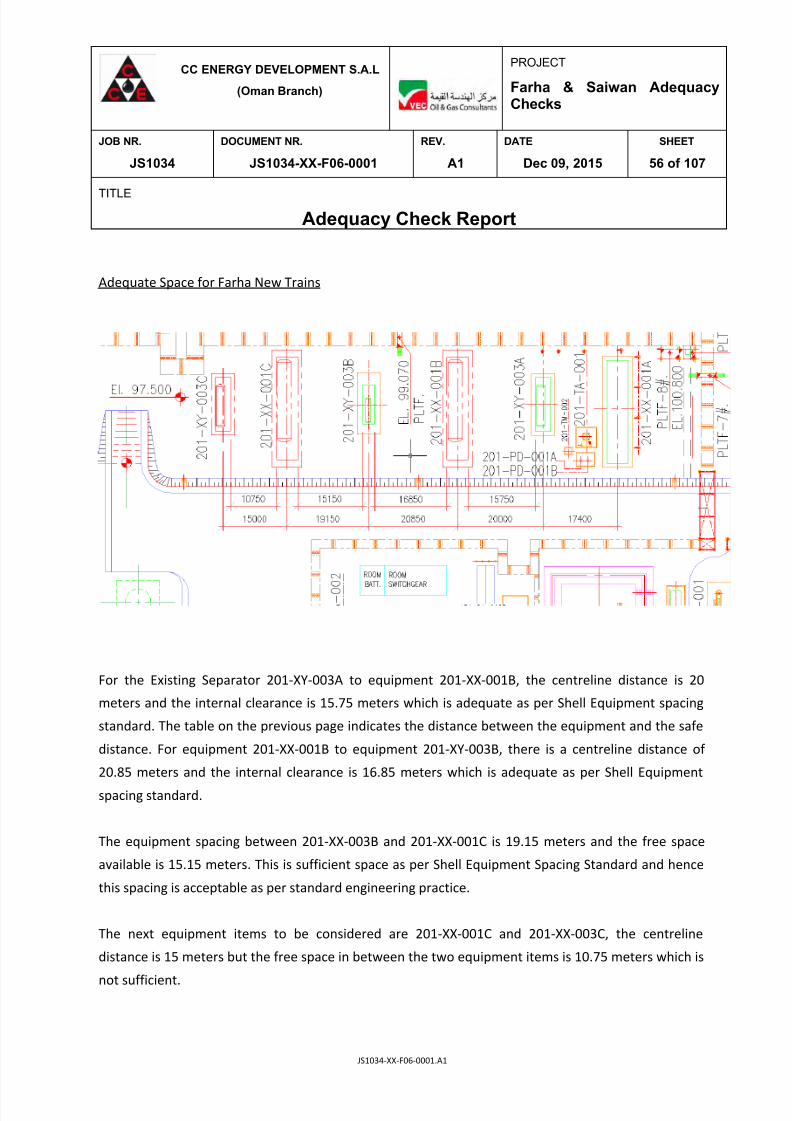
7/25/2019 JS1034-XX-F06-0001. A1
http://slidepdf.com/reader/full/js1034-xx-f06-0001-a1 56/107
CC ENERGY DEVELOPMENT S.A.L
(Oman Branch)
PROJECT
Farha & Saiwan AdequacyChecks
JOB NR. DOCUMENT NR. REV. DATE SHEET
JS1034 JS1034-XX-F06-0001 A1 Dec 09, 2015 56 of 107
TITLE
Adequacy Check Report
JS1034-XX-F06-0001.A1
Adequate Space for Farha New Trains
For the Existing Separator 201-XY-003A to equipment 201-XX-001B, the centreline distance is 20
meters and the internal clearance is 15.75 meters which is adequate as per Shell Equipment spacing
standard. The table on the previous page indicates the distance between the equipment and the safe
distance. For equipment 201-XX-001B to equipment 201-XY-003B, there is a centreline distance of
20.85 meters and the internal clearance is 16.85 meters which is adequate as per Shell Equipment
spacing standard.
The equipment spacing between 201-XX-003B and 201-XX-001C is 19.15 meters and the free space
available is 15.15 meters. This is sufficient space as per Shell Equipment Spacing Standard and hence
this spacing is acceptable as per standard engineering practice.
The next equipment items to be considered are 201-XX-001C and 201-XX-003C, the centreline
distance is 15 meters but the free space in between the two equipment items is 10.75 meters which is
not sufficient.

7/25/2019 JS1034-XX-F06-0001. A1
http://slidepdf.com/reader/full/js1034-xx-f06-0001-a1 57/107
CC ENERGY DEVELOPMENT S.A.L
(Oman Branch)
PROJECT
Farha & Saiwan AdequacyChecks
JOB NR. DOCUMENT NR. REV. DATE SHEET
JS1034 JS1034-XX-F06-0001 A1 Dec 09, 2015 57 of 107
TITLE
Adequacy Check Report
JS1034-XX-F06-0001.A1
Existing Plot Plan Saiwan
The Saiwan Plant operation currently consists of one Heater Treater and one Separator. As per the
new expansion plan, there will be one new Heater Treater and one new Separator. This adequacy
report is made considering all major equipment items within this plant.
The cloud marked portion is new space for Saiwan.

7/25/2019 JS1034-XX-F06-0001. A1
http://slidepdf.com/reader/full/js1034-xx-f06-0001-a1 58/107
CC ENERGY DEVELOPMENT S.A.L
(Oman Branch)
PROJECT
Farha & Saiwan AdequacyChecks
JOB NR. DOCUMENT NR. REV. DATE SHEET
JS1034 JS1034-XX-F06-0001 A1 Dec 09, 2015 58 of 107
TITLE
Adequacy Check Report
JS1034-XX-F06-0001.A1
Space between Major Equipment in Saiwan Area.
Equipment Equipment Distance ActualDistance as per
GAP 2.5.2Remarks
OIL STORAGE TANK 220-TA-
001A
OIL STORAGE TANK 220-TA-
001B
70.6 Meter 30 Meter
OIL STORAGE TANK 220-TA-
001A
OFF-SPEC OIL TANK 221-TA-
002
70.6 Meter 30 Meter
Heater treater 200-XX-001A Separator 200-XY-003A 16.025 Meter 15 Meter
Separator 200-XY-003A DOSING PACKAGE 120-XX-002 17.4 Meter 15 Meter
Heater treater 200-XX-001B Separator 200-XY-003B 20 Meter 15 Meter
Heater treater 200-XX-001B Fire & utility Pump house 730-
PA-003A/B
41.5 Meter 30 Meter
430-TA-001 DIESEL STORAGE
TANK
Fire & utility Pump house 730-
PA-003A/B
42.5 Meter 30 Meter
DIESEL UNLOADING PUMP
430-PA-001
430-TA-001 DIESEL STORAGE
TANK
13.5 Meter 15 Meter Not
Adequate
DIESEL UNLOADING PUMP
430-PA-001
H2S REMOVAL UNIT 330-XX-
001
31.7 Meter 30 Meter
H2S REMOVAL UNIT 330-
XX-001 DG AREA 31.9 Meter 30 Meter
Heater treater 200-XX-
001A HEATER TREATER DIESEL
DAY TANK 200-TA-001 2.65 Meter NA
Separator 200-XY-003A DEMULSIFIER DOSING
PACKAGE 120-XX-002
20.3 Meter 15 Meter

7/25/2019 JS1034-XX-F06-0001. A1
http://slidepdf.com/reader/full/js1034-xx-f06-0001-a1 59/107
CC ENERGY DEVELOPMENT S.A.L
(Oman Branch)
PROJECT
Farha & Saiwan AdequacyChecks
JOB NR. DOCUMENT NR. REV. DATE SHEET
JS1034 JS1034-XX-F06-0001 A1 Dec 09, 2015 59 of 107
TITLE
Adequacy Check Report
JS1034-XX-F06-0001.A1
Adequate Space for Saiwan New Train
In Saiwan, the existing Separator (200-VS-001A) and the Heater Treater (200-FY-001A) is exactly on
the opposite side of the new Separator (200-XY-004B) and the new Heater Treater (200-XY-003C). In
between the two trains (old and new), the space is sufficient as per shell equipment spacing standard.
In the west direction 28.9 meters is available and in the north direction it is 16 meters. Also, in
between the new Separator and Heater Treater, 16.025 meters clearance is available. However, this
does not satisfy the spacing criteria as per best engineering practices.

7/25/2019 JS1034-XX-F06-0001. A1
http://slidepdf.com/reader/full/js1034-xx-f06-0001-a1 60/107
CC ENERGY DEVELOPMENT S.A.L
(Oman Branch)
PROJECT
Farha & Saiwan AdequacyChecks
JOB NR. DOCUMENT NR. REV. DATE SHEET
JS1034 JS1034-XX-F06-0001 A1 Dec 09, 2015 60 of 107
TITLE
Adequacy Check Report
JS1034-XX-F06-0001.A1
13 FARHA AND SAIWAN - C&A ADEQUACY CHECKS
This section provides an overview of the existing Control & Safeguarding Systems at Farha South
Station & Saiwan East Station and reviews the suitability and adequacy of these systems for the
future project and also provides adequacy of existing Control Valves “Trim” calculation and
conclusions.
13.1 Control and ESD System at Farha South Station
13.1.1 Existing DCS System at Farha South Station
The Existing Farha Control System (DCS System) for Farha South Station is SIEMENS -SIMATIC
PCS 7 Process Control System design Modular S7-400 range. Existing S7-400 System contains
ET 200M I/O communication module, includes with Process Control Function and SafetyFunction.
Farha Control System has one DCS System Cabinet (CPU/IO PANEL - FARHA-IOP-001). After
checking an existing DCS Process Control System cabinet there is sufficient spares slots
available for inclusion of new cards to interface new signals.
The existing Network Cabinet is SIEMENS and Fiber-Optic Combination Shelves is SIEMENS-
SYSTIMAX 600-G2. Network Cabinet (PANEL-FARHA- NW-001) at Farha South Station Control
Room does not have sufficient spares in Rack for inclusion of new cards but it has sufficient
space for inclusion of new Network Panels.
Existing Marshalling Cabinets at Farha South Station Control Room (MARSHALLING PANEL-
FARHA-MAR-001/002/003/004) have spare space for inclusion of a new Terminal Board.

7/25/2019 JS1034-XX-F06-0001. A1
http://slidepdf.com/reader/full/js1034-xx-f06-0001-a1 61/107
CC ENERGY DEVELOPMENT S.A.L
(Oman Branch)
PROJECT
Farha & Saiwan AdequacyChecks
JOB NR. DOCUMENT NR. REV. DATE SHEET
JS1034 JS1034-XX-F06-0001 A1 Dec 09, 2015 61 of 107
TITLE
Adequacy Check Report
JS1034-XX-F06-0001.A1
13.1.2 Existing ESD System at Farha South Station
The Existing Farha ESD/FGS System for Farha South Station is SIEMENS -SIMATIC PCS 7 Process
Control System design Modular S7-400 range. Existing S7-400 System contains ET 200M I/O
communication module, includes with Process Control Function and Safety Function.
Farha ESD System has three ESD System Cabinets (IO PANEL - FARHA-IOP-002/003/004) and one
FGS system cabinet (CPU/IO PANEL-731-FG-001). After checking an existing ESD/FGS system
cabinet (CPU/IO PANEL-731-FG-001) there is sufficient spares slots available in Rack for
inclusion of new cards to interface new signals.
The table overleaf shows the Spares in DCS /ESD/FGS system cabinets at Farha South Station.

7/25/2019 JS1034-XX-F06-0001. A1
http://slidepdf.com/reader/full/js1034-xx-f06-0001-a1 62/107
CC ENERGY DEVELOPMENT S.A.L
(Oman Branch)
PROJECT
Farha & Saiwan AdequacyChecks
JOB NR. DOCUMENT NR. REV. DATE SHEET
JS1034 JS1034-XX-F06-0001 A1 Dec 09, 2015 62 of 107
TITLE
Adequacy Check Report
JS1034-XX-F06-0001.A1
S/N SYSTEM CABINET NO. SPARE “RACKS” SPARE “SLOTS”
1 CPU/IO
PANEL-731-FG-001
RACK-2 RACK-B
SLOT 7, SLOT 8, SLOT 9, SLOT
10
2 CPU/ IO
PANEL-FARHA-IOP-001
(DCS SECTION)
NO SPARE RACKS AVAILABLE RACK-C
SLOT 9, SLOT 10
RACK-H
SLOT 8, SLOT 9, SLOT 10
3 CPU/ IO
PANEL-FARHA-IOP-002
(ESD SECTION)
NO SPARE RACKS AVAILABLE RACK-F
SLOT 9, SLOT 10
RACK-G
SLOT 9, SLOT 10
4 CPU/ IO
PANEL-FARHA-IOP-003
(ESD SECTION)
NO SPARE RACKS AVAILABLE RACK-D
SLOT 7, SLOT 8, SLOT 9, SLOT
10
RACK-E
SLOT 7,SLOT 8, SLOT 9, SLOT
10
5 CPU/ IO
PANEL-FARHA-IOP-004
(ESD 1 SECTION)
RACK- 2 RACK-I
SLOT 8, SLOT 9, SLOT 10
RACK-J
SLOT 8, SLOT 9, SLOT10
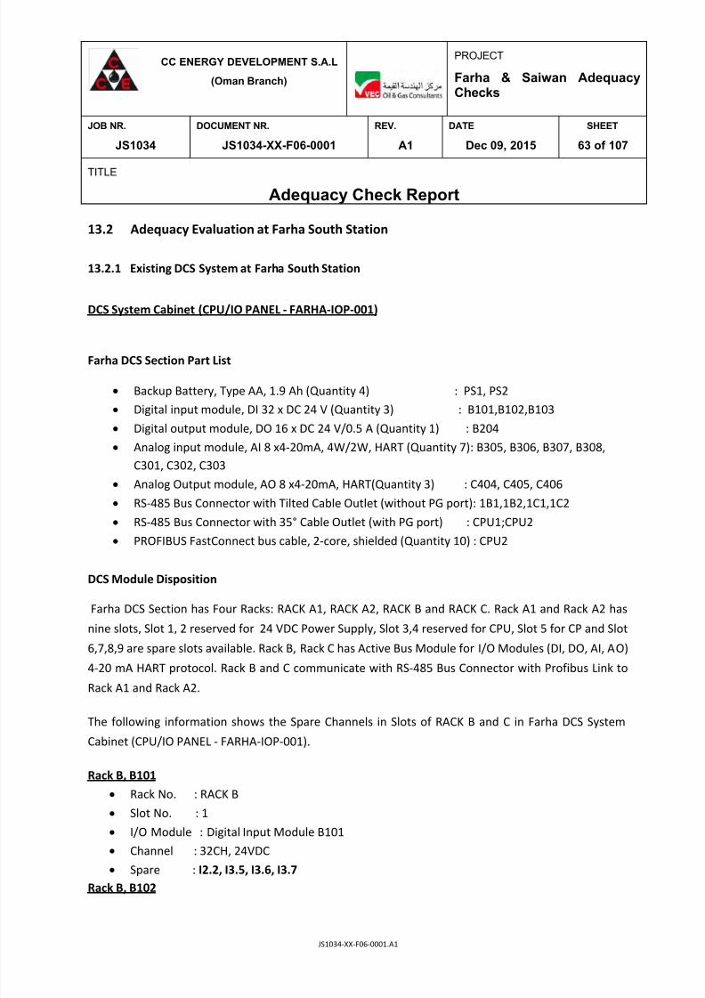
7/25/2019 JS1034-XX-F06-0001. A1
http://slidepdf.com/reader/full/js1034-xx-f06-0001-a1 63/107
CC ENERGY DEVELOPMENT S.A.L
(Oman Branch)
PROJECT
Farha & Saiwan AdequacyChecks
JOB NR. DOCUMENT NR. REV. DATE SHEET
JS1034 JS1034-XX-F06-0001 A1 Dec 09, 2015 63 of 107
TITLE
Adequacy Check Report
JS1034-XX-F06-0001.A1
13.2 Adequacy Evaluation at Farha South Station
13.2.1 Existing DCS System at Farha South Station
DCS System Cabinet (CPU/IO PANEL - FARHA-IOP-001)
Farha DCS Section Part List
Backup Battery, Type AA, 1.9 Ah (Quantity 4) : PS1, PS2
Digital input module, DI 32 x DC 24 V (Quantity 3) : B101,B102,B103
Digital output module, DO 16 x DC 24 V/0.5 A (Quantity 1) : B204
Analog input module, AI 8 x4-20mA, 4W/2W, HART (Quantity 7): B305, B306, B307, B308,
C301, C302, C303
Analog Output module, AO 8 x4-20mA, HART(Quantity 3) : C404, C405, C406
RS-485 Bus Connector with Tilted Cable Outlet (without PG port):
1B1,1B2,1C1,1C2
RS-485 Bus Connector with 35° Cable Outlet (with PG port) : CPU1;CPU2 PROFIBUS FastConnect bus cable, 2-core, shielded (Quantity 10) : CPU2
DCS Module Disposition
Farha DCS Section has Four Racks: RACK A1, RACK A2, RACK B and RACK C. Rack A1 and Rack A2 has
nine slots, Slot 1, 2 reserved for 24 VDC Power Supply, Slot 3,4 reserved for CPU, Slot 5 for CP and Slot
6,7,8,9 are spare slots available. Rack B, Rack C has Active Bus Module for I/O Modules (DI, DO, AI, AO)
4-20 mA HART protocol. Rack B and C communicate with RS-485 Bus Connector with Profibus Link to
Rack A1 and Rack A2.
The following information shows the Spare Channels in Slots of RACK B and C in Farha DCS System
Cabinet (CPU/IO PANEL - FARHA-IOP-001).
Rack B, B101
Rack No. : RACK B
Slot No. : 1
I/O Module : Digital Input Module B101
Channel : 32CH, 24VDC
Spare : I2.2, I3.5, I3.6, I3.7Rack B, B102

7/25/2019 JS1034-XX-F06-0001. A1
http://slidepdf.com/reader/full/js1034-xx-f06-0001-a1 64/107
CC ENERGY DEVELOPMENT S.A.L
(Oman Branch)
PROJECT
Farha & Saiwan AdequacyChecks
JOB NR. DOCUMENT NR. REV. DATE SHEET
JS1034 JS1034-XX-F06-0001 A1 Dec 09, 2015 64 of 107
TITLE
Adequacy Check Report
JS1034-XX-F06-0001.A1
Rack No. : RACK B
Slot No. : 2
I/O Module : Digital Input Module B102
Channel : 32CH, 24 VDC
Spare : I4.0, I4.2, I4.4, I4.6, I5.0, I5.2, I5.6, I6.0, I6.2, I6.4, I6.6, I7.0, I7.2, I7.4, I7.5, I7.6,
, I7.7
Rack B, B103
Rack No. : RACK B
Slot No. : 3
I/O Module : Digital Input Module B103
Channel : 32CH, 24 VDC
Spare : I8.0, I8.1, I8.2, I8.3, I8.5, I8.6, I8.7, I9.0, I9.2, I9.3, I9.4, I9.6, I9.7, I10.1, I10.3,
, I10.4, I10.6, I10.7 I11.0, I11.1, I11.7
Rack B, B204
Rack No. : RACK B
Slot No. : 4
I/O Module : Digital Output Module B204
Channel : 16CH, 24VDC
Spare : Q 00.3, Q00.4
Rack B, B305
Rack No. : RACK B
Slot No. : 5
I/O Module : Analog Input Module B305
Channel : 8CH
Signal : 4-20mA, HART (2 wire)
Spare : M7+ PIW526Rack B, B306
Rack No. : RACK B
Slot No. : 6
I/O Module : Analog Input Module B305
Channel : 8CH
Signal : 4-20mA, HART (2 wire)
Spare : M7+ PIW542
Rack B, B307
Rack No. : RACK B
Slot No. : 7
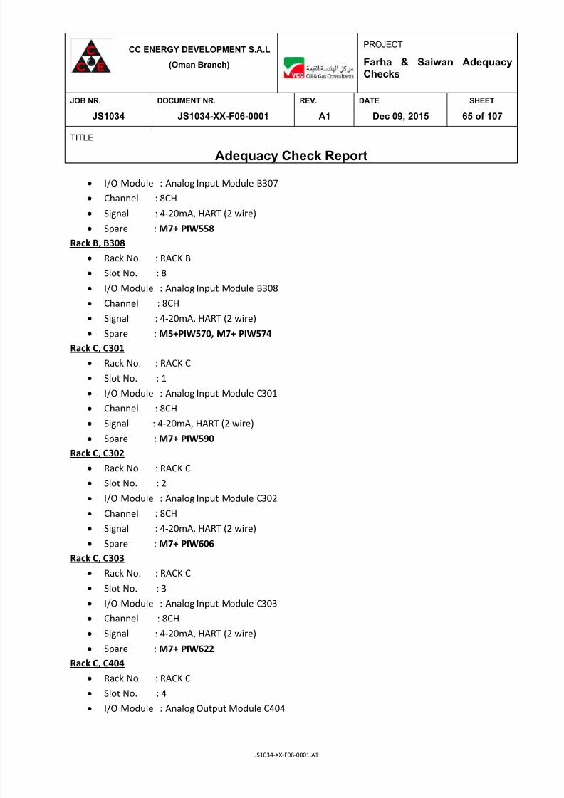
7/25/2019 JS1034-XX-F06-0001. A1
http://slidepdf.com/reader/full/js1034-xx-f06-0001-a1 65/107
CC ENERGY DEVELOPMENT S.A.L
(Oman Branch)
PROJECT
Farha & Saiwan AdequacyChecks
JOB NR. DOCUMENT NR. REV. DATE SHEET
JS1034 JS1034-XX-F06-0001 A1 Dec 09, 2015 65 of 107
TITLE
Adequacy Check Report
JS1034-XX-F06-0001.A1
I/O Module : Analog Input Module B307
Channel : 8CH
Signal : 4-20mA, HART (2 wire)
Spare : M7+ PIW558
Rack B, B308
Rack No. : RACK B
Slot No. : 8
I/O Module : Analog Input Module B308
Channel : 8CH
Signal : 4-20mA, HART (2 wire)
Spare : M5+PIW570, M7+ PIW574
Rack C, C301
Rack No. : RACK C
Slot No. : 1
I/O Module : Analog Input Module C301
Channel : 8CH
Signal : 4-20mA, HART (2 wire)
Spare : M7+ PIW590
Rack C, C302
Rack No. : RACK C
Slot No. : 2
I/O Module : Analog Input Module C302
Channel : 8CH
Signal : 4-20mA, HART (2 wire)
Spare : M7+ PIW606
Rack C, C303 Rack No. : RACK C
Slot No. : 3
I/O Module : Analog Input Module C303
Channel : 8CH
Signal : 4-20mA, HART (2 wire)
Spare : M7+ PIW622
Rack C, C404
Rack No. : RACK C
Slot No. : 4
I/O Module : Analog Output Module C404
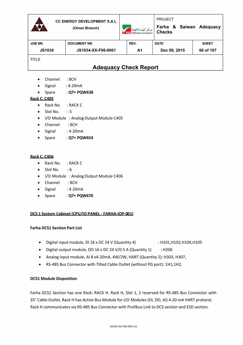
7/25/2019 JS1034-XX-F06-0001. A1
http://slidepdf.com/reader/full/js1034-xx-f06-0001-a1 66/107
CC ENERGY DEVELOPMENT S.A.L
(Oman Branch)
PROJECT
Farha & Saiwan AdequacyChecks
JOB NR. DOCUMENT NR. REV. DATE SHEET
JS1034 JS1034-XX-F06-0001 A1 Dec 09, 2015 66 of 107
TITLE
Adequacy Check Report
JS1034-XX-F06-0001.A1
Channel : 8CH
Signal : 4-20mA
Spare : Q7+ PQW638
Rack C, C405
Rack No. : RACK C
Slot No. : 5
I/O Module : Analog Output Module C405
Channel : 8CH
Signal : 4-20mA
Spare : Q7+ PQW654
Rack C, C406
Rack No. : RACK C
Slot No. : 6
I/O Module : Analog Output Module C406
Channel : 8CH
Signal : 4-20mA
Spare : Q7+ PQW670
DCS 1 System Cabinet (CPU/IO PANEL - FARHA-IOP-001)
Farha DCS1 Section Part List
Digital input module, DI 16 x DC 24 V (Quantity 4) : H101,H102,H104,H105
Digital output module, DO 16 x DC 24 V/0.5 A (Quantity 1) : H206
Analog input module, AI 8 x4-20mA, 4W/2W, HART (Quantity 2): H303, H307,
RS-485 Bus Connector with Tilted Cable Outlet (without PG port):
1H1,1H2,
DCS1 Module Disposition
Farha DCS1 Section has one Rack: RACK H. Rack H, Slot 1, 2 reserved for RS-485 Bus Connector with
35° Cable Outlet, Rack H has Active Bus Module for I/O Modules (DI, DO, AI) 4-20 mA HART protocol.
Rack H communicates via RS-485 Bus Connector with Profibus Link to DCS section and ESD section.

7/25/2019 JS1034-XX-F06-0001. A1
http://slidepdf.com/reader/full/js1034-xx-f06-0001-a1 67/107
CC ENERGY DEVELOPMENT S.A.L
(Oman Branch)
PROJECT
Farha & Saiwan AdequacyChecks
JOB NR. DOCUMENT NR. REV. DATE SHEET
JS1034 JS1034-XX-F06-0001 A1 Dec 09, 2015 67 of 107
TITLE
Adequacy Check Report
JS1034-XX-F06-0001.A1
The following information shows the Spare Channels in Slots of RACK H in Farha DCS1 System Cabinet
(CPU/IO PANEL - FARHA-IOP-001).
Rack H, H101
Rack No. : RACK H
Slot No. : 1
I/O Module : Digital Input Module H101
Channel : 16CH, 24VDC
Spare : I12.5, I13.5, I13.6, I13.7
Digital Input Module H102
Rack No. : RACK H
Slot No. : 2
I/O Module : Digital Input Module H102
Channel : 16CH, 24VDC
Spare : I15.7
Rack H, H303
Rack No. : RACK H
Slot No. : 3
I/O Module : Analog Input Module H303
Channel : 8CH
Signal : 4-20mA, HART (2 wire)
Spare : M4+ PIW776, M5+ PIW778, M6+ PIW780, M7+782
Rack H, H104
Rack No. : RACK H
Slot No. : 4
I/O Module : Digital Input Module H104
Channel : 16CH, 24VDC
Spare : I16.3, I16.4, I16.5, I16.6, I16.7, I17.2, I17.3, I17.4, I17.5, I17.6, I17.7
Rack H, H105
Rack No. : RACK H
Slot No. : 5
I/O Module : Digital Input Module H105
Channel : 16CH, 24VDC
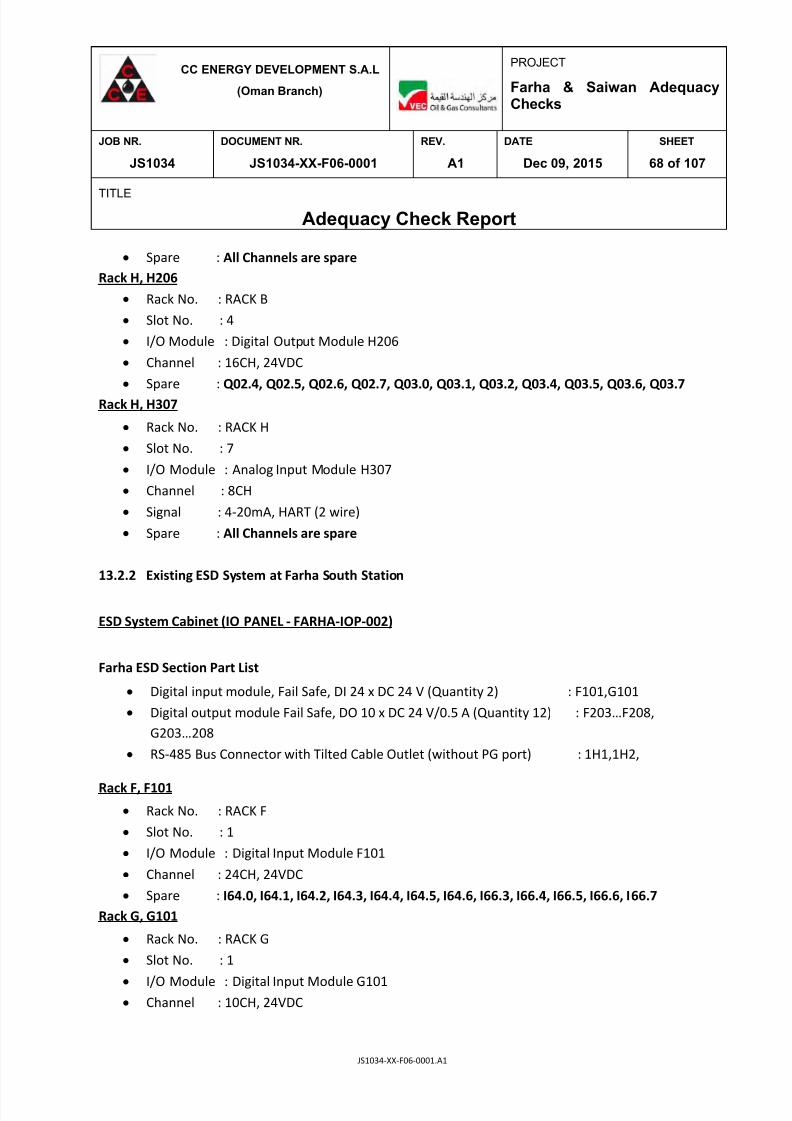
7/25/2019 JS1034-XX-F06-0001. A1
http://slidepdf.com/reader/full/js1034-xx-f06-0001-a1 68/107
CC ENERGY DEVELOPMENT S.A.L
(Oman Branch)
PROJECT
Farha & Saiwan AdequacyChecks
JOB NR. DOCUMENT NR. REV. DATE SHEET
JS1034 JS1034-XX-F06-0001 A1 Dec 09, 2015 68 of 107
TITLE
Adequacy Check Report
JS1034-XX-F06-0001.A1
Spare : All Channels are spare
Rack H, H206
Rack No. : RACK B
Slot No. : 4
I/O Module : Digital Output Module H206
Channel : 16CH, 24VDC
Spare : Q02.4, Q02.5, Q02.6, Q02.7, Q03.0, Q03.1, Q03.2, Q03.4, Q03.5, Q03.6, Q03.7
Rack H, H307
Rack No. : RACK H
Slot No. : 7
I/O Module : Analog Input Module H307
Channel : 8CH
Signal : 4-20mA, HART (2 wire)
Spare : All Channels are spare
13.2.2 Existing ESD System at Farha South Station
ESD System Cabinet (IO PANEL - FARHA-IOP-002)
Farha ESD Section Part List
Digital input module, Fail Safe, DI 24 x DC 24 V (Quantity 2) : F101,G101
Digital output module Fail Safe, DO 10 x DC 24 V/0.5 A (Quantity 12) : F203…F208,
G203…208
RS-485 Bus Connector with Tilted Cable Outlet (without PG port) :
1H1,1H2,
Rack F, F101
Rack No. : RACK F
Slot No. : 1
I/O Module : Digital Input Module F101
Channel : 24CH, 24VDC
Spare : I64.0, I64.1, I64.2, I64.3, I64.4, I64.5, I64.6, I66.3, I66.4, I66.5, I66.6, I66.7
Rack G, G101
Rack No. : RACK G
Slot No. : 1
I/O Module : Digital Input Module G101 Channel : 10CH, 24VDC

7/25/2019 JS1034-XX-F06-0001. A1
http://slidepdf.com/reader/full/js1034-xx-f06-0001-a1 69/107
CC ENERGY DEVELOPMENT S.A.L
(Oman Branch)
PROJECT
Farha & Saiwan AdequacyChecks
JOB NR. DOCUMENT NR. REV. DATE SHEET
JS1034 JS1034-XX-F06-0001 A1 Dec 09, 2015 69 of 107
TITLE
Adequacy Check Report
JS1034-XX-F06-0001.A1
Spare : I1064.0, I1064.1, I1064.2, I1064.3, I1064.4, I1064.5, I1064.6, I1066.3, I1066.4, ,
, I1066.5, I1066.6, I1066.7
Rack F, F203
Rack No. : RACK F
Slot No. : 3
I/O Module : Digital Output Module F203
Channel : 10CH, 24VDC
Spare : Q81.1
Rack G, G203
Rack No. : RACK 5
Slot No. : 3
I/O Module : Digital Output Module F203
Channel : 16CH, 24VDC
Spare : Q1081.1
Rack F, F204
Rack No. : RACK F
Slot No. : 4
I/O Module : Digital Output Module F204
Channel : 10CH, 24VDC
Spare : Q88.7, Q89.0, Q89.1
Rack G, G204
Rack No. : RACK G
Slot No. : 4
I/O Module : Digital Output Module G204
Channel : 10CH, 24VDC
Spare : Q1088.7, Q1089.0, Q1089.1
Rack F, F205
Rack No. : RACK F
Slot No. : 5
I/O Module : Digital Output Module F205
Channel : 10CH, 24VDC
Spare : Q96.0, Q96.1, Q96.2, Q96.3,
Rack G, G205
Rack No. : RACK G
Slot No. : 5 I/O Module : Digital Output Module G205

7/25/2019 JS1034-XX-F06-0001. A1
http://slidepdf.com/reader/full/js1034-xx-f06-0001-a1 70/107
CC ENERGY DEVELOPMENT S.A.L
(Oman Branch)
PROJECT
Farha & Saiwan AdequacyChecks
JOB NR. DOCUMENT NR. REV. DATE SHEET
JS1034 JS1034-XX-F06-0001 A1 Dec 09, 2015 70 of 107
TITLE
Adequacy Check Report
JS1034-XX-F06-0001.A1
Channel : 10CH, 24VDC
Spare : Q1096.0, Q1096.1, Q1096.2, Q1096.3
Rack F, F206
Rack No. : RACK F
Slot No. : 6
I/O Module : Digital Output Module F206
Channel : 10CH, 24VDC
Spare : NO Spares
Rack G, G206
Rack No. : RACK G
Slot No. : 6
I/O Module : Digital Output Module G206
Channel : 10CH, 24VDC
Spare : No Spares
Rack F, F207
Rack No. : RACK F
Slot No. : 7
I/O Module : Digital Output Module F207
Channel : 10CH, 24VDC
Spare : Q113.0, Q113.1
Rack G, G207
Rack No. : RACK G
Slot No. : 7
I/O Module : Digital Output Module G207
Channel : 10CH, 24VDC
Spare : Q1113.0, Q1113.1
Rack F, F208
Rack No. : RACK F
Slot No. : 8
I/O Module : Digital Output Module F208
Channel : 10CH, 24VDC
Spare : Q121.0, Q121.1
Rack G, G208
Rack No. : RACK G Slot No. : 8

7/25/2019 JS1034-XX-F06-0001. A1
http://slidepdf.com/reader/full/js1034-xx-f06-0001-a1 71/107
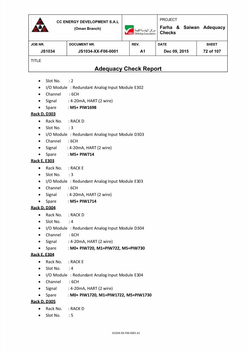
7/25/2019 JS1034-XX-F06-0001. A1
http://slidepdf.com/reader/full/js1034-xx-f06-0001-a1 72/107
CC ENERGY DEVELOPMENT S.A.L
(Oman Branch)
PROJECT
Farha & Saiwan AdequacyChecks
JOB NR. DOCUMENT NR. REV. DATE SHEET
JS1034 JS1034-XX-F06-0001 A1 Dec 09, 2015 72 of 107
TITLE
Adequacy Check Report
JS1034-XX-F06-0001.A1
Slot No. : 2
I/O Module : Redundant Analog Input Module E302
Channel : 6CH
Signal : 4-20mA, HART (2 wire)
Spare : M5+ PIW1698
Rack D, D303
Rack No. : RACK D
Slot No. : 3
I/O Module : Redundant Analog Input Module D303
Channel : 6CH
Signal : 4-20mA, HART (2 wire)
Spare : M5+ PIW714
Rack E, E303
Rack No. : RACK E
Slot No. : 3
I/O Module : Redundant Analog Input Module E303
Channel : 6CH
Signal : 4-20mA, HART (2 wire)
Spare : M5+ PIW1714
Rack D, D304
Rack No. : RACK D
Slot No. : 4
I/O Module : Redundant Analog Input Module D304
Channel : 6CH
Signal : 4-20mA, HART (2 wire)
Spare : M0+ PIW720, M1+PIW722, M5+PIW730
Rack E, E304
Rack No. : RACK E
Slot No. : 4
I/O Module : Redundant Analog Input Module E304
Channel : 6CH
Signal : 4-20mA, HART (2 wire)
Spare : M0+ PIW1720, M1+PIW1722, M5+PIW1730
Rack D, D305
Rack No. : RACK D Slot No. : 5
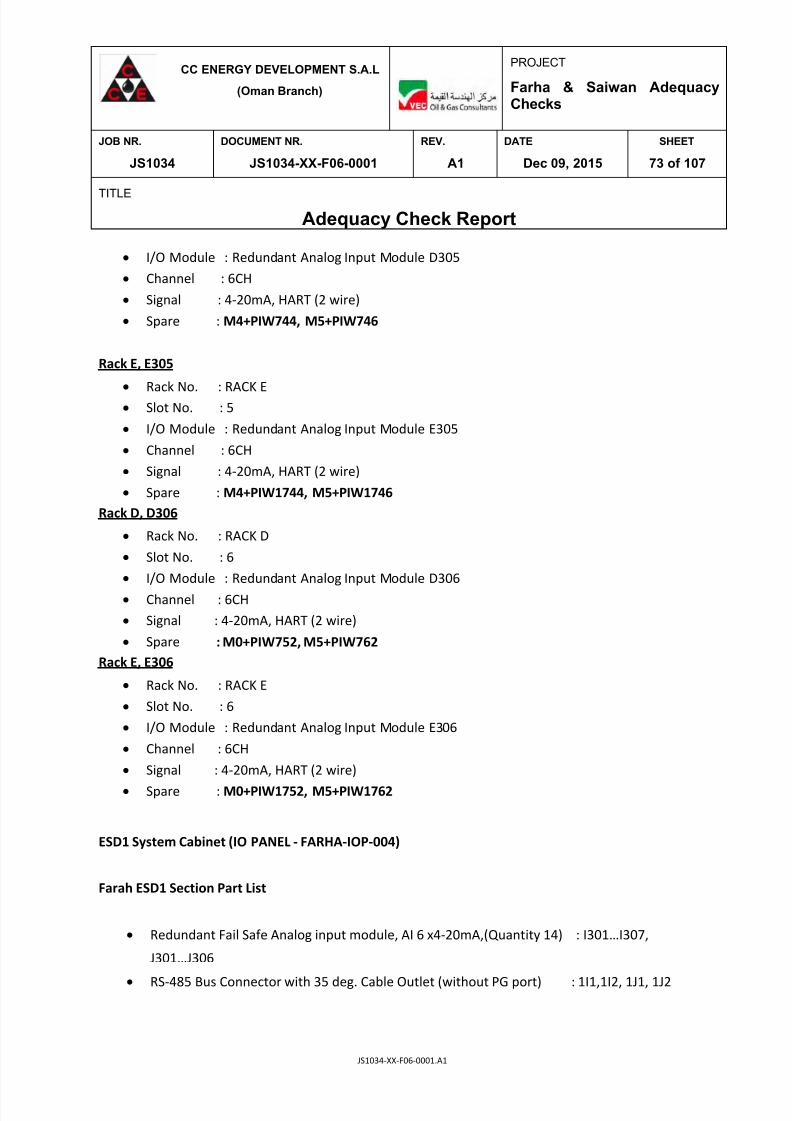
7/25/2019 JS1034-XX-F06-0001. A1
http://slidepdf.com/reader/full/js1034-xx-f06-0001-a1 73/107
CC ENERGY DEVELOPMENT S.A.L
(Oman Branch)
PROJECT
Farha & Saiwan AdequacyChecks
JOB NR. DOCUMENT NR. REV. DATE SHEET
JS1034 JS1034-XX-F06-0001 A1 Dec 09, 2015 73 of 107
TITLE
Adequacy Check Report
JS1034-XX-F06-0001.A1
I/O Module : Redundant Analog Input Module D305
Channel : 6CH
Signal : 4-20mA, HART (2 wire)
Spare : M4+PIW744, M5+PIW746
Rack E, E305
Rack No. : RACK E Slot No. : 5
I/O Module : Redundant Analog Input Module E305
Channel : 6CH
Signal : 4-20mA, HART (2 wire)
Spare : M4+PIW1744, M5+PIW1746
Rack D, D306
Rack No. : RACK D
Slot No. : 6
I/O Module : Redundant Analog Input Module D306
Channel : 6CH
Signal : 4-20mA, HART (2 wire)
Spare : M0+PIW752, M5+PIW762
Rack E, E306
Rack No. : RACK E
Slot No. : 6
I/O Module : Redundant Analog Input Module E306
Channel : 6CH
Signal : 4-20mA, HART (2 wire)
Spare : M0+PIW1752, M5+PIW1762
ESD1 System Cabinet (IO PANEL - FARHA-IOP-004)
Farah ESD1 Section Part List
Redundant Fail Safe Analog input module, AI 6 x4-20mA,(Quantity 14) : I301…I307,
J301…J306
RS-485 Bus Connector with 35 deg. Cable Outlet (without PG port) : 1I1,1I2, 1J1, 1J2

7/25/2019 JS1034-XX-F06-0001. A1
http://slidepdf.com/reader/full/js1034-xx-f06-0001-a1 74/107
CC ENERGY DEVELOPMENT S.A.L
(Oman Branch)
PROJECT
Farha & Saiwan AdequacyChecks
JOB NR. DOCUMENT NR. REV. DATE SHEET
JS1034 JS1034-XX-F06-0001 A1 Dec 09, 2015 74 of 107
TITLE
Adequacy Check Report
JS1034-XX-F06-0001.A1
Rack I, I301
Rack No. : RACK I
Slot No. : 1
I/O Module : Redundant Analog Input Module I301
Channel : 6CH
Signal : 4-20mA, HART (2 wire)
Spare : M5+PIW794
Rack J, J301
Rack No. : RACK J
Slot No. : 1
I/O Module : Redundant Analog Input Module J301
Channel : 6CH
Signal : 4-20mA, HART (2 wire)
Spare : M5+PIW1794
Rack I, I302
Rack No. : RACK I
Slot No. : 2
I/O Module : Redundant Analog Input Module I302
Channel : 6CH
Signal : 4-20mA, HART (2 wire)
Spare : M4+ PIW808, M5+PIW810
Rack J, J302
Rack No. : RACK J
Slot No. : 2
I/O Module : Redundant Analog Input Module J302
Channel : 6CH
Signal : 4-20mA, HART (2 wire)
Spare : M4+ PIW1808, M5+PIW1810
Rack I, I303
Rack No. : RACK I
Slot No. : 3
I/O Module : Redundant Analog Input Module I303
Channel : 6CH
Signal : 4-20mA, HART (2 wire) Spare : M4+ PIW824, M5+PIW826

7/25/2019 JS1034-XX-F06-0001. A1
http://slidepdf.com/reader/full/js1034-xx-f06-0001-a1 75/107
CC ENERGY DEVELOPMENT S.A.L
(Oman Branch)
PROJECT
Farha & Saiwan AdequacyChecks
JOB NR. DOCUMENT NR. REV. DATE SHEET
JS1034 JS1034-XX-F06-0001 A1 Dec 09, 2015 75 of 107
TITLE
Adequacy Check Report
JS1034-XX-F06-0001.A1
Rack J, J303
Rack No. : RACK J
Slot No. : 3
I/O Module : Redundant Analog Input Module J303
Channel : 6CH
Signal : 4-20mA, HART (2 wire)
Spare : M4+ PIW824, M5+PIW826
Rack I, I304
Rack No. : RACK I
Slot No. : 4
I/O Module : Redundant Analog Input Module I304
Channel : 6CH
Signal : 4-20mA, HART (2 wire)
Spare : M4+ PIW840, M5+PIW842
Rack J, J304
Rack No. : RACK J
Slot No. : 4
I/O Module : Redundant Analog Input Module J304
Channel : 6CH
Signal : 4-20mA, HART (2 wire)
Spare : M4+ PIW1840, M5+PIW1842
Rack I, I305
Rack No. : RACK I
Slot No. : 5
I/O Module : Redundant Analog Input Module I305
Channel : 6CH
Signal : 4-20mA, HART (2 wire)
Spare : M5+PIW858
Rack J, J305
Rack No. : RACK J
Slot No. : 5
I/O Module : Redundant Analog Input Module J305
Channel : 6CH
Signal : 4-20mA, HART (2 wire)
Spare : M5+PIW1858Rack I, I306

7/25/2019 JS1034-XX-F06-0001. A1
http://slidepdf.com/reader/full/js1034-xx-f06-0001-a1 76/107
CC ENERGY DEVELOPMENT S.A.L
(Oman Branch)
PROJECT
Farha & Saiwan AdequacyChecks
JOB NR. DOCUMENT NR. REV. DATE SHEET
JS1034 JS1034-XX-F06-0001 A1 Dec 09, 2015 76 of 107
TITLE
Adequacy Check Report
JS1034-XX-F06-0001.A1
Rack No. : RACK I
Slot No. : 6
I/O Module : Redundant Analog Input Module J306
Channel : 6CH
Signal : 4-20mA, HART (2 wire)
Spare : No Spares
Rack J, J306
Rack No. : RACK J
Slot No. : 6
I/O Module : Redundant Analog Input Module J306
Channel : 6CH
Signal : 4-20mA, HART (2 wire)
Spare : No Spares
Rack I, I307
Rack No. : RACK I
Slot No. : 7
I/O Module : Redundant Analog Input Module I307
Channel : 6CH
Signal : 4-20mA, HART (2 wire)
Spare : M5+PIW890
Rack J, J307
Rack No. : RACK J
Slot No. : 7
I/O Module : Redundant Analog Input Module J307
Channel : 6CH
Signal : 4-20mA, HART (2 wire)
Spare : M5+PIW1890

7/25/2019 JS1034-XX-F06-0001. A1
http://slidepdf.com/reader/full/js1034-xx-f06-0001-a1 77/107
CC ENERGY DEVELOPMENT S.A.L
(Oman Branch)
PROJECT
Farha & Saiwan AdequacyChecks
JOB NR. DOCUMENT NR. REV. DATE SHEET
JS1034 JS1034-XX-F06-0001 A1 Dec 09, 2015 77 of 107
TITLE
Adequacy Check Report
JS1034-XX-F06-0001.A1
13.3 Available Space in FES Control Room for System Cabinet and HMI
Farha South Station Control Room has sufficient space for putting new System Cabinets/
Marshalling Cabinets for DCS/ESD/FGS system.
Fig.13.3.1 Space available for new System cabinets and Marshalling Cabinets (DCS/ESD/FGS) at FSS

7/25/2019 JS1034-XX-F06-0001. A1
http://slidepdf.com/reader/full/js1034-xx-f06-0001-a1 78/107
CC ENERGY DEVELOPMENT S.A.L
(Oman Branch)
PROJECT
Farha & Saiwan AdequacyChecks
JOB NR. DOCUMENT NR. REV. DATE SHEET
JS1034 JS1034-XX-F06-0001 A1 Dec 09, 2015 78 of 107
TITLE
Adequacy Check Report
JS1034-XX-F06-0001.A1
Fig.13.3.2. Available Space for putting new HMI (operator work station) at Farha South Station
Control Room at FSS
13.4 Control and ESD System at Saiwan East Station
13.4.1 Existing DCS System at Saiwan East Station
The Existing Saiwan Control System server (DCS System) for Saiwan East Station is SIEMENS -
SIMATIC PCS 7 Process Control System design Modular S7-400 range. S7-400 System contains
ET 200M I/O communication module, includes with Process Control Function and Safety
Function.

7/25/2019 JS1034-XX-F06-0001. A1
http://slidepdf.com/reader/full/js1034-xx-f06-0001-a1 79/107
CC ENERGY DEVELOPMENT S.A.L
(Oman Branch)
PROJECT
Farha & Saiwan AdequacyChecks
JOB NR. DOCUMENT NR. REV. DATE SHEET
JS1034 JS1034-XX-F06-0001 A1 Dec 09, 2015 79 of 107
TITLE
Adequacy Check Report
JS1034-XX-F06-0001.A1
Saiwan Control System has one DCS System Cabinet (CPU/IO PANEL - SAIWAN-IOP-001).After
checking existing DCS Process Control system cabinets (CPU/ IO PANEL-SAIWAN-IOP-001),
there is sufficient spares slots available for inclusion of new cards to interface new signals.
Existing Marshalling Cabinets at Saiwan East Station Control Room (MARSHALLING PANEL-
SAIWAM-MAR-002/003/004) have spare space for putting new Terminal Board.
13.4.2 Existing ESD System at Saiwan East Station
The Existing ESD/FGS System for Saiwan East Station is SIEMENS -SIMATIC PCS 7 Process
Control System design Modular S7-400 range. S7-400 System contains ET 200M I/O
communication module, includes with Process Control Function and Safety Function.
Saiwan has three ESD System Cabinets (IO PANEL - SAIWAN-IOP-002/003/004). After checking
an existing ESD/FGS system cabinet (CPU/IO PANEL-730-FG-001), there are sufficient spare
slots available in Rack for inclusion of new cards to interface new signals.
The table overleaf shows the Spares in DCS /ESD/FGS system cabinets in Saiwan East Station.

7/25/2019 JS1034-XX-F06-0001. A1
http://slidepdf.com/reader/full/js1034-xx-f06-0001-a1 80/107
CC ENERGY DEVELOPMENT S.A.L
(Oman Branch)
PROJECT
Farha & Saiwan AdequacyChecks
JOB NR. DOCUMENT NR. REV. DATE SHEET
JS1034 JS1034-XX-F06-0001 A1 Dec 09, 2015 80 of 107
TITLE
Adequacy Check Report
JS1034-XX-F06-0001.A1
S/N SYSTEM CABINET NO. SPARE “RACKS” SPARE “SLOTS”
1 CPU/IO
PANEL-730-FG-001
RACK 1 NO SPARE SLOTS
AVAILABLE
2 CPU/IO PANEL - SAIWAN-IOP-
001
(DCS)
NO SPARE RACKS
AVAILABLE
RACK B
SLOT 9, SLOT 10
RACK C
SLOT 8, SLOT 9, SLOT 10
RACK D
SLOT 9, SLOT 10
3 CPU/IO PANEL - SAIWAN-IOP-
002 (ESD)
NO SPARE RACKS
AVAILABLE
NO SPARE SLOTS
AVAILABLE
4 CPU/IO PANEL - SAIWAN-IOP-
003(ESD)
NO SPARE RACKS
AVAILABLE
RACK E
SLOT 9, SLOT 10
RACK F
SLOT 9, SLOT 10
13.5 Adequacy Evaluation at Saiwan East Station
13.5.1 Existing DCS System at Saiwan East Station
DCS System Cabinet (CPU/IO PANEL - SAIWAN-IOP-001)
Saiwan DCS Section Part List
Backup Battery, Type AA, 1.9 Ah (Quantity 4) : PS1, PS2
Digital input module, DI 32 x DC 24 V (Quantity 4) : B101,B102,B103,B104
Digital output module, DO 16 x DC 24 V/0.5 A (Quantity 1) : B205
Analog input module, AI 8 x4-20mA, 4W/2W, HART (Quantity 8): B306, B307, B308, C301
C301, C302, C303, C304, C305

7/25/2019 JS1034-XX-F06-0001. A1
http://slidepdf.com/reader/full/js1034-xx-f06-0001-a1 81/107
CC ENERGY DEVELOPMENT S.A.L
(Oman Branch)
PROJECT
Farha & Saiwan AdequacyChecks
JOB NR. DOCUMENT NR. REV. DATE SHEET
JS1034 JS1034-XX-F06-0001 A1 Dec 09, 2015 81 of 107
TITLE
Adequacy Check Report
JS1034-XX-F06-0001.A1
Analog Output module, AO 8 x4-20mA, HART(Quantity 4) : D401, D402, D403, D404
RS-485 Bus Connector with Tilted Cable Outlet (without PG port): 1B1,1B2,1C1,1C2, 1D1, 1D2
RS-485 Bus Connector with 35° Cable Outlet (with PG port) : CPU1;CPU2
PROFIBUS FastConnect bus cable, 2-core, shielded (Quantity 20) : CPU1, CPU2
DCS Module Disposition
Saiwan DCS Section has Four Racks: RACK A1, RACK A2, RACK B, RACK C AND RACK D. Rack A1 and
Rack A2 has nine slots, Slot 1, 2 reserved for 24 VDC Power Supply, Slot 3,4 reserved for CPU, Slot
5 for CP and Slot 6,7,8,9 are spare slots available. Rack B, Rack C and Rack D has Active Bus Module
for I/O Modules (DI, DO, AI, AO) 4-20 mA HART protocol. Rack B, C and D communicates with RS-
485 Bus Connector with Profibus Link to Rack A1 and Rack A2.
The following information shows the Spare Channels in Slots of RACK B and C in Saiwan DCS System
Cabinet (CPU/IO PANEL - SAIWAN-IOP-001).
Rack B, B101
Rack No. : RACK B
Slot No. : 1
I/O Module : Digital Input Module B101
Channel : 32CH, 24VDC
Spare : I3.5, I3.6, I3.7
Rack B, B102
Rack No. : RACK B Slot No. : 2
I/O Module : Digital Input Module B102
Channel : 32CH, 24 VDC
Spare : I4.0, I4.1, I4.2, I4.3, I4.4, I4.5, I4.6, I4.6, I5.0, I5.1, I5.4, I5.5, I5.6, I5.7, I7.7
Rack B, B103
Rack No. : RACK B
Slot No. : 3
I/O Module : Digital Input Module B103
Channel : 32CH, 24 VDC
Spare : I8.3, I8.4, I9.1, I9.2, I11.1, I11.2, I11.3, I11.4

7/25/2019 JS1034-XX-F06-0001. A1
http://slidepdf.com/reader/full/js1034-xx-f06-0001-a1 82/107
CC ENERGY DEVELOPMENT S.A.L
(Oman Branch)
PROJECT
Farha & Saiwan AdequacyChecks
JOB NR. DOCUMENT NR. REV. DATE SHEET
JS1034 JS1034-XX-F06-0001 A1 Dec 09, 2015 82 of 107
TITLE
Adequacy Check Report
JS1034-XX-F06-0001.A1
Rack B, B104
Rack No. : RACK B
Slot No. : 4
I/O Module : Digital Input Module B104
Channel : 32CH, 24 VDC
Spare : NO Spares
Rack B, B205
Rack No. : RACK B
Slot No. : 5
I/O Module : Digital Input Module B205
Channel : 16CH, 24VDC
Spare : Q01.4, Q01.5, Q01.6, Q01.7
Rack B, B306
Rack No. : RACK B
Slot No. : 6
I/O Module : Analog Input Module B306
Channel : 8CH
Signal : 4-20mA, HART (2 wire)
Spare : M7+ PIW526
Rack B, B307
Rack No. : RACK B
Slot No. : 7
I/O Module : Analog Input Module B307
Channel : 8CH
Signal : 4-20mA, HART (2 wire)
Spare : M7+ PIW542
Rack B, B308
Rack No. : RACK B
Slot No. : 8
I/O Module : Analog Input Module B308
Channel : 8CH
Signal : 4-20mA, HART (2 wire)
Spare : M7+ PIW558
Rack C, C301
Rack No. : RACK C
Slot No. : 1
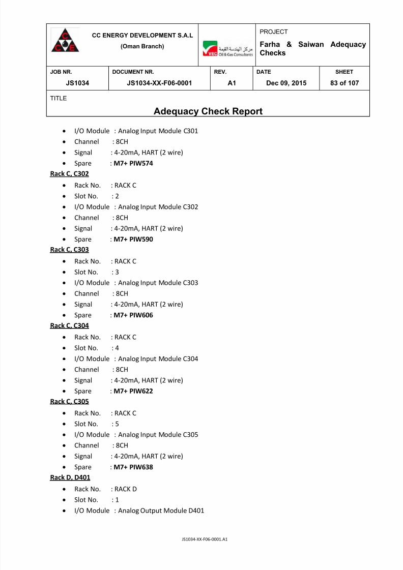
7/25/2019 JS1034-XX-F06-0001. A1
http://slidepdf.com/reader/full/js1034-xx-f06-0001-a1 83/107
CC ENERGY DEVELOPMENT S.A.L
(Oman Branch)
PROJECT
Farha & Saiwan AdequacyChecks
JOB NR. DOCUMENT NR. REV. DATE SHEET
JS1034 JS1034-XX-F06-0001 A1 Dec 09, 2015 83 of 107
TITLE
Adequacy Check Report
JS1034-XX-F06-0001.A1
I/O Module : Analog Input Module C301
Channel : 8CH
Signal : 4-20mA, HART (2 wire)
Spare : M7+ PIW574
Rack C, C302
Rack No. : RACK C
Slot No. : 2
I/O Module : Analog Input Module C302
Channel : 8CH
Signal : 4-20mA, HART (2 wire)
Spare : M7+ PIW590
Rack C, C303
Rack No. : RACK C
Slot No. : 3
I/O Module : Analog Input Module C303
Channel : 8CH
Signal : 4-20mA, HART (2 wire)
Spare : M7+ PIW606
Rack C, C304
Rack No. : RACK C
Slot No. : 4
I/O Module : Analog Input Module C304
Channel : 8CH
Signal : 4-20mA, HART (2 wire)
Spare : M7+ PIW622
Rack C, C305
Rack No. : RACK C
Slot No. : 5
I/O Module : Analog Input Module C305
Channel : 8CH
Signal : 4-20mA, HART (2 wire)
Spare : M7+ PIW638
Rack D, D401
Rack No. : RACK D
Slot No. : 1 I/O Module : Analog Output Module D401
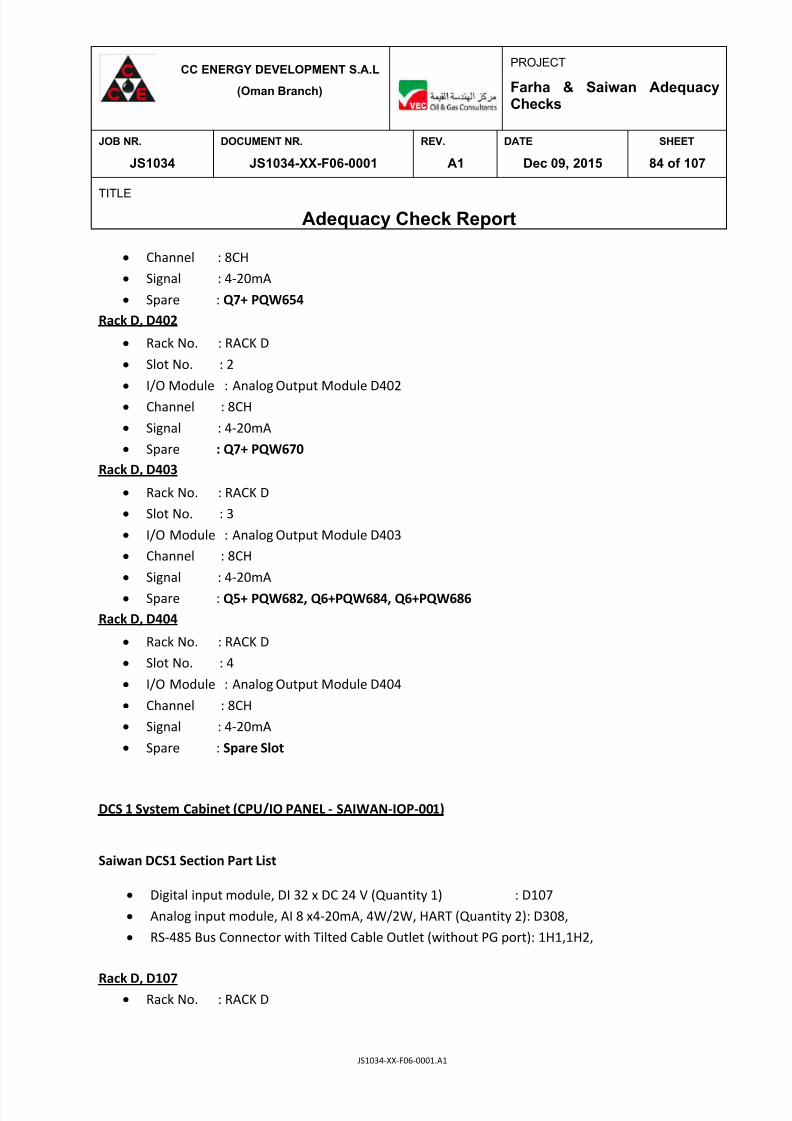
7/25/2019 JS1034-XX-F06-0001. A1
http://slidepdf.com/reader/full/js1034-xx-f06-0001-a1 84/107
CC ENERGY DEVELOPMENT S.A.L
(Oman Branch)
PROJECT
Farha & Saiwan AdequacyChecks
JOB NR. DOCUMENT NR. REV. DATE SHEET
JS1034 JS1034-XX-F06-0001 A1 Dec 09, 2015 84 of 107
TITLE
Adequacy Check Report
JS1034-XX-F06-0001.A1
Channel : 8CH
Signal : 4-20mA
Spare : Q7+ PQW654
Rack D, D402
Rack No. : RACK D
Slot No. : 2
I/O Module : Analog Output Module D402
Channel : 8CH
Signal : 4-20mA
Spare : Q7+ PQW670
Rack D, D403
Rack No. : RACK D
Slot No. : 3
I/O Module : Analog Output Module D403
Channel : 8CH
Signal : 4-20mA
Spare : Q5+ PQW682, Q6+PQW684, Q6+PQW686
Rack D, D404
Rack No. : RACK D
Slot No. : 4
I/O Module : Analog Output Module D404
Channel : 8CH
Signal : 4-20mA
Spare : Spare Slot
DCS 1 System Cabinet (CPU/IO PANEL - SAIWAN-IOP-001)
Saiwan DCS1 Section Part List
Digital input module, DI 32 x DC 24 V (Quantity 1) : D107
Analog input module, AI 8 x4-20mA, 4W/2W, HART (Quantity 2): D308,
RS-485 Bus Connector with Tilted Cable Outlet (without PG port):
1H1,1H2,
Rack D, D107 Rack No. : RACK D

7/25/2019 JS1034-XX-F06-0001. A1
http://slidepdf.com/reader/full/js1034-xx-f06-0001-a1 85/107
CC ENERGY DEVELOPMENT S.A.L
(Oman Branch)
PROJECT
Farha & Saiwan AdequacyChecks
JOB NR. DOCUMENT NR. REV. DATE SHEET
JS1034 JS1034-XX-F06-0001 A1 Dec 09, 2015 85 of 107
TITLE
Adequacy Check Report
JS1034-XX-F06-0001.A1
Slot No. : 7
I/O Module : Digital Input Module D107
Channel : 16CH, 24VDC
Spare : I17.6, I17.7, I18.0 to I18.7, I19.0 to I19.7
Rack D, D308
Rack No. : RACK H
Slot No. : 8
I/O Module : Analog Input Module D308
Channel : 8CH
Signal : 4-20mA, HART (2 wire)
Spare : M1+ PIW642, M2+ PIW646, M4+ PIW648,M5+PIW650,M6+PIW652,M7+PIW654
ESD System Cabinet (IO PANEL - SAIWAN-IOP-002)
Saiwan ESD Section Part List
Digital input module, Fail Safe, DI 24 x DC 24 V (Quantity 2) : G101,H101 Digital output module Fail Safe, DO 10 x DC 24 V/0.5 A (Quantity 12) : G203…G208,
H203…H208
RS-485 Bus Connector with Tilted Cable Outlet (without PG port) :
1E1, 1E2, 1F1, 1F2,
1G1,1G2,1H1,1H2
Rack G, G101
Rack No. : RACK G
Slot No. : 1
I/O Module : Redundant Digital Input Module G101
Channel : 24CH, 24VDC
Spare : I64.6, I64.7, I65.0 to I65.7, I66.0, I65.7
Rack H, H101
Rack No. : RACK H
Slot No. : 1
I/O Module : Redundant Digital Input Module H101
Channel : 24CH, 24VDC
Spare : Spare Slot
Rack G, G203
Rack No. : RACK G
Slot No. : 3

7/25/2019 JS1034-XX-F06-0001. A1
http://slidepdf.com/reader/full/js1034-xx-f06-0001-a1 86/107
CC ENERGY DEVELOPMENT S.A.L
(Oman Branch)
PROJECT
Farha & Saiwan AdequacyChecks
JOB NR. DOCUMENT NR. REV. DATE SHEET
JS1034 JS1034-XX-F06-0001 A1 Dec 09, 2015 86 of 107
TITLE
Adequacy Check Report
JS1034-XX-F06-0001.A1
I/O Module : Digital Output Module G203
Channel : 10CH, 24VDC
Spare : Q81.0, Q81.1
Rack H, H203
Rack No. : RACK H
Slot No. : 3
I/O Module : Digital Output Module H203
Channel : 10CH, 24VDC
Spare : Q1081.1
Rack G, G204
Rack No. : RACK G
Slot No. : 4
I/O Module : Digital Output Module G204
Channel : 10CH, 24VDC
Spare : Q89.0, Q89.1
Rack H, H204
Rack No. : RACK H
Slot No. : 4
I/O Module : Digital Output Module H204
Channel : 10CH, 24VDC
Spare : Q1089.0, Q1089.1
Rack G, G205
Rack No. : RACK G
Slot No. : 5
I/O Module : Digital Output Module G205
Channel : 10CH, 24VDC Spare : Q96.0 to Q96.5
Rack H, H205
Rack No. : RACK H
Slot No. : 5
I/O Module : Digital Output Module H205
Channel : 10CH, 24VDC
Spare : Q1096.0 to Q1096.5
Rack G, G206
Rack No. : RACK G

7/25/2019 JS1034-XX-F06-0001. A1
http://slidepdf.com/reader/full/js1034-xx-f06-0001-a1 87/107
CC ENERGY DEVELOPMENT S.A.L
(Oman Branch)
PROJECT
Farha & Saiwan AdequacyChecks
JOB NR. DOCUMENT NR. REV. DATE SHEET
JS1034 JS1034-XX-F06-0001 A1 Dec 09, 2015 87 of 107
TITLE
Adequacy Check Report
JS1034-XX-F06-0001.A1
Slot No. : 6
I/O Module : Digital Output Module G206
Channel : 10CH, 24VDC
Spare : Q105.1
Rack H, H206
Rack No. : RACK H
Slot No. : 6
I/O Module : Digital Output Module H206
Channel : 10CH, 24VDC
Spare : Q1105.1
Rack G, G207
Rack No. : RACK G
Slot No. : 7
I/O Module : Digital Output Module G207
Channel : 10CH, 24VDC
Spare : Q112.0, Q112.3, Q112.6, Q112.7, Q113.0, Q113.1
Rack H, H207
Rack No. : RACK H
Slot No. : 7
I/O Module : Digital Output Module H207
Channel : 10CH, 24VDC
Spare : Q1112.0, Q1112.3, Q1112.6, Q1112.7, Q1113.0, Q1113.1
Rack G, G208
Rack No. : RACK G
Slot No. : 8
I/O Module : Digital Output Module G208 Channel : 10CH, 24VDC
Spare : Q121.1
Rack H, H208
Rack No. : RACK H
Slot No. : 8
I/O Module : Digital Output Module GH08
Channel : 10CH, 24VDC
Spare : Q1121.1
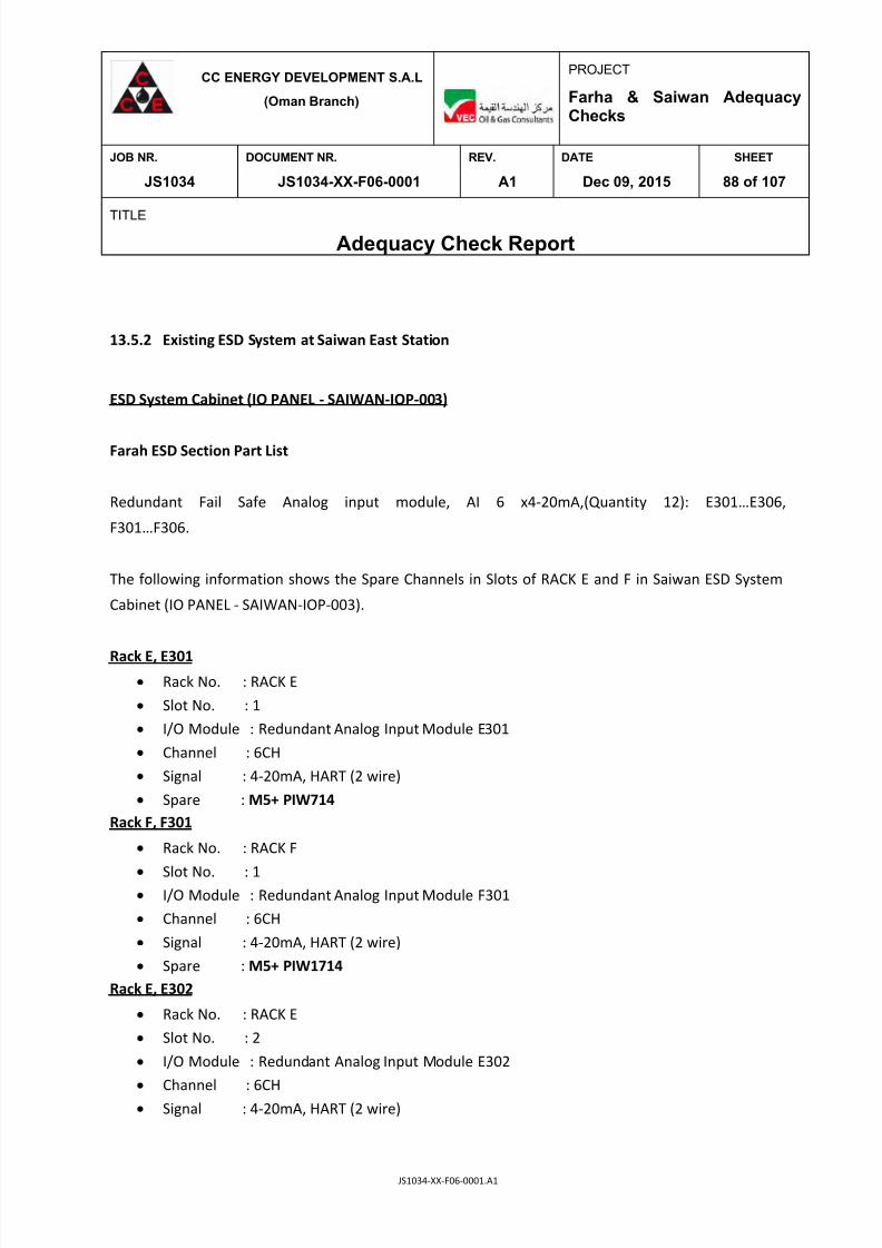
7/25/2019 JS1034-XX-F06-0001. A1
http://slidepdf.com/reader/full/js1034-xx-f06-0001-a1 88/107
CC ENERGY DEVELOPMENT S.A.L
(Oman Branch)
PROJECT
Farha & Saiwan AdequacyChecks
JOB NR. DOCUMENT NR. REV. DATE SHEET
JS1034 JS1034-XX-F06-0001 A1 Dec 09, 2015 88 of 107
TITLE
Adequacy Check Report
JS1034-XX-F06-0001.A1
13.5.2 Existing ESD System at Saiwan East Station
ESD System Cabinet (IO PANEL - SAIWAN-IOP-003)
Farah ESD Section Part List
Redundant Fail Safe Analog input module, AI 6 x4-20mA,(Quantity 12): E301…E306,
F301…F306.
The following information shows the Spare Channels in Slots of RACK E and F in Saiwan ESD System
Cabinet (IO PANEL - SAIWAN-IOP-003).
Rack E, E301
Rack No. : RACK E
Slot No. : 1
I/O Module : Redundant Analog Input Module E301
Channel : 6CH
Signal : 4-20mA, HART (2 wire)
Spare : M5+ PIW714
Rack F, F301
Rack No. : RACK F
Slot No. : 1 I/O Module : Redundant Analog Input Module F301
Channel : 6CH
Signal : 4-20mA, HART (2 wire)
Spare : M5+ PIW1714
Rack E, E302
Rack No. : RACK E
Slot No. : 2
I/O Module : Redundant Analog Input Module E302
Channel : 6CH
Signal : 4-20mA, HART (2 wire)

7/25/2019 JS1034-XX-F06-0001. A1
http://slidepdf.com/reader/full/js1034-xx-f06-0001-a1 89/107
CC ENERGY DEVELOPMENT S.A.L
(Oman Branch)
PROJECT
Farha & Saiwan AdequacyChecks
JOB NR. DOCUMENT NR. REV. DATE SHEET
JS1034 JS1034-XX-F06-0001 A1 Dec 09, 2015 89 of 107
TITLE
Adequacy Check Report
JS1034-XX-F06-0001.A1
Spare : M5+ PIW730
Rack E, E303
Rack No. : RACK E
Slot No. : 3
I/O Module : Redundant Analog Input Module E303
Channel : 6CH
Signal : 4-20mA, HART (2 wire)
Spare : M5+ PIW746
Rack F, F303
Rack No. : RACK F
Slot No. : 3
I/O Module : Redundant Analog Input Module F303
Channel : 6CH
Signal : 4-20mA, HART (2 wire)
Spare : M5+ PIW1746
Rack E, E304
Rack No. : RACK E
Slot No. : 4
I/O Module : Redundant Analog Input Module E304
Channel : 6CH
Signal : 4-20mA, HART (2 wire)
Spare : M5+ PIW1714
Rack D, D304
Rack No. : RACK D
Slot No. : 4
I/O Module : Redundant Analog Input Module D304
Channel : 6CH
Signal : 4-20mA, HART (2 wire)
Spare : M0+ PIW720, M1+PIW722, M5+PIW730
Rack D, E304
Rack No. : RACK E
Slot No. : 4
I/O Module : Redundant Analog Input Module E304
Channel : 6CH Signal : 4-20mA, HART (2 wire)

7/25/2019 JS1034-XX-F06-0001. A1
http://slidepdf.com/reader/full/js1034-xx-f06-0001-a1 90/107
CC ENERGY DEVELOPMENT S.A.L
(Oman Branch)
PROJECT
Farha & Saiwan AdequacyChecks
JOB NR. DOCUMENT NR. REV. DATE SHEET
JS1034 JS1034-XX-F06-0001 A1 Dec 09, 2015 90 of 107
TITLE
Adequacy Check Report
JS1034-XX-F06-0001.A1
Spare : M5+PIW762
Rack F, F304
Rack No. : RACK F
Slot No. : 4
I/O Module : Redundant Analog Input Module F304
Channel : 6CH
Signal : 4-20mA, HART (2 wire)
Spare : M5+PIW1762
Rack E, E305
Rack No. : RACK E
Slot No. : 5
I/O Module : Redundant Analog Input Module E305
Channel : 6CH
Signal : 4-20mA, HART (2 wire)
Spare : M5+PIW778
Rack F, F305
Rack No. : RACK F
Slot No. : 5
I/O Module : Redundant Analog Input Module F305
Channel : 6CH
Signal : 4-20mA, HART (2 wire)
Spare : M5+PIW1778
Rack E, E306
Rack No. : RACK E
Slot No. : 6
I/O Module : Redundant Analog Input Module E306
Channel : 6CH
Signal : 4-20mA, HART (2 wire)
Spare : M5+PIW794
Rack F, F306
Rack No. : RACK F
Slot No. : 6
I/O Module : Redundant Analog Input Module F306
Channel : 6CH
Signal : 4-20mA, HART (2 wire) Spare : M5+PIW1794

7/25/2019 JS1034-XX-F06-0001. A1
http://slidepdf.com/reader/full/js1034-xx-f06-0001-a1 91/107
CC ENERGY DEVELOPMENT S.A.L
(Oman Branch)
PROJECT
Farha & Saiwan AdequacyChecks
JOB NR. DOCUMENT NR. REV. DATE SHEET
JS1034 JS1034-XX-F06-0001 A1 Dec 09, 2015 91 of 107
TITLE
Adequacy Check Report
JS1034-XX-F06-0001.A1
Rack E, E307
Rack No. : RACK E
Slot No. : 7
I/O Module : Redundant Analog Input Module E307
Channel : 6CH
Signal : 4-20mA, HART (2 wire)
Spare : M5+PIW810
Rack F F307
Rack No. : RACK F
Slot No. : 7
I/O Module : Redundant Analog Input Module F307
Channel : 6CH
Signal : 4-20mA, HART (2 wire)
Spare : M5+PIW1810
Rack E, E308
Rack No. : RACK E
Slot No. : 8
I/O Module : Redundant Analog Input Module E308
Channel : 6CH
Signal : 4-20mA, HART (2 wire)
Spare : M5+PIW826
Rack F, F308
Rack No. : RACK F
Slot No. : 8
I/O Module : Redundant Analog Input Module F308
Channel : 6CH
Signal : 4-20mA, HART (2 wire)
Spare : M5+PIW1826
ESD1 System Cabinet (IO PANEL - SAIWAN-IOP-004)
Farah ESD1 Section Part List
Redundant Fail Safe Analog input module, AI 6 x4-20mA,(Quantity 4) : G309, G310,
H309, H310

7/25/2019 JS1034-XX-F06-0001. A1
http://slidepdf.com/reader/full/js1034-xx-f06-0001-a1 92/107
CC ENERGY DEVELOPMENT S.A.L
(Oman Branch)
PROJECT
Farha & Saiwan AdequacyChecks
JOB NR. DOCUMENT NR. REV. DATE SHEET
JS1034 JS1034-XX-F06-0001 A1 Dec 09, 2015 92 of 107
TITLE
Adequacy Check Report
JS1034-XX-F06-0001.A1
RS-485 Bus Connector with 35 deg. Cable Outlet (without PG port) :
1I1,1I2, 1J1, 1J2
The following information shows the Spare Channels in Slots of RACK G and H in Saiwan ESD1 System
Cabinet (CPU/IO PANEL - SAIWAN-IOP-001).
Rack G, G309
Rack No. : RACK G
Slot No. : 19
I/O Module : Redundant Analog Input Module G309
Channel : 6CH
Signal : 4-20mA, HART (2 wire)
Spare : M5+PIW794
Rack J, J301
Rack No. : RACK J
Slot No. : 1
I/O Module : Redundant Analog Input Module G309 Channel : 6CH
Signal : 4-20mA, HART (2 wire)
Spare : M5+PIW1794
Rack I, I302
Rack No. : RACK I
Slot No. : 2
I/O Module : Redundant Analog Input Module I302
Channel : 6CH
Signal : 4-20mA, HART (2 wire) Spare : M4+ PIW808, M5+PIW810
Rack J, J302
Rack No. : RACK J
Slot No. : 2
I/O Module : Redundant Analog Input Module J302
Channel : 6CH
Signal : 4-20mA, HART (2 wire)
Spare : M4+ PIW1808, M5+PIW1810
Rack I, I303
Rack No. : RACK I

7/25/2019 JS1034-XX-F06-0001. A1
http://slidepdf.com/reader/full/js1034-xx-f06-0001-a1 93/107
CC ENERGY DEVELOPMENT S.A.L
(Oman Branch)
PROJECT
Farha & Saiwan AdequacyChecks
JOB NR. DOCUMENT NR. REV. DATE SHEET
JS1034 JS1034-XX-F06-0001 A1 Dec 09, 2015 93 of 107
TITLE
Adequacy Check Report
JS1034-XX-F06-0001.A1
Slot No. : 3
I/O Module : Redundant Analog Input Module I303
Channel : 6CH
Signal : 4-20mA, HART (2 wire)
Spare : M4+ PIW824, M5+PIW826
Rack J, J303
Rack No. : RACK J
Slot No. : 3
I/O Module : Redundant Analog Input Module J303
Channel : 6CH
Signal : 4-20mA, HART (2 wire)
Spare : M4+ PIW824, M5+PIW826
Rack I, Module I304
Rack No. : RACK I
Slot No. : 4
I/O Module : Redundant Analog Input Module I304
Channel : 6CH
Signal : 4-20mA, HART (2 wire)
Spare : M4+ PIW840, M5+PIW842
Rack J, J304
Rack No. : RACK J
Slot No. : 4
Channel : 6CH
I/O Module : Redundant Analog Input Module J304
Signal : 4-20mA, HART (2 wire)
Spare : M4+ PIW1840, M5+PIW1842
Rack I, I305
Rack No. : RACK I
Slot No. : 5
I/O Module : Redundant Analog Input Module I305
Channel : 6CH
Signal : 4-20mA, HART (2 wire)
Spare : M5+PIW858
Rack J, J305
Rack No. : RACK I Slot No. : 5
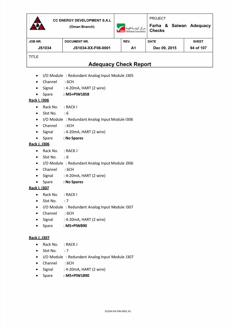
7/25/2019 JS1034-XX-F06-0001. A1
http://slidepdf.com/reader/full/js1034-xx-f06-0001-a1 94/107
CC ENERGY DEVELOPMENT S.A.L
(Oman Branch)
PROJECT
Farha & Saiwan AdequacyChecks
JOB NR. DOCUMENT NR. REV. DATE SHEET
JS1034 JS1034-XX-F06-0001 A1 Dec 09, 2015 94 of 107
TITLE
Adequacy Check Report
JS1034-XX-F06-0001.A1
I/O Module : Redundant Analog Input Module J305
Channel : 6CH
Signal : 4-20mA, HART (2 wire)
Spare : M5+PIW1858
Rack I, I306
Rack No. : RACK I
Slot No. : 6
I/O Module : Redundant Analog Input Module I306
Channel : 6CH
Signal : 4-20mA, HART (2 wire)
Spare : No Spares
Rack J, J306
Rack No. : RACK J
Slot No. : 6
I/O Module : Redundant Analog Input Module J306
Channel : 6CH
Signal : 4-20mA, HART (2 wire)
Spare : No Spares
Rack I, I307
Rack No. : RACK I
Slot No. : 7
I/O Module : Redundant Analog Input Module I307
Channel : 6CH
Signal : 4-20mA, HART (2 wire)
Spare : M5+PIW890
Rack J, J307
Rack No. : RACK J
Slot No. : 7
I/O Module : Redundant Analog Input Module J307
Channel : 6CH
Signal : 4-20mA, HART (2 wire)
Spare : M5+PIW1890

7/25/2019 JS1034-XX-F06-0001. A1
http://slidepdf.com/reader/full/js1034-xx-f06-0001-a1 95/107
CC ENERGY DEVELOPMENT S.A.L
(Oman Branch)
PROJECT
Farha & Saiwan AdequacyChecks
JOB NR. DOCUMENT NR. REV. DATE SHEET
JS1034 JS1034-XX-F06-0001 A1 Dec 09, 2015 95 of 107
TITLE
Adequacy Check Report
JS1034-XX-F06-0001.A1
13.6 Available Space in SES Control Room for System Cabinet
Saiwan East Station Control Room has sufficient space for putting new System Cabinets/
Marshalling Cabinets for DCS/ESD/FGS system.
Fig.13.6.1 Space available for System Cabinets/ Marshalling Cabinets new DCS/ESD/FGS
System at SES

7/25/2019 JS1034-XX-F06-0001. A1
http://slidepdf.com/reader/full/js1034-xx-f06-0001-a1 96/107
CC ENERGY DEVELOPMENT S.A.L
(Oman Branch)
PROJECT
Farha & Saiwan AdequacyChecks
JOB NR. DOCUMENT NR. REV. DATE SHEET
JS1034 JS1034-XX-F06-0001 A1 Dec 09, 2015 96 of 107
TITLE
Adequacy Check Report
JS1034-XX-F06-0001.A1
13.7 Control Valve Adequacy Check
Farha: New Cv for Control Valves
M a s s F l o w r a t e ( k g / h r )
I n l e t P r e s s u r e ( b a r g )
O u t e l t P r e s s u r e (
b a r g )
O p e r a t i n g T e m p . (
D e g C )
M o l e c u l a r w e i g h t
V i s c o c i t y o f g a s
( c P )
V a p o u r P r e s s u r e ( b a r g )
S p e c i f i c H e a t R a t i o C p / C v = K
M a s s D e n s i t y k g
/ m 3
C o m p r e s s i b i l i t y
S p e c i f i c G a r v i t y
C r i t i c a l P r e s s u
r e
M i n .
21.32 4.7 3.987 20 32.5 0.01345 NA 1.252 7.511 0.9786 NA NA 0.354
N o r m .
42.64 4.987 3.987 20 32.5 0.01345 NA 1.254 8.19 0.9767 NA NA 0.582
M a x .
51.168 5 3.987 55 32.5 0.01345 NA 1.254 8.209 0.9841 NA NA 0.694
M i n .
223. 9953 3. 7 0.9868 36. 9 43.53 0 .00972 NA 1. 157 8.237 0. 9445 N A NA 2.3
N o r m .
447. 9905 3. 987 0.9868 67 43.53 0.01063 NA 1. 141 8.089 0. 9514 N A NA 4.435
M a x .
537.5886 4 0.9868 67 43.53 0 .01063 NA 1.141 8.11 0.9513 NA NA 5.373
M i n .
21085.31 4.987 3 .987 20 165.4 3.09 4.986 1 .185 810.7 NA 0.81 50.74 42
N o r m .
42170.63 4.987 3.987 20 165.4 3.09 4.986 1.185 810.7 NA 0.81 50.74 73.253 58
M a x .
50604.75 5 3.987 55 165.4 1.638 4.986 1.186 782.2 NA 0.81 50.74 87.507 62 2. For “normal” & “maximum” controllability, the existing “Trim”
can be re-used, if no concern on minimum control.
M i n .
20861. 32 3. 5 0. 9868 20 170. 527 3. 361299 3. 987 1. 181 813. 5 N A 0. 813 50. 74
N o r m .
41722. 64 3 .987 0. 9868 67 170. 527 1. 419 3. 987 1. 023 774. 5 N A 0. 774 50. 74
M a x .
50067.16 4 0.9868 67 170.527 1.419 3.987 1.023 774.5 NA 0.774 50.74 96.557 80
M i n .
4458.928 4.5 1 20 18.02 1.0017 5 1.135 1011 NA 1.011 NA 2.76 17
N o r m . 8917.855 5 1 20 18.02 1.0017 5 1.135 1011 NA 1.011 NA 5.165 32
M a x .
10701.43 5.5 1 55 18.02 1.0017 5 1.153 984 NA 0.9845 NA 5.88 35
M i n .
1065.5 3 1 20 18.02 1.002 NA 1.1812 1011 NA 1.011 NA 0.781 41
N o r m .
2131 3.5 1 67 18.02 0.417646 NA 1.0226 824.1 NA 0.824 NA 1.144 58
M a x .
2557.2 4 1 55 18.02 0.417646 NA 1.185 975.1 NA 0.975 NA 1.595 61
N o r m .
1471.681 3.98 0.9 63.52 42.282 0.0109 NA 1.147 7.903 0.9556 NA NA 14.811 11
M a x .
1766.017 4 0.9 63.51 42.282 0.0109 NA 1.147 0.186 0.955479 NA NA 115.947 52
6
2 0 1 - L V - 2 0 2 / 2 0 3
Water/
Liquid 4.91
1. Existing “Trim” is not suitable for given new process data for
minimum controllability.
1. Existing “Trim” is not suitable for given new process data for
minimum controllability.
2. For “normal” & “maximum” controllability, the existing “Trim”
can be re-used, if no concern on minimum control.
4
2 0 1 - L V - 2 0 4 A
Oil/
Liquid 136 Existing “Trim” can be re-used.
5
2 0 1 - L V - 1 0 7 A
Water/
Liquid 70.7 Existing “Trim” is not suitable for given process data.
2
2 0 1 - P V - 2 0 2
HC Gas/
Vapour 53.8
Existing “Trim” is not suitable for given process data for Min.
/Norm. /Max. Controllability.
3
2 0 1 - L V - 1 1 0 A
Oil/
Liquid 224
V A L V E O P E N I N G %
R E M A
R K S
1
2 0 1 - P V - 1 0 6 A
HC Gas/
Vapour 70.7
Existing “Trim” is not suitable for given process data for Min.
/Norm. /Max. Controllability.
S / N
T A G N
O .
P r o c e s s F l u
i d / S t a t e
NEW PROCESS CONDITION FARHA
N E W C
A L C U
L A T E D C V
E X I S T I N G R A T E D C V

7/25/2019 JS1034-XX-F06-0001. A1
http://slidepdf.com/reader/full/js1034-xx-f06-0001-a1 97/107
CC ENERGY DEVELOPMENT S.A.L
(Oman Branch)
PROJECT
Farha & Saiwan AdequacyChecks
JOB NR. DOCUMENT NR. REV. DATE SHEET
JS1034 JS1034-XX-F06-0001 A1 Dec 09, 2015 97 of 107
TITLE
Adequacy Check Report
JS1034-XX-F06-0001.A1
Saiwan: New Cv for Control Valves
M a s s F l o w
r a t e ( k g / h r )
I n l e t P r e
s s u r e ( b a r g )
O u t e l t P r e s s u r e ( b a r g )
O p e r a t i n g
T e m p . ( D e g C )
M o l e c u
l a r w e i g h t
V i s c o c i t y o f g a s ( c P )
V a p o u r P r
e s s u r e ( b a r g )
S p e c i f i c H e a
t R a t i o C p / C v = K
M a s s D e
n s i t y k g / m 3
C o m p r e s s i b i l i t y
S p e c i f
i c G a r v i t y
C r i t i c a l P r e s s u r e
M i n .
547.7983 4.5 4 20 27.119 0.01086 NA 1.23736 6.332174 0.968773 NA NA 11.898 52 1. Existing “Trim” is not suitable for given new process data
for minimum controllability.
N o r m .
1095.597 5 4 20 27.119 0.01086 NA 1.23999 6.926838 0.965915 NA NA 16.873 60
M a x .
1314.716 5.5 4 55 27.119 0.01086 NA 27.119 6.647134 0.973976 NA NA 17.649 61 2.
For “normal” & “maximum” controllability, the existing
“Trim” can be re-used, if no concern on minimum control.
M i n .
29535.63 4.5 4 20 214.2 8.53163 5 1.148 852.7 NA 0.8527 51.263
N o r m .
59071.27 5 4 20 214.2 8.48012 5 1.149 852.5 NA 0.8527 51.263
M a x .
70885.52 4.5 4 55 214.2 5.12095 5 1.018 826.5 NA 0.826 51.263 91.366 63
M
i n .
29238. 56 3. 5 1 20 224. 516 9. 34 4 855.954 855.954 N A 0. 855 46.883
N o r m .
58477.13 4 1 67 224.516 4.38 4 819.3 819.3 NA 0.819 46.883
M a x .
70172.55 4.5 1 67 224.516 4.38 4 819.3 819.3 NA 0.819 46.883 93.595 75
M i n .
297.07 3.5 3.5 20 36.719 0.00935 NA 1.184 7.184 0.946 NA NA
N o r m .
594.14 4 3.5 67 36.719 0.01071 NA 1.1449 7.189 0.946 NA NA 12.339
M a x .
712.97 4.5 3.5 67 36.719 0.0107 NA 1.152 7.942 0.946 NA NA 10.542
M i n .
3630.637 3 0.01 20 25.654 0.0112 NA 1.235 4.767 0.978 NA NA 61.357 54 1. Existing “Trim” is not suitable for given new process data
for minimum controllability.
N o r m .
7261.274 3.5 0.09 20 25.654 0.0112 NA 1.235 4.767 0.978 NA NA 113.537 67
M a x .
8713.529 4 0.79 55 25.654 0.0112 NA 1.235 4.767 0.978 NA NA 129.905 71
2. For “normal” & “maximum” controllability, the existing
“Trim” can be re-used, if no concern on minimum control.
M i n .
13978.21 4.5 1 20 18.02 1.002 5 1.131 1011 NA 1.011 220.2 8.657 44 1. Existing “Trim” is not suitable for given new process data
for minimum controllability.
N o r m .
27956.41 5 1 20 18.02 1.002 5 1.131 1011 NA 1.011 220 16.214 59
M a x .
3547.693 5.5 1 20 18.02 1.002 5 1.131 1011 NA 1.011 220.2 18.352 61 2. For “normal” & “maximum” controllability, the existing
“Trim” can be re-used, if no concern on minimum control.
M i n .
1419 3.5 1 20 18.02 1.002 NA 1.131 1011 NA 1.011 NA 1.041 13
N o r m .
2838 4 1 67 18.02 0.41765 NA 1.131 1011 NA 0.824 NA 1.919 26
M a x .
3405.6 4.5 1 55 18.02 0.41765 N A 1.131 1011 NA 0.984 NA 2.126 29
Existing “Trim” is not suitable for given process data.
6
2 0 1 - L V - 0 0 7 A
Water/
Liquid 70.7
7
2 0 0 - L V - 4 0 2 / 4 0 3
Water/
Liquid 17.2
4
2 0 0 - P V - 4 0 2
HC Gas/
Vapour 53.84
5
4 0 2 - P V - 4 0 1
HC Gas/
Vapour 224
2
2 0 0 - L V - - 0 1 0 A
Oil/
Liquid 224
3
2 0 0 - L V - 4 0 4 A
Oil/
Liquid 136
V A L
V E O P E N I N G %
R E M A R K S
1
2 0 0 - P V - 0 0 6 A
HC Gas/
Vapour 70.7
S / N
T A G N O .
P r o c
e s s F l u i d / S t a t e
NEW PROCESS CONDITION SAIWAN
N E W C
A L C U L A T E D C V
E X I S T I N G R A T E D C V

7/25/2019 JS1034-XX-F06-0001. A1
http://slidepdf.com/reader/full/js1034-xx-f06-0001-a1 98/107
CC ENERGY DEVELOPMENT S.A.L
(Oman Branch)
PROJECT
Farha & Saiwan AdequacyChecks
JOB NR. DOCUMENT NR. REV. DATE SHEET
JS1034 JS1034-XX-F06-0001 A1 Dec 09, 2015 98 of 107
TITLE
Adequacy Check Report
JS1034-XX-F06-0001.A1
14 ELECTRICAL ADEQUACY CHECKS
Introduction
As part of Farha & Saiwan Plant Expansion, an adequacy study on the existing electrical system at
Farha & Saiwan was carried out. The study was mainly aimed to check the available spare
capacity and spare feeders at Farha & Saiwan to cater for the proposed additional loads. The
study consists of the following;
Adequacy of Existing Electrical Infrastructure at Farha
The electrical power system at Farha consists of mainly one switch gear room with one
switchboard (921-EM-002).
415V LV Switch Boards, 921-EM-002
The switch board (921-EM-002) at Farha is fed by 3* 1000 kVA 415V DG sets. The whole facility
loads are connected to this switch board. 18 spare feeders of various ratings and 5 vacant
compartments are available on this LV Switchboard. Extension of LV switchboard, 921-EM-002 is
possible with addition of one cubicle at one end as shown in the site visit report.
The proposal is made for the addition of 4*30kW Heater Treater Blowers (2 duty & 2 standby),
3*0.18kW Demulsifier Dosing Pump (2 duty & 1 standby) and an Instrument Air Package of 65kW
as part of Train 2 and Train 3 expansion. All these new electrical equipments shall be electrified
with the suitable spare feeders from the available 18 spare feeders as listed overleaf.

7/25/2019 JS1034-XX-F06-0001. A1
http://slidepdf.com/reader/full/js1034-xx-f06-0001-a1 99/107
CC ENERGY DEVELOPMENT S.A.L
(Oman Branch)
PROJECT
Farha & Saiwan AdequacyChecks
JOB NR. DOCUMENT NR. REV. DATE SHEET
JS1034 JS1034-XX-F06-0001 A1 Dec 09, 2015 99 of 107
TITLE
Adequacy Check Report
JS1034-XX-F06-0001.A1
Sl. No. Spare feeders Rating Vacant
Compartment
1 Q 101 15kW Q 807
2 Q 106 55kW Q 1706
3 Q 107 1.5kW Q 1707
4 Q 205 3kW Q 1904
5 Q 207 3.7kW Q 1905
6 Q 301 5.5kW 7 Q 405 7.5kW
8 Q 407 10A
9 Q 501 30kW
10 Q 601 30kW
11 Q 702 10kW
12 Q 1301 22kW
13 Q 1306 0.55kW
14 Q 1407 3kW
15 Q 1502 3.7kW
16 Q 1607 70A
17 Q 1705 100A
18 Q 1804 25A
Diesel Generators (DG set) 1000kVA, 415V
In Farha facility, there are three 1000KVA, 415V Generators. All three DG sets are manufactured
by FG Wilson (Engineering) Ltd, United Kingdom, in the year 2010.
Based on available electrical load schedule (Doc. no.: JS1034-F-E-08-0001)A26
, the connected plant
peak load including the recently added new loads under other projects is approximately
2105.03kVA (@ 0.8 p.f), whereas the total installed capacity of DG is 3000kVA. The spare
capacity of the plant is 894.97 kVA (@ 0.8 p.f), which is 29.8% of the installed capacity.
Once the new trains (Train-2 & Train-3) get commissioned, then the connected peak load of the
facility will increase to 2232.24kVA (@ 0.8 p.f) and the spare capacity of the plant will be 767.76
kVA (@ 0.8 p.f), which is 25.6% of the installed capacity.

7/25/2019 JS1034-XX-F06-0001. A1
http://slidepdf.com/reader/full/js1034-xx-f06-0001-a1 100/107
CC ENERGY DEVELOPMENT S.A.L
(Oman Branch)
PROJECT
Farha & Saiwan AdequacyChecks
JOB NR. DOCUMENT NR. REV. DATE SHEET
JS1034 JS1034-XX-F06-0001 A1 Dec 09, 2015 100 of 107
TITLE
Adequacy Check Report
JS1034-XX-F06-0001.A1
Electrical Switchgear Room at Farha
Expansion of the containerized switchgear room is not possible, as it will be an obstruction to the
existing piping and nearby located skids.
Adequacy of Existing Electrical Infrastructure at Saiwan
The electrical power system at Saiwan consists of mainly one switchgear room with two
switchboards (920-EM-002 & 920-EM-003).
415V LV Switch Boards, 920-EM-002
This switch board is feeding the whole plant loads except H2S removal unit. There is an availability
of 11 spare feeders of various rating and 3 vacant compartments in this LV Switchboard.
Available spare feeders and spare spaces are listed below.
Sl. No. Spare feeders Rating Vacant
Compartment
1 Q 602 30kW Q 704
2 Q 503 25A Q 601
3 Q 507 100A Q 1706
4 Q 302 3.7kW
5 Q 207 3kW
6 Q 101 15kW
7 Q 1501 22kW 8 Q 1507 3kW
9 Q 1704 7.5kW
10 Q 1705 10A
11 Q 1904 150A
The proposal is made for the addition of 2*30kW Heater Treater Blowers (1 duty & 1 standby)
and an instrument air package of 65kW as part of Train 2 expansion. These new 2 Heater Treater
Blowers and Instrument Air Package shall be electrified with the suitable spare feeders from the
available 11 spare feeders on switchboard 920-EM-002.

7/25/2019 JS1034-XX-F06-0001. A1
http://slidepdf.com/reader/full/js1034-xx-f06-0001-a1 101/107
CC ENERGY DEVELOPMENT S.A.L
(Oman Branch)
PROJECT
Farha & Saiwan AdequacyChecks
JOB NR. DOCUMENT NR. REV. DATE SHEET
JS1034 JS1034-XX-F06-0001 A1 Dec 09, 2015 101 of 107
TITLE
Adequacy Check Report
JS1034-XX-F06-0001.A1
Extension of this LV switchboard (920-EM-002) is possible towards the left side of the cubicle (Q1)
with 2 cubicles. The space between the Cubicle (Q1) and H 2S removal system panel shall be
utilized for this.
LV SWITCHBOARD – 920-EM-003
This switchboard is dedicated only for H2S removal unit and this switch board was switched off, as
the H2S removal unit is not operating. There is an availability of 3 spare feeders, 4 vacant
compartments and a VFD spare feeder. This is as listed below.
.
Sl. No. Spare feeders Rating Vacant
Compartment
1 Q 303 5.5kW Q 407
2 Q 406 18.5kW Q 503 3 Q 703 37kW Q 603
4 Q 501 11kW - VFD Q 704
Diesel Generators (DG set) 1000kVA, 415V
In Saiwan facility, there are four 1000kVA, 415V Generators. All four DG sets are manufactured by
FG Wilson (Engineering) Ltd, United Kingdom, in the year 2010.
Based on available electrical load schedule (Doc. no.: JS1034-S-E08-0001)A26
, the connected plant
peak load is approximately 1584.47kVA (@ 0.8 p.f), whereas the total installed capacity of DG sets
is 4000kVA. The spare capacity of the plant is 2415.53 kVA (@ 0.8 p.f), which is around 60.4% of
the installed capacity.
Once the new train (Train-2) gets commissioned, then the connected peak load of the facility will
increase to 1685.26kVA (@ 0.8 p.f) and the spare capacity of the plant will be 2314.74kVA (@ 0.8
p.f), which is around 57.9% of the installed capacity.

7/25/2019 JS1034-XX-F06-0001. A1
http://slidepdf.com/reader/full/js1034-xx-f06-0001-a1 102/107
CC ENERGY DEVELOPMENT S.A.L
(Oman Branch)
PROJECT
Farha & Saiwan AdequacyChecks
JOB NR. DOCUMENT NR. REV. DATE SHEET
JS1034 JS1034-XX-F06-0001 A1 Dec 09, 2015 102 of 107
TITLE
Adequacy Check Report
JS1034-XX-F06-0001.A1
Electrical Switchgear Room
Expansion of containerized switchgear room is possible towards only one side; whereas the other
side is totally obstructed with piping. The possible expansion of the containerized switch gear
room is shown in the relevant site visit report.
Conclusion
The following points are concluded from above study:
At Farha
Spare feeders are available on the 415V LV Switchboards at Farha.
Extension of switch board is possible at Farha
The proposed new 4 Heater Treater Blowers, 3 Demulsifier Dosing Pumps and the
Instrument Air Package shall be electrified with the suitable spare feeders from the
available 18 spare feeders.
Once the new trains (Train-2 & Train-3) get commissioned, then the connected peak
load of the facility will increase to 2232.24kVA (@ 0.8 p.f) and the spare capacity of
the plant will be 767.76 kVA (@ 0.8 p.f), which is 25.6% of the installed capacity.
Expansion of switchgear room towards both ends is not possible at Farha.
At Saiwan
Spare feeders are available on the 415V LV Switchboards at Saiwan.
The proposed new 2 Heater Treater Blowers and Instrument Air Package shall be
electrified with the suitable spare feeders from the available 11 spare feeders on
switchboard (920-EM-002).
Extension of LV switchboard (920-EM-002) is possible towards the left side of the
cubicle (Q1) with 2 cubicles.
Once the new train (train-2) gets commissioned, then the connected peak load of the
facility will increase to 1685.26kVA (@ 0.8 p.f) and the spare capacity of the plant will
be 2314.74kVA (@ 0.8 p.f), which is around 57.9% of the installed capacity.
Switchgear room expansion is possible at Saiwan.

7/25/2019 JS1034-XX-F06-0001. A1
http://slidepdf.com/reader/full/js1034-xx-f06-0001-a1 103/107
CC ENERGY DEVELOPMENT S.A.L
(Oman Branch)
PROJECT
Farha & Saiwan AdequacyChecks
JOB NR. DOCUMENT NR. REV. DATE SHEET
JS1034 JS1034-XX-F06-0001 A1 Dec 09, 2015 103 of 107
TITLE
Adequacy Check Report
JS1034-XX-F06-0001.A1
15 RECOMMENDATIONS & CONCLUSIONS
The majority of both Farha and Saiwan Plants are adequate to cater for the increased planned
production. However, some of the equipment will be required to be replaced or added to if the
expansion is to be successful. It is recommended that majority of the changes should be catered for
during the detailed design stage of Phase 2B expansion.
A table of the inadequate items for Farha is presented below:
Description Remarks
Storage Tanks
Inadequate based upon a 48 hour
production philosophy but
adequate based on a 24 hr
retention of product.
Off-Spec Tank Inadequate based on 24 hoursproduct retention.
Flare System
LP Flare Knockout Drum Inadequate
based on momentum criteria at
inlet nozzle.
Vessel Relief Valves
Heater Treater Relief Valves are
inadequate based on fire case
scenario.
Instrument Air System 1 more package is required
Chemical Dosing Packages Demulsifier Package is inadequate
Diesel Storage System
Diesel Storage Tank Capacity is
inadequate based on 15 days
consumption
Nitrogen
Inadequate based on worst case
scenario i.e. No Fuel Gas Available.
Plot Plan Spacing
Distance between 3rd
Train Heater
Treater and Separator is
inadequate.
Electrical Inadequacy
Expansion of switchgear room is not
possible.

7/25/2019 JS1034-XX-F06-0001. A1
http://slidepdf.com/reader/full/js1034-xx-f06-0001-a1 104/107
CC ENERGY DEVELOPMENT S.A.L
(Oman Branch)
PROJECT
Farha & Saiwan AdequacyChecks
JOB NR. DOCUMENT NR. REV. DATE SHEET
JS1034 JS1034-XX-F06-0001 A1 Dec 09, 2015 104 of 107
TITLE
Adequacy Check Report
JS1034-XX-F06-0001.A1
A table of the inadequate items for Saiwan Plant is presented below:
Description Remarks
Separators
Operating outside of Operating
Envelope.
Storage Tanks Please see section 7.4 of Report
Export PumpsExport Booster Pumps
Flare System
LP Flare Knockout Drum Inadequate
based on momentum criteria at
inlet nozzle. Also, Production
Separator Train 1 Tailpipe Mach
Number is too high.
Vessel Relief Valves
1st Train Production Separator and
2nd Train Heater Treater Relief
Valves are inadequate for the fire
case scenario.
Diesel Storage System
Heater Treater Diesel Day Tank is
not adequate based on a 24 hours
supply
Nitrogen
Inadequate based on worst case
scenario i.e. No Fuel Gas Available.
Plot Plan Spacing
Distance between Diesel Unloading
Pump and Diesel Storage Tank is in
adequate. Spacing between the
new 2nd
Train Separator and Heater
Treater is not adequate.
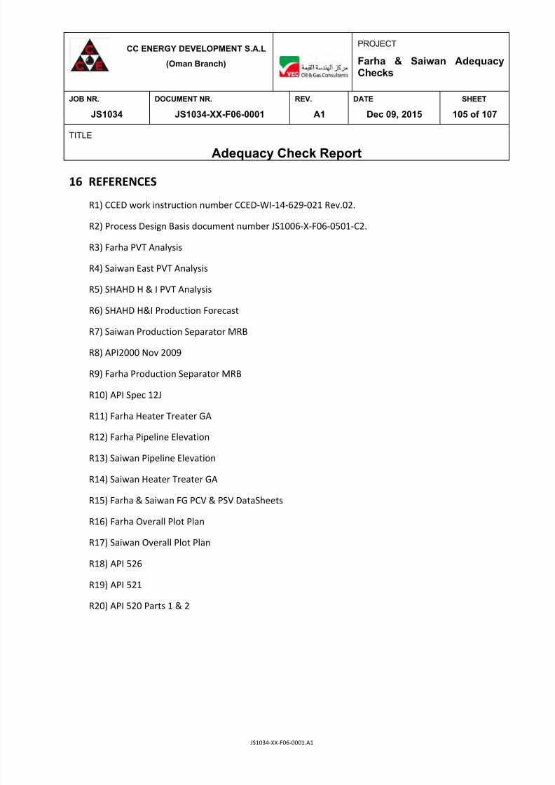
7/25/2019 JS1034-XX-F06-0001. A1
http://slidepdf.com/reader/full/js1034-xx-f06-0001-a1 105/107
CC ENERGY DEVELOPMENT S.A.L
(Oman Branch)
PROJECT
Farha & Saiwan AdequacyChecks
JOB NR. DOCUMENT NR. REV. DATE SHEET
JS1034 JS1034-XX-F06-0001 A1 Dec 09, 2015 105 of 107
TITLE
Adequacy Check Report
JS1034-XX-F06-0001.A1
16 REFERENCES
R1) CCED work instruction number CCED-WI-14-629-021 Rev.02.
R2) Process Design Basis document number JS1006-X-F06-0501-C2.
R3) Farha PVT Analysis
R4) Saiwan East PVT Analysis
R5) SHAHD H & I PVT Analysis
R6) SHAHD H&I Production Forecast
R7) Saiwan Production Separator MRB
R8) API2000 Nov 2009
R9) Farha Production Separator MRB
R10) API Spec 12J
R11) Farha Heater Treater GA
R12) Farha Pipeline Elevation
R13) Saiwan Pipeline Elevation
R14) Saiwan Heater Treater GA
R15) Farha & Saiwan FG PCV & PSV DataSheets
R16) Farha Overall Plot Plan
R17) Saiwan Overall Plot Plan
R18) API 526
R19) API 521
R20) API 520 Parts 1 & 2

7/25/2019 JS1034-XX-F06-0001. A1
http://slidepdf.com/reader/full/js1034-xx-f06-0001-a1 106/107
CC ENERGY DEVELOPMENT S.A.L
(Oman Branch)
PROJECT
Farha & Saiwan AdequacyChecks
JOB NR. DOCUMENT NR. REV. DATE SHEET
JS1034 JS1034-XX-F06-0001 A1 Dec 09, 2015 106 of 107
TITLE
Adequacy Check Report
JS1034-XX-F06-0001.A1
17 APPENDICES
A1) H&MB FARHA & Saiwan
A2) Farha Control Valves & SDV's
A3) Saiwan Control Valves & SDV's
A4) Blanket Calc 221-TA-001A
A5) Blanket Calc 220-TA-001A
A6) Farha PFD
A7) Saiwan PFD
A8) Farha Manifold Calculation
A9) Saiwan Manifold Calculation
A10) Operating Envelope Farha Separator
A11) Operating Envelope Farha Heater Treater
A12) Farha Booster and Export Pump Curves
A13) Operating Envelope Saiwan Separator Saiwan Crude
A14) Operating Envelope Saiwan Separator – SHAHD
A15) Operating Envelope for Saiwan Heater Treater
A16) Operating Envelope for Saiwan HT - SHAHD
A17) Saiwan Booster and Export Pump Curves
A18) Farha Crude Header Calculation
A19) Farha Produced Water Header Calculation
A20) Farha Produced Gas Header Calculation
A21) Saiwan Crude Header Calculation
A22) Saiwan Produced Water Header Calculation
A23) Saiwan Produced Gas Header Calculation
A24) Farha LP Flare Assesment Summary Tables incl RVs
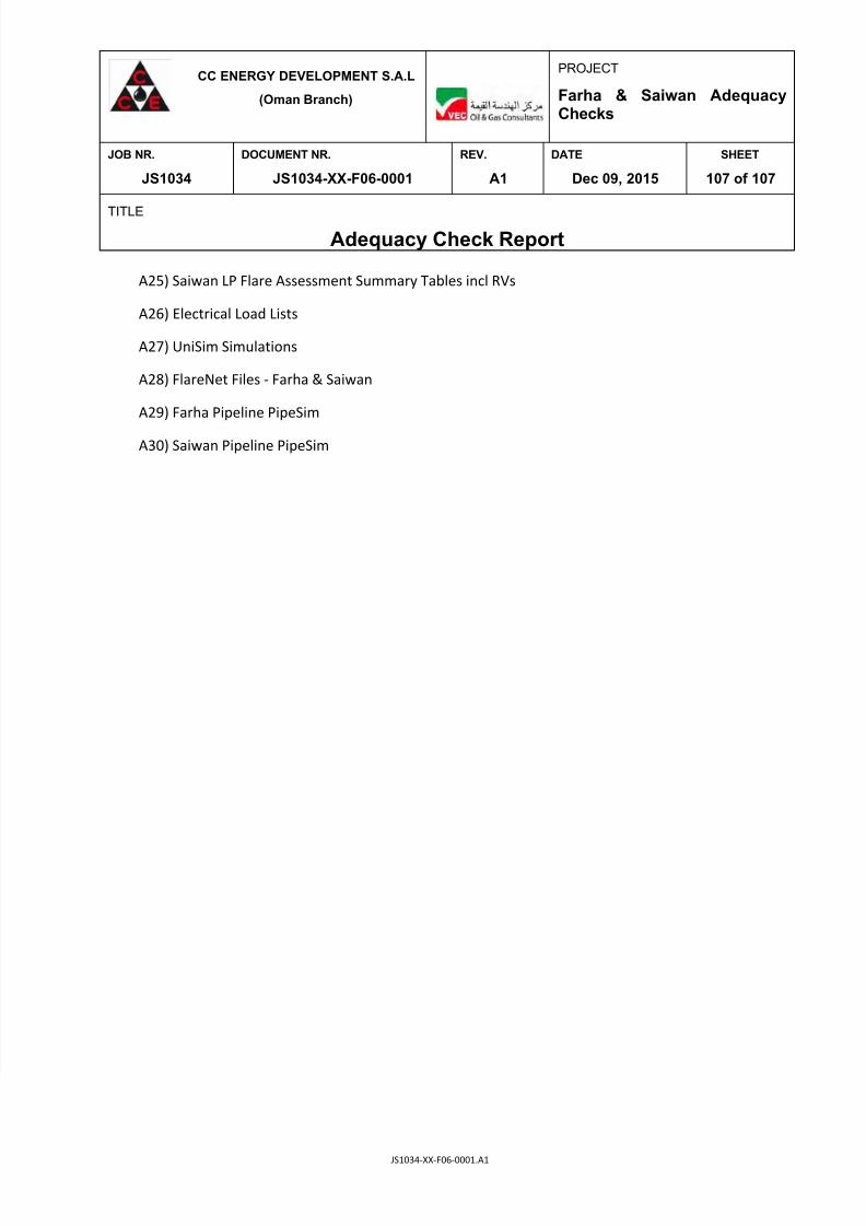
7/25/2019 JS1034-XX-F06-0001. A1
http://slidepdf.com/reader/full/js1034-xx-f06-0001-a1 107/107
CC ENERGY DEVELOPMENT S.A.L
(Oman Branch)
PROJECT
Farha & Saiwan AdequacyChecks
JOB NR. DOCUMENT NR. REV. DATE SHEET
JS1034 JS1034-XX-F06-0001 A1 Dec 09, 2015 107 of 107
TITLE
Adequacy Check Report
A25) Saiwan LP Flare Assessment Summary Tables incl RVs
A26) Electrical Load Lists
A27) UniSim Simulations
A28) FlareNet Files - Farha & Saiwan
A29) Farha Pipeline PipeSim
A30) Saiwan Pipeline PipeSim