Embed Size (px)
Citation preview
Transportation Technology Center, Inc., a subsidiary of the Association of American Railroads
27th Annual 2015 Quality Auditors and Industry Conference © TTCI/AAR, 1/10/2012. filename, p1
Joy Cooke
CSXT
Dennis Devanney
Winchester Industries,
Inc.
Mark Lumadue
Standard Steel, LLC
2:30 to 3:30 p.m.
Auditing Gage
Calibration
2
AAR M-1003 QA Requirements for
AUDITING GAUGE CALIBRATION
The purpose of this presentation is to explain various techniques that can be used to audit an AAR M-1003 Gauge Calibration program in accordance with the requirements specified in AAR Manual of Standards and Recommended Practices, Section J, Issue of 2014, Paragraphs 2.8 through 2.8.10. AAR Auditor’s Conference
Jacksonville, FL 2015
AAR Auditor’s Conference Jacksonville, FL 2015
3
BACKGROUND INFORMATION The AAR – Association of American Railroads – issues
the Manual of Standards and Recommended Practices. There are currently 28 manuals that specify requirements for design, fabrication, repair, reconditioning and maintenance of freight cars, locomotives, and their component parts.
Section J contains AAR Specification M-1003. It was originally adopted in 1985 as the Railroad Specification for Quality Assurance.
Freight car roller bearings and component parts were the original commodity governed by AAR M-1003.
Today there are more than 788 contractors manufacturing, assembling, or reconditioning more than 122 components governed by the AAR M-1003 Specification.
AAR Auditor’s Conference Jacksonville, FL 2015
4
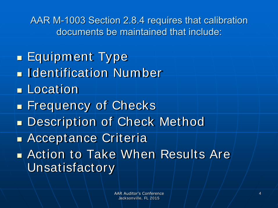
AAR M-1003 Section 2.8.4 requires that calibration documents be maintained that include:
Equipment Type
Identification Number
Location
Frequency of Checks
Description of Check Method
Acceptance Criteria
Action to Take When Results Are Unsatisfactory
AAR Auditor’s Conference Jacksonville, FL 2015
5
Documented Procedures
EXAMPLE
OF A
METHOD OF CALIBRATION
OR
CHECK METHOD
AAR Auditor’s Conference Jacksonville, FL 2015
6
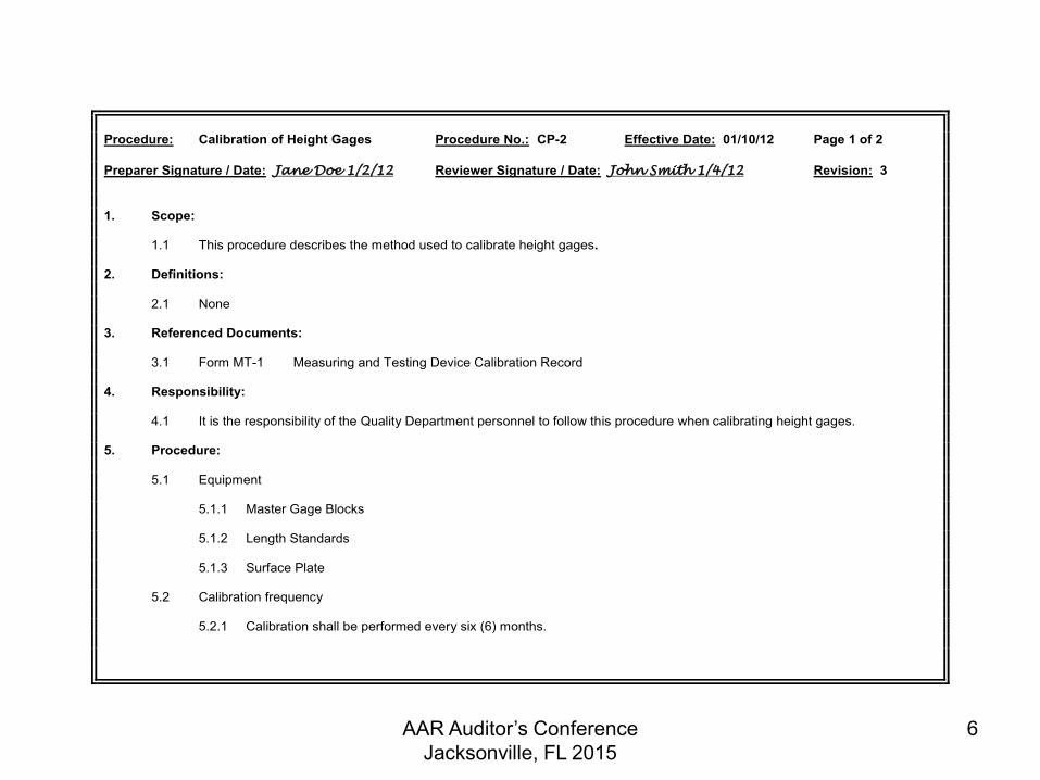
Procedure: Calibration of Height Gages Procedure No.: CP-2 Effective Date: 01/10/12 Page 1 of 2 Preparer Signature / Date: Jane Doe 1/2/12 Reviewer Signature / Date: John Smith 1/4/12 Revision: 3 1. Scope: 1.1 This procedure describes the method used to calibrate height gages. 2. Definitions: 2.1 None 3. Referenced Documents: 3.1 Form MT-1 Measuring and Testing Device Calibration Record 4. Responsibility: 4.1 It is the responsibility of the Quality Department personnel to follow this procedure when calibrating height gages. 5. Procedure: 5.1 Equipment 5.1.1 Master Gage Blocks 5.1.2 Length Standards 5.1.3 Surface Plate 5.2 Calibration frequency 5.2.1 Calibration shall be performed every six (6) months.
AAR Auditor’s Conference Jacksonville, FL 2015
7
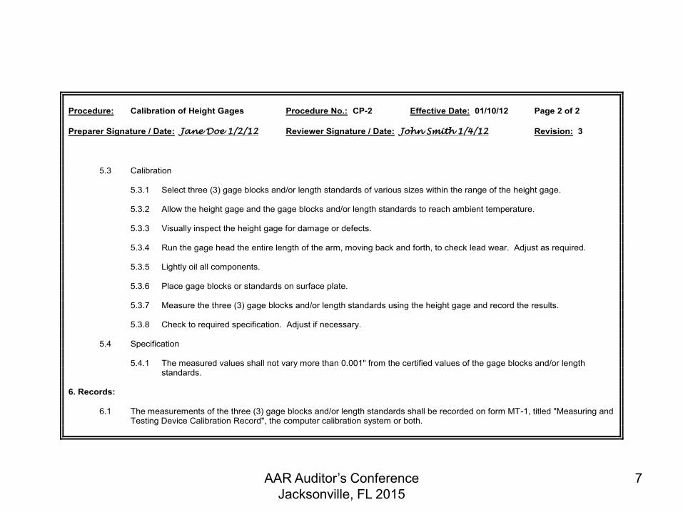
Procedure: Calibration of Height Gages Procedure No.: CP-2 Effective Date: 01/10/12 Page 2 of 2 Preparer Signature / Date: Jane Doe 1/2/12 Reviewer Signature / Date: John Smith 1/4/12 Revision: 3 5.3 Calibration 5.3.1 Select three (3) gage blocks and/or length standards of various sizes within the range of the height gage. 5.3.2 Allow the height gage and the gage blocks and/or length standards to reach ambient temperature. 5.3.3 Visually inspect the height gage for damage or defects. 5.3.4 Run the gage head the entire length of the arm, moving back and forth, to check lead wear. Adjust as required. 5.3.5 Lightly oil all components. 5.3.6 Place gage blocks or standards on surface plate. 5.3.7 Measure the three (3) gage blocks and/or length standards using the height gage and record the results. 5.3.8 Check to required specification. Adjust if necessary. 5.4 Specification 5.4.1 The measured values shall not vary more than 0.001" from the certified values of the gage blocks and/or length standards. 6. Records: 6.1 The measurements of the three (3) gage blocks and/or length standards shall be recorded on form MT-1, titled "Measuring and Testing Device Calibration Record", the computer calibration system or both.
AAR Auditor’s Conference Jacksonville, FL 2015
8
Calibration Status AAR M-1003 Section 2.8.5 requires that
measuring and test equipment be identified with a tag, sticker, or other suitable indicator to show the calibration status.
The purpose of the status indicator is to provide a clearly visible indicator to the user that the gage is in calibration or alert the user that the gage is due for calibration.
The type of indicator to be used is dependent on the type of gage and the environment where the gage is used.
The contractor determines the type of status indicators to be used.
AAR Auditor’s Conference Jacksonville, FL 2015
9
Calibration Status
Calibration Stickers
Commonly used and include the following:
Calibration / Certification – as the header
ID No. – the serial number of the gage
By – the person who performed the calibration
Date – the date of the calibration
Due – the date for the next required calibration

AAR Auditor’s Conference Jacksonville, FL 2015
10
Calibration Status
Calibration Stickers – Alternate Methods
Apply Sticker to Gage Storage Container – many small micrometers, dial indicators, calipers, etc. are stored in a box or container. Some facilities use gage storage boards. It is normally acceptable to apply the calibration sticker to the container. If several gages are stored on the same board, a sticker unique to each gage should be posted. It is important that each gage be permanently marked or etched with a unique serial number.
AAR Auditor’s Conference Jacksonville, FL 2015
11
Calibration Status Calibration Stickers – Alternate Methods
Color Coding – Gages can be color coded to indicate calibration status. The gage is painted or marked with a unique color. A calibration status instruction or board must be posted in the work area and must be readily accessible by the gage user.
Caution: - Calibration records are critical. With no date on the gage, the calibration record is the only objective evidence when the gage was calibrated.
Serial Number must be etched on the gage.
AAR Auditor’s Conference Jacksonville, FL 2015
12
Calibration Status
Calibration Stickers – Alternate Methods
Engraving / Stamping – Gages subjected to harsh environments that destroys stickers or paint codes can be engraved or stamped with a unique serial number and the calibration date.
Instructions or procedure for determining calibration due date must be posted or readily available for the gage user.
AAR Auditor’s Conference Jacksonville, FL 2015
13
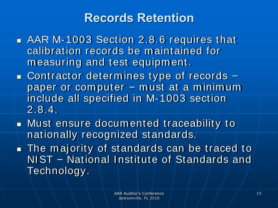
Records Retention AAR M-1003 Section 2.8.6 requires that
calibration records be maintained for measuring and test equipment.
Contractor determines type of records – paper or computer – must at a minimum include all specified in M-1003 section 2.8.4.
Must ensure documented traceability to nationally recognized standards.
The majority of standards can be traced to NIST – National Institute of Standards and Technology.

AAR Auditor’s Conference Jacksonville, FL 2015
14
Records Retention
TYPICAL NIST REFERENCE NUMBER
821 / 252343 – 14
Internal Year Lab # 6 Position of Test Traceability # (first character may be "alpha")
AAR Auditor’s Conference Jacksonville, FL 2015
15
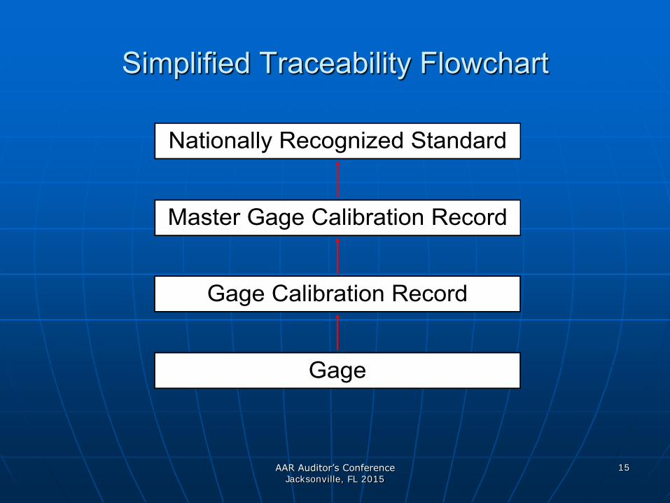
Simplified Traceability Flowchart
Nationally Recognized Standard
Master Gage Calibration Record
Gage Calibration Record
Gage
AAR Auditor’s Conference Jacksonville, FL 2015
16
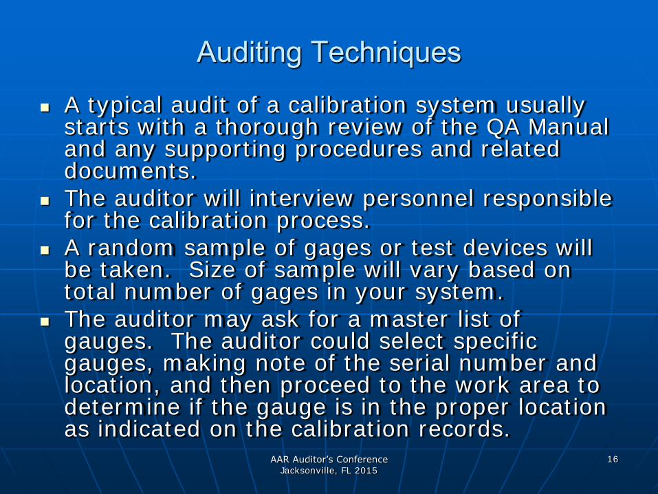
Auditing Techniques
A typical audit of a calibration system usually starts with a thorough review of the QA Manual and any supporting procedures and related documents.
The auditor will interview personnel responsible for the calibration process.
A random sample of gages or test devices will be taken. Size of sample will vary based on total number of gages in your system.
The auditor may ask for a master list of gauges. The auditor could select specific gauges, making note of the serial number and location, and then proceed to the work area to determine if the gauge is in the proper location as indicated on the calibration records.

AAR Auditor’s Conference Jacksonville, FL 2015
17
WHEEL, WHEEL BEARING, SIDE FRAME & SIDE FRAME PARTS GAUGES
PG # GAGE I.D. CAL. DUE GANG GAGE LOC. STATUS DESCRIPTION
MODEL #
7 022496-2 SENT BACK TO BACK MOUNTING GAGE N/A
8 100900-1 9/2/2015 TRUCK TRACK
1/2 BACK TO BACK MOUNTING GAGE N/A
9 072096-4 STORAG
E SIMPLIFIED WHEEL GAGE RP-615-77
12 112200-37 3/11/2015 TRUCK TRACK
2 SIMPLIFIED WHEEL GAGE RP-615-77
Master List of Project Shop Gages REVISED 9/3/2014
AAR Auditor’s Conference Jacksonville, FL 2015
18
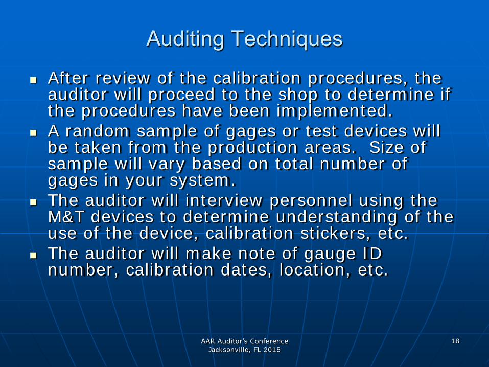
Auditing Techniques
After review of the calibration procedures, the auditor will proceed to the shop to determine if the procedures have been implemented.
A random sample of gages or test devices will be taken from the production areas. Size of sample will vary based on total number of gages in your system.
The auditor will interview personnel using the M&T devices to determine understanding of the use of the device, calibration stickers, etc.
The auditor will make note of gauge ID number, calibration dates, location, etc.

AAR Auditor’s Conference Jacksonville, FL 2015
19
Typical Audit of Traceability
The auditor will ask to review the calibration records for the specific gauges sampled during the tour of the facility.
Records must be readily available, and may be on-line, or hard copy.
We will now audit a typical gage to ensure the proper documentation exists to provide traceability to nationally recognized standards.

AAR Auditor’s Conference Jacksonville, FL 2015
20
Typical Audit of Traceability
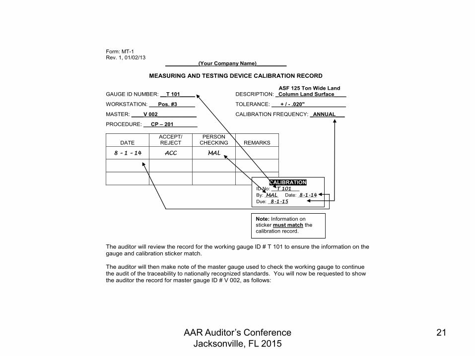
The auditor will make note of the gage description, serial (ID) number, workstation, and calibration dates. You will be required to show the documented record trail from the gage to nationally recognized standards as follows:
T101 1-8987 COLUMN LAND SURFACE GAUGE
ASF 125 TON WIDE LAND GR. C RIDE CONTROL
Engraved
CALIBRATION ID No:____T 101________ By: _MAL_ Date:_8-1-14_ Due: __8-1-15__________
AAR Auditor’s Conference Jacksonville, FL 2015
21
Form: MT-1 Rev. 1, 01/02/13 ___________(Your Company Name)__________
MEASURING AND TESTING DEVICE CALIBRATION RECORD ASF 125 Ton Wide Land GAUGE ID NUMBER: __T 101_____ DESCRIPTION: _Column Land Surface____ WORKSTATION: Pos. #3 TOLERANCE: + / - .020" MASTER: ____V 002_____________ CALIBRATION FREQUENCY: _ANNUAL___ PROCEDURE: CP – 201
DATE
ACCEPT/ REJECT
PERSON CHECKING
REMARKS
8 – 1 – 14 ACC MAL
The auditor will review the record for the working gauge ID # T 101 to ensure the information on the gauge and calibration sticker match. The auditor will then make note of the master gauge used to check the working gauge to continue the audit of the traceability to nationally recognized standards. You will now be requested to show the auditor the record for master gauge ID # V 002, as follows:
CALIBRATION ID No: T 101 By: MAL Date: 8-1-14 Due: 8-1-15
Note: Information on sticker must match the calibration record.

AAR Auditor’s Conference Jacksonville, FL 2015
22
Form: MT-1 Rev. 1, 01/02/13 ___________(Your Company Name)__________
MEASURING AND TESTING DEVICE CALIBRATION RECORD GAUGE ID NUMBER: __V 002_____ DESCRIPTION: 24" Vernier Caliper ___ WORKSTATION: Gauge Room TOLERANCE: + / - .0005" MASTER: Gauge Room Set – GB1_ CALIBRATION FREQUENCY: _6 Month ___ PROCEDURE: CP – 101
DATE
ACCEPT/ REJECT
PERSON CHECKING
REMARKS
1– 23 – 14 ACC MAL
Used Blocks
2, 4, 6, 12"
7– 23 – 14 ACC MAL Used Blocks
2, 4, 6, 12"
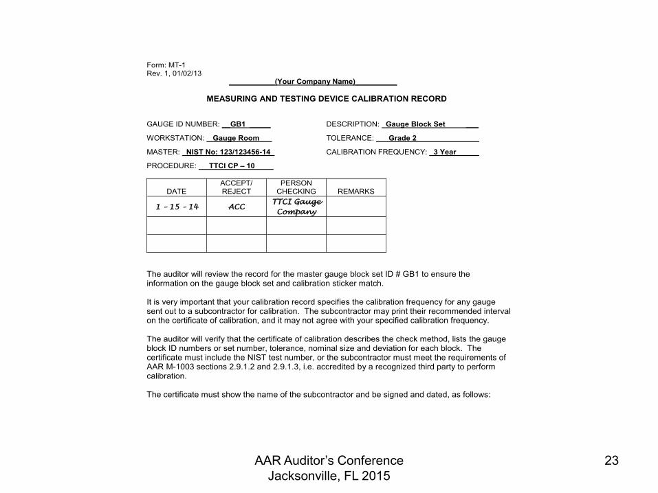
The auditor will review the record for the master gauge ID # V 002 to ensure the information on the gauge and calibration sticker match. The auditor will make note of the master gauge used to check gauge ID # V 002 to continue the audit of the traceability to nationally recognized standards. The record for master gauge block set ID # GB1, follows:
Note: Record the actual gauge blocks used from a set of blocks. When the set ID, such as "GB1" is etched on the individual blocks, it is normally acceptable to record only the size of block used. You will need to record the ID number for each block when the set ID is not on the individual blocks, or when a block within a set has been replaced.
AAR Auditor’s Conference Jacksonville, FL 2015
23
Form: MT-1 Rev. 1, 01/02/13 ___________(Your Company Name)__________
MEASURING AND TESTING DEVICE CALIBRATION RECORD GAUGE ID NUMBER: __GB1 _____ DESCRIPTION: Gauge Block Set ___ WORKSTATION: Gauge Room TOLERANCE: Grade 2 MASTER: NIST No: 123/123456-14_ CALIBRATION FREQUENCY: _3 Year ___ PROCEDURE: TTCI CP – 10
DATE
ACCEPT/ REJECT
PERSON CHECKING
REMARKS
1 – 15 – 14 ACC
TTCI Gauge
Company
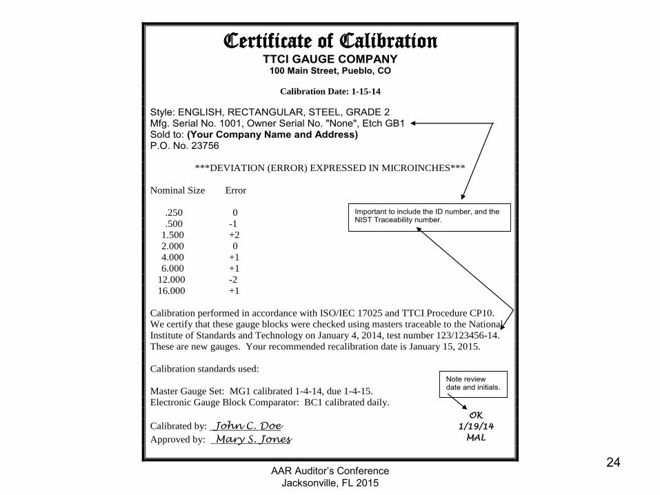
The auditor will review the record for the master gauge block set ID # GB1 to ensure the information on the gauge block set and calibration sticker match. It is very important that your calibration record specifies the calibration frequency for any gauge sent out to a subcontractor for calibration. The subcontractor may print their recommended interval on the certificate of calibration, and it may not agree with your specified calibration frequency. The auditor will verify that the certificate of calibration describes the check method, lists the gauge block ID numbers or set number, tolerance, nominal size and deviation for each block. The certificate must include the NIST test number, or the subcontractor must meet the requirements of AAR M-1003 sections 2.9.1.2 and 2.9.1.3, i.e. accredited by a recognized third party to perform calibration. The certificate must show the name of the subcontractor and be signed and dated, as follows:
AAR Auditor’s Conference Jacksonville, FL 2015
24
Certificate of Calibration TTCI GAUGE COMPANY
100 Main Street, Pueblo, CO
Calibration Date: 1-15-14
Style: ENGLISH, RECTANGULAR, STEEL, GRADE 2 Mfg. Serial No. 1001, Owner Serial No. "None", Etch GB1 Sold to: (Your Company Name and Address) P.O. No. 23756
***DEVIATION (ERROR) EXPRESSED IN MICROINCHES***
Nominal Size Error
.250 0
.500 -1
1.500 +2
2.000 0
4.000 +1
6.000 +1
12.000 -2
16.000 +1
Calibration performed in accordance with ISO/IEC 17025 and TTCI Procedure CP10.
We certify that these gauge blocks were checked using masters traceable to the National
Institute of Standards and Technology on January 4, 2014, test number 123/123456-14.
These are new gauges. Your recommended recalibration date is January 15, 2015.
Calibration standards used:
Master Gauge Set: MG1 calibrated 1-4-14, due 1-4-15.
Electronic Gauge Block Comparator: BC1 calibrated daily.
Calibrated by: John C. Doe
Approved by: Mary S. Jones
OK
1/19/14
MAL
Important to include the ID number, and the NIST Traceability number.
Note review date and initials.
AAR Auditor’s Conference Jacksonville, FL 2015
25
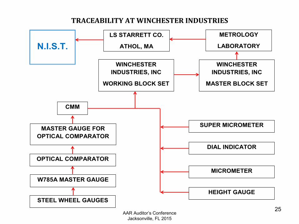
TRACEABILITY AT WINCHESTER INDUSTRIES
N.I.S.T. LS STARRETT CO.
ATHOL, MA
METROLOGY
LABORATORY
WINCHESTER INDUSTRIES, INC
MASTER BLOCK SET
WINCHESTER INDUSTRIES, INC
WORKING BLOCK SET
CMM
MASTER GAUGE FOR OPTICAL COMPARATOR
OPTICAL COMPARATOR
W785A MASTER GAUGE
STEEL WHEEL GAUGES
SUPER MICROMETER
DIAL INDICATOR
MICROMETER
HEIGHT GAUGE
AAR Auditor’s Conference Jacksonville, FL 2015
26
Method of Verification
A verification procedure is required and must specify the verification process for a specific method. Appropriate methods include:
Certified Metrology Lab Verification Contour Mapping Master Gauges Go – No Go Gauges Toleranced Dimension Verification Measurements using Certified Test Equipment
AAR Auditor’s Conference Jacksonville, FL 2015
27
Reference Authority
The recognized organization responsible for issuing and maintaining the specification used to verify the measuring and test equipment. Example include:
Manufacturers of M & T equipment (OEM) Government Agencies Trade Organizations ANSI
AAR Auditor’s Conference Jacksonville, FL 2015
28
Reference Specification
The detailed definition used as the basis for verification. Usually dependent on a reference authority. Example include:
Product Specifications Manufacturers drawings Trade Standards ANSI Specifications Quality Program Specifications Winchester Industries, Inc. drawings
AAR Auditor’s Conference Jacksonville, FL 2015
29
Non-Conforming Gauges
Measuring and Test Equipment is designed to properly verify product throughout it’s entire life cycle.
It is normal to expect M & T Equipment to eventually fail at time of re-certification.
NORMAL FAILURE occurs when equipment “eases” out of the tolerance range due to normal use. Equipment is typically designed to reach this condition without affecting the product verification process.
GROSS FAILURE occurs when a device fails prematurely and affects product quality. An ASSESSMENT of affected product must be performed.
AAR Auditor’s Conference Jacksonville, FL 2015
30
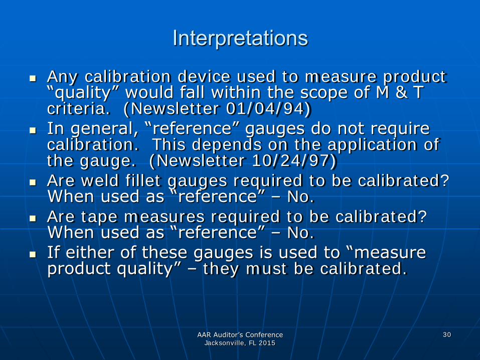
Interpretations
Any calibration device used to measure product “quality” would fall within the scope of M & T criteria. (Newsletter 01/04/94)
In general, “reference” gauges do not require calibration. This depends on the application of the gauge. (Newsletter 10/24/97)
Are weld fillet gauges required to be calibrated? When used as “reference” – No.
Are tape measures required to be calibrated? When used as “reference” – No.
If either of these gauges is used to “measure product quality” – they must be calibrated.
AAR Auditor’s Conference Jacksonville, FL 2015
31
Questions ?
AAR M-1003 QA Requirements for
AUDITING GAUGE CALIBRATION