Embed Size (px)
Citation preview
JOURNAL OF MICROELECTROMECHANICAL SYSTEMS, VOL. 26, NO. 1, FEBRUARY 2017 215
On-Chip Dynamic Mode Atomic Force Microscopy:A Silicon-on-Insulator MEMS Approach
Michael G. Ruppert, Student Member, IEEE, Anthony G. Fowler, Member, IEEE,Mohammad Maroufi, Member, IEEE, and S. O. Reza Moheimani, Fellow, IEEE
Abstract— The atomic force microscope (AFM) is an invaluablescientific tool; however, its conventional implementation as arelatively costly macroscale system is a barrier to its morewidespread use. A microelectromechanical systems (MEMS)approach to AFM design has the potential to significantly reducethe cost and complexity of the AFM, expanding its utility beyondcurrent applications. This paper presents an on-chip AFM basedon a silicon-on-insulator MEMS fabrication process. The devicefeatures integrated xy electrostatic actuators and electrothermalsensors as well as an AlN piezoelectric layer for out-of-planeactuation and integrated deflection sensing of a microcantilever.The three-degree-of-freedom design allows the probe scanner toobtain topographic tapping-mode AFM images with an imagingrange of up to 8µm × 8µm in closed loop. [2016-0211]
Index Terms— Atomic force microscope, piezoelectric self-sensing, electrothermal sensing, electrostatic actuation, micro-electromechanical systems (MEMS).
I. INTRODUCTION
FOR several decades, the atomic force microscope (AFM)has remained one of the primary instruments used for
nanoscale object and material analysis in both research andindustrial applications. At the heart of the AFM is a micro-cantilever with a sharp probe tip, which is scanned over thesurface of a sample. By mapping the intermolecular forcesthat exist between the probe tip and the surface of the sample,the instrument is able to obtain the sample’s topography andmaterial properties with nanometer-scale resolution.
Since its introduction in the late 1980s [1], the AFM hasgenerally been implemented as a macroscale system, withthe instrument itself being many orders of magnitude largerthan the size of the scan window. Conventionally, the in-planescanning of the microcantilever is performed using piezoelec-tric tube scanners or flexure-guided nanopositioners, while thedeflection of the microcantilever is measured using a laserand a position sensitive detector [2], [3]. While commercial
Manuscript received August 30, 2016; revised October 19, 2016; acceptedOctober 29, 2016. Date of publication December 6, 2016; date of currentversion February 1, 2017. Subject Editor A. Zhang. (Corresponding author:S. O. Reza Moheimani.)
M. G. Ruppert is with the School of Electrical Engineering and ComputerScience, The University of Newcastle, Callaghan, NSW 2308, Australia(e-mail: [email protected]).
A. G. Fowler, M. Maroufi, and S. O. R. Moheimani are with theDepartment of Mechanical Engineering, University of Texas at Dallas,Richardson, TX 75080 USA (e-mail: [email protected];[email protected]; [email protected]).
This paper has supplementary downloadable material available athttp://ieeexplore.ieee.org., provided by the author.
Color versions of one or more of the figures in this paper are availableonline at http://ieeexplore.ieee.org.
Digital Object Identifier 10.1109/JMEMS.2016.2628890
AFMs are often able to perform high-speed scanning withsub-nanometer resolution, their high cost of acquisition andthe relative size of the hardware setup generally restricts theiruse to specialized laboratory-based applications.
More recently, microelecromechanical systems (MEMS)-based devices have emerged as a means of generatingmechanical displacements with nanoscale precision in a muchsmaller form factor than that of conventional macroscalenanopositioners [4]–[6]. In addition, a MEMS implementationprovides several other significant advantages, including muchlower costs of fabrication, batch manufacturability, and poten-tially increased operating bandwidths [7], [8]. Given thesepotential benefits, we have previously explored the use ofMEMS nanopositioners for AFM through the demonstrationof silicon-on-insulator (SOI)-based devices as an AFM’s scan-ning stage [9]–[12]. In [13], an in-plane MEMS nanopositionerwith two degrees of freedom (DOF) was presented, whichfeatures electrostatic actuators and electrothermal sensors. Thefirst resonance mode of the device along each axis is locatedat approximately 850 Hz, which enabled imaging in closedloop using a raster scan method with a maximum frequencyof 100 Hz. However, the relatively low bandwidth of thedevice limits the maximum achievable imaging frequency.As such, a high-bandwidth 2-DOF MEMS nanopositionerwas presented in [14] with more than 4.4 kHz bandwidthalong each axis. AFM imaging of the device was performedusing the raster scan method at 800 Hz in a window size of8µm × 8µm. Non-raster trajectories such as Lissajous andspiral methods were also implemented for a novel MEMSnanopositioner in [10] and [15] respectively to achieve fastin-plane scans. Using these methods, much higher scanfrequencies of 1000 Hz for the Lissajous method and 1430 Hzfor spiral scanning were demonstrated.
Having successfully miniaturized one of the primary subsys-tems of the AFM, the next logical step is the development of acomplete MEMS-based AFM. It is possible that the significantcost and portability improvements that may be achieved withthe introduction of such a device may allow the AFM to movebeyond its current role as a specialized scientific instrument.
In the literature, a single-chip AFM has been demonstratedthat uses a CMOS-MEMS fabrication process [16], [17].While the device has undergone a number of design iterations,it maintains the use of lateral and vertical electrothermalactuators to position a cantilever. The device is designed tooperate in tapping mode, with the amplitude of the resonantlyexcited cantilever’s oscillation being measured through the use
1057-7157 © 2016 IEEE. Personal use is permitted, but republication/redistribution requires IEEE permission.See http://www.ieee.org/publications_standards/publications/rights/index.html for more information.

216 JOURNAL OF MICROELECTROMECHANICAL SYSTEMS, VOL. 26, NO. 1, FEBRUARY 2017
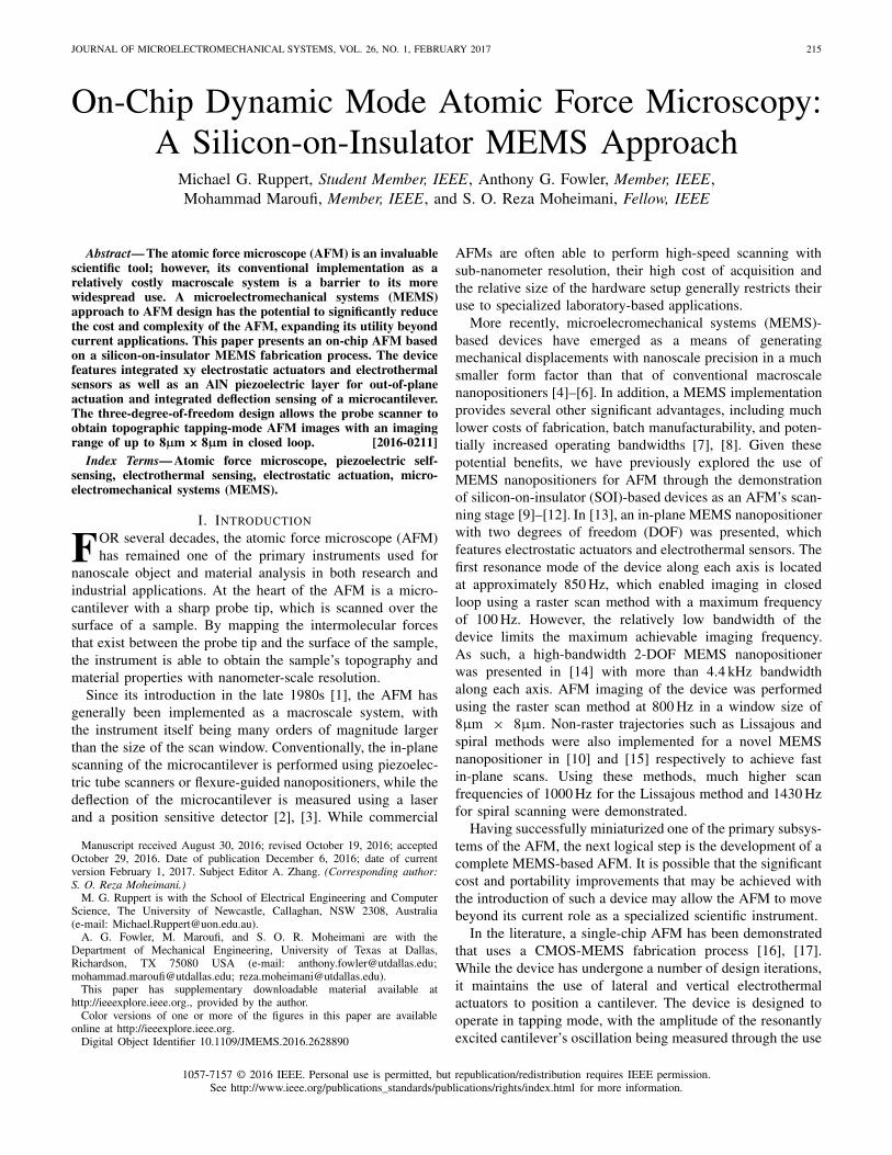
Fig. 1. The fabricated MEMS probe scanner, with close-up SEM images highlighting major components of the device. A serpentine structure for signal routingand an electrothermal sensor are shown in top-left and bottom-left close-up views, respectively. The close-up view in the top-right shows the cantilever andpiezoelectric actuators. The bottom-right image shows the tethering and shuttle beams for the x and y axes, folded flexures along the y axis, and electrostaticactuators. The top close-up images show the FIB deposited tip on the cantilever for AFM imaging.
of piezoresistive sensing. The authors have successfully usedthe device to obtain topographical images of various samples,demonstrating the feasibility of a microfabricated AFM.However, the use of electrothermal actuation mechanismspotentially places a number of limitations on the performanceof the device. Specifically, the operating bandwidth of elec-trothermal actuators is limited by their thermal mass and theirrate of heat dissipation, therefore restricting the ultimate scanrate achievable by the AFM [18], [19]. In addition, electrother-mal actuators use significantly more electrical power than otherforms of MEMS actuators [20]. While power consumptionmay not be a major consideration for a standalone device,it may become an issue if attempts are made to increase theeffective scan throughput by implementing multiple deviceswithin an array.
Integrated cantilever actuation and sensing are paramountas the traditionally employed piezo stack actuator at thebase of the cantilever and the optical beam deflection (OBD)method [21] are not compatible with the idea of a single-chip AFM. Furthermore, some of the integrated actuationmethods found in the literature such as magnetic [22],photothermal [23], or ultrasonic [24] still require externalequipment. As such, resistive thermal actuation [25] or viaa piezoelectric layer [26] and integrated sensing method-ologies such as capacitive [27], piezoresistive [28], andpiezoelectric [29] sensing are fully compatible with an on-chipsolution. Among these methods, piezoelectric transductionseems to be the only one capable of simultaneously serving asan actuator and a sensor even with a single active layer [30]which was therefore chosen for this work.
In [31], we introduced a microfabricated probe scanner,which demonstrated a novel SOI-MEMS approach to
designing an on-chip AFM. The device used electrostaticcomb-finger actuators to laterally position a stage containingan integrated silicon cantilever. Using a dedicated piezoelectricactuator, the cantilever was driven at its out-of-plane vibra-tional mode at 62 kHz, however no AFM images were able tobe obtained with the device as it did not possess a probe tip.
This paper presents a redesigned MEMS probe scanner thatis again fabricated using a SOI-MEMS fabrication process.The device features a central stage that is positioned alongthe x and y axes using electrostatic actuators, with integratedelectrothermal displacement sensors being implemented tofacilitate closed-loop position control of the stage. A siliconmicrocantilever designed for tapping-mode AFM is fabricatedat one end of the stage, and is actuated in the out-of-planedirection using a piezoelectric transducer made from a thinlayer of aluminum nitride (AlN). Using a high-side chargesensing implementation motivated by previous work [32], thesame piezoelectric transducer is also used to simultaneouslymeasure the deflection of the cantilever. Following the additionof a probe tip to the end of the cantilever, the probe scanneris successfully used to perform AFM scans of features on acalibration grating.
II. PROBE SCANNER DESIGN AND FABRICATION
A. Mechanical Design
A scanning electron microscope (SEM) image of the MEMSprobe scanner is shown in Fig. 1. The probe scanner isimplemented using the standard SOI-based PiezoMUMPs fab-rication process provided by MEMSCAP [33]. The thicknessof the device layer, from which the entire structure is obtained,is 10 µm.

RUPPERT et al.: ON-CHIP DYNAMIC MODE ATOMIC FORCE MICROSCOPY: A SILICON-ON-INSULATOR 217
Fig. 2. Finite element model simulation of the mode shapes of the fundamental mode of the (a) x axis, (b) y axis, and (c) cantilever out-of-planemode at 172 kHz.
At the center of the device is a stage with dimensionsof 2315 µm × 650 µm, while a two-section microcantileveris fabricated at the upper edge of the stage. The in-planedisplacement of the stage is obtained using a parallel kinematicmechanism. Along the device’s x axis, electrostatic actuatorsare implemented on both sides of the stage, enabling itto have a bidirectional displacement range. An electrostaticactuator is also implemented on one side of the stage alongthe y axis, resulting in unidirectional displacement in thisdirection. As is visible in the close-up view in Fig. 1, theactuators are connected to the stage via shuttle beams andtethering beams in both directions. Two sets of electrostaticactuators are implemented along the x axis to obtain higherforce while mitigating potential in-plane rotation of the stage.
As the y axis has a relatively large unidirectionaldisplacement range, using standard clamped-clamped beams asmechanical flexures can lead to the stage possessing a nonlin-ear force-displacement behavior. In [12], folded beam flexuresare proposed that provide in-plane stiffness with negligiblenonlinearity compared to clamped-clamped beams. We haveexploited this characteristic by designing the y-axis flexures ina similar manner. As the stage has a bidirectional displacementrange along the x axis, clamped-clamped beams can be used inthis direction as their stiffness can be considered to be linearwithin the displacement range of interest. In addition, thesebeams have a smaller form factor compared to the foldedflexures, leading to a more compact structure in this direction.The incorporated mechanical suspension systems in both axesare designed to prevent the occurrence of snap-in withinthe electrostatic actuators by providing sufficient longitudinalstiffness throughout the entire range of displacement andactuation voltages [11].
The implemented microcantilever has two sections, withthe wider section having dimensions of 380 µm × 240 µmand the narrower part being 260 µm × 40 µm. In order tooscillate the cantilever and simultaneously measure its vibra-tion amplitude, an AlN piezoelectric layer with a thicknessof 0.5 µm is deposited on the wider section of the micro-cantilever. The signal routing for the piezoelectric layer andthe electrical ground connections to the stage is performedusing long beams with dimensions of 2.3 mm × 25 µm and2.3 mm × 10 µm, respectively. The width of these beamsare minimized while considering the restrictions imposed by
the microfabrication process. Serpentine structures are alsoimplemented at the anchor points of these beams to reducetheir in-plane stiffness along the y direction.
During the design, the finite element model (FEM) of theprobe scanner is constructed in CoventorWare to investigateits mechanical characteristics. The results of the FEM modalanalysis are presented in Fig. 2. The device is designedsuch that its first two in-plane resonant modes are along thex and y axis as shown in Fig. 2(a) and (b), respectively.A resonance frequency of about 2.9 kHz is predicted for bothaxes, matching well with the experimental results shown inFig. 4. In Fig. 2(c), a high-frequency (172 kHz) mode shapeof the device is shown, which, due its large displacementand negligible induced motion in the rest of the device,is designed to be suitable for tapping-mode AFM imaging(compare experimental results in Section III and Fig. 5).
Electrothermal sensors are implemented for both axes tomeasure the in-plane motion of the stage. As is shown in aclose-up view in Fig. 1, the sensor comprises two heaters inproximity to a heat sink, which is implemented as a part ofeach shuttle beam [34]. As the heat sink moves parallel to theheaters, the rate of heat transfer between the heaters and theheat sink changes. This leads to opposing variations in theirtemperature, and as a result, changes in the electrical resistanceof the heaters. A transimpedance circuit (shown in more detailin [14]) is used to translate the electrical resistance changesof the heaters to a varying output voltage.
B. AFM Tip
A sharp tip was added to the fabricated probe scanner usinga focused ion beam (FIB) system (FEI Nova NanoLab 200),allowing the device to be used to image a sample viatapping-mode AFM. This method of AFM tip fabricationhas been utilized in both commercial cantilever produc-tion and research applications, and is capable of producinghigh-resolution, high-aspect-ratio tips [35]. Using ion beamdeposition of platinum, a stepped support structure with atotal height of approximately 9 µm was first constructed at theend of the probe scanner’s cantilever. A thin platinum needlewas then deposited at the top of the support structure usingelectron beam deposition, yielding a tip 1.5 µm in length andwith a diameter of approximately 40 nm. SEM images of thedeposited probe tip are shown in Fig. 1.

218 JOURNAL OF MICROELECTROMECHANICAL SYSTEMS, VOL. 26, NO. 1, FEBRUARY 2017
Fig. 3. In-plane displacement and corresponding electrothermal sensor outputvs. actuation voltage for the probe scanner’s x and y axes.
While the use of an FIB system for tip fabrication issufficient to demonstrate the operation of the probe scanner,a MEMS microfabricated tip is ultimately required to enablethe cost-effective batch fabrication of the device. This ispossible through techniques such as KOH wet etching orisotropic reactive ion etching [36], [37], which are currentlybeing evaluated to enable the complete batch fabrication offuture versions of the probe scanner.
III. XY-NANOPOSITIONER CHARACTERIZATION
AND CONTROL
The characterization of the fabricated system is performedwhile the electrothermal sensors are active with a 5 V biasvoltage. As the electrostatic actuators along the x axis areimplemented on both sides of the stage, a linear actuationmechanism can be implemented for this axis [14]. With thismechanism, the actuation signal is applied to the electro-static actuators with opposite polarities while superimposedon a DC bias voltage, which is adjusted to be 35 V inour experiments. This mechanism can drastically alleviatethe well-understood quadratic behavior of the electrostaticactuators [14].
The in-plane mechanism of the device is characterized inboth the time and frequency domains. A low frequency trian-gular signal is applied to both axes, while their displacementsare measured using a Polytec MSA-100-3D Micro SystemAnalyzer (MSA). In Fig. 3, the in-plane displacement forboth axes is shown as a function of the actuation signal. Thedisplacement along the x axis slightly deviates from linearas shown in Fig. 3a. This can be attributed to nonlinearitiesin the stiffness of the clamped-clamped beams and possibleasymmetry in the structure of the comb drive actuators.
TABLE I
THE CALIBRATION FACTORS AND RESOLUTION OF THE
ELECTROTHERMAL SENSORS FOR X AND Y AXES
Fig. 4. The frequency response of the probe scanner along the x and y axes.For the sake of clarity, the DC gains are adjusted to unity.
The quadratic behavior of the y axis is also visible inFig. 3b. A displacement range of more than 10 µm is obtainedfor both axes. The outputs of the electrothermal sensors aresimultaneously recorded and are presented in the same figurefor both axes. Each sensor’s output is a linear function of thecorresponding axis displacement, with the resulting calibrationfactors for the sensors being reported in Table I.
The frequency response of the in-plane mechanical structureis obtained for both axes using the MSA, and is shownin Fig. 4. As is visible, the first resonant modes alongthe x and y axes are located at 2.85 kHz and 2.77 kHz,respectively.
The out-of-plane vibration of the microcantilever is alsocharacterized in the frequency domain by applying a wide-band periodic chirp as an actuation signal to its piezoelectrictransducer. During this test, the MSA is used to obtain thevarious out-of-plane mode shapes of the probe scanner bymeasuring the mechanical response of the device at a largenumber of points across its moving structure. The objectiveis to determine a mode shape within which the cantilever hasa large enough oscillation amplitude to be used for tapping-mode AFM imaging while other parts of the device shownegligible displacement. The experimental test shows that thiscriteria is best satisfied at the mode located at approximately200 kHz, with Fig. 5 showing the vibration of the probescanner at this mode.
To obtain the resolution of the electrothermal sensors, theiroutput noise is characterized in the time-domain. The noise isrecorded with a sampling frequency of 781 kHz over a timeperiod of 12.8 s. A fourth-order anti-aliasing low-pass filterwith a cut-off frequency of 100 kHz is employed by seriesconnecting two Stanford Research SR560 low-noise voltagepreamplifiers. The resolution of the sensors is reported inTable I, and is calculated by converting the root meansquare (rms) value of the sensors’ output noise to thecorresponding displacement using their previously obtainedcalibration factors.

RUPPERT et al.: ON-CHIP DYNAMIC MODE ATOMIC FORCE MICROSCOPY: A SILICON-ON-INSULATOR 219
Fig. 5. The shape of the probe scanner’s flexural mode used forAFM imaging, measured experimentally using the MSA.
IV. CANTILEVER CHARACTERIZATION AND CONTROL
A. System Model
Assuming perfect bonding between the piezoelectrictransducer and the cantilever beam and a clamped boundarycondition at the base of the cantilever, a voltage applied to theelectrodes results in a bending moment causing the cantileverto deflect. The transfer function from actuation voltage V (s)to tip displacement D(s) of the piezoelectric cantilever, canbe described by a sum of n second order modes [38]
Gdv (s) = D(s)
V (s)=
n∑
i=1
αiω2i
s2 + ωiQi
s + ω2i
, (1)
where each second order term is associated with a specificvibrational mode shape and is characterized in terms of therespective resonance frequency ωi , quality factor Qi , andgain αi . Similarly, when the piezoelectric transducer is sub-jected to mechanical strain, it becomes electrically polarized,producing a charge on the surface of the material. Neglectingparasitic effects, this direct piezoelectric effect can be modeledas a strain dependent voltage source Vp(s) in series withthe piezoelectric capacitance Cp , describing the dielectricproperties of the material [30]. The model is a simplifiedversion of the Butterworth Van Dyke model as proposed bythe IEEE Standard on Piezoelectricity [39]. For this simplifiedcase, the transfer function from actuation voltage to chargeQ(s) can be found to be [40]
Gqv (s) = Q(s)
V (s)= Cp + Cp
n∑
i=1
Gvv,i(s) (2)
where
Gvv(s) = Vp(s)
V (s)=
n∑
i=1
βiω2i
s2 + ωiQi
s + ω2i
(3)
is the transfer function from actuation voltage to piezoelectricstrain voltage [41]. Observing that each mode in Gdv andGvv only differ by a constant factor, (2) can be rewritten toyield
Gqv (s) = Q(s)
V (s)= Cp + Cp
n∑
i=1
γi Gdv,i(s). (4)
Fig. 6. (a) Electrical circuit model of the piezoelectric cantilever impedancewith series parasitic resistance due to the silicon ground trace. (b) Frequencyresponse of the complex impedance of the piezoelectric cantilever measuredwith an impedance analyzer (blue) and model (5) (red).
TABLE II
IMPEDANCE MODEL PARAMETERS
From (4) it can be seen that a deflection estimate can beobtained by measuring the charge on the piezoelectric layerwhile the cantilever is being actively driven by a voltage sourceif the feedthrough CpV (s) can be canceled.
B. Piezoelectric Impedance
For this work, the above equivalent model is not sufficient todescribe the electrical properties of the MEMS probe scanner.As such, it had to be amended by an additional parallelresistance Rp to take into account dielectric losses as well asa series resistance Rs which models the parasitic arising fromthe doped silicon ground trace. The equivalent electrical modelof the piezoelectric layer is shown in the circuit diagram inFig. 6(a). The resulting impedance Z(s) can be calculated as
Z(s) = Rp||Cp + Rs
= RsCp Rps + Rp + Rs
Cp Rps + 1. (5)
To validate the model, the complex impedance (|Z | indB�, � Z in deg) is measured with an impedance analyzer(Keysight, 4990A) and plotted in Fig. 6(b) and compared withthe model (5). It can be seen that the extra zero caused by theseries resistance Rs adequately describes the phase increasein the frequency range from 10 kHz to 1 MHz. The parallelresistance Rp creates a pole at low frequencies and does notcontribute significantly to the behavior of Z(s). Solving forthe individual terms of the model (5) based on the identifiedmodel of the impedance transfer function shown in Fig. 6(b)yields the values shown in Table II.
C. Frequency Response
The frequency response of the piezoelectric cantilever fromactuation voltage to tip deflection as measured with the opticalbeam deflection sensor of a commercial AFM (AFMWork-shop, TT-AFM) is shown in Fig. 7. Plotted alongside, is theidentified transfer function model according to (1) capturing

220 JOURNAL OF MICROELECTROMECHANICAL SYSTEMS, VOL. 26, NO. 1, FEBRUARY 2017
Fig. 7. Frequency response of the probe scanner piezoelectric cantilevermeasured with the OBD sensor (black) and its identified model (1) (blue)highlighting the first four dominant flexural modes.
TABLE III
CANTILEVER MODEL PARAMETERS
16 modes, including the four dominant out-of plane flexuralmodes as highlighted in the figure. The frequency responsehighlights the collocated nature of the eigenmodes of the probescanner. Here, we chose the eigenmode M4 as the imagingmode for the reasons discussed in Section III.
D. Thermal Stiffness
A thermal noise spectrum was obtained by recording time-domain deflection data in free-air using the MSA sampled at3.125 MHz for 8 s. From the measurement, the velocity powerspectral density (PSD) estimate is calculated using Welch’smethod with 16 averages without overlap. The resulting PSDestimates for each of the four eigenmodes, highlighted in Fig. 7are shown in Fig. 8 together with the Lorentzian function fitsto determine the cantilever parameters resonance frequency fi ,quality (Q) factor Qi , and modal stiffness ki [42]–[44]. Theidentified parameters are summarized in Table III.
E. Piezoelectric Sensor Design
In order to measure the cantilever deflection using thepiezoelectric transducer while simultaneously using the samelayer for actuation, a self-sensing configuration is necessary.In previous works, the self-sensing interface with a piezoelec-tric cantilever was achieved using a low-side charge amplifiercircuit situated at the opposite electrode of the piezoelectriclayer with respect to the actuation signal [30]. While goodresults have been achieved with this configuration, in thiswork a different approach had to be taken due to the factthat the piezoelectric layer shares a common node with therest of the electrical network of the MEMS device. In otherwords, the grounded electrode of the piezoelectric layer is notaccessible. Therefore, an approach similar to the reciprocalself-sensing arrangement [32] had to be employed and is
Fig. 8. Velocity power spectral density estimate of Brownian motion (blue)obtained with a laser Doppler vibrometer and corresponding Lorentzian fit(red) of M1-M4 to determine modal resonance frequencies, Q-factors, andstiffnesses.
Fig. 9. Simplified circuit diagram of the piezoelectric high-side charge sensor.
subsequently termed high-side charge sensing. A simplifiedcircuit diagram is shown in Fig. 9. Here, the drivingop-amp maintains the input signal Vin(s) across the piezo-electric layer and the charge generated by the strain dependentvoltage source Vp(s) is measured on a reference capacitor C f
on the same side as the actuation signal (therefore high-sidecharge sensor). To measure the charge on the reference capaci-tor, an instrumentation amplifier or a difference amplifier witha high-impedance buffer amplifier (on the node connectedto the piezoelectric layer) should be employed. The transferfunction of the sensor can be derived as follows (for the sake ofsimplicity the series resistance Rs is neglected in this analysisbut will be taken into account for feedthrough cancellation in

RUPPERT et al.: ON-CHIP DYNAMIC MODE ATOMIC FORCE MICROSCOPY: A SILICON-ON-INSULATOR 221
Fig. 10. (a) Block diagram showing the schematic setup of chargemeasurement and feedthrough cancellation. (b) Simulated single-modetransfer function Gdv (s) (blue), sensor model (8) (red) and F(s) (yellow)and recovered deflection estimate F(s)Vp(s) (purple).
the next subsection). The voltage across a resistor and across acapacitor can be written as a function of charge as Vr = s Q Rand Vc = Q/C . Thus, we can write for loop A
Q(s) = C f R f s + 1
C f R f sQc f (s) (6)
and for loop B
Q(s) = Cp Rps + 1
RpsVin(s) + CpVp(s). (7)
Equating (6) and (7) and solving for the voltage Vcf yields
Vout(s) = R f
Rp
Cp Rps + 1
C f R f s + 1Vin(s) + Cp R f s
C f R f s + 1Vp(s)
= H (s)Vin(s) + F(s)Vp(s). (8)
It can be noticed that the transfer function (8) contains afeedthrough term H (s)Vin(s) and that the motional term isfiltered by a term F(s). To develop a better understandingof the sensor behaviour, a simulation of the relevant transferfunctions is shown in Fig. 10(b). It can be clearly observedhow the feedthrough term heavily swallows the dynamics ofthe resonance. Moreover, it is noticeable that the feedthroughtransfer function H (s) and the motional filter F(s) have thesame pole which needs to be placed lower than the resonancefrequency. This requirement dictates the choice of the senseimpedance R f ||C f while keeping in mind that the high-frequency gain of the sensor is Cp/C f and the low-frequencygain is R f /Rp . At this point, a high piezo impedance Rp||Cp
is beneficial for the sensor design as it implies that the zerocreated by the piezo impedance is much smaller than the pole
Fig. 11. Top: Frequency response of charge sensor (black) and fittedfeedthrough compensator (second order bandpass filter) (blue). Bottom:Offline feedthrough cancellation using the exact model (blue) and an approx-imate model based on the realizable FPAA implementation (red).
due to the sense impedance. At the frequencies of interest,the resulting piezo impedance is quite low causing the zeroto be placed at approximately 6.7 kHz. Therefore, the senseimpedance is chosen to be C f = 47 pF, R f = 250 k�resulting in a pole at approximately 13.5 kHz.
In order to recover the motional signal from the sensoroutput, the feedthrough term H (s)Vin(s) has to be canceledfrom the sensor signal in real-time. This can be done witha feedforward compensator K (s) as schematically depicted inFig. 10(a). Theoretically, the feedforward compensator is a firstorder lead lag element but due to the extra dynamics in thepiezoelectric impedance associated with parasitic resistancein the MEMS device, a second order transfer function isestimated. The measured charge sensor frequency response isshown in Fig. 11. Clearly, the major resonances M1-M4 arevisible, however unusable unless the feedthrough is removed.With the identified second order model of the feedthroughpart, all the resonances can simultaneously be recoveredoffline as shown in Fig. 11. However, as the feedthroughcancellation is implemented on a Field Programmable AnalogArray (FPAA) (Anadigm, AN221E04) additional constraintson the realizable second order filter limit the bandwidth inwhich the feedthrough can be accurately removed. Therefore,the filter has to be specifically tuned to a single mode whichresults in the simulated cancellation as shown in Fig. 11.
A second order biquadratic filter has been implemented onthe FPAA based on the design discussed above. As can be seenin Fig. 12, around the mode of interest (M4 at f ≈ 200 kHz),the mechanical resonance is recovered from the feedthroughresulting in a dynamic range of around 19 dB compared toa dynamic range of around 0.03 dB for the uncompensatedfrequency response (compare inset). In the vicinity of theresonance, the well matching phase and magnitude responsewith the frequency response taken with the OBD sensorindicates that the charge sensor output is purely related tothe mechanical movement. Away from the resonance, it can beobserved how the higher order nature of the feedthrough com-ponent results in a deviation from the mechanical frequencyresponse.

222 JOURNAL OF MICROELECTROMECHANICAL SYSTEMS, VOL. 26, NO. 1, FEBRUARY 2017
Fig. 12. Frequency response of the M4 mode of the probe scannerpiezoelectric cantilever measured with the TT-AFM OBD sensor (blue), withthe charge sensor before feedthrough cancellation (black) (the inset showsa zoomed view of the resonance) and after feedthrough cancellation (red).Magnitude and phase plots have been shifted such that the difference indynamics is clearly visible.
V. TAPPING-MODE ATOMIC FORCE MICROSCOPY
A. Experimental Setup
To demonstrate on-chip tapping-mode atomic forcemicroscopy, a commercial AFM (AFMWorkshop, TT-AFM)was employed to provide the sample approach functionalityvia the internal z axis stepper motor. The MEMS probescanner was glued and wire bonded on to a printed circuitboard (PCB) providing the piezoelectric sensing circuitry andsignal routing for the xy actuators and sensor, and mountedon a custom-made 3D-printed probe holder. A larger PCB,containing the necessary circuitry for xy actuation and sensorsignal conditioning, was placed further away and mountedon the TT-AFM. Photos of the setup are shown in Fig. 13.The piezoelectric self-sensing circuitry was driven by anexternal lock-in amplifier with integrated function generator(Zurich Instruments, HF2LI) which was also used to acquirethe topography, magnitude, and phase images via a Matlabimaging script. The sample under investigation is a siliconNT-MDT TGZ3 calibration grating with periodic features ofheights h = 520±3 nm. The lateral scan frequency was set to1 Hz with a free-air amplitude of A0 ≈ 130 nm at an imagingsetpoint of 60 %.
B. Tracking
To implement a raster scan trajectory for AFM imaging,a 1 Hz triangular signal is applied to the x axis while they axis follows a slow ramp. An image size of 8 µm × 8 µmis chosen, and an integral controller with a gain of 120 isused for both axes to improve the tracking performance ofthe device. In Fig. 14, the tracking performance of the devicealong the x axis is shown. The rms value of the tracking erroris 88 nm, however a significant component of this error is dueto a time shift between the sensor output and reference, whichdoes not affect the imaging quality. In addition, the imaging isonly performed during the rising edge of the triangular signal.When considering only the rising edge of the reference signaland compensating for the time shift, the tracking error is about
Fig. 13. Photos showing the experimental implementation of the MEMSprobe scanner for AFM imaging. a) The MEMS probescanner die, fixed andwire bonded to the probe holder PCB. b) The probe scanner PCB installed ina commercial AFM, and connected via a flexible flat cable to an additionalPCB containing the xy sensor readout circuits. c) A close-up view showing theMEMS probe scanner positioned above a calibration grating for AFM imaging(the OBD sensor is switched on to highlight the position of the cantilever).
Fig. 14. Tracking performance of the stage along the x axis. The referenceis a triangular signal with 4 µm peak-to-peak displacement. The error signalsare compared before and after time delay compensation.
16 nm, which is approximately equal to the resolution of thesensor. The stage also satisfactorily tracks the slow ramp signalalong the y axis with negligible error, which is not shown herefor the sake of brevity.
C. AFM Imaging
A number of AFM images have been obtained, startingwith a small scan range image of 4 µm × 4 µm with thexy actuators in open loop up to a scan range of 8 µm × 8 µmwith integral control on the xy actuators to eliminate actuatornonlinearities. No image processing has been applied to the

RUPPERT et al.: ON-CHIP DYNAMIC MODE ATOMIC FORCE MICROSCOPY: A SILICON-ON-INSULATOR 223
Fig. 15. (a)-(d) 4 µm × 4 µm AFM image series with feedback from OBD sensor and parallel recording of the charge signal with the xy axes in open loop.
Fig. 16. (a)-(d) 8 µm × 8 µm AFM image series with feedback from thecharge sensor and xy axes in closed loop with integral controllers.
results; topography images have been plane corrected. Initially,the cantilever deflection was measured with the AFM-inherentOBD sensor and with the charge sensor in parallel, howeverultimately the charge sensor was used to provide the feedbacksignal for topography imaging. It can be seen in the resultsshown in Fig. 15 that the OBD and charge sensor estimatesshow an equal amplitude error image, and that due to the openloop in the x and y directions some scanning nonlinearities arevisible. These nonlinearities are largely eliminated by closingthe loop in the x and y directions as can be seen in theresults shown in Fig. 16 where the topography images areobtained with the charge sensor providing the z axis feedbacksignal. At the bottom of the features, it can be seen how thedeteriorated state of the tip has led to a triangular artifact ascompared to Fig. 15(a).
VI. CONCLUSION
We have presented an on-chip atomic force microscope fortapping-mode AFM imaging based on a silicon-on-insulatorMEMS fabrication process. The device is equipped withelectrostatic actuators that provide a maximum travel range of10µm along the x and y directions. For these axes, electrother-mal sensors are employed to control any tracking errors arising
from drift and nonlinearities with digitally implemented inte-gral control. In the z direction, a single piezoelectric (AlN)actuator is used to actuate the cantilever at one of its resonancefrequencies and a high-side charge sensor is used to recoverthe deflection signal from the piezoelectric signal. This ispossible with a model-based feedthrough cancellation schemeimplemented on an FPAA. The device was equipped witha post-fabricated FIB tip and thereafter successfully used toimage a calibration grating. Future work will focus on improv-ing the piezoelectric impedance properties over frequency andpossibly separate actuation and sensing such that feedthroughcancellation can be avoided. The authors are currently workingon a revised design incorporating the tip fabrication step intothe device fabrication.
ACKNOWLEDGMENT
This research was performed in the Laboratory forDynamics and Control of Nanosystems (LDCN) at TheUniversity of Texas at Dallas, USA.
REFERENCES
[1] G. Binnig, C. F. Quate, and C. Gerber, “Atomic force microscope,” Phys.Rev. Lett., vol. 56, pp. 930–933, Mar. 1986.
[2] Y. K. Yong, S. O. R. Moheimani, B. J. Kenton, and K. K. Leang, “Invitedreview article: High-speed flexure-guided nanopositioning: Mechanicaldesign and control issues,” Rev. Sci. Instrum., vol. 83, no. 12, p. 121101,2012.
[3] M. W. Fairbairn and S. O. R. Moheimani, “Control techniques forincreasing the scan speed and minimizing image artifacts in tapping-mode atomic force microscopy: Toward video-rate nanoscale imaging,”IEEE Control Syst., vol. 33, no. 6, pp. 46–67, Dec. 2013.
[4] L. L. Chu and Y. B. Gianchandani, “A micromachined 2D positionerwith electrothermal actuation and sub-nanometer capacitive sensing,”J. Micromech. Microeng., vol. 13, no. 2, pp. 279–285, 2003.
[5] X. Liu, K. Kim, and Y. Sun, “A MEMS stage for 3-axis nanoposition-ing,” J. Micromech. Microeng., vol. 17, no. 9, pp. 1796–1802, Sep. 2007.
[6] D. M. Brouwer, B. R. De Jong, and H. M. J. R. Soemers, “Design andmodeling of a six DOFs MEMS-based precision manipulator,” Precis.Eng., vol. 34, no. 2, pp. 307–319, Apr. 2010.
[7] S. Bergna, J. J. Gorman, and N. G. Dagalakis, “Design and modeling ofthermally actuated MEMS nanopositioners,” in Proc. ASME Int. Mech.Eng. Congr. Expo., Orlando, FL, USA, Nov. 2005, pp. 1–8.
[8] Y. Zhu, A. Bazaei, S. O. R. Moheimani, and M. R. Yuce, “Design,modeling, and control of a micromachined nanopositioner withintegrated electrothermal actuation and sensing,” J. Microelectromech.Syst., vol. 20, no. 3, pp. 711–719, 2011.
[9] A. G. Fowler, A. N. Laskovski, A. C. Hammond, andS. O. R. Moheimani, “A 2-DOF electrostatically actuated MEMSnanopositioner for on-chip AFM,” J. Microelectromech. Syst., vol. 21,no. 4, pp. 771–773, 2012.
[10] M. Maroufi, A. G. Fowler, A. Bazaei, and S. O. Reza Moheimani, “High-stroke silicon-on-insulator MEMS nanopositioner: Control design fornon-raster scan atomic force microscopy,” Rev. Sci. Instrum., vol. 86,no. 2, pp. 023705-1–023705-12, 2015.
224 JOURNAL OF MICROELECTROMECHANICAL SYSTEMS, VOL. 26, NO. 1, FEBRUARY 2017
[11] M. Maroufi, A. G. Fowler, and S. O. R. Moheimani, “MEMS nanoposi-tioner for on-chip atomic force microscopy: A serial kinematic design,”J. Microelectromech. Syst., vol. 24, no. 6, pp. 1730–1740, 2015.
[12] M. Maroufi and S. O. R. Moheimani, “A 2DOF SOI-MEMS nanoposi-tioner with tilted flexure bulk piezoresistive displacement sensors,” IEEESensors J., vol. 16, no. 7, pp. 1908–1917, Apr. 2016.
[13] A. Mohammadi, A. G. Fowler, Y. K. Yong, and S. O. R. Moheimani,“A feedback controlled MEMS nanopositioner for on-chip high-speedAFM,” J. Microelectromech. Syst., vol. 23, no. 3, pp. 610–619, 2014.
[14] M. Maroufi, A. Bazaei, and S. O. R. Moheimani, “A high-bandwidthMEMS nanopositioner for on-chip AFM: Design, characterization, andcontrol,” IEEE Trans. Control Syst. Technol., vol. 23, no. 2, pp. 504–512,Mar. 2015.
[15] A. Bazaei, M. Maroufi, A. G. Fowler, and S. O. R. Moheimani, “Internalmodel control for spiral trajectory tracking with MEMS AFM scanners,”IEEE Trans. Control Syst. Technol., vol. 24, no. 5, pp. 1717–1728,Sep. 2016.
[16] N. Sarkar, R. R. Mansour, O. Patange, and K. Trainor, “CMOS-MEMSatomic force microscope,” in Proc. 16th Int. Solid-State Sens. Actu-ators Microsyst. Conf. (TRANSDUCERS), Beijing, China, Jun. 2011,pp. 2610–2613.
[17] N. Sarkar, G. Lee, D. Strathearn, M. Olfat, and R. R. Mansour,“A multimode single-chip scanning probe microscope for simultaneoustopographical and thermal metrology at the nanometer scale,” in Proc.IEEE 29th Int. Conf. Micro Electro Mech. Syst. (MEMS), Shanghai,China, Jan. 2016, pp. 55–58.
[18] D. J. Bell, T. J. Lu, N. A. Fleck, and S. M. Spearing, “MEMSactuators and sensors: Observations on their performance and selectionfor purpose,” J. Micromech. Microeng., vol. 15, no. 7, pp. S153–S164,Jun. 2005.
[19] N. B. Hubbard, M. L. Culpepper, and L. L. Howell, “Actuators formicropositioners and nanopositioners,” Appl. Mech. Rev., vol. 59, no. 6,pp. 324–334, 2006.
[20] L. Que, J.-S. Park, and Y. B. Gianchandani, “Bent-beam electrothermalactuators—Part I: Single beam and cascaded devices,” J. Microelectro-mech. Syst., vol. 10, no. 2, pp. 247–254, Jun. 2001.
[21] G. Meyer and N. M. Amer, “Novel optical approach to atomicforce microscopy,” Appl. Phys. Lett., vol. 53, no. 12, pp. 1045–1047,1988.
[22] W. Han, S. M. Lindsay, and T. Jing, “A magnetically driven oscillatingprobe microscope for operation in liquids,” Appl. Phys. Lett., vol. 69,no. 26, pp. 4111–4113, 1996.
[23] N. Umeda, S. Ishizaki, and H. Uwai, “Scanning attractive force micro-scope using photothermal vibration,” J. Vac. Sci. Technol. B, vol. 9, no. 2,pp. 1318–1322, 1991.
[24] K. Yamanaka and S. Nakano, “Ultrasonic atomic force microscope withovertone excitation of cantilever,” Jpn. J. Appl. Phys., vol. 35, no. 6B,pp. 3787–3792, 1996.
[25] G. E. Fantner et al., “Use of self-actuating and self-sensing cantileversfor imaging biological samples in fluid,” Nanotechnology, vol. 20,no. 43, p. 434003, 2009.
[26] P.-F. Indermühle, G. Schürmann, G.-A. Racine, and N. De Rooij,“Fabrication and characterization of cantilevers with integrated sharptips and piezoelectric elements for actuation and detection for paral-lel AFM applications,” Sens. Actuators A, Phys., vol. 60, nos. 1–3,pp. 186–190, 1997.
[27] T. Göddenhenrich, H. Lemke, U. Hartmann, and C. Heiden, “Forcemicroscope with capacitive displacement detection,” J. Vac. Sci.Technol. A, vol. 8, no. 1, pp. 383–387, 1990.
[28] M. Tortonese, R. C. Barrett, and C. F. Quate, “Atomic resolution withan atomic force microscope using piezoresistive detection,” Appl. Phys.Lett., vol. 62, no. 8, pp. 834–836, 1993.
[29] T. Itoh and T. Suga, “Development of a force sensor for atomic forcemicroscopy using piezoelectric thin films,” Nanotechnology, vol. 4,no. 4, p. 218, 1993.
[30] M. G. Ruppert and S. O. R. Moheimani, “A novel self-sensing techniquefor tapping-mode atomic force microscopy,” Rev. Sci. Instrum., vol. 84,no. 12, p. 125006, 2013.
[31] A. G. Fowler, M. Maroufi, and S. O. R. Moheimani, “A silicon-on-insulator microelectromechanical systems probe scanner for on-chipatomic force microscopy,” Rev. Sci. Instrum., vol. 86, no. 4, p. 046107,2015.
[32] M. G. Ruppert and S. O. R. Moheimani, “Novel reciprocal self-sensingtechniques for tapping-mode atomic force microscopy,” in Proc.19th IFAC World Congr., Cape Town, South Africa, Aug. 2014,pp. 7474–7479.
[33] A. Cowen, G. Hames, K. Glukh, and B. Hardy, PiezoMUMPs DesignHandbook, 1st ed. Durham, NC, USA: MEMSCAP Inc., 2014.
[34] B. Krijnen et al., “A single-mask thermal displacement sensor inMEMS,” J. Micromech. Microeng., vol. 21, no. 7, p. 074007, 2011.
[35] I. Utke, P. Hoffmann, and J. Melngailis, “Gas-assisted focused electronbeam and ion beam processing and fabrication,” J. Vac. Sci. Technol. B,Microelectron. Nanometer Struct., vol. 26, no. 4, p. 1197, 2008.
[36] M. A. R. Alves, D. F. Takeuti, and E. S. Braga, “Fabrication of sharpsilicon tips employing anisotropic wet etching and reactive ion etching,”Microelectron. J., vol. 36, no. 1, pp. 51–54, Jan. 2005.
[37] L. Yifang, W. Lingyun, and S. Daoheng, “Fabrication of nano-tipsemploying three different methods,” in Proc. Int. Technol. InnovationConf., Hangzhou, China, 2006, pp. 1298–1301.
[38] M. G. Ruppert and S. O. R. Moheimani, “Multimode Q control intapping-mode AFM: Enabling imaging on higher flexural eigenmodes,”IEEE Trans. Control Syst. Technol., vol. 24, no. 4, pp. 1149–1159,Jul. 2016.
[39] A. H. Meitzler, H. F. Tiersten, A. W. Warner, D. Berlincourt, andG. A. Coquin, IEEE Standard on Piezoelectricity, ANSI/IEEEStandard 176–1987, 1988.
[40] M. G. Ruppert and S. O. R. Moheimani, “High-bandwidth mul-timode self-sensing in bimodal atomic force microscopy,” BeilsteinJ. Nanotechnol., vol. 7, pp. 284–295, Oct. 2016.
[41] S. O. R. Moheimani and A. J. Fleming, Piezoelectric Transducers forVibration Control and Damping. London, U.K.: Springer-Verlag, 2006.
[42] H.-J. Butt and M. Jaschke, “Calculation of thermal noise in atomic forcemicroscopy,” Nanotechnology, vol. 6, no. 1, p. 1, 1995.
[43] J. R. Lozano, D. Kiracofe, J. Melcher, R. Garcia, and A. Raman,“Calibration of higher eigenmode spring constants of atomic forcemicroscope cantilevers,” Nanotechnology, vol. 21, no. 46, p. 465502,2010.
[44] J. E. Sader et al., “Spring constant calibration of atomic force micro-scope cantilevers of arbitrary shape,” Rev. Sci. Instrum., vol. 83, no. 10,p. 103705, 2012.
Michael G. Ruppert (S’14) received the Dipl.-Ing.degree in automation technology in production, witha specialization in systems theory and automaticcontrol, from the University of Stuttgart, Stuttgart,Germany, in 2013. He is currently pursuing thePh.D. degree in electrical engineering from TheUniversity of Newcastle, Callaghan, NSW, Australia.As a Visiting Researcher, he was with the Mechani-cal Engineering Department, University of Texas atDallas, USA. His current research interests includethe utilization of system theoretic tools for sensing,
estimation, and control in multifrequency atomic force microscopy.Mr. Ruppert received the Academic Merit Scholarship from the University
of Stuttgart, the Baden-Württemberg Scholarship, and holds PostgraduateResearch Scholarships with the University of Newcastle and with the CSIRO,Clayton, VIC, Australia.
Anthony G. Fowler (S’10–M’15) received thebachelor’s and Ph.D. degrees in electrical engineer-ing from The University of Newcastle, Callaghan,NSW, Australia, in 2010 and 2014, respectively.
From 2014 to 2015 he was a Post-Doctoral Fellowwith the School of Electrical Engineering andComputer Science, The University of Newcastle.He is currently a Research Scientist with the Depart-ment of Mechanical Engineering, University ofTexas at Dallas, Richardson, TX, USA. His currentresearch interests include the design, fabrication,
and analysis of novel microelectromechanical systems for energy harvesting,nanopositioning, and scanning probe microscopy applications.

RUPPERT et al.: ON-CHIP DYNAMIC MODE ATOMIC FORCE MICROSCOPY: A SILICON-ON-INSULATOR 225
Mohammad Maroufi (M’16) received theB.Sc. degrees in mechanical engineering andapplied physics, as a distinguished student, themaster’s degree in mechatronics from the AmirkabirUniversity of Technology in 2008 and 2011,respectively, and the Ph.D. degree in electricalengineering from The University of Newcastle,Australia, in 2015. He is currently a ResearchAssociate with the Department of MechanicalEngineering, University of Texas at Dallas. Hisresearch interests include the design and control
of MEMS nanopositioning systems, MEMS based sensing and actuation,on-chip atomic force microscopy, and modeling of smart materials andstructures.
S. O. Reza Moheimani (F’11) currently holdsthe James Von Ehr Distinguished Chair in scienceand technology with the Department of MechanicalEngineering, University of Texas at Dallas. Hiscurrent research interests include ultrahigh-precisionmechatronic systems, with particular emphasis ondynamics and control at the nanometer scale,including applications of control and estimation innanopositioning systems for high-speed scanningprobe microscopy and nanomanufacturing, modelingand control of microcantilever-based devices, control
of microactuators in microelectromechanical systems, and design, modeling,and control of micromachined nanopositioners for on-chip scanning probemicroscopy.
Dr. Moheimani is a fellow of the IFAC and the Institute of Physics, U.K.His research has been recognized with a number of awards, including theIFAC Nathaniel B. Nichols Medal in 2014, the IFAC Mechatronic SystemsAward in 2013, the IEEE Control Systems Technology Award in 2009, theIEEE Transactions on Control Systems Technology Outstanding Paper Awardin 2007, and several best paper awards in various conferences. He is theEditor-in-Chief of Mechatronics and has served on the editorial boardsof a number of other journals, including the IEEE TRANSACTIONS ON
MECHATRONICS, the IEEE TRANSACTIONS ON CONTROL SYSTEMS
TECHNOLOGY, and the Control Engineering Practice. He is currently theChair of the IFAC Technical Committee on Mechatronic Systems.


![Liquid Encapsulation Technology for Microelectromechanical ... · Liquid Encapsulation Technology for Microelectromechanical Systems Norihisa Miki ... [27]. Therefore, sealing with](https://img.dokumen.tips/doc/110x75/5ebd6745ad290220a7044b42/liquid-encapsulation-technology-for-microelectromechanical-liquid-encapsulation.jpg)