Embed Size (px)
Citation preview

JONNE HEINO
PRODUCT DEVELOPMENT OF A HOOKLIFT BY UTILIZING DE-
SIGN FOR SIX SIGMA PRINCIPLES
Master of Science Thesis
Examiner: PhD. Jarkko Pakkanen Examiner and topic approved on 31 January 2018

i
ABSTRACT
Jonne Heino: Product Development of a Hooklift by Utilizing Design for Six Sigma Principles Tampere University of Technology Master of Science Thesis, 77 pages, 8 Appendix pages February 2018 Master’s Degree Programme in Mechanical Engineering Major: Machine Design and Product Development Examiner: Ph.D. Jarkko Pakkanen Keywords: Design for Six Sigma, Product development, Concept design, The European Agreement concerning the International Carriage of Dangerous Goods by Road (ADR), Quality Function Deployment (QFD), Analytic Hierarchy Process (AHP)
The purpose of this thesis is to support an ongoing product development project in the
case company. The thesis is examines if the product requirements are fulfilled after cer-
tain updates have been made to the product. Especially the requirements that are set by
the European Agreement concerning the International Carriage of Dangerous Goods by
Road (ADR) are in the center of the focus in this thesis. For those elements, which do
not meet the product requirements, the thesis aims to create optimized design solutions
that fulfill the product requirements by utilizing Design for Six Sigma principles.
The thesis consists of three main sections: theory, current state analysis and making
improvements to remedy the discovered problems. In the theory section, the thesis in-
troduces the ADR requirements for a hooklift and Design for Six Sigma principles and
tools which are utilized in this thesis. Current state analysis strives to identify which
parts of the product require improvements. The aim of the final section is to provide
solutions for the identified problems.
The research method used in this thesis is action research. First, theories are clarified
and research questions identified and determined. Next, data is collected, which is then
analyzed in order to improve the design. According to the analysis, certain changes are
made to various design elements and finally, the solutions are reviewed.
As a result of this thesis, we have clarification for the mechanical strength requirements
required by ADR regulations in the context of hooklifts. Even though the ADR regula-
tions were ambiguous to interpret or directly targeted to hooklifts, we could produce a
viable interpretation of them. As an outcome of this thesis, the product is now ADR
compliant, interchangeable with older model and its hook is now equipped with a safety
latch. A completely new safety latch concept was created during the project which
turned out to be a viable solution that can be used in the facelifted product according to
the prototype testing.
Overall, the product requirements were fulfilled successfully and we can be pleased
with the results. For the company, the thesis supported an ongoing project by finding
solutions for the problems that occurred in the design. In the future, ADR interpretation
clarifies and eases design work of products that are required to be ADR compliant.

ii
TIIVISTELMÄ
JONNE HEINO: Koukkulaitteen tuotekehitys Design for Six Sigma periaatteita hyödyntäen Tampereen teknillinen yliopisto Diplomityö, 77 sivua, 8 liitesivua Helmikuu 2018 Konetekniikan diplomi-insinöörin tutkinto-ohjelma Pääaine: Koneensuunnittelu ja tuotekehitys Tarkastaja: Ph.D. Jarkko Pakkanen Avainsanat: Design for Six Sigma, tuotekehitys, konseptisuunnittelu, The Euro-pean Agreement concerning the International Carriage of Dangerous Goods by Road (ADR), Quality Function Deployment (QFD), Analytic Hierarchy Process (AHP)
Tämä diplomityö pyrkii avustamaan meneillään olevaa tuotekehitysprojektia kohdeyri-
tyksessä. Työn tarkastelee täyttääkö tietyiltä osin muutettu tuote sille asetetut tuotevaa-
timukset. Erityisesti tuotevaatimukset, jotka UNECE:n sopimus vaarallisten aineiden
kansainvälisistä tiekuljetuksista (ADR) säätää, ovat huomion keskipisteessä tässä työs-
sä. Niille elementeille, jotka eivät täytä tuotevaatimuksia, työ pyrkii luomaan opti-
moidut tuotevaatimukset täyttävät ratkaisut käyttäen hyväksi Design for Six Sigma pe-
riaatteita.
Työ koostuu kolmesta pääosasta: teoriaosuus, nykytila-analyysi ja parannusten tekemi-
nen havaittujen ongelmien korjaamiseksi. Teoriaosuudessa perehdytään ADR:n säätä-
miin vaatimuksiin koukkulaitteelle ja Design for Six Sigma periaatteisiin ja työkaluihin,
joita hyödynnetään työssä. Nykytila-analyysi pyrkii tunnistamaan miltä osin tuote vaatii
parannuksia. Havaituille ongelmille pyritään löytämään ratkaisut työn viimeisessä osi-
ossa.
Tutkimusmenetelmänä työssä käytetään toimintatutkimusta. Ensin valitut teoriat sel-
vennetään ja tutkimuskysymys tunnistetaan ja määritellään. Seuraavaksi tietoa kerätään,
joka sen jälkeen analysoidaan designin parantamiseksi. Analyysin perusteella tehdään
design elementteihin muutokset ja lopulta tulokset arvioidaan.
Työn tuloksena saatiin selvennys ADR säädösten vaatimiin mekaanisiin lujuusvaati-
muksiin koukkulaitteita koskien. Vaikka ADR vaatimukset eivät olleet yksiselitteisiä tai
koukkulaitteelle suoraan suunnattuja, käyttökelpoinen tulkinta pystyttiin tuottamaan.
Työn seurauksena tuote on nyt ADR kelpoinen, vaihtokelpoinen vanhan mallin kanssa
ja sen koukku on varustettu turvalukolla. Projektin aikana luotiin kokonaan uusi turva-
lukko konsepti, joka osoittautui käyttökelpoiseksi ratkaisuksi faceliftatussa tuotteessa
prototyyppitestausten perusteella.
Kokonaisuutenaan tuotevaatimukset saatiin hyvin täytettyä ja lopputulokseen voidaan
olla tyytyväisiä. Yrityksen kannalta työ tuki vahvasti meneillään olevaa projektia ja rat-
kaisi ongelmia, joita suunnittelussa ilmeni. ADR-tulkinta selventää ja helpottaa tulevai-
suudessa uusien ADR-hyväksyttyjen tuotteiden suunnittelua.

iii
PREFACE
This thesis is done at Raisio for Cargotec Finland Oy, Multilift.
I would like to thank Esa Mylläri for coming up with an interesting thesis opportunity
and for the guidance and cooperation Pauli Siivonen. The project progressed little by
little and without the guidance and support, the thesis would not have been finished this
early. Thanks also to Matti Randelin for all the professional guidance with the FEM and
strength analysis related issues.
Thanks to my examiner Ph.D. Jarkko Pakkanen for all the feedback and help during the
thesis. The guidance was a big help along the project and it directed the thesis towards
the right direction. I would also like to thank my family and friends for all the support
during the years at University. Finally, I am grateful to Vilma for your continuous sup-
port through the ups and downs of the writing process.
Turku, 14.2.2018
Jonne Heino

iv
CONTENTS
1. INTRODUCTION .................................................................................................... 1
1.1 Background .................................................................................................... 1
1.2 Research objectives and problem ................................................................... 2
1.3 Research method ............................................................................................ 2
1.4 Structure of the thesis ..................................................................................... 3
1.5 Introduction of the case company .................................................................. 3
1.6 Introduction to hooklift and container handling unit ..................................... 4
1.6.1 MPH165 Hooklift ............................................................................ 4
1.6.2 Container handling unit .................................................................... 5
1.6.3 Operating principle of a hooklift ...................................................... 6
1.6.4 Operating principle of the container handling unit .......................... 7
1.6.5 ISO-container ................................................................................... 8
1.6.6 Flatrack............................................................................................. 9
2. PRODUCT DEVELOPMENT ............................................................................... 11
2.1 Reasons to carry out product development .................................................. 11
2.2 Main processes of the company ................................................................... 12
2.3 Lean product development ........................................................................... 13
2.4 Design for Six Sigma ................................................................................... 15
2.4.1 DFSS process ................................................................................. 16
2.4.2 Identify requirements ..................................................................... 18
2.4.3 Characterize the design .................................................................. 19
2.4.4 Concept creation ............................................................................ 19
2.4.5 Optimize the design ....................................................................... 22
2.4.6 Verify the design ............................................................................ 23
2.5 Quality function deployment ........................................................................ 24
2.5.1 House of Quality diagram .............................................................. 26
2.6 Analytic hierarchy process ........................................................................... 28
2.7 Finite element method .................................................................................. 29
2.8 ADR regulations ........................................................................................... 30
2.8.1 Strength requirements .................................................................... 31
2.8.2 Container types and condition requirements .................................. 33
2.8.3 Carriage other than by road ............................................................ 35
2.8.4 Application of standards ................................................................ 35
2.8.5 ADR in the future ........................................................................... 35
2.9 Summary of the theory ................................................................................. 36
3. PRODUCT AND DESIGN REQUIREMENTS ..................................................... 39
3.1 General requirements ................................................................................... 39
3.2 Safety requirements ...................................................................................... 39
3.3 ADR requirements........................................................................................ 40

v
3.4 Interchangeability requirements ................................................................... 41
3.5 Relationship between product requirements and design variables............... 41
3.6 Product value influences .............................................................................. 44
4. DEFINITION OF CURRENT STATE OF DESIGN ............................................. 46
4.1 Hooklift and new equipment ........................................................................ 46
4.2 Ratchets and securing of the lift frame......................................................... 46
4.3 Lift frame and locks ..................................................................................... 48
5. DESIGN ANALYSIS OF CURRENT STATE ...................................................... 50
5.1 Interchangeability ......................................................................................... 50
5.2 Container handling load cases ...................................................................... 50
5.2.1 Load case 1: forward ...................................................................... 51
5.2.2 Load case 2: rearward .................................................................... 52
5.2.3 Load case 3: sideward .................................................................... 52
5.2.4 Load case 4: upward ...................................................................... 53
5.2.5 Load case 5: downward.................................................................. 53
5.3 Flatrack load cases ....................................................................................... 54
5.3.1 Load case 6: forward ...................................................................... 54
5.3.2 Load case 7: rearward .................................................................... 55
5.3.3 Load case 8: sideward .................................................................... 55
5.3.4 Load case 9: upward ...................................................................... 56
5.3.5 Load case 10: downward................................................................ 56
5.4 Summary of the analysis of ADR load cases ............................................... 56
6. CONCEPT CREATION, ANALYSIS AND SELECTION ................................... 58
6.1 Safety latch ................................................................................................... 58
6.1.1 Concept selection ........................................................................... 59
6.1.2 Design of safety latch ..................................................................... 61
6.2 Ratchet mounting ......................................................................................... 64
6.3 Lower lock of lift frame and twistlock ......................................................... 65
6.4 Truck mounting bracket and DIN lock ........................................................ 68
7. REVIEW OF RESULTS ......................................................................................... 70
8. CONCLUSIONS ..................................................................................................... 73
REFERENCES ................................................................................................................ 75
APPENDIX A: QFD Material
APPENDIX B: AHP Material

vi
List of Symbols and abbreviations
ADR The European Agreement concerning the International Carriage of
Dangerous Goods by Road
AHP Analytic hierarchy process
CAD Computer-aided design/engineering
CAE Computer-aided engineering
CHU Container handling unit
CTS Critical-to-Satisfaction
DFM Design for Manufacturing
DFMEA Design Failure Mode and Effect Analysis
DMAIC Define, Measure, Analyze, Improve, Control
DoE Design of Experiments
DROPS Demountable Rack Offload and Pickup System
FEA Finite element analysis
FEM Finite element method
FMEA Failure mode effect analysis
HOQ House of Quality
MEGC Multi element gas container
MPGM Maximum permitted gross mass
RPN Risk Priority Number
TRIZ Theory of Inventive Problem Solving
UN United Nation
UNECE United Nations Economic Commission for Europe
QFD Quality Function Deployment
VAK Vaarallisten aineiden kuljetus
VOC Voice of the customer
a acceleration
F force
m mass
g acceleration of gravity
G force of gravity
K stiffness matrix
u displacement matrix

1
1. INTRODUCTION
In the introduction, the background, objectives and framework of the thesis are intro-
duced. After methods are introduced, the case company and the products that concern
the thesis are presented.
1.1 Background
The purpose of this thesis is to support an ongoing modernization project of a military
hooklift in the case company. Some equipment has changed and they have not been
analyzed yet whether they fulfill determined product requirements or not. The thesis
pursues to find answers to this problem and solve the possible issues that are found out.
The case company has offered hooklifts for military purposes for several decades. A
closer look at the company is provided later in chapter 1.6 of this thesis. Generally,
militaries desire to retain equipment rather similar for a long time to have less variable
equipment that have to be educated to people. The hooklift of this project is a popular
product, which is sold to several armies around the world. The design of the product has
not changed much over the past decades, which enables possibilities to create a more
valuable product by modernizing it to today’s standards.
Manufacturing processes have developed significantly over the past years. New and
more accurate methods have allowed designing steel structures more cost efficiently.
Components that are used can have nowadays more complex shapes since the data can
be shared as data and not only by using drawings, for instance. More accurate laser cut-
ting methods and considerable development of higher strength steels’ weldability and
ductility have enabled possibilities to achieve lighter and more cost-efficient design
solutions.
The operation purpose of the hooklift has not changed much over the years. The reason
for starting the modernization project is not that operation capabilities of the hooklift are
not up to date. Reasons are instead that component availability has changed and cost
reductions can be made by replacing the problematic components with ones with better
availability and better cost-efficiently. This usually indicates lower prices for the new
components as well. In addition, harmonization to the existing products can be carried
out at the same time and the amount of items can be decreased.
As said, this thesis has been made to support an ongoing modernization project of a mil-
itary hooklift. Design for Six Sigma (DFSS) principles and various tools that it is utiliz-

2
ing are used to achieve better results in satisfaction of customer demands and quality.
High quality and good customer satisfaction are key factors to perform in today’s world
hard competition, which is why DFSS theory is a valuable approach to use in today’s
business.
1.2 Research objectives and problem
The objective of this work is to develop product by utilizing Design for Six Sigma tools
that drive the design towards better quality without forgetting the customer needs. Cus-
tomer needs have been already derived into product requirements, which are used then
as a driver for the design in this thesis. The target of the product development project on
behalf of the company is to increase the product value by reducing the costs in the
whole lifecycle of the product. This is achieved by using components with lower costs
and better availability, and by using equipment that is easier and more cost-efficient to
manufacture.
As mentioned, the main research objective is to find out if the product fulfills deter-
mined product requirements and if not, improve the design so that it will. The objective
is to fulfill the product requirements in a way that customer is satisfied but costs are
reduced to minimum. In the product requirements, the required performance of the de-
sign is described.
Research questions of this thesis are:
Does the product fulfill the product requirements?
o What changes need to be done so that requirements are met?
o What does the ADR mean?
o How to fulfill ADR?
o How to reach the required design performance level?
In this thesis, the whole product development loop is not performed even it is presented
in the theory section. Identifying the requirements is ignored and product requirements
that are provided by the case company’s product management department are used. Not
all the product requirements that the facelifting project consists are part of the thesis.
The thesis focuses on parts of the mechanical development areas.
1.3 Research method
The research method used in this thesis is action research. The base of the action re-
search is research that researcher does in the environment of the research object [20].
The strategy is to integrate scientific and practical actions. For action research, typical
characteristics are that it is practical oriented, problem-oriented and research-object and
researcher have active roles in the process [21]. Since theory and practice are combined

3
in the action research, it is suitable research method to use in this thesis. The purpose of
the thesis is to improve the product in a way that it fulfills with the product require-
ments. The purpose is, in other words, to make changes in the product, which is a
common characteristic for the action research.
The research data is collected from studying existing designs, FEM analysis, interviews
and prototype testing. Existing designs that were studied were examined mostly in elec-
trical form to gather information. FEM analysis was carried out by using Ansys 17 pro-
gram. Some interviews were made as well in order to define product requirements even
more precisely for example. Prototype testing was used for verifying some design solu-
tions.
1.4 Structure of the thesis
The thesis is divided into four sections: introduction, theory, action and conclusions.
First, the reader gets an introduction to research methods and the background of the
problem. Case company and its products will be introduced in this section as well. Next,
in the theory section, product development and methods to do it are presented. The most
important tools that will be used in this work, as well as the ADR regulations, are intro-
duced. In section three, the presented theory is used as a support for solving the case
problems. Finally, the results are concluded in the last section.
1.5 Introduction of the case company
This thesis is done for Cargotec Finland, Multilift. Multilift is part of Hiab, which is one
of the three business areas that Cargotec corporation consists of. The brand of the prod-
ucts is Multilift, which formerly was also the name of the company. Cargotec is a Finn-
ish listed company that offers cargo handling solutions globally for heavy industry. The
company is divided into three business areas based on their core competence: Kalmar,
MacGregor and Hiab. Kalmar offers products and services that are used globally in
ports, terminals and distribution centers in the heavy industry. MacGregor provides so-
lutions for offshore and marine load handling.
Hiab offers on-road cargo handling equipment such as loader cranes, tail lifts and
demountables and is at the moment the market leader in the business area. The brands
Hiab, Moffet, Loglift, Multilift, Del, Zepro and Waltco belong to the business area of
Hiab. Brand of demountables is Multilift and it consists of three main product
types/families: commercial hooklifts, skiploaders and military hooklifts.
Commercial hooklifts are products that are targeted to the consumer market. They are
technologically leading and the most popular products of the company. Typical feature
of a commercial hooklift is that the structure is modular. This means that a customer can
configure a product that is suiting their needs best from different options.

4
Skiploaders are products that are used to handle waste containers by lifting them with
chains. This type of waste containers, skips, are commonly used in the central Europe
and therefore, the main market area for this product is there. The main benefit compared
to a hooklift is that the load handling requires less space, which makes it a great equip-
ment to use in narrow city centers. On the other hand, the operator has to always leave
the cabin to attach the chains.
The last product type is military hooklifts. Typical for these hooklifts is that their deliv-
ery process has project nature. Usually a serial of them is ordered with some special
requirements and redesigning of existing products is therefore most times required. Mil-
itary hooklifts are commonly equipped with equipment that is not typical for commer-
cial hooklifts such as container handling equipment.
1.6 Introduction to hooklift and container handling unit
Hooklift is an application that is installed on a truck and used for tipping and for the
handling of demountable bodies. The main benefit of the hooklift is that it can handle
any demountable body that is equipped with a standard loop interface. However, there
are country dependend differencies in the demountable bodies as the standard varies
depending on the country. Main difference between standards is that the height of the
loop varies. Anyhow, the principle is that the hook can be attached to the loop without
driver leaving the cabin, which makes it a convenient and popular solution.
For military hooklifts Multilift provides currently container handling unit (CHU)
equipment. Container handling equipment consists of back rollers (or sliders), lift frame
and lift frame stowage. Stowage is optional equipment and does not belong to this
work’s scope. Rear rollers and lift frame are presented later in this chapter.
1.6.1 MPH165 Hooklift
In this work, the range of hooklifts is limited to concern MPH165 hooklift, also called
as DROPS (demountable rack offload and pickup system) or MkIV (Mark 4). In figure
1 can be seen a DROPS hooklift before modernizations without oil tank and control
valve. MPH165 is fully targeted on military market, which means that it does not have
tipping feature. It can only load and unload a demountable body or container.

5
Figure 1. MPH165 hooklift
Lifting capacity of an MPH165 is 16500kg and it can handle either flatracks or freight
containers of 20 feet long when equipped with container handling unit. The container
can be either 1CC or 1C container. The 1CC container is higher than 1C but otherwise,
specifications are the same.
1.6.2 Container handling unit
Container handling unit means the extra equipment that a hooklift have to be equipped
with in order to handle ISO containers. In figure 2 can be seen the rear slide system that
is going to be used in this work’s application.
Figure 2. Slide system of container handling unit
The slide system is mounted on the back of a truck and its main purpose is to support
container and provide sliding surface during a load/unload sequence. There is also a
slide system available that is equipped with rollers instead of skids but the unit with
skids is chosen to be used in this project due to better support of containers frame and
lower manufacturing cost. Better support equals a longer lifetime of a container and
creates customer value that way.
In figure 3 can be seen on the right-hand side the current H-type lift frame. On the left-
hand side can be seen the new lift frame unit. Lift frame is an interface between ISO
container and hooklift. It is attached to the front end of a container. The container can

6
then be loaded on a truck with a hooklift. As can be seen, the new lift frame is lighter
and the design is overall manufacturing wise easier to produce.
Figure 3. Lift frame of a container handling unit (CHU)
Current, H-type lift frame has been offered on the market for some decades. Both lift
frames have adjustable height feature, which enables them to handle either 1C or 1CC
containers.
1.6.3 Operating principle of a hooklift
Figure 4 illustrates the operating principle of an MPH165 hooklift. Unlike most of
hooklifts available, MPH165 does not have an option for tipping but only for loading
and unloading. Tipping would require that the pivot point of the middle frame would be
in the back close to back rollers. However, the operational purpose of this hooklift does
not require tipping option since it is used only for handling containers and flatracks.
In the figure 4 can be seen stages of a loading/unloading sequence. An unloading se-
quence starts with the moving of the hook arm. When hookarm is fully raised, the mid-
dle frame starts to move and hook can be operated to the rear position. At the rear
position, the load can be attached to the hook and pulled on the truck.

7
Figure 4. Stages in the unloading sequence [6]
1.6.4 Operating principle of the container handling unit
Container handling process can be divided into three main parts: mounting the lift frame
to an ISO container, loading of the container and unloading of the container. In the first
part lift frame is first mounted to a container from the top part of the frame. After that
lower part of the frame is mounted to the container. In figure 5 can be seen a lift frame
that is mounted to a container and the rear sliding system that is on the back of the truck
prepared to provide sliding surface for the container.
Figure 5. ISO container at the start point of a load sequence [33]

8
In figure 6 can be seen the point where rear sliding system starts to provide support to
the container. The hooklift in figure 5 and 6 is not an MPH165 hooklift but the opera-
tion principle is similar.
Figure 6. ISO container at the middle point of a load sequence[33]
1.6.5 ISO-container
ISO containers are world-widely used for efficient cargo shipping and handling. ISO-
containers can be called as freight containers, shipping containers, dry bulk containers,
and cargo containers. Containers are designed to store and transport material efficiently
and securely. ISO 668:2013 determines standard sizes of containers that can be used for
transporting goods. In 2011, the number of marine shipping containers in use in the
global fleet of container equipment was roughly 18.605 million units or 28.535 million
TEU. [4] One unit of TEU equals to one 20ft container. Table 1 below shows the di-
mensions of each container type according to ISO 668.

9
Table 1. ISO freight container lengths according to ISO 668 [3]
Freight container de-signation
Length Height Width
mm ft mm in mm
1EEE 13 716 a 45 a
2896 9' 6''
2438
1EE 2591 8' 6''
1AAA
12 192 a 40 a
2896 9' 6''
1AA 2591 8' 6''
1A 2438 8'
1AX < 2438 < 8'
1BBB
9 125 30
2896 9' 6''
1BB 2591 8' 6''
1B 2438 8'
1BX < 2438 < 8'
1CC
6 058 20
2591 8' 6''
1C 2438 8'
1CX < 2438 < 8'
1D 2 991 10
2438 8'
1DX < 2438 < 8'
a In certain countries there are legal limitations to the overall length of vehicle and load
Containers have standard fittings in each of their corners so that they can be hoisted,
stacked and secured conveniently. Corner fittings must be manufactured and designed
by the ISO 1161 standard [2]. Locking the container on a platform is commonly done
by using so-called twistlocks. Twistlocks are designed to be used with ISO corner fit-
tings and are designed to be able to carry loads that container is allowed to carry accord-
ing to ISO 1161 [2].
An MPH165 hooklift that is equipped with a container handling unit can handle either
1CC or 1C type of containers. The lift frame can be locked to two different operating
heights so that it can be attached to either container type.
1.6.6 Flatrack
MPH165 hooklift is also designed to handle NATO flatracks, which are standardized in
STANAG 2413 NATO standard [34]. Flatrack is a demountable platform that can be
lifted by using a hooklift and it is commonly used in militaries to carry vehicles, goods
or containers. Operating a flatrack does not require CHU equipped hooklift. The rear
slide system of CHU is equipped with rollers that enable it to be used also for flatrack

10
operating. A flatrack is secured on a hooklift by hook and so-called din locks on the
back. Din-locks prevent the flatrack to move vertically up, sideward and horizontally
forward.

11
2. PRODUCT DEVELOPMENT
2.1 Reasons to carry out product development
Product development for many companies aims to develop the products that produce the
major revenue for the company. Therefore, product development aims often to create
either features that create customer value or reduce the costs. The more customer de-
mands the product the more customer is willing to pay for it. The price therefore de-
pends on the supply and demand relationship [5].
Value of the product can be determined [5]:
- Value = benefits – liabilities
To maximize the value benefits must be maximized and liabilities minimized. In prod-
uct, benefits can be categorized to functional, psychological and service and conven-
ience benefits [5]. Functional benefits are the most obvious and easiest measurable for a
product. Such functions as performance level, durability and weight are easy to measure
and then compare to competitors’ offering. However, the product can have the best
functions available on market and still not have the biggest product value if other bene-
fit sections are not in order. Psychological benefits such as brand reputation are playing
a significant role in what a customer perceive when doing the buying decision. Service
and convenience benefits include factors like availability of service/product or easiness
to get correctional service in case of product problem or failure. [5]
Products liabilities are categorized into economic, psychological and service and con-
venience liabilities. Economic liabilities, by the name, are costs and the price of the
product. The amount of value the product brings to the customer is the main thing that
customer is interested in. Cost of acquisition, usage, maintenance, ownership and dis-
posal are examples of costs that customer measures and compares to competitors
products. Psychological liabilities are the same as already mentioned as benefits but
opposite. A bad reputation of the brand will reduce the value of a product or reputation
of low-performance service/products. Service and convenience liability include factors
like liability due to lack of service, poor service or poor availability. [5]
A high product value is desirable for a company to make profit as much as possible.
Profit can be determined:
Profit = revenue – costs

12
Revenue is the money that is got from selling products. More revenue can be made by
selling bigger volumes of products or by selling products with higher price. Depending
on the product and its market, the right balance must be found between these factors to
maximize the revenue. Costs are any fixed or variable cost that product creates to a
company. Products development, manufacturing and the lifecycle costs are all depend-
ing on the product. With product development process, all above-mentioned costs can
be affected. [5]
Product development usually aims to reduce product costs or create more customer val-
ue by adding desired properties to the product. If both of these factors can be done at the
same time, we are in an ideal situation. Potential increase in customer value can be iden-
tified by innovative thinking or by capturing the voice of the customer.
2.2 Main processes of the company
Cargotec has determined its main processes and they are accessible to every employee
of the company. Information is located in the QPR (Quality, Processes, and Results)
portal where processes and their relations can be observed. QPR portal is a management
software for measuring performance and managing processes.
The main processes of business area Hiab are illustrated in figure 7. Process consist of
four main process, which each aims to better customer satisfaction with customer needs
as an input. Customer satisfaction is achieved by: develop offering, create customer
commitment, provide solution equipment and provide solution services.
Figure 7. Hiab management processes [10]
Develop offering step is the closest step to product development. It is divided into three
sections: new technologies process, new product process and current products process.
New technologies process aims to develop new technologies to apply them into busi-
ness. New technology itself is useless for business until an innovation, which utilizes it,
is invented. [10]

13
New product process of Hiab starts with signal inputs. Input can be the strategy of the
company, voice of the customer, competitive intelligence information, supply industry
foresight or technology development. In today’s world, development of technology is a
significant driver for product development. Decreasing oil resources, for instance, drive
car manufacturers to develop new solutions to substitute petrol engines. [10]
Current product process includes products lifetime care, making technical design and
documentation and terminating the product. Product lifetime care gets its inputs and
feedback from sales, sourcing, service, manufacturing sites and after sales. Product
changes are made during the lifetime of the product according to feedback to increase
the customer value without designing a completely new product. The last step for cur-
rent product process is to terminate the product. When new disrupting technologies
come and outdate old products, their sales volumes usually decreases and product be-
comes less profitable. Outdated products can be either facelifted or terminated and then
replaced with a new one. [10]
2.3 Lean product development
Lean operation practices are commonly used in today’s manufacturing and service busi-
nesses. Toyota, the inventor of lean has shown great performance using lean practices
for manufacturing and product development [5].
Even though lean practices can be used for both, manufacturing process or product de-
velopment process, there are still quite many significant differences between them. For
manufacturing process, the target, what we want is easy to define and the value of the
product is already known. For product development process, the value of the product is
unknown until it is launched in the marketplace. For manufacturing processes, the re-
work is treated as a waste and on the other hand for development processes, an iterative
improvement on product design is quite common. [5] Iterative work cannot therefore be
treated as waste for product development.
The lean product development process is aimed to deliver greater value in the product
by using less resources by [5]:
Thoroughly capturing the voice of the customer and accurately deploying the
customer value into design
Accomplishing high product value and quality and low product cost by using the
most appropriate technology and design
Effectively transforming the voice of the customer to high-quality design with
high speed and low cost
Relentlessly decreasing the wastes in the product development process
14
As in lean manufacturing, the goal is to reduce waste in lean product development.
However, in product development, waste is harder to define. Waste categories can be
mentioned but it is hard to draw a line what is waste and what is not. Lean product de-
velopment, for example, concerns unproductive meetings as waste. However, it is often
hard to know beforehand whether a meeting is going to be very productive or not. In
most cases, it is very individual so a universal line cannot be drawn to determine what is
productive and what is not.
Lean product developing categorizes potential wastes into four categories: [5]
Wasted sale opportunities due to poor product value
Waste in manpower, resources and time
Waste in knowledge and information
Waste due to poor design
In this thesis, we are aiming to fight against making poor design and losing resources.
Resources are easily lost when we have to do redesigning a lot for example. For fighting
against these factors, there is a theory called Design for Six Sigma (DFSS), which fo-
cuses on product value maximization in product development. The theory will be ex-
plained later in this thesis.
The first waste category focuses on poor product value causes. The core reason for poor
product value is that customer is not ready to pay the price that is expected from the
product. Reasons for that might be poorly captured voice of the customer, poor innova-
tion capabilities, poor choice of technology or poor quality/reliability of the product [5].
The second category, as mentioned, focuses on manpower, resource and time waste.
Wasting manpower can be easily explained by inefficient batch queue theory. Batch
queue means the jobs are coming to queue in big groups, or batches [5]. For instance, if
a group of people arrives to train station’s platform. The stairs get crowded and it takes
some time that the way is getting clear. If the same amount of people would arrive at a
little bit different times, traffic would be avoided and lead time of each person would be
less to get out of the station.
For product development practices, we can assume that if a big load of work is handed
to an engineer, lead time of the work will be longer compared to if the same work
would be given in small pieces [5]. Knowledge of awaiting work makes many people to
put their mind into them before it is necessary, which consumes thinking resources and
focus from current work.
The third waste category is knowledge and information management. Product develop-
ment process always creates a lot of new information and knowledge. However, not all
information is useful for the process or for creating product value directly. There is al-
ways so called unused information, which is still sometimes utilized for decision mak-

15
ing and is therefore hard to judge whether it is waste or not. Even though it is hard to
judge whether information is useful or not, we can easily point out things, which are
waste. Examples of waste:
No knowledge where the information is stored
Uncertainty, whether information is fresh or old
The first point, for example, creates a huge amount of time waste. When engineers co-
operate and each of them store information to different locations, the result is that in-
formation they create is difficult to find if standardized mode of operation is not used.
The second example describes time waste, where there has been some iteration loops to
make the design better, but no documentation, which is the best or newest version can
be found. This kind of situations create huge amount of time waste and loss of effective
use of manpower.
The fourth category is about waste due to poor design. This means in this concept that
design is made very complex, it has excessive design requirements or architecture of the
design is poor [5]. A principle is that simple design that fulfills the functional require-
ments is the best design. Parts or assemblies that consist of many items that are compli-
cated and are not necessary are considered as waste. A high amount of item numbers,
for example, increases the total workload in the whole product life-cycle. Excessive
design requirements can be unnecessary high tolerance or material requirements.
2.4 Design for Six Sigma
Design for Six Sigma is a theory for carrying out product development as effective as
possible. It purposes making the best possible design and quality with minimum waste
and that way increase the product value [5]. DFSS drives to optimize the design without
forgetting the customer needs. It has various useful tools that can be used in the product
development process and therefore it is chosen to be used as a base for this thesis.
The target of DFSS is to achieve Sig Sigma level of perfection at operations. A
company that is working at One Sigma, for example, makes about 700 000 defects per
million opportunities. Two Sigma obviously is better already and equals to 300 000 de-
fects per million. Most companies operate at a level between three and four Sigma
which equals to 67000 to 6000 defects per million. For example, operating level 3.8
Sigma means that one is operating at 99% success rate, which might sound high enough
for many cases. However, for DFSS principle, it is not enough and the success rate that
it is pursuing is 3.4 defects per million opportunities. [15]
In this thesis, we are not aiming to minimize the defects per million but to fulfill product
requirements as well as possible by utilizing DFSS principles to achieve it effectively.
The goal is to make design as effective as possible and avoiding unnecessary iteration

16
loops. For optimizing a single design entity theory of Design for Manufacturing (DFM)
could have been used to achieve a cost-efficient solution in terms of manufacturing.
However, that theory does not care about the customer needs, which is why DFSS suits
better for the purposes of the case.
2.4.1 DFSS process
Design and manufacturing companies usually have two modes of operation: fire preven-
tion and firefighting [5]. In fire prevention mode one pursues to create feasible and
healthy conceptual entities. In firefighting mode one pursues to carry out such problem
solving that design entity can live up to its committed potentials [5]. Firefighting is no-
ticed to consume the largest amount of resources of an organization since it easily gets
stuck to loop of design-test-fix-retest. DFSS focuses on the both of these modes.
The major objective of DFSS is to “design it right the first time” to avoid painful down-
stream experiences. DFSS theory is based on quality engineering by Taguchi [35],
TRIZ by Altshuller [36], axiomatic design principles by Suh [37], and theory of proba-
bility and statistical modelling. The term “Six Sigma” in the context of DFSS can be
defined as the level at which design vulnerabilities are not effective or minimal. Two
major design vulnerabilities that can affect the quality of a design entity are [5].
Conceptual vulnerabilities that are established because of the violation of design
axioms and principles
Operational vulnerabilities due to the lack of robustness in the use environment
At early stages of product development process, if not enough information is available,
most of the DFSS tools may be useless [5]. For example, if enough information at early
design stage of the process is not available, we end up using traditional quality methods
which can be characterized as after-the-fact practices. This mode of operation drives
company towards firefighting loop, which causes low quality, high development costs,
longer time to market, and marginal competitive edge. Therefore applying DFSS in the
conceptual phase is a goal and can be achieved when systematic design methods are
integrated with quality concepts and methods upfront [5].
It is claimed that 80 percent of the total cost is committed in the concept development
phase [22]. Figure 8 illustrates the impact of design decisions/activities made during the
life cycle of the product.

17
Figure 8. Effect of design phases on life cycle [5]
It can be seen that during the design phase, decision-making has low costs. Once the
delivery phase has been reached, the costs increase exponentially and the customer po-
tential reaches its turning point to become negative. After product deliver phase, design
decision has less positive impacts than costs, which means that at this phase any rede-
sign or corrective actions have significantly high costs and customer potential is always
negative. Concisely, the earlier decisions can be made, the less the total costs of a prod-
uct developing process are.
However, the theory about the 80 percent cost commitment has been questioned a lot in
the literature. Some preliminary researches have shown that the rule may not hold in
several industries and that the strength of the commitment may not be that outspoken
[23]. In some industries, the commitment might be up to 90% while in some it can be as
low as 25%. On the other hand, even though we do not know the actual correlation be-
tween the costs and the design, we can assume that when the product has a long life-
cycle, the more the design effects on the upcoming costs.
The DFSS process is divided into four parts to simplify the process [5]:
Identify requirements (I)
Characterize the design (C)
Optimize the design (O)
Verify the design (V)
By following these steps, the design follows six sigma principle and takes into account
the key design vulnerability possibilities. Steps seem rather similar to DMAIC process-
es steps that are Define, Measure, Analyze, Improve and Control. The big difference
between DFSS process and DMAIC is that the last mentioned focuses on smaller design
entity than DFSS. DMAIC might only work on improving a very limited subset of the
critical-to-satisfactions factors and the design might end up not to be sufficient in the
bigger picture [5].

18
2.4.2 Identify requirements
The purpose of the first step is to provide clear directions for the whole DFSS process.
As all the following activities are based on the first step, targets must be made clear in
order to use the resources efficiently.
The first phase starts by getting the project started on the right foot. That means approv-
ing project charter, creating a business case and completing the project plan [15]. Main
milestones should be added to the project schedule to provide all participants a whole
picture of deadlines. Created business case consist information of how the project will
turn into value. A value adding strategy is included in the business case and can be de-
rived from there into product requirements.
After defining and getting the project started, customer requirements can be determined.
The product value can only be increased when customer requirements can be satisfied.
There are in most cases more customer needs than we are able to satisfy and therefore
customer needs have to be prioritized to select the most relevant needs. Customer re-
quirements themselves cannot be used as design or product requirements but they can
be transformed into them after an analysis.
Customer requirements can be obtained using various tools such as market research,
interviews or for example customer feedback from the field. When starting a product
development project, the best practice needs to be first selected in order to gather as
reliable and useful data as possible. Successful gathering of customer needs and re-
quirements is one of the key points to create optimized design and get the most out of
the product development process.
When customer needs are obtained, they can be transformed into Voice-of-Customer
(VOC). VOC is utilized then to obtain functional and measurable requirements that are
used to form the product and design requirements. After enough information is gathered
and a good picture of the goals and needs is formed, minimum requirements can be de-
fined and finalized. [5]
Finalization of the requirements enables to define, critical-to-satisfaction (CTS) metrics
which will be transformed into critical-to-quality, critical-to-delivery, critical-to-cost
metrics and so on. These CTSs must be then quantified and an acceptable level of per-
formance then decided for each factor. [5]
In the first step tools such as market researches, quality function deployment (QFD),
Kano analysis and risk analysis are used. Details of QFD will be provided in a later
chapter of this thesis.

19
2.4.3 Characterize the design
The second step of the DFSS process is “characterize the design”. The second phase
could also be called as “develop concepts phase”. As now we have a good picture of
customer needs, business requirements and critical-to-satisfaction factors (CTS), we can
translate them into design/process requirements.
Concisely, the objectives of this phase are [15]:
Identify viable concepts through creative methods
Use logical, objective methods to evaluate alternatives
Identify and eliminate potential product/service failures
2.4.4 Concept creation
After the product requirements are determined, we can start concept design phase which
target is to find technical solutions to fulfill the requirements. Concept creation tools
and creative thinking are used in this phase. Theory of innovative problem solving
(TRIZ), brainstorming or axiomatic design methods are useful in order to get as many
ideas as possible to concept creation [5].
Concept creation can be divided into five-step concept generation methodology [18].
The methodology breaks a complex problem into simpler subproblems. Solution con-
cepts are then identified for the subproblems by external and internal search procedures
[18]. The methodology according to Ulrich [18]:
1. Clarify the problem
2. Search externally
3. Search internally
4. Explore systematically
5. Reflect on the solutions and the process
Step 1 consists proper clarification of the problem. Problem is decomposed into simpler
problems so that each of them is easier to solve and is not too complex. Next step is
external search, which aims to find existing solutions both, to the overall problem and to
the subproblems identified during the first step [18]. External information can be found
from lead user interviews, literature, experts and benchmarking. Lead users are especial-
ly a valuable group of people to use in concept creation. Lead users bring the customer
desires directly to knowledge of the engineers and many times the information is some-
thing that an engineer would not have taken into notice [17].
Step 3 is internal search, which is the use of personal and team knowledge and creativi-
ty to generate solution concepts. The search is internal when the ideas that emerge are

20
created from knowledge already in the possession of the team. This step might be the
most innovative way in any product development.
In step 4, found concepts are explored systematically. Concept classification tree and
the concept combination table can be used as help, especially if there are many sub-
steps and solution combinations of them. The classification tree helps to divide the pos-
sible solutions into independent categories. The combinations table guides in selectively
considering combinations of fragments. [18]
The last step of the concept generation reflects the solutions and the process. Even if it
is placed as the last step, it should be done throughout the whole concept generation
process. The core idea is to identify opportunities for improvement in subsequent itera-
tions or future projects.
Figure 9 illustrates how the concept selection process works in general.
Figure 9. Concept selection process [5]
First, there will be many concepts created without a rough filter so that any limitations
in thinking does not occur. The more concepts there is the more ideas pop up in a group
brainstorming for example. Creative methods such as TRIZ, assumption busting or
brainstorming are advised to be used for the concept creation. Assumption busting
drives to think further of what we can do by asking “why not”. The main idea behind
brainstorming is to create as many concepts as possible without a filter. The main ad-
vantage of creating concepts without filter is that all concepts are accepted and we get
past the obvious “safe” ideas and more innovative gems can be found [15].
21
Once a good amount of concepts are found they will be then reduced roughly and con-
cepts that can satisfy customer needs best, remain for the next round. Now, when
reduction is carried out, a cycle of rethinking is carried out and amount of concepts in-
creases. They are again evaluated and winning solutions continue to next round. This
cycle will be done as many times as necessary until only one concept is left and can be
determined to be used.
Tools to use at this phase are:
Design for X (DFX)
Robust design
Design review
Computer-aided design/engineering (CAD/CAE)
Simulation
Design Failure Mode and Effect Analysis (DFMEA)
Design for X, also known as Design for Excellence aims to pursue design in terms of
variable X. The “X” can have various possible values for example manufacturability,
power, variability, cost, quality, environment, supply chain and reliability for example.
DFX help designers structure and manage the competing needs of a product across its
lifecycle [26]. Concurrent engineering requires a holistic view of the product, so DFX
techniques must be integrated with broader product development and not applied in iso-
lation [26]. Basically, the idea to get designer to consider any kind of “design for…”
aspects in the early phase of the design process and not focus just to improve for exam-
ple the production costs.
DFX methodologies address different issues that can occur in one or more phase of a
product’s lifecycle. Problems may occur in the development phase, production phase,
use phase or disposal phase. However, the problem in using DFX is that conflicts will
always occur. For example, where DFM guidelines suggest a larger number of simpler
components and DFA suggests a smaller number of more complex components, the
problem can only be resolved by estimating the cost of each approach [26]. Comparison
is hard without metrics. Measuring the performance can be sometimes hard, which leads
to those decisions may rely sometimes on individuals thinking. In addition, the perfor-
mance is usually hard to measure at early stages of design and therefore metrics are
relative rather than absolute. [26]
The objective of DFMEA is to help the team designing the failure modes out of the
project/product. In DFMEA, first, all the possible failures are defined and they get a
ranking according to their severity, likelihood of occurrence and ability to detect. From
ranking values, a Risk Priority Number (RPN) (Severity x Occurrence x Detection) can

22
be calculated [27]. RPN value is a numeric representation of each failure mode’s total
risk. The lower an RPN value is the lower the risk is.
Possible failures can be acquired from experience, discovered in the hands of the cus-
tomer or found in prototype testing. The highest leverage of DFMEA is at early stage of
design when the project is still on paper and it is desired that as many failures as possi-
ble are identified before any product reaches production or a customer. [5]
In practice, we can model a cause-effect diagram called failure-tree and analyze the pos-
sibility to a failure. This is a tool especially for understanding of safety-related and cata-
strophic failures and their causes [5]. In the failure tree, the sub-causes to a failure are
identified and each of them has a possibility of occurring. The total failure probability
can be evaluated by using the sub causes.
2.4.5 Optimize the design
Concept finalization allows us to move into design optimization phase. Even though the
concept design is now finalized, there is still left a lot of design parameters that can be
adjusted or changed. Usually, parameter optimization phase in product DFSS projects is
followed by a tolerance optimization step [5]. Sometimes if the design parameters are
not controllable which happens quite often in DFSS product projects, steps 1 and 3 of
DFSS might need to be repeated.
For design optimization, following DFSS tools may be used:
Simulation tools
Design of Experiments (DOE)
Taguchi-method, tolerance design
Reliability estimation
Taguchi’s method means robust design optimization. It aims to control the interaction
between the control and uncontrollable variables by robustification. It pursues to mini-
mize the variation caused by uncontrollable factors. The more control over the process
one has, the less variation occurs in general. Taguchi’s robust design optimization pro-
cess can be used to pursue high quality optimization results.
The process contains two steps: [15]
1. Minimize variability in the product or process (Robust Optimization)
2. Adjust the output to hit the highest
Process in principle means that first, the performance of the product is optimized to its
maximum and then the output will be adjusted to meet all the target values and require-
ments.

23
Tolerance design is focused, like the name says, on the tolerance design and optimiza-
tion. The target of tolerance design is simply to maximize their effect. Using tight toler-
ances in general increases costs but on the other hand, quality decreases when poor
products are let through from the manufacturing process. As tight tolerances have a sig-
nificant effect on the product costs, the number of design entities that require them
should be minimized. Always it should be considered if tight tolerance is required or is
the certain property possible to achieve using looser tolerances in terms of maximizing
quality, efficiency and thrift of the design.
Optimization can be done hypothetically endlessly. The design is never perfect, which
forces us to decide a level of optimization that is accepted.
2.4.6 Verify the design
Design verification is an important step to conclude the product development process. A
product with no validation is always a risk to bring to the market. An untested and un-
verified product design have higher risk to fail or not fit to its purpose. Total costs are in
most cases lower when validation is done properly.
Validation of a design can be divided into three different areas [5]:
1. Product validation
2. Manufacturing validation
3. Production validation
Product validation is divided into following aspects [5]:
Functional performance
Operational environmental requirements
Reliability requirements
Usage requirements
Safety requirements
Interface and compatibility
Maintainability requirements
All products do not have to fulfill all these requirements. For a different product, differ-
ent validation task is more important. Therefore, it is good idea to perform a validation
requirement analysis before beginning the validation process. Same as in design, the
requirements must be known.
Second validation area is manufacturing validation. The purpose of this task is to make
sure that the design can be actually produced and manufacturing process has sufficient
capability.

24
The third area is production validation. Production validation follows the manufacturing
validation and focuses on verifying mass production costs, capability of process and
capacity analysis of the production. Briefly, production validation aims to verify that
design can be produced with sufficient low costs and quality and product can be pro-
duced with satisfied productivity level without lowering performance level of the prod-
uct.
The whole DFSS validation process starts up with pilot test and refining step. Accord-
ing to Yang, no product or service should go directly to market without first piloting
and refining. In this step, the product must be tested and design failure-mode-effect
analysis carried out. The target of all this is to evaluate the real-life performance.
The second step is validation and process control. The target of this step is to make sure
that product is designed and meets to it set requirements. It is important to validate that
manufacturing and production are established in order to ensure that critical characteris-
tics are always produced to the specification of the optimization phase [5].
Step three is full commercial rollout and handover to new process owner. In this step
design entity is validated and process control is established and the process can be
handed over to design and process owners.
In figure 10, the validation flow diagram can be seen. As the figure shows, design re-
quirements affect validation significantly and the importance of defining them rises up
once again.
Figure 10. Design validation flow diagram [5]
2.5 Quality function deployment
Quality function deployment (QFD) has been developed more than 30 years ago in Ja-
pan as a quality system that focuses on delivering products and services that satisfy cus-
tomers. QFD links the needs of the customer to design, development, engineering man-
ufacturing and service functions [11]. In the QFD methodology, customers define the
product using their own expressions, which rarely carry any significant technical termi-

25
nology [5]. In other words, the quality is defined by the customer. Customer needs can
be in QFD methodology translated into product requirements by utilizing relationship
diagram, called the house of quality (HOQ)
Briefly, Quality Function Deployment is [11]:
understanding the customer requirements
quality systems thinking + psychology + knowledge/epistemology
maximizing positive quality that adds value
comprehensive quality system for customer satisfaction
strategy to stay ahead of the game
In the QFD the target is to translate customer needs and expectations into engineering
and quality characteristics which then can be visualized and ranked in the house of qual-
ity diagram. More information on the diagram is provided in the next chapter. The most
significant benefit of using QFD as a design driver is that we can get information of
which design elements have the greatest impact on customer requirements. With that
information, it is easy to concentrate on right things and concentrate the available re-
sources smarter in order to satisfy customer needs.
In order to successfully implement QFD, information flow has to be open between the
teams that take part to the DFSS process. Market research information that is not tech-
nically or design-focused with QFD is more easily applied to incremental design than to
brand creative design [5].
Figure 11 illustrates the design loop and the position of QFD in the process. The QFD is
utilized in the first and second phase of DFSS process. As can be seen, customer re-
quirements affect on all actions performed after, which gives it the most significant val-
ue in the diagram. Then QFD is applied to translate customer needs into a house of
quality matrix, which drives and instructs the design to the right direction. Rest of DFSS
includes product validation and optimization, which finally leads to a result that can be
measured and evaluated if it is good enough in order to satisfy needs.
Figure 11. QFD position in the current design loop [5]

26
2.5.1 House of Quality diagram
House of Quality is a planning tool that brings engineers and customers together and
integrates customer needs into the design and development cycle [16]. House of Quali-
ty is a complex looking matrix that evaluates the relationships between customer needs
and engineer requirements. To each customer need, there should be at least one engi-
neering requirement to describe means of attaining customer satisfaction.
In order to create a House of Quality we must first define following factors:
Customer needs
Importance ranking of customer needs (0-5)
Engineering requirements
Targets values for measurable engineering requirements
Target direction of improvement
Now, we are able to create relationship matrix. Relationships between engineering re-
quirements and customer needs are ranked as values 0, 1, 3, or 9. It is common to de-
scribe values with symbols that are shown below in table 2. Symbols are not necessary
to use but usually they turn the table easier to read.
Table 2. Relation level symbols
Relation level 9-3-1
● 9,0 Strong
○ 3,0 Moderate
Δ 1,0 Weak
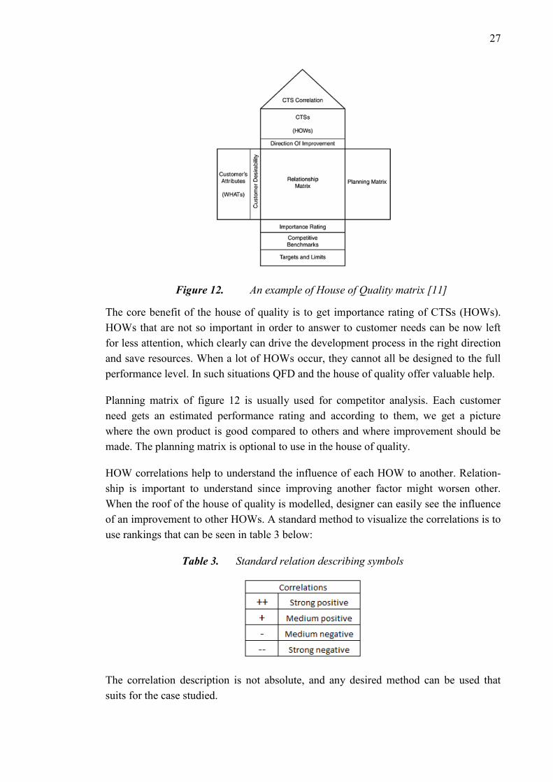
In figure 12 can be seen an example of a house of quality table. When all the necessary
information has been added to the table, we get as a result importance rating of each
CTSs. CTSs equal to engineering requirements and by knowing the importance in rela-
tion to satisfy customer needs, consideration of resource allocation can now be made.
CTSs are usually measurable elements for which we can choose the direction of im-
provement and give the CTS a value.
27
Figure 12. An example of House of Quality matrix [11]
The core benefit of the house of quality is to get importance rating of CTSs (HOWs).
HOWs that are not so important in order to answer to customer needs can be now left
for less attention, which clearly can drive the development process in the right direction
and save resources. When a lot of HOWs occur, they cannot all be designed to the full
performance level. In such situations QFD and the house of quality offer valuable help.
Planning matrix of figure 12 is usually used for competitor analysis. Each customer
need gets an estimated performance rating and according to them, we get a picture
where the own product is good compared to others and where improvement should be
made. The planning matrix is optional to use in the house of quality.
HOW correlations help to understand the influence of each HOW to another. Relation-
ship is important to understand since improving another factor might worsen other.
When the roof of the house of quality is modelled, designer can easily see the influence
of an improvement to other HOWs. A standard method to visualize the correlations is to
use rankings that can be seen in table 3 below:
Table 3. Standard relation describing symbols
The correlation description is not absolute, and any desired method can be used that
suits for the case studied.

28
Additional aspects that could be added to the house of quality are for example technical
difficulty of implementation and target value of each engineering task (HOW).
In figure 13 can be seen a possible way to use QFD, the waterfall decomposition of
QFD. The waterfall decomposition process is converting the requirement to the tech-
nical information in the design and manufacturing process through house of quality, in
order to apply the requirement to the product development process that from conceptual
design to the technics design stage, which includes four stages: product plan, compo-
nent configuration, technics plan and manufacturing plan.
Figure 13. The waterfall decomposition process of QFD [28]
2.6 Analytic hierarchy process
Analytic hierarchy process (AHP) is a widely used tool among decision makers and
researchers, especially for multiple criteria problems. It is based on mathematics and
psychology and can be used in fields of planning, selecting an alternative, resource allo-
cations, resolving conflict, optimization, etc. [19]. Rather than finding the globally best
solution, AHP finds the best solutions that suit the goals and needs that are stated.
AHP is an Eigen value approach to the pair-wise comparisons. Pair comparison is made
between each alternative by giving a number value, which describes the relationship.
Comparison scales from 1/9 to 9, where 1/9 means least valued and 9 absolute more
important. Value 1 indicates that comparison objectives are equal in terms of im-
portance.
As initial information, AHP requires a problem, criterion and alternatives. In engineer-
ing, criterions can be for example customer needs or price. Alternatives are different
solutions to solve the problem. Alternatives are compared by using the criterions indi-
vidually. Criterions have their own weights, which indicate their importance to the deci-

29
sion making. Weights allow the decision maker to compare each pair in a rational and
consistent way, which makes AHP a powerful tool as hierarchy gets complex.
Key steps to perform an AHP [19]:
1. State the problem
2. Broaden the objectives of the problem
3. Identify the criterion
4. Structure the problem in hierarchy of different levels
5. Compare each element in the corresponding level and calibrate them on the nu-
merical scale. n(n – 1)/2 comparisons are required
6. Perform calculations to find the maximum Eigen value, consistency index CI,
consistency ratio CR, and normalized values for each criteria/alternative
7. If the maximum Eigen value, CI, and CR are satisfactory then decision is taken
based on the normalized values; else the procedure is repeated
In this thesis, the Eigen value finding process is not performed manually but with a tool
[31], that solves the value automatically. Tool only requires the matrix as initial infor-
mation and will then provide the solutions.
2.7 Finite element method
Structural analysis is a significant part of product development in order to create opti-
mized designs. A structural analysis provides information if the design is capable to
withstand all to it set load requirements. Structural analysis can be a great tool for opti-
mization process when weight, costs and construction are optimization targets. In to-
day’s world where structural analysis tools are able to perform even rather complicated
calculations in a short time, they can be very useful what it comes to optimization and
validation of design.
Finite element method (FEM) is a dominant computational method in engineering and
structural analysis. As CPUs of computers have developed, FEM together with other
computational tools have been a great help to engineers to analyze and simulate the de-
sign entities before manufacturing any of them.
FEM computational procedure starts with dividing the geometry of the design entity
into several subdivisions [13]. A subdivision is called an element, which consists of
nodes. A model of design entity is formed by having a big amount of elements which
form together a mesh which represents the geometry of the design entity. Elements can
be in shape of triangle, quadrilateral, tetrahedron, or hexagon. In figure 14 can be seen
possible shapes of elements.

30
Figure 14. Examples of elements [13]
Finite element method can be used for stress, temperature, fluid flow, and displacement
calculations for instance. Each element is a structure of nodes and the subgoal is to es-
tablish the stiffness relation for all the elements and then to the structure. The following
stiffness relation serves as the basis for the matrix displacement method [14]:
𝐹 = 𝐾 ∗ 𝑢 (1)
where F is the matrix consisting nodal forces, K is the stiffness matrix and u is the dis-
placement matrix that contains all the nodal displacements. A single element is the basic
unit for the problem and it is coupled to the whole structure by nodes. That way we are
able to solve displacement and force in every single node if the compatibility and equi-
librium are fulfilled [14].
A structure can be analyzed by using FEM either by linear or non-linear analysis. Linear
analysis is lighter calculation-wise as iteration loops are not always necessary to per-
form in order to find a solution. The linear analysis assumes material to behave elastic
at any given stress level, which causes error when yield stress has been exceeded. For
cases where yield strength is not exceeded or very detailed and accurate results are not
required, linear analysis provides sufficient results.
Nonlinear analysis on the other hand provides more precise solutions in cases where
materials yield strength is exceeded since phenomena such as plastic hardening are tak-
en into account [14]. Analysis can be carried out with elastoplastic materials for exam-
ple steel, which first behave elastic with small loads, but when load is increased further
elastic limit, plastic deformation will occur.
2.8 ADR regulations
ADR is an agreement that was done at Geneva on 30 September 1957 under the auspi-
ces of the United Nations Economic Commission for Europe and it entered into force on
29 January 1968. ADR defines provisions for transporting dangerous goods on road
among contracting parties. [1] It is also used as a guideline for making national regula-
tions for transporting dangerous goods.
At the time of publishing (1st January 2017), the Contracting Parties are Albania, An-
dorra, Austria, Azerbaijan, Belarus, Belgium, Bosnia and Herzegovina, Bulgaria, Croa-
tia, Cyprus, Czech Republic, Denmark, Estonia, Finland, France, Germany, Greece,

31
Hungary, Iceland, Ireland, Italy, Kazakhstan, Latvia, Liechtenstein, Lithuania, Luxem-
bourg, Malta, Montenegro, Morocco, Netherlands, Norway, Poland, Portugal, the Re-
public of Moldova, Romania, Russian Federation, Serbia, Slovakia, Slovenia, Spain,
Sweden, Switzerland, Tajikistan, the former Yugoslav Republic of Macedonia, Tunisia,
Turkey, Ukraine and United Kingdom. ADR applies to transport operations performed
on the territory of at least two of the above-mentioned Contracting Parties. [1] ADR
regulations are commonly used as a base of national codes of transportation of danger-
ous goods in Europe.
2.8.1 Strength requirements
ADR determines in the provision 9.7.3. that fastenings of the carriage shall be designed
to withstand static and dynamic stresses in normal conditions of carriage, and minimum
stresses as defined in provisions 6.8.2.1.2, 6.8.2.1.11 to 6.8.2.1.13, 6.8.2.1.15 and
6.8.2.1.16 in the case of tank-vehicles, battery-vehicles, and vehicles carrying demount-
able tanks. [1] The provisions are presented later in this thesis. The chapter 6.7 of ADR
determines requirements for the design, construction, inspection and testing of portable
tanks and United nation (UN) type of multi-element gas containers (MEGC). The chap-
ter 6.8 of ADR defines provisions for design, construction, inspection and testing of
demountable tanks, tank containers, tank swap bodies and MEGCs that are not UN type.
Provision 9.7.3 applies to fastenings, which are used to connect vehicle and a (tank)
container. According to provision 9.7.1.2, the entire unit shall meet the requirements
prescribed for tank-vehicles once a demountable tank has been attached to the carrier
vehicle [1]. That means that all the fastenings that play role in demountable body at-
tachment, have to meet the requirements that are set for tank-vehicles.
The provisions that concern this project are requirements for design, construction and
approval of vehicles. In other words, the fastenings have to fulfill the strength require-
ments that ADR sets. According to ADR, provision 6.8.2.1.2, the fastenings that are
used to secure a container shall, under the maximum permissible load (MPGM), be ca-
pable of absorbing the following separately applied static forces:
a) In the direction of travel: twice the MPGM multiplied by the acceleration due
to gravity (g)
b) Horizontally at right angles to the direction of travel: the MPGM (when the
direction of travel is not clearly determined, the forces shall be equal to twice the
MPGM) multiplied by the acceleration due to gravity
c) Vertically upwards: the MPGM multiplied by the acceleration due to gravity
(g); and
d) Vertically downwards: twice the MPGM (total loading including the effect of
gravity) multiplied by the acceleration due to gravity (g) [1]

32
Provision of point (b) requires defining the direction of travel or otherwise the force that
needs to be absorbed is 2G to all horizontal directions. The direction of travel is chosen
to be forward on this project since a truck can be assumed to be driven forward when
transportation of carriage is performed. The truck can be driven rearwards but it is not
considered as a direction of travel since the velocity stays reasonable low and does not
create possibilities of big accelerations in normal driving conditions. Hypothetically
thought, a truck could be loaded on a train. That way it could travel either rearward or
forward but since ADR only determines regulations for on-road haulage, it can be left
out from the scope and assume that sufficient additional securing is performed if a truck
is mounted on a train and truck’s direction of travel switches rearward for example.
Above-mentioned accelerations apply to all kind of fastenings that hold the container
that is carrying dangerous goods. In addition, ADR provision 9.7.3 sets requirements for
materials maximum stress and material type that can be used in construction. However,
the requirements apply only for fastenings that are directly connecting a welded tank to
the vehicle, or to fastenings that are under the effect of tank pressure when the test pres-
sure is applied to the tank.
In ADR regulations goods are classified into 9 different classes. Class 1, for instance, is
class of explosive substances and articles. Then there are classes for flammable materi-
als, gases, toxic, corrosive and oxidizing substances. [1]
ADR provisions do not apply to any transportation of dangerous goods. There are ex-
emptions related to the nature of the transport operation. For instance, provisions do not
apply [1]:
The carriage by private individuals where goods in question are packaged for re-
tail sale and are intended for their personal or domestic use or for their leisure or
sporting activities.
Emergency transport intended to save human lives or protect the environment
provided that all measures are taken to ensure that such transport is carried out
in complete safety
The carriage undertaken by enterprises which is ancillary to their main activity,
such as deliveries to or returns from building or civil engineering sites, or in re-
lation to surveying, repairs and maintenance, in quantities of not more than 450
litres per packaging, including intermediate bulk containers (IBCs) and large
packagings, and within the maximum quantities specified in the provision
1.1.3.6. Measures shall be taken to prevent any leakage of contents in normal
conditions of carriage. These exemptions do not apply to Class 7.
Carriage undertaken by such enterprises for their supply or external or internal
distribution does not fall within the scope of this exemption. [1]

33
2.8.2 Container types and condition requirements
ADR determines several different type of containers that can be used to carry dangerous
goods. Most of the design requirements concern of the construction of tank shells and
tank’s supporting frames.
Portable tank means a multimodal tank having, when used for the carriage of gases as
defined in the provision 2.2.2.1.1, a capacity of more than 450 liters in accordance with
the definitions in chapter 6.7 of ADR or the International maritime code of dangerous
goods (IMDG) and indicated by a portable tank instruction (T-Code) in Column (10) of
Table A of Chapter 3.2. [1] Portable tank can have a frame equipped with corner casting
that can be locked to or with a twistlock and it shall have equivalent strength to bulk
container.
Tank-container means an article of transport equipment meeting the definition of a con-
tainer, and comprising a shell and items of equipment, including the equipment to facili-
tate movement of the tank-container without significant change of attitude, used for the
carriage of gases, liquid, powdery or granular substances and, when used for the car-
riage of gases as defined in 2.2.2.1.1, having a capacity of more than 0.45 m3 (450 li-
tres). [1] An example of a tank container is presented in the figure 15.
Figure 15. Typical tank-container for military use [24]
Demountable tank means a tank, other than a fixed tank, a portable tank, a tank-
container or an element of a battery-vehicle or a MEGC, which has a capacity of more
than 450 litres, is not designed for the carriage of goods without breakage of load, and
normally can only be handled when it is empty. [1]
Multiple-element gas container (MEGC) means a unit containing elements which are
linked to each other by a manifold and mounted on a frame. The following elements are
considered to be elements of a multiple-element gas container: cylinders, tubes, pressure
drums or bundles of cylinders as well as tanks for the carriage of gases as defined in
2.2.2.1.1 having a capacity of more than 450 litres. [1]

34
Bulk container means a containment system (including any liner or coating) intended
for the carriage of solid substances which are in direct contact with the containment
system. Packagings, intermediate bulk containers (IBCs), large packagings and tanks
are not included. [1]
Also, following definitions determine a bulk container [1]:
permanent character and accordingly strong enough to be suitable for repeated
use;
specially designed to facilitate the carriage of goods by one or more means of
transport without intermediate reloading
specially designed to facilitate the carriage of goods by one or more means of
transport without intermediate reloading
fitted with devices permitting its ready handling; of a capacity of not less than
1.0 m3
Examples of bulk containers are containers, offshore bulk containers, skips, bulk bins,
swap bodies, trough-shaped containers, roller containers, load compartments of vehi-
cles. [1] This means that ISO-containers can be considered as bulk containers in ADR.
ADR provision 7.1.4 set regulations for the condition of container that carries danger-
ous goods. The container has to be “structurally serviceable” which means that it is free
from “major defects” in its structural components, for example, its top and bottom rails.
Major defects are listed below:
dents or bends in structural members greater than 19mm in depth, regardless of
length
cracks or breaks in structural members
more than one splice or an improper splice (e.g. a lapped splice) in top or bottom
end rails or door headers or more than two splices in any one top or bottom side
rail or any splice in a door sill or corner post
door hinges and hardware that are seized, twisted, broken, missing or otherwise
inoperative
non-closing gaskets and seals; any distortion of the overall configuration suffi-
cient to prevent proper alignment of handling equipment, mounting and securing
on a chassis or vehicle
deterioration in any component of the container, for example, rusted metal in
side walls or disintegrated fiberglass is unacceptable, regardless of the material
of construction
However, normal wear, including oxidization (rust), slight dents and scratches and other
damage that do not affect serviceability or weather-tightness are, however, acceptable.
[1]

35
All the above-mentioned containers can be handled with a hooklift excluding demount-
able tanks, which are not usually equipped with corner castings and rails or other inter-
faces that could be attached to hooklift or lifting frame. On the other hand, a
demountable container could be for example, attached on a flatrack, which then must
fulfill the ADR regulations.
2.8.3 Carriage other than by road
ADR provision 1.1.4.5 determines regulations for carriage other than by road. Accord-
ing to the provision: “…any national or international regulations which, on the said
section, govern the carriage of dangerous goods by the mode of transport used for con-
veying the road vehicle shall alone be applicable to the said section of the journey.” [1]
ADR provision states in other words that if transport operation is carried out for exam-
ple by rail, the regulation there should be applied the regulation that concerns rail haul-
age.
Generally, ADR provisions apply only when transport operations are performed on the
territory of at least two of the ADR contracting parties [1]. On the other hand, ADR is a
guideline and base of the provisions for transporting of dangerous goods in many coun-
tries in Europe. For instance, in Finland, we have a law “Vaarallisten aineiden kuljetus”
(VAK), which mentions ADR in the law itself.
2.8.4 Application of standards
Where the application of a standard is required and there is any conflict between the
standard and the provisions of ADR, the provisions of ADR take precedence. The re-
quirements of the standard that do not conflict with ADR shall be applied as specified,
including the requirements of any other standard, or part of a standard, referenced with-
in that standard as normative. [1]
2.8.5 ADR in the future
Currently, ADR does not clearly set any specific fastening requirements to demountable
containers that are secured or transported by a truck that is equipped with a hooklift.
Generally, a hooklift is not a typical equipment for transporting dangerous goods, and
therefore any provision is not clearly targeted to it. On the other hand, militaries use
hooklifts to transport of dangerous goods and authorities require that the whole unit is
then ADR compliant.
The government of Norway has noticed the ambiguity in regulations and brought it in
2015 to a UNECE meeting as a concern [9]. The government of Norway pointed out
that strength requirement of fastenings should cover all of the container types and any
frames or other devices used for support of such fastenings on the vehicle. This would

36
unequivocally concern hooklifts as well then. A proposal for changing the ADR by
Norway in 2016 [8].
Norway’s proposal has been adopted by the working party in the 102nd held on 2 June
2017. Provision 9.7.3. concerning the fastenings, starting from 1 January 2019 is going
to be clarified in following way:
“9.7.3 Fastening
9.7.3.1 Fastenings shall be designed to withstand static and dynamic stresses in
normal conditions of carriage. Fastenings also include any supporting
frames used for mounting the structural equipment (see 1.2) to the vehicle.
9.7.3.2 Fastenings in the case of tank-vehicles, battery-vehicles and vehicles car-
rying tank-containers, demountable tanks, portable tanks, MEGCs or UN MEGCs shall
be capable of absorbing, under the maximum permissible load, the following separately
applied static forces:
- In the direction of travel: twice the total mass multiplied by the acceleration
due to gravity (g)1 ;
- At right angles to the direction of travel: the total mass multiplied by the accel-
eration due to gravity (g)1 ;
- Vertically upwards: the total mass multiplied by the acceleration due to gravity
(g)1 ;
- Vertically downwards: twice the total mass multiplied by the acceleration due
to gravity (g)1
NOTE: The requirements of this paragraph do not apply to twist lock tie-down
devices in compliance with ISO 1161:2016 “Series 1 freight containers -- Corner and
intermediate fittings – Specifications”. However, the requirements apply to any frames
or other devices used for support of such fastenings on the vehicle.”. [7],[32]
The main difference that has been added is that now the ADR clearly points out that
fastenings also include any supporting frames used for mounting a container. Previously
it has been only matter of assuming it for example in hooklift case. Provision 9.7.3.2
would now clearly point out that ADR concerns fastenings of tank-containers, portable
tanks, demountable tanks, UN-MEGCs and MEGCs, which is not directly determined in
the current version of ADR.
2.9 Summary of the theory
Figure 16 below presents shortly the theories that were presented in this chapter. From
the figure we can see where theories locate themselves in the big picture.

37
Figure 16. Overview of the presented theories and their relations
The whole product development process requires first motivation where it starts. Moti-
vation factors are company strategy, customer/market demands and supply chain chang-
es. Those factors set objectives for the project and for the product. When motivation to
begin a product development project is created, a method how to carry out the process is
needed. The method in the diagram is lean product development, which is base of
DFSS. DFSS principles are a tool to fight against product development waste.
DFSS divides into four phases. Tools that are used in each phase are presented in figure
16. QFD is used as a tool to help to illustrate the relationshipship between each re-
quirement and design task and element. Understanding the relationships between the
design element helps to carry out design work with fewer iteration loops since the rela-
tions are considered already at the start and not after the problem is noticed.
In the second DFSS phase, brainstorming and TRIZ are utilized to create concepts. For
deciding the concept that is going to be used, AHP is used to support the decision-
making. It provides rational information and is, therefore, a great tool to use at this
point. In figure 17 can be seen more detailed view of “characterize the design” phase of
the DFSS and how it is applied to this thesis. As can be seen, the input is product re-
quirements, which has been determined in the previous DFSS phase. The process ends
to moving into the optimization phase. The process diagram illustrates the characteriz-
ing process that is carried out in this thesis. As seen in the figure, an iteration loop oc-
curs, if improved design or a new concept does not comply with the product require-
ments. This loop is performed as many times as needed to fulfills the product require-
ments.

38
Figure 17. Process diagram of characterize phase (C) of DFSS
In the third phase, the design is analyzed and optimization activities are carried out. To
drive the design towards optimum, FEM and prototyping are used as support and infor-
mation source. In the final phase, the validation process is performed. In this thesis, the
validation process is not carried out completely and it focuses on the first three phases
of DFSS process.
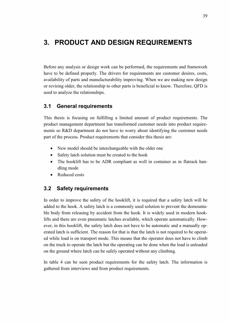
39
3. PRODUCT AND DESIGN REQUIREMENTS
Before any analysis or design work can be performed, the requirements and framework
have to be defined properly. The drivers for requirements are customer desires, costs,
availability of parts and manufacturability improving. When we are making new design
or revising older, the relationship to other parts is beneficial to know. Therefore, QFD is
used to analyze the relationships.
3.1 General requirements
This thesis is focusing on fulfilling a limited amount of product requirements. The
product management department has transformed customer needs into product require-
ments so R&D department do not have to worry about identifying the customer needs
part of the process. Product requirements that consider this thesis are:
New model should be interchangeable with the older one
Safety latch solution must be created to the hook
The hooklift has to be ADR compliant as well in container as in flatrack han-
dling mode
Reduced costs
3.2 Safety requirements
In order to improve the safety of the hooklift, it is required that a safety latch will be
added to the hook. A safety latch is a commonly used solution to prevent the demounta-
ble body from releasing by accident from the hook. It is widely used in modern hook-
lifts and there are even pneumatic latches available, which operate automatically. How-
ever, in this hooklift, the safety latch does not have to be automatic and a manually op-
erated latch is sufficient. The reason for that is that the latch is not required to be operat-
ed while load is on transport mode. This means that the operator does not have to climb
on the truck to operate the latch but the operating can be done when the load is unloaded
on the ground where latch can be safely operated without any climbing.
In table 4 can be seen product requirements for the safety latch. The information is
gathered from interviews and from product requirements.
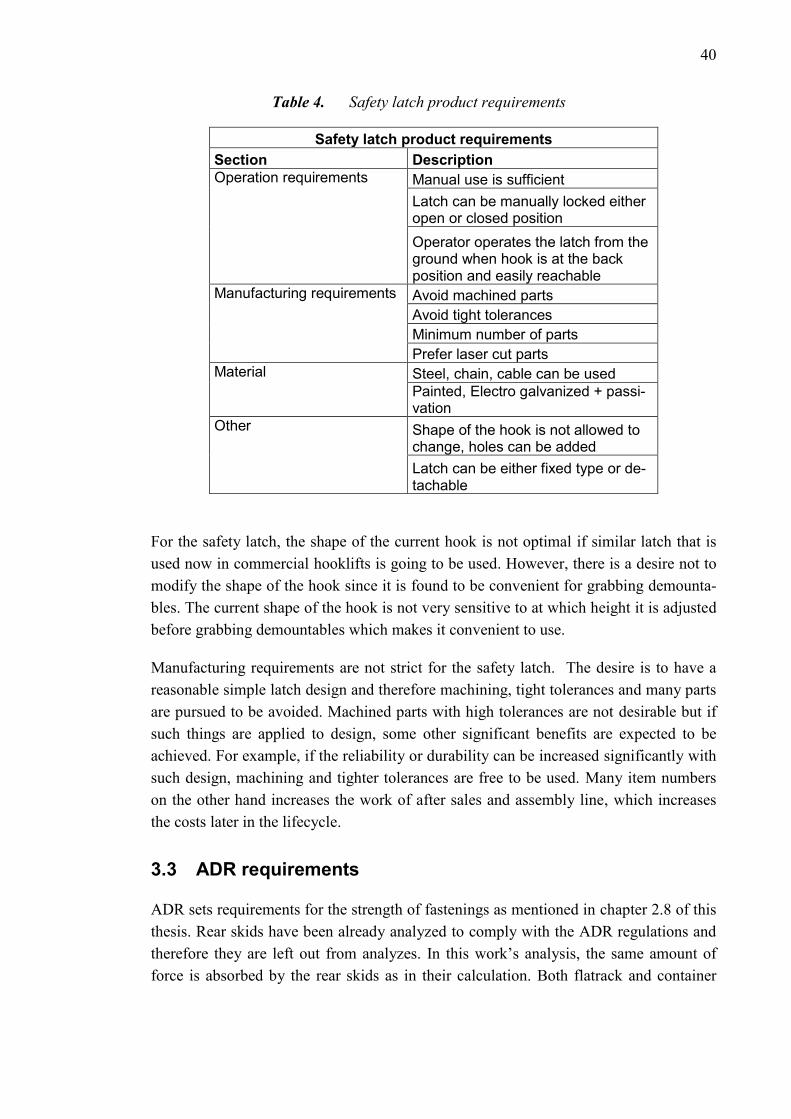
40
Table 4. Safety latch product requirements
Safety latch product requirements
Section Description
Operation requirements Manual use is sufficient
Latch can be manually locked either open or closed position
Operator operates the latch from the ground when hook is at the back position and easily reachable
Manufacturing requirements Avoid machined parts
Avoid tight tolerances
Minimum number of parts
Prefer laser cut parts
Material Steel, chain, cable can be used
Painted, Electro galvanized + passi-vation
Other Shape of the hook is not allowed to change, holes can be added
Latch can be either fixed type or de-tachable
For the safety latch, the shape of the current hook is not optimal if similar latch that is
used now in commercial hooklifts is going to be used. However, there is a desire not to
modify the shape of the hook since it is found to be convenient for grabbing demounta-
bles. The current shape of the hook is not very sensitive to at which height it is adjusted
before grabbing demountables which makes it convenient to use.
Manufacturing requirements are not strict for the safety latch. The desire is to have a
reasonable simple latch design and therefore machining, tight tolerances and many parts
are pursued to be avoided. Machined parts with high tolerances are not desirable but if
such things are applied to design, some other significant benefits are expected to be
achieved. For example, if the reliability or durability can be increased significantly with
such design, machining and tighter tolerances are free to be used. Many item numbers
on the other hand increases the work of after sales and assembly line, which increases
the costs later in the lifecycle.
3.3 ADR requirements
ADR sets requirements for the strength of fastenings as mentioned in chapter 2.8 of this
thesis. Rear skids have been already analyzed to comply with the ADR regulations and
therefore they are left out from analyzes. In this work’s analysis, the same amount of
force is absorbed by the rear skids as in their calculation. Both flatrack and container
41
carriage have to fulfill the ADR provisions. ADR requirements divide into two top lev-
el:
Strength requirements for flatrack fastenings
Strength requirements for container fastenings
Strength requirements divide into different load cases depending on the direction of the
force. The amount of force applied to the structure is determined by the ADR regula-
tions.
3.4 Interchangeability requirements
The new hooklift and CHU model are required to be interchangeable with the old hook-
lift and CHU. Interchangeability requirement has been identified by the sales company
and product management department. In principle, interchangeability means that the
new hooklift has to be able to operate an old lift frame and vice versa. Factors that effect
on the operate ability are listed below:
The new lift frame has to be able to be secured by using ratchets that have
twistlocks
New lift frame should fit to old hooklifts ratchets and vice versa
Geometry of the lift frame shall be rather similar to avoid any collisions when
using different lift frames
Container locking geometry has to be same between the new and old lift frame
so that either model of rear sliders can be used to secure the container
3.5 Relationship between product requirements and design
variables
After identifying the product requirements, a design relationship map can be modelled
to assist the designer to understand correlation between each requirement and task. For
the new design, correlation between the design variables is an important factor to be
aware of when pursuing the best possible overall solution. Requirements are first
modelled as a mind map, which is then easy to turn into design relationship matrix.
Mindmap can be seen in figure 18 below.

42
Figure 18. Relationships between design requirements and design objects
Table 5 illustrates house of quality table that has been derived from the mind map. In
the house of quality, each product requirement has their own importance coefficient.
Also, each product requirement has couple of design objects that pursues to satisfy
them. Product requirements are ranked by thinking the critical-to-satisfaction factor of
each of them. The more important the product requirement is, in general, the more value
it has. Values are determined by the designer. For load cases downward is given only a
value 1 for coefficient since it is not believed to affect the design that much or to be the
critical requirement that drives the design.

43
Table 5. Design variable and task relationship matrix (House of quality)
Desired direction of improvements are presented with arrows for each design objective
that is measurable. Relationships between product requirements and design objects are
modelled by using symbols. Each symbol represents a level of relation between the ob-
jects. A blank box equals no relationship between the object and requirement.
The correlations between design objects are described in the roof of house of quality
table. The same symbols are used as in the previous relation description. The reason for
not using standard negative/positive symbols is that in this context, we are more inter-
ested just, which design objects have relations to another and how strong is the relation.
Finally, we receive importance value of each design objective. Values are calculated by
using the relative importance of product requirement as a weight factor and then sum-
ming up the relation values multiplied by each weight. After that, the importance value
is transformed into relative importance to make it easier to compare. In the figure 19 can
be seen the design objectives sorted by the importance.

44
Figure 19. Engineering tasks sorted by the importance level
Importance indicates the amount of relation in order to satisfy the product requirements.
According to the chart in figure 19, the strength of the skids is the most important factor
and has most relations to the engineering tasks or design objects. The strength of the
lower lock has second biggest value followed by the din locks.
Results of the house of quality give an overview of the influence potential of each de-
sign objective to the product requirements. The benefit of knowing this is that now more
resources can be used to the high-value objects and designer notices that the higher the
value is the more the design element affects to the fulfillment of requirements. In other
words, high value objects are more critical to more elements.
3.6 Product value influences
The reason behind each product requirement is that the value of the product would in-
crease. Product value increases by increasing the customer value and by decreasing
overall costs. Customer value is a bit hard to define or present in a numeric form. In
general, customer value can be defined: “A consumer’s assessment of the overall capac-
ity of a product to satisfy his or her needs [11].” On the other hand, satisfaction can be
divided into factors such as customer effort score, service experience, net promoter
score or user experience and context of use [25].

45
Anyhow, the product value in this project is pursued to be increased by following fea-
tures:
New lift frame and rear slide system
Safety latch
ADR compliant equipment
Interchangeability
The listed features are not only part of the improvements of the whole project. Above
mentioned are included in the scope of this thesis.
New lift frame and a rear sliding system increase the value by lowering the overall costs
that they cause in the whole lifecycle. They offer the same features to the customer as
the previous models but for the company, they are more cost-efficient to manufacture
and purchase. In addition, delivery time is expected to be shorter due to harmonization
possibilities to other existing products. Design of the new lift frame and the sliding
system is more suitable for the modern manufacturing processes and therefore it is more
cost-efficient than the older design. For example, laser cutting accuracy has increased
over the years, which has enabled designers to create the design so that laser cutting can
be effectively utilized.
Rear slide system with skids is a new solution in container handling. The old roller type
system is more expensive to manufacture and it has been noticed to damage the rails of
a container over the time by bending the rail. In the new sliding system, the skids pro-
vide a flat support surface for the container and therefore damages the rails less. On the
other hand, friction increases in the load cycles, but not that much that capacity of the
equipment would lower.
Safety latch increases the safety level of the product. Today’s standards require the
product to be very safe, which is why a safety latch had to be designed. For the custom-
er it is great solution especially in the lift frame operation where the risk of dropping the
frame is high.
ADR compliance is a basic requirement for military equipment. It is hard to calculate
the value it brings but even easier to calculate loses if the equipment is not ADR com-
pliant since no military wants to get an equipment that is not ADR compliant.
Interchangeability increases the customer value of the product as it can be used to oper-
ate older CHU equipment without a problem. For a customer that has older MPH165
equipment, interchangeability brings great value, since any hooklift can be used with
any lift frame without worrying which model of the hooklift is in the use.

46
4. DEFINITION OF CURRENT STATE OF DESIGN
To be able to make the product better, the current state of the design has to be known.
The current design can then be compared to the newer one and benefits and product
value can then be better understood.
4.1 Hooklift and new equipment
Hooklift is equipped with a new type of rear sliding system and a new type of lift frame.
Sliding system already fulfills the product requirements which forces us to focus more
on the new lift frame. The idea is that the mechanical design of the hooklift remains in
outline rather unmodified and only necessary modifications are desired to be made.
4.2 Ratchets and securing of the lift frame
The current designs of the lift frame and its ratchets are from a former project. Current-
ly, the designs are not completely validated and, for example, the ratchet mounting and
some parts of the lift frame are not in use in any equipment yet. The ratchet design of
the older DROPS is not desired to be used in the new model since a more cost-efficient
solution is desired. The design of the new ratchet solution is not perfect from the operat-
ing point of view yet. The lift frame cannot be secured completely with the current so-
lution. Lift frame still remains loose even though the ratchets are tightened up complete-
ly. The reason is that the lift frame is quite flexible and the chosen ratchets cannot be
tightened up enough with current geometry since the “legs” of the lift frame starts to
bend. Ratchet is in the end tightened up to its maximum. In the figure 20 can be seen the
current solution of ratchet mounting.

47
Figure 20. Current design for securing the lift frame
The used ratchet is a top link that is used commonly in agricultural tractors. The ratchet
can be tightened up by twisting the middle section of it.
In table 6 can be seen the technical data of the new ratchet. The ratchet is a category 2
top link which maximum capacity is 120kN. Category of the ratchet indicates its
capacity that it can handle. In higher capacities the size of the shaft and ratchet
increases.
Table 6. Properties of the ratchet
Ratchet properties
Top link category Cat 2.
Maximum capacity 120kN
Minimum length 532mm
Maximum length 755mm
Swivel end mounting hole diameter
28mm
Ball end mounting hole diameter
25,4 (1 inch)
The minimum length of the ratchet is 532mm which is according to testing, too long for
the current mounting position.

48
Figure 21. Lift frame’s angle in relation to ratchets from above
As can be seen from figure 21, the ratchet has an angle rearward. Now, when the ratchet
is tightened up the lift frame moves rearwards until it reaches the same line that the
ratchet is mounted to. Only after that, it starts to tighten up. The current ratchet is too
long to be able to lock the lifting frame completely. Another thing that is identified is
that ratchets have to be tightened up quite a lot before frame starts to tighten up and
finally with the current ratchet length / mounting position does not.
Attaching ratchets to the lift frame is performed with a specific mounting bracket that
can be seen in figure 22. The bracket is designed to fit in a twistlock hole and to the
Walterscheid’s ratchet.
Figure 22. The current state of twistlock interface
The old, H-type lift frame has a twistlock interface and therefore the twistlock interface
is desired to the new one as well in order to retain the interchangeability. Currently, the
new lift frame is equipped with the twistlock interface as well but the strength is un-
known. Old DROPS hooklifts are equipped with ratchets that have twistlocks on the
other end and they can only be attached to a twistlock shaped hole.
4.3 Lift frame and locks
In figure 3 can be seen the lift frame that is used in this project. Noticeable is that the
structure of the new frame is much more elastic compared to former design. Currently,

49
the frame is too elastic so that it could be secured with ratchets that are mounted on the
current position. Therefore, there is a steel beam connecting the legs of the frame. Beam
prevents “legs” to move towards each other when ratchets are tightened up.
Figure 23 shows the current state of lift frame’s lower lock. The lock has, as mentioned,
a twistlock interface. The interface is already designed so that it is in the same position
as in H-type lift frame so position wise designer does not have to worry about it. The
strength of the structure is unknown what it comes to the ratchet mounting.
Figure 23. Current state of a lower lock
50
5. DESIGN ANALYSIS OF CURRENT STATE
In this chapter, the current state of design is analyzed. The target is to find out which
parts of the product already fulfill product requirements and which parts require modifi-
cations. The current state of design is presented in the previous chapter.
Product requirements to be analyzed:
Safety latch
Mechanical structure fulfills the ADR regulations
Product is interchangeable with older DROPS equipment
5.1 Interchangeability
The new MPH165 and its CHU has a requirement to be interchangeable with old mod-
els. Interchangeability means in this context that customer who has an old equipment
and wants to buy more can buy the facelifted model and operate with it an old lift frame
or replace an older hooklift model easily without major modifications to truck mount-
ing.
The new model shall be able to operate the old lift frame and vice versa. Securing the
lift frame to the transportation mode as well as operating it have to be possible to per-
form with either hooklift model.
Currently, the lift frame is interchangeable to the older one. However, securing the
frame does not work conveniently with the new ratchets. The lift frame still moves a lot
even though the ratchets are tighten up completely. As already mentioned in chapter 4.2,
the mounting point has to be moved more forward in order to secure the frame properly.
5.2 Container handling load cases
ADR sets requirements for the fastenings to be capable of absorbing static forces that
were defined previously in chapter 2.8. Both container and the flatrack fastenings have
to fulfill the regulations. ADR study for skids has been already carried out and it can be
left out of the scope of this work’s analysis.
Before any analysis can be done the fixing points must be defined. Mounting of a
flatrack and container is different and therefore the study has to be done separately for

51
both applications. In every container load case, the force is applied to the center of a
container, which is assumed to be the center of gravity.
Figure 24 and 25 illustrate load ADR load cases. The direction of travel is to the left-
hand side in figure 24. As figure 24 shows, the container is fastened from the corner
fittings by rear slide unit (skids) and by the lift frame on the front.
Figure 24. ADR forces and the mounting points
Figure 25. Horizontal ADR forces
Ratchets are attached to the lift frame’s lower locks and they prevent the container to
jump and move sideward. On the back, the container is secured from its lower corner
fittings to rear sliding systems twistlocks.
5.2.1 Load case 1: forward
In this load case, a force of 2G is applied forward. According to the ADR, static force of
2G is applied to the direction of travel when it is defined.
In the container handling application, the load is carried following way:
50% of the load is absorbed by the hookarm and lift frame
50% of the load is carried by rear skids and their twistlocks
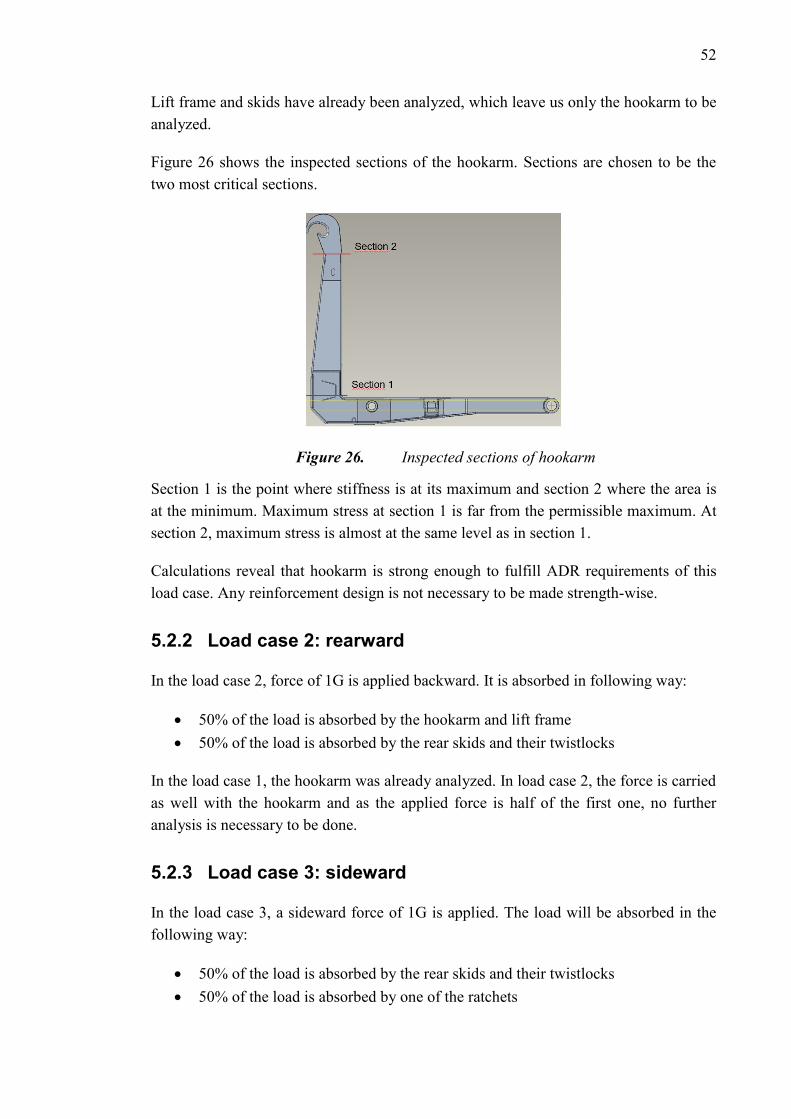
52
Lift frame and skids have already been analyzed, which leave us only the hookarm to be
analyzed.
Figure 26 shows the inspected sections of the hookarm. Sections are chosen to be the
two most critical sections.
Figure 26. Inspected sections of hookarm
Section 1 is the point where stiffness is at its maximum and section 2 where the area is
at the minimum. Maximum stress at section 1 is far from the permissible maximum. At
section 2, maximum stress is almost at the same level as in section 1.
Calculations reveal that hookarm is strong enough to fulfill ADR requirements of this
load case. Any reinforcement design is not necessary to be made strength-wise.
5.2.2 Load case 2: rearward
In the load case 2, force of 1G is applied backward. It is absorbed in following way:
50% of the load is absorbed by the hookarm and lift frame
50% of the load is absorbed by the rear skids and their twistlocks
In the load case 1, the hookarm was already analyzed. In load case 2, the force is carried
as well with the hookarm and as the applied force is half of the first one, no further
analysis is necessary to be done.
5.2.3 Load case 3: sideward
In the load case 3, a sideward force of 1G is applied. The load will be absorbed in the
following way:
50% of the load is absorbed by the rear skids and their twistlocks
50% of the load is absorbed by one of the ratchets
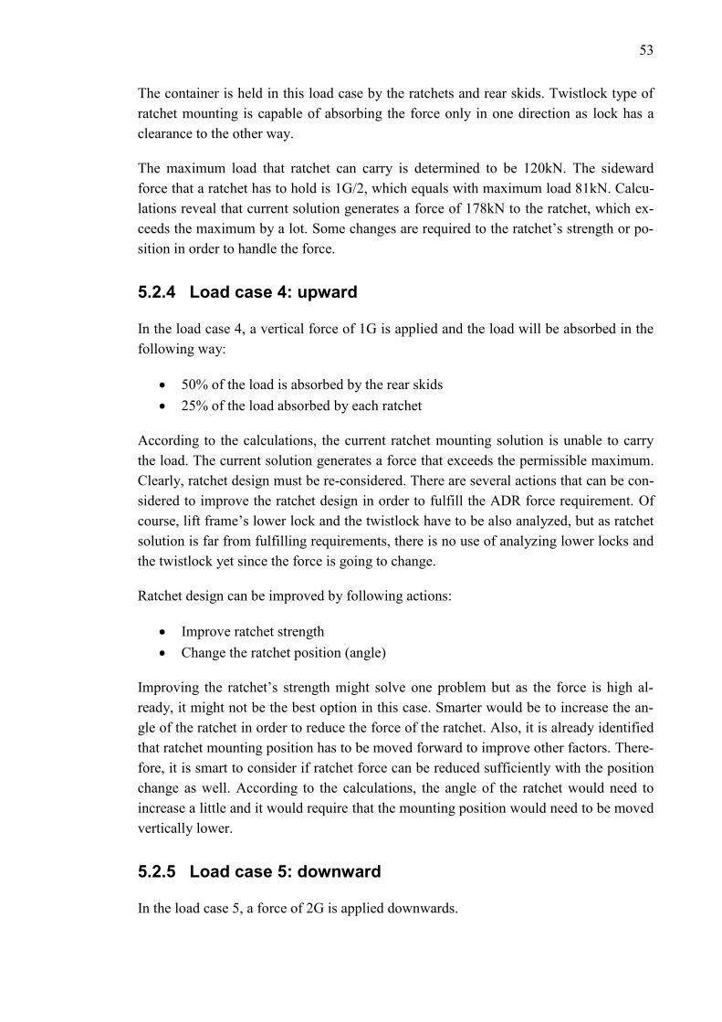
53
The container is held in this load case by the ratchets and rear skids. Twistlock type of
ratchet mounting is capable of absorbing the force only in one direction as lock has a
clearance to the other way.
The maximum load that ratchet can carry is determined to be 120kN. The sideward
force that a ratchet has to hold is 1G/2, which equals with maximum load 81kN. Calcu-
lations reveal that current solution generates a force of 178kN to the ratchet, which ex-
ceeds the maximum by a lot. Some changes are required to the ratchet’s strength or po-
sition in order to handle the force.
5.2.4 Load case 4: upward
In the load case 4, a vertical force of 1G is applied and the load will be absorbed in the
following way:
50% of the load is absorbed by the rear skids
25% of the load absorbed by each ratchet
According to the calculations, the current ratchet mounting solution is unable to carry
the load. The current solution generates a force that exceeds the permissible maximum.
Clearly, ratchet design must be re-considered. There are several actions that can be con-
sidered to improve the ratchet design in order to fulfill the ADR force requirement. Of
course, lift frame’s lower lock and the twistlock have to be also analyzed, but as ratchet
solution is far from fulfilling requirements, there is no use of analyzing lower locks and
the twistlock yet since the force is going to change.
Ratchet design can be improved by following actions:
Improve ratchet strength
Change the ratchet position (angle)
Improving the ratchet’s strength might solve one problem but as the force is high al-
ready, it might not be the best option in this case. Smarter would be to increase the an-
gle of the ratchet in order to reduce the force of the ratchet. Also, it is already identified
that ratchet mounting position has to be moved forward to improve other factors. There-
fore, it is smart to consider if ratchet force can be reduced sufficiently with the position
change as well. According to the calculations, the angle of the ratchet would need to
increase a little and it would require that the mounting position would need to be moved
vertically lower.
5.2.5 Load case 5: downward
In the load case 5, a force of 2G is applied downwards.
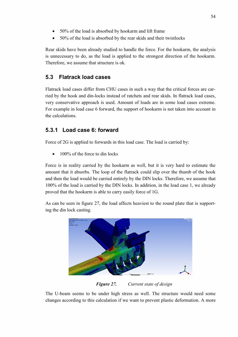
54
50% of the load is absorbed by hookarm and lift frame
50% of the load is absorbed by the rear skids and their twistlocks
Rear skids have been already studied to handle the force. For the hookarm, the analysis
is unnecessary to do, as the load is applied to the strongest direction of the hookarm.
Therefore, we assume that structure is ok.
5.3 Flatrack load cases
Flatrack load cases differ from CHU cases in such a way that the critical forces are car-
ried by the hook and din-locks instead of ratchets and rear skids. In flatrack load cases,
very conservative approach is used. Amount of loads are in some load cases extreme.
For example in load case 6 forward, the support of hookarm is not taken into account in
the calculations.
5.3.1 Load case 6: forward
Force of 2G is applied to forwards in this load case. The load is carried by:
100% of the force to din locks
Force is in reality carried by the hookarm as well, but it is very hard to estimate the
amount that it absorbs. The loop of the flatrack could slip over the thumb of the hook
and then the load would be carried entirely by the DIN locks. Therefore, we assume that
100% of the load is carried by the DIN locks. In addition, in the load case 1, we already
proved that the hookarm is able to carry easily force of 1G.
As can be seen in figure 27, the load affects heaviest to the round plate that is support-
ing the din lock casting.
Figure 27. Current state of design
The U-beam seems to be under high stress as well. The structure would need some
changes according to this calculation if we want to prevent plastic deformation. A more

55
detailed analysis should be carried out in this case to get more detailed information. In
more detailed analysis, bolts and the supporting surface should be modelled as well to
verify the validity of the results.
It has been identified that truck mounting is going to be changed. Now the mounting is
not at the same level with the front mounting, which is confusing. Therefore, a mount-
ing bracket, which is similar to the front mounting plate, is going to be used in the next
analysis.
5.3.2 Load case 7: rearward
In the load case 7, a force of 1G is applied rearwards. It is carried in the following way:
100% of the load to hookarm
As the rearward force might create a moment that lifts the hookarm, the hydraulics must
be analyzed. The hookarm is held still by hydraulic cylinders that are locked with load
control valves. The load control valves have pressure relief level, which shall not be
exceeded in order to prevent possible load escaping. According to calculations, the pres-
sure in the main cylinders exceeds slightly the setup of the pressure relief valve. How-
ever, it can be assumed that load does not escape as calculations do not include friction,
pressure loses or the fact that at some point, very soon after release, the hook will be the
load carrying component and not the rail supports. That would increase the moment
resisting the rotation and pressure would reduce under the set limit in main cylinders.
Strength of the hookarm was already studied in the load case 1. Applied force was 1G,
the same as in this load case. Therefore, we can state that hookarm has sufficient
strength.
5.3.3 Load case 8: sideward
In the load case 8, a force of 1G is applied sidewards. It is carried in following way:
50% of the load to DIN locks
50% of the load to middle frame of the hook
100% of the moment load to DIN locks
Middle frame of the hookarm is a strong component and it is left out from the calcula-
tions as it is not assumed to be the weakest link of the structure in this load case. The
weakest component is assumed to be the truck mounting or the DIN lock itself.
Rather high center of gravity in the flatrack calculations causes a force upwards to din
lock. Direct sideward force of G/4 affects the lock in addition. Figure 28 shows the
stresses caused by these forces.
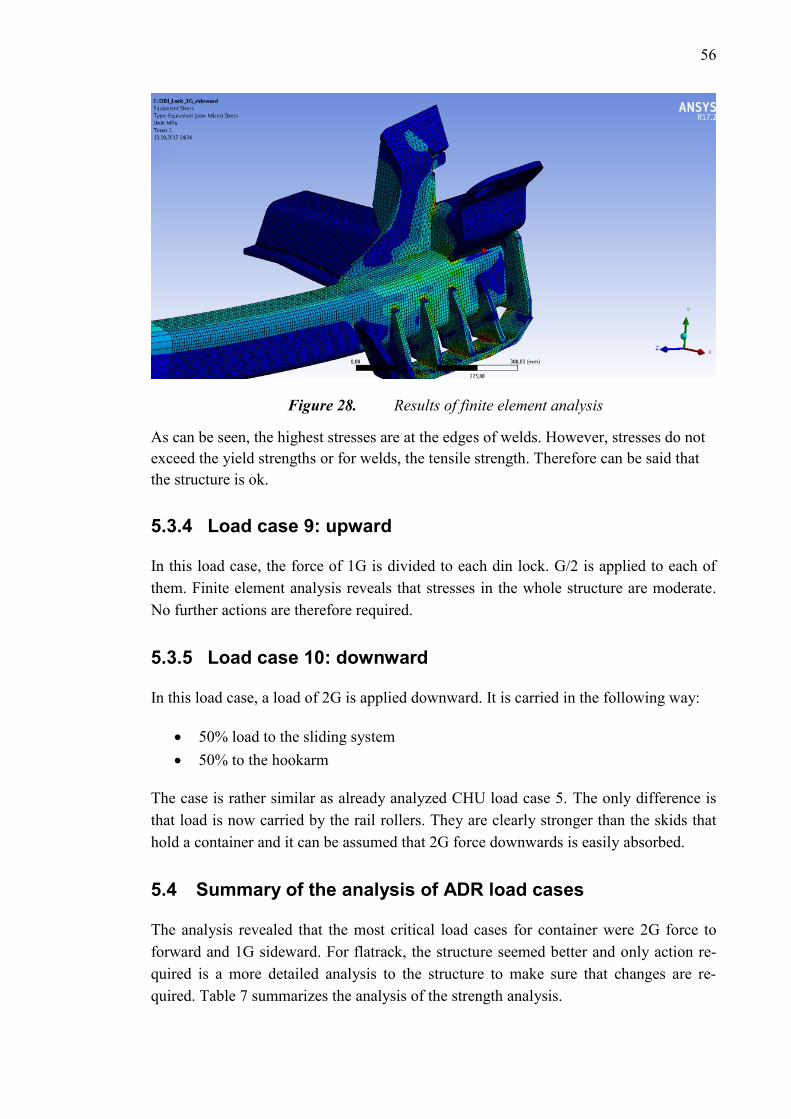
56
Figure 28. Results of finite element analysis
As can be seen, the highest stresses are at the edges of welds. However, stresses do not
exceed the yield strengths or for welds, the tensile strength. Therefore can be said that
the structure is ok.
5.3.4 Load case 9: upward
In this load case, the force of 1G is divided to each din lock. G/2 is applied to each of
them. Finite element analysis reveals that stresses in the whole structure are moderate.
No further actions are therefore required.
5.3.5 Load case 10: downward
In this load case, a load of 2G is applied downward. It is carried in the following way:
50% load to the sliding system
50% to the hookarm
The case is rather similar as already analyzed CHU load case 5. The only difference is
that load is now carried by the rail rollers. They are clearly stronger than the skids that
hold a container and it can be assumed that 2G force downwards is easily absorbed.
5.4 Summary of the analysis of ADR load cases
The analysis revealed that the most critical load cases for container were 2G force to
forward and 1G sideward. For flatrack, the structure seemed better and only action re-
quired is a more detailed analysis to the structure to make sure that changes are re-
quired. Table 7 summarizes the analysis of the strength analysis.

57
Table 7. Summary of the current state of ADR load cases

58
6. CONCEPT CREATION, ANALYSIS AND SE-
LECTION
In this chapter, concepts for identified problems and for solving them are created and
then analyzed. The previous chapter revealed issues in the design that are now going to
be solved in this chapter.
6.1 Safety latch
According to product requirements, safety latch must be added to the hooklift to fulfill
modern safety requirements. The type of safety latch is not defined in the product re-
quirements but it should be cost-efficient and easy to use. Safety latch will be used
when the hooklift is driven to the unload position. At that position, safety latch can be
operated easy and safe, operator standing on the ground. In addition, the safety latch
will be used only with lifting frame according to the product requirements.
Safety latch for hooklift itself is not an innovation. Therefore, existing safety latch con-
cepts are first studied. Plenty of variable solutions are already available on market. For
so-called commercial hooklifts, the customer can select a pneumatic safety latch that is
operated with a remote controller or a mechanically automatic safety latch, which works
by utilizing the earth’s gravity. Pneumatic safety latch would be the best option what it
comes to easy to use factor but the fact that it would require a completely new hook
design is a disadvantage of it. Gravity assisted automatically operating mechanical latch
would be an inexpensive solution.
The concept creation process starts by creating as many concepts as possible. According
to Yang [5], brainstorming is a powerful tool to create many concepts. The idea is to
create concepts without any filter at first. For creating safety latch concepts, a brain-
storming session was held in a group of three people and following ideas were received
from the session.
Final concept ideas:
1. Pneumatic safety latch
2. Gravity assisted safety latch
3. Chain or a securing cable
4. Detachable latch
5. Manual, hook fixed latch

59
The ideas represent different solutions of a safety latch in terms of operation principle.
Safety latches can be categorized into automatically-, semi-automatically-, and manual-
ly operated concepts. The pneumatic safety latch is the only solution that can be made
fully automatic. However, according to product requirements, an automatic solution is
not required, which might make the pneumatic latch a bit too “high-tech” solution for
the purpose.
Gravity assisted safety latch is a semi-automatic safety latch. Working principle is that
the latch opens when the hook is upside down automatically. When the hook is in the
normal position, gravity will move the latch to the locked position. This kind of solution
is not the safest option when operating with a lift frame since the highest risk of drop-
ping the frame from the hook is at the position where the hook is upside down.
Chain or securing cable is a concept where a chain or cable is attached to the hook. Se-
curing would be accomplished by making a loop around the bail bar with the cable. Se-
curing, in this case, would be a bit “loose” but costs of the concept is very low com-
pared to others. However, this kind of securing would look a bit unprofessional and
there is always a risk that cable or chain sticks to something.
Detachable latch concept is as the name says, completely detachable. The hook would
not require any changes with this concept but using it is a bit complicated compared to
other concepts. It would require a stowage somewhere in the hooklift as well. Since it is
not mounted to the hook, there is a risk of losing the latch by dropping it somewhere, in
the snow for example. This kind of latch is easy to forget to use as well.
The last concept is manual hook fixed latch. The latch would be attached to the hook
and operated manually. The concept could be made with rather low costs depending on
the design. Compared to the concept three, this would look more professional and
would provide a “proper” securing.
6.1.1 Concept selection
Now, we have five solid concepts that could each be the best solution. However, the
most suitable concept must be chosen, which then can be developed and optimized. To
support the decision-making, we will use AHP to receive rational and consistent results.
For the AHP we have selected following criterions:
Manufacturing price
Ease of use
Durability
Simplicity
Safety
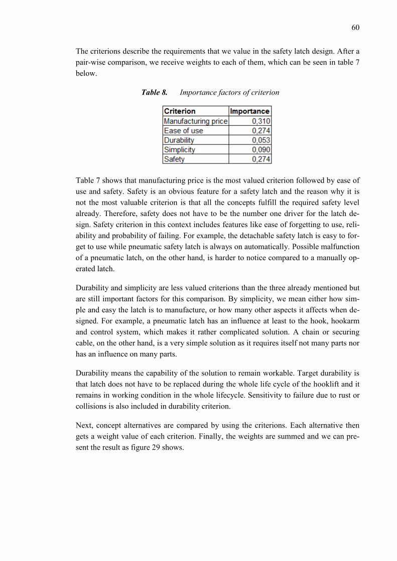
60
The criterions describe the requirements that we value in the safety latch design. After a
pair-wise comparison, we receive weights to each of them, which can be seen in table 7
below.
Table 8. Importance factors of criterion
Table 7 shows that manufacturing price is the most valued criterion followed by ease of
use and safety. Safety is an obvious feature for a safety latch and the reason why it is
not the most valuable criterion is that all the concepts fulfill the required safety level
already. Therefore, safety does not have to be the number one driver for the latch de-
sign. Safety criterion in this context includes features like ease of forgetting to use, reli-
ability and probability of failing. For example, the detachable safety latch is easy to for-
get to use while pneumatic safety latch is always on automatically. Possible malfunction
of a pneumatic latch, on the other hand, is harder to notice compared to a manually op-
erated latch.
Durability and simplicity are less valued criterions than the three already mentioned but
are still important factors for this comparison. By simplicity, we mean either how sim-
ple and easy the latch is to manufacture, or how many other aspects it affects when de-
signed. For example, a pneumatic latch has an influence at least to the hook, hookarm
and control system, which makes it rather complicated solution. A chain or securing
cable, on the other hand, is a very simple solution as it requires itself not many parts nor
has an influence on many parts.
Durability means the capability of the solution to remain workable. Target durability is
that latch does not have to be replaced during the whole life cycle of the hooklift and it
remains in working condition in the whole lifecycle. Sensitivity to failure due to rust or
collisions is also included in durability criterion.
Next, concept alternatives are compared by using the criterions. Each alternative then
gets a weight value of each criterion. Finally, the weights are summed and we can pre-
sent the result as figure 29 shows.
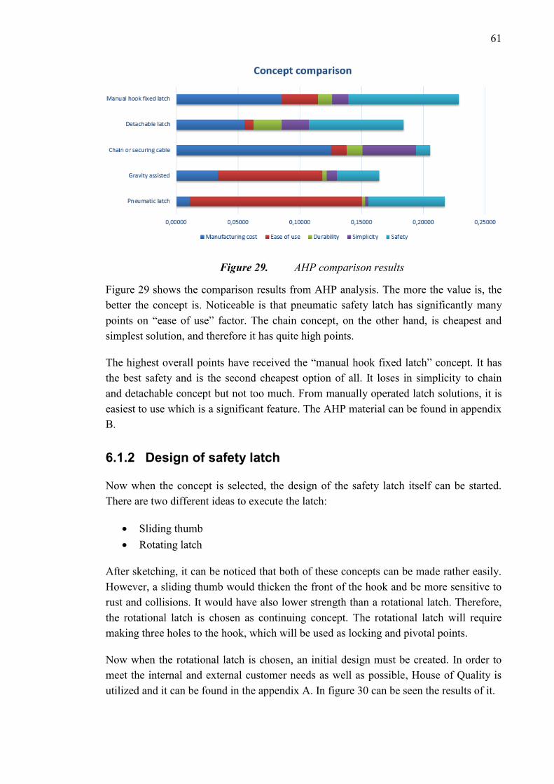
61
Figure 29. AHP comparison results
Figure 29 shows the comparison results from AHP analysis. The more the value is, the
better the concept is. Noticeable is that pneumatic safety latch has significantly many
points on “ease of use” factor. The chain concept, on the other hand, is cheapest and
simplest solution, and therefore it has quite high points.
The highest overall points have received the “manual hook fixed latch” concept. It has
the best safety and is the second cheapest option of all. It loses in simplicity to chain
and detachable concept but not too much. From manually operated latch solutions, it is
easiest to use which is a significant feature. The AHP material can be found in appendix
B.
6.1.2 Design of safety latch
Now when the concept is selected, the design of the safety latch itself can be started.
There are two different ideas to execute the latch:
Sliding thumb
Rotating latch
After sketching, it can be noticed that both of these concepts can be made rather easily.
However, a sliding thumb would thicken the front of the hook and be more sensitive to
rust and collisions. It would have also lower strength than a rotational latch. Therefore,
the rotational latch is chosen as continuing concept. The rotational latch will require
making three holes to the hook, which will be used as locking and pivotal points.
Now when the rotational latch is chosen, an initial design must be created. In order to
meet the internal and external customer needs as well as possible, House of Quality is
utilized and it can be found in the appendix A. In figure 30 can be seen the results of it.
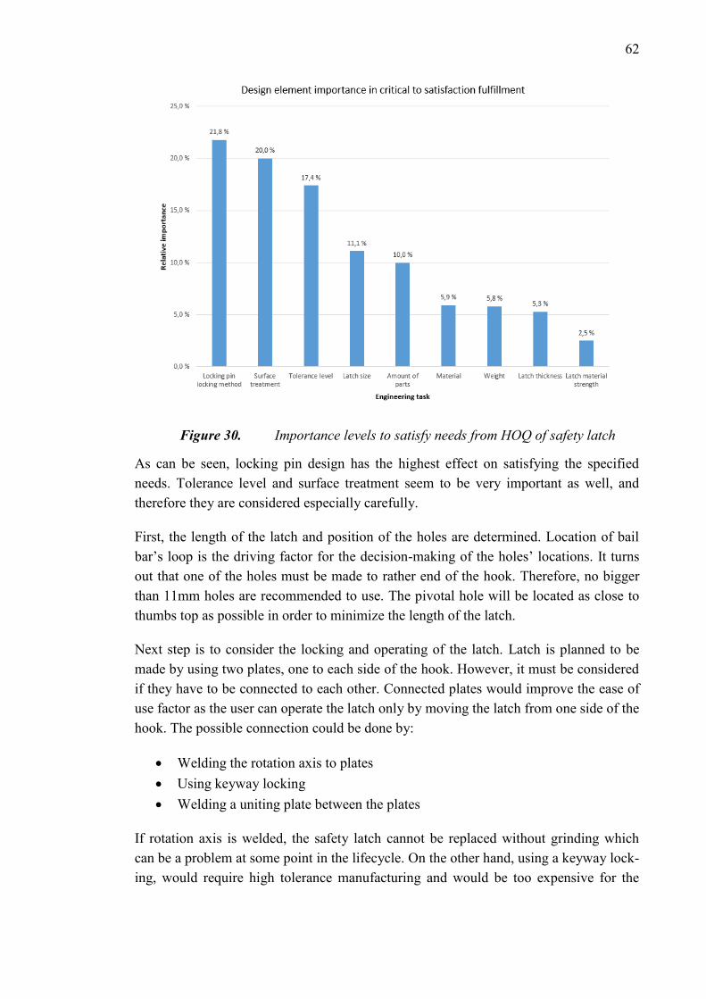
62
Figure 30. Importance levels to satisfy needs from HOQ of safety latch
As can be seen, locking pin design has the highest effect on satisfying the specified
needs. Tolerance level and surface treatment seem to be very important as well, and
therefore they are considered especially carefully.
First, the length of the latch and position of the holes are determined. Location of bail
bar’s loop is the driving factor for the decision-making of the holes’ locations. It turns
out that one of the holes must be made to rather end of the hook. Therefore, no bigger
than 11mm holes are recommended to use. The pivotal hole will be located as close to
thumbs top as possible in order to minimize the length of the latch.
Next step is to consider the locking and operating of the latch. Latch is planned to be
made by using two plates, one to each side of the hook. However, it must be considered
if they have to be connected to each other. Connected plates would improve the ease of
use factor as the user can operate the latch only by moving the latch from one side of the
hook. The possible connection could be done by:
Welding the rotation axis to plates
Using keyway locking
Welding a uniting plate between the plates
If rotation axis is welded, the safety latch cannot be replaced without grinding which
can be a problem at some point in the lifecycle. On the other hand, using a keyway lock-
ing, would require high tolerance manufacturing and would be too expensive for the

63
purposes. The last way would be to weld a uniting plate between the latches. However,
that would require making a groove to the hook, which is not desired option.
Since none of the above-mentioned options seems to be a viable option in order to con-
nect latches, separate latches have to be considered. The only issue is that now the user
would need to move the latch separately on both sides, which lowers the ease of use
factor. On the other hand, it is not such a time consuming or tricky task to do. Accord-
ing to the estimations, individually moving latches would save a lot of costs, which
drives us to select not connected latches at the expense of ease of use.
After the geometry of the latch is roughly known, we can start figuring out how the
locking would be done. There are three simple and possible ways to use:
Bolt locking
A shaft that is locked with snap lock pin on the other side
A shaft which can be locked from the same side as pushed in
The easiest way would be to use a normal bolt to lock the latches. However, it is not
very professional or convenient way since bolt cannot tighten up without tools, and gets
easily lost. On the other hand, the bolt could be replaced with a shaft that is locked with
a locking pin from the other side. The third option is to create a system where a shaft is
used but the system could be locked from the same side of the hook as operator stands.
In the figure 31 can be seen a draft design of a safety latch. The latch can be operated
from one side of the hook and the locking pin does not cause any collision with the cur-
rent latch shape when the latch is not in use.
Figure 31. Selected safety latch concept
The surface treatment of the safety latch was forbidden to be shiny. Therefore, a green
passivated electrogalvanized zinc treatment was chosen to be used. Painting was not
desired as it would wear off very quickly due to the contacting faces. In the literature for
atmospheric zinc corrosion rates from 0,13µm/year to 13 µm/year are reported. For ex-
ample, in Helsinki the rate is 1,3µm/year [29]. On the other hand, in Spain, a 20-year
service life would be achieved in a rural environment by using the coating thickness
specified by the company’s standard [30].

64
According to the information, it is hard to say if the used zinc layer is enough to last the
20 year life cycle requirement. Therefore, tolerances are adjusted so that the rust will
not jam the structure and latch will remain serviceable even if it rusts.
6.2 Ratchet mounting
According to the current design analysis carried out in the chapter 5.2.4, a ratchet can-
not absorb the ADR forces. It has been identified that easiest way to fix this is to in-
crease the angle of the ratchet vertically. Angle can be increased by lowering the ratch-
et’s lower mounting point by around 60mm. New mounting point is determined to be at
the same line with the lift frame, which means it is moved forward.
The mounting point can be made in many ways. Drivers for mounting point ADR forces
and cost efficiency. Cost efficient solution is a concept where amount of welding and
the number of items is low. According to the drivers, the possibility of using bolt
mounting is studied. However, it is noticed that a hydraulic pipe goes inside the com-
pression frame and makes bolt mounting hard to make. The connection to compression
frame shall be made therefore by welding.
Concepts for ratchet’s lower mounting:
U-profile welded to compression frame
L-plate and straight plate
Truck mounting bracket’s plate extended + L-plate
U-profile concept’s significant benefit is that it is very cost-efficient. The number of
items is very low and manufacturing easy, which makes the concept cheap. However,
strength-wise, it is not very viable option. Bends lower the strength of the structure and
make the welding hard when the profile is positioned to the same level with compres-
sion frame’s profile at the top.
The second, L-plate concept seems very viable strength and -cost -wise. The concept
requires only two plates and welding is quite easy to compression frame in this option.
The strength of this concept can be improved by having a wider top plate. Force is quite
high to the lower mounting, which is why third concept is created. The third concept is
the same as second apart from that the top plate is replaced with an extended truck
mounting bracket’s top plate. This will improve the bending stiffness and reduces the
number of parts.
In the figure 32 can be seen the FEM calculation results of the ratchet mounting concept
when the force of load case 4 is applied. Calculations reveal that there is a critical area
at L-plates lower welding area. High stresses are highest at the welds seam and exceed
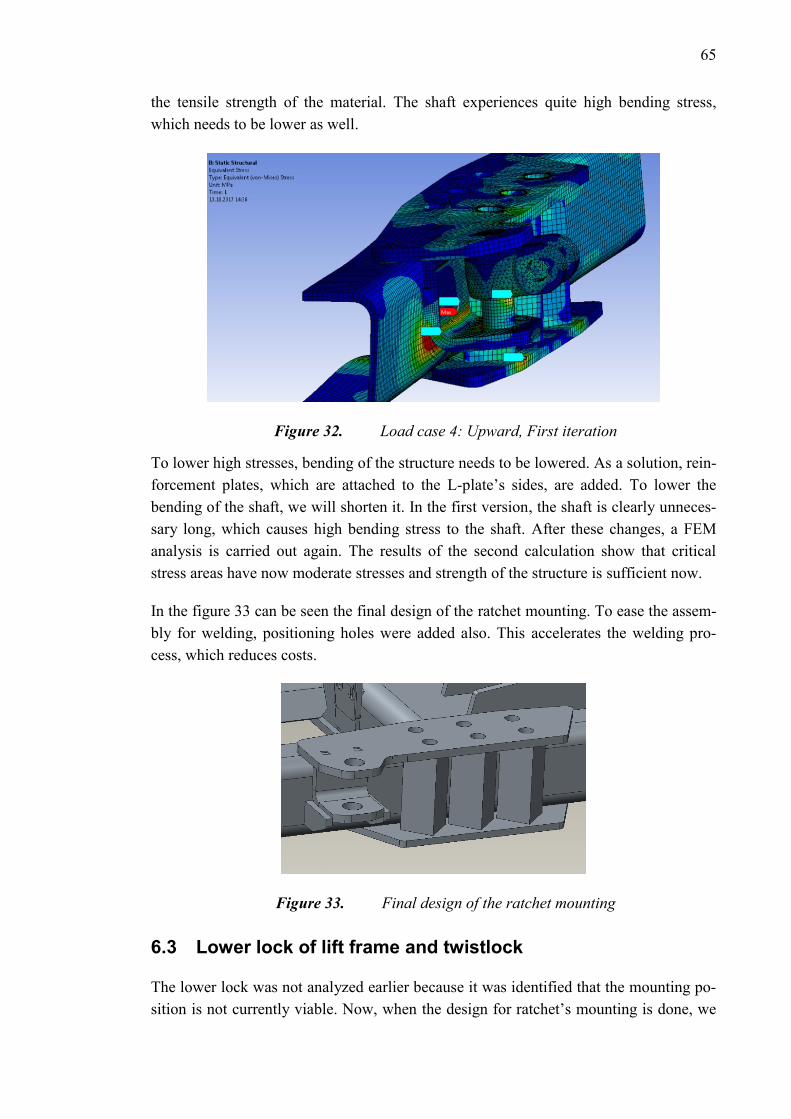
65
the tensile strength of the material. The shaft experiences quite high bending stress,
which needs to be lower as well.
Figure 32. Load case 4: Upward, First iteration
To lower high stresses, bending of the structure needs to be lowered. As a solution, rein-
forcement plates, which are attached to the L-plate’s sides, are added. To lower the
bending of the shaft, we will shorten it. In the first version, the shaft is clearly unneces-
sary long, which causes high bending stress to the shaft. After these changes, a FEM
analysis is carried out again. The results of the second calculation show that critical
stress areas have now moderate stresses and strength of the structure is sufficient now.
In the figure 33 can be seen the final design of the ratchet mounting. To ease the assem-
bly for welding, positioning holes were added also. This accelerates the welding pro-
cess, which reduces costs.
Figure 33. Final design of the ratchet mounting
6.3 Lower lock of lift frame and twistlock
The lower lock was not analyzed earlier because it was identified that the mounting po-
sition is not currently viable. Now, when the design for ratchet’s mounting is done, we
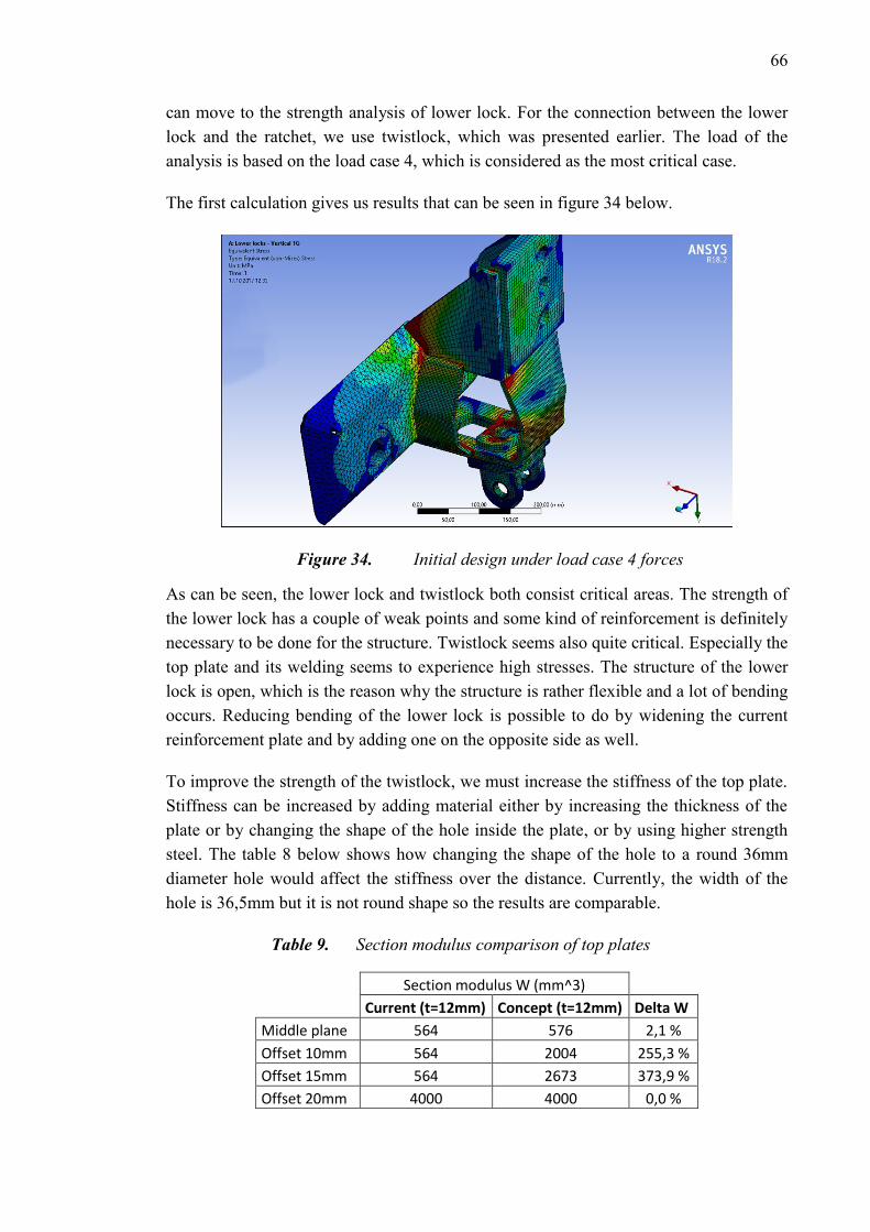
66
can move to the strength analysis of lower lock. For the connection between the lower
lock and the ratchet, we use twistlock, which was presented earlier. The load of the
analysis is based on the load case 4, which is considered as the most critical case.
The first calculation gives us results that can be seen in figure 34 below.
Figure 34. Initial design under load case 4 forces
As can be seen, the lower lock and twistlock both consist critical areas. The strength of
the lower lock has a couple of weak points and some kind of reinforcement is definitely
necessary to be done for the structure. Twistlock seems also quite critical. Especially the
top plate and its welding seems to experience high stresses. The structure of the lower
lock is open, which is the reason why the structure is rather flexible and a lot of bending
occurs. Reducing bending of the lower lock is possible to do by widening the current
reinforcement plate and by adding one on the opposite side as well.
To improve the strength of the twistlock, we must increase the stiffness of the top plate.
Stiffness can be increased by adding material either by increasing the thickness of the
plate or by changing the shape of the hole inside the plate, or by using higher strength
steel. The table 8 below shows how changing the shape of the hole to a round 36mm
diameter hole would affect the stiffness over the distance. Currently, the width of the
hole is 36,5mm but it is not round shape so the results are comparable.
Table 9. Section modulus comparison of top plates
Section modulus W (mm^3)
Current (t=12mm) Concept (t=12mm) Delta W
Middle plane 564 576 2,1 %
Offset 10mm 564 2004 255,3 %
Offset 15mm 564 2673 373,9 %
Offset 20mm 4000 4000 0,0 %
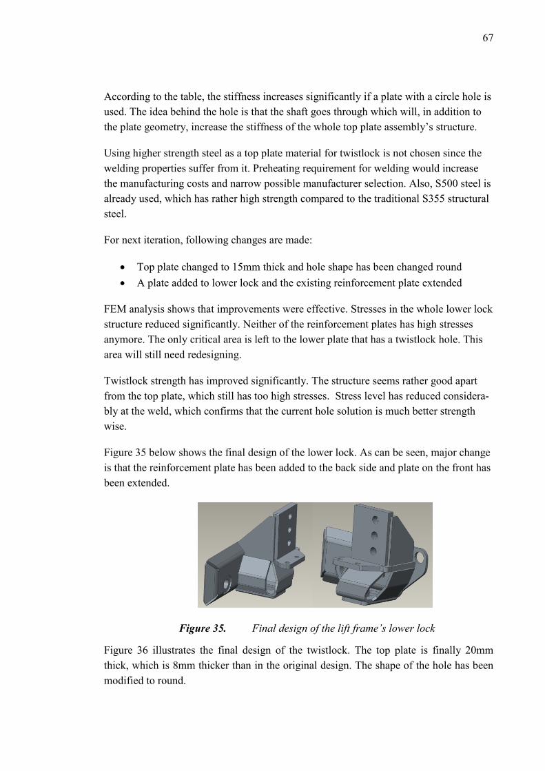
67
According to the table, the stiffness increases significantly if a plate with a circle hole is
used. The idea behind the hole is that the shaft goes through which will, in addition to
the plate geometry, increase the stiffness of the whole top plate assembly’s structure.
Using higher strength steel as a top plate material for twistlock is not chosen since the
welding properties suffer from it. Preheating requirement for welding would increase
the manufacturing costs and narrow possible manufacturer selection. Also, S500 steel is
already used, which has rather high strength compared to the traditional S355 structural
steel.
For next iteration, following changes are made:
Top plate changed to 15mm thick and hole shape has been changed round
A plate added to lower lock and the existing reinforcement plate extended
FEM analysis shows that improvements were effective. Stresses in the whole lower lock
structure reduced significantly. Neither of the reinforcement plates has high stresses
anymore. The only critical area is left to the lower plate that has a twistlock hole. This
area will still need redesigning.
Twistlock strength has improved significantly. The structure seems rather good apart
from the top plate, which still has too high stresses. Stress level has reduced considera-
bly at the weld, which confirms that the current hole solution is much better strength
wise.
Figure 35 below shows the final design of the lower lock. As can be seen, major change
is that the reinforcement plate has been added to the back side and plate on the front has
been extended.
Figure 35. Final design of the lift frame’s lower lock
Figure 36 illustrates the final design of the twistlock. The top plate is finally 20mm
thick, which is 8mm thicker than in the original design. The shape of the hole has been
modified to round.

68
Figure 36. Final design of the twistlock
With this design, the twistlock has adequate strength and is strong enough to absorb
loads required by the ADR.
6.4 Truck mounting bracket and DIN lock
The rear truck mounting bracket was replaced with a new one, which is now at the same
level with the bracket in the front. The design is already in use in another variant of
DROPS. The most critical load cases for the din locks are load case 6 and 8, which are
the 2G forward and 1G sideward. According to the FE analysis, the structure is capable
of absorbing the forces in both load cases but plastic deformation is expected in the bolt,
which is most rear and in the mounting plate. In figure 37 can be seen the FE analysis of
the structure. Detailed view reveals that in one of the bolts the stress level exceeds the
yield strength of it. According to the linear analysis tensile strength is exceeded only
locally and not over the thickness of the bolt. For more detailed stress calculation, a
nonlinear analysis would be required.
Figure 37. Load case 6: 2G forward
Even though plastic deformation is expected, the structure is capable of absorbing the
force. According to the linear analysis, it can be said that the stress level will not exceed

69
the tensile stress over the thickness and the structure will be capable of absorbing the
force. In the previous analysis, the U-beam was experiencing high stress as well, now it
seems that the stress level is moderate in the U-beam and no actions are required con-
cerning it. Figure 38 shows the new structure of the truck mounting plate.
Figure 38. New mounting bracket

70
7. REVIEW OF RESULTS
As the result of product development process, the hooklift is now ADR compliant, it has
a safety latch and it is interchangeable with the older DROPS hooklifts and CHUs. ADR
affected the most to the design and it can be considered as the biggest driver behind the
improvements. Overall, the product development process succeeded pretty well. New
design solutions fulfilled the product requirements quite well and the final design solu-
tions seemed viable. Validation of the design is not completely done yet and so it re-
mains as a task for the future.
New design was made to the following objects:
Lower locks of the lift frame
Twistlock
Ratchet mounting
Safety latch
Truck mounting bracket
Lower locks of the lift frame were reinforced and the biggest change was that a rein-
forcement plate was added to the structure. Reinforcement plate made the structure
closed, which improved significantly the strength of the structure. However, the closed
structure worsened the accessibility to weld all the plates from inside as well. Cost wise,
any significant changes did not occur.
The design of the ratchet mounting bracket changed significantly. The new bracket has
a new approach compared to the old ones in a way that it is not detachable. By not hav-
ing a detachable bracket, it was possible to minimize the number of parts to the mini-
mum. In addition, design parameters were able to be reduced. Cost wise this is a very
efficient way since the manufacturing cost is rather low and it enables easier retro fitting
possibility.
The strength analysis of twistlock revealed issues in the original design of the lock. Ac-
cording to the FE analysis, high stresses occur in the top plate and in the welds of the
structure. In order to reduce the stresses in the welds enough, the shape of the holes
where welds are was changed to a normal hole. The shaft was extended so that it went
all the way through to the holes and welds were moved that way away from the area that
experienced most bending. The top plate thickness was also increased to increase the
section modulus.

71
The outcome of the actions resulted in a viable solution. The strength of the structure
increased significantly and it can now handle the ADR loads. The weight of the new
twistlock increased by 35%, which was not desired aspect but necessary since the inter-
changeability was retained by using these twistlocks. Weldability of the structure suf-
fered slightly from the modification. The weld around the shaft and the weld for the
“legs” of the twistlock will clash a little. In addition, the shaft reduces the space that is
available for fitting the electrode near the seam.
The complete ratchet module overall was replaced with a new one. According to the
estimations, the cost compared to the former module would lower by 25%. The ratchet
module includes a new ratchet, a new lower mounting bracket, a new twistlock interface
and a new ratchet holder during the transportation mode.
The new safety latch design ended up to be simple and manually operated as desired.
The concept got overall the highest score in AHP since it did not have low points on any
criterions. Therefore, it was logical to select it as the concept for further development.
Other potential concepts for the safety latch were a detachable latch, gravity assisted
latch, a securing chain or cable and pneumatic safety latch. The pneumatic latch got
second highest points. The reason is that ease of use was ranked quite high and the
pneumatic latch was clearly all the way easiest to use compared to any other latch.
However, the pneumatic latch was excessively too expensive to implement and design,
which was finally the reason that it did not come into consideration selecting it.
The securing cable or chain concept got also quite high total points. However, it got
unnecessary high points since it was so much cheaper and simpler than any other con-
cept. Nevertheless, since the safety of it was not that good it came not in consideration
to select. In addition, the concept would not look very professional. Professional look
could have been also one of the criterions in the AHP. It would have then described
better the desired traits from the latch.
For the selected concept, any extra features were not designed as the main drivers be-
hind the design was low costs. Modifications to the current hook were avoided as much
as possible as well. Finally, only three holes were added to the hook for the safety latch
mounting and any shape modifications were not made. A prototype from the concept
was build and it was tested in use. Testing confirmed that concept was a viable solution.
However, according to prototype testing, it is hard to know how corrosion will effect on
the structure over the time. The structure has rather loose tolerances, which should help
that the latch is not so sensitive to jamming due the corrosion, but on the other hand,
loose tolerances can make the structure more fragile and sensitive to hits. Especially the
other side latch will be more sensitive to collision because of the loose tolerances.
Nonetheless, the testing showed the latch does not experience such hits and collisions
that often that it should be an aspect to be concerned of.

72
For the future, customer feedback should be gathered of the latch. Especially the lock-
ing system behavior over the time and hits is an interesting an aspect. Other future tasks
remain to be validation of manufacturability of each improvement and validation of
them working in the real environment. For example, the ratchet mounting bracket that is
used while ratchets are not in use has not been tested in the real environment. It is not
completely clear if the ratchet can be operated conveniently with the current dimension-
ing. A possible improvement to the ratchet would to replace the tightening rod of the
ratchet to a different kind of rod. For space saving purposes, a rod that goes through to
the center tube and can be switched from the side to another would be convenient solu-
tion to be used.

73
8. CONCLUSIONS
The objectives of this thesis were to fulfill product requirements and to clarify the
meaning of ADR in context of hooklifts from the mechanical point of view. The product
requirements in the framework of this thesis consisted of three basic requirements: in-
terchangeability, ADR compliancy and safety latch. In order to fulfill them and to per-
form efficient product development, Design for Six Sigma principles were chosen to be
used to achieve it.
ADR regulations required clarification as there had been several different interpretations
of them over the years in the case company. The ADR regulations does not directly re-
fer in any section to hooklifts but only to twistlock secured demountables or fixed type
tanks and their fastenings. Therefore, there had been several interpretations of the re-
quirements. During the research, it was found that Norway had noticed the same ambi-
guity concerning hooklifts and the government of Norway had made a proposal to clari-
fy the ADR.
The product development work in this thesis consist of four parts. First, the product re-
quirements that create the framework for the design were determined. In the second
phase the current state of design were analyzed. Target of the analysis was to find out
whether the current state of design fulfilled the product requirements or not. After that,
improvements were done to the elements that required it and evaluation was carried out
again. After requirements were fulfilled, optimization was carried out to the design ele-
ments to create even better quality and cost-efficient design.
DFSS principles and tools could be utilized to support the product development process
quite well. All the product requirements and their relation to design tasks were modelled
by using QFD to analyze their relationships. The relative importance levels of design
tasks could be evaluated with the QFD and the most significant and critical design ele-
ments could be identified. In safety latch concept design phase, innovating tools such as
brainstorming and benchmarking were used in order to create safety latch concepts.
Finally, the decisions were made with assistance of AHP, which provided rational com-
parison results according to the determined criterion. After selection, the chosen concept
was transferred to real design and prototype testing and optimization actions were car-
ried out.
All in all, the product requirements within the framework were fulfilled well. Facelifted
MPH165 is now mechanically ADR compliant, interchangeable with the older equip-
ment and equipped with a safety latch. Since complete validation of the design could

74
not been carried out within the time frame, it remains as a future task. Feedback from
the manufacturers and customers will provide the final evaluation of the design quality.
In the future, DFSS tools such as QFD could be utilized in the upcoming projects in the
case company. By utilizing QFD, potential to better customer satisfaction and more ef-
ficient usage of resources could be achieved.

75
REFERENCES
[1] ADR Agreement, Economic Commission for Europe Inland Transport Commit-
tee, 2017, 1280 p. Available at:
https://www.unece.org/fileadmin/DAM/trans/danger/publi/adr/adr2017/ADR2017
e_web.pdf
[2] Series 1 freight containers – Corner and intermediate fittings – Specifications,
International Organization for Standardization, SS-ISO 1161 (2nd ed.), 2016, pp.
1-24.
[3] Series 1 freight containers -- Classification, dimensions and ratings, International
Organization for Standardization. SS-ISO 668 (3rd ed.), 2013, pp. 1-22.
[4] World Shipping Council. Container Supply Review (Report). May 2011, Availa-
ble at: http://www.worldshipping.org/public-
statements/2011_container_supply_review_final.pdf. Accessed 12.9.2017.
[5] Yang K, El-Haik B. Design for six sigma: a roadmap for product development.
2nd ed. New York, McGraw-Hill, 2009, 741 p.
[6] MkIV Generic Installation Manual, Item number: A4420020, Issue A, Partek
Cargotec Ltd, 1999, 70 p.
[7] Report of the Working party on its 102nd session, ECE/TRANS/WP.15/237. 8-11
May 2017, Geneva, UNECE, 2017, 31 p. Available at:
https://www.unece.org/fileadmin/DAM/trans/doc/2017/dgwp15/ECE-TRANS-
WP15-237e.pdf
[8] Proposal for amendment for MEGCs and tank-containers in Chapter 6.8. ECE-
TRANS-WP15-100-GE-inf27, 9-13 May 2016, Geneva, UNECE, 2016, 2 p.
[9] Report of the Joint Meeting of the RID Committee of Experts and the Working
Party on the Transport of Dangerous Goods on its autumn 2015 session ECE
TRANS WP15 AC1 140a2e, 15-25 September 2015, Geneva, UNECE, 2016, 9 p.
[10] Cargotec QPR system. Available at: Available for internal personnel only. Ac-
cessed 22.11.2017.
[11] House of Quality, A dictionary of Business and Management (6 ed.), Oxford Uni-
versity Press, 2016.

76
[12] QFD Institute. Available at: http://www.qfdi.org. Accessed 22/11, 2017.
[13] Mehrzad T. Introduction to Finite Element Method. : Mercury Learning and In-
formation, 2016.
[14] Öchsner A, Merkel M. One-Dimensional Finite Elements: An Introduction to the
FE Method. 2013th ed. Berlin, Heidelberg: Springer Berlin Heidelberg, 2013.
[15] Chowdhury S, Books24x7 I. Design for Six Sigma: the revolutionary process for
achieving extraordinary profits. Chicago: Dearborn Trade Pub, 2002.
[16] Geng H. Manufacturing engineering handbook, McGraw-Hill, 2015.
[17] Hyysalo S. Käyttäjä tuotekehityksessä: tieto, tutkimus, menetelmät. 2. uud. laitos
ed. Helsinki: Taideteollinen korkeakoulu, 2009.
[18] Ulrich KT, Eppinger SD. Product design and development. 5th ed. New York,
NY: McGraw-Hill Irwin, 2012.
[19] Vaidya OS, Kumar S. Analytic hierarchy process: An overview of applications.
Eur J Oper Res 2006, 169(1) pp. 1-29.
[20] Toimintatutkimus, Available at:
https://koppa.jyu.fi/avoimet/hum/menetelmapolkuja/menetelmapolku/tutkimusstra
tegiat/toimintatutkimus, Accessed 27.12.2017.
[21] Kuula, Arja, Toimintatutkimus. Luku 5.4. kokonaisuudesta Saaranen-Kauppinen,
Anita ja Puusniekka, Anna, KvaliMOTV - Menetelmäopetuksen tietovaranto.
Tampere: Yhteiskuntatieteellinen tietoarkisto, 2006.
[22] Fredriksson, B., “Holistic Systems Engineering in Product Development,” The
Saab-Scania Griffin, 1994, Saab-Scania, AB, Linkoping, Sweden, Nov. 1994.
[23] Labro E. Is a focus on collaborative product development warranted from a cost
commitment perspective? Supply Chain Management: An International Journal,
2006, 11(6), pp. 503-509.
[24] THIELMANN WEW Container Systems GmbH. Available at: http://www.army-
technology.com/contractors/logistics/thielmann-wew/attachment/thielmann-
wew1/. Accessed 28.12.2017.
[25] Vasell T, Vuolle M, Petrulaitiene V, Nenonen S, Jylhä T. Identifying and measur-
ing customer value - case multi-locational worker. 2016.

77
[26] Holt R, Barnes C. Towards an integrated approach to "Design for X": an agenda
for decision-based DFX research. Research in Engineering Design, 2010, 21(2),
123 p.
[27] Isixsigma.com. DFMEA. Available
at: https://www.isixsigma.com/dictionary/dfmea/. Accessed 3.1.2018.
[28] Liu, Zeng, Research on Conceptual Design Method for Marine Power Plant Based
on QFD, IEEE, 1, 2012, pp. 246-249.
[29] American Galvanizers Association. Atmospheric corrosion data. Available at:
https://www.galvanizeit.org/hot-dip-galvanizing/how-long-does-hdg-last/in-the-
atmosphere/time-to-first-maintenance/atmospheric-corrosion-data. Accessed 12.1.
2018.
[30] de la Fuente D, Castaño JG, Morcillo M. Long-term atmospheric corrosion of
zinc. Corrosion Science 2007, March 2007, 49(3), pp. 1420-1436.
[31] AHP calculation software by CGI, Available at: http://www.isc.senshu-
u.ac.jp/~thc0456/EAHP/AHPweb.html, Accessed 12.12.2017.
[32] Amendments to ADR 9.7.3 concerning fastening requirements, ECE-TRANS-
WP.15/2017/7, 20. February 2017, UNECE, Available at:
https://www.google.fi/url?sa=t&rct=j&q=&esrc=s&source=web&cd=1&cad=rja
&uact=8&ved=0ahUKEwi-
xtrS5dnYAhUEApoKHYGjAPYQFggoMAA&url=https%3A%2F%2Fwww.unec
e.org%2Ffileadmin%2FDAM%2Ftrans%2Fdoc%2F2017%2Fdgwp15%2FECE-
TRANS-WP15-2017-07e.docx&usg=AOvVaw0zKIz32E70efLX-xtDG4LX
[33] Multilift Commander – ISO Container Handling Unit for hooklift, Available at:
https://www.youtube.com/watch?v=38H_L70R3_k, Accessed 19.1.2018.
[34] Demountable load carrying platforms (DLCP/Flatracks), STANAG 2413 (4th ed.),
Brussels, NATO Standardization Agency, 2009, 19 p.
[35] Taguchi, G., Introduction to Quality Engineering, UNIPUB/Kraus International
Publications, White Plains, N.Y. 1986.
[36] Altshuller, G. S., Creativity as Exact Science, Gordon & Breach, New York.
1988.
[37] Suh, N. P., The Principles of Design, Oxford University Press, New York. 1990.

78
APPENDIX A: HOUSE OF QUALITY

79
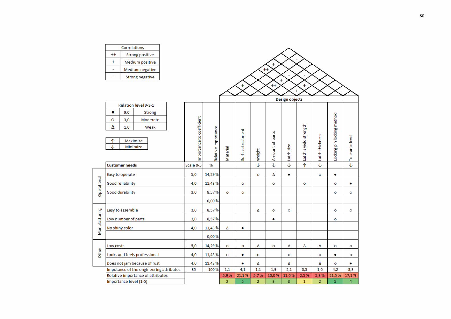
80
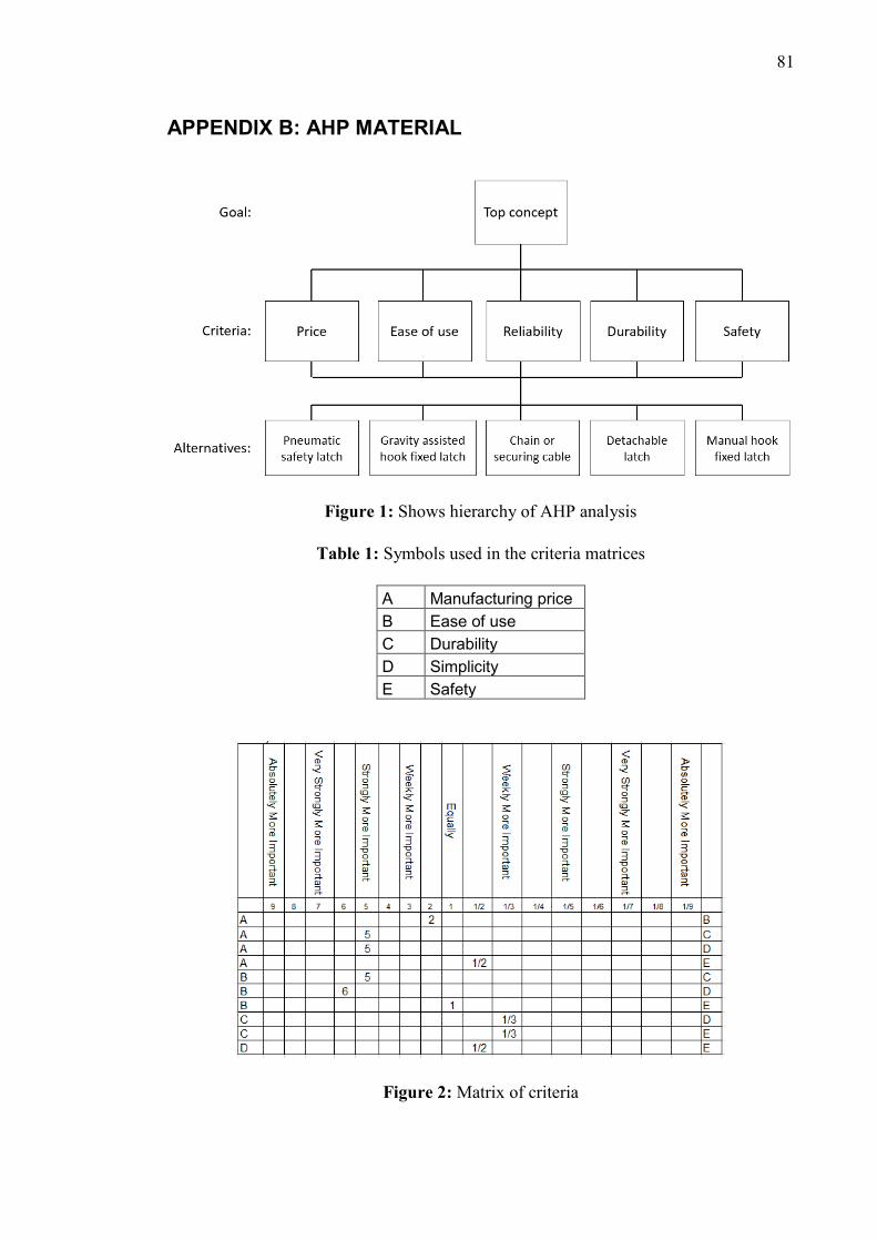
81
APPENDIX B: AHP MATERIAL
Figure 1: Shows hierarchy of AHP analysis
Table 1: Symbols used in the criteria matrices
A Manufacturing price
B Ease of use
C Durability
D Simplicity
E Safety
Figure 2: Matrix of criteria

82
Table 2: Symbols that are used in the figure 3-7
A Pneumatic latch
B Gravity assisted
C Chain or securing cable
D Detachable latch
E Manual hook fixed latch
Figure 3: Matrix of manufacturing price
Figure 4: Matrix of Ease of use

83
Figure 5: Matrix of durability
Figure 6: Matrix of simplicity

84
Figure 7: Matrix of safety
Table 3: Weights of the criterion and alternatives
Table 4: Global evaluation results of the weights

85
Figure 8: Global evaluation results graphically presented