Embed Size (px)
Citation preview

Series CHKD/CHKG
JIS Standard Compact Hydraulic CylinderCompact Hydraulic Cylinder
Series CHKG
Nominal pressure: 16 MPaBore size (mm): 20, 25, 32, 40, 50, 63, 80, 100
Series CHKD
Nominal pressure: 10 MPaBore size (mm): 20, 25, 32, 40, 50, 63, 80, 100
183
CHQ
CHK�
CHN
CHM
CHS�
CH2�
CHA
D-�
RelatedEquipment
CHKD
CHDKD
32 30
32 30 M9BWWith auto switch(built-in magnet)
Cylinder stroke (mm)Refer to the standard stroke table on page 185.
Nil
TNRc
NPT
Port thread type
Made to orderspecificationsFor details, refer to page 185.
Built-in Magnet Cylinder Model If a built-in magnet cylinder without auto switch is required, there is no need to enter the symbol for the auto switch.(Example) CHDKDB50-100
B
B
Female threadMale thread
NilM
Rod end thread type
Bore size 20 25 32 40 50 63 80100
20 mm 25 mm 32 mm 40 mm 50 mm 63 mm 80 mm100 mm
∗ Select applicable auto switch models from the table below.
Without auto switchNil
Auto switch type
2 pcs.1 pc.
"n" pcs.
NilSn
Number of auto switches
Mounting bracket style
B
L
LB
LD
Basic style
Foot style
—
Symbol Style Port position Note)
Right
Left
Foot bracket
Top
∗ Lead wire length symbols: 0.5 m ······ Nil (Example) M9NW
∗ For ø32 to ø100, there are applicable auto switches other than listed. Refer to page 193 for details.∗ For details about auto switches with pre-wired connector, refer to pages 389 and 390.∗ Cylinders with auto switch will be shipped together with the auto switch and auto switch mounting bracket (ø32 to ø50) (not assembled).
∗ Solid state auto switches marked "�" are produced upon receipt of order.∗ The D-A9 model cannot be mounted on ø50.
Type Electricalentry
Pre-wiredconnector
Ind
ica
tor
ligh
t
3-wire (NPN)
2-wire
Load voltage Auto switch modelElectrical entry direction
—100 V
100 V or less
ACDC
Lead wire length (m)
0.5(Nil)
1(M)
3(L)
5(Z)
Applicable load
5 V
12 V
—
24 VYes
No
Yes
3-wire (NPN)3-wire (PNP)
2-wire3-wire (NPN)3-wire (PNP)
2-wire3-wire (NPN)3-wire (PNP)
2-wire
IC circuit
IC circuit
Ree
dsw
itch
So
lid s
tate
sw
itch
∗A96V∗A93V∗A90V
∗A96∗A93∗A90
Water resistant(2-color display)
Diagnostic indication(2-color display)
RelayPLC
RelayPLC24 V
Grommet
Grommet
Wiring(output)
Special function
Perpendicular In-line
—
5 V, 12 V
12 V
5 V, 12 V
12 V
5 V, 12 V
12 V
M9NVM9PVM9BV
M9NWVM9PWVM9BWVM9NAVM9PAVM9BAV
M9NM9PM9B
M9NWM9PWM9BWM9NAM9PAM9BA
IC circuit
IC circuit
IC circuit
Applicable Auto Switches: Refer to pages 347 to 406 for further details on each auto switch.
How to Order
With Auto Switch
1 m ······ M (Example) M9NWM3 m ······ L (Example) M9NWL5 m ······ Z (Example) M9NWZ
Note) Indicates the relative position of the foot bracket and port, as seen from the rod side.
∗ Rod end thread type is an optional product. (Re-fer to page 186).
JIS Standard Compact Hydraulic Cylinder
ø20, ø25, ø32, ø40, ø50, ø63, ø80, ø100Series CH �KD
10 MPa
184

Action
Fluid
Nominal pressure
Proof pressure
Maximum allowable pressure
Minimum operating pressure
Ambient and fluid temperature
Piston speed
Cushion
Rod end thread
Stroke length tolerance
Mounting style
Bore size (mm)
Specifications
Double acting/Single rod
Hydraulic fluid
10 MPa
15 MPa
13 MPa
0.3 MPa
Without auto switch: –10° to 80°C
With auto switch: –10° to 60°C
8 to 100 mm/s
None
Female thread, Male thread
mm
Basic style (through hole), Foot style
Note) Refer to page 134 for definitions of terms related to pressure.
+0.8 0
Manufacture of Intermediate Stroke Cylinders[XC63] (Built-in spacer type)
Intermediate strokes in 5 mm increments can be manufactured by installing spacers inside standard stroke cylinders.55, 60, 65 and 70 mm stroke cylinders have the same overall length as a 75 mm stroke cylinder, and 80, 85, 90 and 95 mm stroke cylinders have the same length as a 100 mm stroke cylinder.Refer to the Made to Order Specifications on page 196 for the ordering procedure.
JIS symbol
Standard Strokes
Bore size(mm)20, 25
3240, 50, 6380, 100
Stroke(mm)
5 10 15 20 25 30 35 40 45 50
55 60 65 70
75 100
80 85 90 95
Intermediate stroke [XC63](Built-in spacer type)
Intermediate stroke [XC63](Built-in spacer type)
�: Standard stroke (dedicated cylinder tube)�: Intermediate stroke XC63 (built-in spacer type)
Made to order specifications(For details, refer to pages 195 to 197)
Symbol Specifications
Compatible with CHQHB series (14 MPa)Intermediate stroke type (Built-in spacer type)With air release valve
-XC61-XC63-XC64
20 25 32 40 50 63 80 100
∗ Consult with SMC.
Hydraulic Fluid Compatibility
Standard mineral hydraulic fluid
W/O hydraulic fluid
O/W hydraulic fluid
Water/Glycol hydraulic fluid
Phosphate hydraulic fluid
Compatibility
Compatible
Compatible
Compatible
∗Not compatible
Hydraulic fluid
Made toOrder
JIS Standard Compact Hydraulic Cylinder: 10 MPa Series CH�KD
185
CHQ
CHK�
CHN
CHM
CHS�
CH2�
CHA
D-�
RelatedEquipment
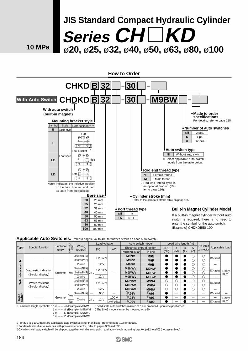
Theoretical Output
Bore size(mm)
Rod size(mm)
Operatingdirection
Piston area(mm2)
OUT
IN
OUT
IN
OUT
IN
OUT
IN
OUT
IN
OUT
IN
OUT
IN
OUT
IN
20
25
32
40
50
63
80
100
12
14
18
22.4
28
35.5
45
56
314
201
490
336
804
549
1256
862
1963
1347
3117
2127
5026
3436
7853
5390
3.5
1099
704
1715
1176
2814
1922
4396
3017
6871
4715
10910
7445
17591
12026
27486
18865
10
3140
2010
4900
3360
8040
5490
12560
8620
19630
13470
31170
21270
50260
34360
78530
53900
Operating pressure (MPa)
7
2198
1407
3430
2352
5628
3843
8792
6034
13741
9429
21819
14889
35182
24052
54971
37730
Unit: N
Theoretical output (N) = Pressure (MPa) x Piston area (mm2)
Optional Parts(mm)
Part no.
NTH-020
NTH-025
NTH-032
NTH-040
NTH-050
NTH-060
NTH-080
NTH-100
NTH-125
Bore size (mm)
20
20
25
32
40
50
63
80
100
B
13
17
19
22
27
32
41
55
70
C
15
19.6
21.9
25.4
31.2
37
47.3
63.5
80.8
D
12.5
16.5
18
21
26
31
40
54
69
H
5
6
7
10
12
14
17
20
26
d
M8 x 1
M10 x 1.25
M12 x 1.25
M16 x 1.5
M20 x 1.5
M24 x 1.5
M30 x 1.5
M39 x 1.5
M48 x 1.5
Rod end nut
30° d
H B
CøD
Mass
Bore size(mm)
20253240506380
100
Standard stroke (mm)
5 218 299 515 7291065177332166142
10 240 327 558 7841139188233796384
15 262 355 601 8391213199135426626
20 282 383 644 8941287210038686868
25 304 411 687 9491361220940317110
30 326 439 73010041435231841947352
35 348 467 77310591509242743577594
40 370 495 81611141583253645207836
45 392 523 85911691657264546838078
50 414 551 90212241731275448468320
75——
111714992101329956619530
100——
1332 1774 2471 3844 647610740
Unit: g
Bore size(mm)
Standard stroke (mm)
465570880
1375220038456555
11355
20253240506380
100
Unit: gCH�KDL/Foot style
CH�KDB/Basic style
490600925
1435228039606725
11610
510630970
1495236040756900
11865
535660
10151550243541957235
12120
560690
10601610251543107410
12375
580720
11001670259544257580
12630
605750
11501725267545457755
12885
630780
11901785275546607930
13140
650810
12351845283547758100
13400
675840
12801900291048958275
13655
——
——
15052195331054759150
14930
1730248537056060
1001016210
5 10 15 20 25 30 35 40 45 50 75 100
Note) There may be a slight difference between the part numbers and the corresponding bore size.
Series CH�KD
186

Mounting bolt
Mounting Bolts for CH�KDB
Through hole type mounting bolts are available.How to order: Add "Bolt" in front of the bolts to be used.
Example: M8 x 80L 4 pcs.
CH�KDB20
CH�KDB25
CH�KDB32
CH�KDB40
CModel D D 55
60
65
70
75
80
85
90
95
100
55
60
65
70
75
80
85
90
95
100
60
65
70
75
80
85
90
95
100
105
130
65
70
75
80
85
90
95
100
105
110
135
160
Mounting bolt
M5 x 55L
x 60L
x 65L
x 70L
x 75L
x 80L
x 85L
x 90L
x 95L
x 100L
M5 x 55L
x 60L
x 65L
x 70L
x 75L
x 80L
x 85L
x 90L
x 95L
x 100L
M6 x 60L
x 65L
x 70L
x 75L
x 80L
x 85L
x 90L
x 95L
x 100L
x 105L
x 130L
M8 x 65L
x 70L
x 75L
x 80L
x 85L
x 90L
x 95L
x 100L
x 105L
x 110L
x 135L
x 160L
70
75
80
85
90
95
100
105
110
115
140
165
75
80
85
90
95
100
105
110
115
120
145
170
90
95
100
105
110
115
120
125
130
135
160
185
110
115
120
125
130
135
140
145
150
155
180
205
M10 x 70L
x 75L
x 80L
x 85L
x 90L
x 95L
x 100L
x 105L
x 110L
x 115L
x 140L
x 165L
M12 x 75L
x 80L
x 85L
x 90L
x 95L
x 100L
x 105L
x 110L
x 115L
x 120L
x 145L
x 170L
M14 x 90L
x 95L
x 100L
x 105L
x 110L
x 115L
x 120L
x 125L
x 130L
x 135L
x 160L
x 185L
M16 x 110L
x 115L
x 120L
x 125L
x 130L
x 135L
x 140L
x 145L
x 150L
x 155L
x 180L
x 205L
DC
Mounting bolt diagram
12.4
10.4
10.5
13.5
CH�KDB50
CH�KDB63
CH�KDB80
CH�KDB100
CModel Mounting bolt
15.8
16
22.2
26.5
-5 (M)
-10 (M)
-15 (M)
-20 (M)
-25 (M)
-30 (M)
-35 (M)
-40 (M)
-45 (M)
-50 (M)
-75 (M)
-100 (M)
-5 (M)
-10 (M)
-15 (M)
-20 (M)
-25 (M)
-30 (M)
-35 (M)
-40 (M)
-45 (M)
-50 (M)
-75 (M)
-100 (M)
-5 (M)
-10 (M)
-15 (M)
-20 (M)
-25 (M)
-30 (M)
-35 (M)
-40 (M)
-45 (M)
-50 (M)
-75 (M)
-100 (M)
-5 (M)
-10 (M)
-15 (M)
-20 (M)
-25 (M)
-30 (M)
-35 (M)
-40 (M)
-45 (M)
-50 (M)
-5 (M)
-10 (M)
-15 (M)
-20 (M)
-25 (M)
-30 (M)
-35 (M)
-40 (M)
-45 (M)
-50 (M)
-5 (M)
-10 (M)
-15 (M)
-20 (M)
-25 (M)
-30 (M)
-35 (M)
-40 (M)
-45 (M)
-50 (M)
-75 (M)
-5 (M)
-10 (M)
-15 (M)
-20 (M)
-25 (M)
-30 (M)
-35 (M)
-40 (M)
-45 (M)
-50 (M)
-75 (M)
-100 (M)
-5 (M)
-10 (M)
-15 (M)
-20 (M)
-25 (M)
-30 (M)
-35 (M)
-40 (M)
-45 (M)
-50 (M)
-75 (M)
-100 (M)
JIS Standard Compact Hydraulic Cylinder: 10 MPa Series CH�KD
187
CHQ
CHK�
CHN
CHM
CHS�
CH2�
CHA
D-�
RelatedEquipment
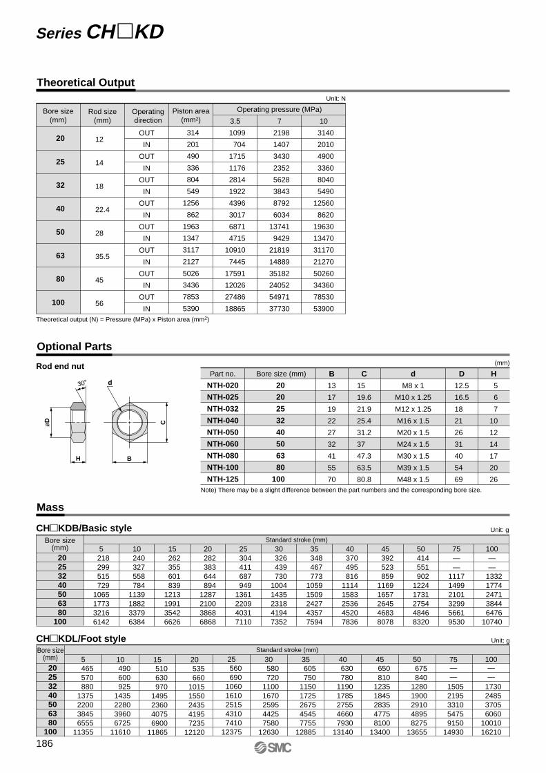
Water Resistant Type
A special scraper is installed on the basic cylinder to prevent liquid in the surrounding area from entering the cylinder.It can be used in environments where exposure to machine tool coolants is likely, as well as in environments where water spray and splashing is frequent, such as in food processing machinery and car washing equipment.
CHDKDB Bore size Port thread type Rod end thread typeStroke M9�A(V)LR
NBR Seal (Nitrile rubber)FKM Seal (Fluororubber)
RV
Water resistant cylinder Water resistant solid state auto switchwith 2-color display
Refer to page 185 for specifications.
5. Since Series CH�KDB does not have an air release plug, release air from other components (e.g. from piping, etc.) as well.
6. Do not use two cylinders facing one another hori-zontally or vertically in such a way that their piston rods strike each other.
7. When the cylinder head side contains hydraulic flu-id or is in a normally pressurized condition, the ap-plied load must not be allowed to strike the piston rod end. Avoid such applications.
8. When mounting the cylinder body with mounting bolts, use tightening torques in the table at left as a guide.
Usage
Caution
Specific Product Precautions
Body mounting bolt tightening torquesBore size (mm) Mounting bolt size
M5M5M6M8M10M12M14M16
Tightening torque (N·m) 2.5 4 7 16 30 40 70 100
20253240506380
100
1. Use hexagon socket head cap screws (JISB1176, strength class 10.9 or higher) for cylinder mounting.
2. Since a lateral load (eccentric load) cannot be ap-plied to the piston rod, build the mounting jig in such a way that a lateral load will not be applied to the piston rod.
3. Make sure that the interlocking length of the rod end thread (male or female thread) and the mount-ing material is at least 80% of the thread diameter.
4. When operating a cylinder for the first time, be sure to release the air inside the cylinder and the piping. When the air release is complete, operate the cylin-der at reduced pressure, then gradually increase it to the normal operating pressure.
Magnetic body (steel plate, etc.)
ø20 to ø100M9�A(V)L
With auto switch(Built-in magnet)
Be sure to read before handling. Refer to front matters 30 and 31 for Safety Instructions, and pages 134 to 142 for precautions for hydraulic cylinder and auto switch.
Consult with SMC when using a cylinder in close proximity to a mag-netic body (including proximity on any side) as shown in the figure be-low, as the operation of auto switches may become unstable.
Series CH�KD
188

Construction
Parts List Replacement Parts/Seal KitNo.
1
2
3
4
5
6
7
8
9
10
11
12
13
14
20
25
32
40
50
63
80
100
Bore size (mm) Seal kit no.
CHKD20-PS
CHKD25-PS
CHKD32-PS
CHKD40-PS
CHKD50-PS
CHKD63-PS
CHKD80-PS
CHKD100-PS
ContentDescription
Rod cover
Head cover
Cylinder tube
Piston rod
Piston
Bushing
Back-up ring
Magnet
Magnet plate
Scraper
Rod seal
Piston seal
Tube gasket
Piston gasket
Material
Aluminum alloy
Aluminum alloy
Aluminum alloy
Stainless steel
Copper alloy
Resin
—
Stainless steel
NBR
Note
Black anodized
Black anodized
Hard anodized
Hard chromiumelectroplated
With auto switch only
With auto switch only
Nos. u, !0, !1, !2, and!3 from the chart at left
ø32 to ø100
Without auto switch
ø20 to ø25
r !0!1 q y!3 oi !4 !2u t e w
Stainless steel
Carbon steel
ø20, ø25
ø32 to ø100
∗ Seal kit consists of items u, !0, !1, !2 and !3, and can be ordered by using the seal kit number for each bore size.
∗ Special tools are necessary for disassembly. Contact SMC for recommended tool designs and dimensions. Furthermore, ø80 and ø100 are tightened with a large tightening torque, so disassembly will be difficult. Contact SMC if disas-sembly is required.
JIS Standard Compact Hydraulic Cylinder: 10 MPa Series CH�KD
189
CHQ
CHK�
CHN
CHM
CHS�
CH2�
CHA
D-�
RelatedEquipment

g
33
36
45
50
56
68
87
111
h
76
81
96
105
116
135
165
207
(mm)
Dimensions
4 x øK through8 x øL counter bore
F with effective thread depth G F with effective thread depth G
4 x øK through8 x øL counter bore
E
�J
�M
E
�J
�M
øD
H
C B + Stroke h + Stroke
A + Stroke
R
R
Q
c
ab
ge
Q
2 x Rc P
Width across flats f
Rod endmale thread
CH�KDB20, 25 CH�KDB32 to 100
Bore size (mm)
20
25
32
40
50
63
80
100
Bore size (mm)
20
25
32
40
50
63
80
100
A
51
53
61
65
71
80
95
122
B
43
45
51
55
60
67
78
96
C
8
8
10
10
11
13
17
26
D
12
14
18
22.4
28
35.5
45
56
E
10
12
14
19
24
30
41
50
F
M8 x 1.25
M10 x 1.5
M12 x 1.75
M16 x 2
M20 x 2.5
M27 x 3
M30 x 3.5
M39 x 4
G
10
12
15
20
24
33
36
45
H
6
6
7
7
8
9
14
21
J
30
36
47
52
58
69
86
106
K
5.5
5.5
6.6
9
11
13
15
17
L
9.5 depth 5.4
9.5 depth 5.4
11 depth 6.5
14 depth 8.6
17.5 depth 10.8
20 depth 13
23 depth 15.2
26 depth 17.5
a
12.5
15.5
22
27
32
42
57
72
b
15
18
25
30
35
45
60
75
c
M10 x 1.25
M12 x 1.25
M16 x 1.5
M20 x 1.5
M24 x 1.5
M30 x 1.5
M39 x 1.5
M48 x 1.5
e
6
6
7
7
8
9
14
21
f
10
12
14
19
24
30
41
50
h
66
71
86
95
106
125
155
197
g
23
26
35
40
46
58
77
101
M
43
49
63
71
81
97
117
142
P
1/8
1/8
1/4
1/4
1/4
1/4
3/8
3/8
Q
16.5
17
19.5
20.5
22
25.5
30
36
R
6
8
10
10
10
10
15
15
Note 1) Body dimensions are the same with or without auto switches.
(mm)
(mm)Rod end male threads Water resistant type
20
25
32
40
50
63
80
100
A
61
63
71
75
81
90
105
132
Bore size (mm) B
43
45
51
55
60
67
78
96
C
18
18
20
20
21
23
27
36
N
26.5
30
38
45
55
66
86
104
S
6
6
7
7
7
7
7
7
g
h + Stroke
S
C B + Stroke
A + Stroke
øN
Rod endmale thread
Water resistant type
Basic style/CH�KDB
Series CH�KD
190

Dimensions
ZZ + Stroke
RR
h + Stroke
geb
a
CH
øD
A + Stroke
Z + Stroke Y1SS
B + Stroke X1X1
�M
LH
LT
LW
E
LXBB
ø32 to ø100
ø20 to ø25
2 x Rc P
Rod endmale thread
cWidth across flats f
4 x øCD
F with effective thread depth G
Bore size(mm)
20253240506380
100
A B BB C F LCD D E G H K LH LT LX
(mm)
76
78
86
98
111
130
151
179
43
45
51
55
60
67
78
96
70
76
94
108
126
146
172
208
18
18
19
23
27
33
38
43
M8 x 1.25
M10 x 1.5
M12 x 1.75
M16 x 2
M20 x 2.5
M27 x 3
M30 x 3.5
M39 x 4
9.5 depth 5.4
9.5 depth 5.4
11 depth 6.5
14 depth 8.6
17.5 depth 10.8
20 depth 13
23 depth 15.2
26 depth 17.5
6.6
6.6
9
11
14
16
18
22
12
14
18
22.4
28
35.5
45
56
10
12
14
19
24
30
41
50
10
12
15
20
24
33
36
45
6
6
7
7
8
9
14
21
5.5
5.5
6.6
9
11
13
15
17
23
26
33
37
43
52
63
76
15
15
16
20
24
30
35
40
58
64
79
90
104
121
144
174
Bore size(mm)
20253240506380
100
LW M P Q R X1 Y1 Z ZZ
44.5
50.5
64.5
72.5
83.5
100.5
121.5
147
43
49
63
71
81
97
117
142
1/8
1/8
1/4
1/4
1/4
1/4
3/8
3/8
16.5
17
19.5
20.5
22
25.5
30
36
6
8
10
10
10
10
15
15
15
15
16
20
24
30
35
40
SS
10.5
10.5
11
13
15
18
20.5
23
7.5
7.5
8
10
12
15
17.5
20
58
60
67
75
84
97
113
136
73
75
83
95
108
127
148
176
(mm)
(mm)
a
12.5
15.5
22
27
32
42
57
72
b
15
18
25
30
35
45
60
75
e
6
6
7
7
8
9
14
21
f
10
12
14
19
24
30
41
50
g
33
36
44
53
62
78
98
118
h
91
96
111
128
146
175
221
254
c
M10 x 1.25
M12 x 1.25
M16 x 1.5
M20 x 1.5
M24 x 1.5
M30 x 1.5
M39 x 1.5
M48 x 1.5
Bore size(mm)
20253240506380
100
Rod end male threadsNote 1) Body dimensions are the same with or without auto switches.
Foot style/CH�KDL
2 x øK through4 x øL counter bore
JIS Standard Compact Hydraulic Cylinder: 10 MPa Series CH�KD
191
CHQ
CHK�
CHN
CHM
CHS�
CH2�
CHA
D-�
RelatedEquipment

Auto Switches: Proper Mounting Positions and Mounting Heights for Stroke End Detection
D-M9�D-M9�WD-M9�ALD-A9�
D-Y5�D-Y7�D-Y7�WD-Y7BALD-Z7�D-Z80
D-M9�VD-M9�WVD-M9�AVLD-A9�V
D-M9�D-M9�WD-M9�ALD-A9�
D-M9�VD-M9�WVD-M9�AVLD-Y6�D-Y7�VD-Y7�WVD-A9�V
ø20, ø25 ø32 to ø100
Auto Switch SpecificationsSeries CH�KD
Refer to pages 347 to 406 for detailed specifications.
A
B
A
BA
B
A
B= MA= MA
20253240506380
100
D-M9�/M9�V D-M9�W/M9�WVD-M9�AL/M9�AVL
D-Y59�/Y69�D-Y7�/Y7�VD-Y7�W/Y7�WVD-Y7BAL
D-A9�/A9�V D-Z7�/Z80
A12 13 15 17 18 21.523.531.5
B19 20 21.523.527.531 40 49.5
A——
10 12 13 16.518.526.5
B——
16.518.522.526 35 44.5
A8 9
11 13 —
17.519.527.5
B15 16 17.519.5—
27 36 45.5
A——
10 12 13 16.518.526.5
B——
16.518.522.526 35 44.5
Auto Switch Proper Mounting Positions
Bore size(mm)
(mm)Solid state auto switch Reed auto switch
20253240506380
100
D-M9�D-M9�WD-M9�ALD-A9�
D-M9�VD-M9�WVD-M9�AVL
D-A9�V
D-Y59�D-Y7PD-Y7�WD-Y7BALD-Z7�D-Z80
D-Y69�D-Y7PVD-Y7�WV
U21.524.531.535.540.5 Note)
48.558.571
U28 30 34 38.544.553 63.576
U25.527.531.536 — Note)
50.561 73.5
U——
31.535.540.548.558.571
U——
31.535.541.550 60.573
Auto Switch Mounting Heights
Bore size(mm)
(mm)
Note 1) D-A9�/A9�V models cannot be mounted on ø50.Note 2) Adjust the auto switch after confirming the operating conditions in the actual setting.
Note 1) D-A9�/A9�V models cannot be mounted on ø50.
192

Auto Switch Mounting Brackets: Part Nos.
Minimum Auto Switch Mounting Stroke
∗ Solid state auto switches are also available with pre-wired connector. Refer to pages 389 and 390 for details.∗ Normally closed (N.C. = b contact), solid state auto switches (D-F9G, F9H, Y7G, Y7H) are also available. For details, refer to pages
365 and 367.
For ø32 to ø100, besides the models listed in "How to Order," the following auto switches are applicable.Refer to pages 347 to 406 for detailed auto switch specifications.
Auto switch type Part no. FeaturesElectrical entry
D-Y69A, Y69B, Y7PV
D-Y7NWV, Y7PWV, Y7BWV
D-Y59A, Y59B, Y7P
D-Y7NW, Y7PW, Y7BW
D-Y7BAL
D-Z73, Z76
D-Z80
—
Diagnostic indication (2-color display)
—
Diagnostic indication (2-color display)
Water resistant (2-color display)
—
Without indicator light
Grommet (perpendicular)
Grommet (in-line)
Grommet (in-line)
Solid state
Reed
Operating Range
Auto switch modelsBore size
20
12
—
25
11
—
32
9
9.5
40
9.5
11
50
—
12
63
11.5
14
80
15
16
100
17
20
4.5 4.5 4 7 5 5.5 7.5 11
— — 8 9.5 11.5 11.5 16 17
D-A9�/A9�VD-Z7�/Z80
(mm)
1 pc.2 pcs.
D-M9�D-M9�VD-Y59�D-Y69�D-Y7PD-Y7PV
D-A9�D-A9�VD-Z7�D-Z80
D-Y7�WD-Y7�WV
D-M9�WD-M9�WVD-M9�ALD-M9�AVL
D-Y7BAL
5
5
5
10
10
10
10
15
15
15
Auto SwitchMountingNumber
(mm)
Auto switch modelsBore size (mm)
ø32 to ø100
BMG2-012
D-M9�/M9�VD-M9�W/M9�WVD-M9�AL/M9�AVLD-A9�/A9�V
Note 1) D-A9�/A9�V models cannot be mounted on ø50.
∗ Examples of D-A9�(V), M9�(V), M9�W(V), M9�A(V)L models mounted on CHKD.
BMG2-012
D-M9�/M9�VD-M9�W/M9�WVD-M9�AL/M9�AVL
D-Y59�/Y69�D-Y7�/Y7�VD-Y7�W/Y7�WVD-Y7BAL
Note) D-A9�/A9�V models cannot be mounted on ø50 ∗ Since this is a guideline including hysteresis, not meant to be guaranteed. (Assuming approximately ±30% dispersion.)
There may be the case it will vary substantially depending on an ambient environment.
JIS Standard Compact Hydraulic Cylinder: 10 MPa Series CH�KD
193
CHQ
CHK�
CHN
CHM
CHS�
CH2�
CHA
D-�
RelatedEquipment
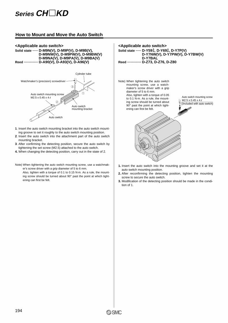
How to Mount and Move the Auto Switch
1. Insert the auto switch into the mounting groove and set it at the auto switch mounting position.
2. After reconfirming the detecting position, tighten the mounting screw to secure the auto switch.
3. Modification of the detecting position should be made in the condi-tion of 1.
Note) When tightening the auto switch mounting screw, use a watch-maker's screw driver with a grip diameter of 5 to 6 mm.Also, tighten with a torque of 0.05 to 0.1 N·m. As a rule, the mount-ing screw should be turned about 90° past the point at which tight-ening can first be felt.
<Applicable auto switch>Solid state ······ D-Y59 , D-Y69 , D-Y7P(V)
D-Y7NW(V), D-Y7PW(V), D-Y7BW(V)D-Y7BAL
Reed ··············· D-Z73, D-Z76, D-Z80
AB
AB
<Applicable auto switch>Solid state ······ D-M9N(V), D-M9P(V), D-M9B(V),
D-M9NW(V), D-M9PW(V), D-M9BW(V)D-M9NA(V), D-M9PA(V), D-M9BA(V)
Reed ··············· D-A90(V), D-A93(V), D-A96(V)
Cylinder tube
Watchmaker’s (precision) screwdriver
Auto switchmounting bracket
Auto switch
Auto switch mounting screwM2.5 x 0.45 x 4 l
w
e
q
1. Insert the auto switch mounting bracket into the auto switch mount-ing groove to set it roughly to the auto switch mounting position.
2. Insert the auto switch into the attachment part of the auto switch mounting bracket.
3. After confirming the detecting position, secure the auto switch by tightening the set screw (M2.5) attached to the auto switch.
4. When changing the detecting position, carry out in the state of 2.
Note) When tightening the auto switch mounting screw, use a watchmak-er's screw driver with a grip diameter of 5 to 6 mm.Also, tighten with a torque of 0.1 to 0.15 N·m. As a rule, the mount-ing screw should be turned about 90° past the point at which tight-ening can first be felt.
Auto switch mounting screwM2.5 x 0.45 x 4 l(Included with auto switch)
Series CH�KD
194
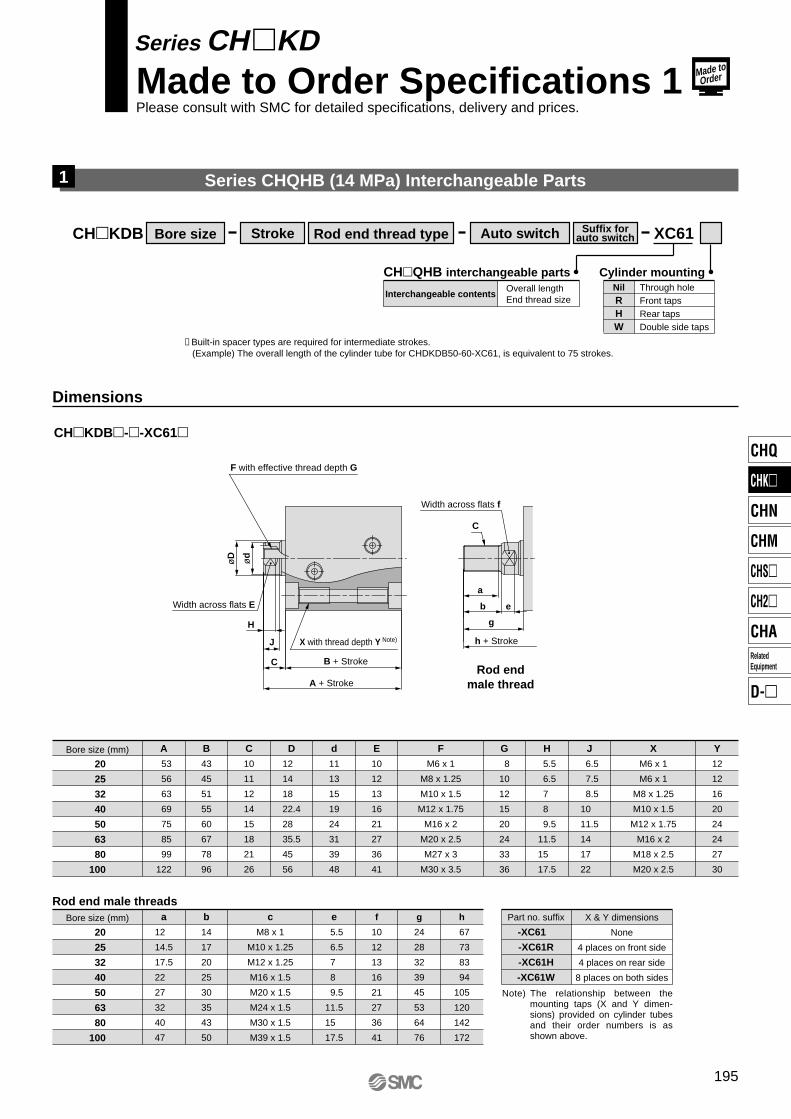
Series CHQHB (14 MPa) Interchangeable Parts
CH�KDB Bore size Rod end thread type Auto switch Suffix forauto switch XC61Stroke
Overall lengthEnd thread size
Interchangeable contents
CH�QHB interchangeable partsThrough holeFront tapsRear tapsDouble side taps
NilRHW
Cylinder mounting
Dimensions
CH�KDB�-�-XC61�
Bore size (mm)
F with effective thread depth G
X with thread depth Y Note)
B + Stroke
h + Stroke
A + Stroke
Width across flats E
Width across flats f
20
25
32
40
50
63
80
100
A
53
56
63
69
75
85
99
122
B
43
45
51
55
60
67
78
96
C
10
11
12
14
15
18
21
26
d
11
13
15
19
24
31
39
48
D
12
14
18
22.4
28
35.5
45
56
E
10
12
13
16
21
27
36
41
G
8
10
12
15
20
24
33
36
H
5.5
6.5
7
8
9.5
11.5
15
17.5
J
6.5
7.5
8.5
10
11.5
14
17
22
Y
12
12
16
20
24
24
27
30
F
M6 x 1
M8 x 1.25
M10 x 1.5
M12 x 1.75
M16 x 2
M20 x 2.5
M27 x 3
M30 x 3.5
X
M6 x 1
M6 x 1
M8 x 1.25
M10 x 1.5
M12 x 1.75
M16 x 2
M18 x 2.5
M20 x 2.5
Bore size (mm)
20
25
32
40
50
63
80
100
a
12
14.5
17.5
22
27
32
40
47
b
14
17
20
25
30
35
43
50
c
M8 x 1
M10 x 1.25
M12 x 1.25
M16 x 1.5
M20 x 1.5
M24 x 1.5
M30 x 1.5
M39 x 1.5
e
5.5
6.5
7
8
9.5
11.5
15
17.5
f
10
12
13
16
21
27
36
41
g
24
28
32
39
45
53
64
76
h
67
73
83
94
105
120
142
172
Part no. suffix
-XC61
-XC61R
-XC61H
-XC61W
X & Y dimensions
None
4 places on front side
4 places on rear side
8 places on both sides
Note) The relationship between the mounting taps (X and Y dimen-sions) provided on cylinder tubes and their order numbers is as shown above.
H
øD ød
J
C
C
a
b
g
e
Rod endmale thread
1
Rod end male threads
∗ Built-in spacer types are required for intermediate strokes. (Example) The overall length of the cylinder tube for CHDKDB50-60-XC61, is equivalent to 75 strokes.
195
Series CH�KD Made to Order Specifications 1Please consult with SMC for detailed specifications, delivery and prices.
Made toOrder
CHQ
CHK�
CHN
CHM
CHS�
CH2�
CHA
D-�
RelatedEquipment

Intermediate strokes in 5mm increments can be manufactured by installing spacers inside standard stroke cylinders.
CH�KDB XC63
Applicable cylinder tubeFor 75 mm stroke
For 75 mm stroke
For 100 mm stroke
Applicable stroke55, 60, 65, 70
55, 60, 65, 70
80, 85, 90, 95
Bore size (mm) 32 40 50 63 80100
Intermediate stroke
CH�KDL XC63
CH�KDB�-�-XC63
StrokeBore size(mm)
32
40
50
63
80
100
A
136
140
146
155
170
197
A
—
165
171
180
195
222
B
126
130
135
142
153
171
B
—
155
160
167
178
196
55, 60, 65, 70 80, 85, 90, 95
B
A Note) Dimensions other than those highlighted above are standard.
Intermediate Stroke Type (Built-in spacer type)2
Dimensions
CH�KDL�-�-XC63
StrokeBore size(mm)
32
40
50
63
80
100
LA
161
173
186
205
226
254
LA
—
198
211
230
251
279
B
126
130
135
142
153
171
LZ
142
150
159
172
188
211
B
—
155
160
167
178
196
LZ
—
175
184
197
213
236
55, 60, 65, 70 80, 85, 90, 95
B
LA
LZ
Bore size Rod end thread type Auto switch Suffix forauto switchStroke
Bore size Rod end thread type Auto switch Suffix forauto switchStroke
Series CH�KD Made to Order Specifications 2Please consult with SMC for detailed specifications, delivery and prices.
Made toOrder
196

Air release valves are provided on cylinder tube surfaces machined for ports.
CH�KDB XC64
With air release valve
CH�KDL XC64
CH�KDB�-�-XC64
Bore size (mm)
20
25
32
40
50
63
80
100
A
16.5
17
19.5
20.5
22
25.5
30
36
C
7
8
10
10
10
10
15
15
B
14.5
15
17
17.5
19.5
22
26.5
33
Note) Dimensions other than those highlighted above are standard.
A
B
C
CWith Air Release Valve3
Dimensions
CH�KDL�-�-XC64
B
A
C
CBore size Rod end thread type Auto switch Suffix for
auto switchStroke
Bore size Rod end thread type Auto switch Suffix forauto switchStroke
Series CH�KD Made to Order Specifications 3Please consult with SMC for detailed specifications, delivery and prices.
Made toOrder
197
CHQ
CHK�
CHN
CHM
CHS�
CH2�
CHA
D-�
RelatedEquipment
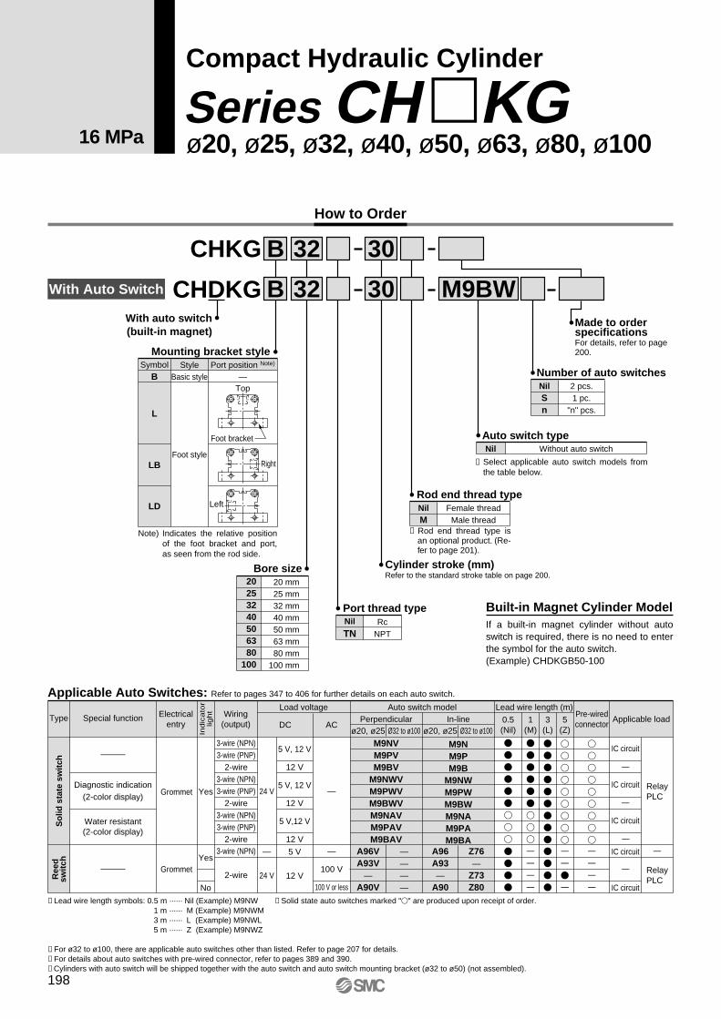
Cylinder stroke (mm)Refer to the standard stroke table on page 200.
CHKG
CHDKG
32 30
M9BWWith auto switch(built-in magnet)
Bore size 20 25 32 40 50 63 80100
20 mm 25 mm 32 mm 40 mm 50 mm 63 mm 80 mm100 mm
Female threadMale thread
NilM
Rod end thread type
2 pcs.1 pc.
"n" pcs.
NilSn
Number of auto switches
Made to orderspecificationsFor details, refer to page 200.
Nil
TNRc
NPT
Port thread type Built-in Magnet Cylinder ModelIf a built-in magnet cylinder without auto switch is required, there is no need to enter the symbol for the auto switch.(Example) CHDKGB50-100
Mounting bracket style
B
L
LB
LD
Foot style
—Symbol Port position Note)
Foot bracket
Right
Top
Left
B
∗ Select applicable auto switch models from the table below.
Without auto switchNilAuto switch type
∗ Rod end thread type is an optional product. (Re-fer to page 201).
32 30B
∗ Solid state auto switches marked "�" are produced upon receipt of order.
How to Order
With Auto Switch
Type Electricalentry
Pre-wiredconnector
Indic
ato
rlig
ht
3-wire (NPN)
2-wire
Load voltage Auto switch model
—
100 V
100 V or less
ACDC
Lead wire length (m)
0.5(Nil)
1(M)
3(L)
5(Z)
Applicable load
5 V
12 V
—
24 V
Yes
No
Yes
3-wire (NPN)3-wire (PNP)
2-wire3-wire (NPN)3-wire (PNP)
2-wire3-wire (NPN)3-wire (PNP)
2-wire
Ree
dsw
itch
So
lid s
tate
sw
itch
A96VA93V
—A90V
————
A96A93—
A90
Z76—
Z73Z80
RelayPLC
RelayPLC
24 V
Grommet
Grommet
Wiring(output)
Perpendicularø20, ø25 Ø32 to ø100 ø20, ø25 Ø32 to ø100
In-line
—
5 V, 12 V
12 V
5 V, 12 V
12 V
5 V,12 V
12 V
M9NVM9PVM9BV
M9NWVM9PWVM9BWVM9NAVM9PAVM9BAV
M9NM9PM9B
M9NWM9PWM9BWM9NAM9PAM9BA
Applicable Auto Switches: Refer to pages 347 to 406 for further details on each auto switch.
Compact Hydraulic Cylinder
ø20, ø25, ø32, ø40, ø50, ø63, ø80, ø100Series CH �KG
16 MPa
Water resistant(2-color display)
Diagnostic indication(2-color display)
Special function
IC circuit
IC circuit
IC circuit
IC circuit
IC circuit
∗ Lead wire length symbols: 0.5 m ······ Nil (Example) M9NW
∗ For ø32 to ø100, there are applicable auto switches other than listed. Refer to page 207 for details.∗ For details about auto switches with pre-wired connector, refer to pages 389 and 390.∗ Cylinders with auto switch will be shipped together with the auto switch and auto switch mounting bracket (ø32 to ø50) (not assembled).
1 m ······ M (Example) M9NWM3 m ······ L (Example) M9NWL5 m ······ Z (Example) M9NWZ
StyleBasic style
Note) Indicates the relative position of the foot bracket and port, as seen from the rod side.
198

Action
Fluid
Nominal pressure
Proof pressure
Maximum allowable pressure
Minimum operating pressure
Ambient and fluid temperature
Piston speed
Cushion
Rod end thread
Stroke length tolerance
Mounting style
Bore size (mm)
Specifications
Standard Strokes
Double acting/Single rod type
Hydraulic fluid
16 MPa
24 MPa
16 MPa
0.3 MPa
Without auto switch: –10° to 80°C
With auto switch: –10° to 60°C
8 to 100 mm/s
None
Female thread, Male thread
mm
Basic style (through hole), Foot style
20 25 32 40 50 63 80 100
Note) Refer to page 134 for definitions of terms related to pressure.
+0.8 0
Bore size (mm)
20, 25
32
40, 50, 63, 80, 100
Standard strokes (mm)
5, 10, 15, 20, 25, 30, 35, 40, 45, 50, 75, 100
5, 10, 15, 20, 25, 30, 35, 40, 45, 50, 75, 100, 125, 150
5, 10, 15, 20, 25, 30, 35, 40, 45, 50, 75, 100, 125, 150, 175JIS symbol
Manufacture of Intermediate Stroke Cylinders[XC63] (Built-in spacer type)
Intermediate strokes in 5 mm increments can be manufactured by installing spacers inside standard stroke cylinders. 55, 60, 65 and 70 mm stroke cylinders have the same overall length as a 75 mm stroke cylinder, and 80, 85, 90 and 95 mm stroke cylinders have the same length as a 100 mm stroke cylinder. Refer to the Made to Order Specifications on page 211 for the ordering procedure.
Made to order specifications(For details, refer to pages 210 to 212)
Symbol Specifications
Compatible with series CHQHB series (14 MPa)Intermediate stroke type (Built-in spacer type)With air release valve
-XC62-XC63-XC64
∗ Consult with SMC.
Hydraulic Fluid Compatibility
Standard mineral hydraulic fluid
W/O hydraulic fluid
O/W hydraulic fluid
Water/Glycol hydraulic fluid
Phosphate hydraulic fluid
Compatibility
Compatible
Compatible
Compatible
∗Not compatible
Hydraulic fluid
Made toOrder
199
Compact Hydraulic Cylinder: 16 MPa Series CH�KG
CHQ
CHK�
CHN
CHM
CHS�
CH2�
CHA
D-�
RelatedEquipment

Theoretical Output
Bore size(mm)
Rod size(mm)
Operatingdirection
Piston area(mm2)
OUT
IN
OUT
IN
OUT
IN
OUT
IN
OUT
IN
OUT
IN
OUT
IN
OUT
IN
20
25
32
40
50
63
80
100
12
14
18
22.4
28
35.5
45
56
314
201
490
336
804
549
1256
862
1963
1347
3117
2127
5026
3436
7853
5390
3.5
1099
704
1715
1176
2814
1922
4396
3017
6871
4715
10910
7445
17591
12026
27486
18865
10
3140
2010
4900
3360
8040
5490
12560
8620
19630
13470
31170
21270
50260
34360
78530
53900
16
5024
3216
7840
5376
12864
8784
20096
13792
31408
21552
49872
34032
80416
54976
125648
86240
7
2198
1407
3430
2352
5628
3843
8792
6034
13741
9429
21819
14889
35182
24052
54971
37730
Unit: N
Theoretical output (N) = Pressure (MPa) x Piston area (mm2)
Operating pressure (MPa)
(mm)
Part no.
NTH-020
NTH-025
NTH-032
NTH-040
NTH-050
NTH-060
NTH-080
NTH-100
NTH-125
Bore size (mm)
20
20
25
32
40
50
63
80
100
B
13
17
19
22
27
32
41
55
70
C
15
19.6
21.9
25.4
31.2
37
47.3
63.5
80.8
D
12.5
16.5
18
21
26
31
40
54
69
H
5
6
7
10
12
14
17
20
26
d
M8 x 1
M10 x 1.25
M12 x 1.25
M16 x 1.5
M20 x 1.5
M24 x 1.5
M30 x 1.5
M39 x 1.5
M48 x 1.5
Optional Parts
Rod end nut
d
H B
CøD
30°
Mass
Bore size(mm)
20253240506380
100
Standard stroke (mm)5
221 312 581 9271351181338707188
10 242 339 625 9861430193640537457
15 263 366 66910451509205942367726
20 284 393 71311041588218244197995
25 305 420 75711631667230546028264
30 326 447 80112221746242847858533
35 347 474 84512811825255149688802
40 368 501 88913401904267451519071
45 389 528 93313991983279753349340
50 410 555 97714582062292055179609
75——
1197 1753 2457 3535 643210954
100——
1417 2048 2852 4150 734712299
Unit: g
Standard stroke (mm)
465585945
1580249539007225
12425
490610990
1645258040307420
12710
515640
10401705266541607615
12990
535670
10851770275042907805
13275
560700
11301830283544208000
13555
580725
11751895291545508195
13840
605755
12201955300046858385
14120
625785
12652015308548158580
14405
650815
13102080317049458775
14685
670840
13602140325550758965
14970
785985
15852455367557309935
16385
89011301815276540956380
1099017795
20253240506380
100
Unit: gCH�KGL/Foot style
CH�KGB/Basic style
5 10 15 20 25 30 35 40 45 50 75 100——
2045 3075 4515 70351187019210
125——
2270 3390 4935 76851283520625
150———
3700 5355 83401380022035
175Bore size
(mm)
Note) There may be a slight difference between the part numbers and the corresponding bore size.
200
Series CH�KG

Mounting bolt
Mounting Bolts for CH�KGB
55 60 65 70 75 80 85 90 95100125150 55 60 65 70 75 80 85 90 95100125150 65 70 75 80 85 90 95100105110135160185210 75 80 85 90 95100105110115120145170195220245
D DM5 x 55L x 60L x 65L x 70L x 75L x 80L x 85L x 90L x 95L x 100L x 125L x 150LM5 x 55L x 60L x 65L x 70L x 75L x 80L x 85L x 90L x 95L x 100L x 125L x 150LM6 x 65L x 70L x 75L x 80L x 85L x 90L x 95L x 100L x 105L x 110L x 135L x 160L x 185L x 210LM8 x 75L x 80L x 85L x 90L x 95L x 100L x 105L x 110L x 115L x 120L x 145L x 170L x 195L x 220L x 245L
80 85 90 95100105110115120125150175200225250 85 90 95100105110115120125130155180205230255100105110115120125130135140145170195220245270120125130135140145150155160165190215240265290
M10 x 80L x 85L x 90L x 95L x 100L x 105L x 110L x 115L x 120L x 125L x 150L x 175L x 200L x 225L x 250LM12 x 85L x 90L x 95L x 100L x 105L x 110L x 115L x 120L x 125L x 130L x 155L x 180L x 205L x 230L x 255LM14 x 100L x 105L x 110L x 115L x 120L x 125L x 130L x 135L x 140L x 145L x 170L x 195L x 220L x 245L x 270LM16 x 120L x 125L x 130L x 135L x 140L x 145L x 150L x 155L x 160L x 165L x 190L x 215L x 240L x 255L x 290L
DC
Mounting bolt diagramThrough hole type mounting bolts are available.How to order: Add "Bolt" in front of the bolts to be used.
Example: M8 x 80L 4 pcs.
CH�KGB20
CH�KGB25
CH�KGB32
CH�KGB40
CModel Mounting bolt
12.4
10.4
10.5
13.5
CH�KGB50
CH�KGB63
CH�KGB80
CH�KGB100
CModel Mounting bolt
15.5
16
22
26.5
-5 (M)-10 (M)-15 (M)-20 (M)-25 (M)-30 (M)-35 (M)-40 (M)-45 (M)-50 (M)-75 (M)-100 (M)-5 (M)-10 (M)-15 (M)-20 (M)-25 (M)-30 (M)-35 (M)-40 (M)-45 (M)-50 (M)-75 (M)-100 (M)-5 (M)-10 (M)-15 (M)-20 (M)-25 (M)-30 (M)-35 (M)-40 (M)-45 (M)-50 (M)-75 (M)-100 (M)-125 (M)-150 (M)-5 (M)-10 (M)-15 (M)-20 (M)-25 (M)-30 (M)-35 (M)-40 (M)-45 (M)-50 (M)-75 (M)-100 (M)-125 (M)-150 (M)-175 (M)
-5 (M)-10 (M)-15 (M)-20 (M)-25 (M)-30 (M)-35 (M)-40 (M)-45 (M)-50 (M)-75 (M)-100 (M)-125 (M)-150 (M)-175 (M)-5 (M)-10 (M)-15 (M)-20 (M)-25 (M)-30 (M)-35 (M)-40 (M)-45 (M)-50 (M)-75 (M)-100 (M)-125 (M)-150 (M)-175 (M)-5 (M)-10 (M)-15 (M)-20 (M)-25 (M)-30 (M)-35 (M)-40 (M)-45 (M)-50 (M)-75 (M)-100 (M)-125 (M)-150 (M)-175 (M)
-5 (M)-10 (M)-15 (M)-20 (M)-25 (M)-30 (M)-35 (M)-40 (M)-45 (M)-50 (M)-75 (M)-100 (M)-125 (M)-150 (M)-175 (M)
Compact Hydraulic Cylinder: 16 MPa Series CH�KG
201
CHQ
CHK�
CHN
CHM
CHS�
CH2�
CHA
D-�
RelatedEquipment
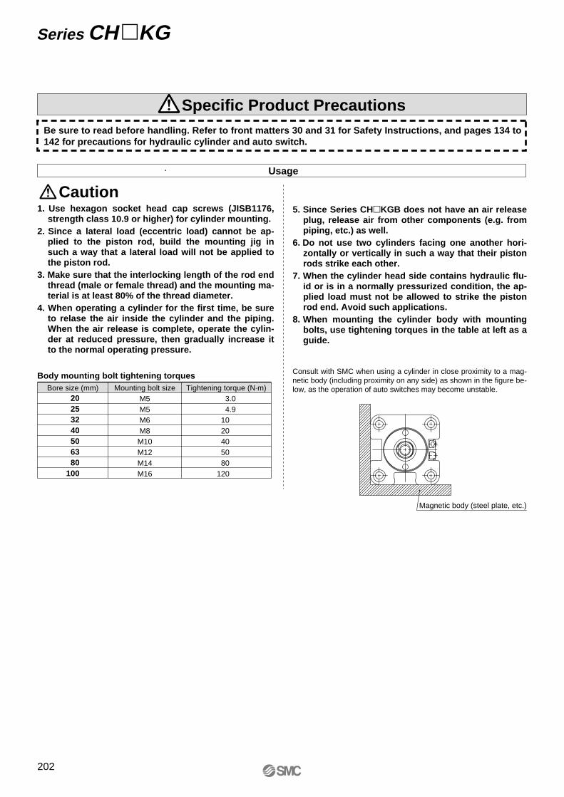
1. Use hexagon socket head cap screws (JISB1176, strength class 10.9 or higher) for cylinder mounting.
2. Since a lateral load (eccentric load) cannot be ap-plied to the piston rod, build the mounting jig in such a way that a lateral load will not be applied to the piston rod.
3. Make sure that the interlocking length of the rod end thread (male or female thread) and the mounting ma-terial is at least 80% of the thread diameter.
4. When operating a cylinder for the first time, be sure to relase the air inside the cylinder and the piping. When the air release is complete, operate the cylin-der at reduced pressure, then gradually increase it to the normal operating pressure.
5. Since Series CH�KGB does not have an air release plug, release air from other components (e.g. from piping, etc.) as well.
6. Do not use two cylinders facing one another hori-zontally or vertically in such a way that their piston rods strike each other.
7. When the cylinder head side contains hydraulic flu-id or is in a normally pressurized condition, the ap-plied load must not be allowed to strike the piston rod end. Avoid such applications.
8. When mounting the cylinder body with mounting bolts, use tightening torques in the table at left as a guide.
Usage
Caution
Body mounting bolt tightening torquesBore size (mm) Mounting bolt size
M5M5M6M8M10M12M14M16
Tightening torque (N·m) 3.0 4.9 10 20 40 50 80 120
20253240506380
100
Magnetic body (steel plate, etc.)
Be sure to read before handling. Refer to front matters 30 and 31 for Safety Instructions, and pages 134 to 142 for precautions for hydraulic cylinder and auto switch.
Consult with SMC when using a cylinder in close proximity to a mag-netic body (including proximity on any side) as shown in the figure be-low, as the operation of auto switches may become unstable.
Series CH �KG
202
Specific Product Precautions

Construction
Parts List Replacement Parts/Seal kitNo.
1
2
3
4
5
6
7
8
9
10
11
12
13
14
15
Bore size (mm)
20
25
32
40
50
63
80
100
Seal kit no.
CHKG20-PS
CHKG25-PS
CHKG32-PS
CHKG40-PS
CHKG50-PS
CHKG63-PS
CHKG80-PS
CHKG100-PS
ContentDescription
Rod cover
Head cover
Cylinder tube
Piston rod
Piston
Bushing
Back-up ring
Magnet
Magnet plate
Switch mounting bracket
Scraper
Rod seal
Piston seal
Tube gasket
Piston gasket
Material
Aluminum alloy
Aluminum alloy
Aluminum alloy
Stainless steel
Copper alloy
Resin
—
Stainless steel
Aluminum alloy
NBR
Note
Black anodized
Black anodized
Hard anodized
With auto switch only
With auto switch only
With auto switch only
With back-up ring
Nos. u, !1, !2, !3 and!4 from the chart at left
r!0 !1 qy !3!5oi !4!2 u te
e
w
ø32 to ø100
Without auto switch
ø20 to ø25
Stainless steel
Carbon steel
ø20, ø25
ø32 to ø100
∗ Seal kit consists of items u, !1, !2, !3 and !4 and can be ordered by using the seal kit number for each bore size.
∗ Special tools are necessary for disassembly. Contact SMC for recommended tool designs and dimensions. Furthermore, ø80 and ø100 are tightened with a large tightening torque, so disassembly will be difficult. Contact SMC if dis-assembly is required.
Hard chromiumelectroplated
Compact Hydraulic Cylinder: 16 MPa Series CH�KG
203
CHQ
CHK�
CHN
CHM
CHS�
CH2�
CHA
D-�
RelatedEquipment

Dimensions
F with effective thread depth G
E
�J
�M
øD
H
C B + Stroke h + Stroke
A + StrokeR
R
c
a
bg
e
Q S
2 x Rc P
Width across flats f
Rod endmale thread
20
25
32
40
50
63
80
100
Bore size (mm)
20
25
32
40
50
63
80
100
Bore size (mm)
A
51
53
66
75
81
90
105
132
B
43
45
56
65
70
77
88
106
C
8
8
10
10
11
13
17
26
D
12
14
18
22.4
28
35.5
45
56
E
10
12
14
19
24
30
41
50
F
M8 x 1.25
M10 x 1.5
M12 x 1.75
M16 x 2
M20 x 2.5
M27 x 3
M30 x 3.5
M39 x 4
G
10
12
15
20
24
33
36
45
H
6
6
7
7
8
9
14
21
J
30
36
47
52
58
69
86
106
K
5.5
5.5
6.6
9
11
13
15
17
L
9.5 depth 5.4
9.5 depth 5.4
11 depth 6.5
14 depth 8.6
17.5 depth 10.8
20 depth 13
23 depth 15.2
26 depth 17.5
a
12.5
15.5
22
27
32
42
57
72
b
15
18
25
30
35
45
60
75
c
M10 x 1.25
M12 x 1.25
M16 x 1.5
M20 x 1.5
M24 x 1.5
M30 x 1.5
M39 x 1.5
M48 x 1.5
e
6
6
7
7
8
9
14
21
f
10
12
14
19
24
30
41
50
h
66
71
91
105
116
135
165
207
g
23
26
35
40
46
58
77
101
M
43
49
63
71
81
100
121
146
P
1/8
1/8
1/4
1/4
1/4
1/4
3/8
3/8
Q
16.5
17
19.5
21.5
24
27.5
31
36
R
6
8
10
10
10
10
15
15
Note 1) Body dimensions are the same with or without auto switches.
(mm)
(mm)
S
11.5
12
19.5
21.5
24
27.5
31
36
Rod end male threads
Basic style/CH�KGB
4 x øK through8 x øL counter bore
Series CH �KG
204

Dimensions
Bore size(mm)
20253240506380
100
LA B BB LC F LCD D E G H K LH LT LX
(mm)
76
78
91
108
121
140
161
189
43
45
56
65
70
77
88
106
70
76
94
108
126
146
172
208
18
18
19
23
27
33
38
43
M8 x 1.25
M10 x 1.5
M12 x 1.75
M16 x 2
M20 x 2.5
M27 x 3
M30 x 3.5
M39 x 4
9.5 depth 5.4
9.5 depth 5.4
11 depth 6.5
14 depth 8.6
17.5 depth 10.8
20 depth 13
23 depth 15.2
26 depth 17.5
6.6
6.6
9
11
14
16
18
22
12
14
18
22.4
28
35.5
45
56
10
12
14
19
24
30
41
50
10
12
15
20
24
33
36
45
6
6
7
7
8
9
14
21
5.5
5.5
6.6
9
11
13
15
17
23
26
33
37
43
52
63
76
15
15
16
20
24
30
35
40
58
64
79
90
104
121
144
174
LW
44.5
50.5
64.5
72.5
83.5
102
123.5
149
Bore size(mm)
20253240506380
100
M P Q R X1 Y1 Z ZZ
43
49
63
71
81
100
121
146
1/8
1/8
1/4
1/4
1/4
1/4
3/8
3/8
16.5
17
19.5
21.5
24
27.5
31
36
6
8
10
10
10
10
15
15
S
11.5
12
19.5
21.5
24
27.5
31
36
15
15
16
20
24
30
35
40
SS
10.5
10.5
11
13
15
18
20.5
23
7.5
7.5
8
10
12
15
17.5
20
58
60
72
85
94
107
123
146
73
75
88
105
118
137
158
186
(mm)
(mm)
a
12.5
15.5
22
27
32
42
57
72
b
15
18
25
30
35
45
60
75
e
6
6
7
7
8
9
14
21
f
10
12
14
19
24
30
41
50
Lg
33
36
44
53
62
78
98
118
Lh
91
96
116
138
156
185
221
264
c
M10 x 1.25
M12 x 1.25
M16 x 1.5
M20 x 1.5
M24 x 1.5
M30 x 1.5
M39 x 1.5
M48 x 1.5
Bore size(mm)
20253240506380
100
Rod end male threadsNote 1) Body dimensions are the same with or without auto switches.
RR
ZZ + Stroke
SQ
LC
H
øD
LA + Stroke
Z + Stroke Y1SS
B + Stroke X1X1
�M
LW
LH
LT
BBLXE
4 x øCD
F with effective thread depth G
Lgeb
a
Rod endmale thread
cWidth across flats f
Lh + Stroke
2 x Rc P
2 x øK through4 x øL counter bore
Foot style/CH�KGL
Compact Hydraulic Cylinder: 16 MPa Series CH �KG
205
CHQ
CHK�
CHN
CHM
CHS�
CH2�
CHA
D-�
RelatedEquipment

Auto Switches: Proper Mounting Positions and Mounting Heights for Stroke End Detection
D-M9�D-M9�WD-M9�ALD-A9�
D-M9�D-M9�WD-M9�ALD-A9�
D-Y5�D-Y7�D-Y7�WD-Y7BALD-Z7�D-Z80
D-M9�VD-M9�WVD-M9�AVLD-Y6�D-Y7�VD-Y7�WVD-A9�V
D-M9�VD-M9�WVD-M9�AVLD-A9�V
ø20, ø25 ø32 to ø100
Auto Switch SpecificationsSeries CH �KG
Refer to pages 347 to 406 for detailed specifications.
20253240506380
100
D-M9�/M9�V D-M9�W/M9�WVD-M9�AL/M9�AVL
D-Y59�/Y69�D-Y7�/Y7�VD-Y7�W/Y7�WVD-Y7BAL
D-A9�/A9�V D-Z7�/Z80
A16 17 18.524 24 26.529.539.5
B15 16 23 26.531.536 44 51.5
A——
13.519 19 21.524.534.5
B——
18 21.526.531 39 46.5
A1213——————
B1112——————
A——
13.519 19 21.524.534.5
B——
18 21.526.531 39 46.5
Auto Switch Proper Mounting Positions
Bore size(mm)
(mm)Solid state auto switch Reed auto switch
20253240506380
100
D-M9�D-M9�WD-M9�ALD-A9�
D-M9�VD-M9�WVD-M9�AVL
D-A9�V
D-Y59�D-Y7PD-Y7�WD-Y7BALD-Z7�D-Z80
D-Y69�D-Y7PVD-Y7�WV
U22 24.531.535.540.550 60.573
U28 30 34.539 45 53.564 76.5
U25.527.5——————
U——
31.535.540.550 60.573
U——
31.536 42 50.561 73.5
Auto Switch Mounting Heights
Bore size(mm)
(mm)
A
B
A
B
A
B
A
B= MA= MA
Note 1) D-A9�/A9�V models cannot be mounted on ø32 to ø100.Note 2) Adjust the auto switch after confirming the operating conditions in the actual setting.
∗ D-A9�/A9�V models cannot be mounted on ø32 to ø100.
206
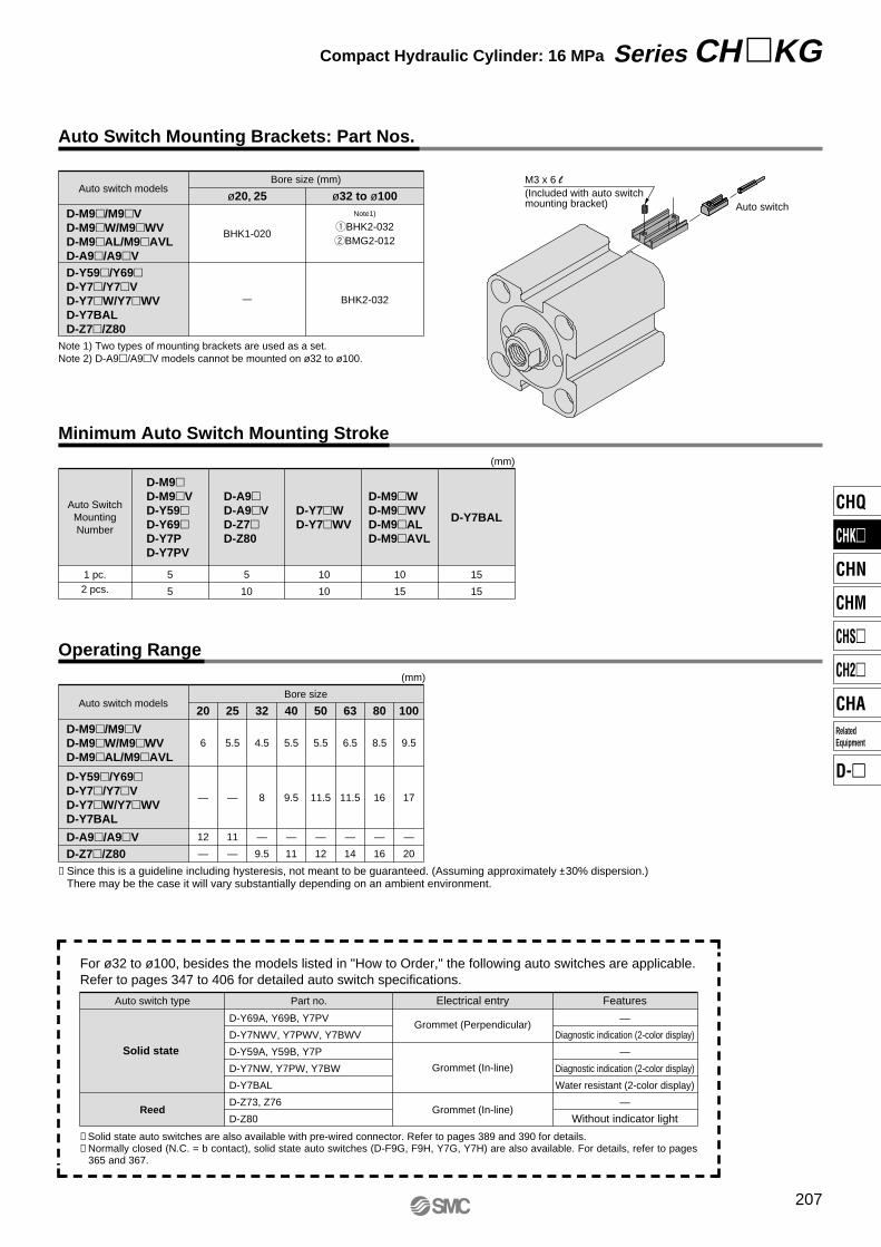
Auto Switch Mounting Brackets: Part Nos.
Minimum Auto Switch Mounting Stroke
∗ Solid state auto switches are also available with pre-wired connector. Refer to pages 389 and 390 for details.∗ Normally closed (N.C. = b contact), solid state auto switches (D-F9G, F9H, Y7G, Y7H) are also available. For details, refer to pages
365 and 367.
For ø32 to ø100, besides the models listed in "How to Order," the following auto switches are applicable.Refer to pages 347 to 406 for detailed auto switch specifications.
Auto switch type Part no. FeaturesElectrical entry
D-Y69A, Y69B, Y7PV
D-Y7NWV, Y7PWV, Y7BWV
D-Y59A, Y59B, Y7P
D-Y7NW, Y7PW, Y7BW
D-Y7BAL
D-Z73, Z76
D-Z80
—
Diagnostic indication (2-color display)
—
Diagnostic indication (2-color display)
Water resistant (2-color display)
—
Without indicator light
Grommet (Perpendicular)
Grommet (In-line)
Grommet (In-line)
Solid state
Reed
Operating Range
Auto switch modelsBore size
20
12
—
25
11
—
32
—
9.5
40
—
11
50
—
12
63
—
14
80
—
16
100
—
20
6 5.5 4.5 5.5 5.5 6.5 8.5 9.5
— — 8 9.5 11.5 11.5 16 17
D-A9�/A9�VD-Z7�/Z80
(mm)
1 pc.2 pcs.
D-M9�D-M9�VD-Y59�D-Y69�D-Y7PD-Y7PV
D-A9�D-A9�VD-Z7�D-Z80
D-Y7�WD-Y7�WV
D-M9�WD-M9�WVD-M9�ALD-M9�AVL
D-Y7BAL
5
5
5
10
10
10
10
15
15
15
Auto SwitchMountingNumber
(mm)
Auto switch modelsBore size (mm)
ø32 to ø100Note1)
qBHK2-032wBMG2-012
ø20, 25
BHK1-020
BHK2-032
D-M9�/M9�VD-M9�W/M9�WVD-M9�AL/M9�AVLD-A9�/A9�VD-Y59�/Y69�D-Y7�/Y7�VD-Y7�W/Y7�WVD-Y7BALD-Z7�/Z80
Note 1) Two types of mounting brackets are used as a set.Note 2) D-A9�/A9�V models cannot be mounted on ø32 to ø100.
M3 x 6 l(Included with auto switch mounting bracket) Auto switch
D-M9�/M9�VD-M9�W/M9�WVD-M9�AL/M9�AVL
D-Y59�/Y69�D-Y7�/Y7�VD-Y7�W/Y7�WVD-Y7BAL
∗ Since this is a guideline including hysteresis, not meant to be guaranteed. (Assuming approximately ±30% dispersion.) There may be the case it will vary substantially depending on an ambient environment.
207
Compact Hydraulic Cylinder: 16 MPa Series CH �KG
CHQ
CHK�
CHN
CHM
CHS�
CH2�
CHA
D-�
RelatedEquipment
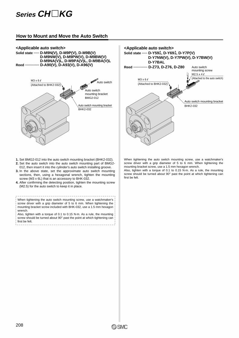
How to Mount and Move the Auto Switch
<Applicable auto switch>Solid state ······ D-M9N(V), D-M9P(V), D-M9B(V)
D-M9NW(V), D-M9PW(V), D-M9BW(V)D-M9NA(V)L, D-M9PA(V)L, D-M9BA(V)L
Reed ··············· D-A90(V), D-A93(V), D-A96(V)
M3 x 6 l
(Attached to BHK2-032)Auto switch
Auto switch mounting bracketBHK2-032
Auto switchmounting bracketBMG2-012
<Applicable auto switch>Solid state ······ D-Y59 , D-Y69 , D-Y7P(V)
D-Y7NW(V), D-Y7PW(V), D-Y7BW(V)D-Y7BAL
Reed ··············· D-Z73, D-Z76, D-Z80 Auto switchmounting screwM2.5 x 4 l(Attached to the auto switch)M3 x 6 l
(Attached to BHK2-032)
Auto switch mounting bracket
BHK2-032
When tightening the auto switch mounting screw, use a watchmaker's screw driver with a grip diameter of 5 to 6 mm. When tightening the mounting bracket screw, use a 1.5 mm hexagon wrench.Also, tighten with a torque of 0.1 to 0.15 N·m. As a rule, the mounting screw should be turned about 90° past the point at which tightening can first be felt.
1. Set BMG2-012 into the auto switch mounting bracket (BHK2-032).2. Set the auto switch into the auto switch mounting part of BMG2-
012, then insert it into the cylinder's auto switch installing groove.3. In the above state, set the approximate auto switch mounting
sections, then, using a hexagonal wrench, tighten the mounting screw (M3 x 6L) that is an accessory to BHK-032.
4. After confirming the detecting position, tighten the mounting screw (M2.5) for the auto switch to keep it in place.
When tightening the auto switch mounting screw, use a watchmaker's screw driver with a grip diameter of 5 to 6 mm. When tightening the mounting bracket screw included with BHK-032, use a 1.5 mm hexagon wrench.Also, tighten with a torque of 0.1 to 0.15 N·m. As a rule, the mounting screw should be turned about 90° past the point at which tightening can first be felt.
AB
AB
Series CH �KG
208
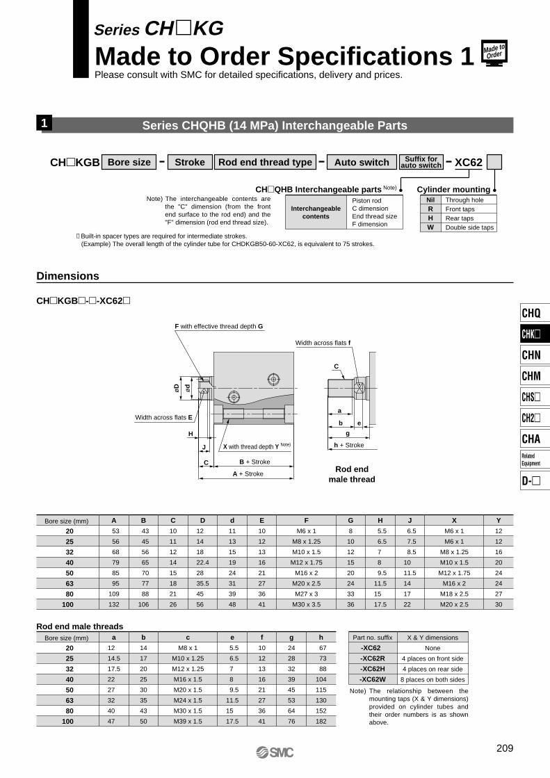
Series CHQHB (14 MPa) Interchangeable Parts
CH�KGB XC62
Piston rodC dimensionEnd thread sizeF dimension
Interchangeablecontents
CH�QHB Interchangeable parts Note)
Through holeFront tapsRear tapsDouble side taps
NilRHW
Cylinder mounting
Dimensions
F with effective thread depth G
CH�KGB�-�-XC62�
X with thread depth Y Note)
B + Stroke
h + Stroke
A + Stroke
Width across flats E
Width across flats f
H
øD ød
J
C
C
a
b
g
e
Rod endmale thread
1
Bore size (mm)
20
25
32
40
50
63
80
100
A
53
56
68
79
85
95
109
132
B
43
45
56
65
70
77
88
106
C
10
11
12
14
15
18
21
26
d
11
13
15
19
24
31
39
48
D
12
14
18
22.4
28
35.5
45
56
E
10
12
13
16
21
27
36
41
G
8
10
12
15
20
24
33
36
H
5.5
6.5
7
8
9.5
11.5
15
17.5
J
6.5
7.5
8.5
10
11.5
14
17
22
Y
12
12
16
20
24
24
27
30
F
M6 x 1
M8 x 1.25
M10 x 1.5
M12 x 1.75
M16 x 2
M20 x 2.5
M27 x 3
M30 x 3.5
X
M6 x 1
M6 x 1
M8 x 1.25
M10 x 1.5
M12 x 1.75
M16 x 2
M18 x 2.5
M20 x 2.5
Bore size (mm)
20
25
32
40
50
63
80
100
a
12
14.5
17.5
22
27
32
40
47
b
14
17
20
25
30
35
43
50
c
M8 x 1
M10 x 1.25
M12 x 1.25
M16 x 1.5
M20 x 1.5
M24 x 1.5
M30 x 1.5
M39 x 1.5
e
5.5
6.5
7
8
9.5
11.5
15
17.5
f
10
12
13
16
21
27
36
41
g
24
28
32
39
45
53
64
76
h
67
73
88
104
115
130
152
182
Part no. suffix
-XC62
-XC62R
-XC62H
-XC62W
X & Y dimensions
None
4 places on front side
4 places on rear side
8 places on both sides
Note) The relationship between the mounting taps (X & Y dimensions) provided on cylinder tubes and their order numbers is as shown above.
Rod end male threads
∗ Built-in spacer types are required for intermediate strokes.(Example) The overall length of the cylinder tube for CHDKGB50-60-XC62, is equivalent to 75 strokes.
Bore size Rod end thread type Auto switch Suffix forauto switchStroke
Note) The interchangeable contents are the "C" dimension (from the front end surface to the rod end) and the "F" dimension (rod end thread size).
Series CH�KGMade to Order Specifications 1Please consult with SMC for detailed specifications, delivery and prices.
Made toOrder
209
CHQ
CHK�
CHN
CHM
CHS�
CH2�
CHA
D-�
RelatedEquipment

Intermediate strokes in 5 mm increments can be manufactured by installing spacers inside standard stroke cylinders.
CH�KGB XC63
CH�KGL XC63
CH�KGB�-�-XC63
B
A
Intermediate Stroke Type (Built-in spacer type)2
Dimensions
Applicable cylinder tubeFor 75 mm stroke
For 100 mm strokeFor 125 mm strokeFor 150 mm strokeFor 75 mm stroke
For 100 mm strokeFor 125 mm strokeFor 150 mm strokeFor 175 mm stroke
Applicable stroke55, 60, 65, 7080, 85, 90, 95
105, 110, 115, 120130, 135, 140, 145
55, 60, 65, 7080, 85, 90, 95
105, 110, 115, 120130, 135, 140, 145155, 160, 165, 170
Bore size (mm)
Intermediate stroke
32
40506380100
32
40
50
63
80
100
A
141
150
156
165
180
207
A
166
175
181
190
205
232
B
131
140
145
152
163
181
B
156
165
170
177
188
206
StrokeBore size(mm)
55, 60, 65, 70 80, 85, 90, 95
A
191
200
206
215
230
257
B
181
190
195
202
213
231
105, 110, 115, 120
A
216
225
231
240
255
282
B
206
215
220
227
238
256
130, 135, 140, 145
A
—
250
256
265
280
307
B
—
240
245
252
263
281
155, 160, 165, 170
Note) Dimensions other than those highlighted above are standard.
Dimensions
CH�KGL�-�-XC63
32
40
50
63
80
100
LA
166
183
196
215
236
264
LA
191
208
221
240
261
289
B
131
140
145
152
163
181
Z
147
160
169
182
198
221
B
156
165
170
177
188
206
Z
172
185
194
207
223
246
55, 60, 65, 70 80, 85, 90, 95
LA
216
233
246
265
286
314
B
181
190
195
202
213
231
Z
197
210
219
232
248
271
105, 110, 115, 120
LA
241
258
271
290
311
339
B
206
215
220
227
238
256
Z
222
235
244
257
273
296
130, 135, 140, 145
LA
—
283
296
315
336
364
B
—
240
245
252
263
281
Z
—
260
269
282
298
321
155, 160, 165, 170
LA
BZ
StrokeBore size(mm)
Bore size Rod end thread type Auto switch Suffix forauto switchStroke
Bore size Rod end thread type Auto switch Suffix forauto switchStroke
Series CH�KGMade to Order Specifications 2Please consult with SMC for detailed specifications, delivery and prices.
Made toOrder
210

Air release valves are provided on cylinder tube surfaces machined for ports.
CH�KGB XC64
With air release valve
CH�KGL XC64
CH�KGB�-�-XC64Bore size (mm)
20
25
32
40
50
63
80
100
A
16.5
17
19.5
21.5
24
27.5
31
36
C
7
8
10
10
10
10
15
15
B
9.5
10
17
18.5
21.5
24
27.5
33
Note) Dimensions other than those highlighted above are standard.
A
B
C
CWith Air Release Valve3
Dimensions
CH�KGL�-�-XC64
A
C
C
B
Bore size Rod end thread type Auto switch Suffix forauto switchStroke
Bore size Rod end thread type Auto switch Suffix forauto switchStroke
Series CH�KGMade to Order Specifications 3Please consult with SMC for detailed specifications, delivery and prices.
Made toOrder
211
CHQ
CHK�
CHN
CHM
CHS�
CH2�
CHA
D-�
RelatedEquipment