Embed Size (px)
Citation preview
ICAS 2002 CONGRESS
842.1
Abstract
Several years ago, GE Aircraft Engines realizedthat with the expected increased stringency ofStage 4 noise regulations, the continued thrustgrowth of engine famili es, and increasingenvironmental pressures, jet noise wouldbecome a restricting factor in aircraftoperations. An internal research anddevelopment program, with some invaluableassistance from NASA, was started toinvestigate how to reduce jet noise whileachieving acceptable impacts on performance,operabilit y, manufacturabilit y, weight, etc.…The chevron nozzle for separate flow exhaustsystems was the outcome, reducing jet noise byenhancing mixing of the fan, core and ambientstreams faster than conventional nozzles, with aminimal impact on performance. The chevronnozzle, consisting of cut-outs around theperimeter of the nozzle, generates stream-wisevorticity, enhancing the mixing between the twostreams, reducing the peak velocity morequickly and therefore reducing peak noise. Thephysical blockage is very small with thisconcept, with relatively small i mpact on thrustand flow, attributed to the aerodynamicblockage of the streamwise vortices. Thistechnology was developed in 1996, became partof a production exhaust system in 1999, and wasfirst flown on an airplane in 2001. This paperprovides a brief overview of this technology.
1 Introduction
In January of 2001 the proposal for a newaircraft noise certification standard (ICAOAnnex 16, Vol. 1, Chapter 4) was announced,requiring 10 dB margin to Annex 16, Chapter 3,
with the sum of any two certification pointstotaling at least 2 dB, and no trades betweenpoints. This new standard was anticipated, andsome current engine aircraft combinations wereknown to require changes to remain incompliance. Trades were allowed in the pastwhere at one certification point the noise couldbe above the certification limit . In cases wherean aircraft had low noise at two certificationpoints but exceeded the allowable limit at a highpower setting associated with take-off , forexample, it could still be compliant withcertification rules, as long as the noise level didnot exceed the rule by more than 2 dB. Also,over the years engine families have grown, inmany cases with increased throttle settings tocompensate for heavier or extended rangeaircraft, which raises the exit velocity of the jet.As a rule of thumb, jet noise correlates with V8
[1]; thus any increase in jet velocity correspondsto a very fast increase in noise.
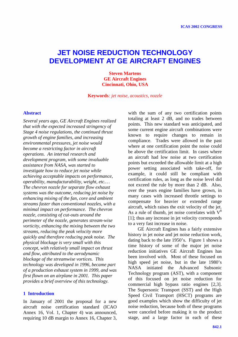
GE Aircraft Engines has a fairly extensivehistory in jet noise and jet noise reduction work,dating back to the late 1950’s. Figure 1 shows atime history of some of the major jet noisereduction initiatives GE Aircraft Engines hasbeen involved with. Most of these focused onhigh speed jet noise, but in the late 1980’sNASA initiated the Advanced SubsonicTechnology program (AST), with a componentof this focused on jet noise reduction forcommercial high bypass ratio engines [2,3].The Supersonic Transport (SST) and the HighSpeed Civil Transport (HSCT) programs aregood examples which show the diff iculty of jetnoise reduction, because both of these programswere canceled before making it to the productstage, and a large factor in each of these
JET NOISE REDUCTION TECHNOLOGYDEVELOPMENT AT GE AIRCRAFT ENGINES
Steven MartensGE Aircraft Engines
Cincinnati, Ohio, USA
Keywords: jet noise, acoustics, nozzle
STEVEN MARTENS
842.2
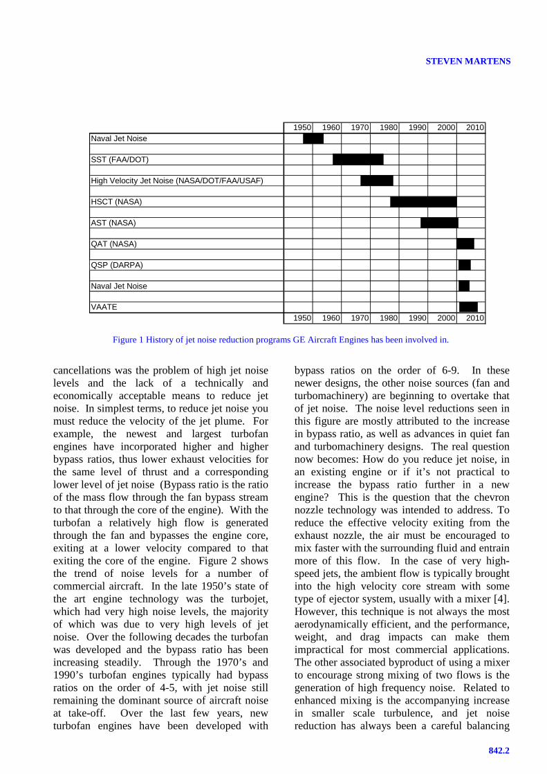
cancellations was the problem of high jet noiselevels and the lack of a technically andeconomically acceptable means to reduce jetnoise. In simplest terms, to reduce jet noise youmust reduce the velocity of the jet plume. Forexample, the newest and largest turbofanengines have incorporated higher and higherbypass ratios, thus lower exhaust velocities forthe same level of thrust and a correspondinglower level of jet noise (Bypass ratio is the ratioof the mass flow through the fan bypass streamto that through the core of the engine). With theturbofan a relatively high flow is generatedthrough the fan and bypasses the engine core,exiting at a lower velocity compared to thatexiting the core of the engine. Figure 2 showsthe trend of noise levels for a number ofcommercial aircraft. In the late 1950’s state ofthe art engine technology was the turbojet,which had very high noise levels, the majorityof which was due to very high levels of jetnoise. Over the following decades the turbofanwas developed and the bypass ratio has beenincreasing steadily. Through the 1970’s and1990’s turbofan engines typically had bypassratios on the order of 4-5, with jet noise stillremaining the dominant source of aircraft noiseat take-off. Over the last few years, newturbofan engines have been developed with
bypass ratios on the order of 6-9. In thesenewer designs, the other noise sources (fan andturbomachinery) are beginning to overtake thatof jet noise. The noise level reductions seen inthis figure are mostly attributed to the increasein bypass ratio, as well as advances in quiet fanand turbomachinery designs. The real questionnow becomes: How do you reduce jet noise, inan existing engine or if it’s not practical toincrease the bypass ratio further in a newengine? This is the question that the chevronnozzle technology was intended to address. Toreduce the effective velocity exiting from theexhaust nozzle, the air must be encouraged tomix faster with the surrounding fluid and entrainmore of this flow. In the case of very high-speed jets, the ambient flow is typically broughtinto the high velocity core stream with sometype of ejector system, usually with a mixer [4].However, this technique is not always the mostaerodynamically eff icient, and the performance,weight, and drag impacts can make themimpractical for most commercial applications.The other associated byproduct of using a mixerto encourage strong mixing of two flows is thegeneration of high frequency noise. Related toenhanced mixing is the accompanying increasein smaller scale turbulence, and jet noisereduction has always been a careful balancing
1950 1960 1970 1980 1990 2000 2010Naval Jet Noise
SST (FAA/DOT)
High Velocity Jet Noise (NASA/DOT/FAA/USAF)
HSCT (NASA)
AST (NASA)
QAT (NASA)
QSP (DARPA)
Naval Jet Noise
VAATE1950 1960 1970 1980 1990 2000 2010
Figure 1 History of jet noise reduction programs GE Aircraft Engines has been involved in.
842.3
JET NOISE REDUCTION TECHNOLOGY DEVELOPMENT ATGENERAL ELECTRIC AIRCRAFT ENGINES
act between low frequency noise reduction(decreased mean velocity) and high frequencynoise generation (increased turbulence/smallscale mixing). For supersonic applications, arelatively long duct is used downstream of themixer, sometimes lined with acoustic treatmentto attenuate the excess high frequency noisegenerated by the mixing. This is also the typeof configuration used for many older Stage 2engines, which have incorporated ‘hush-kits’ .Also, long-duct, mixed-flow engines, which mixthe core and fan streams with a lobed mixer,may incorporate this jet noise reduction design.However, this type of exhaust system has arelatively longer length, higher weight, andincreased scrubbing drag. Alternatively, aproperly designed chevron creates streamwisevorticity which enhances the mixing betweenthe fan and core streams with littl e to noincrease in high frequency noise.
2 The Chevron Nozzle
2.1 Chevron Nozzle Development Program
A program was started in early 1999 to developa noise reduction upgrade package for the
CFM56-5B engine. This engine was developedjointly by GE Aircraft Engines and SnecmaMoteurs, to power the A321 narrow bodyaircraft, and has been in passenger service formany years. The upgrade package wasenvisioned to ensure that this aircraft wouldmeet the new Chapter 4 noise certificationrequirements and allow this widely utili zedaircraft to continue to operate without noiserestrictions.
The chevron nozzle is a major element ofthis upgrade package, forecast to provide asignificant amount of noise reduction. Thespecific goal was to maximize the noisereduction with the chevron while minimizingany negative impacts on the rest of theengine/aircraft system. This has been a verysuccessful program and the remainder of thepaper summarizes the test results obtained at theGE Aircraft Engines acoustic test facili ty, Cell41.
The overall chevron development programcontained many elements that resulted in anexcellent noise reduction design. The approachstarted with computational fluid dynamicstudies (CFD) of different chevron designs, anumber of which were built and tested on a1/11th linear scale model of the exhaust system.These tests were used to determine the jet noisereduction compared to the current production
120
110
100
901950 1960 1970 1980 1990 2000
707-100
DC-9-10737-200
727-200
747-200
DC-10-30
A310
737-300
737-200 A321
747-400 A330
Noiselevel,
EPNdB(1500’
sideline)
Turbojet
First GenerationTurbofan
Second GenerationTurbofan
• Normalized to 100,000-lb. thrust• Noise levels are for airplane/engine
configurations at time of initial service
IncreasingBypassRatio
High BypassTurbofan ~5+
Figure 2 History of commercial aircraft noise levels and progression of engine type and bypass ratio.

STEVEN MARTENS
842.4
exhaust system both for static conditions as wellas for simulated forward flight. This test wasused to downselect to a smaller number ofviable acoustic designs and then tested forperformance (flow and thrust coeff icient). Afteranother round of down-selecting, taking intoaccount the noise reduction and effect on flowand thrust, the scale model was tested at theCEPRA 19 acoustic facili ty at ONERA with a1/11th scale model of the A321 wing. This testensured that there were no major installation orintegration effects on the acoustic performanceof the chevron nozzle.
2.2 Facility
The acoustic results discussed in this paper wereobtained at GE Aircraft Engines test faciliti es.The GE Aircraft Engines Cell 41 anechoic free-jet noise facili ty, shown in Figure 3, is acylindrical chamber 43 feet in diameter and 72feet tall . The inner surfaces of the chamber arelined with anechoic wedges made of f iberglasswool to render the facilit y anechoic above 220Hz. The facili ty can accommodate single anddual flow model configurations, the dual flowrepresenting the core and fan stream of a typicalhigh-bypass ratio, separate flow exhaust system.The two streams of heated air for the dual flowarrangement, produced by two separate naturalgas burners, flow through silencers and plenumchambers before entering the test nozzle. Eachstream can be heated to a maximum temperatureof 1960 oR with nozzle pressure ratios as high as5.5, resulting in a maximum jet velocity of3,000 ft/sec, with throat areas of 22 in2 and 24in2 for the core and fan streams, respectively.For the tests discussed in this paper, the nozzletemperature, nozzle pressure ratio, and massflow requirements are well within thecapabiliti es of the facili ty.
The tertiary air system (for flightsimulation) consists of a 250,000 scfm (at 50”of water column static pressure) fan driven by a3,500 horsepower electric motor. The transitionductwork and silencer route air from the fandischarge through a 48” diameter free-jetnozzle. The silencer reduces the fan noise by 30to 50 dB. Tertiary airflow at its maximum
delivery rate permits flight simulation up to afree jet Mach number of approximately 0.4.Mach number variation is achieved by adjustingthe supply air fan inlet vanes. The combinedmodel, free-jet, and entrained airflow isexhausted through an exhaust ‘T’ stack silenceraligned directly over the model in the ceili ng ofthe chamber. The exhaust ‘T’ stack isacoustically treated to reduce noise transferfrom the facili ty to the surrounding community.
The facili ty is equipped with a traversingtower containing 13 microphones, mounted atpolar angles from 45o to 155o, seen in Figure 3,and provides measurements at a minimumdistance of 22 feet from the nozzle referencelocation, (see Figure 4) to measure the acousticcharacteristics of the test models in the far-field.Figure 4 also shows a layout of the facili ty,indicating the orientation of the model hardwareand the microphone locations. The tower can bephysically positioned at any azimuthal anglenoted in Figure 4. However, to ensure non-interference from close proximity to wedges inits extreme positions, data acquisition isnormally limited to the 0o to 90o locationsidentified on Figure 4. An azimuthal angle of
LaserVelocimeterTrack
Exhaust Silencer
TraversingMicrophoneArray
EntrainedFlow
Inlet AirSilencer
TertiaryFlow
Free Jet Exit
MicrophoneLocations
155o
150o
140o
130o
120o
110o
100o
90o
80o
70o
60o
50o
45o
Nozzle Exit
22 ft
25 ft
2 Stream ModelNozzle Flow
Figure 3 Side-view schematic of Cell 41.

842.5
JET NOISE REDUCTION TECHNOLOGY DEVELOPMENT ATGENERAL ELECTRIC AIRCRAFT ENGINES
zero is defined as the 45o (N-E) position.Acoustic microphone data is typically acquiredat two azimuthal angles to simulate the sidelineand community noise measurements requiredfor FAR 36 certification. For these experimentsthe sideline noise measurements were made at34 degrees and the community noise or cutbacknoise was measured at 90 degrees,(microphones aligned with the model such thatthe pylon is on the far side of the exhaustsystem model) identified on Figure 4.
2.3 Chevron Description and Design
Chevron nozzles were first tested at GE AircraftEngines in 1996 during an internally fundedprogram, which looked at a variety of differentjet noise reduction concepts. The chevronsproved to be the most promising conceptdeveloped in terms of noise reduction andperformance impact, and were further developedin testing at NASA Glenn Research Centerunder the AST program [2,3]. The idea forchevrons came from a myriad of sources,including work done on tabbed nozzles [5-8],nozzles with cutouts [9-12], mixer nozzles [13-
15], and general knowledge and experiencedeveloped over the years at GE AircraftEngines.
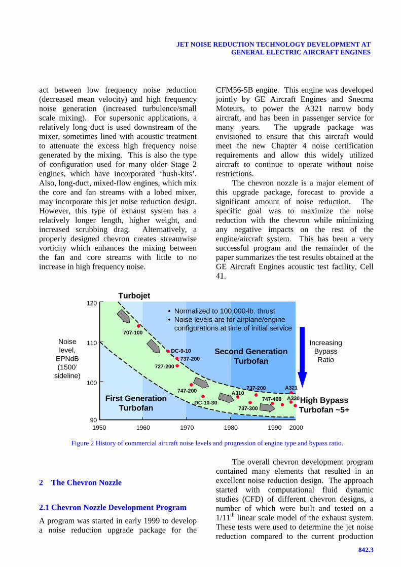
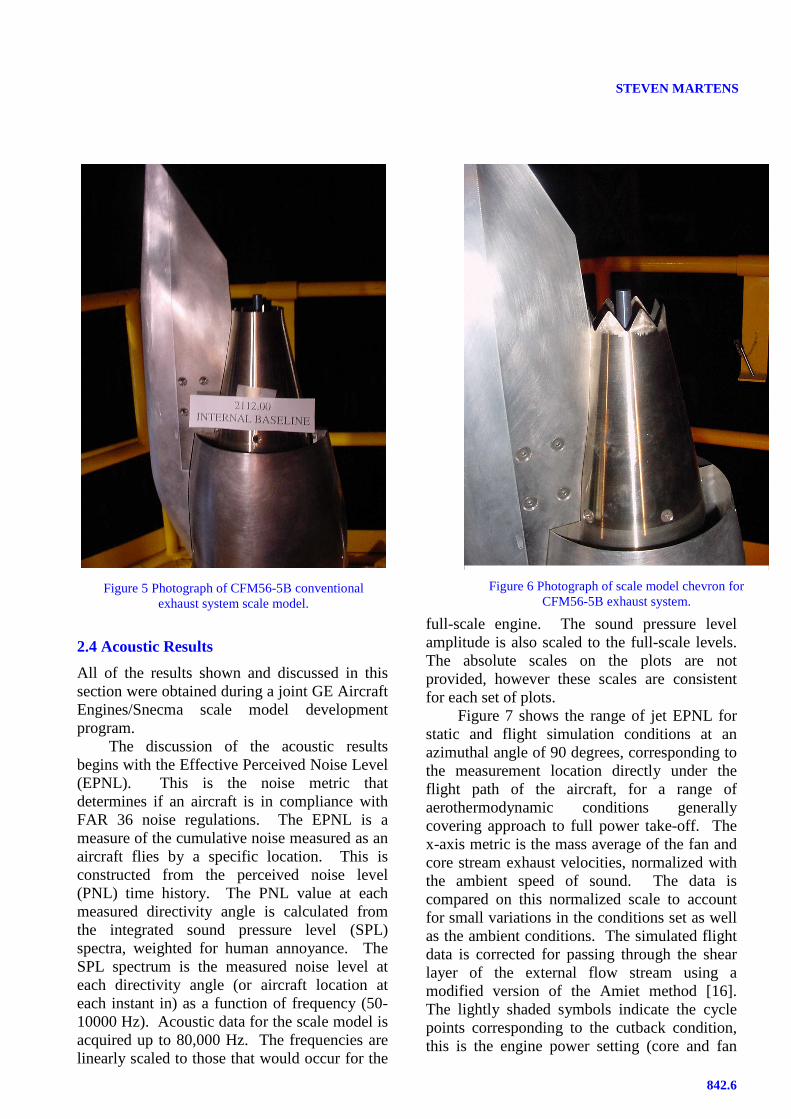
Figure 5 shows a photograph of a 1/11th-scale model of the CFM56-5B exhaust system.This engine model powers the A321 narrow-body aircraft. The chevron nozzle, shown inFigure 6, was chosen after testing a number ofdesign concepts with various permutations ofthe design parameters of the chevron nozzle.Some of these parameters are: number ofchevrons or cut-outs, length, width, aspect ratio,sweep angle, penetration, shape, azimuthalcontouring, relative axial location, etc.… Initialdesign screening was done using computationalfluid dynamics (CFD) analysis to qualitativelycompare the mixing characteristics of the jetplume for different chevron designs relative tothe baseline configuration. The chevron nozzleused for discussion in this paper has 8 chevronsthat alternate penetration into and away from theengine centerline. In general the chevron designselection must consider acoustic benefit,performance, operabili ty, manufacturabili ty,maintainabili ty, etc.… Unfortunately, acousticsand performance usually have an inverserelationship; that is, what’s good for acousticsgenerally is bad for performance. The art is indesigning a nozzle that maximizes acousticbenefit and minimizes negative performanceimpact, while meeting the remaining systemrequirements.
An important and often unrecognizedaspect of the chevron nozzle is their inherentdifference to tabbed nozzles. Tabbed nozzles,like mixers, shift the frequencies of noisegenerated. They move energy from lowfrequencies to high frequencies. Chevrons, onthe other hand, are designed with an aim toreduce low frequencies while leaving the highfrequency acoustic characteristics essentially thesame as a conventional nozzle. There may besome very slight increases in noise at somemoderate to high frequencies, but in eff icientchevron designs, it is usually insignificant whentaking into account other engine sources, whichare typically usually higher than the jet noise atthese frequencies.
S
Min Traverse Location
Tower Mounted MicrophonesTraverse Track
45
Max Traverse Location
22ft R
Reference LineCell 41
NF
F
F
F
F
=-10
=45
=90
=100
=0
F =34
Pylon
Figure 4 Plan view of Cell 41 showingmicrophone locations and measurement
orientations.
STEVEN MARTENS
842.6
2.4 Acoustic Results
All of the results shown and discussed in thissection were obtained during a joint GE AircraftEngines/Snecma scale model developmentprogram.
The discussion of the acoustic resultsbegins with the Effective Perceived Noise Level(EPNL). This is the noise metric thatdetermines if an aircraft is in compliance withFAR 36 noise regulations. The EPNL is ameasure of the cumulative noise measured as anaircraft flies by a specific location. This isconstructed from the perceived noise level(PNL) time history. The PNL value at eachmeasured directivity angle is calculated fromthe integrated sound pressure level (SPL)spectra, weighted for human annoyance. TheSPL spectrum is the measured noise level ateach directivity angle (or aircraft location ateach instant in) as a function of frequency (50-10000 Hz). Acoustic data for the scale model isacquired up to 80,000 Hz. The frequencies arelinearly scaled to those that would occur for the
full-scale engine. The sound pressure levelamplitude is also scaled to the full-scale levels.The absolute scales on the plots are notprovided, however these scales are consistentfor each set of plots.
Figure 7 shows the range of jet EPNL forstatic and flight simulation conditions at anazimuthal angle of 90 degrees, corresponding tothe measurement location directly under theflight path of the aircraft, for a range ofaerothermodynamic conditions generallycovering approach to full power take-off. Thex-axis metric is the mass average of the fan andcore stream exhaust velocities, normalized withthe ambient speed of sound. The data iscompared on this normalized scale to accountfor small variations in the conditions set as wellas the ambient conditions. The simulated flightdata is corrected for passing through the shearlayer of the external flow stream using amodified version of the Amiet method [16].The lightly shaded symbols indicate the cyclepoints corresponding to the cutback condition,this is the engine power setting (core and fan
Figure 5 Photograph of CFM56-5B conventionalexhaust system scale model.
Figure 6 Photograph of scale model chevron forCFM56-5B exhaust system.

842.7
JET NOISE REDUCTION TECHNOLOGY DEVELOPMENT ATGENERAL ELECTRIC AIRCRAFT ENGINES
nozzle pressure ratios and temperatures)corresponding to the cutback or fly-over Annex16 Chapter 3 certification point(Vmix/Aamb=0.86, Vmix=990 ft/sec). Thestatic data shows a constant modest noisereduction at normalized velocities up to about0.8, then a steadily increasing noise benefit dueto the chevron nozzle at higher levels. Thesimulated-flight conditions also exhibit the sametrend with a slightly larger noise reduction at thesame normalized velocity. Acoustic data wasnot acquired for the lowest normalizedvelocities for the simulated flight conditionsbecause it is very hard to distinguish this lowlevel of jet noise from the free-jet backgroundnoise.
Figure 8 shows the same results as Figure 7for the same aero-thermodynamic cycleconditions, at an azimuthal angle of 34 degrees,corresponding to the sideline configuration, thecertification point corresponding to themeasurement location offset to the aircraft flightpath. The shaded symbols correspond to thesideline engine cycle conditions(Vmix/Aamb=1, Vmix=1150 ft/sec). The noiselevel at this orientation follows a very similartrend as the fly-over orientation. Oneinteresting difference between the twoorientations is that the absolute noise level ishigher at the sideline orientation than the fly-over orientation, even for static data. This noisedifference is li kely due to the pylon - the mixingcharacteristics of the jet plume may vary in the
azimuthal direction due to the effects of thepylon - this has been observed in computationalwork on chevron nozzles [17].
Figure 9 shows the jet PNL directivity forthe cutback cycle condition and measurementlocation for the conventional and chevronnozzle for both static and M=0.25 flightconditions (corresponding to the lightly shadedsymbols on Figure 7). The static data shows avery slight benefit for the chevron nozzle overall angles. In this plot the measured data coversdirectivity angles of 45 to 155 degrees (180degrees is directly behind the engine), the otherangles are simple extrapolations of the dataassuming spherical spreading. In the case of theM=0.25 flight simulation data the noisedifference characteristics are different. In themid-range angles (60 – 90 degrees) theconventional and chevron nozzle noise levelsare essentially the same. In the aft angles (≥100 degrees) the chevron provides increasingnoise reduction benefit. However, in theforward angles (≤ 60 degrees) the chevron maybe slightly louder than the conventional nozzle.Figure 10 shows the same information for thesideline cycle condition and measurementorientation (corresponding to the lightly shadedsymbols on Figure 8). For the sideline cyclecondition it is obvious that the chevron nozzleprovides more benefit than the lower velocitycondition at cutback. For the static conditions,the open symbols, the chevron nozzle shows afairly constant level of noise reduction over
Figure 7 Jet effective perceived noise level as afunction of normalized velocity for the cutback
measurement location.
0.5 0.6 0.7 0.8 0.9 1 1.1
Vmix/Aamb
Jet
Eff
ecti
ve P
erci
eved
No
ise
Lev
el (
EP
Nd
B)
Conventional Nozzle
Chevron Nozzle
Open Symbols - Static DataClosed Symbols - M=0.25 Flight Simulation Data
Single Engine Freefield Data
5 EPNdB
0.5 0.6 0.7 0.8 0.9 1 1.1
Vmix/Aamb
Jet
Eff
ecti
ve P
erci
eved
No
ise
Lev
el (
EP
Nd
B)
Conventional Nozzle
Chevron Nozzle
Open Symbols - Static DataClosed Symbols - M=0.25 Flight Simulation Data
Single Engine Freefield Data
5 EPNdB
Figure 8 Jet effective perceived noise level as a functionof normalized velocity for the sideline measurement
location.

STEVEN MARTENS
842.8
most of the directivity angle range. At the mostaft angles (≥ 150 degrees) the conventional andchevron nozzle noise levels are approximatelythe same. For the M=0.25 flight simulationcase, the chevron provides a fairly constantmoderate reduction in PNL up to a directivityangle of approximately 110 degrees. Aft of thisthe chevron provides a reduction ofapproximately 2.5 to 3 PNdB. Thus the chevronis most effective at the most aft angles, wherejet noise really peaks. Another striking featureof Figure 10 is the difference in chevron nozzleeffectiveness between static and simulated flightdata. The chevron nozzle provides more noisereduction with flight simulation than does thestatic case. The reason for this is currentlyunknown.
Figure 11 shows the jet (SPL) spectra forthe cutback cycle condition and measurementlocation for three directivity angles, 90, 130,and 150 degrees for the conventional andchevron nozzle configurations. At the 90-degree location, the chevron provides a coupleof dB reduction up to approximately 800 Hz.Above 800 Hz, the two configurations virtuallylie atop one another. There are somefrequencies where the chevron is slightly higherthan the conventional nozzle. This slight noiselevel increase at the higher frequencies is due tothe increased small-scale turbulence that is abyproduct of the streamwise vorticity generatedby the chevrons. In the design of the chevron
nozzle this is an area that requires carefulmonitoring. The geometric parameters of thechevron nozzle are balanced with the aero-thermodynamic conditions to provide amaximum low frequency noise reduction with aminimum high frequency noise impact.
Some amount of high frequency noise levelincrease can be acceptable in the jet noisespectra because in the engine there are othernoise sources that are dominant in thisfrequency range. This is the effect that resultedin the slight PNL increase for the forwardangles in the simulated flight data at cutbackconditions on Figure 9. This is one of the mainaspects that makes jet noise reduction so
Figure 9 Jet perceived noise level directivity, staticand M=0.25 simulated flight conditions, conventional
and chevron nozzle, cutback cycle condition(Vmix/Aamb=0.86) and measurement location.
0 20 40 60 80 100 120 140 160 180
Directivity Angle (degrees)
Jet
Per
ciev
ed N
ois
e L
evel
(P
Nd
B)
Conventional Nozzle
Chevron Nozzle
Open Symbols - Static DataClosed Symbols - M=0.25 Flight Simulation
Single Engine Freefield Data
5 PNdB
Figure 10 Jet perceived noise level directivity, staticand M=0.25 simulated flight conditions, conventional
and chevron nozzle, sideline cycle condition(Vmix/Aamb=1) and measurement location.
0 20 40 60 80 100 120 140 160 180
Directivity Angle (degrees)
Jet
Per
ciev
ed N
ois
e L
evel
(P
Nd
B)
Conventional Nozzle
Chevron Nozzle
Open Symbols - Static DataClosed Symbols - M=0.25 Flight Simulation
Single Engine Freefield Data
5 PNdB
Figure 11 Jet sound pressure level spectra forM=0.25 simulated flight conditions, conventional and
chevron nozzle, cutback cycle condition(Vmix/Aamb=0.86) and measurement location, 90,
130, and 150 degree directivity angles.
10 100 1000 10000
Frequency (Hz)
Jet
So
un
d P
ress
ure
Lev
el (
dB
)
90 degrees
130 degrees
150 degrees
Single Engine Freefield Data
Solid Line - Conventional NozzleDashed Line - Chevron Nozzle
5 dB

842.9
JET NOISE REDUCTION TECHNOLOGY DEVELOPMENT ATGENERAL ELECTRIC AIRCRAFT ENGINES
diff icult in practice. This seesaw effect caneliminate an overall noise benefit in the EPNLeven when there may be some significant noisereductions at some frequencies and angles. Theother two angles, 130 and 150 degrees, showsimilar low frequency noise benefits up to about500 Hz, and above that generally show the samenoise level as the conventional nozzle.
Figure 12 shows the same information atthe sideline cycle condition and measurementlocation. As seen previously in the PNL andEPNL plots at the higher velocities the chevronresults in larger noise reductions. At the 90-degree directivity angle the benefit continues toapproximately 1000 Hz. At 130 degrees thechevron benefit is larger, on the order of 3 – 4dB, again up to frequencies around 1000 Hz.Finally, at 150 degrees the chevron is providingSPL reductions up to 5 dB at the lowerfrequencies and the benefit extends through thecomplete frequency range, at smaller levels.
Figures 7 and 8 showed jet EPNLreductions on the order of 2 – 3 EPNdB. Torelate this to the engine system noise reductionthe chevron would produce, these jet noisereductions would need to be evaluated using anengine system flyover noise analysis. Theultimate noise reduction is a function of howdominant the jet noise component is relative to
the other engine noise sources at eachappropriate aero-thermodynamic condition.
These results have shown that a properlydesigned chevron for a particular engine cycleand geometry can effectively reduce the jetnoise, over most frequencies and angles, andwhen taken with the other engine noise sources,essentially pay no price for increasing noise atany frequency or angle. This design process hasalso taken into account other considerations tominimize any other effects to the engine oraircraft. Special consideration is paid to thechevron’s effect on the thrust and flowcoeff icient.
3 Conclusions
This paper has discussed some of the long-termhistory of jet noise reduction and specifically asummary of the development of the chevronnozzle for jet noise reduction for high bypassratio separate flow exhaust systems. Jet noisereduction is a very diff icult task due to theconstraints imposed by engine and aircraftsystem requirements. It is extremely diff icult toreduce jet noise while not impacting anythingelse negatively. Chevrons are unique, as a jetnoise reduction technology, in that they canhave a relatively small impact on weight,performance, and operabili ty.
Jet noise is only one component of the totalengine and aircraft system noise signature, butthe jet noise reductions demonstrated herein canadd up to a significant cumulative system noisereduction, depending on the engine and aircraftunder consideration. Continued chevrondevelopment for the CFM56-5B, has includedscale model tests with the exhaust systemmounted under a scale model wing. Staticengine testing is scheduled for June of 2003,and flight-testing should occur the fall of 2003.
The chevron nozzle has proven to be anexcellent technology developed jointly betweenGE Aircraft Engines and NASA as an effectiveand eff icient means to reduce jet noise withminimal impact on engine performance,operabili ty, weight, and cost, for some aircraftsystems. This has been an especially importanttechnology development because in some cases
Figure 12 Jet sound pressure level spectra forM=0.25 simulated flight conditions, conventional and
chevron nozzle, sideline cycle condition(Vmix/Aamb=1) and measurement location, 90, 130,
and 150 degree directivity angles.
10 100 1000 10000
Frequency (Hz)
Jet
So
un
d P
ress
ure
Lev
el (
dB
)
90 degrees
130 degrees
150 degrees
Single Engine Freefield Data
Solid Line - Conventional NozzleDashed Line - Chevron Nozzle
5 dB
STEVEN MARTENS
842.10
it can be a fairly simple and inexpensiveretrofit/upgrade for existing engine/aircraftapplications.
Acknowledgments
The author would like to acknowledge GEAircraft Engines and CFM International fortheir permission to present this work. JanaJanardan, Darrel Brooke, and Bill Bailey of GEAircraft Engines are thanked for their help overthe years in developing the chevron nozzle. Dr.Alain Dravet and Jean-Michele Nogues ofSnecma Moteurs are noted for their closecollaboration during this particular chevrondevelopment program. Acknowledgments toDr. James Bridges and Dr. Kevin Kinzie arealso offered for their discussions and insightsduring this process.
References
[1] Lighthill , M.J. On Sound GeneratedAerodynamically, I. General Theory. Proceedings ofthe Royal Society of London. Series A, Mathematicaland Physical Sciences, Volume 211, Issue 1107(Mar. 20, 1952), 564-587.
[2] Saiyed, N.H., Mikkelsen, K.L., and Bridges, J.E.Acoustics and Thrust of Separate-Flow ExhaustNozzles with Mixing Devices for High-Bypass-RatioEngines. 6th AIAA/CEAS Aeroacoustics Conferenceand Exhibit, June 12-14, 2000, Lahaina, HI.
[3] Janardan, B.A., Hoff , G.E., Barter, J.W., Martens, S.,Gliebe, P.R., Mengle, V., and Dalton, W.N.Separate-Flow Exhaust System Noise ReductionConcept Evaluation. NASA CR 2000-210039.
[4] Stone, J.R., Krejsa, E.A., Halli well, I., and Clark, B.J.Noise Suppression Nozzles for a Supersonic BusinessJet. 36th AIAA/ASME/SAE/ASEE Joint PropulsionConference, July 17-19, 2000, Huntsvill e, AL.
[5] Bradbury, L.J.S. and Khadem, A.H. The Distortionof a Jet by Tabs. Journal of Fluid Mechanics, 1975,Vol. 70, Part 4, pp. 801-813.
[6] Ahuja, K.K. and Brown, W.H. Shear Flow Controlby Mechanical Tabs. AIAA 2nd Shear FlowConference, March 13-16, 1989, Tempe, AZ.
[7] Samimy, M., Zaman, K.B.M.Q., and Reeder, M.F.Effect of Tabs on the Flow and Noise Field of anAxisymmetric Jet. AIAA Journal, Volume 31,Number 4, April 1993, Pages 609-619.
[8] Zaman, K.B.M.Q., Reeder, M.F., and Samimy, M.Control of an Axisymmetric Jet Using Vortex
Generators. Physics of Fluids, Volume 6, Number 2,February 1994, Pages 778-793.
[9] Krothapalli , A., McDaniel, J., and Baganoff, D.Effect of Slotting on the Noise of an AxisymmetricSupersonic Jet. AIAA Journal, Volume 28, Number12, December 1990, Pages 2136-2138.
[10] Longmire, E.K., Eaton, J.K., and Elkins, C.J. Controlof Jet Structure by Crown-Shaped Nozzles. AIAAJournal, Volume 30, Number 2, February 1992,Pages 505-512.
[11] Seiner, J.M. and Gili nsky, M.M. Nozzle ThrustOptimization While Reducing Jet Noise. 16th AIAAAeroacoustics Conference, June 12-15, 1995,Munich, Germany.
[12] Samimy, M., Kim, J.H., and Clancy, P.S. SupersonicJet Noise Reduction and Mixing EnhancementThrough Nozzle Traili ng Edge Modifications. 35th
Aerospace Sciences Meeting & Exhibit, January 6-10, 1997, Reno, NV.
[13] Saiyed, N.H., Bridges, J.E., and Krejsa, E.A. Coreand Fan Streams’ Mixing Noise Outside the Nozzlefor Subsonic Jet Engines With Internal Mixers. 2nd
AIAA Aeroacoustics Conference, State College,Pennsylvania, May 6-8, 1996.
[14] Krejsa, E.A. and Saiyed, N.H. Characteristics ofResidual Mixing Noise From Internal Fan/CoreMixers. 35th Aerospace Sciences Meeting & Exhibit,January 6-10, 1997, Reno, NV.
[15] Salikuddin, M., Martens, S., Janardan, B.A., Shin, H.,and Majj igi, R.K. Expreimental Study for Multi-Lobed Mixer for High Bypass Exhaust Systems forSubsonic Jet Noise Reduction. AIAA-99-1988,1999.
[16] Amiet, R.K. Correction of Open Jet Wind TunnelMeasurements for Shear Layer Refraction. AIAA 2nd
Aero-Acoustics Conference, March 24-26, 1975,Hampton, VA.
[17] Thomas, R.H., Kinzie, K.W., and Pao, S.P.Computational Analysis of a Pylon-Chevron CoreNozzle Interaction. 7th AIAA/CEAS AeroacousticsConference, May 28-30, 2001, Maastricht, TheNetherlands.