Embed Size (px)
Citation preview

DS-information DS/CEN/TR 17469:2020
Jernbaner – Konstruktionsmetode for aksler
Railway applications – Axle design method
2020-04-02
DANSK STANDARDDanish Standards Association
Göteborg Plads 1DK-2150 Nordhavn
Tel: +45 39 96 61 [email protected]
www.ds.dk
© Dansk Standard - Eftertryk uden tilladelse forbudt
This is a preview of "DS/CEN/TR 17469:2020". Click here to purchase the full version from the ANSI store.
DS/CEN/TR 17469:2020KøbenhavnDS projekt: M338289ICS: 45.040
DS-publikationstyperDansk Standard udgiver forskellige publikationstyper.Typen på denne publikation fremgår af forsiden.
Der kan være tale om:Dansk standard• standard, der er udarbejdet på nationalt niveau, eller som er baseret på et andet lands nationale standard, eller• standard, der er udarbejdet på internationalt og/eller europæisk niveau, og som har fået status som dansk standardDS-information• publikation, der er udarbejdet på nationalt niveau, og som ikke har opnået status som standard, eller• publikation, der er udarbejdet på internationalt og/eller europæisk niveau, og som ikke har fået status som
standard, fx en teknisk rapport, eller• europæisk præstandardDS-håndbog• samling af standarder, eventuelt suppleret med informativt materialeDS-hæfte• publikation med informativt materiale
Til disse publikationstyper kan endvidere udgives• tillæg og rettelsesblade
DS-publikationsformPublikationstyperne udgives i forskellig form som henholdsvis
• fuldtekstpublikation (publikationen er trykt i sin helhed)• godkendelsesblad (publipukationen leveres i kopi med et trykt DS-omslag)• elektronisk (publikationen leveres på et elektronisk medie)
DS-betegnelseAlle DS-publikationers betegnelse begynder med DS efterfulgt af et eller flere præfikser og et nr., fx DS 383, DS/EN 5414 osv. Hvis der efter nr. er angivet et A eller Cor, betyder det, enten at det er et tillæg eller et rettelsesblad til hovedstandarden, eller at det er indført i hovedstandarden.DS-betegnelse angives på forsiden.
Overensstemmelse med anden publikation:Overensstemmelse kan enten være IDT, EQV, NEQ eller MOD
• IDT: Når publikationen er identisk med en given publikation.• EQV: Når publikationen teknisk er i overensstemmelse med en given publikation, men
præsentationen er ændret.• NEQ: Når publikationen teknisk eller præsentationsmæssigt ikke er i overensstemmelse med en
given standard, men udarbejdet på baggrund af denne.• MOD: Når publikationen er modificeret i forhold til en given publikation.
Første del af denne publikations betegnelse er: DS/CEN/TR, hvilket betyder, at det er en europæisk teknisk rapport, der har status som DS-information.
Denne publikations overensstemmelse er: IDT med: CEN/TR 17469:2020
DS-publikationen er på engelsk.
This is a preview of "DS/CEN/TR 17469:2020". Click here to purchase the full version from the ANSI store.

TECHNICAL REPORT RAPPORT TECHNIQUE TECHNISCHER BERICHT
CEN/TR 17469 March 2020
ICS 45.040 English Version Railway applications - Axle design method Applications ferroviaires - Méthode de conception des essieux Bahnanwendungen - Konstruktionsverfahren von Radsatzwellen This Technical Report was approved by CEN on 24 February 2020. It has been drawn up by the Technical Committee CEN/TC 256. CEN members are the national standards bodies of Austria, Belgium, Bulgaria, Croatia, Cyprus, Czech Republic, Denmark, Estonia, Finland, France, Germany, Greece, Hungary, Iceland, Ireland, Italy, Latvia, Lithuania, Luxembourg, Malta, Netherlands, Norway, Poland, Portugal, Republic of North Macedonia, Romania, Serbia, Slovakia, Slovenia, Spain, Sweden, Switzerland, Turkey and United Kingdom.
EUROPEAN COMMITTEE FOR STANDARDIZATION C O M I T É E U R O P É E N D E N O R M A L I S A T I O N E U R O P Ä I S C H E S K O M I T E E F Ü R N O R M U N G CEN-CENELEC Management Centre: Rue de la Science 23, B-1040 Brussels
© 2020 CEN All rights of exploitation in any form and by any means reserved worldwide for CEN national Members. Ref. No. CEN/TR 17469:2020 E
DS/CEN/TR 17469:2020
This is a preview of "DS/CEN/TR 17469:2020". Click here to purchase the full version from the ANSI store.

CEN/TR 17469:2020 (E)
2
Contents Page
European foreword ....................................................................................................................................................... 4
Introduction .................................................................................................................................................................... 5
1 Scope .................................................................................................................................................................... 9
2 Normative references .................................................................................................................................... 9
3 Terms, definitions, symbols and abbreviations ................................................................................... 9 3.1 Terms and definitions ................................................................................................................................... 9 3.2 Symbols and abbreviations ......................................................................................................................... 9
4 Loads ................................................................................................................................................................. 11 4.1 Reliability analysis based on the Stress Strength Interference Analysis method ................ 11 4.2 Fatigue load analysis method .................................................................................................................. 13 4.2.1 General ............................................................................................................................................................. 13 4.2.2 Load signals processing and Fatigue-Equivalent-Load .................................................................. 13 4.2.3 Method to generate the distribution of in-service load severities ............................................. 19 4.3 Fatigue reliability assessment of a railway passenger coach axle ............................................. 23 4.3.1 Load measurements .................................................................................................................................... 23 4.3.2 Load spectra classification and generation and distribution of load severity....................... 27 4.3.3 Estimation of the probability of a crack initiation ........................................................................... 31
5 Modelling ......................................................................................................................................................... 33 5.1 General ............................................................................................................................................................. 33 5.2 Stress concentration factors .................................................................................................................... 33 5.3 Length of the transition ............................................................................................................................. 36 5.4 Numerical modelling of axles .................................................................................................................. 38 5.4.1 Development of numerical models and validation .......................................................................... 38 5.4.2 Analysis of mounted components .......................................................................................................... 42 5.4.3 Modelling recommendations ................................................................................................................... 43 5.5 Axle calculation method ............................................................................................................................ 44
6 Fatigue limits ................................................................................................................................................. 45 6.1 Testing method principals ........................................................................................................................ 45 6.1.1 F1 tests ............................................................................................................................................................. 45 6.1.2 F4 tests ............................................................................................................................................................. 46 6.1.3 Fatigue limit estimation ............................................................................................................................. 46 6.2 Test plan .......................................................................................................................................................... 47 6.3 Axle body fatigue limit results ................................................................................................................. 51 6.3.1 F1 standard surface – transitions and groves (EA4T axles) ......................................................... 51 6.3.2 F1 Blasted surface – transitions (EA4T axles) ................................................................................... 52 6.3.3 F1 Standard surface – transitions (EA1N axles) ................................................................................ 53 6.3.4 F1 Corroded surfaces – transitions of unpainted axles .................................................................. 54 6.4 Axle press-fit seat fatigue limits (F4) .................................................................................................... 55 6.4.1 Diameter ratio = 1,12 (EA4T axles) ....................................................................................................... 55 6.4.2 Diameter ratio = 1,08 (EA4T) .................................................................................................................. 56
7 Safety factors.................................................................................................................................................. 57 7.1 Aims and problem statement................................................................................................................... 57 7.2 Probabilistic fatigue assessment ............................................................................................................ 60 7.2.1 Failure probability under constant amplitude stress ..................................................................... 60
DS/CEN/TR 17469:2020
This is a preview of "DS/CEN/TR 17469:2020". Click here to purchase the full version from the ANSI store.

CEN/TR 17469:2020 (E)
3
7.2.2 Fatigue damage under VA loading .......................................................................................................... 60 7.2.3 Bignonnet method ........................................................................................................................................ 61 7.3 Input data for probabilistic fatigue assessment of railway axles ................................................ 62 7.3.1 Definitions of reference S-N diagrams .................................................................................................. 62 7.3.2 Miner Index at failure.................................................................................................................................. 63 7.3.3 Target reliability and failure rate for railway axles ........................................................................ 66 7.4 Probabilistic fatigue damage calculations for railway axles ........................................................ 66 7.4.1 Format for the calculations ....................................................................................................................... 66 7.4.2 Montecarlo simulations .............................................................................................................................. 67 7.4.3 Stress spectra ................................................................................................................................................. 67 7.5 Results .............................................................................................................................................................. 68 7.5.1 General ............................................................................................................................................................. 68 7.5.2 Safety factor and reliability under constant amplitude stress ..................................................... 69 7.5.3 Safety factor for damage calculations ................................................................................................... 70
8 Conclusions of Euraxles Project .............................................................................................................. 71
9 Recommendations of CEN TC256/SC2/WG11 .................................................................................... 75
Annex A (informative) Application example of the axle calculation method ...................................... 76
A.1 General ............................................................................................................................................................. 76
A.2 General descriptions ................................................................................................................................... 76
A.3 Load distribution .......................................................................................................................................... 77
A.4 Results according to EN 13103-1 ............................................................................................................ 78
A.5 Design of EURAXLES method .................................................................................................................... 80
A.6 Comparison of results ................................................................................................................................. 82
Bibliography ................................................................................................................................................................. 83
DS/CEN/TR 17469:2020
This is a preview of "DS/CEN/TR 17469:2020". Click here to purchase the full version from the ANSI store.

CEN/TR 17469:2020 (E)
4
European foreword
This document (CEN/TR 17469:2020) has been prepared by Technical Committee CEN/TC 256 “Railway applications”, the secretariat of which is held by DIN.
Attention is drawn to the possibility that some of the elements of this document may be the subject of patent rights. CEN shall not be held responsible for identifying any or all such patent rights.
DS/CEN/TR 17469:2020
This is a preview of "DS/CEN/TR 17469:2020". Click here to purchase the full version from the ANSI store.

CEN/TR 17469:2020 (E)
5
Introduction
The first railway accident due to the fatigue failure of an axle occurred on 1842, May 8th, in France, near Meudon, on the Versailles-Paris line.
In those days, the fatigue phenomenon was unknown. This failure initiated numerous studies including German Engineer August WOHLER works on wheelset failures at the end of XIX century.
In the middle of XX century, M. KAMMERER, an engineer working for French railways, established the bases for the calculation of wheelset axles.
At international level, the report ORE B136 RP11 « Calculation of fret wagon and passenger coaches’ wheelset axles » was edited in April 1979, using in particular the French approach.
This document allowed editing on 1994, July 1st of UIC leaflet 515-3 «Railway rolling stock – Bogie – Running gears – Axle calculation method».
The first edition of the European Standards about design of axles occurs on April 2001 (EN 13103 for non-powered axles for powered axles).
The ongoing European standardization has allowed the merging of EN 13103 in only one standard (EN 13103-1 Railway applications – Wheelsets and bogies – Part 1: Design method for axles with external journals) and the creation of a new Technical Specification about internal journal (CEN/TS 13103-2 Railway applications – Wheelsets and bogies – Part 2: Design method for axles with internal journals).
All these documents, including M. KAMMERER’s work up to EN 13103-1 and CEN/TS 13103-2, use the beam theory calculation method. The stresses taken into account are then the nominal stresses. The fatigue limit is determined from full scale tests in which nominal stresses are taken into account. Concentration factors are defined from tests to consider the local geometry and to increase the nominal stress locally. The method is quite simple, with no need of sophisticated calculations or dedicated software.
On another hand, in the middle of XX century, the need in mechanics to have a tool to calculate complicated parts lead to the development of the finite element method.
Along with the theoretical study of this method, the use of new mathematical objects and the growth of calculation capacities of computers, the finite element method raised to a large and common use in design.
The stresses then calculated are local stresses, and not anymore nominal stresses, and the fatigue limit to be applied with this methodology are based on local stresses.
In the Euraxles project, the objective was to propose the use of a new assessment method based on load measurements, finite element method, experimental fatigue limit and new safety concept for the design of axles in particular for axle designs requiring more complex geometries. This design procedure is different from today’s proven methods given by the EN standards and not in a status to substitute them. Nevertheless, it was considered interesting to gather the Euraxles project results inside this Technical Report. The content should be considered as partial and only for informative uses at this stage. For example, the reliability of the input data, the variability of parameters, boundary conditions and the confidence in the partial results should be assessed at full extent.
Where relevant, CEN TC256/SC2/WG11 comments and responses to preliminary enquiry inside the community were inserted for additional use for the reader, as Observations of CEN/TC 256/SC 2/WG 11. Besides, a general recommendation of use has been drafted by WG11 members in chapter 9.
This new method is described in this Technical Report in order to allow the possibility for wheelset designers to apply it and to collect return of experience for further improvement.
DS/CEN/TR 17469:2020
This is a preview of "DS/CEN/TR 17469:2020". Click here to purchase the full version from the ANSI store.

CEN/TR 17469:2020 (E)
6
Work Program summary
Clause 4 deals with the definition of a new fatigue design method which enables to assess the in-service reliability of axles with regards to fatigue failure. The proposed approach, based on the “Stress Strength Interference Analysis” (SSIA) and the “Fatigue-Equivalent-Load” (FEL) methods, aims at estimating the probability of axles’ fatigue failure by characterizing the variability of in-service loads and the scatter of the axles fatigue strength.
First of all, the main lines of the SSIA method are recalled. This method aims at evaluating the in-service reliability of components for their design or their homologation. In the second part, the fatigue load analysis method that is proposed for railway axles is described. It starts with a post-processing of an axle load measurement: from a time signal of forces applied to both wheels fitted on the axle, fatigue cycles of bending moment applied to the axle are identified and transformed into a cyclic equivalent load, Meq, which is a measurement of the severity of the initial variable load. Then, virtual but realistic load spectra are generated, thanks to a classification operation followed by a random draw of elementary load data that considers the operation and maintenance conditions of the axle. All the spectra are then analysed with the FEL method in order to build the distribution of in-service load severities. This distribution gives a picture of the stress to which the axles are submitted. In the third and last part, the methods are applied to real data of SNCF. Sensitivity analyses are performed in order to quantify the effect on Meq of variations of parameters and to verify the convergence and robustness of the process. Finally, results obtained for a passenger coach are given. The comparison between the distribution of load severities and the normative load, defined as according to standards EN 13103-1, shows that, for the studied axle, the normative load is very conservative. Finally, using the axles fatigue limits identified on full-scale tests, a Stress Strength Interference Analysis is performed to calculate the probability of failure of the axle.
Figure 1 — Flowchart for load analysis and reliability assessment
DS/CEN/TR 17469:2020
This is a preview of "DS/CEN/TR 17469:2020". Click here to purchase the full version from the ANSI store.
CEN/TR 17469:2020 (E)
7
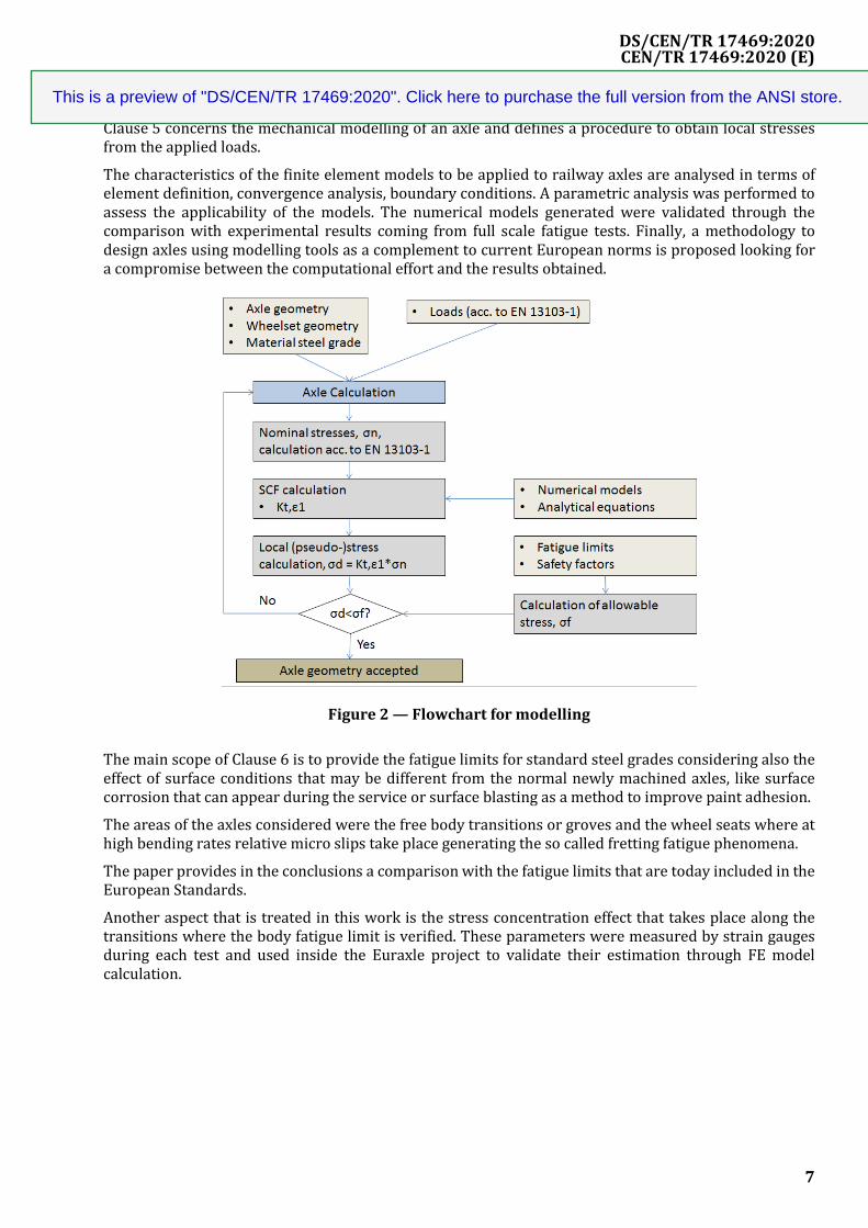
Clause 5 concerns the mechanical modelling of an axle and defines a procedure to obtain local stresses from the applied loads.
The characteristics of the finite element models to be applied to railway axles are analysed in terms of element definition, convergence analysis, boundary conditions. A parametric analysis was performed to assess the applicability of the models. The numerical models generated were validated through the comparison with experimental results coming from full scale fatigue tests. Finally, a methodology to design axles using modelling tools as a complement to current European norms is proposed looking for a compromise between the computational effort and the results obtained.
Figure 2 — Flowchart for modelling
The main scope of Clause 6 is to provide the fatigue limits for standard steel grades considering also the effect of surface conditions that may be different from the normal newly machined axles, like surface corrosion that can appear during the service or surface blasting as a method to improve paint adhesion.
The areas of the axles considered were the free body transitions or groves and the wheel seats where at high bending rates relative micro slips take place generating the so called fretting fatigue phenomena.
The paper provides in the conclusions a comparison with the fatigue limits that are today included in the European Standards.
Another aspect that is treated in this work is the stress concentration effect that takes place along the transitions where the body fatigue limit is verified. These parameters were measured by strain gauges during each test and used inside the Euraxle project to validate their estimation through FE model calculation.
DS/CEN/TR 17469:2020
This is a preview of "DS/CEN/TR 17469:2020". Click here to purchase the full version from the ANSI store.

CEN/TR 17469:2020 (E)
8
Figure 3 — Full-scale and small-scale fatigue tests
DS/CEN/TR 17469:2020
This is a preview of "DS/CEN/TR 17469:2020". Click here to purchase the full version from the ANSI store.
CEN/TR 17469:2020 (E)
9
1 Scope
This document presents the stage of knowledge resulting from the Euraxles project about the design of the axle, and further steps to be taken.
It is the support:
- to define the loads to be taken into account;
- to describe the stress calculation method using finite elements and the validation processes associated;
- to specify the maximum permissible stresses to be assumed in calculations and the safety factors to beused.
This technical report is applicable for:
- wheelset Axles defined in EN 13261 as “pure wheelset”;
- other axle designs such as those encountered in particular rolling stocks e.g. with independent wheels,variable gauges, urban rail…
This document has not for aim to replace EN 13103-1 and CEN/TS 13103-2 but to present a complementary method to the existing ones.
2 Normative references
There are no normative references in this document.
DS/CEN/TR 17469:2020
This is a preview of "DS/CEN/TR 17469:2020". Click here to purchase the full version from the ANSI store.


![ORIENTERING FRA MILJØSTYRELSENS … › wp-content › ... · EU-projekt ”Rivas” [2] har sideløbende arbejdet med vibrationer fra jernbaner. Et andet EU-projekt CargoVibes [3]](https://img.dokumen.tips/doc/110x75/5f0da8da7e708231d43b7353/orientering-fra-miljstyrelsens-a-wp-content-a-eu-projekt-arivasa.jpg)