Embed Size (px)
Citation preview

1
JEOL 2010F operating procedure Covers operation in STEM mode (See separate procedures for operation in TEM mode and operation of EDS system) Nicholas G. Rudawski [email protected] (805) 252-4916 NOTE: this operating procedure assumes the user already has prior experience operating the instrument in TEM mode and is already familiar with the basic operating procedures (loading/unloading, setting eucentric height, etc.). 1. Prior to entering STEM mode
1.1. In regular TEM imaging mode, find a region of interest and set it at eucentric height.
1.2. If necessary, use diffraction mode to align the specimen to a specific crystallographic direction (reset eucentric height afterwards if the specimen tilt was adjusted).
1.3. Make sure the objective and selected area apertures are removed. No
other alignments need to be performed prior to entering STEM mode. 2. Entering STEM mode
2.1. In the FasTEM Client under the “Selector” tab, select “STEM” under “Detector”;
the instrument will enter “AL” alignment mode.
2.2. Retract the C2 aperture (largest dot, bar flipped to the right); you should see a bright focused spot in the middle of an illuminated area on the viewing screen.
2.3. Use the condenser “SHIFT-X” and “SHIFT-Y” controls (L1 and R1 panels) to
center the bright focused spot in the middle of the illuminated area.

2
2.4. In the FasTEM Client under the “Selector” tab, select “SM” to place the instrument in STEM mode; below the ASID monitor, press “SPOT” under “SCAN MODE” to freeze the beam.
Left: “AL” (alignment) mode; right: “SM” (scanning) mode. 3. Probe size selection
3.1. For analytical work: under “Probe Size”, select “1.0nm HR”; this produces a
larger probe with high beam current, which is best for collecting EDS data. For high-resolution imaging: under “Probe Size”, select “0.2nm HR”.
4. Alignment
4.1. Under “Camera Length” select “12 cm”; this will be used for alignment purposes and may be adjusted again later for imaging.
4.2. Observe the Ronchigram on the viewing screen (use the small binoculars). On the “FLC40” control (R1 panel) select “FREE” to activate the free lens control and adjust “COND3” until the rings of Ronchigram converge and the center of

3
the Ronchigram “blows up” (this is most effective when done using an amorphous region); press “FREE” to deactivate the FLC when finished.
Defocused Rough focus
4.3. Activate “ANODE WOBB” (L1 panel) and observe the point of
expansion/contraction relative to the center of the Ronchigram; select “GUN” under “DEFLECTOR” control (R2 panel) and use the “DEF” knobs (R2 panel) so the point of expansion/contraction coincides with the center of the Ronchigram; deactivate “ANODE WOBB” when finished. DO NOT ATTEMPT THIS STEP USING THE DIGITAL CAMERA; YOU WILL DAMAGE THE SCINTILLATOR!
4.4. In Digital Micrograph in “Camera View”, set the “Exposure (s)” to 0.001, select
“Start View” and lift up the viewing screen; the Ronchigram should be visible in the live camera image; center the Ronchigram in the image by selecting “PROJ” under “DEFLECTOR” and using the “SHIFT” knobs (R2 panel).
4.5. Use “OBJ FOCUS” to slightly under focus to see rings in the Ronchigram
(region must be amorphous); select “COND STIG” (L1 panel) and use the “DEF X” and “DEF Y” knobs (L1 and R1 panels) to make the rings in the Ronchigram circular.
Defocused, astigmatic Defocused, corrected Focused, corrected
4
4.6. Under “WOBBLER”, select “COND” (R2 panel, set amplitude = 1 and frequency = 3) and observe the expansion and contraction of the Ronchigram; select “SPOT” (R2 panel) under “DEFLECTOR” and adjust “SHIFT” (R2 panel) so the Ronchigram expands and contracts concentrically; deactivate “COND” under “WOBBLER” (R2 panel) when finished. If the Ronchigram now appears astigmatic, then repeat 4.5.
4.7. Insert the C2 aperture and center it on the Ronchigram; the point of
expansion/contraction in the Ronchigram should be centered in the aperture as the focal condition is changed back and forth from focused to under focused. For analytical work, the 50 or 70 µm C2 aperture should be used, while the 20 µm C2 aperture should be used for high-resolution work. When finished, stop acquiring a live image of the Ronchigram in “Camera View” and flip the viewing screen back down.
5. STEM image acquisition
5.1. Adjust “Camera Length” to be used for imaging. Image contrast will improve
with decreasing camera length, but at the expense of image signal. Camera lengths ≤ 15 cm should be used to form true HAADF-STEM images.
5.2. Make sure “EXT” to the left of the ASID monitor and the two “DFI” buttons under “SSP10” are activated and insert the ADF detector; select “PROJ” under “DEFLECTOR” (R2 panel) and use the “SHIFT” knobs (R2 panel) to center the Ronchigram in the middle of the ADF detector rim.
5.3. Select “PIC” under “SCAN MODE” to start live image acquisition on the ASID
monitor; adjust the “BRIGHTNESS” and “CONTRAST” controls to the right of the ASID monitor to adjust the image so it is satisfactory.
5.4. Prior to attempting to translate the specimen in STEM mode, turn the trackball
control 90° clockwise; the response of the specimen as observed on the ASID monitor will now mimic the movement of the trackball as per TEM mode.
6. Exiting STEM mode
6.1. Press “SPOT” under “SCAN MODE” below the ASID monitor to freeze the beam.
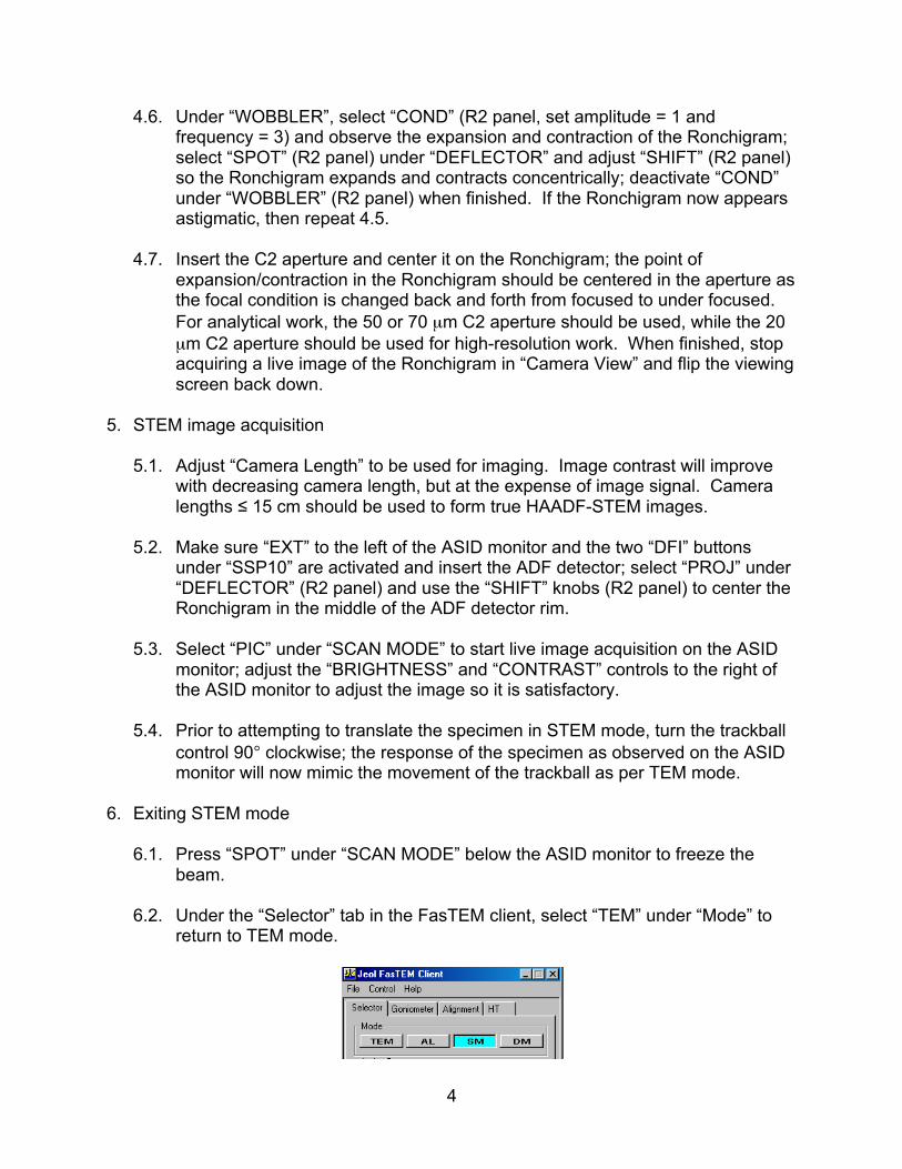
6.2. Under the “Selector” tab in the FasTEM client, select “TEM” under “Mode” to
return to TEM mode.

5
6.3. Retract the ADF detector.
6.4. Make sure the 50 µm C2 aperture is inserted (if the 70 µm C2 aperture was
inserted for analytical work or the 20 µm C2 aperture was used for high-resolution work).
6.5. In Digital Micrograph, go to “Microscope” along the top menu bar and select
“Setup…” from the pull down menu. In the “Microscope Setup” dialogue box that pops up, select “OK” (this returns the calibration state of Digital Micrograph back to TEM mode).
6.6. If you do not plan on doing any TEM imaging and just finishing the session, realign the C2 aperture and gun tilt in TEM mode (these alignments will be very different from STEM mode) and reorient the track ball for TEM mode; if you plan on doing TEM imaging, perform the full TEM mode column alignment.

6
Appendix A: shorthand alignment/imaging instructions
1. Bring specimen to eucentric height in TEM mode 2. Enter AL mode, retract C2 aperture, and center bright focused spot in center of
illuminated area using condenser shift 3. Enter SM mode and go into SPOT mode 4. Select appropriate probe size for application 5. Set camera length to 12 cm for alignment purposes; center the Ronchigram on
the viewing screen with projector shift 6. Activate the FLC40 and blow up the center of the Ronchigram using COND3
(best accomplished on amorphous region); deactivate FLC40 when finished 7. Activate ANODE WOBB and center point of expansion/contraction on middle of
Ronchigram with gun deflectors 8. Set “Exposure (s)” to 0.001 in “Camera View” and start acquiring a live image 9. Lift up viewing screen, center Ronchigram in live image with projector shift 10. Underfocus Ronchigram and use condenser stigmators to make rings circular 11. Activate condenser wobbler; adjust spot shift so Ronchigram expands and
contracts evenly; deactivate condenser wobbler; adjust condenser stigmators again if needed
12. Insert appropriate C2 aperture and center on Ronchigram 13. Lower the viewing screen, insert the ADF detector, select the camera length to
be used for imaging (15 cm at most for a HAADF image), and center the Ronchigram in ADF detector rim with projector shift
14. Enter SCAN mode to start acquiring a live STEM image; adjust contrast and brightness on ASID as necessary
15. Start acquiring a live STEM image in Digital Micrograph © and finely focus the image; acquire a high-quality STEM image when ready
16. Stop acquiring a live STEM image and go into SPOT mode 17. Return to TEM mode, reinsert the 50 µm C2 aperture (if needed), and realign the
C2 aperture and gun tilt