Embed Size (px)
Citation preview

Edition: Final Page 1
4
JARUS CS-LUAS
Recommendations for Certification Specification for Light Unmanned Aeroplane
Systems
DOCUMENT IDENTIFIER : JAR_DEL_WG3_D.04
Edition Number : Edition 0.3
Edition Date : November 2016
Status : Final
Intended for : Publication
Category : WG approved
WG : 3
© NO COPYING WITHOUT JARUS PERMISSION
All rights reserved. Unless otherwise specific, the information in this document may be used but no copy-paste is allowed without JARUS’s permission.

Edition: Final Page 2
DOCUMENT CHARACTERISTICS
TITLE
JARUS CS-LUAS
Recommendations for Certification Specification for Light Unmanned Aeroplane Systems
Publications Reference: JAR_doc_05
ID Number: D.04
Document Identifier Edition Number: 0.3
JAR_DEL_WG3_D.04 Edition Date: 09.11.2016
Abstract
This JARUS-CS-LUAS Recommendation ultimately aims at providing recommendations for States to use for their own national legislation, concerning Certification Specification for Light Unmanned Aircraft Systems. The recommendations presented in this JARUS-CS-LUAS Recommendation document represents the culmination of best practices and procedures used in prior RPAS approvals, as well as input from JARUS-WG-3 (Airworthiness) expert members.
Keywords
Certification, Acceptable Means of Compliance AMC,Emergency Recovery Capability ERC
Contingency Procedures
Contact Person(s) Tel Unit
Markus Farner – Swiss FOCA
JARUS WG-3 Leader +41 58 465 93 67
STATUS, AUDIENCE AND ACCESSIBILITY
Status Intended for Accessible via
Working Draft General Public Intranet
Draft JARUS members Extranet
Proposed Issue Restricted Internet (http://jarus-rpas.org)
Released Issue External consultation Share point

Edition: Final Page 3
DOCUMENT APPROVAL
The following table identifies the process successively approving the present issue of this document before public publication.
PROCESS NAME AND SIGNATURE WG leader DATE
WG Markus Farner 20.11.2015
Internal Consultation Markus Farner 18.08.2016
External Consultation Markus Farner 09.11.2016
Edition: Final Page 4
DOCUMENT CHANGE RECORD
The following table records the complete history of the successive editions of the present document.
EDITION NUMBER
EDITION DATE
REASON FOR CHANGE PAGES AFFECTED
0.1 31.12.2015 First Edition for internal consultation all
0.2 18.08.2015 Changes from internal consultation incorporated all
0.3 09.11.2016 Changes from external consultation all
Edition: Final Page 5
JARUS WG-3 Leader Markus Farner Tel: +41 (0)58 465 93 64 Fax: +41 (0)58 465 80 32 E-mail: [email protected] [email protected] Core Group: Alessandro Adinolfi ANAC Brasil Cristina Angulo EASA Keith Dodson CAA UK Javier Ajo Ortiz ANAC Spain Giovanni Di Antonio ENAC Italy Glen Steemson CASA Australia James Blyn FAA James Foltz FAA George Portwig CAA South Africa Valery Matveev TSAGI Russia Vladimir Shibaev TSAGI Russia Vito Foti ENAC Italy With special contribution from: Ailton Junior ANAC Brasil Angela Rapaccini ENAC Italy Dominique Colin EUROCONTROL Special Tank’s to: Emanuela Innocente JARUS Secretariat Julia Sanchez JARUS Secretariat And thanks’ to the rest of WG-3 coming from all over the world.

Edition: Final Page 6
Table of Contents DOCUMENT CHARACTERISTICS ................................................................................................ 2
DOCUMENT APPROVAL .............................................................................................................. 3
DOCUMENT CHANGE RECORD .................................................................................................. 4
Introduction ..................................................................................................................................... 8
1. Background.............................................................................................................................. 9
1.1 Purpose of the document .................................................................................................. 9
1.2 Status of the document ..................................................................................................... 9
1.3 Glossary ........................................................................................................................... 9
1.4 Recommendations ............................................................................................................ 9
2. Certification Specification for Light Unmanned Aeroplane Systems (CS-LUAS) ..................... 10
2.1 BOOK 1 – Airworthiness Code ........................................................................................ 10
SUBPART A - GENERAL .......................................................................................................... 10
SUBPART B - FLIGHT .............................................................................................................. 10
SUBPART C - STRUCTURE ..................................................................................................... 17
SUBPART D - DESIGN AND CONSTRUCTION ....................................................................... 37
SUBPART E - POWERPLANT .................................................................................................. 46
SUBPART F - EQUIPMENT ...................................................................................................... 63
SUBPART G - OPERATING LIMITATIONS AND INFORMATION ............................................ 74
SUBPART H - DETECT AND AVOID ........................................................................................ 80
SUBPART I - REMOTE PILOT STATION .................................................................................. 80
APPENDIX A - INSTRUCTIONS FOR CONTINUED AIRWORTHINESS .................................. 85
APPENDIX B - ENGINES STRUCTURES ................................................................................. 86
APPENDIX C - INTERACTION OF SYSTEMS AND STRUCTURES ........................................ 92
APPENDIX D - HIRF ENVIRONMENTS AND EQUIPMENT HIRF TEST LEVELS .................... 97
APPENDIX E - MULTI ENGINE RPAS .................................................................................... 100
APPENDIX F - SIMPLIFIED DESIGN LOAD CRITERIA FOR CONVENTIONAL RPA ............ 100
APPENDIX G - SIMPLIFIED CRITERIA FOR CONTROL SURFACE LOADINGS .................. 114
APPENDIX H - LANDING GEAR ............................................................................................. 121
2.2 BOOK 2 – ACCEPTABLE MEANS OF COMPLIANCE ................................................. 127
SUBPART A - GENERAL ........................................................................................................ 127
SUBPART B - FLIGHT ............................................................................................................ 129
SUBPART C - STRUCTURE ................................................................................................... 130
SUBPART D - DESIGN AND CONSTRUCTION ..................................................................... 145
SUBPART E - POWERPLANT ................................................................................................ 152
SUBPART F - EQUIPMENT .................................................................................................... 159
SUBPART G - OPERATING LIMITATIONS AND INFORMATION .......................................... 163
SUBPART H - DETECT AND AVOID ...................................................................................... 163
SUBPART I - REMOTE PILOT STATION ................................................................................ 163

Edition: Final Page 7
AMC APPENDIX A - INSTRUCTIONS FOR CONTINUED AIRWORTHINESS ....................... 166
AMC APPENDIX B - ENGINES ............................................................................................... 167
AMC APPENDIX C - INTERACTION OF SYSTEMS AND STRUCTURES ............................. 174
AMC APPENDIX D - HIRF ENVIRONMENTS AND EQUIPMENT HIRF TEST LEVELS ......... 176
AMC APPENDIX E - MULTI ENGINE RPAS ........................................................................... 176
AMC APPENDIX F - SIMPLIFIED DESIGN LOAD CRITERIA FOR CONVENTIONAL RPA ... 176
AMC APPENDIX G - CONTROL SURFACE LOADINGS ........................................................ 176

Edition: Final Page 8
INTRODUCTION
JARUS is a group of experts coming from National Aviation Authorities (NAAs) from the five continents, EUROCONTROL and the European Aviation Safety Agency (EASA).
Its purpose is to recommend a single set of technical, safety and operational requirements for all aspects linked to the safe operation of Remotely Piloted Aircraft Systems (RPAS). This requires review and consideration of existing regulations and other material applicable to manned aircraft, the analysis of the specific risks linked to RPAS and the drafting of material to cover the unique features of RPAS.
In order to provide a sound and widely supported recommendation to the interested parties, JARUS will publicly consult interested stakeholders from the RPAS market, including Industry, on their draft deliverables. Since JARUS is not developing legally binding or mandatory regulatory material, this consultation is not in replacement of the usual consultation that a country uses in its rulemaking processes. The JARUS consultation is aimed at delivering a better quality, harmonised proposal for regulation. Each State or Regional Organisation will need to decide how to utilise the harmonised provisions developed by JARUS.
The working group Airworthiness, WG3 of JARUS, began work on this document after issuing CS-LURS in October 2013.
CS-LUAS forms recommendations for a Certification Specification for Light Unmanned Aeroplane Systems. In keeping with the JARUS concept of the three RPAS categories “Open”, “Specific” and “Certified”, CS-LUAS is intended to be used for the “Certified” category but some or all may also be used for the “Specific” category depending on the outcome of the Total Hazard and Risk Assessment.
Since the start of the development of this document, the FAA and EASA have begun a rulemaking task to reorganise FAR/CS-23. Through this reorganisation of the current FAR/CS-23, a new concept will be introduced to provide requirements proportionate to the performance, complexity and the type of operation. The certification specification will be rearranged into objective requirements that are design-independent and applicable to the entire range of aeroplanes within FAR/CS-23. In addition, the requirements will be supported by Airworthiness Design Standards where the design-specific details will be captured.
In the later stages of the development of this CS-LUAS, the work of the group was influenced by this FAA/EASA initiative, resulting in more objective requirements in some areas.
As it was not practical to change the complete CS-LUAS in line with this new concept without incurring further delay, it was decided to issue CS-LUAS in its current form. Although not perfect, it is considered appropriate for the majority of fixed wing RPA.
The Appendix E requirements for “Multi Engine RPAS” are therefore postponed to a later issue.
Due to the rapid evolution of RPAS technology, this document will be subject to review and update when appropriate, but a new set of requirements, CS-UAS, will be developed containing the objective requirements, supported by Airworthiness Design Standards.
The future CS-UAS will be much more in line with the new spirit of the reorganisation of certification requirements into design-independent objective requirements. This may lead to the concept of having CS-LURS, CS-LUAS and other acceptable standards as Airworthiness Design Standards in which the differences between the aircraft-types are addressed to support CS-UAS as the objective requirements. This is seen as a logical way forward since there are already some RPAS designs that do not fit into the traditional classification of either fixed-wing or rotary-wing.

Edition: Final Page 9
1. Background
1.1 Purpose of the document
CS-LUAS are recommendations for Certification Specification for Light Unmanned Aeroplanes.
1.2 Status of the document
It was not practical to change the complete CS-LUAS in line with this new concept of the performance based requirements for FAR/CS-23 without incurring further delay, it was decided to issue CS-LUAS in its current form. Although not perfect, it is considered appropriate for the majority of fixed wing RPA. See the introduction above for more information.
1.3 Glossary
A glossary providing all abbreviations and definitions is provided as a separate document.
1.4 Recommendations
Recommendation using the operative verb shall indicate that they must be implemented to provide conformity with this recommendation.
Recommendation using the operative verb should indicate that they are recommended to achieve the best possible implementation of this recommendation.
Recommendation using the operative verb may indicate options.
Guidelines using the operative verb shall indicate that they must be implemented to achieve the minimum objectives of this guidance material.
Guidelines using the operative verb should indicate that they are recommended to achieve the best possible implementation of this guidance material.
Guidelines using the operative verb may indicate options.

Edition: Final Page 10
2. Certification Specification for Light Unmanned Aeroplane Systems (CS-LUAS)
2.1 BOOK 1 – Airworthiness Code
SUBPART A - GENERAL
CS-LUAS.1 Applicability (See AMC CS-LUAS.1)
a) Depending on the risk of the intended operation, this airworthiness code is applicable, as a whole or in part, to fixed wing Remotely Piloted Aircraft (RPA, with a Maximum Certificated Take-off Weight (MTOW) not exceeding 750 kg.
b) For RPAS with a conventional design, alternative requirements can be applied. c) Within the current CS-LUAS, a Light Unmanned Aircraft System Type Design is defined as a
single Aircraft controlled by a single Control System.
d) In operational terms, applicability of this airworthiness code excludes all human transport and flight into known icing conditions.
e) CS-LUAS covers the requirements for BVLOS operation with the exception that the requirements for any detect and avoid technology ensuring safe separation are not yet developed.
f) For the purpose of CS-LUAS, multi engine RPAS which are not able to meet the multi engine requirements of Appendix E, to maintain the continued safe flight and landing after a single engine failure shall be considered as a single engine RPAS for compliance demonstration.
SUBPART B - FLIGHT
GENERAL
CS LUAS.21 Proof of compliance
(AMC-LUAS.21)
(a) Each requirement of this subpart must be met at each appropriate combination of weight and centre of gravity within the range of loading conditions for which certification is requested. This must be shown –
1) By tests upon an RPA of the type for which certification is requested, or by calculations based on,
and equal in accuracy to, the results of testing; and
2) By systematic investigation of each required combination of weight and centre of gravity, if
compliance cannot be reasonably inferred from combinations investigated.

Edition: Final Page 11
CS-LUAS. 23 Approved Operational Envelope
(See AMC CS-LUAS.23)
The applicant must determine the boundaries of the approved operational envelope within which safe flight, under normal and emergency conditions, and emergency recovery capabilities will be demonstrated.
In determining this envelope, the applicant must consider environmental conditions such as wind speed, light conditions etc.
The Operational Flight Envelope must be protected with a flight envelop protection system in accordance with CS-LUAS.1329 to prevent intentionally exceeding the operational flight envelope.
CS-LUAS.24 Transportation, reconfiguration and storage Envelopes
(a) Where a RPA System or part of the System is designed to be transportable by any means during normal operations or System use, the applicant must determine the boundaries of the transportation and storage envelopes.
(b) Where a RPA System or part of the System is disassembled or reconfigured for transportation, it shall be shown that the expected number of disassembling/assembling or reconfigurations in any System life cycle will not adversely affect the ability to comply with the requirements of CS-LUAS.
(c) In determining these envelopes, the applicant must consider environmental conditions such as wind speed, light conditions etc. as well as shock, vibration, water and moisture, particulate matter, electromagnetic, thermal, and other foreseeable conditions or effects likely to be encountered during transportation or storage.
(d) No environmental factors associated with the means of transportation, reconfiguration and storage shall adversely affect the ability to comply with the requirements of CS-LUAS.
(e) The instruction for transportation, disassembling/assembling or reconfiguration and storage and the respective handling must be prepared in accordance with Appendix A.
CS LUAS.25 Weight limits
(a) Maximum weight. The maximum weight is the highest weight at which compliance with each applicable requirement of this CS-LUAS is shown. The maximum weight must be established so that it is not more than –
(1) The highest weight selected by the applicant;
(2) The design maximum weight, which is the highest weight at which compliance with each applicable structural loading condition of this CS-LUAS is shown
(b) Minimum weight. The minimum weight is the lowest weight at which compliance with each applicable requirement of this CS-LUAS is shown. The minimum weight must be established as Not less than--
(1) The lowest weight selected by the applicant;
(2) The design minimum weight (the lowest weight at which compliance with each applicable
structural loading condition of this Part is shown); or
(3) The empty weight determined under CS-LUAS.29.
CS LUAS.27 Load distribution limits
Ranges of weight and centres of gravity within which the RPA may be safely operated must be established and must include the range of lateral centres of gravity if possible loading conditions can result in significant variation of their positions.

Edition: Final Page 12
CS LUAS.29 Empty weight and corresponding centre of gravity
(a) The empty weight and corresponding centre of gravity must be determined by weighing the RPA
without payload, but with –
(1) Fixed ballast;
(2) Unusable fuel determined under CS LUAS.959
(3) Batteries installed; and
(4) Full operating fluids, including -
(i) Oil;
(ii) Hydraulic fluid; and
(iii) Other fluids required for normal operation of RPA systems.
(b) The condition of the RPA at the time of determining empty weight must be one that is well defined
and can be easily repeated
CS LUAS.33 Propeller speed and pitch limits
(a) Propeller speed and pitch must be limited to values that ensure safe operation under normal operating
conditions.
(b) Propellers that cannot be controlled in flight must meet the following requirements:
(1) During take-off and initial climb within the operational flight envelope, the propeller must limit the
engine rotational speed at full throttle to a value not greater than the maximum allowable take-off
rotational speed, and
(2) During a glide within the operational flight envelope with throttle closed or the engine inoperative,
provided this has no detrimental effect on the engine, the propeller must not permit the engine to
achieve a rotational speed greater than 110% of the maximum continuous speed.
(c) A propeller that can be controlled in flight but does not have constant speed controls must be so
designed that –
(1) Sub-paragraph (b)(1) is met with the lowest possible pitch selected, and (2) Sub-paragraph (b)(2) is
met with the highest possible pitch selected.
(d) A controllable pitch propeller with constant speed controls must comply with the following
requirements:
(1) With the governor in operation, there must be a means to limit the maximum engine rotational
speed to the maximum allowable take-off speed, and
(2) With the governor inoperative, there must be a means to limit the maximum engine rotational
speed to 103% of the maximum allowable take-off speed with the propeller blades at the lowest
possible pitch and the RPA stationary with no wind at full throttle position
PERFORMANCE
CS LUAS.45 General
Unless otherwise prescribed, the performance requirements of this Subpart must be met for still air and standard atmosphere appropriate for the operational envelope in accordance with CS-LUAS.23.

Edition: Final Page 13
CS-LUAS.50 Demonstrated Flight Envelope General
(AMC CS-LUAS.50)
(a) The Demonstrated Flight Envelope must be defined and consists of the operational flight envelope as defined in CS-LUAS.23 supplemented by a safety margin, agreed by the authority.
(b) The Demonstrated Flight Envelope must be demonstrated by flight-test (c) The Demonstrated Flight Envelope must be inside the Flight Envelope defined by CS-LUAS.333
CS-LUAS.53 Flight Performance
(AMC-LUAS.53)
The following information must be determined and provided in the approved Flight Manual:
(a) In take-off configuration at maximum weight within the operational flight envelope established for take-off:
(1) The rotation speed VR, except for catapult assisted or rocket assisted take-off and hand launched RPA
(2) The obstacle clearance height, agreed by the authority (3) The distance required to take-off and climb to the obstacle clearance height (4) The minimum speed at the obstacle clearance height
(b) The horizontal distance required to land and come to a complete stop, or satisfactory low speed for water operation, from the obstacle clearance height above the landing surface
(c) The steady gradient of climb, as agreed by the authority, with not more than maximum continuous power in the configuration applicable for the phase of flight at maximum take-off weight
(d) Except where a RPA is designed to be recovered by parachute, the steady gradient of climb as agreed by the authority, following a balked landing without changing the configuration of the RPA
(e) The minimum balked landing height, as the minimum height above the ground where a successful balked landing could be performed safely.
(f) The maximum range travelled in still air, in km per 1000 m (nautical miles per 1 000 ft) of altitude lost in a descent, and the speed necessary to achieve this, must be determined with the RPA in the most favourable configuration: (1) For a RPA with a single engine, with the engine inoperative.
(2) For multi engine RPAS which do not meet the multi engine requirements of Appendix E with
the most critical engine inoperative.
STABILITY
CS.LUAS.171 General
See AMC LUAS.171
(a) The RPA, augmented by the FCS including all degraded modes, and including the effects of sensor and
computational errors and delays must be longitudinally, directionally and laterally stable in any
condition normally encountered in service, at any combination of weight and center of gravity for
which certification is requested.
(b) Transient response in all axes during transition between different flight conditions and flight modes
must be smooth, convergent, and exhibit damping characteristics with minimal overshoot of the
intended flight path.
(c) In addition to data obtained by computation or modelling, stability analysis must be supported by the
results of relevant flight tests.

Edition: Final Page 14
CS LUAS.201 Wings level and turning flight control
(AMC LUAS.201)
(a) For an RPA with independently controlled roll and directional controls, it must be possible to produce
and to correct roll by unreversed use of the rolling control and to produce and to correct yaw by
unreversed use of the directional control, within the complete demonstrated flight envelope in
accordance with CS-LUAS.50
(b) For an RPA with interconnected lateral and directional controls (2 controls) and for an RPA with only
one of these controls, it must be possible to produce and correct roll by unreversed use of the rolling
control without producing excessive yaw, within the complete demonstrated flight envelope in
accordance with CS-LUAS.50.
CS-LUAS.204 Stall protection in wing level and turning flight
(a) Flight tests shall be conducted in straight flight and in the maximum bank angle in accordance with the
demonstrated flight envelope for each relevant RPA flaps configuration (if flaps are installed) for the
most unfavorable combination of weight, center of gravity and engine setting while abruptly reducing
speed command as per relevant flight control mode.
(b) During these tests, it should be shown that,
(1) The steady speed achieved should remain greater than or equal to the minimum steady flight
speed (except take-off and landing) in accordance with the demonstrated flight envelope.
(2) No unsafe characteristics occur.
GROUND HANDLING CHARACTERISTICS
CS-LUAS 231 Longitudinal stability and control
(a) A landplane may have no uncontrollable tendency to nose over in any reasonably expected operating
condition, including rebound during landing or take-off. Wheel brakes must operate smoothly and may
not induce any undue tendency to nose over.
(b) A seaplane or amphibian may not have dangerous or uncontrollable porpoising characteristics at any
normal operating speed on the water.
CS LUAS.233 Directional stability and controllability
(a) A 90° cross-component of wind velocity, demonstrated to be safe for taxiing, take-off and landing must
be established.
(b) A landplane must be satisfactorily controllable, without exceptional piloting skill or alertness when
under direct remote pilot control, in power-off landings at normal landing speed.
(c) The aeroplane must have adequate directional control during taxiing.
(d) Seaplanes must demonstrate satisfactory directional stability and controllability for water operations
up to the maximum wind velocity specified in sub-paragraph (a).
CS-LUAS 235 Ground Operation
The shock-absorbing mechanism may not damage the structure of the RPA when the aeroplane is operated on the roughest ground that may reasonably be expected in normal operation.

Edition: Final Page 15
MISCELLANEOUS FLIGHT REQUIREMENTS
CS-LUAS.251 Vibration and Buffeting
There must be no vibration or buffeting severe enough to result in structural damage and each part of the RPA must be free from excessive vibration, under any appropriate speed and power or thrust conditions up to at least the minimum value of VD allowed in CS-LUAS.335. In addition there must be no vibration or buffeting in any normal flight condition severe enough to interfere with the satisfactory control of the RPA
CS-LUAS.253 High Speed Characteristics
(AMC CS-LUAS.253)
A safe return from inadvertent speed increases above the extremes of the operational flight envelope that may be encountered in all operating modes must be demonstrated.
CATAPULT ASSISTED AND ROCKET ASSISTED TAKE-OFF RPA
CS-LUAS.280 Launch performance
(a) The RPA must achieve sufficient energy and controllability at the end of the launch phase to ensure
safe and controllable fly-away under the most adverse combination of environmental and operating
conditions.
The launch phase ends when the RPA leaves the flight safety area associated to the launch safety area
required in CS-LUAS.283.
(b) The launch performance (launch parameters settings, launch speed) must be determined for each
weight, altitude, temperature and wind condition within the operational limits established for take-off
in addition to requirement specified in CS-LUAS.53.
(c) It must be shown by test that the acceleration sustained by the RPA during the launch phase does not
lower RPA engine performance in a manner that could be inadequate for safe operation
(d) A manual abort function must be easily accessible to the RPA crew in order to cancel the RPA launch at
any time before the irreversible catapult or rocket ignition phase.
CS-LUAS.281 Transition to normal flight attitude
(a) The transition to normal flight attitude or normal in-flight RPA configuration must be such that no
possibility of conflict exists between the RPA and its launch platform or any other object under any
combination of environmental conditions.
(b) The RPA must remain in a predictable flight condition that does not exhibit any tendencies to depart
from controlled flight throughout the launch phase.

Edition: Final Page 16
CS-LUAS.282 RPA active control
In case of launch without active control of the RPA attitude or direction by the flight control system, the RPA must not diverge beyond its recoverable limit and the active control must be engaged before the RPA reaches the boundary of its launch safety area.
CS-LUAS.283 Launch safety area
(See AMC-LUAS.283)
A launch safety area is defined as a predetermined geometrical area in which the RPA remains after a failure or malfunction in the catapult- or rocket- launch phase.
a) The limits of the launch safety area around the launch platform must be determined for each weight, altitude, wind conditions, and temperature within the operational limits established for take-off.
b) The size and shape of this launch safety area shall be stated in the RPA System Flight Manual and calculated under any combination of environmental and operational conditions.
PARACHUTE LANDING SYSTEM
CS-LUAS.290 RPA performance before parachute landing
(a) The RPA flight performance and control characteristics must be adequate for all intended parachute landing procedure under all specified operational conditions.
(b) Two modes of landing by parachute can be foreseen: 1) As a normal landing mode where a parachute is used in a regular way after every flight, and, 2) As an emergency recovery capability according CS-LUAS.1412.
(c) It must be possible to abort the normal landing procedure at any point prior to the initiation of the final deployment sequence and it must be shown that a safe transition to a normal flight mode or go around conditions can be made.
(d) The normal and emergency parachute landing sequence must be precisely defined in the RPA System Flight Manual including for normal landing the approach phase and the go around procedure.
CS-LUAS.291 Parachute landing characteristics
(a) The normal landing under parachute must be made without excessive vertical acceleration or tendency to bounce, nose over, ground loop or porpoise.
(b) The minimum parachute safety height must ensure a correct parachute deployment sequence and must ensure that the RPA descent under a fully inflated parachute is stabilised whatever the combination of environmental conditions (e.g. weight, altitude, wind, temperature etc).
(c) The parachute must be deployed at a height greater or equal to the minimum parachute safety height above ground, which depends on the timing of the parachute sequence.
(d) The minimum parachute safety height must be determined and stated in the RPA System Flight Manual.
CS-LUAS.292 Parachute landing performance
(a) The normal parachute landing must be designed to ensure the landing inside a predetermined geometrical area. The size and shape of this area shall be stated in the RPA System Flight Manual and calculated under any combination of environmental and operational conditions.
(b) It must be shown that the parachute landing sequence is a reliable, repeatable and predictable safe operation 1) at every combination of weight and balance of the RPA for which certification is requested,

Edition: Final Page 17
2) in the most adverse weather conditions (wind, rain, icing, …) for which approval is requested, 3) throughout the life cycle of the RPA System.
(c) The features of the terrain over which the parachute landing can be performed in normal condition must be stated in the RPA System Flight Manual, in particular its acceptable slope
SUBPART C - STRUCTURE
GENERAL
CS-LUAS.301 Loads
(a) Strength requirements are specified in terms of limit loads (the maximum loads to be expected in
service) and ultimate loads (limit loads multiplied by prescribed factors of safety). Unless otherwise
provided, prescribed loads are limit loads.
(b) Unless otherwise provided, the air, ground and water loads must be placed in equilibrium with inertia
forces, considering each item of mass in the aeroplane. These loads must be distributed to
conservatively approximate or closely represent actual conditions. Methods used to determine load
intensities and distribution on canard and tandem wing configurations must be validated by flight test
measurement unless the methods used for determining those loading conditions are shown to be
reliable or conservative on the configuration under consideration.
(c) If deflections under load would significantly change the distribution of external or internal loads, this
redistribution must be taken into account.
(d) Simplified structural design criteria may be used for conventional RPA according CS-LUAS.1, if they
result in design loads not less than those prescribed in CS-LUAS.331 to LUAS.521.
For conventional RPA, the design criteria of Appendix F of CS-LUAS are an approved equivalent of CS-LUAS.321 to LUAS.459. If Appendix F is used, the entire Appendix must be substituted for the corresponding paragraphs of this CS-LUAS.
CS-LUAS.302 Interaction of systems and structures
(see Appendix C)
For RPAS equipped with systems that affect structural performance, either directly or as a consequence of a failure or malfunction, the influence of these systems and their failure conditions must be taken into account when showing compliance with the requirements of Subparts C and D. Appendix C of CS-LUAS must be used to evaluate the structural performance of the RPAS equipped with these systems.
CS-LUAS.303 Factor of safety
Unless otherwise provided, a factor of safety of 1·5 must be used.
CS-LUAS.305 Strength and deformation
(a) The structure must be able to support limit loads without detrimental, permanent deformation. At
any load up to limit loads, the deformation may not interfere with safe operation.

Edition: Final Page 18
(b) The structure must be able to support ultimate loads without failure for at least three seconds, except
local failures or structural instabilities between limit and ultimate load are acceptable only if the
structure can sustain the required ultimate load for at least three seconds. However, when proof of
strength is shown by dynamic tests simulating actual load conditions, the three second limit does not
apply.
CS-LUAS.307 Proof of structure
(See AMC LUAS.307)
(a) Compliance with the strength and deformation requirements of CS LUAS.305 must be shown for each
critical load condition. Structural analysis may be used only if the structure conforms to those for
which experience has shown this method to be reliable. In other cases, substantiating load tests must
be made. Dynamic tests, including structural flight tests, are acceptable if the design load conditions
have been simulated.
(b) Certain parts of the structure must be tested as specified in Subpart D of CS-LUAS.
CS LUAS.309 Canard or tandem wing configurations
The forward structure of a canard or tandem wing configuration must –
(a) Meet all requirements of subpart C and subpart D of CS-LUAS applicable to a wing; and
(b) Meet all requirements applicable to the function performed by these surfaces.
FLIGHT LOADS
CS-LUAS.321 General
(See AMC LUAS.321 (c))
(a) Flight load factors represent the ratio of the aerodynamic force component (acting normal to the
assumed longitudinal axis of the aeroplane) to the weight of the aeroplane. A positive flight load
factor is one in which the aerodynamic force acts upward, with respect to the aeroplane.
(b) Compliance with the flight load requirements of this subpart must be shown –
(1) At each critical altitude within the range in which the aeroplane may be expected to operate;
(2) At each weight from the design minimum weight to the design maximum weight; and
(3) For each required altitude and weight, for any practicable distribution of disposable load within
the operating limitations specified in CS LUAS.1583 to LUAS.1589.
(c) When significant the effects of compressibility must be taken into account.
CS LUAS.331 Symmetrical flight conditions
(a) The appropriate balancing tail load must be accounted for in a rational or conservative manner when
determining the wing loads and linear inertia loads corresponding to any of the symmetrical flight
conditions specified in CS LUAS.331 to LUAS.341.
(b) The incremental horizontal tail loads due to maneuvering and gusts must be reacted by the angular
inertia of the RPA in a rational or conservative manner.
(c) Mutual influence of the aerodynamic surfaces must be taken into account when determining flight
loads.

Edition: Final Page 19
CS LUAS.333 Flight envelope
(a) General. Compliance with the strength requirements of this subpart must be shown at any
combination of airspeed and load factor on and within the boundaries of a flight envelope (similar to
the one in sub-paragraph (d) ) that represents the envelope of the flight loading conditions specified
by the manoeuvring and gust criteria of sub-paragraphs (b) and (c) respectively.
(b) Manoeuvring envelope. Except where limited by maximum (static) lift coefficients, the aeroplane is
assumed to be subjected to symmetrical manoeuvres resulting in the following limit load factors:
(1) The positive manoeuvring load factor specified in CS LUAS.337 at speeds up to VD;
(2) The negative manoeuvring load factor specified in CS LUAS.337 at VC; and
(3) Factors varying linearly with speed from the specified value at VC to 0·0 at VD for the normal
category, and -1·0 at VD for the aerobatic categories.
(c) Gust envelope
(1) The RPA is assumed to be subjected to symmetrical vertical and lateral gusts in level flight.
The resulting limit load factors must correspond to the conditions determined as follows:
(i) Positive (up) and negative (down) gusts of 50 fps at VC must be considered at altitudes
between sea level and 6096 m (20 000 ft). The gust velocity may be reduced linearly from 50
fps at 6096 m (20 000 ft) to 25 fps at 15240 m (50 000 ft); and
(ii) Positive and negative gusts of 25 fps at VD must be considered at altitudes between sea
level and 6096 m (20 000 ft). The gust velocity may be reduced linearly from 25 fps at 6096 m
(20 000 ft) to 12·5 fps at 15240 m (50 000 ft).
(2) The following assumptions must be made:
(i) The shape of the gust is –
where –
s = Distance penetrated into gust (ft.);
C= Mean geometric chord of wing (ft.); and
Ude = Derived gust velocity referred to in sub-paragraph (1) linearly with speed between VC and VD.
(ii) Gust load factors vary linearly with speed between VC and VD.
(d) Flight envelope

Edition: Final Page 20
Note: Point G need not be investigated when the supplementary condition specified in CS LUAS.369 is investigated.
CS-LUAS.335 Design Airspeeds
The selected airspeeds are equivalent airspeeds (EAS).
(a) Design cruising speed, VC. For VC, the following apply
(1) VC shall be defined according to RPA operating requirements.
(2) At altitudes where an MD is established, a cruising speed MC limited by compressibility may be selected.
(b) Design dive speed, VD. For VD the following apply:
(1)VD/MD may not be less than 1.25 VC/MC.
(c) Design manoeuvring speed VA. For VA, the following applies:
(1) VA may not be less than VS.n1/2 where
(i) VS is a computed stalling speed with flaps retracted at the design weight, normally based on the maximum UAV normal force coefficients, CNA; and
(ii) n is the limit manoeuvring load factor used in design and specified at CS-LUAS.337.
(2) The value of VA need not exceed the value of VC used in design.
CS-LUAS.337 Limit Manoeuvring Load Factors
(a) The minimum positive limit manoeuvring load factor n is the minimum of 2.1 + 10900/(W+4536)
(where W = design maximum take-off weight in kg) or 3.8;
(b) The negative limit manoeuvring load factor may not be less than 0.4 times the positive load factor
(c) Manoeuvring load factors lower than those specified in this section may be used if the UAV has design
features that make it impossible to intentionally exceed these values in flight.

Edition: Final Page 21
CS-LUAS.341 Gust Load Factors
See AMC LUAS.341
(a) Each RPA must be designed for loads on each lifting surface resulting from gusts specified in CS-
LUAS.333(c).
(b) The gust load for a canard or tandem wing configuration must be computed using a rational analysis.
CS LUAS.343 Design fuel loads
(See AMC 23.343 (b))
(a) The disposable load combinations must include each fuel load in the range from zero fuel to the selected maximum fuel load.
(b) If fuel is carried in the wings, the maximum allowable weight of the aeroplane without any fuel in the wing tank(s) must be established as “maximum zero wing fuel weight” if it is less than the maximum weight.
CS LUAS.345 High lift devices
(See AMC 23.345 (d))
(a) If flaps or similar high lift devices are to be used for take-off, approach or landing, the aeroplane, with the flaps fully extended at VF, is assumed to be subjected to symmetrical manoeuvres and gusts within the range determined by – (1) Manoeuvring, to a positive limit load factor of 2·0; and (2) Positive and negative gust of 7.62 m (25 ft) per second acting normal to the flight path in level
flight. (b) VF must be assumed to be not less than 1·4 VS or 1·8 VSF, whichever is greater, where—
(1) VS is the computed stalling speed with flaps retracted at the design weight; and (2) VSF is the computed stalling speed with flaps fully extended at the design weight.
However, if an automatic flap load limiting
device is used, the aeroplane may be designed
for the critical combinations of airspeed and flap
position allowed by that device.
(c) In determining external loads on the aeroplane as a whole, thrust, slip-stream and pitching acceleration may be assumed to be zero.
(d) The flaps, their operating mechanism and their supporting structures, must be designed for the conditions prescribed in subparagraph (a). In addition, with the flaps fully extended at speed VF the following conditions, taken separately, must be accounted for: (1) A head-on gust having a velocity of 7.6 m (25 ft) per second (EAS), combined with propeller
slipstream corresponding to 75% of maximum continuous power; and (2) The effects of propeller slipstream corresponding to maximum take-off power.
CS LUAS.347 Asymmetrical Flight Conditions
The RPA is assumed to be subjected to the asymmetrical flight conditions of CS-LUAS.349 and CS-LUAS.351. Unbalanced aerodynamic moments about the centre of gravity must be reacted in a rational or conservative manner, considering the principal masses furnishing the reacting inertia forces.

Edition: Final Page 22
CS-LUAS 349 Rolling conditions
The wing and wing bracing must be designed for the following loading conditions:
(a) Unsymmetrical wing loads. Unless the following values result in unrealistic loads, the rolling accelerations may be obtained by modifying the symmetrical flight conditions in CS-LUAS 333(d) as follows: In condition A, assume that 100% of the semispan wing airload acts on one side of the aeroplane and 70% of this load acts on the other side.
(b) The loads resulting from the aileron deflections and speeds specified in CS-LUAS 455, in combination with an aeroplane load factor of at least two thirds of the positive manoeuvring load factor used for design. Unless the following values result in unrealistic loads, the effect of aileron displacement on wing torsion may be accounted for by adding the following increment to the basic aerofoil moment coefficient over the aileron portion of the span in the critical condition determined in CS-LUAS 333 (d); ΔCm = − 0.01δ
where –
ΔCm is the moment coefficient increment;
And
δ is the down aileron deflection in degrees in the critical condition.
CS-LUAS.351 Yawing Conditions
The UAV must be designed for yawing loads on the tail surfaces resulting from the loads specified in CS LUAS.441 to CS-LUAS.445.
CS-LUAS.361 Engine Torque
(a) The mounting arrangement for each engine and its supporting structure must be designed for the
effects of
(1) A limit engine torque corresponding to take-off power or thrust and propeller speed acting
simultaneously with 75% of the limit loads from flight condition A of CS-LUAS.333 (d);
(2) A limit engine torque corresponding to maximum continuous power or thrust and propeller
speed acting simultaneously with the limit loads from flight condition A of LUAS.333 (d); and
(3) For turbo-propeller installations, in addition to the conditions specified in sub-paragraphs (a) (1)
and (a) (2) of this paragraph, a limit engine torque corresponding to take-off power or thrust and
propeller speed, multiplied by a factor accounting for propeller control system malfunction,
including quick feathering, acting simultaneously with 1g level flight loads. In the absence of a
rational analysis, a factor of 1.6 must be used.
(b) For turbine-engine installations, the mounting arrangement for each engine and supporting structure
must be designed to withstand each of the following:
(1) A limit engine torque load imposed by sudden engine stoppage due to malfunction or structural
failure (such as compressor jamming); and
(2) A limit engine torque load imposed by the maximum acceleration of the engine.

Edition: Final Page 23
(c) The limit engine torque to be considered under sub-paragraph (a) of this paragraph must be obtained
by multiplying the mean torque by a factor of
(1) 1.25 for turbo-propeller installations;
(2) 1.33 for engines with five or more cylinders; and
(3) Two, three, or four, for engines with four, three or two cylinders, respectively.
(4) 1.33 for Wankel engine
(d) For electrical engines: the maximum peak torque to be expected in the complete engine speed range.
CS-LURS.363 Sideload On Engine Mount
(a) The mounting arrangement for each engine and its supporting structure must be designed for a limit
load factor in a lateral direction, for the sideload on the engine mount, of not less than:
(1) 1.33; or
(2) One-third of the limit load factor for flight condition A.
(b) The sideload prescribed in sub-paragraph (a) of this paragraph may be assumed to be independent of
other flight conditions.
CS-LUAS.365 Pressurised Compartment Loads
For each pressurised compartment, the following apply:
(a) The UAV structure must be strong enough to withstand the flight loads combined with pressure
differential loads from zero up to the maximum relief valve setting.
(b) The external pressure distribution in flight and any stress concentrations, must be accounted for.
(c) If landings may be made, with the compartment pressurised, landing loads must be combined with
pressure differential loads from zero up to the maximum allowed during landing.
(d) The UAV structure must be strong enough to withstand the pressure differential loads corresponding
to the maximum relief valve setting multiplied by a factor of 1.33 omitting other loads.
(e) If a pressurised compartment has two or more compartments, separated by bulkheads or a floor, the
primary structure must be designed for the effects of sudden release of pressure in any compartment
with external opening . This condition must be investigated for the effects of failure of the largest
opening in the compartment. The effects of intercompartmental venting may be considered.
CS-LUAS.367 Asymmetrical Loads Due to Engine Failure
(a) The RPA must be designed for the asymmetrical loads resulting from the failure of the critical engine.
Turbopropeller RPA must be designed for the asymmetrical loads resulting from the failure of the
critical engine including the following conditions in combination with a single malfunction of the
propeller drag limiting system,
(1) At speeds between VMC and VD, the loads resulting from power failure because of fuel flow
interruption are considered to be limit loads;
(2) At speeds between VMC and VC, the loads resulting from the disconnection of the engine
compressor from the turbine or from loss of the turbine blades are considered to be ultimate
loads;

Edition: Final Page 24
(3) The time history of the thrust decay and drag build-up occurring as a result of the prescribed
engine failures must be substantiated by test or other data applicable to the particular engine-
propeller combination; and
(b) The timing and magnitude of the probable pilot or automated corrective action must be
conservatively estimated, considering the characteristics of the particular engine-, propeller-,
aeroplane- combination..
(c) In case of no automatically performed corrective action, Pilot corrective action, may be assumed to be
initiated at the time maximum yawing velocity is reached, but not earlier than 2 seconds after the
engine failure.
CS-LUAS.369 Rear lift truss
(a) If a rear lift truss is used, it must be designed for conditions of reversed airflow at a design speed of –
V = 8·7 (W/S)1/2 + 8·7(knots) where W/S = wing loading at design maximum take-off weight (lb/ft2).
(b) Either aerodynamic data for the particular wing section used, or a value of CL equalling -0·8 with a
chordwise distribution that is triangular between a peak at the trailing edge and zero at the leading
edge, must be used.
CS LUAS.371 Gyroscopic and aerodynamic loads
(See AMC LUAS.371 and 371(a) )
(a) Each engine mount and its supporting structure must be designed for the gyroscopic, inertial and
aerodynamic loads that result, with the engine(s) and propeller(s), if applicable at maximum
continuous rpm, under either –
(1) The conditions prescribed in CS LUAS.351 and LUAS.423; or
(2) All possible combinations of the following in the limits allowed by the flight control
system:
(i) a yaw velocity of 150% of the maximum predicted yaw rotational velocity within
the flight envelope maintained by the flight control system
(ii) a pitch velocity of 150% of the maximum predicted pitch rotational velocity within
the flight envelope maintained by the flight control system;
(iii) a normal load factor of 150% of the maximum predicted load factor within the
flight envelope maintained by the flight control system; and
(iv) Maximum continuous thrust.
CS LUAS.373 Speed control devices
If speed control devices (such as spoilers and drag flaps) are incorporated for use in en-route conditions –
(a) The aeroplane must be designed for the symmetrical manoeuvres and gusts prescribed in CS
LUAS.333, LUAS.337 and LUAS.341 and the yawing manoeuvres and lateral gusts in CS LUAS.441 and
LUAS.443, with the device extended at speeds up to the placard device extended speed; and
(b) If the device has automatic operating or load limiting features, the aeroplane must be designed for
the manoeuvre and gust conditions prescribed in sub-paragraph (a) at the speeds and corresponding
device positions that the mechanism allows.

Edition: Final Page 25
PARACHUTE DEPLOYMENT LOADS
CS-LUAS.380 Parachute loads in normal landing conditions
The loads during recovery phase due to deployment of the parachute and consequent aerodynamic and inertial loads from the worst operational condition of weight and flight envelope must be determined.
CS-LUAS.382 Parachute loads in emergency landing conditions
For applications in which parachute recovery is an emergency condition only, the loads due to deployment of the parachute and consequent aerodynamic and inertial loads from the worst operational condition of weight and flight envelope must be considered as an ultimate condition only.
CONTROL SURFACE AND SYSTEM LOADS
CS LUAS.391 Control surface loads
(See AMC LUAS.391(b) )
(a) The control surface loads specified in CS LUAS.405 to LUAS.459 are assumed to occur in the
conditions described in CS LUAS.331 to LUAS.351.
(b) For conventional RPA, if allowed by the following paragraphs, the values of control surface loading in
Appendix G may be used, instead of particular control surface data, to determine the detailed rational
requirements of CS-LUAS.395 to CS-LUAS.459, unless –
(1) the RPA has high-performances, (2) the spar configurations are located aft of the 25% chord length, (3) the horizontal stabilizer leading edges are not attached at the fuselage, (4) the experience shows these criteria give inappropriate surface loading for the RPA configuration,
or
(5) these values result in unrealistic loads.
CS LUAS.393 Loads parallel to hinge line
(See AMC LUAS.393 (a) and AMC LUAS.393 (b))
(a) Control surfaces and supporting hinge brackets must be designed to withstand inertial loads acting
parallel to the hinge line.
(b) In the absence of more rational data, the inertia loads may be assumed to be equal to KW, where –
(1) K = 24 for vertical surfaces;
(2) K = 12 for horizontal surfaces; and
(3) W = weight of the movable surfaces.

Edition: Final Page 26
CS LUAS.395 Control system loads
(a) Each flight control system and its supporting structure must be designed for loads corresponding to at
least 125% of the computed hinge moments of the movable control surface in the conditions
prescribed in LUAS.391 to LUAS.459.
In addition, the following apply:
(1) The system limit loads are the maximum loads that can be produced by the automatic devices
operating the controls. The effect of the tabs must be taken into account.
(2) The design must, in any case, provide a rugged system for service use, considering jamming,
ground gusts, taxiing downwind, control inertia and friction.
(b) A 125% factor on computed hinge movements must be used to design elevator, aileron and rudder
systems. However, a factor as low as 1.0 may be used if hinge moments are based on accurate flight
test data, the exact reduction depending upon the accuracy and reliability of the data.
(c) Forces occurring from the actuating system are assumed to act at the appropriate attachments of the
control system to the control surface horns.
CS LUAS.405 Secondary control system
Secondary controls, such as wheel brakes, spoilers and tab controls, must be designed for the maximum
forces that the actuating system can apply to those controls.
CS LUAS.407 Trim tab effects
The effects of trim tabs on the control surface design conditions must be accounted for only where the surface loads are limited by maximum effort of the actuating system. In these cases, the tabs are considered to be deflected in the direction that would assist the system. These deflections must correspond to the maximum degree of "out of trim" expected at the speed for the condition under consideration.
CS LUAS.409 Tabs
Control surface tabs must be designed for the most severe combination of airspeed and tab deflection likely to be obtained within the flight envelope for any usable loading condition.
TAIL SURFACES
CS-LUAS 421 Longitudinal balancing loads
(a) A tail longitudinal balancing load is a load necessary to maintain equilibrium in any specified flight
condition with no pitching acceleration.

Edition: Final Page 27
(b) Tail surfaces must be designed for the longitudinal balancing loads occurring at any point on the limit
manoeuvring envelope and in the flap conditions specified in CS LUAS.345. The distribution in figure
B6 of Appendix G may be used under the conditions of CS-LUAS.391(b).
CS 23.423 Longitudinal manoeuvring loads
Each tail surface and its supporting structure, and the main wing of a canard or tandem wing configuration, if that surface has pitch control, must be designed for manoeuvring loads imposed by the following conditions (a) and (b), or (c), or (d).
(a) A sudden movement of the pitching control, at the speed VA to the maximum aft movement, and the
maximum forward movement, as limited by the control stops, the maximum rate allowed by the FCS,
or the maximum force of the actuators, whichever is critical.
For conventional RPA that verify the conditions of CS-LUAS.391(b) the average loading of B11 of
Appendix G and the distribution in figure B7 of Appendix G may be used.
(b) A sudden aft movement of the pitching control at speeds above VA, followed by a forward movement
of the pitching control, as limited by the control stops, the maximum rate allowed by the FCS, or the
maximum force of the actuators, whichever is critical, resulting in the following combinations of
normal and angular acceleration:
where -
(1) nm = positive limit manoeuvring load factor used in the design of the RPA; and (2) V = initial speed in knots.
The conditions in this paragraph involve loads corresponding to the loads that may occur in a “checked manoeuvre” (a manoeuvre in which the pitching control is suddenly displaced in one direction and then suddenly moved in the opposite direction). The deflections and timing of the “checked manoeuvre” must avoid exceeding the limit manoeuvring load factor. The total horizontal surface load for both noseup and nose-down pitching conditions is the sum of the balancing loads at V and the specified value of the normal

Edition: Final Page 28
load factor n, plus the
manoeuvring load increment due to the specified value of the angular acceleration.
For conventional RPA that verify the conditions of CS-LUAS.391(b) the manoeuvring load increment in figure B2 of Appendix G and the distributions in figure B7 (for down loads corresponding to nose-up pitching) and in figure B8 (for up loads corresponding to nose-down pitching) of Appendix G may be used.
(c) For conventional RPA, a sudden deflection of the elevator, the following cases must be considered:
(i) Speed VA, maximum upward deflection; (ii) Speed VA, maximum downward deflection; (iii) Speed VD, one-third maximum upward deflection; (iv) Speed VD, one-third maximum downward deflection.
The following assumptions must be made: (A) The RPA is initially in level flight, and its attitude and air speed do not change. (B) The toads are balanced by inertia forces.
(d) For conventional RPA, a sudden deflection of the elevator such as to cause the normal acceleration to
change from an initial value to a final value, the following cases being considered (see Figure 1):
For the purpose of this calculation the difference in air speed between VA and the value corresponding to point G on the manoeuvring envelope can be ignored. The following assumptions must be made:
(1) The RPA is initially in level flight, and its attitude and airspeed do not change; (2) The loads are balanced by inertia forces; (3) The aerodynamic tail load increment is given by –

Edition: Final Page 29
where –
ΔP = horizontal tail load increment, positive upwards (N)
Δn = load factor increment
M = mass of the RPA (kg)
g = acceleration due to gravity (m/s2)
xcg = longitudinal distance of RPA c.g. aft of aerodynamic centre of RPA less horizontal tail (m)
Sht = horizontal tail area (m2)
aht = slope of horizontal tail lift curve per radian
dε/dα = rate of change of downwash angle with angle of attack
ρo = density of air at sea-level (kg/m3)
lt = tail arm (m)
S = wing area (m2)
a = slope of wing lift curve per radian
(e) A movement of the pitching control to cause a transition from steady level flight at a speed within the
boundary of the flight envelope as specified in CS LUAS.333 to the maximum allowed steady normal
acceleration condition.

Edition: Final Page 30
CS LUAS.425 Vertical gust loads
(a) Each tail surface other than a main wing, must be designed for loads resulting from –
(1) Vertical gust velocities specified in CS LUAS.333(c) with flaps retracted; and
(2) Positive and negative gusts of 7.62 m/s (25 fps) nominal intensity at VF corresponding to the flight
conditions specified in CS LUAS.345(a)(2).
(b) For conventional RPA that verify the conditions of CS-LUAS.391(b), the average loadings in figure B3
and the distribution of figure B8 may be used to determine the incremetal gust loads for the
requirements of subparagraph (a) applied as both up and down increments for subparagraph (c).
(c) When determining the total load on the tail surfaces for the conditions specified in sub-paragraph (a),
the initial balancing loads for steady unaccelerated flight at the pertinent design speeds, VF, VC and
VD must first be determined. The incremental load resulting from the gusts must be added to the
initial balancing load to obtain the total load.
CS LUAS.427 Unsymmetrical loads
(a) Tail surfaces other than main wing and their supporting structure must be designed for
unsymmetrical loads arising from yawing and slipstream effects, in combination with the loads
prescribed for the flight conditions set forth in CS LUAS.421 to LUAS.425.
(b) In the absence of more rational data for RPAs that are conventional in regard to location of engines,
wings, horizontal surfaces other than main wing, and fuselage shape –
(1) 100% of the maximum loading from the symmetrical flight conditions may be assumed on the
surface on one side of the plane of symmetry; and
(2) The following percentage of that loading must be applied to the opposite side: % = 100-10 (n-1),
where n is the specified positive manoeuvring load factor, but this value may not be more than
80%.
(c) For RPAs that are not conventional (such as RPAs with horizontal surfaces other than main wing
having appreciable dihedral or supported by the vertical tail surfaces) the surfaces and supporting
structures must be designed for combined vertical and horizontal surface loads resulting from each
prescribed flight condition taken separately.
CS LUAS.441 Lateral-directional manoeuvring loads
(See AMC LUAS.441)
(a) At speeds up to VA the tail surfaces must be designed to withstand the following conditions. In
computing the loads, the yawing velocity may be assumed to be zero:
(1) With the RPA in unaccelerated flight at zero yaw, it is assumed that the rudder control is suddenly
displaced to the maximum deflection, as limited by the control stops or by limit actuator forces.
(2) With the rudder control deflected as specified in sub-paragraph (1) , it is assumed that the RPA
yaws to the overswing sideslip angle. In lieu of a rational analysis, an overswing angle equal to 1·5
times the static sideslip angle of sub-paragraph (3) may be assumed.
(3) A yaw angle of 15° with the rudder control maintained in the neutral position (except as limited by
the actuating system).

Edition: Final Page 31
(b) For conventional RPAs that verify the conditions of CS LUAS.391(b), the average loading of Appendix
G,
B11 and figure B1 of Appendix G and the distribution in figures B6, B7 and B8 of Appendix G may be
used instead of requirements of subparagraphs (a)(2), (a)( 1) and (a)(3) of this paragraph,
respectively.
(c) The yaw angles specified in subparagraph (a) (3) may be reduced if the yaw angle chosen for a
particular speed cannot be exceeded in –
(1) Steady slip conditions;
(2) Uncoordinated rolls from steep banks; or
(3) Sudden failure of one ore more engines with delayed corrective action.
CS LUAS.443 Lateral gust loads
(See AMC LUAS.443)
(a) Tail surfaces must be designed to withstand, in unaccelerated flight at speed VC, positive and negative
lateral gusts of the values prescribed in CS 23.333 (c)(1)(i).

Edition: Final Page 32
CS LUAS.445 Outboard fins or winglets
(a) If outboard fins or winglets are included on the horizontal surfaces or wings, the horizontal surfaces
or wings must be designed for their maximum load in combination with loads induced by the fins or
winglets and moment or forces exerted on horizontal surfaces or wings by the fins or winglets.
(b) If outboard fins or winglets extend above and below the horizontal surface, the critical vertical surface
loading (the load per unit area as determined under CS LUAS.441 and LUAS.443) must be applied to –
(1) The part of the vertical surfaces above the horizontal surface with 80% of that loading applied to
the part below the horizontal surface; and
(2) The part of the vertical surfaces below the horizontal surface with 80% of that loading applied to
the part above the horizontal surface;
(c) The endplate effects of outboard fins or winglets must be taken into account in applying the yawing
conditions of CS LUAS.441 and LUAS.443 to the vertical surfaces in sub-paragraph (b) .
(d) When rational methods are used for computing loads, the manoeuvring loads of CS LUAS.441 on the
vertical surfaces and the one-g horizontal surface load, including induced loads on the horizontal
surface and moments or forces exerted on the horizontal surfaces by the vertical surfaces, must be
applied simultaneously for the structural loading condition.

Edition: Final Page 33
AILERONS AND SPECIAL DEVICES
CS LUAS.455 Ailerons
(a) The ailerons must be designed for the loads to which they are subjected
(1) In the neutral position during symmetrical flight conditions; and
(2) By the following deflections (except as limited by pilot effort), during unsymmetrical flight
conditions; and
(i) Sudden maximum displacement of the aileron control at VA. Suitable allowance may be
made for control system deflections.
(ii) Sufficient deflection at VC, where VC is more than VA, to produce a rate of roll not less
than obtained in subparagraph (a)(2)(i) of this paragraph.
(iii) Sufficient deflection at VD to produce a rate of roll not less than onethird of that obtained
in subparagraph (a)(2)(i) of this paragraph.
(b) For conventional RPAs that verify the conditions of CS LUAS.391(b), the average loading in Appendix
G, B11 and figure B1 of Appendix G and the distribution in figure B9 of Appendix G may be used.
CS LUAS.459 Special devices
The loading for special devices using aerodynamic surfaces (such as slats and spoilers) must be determined from test data or by design procedures accepted by the Authority.
GROUND LOADS
CS LUAS.471 General
(a) The RPA must withstand the operational ground loads and other loads occurring in all reasonable
taxi, take off, landing scenarios.
(b) The limit ground loads specified in this subpart are considered to be external loads and inertia forces
that act upon an RPA structure. In each specified ground load condition, the external reactions must
be placed in equilibrium with the linear and angular inertia forces in a rational or conservative
manner.
(c) The ground load requirements of this subpart must be complied with at the design maximum weight. (d) Unless otherwise prescribed, for each specified landing condition, the shock absorbers or other
energy absorbing provisions (e.g. airbags) to reduce the ground impact severity, must be assumed to be in their most critical configuration.
(e) For conventional landing gear configurations, with or without wheels, the requirements in Appendix H apply.
(f) For RPA with launch or catapult system the requirements of CS.LUAS.531 apply.
(g) For RPA with parachute landing system the requirements of CS.LUAS.535 apply.
(h) For RPA with skid landing gear the requirements of CS.LUAS.539 apply.
(i) For net and belly landing the requirements of CS.LUAS.541 apply

Edition: Final Page 34
CS.LUAS.531 Launch and catapult conditions
The RPA must be designed to withstand the combined loads to which it is undertaken during the launching phase. The following loads and conditions must be considered, in addition to CS-LUAS.471(a), (b) and (c) –
(a) The longitudinal inertia loads corresponding to the maximum load factor applied by the launch system to the RPA at the maximum and minimum take-off weight. The derivation of the maximum longitudinal load factor must take into accout the effect of the thrust generated by any propeller or motors.
(b) The friction loads applied to the RPA by the sliding guides or by the rails.
(c) The aerodynamic loads.
(d) The RPA take-off weight.
(e) Any trhust component normal to the sliding guide or the rail.
(f) The assumptions for launching loads determination must be sufficiently conservative or based on test measurements.
CS.LUAS.535 Parachute landing conditions (thrust off)
(See AMC to CS.LUAS.535)
In addition to CS-LUAS.471 (a), (b), (c) and (d) the following apply –
(a) For the specified landing conditions the parachute drag force may be assumed to act through the center of gravity throughout the landing impact.
(b) Unless otherwise prescribed, for each specified landing condition, the RPA must be designed for a limit load factor of not less than the limit inertia load factor substantiated in a drop test with a drop height, from the lower point of the RPA to the ground, resulting in a drop contact velocity equal to the greatest probable sinking speed likely to occur at ground contact in a normal landing.
(c) The landing conditions to be considered in deriving the limit load factor of subparagraph (b) must consider the nominal foreseen RPA landing configuration with the parachute fully deployed. For skid-RPA the landing conditions are those specified in CS-LUAS.539.
CS.LUAS.539 Skid landing conditions
(See AMC to CS-LUAS.539)
(a) General. The RPA with landing gear with skids must be designed for the loading conditions specified in

Edition: Final Page 35
this paragraph. In showing compliance with this paragraph, the following apply:
(1) The design maximum weight, centre of gravity, and load factor must be determined in CS-
LUAS.471 (a) to (d).
(2) Structural yielding of elastic spring members under limit loads is acceptable.
(3) Design ultimate loads for elastic spring members need not exceed those established under CS-
LUAS.722(d).
(4) Compliance with sub-paragraphs (b) to (e) must be shown with –
(i) The gear in its most critically deflected position for the landing condition being considered; and
(ii) The ground reactions rationally distributed along the bottom of the skid tube.
(b) Vertical reactions in the level landing attitude. In the level attitude, and with the RPA contacting the ground along the bottom of both skids, the vertical reactions must be applied as prescribed in sub-paragraph (a).
(c) Drag reactions in the level landing attitude. In the level attitude, and with the RPA contacting the ground along the bottom of both skids, the following apply: (1) The vertical reactions must be combined with horizontal drag reactions of 50 % of the vertical
reaction applied at the ground.
(2) The resultant ground loads must equal the vertical load specified in sub-paragraph (b).
(d) Sideloads in level landing attitude. In the level attitude, and with the RPA contacting the ground along
the bottom of both skids, the following apply:
(1) The vertical ground reaction must be –
(i) Equal to the vertical loads obtained in the condition specified in sub-paragraph (b); and
(ii) Divided equally among the skids.
(2) The vertical ground reactions must be combined with a horizontal sideload of 25 % of their value.
(3) The total sideload must be applied equally between the skids and along the length of the skids.
(4) The unbalanced moments are assumed to be resisted by angular inertia.
(5) The skid gear must be investigated for –
(i) Inward acting side-loads; and
(ii) Outward acting side-loads.
(e) One-skid landing loads in the level attitude. In the level attitude, and with the RPA contacting the
ground along the bottom of one skid only, the following apply:
(1) The vertical load on the ground contact side must be the same as that obtained on that side in the
condition specified in sub-paragraph (b).
(2) The unbalanced moments are assumed to be resisted by angular inertia.
(f) Special conditions. In addition to the conditions specified in sub-paragraphs (b) and (c), the RPA must
be designed for the following ground reactions:
(1) A ground reaction load acting up and aft at an angle of 45° to the longitudinal axis of the RPA. This
load must be –
(i) Equal to 1.33 times the maximum weight;
(ii) Distributed symmetri-cally among the skids;

Edition: Final Page 36
(iii) Concentrated at the forward end of the straight part of the skid tube; and
(iv) Applied only to the forward end of the skid tube and its attachment to the RPA.
(2) With the RPA in the level landing attitude, a vertical ground reaction load equal to one-half of the
vertical load determined in sub-paragraph (b). This load must be –
(i) Applied only to the skid tube and its attachment to RPARPA; and
(ii) Distributed equally over 33.3 % of the length between the skid tube attachments and
centrally located midway between the skid tube attachments
CS-LUAS.541 Net and belly landing
(see AMC LUAS.541)
For an RPA designed for landing on its belly or into a rest net, the maximum landing decelerations and drag forces experienced by the RPA in the normal landing conditions must be derived either by test or other methods agreed by the Authority and taken into account in the RPA design.
WATER LOADS
CS-LUAS 545 Water load conditions
The amphibians RPAs must be designed for water loads developed during take-off and landing with the RPA in any attitude likely to occur in normal operation at appropriate forward and sinking velocities under the most severe sea conditions likely to be encountered.
EMERGENCY LANDING CONDITIONS
CS-LUAS.561 Crashworthiness (see AMC to CS-LUAS.561(b) and (c) )
(a) Performance data shall be provided to allow the operator to establish the appropriate predefined and unpopulated forced landing areas, unless the RPAS is fitted with a FTS as prescribed in CS-LUAS.1412(a)(1).
(b) When a forced landing area identified under CS-LUAS.1412(a)(2) is chosen for compliance with CS-LUAS.1412, the RPA, although it may be damaged in emergency landing conditions, must be designed as prescribed in subparagraphs (c) of this paragraph to protect third parties on ground under those conditions.
(c) The RPA must include self-containment features as much as practical and must be designed so that – (1) projection of parts (items of mass to be considered include, but are not limited to engines
and payloads) that may constitute a potential injury to third parties, outside the forced landing area, is unlikely,
(2) the RPA does not constitute a source of ignition or leak of flammable fluids in hazardous quantities in case of an emergency forced landing, and,
(3) any explosion after the forced landing must not constitute a hazard for third parties outside the forced landing area
Edition: Final Page 37
FATIGUE EVALUATION
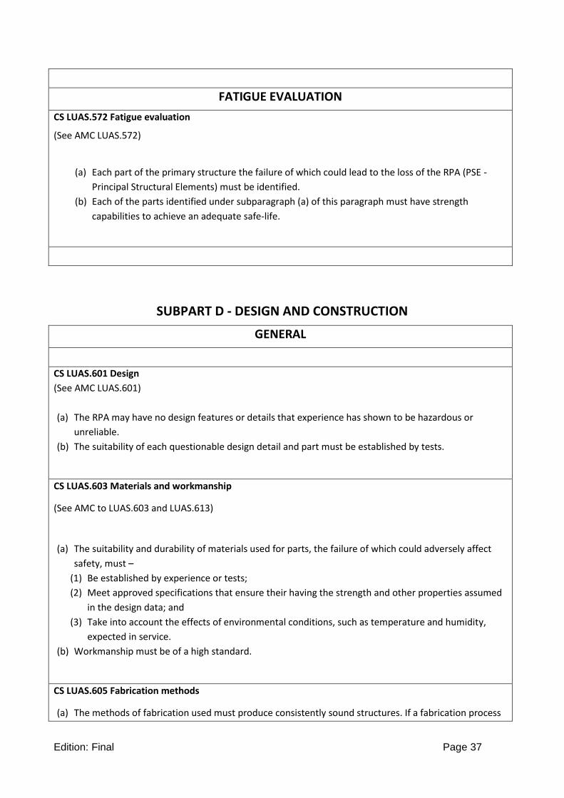
CS LUAS.572 Fatigue evaluation
(See AMC LUAS.572)
(a) Each part of the primary structure the failure of which could lead to the loss of the RPA (PSE -
Principal Structural Elements) must be identified.
(b) Each of the parts identified under subparagraph (a) of this paragraph must have strength
capabilities to achieve an adequate safe-life.
SUBPART D - DESIGN AND CONSTRUCTION
GENERAL
CS LUAS.601 Design
(See AMC LUAS.601)
(a) The RPA may have no design features or details that experience has shown to be hazardous or
unreliable.
(b) The suitability of each questionable design detail and part must be established by tests.
CS LUAS.603 Materials and workmanship
(See AMC to LUAS.603 and LUAS.613)
(a) The suitability and durability of materials used for parts, the failure of which could adversely affect
safety, must –
(1) Be established by experience or tests;
(2) Meet approved specifications that ensure their having the strength and other properties assumed
in the design data; and
(3) Take into account the effects of environmental conditions, such as temperature and humidity,
expected in service.
(b) Workmanship must be of a high standard.
CS LUAS.605 Fabrication methods
(a) The methods of fabrication used must produce consistently sound structures. If a fabrication process

Edition: Final Page 38
(such as gluing, spot welding, heat-treating, bonding, processing of composite materials) requires
close control to reach this objective, the process must be performed under an approved process
specification.
(b) Each new RPA fabrication method must be substantiated by a test program.
CS LUAS.607 Fasteners
(See AMC LUAS.607 (b))
(a) Each removable fastener must incorporate two retaining devices if the loss of such fastener would preclude continued safe flight and landing.
(b) Fasteners and their locking devices must not be adversely affected by the environmental conditions associated with the particular installation.
(c) No self-locking nut may be used on any bolt subject to rotation in operation unless a nonfriction locking device is used in addition to the self-locking device.
CS LUAS.609 Protection of structure
Each part of the structure must –
(a) Be suitably protected against deterioration or loss of strength in service due to any cause, including –
(1) Weathering;
(2) Corrosion; and
(3) Abrasion; and
(b) Have adequate provisions for ventilation and drainage.
CS LUAS.611 Accessibility
Means must be provided to allow inspection (including inspection of principal structural elements and control systems), close examination, repair, and replacement of each part requiring maintenance, adjustments for proper alignment and function, lubrication or servicing.
CS LUAS.613 Material strength properties and design values
(See AMC LUAS.603 and LUAS.613)
(a) Material strength properties must be based on enough tests of material meeting specifications to
establish design values on a statistical basis.
(b) The design values must be chosen to minimise the probability of structural failure due to material
variability. Except as provided in subparagraph (e), compliance with this paragraph must be shown by
selecting design values that assure material strength with the following probability:
(1) Where applied loads are eventually distributed through a single member within an assembly, the
failure of which would result in loss of structural integrity of the component; 99% probability
with 95% confidence.
(2) For redundant structure, in which the failure of individual elements would result in applied loads
being safely distributed to other load carrying members; 90% probability with 95% confidence.
(c) The effects of temperature on allowable stresses used for design in an essential component or
structure must be considered where thermal effects are significant under normal operating
conditions.

Edition: Final Page 39
(d) The design of structure must minimise the probability of catastrophic fatigue failure, particularly at
points of stress concentration.
(e) Design values greater than the guaranteed minimum’s required by this paragraph may be used where
only guaranteed minimum values are normally allowed if a “premium selection” of the material is
made in which a specimen of each individual item is tested before use to determine that the actual
strength properties of the particular item will equal or exceed those used in design.
CS-LUAS 619 Special factors
(See AMC LUAS.619)
The factor of safety prescribed in CS-LUAS.303 must be multiplied by the highest pertinent special factors of safety prescribed in CS-LUAS.621 to 625 for each part of the structure whose strength is –
(a) Uncertain; (b) Likely to deteriorate in service before normal replacement; or (c) Subject to appreciable variability because of uncertainties in manufacturing processes or inspection
methods for composite structures, a special test factor which takes into account material variability and the effects of temperature and absorption of moisture must be used.
CS-LUAS.621 Casting factors
For castings, the strength of which is substantiated by at least one static test and which are inspected by visual methods, a casting factor of 2·0 must be applied. This factor may be reduced to 1·25 providing the reduction is substantiated by tests on not less than three sample castings and all production castings are subjected to an approved visual and radiographic inspection or an a proved equivalent non-destructive inspection method.
CS-LUAS.623 Bearing factors
(a) Each part that has clearance (free fit), and that is subject to pounding or vibration, must have a bearing factor large enough to provide for the effects of normal relative motion.
(b) For control surface hinges and control system joints, compliance with the factors prescribed in CS-LUAS.657 and 693, respectively, meets sub-paragraph (a) of this paragraph.
CS- LUAS.625 Fitting factors
For each fitting (a part or terminal used to joint one structural member to another), the following apply:
(a) For each fitting whose strength is not proven by limit and ultimate load tests in which actual stress conditions are simulated in the fitting and surrounding structures, a fitting factor of at least 1·15 must be applied to each part of –
(1) The fitting; (2) The means of attachment; and (3) The bearing on the joined members.
(b) No fitting factor need be used for joint designs based on comprehensive test data (such as continuous joints in metal plating, welded joints, and scarf joints in wood).
(c) For each integral fitting, the part must be treated as a fitting up to the point at which the section properties become typical of the member.

Edition: Final Page 40
CS-LUAS.627 Fatigue strength
The structure must be designed, as far as practicable, to avoid points of stress concentration where variable stresses above the fatigue limit are likely to occur in normal service.
CS 23.629 Flutter
(See AMC LUAS.629(a) )
(a) It must be shown by the methods of (b) or (c), that the RPA is free from flutter, control reversal and
divergence for any condition of operation within the limit V-n envelope and at all speeds up to the
speed specified for the selected method. In addition –
(1) Adequate tolerances must be established for quantities which affect flutter; including speed,
damping, mass balance and control system stiffness; and
(2) The natural frequencies of main structural components must be determined by vibration tests or
other approved methods.
(b) Flight flutter tests must be made to show that the RPA is free from flutter, control reversal and
divergence and to show by these tests that –
(1) Proper and adequate attempts to induce flutter have been made within the speed range up to VD;
(2) The vibratory response of the structure during the test indicates freedom from flutter;
(3) A proper margin of damping exists at VD; and
(4) There is no large and rapid reduction in damping as VD is approached.
(c) Any rational analysis used to predict freedom from flutter, control reversal and divergence must cover
all speeds up to 1·2 VD.
(e) For turbo-propeller powered RPA, the dynamic evaluation must include –
(1) Whirl mode degree of freedom which takes into account the stability of the plane of rotation of
the propeller and significant elastic, inertial and aerodynamic forces; and
(2) Propeller, engine, engine mount and RPA structure stiffness and damping variations appropriate to
the particular configuration.
(f) Freedom from flutter, control reversal and divergence up to VD/MD must be shown after the failure,
malfunction, or disconnection of any single element in the primary flight control system, any tab
control system, or any flutter damper.
(g) For failure conditions in those systems covered by CS LUAS.302, the margins defined in Appendix C
apply.
WINGS
CS LUAS.641 Proof of strength
The strength of stressed-skin wings must be proven by load tests or by combined structural analysis and load tests.

Edition: Final Page 41
CONTROL SURFACES
CS LUAS.651 Proof of strength
(a) Limit load tests of control surfaces are required. These tests must include the horn or fitting to
which the control system is attached.
(b) In structural analyses, rigging loads due to wire bracing must be accounted for in a rational or
conservative manner.
CS LUAS.655 Installation
(a) Movable surfaces must be installed so that there is no interference between any surfaces, their bracing or adjacent fixed structure, when one surface is held in its most critical clearance positions and the others are operated through their full movement.
(b) If an adjustable stabiliser is used, it must have stops that will limit its range of travel to that allowing safe flight and landing.
CS-LUAS.657 Hinges
(a) Control surface hinges, except ball and roller bearing hinges, must have a factor of safety of not less than 6·67 with respect to the ultimate bearing strength of the softest material used as a bearing.
(b) For ball or roller bearing hinges, the approved rating of the bearing may not be exceeded. (c) Hinges must have enough strength and rigidity for loads parallel to the hinge line.
CS LUAS.659 Mass balance
The supporting structure and the attachment of concentrated mass balance weights used on control
surfaces must be designed for limit loads within the design envelope, considering an appropriate safety
factor as agreed with the Authority. Corresponding to the following directions
(a) normal to the plane of the control surface;
(b) fore and aft; and
(c) parallel to the hinge line.
CS-LUAS.671 General
(See AMC CS LUAS.671)
(a) Each control must operate smoothly and positively enough to allow proper performance of its
functions.
(b) Each element of each RPA flight control system must be designed, or distinctively and permanently
marked, to prevent any incorrect assembly that could result in the malfunction of the system.

Edition: Final Page 42
CS-LUAS.673 Primary flight controls
Primary flight controls are those used for the immediate control of pitch, roll and yaw. They consist of the RPA systems according to CS-LUAS.1329 and the RPS systems according to CS-LUAS.1729
CS LUAS.675 Stops
(a) Each control system must have stops that positively limit the range of motion of each movable
aerodynamic surface controlled by the system.
(b) Each stop must be located so that wear, slackness, or take-up adjustments will not adversely affect
the control characteristics of the RPA because of a change in the range of surface travel.
(c) Each stop must be able to withstand any loads co responding to the design conditions for the control
system.
CS-LUAS.677 Trim systems
If a trimming system is installed the following must be applied:
(a) Reserved
(b) Trimming devices must be designed so that, when any one connecting or transmitting element in the
primary flight control system fails, adequate control for safe flight and landing or for emergency
recovery according to CS LUAS.1412 is available
(c) Tab controls must be irreversible unless the tab is properly balanced and has no unsafe flutter
characteristics. Irreversible tab systems must have adequate rigidity and reliability in the portion of
the system from the tab to the attachment of the irreversible unit to the aeroplane structure.
(d) The Flight Control System (FCS) must trim the RPA in such a manner that a maximum of control
remains and that dynamic characteristics and safety margins are not compromised.
(e) It must be demonstrated that the aeroplane is safely controllable and that the pilot can perform all
the manoeuvres and operations necessary to effect a safe landing following any probable powered
trim system runaway that reasonably might be expected in service, allowing for appropriate time
delay after pilot recognition of the trim system runaway. The demonstration must be conducted at
the critical aeroplane weights and centre of gravity positions.
CS-LUAS.679 Control system locks
If there is a device to lock the flight controls (a) There must be a means to warn the ground staff when the device is engaged; (b) There must be a means to warn the RPA Pilot when the device is engaged. (c) The device must have a means to preclude the possibility of it becoming inadvertently engaged in
flight.
CS LUAS.681 Limit load static tests
(a) Compliance with the limit load requirements must be shown by tests in which –
(1) The direction of the test loads produces the most severe loading in the control system; and
(2) Each fitting, pulley and bracket used in attaching the system to the main structure is included.
(b) Compliance must be shown (by analyses or individal load tests) with the special factor requirements
for control system joints subject to angular motion.

Edition: Final Page 43
CS-LUAS.683 Operation tests
(See AMC 23.683)
(a) It must be shown by operation tests that, when the controls are operated from the RPA Pilot with the
system loaded as prescribed in sub-paragraph (b) , the system is free from –
(1) Jamming;
(2) Excessive friction;
(3) Excessive deflection.
(b) The prescribed test loads are –
(1) For the entire system, loads corresponding to the limit air loads on the appropriate surface, or the
limit pilot forces in CSLUAS.397 (b), whichever are less; and
(2) For secondary controls, loads not less than those corresponding to the maximum pilot effort
established under CS-LUAS.405.
CS-LUAS.685 Control system details
(a) Each detail of each control system must be designed and installed to prevent jamming, chafing and
interference from cargo, ground crew, loose objects, or the freezing of moisture.
(b) There must be means to prevent the slapping of cables or tubes against other parts.
(c) Each element of the flight control system must have design features, or must be distinctively and
permanently marked, to minimise the possibility of incorrect assembly that could result in
malfunctioning of the control system.
CS-LUAS.687 Spring devices
The reliability of any spring device used in the control system must be established by tests simulating service conditions unless failure of the spring will not cause flutter or unsafe flight characteristics.
CS-LUAS.689 Cable systems
If cables are used to operate the flight controls, the following applies. (a) Each cable, cable fitting, turn-buckle, splice and pulley used must meet standard specifications. In
addition –
(1) Each cable used in primary control systems must comply with CS LUAS.681;
(2) Each cable system must be designed so that there will be no hazardous change in cable tension
throughout the range of travel under operating conditions and temperature variations; and
(3) There must be means for visual inspection at each fairlead, pulley, terminal and turnbuckle.
(b) Each kind and size of pulley must correspond to the cable with which it is used. Each pulley must have
closely fitted guards to prevent the cables from being misplaced or fouled, even when slack. Each
pulley must lie in the plane passing through the cable so that the cable does not rub against the pulley
flange.
(c) Fairleads must be installed so that they do not overstress the cable in a change of direction, in order
to prevent fatigue failure or excessive wear.
(d) Clevis pins subject to load or motion and retained only by cotter pins may not be used in the control
system.
(e) Turnbuckles must be attached to parts having angular motion in a manner that will positively prevent
binding throughout the range of travel.

Edition: Final Page 44
CS LUAS.693 Joints
Control system joints (in push-pull systems) that are subject to angular motion, except those in ball and roller bearing systems, must have a special factor of safety of not less than 3·33 with respect to the ultimate bearing strength of the softest material used as a bearing. This factor may be reduced to 2·0 for joints in cable control systems. For ball or roller bearings, the approved ratings may not be exceeded.
CS-LUAS.697 Wing flap controls
(a) Each wing flap control must be designed so that, when the flap has been placed in any position upon
which compliance with the performance requirements of CS-LUAS is based, the flap will not move
from that position unless the control is adjusted or is moved by the automatic operation of a flap load
limiting device.
(b) The rate of movement of the flaps in response to the commanded position must give satisfactory
flight and performance characteristics under steady or changing conditions of airspeed, engine power
and attitude.
CS LUAS.701 Flap interconnection
(AMC LUAS.701)
The RPA must be shown to have safe flight characteristics and structural integrity with any combination of extreme positions of individual movable surfaces not shown to be extremaly improbable (mechanically interconnected surfaces are to be considered as a single surface).
LANDING GEAR
CS LUAS.722 General
(See AMC LUAS.722 )
(a) Landing system includes landing gears, skis, skids, parachute system and other special landing devices.
(b) The landing system must be designed to prevent in normal operations any damage to the structure
and systems of the RPA that could result in a subsequent catastrophic condition or reduce the
required reliability of the RPA.
(c) Compliance with the CS LUAS.471 to LUAS.545and CS LUAS.722(b) must be demonstrated by a
method agreed with the Authority. For conventional landing gear arrangements, the methods of
Appendix H can be applied.
(d) In showing compliance with subparagraph (b) adequate safety margins must be assured over the
normal operating conditions.
FLOATS
CS LUAS.753 Float design
Each sea- or amphibian RPA float must meet the requirements of CS LUAS.545.

Edition: Final Page 45
FIRE PROTECTION
CS-LUAS.855 Cargo compartments
(a) Each cargo compartment must be constructed of, or lined with, materials that are at least Fire
Resistant.
(b) No compartment may contain any controls, wiring, lines, equipment, or accessories whose damage or
failure would affect the Emergency Recovery Capability according CS-LUAS.1412, unless those items
are protected so that-
(c) They cannot be damaged by the movement of cargo in the compartment; and
(d) Their breakage or failure will not create a fire hazard.
CS-LUAS.859 Temperature control systems
(a) General. Any temperature control system required by the flight control and other critical systems
must be able to maintain the temperatures of those critical systems within the limits established for
those systems under critical operating conditions.
(b) Any temperature control systems required by the flight control or other critical systems must not fail
in such a way that will interfere with the function of those critical systems.
CS-LUAS.861 Fire protection of flight controls, flight structure and essential parts
(AMC-LUAS.861)
Each part of the structure, Flight controls, engine mounts, and other parts essential for an Emergency Recovery according to CS-LUAS.1412 that would be affected by powerplant fires must be protected so they can perform their essential functions for not less than the time required to perform the emergency recovery according CS-LUAS.1412 under any foreseeable powerplant fire conditions.
CS-LUAS.863 Flammable fluid fire protection
In each area where flammable fluids or vapours might escape by leakage of a fluid system, there must be means in the form of adequate segregation, ventilation and drainage, to minimize the probability of ignition of the fluids and vapours, and the resultant hazards if ignition does occur
ELECTRICAL BONDING AND LIGHTNING PROTECTION
CS-LUAS.867 Electrical bonding and protection against lightning and static electricity
(See AMC CS-LUAS.867)
(a) The RPAS must be protected against Catastrophic effects from lightning and static electricity. A lightning analysis assessment has to be carried out and agreed with the Certifying Authority.
(b) For metallic components, compliance with sub-paragraph (a) may be shown by (1) Bonding the components and grounding them properly to the airframe; or (2) Designing the components so that a strike will not result in a Catastrophic event.
(c) For non-metallic components, compliance with sub-paragraph (a) may be shown by (1) Designing the components to minimize the effect of a strike; or (2) Incorporating acceptable means of diverting the resulting electrical current so as not to result in a
Catastrophic event (d) There must be provisions for electrically bonding the RPAS to the ground fuelling equipment

Edition: Final Page 46
SUBPART E - POWERPLANT
GENERAL
CS LUAS.901 Installation
(a) The powerplant installation includes each component that – (1) Is necessary for propulsion; and (2) Affects the safety of the major propulsive units.
(b) Each powerplant installation must be constructed and arranged to – (1) Ensure safe operation to the maximum altitude for which approval is requested. (2) Be accessible for necessary inspections and maintenance.
(c) Engine cowls and nacelles must be easily removable or openable by the pilot to provide adequate access to and exposure of the engine compartment for pre-flight checks.
(d) Each turbine engine installation must be constructed and arranged to – (1) Result in carcass vibration characteristics that do not exceed those established during the
type certification of the engine. (2) Ensure that the capability of the installed engine to withstand the ingestion of rain, hail,
ice, and birds into the engine inlet is not less than the capability established for the engine.
(e) The powerplant installation must comply with – (1) The installation instructions provided under –
i. The engine type certificate or Appendix B, and ii. The propeller type certificate or Appendix B.
(2) The applicable provisions of this subpart. (f) Each auxiliary power unit installation must meet the applicable portions of CS-LUAS.
CS LUAS.903 Engines and auxiliary power units
(a) Engine Type Certificate (1) Each engine must have a Type Certificate or to be approved as part of RPA certification in
accordance with Appendix B. (b) Turbine engine installations. For turbine engine installations –
(1) Design precautions must be taken to minimise the hazards to the RPA in the event of an engine rotor failure or of a fire originating inside the engine which burns through the engine case. (See AMC 20-128A)
(2) The powerplant systems associated with engine control devices, systems and instrumentation must be designed to give reasonable assurance that those operating limitations that adversely affect turbine rotor structural integrity will not be exceeded in service.
(c) Engine isolation. In multiple-engine applications, the powerplants must be arranged and isolated from each other to allow operation, in at least one configuration, so that the failure or malfunction of any engine, or the failure or malfunction (including destruction by fire in the engine compartment) of any system that can affect an engine will not
(1) Prevent the continued safe operation of the remaining engines; or (2) Require immediate action by any RPA crew for continued safe operation of the remaining
engine. (d) Starting and stopping
(1) Any techniques and associated limitations for engine starting and stopping must be established and included in the RPAS Flight Manual and in the RPAS Maintenance Manual.
(2) For safety purpose, there must be a means to prevent inadvertent engine starting on the ground.
(3) The design of the installation must be such that risk of fire or mechanical damage to the

Edition: Final Page 47
engine or RPA, as a result of starting the engine in any conditions in which starting is to be permitted, is reduced to a minimum.
(4) There must be means for stopping any engine in flight or combustion for turbine engine, after engine failure, if continued engine rotation would cause a hazard to the RPA.
(e) Restart capability (1) Engine restart capability and demonstration should be weighed with the risk of engine
loss and corresponding emergency procedures as defined in CS LUAS.1413 (c) and related operational limitations.
(2) Where restart capability is required, i. Any techniques and associated limitations must be established and included in
the RPA System Flight Manual, or applicable operating placards. ii. It must be demonstrated in flight that when restarting engines following a false
start, all fuel or vapor is discharged in such a way that it does not constitute a fire hazard.
iii. Restart envelope. An altitude and airspeed envelope must be established for the RPA for in-flight engine restarting.
iv. For turbine engine-powered RPA, if the minimum windmilling speed of the engines, following the in-flight shutdown of all engines, is insufficient to provide the necessary electrical power for engine ignition, a power source independent of the engine-driven electrical power generating system must be provided to permit in-flight engine ignition for restarting.
(f) Auxiliary power units. Each APU must be ETSO approved or to be approved as part of RPA certification in accordance with Appendix B.
CS LUAS.905 Propellers
(a) Each propeller must have a Type Certificate or approved as part of RPA certification in accordance with Appendix B.
(b) Engine power and propeller shaft rotational speed may not exceed the limits for which the propeller is certificated or approved.
(c) Each featherable propeller must have a means to unfeather it in flight. (d) Each propeller blade pitch control system must meet the following:
i. No single failure or malfunction in the Propeller will result in unwanted travel of the Propeller blades to a position below the In-Flight Low-Pitch Position.
ii. Structural elements, the failure of which could prevent the RPA to continue in safe, controlled flight and landing, must comply with structural and fatigue evaluation requirements of CS LUAS.
iii. The extent of any intended travel below the normal In-Flight Low-Pitch Position must be documented in the appropriate manuals.
(e) All areas of the RPA forward of the pusher propeller that are likely to accumulate and shed ice into the propeller disc during any operating condition must be suitably protected to prevent ice formation, or it must be shown that any ice shed into the propeller disc will not create a hazardous condition. (See AMC LUAS.905 (e)).
(f) Each pusher propeller must be marked so that the disc is conspicuous under normal daylight ground conditions.
(g) If the engine exhaust gases are discharged into the pusher propeller disc, it must be shown by tests, or analysis supported by tests, that the propeller is capable of continuous safe operation. (See AMC LUAS.905 (g)).
(h) All engine cowlings, access doors, and other removable items must be designed to ensure that they will not separate from the RPA and contact the pusher propeller.
CS LUAS.907 Propeller vibration
(See AMC LUAS.907)

Edition: Final Page 48
(a) Each propeller other than a conventional fixed pitch wooden propeller must be shown to have vibration stresses, in normal operating conditions, that do not exceed values that have been shown by the propeller manufacturer to be safe for continuous operation. This must be shown by –
(1) Measurement of stresses through direct testing of the propeller; (2) Comparison with similar installations for which these measurements have been made; or (3) Any other acceptable test method or service experience that proves the safety of the
installation. (b) Proof of safe vibration characteristics for any type of propeller, except for conventional, fixed-
pitch, wood propellers must be shown where necessary.
CS LUAS.909 Turbo charger systems
(See AMC 23.909 (d) (1))
(a) Each turbo charger must be approved under the engine type certificate or it must be shown that the turbo charger system, while in its normal engine installation and operating in the engine environment –
(1) Can withstand, without defect, an endurance test for a time period that has been used in the engine certification or in accordance with Appendix B, and
(2) Will have no adverse effect upon the engine. (b) Control system malfunctions, vibrations and abnormal speeds and temperatures expected in
service may not damage the turbo charger compressor or turbine. (c) Each turbo charger case must be able to contain fragments of a compressor or turbine that fails at
the highest speed that is obtainable with normal speed control devices in-operative. (d) Each intercooler installation, where provided, must comply with the following:
(1) The mounting provisions of the intercooler must be designed to withstand the loads imposed on the system;
(2) It must be shown that, under the installed vibration environment, the intercooler will not fail in a manner allowing portions of the intercooler to be ingested by the engine, and
(3) Airflow through the intercooler must not discharge directly on any RPA component unless such discharge is shown to cause no hazard to the RPA under all operating conditions.
(e) Engine power, cooling characteristics, operating limits, and procedures affected by the turbocharger system installations must be evaluated. Turbocharger operating procedures and limitations must be included in the flight manual.
CS LUAS.925 Propeller clearance
For safe operation of each RPA, propeller clearances with the RPA at the most adverse combination of weight and centre of gravity (RPA structural deformation must be take in consideration) and with the propeller in the most adverse pitch position, may not be less than the following:
(a) Ground clearance. There must be an enough safe clearance between each propeller and the ground with the landing gear statically deflected and in the level, normal take-off, or taxiing attitude, whichever is the most critical. In addition, for each RPA with conventional landing gear struts using fluid or mechanical means for absorbing landing shocks, there must be positive clearance between the propeller and the ground in the level take-off attitude with the critical tyre completely deflated and the corresponding landing gear strut bottomed. Positive clearance for RPA using leaf spring struts is shown with a deflection corresponding to 1·5g.
(b) Aft mounted propellers. In addition to the clearance specified in sub-paragraph (a) an RPA with an aft mounted propeller must be designed such that the propeller will not contact the runway surface when the RPA is in the maximum pitch attitude attainable during normal take-off and landings.
(c) Water clearance. There must be an enough safe clearance between each propeller and the water in the most adverse condition during take-off and landing in the water.
(d) Rocket assisted take-off or catapult assisted take-off RPA. There must be enough safe clearance

Edition: Final Page 49
between the propeller and the launch system (catapult, launching ramp, …). This clearance must be kept during all the launching phase.
(e) Reserved. (f) Structural clearance. In the most adverse conditions, there must be:
(1) enough safe radial clearance between the blade tips and the RPA structure, plus any additional radial Clearance necessary to prevent harmful vibration;
(2) enough safe longitudinal clearance between the propeller blades or cuffs and stationary parts of the RPA; and
(3) positive clearance between other rotating parts of the propeller or spinner and stationary parts of the RPA.
CS LUAS.939 Powerplant operating characteristics
(See AMC LUAS.939)
(a) Turbine engine powerplant operating characteristics must be investigated in flight to determine that no adverse characteristics (such as stall, surge, or flameout) are present, to a hazardous degree, during normal and emergency operations within the range of operating limitations of the RPA and of the engine.
(b) Turbocharged reciprocating engine operating characteristics must be investigated in flight to assure that no adverse characteristics, as a result of an inadvertent overboost, surge, flooding, or vapour lock, are present during normal or emergency operation of the engine(s) throughout the range of operating limitations of both RPA and engine.
(c) For turbine engines, the air inlet system must not, as a result of airflow distortion during normal operation, cause vibration harmful to the engine.
CS LUAS.943 Negative acceleration
(AMC LUAS.943)
No hazardous malfunction of an engine, an auxiliary power unit approved for use in flight, or any component or system associated with the powerplant or auxiliary power unit may occur when the RPA is operated at the negative accelerations within the flight envelopes
prescribed in CS LUAS.333. This must be shown for the greatest value and duration of the acceleration expected in service.
LIQUID FUEL SYSTEM
CS LUAS.951 General
(AMC LUAS.951(a))
(a) Each fuel system must be constructed and arranged to ensure fuel flow at a rate and pressure established for proper engine and auxiliary power unit functioning under each likely operating condition, including any manoeuvre for which certification is requested and during which the engine or auxiliary power unit is permitted to be in operation.
(b) Each fuel system must be arranged so that (1) No fuel pump can draw fuel from more than one tank at a time; or (2) There are means to prevent introducing air into the system.
(c) Each fuel system for a turbine engine must be capable of sustained operation throughout its flow and pressure range with fuel initially saturated with water at 27°C (80°F) and having 0.75cc of free water per 3.8 l (US-gallon) added and cooled to the most critical condition for icing likely to be encountered in operation.

Edition: Final Page 50
CS LUAS.955 Fuel flow
(a) General. The ability of the fuel system to provide fuel at the rates specified in this paragraph and at a pressure sufficient for proper carburettor operation must be shown in the attitude that is most critical with respect to fuel feed and quantity of unusable fuel. These conditions may be simulated in a suitable mockup. In addition -
(1) The quantity of fuel in the tank may not exceed the amount established as the unusable fuel supply for that tank under CS LUAS.959 plus that necessary to show compliance with this paragraph; and
(2) If there is a fuel flowmeter, it must be blocked during the flow test and the fuel must flow through the meter bypass.
(b) Gravity systems. The fuel flow rate for gravity systems (main and reserve supply) must be 150% of the take-off fuel consumption of the engine.
(c) Pump systems. The fuel flow rate for each pump system (main and reserve supply) must be 125% of the take-off fuel consumption of the engine(s) it supports, at the maximum power established for take-off. This flow rate is required for each main pump and each emergency pump, and must be available when the pump is running as it would during take-off.
(d) Multiple fuel tanks. If the engine can be supplied with fuel from more than one tank, it must be possible, in level flight, to regain full power and fuel pressure to that engine in not more than 10 seconds after switching to any full tank after engine malfunctioning due to fuel depletion becomes apparent while the engine is being supplied from any other tank.
(e) Turbine engine fuel systems. Each turbine engine fuel system must provide at least 100% of the fuel flow required by the engine under each intended operation condition and manoeuvre. The conditions may be simulated in a suitable mockup. This flow must –
(1) Be shown with the RPA in the most adverse fuel feed condition (with respect to altitudes, attitudes and other conditions) that is expected in operation; and
(2) Reserved
(3) For single engine RPAs, require no pilot action after completion of the engine starting phase of operations unless means are provided that unmistakenly alert the pilot to take any needed action at least five minutes prior to the needed action; such pilot action must not cause any change in engine operation; and such pilot action must not distract pilot attention from essential flight duties during any phase of operations for which the RPA is approved.
CS LUAS.957 Flow between interconnected tanks
(a) It must be impossible, in a gravity feed system with interconnected tank outlets, for enough fuel to
flow between the tanks to cause an overflow of fuel from any tank vent under the conditions in CS
LUAS.959, except that full tanks must be used.
(b) If fuel can be pumped from one tank to another in flight, the fuel tank vents and the fuel transfer
system must be designed so that no structural damage to any airplane component can occur because
of overfilling of any tank
CS LUAS.959 Unusable fuel supply
(See AMC 23.959 (a))
(a) The unusable fuel supply for each tank must be established as not less than that quantity at which the first evidence of malfunctioning occurs under the most adverse fuel feed condition occurring under each intended operation and flight manoeuvre involving that tank. Fuel system component failures need not be considered.
(b) In addition, the effect on the unusable fuel quantity as a result of a failure of any pump must be determined.

Edition: Final Page 51
CS LUAS.961 Fuel system hot weather operation
(See AMC 23.961)
Each fuel system must be free from vapor lock when using the most critical fuel for which certification is requested, heated to its critical temperature, with respect to vapor formation, when operating the RPA in all critical operating and environmental conditions.
CS LUAS.963 Fuel tanks: general
(a) Each fuel tank must be able to withstand, without failure, the vibration, inertia, fluid, and structural loads that it may be subjected to in operation.
(b) Each flexible fuel tank liner must be of an acceptable kind. (c) Each integral fuel tank must have adequate facilities for interior inspection and repair.
CS LUAS.965 Fuel tank tests
(AMC LUAS.965(d))
Each fuel tank must be able to withstand the following pressures without failure or leakage:
(a) For each conventional metal tank and non-metallic tank with walls not supported by the RPA structure, a pressure of 24 kPa or that pressure developed during maximum ultimate acceleration with a full tank, whichever is greater.
(b) For each integral tank, the pressure developed during the maximum limit acceleration of the RPA with a full tank, with simultaneous application of the critical limit structural loads.
(c) For each non-metallic tank with walls supported by the RPA structure and constructed in an acceptable manner using acceptable basic tank material, and with actual or simulated support conditions, a pressure of 14 kPa, for the first tank of a specific design. The supporting structure must be designed for the critical loads occurring in the flight or landing strength conditions combined with the fuel pressure loads resulting from the corresponding accelerations.
(d) For pressurized fuel tank like a bottle, a proof and burst tests must be performed. A proof factor of 1.5 and a burst factor of 2.0 must be applied to maximum working pressure. Proof pressure should be held for a minimum of 2 minutes and should not cause any leakage or permanent distortion. Burst pressure should be held for a minimum of 1 minute and should not cause rupture but some distortion is allowed. The supporting structure must be designed for the critical loads occurring in the flight or landing strength conditions.
CS LUAS.967 Fuel tank installation
(a) Each fuel tank must be supported so that tank loads are not concentrated. In addition ·– (1) There must be pads, if necessary, to prevent chafing between each tank and its supports; (2) Padding must be non-absorbent or treated to prevent the absorption of fuel; (3) If flexible tank liner is used, it must be supported so that it is not required to withstand fluid loads; (4) Interior surfaces adjacent to the liner must be smooth and free from projections that could cause
wear, unless – (i) Provisions are made for protection of the liner at those points; or (ii) The construction of the liner itself provides such protection;
(5) A positive pressure must be maintained within the vapour space of each bladder cell under all conditions of operation except for a particular condition for which it is shown that a zero or negative pressure will not cause the bladder cell to collapse; and
(6) Siphoning of fuel (other than minor spillage) or collapse of bladder fuel cells may not result from improper securing or loss of the fuel filler cap.
(b) Each tank compartment must be ventilated and drained to prevent the accumulation of flammable fluids or vapours. Each compartment adjacent to a tank that is an integral part of the RPA structure must also be ventilated and drained.
(c) No fuel tank may be on the engine side of the firewall. There must be at least 13 mm of clearance

Edition: Final Page 52
between the fuel tank and the firewall. No part of the engine nacelle skin that lies immediately behind a major air opening from the engine compartment may act as the wall of an integral tank.
(d) Reserved. (e) Fuel tanks and fuel system components must be designed, located, and installed so as to retain fuel -
(1) Under the inertia forces prescribed for the emergency landing conditions in CS LUAS.561; and (2) Under conditions likely to occur when an RPA lands on a paved runway at a normal landing speed
under each of the following conditions: (i) The RPA in a normal landing attitude and its landing gear retracted. (ii) The most critical landing gear leg collapsed and the other landing gear legs extended.
CS LUAS.969 Fuel tank expansion space
Each fuel tank, other than pressurized fuel tank, must have an expansion space of not less than 2% of the tank capacity, unless the tank vent discharges clear of the RPA (in which case no expansion space is required). It must be impossible to fill the expansion space inadvertently with the RPA in the normal ground attitude.
CS-LUAS 971 Fuel tank sump
(a) Each fuel tank, other than pressurized fuel tank, must have a sump with an effective capacity, in the normal ground and flight attitudes, of 0.10% of the tank capacity, unless –
(1) The fuel system has a sufficient capacity sediment bowl or chamber that is accessible for drainage, and.
(2) Each fuel tank outlet is located so that in the normal ground attitude, water will drain from all parts of the tank to the sediment bowl or chamber.
(b) Each sump, sediment bowl, and sediment chamber drain required by subparagraph (a) of this paragraph must comply with the drain provisions of CS LUAS.999 (b)(1), (2) and (3).
CS LUAS.973 Fuel tank filler connection
(a) Each fuel tank filler connection must be marked as prescribed in CS LUAS.1557 (b). (b) Spilled fuel must be prevented from entering the fuel tank compartment or any part of the RPA
other than the tank itself. (c) Each filler cap must provide a fuel-tight seal for the main filler opening. However, there may be
small openings in the fuel tank cap for venting purposes or for the purpose of allowing passage of a fuel gauge through the cap provided such openings comply with the requirements of CS LUAS.975 (a).
(d) Each fuel filling point, except pressure fueling connection points, must have a provision for electrically bonding the RPA to ground fueling equipment.
CS LUAS.975 Fuel tank vents and carburettor vapour vents
(a) Each fuel tank must be vented from the top part of the expansion space. In addition – (1) Each vent outlet must be located and constructed in a manner that minimizes the
possibility of its being obstructed by ice or other foreign matter; (2) Each vent must be constructed to prevent siphoning of fuel during normal operation; (3) The venting capacity must allow the rapid relief of excessive differences of pressure
between the interior and exterior of the tank; (4) Airspaces of tanks with interconnected outlets must be interconnected; (5) There may be no undrainable points in any vent line where moisture can accumulate with
the RPA in either the ground or level flight attitudes; (6) No vent may terminate at a point where the discharge of fuel from the vent outlet will
constitute a fire hazard; and (7) Vents must be arranged to prevent the loss of fuel, except fuel discharged because of
thermal expansion, when the RPA is parked in any direction on a ramp having a 1% slope. (b) Each carburettor with vapour elimination connections and each fuel injection engine employing

Edition: Final Page 53
vapour return provisions must have a separate vent line to lead vapours back to the top of one of the fuel tanks. If there is more than one tank and it is necessary to use these tanks in a definite sequence for any reason, the vapour vent line must lead back to the fuel tank to be used first, unless the relative capacities of the tanks are such that return to another tank is preferable.
CS LUAS.977 Fuel tank outlet
(a) There must be a fuel strainer for the fuel tank outlet or for the booster pump to prevent the passage of any object that could restrict fuel flow or damage any fuel system component
(b) The clear area of each fuel tank outlet strainer must be at least five times the area of the outlet line.
(c) The diameter of each strainer must be at least that of the fuel tank outlet. (d) Each strainer must be accessible for inspection and cleaning.
ELECTRICAL POWER SUBSYSTEM FOR PROPULSION
CS-LUAS.981 Energy Storage, Performance and Indication
(a) The battery must be able to provide the necessary voltage and current required by the engine and electrical equipment throughout the complete operational envelope.
(b) The battery pack charger must be considered part of the RPAS. The charger must have indicators for fault and charging status.
CS-LUAS.983 Energy Storage, Safety
(a) Safe cell temperatures and pressures must be maintained during any probable charging or discharging condition, or during any failure of the charging or battery monitoring system not shown to be extremely remote. The battery installation must be designed to preclude Hazardous effect due to explosion in the event of those failures..
(b) Design of the batteries must consider the occurrence of self-sustaining, uncontrolled increases in temperature or pressure. Associated protection means shall be implemented as per (a).
(c) No explosive or toxic gasses emitted by any battery in normal operation or as the result of any failure of the battery charging or monitoring system, or battery installation not shown to be extremely remote, may accumulate in hazardous quantities within the aircraft.
(d) Battery installations must meet the requirements of CS LUAS.863
(e) No corrosive fluids or gasses that may escape from any battery may damage surrounding structure or any adjacent systems, equipment or electrical wiring, of the airplane in such a way as to cause a failure condition that is not compliant with CS LUAS.1309 (b).
(f) Each battery installation must have provisions to prevent any hazardous effect on structure or essential systems that may be caused by the maximum amount of heat the battery can generate during a short circuit of the battery or of its individual cells.
(g) Battery control and monitoring system must have an automatic function to control the charging rate of the battery so as to prevent battery overheating or overcharging, and,
(1) A battery temperature sensing and over-temperature warning system with a means for automatically disconnecting the battery from its charging source in the event of an over-temperature condition or,
(2) A battery failure sensing and warning system with a means for automatically disconnecting the battery from its charging source in the event of battery failure.

Edition: Final Page 54
(h) Any battery installation whose function is required for safe operation of the aircraft, must incorporate a monitoring and warning feature that will provide an indication to the appropriate flight crewmembers, whenever the state of charge (SOC) of the batteries have fallen below levels considered acceptable for dispatch of the aircraft.
(i) The Instructions for Continued Airworthiness required by CS LUAS.1529 must contain maintenance requirements for measurements of battery capacity at appropriate intervals to ensure that batteries whose function is required for safe operation of the aircraft will perform their intended function as long as the batteries are installed in the aircraft. The Instructions for Continued Airworthiness must also contain maintenance procedures for batteries in spares storage to prevent the replacement of batteries whose function is required for safe operation of the aircraft, with batteries that have experienced degraded charge retention ability or other damage due to prolonged storage at low SOC
CS-LUAS.985 Energy Storage, Installation
(a) The battery installation must be able to withstand the applicable inertial and vibration loads. (b) The installation provisions, the environment and the intended usage of all batteries must meet all
performance, operating and safety requirements established by the battery manufacturer. (c) There must be means to minimize the risk of battery overheating/explosion (e.g. cooling, temperature
sensor, active battery management system). (d) Information concerning battery storage, operation, handling, maintenance, safety limitations and
battery health conditions must be provided in the applicable manuals per subpart G.
LIQUID FUEL SYSTEM COMPONENTS
CS LUAS.991 Fuel pumps
(AMC LUAS.991(e))
For engine installations having fuel pumps to supply fuel to the engine, in addition to the main pump(s) the following is required:
(a) One emergency pump immediately available to supply fuel to the engine if any main pump (other than a fuel injection pump approved as part of an engine) fails.
(b) The power supply for each emergency pump must be independent of the power supply for each main pump.
(c) For each main pump, provision must be made to allow the by-pass of each positive displacement fuel pump other than a fuel injection pump approved as part of the engine
(d) If both the main pump and emergency pump operate continuously, there must be a means to indicate to the appropriate RPA crew members a malfunction of either pump.
(e) Operation of any fuel pump may not affect engine operation so as to create a hazard, regardless of the engine power or thrust setting or the functional status of any other fuel pump
CS LUAS.993 Fuel system lines and fittings
(AMC LUAS.993(e))
(a) Each fuel line must be installed and supported to prevent excessive vibration and to withstand loads due to fuel pressure and accelerated flight conditions.
(b) Each fuel line connected to components of the aeroplane between which relative motion could exist must have provisions for flexibility.
(c) Each flexible connection in fuel lines that may be under pressure and subjected to axial loading must use flexible hose assemblies.
(d) Each flexible hose must be approved or must be shown to be suitable for the particular application.
(e) For pressurized fuel systems, proof and burst tests must be performed.

Edition: Final Page 55
CS LUAS.994 Fuel system components
Fuel system components in an engine nacelle or in the fuselage must be protected from damage which could result in spillage of enough fuel to constitute a fire hazard as a result of a wheels-up or belly landing.
CS LUAS.995 Fuel valves and controls
(a) There must be a means to allow appropriate RPA-crew members to rapidly shut off, for RPA in flight, the fuel to each engine individually.
(b) No shut-off valve may be on the engine side of any firewall. (c) Each valve and fuel system control, installed on RPA, must be supported so that loads resulting
from its operation or from accelerated flight conditions are not transmitted to the lines connected to the valve.
(d) Each valve and fuel system control, installed on RPA, must be installed so that gravity and vibration will not affect the selected position.
(e) Each fuel valve and its connections to the valve mechanism must have design features that minimize the possibility of incorrect installation.
(f) Each check valve must be constructed, or otherwise incorporate provisions, to preclude incorrect assembly or connection of the valve.
CS LUAS.997 Fuel strainer or filter
There must be a fuel strainer or filter between the fuel tank outlet and the inlet of either the fuel metering device or an engine driven positive displacement pump, whichever is nearer the fuel tank outlet. This fuel strainer or filter must –
(a) Be accessible for draining and cleaning and must incorporate a screen or element which is easily removable;
(b) Have a sediment trap and drain except that it need not have a drain if the strainer or filter is easily removable for drain purposes;
(c) Be mounted so that its weight is not supported by the connecting lines or by the inlet or outlet connections of the strainer or filter itself, unless adequate strength margins under all loading conditions are provided in the lines and connections; and
(d) Have the capacity (with respect to operating limitations established for the engine) to ensure that engine fuel system functioning is not impaired, with the fuel contaminated to a degree (with respect to particle size and density) that is greater than that established for the engine during its certification.
CS LUAS.999 Fuel system drains
(a) There must be at least one drain to allow safe drainage of the entire fuel system with the RPA in its normal ground attitude.
(b) Each drain required by sub-paragraph (a) and CS LUAS.971 must – (1) Discharge clear of all parts of the RPA; (2) Have a drain valve –
i. That has manual or automatic means for positive locking in the closed position; ii. That is readily accessible;
iii. That can be easily opened and closed; iv. That allows the fuel to be caught for examination; v. That can be observed for proper closing; and
vi. That is either located or protected to prevent fuel spillage in the event of a landing with landing gear retracted.

Edition: Final Page 56
OIL SYSTEM
CS LUAS.1011 General
For oil systems and components that have been approved under the engine airworthiness requirements the corresponding oil system requirements of subpart E of this CS LUAS need not be duplicated.
(a) If an engine is provided with an oil system it must be capable of supplying the installed engine with an appropriate quantity of oil at a temperature not exceeding the maximum established as safe for continuous operation.
(b) Each oil system must have a usable capacity adequate for the endurance of the RPA. (c) If an engine depends upon a fuel/oil mixture for lubrication, then a reliable means of providing it
with the appropriate mixture must be established.
CS LUAS.1013 Oil tanks
(a) Each oil tank must be installed to – (1) Meet the requirements of CS LUAS.967 (a) and (b); and (2) Withstand any vibration, inertia and fluid loads expected in operation.
(b) The oil level must be easy to check without having to remove any cowling parts (with the exception of oil tank access covers) or having to use any tools.
(c) If the oil tank is installed in the engine compartment it must be made of fireproof material except that, if the total oil capacity of the system including tanks, lines and sumps is less than 5 litres, it may be made of fire resistant material.
CS LUAS.1015 Oil tank tests
(a) Oil tanks must be subjected to the tests specified in CS LUAS. 965 for fuel tanks, except that in the pressure tests a pressure of 34 kPa (5 psi) must be applied.
(b) For pressurized tanks used with a turbine engine, the test pressure may not be less than 34 kPa (5 psi) plus the maximum operating pressure of the tank.
CS-LUAS.1017 Oil lines and fittings
(a) Oil lines must comply with CS LUAS.993. (b) Breather lines. Breather lines must be arranged so that –
(1) Condensed water vapor or oil that might freeze and obstruct the line cannot accumulate at any point;
(2) The breather discharge will not constitute a fire hazard if foaming occurs or cause emitted oil to strike the pilot’s wind shields;
(3) The breather does not discharge into the engine air induction system; (4) The breather outlet is protected against blockage by ice or foreign matter.
CS LUAS.1019 Oil strainer or filter
(a) Each turbine engine installation must incorporate an oil strainer or filter through which all of the engine oil flows and which meets the following requirements:
(1) Each oil strainer or filter that has a by-pass must be constructed and installed so that oil will flow at the normal rate through the rest of the system with the strainer or filter completely blocked.
(2) The oil strainer or filter must have the capacity (with respect to operating limitations established for the engine) to ensure that engine oil system functioning is not impaired when the oil is contaminated to a degree (with respect to particle size and density) that is greater than that established for the engine certification.
(3) The oil strainer or filter, unless it is installed at an oil tank outlet, must incorporate a means to indicate contamination before it reaches the capacity established in accordance with sub-paragraph (2) .
(4) The by-pass of a strainer or filter must be constructed and installed so that the release of

Edition: Final Page 57
collected contaminants is minimised by appropriate location of the by-pass to ensure that collected contaminants are not in the bypass flow path.
(5) An oil strainer or filter that has no by-pass, except one that is installed at an oil tank outlet, must have a means to connect it to the warning system required in CS-LUAS.1749 Powerplant instruments.
(b) Each oil strainer or filter in a powerplant installation using reciprocating engines must be constructed and installed so that oil will flow at the normal rate through the rest of the system with the strainer or filter element completely blocked.
CS LUAS.1021 Oil system drains
A drain (or drains) must be provided to allow safe drainage of the oil system. Each drain must have means for positive locking in the closed position.
CS LUAS.1023 Oil radiators
Each oil radiator and its supporting structures must be able to withstand the vibration, inertia, and oil pressure loads to which it would be subjected in operation.
CS LUAS.1027 Propeller feathering system
(a) If the propeller feathering system uses engine oil and that oil supply can become depleted due to failure of any part of the oil system, a means must be incorporated to reserve enough oil to operate the feathering system.
(b) The amount of reserved oil must be enough to accomplish feathering and must be available only to the feathering pump.
(c) The ability of the system to accomplish feathering with the reserved oil must be shown. (d) Provision must be made to prevent sludge or other foreign matter from affecting the safe
operation of the propeller feathering system.
COOLING
CS LUAS.1041 General
(a) The powerplant and auxiliary power unit cooling provisions must maintain the temperatures of
powerplant components and engine fluids and auxiliary power unit components and fluids within the
limits established for those components and fluids under the most adverse ground, water and flight
operations to the maximum altitude and maximum ambient atmospheric temperature conditions for
which approval is requested, and after normal engine and auxiliary power unit shutdown.
(b) Compliance with this requirement must be shown on the basis of tests
LIQUID COOLING
CS-LUAS 1061 Installation
(a) General. Each liquid-cooled engine must have an independent cooling system (including coolant tank) installed so that –
(1) Each coolant tank is supported so that tank loads are distributed over a large part of the tank surface;
(2) There are pads between the tank and its supports to prevent chafing. Padding must be nonabsorbent or must be treated to prevent the absorption of flammable fluids; and
(3) No air or vapor can be trapped in any part of the system, except the expansion tank, during filling or during operation.

Edition: Final Page 58
(b) Coolant tank (1) Each coolant tank must be able to withstand the vibration, inertia, and fluid loads to which
it may be subjected in operation; (2) Each coolant tank must have an expansion space of at least 10% of the total cooling
system capacity; and (3) It must be impossible to fill the expansion space inadvertently with the RPA in the normal
ground attitude. (c) Filler connection. Each coolant tank filler connection must be marked with the word “Coolant”. In
addition - (1) Spilled coolant must be prevented from entering the coolant tank compartment or any
part of the RPA other than the tank itself; and (2) Each recessed coolant filler connection must have a drain that discharges clear of the RPA.
(d) Lines and fittings. Each coolant system line and fitting must meet the requirements of CS LUAS.993, except that the inside diameter of the engine coolant inlet and outlet lines may not be less than the diameter of the corresponding engine inlet and outlet connections.
(e) Radiators. Each coolant radiator must be able to withstand any vibration, inertia, and coolant pressure load to which it may normally be subjected. In addition –
(1) Each radiator must be supported to allow expansion due to operating temperatures and prevent the transmittal of harmful vibration to the radiator; and
(2) If flammable coolant is used, the air intake duct to the coolant radiator must be located so that (in case of fire) flames from the nacelle cannot strike the radiator.
(f) Drains. There must be an accessible drain that – (1) Drains the entire cooling system (including the coolant tank, radiator, and the engine)
when the RPA is in the normal ground attitude; (2) Discharges clear of the entire RPA; and (3) Has means to positively lock it closed.
CS LUAS.1063 Coolant tank tests
Each coolant tank must be tested under CS LUAS.965, except that –
(a) The test required by CS LUAS.965 (a) must be replaced with a similar test using the sum of the
pressure developed during the maximum ultimate acceleration with a full tank or a pressure of 24 kPa
(3.5 psi), whichever is greater, plus the maximum working pressure of the system; and
(b) For a tank with a non-metallic liner the test fluid must be coolant rather than fuel as specified in CS
LUAS.965 (c) and the slosh test on a specimen liner must be conducted with the coolant at operating
temperature.
INDUCTION SYSTEM
CS LUAS.1091 Air induction system
(a) The air induction system for each engine and auxiliary power unit must supply the air required by the engine under the operating conditions for which certification is requested.
(b) For reciprocating engine, primary air intakes may open within the cowling if that part of the cowling is isolated from the engine accessory section by a fire-resistant diaphragm or if there are means to prevent the emergence of backfire flames.
(c) For turbine engine-powered RPA – (1) There must be means to prevent hazardous quantities of fuel leakage or overflow from
drains, vents or other components of flammable fluid systems from entering the engine or auxiliary power unit and their accessories intake system; and
(2) The RPA must be designed to prevent water or slush on the runway, taxi way, or other airport operating surfaces from being directed into the engine or auxiliary power unit air

Edition: Final Page 59
intake ducts in hazardous quantities, and the air intake ducts must be located or protected so as to minimize the ingestion of foreign matter during take-off, landing and taxiing.
CS LUAS.1093 Induction system icing protection
(AMC LUAS.1093)
For temporary unintentional entry into icing conditions, the RPA must meet the following:
(a) The reciprocating engine air induction system must have means to prevent and eliminate icing. (b) Each turbine engine and its air inlet system must operate throughout the flight power range of the
engine (including idling), without the accumulation of ice on engine or inlet system components that would adversely affect engine operation or cause a serious loss of power or thrust –
(i) Under the icing conditions specified by the certifying authority with respect to the operational envelope; and
(ii) Under the snow conditions specified by the certifying authority with respect to the operational envelope
CS LUAS.1101 Carburetor and induction air preheater design
Each carburetor and induction air preheater must be designed and constructed to -
(a) Ensure ventilation of the preheater when the engine is operated in cold air; (b) Allow inspection of the exhaust manifold parts that it surrounds; and (c) Allow inspection of critical parts of the preheater itself.
CS-LUAS 1103 Induction system ducts
(a) Each induction system duct must have a drain to prevent the accumulation of fuel or moisture in the
normal ground and flight attitudes. No drain may discharge where it will cause a fire hazard.
(b) Each duct connected to components between which relative motion could exist, must have means for
flexibility.
CS-LUAS 1105 Induction system screens
If induction system screens are used on reciprocating engine –
(a) Each screen must be upstream of the carburetor or fuel injection system;
(b) If the screen is located in any part of the air induction system that is the only passage through which
air can reach the engine, means must be furnished to avoid and eliminate formation of ice; and
(c) It must be impossible for fuel to strike any screen.
CS LUAS.1111 Turbine engine bleed airsystem
For turbine engine bleed air systems, the following applies:
(a) No hazard may result if duct rupture or failure occurs anywhere between the engine port and the RPA
unit served by the bleed air.
(b) Engine performance degradation shall be quantified as a function of bleed air usage.
(c) Adequate compartment ventilation must be provided for cooling hot duct surfaces where the Auto-
Ignition Temperature (AIT) of combustible materials is exceeded.
(d) Ducts whose surface temperature exceeds the AIT must be insulated such that the outside surface
temperature is less than AIT.
(e) The design must prohibit combustible fluids from direct impingement on duct surfaces.

Edition: Final Page 60
EXHAUST SYSTEM
CS LUAS.1121 General
(a) Each exhaust system must ensure safe disposal of exhaust gases without fire hazard.
(b) Each exhaust system part with a surface hot enough to ignite flammable fluids or vapours must be
located or shielded so that leakage from any system carrying flammable fluids or vapours will not
result in a fire caused by impingement of the fluids or vapours on any part of the exhaust system
including shields for the exhaust system.
(c) Each exhaust system component must be separated by fireproof shields from adjacent flammable
parts of the aeroplane that are outside the engine compartment.
(d) No exhaust gases may discharge dangerously near any fuel or oil system drain.
(e) Each exhaust system component must be ventilated to prevent points of excessively high
temperature.
(f) Each exhaust heat exchanger must incorporate means to prevent blockage of the exhaust port after
any internal heat exchanger failure.
CS LUAS.1123 Exhaust manifold
(a) Each exhaust manifold must be fireproof and corrosion-resistant, and must have means to prevent
failure due to expansion by operating temperatures.
(b) Each exhaust manifold must be supported to withstand the vibration and inertia loads to which it may
be subjected in operation.
(c) Parts of the manifold connected to components between which relative motion could exist must have
means for flexibility.
CS-LUAS.1125 Exhaust heat exchangers
For reciprocating engine powered aeroplanes the following apply:
(a) Each exhaust heat exchanger must be constructed and installed to withstand the vibration, inertia
and other loads that it may be subjected to in normal operation. In addition -
(1) Each exchanger must be suitable for continued operation at high temperatures and resistant to
corrosion from exhaust gases;
(2) There must be means for inspection of critical parts of each exchanger;
RPA POWERPLANT CONTROLS AND ACCESSORIES
CS LUAS.1141 General
(a) Each control must be able to withstand operating loads and vibration without failure, excessive deflection or tendency to creep.
(b) The portion of each powerplant control located in the engine compartment that is required to be operated in the event of fire must be at least fire resistant.
CS LUAS.1163 Powerplant accessories
(a) Each engine mounted accessory must –
(1) Be approved for mounting on the engine involved and use the provisions on the engines for

Edition: Final Page 61
mounting; or
(2) Have torque limiting means on all accessory drives in order to prevent the torque limits
established for those drives from being exceeded; and
(3) In addition to sub-paragraphs (a) (1) or (a) (2), be sealed to prevent contamination of the engine
oil system and the accessory system.
(b) Electrical equipment subject to arcing or sparking must be installed to minimise the probability of
contact with any flammable fluids or vapours that might be present in a free state.
(c) Each generator rated at or more than 6 kilowatts must be designed and installed to minimise the
probability of a fire hazard in the event it malfunctions.
(d) If the continued rotation of any accessory remotely driven by the engine is hazardous when
malfunctioning occurs, a means to prevent rotation without interfering with the continued operation
of the engine must be provided.
(e) Each accessory driven by a gearbox that is not approved as part of the powerplant driving the gearbox
must –
(1) Have torque limiting means to prevent the torque limits established for the affected drive from
being exceeded;
(2) Use the provisions on the gearbox for mounting; and
(3) Be sealed to prevent contamination of the gearbox oil system and the accessory system.
POWERPLANT FIRE PROTECTION
CS LUAS.1181 Designated fire zones; regions included
(AMC LUAS.1181)
For each RPA the fire zones must be identified.
CS LUAS.1182 Nacelle areas behind firewalls
(AMC CS-LUAS.1182)
Components, lines, and fittings, located behind the engine-compartment firewall, which failure is critical for the safety of the operation, must be constructed of such materials and located at such distances from the firewall that they will not suffer damage sufficient to endanger the aeroplane if a portion of the engine side of the firewall is subjected to a flame temperature of not less than 1100°C for 15 minutes. This may be shown by test or analysis.
CS LUAS.1183 Lines, fittings and components
(a) Except as provided in sub-paragraph (b) of this paragraph, each component, line, and fitting carrying
flammable fluids, gas, or air in any area subject to engine fire conditions must be at least fire
resistant, except that flammable fluid tanks and supports which are part of and attached to the
engine must be fireproof or be enclosed by a fireproof shield unless damage by fire to any non-
fireproof part will not cause leakage or spillage of flammable fluid. Components must be shielded or
located so as to safeguard against the ignition of leaking flammable fluid. Flexible hose assemblies
(hose and end fittings) must be approved. However, if the total capacity of the oil system, including
tanks, lines and sumps is less than 5 litres, the components of this system need only be fire resistant.
(b) Sub-paragraph (a) does not apply to –
(1) Lines, fittings and components which are already approved as part of a type certificated engine;

Edition: Final Page 62
and
(2) Vent and drain lines and their fittings, whose failure will not result in, or add to, a fire hazard.
CS LUAS.1189 Shut-off means
Each engine installation must have means to shut off or otherwise prevent hazardous quantities of fuel, oil, de-icing fluid and other flammable liquids from flowing into, within, or through any engine compartment, except in lines, fittings and components forming an integral part of an engine.
Each shut-off must be outside of the engine compartment unless an equal degree of safety is provided with the shut-off inside the compartment.
CS LUAS.1191 Firewalls
(AMC LUAS.1191(f))
(a) Each designated fire zone must be isolated from the rest of the RPA by firewalls, shrouds or equivalent means.
(b) Each firewall or shroud must be constructed so that no hazardous quantity of liquid, gas or flame can pass from that compartment to other parts of the RPA.
(c) Each opening in the firewall or shroud must be sealed with close fittings, fireproof grommets, bushings or firewall fittings.
(d) Each firewall and shroud must be fireproof and protected against corrosion. (e) Compliance with the criteria for fireproof materials must be shown by test or analysis.
CS LUAS.1193 Cowling and nacelle
(AMC LUAS.1193(d))
(a) Each cowling must be constructed and supported so that it can resist any vibration, inertia and air
loads to which it may be subjected in operation.
(b) There must be means for rapid and complete drainage of each part of the cowling in the normal
ground and flight attitudes. No drain may discharge where it will cause a fire hazard.
(c) Cowling must be at least fire-resistant.
(d) Each part behind an opening in the engine compartment cowling must be at least fire-resistant or
protected for a sufficient distance aft of the opening, agreed with the authority.
(e) Each part of the cowling subjected to high temperatures due to its nearness to exhaust system ports
or exhaust gas impingement, must be fireproof.
(f) Reserved
(g) Reserved
CS LUAS.1203 Fire detector system
(a) There must be means that ensures the prompt detection of a fire in each designated fire zone. (b) Each fire detector system must be constructed and installed to withstand the vibration, inertia and
other loads to which it may be subjected in operation. (c) There must be means to allow the check, of each fire detector system. (d) Wiring and other components of each fire detector system in a designated fire zone must be at least
fire-resistant.

Edition: Final Page 63
SUBPART F - EQUIPMENT
GENERAL
CS-LUAS.1301 Function and installation.
Each item of installed equipment must--
(a) Be of a kind and design appropriate to its intended function;
(b) Be labeled as to its identification, function, or operating limitations, or any applicable combination of
these factors; and
(c) Be installed according to limitations specified for that equipment.
CS LUAS.1303 Flight and navigation instruments
The RPA equipment should provide the data for the required flight and navigation instruments as defined in CS LUAS.1725
CS-LUAS.1305 Powerplant instruments
The RPA equipment should provide the data for the required powerplant instruments as defined in CS LUAS.1749
CS-LUAS.1307 Miscellaneous equipment The following is the required miscellaneous equipment: (a) An adequate source of electrical energy, where electrical energy is necessary for operation of RPAS. (b) Electrical protective devices.
CS-LUAS.1309 Equipment, systems, and installations (See AMC RPAS.1309)
The requirements of this paragraph are applicable, in addition to specific design requirements of CS-LUAS, to any equipment or system as part of the RPAS.
(a) The RPAS equipment and systems must be designed and installed so that:
(1) Those required for type certification, by operating rules or whose improper function reduces safety, perform as intended under the RPAS operating and environmental conditions including radio frequency energy and the effects (both direct and indirect) of lightning strikes.
(2) Any other equipment and system does not adversely affect the proper functioning of those covered by paragraph (a)(1) of this section.
(b) The RPAS systems and associated components considered separately and in relation to other systems, must be designed and installed so that:
(1) Each catastrophic failure condition is extremely improbable and does not result from a single failure;
(2) Each hazardous failure condition is extremely remote; and (3) Each major failure condition is remote.
(c) Information concerning an unsafe system operating condition must be provided in a timely manner to

Edition: Final Page 64
the remote crew to enable them to take appropriate corrective action. An appropriate alert must be provided if immediate awareness and immediate or subsequent corrective action is required. RPAS systems and controls, including indications and annunciations, must be designed to minimize crew errors which could create additional hazards.
CS-LUAS.1310 Power source capacity and distribution (a) Each installation whose functioning is required for type certification or by operating rules and that
requires a power supply is an "essential load" on the power supply. The power sources and the system must be able to supply the following power loads in probable operating combinations and for probable durations:
(1) Loads connected to the system with the system functioning normally. (2) Essential loads, after failure of any one prime mover, power converter, or energy storage device. (3) Essential loads for which an alternate source of power is required, after any failure or malfunction
in any one power supply system, distribution system, or other utilization system. (b) In determining compliance with subparagraph (a)(2) of this paragraph, the power loads may be
assumed to be reduced under a monitoring procedure consistent with safety in the kinds of operation authorized.
CS-LUAS.1316 Electrical and electronic system lightning protection See AMC CS-LUAS.1316
a) Each electrical and electronic system that performs a function, for which failure would prevent the continued safe flight and landing of the RPA, must be designed and installed so that--
(1) The function is not adversely affected during and after the time the RPA is exposed to lightning; and
(2) The system automatically recovers normal operation of that function in a timely manner after the RPA is exposed to lightning.
b) Each electrical and electronic system that performs a function, for which failure would reduce the capability of the RPA or the ability of the remote crew to respond to an adverse operating condition, must be designed and installed so that the function recovers normal operation in a timely manner after the RPA is exposed to lightning.
CS-LUAS.1317 High-Intensity Radiated Fields (HIRF) Protection
See Appendix D
a) Each electrical and electronic system that performs a function whose failure would prevent the continued safe flight and landing of the RPA must be designed and installed so that--
(1) The function is not adversely affected during and after the time the RPA is exposed to HIRF environment I, as described in appendix D to this part;
(2) The system automatically recovers normal operation of that function, in a timely manner, after the RPA is exposed to HIRF environment I, as described in appendix D to this part, unless this conflicts with other operational or functional requirements of that system;
(3) The system is not adversely affected during and after the time the RPA is exposed to HIRF environment II, as described in appendix D to this part; and
(4) For RPA intended to operate below 1000ft AGL and for RPA not requiring an airport for take-off and landing, each function is not adversely affected during and after the time the RPA is exposed to HIRF environment III, as described in appendix D to this part.
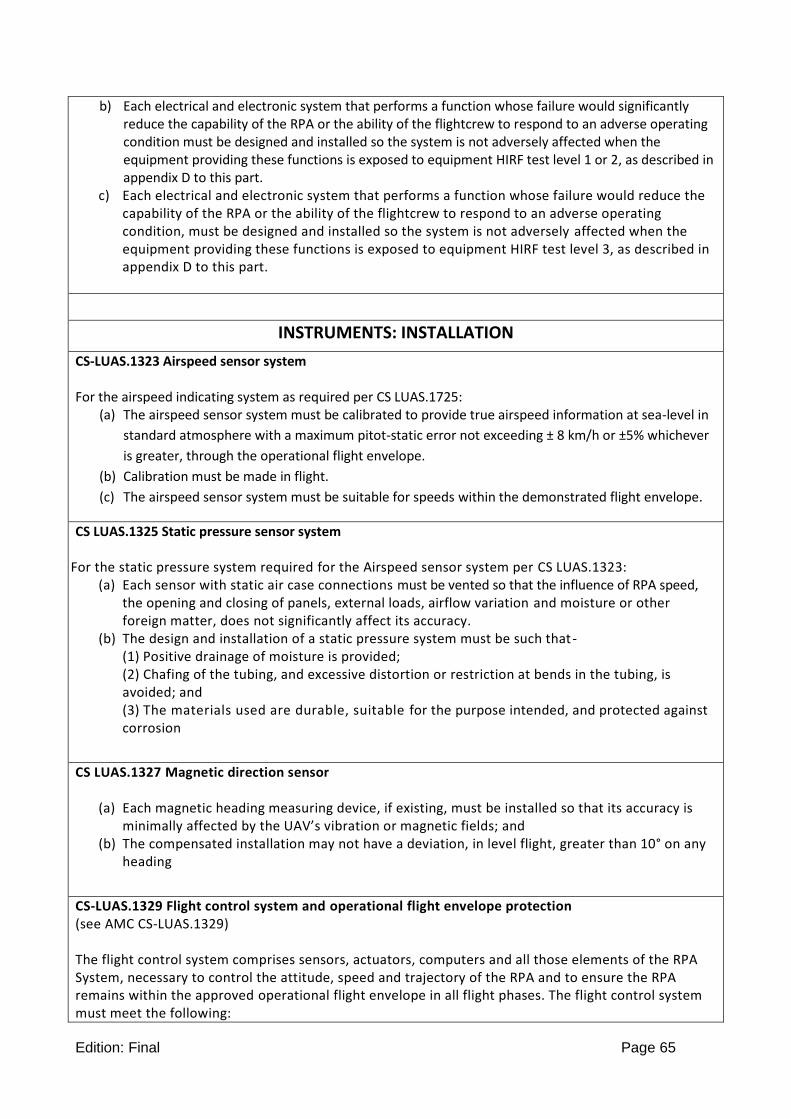
Edition: Final Page 65
b) Each electrical and electronic system that performs a function whose failure would significantly reduce the capability of the RPA or the ability of the flightcrew to respond to an adverse operating condition must be designed and installed so the system is not adversely affected when the equipment providing these functions is exposed to equipment HIRF test level 1 or 2, as described in appendix D to this part.
c) Each electrical and electronic system that performs a function whose failure would reduce the capability of the RPA or the ability of the flightcrew to respond to an adverse operating condition, must be designed and installed so the system is not adversely affected when the equipment providing these functions is exposed to equipment HIRF test level 3, as described in appendix D to this part.
INSTRUMENTS: INSTALLATION
CS-LUAS.1323 Airspeed sensor system For the airspeed indicating system as required per CS LUAS.1725:
(a) The airspeed sensor system must be calibrated to provide true airspeed information at sea-level in
standard atmosphere with a maximum pitot-static error not exceeding ± 8 km/h or ±5% whichever
is greater, through the operational flight envelope.
(b) Calibration must be made in flight.
(c) The airspeed sensor system must be suitable for speeds within the demonstrated flight envelope.
CS LUAS.1325 Static pressure sensor system For the static pressure system required for the Airspeed sensor system per CS LUAS.1323:
(a) Each sensor with static air case connections must be vented so that the influence of RPA speed, the opening and closing of panels, external loads, airflow variation and moisture or other foreign matter, does not significantly affect its accuracy.
(b) The design and installation of a static pressure system must be such that- (1) Positive drainage of moisture is provided; (2) Chafing of the tubing, and excessive distortion or restriction at bends in the tubing, is avoided; and (3) The materials used are durable, suitable for the purpose intended, and protected against corrosion
CS LUAS.1327 Magnetic direction sensor
(a) Each magnetic heading measuring device, if existing, must be installed so that its accuracy is minimally affected by the UAV’s vibration or magnetic fields; and
(b) The compensated installation may not have a deviation, in level flight, greater than 10° on any heading
CS-LUAS.1329 Flight control system and operational flight envelope protection (see AMC CS-LUAS.1329) The flight control system comprises sensors, actuators, computers and all those elements of the RPA System, necessary to control the attitude, speed and trajectory of the RPA and to ensure the RPA remains within the approved operational flight envelope in all flight phases. The flight control system must meet the following:
Edition: Final Page 66
(a) The flight control system must be designed so that a RPA crew of average skill can operate the
RPA System with acceptable workload during all phases of flight within the operational flight envelope.
(b) Where different RPA control modes can be activated by the RPA crew, the active control mode of the flight control system must be transmitted to the Ground Control Station.
(c) The RPA crews must have the opportunity to intervene at any time during the flight to manage safe control of the RPA, except :
(1) during emergency situations such as total loss of data link, (2) For RPAS with a automatic take-off capability, during the take-off phase after VR and before
achieving the minimum safe flight parameters, (3) For RPAS with an automatic landing capability, during landing phase after reaching the decision
point as defined by the applicant, (4) for RPA designed to be recovered by parachute, during the landing phase under parachute, (5) for rocket or catapult assisted take-off RPA, during the launch phase before reaching the limits
defined by the applicant.
(d) The flight control system must be designed and adjusted so that, within the range of adjustment (if any) available to RPA crew, it cannot produce an unsafe condition.
(e) The flight control system must apply limits to maneuvers to keep the RPA in the operational flight envelope as defined in CS-LUAS.23 as follows:
(1) Characteristics of each flight control system feature must be, appropriate to the phase of flight and type of maneuver
(2) Limit values of protected flight parameters must be compatible with the RPA structural limits, (f) When simultaneous envelope protection limits and any other flight control are engaged, adverse
coupling or adverse priority must not result. (g) Use of active flight controls for load alleviation, stability augmentation, and/or flutter suppression
must comply with Appendix C. (h) The borders and prioritization within the control system of the flight envelope protection
maintained by the flight control system must be clearly defined. (i) The flight control system must have a comprehensive self-test available and operating during all
phases of flight, including preflight. (j) Data exchanged between components of the flight control system or received from components
external to the flight control system must be verified for the integrity of the information prior to use. Information received from external sources must be verified within appropriate rate of change and range boundaries for the appropriate phase of flight before using in the computations.
(k) There must be protection against adverse interaction of integrated components, resulting from a malfunction.
(l) Feedback: The electronic flight control system must generate position data of all elements, necessary to control the attitude, speed and trajectory of the RPA and to ensure the RPA remains within the approved flight envelope in all flight phases. This position data must be transmitted to the Remote Pilot Station.
(m) Failure States: The electronic flight control system must generate a warning, if any change in envelope limiting or manoeuvrability is produced by single or multiple failures of the electronic flight control system not shown to be extremely improbable.
(n) The electronic flight control system must generate a warning, if an element, necessary to control the attitude, speed and trajectory of the RPA and to ensure the RPA remains within the approved flight envelope in all flight phases is not in a position required for the actual phase of flight.

Edition: Final Page 67
CS-LUAS.1331 Sensors using a power supply
For each sensor which failure would prevent continued safe flight and landing, the
following apply:
(a) A continued power supply monitoring is required..
(b) The installation and power supply systems must be designed so that-
(1) The failure of one sensor will not interfere with the proper supply of energy to the remaining sensors;
and
(2) The failure of the energy supply from one source will not interfere with the proper supply of energy from any other source.
CS LUAS.1337 Powerplant instruments
(a) Instruments and instrument lines
(1) Each powerplant instrument line must meet the requirements of CS LUAS.961 and 993 .
(2) Each line carrying flammable fluids under pressure must -
(i) Have restricting orifices or other safety devices at the source of pressure to prevent the escape of excessive fluid if the line fails; and
(ii) Be installed and located so that the escape of fluids would not create a hazard.
(3) Each powerplant instrument sensing device that utilises flammable fluids must be installed and located so that the escape of fluid would not create a hazard.
(b) Fuel flow meter system. If a fuel flow meter system is installed, each metering component must have
a means for bypassing the fuel supply if malfunction of that component severely restricts fuel flow.
(c) Oil quantity indicator. There must be means to indicate the quantity of oil in each tank on the ground
(including during the filling of each tank).
ELECTRICAL SYSTEMS AND EQUIPMENT
CS-LUAS.1351 General
(AMC-LUAS.1351 General)
(a) Electrical system capacity. Electrical equipment must be adequate for its intended use. In addition- (1) Electric power sources, their transmission cables, and their associated control and protective
devices must be able to furnish the required power at the proper voltage to each load circuit essential for safe operation; and
(2) Compliance with sub-paragraph (a)(1) must be shown by an electrical load analysis, or by electrical

Edition: Final Page 68
measurements that take into account the electrical loads applied to the electrical system in probable combinations and for probable durations.
(b) Function. For each electrical system, the following apply: (1) Each system when installed, must be -
(i) Free from hazards in itself, in its method of operation, and in its effects on other parts of the RPA; and
(ii) Protected from fuel, oil, water other detrimental substances, and mechanical damage. (2) Electric power sources must function properly when connected in combination or independently,
except that alternators may depend on a battery for initial excitation or for stabilization. (3) No failure or malfunction of any source may impair the ability of any remaining source to supply
load circuits essential for safe operation, except that the operation of an alternator that depends on a battery for initial excitation or for stabilization may be stopped by failure of that battery
(4) Each electric power source control must allow the independent operation of each source, except that controls associated with alternators that depend on a battery for initial excitation or for stabilization need not break connection between the alternator and its battery.
(c) Generating system, if installed. There must be at least one generator if the system supplies power to load circuits essential for safe operation. In addition- (1) Each generator must be able to deliver its continuous rated power; (2) Generator voltage control equipment must be able to dependably regulate each generator output
within rated limits; (3) Each generator must have a reverse current cutout designed to disconnect the generator from the
battery and from the other generators when enough reverse current exists to damage that generator.
(4) Each generator must have an overvoltage control designed and installed to prevent damage to the electrical system, or to equipment supplied by the electrical system, that could result if that generator were to develop an overvoltage condition; and
(5) There must be a means to give immediate warning to the RPA Pilot of a failure of any generator.
(d) NA (e) Fire resistance. Electrical equipment must be so designed and installed that in the event of a fire in the
engine compartment, during which the surface of the firewall adjacent to the fire is heated to 1100°C for 5 minutes or to a lesser temperature substantiated by the applicant, the equipment essential to continued safe operation and located behind the firewall will function satisfactorily and will not create and additional fire hazard. This may be shown by test or analysis.
(f) External power. If provisions are made for connecting external power to the RPA, and that external power can be electrically connected to equipment other than that used for engine starting, means must be provided to ensure that no external power supply having a reverse polarity, or reverse phase sequence, can supply power to the RPA's electrical system.
(g) It must be shown by analysis, tests or both, that the RPAS (RPA + Ground Station) can be operated safely in the approved operational envelope according CS-LUAS.23, for a period required to perform the emergency recovery procedure according CS-LUAS.1412 in case of normal (main) electrical power inoperative
CS-LUAS.1353 Storage battery design and installation
(a) Each storage battery must be designed and installed as prescribed in this paragraph.
(b) Safe cell temperatures and pressures must be maintained during any probable charging and discharging condition. No uncontrolled increase in cell temperature may result when the battery is recharged (after previous complete discharge) -

Edition: Final Page 69
(1) At maximum regulated voltage or power; (2) During a flight of maximum duration; and (3) Under the most adverse cooling condition likely to occur in service.
(c) Compliance with sub-paragraph (b) must be shown by test or experience with similar batteries and
installations.
(d) No explosive or toxic gases emitted by any battery in normal operation, or as the result of any probable malfunction in the charging system or battery installation, may accumulate in hazardous quantities within the RPA.
(e) No corrosive fluids or gases that may escape from the battery may damage surrounding structures or adjacent essential equipment.
(f) Each battery installation capable of being used to start an engine or auxiliary power unit must have provisions to prevent any hazardous effect on structure of essential systems that may be caused by the maximum amount of heat the battery can generate during a short circuit of the battery or its individual cells.
(g) Battery installations capable of being used to start an engine or auxiliary power unit must have - (1) A system to control the charging rate of the battery automatically so as to prevent battery
overheating; (2) A battery temperature sensing and over temperature warning system with means for disconnecting
the battery from its charging source in the event of an over-temperature condition; or (3) A battery failure sensing and warning system with a means for disconnecting the battery from its
charging source in the event of battery failure.
(h) In the event of a complete loss of the primary electrical power generating system, any battery or emergency power supply must be capable of providing enough electrical power to those loads that are essential to perform emergency procedures as defined in CS-LUAS.1412 during the associated time duration. This time duration includes the time needed for the RPA crew to recognise the loss of generated power and to take appropriate action.
(i) Any battery installation whose function is required for safe operation of the aircraft, must incorporate a monitoring and warning feature that will provide an indication to the appropriate flight crewmembers, whenever the state of charge (SOC) of the batteries have fallen below levels considered acceptable for dispatch of the aircraft.
(j) Where applicable, battery installations must be compliant with the appropriate national regulations regarding battery safety.
CS-LUAS.1357 Circuit protective devices (a) Protective devices, such as circuit breakers, must be installed in each electrical circuit other than-
(1) The main circuits of starter motors; and (2) Circuits in which no hazard is presented by their omission.
(b) A protective device for a circuit essential to flight safety may not be used to protect any other circuit.
(c) Where installed, each remotely resettable circuit protective device (“trip free” device in which the
tripping mechanism cannot be over-ridden by the operating control) must be designed so that

Edition: Final Page 70
(1) A remote operation to be done by the RPA crew is required to restore service after tripping; and (2) If an overload or circuit fault exists, the device will open the circuit regardless of the position of the
operating control. (3) Where automatic resettable circuit protection devices are used they must be designed so they
comply with (c) (2) and restore circuit integrity on removal of fault condition.
(d) If the ability to reset a circuit breaker is essential to safety in flight, that circuit must be located and identified so that it can be readily remotely reset in flight.
CS-LUAS.1359 Electrical system fire protection
(a) Components of the electrical system must meet the applicable fire protection requirements of CS-LUAS.861, CS-LUAS.863 and CS-LUAS.1182.
(b) Reserved
(c) Insulation on electrical wire and cable must be self-extinguishing when tested at an angle of 60° in accordance with approved methods. The average burn length must not exceed 76 mm (3 in) and the average flame time after removal of the flame source must not exceed 30 seconds. Drippings from the test specimen must not continue to flame for more than an average of 3 seconds after falling.
CS-LUAS.1361 RPA Electrical Load Shedding
(a) There must be an easily discernible and accessible means to allow ready shedding of electrical loads on the RPA.
(b) Load shedding must be achieved by disconnection of all electric power sources on the RPA from the power distribution systems except load circuits that are required for the emergency recovery capability according CS-LUAS.1412.
(c) The point of disconnection must be adjacent to the power sources controlled.
CS-LUAS.1365 Electric cables
(a) Each electric connecting cable must be of adequate capacity and correctly routed, attached and connected so as to minimize the probability of short circuits and fire hazards.
(b) Each cable and associated equipment that would overheat in the event of circuit overload or fault must be at least flame resistant.
CS-LUAS.1367 Switches
Each switch must be
(a) Able to carry its rated current;
(b) Constructed with enough distance or insulating material between current carrying parts and the housing so that vibration in flight will not cause shorting;
(c) Accessible on ground; and (d) Labeled as to operation and the circuit controlled

Edition: Final Page 71
LIGHTS
CS-LUAS.1384 External lights
(a) If external lights are installed for see & avoid purpose, then they must comply with paragraphs 23.1385 to 23.1401 of FAR/CS-23 as appropriate.
(b) For RPA where a) is impractical, a special condition applies.
EMERGENCY AND CONTINGENCY
CS-LUAS.1412 Emergency recovery capability
(see AMC CS-LUAS.1412)
(a) The RPAS must integrate an emergency recovery capability to prevent third party risk on ground or in the air in case the RPAS operation gets out of control that consists of: (1) a flight termination system, procedure or function that aims to immediately end the flight, or, (2) an emergency recovery procedure that is implemented through RPA crew command or by the on-
board systems. This may include automatic pre-programmed course of action to reach a predefined and unpopulated forced landing area, or,
(3) any combination of CS-LUAS.1412 (a) (1) and CS-LUAS.1412 (a) (2). (b) Based on the Total Hazard and Risk Assessment, the applicant must evaluate all operational and
technical failure and malfunction conditions and identify relevant scenarios where the emergency recovery capability must be provided to achieve the objectives identified under CS-LUAS.1412(a)
(c) The emergency recovery capability must function as intended throughout the demonstrated flight envelope under the most adverse environmental conditions
(d) Systems and components required for detection of critical failures, initiation or activation and proper functioning of the recovery procedure or termination system, must have independency from other systems as determined by CS-LUAS.1309.
(e) The emergency recovery capability must be protected from interference leading to inadvertent or unauthorized operation.
(f) When a forced landing area identified under CS-LUAS.1412(a)(2) is chosen for compliance with CS-LUAS.1412, the following must be furnished in the Flight Manual or other approved manual in Subpart G:
i. the characteristics of this area ii. The performance information to ensure the RPA will be able to reach the forced landing area.
CS-LUAS.1413 Command and Control Contingency
See AMC CS-LUAS.1413
(a) The RPA must initiate contingency procedures following a command and control function loss or a degraded status which no longer ensures controllability of the RPA by the remote pilot. This contingency procedures must be specified in the approved Flight Manual or other approved Manual for each operational situation
(b) The transition time before the RPA begins the contingency procedures due to the command and control function loss condition must be consistent with the requirements in CS-LUAS.1412 and must be specified for each operational situation in the approved Flight Manual or other approved Manual.
(c) There must be an alert for the RPAS crew, via a clear and distinct signal, for any loss or degradation of the command and control function
(d) The probability of failure of any system used for contingency planning after a command and control function loss or degradation must be commensurate with the hazard associated with loss or degradation of the command and control function, in accordance with CS-LUAS.1309

Edition: Final Page 72
COMMAND AND CONTROL DATALINK
CS-LUAS.1421 Command and Control Function See AMC CS-LUAS.1421 A RPAS must include a command and control function for control of the RPAS with the following functions:
(a) Transmittal of RPAS crew commands from the CONTROL STATION to the RPA (uplink), and
(b) Transmittal of RPA status data from the RPA to the CONTROL STATION (downlink).
MISCELLANEOUS EQUIPMENT
CS-LUAS.1431 Electronic equipment Electronic equipment and installations must be free from hazards in themselves, in their method of operation, and in their effects on other components.
CS-LUAS.1461 Equipment containing high energy rotors
(a) Equipment containing high-energy rotors must meet sub-paragraphs (b), (c), or (d).
(b) High-energy rotors contained in equipment must be able to withstand damage caused by malfunctions, vibration, abnormal speeds, and abnormal temperatures. In addition - (1) Auxiliary rotor cases must be able to contain damage caused by the failure of high energy rotor
blades; and (2) Equipment control devices, systems, and instrumentation must reasonably ensure that no operating
limitations affecting the integrity off high-energy rotors will be exceeded in service. (c) It must be shown by test that equipment containing high-energy rotors can contain any failure of a high
energy rotor that occurs at the highest speed obtainable with the normal speed control devices inoperative.
(d) Equipment containing high-energy rotors must be located where rotor failure will not adversely affect continued safe flight.
PAYLOAD
CS-LUAS.1481 Payload (AMC CS-LUAS.1481) a) An installed payload is a device or equipment installed on the RPA, which performs the mission
assigned. The payload comprises all elements of the air vehicle that are not necessary for flight but are carried for the purpose of fulfilling specific mission objectives.
b) A carried payload is a device or equipment carried by the RPA, which performs the mission assigned. The interfaces and retaining systems on the RPA designed to carry the payload must comply with the applicable requirements of CS-LUAS.

Edition: Final Page 73
AUTOMATIC TAKE-OFF SYSTEM - AUTOMATIC LANDING SYSTEM
CS-LUAS.1490 AUTOMATIC TAKE-OFF SYSTEM - AUTOMATIC LANDING SYSTEM
(See AMC CS-LUAS.1490)
When a RPAS, designed for conventional take-off and landing on a runway is equipped with an automatic take-off system or an automatic landing system or both, it should meet the following requirements
(a) Once the automatic take-off or landing mode has been engaged, the RPAS crew monitors the whole
process from the Remote Pilot Station, RPS, via the command and control data link, but is not required
to perform any manual “piloting action”, except manual abort, where required, as per provisions of CS-
LUAS.1492.
(b) The automatic function shall not degrade the overall redundancy or level of safety of the flight control
system. When off-board sensors are utilized via data-links, the continued safe flight of the RPA must
be ensured in the event of a total loss or degradation of the command and control function
(c) The automatic system shall cause no unsafe sustained oscillations or undue attitude changes or
control activity as a result of configuration or power changes or any other disturbance to be expected
in normal operation.
(d) Automatic take-off system or automatic landing system data and status must be transmitted to the
RPS.
(e) Take-off
In case of failure that could adversely affect safe flight or exceedance from predefined limits occurring
during the take-off run at every speed up to the rotation speed VR or the proper refusal speed (if
applicable), an automatic abort function shall be provided to stop the RPA on the runway.
(f) Landing
In case of failure or exceedance from the predefined limits of a convergence window occurring during
the approach, an automatic go around function shall be provided above a certain height called
“Decision Point” in accordance with CS-LUAS.1329(c)(3), at which such a go around may be safely
performed (i.e. with no ground contact that may damage the RPA).
CS-LUAS.1492 Manual abort function
Where a RPAS is designed for conventional take-off and landing on a runway, it must include the following function :
(a) The automatic system must incorporate a manual abort function. Its control shall be easily accessible
to the RPAS crew in order to
(1) stop the RPA on the runway during the take-off run at every speed up to refusal speed or rotation
speed VR, whichever is less.
(2) where it is safe to perform, initiate a go around during the landing phase at every height down to a
Decision Point.
(b) Specific go around procedure shall be provided in the RPA System Flight Manual under CS-LUAS.1585.

Edition: Final Page 74
SUBPART G - OPERATING LIMITATIONS AND INFORMATION
GENERAL
CS-LUAS.1501 General (a) Each operating limitation specified in CS-LUAS. 1505 to 1527 and other limitations and information
necessary for safe operation must be established. (b) The operating limitations and other information necessary for safe operation must be made available
to the crew members as prescribed in CS-LUAS.1541 to 1589.
OPERATING LIMITATIONS
CS-LUAS 1505 Airspeed limitations
(a) The never-exceed speed VNE must be established so that it is –
(1) Not less than 0·9 times the minimum value of VD allowed under CS-LUAS.335; and
(2) Not more than the lesser of –
(i) 0·9 VD established under CS-LURS.335; or
(ii) 0·9 times the maximum speed shown under CS-LURS 251.
(b) The maximum structural cruising speed VNO must be established so that it is –
(1) Reserved
(2) Not more than the lesser of –
(i) VC established under CS-LUAS.335 or-
(ii) 0·89 VNE established under sub-paragraph (a) of this paragraph.
(3) The maximum speed allowed by the flight envelope protection maintained by the flight control
system is equal or less than VNO.
(c) Sub-paragraphs (a) and (b) do not apply to Turbine or high-speed RPA’s . For those RPA’s, a maximum operating limit speed (VMO/MMO airspeed or Mach number, whichever is critical at a particular altitude) must be established as a speed that may not be deliberately exceeded in any regime of flight (climb, cruise, or descent) unless a higher speed is authorised for flight test or pilot training operations. VMO/MMO must be established so that it is not greater than the design cruising speed VC/MC and so that it is sufficiently below VD/MD and the maximum speed shown under CS LUAS.251 to make it highly improbable that the latter speeds will be inadvertently exceeded in operations. The speed margin between VMO/MMO and VD/MD or the maximum speed shown under CS LUAS.251 may not be less than the speed margin established between VC/MC and VD/MD under CS LUAS.335(b), or the speed margin found necessary in the flight tests conducted under CS LUAS.253. The maximum speed allowed by the flight envelope protection maintained by the flight control system must be equal or less than VMO/MMO.

Edition: Final Page 75
CS-LUAS.1507 Manoeuvring speed
(a) The manoeuvring speed VA, determined under CS-LUAS.335, must be established as an operating
limitation.
(b) For turbine or high-speed RPA’s, instead of (a), the maximum operating maneuvering speed, VO, must
be established as an operating limitation. VO is a selected speed that is not greater than VS√n
established in CS LUAS.335(c).
CS LUAS.1511 Flap extended speed
(a) The flap extended speed VFE must be established so that it is –
(1) Not less than the minimum value of VF allowed in CS LUAS.345 (b); and
(2) Not more than VF established under CS LUAS.345 (a), (c) and (d).
(b) Additional combinations of flap setting, airspeed and engine power may be established if the
structure has been proven for the corresponding design conditions.
CS LUAS.1513 Minimum control speed
The minimum control speed(s) VMC, within the operational flight envelope, must be established as an operating limitation(s).
CS-LUAS.1519 Weight and centre of gravity
The weight and centre of gravity ranges, determined under CS-LUAS.25 and 27 must be established as operating limitations.
CS-LUAS.1521 Powerplant limitations
(a) General. The powerplant limitations prescribed in this paragraph must be established so that they do
not exceed the corresponding limits established for the engine.
(b) Take-off operation. The powerplant take-off operation must be limited by -
(1) The maximum rotational speed, which may not be greater than -
(i) The maximum value determined by the propeller design; or
(ii) The maximum value shown during the type tests;
(2) The maximum allowable value of the critical engine parameters;
(3) The time limit for the use of the power corresponding to the limitations established in
subparagraph (b)(1) and (2);
(c) Continuous operation. The continuous operation must be limited by-
(1) The maximum rotational speed which may not be greater than-
(i) The maximum value determined by the rotor design; or
(ii) The maximum value shown during the type tests;
(2) The maximum allowable value of the critical engine parameters;
(d) Fuel grade or designation. The minimum fuel grade (for reciprocating engines), or fuel designation
(for turbine engines), must be established so that it is not less than that required for the operation of
the engines within the limitations in sub-paragraphs (b) and (c) .

Edition: Final Page 76
CS-LUAS.1523 Minimum RPAS Crew
The minimum RPAS crew must be established so that it is sufficient for safe operation considering:
(a) The workload on individual crew members
(b) Each crew member workload and role must be determined considering the following:
(1) Flight path control
(2) Separation and collision avoidance with ground obstacle or air traffic
(3) Navigation
(4) Communications
(5) Operation and monitoring of all RPAS systems required for continued safe flight and landing
(6) Tasks not related to piloting (e.g. payload operation)
(7) Command decisions and
(8) The accessibility and ease of operation of necessary controls by the appropriate crew member
during all normal and emergency operations when at the crew member flight station.
(9) The kinds of operation authorized under CS-LUAS.1525.
(10) Crew required for ground operation.
CS-LURS.1525 Kinds of operation
The kinds of operation to which the RPA is limited, taking into account the installed equipment, are established as part of the certification.
CS-LUAS.1527 Maximum operating altitude
The maximum altitude up to which operation is allowed, as limited by flight, structural, powerplant, functional, or equipment characteristics, must be established.
CS-LURS.1529 Instructions for Continued Airworthiness
(See Appendix A)
Instructions for Continued Airworthiness in accordance with Appendix A must be prepared and accepted by the certifying authority.
MARKINGS AND PLACARDS
CS-LUAS.1541 General
(a) The RPA must contain-
(1) The markings and placards specified in CS-LUAS.1557 and CS-LUAS.1749 to CS-LUAS-1759, and (2) Any additional information, instrument markings, and placards required for the safe
operation of the RPA if it has unusual design, operating or handling characteristics. (3) Placards intended for use by the flight crew should be placed at an appropriate location in the
control station.
(b) Each marking and placard prescribed in sub-paragraph (a) -
(1) Must be displayed in a conspicuous place; and (2) May not be easily erased, disfigured, or obscured.
(c) The units of measurement used on placards must be the same as those used on the indicators.
Edition: Final Page 77
CS-LUAS.1557 Miscellaneous markings and placards (a) Cargo compartments, and ballast location. Each cargo compartment, and each ballast location must
have a placard stating any limitations on contents, including weight, that are necessary under the loading requirements.
(b) Fuel and oil filler openings. The following apply: (1) Fuel filler openings must be marked at or near the filler cover with the minimum fuel grade, fuel
designation, fuel capacity of the tank, and for each 2-stroke engine without a separate oil system, fuel/oil mixture ratio.
(2) Oil filler openings must be marked at or near the filler cover; (i) With the grade; and (ii) Whether the oil is detergent or non-detergent.
(c) Fuel tanks. The useable fuel capacity in volumetric units of each tank must be marked at the selector
and on the fuel quantity indicator.
(d) .Not applicable (e) The system voltage of each direct current electrical installation must be clearly marked adjacent to its
external power connection. (f) When installed, equipment that may be hazardous to people on the ground must be clearly
marked .
FLIGHT MANUAL AND APPROVED MANUAL MATERIAL
CS-LUAS.1581 General (a) Furnishing information. A Flight Manual must be furnished with each RPAS, and it must contain the
following: (1) Information required by CS-LUAS.1583 through 1589. (2) Other information that is necessary for safe operation because of design, operating, or handling
characteristics. (3) Information that is necessary for the FTS per CS-LUAS.1412 and the contingency procedure per CS-
LUAS.1413.
(b) Approved information. Each part of the manual listed in CS-LUAS.1583 through 1589, that is appropriate to the RPAS, must be furnished, verified, and approved, and must be segregated, identified, and clearly distinguished from each unapproved part of that manual.
(c) Non-approved Information. Non-approved information must be presented in a manner acceptable to the Certifying Authority.
(d) Units. The units of measurement used in the manual must be the same as those used on the indicators.
(e) Table of contents. Each RPAS Flight Manual must include a table of contents if the complexity of the manual indicates a need for it.

Edition: Final Page 78
CS-LUAS.1583 Operating limitations (a) Airspeed limitations . The following information must be furnished
(1) Information necessary for the marking of the airspeed limits on the indicator, as required in CS-LUAS 1708(b) and the significance of the colour coding used on the indicator.
(2) The speeds VA and VMC required by CS-LUAS.1507 and 1513. (3) The speeds VLO , VLE where appropriate
(b) The minimum and maximum Weight according to CS-LUAS.25 and CS-LUAS.29 . (c) Centre of gravity . The established c.g. limits required by CS-LUAS 27 must be furnished. (d) Reserved. (e) Flight load factors . Manoeuvring load factors: the following must be furnished:
(1) The factors corresponding to point A and point C of figure 1 of CS-LUAS 333 (b), stated to be applicable at VA .
(2) The factors corresponding to point D and point E of figure 1 of CS-LUAS 333 (b) to be applicable at VNE.
(3) The factor with wing flaps extended as specified in CS-LUAS 345. (f) Kinds of operation . The kinds of operation in which the RPA may be used, must be stated. The
minimum equipment required for the operation must be listed. (g) Powerplant limitations . The following information must be furnished:
(1) Limitation required by CS- LUAS 1521. (2) Limitations required by CS- LUAS.903, and 909 if applicable (3) Information necessary for marking the instruments required by CS-LUAS 1708. (4) Fuel and oil designation. (5) For two-stroke engines, fuel/oil ratio.
(h) Placards. Placards required by CS-LUAS 1541 and 1557 must be presented. (i) Environmental Limitations. The environmental limitations as considered in CS-LUAS.23 must be
stated
CS-LUAS.1585 Operating procedures Information concerning normal and emergency procedures and other pertinent information necessary for safe operation must be furnished, including –
(a) The minimum speeds based on the operational flight envelope.
(b) Reserved
(c) If an automatic take-off or landing system is used, the specific go around procedure as required by CS-
LUAS.1492
(d) Recommended recovery procedure to recover from an inadvertent spin.
(e) Special procedures to start the engine in flight, if necessary.
(f) Information on the total quantity of usable energy capacity, and conditions under which the full
amount of usable energy capacity in each energy storage can safely be used.
(g) Command and control datalink management. Where the RPA System is designed for RPA handover
between multiple control stations, this must include the command and control functions that are
transferred during handover, as required by CS-LUAS.1775
Edition: Final Page 79
CS-LUAS.1587 Performance information (see AMC CS-LUAS.1587) (a) General . For each RPA, the following information must be furnished
(1) The take-off distance determined under CS-LUAS.53, the airspeed at the 15 m height, the
aeroplane configuration (if pertinent), the kind of surface in the tests, and the pertinent
information with respect to cowl flap position, use of flight path control devices, and use of the
landing gear retraction system.
(2) The landing distance determined under CS-LUAS.53, the aeroplane configuration (if pertinent), the
kind of surface used in the tests, and the pertinent information with respect to flap position and
the use of flight path control devices.
(3) The steady rate or gradient of climb determined under CS-LUAS.53, the airspeed, power, and the
aeroplane configuration.
(4) The calculated approximate effect on take-off distance (sub-paragraph (a)( 1) of this paragraph),
landing distance (subparagraph (a)(2) of this paragraph), and steady rates of climb (sub-paragraph
(a)(3) of this paragraph), of variations in altitude and temperature in ISA.
(5) The maximum atmospheric temperature at which compliance with the cooling provisions of CS-
LUAS 1041 is shown.
(b) Performance information for parachute landing according to CS-LUAS.290 to 292
(c) Information concerning normal procedures
(1) The demonstrated crosswind velocity and procedures and information pertinent to operation of
the aeroplane in crosswinds, and
(2) The airspeeds, procedures, and information according to CS-LUAS.53
(d) An indication of the effect on take off and landing distance of operation on other types of runway surfaces (e.g. grass, gravel) when dry.
(e) The launch performance according CS-LUAS.280(b) (f) Information about the irreversible catapult or rocket ignition phase according CS-LUAS.280(d). (g) Information about the launch safety area according CS-LUAS.283(b)
(h) The maximum unobstructed range of the command and control function
(i) The command and control transaction time
(j) The contingency information according to CS-LUAS.1413.
(k) The Emergency Recovery Information according to CS-LUAS.1412(f)
(l) The RPS power supply parameters as required by CS-LUAS.1703(b)
(m) Battery information as required by CS-LUAS.985(d)
CS-LUAS.1589 Loading information There must be loading instructions for each possible loading condition between the maximum and minimum weights determined under CS-LUAS.25 that can result in a centre of gravity beyond any extreme prescribed in CS-LUAS.27.

Edition: Final Page 80
SUBPART H - DETECT AND AVOID
RESERVED
SUBPART I - REMOTE PILOT STATION
RPS GENERAL REQUIREMENTS
CS-LUAS.1700 General (a) The RPS must guarantee correct functioning of all functions necessary to safely accomplish all design
missions under all conditions of the approved operational envelope defined in CS-LUAS. 23, including the performance of emergency and recovery procedures.
(b) A communication system should be provided as agreed by the Certifying Authority in order to allow a two-way communication with the ATC in airspace where ATC communication is required
CS-LUAS.1702 Systems and equipment used by the crew See AMC CS-LUAS.1702 (to be derived from AMC 25.1302) This paragraph applies to equipment intended for crew members’ use in the operation of the RPA at the control station. This installed equipment must be shown, individually and in combination with other such equipment, to be designed so that qualified crew members trained in its use can safely perform their tasks associated with its intended function by meeting the following requirements: (a) controls must be installed to allow accomplishment of these tasks and information necessary to
accomplish these tasks must be provided. (b) controls and information intended for crew use must:
(1) Be presented in a clear and unambiguous form, at resolution and precision appropriate to the task. (2) Be accessible and usable by the crew in a manner consistent with the urgency, frequency, and duration of their tasks, (3) Be plainly marked as to its function and method of operation, except these controls whose function is obvious, and (4) Enable crew awareness, if awareness is required for safe operation, of the effects on the RPA or systems resulting from crew actions.
(c) Operationally-relevant behaviour of the installed equipment must be: (1) Predictable and unambiguous, and (2) Designed to enable the crew to intervene in a manner appropriate to the task.
(d) To the extent practicable, installed equipment must enable the crew to manage errors resulting from the kinds of flight crew interactions with the equipment that can be reasonably expected in service, assuming the flight crew is acting in good faith.
(e) The equipment must allow the crew member to perform his duties without unreasonable concentration or
fatigue;

Edition: Final Page 81
CS-LUAS.1703 Remote Pilot Station (RPS) Electrical Systems (a) Remote Pilot Station Electrical Systems
(1) Each electrical system in the RPS must be:
i) Free from hazards in itself, in its method of operation, and in its effects on other parts of the RPS
ii) So designed that the risk of electrical shock to RPAS crew in the RPS and other ground personnel is reduced to a minimum.
iii) Designed to be protected against EMI coming from the operational environment to ensure normal operation.
(2) the RPS must be adequately conditioned for the operational environment
(b) Remote Pilot Station Power Supply
(1) The RPS power supply must be designed such that the operations in normal and failure conditions
shall not lead to an unsafe condition; the corresponding minimum RPS power required must be
stated in the RPAS operating manual.
(2) A warning shall be immediately provided to the RPAS crew for any RPS power supply failure which
could result in an unsafe condition in any phase of RPA flight, including landing and take off
(3) The parameters deemed as essential for flight safety and the supporting infrastructure required
for the RPS must be stated in the RPAS Flight Manual or respective manual of the RPS
RPA CONTROL ON RPS CS-LUAS.1705 Ground Control Station controls (AMC LUAS.1705)
(a) General requirements
Controls must be designed to-
(1) Prevent the inadvertent entry of foreign objects into places where they would jam the system
(2) Maintain a set position and must be able to maintain any set position without constant attention; or tendency to creep due to vibration.
(b) Energy for propulsion shutoff (1) Where the RPA contains explosive or flammable material, there must be a means in the RPS to
immediately shutoff the energy required by the RPA for propulsion
(2) There must be means to guard against inadvertent operation of each shutoff, and to make it
possible for the remote crew to re-engage it in flight after it has been shutoff.
(3) The control must be within easy reach of appropriate remote crewmembers
(c) Electrical Energy Shutoff (1) There must be a master switch or switches arranged to allow ready disconnection of all electric
power sources on the RPA. The point of disconnection must be adjacent to the sources controlled by the switch.
(2) The master switch arrangement must be so installed that it is easily discernible and accessible to the remote Pilot during operation.

Edition: Final Page 82
(d) Engine controls Means must be provided on the RPS for the controlling, monitoring, and emergency shutdown of each installed engine.
RPA INDICATION ON RPS CS-LUAS.1707 Indication general
(a) Each indication of a valve, solenoid or other actuator required for safety shall indicate the effect of the operation and not the commanded position of the control device.
(b) In case the effect of the operation of the valve, solenoid or other actuator does not correspond with the commanded position of the control device, a warning must be announced to the crew.
CS LUAS.1708 Indication markings (a) For each required instrument, that indicates a range of operation, maximum (or minimum) and
normal operating values must be indicated to the RPAS crew, taking into account color requirements
as per 1722.
(b) Each airspeed indicator must be marked as specified in subparagraph (a) of this paragraph, with the
marks located at the corresponding indicated airspeed.
The following markings must be made:
(1) For the limiting speeds defined by the operating envelope, a red line. (2) For the normal operating envelope, a green range
CS-LUAS.1721 Arrangement and visibility
(AMC LUAS.1721)
(a) Each flight, navigation, powerplant instrument and system status information provided, must be
clearly arranged and plainly visible to the remote Pilot.
(b) Instruments must be designed to support the foreseen operating conditions without impairing
readability or accuracy of any instrument
CS-LUAS.1722 Flight Crew Alerting (AMC LUAS.1722) (a) Flight crew alerts must:
(1) provide the flight crew with the information needed to: (i) identify non-normal operation or aeroplane system conditions, and (ii) determine the appropriate actions, if any; (2) be readily and easily detectable and intelligible by the flight crew under all foreseeable operating conditions, including conditions where multiple alerts are provided; (3) be removed when the alerting condition no longer exists
(b) Alerts must conform to the following prioritisation hierarchy based on the urgency of flight
crew awareness and response:
(1) Warning: For conditions that require immediate flight crew awareness and immediate flight
crew response.
(2) Caution: For conditions that require immediate flight crew awareness and subsequent flight

Edition: Final Page 83
crew response.
(3) Advisory: For conditions that require flight crew awareness and may require subsequent
flight crew response
(c) If warning, caution or advisory lights are installed in the Control station, they must, unless otherwise
approved by the Certification authority, be -
(1) Red, for warning l ights ( l ights indicating a hazard which may require immediate corrective action);
(2) Amber, for caution lights (lights indicating the possible need for future corrective action); (3) Green, for safe operation lights; and (4) Any other colour, including white, for lights not described in sub-paragraphs (a) through (c),
provided the colour differs sufficiently from the colours prescribed in sub-paragraphs (a) to (c) to avoid possible confusion.
CS LUAS.1725 Flight and navigation instruments (AMC LUAS.1725)
(a) The following are the minimum required flight and navigational data that must be displayed at all times in the Ground Control Station at an update rate consistent with safe operation:
(1) Indicated airspeed; (2) Altitude; (3) Attitude (4) Heading or track; (5) Geographical RPA position
(b) The following are the minimum required flight and navigational data that shall be selectable or available when requested by the remote pilot for display in the ground control station at an update rate consistent with safe operation:
(1) Ground speed; (2) Airspeed minimum and maximum limitations and corresponding speed warnings; (3) Vertical speed; (4) Navigation system status;
CS-LUAS.1729 Flight control system indication (see AMC CS-LUAS.1729)
(a) There must be a means in the Remote Pilot Station to indicate to the RPA crew the active RPA control mode of the flight control system
(b) RPAS elements to control attitude, speed and trajectory, as well as to ensure RPA remains in the
approved flight envelope shall perform as intended. When any RPAS element is not in the position required, it must be indicated to RPAS crew by adequate means.
(c) When single (or multiple) failure not shown to be extremely improbable, affects the flight control
system or limits the flight envelope or maneuverability, the RPAS crew must be alerted. (d) An aural or equally effective warning devices must be provided to inform the crew if an element,
necessary to control the attitude, speed and trajectory of the RPA and to ensure the RPA remains within the approved flight envelope in all flight phases is not in a position required for the actual phase of flight.
Edition: Final Page 84
CS-LUAS.1737 Energy capacity instruments for propulsion (See AMC CS-LUAS.1737(a)(2)
(a) There must be a calibrated indication of the usable energy quantity for the propulsion provided to the
remote crew.
(b) There must be a warning and indication to the remote crew to:
(1) Indicate the system minimum energy capacity, required for safe operation (2) Indicate a failure in the energy generating, supplying or storage system
CS-LUAS.1749 Powerplant instruments (AMC LUAS.1749)
The following shall be provided: (a) All instrumentation required to assure operation of the engine within the certified limits and (b) RPA crew alerts of any failures that require RPA crew awareness and intervention.
CS-LUAS.1752 RPA electrical systems warning and indication
(a) There must be a means to give immediate warning to the RPAS crew of a failure of any RPA electrical power generating device.
(b) A means must exist in the control station to indicate to the RPAS crew the electric power system quantities essential for safe operation
(c) A warning which is unambiguous and clearly distinguishable to the RPAS crew shall be immediately provided for any control station power supply failure which could result in an unsafe condition in any phase of RPAS flight, including landing and take off
CS-LUAS.1759 Limitations placard
There must be an indication in clear view of the RPA crew stating in the RPS that the RPA must be operated in accordance with the RPAS Flight Manual;
C2 LINK INDICATION ON RPS
CS-LUAS.1761 Aircraft and Control Station pairing There must be a positive indication at the control station that the intended aircraft has been paired and full control established prior to flight.
CS-LUAS.1763 C2 Link Status The status of the Command & Control Link system as required by CS-LUAS.1421 (a) and (b)
MULTI RPS AND RPA CS-LUAS.1775 Control station handover (See AMC.1775 (b), AMC.1775 (c) and AMC.1775 (d)) Where the RPA System is designed for RPA hand over between multiple control stations: (a) Coordination between both control stations is required before handover. Effective pairing must
be monitored and indicated to both RPS stations. The in-control control station must be clearly identified to all RPAS crew members. Definition of coordination means and processes must be agreed by the Certification Authority.

Edition: Final Page 85
(b) Positive control must be maintained during handover. (c) The command and control functions that are transferred during handover must be defined in the
RPA System Flight Manual. (d) Handover between multiple control stations must not lead to unsafe conditions.
APPENDIX A - INSTRUCTIONS FOR CONTINUED AIRWORTHINESS
A.LUAS.1 General
(a) This appendix specifies requirements for the preparation of instructions for continued airworthiness
as required by CS-LUAS. 1529.
(b) The instructions for continued airworthiness for each RPAS must include the instructions for
continued airworthiness for each engine and propeller (hereinafter designated "products"), for each
appliance required by any applicable CS or operating rule, and any required information relating to
the interface of those appliances and products with the RPAS. If instructions for continued
airworthiness are not supplied by the manufacturer of an appliance or product installed in the RPAS,
the instructions for continued airworthiness for the RPAS must include the information essential to
the continued airworthiness of the RPAS.
A.LUAS.2 Format
(a) The instructions for continued airworthiness must be in the form of a manual or manuals as
appropriate for the quantity of data to be provided.
(b) The format of the manual or manuals must provide for a practical arrangement.
A.LURS.3 Content
The contents of the manual or manuals must be prepared in the English language. The instructions for continued airworthiness must contain the following manuals or paragraphs, as appropriate, and information:
(a) RPAS maintenance manual or paragraph:
(1) Introduction information that includes an explanation of the RPAS's features and data to the
extent necessary for maintenance or preventive maintenance.
(2) A description of the RPAS and its systems and installations including its engine, propellers, and
appliances.
(3) Basic control and operation information describing how the RPAS components and systems are
controlled and how they operate, including any special procedures and limitations that apply.
(4) Servicing information that covers details regarding servicing points, capacities of tanks, reservoirs,
types of fluids to be used, pressures applicable to the various systems, location of access panels for
inspection and servicing, locations of lubrication points, the lubricants to be used, equipment
required for servicing, tow instructions and limitations, mooring, jacking, and levelling information.
(b) Maintenance instructions
(1) Scheduling information for each part of the RPAS and its engines, propellers, accessories,
instruments and equipment that provides the recommended periods at which they should be
cleaned, inspected, adjusted, tested, and lubricated, and the degree of inspection, the applicable
wear tolerances and work recommended at these periods. However, it is allowed to refer to an

Edition: Final Page 86
accessory, instrument or equipment manufacturer as the source of this information if it is shown
that the item has an exceptionally high degree of complexity requiring specialized maintenance
techniques, test equipment, or expertise. The recommended overhaul periods and necessary cross
references to the airworthiness limitations paragraph of the manual must also be included. In
addition, an inspection program that includes the frequency and extent of the inspections
necessary to provide for the continued airworthiness of the RPAS must be included.
(2) Troubleshooting information describing problem malfunctions, how to recognize those
malfunctions, and the remedial action for those malfunctions.
(3) Information describing the order and method of removing and replacing products and parts with
any necessary precautions to be taken.
(4) Other general procedural instructions including procedures for system testing during ground
running, symmetry checks, weighing and determining the centre of gravity, lifting and shoring, and
storage limitations.
(5) Procedures and instructions for parachute handling where applicable.
(c) Diagrams of structural access plates and information needed to gain access for inspections when
access plates are not provided.
(d) Details for the application of special inspection techniques including radiographic and ultrasonic
testing where such processes are specified.
(e) Information needed to apply protective treatments to the structure after inspection.
(f) All data relative to structural fasteners such as identification, discard recommendations, and torque
values.
(g) A list of special tools needed.
(h) The instruction for transportation, assembly/disassembly, reconfiguration, storage and handling
A.LUAS.4 Airworthiness Limitations Section
The instructions for continued airworthiness must contain a section titled Airworthiness Limitations, that is segregated and clearly distinguishable from the rest of the document. This section must set forth each mandatory replacement time, structural inspection interval, and related structural inspection procedure approved under CS-LUAS.572. If the instructions for continued airworthiness consists of multiple documents, the section required by this sub-paragraph must be included in the principal manual. This section must contain a legible statement in a prominent location that reads:
"The airworthiness limitations section is approved and variations must also be approved".
APPENDIX B - ENGINES STRUCTURES
GENERAL
B-LUAS.1 Applicability (See AMC CS-LUAS.1) (a) This appendix B is applicable to engines for fixed wing Remotely Piloted Aircraft (RPA) with a
Maximum Take-off Mass (MTOM) not exceeding 750 kg. (b) Where specific requirements for turbine engines are mentioned, the following restrictions are
applicable to simplify the certification requirements: (1) The engine certificated under these requirements is used to power fixed wing Remotely Piloted
Aircraft Systems only.

Edition: Final Page 87
(2) no bleed air, no reverse functions (3) no flight in icing or hail conditions (4) no aerobatic operation (5) the turbine is not used to drive accessories, that are essential for any other means than the
turbine itself
B-LUAS.3 Instruction manual All necessary instructions, information and requirements for the safe and correct operation and interface between the engine and the aircraft must be promulgated.
B-LUAS.5 Engine power ratings and operating limitations Engine power ratings and operating limitations must be based on the operating conditions demonstrated during the tests prescribed in this appendix B.
B-LUAS.7 Selection of Engine power ratings (a) Requested engine power ratings must be selected by the applicant. (b) Each selected rating must be for the lowest power that all engines of the same type may be expected
to produce under the conditions used to determine that rating.
DESIGN AND CONSTRUCTION
B-LUAS.9 Installation The engine and its installation must not introduce unacceptable hazards to the aircraft under all operating conditions
B-LUAS.11 Materials and fabrication methods The fabrication process and materials used in the construction of the engine must be suitable for their use and result in known and reproducible structural behavior. Any changes in material performance related to the operational environment must be accounted for.
B-LUAS.20 Functioning
The engine must produce, within its stated limits, the thrust or power demanded of it at all required flight conditions, taking into account environmental effects and conditions.
B-LUAS.21 Engine Control System (a) The engine control system must operate with the ease, smoothness, and positiveness appropriate to
its functions. (b) It must also be demonstrated that the engine is capable to function properly in case of exposure to
radio magnetic interference. The demonstrated levels have to be included in the Installation Instructions.
B-LUAS.23 Engine Mounting System Each engine component which forms part of the engine mounting and any other parts of the engine liable to be critically affected must, when the engine is properly supported by a suitable engine-mounting structure, (a) Be able to support limit loads without detrimental permanent deformation. At any load up to limit
loads, the deformation may not interfere with safe operation. (b) Be able to support ultimate loads without failure.

Edition: Final Page 88
B-LUAS.25 Fire prevention The design and construction of the engine and the materials used must minimize the probability of the occurrence and spread of fire during normal operation and failure conditions and must minimize the effects of such a fire.
B-LUAS.27 Durability (a) Engine design and construction must minimize the probability of occurrence of an unsafe condition of
the engine between overhauls. The effects of cyclic loading, environmental and operational degradation, including subsequent part failures must not reduce the integrity of the engine below acceptable levels.
(b) There must be means to allow the close examination of each part that requires recurring inspection, adjustment for proper alignment and functioning, lubrication or rigging and de -rigging.
B-LUAS.29 Engine cooling Engine design and construction must provide the necessary cooling under conditions in which the aircraft is expected to operate.
B-LUAS.31 Accessory attachment Each accessory drive and mounting attachment must be designed and constructed so that the engine will operate properly with the accessories attached. The design of the engine must allow the examination, adjustment or removal of each essential engine accessory.
B-LUAS.33 Vibration (See AMC -B-LUAS.33) The engine must be designed and constructed to function throughout its normal operating range of speeds and engine powers without inducing excessive stress in any of the engine parts because of vibration and without imparting excessive vibration forces to the structure of the aircraft.
B-LUAS.35 Ignition Except for compression ignition engines, the engine must be equipped with a dual ignition system having all the magnetic and electrical circuits entirely independent, or with a single ignition system of at least equal reliability to a dual system. The ignition system must function throughout the complete operating range of the engine under all starting and flight conditions. The system must be designed to be switched on and off under all starting and flight conditions
B-LUAS.37 Fuel and induction system (a) Each fuel specification to be approved, including any additive, and the associated limitations in flow,
temperature and pressure that ensure proper engine functioning under all intended operating conditions must be declared and substantiated.
(b) The fuel system of the engine must be designed and constructed to supply the appropriate mixture of fuel to the combustion chambers throughout the complete operating range of the engine under all starting, flight and atmospheric conditions. It should also keep the rotational speed in the range, defined by the manufacturer.
B-LUAS.39 Lubrication system The lubrication system of the engine must be designed and constructed so that it will function properly in all attitudes and atmospheric conditions in which the RPAS is expected to operate.
B-LUAS.41 High Energy Rotor Containment For each high-energy engine rotor, the engine must be designed to provide containment.

Edition: Final Page 89
BENCH TESTS
B-LUAS.43 Calibration test (See AMC B-LURS.43) Each engine must be subjected to the calibration tests necessary to establish its power characteristics and the conditions for the endurance test specified in B-LUAS.47 (a) to (d). The results of the power characteristics calibration tests form the basis for establishing the characteristics of the engine over its entire operating range Power ratings are based on standard atmospheric conditions at sea level
B-LUAS.45 Detonation test (spark ignition only) A test must be conducted using the dual ignition system and must be repeated using each separate ignition system alone to determine whether it can function without detonation throughout the range of intended conditions of operation.
B-LUAS.47 Endurance test (See AMC B-LUAS.47) (a) The engine must be subjected to an endurance test that includes a total of 50 hours of operation and
consists of the cycles specified in subparagraph (c). (b) Additional endurance testing at particular rotational speed may be required depending on the results
of the tests prescribed in B-LUAS.33 to establish the ability of the engine to operate without fatigue failure.
(c) The endurance test procedure must be agreed by the Certifying Authority and shall be more severe than the engine design duty cycle.
(d) During or following the endurance test the fuel and oil consumption must be determined. (e) After the endurance test a tear down inspection must be performed.
B-LUAS.49 Operation test (a) For (supercharged) reciprocating or rotary engines: The operation test must include the
demonstration of backfire characteristics, starting-idling, acceleration, running with a single ignition system, over-speeding and any other operational characteristics of the engine.
(b) For turbine engines: The operation test shall include the demonstration of characteristics in case of idling, transitional characteristics among operational stages, characteristics of acceleration of design load, characteristics in case of overspeeding as well as any other operational characteristics of the engine.
(c) For electrical engines the operation test must include the demonstration starting, loiter and cruise related power settings, acceleration, over-speeding and any other operational characteristics of the engine.
PROPELLER GENERAL
B-LUAS.136 Applicability This Appendix is applicable to propeller approved as part of the RPA certification process.
B-LUAS.137 Instruction manual The information considered essential for installing, servicing and maintaining the propeller must be provided in the Instruction for Continued Airworthiness.. CS-LUAS. 1529.
B-LUAS.138 Propeller operating
Propeller operating limitations must be established on the basis of the conditions demonstrated during the tests specified in this Appendix B.

Edition: Final Page 90
PROPELLER DESIGN AND CONSTRUCTION
B-LUAS.139 Materials
The suitability and durability of materials used in the propeller must –
(a) Be established on the basis of experience or tests; and
(b) Conform to approved specifications that ensure their having the strength and other properties
assumed in the design data.
(c) Account for environmental conditions expected in service.
B-LUAS.140 Durability
(a) Propeller design and construction must minimise the possibility of the occurrence of an unsafe
condition of the propeller between overhauls.
(b) The effects of cyclic loading, environmental and operational degradation must not reduce the
integrity of the propeller below acceptable levels to be agreed with the Authority.
(c) The effects of likely subsequent part failures must not reduce the integrity of the propeller below
acceptable levels to be agreed with the Authority.
B-LUAS.141 Pitch Control
(a) Failure of the propeller pitch control may not cause hazardous overspeeding under intended
operation conditions.
(b) If the propeller can be feathered the control system must be designed to minimize
(1) consequential hazards, such as a propeller runaway resulting from malfunction or failure of the
control system
(2) the possibility of an unintentional operation.
PROPELLER TESTS AND INSPECTIONS
B-LUAS.142 General
It must be shown that the propeller and its main accessories complete the tests and inspections prescribed in B-LUAS.143 through B-LUAS.148 without evidence of unacceptable damage, failure or malfunction.
B-LUAS.143 Blade retention test
a) The hub and blade retention arrangement of propellers with detachable blades must be subjected
to a load equal to twice the centrifugal force occurring at the maximum rotational speed (other
than transient overspeed) for which approval is sought, or the maximum governed rotational
speed, as appropriate. This may be done either by a whirl test or a static pull test.
b) Appropriate overload factors, to be agreed with the Authority, that account for manufacturing
scatter, environmental degradation and in-service damage must be applied for propellers made of
composite material.
B-LUAS.144 Fatigue and Vibration
(AMC B-LUAS.144)

Edition: Final Page 91
In order to determine the vibration load limits of each hub and blade for all reasonably foreseeable
vibration load patterns and in order to comply with CS-LUAS.140 , propellers, other than conventional fixed and variable pitch wooden propellers, must perform one of the following:
(a) The combination of: (1) Stress Measurement, Fatigue Strength, and Fatigue Analysis (AMC B-LUAS.144), and (2) Endurance Test B-LUAS.145 selecting fixed or variable pitch.
(b) Extended endurance test B-LUAS.146
B-LUAS.145 Endurance Test (AMC B-LUAS.145) a) Fixed-pitch or ground-adjustable or variable wood propellers must be subjected to a test as agreed
with the Certification authority. b) Wood variable pitch propellers (propellers the pitch of which can be changed by the pilot or by
automatic means while the propeller is rotating) must be subjected to to a test as agreed with the Certification authority.
B-LUAS.146 Extended Endurance Test (AMC B-LUAS.146) (a) If compliance with CS-LUAS.144 is shown under subparagraph CS-LUAS.144(b), the propellers
must perform a 100-hour endurance bench test on the installed engine with a representative usage and load spectrum to be agreed with the Certification authority.
(b) The propeller overhaul intervals must be consistent with the duration and results of the test carried out under subparagraph (a)
B-LUAS.147 Functional tests (AMC B-LUAS.147) Each propeller must be subject to a functional test as agreed with Certification authority.
(a) Each variable pitch propeller must be subjected to all applicable functional tests of this paragraph.
The same propeller used in the endurance test must be used in the functional test and must be driven
by an engine on a test stand or on a powered sailplane.
(b) Manually controllable propellers. 500 complete cycles of control throughout the pitch and rotational
speed ranges, excluding the feathering range.
(c) Automatically controllable propellers. 1500 complete cycles of control throughout the pitch and
rotational speed ranges, excluding the feathering range.
B-LUAS.148 Teardown inspection After the endurance test has been completed the propeller must be completely dis-assembled.
No essential component may show rupture, cracks or excessive wear.

Edition: Final Page 92
APPENDIX C - INTERACTION OF SYSTEMS AND STRUCTURES
C-LUAS.1 General The following criteria must be used for showing compliance with CS LUAS.302 for RPA equipped with flight control systems, autopilots, stability augmentation systems, load reduction/alleviation systems, flutter control systems, and fuel management systems. If this appendix is used for other systems, it may be necessary to adapt the criteria to the specific system. (a) The criteria defined herein only address the direct structural consequences of the system responses and performances and cannot be considered in isolation but should be included in the overall safety evaluation of the RPA. These criteria may in some instances duplicate standards already established for this evaluation. These criteria are only applicable to structure whose failure could prevent continued safe flight and landing and the emergency recovery capability required by CS LUAS.1412. Specific criteria that define acceptable limits on stability requirements when operating in the system degraded or inoperative mode are not provided in this appendix. (b) Depending upon the specific characteristics of the RPA, additional studies may be required that go beyond the criteria provided in this appendix in order to demonstrate the capability of the RPA to meet other realistic conditions. (c) The following definitions are applicable to this appendix. Structural performance: Capability of the RPA to meet the structural requirements of CS-LUAS. Flight limitations: Limitations that can be applied to the RPA flight conditions following an in -flight occurrence and that are included in the flight manual (e.g., speed limitations, etc.). Operational limitations: Limitations, including flight limitations, that can be applied to the RPA operating conditions before dispatch (e.g., fuel, payload and Master Minimum Equipment List limitations). Probabilistic terms: The probabilistic terms (probable, remote, extremely remote, , extremely improbable) used in this appendix are the same as those used in CS LUAS.1309 and in AMC RPAS.1309. Failure condition: The term failure condition is the same as that used in CS LUAS.1309, however this appendix applies only to system failure conditions that affect the structural performance of the RPA (e.g., system failure conditions that induce loads, change the response of the RPA to inputs such as gusts or pilot actions, or lower flutter margins).
C-LUAS.2 Effects of Systems on Structures (a) General. The following criteria will be used in determining the influence of a system and its failure conditions on the RPA structure. (b) System fully operative. With the system fully operative, the following apply: (1) Limit loads must be derived in all normal operating configurations of the system from all the limit conditions specified in Subpart C, taking into account any special behavior of su ch a system or associated functions or any effect on the structural performance of the RPA that may occur up to the

Edition: Final Page 93
limit loads. In particular, any significant nonlinearity must be accounted for in a realistic or conservative way when deriving limit loads from limit conditions. (2) The RPA must meet the strength requirements of CS-LUAS, using the specified factors to derive ultimate loads from the limit loads defined above. The effect of nonlinearities must be investigated beyond limit conditions to ensure the behavior of the system presents no anomaly compared to the behavior below limit conditions. However, conditions beyond limit conditions need not be considered when it can be shown that the RPA has design features that will not allow it to exceed those limit conditions. (3) The RPA must meet the aeroelastic stability requirements of CS LUAS.629. (c) System in the failure condition. For any system failure condition not shown to be extremely improbable, the following apply: (1) At the time of occurrence. Starting from 1-g level flight conditions, a realistic scenario, including remote pilot corrective actions, must be established to determine the loads occurring at the time of failure and immediately after failure. (i) For static strength substantiation, these loads multiplied by an appropriate factor of safety that is related to the probability of occurrence of the failure are ultimate loads to be considered for design. The factor of safety (F.S.) is defined in Figure 1.
(ii) Freedom from aeroelastic instability must be shown up to the speeds defined in CS LUAS.629(b) and (c), as applicable. For failure conditions that result in speed increases beyond VC/MC, freedom from aeroelastic instability must be shown to increased speeds, so that the margins intended by CS CS LUAS.629(b) and (c) are maintained. (iii) Failures of the system that result in forced structural vibrations (oscillatory failures) must not produce loads that could result in detrimental deformation of primary structure. (2) For the continuation of the flight. For the RPA, in the system failed state and considering any appropriate reconfiguration and flight limitations, the following apply: (i) The design limit loads of Subpart C or the maximum loads expected under the limita tion prescribed
10-7

Edition: Final Page 94
for the remainder of the flight must be determined. (ii) For static strength substantiation, each part of the structure must be able to withstand the loads in subparagraph (2)(i) of this paragraph multiplied by a factor of safety depending on the probability of being in this failure state. The factor of safety is defined in Figure 2.
Qj = (Tj)(Pj) where: Tj = Average time spent in failure condition j (in hours) Pj = Probability of occurrence of failure mode j (per hour) Note: If Pj is greater than 10-3, per flight hour then a 1.5 factor of safety must be applied to all limit load conditions specified in Subpart C. (iii) If the loads induced by the failure condition have a significant effect on fatigue or damage tolerance then their effects must be taken into account. (iv) Freedom from aeroelastic instability must be shown up to a speed determined from Figure 3. Flutter clearance speeds V' and V'' may be based on the speed limitation specified for the remainder of the flight using the margins defined by CS LUAS.629 (c) or (b), and (f), as applicable.
10-7

Edition: Final Page 95
V' = Clearance speed as defined by CS LUAS.629 (f).
V'' = Clearance speed as defined by CS 25.629 (c) or (b), as applicable.
Qj = (Tj)(Pj) where:
Tj = Average time spent in failure condition j (in hours)
Pj = Probability of occurrence of failure mode j (per hour)
Note: If Pj is greater than 10-3 per flight hour, then the flutter clearance speed must not be less than V''.
(d) Failure indications. For system failure detection and indication, the following apply: (1) The system must be checked for failure conditions, not extremely improbable, that degrade the structural capability below the level required by CS-LUAS or significantly reduce the reliability of the remaining system. As far as reasonably practicable, the crew must be made aware of these failures before flight. Certain elements of the control system, such as mechanical, electrical and hydraulic components, may use special periodic inspections, and electronic components may use daily checks, in lieu of detection and indication systems to achieve the objective of this requirement. These certification maintenance requirements must be limited to components that are not readily detectable by normal detection and indication systems and where service history shows that inspections will provide an adequate level of safety. (2) The existence of any failure condition, not extremely improbable, during flight that could significantly affect the structural capability of the RPA and for which the associated reduction in airworthiness can be minimized by suitable flight limitations, must be signaled to the crew. For example, failure conditions that result in a factor of safety between the RPA strength and the loads of Subpart C below 1.25 must be signaled to the crew during flight. (e) Dispatch with known failure conditions. If the RPA is to be dispatched in a known system failure
10-7

Edition: Final Page 96
condition that affects structural performance, or affects the reliability of the remaining system to maintain structural performance, then the provisions of CS LUAS.302 must be met for the dispatched condition and for subsequent failures. Flight limitations and expected operational limitations may be taken into account in establishing Qj as the combined probability of being in the dispatched failure condition and the subsequent failure condition for the safety margins in Figure 2 and 3. These limitations must be such that the probability of being in this combined failure state and then subsequently encountering limit load conditions is extremely improbable. No reduction in these safety margins is allowed if the subsequent system failure rate is greater than 10-3 per hour.

Edition: Final Page 97
APPENDIX D - HIRF ENVIRONMENTS AND EQUIPMENT HIRF TEST LEVELS
This appendix specifies the HIRF environments and equipment HIRF test levels for electrical and electronic systems under CS-LURS.1317. The field strength values for the HIRF environments and laboratory equipment HIRF test levels are expressed in root-mean-square units measured during the peak of the modulation cycle.
a) HIRF Environment I

Edition: Final Page 98
b) HIRF Environment II
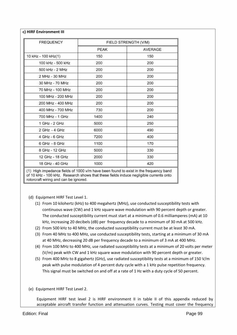
Edition: Final Page 99
c) HIRF Environment III
(d) Equipment HIRF Test Level 1.
(1) From 10 kilohertz (kHz) to 400 megahertz (MHz), use conducted susceptibility tests with
continuous wave (CW) and 1 kHz square wave modulation with 90 percent depth or greater.
The conducted susceptibility current must start at a minimum of 0.6 milliamperes (mA) at 10
kHz, increasing 20 decibels (dB) per frequency decade to a minimum of 30 mA at 500 kHz.
(2) From 500 kHz to 40 MHz, the conducted susceptibility current must be at least 30 mA.
(3) From 40 MHz to 400 MHz, use conducted susceptibility tests, starting at a minimum of 30 mA
at 40 MHz, decreasing 20 dB per frequency decade to a minimum of 3 mA at 400 MHz.
(4) From 100 MHz to 400 MHz, use radiated susceptibility tests at a minimum of 20 volts per meter
(V/m) peak with CW and 1 kHz square wave modulation with 90 percent depth or greater.
(5) From 400 MHz to 8 gigahertz (GHz), use radiated susceptibility tests at a minimum of 150 V/m
peak with pulse modulation of 4 percent duty cycle with a 1 kHz pulse repetition frequency.
This signal must be switched on and off at a rate of 1 Hz with a duty cycle of 50 percent.
(e) Equipment HIRF Test Level 2.
Equipment HIRF test level 2 is HIRF environment II in table II of this appendix reduced by acceptable aircraft transfer function and attenuation curves. Testing must cover the frequency

Edition: Final Page 100
band of 10 kHz to 8 GHz.
(f) Equipment HIRF Test Level 3.
(1) From 10 kHz to 400 MHz, use conducted susceptibility tests, starting at a minimum of 0.15 mA
at 10 kHz, increasing 20 dB per frequency decade to a minimum of 7.5 mA at 500 kHz.
(2) From 500 kHz to 40 MHz, use conducted susceptibility tests at a minimum of 7.5 mA.
(3) From 40 MHz to 400 MHz, use conducted susceptibility tests, starting at a minimum of 7.5 mA
at 40 MHz, decreasing 20 dB per frequency decade to a minimum of 0.75 mA at 400 MHz.
(4) From 100 MHz to 8 GHz, use radiated susceptibility tests at a minimum of 5 V/m.
APPENDIX E - MULTI ENGINE RPAS
RESERVED
APPENDIX F - SIMPLIFIED DESIGN LOAD CRITERIA FOR CONVENTIONAL RPA
F.1 General
(a) The design load criteria in this Appendix are an approved equivalent of those in CS-LUAS 321 to 455 of this document for the certification of conventional RPA as defined in CS-LUAS.1 and LUAS.301(d) and AMC LUAS.1.
(b) Unless otherwise stated, the nomenclature and symbols in this Appendix are the same as the corresponding nomenclature and symbols in CS-LUAS.
F.3 Special symbols
n1 = Aeroplane Positive Manoeuvring Limit Load Factor
n2 = Aeroplane Negative Manoeuvring Limit Load Factor
n3 = Aeroplane Positive Gust Limit Load Factor at VC
n4 = Aeroplane Negative Gust Limit Load Factor at VC
nflap = Aeroplane Positive Limit Load
Factor With Flaps Fully Extended at VF
*VFmin = Minimum Design Flap Speed = 4.98 √n1 W/S knots.
*VAmin = Minimum Design Manoeuvring Speed = 6.79 √n1 W/S knots.

Edition: Final Page 101
*VCmin = Minimum Design Cruising Speed = 7.69 √n1 W/S knots.
*VDmin = Minimum Design Dive Speed =
10.86 √n1 W/S knots.
*Also see sub-paragraph F.7(e)(2) of this Appendix.
(Speeds in knots, W in kg, S in m2.)
F.7 Flight loads
(a) Each flight load may be considered independent of altitude and, except for the local supporting structure for dead weight items, only the maximum design weight conditions must be investigated.
(b) Tables 1 and 3 and figure F3 of this Appendix must be used to determine values of n1, n2, n3 and n4, corresponding to the maximum design weights.
(c) Figures F1 and F2 of this Appendix must be used to determine values of n3 and n4 corresponding to the minimum flying weights, and, if these load factors
are greater than the load factors at the design weight, the supporting structure for dead weight items must be substantiated for the resulting higher load factors.
(d) Each specified wing and tail loading is independent of the centre of gravity range. However, a c.g. range, must be selected for the aeroplane and the basic fuslage structure must be investigated for the most adverse dead weight loading conditions for the c.g. range selected.
(e) The following loads and loading conditions are the minimums for which strength must be provided in the structure:
(1) Aeroplane equilibrium. The aerodynamic wing loads may be considered toact normal to the relative wind, and to have a magnitude of 1.05 times the aeroplane normal loads (as determined from sub-paragraph F.9 (b) and (c) of this Appendix) for the positive flight conditions and a magnitude equal to the aeroplane normal loads for the negative conditions. Each chordwise and normal component of this wing load must be considered.
(2) Minimum design airspeeds. The minimum design airspeeds may be chosen by the applicant except that they may not be less than the minimum speeds found by using Table 3 of this Appendix. In addition, VCmin need not exceed values of 0.9 VH actually obtained at sea level for the design weight. In computing these minimum design airspeeds, n1 may not be less than 3.8.
(3) Flight load factor. The limit flight load factors specified in Table 1 of this Appendix represent the ratio of the aerodynamic force component (acting normal to the assumed longitudinal axis of the aeroplane) to the weight of the aeroplane. A positive flight load factor is an aerodynamic force acting upward, with respect to the aeroplane.

Edition: Final Page 102
F.9 Flight conditions
(a) General. Each design condition in subparagraphs (b) and (c) of this paragraph must be used to assure sufficient strength for each condition of speed and load factor on or within the boundary of a V-n diagram for the aeroplane similar to the diagram in figure F3 of this Appendix. This diagram must also be used to determine the aeroplane structural operating limitations as specified in CS-LUAS 1501 (c) to 1513 and 1519.
(b) Symmetrical flight conditions. The RPA must be designed for symmetrical flight conditions as follows:
(1) The RPA must be designed for at least the four basic flight conditions, ‘A’, ‘D’, ‘E‘, and ‘G‘ as noted on the flight envelope of figure F3 of this Appendix. In addition, the following requirements apply:
(i) The design limit flight load factors corresponding to conditions ‘D’ and ‘E’ of figure F3 must be at least as great as those specified in Table 1 and figure F3 of this Appendix, and the design speed for these conditions must be at least equal to the value of VDmin found from Table 3 of this Appendix.
(ii) For conditions ‘A’ and ‘G‘ of figure F3, the load factors must correspond to those specified in Table 1 of this Appendix, and the design speeds must be computed using these load factors with the maximum static lift coefficient CNA determined by the applicant. However, in the absence of more precise computations, these latter conditions may be based on a value of
CNA = ±1.35 and the design speed for condition ‘A’ may be less than VAmin.
(iii) Conditions ‘C‘ and ‘F‘ of figure F3 need only be investigated when n3 W/S or n4 W/S are greater than
n1 W/S or n2 W/S of this Appendix, respectively.
(2) If flaps or other high lift devices intended for use at the relatively low airspeed of approach, landing, and take-off, are installed, the RPA must be designed for the two flight conditions corresponding to the values of limit flap-down factors specified in Table 1 of this Appendix with the flaps fully extended at not less than the design flap speed VFmin from Table 3 of this Appendix.
(c) Unsymmetrical flight conditions. Each affected structure must be designed for unsymmetrical loadings as follows:
(1) The aft fuselage-to-wing attachment must be designed for the critical vertical surface load determined in accordance with sub-paragraphs F.11 (c)(l) of this Appendix.
(2) The wing and wing carry-through structures must be designed for 100% of condition ‘A’ loading on one side of the plane of symmetry and 70% on the opposite side.
(3) The wing and wing carry-through structures must be designed for the loads resulting from a combination of 75% of the positive manoeuvring wing loading on both sides of the plane of symmetry and the maximum wing torsion resulting from aileron displacement. The effect of aileron displacement on wing torsion at VC or VA using the basic aerofoil moment coefficient, Cmo, modified over the aileron portion of the span, must be computed as follows:
(i) Cm = Cmo + 0.01 δu (up aileron side) wing basic aerofoil.
(ii) Cm = Cmo - 0.01 δd (down aileron side) wing basic aerofoil, where δu is the up aileron deflection and δd is the down aileron.

Edition: Final Page 103
(4) Δ critical, which is the sum of δu + δd, must be computed as follows:
(i) Compute Δa and Δb from the formulae –
where Δp = the maximum total deflection (sum of both aileron deflections) at VA with VA, VC, and VD described in sub-paragraph (2) of F.7(e) of this Appendix.
(ii) Compute K from the formula –
where δa is the down aileron deflection corresponding to Δa and δb is the down aileron deflection corresponding to Δb as computed in step (i).
(iii) If K is less than 1.0, Δa is Δ critical and must be used to determine δu, and δd. In this case, VC is the critical speed which must be used in computing the wing torsion loads over the aileronspan.
(iv) If K is equal to or greater than 1.0, Δb is Δ critical and must be used to determine δu and δd. In this case, VD is the critical speed which must be used in computing the wing torsion loads over the aileron span.
(d) Supplementary conditions; rear lift truss; engine torque; side load on engine mount.
Each of the following supplementary conditions must be investigated:
(1) In designing the rear lift truss, the special condition specified in CS-LUAS.369 may be investigated instead of condition ‘G’ of figure F3 of this Appendix.
(2) The engine mount and its supporting structure must be designed for the maximum limit torque corresponding to Maximum Expected Take-off Power or Thust and propeller speed acting simultaneously with the limit loads resulting from the maximum positive manoeuvring flight load factor n1. The limit torque must be obtained according to CS LUAS.361.
(3) The engine mount and its supporting structure must be designed for the loads resulting from a lateral limit load factor of not less than 1.47.

Edition: Final Page 104
F.11 Control surface loads
(a) General. Each control surface load must be determined using the criteria of sub-paragraph (b) of this paragraph and must lie within the simplified loadings of sub-paragraph (c) of this paragraph.
(b) Limit control system forces. In each control surface loading condition described in subparagraphs (c) to (e) of this paragraph, the airloads on the movable surfaces and the corresponding deflections need not exceed those which could be obtained in flight by employing the control system limit loads as defined in CS-LUAS.395(a)(1). If the surface loads are limited by these maximum control forces, the tabs must either be considered to be deflected to their maximum travel in the direction which would assist the pilot or the deflection must correspond to the maximum degree of ‘out of trim’ expected at the speed for the condition under consideration. The tab load, however, need not exceed the value specified in Table 2 of this Appendix.
(c) Surface loading conditions. Each surface loading condition must be investigated as follows:
(1) Simplified limit surface loadings and distributions for the horizontal tail, vertical tail, aileron, wing flaps, and trim tabs are specified in Table 2 and figures F4 and F5 of this Appendix. If more than one distribution is given, each distribution must be investigated.
F.13 Control system loads
(a) Primary flight controls and systems.
Each primary flight control and system must be designed as follows:
(1) The flight control system and its supporting structure must be designed for loads corresponding to 125% of the computed hinge moments of the movable control surface in the conditions prescribed in paragraph F.11 of this Appendix. In addition -
(i) The system limit loads need not exceed those that could be produced by the automatic devices operating the controls according to CS-LUAS.395(a)(1); and
(ii) The design must provide a rugged system for service use, including jamming, ground gusts, taxying downwind, control inertia, and friction.
(2) The limit control forces for elevator, aileron, and rudder controls, derived according to CS LUAS.395(a)(1), must be assumed to act at the appropriate control grips or pads as they would under flight conditions, and to be reacted at the attachments of the control system to the control surface horn.
(b) Reserved
(c) Reserved.
(d) Secondary controls and systems.
Secondary controls and systems must meet the requirements of CS-LUAS.405.

Edition: Final Page 105
Table 1 – Limit flight load factors
LIMIT FLIGHT LOAD FACTORS
Flaps
Up
n1 3.8
n2 –0·5 n1
n3 from Figure F1
n4 from Figure F2
Flaps
Down
nflap 0·5 n1
nflap Zero*
* Vertical wing load may be assumed equal to zero and only the flap part of the wing need be checked for this condition.

Edition: Final Page 106
Note: in Table 2, “Figure A4” must be intended as “Figure F4”; “Figure A5” as “Figure F4”; “A11(c)” as “F.11(c)”

Edition: Final Page 107
FIGURE F1
CHART FOR FINDING n3 FACTOR AT SPEED VC.

Edition: Final Page 108
FIGURE F2
CHART FOR FINDING n4 FACTOR AT SPEED VC.

Edition: Final Page 109
Note
1Conditions ‘C’ or ‘F’ need only be investigated when n3 W/s or n4 W/S is greater than n1 W/S or n2 W/S, respectively.
2. Condition ‘G’ need not be investigated when the supplementary condition specified in CS-LUAS.369 is investigated.

Edition: Final Page 110
FIGURE F3 – FLIGHT ENVELOPE
FIGURE F4
AVERAGE LIMIT CONTROL SURFACE LOADING

Edition: Final Page 111
FIGURE F5
AVERAGE LIMIT CONTROL SURFACE LOADING

Edition: Final Page 112
Note
1. Conditions ‘C’ or ‘F’ need only be investigated when n3 W/s or n4 W/S is greater than n1 W/S or n2 W/S, respectively.
2. Condition ‘G’ need not be investigated when the supplementary condition specified in CS-LUAS.369 is investigated.

Edition: Final Page 113
FIGURE F3 – FLIGHT ENVELOPE
FIGURE F4
AVERAGE LIMIT CONTROL SURFACE LOADING

Edition: Final Page 114
FIGURE F5
AVERAGE LIMIT CONTROL SURFACE LOADING
APPENDIX G - SIMPLIFIED CRITERIA FOR CONTROL SURFACE LOADINGS
G1 General
(a) If allowed by the specific requirements in this CS-LUAS, the values of control surface loading in this
Appendix may be used to determine the detailed rational requirements of CS-LUAS 395 to 459 unless the
Certification authority finds that these values result in unrealistic loads.

Edition: Final Page 115
(b) In the control surface loading conditions of paragraph G2, the airloads on the movable surfaces need
not exceed those that could be obtained in flight by using the maximum limit control forces derived
according to CS-LUAS.395(a)(1). If the surface loads are limited by these maximum limit pilot forces, the
tabs must be deflected -
(1) To their maximum travel in the direction that would assist the pilot; or
(2) In an amount corresponding to the greatest degree of out-of-trim expected at the speed for the
condition being considered.
(c) For a seaplane version of a landplane the landplane wing loadings may be used to determine the limit
manoeuvring control surface loadings (in accordance with paragraph G2 and figure G1 of this Appendix) if -
(1) The power of the seaplane engine does not exceed the power of the landplane engine;
(2) The placard manoeuvre speed of the seaplane does not exceed the placard manoeuvre speed of the
landplane;
(3) The maximum weight of the seaplane does not exceed the maximum weight of the landplane by more
than 10%;
(4) The landplane service experience does not show any serious control-surface load problem; and
(5) The landplane service experience is of sufficient scope to ascertain with reasonable accuracy that no
serious control surface load problem will develop on the seaplane.
G2 Control surface loads
Acceptable values of limit average manoeuvring control-surface loadings may be obtained from figure G1 of this Appendix in accordance with the following:
(a) For horizontal tail surfaces -
(1) With the conditions in CS-LUAS 423 (a)(i), obtain w as a function of W/S and surface deflection, using -
(i) Curve C of figure G1 for a deflection of 10° or less;
(ii) Curve B of figure G1 for a deflection of 20 °;
(iii) Curve A for a deflection of 30° or more;
(iv) Interpolation for all other deflections; and
(v) The distribution of figure G7; and
(2) With the conditions in CS- LUAS 423 (a)(2), obtain from curve B of figure G1 using the distribution of figure G7.
(b) For vertical tail surfaces -
(1) With the conditions in CS-LUAS.441 (a)(l), obtain w as a function of W/S and surface deflection using the same requirements as used in sub-paragraphs (a)( l)(i) to (a)( l)(v) of this paragraph; (2) With the

Edition: Final Page 116
conditions in CS-LUAS.441 (a)(2), obtain w from Curve C, using the distribution of figure G6; and
(3) With the conditions in CS-LUAS.441 (a)(3), obtain w from Curve A, using the distribution of figure G8.
(c) For ailerons, obtain w from Curve B, acting in both the up and down directions, using the distribution of figure G9.
FIGURE G1 – LIMIT AVERAGE MANOEUVRING CONTROL SURFACE LOADING
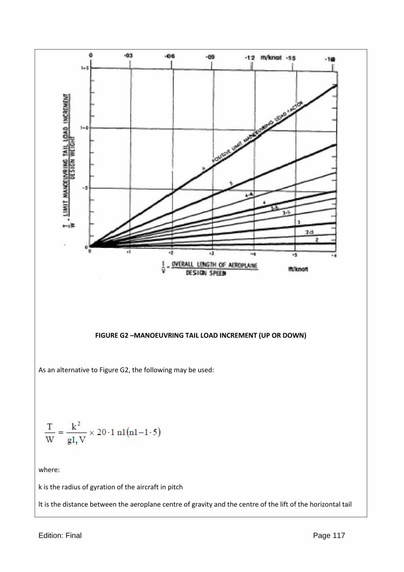
Edition: Final Page 117
FIGURE G2 –MANOEUVRING TAIL LOAD INCREMENT (UP OR DOWN)
As an alternative to Figure G2, the following may be used:
where:
k is the radius of gyration of the aircraft in pitch
lt is the distance between the aeroplane centre of gravity and the centre of the lift of the horizontal tail

Edition: Final Page 118
V is the aircraft speed in m/s.
FIGURE G3
UP AND DOWN GUST LOADING ON HORIZONTALTAIL SURFACE
FIGURE G4 – RESERVED

Edition: Final Page 119
FIGURE G5 - GUST LOADING ON VERTICAL TAL SURFACE
FIGURE G6 -TAIL SURFACE LOAD DISTRIBUTION
NOTES:
(a) In balancing conditions in CS-LUAS.421, P = 40% of net balancing load (flaps retracted); and P = 0 (flaps deflected).
(b) In the condition in CS-LUAS.441 (a)(2), P = 20% of net tail load.
(c) The load on the fixed surface must be -

Edition: Final Page 120
(1) 140% of the net balancing load for the flaps retracted case of note (a);
(2) 100% of the net balancing load for the flaps deflected case of note (a); and
(3) 120% of the net balancing load for the case in note (b)
FIGURE G7
TAIL SURFACE LOAD DISTRIBUTION
FIGURE G8
TAIL SURFACE LOAD DISTRIBUTION

Edition: Final Page 121
FIGURE G9
AILERON LOAD DISTRIBUTION
APPENDIX H - LANDING GEAR
H.1 General
The Appendix H applies to conventional wheeled landing gears arrangements. If this Appendix is applied the requirements of this Appendix must be selected following the criteria established therein.
H.2 Ground load conditions and assumptions
(a) Reserved
(b) The selected limit vertical inertia load factor at the centre of gravity of the RPA for the ground load conditions prescribed in this Appendix may not be less than that which would be obtained when landing with a descent velocity (V), in metres per second, equal to 0·51 (Mg/S)1/4 except that this velocity need not be more than 3·05 m/s and may not be less than 2·13 m/s.
(c) Wing lift not exceeding two-thirds of the weight of the aeroplane may be assumed to exist throughout the landing impact and to act through the centre of gravity. The ground reaction load factor may be equal to the inertia load factor minus the ratio of the above assumed wing lift to the RPA weight.
(d) If energy absorption tests are made to determine the limit load factor corresponding to the required limit descent velocities, these tests must be made under H.5.
(e) No inertia load factor used for design purposes may be less than 2·67, nor may the limit ground

Edition: Final Page 122
reaction load factor be less than 2·00 at design maximum weight, unless these lower values will not be exceeded in taxying at speeds up to take-off speed over terrain as rough as that expected in service.
H.3 Landing gear arrangement
Paragraphs H.4 to H.6, or the conditions in H.16, apply to RPA with conventional arrangements of main and nose gear, or main and tail gear.
H.4 Level landing conditions
(a) For a level landing, the RPA is assumed to be in the following attitudes:
(1) For RPA with tail wheels, a normal level flight attitude.
(2) For RPA with nose wheels, attitudes in which –
(i) The nose and main wheels contact the ground simultaneously; and
(ii) The main wheels contact the ground and the nose wheel is just clear of the ground.
The attitude used in sub-paragraph (a)(2)(i) of this paragraph may be used in the analysis required under sub-paragraph (a)(2)(ii) of this paragraph.
(b) A drag component of not less than 25% of the maximum vertical ground reactions (neglecting wing lift) must be properly combined with the vertical reactions. (See AMC H.4(b) )
H.5 Tail-down landing conditions
(a) For a tail-down landing, the RPA is assumed to be in the following attitudes:
(1) For RPA with tail wheels, an attitude in which the main and tail wheels contact the ground simultaneously.
(2) For RPA with nose wheels, a stalling attitude, or the maximum angle allowing ground clearance by each part of the RPA, whichever is less.
(b) For RPA with either tail or nose wheels, ground reactions are assumed to be vertical, with the wheels up to speed before the maximum vertical load is attained.
H.6 One-wheel landing conditions
For the one-wheel landing condition, the RPA is assumed to be in the level attitude and to contact the ground on one side of the main landing gear. In this attitude, the ground reactions must be the same as those obtained on that side under H.4.
H.7 Side load conditions
(a) For the side load condition, the RPA is assumed to be in a level attitude with only the main wheels contacting the ground and with the shock absorbers and tyres in their static positions.
(b) The limit vertical load factor must be 1·33, with the vertical ground reaction divided equally between the main wheels.
(c) The limit side inertia factor must be 0·83, with the side ground reaction divided

Edition: Final Page 123
between the main wheels so that –
(1) 0·5 (Mg) is acting inboard on one side; and
(2) 0·33 (Mg) is acting outboard on the other side.
H.8 Braked roll conditions
Under braked roll conditions, with the shock absorbers and tyres in their static positions, the following apply:
(a) The limit vertical load factor must be 1·33.
(b) The attitudes and ground contacts must be those described in H.4 for level landings.
(c) A drag reaction equal to the vertical reaction at the wheel multiplied by a coefficient of friction of 0·8 must be applied at the ground contact point of each wheel with brakes, except that the drag reaction need not exceed the maximum value based on limiting brake torque.
H.9 Supplementary conditions for tail wheels
In determining the ground loads on the tail wheel and affected supporting structures, the following apply:
(a) For the obstruction load, the limit ground reaction obtained in the tail down landing condition is assumed to act up and aft through the axle at 45°. The shock absorber and tyre may be assumed to be in their static positions.
(b) For the side load, a limit vertical ground reaction equal to the static load on the tail wheel, in combination with a side component of equal magnitude, is assumed. In addition
(1) If a swivel is used, the tail wheel is assumed to be swivelled 90° to the aeroplane longitudinal axis with the resu tant ground load passing through the axle;
(2) If a lock, steering device, or shimmy damper is used, the tail wheel is also assumed to be in the trailing position with the side load acting at the ground contact point; and
(3) The shock absorber and tyre are assumed to be in their static positions.
H.10 Supplementary conditions for nose wheels
In determining the ground loads on nose wheels and affected supporting structures, and assuming that the shock absorbers and tyres are in their static positions, the following conditions must be met:
(a) For aft loads, the limit force components at the axle must be –
(1) A vertical component of 2·25 times the static load on the wheel; and
(2) A drag component of 0·8 times the vertical load.
(b) For forward loads, the limit force components at ground contact must be –
(1) A vertical component of 2·25 times the static load on the wheel; and
(2) A forward component of 0·4 times the vertical load.
(c) For side loads, the limit force components at the axle must be –
(1) A vertical component of 2·25 times the static load on the wheel; and
(2) A side component of 0·7 times the vertical load.

Edition: Final Page 124
H.11 Supplementary conditions for ski-RPA
In determining ground loads for ski-RPA and assuming that the RPA is resting on the ground with one main ski frozen at rest and the other skis free to slide, a limit side force equal to 0·036 times the design maximum weight must be applied near the tail assembly, with a factor of safety of 1.
H.12 Shock absorption tests
(a) It must be shown that the limit load factors selected for design in accordance with H.2 will not be eceeded. This must be shown by energy absorption tests except that analysis may be used for
(1) Increases in previously approved take-off and landing weights,
(2) Landing gears previously approved wheel type RPA with similar weights and performances
(3) Landing gears using a steel or composite material spring or any other energy absorption element where the shock
absorption characteristics are not essentially affected by the rate of compression or tension,
(4) Landing gears for which adequate experience and substantiating data are available.
(b) The landing gear may not fail, but may yield, in a test showing its reserved energy absorption capacity, simulating a descent velocity of 1·2 times the limit descent velocity, assuming wing lift equal to the weight of the RPA. The test may be replaced by an analysis in the same cases as sub-paragraphs (a)(1) to (a)(4) of this paragraph.
H.13 Limit drop tests
(a) If compliance with H.12(a) is shown by free drop tests, these tests must be made on the complete RPA, or on units consisting of wheel, tyre, and shock absorber, in their proper relation, from free drop heights not less than those determined by the following formula:
h=0.0132(Mg/S)1/2
However, the free drop height may not be less than 0·235 m and need not be more than 0·475 m.
(b) If the effect of wing lift is provided for in free drop tests, the landing gear must be dropped with an effective weight equal to –
where –
Me= the effective weight to be used in the drop test (kg);
h = specified free drop height (m);
d = deflection under impact of the tyre (at the approved inflation pressure) plus the vertical component of the axle travel relative to the drop mass (m);
M = MM for main gear units (kg), equal to the static weight on that unit with the RPA in the level attitude (with the nose wheel clear in the case of nose wheel type aeroplanes);
M = MT for tail gear units (kg), equal to the static weight on the tail unit with the RPA in the tail down attitude;
M = MN for nose wheel units (kg), equal to the vertical component of the static reaction that would exist at the nose wheel, assuming that the mass of the RPA acts at the centre of gravity and exerts a force of 1·0 g

Edition: Final Page 125
downward and 0·33 g forward;
L = the ratio of the assumed wing lift to the RPA weight, but not more than 0·667; and
g = the acceleration due to gravity (m/s2).
(c) The limit inertia load factor must be determined in a rational or conservative manner, during the drop test, using a landing gear unit attitude, and applied drag loads, that represent the landing conditions.
(d) The value of d used in the computation of Me in sub-paragraph (b) of this paragraph may not exceed the value actually obtained in the drop test.
(e) The limit inertia load factor must be determined from the drop test in sub-paragraph (b) of this paragraph according to the following formula:
where –
nj = the load factor developed in the drop test (that is, the acceleration (dv/dt) in g recorded in the drop test) plus 1·0; and
Me, M and L are the same as in the drop test computation.
(f) The value of n determined in accordance with sub-paragraph (e) of this paragraph may not
be more than the limit inertia load factor used in the landing conditions in H.2.
H.14 Ground load dynamic tests
(a) If compliance with the ground load requirements of H.4 to H.6 is shown dynamically by drop test, one drop test must be conducted that meets H.13 except that the drop height must be –
(1) 2·25 times the drop height prescribed in H.13(a); or
(2) Sufficient to develop 1·5 times the limit load factor.
(b) The critical landing condition for each of the design conditions specified in H.4 to H.6 must be used for proof of strength.
H.15 Reserve energy absorption
(a) If compliance with the reserve energy absorption requirement in H.12 (b) is shown by free drop tests, the drop height may not be less than 1·44 times that specified in H.13.
(b) If the effect of wing lift is provided for, the unit must be dropped with an effective mass equal to
when the symbols and other details are the same as H.13.

Edition: Final Page 126

Edition: Final Page 127
2.2 BOOK 2 – ACCEPTABLE MEANS OF COMPLIANCE
SUBPART A - GENERAL
AMC-LUAS.1 Applicability a) The extent of the applicability of the CS-LUAS Requirements shall be agreed with the certifying
authority based on the Specific Operational Risk Assessment (SORA, JARUS WG-6 document, latest revision) as a Total Hazard and Risk Assessment performed by the applicant. The concept of CS-LUAS is based on the possibility of an operational limited type certificate. The certification basis should be agreed between the applicant and the authority depending on the risk of the operations. The approved operations and the agreed certification basis will be specified in the type certificate. For operations which are of no risk to third parties the following requirements constitute the minimum certification basis:
1) 1309, Equipment, systems, and installations 2) 1412, Emergency Recovery Capability 3) 1413, Contingency Procedures
Additional requirements may be applicable for compliance demonstration to the above requirements. The intent of this minimum set of requirements is to ensure the RPA operation remains of no risk to third parties. For any operation outside that which is specified in the type certificate, a re-evaluation of the certification basis will be required.. Parts of this airworthiness code may be applied in the specific category, where the traditional approach to aircraft certification (approving the design, issuing an airworthiness approval and type certificate) may not be appropriate.
b) Conventional Design definitions
1. Conventional design in Subpart B, Flight. A conventional RPAS is required to have a natural stability in the longitudinal and lateral-direction motion.
For this RPAS, for compliance demonstration to subpart B, alternative requirements, agreed by the authority can be applied (e.g. CS-VLA where appropriate)
2. Conventional design in Subpart C, Structures. (a) A conventional configuration of a RPA where simplified design criteria for subpart C could be applied is defined as:
(1) A single engine excluding turbine powerplants;
(2) A main wing located closer to the aeroplane’s centre of gravity than to the aft, fuselage-mounted, empennage;
(3) A main wing that contains a quarterchord sweep angle of not more than 15 degrees fore or aft;
(4) A main wing that is equipped with trailing-edge controls (ailerons or flaps, or both);
(5) A main wing aspect ratio not greater than 7;
(6) A horizontal tail aspect ratio not greater than 4;

Edition: Final Page 128
(7) A horizontal tail volume coefficient not less than 0.34;
(8) A vertical tail aspect ratio not greater than 2;
(9) A vertical tail platform area not greater than 10 percent of the wing platform area; and
(10) Symmetrical airfoils must be used in both the horizontal and vertical tail designs.
(11) Lifting surfaces are either untapered or have essentially continuous taper.
(b) A RPA that contains anyone of the below listed design features cannot be considered as conventional and therefore the simplified criteria cannot be used.
(1) Canard, tandem-wing, close-coupled, or tailless arrangements of the lifting surfaces;
(2) Biplane or multiplane wing arrangements;
(3) T-tail, V-tail, or cruciform-tail (+) arrangements;
(4) Highly-swept wing platform (more than 15-degrees of sweep at the quarter-chord), delta planforms, or slatted lifting surfaces; or
(5) Winglets or other wing tip devices, or outboard fins.
(c) The simplified design criteria for conventional RPA according to (a) are described in Appendix F of CS-LUAS and can be used under the conditions of CS-LUAS.301(d).
(d) Other simplified criteria for conventional RPA according to (a) are described in Appendix G and can be used under the conditions of CS-LUAS.391(b). See also AMC LUAS.391(b)
3. Conventional design in Subpart D, Design and Construction. Reserved for CS-UAS
AMC LUAS.21 Proof of compliance
(a) The following general tolerances are allowed during flight testing. However, greater tolerances may be allowed in particular tests.
Item Tolerance
Weight +5%,-10%
Critical items affected by weight +5%, -1%
C.G. ±7%total travel
(b) Substantiation of the data and characteristics to be determined according to this subpart may not require exceptional piloting skill, alertness or exceptionally favourable conditions.
(c) Consideration must be given to significant variations of performance and in flight characteristics caused by rain and the accumulation of insects.
AMC-LUAS. 23 Approved Operational Envelope
A safe flight is a flight where the probability of one or more fatalities on ground or in the air is below a societal agreed level.
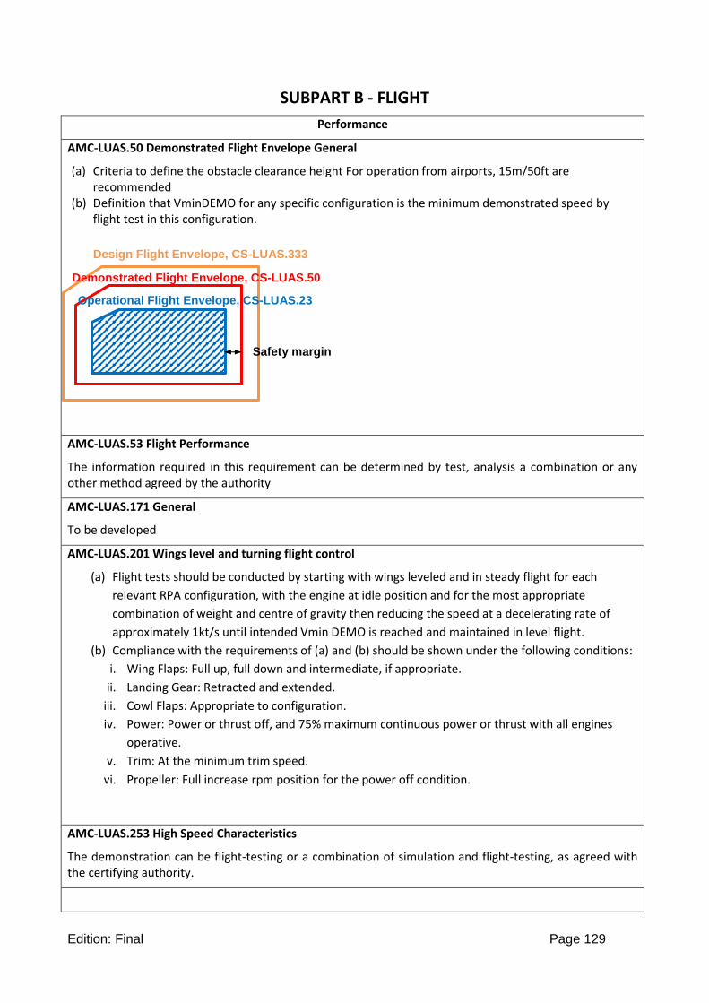
Edition: Final Page 129
SUBPART B - FLIGHT
Performance
AMC-LUAS.50 Demonstrated Flight Envelope General
(a) Criteria to define the obstacle clearance height For operation from airports, 15m/50ft are recommended
(b) Definition that VminDEMO for any specific configuration is the minimum demonstrated speed by flight test in this configuration.
AMC-LUAS.53 Flight Performance
The information required in this requirement can be determined by test, analysis a combination or any other method agreed by the authority
AMC-LUAS.171 General
To be developed
AMC-LUAS.201 Wings level and turning flight control
(a) Flight tests should be conducted by starting with wings leveled and in steady flight for each
relevant RPA configuration, with the engine at idle position and for the most appropriate
combination of weight and centre of gravity then reducing the speed at a decelerating rate of
approximately 1kt/s until intended Vmin DEMO is reached and maintained in level flight.
(b) Compliance with the requirements of (a) and (b) should be shown under the following conditions:
i. Wing Flaps: Full up, full down and intermediate, if appropriate.
ii. Landing Gear: Retracted and extended.
iii. Cowl Flaps: Appropriate to configuration.
iv. Power: Power or thrust off, and 75% maximum continuous power or thrust with all engines
operative.
v. Trim: At the minimum trim speed.
vi. Propeller: Full increase rpm position for the power off condition.
AMC-LUAS.253 High Speed Characteristics
The demonstration can be flight-testing or a combination of simulation and flight-testing, as agreed with the certifying authority.
Design Flight Envelope, CS-LUAS.333
Demonstrated Flight Envelope, CS-LUAS.50
Operational Flight Envelope, CS-LUAS.23
Safety margin

Edition: Final Page 130
AMC-LUAS.283 Launch safety area
Ballistic footprint, rocket misalignment errors, poor catapult launch performance, poor engine performance, flight control failures, etc., should be considered as part of the hazard analysis to determine the launch safety area.
SUBPART C - STRUCTURE
AMC-LUAS.307 Proof of structure
To be developed
AMC LUAS.321(c)
Flight loads – General
For aeroplanes with an Md less than 0.5 the effects of compressibility are unlikely to be significant.

Edition: Final Page 131
AMC LUAS.341 Gust Load Factors
In the absence of a more rational analysis the gust load factors must be computed as follows:
Where-
Ude = Derived gust velocities referred to in CS LUAS.333 (c) (m/s);
ρo = Density of air at sea-level (kg/m3)
ρ = Density of air (kg/m3) at the altitude considered;
W/S = Wing loading due to the applicable weight of the aeroplane in the particular load case (N/m2);
C = Mean geometric chord (m);
g = Acceleration due to gravity (m/sec2);
V = Aeroplane equivalent speed (m/s);
and
a = Slope of the aeroplane normal force coefficient curve CNA per radian if the gust loads are applied to the wings and horizontal tail surfaces simultaneously by a rational method. The wing lift curve slope CL per radian may be used when the gust load is applied to the wings only and the horizontal tail gust loads are treated as a separate condition.
The above formulae may be used for canard or tandem wing configurations, provided it results in conservative net loads with respect to the gust criteria of CS LUAS.333(c), or a gust alleviation factor of Kg = 1.2 is used.
NOTE:
The derivation of the above formulae is explained in the document ESDU 04024, An introduction to rigid aeroplane response to gusts and atmospheric turbulence.
AMC LUAS.343(b)
Design fuel loads
Fuel carried in the wing increases the inertia relief on the wing structure during manoeuvres and gusts which results in lower stresses and deflections. However, if the wing fuel tanks are empty the inertia load of the wing is reduced which, depending on the particular design, may lead to an increase of the bending stresses in the wing structure itself and in the wing attachments. In order not to over stress the aeroplane's structure the maximum weight of the aeroplane without any fuel in the wing tanks should therefore be established, taking into account the applicable manoeuvre and gust loadings.
AMC LUAS.345(d)
High lift devices
The effect of propeller slipstream on the extended flaps may be limited to the flap area behind the

Edition: Final Page 132
propeller circle area.
AMC LUAS.371 and 371(a) Gyroscopic and aerodynamic loads
1. Method of evaluation of gyroscopic loads For a two-bladed propeller the maximum gyroscopic couple (in Nm) is given by 2Ip 1 2. For three or
more evenly spaced blades the gyroscopic couple is Ip 1 2, where:-
Ip (kg m2) is the polar moment of inertia of the propeller
1 (radians/second) is the propeller rotation, and
2 (radians/second) is the rate of pitch or yaw.
2. Gyroscopic and aerodynamic loads The aerodynamic loads specified in CS LUAS.371 include asymmetric flow through the propeller disc. Experience has shown that the effects of this asymmetric flow on the engine mount and its supporting structure are relatively small and may be discounted, if propellers are installed having diameters of 2.74 m (nine feet) or less.
AMC LUAS.391(b)
Control surface loads
1. According to CS-LUAS.391(b) Appendix G can be used only when:
1) the RPA is conventional as per AMC LUAS.1, and 2) the conditions of CS LUAS.391(b) from (i) to (iv) are verified, and 3) The use of Appendix G is explicitly allowed by the specific CS-LUAS paragraph.
2. With reference to CS-LUAS.391(b)(i) the “high performance” criteria should be agreed with the Authority.
AMC LUAS.393(a)
Loads parallel to hinge lines
On primary control surfaces and other movable surfaces, such as speedbrakes, flaps (in retracted position) and all-moving tailplanes the loads acting parallel to the hinge line should take into account the effect of wear and axial play between the surface and its supporting structure. Compliance may be shown by analysis or by test.
AMC 23.393(b)
Loads parallel to hinge lines
For control surfaces of a wing or horizontal tail with a high dihedral angle and of a V-tail configuration
the K-factor may be calculated as follows:

Edition: Final Page 133
where : = dihedral angle measured to the horizontal plane
As a simplification the following K-factors may be assumed:
for dihedral angles up to ±10° K = 12
and for dihedral angles between 80° and 90° K = 24
AMC CS LUAS.425 Vertical gust loads
In the absence of a more rational analysis, the incremental load due to the gust may be computed as follows only on aeroplane configurations with aft-mounted, horizontal surfaces, unless its use elsewhere is shown to be conservative:
where –
ΔLht = Incremental horizontal tail load (N);
ρo = Density of air at sea-level (kg/m3)
Kg = Gust alleviation factor defined in CS LUAS.341;
Ude = Derived gust velocity (m/s);
V = RPA equivalent speed (m/s);
aht = Slope of aft horizontal tail lift curve (per radian);
Sht = Area of aft horizontal tail (m2); and
(1-d/d) = Downwash factor.
AMC LUAS.441
Manoeuvring Loads (Interpretative Material and Acceptable Means of Compliance)
For RPAs where the horizontal tail is supported by the vertical tail, the tail surfaces and their supporting structure including the rear portion of the fuselage should be d signed to withstand the prescribed loadings on the vertical tail and the roll-moments induced by the horizontal tail acting in the same direction.
For T-tails in the absence of a more rational analysis, the rolling moment induced by deflection of the vertical rudder may be computed as follows:

Edition: Final Page 134
AMC LUAS.443
Lateral gust loads
1. For RPAs where the horizontal tail is supported by the vertical tail, the tail surfaces and their supporting
structure including the rear portion of the fuselage should be designed to withstand the prescribed loading
on the vertical tail and the rolling moment induced by the horizontal tail acting in the same direction.
For T-tails, in the absence of a more rational analysis, the rolling moment induced by gust load may be
computed as follows:
where:
Mr = induced rolling moment at horizontal tail
Sh = area of horizontal tail
Bh = span of horizontal tail
U = gust velocity (m/s) as specified in CS LUAS.333(c)
Kgt = gust alleviation factor of vertical tail as specified in CS LUAS.443(c)
In computing ‘Sh’ and ‘bh’ the horizontal tail root has to be assumed on a vertical plane through the centreline of the aeroplane fuselage.

Edition: Final Page 135
AMC LUAS.535
Parachute thrust off landing conditions
1. The requirement considers parachute landing conditions with thrust off. Parachute landing conditions with thrust should be addressed by special condition.
2. Subpara LUAS.535(b) requires a drop test to derived the vertical limit load factor. The drop height Hd
to be used in the drop test can be derived, from energetic considerations, by the following formula:
Hd =Vi
2
2g
where –
Vi = vertical velocity of the RPA at impact with ground (“contact velocity” or “sinking speed”),
g = gravity acceleration.
The vertical impact velocity Vi to be used in the formula must be the most likely vertical impact velocity that the RPA can reach during normal landing operations with the parachute system functioning as intended. The Vi can be determined either by test or derived by a rational analysis as a function of the parachute system characteristics and mode of operation. If the parachute deployment height is sufficient, and the RPA is able to reach its limit vertical velocity before impacting the ground, the following formula

Edition: Final Page 136
can be used for the impact vertical velocity:
Vlim = √2gM
ρScD
where –
g = gravity acceleration;
M = maximum design landing mass of the RPA;
S = minimum cross sectional area of the RPA in the landing configuration with the parachute fully deployed;
= density of the air;
cD = minimum RPA aerodynamic drag coefficient in the landing configuration with the parachute fully deployed.
3. Subparagraph LUAS.535(c). The landing conditions must be derived in the actual RPA landing configuration with the parachute deployed. E.g. there could be an inverted RPA configuration where the RPA must turn upside-down beneath a parachute before landing in order to better protect the payload or the systems during the impact at ground; in this case this particular configuration must be taken into consideration in deriving the ground load conditions. For skid RPA the conditions of CS-LUAS.539 apply; in this case an horizontal component of the velocity at the contact point with ground must be considered in principle due to possible wind drift effect.
AMC LUAS.539
Skid landing condition
The requirement assumes the RPA has a skid landing gear with two skids only. More than two skids should
be deal with a special condition.
AMC LUAS.561 (b) and (c)
Crashworthiness
1. Explanation
a. The intent of Subparagraph CS-LUAS.561(b) is to protect third parties on the ground, outside
the forced landing area selected under CS-LUAS.1412(a)(2), when such an area is chosen for
assuring the emergency recovery capability of the RPARPA required by CS-LUAS.1412(a). In
this case Subparagraph (b) requires that Subparagraph (c) be verified.
b. Subparagraph CS-LUAS.561(c) requires design features that aim to protect third parties on the
ground, in case of a forced landing, from projection of parts and fire/explosion hazards.
c. Self-containment features must be included in the RPA design as much as practical, in order to
minimise the risk that some dangerous parts such as high speed rotating masses (e.g.

Edition: Final Page 137
propellers, engines and other moving parts) come loose after a forced landing and are not
contained inside the RPA.
d. Subparagraph 561(c)(1) refers to those dangerous parts that could detach or break and that
could be projected away from the RPA outside the forced landing area. Items of mass to be
considered include, but are not limited to, propellers, engines, payloads along with their
components and breakable parts. The probability that these parts or pieces travel outside the
forced landing area should be minimised.
e. Subparagraph 561(c)(2) requires that the RPA does not constitute a source of ignition or leak
of flammable fluids in hazardous quantities, in order to protect third parties on the ground,
from fire hazard.
f. Subparagraph 561(c)(3) aims to protect third parties outside the forced landing area from the
adverse effects of a possible explosion after the forced landing or impact with the ground.
g. While specific design features in conjunction with structural analysis can be developed for
complying with Subparagraphs 561(c)(2) (ref. Para. 2.3 of this AMC), in order to comply with
Subparagraphs 561(c)(1) and (c)(3) design features such as self-containment features could be
not enough. As a matter of fact even if self containment features could be effective in avoiding
the projection of small fragmented pieces, they could be not effective for avoiding the
projection of large and relatively heavy parts such as propeller blades, or for avoiding
explosion at the time or immediately after an impact with the ground. Therefore, in these
cases a forced landing area should be defined in order to protect third parties on the ground
from projection of dangerous non containable parts and from the effect of possible post
landing/impact explosions.
2. Procedure
2.1 Engineering judgement, also based on service experience, should be exercised in order to
identify effective self-containment design features for compliance with Subparagraph LUAS.561(c).
This should be done by a documented design review.
2.2 LUAS.561(c)(1) and (c)(3). Forced landing area.
a. Subparagraph LUAS.561(c)(1) requires that the projection of parts that may constitute a
potential injury to third parties outside the forced landing area is unlikely and
Subparagraph LUAS 561(c)(3) requires that third parties outside the forced landing area
must be protected against the effect of a post landing or impact explosion.
b. The size of the forced landing area should be established by analysis, including simulation,

Edition: Final Page 138
and/or test and well documented. The method for determining the size and shape of the
forced landing area should be agreed with the Authority in order to comply with ICAO
requirements on equivalent levels of safety as manned aviation (Ref. ICAO Circular 328).
c. A circular forced landing area could be derived based on the following two cases,
depending on whether it is likely or not to have dangerous fragments or parts projected
away from the RPA as a consequence of the emergency forced landing or impact with the
ground. The evaluation whether a fragment or a part could be dangerous for third parties
should be done on the basis of two parameter, i.e. the ballistic coefficient of the fragment
or part (the ballistic coefficient is the ratio between the fragment or part weight and its
reference surface) and its kinetic energy. If the fragment or part has a low ballistic
coefficient (i.e. it is a small light piece) and has a low kinetic energy, less than or equal to
66 J, then the fragment or part is not potentially dangerous and it has not to be considered
as a dangerous projected part in the calculation of the forced landing area.
(1) Case 1. It is likely to have dangerous fragments or parts projected as a consequence of
the forced landing or impact with the ground. In this case the forced landing (circular)
area should be calculated as the circular area whose radius Rrec is the greater of the
maximum range travelled by the part, taking into account any possible slide and
rebound and simulation scatter (Rsim) and the radius of the circular lethal area due to
a post landing or impact explosion (D), if there is such risk.
Rrec = max {Rsim, D}
Rsim is the maximum range travelled by the projected part, taking into account any
possible slide and rebound, multiplied by a safety factor that takes account of the
simulation scatter and approximations. A possible step-by-step methodology for
calculating the radius Rsim is described at point 2.2.d of this AMC.
D is the radius of the circular lethal area due to explosion, such that 100% of the
population inside is expected to have an injury due to the explosion. The radius D can
be determined by the following formula:
D = K ∙ (WTNT)1 3⁄
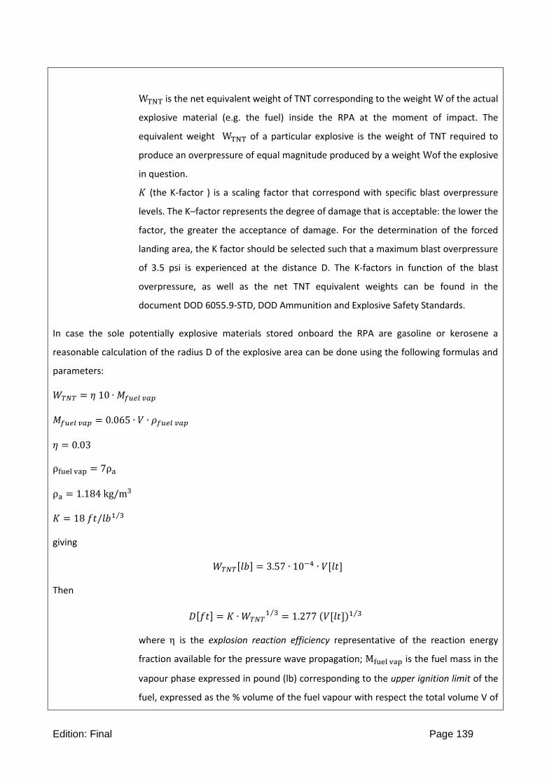
Edition: Final Page 139
WTNT is the net equivalent weight of TNT corresponding to the weight W of the actual
explosive material (e.g. the fuel) inside the RPA at the moment of impact. The
equivalent weight WTNT of a particular explosive is the weight of TNT required to
produce an overpressure of equal magnitude produced by a weight Wof the explosive
in question.
𝐾 (the K-factor ) is a scaling factor that correspond with specific blast overpressure
levels. The K–factor represents the degree of damage that is acceptable: the lower the
factor, the greater the acceptance of damage. For the determination of the forced
landing area, the K factor should be selected such that a maximum blast overpressure
of 3.5 psi is experienced at the distance D. The K-factors in function of the blast
overpressure, as well as the net TNT equivalent weights can be found in the
document DOD 6055.9-STD, DOD Ammunition and Explosive Safety Standards.
In case the sole potentially explosive materials stored onboard the RPA are gasoline or kerosene a
reasonable calculation of the radius D of the explosive area can be done using the following formulas and
parameters:
𝑊𝑇𝑁𝑇 = 𝜂 10 ∙ 𝑀𝑓𝑢𝑒𝑙 𝑣𝑎𝑝
𝑀𝑓𝑢𝑒𝑙 𝑣𝑎𝑝 = 0.065 ∙ 𝑉 ∙ 𝜌𝑓𝑢𝑒𝑙 𝑣𝑎𝑝
𝜂 = 0.03
ρfuel vap = 7ρa
ρa = 1.184 kg/m3
𝐾 = 18 𝑓𝑡/𝑙𝑏1 3⁄
giving
𝑊𝑇𝑁𝑇[𝑙𝑏] = 3.57 ∙ 10−4 ∙ 𝑉[𝑙𝑡]
Then
𝐷[𝑓𝑡] = 𝐾 ∙ 𝑊𝑇𝑁𝑇1 3⁄ = 1.277 (𝑉[𝑙𝑡])1 3⁄
where η is the explosion reaction efficiency representative of the reaction energy
fraction available for the pressure wave propagation; Mfuel vap is the fuel mass in the
vapour phase expressed in pound (lb) corresponding to the upper ignition limit of the
fuel, expressed as the % volume of the fuel vapour with respect the total volume V of

Edition: Final Page 140
the RPA tanks(s), including the tank volume occupied by the liquid fuel; ρfuel vap is the
fuel vapor density. At ambient temperature and humidity conditions, the gasoline
vapor density is 3.5 times the density of the air, whereas the kerosene vapor density,
which is conservatively assumed here as ρfuel vap , is 7 times the density of the air;
ρa = 1.184 kg/m3 is the air density in standard ambient conditions ( 25°C, 1 atm).
The selected value of the factor K takes into account a max. blast overpressure of 3.5
psi bearable by the 99% of the exposed unprotected population without any injuries
(typically at the hear-drum).
(2) Case 2. It is not likely to have dangerous fragments or parts projected as a
consequence of the forced landing or impact with the ground. In this case no
dangerous fragments or parts are expected to separate from the RPA and travel
outside the recovery area as a consequence of the emergency forced landing or
impact with ground, therefore the forced landing area could be calculated by taking
account of the impact of the RPA, without any separation of parts, in conjunction with
a possible post landing explosion. The radius Rrec of the circular forced landing area
can then be obtained from the following formula:
where:
rp is the radius of a person (rp = 1 ft is acceptable),
hp is the height of a person (hp= 6 ft is acceptable),
γ is the impact (flight path) angle equal to the angle between the landing or impact surface and
the impact velocity vector of the RPA.
D = K ∙ (WTNT)1 3⁄ is the radius of the circular lethal area due to explosion.
d. A deterministic analytical approach to determine a circular forced landing area due to the
projection of fragments or parts should encompass at least the following steps:
(1) Determine the most critical realistic forced landing or crash scenario in
order to:
(i) Estimate the mass, the trajectory, the velocity, the impact energy

Edition: Final Page 141
and the attitude of the RPA at the moment of landing or impact
with the ground;
(ii) Determine the parts of the RPA that are likely to impact the
ground and that could brake loose as a consequence of the
impact;
(iii) Estimate the maximum ground accelerations the RPA and its
parts could be subjected to during the forced landing in order to
evaluate the capability of the structure to withstand those
accelerations. The estimated ground loads may be considered as
ultimate loads. For example, if the RPA supporting structure is
designed to withstand a certain level of ultimate inertia loads
and, during the forced landing, such level is exceeded in some
element or part of the structure, then this element or part is
likely to break loose and detach during the forced landing;
therefore its subsequent trajectory should be taken into account
in the calculation of the radius of the forced landing area as
described in the following steps;
(2) Estimate the mass, the shape and, if necessary, the stiffness of the
projected parts;
(3) Estimate the initial position and attitude and the initial velocity vector
(intensity and direction) of the projected parts immediately after their
detachment;
(4) Calculate the trajectory of the projected parts taking into account in a
rational or conservative manner all the significant external forces acting
on them including weight, aerodynamic forces with drag and friction with
ground;
(5) Determine the distance (range) travelled by the projected parts taking
account of any possible rebound;
(6) Variate the significant parameters and initial conditions (mass, velocity
vector, stiffness, shape, initial position and attitude, coefficient of friction,
etc.) of the projected parts in order to carry out a parametrical/sensitivity
study of the trajectories and determine the maximum range covered by
the projected parts.
Determine the radius Rsim of the forced landing area due to projection of parts as not less than 1.2 times

Edition: Final Page 142
the maximum range determined at point d.(6) e. In case an explosion is expected as a consequence of a
forced landing , the minimum distance of any building from the centre of the forced landing area should
be calculated as the radius D of the circular lethal area due to explosion done by the formula used for Case
1 at para. 2.2(c)(1), with a K-factor corresponding to a blast overpressure of 0.5 psi.
2.3 LUAS.561(c)(2). Fire hazard.
a. An RPA design assessment should be carried out and documented in order to identify
design solutions that could prevent post landing/crash fire or explosion ignition or leak of
flammable fluids in hazardous quantities during an forced landing.
(1) Electrical connections of externally mounted payload and accessories, such as
cameras, should be sufficiently protected to preclude electrical fires and the devices
should not be likely to penetrate a fuel compartment.
(2) The accessories and payload should also be designed not to have “hard points” that
would unacceptably damage the RPA structure under landing impacts by penetration
into the fuel tanks. Design features may be employed to preclude this penetration if
possibly hazardous.
(3) The accessories may be designed with frangible fittings, frangible devices, or
comparable design features, provided the broken parts are self-contained (see Para.
2.1. of this AMC) or they are properly taken into account as potential dangerous
projected parts for the evaluation of the size of the recovery area, as described at
Para. 2.2(c)(1) of this AMC.
b. The supporting structure of any fuel tank should be capable to protect the fuel tank and to
withstand the ultimate inertial loads up to those experienced in a forced landing under any
realistically expected crash scenario, without any significant leakage of the fuel tank. This
can be demonstrated by analysis or by test.
The ground accelerations referred to paragraphs 2.2 d.(1)(iii) and 2.3 b. of this AMC, experienced by the RPA and its parts in an forced landing, may be derived in a rational or conservative manner or measured in a drop test that simulate a representative forced landing or crash scenario.
AMC-LUAS.541 Net and belly landing
To be developed
AMC-LURS.561 Crashworthiness

Edition: Final Page 143
To be developed
AMC LUAS.572 Fatigue evaluation
1. PSE definition. A Primary Structural Element (PSE) is a structural element that significantly contributes
in carrying loads and the failure of which could lead to the loss of the RPA (e.g. primary RPA structure
bearing aerodynamic, inertial and propulsion forces; control surface and control system structural
elements, control surface hinges; structural elements of systems used in launching and recovery
phases).
2. The criteria used for identify Primary Structural Elements must be agreed with the Authority.
3. The Primary Structural Elements (PSEs) along with their critical areas must be identified for the aim of
fatigue and damage tolerance evaluation.
4. At least the wing main spar, the horizontal tail and their attachments to the fuselage should be
investigated as PSEs.
5. Composite structures.
(a) Each composite PSE identified under CS LUAS.572(a) should be evaluated according to the Fatigue and Damage Tolerance criteria in order to establish an adequate safe-life under CS-LUAS.572(b). See AMC 20-29 and CMH-17 for a description of damage tolerance criteria and methodologies.
(b) To demonstrate strength and damage tolerance for critical design points, tests on details, sub-component or component parts may be necessary (see the “building block approach” described in the AMC 20-29 and in the CMH-17).
(c) Undetectable or barely detectable damages –
(1) Undetectable flaws or damages (as delaminations or de-bonding) and barely detectable flaws or
damages (as BVID – Barely Visible Impact Damages) realistically expected from manufacturing and
service may not grow under the expected repeated loads and may not reduce the residual static
strength of the PSE below the ultimate load capability within the life of the RPA or within a
replacement time. See the AMC 20-29 for the “no-growth” approach to damage tolerance.
(2) In the absence of other procedures accepted by the Authority, the following methods can be used
for substantiating the no-growth of undetectable or barely detectable damages in conjunction
with good design precautions to avoid the local development of out-of-plane stresses (corners, ply
drop-off, stringer run-outs are of primary importance):

Edition: Final Page 144
(i) A special factor not less than 6.0 multiplying the factor of safety of CS LUAS.303 is applied in
the static structural verification under CS LUAS.305, or
(ii) The mechanical properties degradation from Room Temperature Dry (RTD) conditions to
Elevated Temperature-Wet (ETW) conditions is less than 50%, and the composite PSE is
designed not to exceed the following strains at limit load conditions:
(d) Clearly detectable damages –
(1) Clearly Detectable Damages (as CVID – Clearly Visible Impact Damages) realistically expected from
manufacturing and service may not grow under the expected repeated loads and may not reduce
the residual static strength of the PSE below the ultimate load capability within the life of the RPA
or within a replacement time,
or, alternatively
(2) An adequate inspection program must be established and agreed with the Authority, as necessary, in case the ultimate residual static strength cannot be demonstrated.
(e) In case the damage tolerance evaluation of a composite PSE with a clearly detectable damage is demonstrated by using an inspection program according to the point (d)(2) of this AMC, it should be demonstrated that the residual static strength of the PSE with a clearly detectable damage is not reduced below the limit load capability. The inspection interval should not be so large that the structure would be likely subjected to loads above the proven residual static strength; or the strength would degrade below the limit load capability due to any reason, such as the ingress of the environment (in particular the moisture and contaminant fluids); or the stiffness would reduce to the extent that the proven aeroelastic margins are no more mantained. In addition, freedom from aeroelastic instability should be shown up to the speed limit defined in CS-LUAS.629(f) (Ref. to V' in Figure 3 of Appendix C of this CS-LUAS) in combination with any probable failure condition of a system subject to CS-LUAS.302, during the continuation of flight after the system failure has occurred.
(f) In case the damage tolerance evaluation of a composite PSE with a clearly detectable damage is demonstrated by using the “no growth” approach of point 5.(d)(1) of this AMC, adequate inspections should be set as well in order not to leave the structure in a damaged status that could lead to the ingression of the environment (in particular moisture and contaminant fluids) that could lead to a degradation of the mechanical properties of the structure.
(g) In establishing a safe-life and damage tolerance of a composite PSE the possible stiffness and damping degradation should be taken into account in order not to reduce the aeroelastic margins, demonstrated under CS-LUAS.629, during the established safe-life interval or inspection interval.

Edition: Final Page 145
SUBPART D - DESIGN AND CONSTRUCTION
AMC LUAS.601 Design a. Explanation.
(1) This rule requires that no design features or details be used that experience has shown to be hazardous or unreliable. (2) Further, the rule requires that the suitability of each questionable design detail and part must be established by tests.
b. Procedures.
(1) This rule is met partially by a review of service history of earlier model RPA, or for a new model, review of service experience of models with similar design features. Specifically, this rule covers “features or details” such as metallic parts less than a certain thickness gauge and composite materials less than a certain number of plies should not be used. The minimum thickness and number of plies should be based to a large degree on service experience (normal wear and tear) with similar designs. (2) The effects of service wear on the loading of critical components should be considered. Flight testing, ground testing, and analyses may be used in these considerations. (3) Tests are required for details and parts which the applicant chooses to use after questions have arisen concerning their suitability.
AMC to LUAS.603 and LUAS.613 Material strength properties and design values
1. Material Specifications and Processes.
1.1 Material specifications should be those contained in documents accepted either specifically by the Authority or by having been prepared by an organisation or person which the Authority accepts has the necessary capabilities.
1.2 Materials should be produced using production specifications and processes accepted by the Authority.
1.3 For composite materials issues reference to AMC 20-29 can be done, as adequate. Material and fabrication development criteria and concepts of AMC 20-29 may be applicable in part or in full to CS-LUAS, provided early agreement with the Certification authority is sought.
1.4 For wooden structures, ANC-18 ‘Design of Wooden Aircraft Structures’ has been used for design guidance.

Edition: Final Page 146
2. Material Strength Properties and Design Values.
2.1 Definitions.
Material strength properties. Material properties that define the strength related characteristics of any given material. Typical examples of material strength properties are: ultimate and yield values for compression, tension, bearing, shear, etc.
Material design values. Material strength properties that have been established based on the requirements of CS LUAS.613(b) or other means, as defined in this AMC. These values are generally statistically determined based on enough data that when used for design, the probability of structural failure due to material variability will be minimised. Typical values for moduli can be used.
Material Allowables. Material strength properties that have been statistically derived from data obtained from tests of materials purchased and processed per acceptable specifications. Unlike material design values, material allowables may or may not account for the operational environment. Typically, material allowables derived from room temperature tests for economic reasons, Temperature and moisture corrections factors may then be applied to the material allowables to account for the expected flight environment to form the basis of material design values used in aircraft design
Material Allowable Basis. The material allowable basis describe the statistical requirement of material allowables. A-Basis allowable are those derived according to CS-LUAS.613(b)(1). B-Basis allowable are those derived according to CS-LUAS.613(b)(2).The precise definition of A and B basis is provided in the associated material handbooks.
S-Basis Values. Specification minimum material values published in material handbooks. Often, the statistical bases of these values are not assured and they do not meet the statistical requirements of the regulations.
RPA operating envelope. The operating limitations defined for the product under Subpart G of CS-LUAS.
2.2 Statistically Based Design Values. 2.2.2. According to CS-LUAS.613(a), design values required by CS LUAS.613(b) must be based on sufficient testing to assure a high degree of confidence in the values. In all cases, a statistical analysis of the test data must be performed. The "A" and "B" properties published in "The Metallic Materials Properties Development and Standardization (MMPDS) handbook" or ESDU 00932 "Metallic Materials Data Handbook" are acceptable, as are the statistical methods specified in the applicable chapters/sections of these handbooks. Other methods of developing material design values may be acceptable to the Authority. The test specimens used for material property certification testing should be made from material produced using production processes. Test

Edition: Final Page 147
specimen design, test methods and testing should: (i) conform to universally accepted standards such as those of the American Society for
Testing Materials (ASTM), European Aerospace Series Standards (EN), International Standard Organisation (ISO), or other national standards acceptable to the Authority, or
(ii) conform to those detailed in the applicable chapters/sections of "The Metallic Materials Properties Development and Standardization (MMPDS) handbook", "The Composite Materials Handbook" CMH-17, ESDU 00932 "Metallic Materials Data Handbook" or other accepted equivalent material data handbooks, or
(iii) be accomplished in accordance with an approved test plan which includes definition of test specimens and test methods. This provision would be used, for example, when the material design values are to be based on tests that include effects of specific geometry and design features as well as material.
2.2.3 The Authority may approve the use of other material test data after review of test specimen design, test methods, and test procedures that were used to generate the data.
2.2.4 When the manufacturer is unable to provide satisfactory statistical justification for A and B values, especially in the case of manufacturing of composite materials, a safety super factor, to be agreed with the Authority, should be applied to ensure that A and B values are met. (See also AMC to CS-LUAS.619)
2.3 Consideration of Environmental Conditions.
2.3.1 The material strength properties of a number of materials, such as non-metallic composites and adhesives, can be significantly affected by temperature as well as moisture absorption. For these materials, the effects of temperature and moisture should be accounted for in the determination and use of material design values. This determination should include the extremes of conditions encountered within the RPA operating envelope. For example, the maximum temperature of a control surface may include effects of direct and reflected solar radiation, convection and radiation from a black runway surface and the maximum ambient temperature. Environmental conditions other than those mentioned may also have significant effects on material design values for some materials and should be considered.
2.3.2. As a guidance, in case of conventional RPA that makes use of well known composite material, the effect of the temperature attained in an essential component or structure in normal operating conditions on strength can be taken into account by testing the component or the structure as follow, provided the Authority agreement is sought:
a. For white painted surface and vertical sunlight: 54°C. If the test cannot be performed at this temperature an additional factor should be used (See AMC LUAS.619).
b. For other coloured surfaces the curve below may be used to determine the test temperature. Curve based on: NASA Conference Publication 2036. NASA Contractor Report 3290

Edition: Final Page 148
2.4 Use of Higher Design Values Based on Premium Selection.
Design values greater than those determined under CS LUAS.613(b) may be used if a premium selection process is employed in accordance with CS LUAS.613(e). In that process, individual specimens are tested to determine the actual strength properties of each part to be installed on the aircraft to assure that the strength will not be less than that used for design. If the material is known to be anisotropic, then testing should account for this condition.
If premium selection is to be used, the test procedures and acceptance criteria must be specified on the design drawing.
2.5 Other Material Design Values.
Previously used material design values, with consideration of the source, service experience and application, may be approved by the Certification authority on a case by case basis (e.g. "S" values of "The Metallic Materials Properties Development and Standardization (MMPDS) handbook" or ESDU 00932 "Metallic Materials Data Handbook").
It is to be noted that S-Basis values are defined as values with an unknown statistical basis, therefore S-Basis values are not recognized, by itself, as satisfying the requirements of CS-LUAS.613.
AMC LUAS.607(b) Fasteners
Locking devices of fasteners installed in engine compartments or other compartments affected by temperature and/or vibration should be of a type and material which is not influenced by such temperatures encountered under normal operating conditions.
AMC LUAS.619 Special Factors
1. Definitions

Edition: Final Page 149
For the definition of Room Temperature Dry (RTD), Room Temperature Wet (RTW), Elevated Temperature Dry (ETD), Elevated Temperature Wet (ETW) environmental conditions refer to the Composite Material Handbook CMH-17.
2. Composite special factors
For composite structures the factor of safety requested by CS-LUAS.303 should be multiplied by each of the following special factors, as applicable:
2.1 An hot/wet factor, unless the CS-LUAS Subpart C requirements are verified by an analysis that make use of ETW design values or by a test conducted in ETW conditions.
(i) An hot/wet (ETW) factor not less than 2.0 in composite structures should be used, if
material design values are derived according at room temperature dry (RTD) conditions without taking account of moisture and temperature degradation, and if the maximum operating temperature of the composite structure is less than or equal to 70°C.
(ii) If design values are derived in other environmental conditions (e.g. RTW or ETD) or if the maximum operating temperature of the composite structure is greater than 70°C, the corresponding composite hot/wet factors should be agreed with the Authority.
2.2 A scatter factor not less than 1.0, to be agreed with the Authority, unless the design values are statistically justified, as e.g. the A- or B-Basis allowables. (See also AMC LUAS.603 and LUAS.613 Para. 2.2.4).
2.3. A manufacturing variability factor not less than 1.2, unless a lower manufacturing variability can be demonstrated by establishing good manufacturing and quality control procedures.
2.4. A special factor not less than 1.0, to be agreed with Authority, to cover degradation due to possible accidental impact damages that can arise during production, operation and maintenance, unless this degradation is adequately taken into account in the testing conditions.
The above factors should be considered in conjunction as necessary.
AMC LUAS.629(a) Flutter
1. Subject to the agreement with the Authority, compliance with the rigidity and mass balance criteria (pages 4-12), in Airframe and Equipment Engineering Report No. 45 (as corrected) “Simplified Flutter Prevention Criteria” (published by the Federal Aviation Administration) may be accomplished to show that the RPA is free from flutter, control reversal, or divergence, as requested by CS-LUAS.629(a), if –
(1) VD/MD for the RPA is less than 482 km/h (260 knots) (EAS) and less than Mach 0·5;
(2) The wing and aileron flutter prevention criteria, as represented by the wing torsional stiffness and aileron balance criteria, are limited to use to RPA without large mass concentrations (such as engines, floats, or fuel tanks in outer wing panels) along the wingspan; and
(3) The RPA is conventional in design and –
(i) Does not have a T-tail or other unconventional tail configurations (such as boom-tail or V-tail);
(ii) Does not have unusual mass distributions or other unconventional design features that affect the

Edition: Final Page 150
applicability of the criteria; and
(iii) Has fixed-fin and fixed stabiliser surfaces.
2. Subject to the agreement with the Authority, the determination requested by CS-LUAS.629(a)(2) could not be required if –
(i) CS-LUAS.629 (b) is applied, and (ii) VD is lower than 259 km/h (140 kt), and (iii) The point 1. of this AMC is applied as a means of compliance to CS-LUAS.629(a)
3. For RPA showing compliance with CS-LUAS.572 with the damage-tolerance criteria based on
inspection program in accordance with the AMC LUAS.572 point 5.(d)(2), the RPA should be shown by analysis to be free from flutter up to VD/MD with the extent of the (clearly detectable) damage for which residual strength is demonstrated. See also the AMC LUAS.572 5.(e) and (g).
AMC LUAS.671 Control systems – General
In designing and manufacturing control systems attention should be given to minimise friction in the systems and to avoid jamming and interference with other parts in operation, due to vibration and accelerations.
AMC LUAS.683
Operation tests
One method, but not the only one, for showing compliance with the requirements of CS LUAS.683 is as
follows:
Conduct the control system operation tests by operating the controls from the pilot's compartment with the entire system loaded so as to correspond to the limit control forces established by the regulations for the control system being tested. The following conditions should be met:
(1) Under limit load, check each control surface for travel and detail parts for deflection. This may be accomplished as follows:
(i) Support the control surface being tested while positioned at the neutral position.
(ii) Load the surface using loads corresponding to the limit control forces established in the regulations.
(iii) Load the pilot's control until the control surface is just off the support.
(iv) Determine the available travel which is the amount of movement of the surface from neutral when the control is moved to the system stop.
(v) The above procedure should be repeated in the opposite direction.
(vi) The minimum control surface travel from the neutral position in each direction being measured should be 10 percent of the control surface travel measured with no load on the surface. Regardless of the

Edition: Final Page 151
amount of travel of the surface when under limit load, the aircraft should have adequate flight characteristics as specified in paragraph LUAS.141. Any derivative aircraft of a previous type certificated aircraft need not exceed the control surface travel of the original aircraft; however, the flight characteristics should be fight tested to ensure compliance.
(2) Under limit load, no signs of jamming or of any permanent set of any connection, bracket, attachment, etc., may be present.
(3) Friction should be minimised so that the limit control forces and torques specified by the regulations may be met.
AMC-LUAS.701 Flap interconnection
As a way to comply with CS-LUAS.701, AMC-LUAS.701(a), (b), or (c) can be used.
(a)The main wing flaps and related movable surfaces as a system may be synchronised by a mechanical interconnection between the movable flap surfaces that is independent of the flap drive system or by an approved equivalent means;
(1) If an interconnection is used for multi engine RPA, it must be designed to account for the unsymmetrical loads resulting from flight with the critical combination of one or more engines inoperative and the remaining engines at take-off power.
(2) If an interconnection is used for single-engine RPA and multiengine RPA with no slipstream effects on the flaps, it may be assumed that 100% of the critical air load acts on one side and 70% on the other
(b) Be designed so that the occurrence of any failure of the flap system that would result in an unsafe flight characteristic of the RPA is extremely improbable.
(c) The controllability of the RPA shall be demonstrated by test, wheras the structural integrity can be demonstrated by test or analysis or any other method agreed by the authority.
AMC LUAS.722 (d) General (Landing Gear)
The intent of Subparagraph LUAS.722(d) is to provide a sufficient reserve energy absorption capacity for the landing gear system, equivalent to that requested for conventional landing gears arrangements by the Paragraph H.15 of Appendix H.
AMC-LUAS.861 Fire protection of flight controls and flight structure
Where the Emergency Recovery according CS-LUAS.1412 is not longer than 15 Minutes, the fireproof concept can be used.
AMC-LUAS.867 Electrical bonding and protection against lightning and static electricity
The latest edition of the following documents should provide guidance as to acceptable means of compliance for CS-LUAS.867:

Edition: Final Page 152
(a) SAE International Standard ARP5577, “Aircraft Lightning Direct Effects Certification”
or,
(b) EUROCAE ED-113 “Aircraft Lightning Direct Effects Certification”
SUBPART E - POWERPLANT
AMC LUAS.905(e) Propellers
CS-LUAS.1 Applicability states: In operational terms, applicability of this airworthiness code excludes all human transport, flight into known icing conditions.
The term ‘during any operating condition’ may require tests for temporary unintentional entry into icing conditions.
Ice shed from the forward fuselage and the wings may cause significant damage to pusher propellers
that are very close to the fuselage and well back from the RPA nose. Similarly, ice shed from the
wing may cause significant damage to wind mounted pusher propellers. Account should be taken of
these possibilities.
This may also be shown by analysis or a combination of both.
AMC LUAS.905(g) Propeller
In most pusher propeller installations, the engine exhaust gases pass through the propeller disc.
Many factors affect the temperature of these gases when they contact the propellers and propeller tolerance to these gases varies with propeller design and materials.
AMC LUAS.907 Propeller Vibration
(See also FAA AC 23-16A)
The definition of a conventional fixed pitch wooden propeller should be taken to include a propeller with a wooden core and a simple cover of composite material, but not a propeller where the load carrying structure is composite and the wood simply provides the form.
The most important part of approving a propeller installation is to demonstrate that the propeller steady and vibration stresses do not exceed the safe levels established in the propeller certification.
A flight-vibration stress survey typically consists of placing instruments on the propeller hub, shanks, and blades with strain gauges and operating the RPA both on the ground and in flight to verify that the stress and vibration levels are with the limit for the propeller.
Generally, reciprocating engines are the dominant contributor to any steady and vibration stress levels the propeller will experience in operation, but there are exceptions.
The vibratory stress levels in pusher propeller installations can be much higher than on tractor aircraft configurations.

Edition: Final Page 153
AMC LUAS.909(d)(1) Turbo charger systems
Intercooler mounting provisions should have sufficient strength to withstand the flight and ground
loads for the RPA as a whole in combination with the local loads arising from the operation of
the engine.
AMC LUAS.939 Powerplant operating characteristics
FAA Advisory Circular 25.939-1 Evaluating Turbine Engine Operating Characteristics, date 19/03/86, is accepted as providing acceptable means of compliance with CS LUAS.939(a) and (c).
Turbocharged reciprocating engine operating characteristics should be investigated in flight by selecting a flight spectrum to cover the range of operating limitations of both RPA and engine.
Quickly increasing in throttle movement could produce an over-boost that is a condition in which a reciprocating engine (which has either a supercharger or turbocharger) exceeds maximum rated manifold pressure.
Turbocharged engines operating at wide open throttle and high rpm require a large volume of air to flow between the turbocharger and the inlet of the engine. When the throttle is closed, the surge can raise the pressure of the air to a level that can cause damage.
Throttle movements should be part of the investigation in flight and results should be assessed for flight manual procedures.
Engine temperature, OAT and altitude should be considered in the determination of the flight spectrum in order to investigate the inadvertent vapor lock (affected AVGAS and MOGAS engines).
AMC LUAS.943 Negative acceleration
With engines operating at maximum continuous power, the RPA is flown at a critical negative acceleration within the prescribed flight envelope, the RPA should be subjected to the maximum value and time of negative acceleration for which approval is requested.
AMC LUAS.951(a) Liquid Fuel System, General
The fuel pressure, with main and emergency pumps operating simultaneously, must not exceed the fuel inlet pressure limits of the engine, unless it can be shown that no adverse effect occurs.
AMC LUAS.959(a) Unusable fuel supply
Refer, as applicable, to CS 23 Book 2 AMC 23.959(a).
AMC LUAS.961 Fuel system hot weather operation
The primary concern is vapor formation resulting in vapor lock in the fuel system. Vapor lock occurs most frequently with hot fuel.
Any fuel system (including gravity feed systems) using aviation or automobile fuels is conducive to vapor formation. Systems using a fuel pump with suction lift are highly susceptible to vapor formation.
Based on fuel used, its critical temperature for vapor formation must be determined.
Fuel system designs should be assessed in order to avoid routing of the fuel lines close to hot exhaust

Edition: Final Page 154
systems as that may cause increased fuel temperature in the fuel lines.
Fuel temperatures will be significantly higher than the ambient air temperature if the RPA has been parked in direct sunlight, limitation on flight manual should be considered to avoid it.
A flight test is normally necessary to complete the hot weather operation tests, however, if a ground test is performed, it should closely simulate flight conditions.
Critical operating conditions which need to be considered during evaluation of hot weather tests should include at least the maximum fuel flow, high angles of attack, maximum fuel temperature, etc.
The weight of the RPA should be the weight with critical fuel level and the ballast necessary to maintain the centre of gravity within allowable limits.
The critical fuel level in most cases would be low fuel; however, in some cases, full fuel may be critical.
Several methods of heating the fuel are available, such as circulating hot water or steam through a heat exchanger placed in the fuel tank to increase the fuel temperature, placing black plastic or other material on the fuel tanks in bright sunlight, or blowing hot air over the fuel tank. The fuel should not be agitated or handled excessively during the heating operation. The heating process should be completed in the shortest time period possible without causing excessive local temperature conditions at the heat exchanger.
Raise the temperature of the fuel to its critical value.
Testing should commence immediately after the fuel temperature reaches its required value.
The desirable outside air temperature measured 1.2 to 1.8 m (4 to 6 feet) above the runway surface should be at least 29 °C (85° F). If tests are performed in weather cold enough to interfere with the test results, steps should be taken to minimise the effects of cold temperature. This may be accomplished by insulating fuel tank surfaces, as appropriate, fuel lines, and other fuel system components from the cold air to simulate hot-day conditions.
The take-off and climb should be made as soon as possible after the fuel in the tank reaches the required test temperature, and the engine oil temperature should be at least the minimum recommended for take-off.
The airspeed in the climb should be the same as that used in demonstrating the requirements of CS LUAS.65, except the RPA should be at minimum weight with a critical quantity of fuel in the tanks.
Power settings should be maintained at the maximum approved levels for take-off and climb to provide for the maximum fuel flow.
The climb should be continued to the maximum operating altitude approved for the RPA. If a lower altitude is substantiated, appropriate limitations should be noted in the Flight Manual.
The following data should be recorded :
– Fuel temperature in the tank
– Fuel pressure at the start of the test and continuously during climb noting any pressure failure, fluctuation, or variations
– Main and emergency fuel pump operation, as applicable
– Pressure altitude
– Ambient air temperature, total or static as applicable
– Airspeed
– Engine power, i.e. engine pressure ratio, gas generator speed, torque, rpm, turbine inlet temperature, exhaust gas temperature, manifold pressure, and fuel flow, as appropriate

Edition: Final Page 155
– Comments on engine operation
– Fuel quantities in the fuel tank(s) during take-off
– Fuel vapour pressure (for automobile gasoline only), determined prior to test
– Fuel grade or designation, determined prior to test
A fuel pressure failure is considered to occur when the fuel pressure decreases below the minimum prescribed by the engine manufacturer or the engine does not operate satisfactorily.
The emergency fuel pump(s) should be inoperative if being considered for use as backup pump(s).
This test may be used to establish the maximum pressure altitude for operation with the pump(s) off.
If significant fuel pressure fluctuation occurs during testing of the critical flight condition but pressure failure does not occur, additional testing should be considered to determine that pressure failure may not occur during any expected operating mode. Also, the fuel system should be evaluated for vapour formation during cruise flight at maximum approved altitude in smooth air at low to moderate power setting and low fuel flow and idling approach to landing.
The hot weather tests may have to be repeated if the critical tank cannot be positively identified.
Any limitations on the outside air temperature as a result of hot weather tests should be included in the
Flight Manual.
AMC LUAS.965(d) Fuel tank tests
In the context of this requirement, a pressurized fuel tank is a high pressure tank other than traditional fuel tank pressurized by bleed air.
AMC LUAS.977 Fuel tank outlet
This strainer should have for reciprocating engine-powered RPA a 3 to 6 meshes per cm (8 to 16 meshes per inch)
AMC LUAS.991 Fuel pump(s)
For a RPA with more than one engine, with:
(a) no individual fuel pump for each engine, or (b) no individual power supply for each fuel pump
No credit should be given to the engines to meet the Emergency Recovery Capability according CS-LUAS.1412 after a fuel pump failure
AMC LUAS.993(e) Fuel system lines and fittings
In the context of this requirement, a pressurized fuel system is a system other than traditional fuel tank pressurized by bleed air.
The following proof and burst factor should be applied to maximum working pressure. Proof pressure should be held for a minimum of 2 minutes and should not cause any leakage or permanent distortion. Burst pressure should be held for a minimum of 1 minute and should not cause rupture but some distortion is allowed.

Edition: Final Page 156
AMC LUAS 1041 Cooling General
(a)General test requirements
(1) If the tests are conducted under ambient atmospheric temperature conditions deviating from the maximum for which approval is requested, the recorded powerplant temperatures should be corrected under sub-paragraphs (c), unless a more rational correction method is applicable.
(2) Corrected temperatures determined under sub-paragraph (a) (1) should not exceed established limits.
(3) The fuel used during the cooling tests should be of the minimum grade approved for the engine(s).
(b) Maximum ambient atmospheric temperature. A maximum ambient atmospheric temperature corresponding to sea-level conditions of at least the intended maximum operating ambient temperature plus 5°C. The Applicant may select a maximum ambient atmospheric temperature corresponding to sealevel conditions of less than 38°C (100°F).
(c) Correction factor general.
(1) Correction factors (except cylinder barrels) Temperatures of engine fluids and powerplant components (except cylinder barrels) for which temperature limits are established, should be corrected by adding to them the difference between the maximum ambient atmospheric temperature for the relevant altitude for which approval has been requested and the temperature of the ambient air at the time of the first occurrence of the maximum fluid or component temperature recorded during the cooling test.
(3) Correction factor for cylinder barrel temperatures. Cylinder barrel temperatures should be corrected by adding to them 0.7 times the difference between the maximum ambient atmospheric temperature for the relevant altitude for which approval has been requested and the temperature of the ambient air at the time of the first occurrence of the maximum cylinder barrel temperature recorded during the cooling test.
(d) For the cooling tests, a temperature is ‘stabilised’ when its rate of change is less than 1°C (2° F) per minute.
(e)Cooling test procedures for turbine engine-powered RPA
(1)Compliance with CS-LUAS.1041 should be shown for all phases of operation. The RPA should be flown in the configurations, at the speeds and following the procedures recommended in the RPAS Flight Manual for the relevant stage of flight, corresponding to the applicable performance requirements, which are critical relative to cooling.
(2) Temperatures should be stabilised under the conditions from which entry is made into each stage of flight being investigated, unless the entry condition normally is not one during which component and engine fluid temperatures would stabilise (in which case, operation through the full entry condition should be conducted before entry into the stage of flight being investigated in order to allow temperatures to reach their natural levels at the time of entry). The take-off cooling test should be preceded by a period during which the powerplant component and engine fluid temperatures are stabilised with the engines at ground idle.

Edition: Final Page 157
(3) Cooling tests for each stage of flight should be continued until
(i) The component and engine fluid temperatures stabilise; or
(ii) The stage of flight is completed; or
(iii) An operating limitation is reached.
(f)Cooling test procedures for reciprocating engine-powered RPA
Compliance with CS-LUAS.1041 should be shown for the climb (or descent, for multi-engined RPA with negative one-engine-inoperative rates of climb) stage of flight. The RPA should be flown in the configurations, at the speeds and following the procedures recommended in the RPAS Flight Manual, corresponding to the applicable performance requirements, which are critical relative to cooling.
(1)For turbocharged engines, each turbocharger should be operated through that part of the climb profile for which operation with the turbocharger is requested.
(2) For reciprocating engines with manual mixture control, the mixture settings should be the leanest recommended for climb.
AMC LUAS.1093 Induction system icing protection
(a) Unless this is done by other means, it must be shown that, in air free of visible moisture at a temperature of -1°C –
(1) Each RPA with a sea-level engine using a conventional venturi carburetor has a preheater that can provide a heat rise of 50°C with the engine at 75% of maximum continuous power;
(2) Each RPA with an altitude engine using a conventional venturi carburettor has a preheater that can provide a heat rise of 67°C with the engine at 75% of maximum continuous power;
(3) Each RPA with an altitude engine using a carburettor tending to prevent icing has a preheater that, with the engine at 60% of maximum continuous power, can provide a heat rise of 56°C;
(4) Each RPA with a sea-level engine using a carburettor tending to prevent icing has a sheltered alternate source of air with a preheat of not less than that provided by the engine cooling air downstream of the cylinders
(b) For RPA with a reciprocating engine having a supercharger to pressurise the air before it enters the carburetor, the heat rise in the air caused by that supercharging at any altitude may be utilised in determining compliance with sub-paragraph (a) of this paragraph if the heat rise utilised is that which will be available, automatically, for the applicable altitudes and operating condition because of supercharging
(c) In addition to the test requirement agreed with the certifying authority, the following applies: Each turbine engine must idle for 30 minutes on the ground, with the air bleed available for engine icing protection (if used) at its critical condition, without adverse effect, in an atmosphere that is at a temperature between -9° and -1°C (between 15° and 30°F) and has a liquid water content not less than 0.3 grams per cubic meter in the form of drops having a mean effective diameter not less than 20 microns, followed by momentary operation at take-off power or thrust. During the 30 minutes of idle operation, the engine may be run up periodically to a moderate power or thrust setting in a manner acceptable to the certifying authority.
AMC LUAS.1181 Designated fire zones; regions included
(a) For reciprocating engines designated fire zones are –
(1) The power section;
(2) The accessory section;

Edition: Final Page 158
(3) Any complete powerplant compartment in which there is no isolation between the power section and the accessory section.
(b) For turbine engines designated fire zones are –
(1) The compressor and accessory sections;
(2) The combustor, turbine and tailpipe sections that contain lines or components carrying flammable fluids or gases.
(3) Any complete powerplant compartment in which there is no isolation between compressor, accessory, combustor, turbine and tailpipe sections.
(c) Any auxiliary power unit compartment is considered as a fire zone.
(d) Any other zone containing both ignition sources and flammable material where a single failure results in the ignition of this material, producing an unsafe condition.
AMC LUAS.1182 Nacelle areas behind firewalls
Components, lines, and fittings, the failure of which is critical for the safe operation include those required for:
(a) continued safe flight and landing¨ (b) emergency recovery capability according CS-LUAS.1412
AMC LUAS.1191(f) Firewall
Firewall is a barrier necessary to prevent that any fire present in the engine or APU compartment could endanger other RPA compartment containing equipment necessary for safe flight and/or for contingency procedures for landing.
Compliance with requirements shall be provided by:
(a) Test: (1) The flame to which the materials or components are subjected must be 1093 ± 83°C (2 000
± 150°F). (2) A specimen of sheet materials of approximately 25 cm (10 in) square must be subjected to
the flame from a suitable burner. (3) The flame must be large enough to maintain the required test temperature over an area
approximately 13 cm (5 in) square. (4) Firewall material and fittings must resist flame penetration for at least 15 minutes. (5) For very light RPA, considering the small amount of fuel in the system, alternative method
agreed with the Certification authority could be accepted. (b) Analysis:
(1) The following materials may be used in firewalls or shrouds without being tested: i. Stainless steel sheet, 0·38 mm (0·015 in) thick.
ii. Mild steel sheet (coated with aluminium or otherwise protected against corrosion) 0·45 mm (0·018 in) thick.
iii. Terne plate, 0·45 mm (0·018 in) thick. iv. Monel metal, 0·45 mm (0·018 in) thick. v. Steel or copper base alloy firewall fittings.
vi. Titanium sheet, 0·41 mm (0·016 in) thick.
CS LUAS.1193(d) Cowling and nacelle
To protect the rest of the aircraft against heat sparks or flame emanating from the openings in the nacelle a distance of at least 61 cm (24 in) aft of the opening is considered acceptable.

Edition: Final Page 159
SUBPART F - EQUIPMENT
AMC LUAS.1309
See AMC RPAS.1309 and respective scoping paper.
AMC CS-LUAS.1316
The FAA AC-20.136A, “PROTECTION OF AIRCRAFT ELECTRICAL / ELECTRONIC SYSTEMS AGAINST THE INDIRECT EFFECTS OF LIGHTNING”, or the EASA AMC 20-136 “AIRCRAFT ELECTRICAL AND ELECTRONIC SYSTEM LIGHTNING PROTECTION” recommend guidance how to protect aircraft electrical and electronic systems from the effects of lightning
AMC CS-LUAS.1317
The FAA AC-20.158A, “The Certification of Aircraft Electrical and Electronic Systems for Operation in the High-intensity Radiated Fields (HIRF) Environment”, or the EASA AMC 20-158 “AIRCRAFT ELECTRICAL AND ELECTRONIC SYSTEM HIGH-INTENSITY RADIATED FIELDS (HIRF) PROTECTION” recommend guidance how to protect aircraft electrical and electronic systems from the effects of lightning
AMC-LUAS.1329 Flight control system
All flight phases contains all self-movements of the RPA including taxi out of the starting to a stop at the final position, where this is part of the normal operation.
(a2) The modes of control of the RPA must be in accordance with the complexity level categories, as defined in the AMC-RPAS.1309, which may be selected at any time in flight by the RPA crew:
(d) The evaluation of unsafe conditions must include, that the Flight Control System (FCS) trims the RPA in such a manner that a maximum of control remains and that dynamic characteristics and safety margins are not compromised
(d)(4) Dynamic maneouver characteristics such as damping, frequency and overshoot must be considered. The characteristics of the flight control system should not result in unintended residual oscillations of commanded output.
(l)(m)(n) The flight control system must, independent of the activated RPA control mode, generate position and status data, to allow the RPA crew to have a feedback that any manually or automated transmitted command to the RPA or any command generated by the flight control system on the RPA results in the expected behaviour of the respective element.
AMC-LUAS.1351 General
The intend of this requirement is to cover the electrical system of the RPA, with the exception of the electrical subsystem for propulsion which is covered by CS-LUAS.981 to 985.
As the electrical subsystem for propulsion covers the energy storage device, the wires, switches etc. are covered in this section
EMERGENCY AND CONTINGENCY
AMC-LUAS.1412 Emergency recovery capability
(a) As a minimum at least the following three different scenarios should be addressed under CS-LUAS.1412(b):
1) loss of command and control link (see CS-LUAS.1413), 2) loss of normal electrical power 3) loss of the engines required to meet the minimum performance requirements of the RPA when it is

Edition: Final Page 160
not shown to be extremely improbable (see CS-LUAS.53).
(b) The ERC once activated should be designed to keep the RPA within the design envelope as defined in CS-LUAS.333
(c) Where the ERC requires the manoeuvrability of the RPA, the ERC should be designed to maintain the RPA within the demonstrated flight envelope as defined in CS-LUAS.50
(d) In case the RPAS emergency recovery capability includes a Flight Termination System (FTS), the following additional consideration should be addressed: 1) The FTS should be designed and installed in a way that a minimum integrity and availability (in
normal and foreseen environmental conditions) are guaranteed. Icing effects should be considered in the FTS design.
2) The FTS should be protected by a fireproof shield or positioned in a non-firezone area 3) Within the demonstrated flight envelope, engine failure conditions should not preclude the proper
functioning of the FTS. 4) It shall be possible to activate the FTS automatically, if a certain failure condition occurs (i.e. loss of
command and control link), and manually under pilot command. In both cases the impact of engine and/or fuel systems and/or other systems failures on the efficiency of the FTS shall be assessed.
5) If the activation mechanism of the FTS is made of explosive material, risk of fire should be minimized in the case of failure of the activation mechanism. Probability of unintended deployment should also be assessed under the scope of 1309.
6) A Safety analysis, under the scope of 1309, should be made for the FTS installation and operation. (e) Use of explosives to perform destruction of the RPA is not an acceptable means of compliance to this
requirement
AMC CS-LUAS.1413 Contingency procedures
The intent of this requirement is to have procedures or technical functionalities on board in case of a total loss or degraded command and control function to prevent 3d party risk on ground or in the air.
The basic assumptions for this rule are as following:
(1) The total loss or the degradation of the command and control function shall not lead to a 3d party risk on ground or in the air.
(2) The “signal in space” can’t be certified. Only the equipment involved in transmitting and receiving the “signal in space” can be certified.
(3) For the time being, the probability for a total loss of the command and control function is set to 1. This may change, after sufficient experience is gained.
(4) A total loss or degradation does not mean, the Emergency Recovery procedure according CS-LUAS.1412 needs to be initiated immediately.
(5) The remote pilot, as long he has control, should have procedures to recover from a degraded status or if a recovery is not possible how to proceed, so that the RPA does not present any hazard to 3rd parties.
After the total loss of the command and control function or a degradation to a point where remote active control of the RPA in a timely manner appropriate to the airspace and operational conditions is no longer ensured, the onboard system shall execute pre-programmed procedures to prevent any 3d party risk on ground or in the air. This pre-programmed procedures may contain:
(1) Procedures to re-establish the command and control function (2) Execution of an Emergency Recovery in accordance with CS-LUAS.1412 (3) Procedures to safely continue the flight without activating the ERC by utilizing onboard installed
systems to prevent any 3d party risk on ground or in the air

Edition: Final Page 161
(4) Any combination of (1) to (3) It is not the intent of this requirement, to reduce the reliability of the equipment involved in the command and control function.
Nevertheless, it is not the intention of the rule, to ask for a reliability of the equipment, involved in the command and control function which is not in any relation to the availability of the “signal in space”. It is a basic assumption within this set of requirements that the “signal in space”, due to natural phenomena, remains unpredictable to a certain extent.
The reliability of the equipment involved in the command and control function should therefore be agreed by the authority, taking into account the frequency spectrum used, the availability of this frequency spectrum for uncontrolled use and the type of operation.
COMMAND AND CONTROL DATALINK (C2 link)
AMC CS-LUAS.1421 General
(a) Command and control information consists of commands and parameters transmitted to the RPA(s) from the Remote Pilot Station RPS(s), and transmission of all relevant operating parameters required for operation of the system from the RPA(s) to the RPS(s) according to the C2 link RCP concept.
In this context, commands to the RPA include any parameter that is necessary to enable the operation of the system.
(b) Command and control information transmitted to the RPA from the RPS (transmitted via the ‘uplink’) should enable positive control of the RPA during all normal operations, and be transmitted at a rate and latency consistent with safe operation.
(c) Command and control information transmitted from the RPA (transmitted via the ‘downlink’), should enable positive control of the RPA during all normal operations, and be transmitted at a rate consistent with safe operation.
(d) Bandwidth and the latency of the overall communications system are to be considered when determining transmission rates consistent with safe operation. It should be noted that the terms ‘uplink’ and ‘downlink’ do not imply only a line of sight radio frequency channel, but include any configuration of any type(s) of communication device(s) capable of transmitting the required information.
(e) The communications system should allow the safe operation of the RPA.
(f) reserved
(g) As for all equipment installed in the RPA, any equipment required for ATC communication will need to be shown as compliant with the requirements in CS-LUAS.1309 and CS-LUAS.1301..

Edition: Final Page 162
(h) reserved
(i) The functionality of payload data links with no safety of flight impact need not be assessed under CS-LUAS.1301.
(j) Where data is to be transmitted to a location other than the RPS (such as a remote viewing terminal), it should be shown that the communications paths used will not interfere with safe operation of the system.
(k) Status data as per CS-LUAS.1421 (b) may be: (1) C2 Link Nominal State The datalink is capable for the intended operation while fulfilling the requirements for a safe flight of the RPA. (2) Lost C2 Link State Is a condition in which the link is degraded to a point where remote active control of the RPA in a timely manner appropriate to the airspace and operational conditions is no longer ensured.
AMC-1431 Electronic equipment
- In showing compliance with 1309 (b)(1) and (2) with respect to radio and electronic equipment and their installations, critical environmental conditions should be considered.
- Radio and electronic equipment, controls, and wiring should be installed so that operation of any unit or system of units will not adversely affect the simultaneous operation of any other radio or electronic unit, or system of units.
AMC-LUAS.1481 Payload
Installed payload according CS-LUAS.1481(a), is part of the Type Design and it is assumed that a RPA System Type Certificate may be released for several payload configurations.
For Carried payload, only the interfaces and retaining systems ensuring the payload does not create a hazard for the RPA, will be part of the Type Design.
AMC-LUAS.1490 AUTOMATIC TAKE-OFF SYSTEM - AUTOMATIC LANDING SYSTEM
(a)An automatic Take-off System in CS-LUAS is typically a system that once the automatic take-off mode has been engaged, the brake release, the take-off run and the rotation are fully automatic : RPA runway steering, flightpath, speed, configuration, engine settings and RPA flightpath after lift off are controlled by the automatic take-off system.
(b) An automatic Landing System in CS-LUAS is typically a system that once the automatic landing mode has been engaged, the approach, landing and ground roll are fully automatic until the RPA reaches full stop or after a safe taxiing speed is reached and the RPA crew changes to a manual taxi mode: RPA flightpath, speed, configuration, engine settings, runway steering and braking after touch down are controlled by the automatic landing system.
RX/TX
RX/TX
FCU Signal in Space
RPS
Sensors
Actuators
Command and Control Link Function
RPA

Edition: Final Page 163
SUBPART G - OPERATING LIMITATIONS AND INFORMATION
AMC-LUAS.1587 Performance Information
For Skiplanes . For skiplanes a statement of the approximate reduction in climb performance may be used instead of complete new data for skiplane configuration, if -
(1) The landing gear is fixed in both landplane and skiplane configurations;
(2) The climb requirements are not critical; and
(3) The climb reduction in the skiplane configurations is small (0.15 to 0.25 m/s (30 to 50 feet per minute)).
SUBPART H - DETECT AND AVOID
RESERVED
SUBPART I - REMOTE PILOT STATION
AMC-LUAS.1702 Systems and equipment used by the crew
1) There should be a clear distinction between a command requested to a command executed by the RPA. 2) At all times there should be a clear indication of the autopilot flight modes. 3) At all times in BVLOS there should be a information provided about flight path, altitude, heading, speed and geographical position. 4) There should be a warning display when a command resulting reduced safety of operation is executed. 5) Commands that have a significant impact on the state of the RPA should require additional approval of the remote pilot (E.g. the automatic pilot shutdown command, engine shutdown command, ERC activation etc.). Paragraph (d) does not apply to any of the following:
(1) Skill-related errors associated with manual control of the airplane;
(2) Errors that result from decisions, actions, or omissions committed with malicious intent;
(3) Errors arising from a crewmember's reckless decisions, actions, or omissions reflecting a substantial disregard for safety; and
(4) Errors resulting from acts or threats of violence, including actions taken under duress.
AMC-LUAS.1703(b)(3) Remote Pilot Station (RPS) Electrical Systems The parameters in this content are e.g. size, temperature, power supply, earth bonding, etc.
AMC LUAS.1705 Ground Control Station controls (d) Engine controls

Edition: Final Page 164
(1) The power or supercharger control must give a positive and immediate responsive means of controlling its engine or supercharger. (2) If a power control incorporates a fuel shut-off feature, the control must have a means to prevent the inadvertent movement of the control into the shut-off position. The means must - (i) Have a positive lock or stop at the idle position; and (ii) Require a separate and distinct operation to place the control in the shut-off position. (iii) When controlled via software designed switch, have a positive confirmation request for the action. Ignition switches:
(a) Each ignition circuit must be independently switched, and must not require the operation of any other switch for it to be made operative.
(b) The ignition switch must not be used as the master switch for other circuits.
Mixture control: The control must require a separate and distinct operation to move the control toward lean or shut -off position. Propeller speed and pitch controls: (a) If there are propeller speed or pitch controls, they must be grouped and arranged to allow – (1) Separate control of each propeller; and (2) Simultaneous control of all propellers. (b) The controls must allow ready synchronisation of all propellers on twin-engine aeroplanes. Propeller feathering controls: If there are propeller feathering controls installed, it must be possible to feather each propeller separately. Each control must have means to prevent inadvertent operation Carburettor air temperature controls .
There must be a separate carburettor air temperature control for each engine.
AMC-LUAS.1721 Arrangement and visibility
The instruments under this requirement should:
(1) Be easily legible under all lighting condition encountered in the control station, including direct sunlight during the entire useful life
(2) Incorporate sensory cues for the pilot that are equivalent to those in the instrument being replaced by the electronic display indicators;
(3) Incorporate visual displays of instrument markings, required by CS-LUAS.1741 to CS-LUAS.1753, or visual displays that alert the pilot to abnormal operational values or approaches to established limitation values, for each parameter required to be displayed by this CS.
AMC LUAS.1722 Warning, caution, and advisory lights
AMC 25.1322 latest revision or AC 25.1322 latest revision can be used where applicable as guidance
AMC LUAS.1725 Flight and navigation instruments
The type of altitude information to be displayed should be determined by the operational context.
A warning should be provided in case of a degradation of a flight and navigation instrument required by

Edition: Final Page 165
this paragraph.
Airspeed Indication
(a) The airspeed indicating system must indicate true airspeed at sea-level in standard atmosphere with a maximum error not exceeding ± 8 km/h or ±5% whichever is greater, through the following speed range:
(1) 1.3 VS1 to VNE, with wing-flaps retracted. (2) 1.3 VS1 to VFE, with wing-flaps extended.
The airspeed indicating system must be suitable for speeds between VS0 and at least 1.05 times VNE.
Magnetic Direction Indication
Where magnetic heading or track is displayed in the Remote Pilot Station, it must be automatically compensated for deviation.
AMC-LUAS.1729 Flight control system indication
A selector switch position is not acceptable as a means of indication.
The Remote Pilot Station should, independent of the activated RPA control mode, indicate the position and status date, transmitted from the flight control system on the RPA, to allow the RPA crew to have a feedback that any command results in the expected behaviour.
This should be independent if the command was manually or automatically transmitted to the RPA and include any command generated by the flight control system on the RPA itself.
AMC-LUAS.1737 Fuel and battery capacity instruments (a) Fuel quantity indicator. Each fuel quantity indicator should be installed to clearly indicate to the RPA crew the quantity of fuel in each tank in flight. In addition-
(1) Each fuel quantity indicator should be calibrated to read "zero" during level flight when the quantity of fuel remaining in the tank is equal to the unusable fuel supply determined under CS-LUAS.959;
(2) When two or more tanks are closely interconnected by a gravity feed system and vented, and when it is impossible to feed from each tank separately, at least one fuel quantity indicator should be installed
(b) Fuel shutoff:
(1)There should be means to guard against inadvertent operation of each shutoff, and to make it possible for the crew to reopen it in flight after it has been closed.
(2)The control for this valve should be within easy reach of appropriate crewmembers
(c) Fuel tank selector valves should: -
(3) Require a separate and distinct action to place the selector in the ‘ OFF’ position; and have the tank selector positions located in such a manner that it is impossible for the selector to pass through the ‘OFF’ position when changing from one tank to another
(b) For powerplant fuel controls- (from 1755) (1) Each fuel tank selector control should be marked to indicate the position corresponding to
each tank and to each existing cross feed position; (2) If safe operation requires the use of any tanks in a specific sequence, that sequence should be
marked on, or adjacent to, the selector for those tanks; and (c)Useable fuel capacity must be marked as follows:
(1)For fuel systems having no selector controls, the useable fuel capacity of the system should be indicated at the fuel quantity indicator.
(2)For fuel systems having selector controls, the useable fuel capacity available at each selector
Edition: Final Page 166
control position should be indicated near the selector control.
(d)For accessory, auxiliary, and emergency controls - (1)Each essential visual position indicator, such as those showing rotor pitch, should be marked so that
each crew member can determine at any time the position of the unit to which it relates; and
(2)Each emergency control should be red and must be marked as to method of operation.
For electrically powered RPA
Battery capacity indicator
Each battery capacity indicator should be installed to clearly indicate to the RPA pilot the electrical capacity available for flight
AMC-LUAS.1749 Powerplant instruments
Each take-off range should be marked with a yellow arc or yellow line
For oil quantity indicator: Each installed oil quantity indicator should be marked with enough increments to indicate readily and accurately the quantity of oil.
AMC-LUAS.1775 Control station handover
CS-LUAS.1775(b) (1) Positive control is the practice of the control station to mediate a transfer of control to the new controlling control station for before severing the control connection to the RPA. I.e. The entity wishing to transfer control cannot terminate the connection to the RPA until the entity wishing to gain control has acknowledged the connection and requests control. (2) The transition time during which the RPA is not under the control of any control station must be assessed in order to demonstrate that RPA hand over procedure does not lead to any unsafe situation.
CS-LUAS.1775(c)
A specific description of the synchronization procedure in each control station should be presented in the RPA System Flight Manual
CS-LUAS.1775(d)
Particular attention should be given to control station settings during control handover to ensure operating parameters are identical before and after handover.
AMC APPENDIX A - INSTRUCTIONS FOR CONTINUED AIRWORTHINESS
RESERVED

Edition: Final Page 167
AMC APPENDIX B - ENGINES
AMC Appendix B To show compliance with this Appendix B installed engines may:
(a) conform to practice F2339-06 for reciprocating spark ignition engines, equipped with a flight termination system or
(b) conform to practice F2538-07a for reciprocating compression ignition engines, equipped with a flight termination system or
(c) conform to practice F2840-14 for electric propulsion units, equipped with a flight termination system or
(d) be type certified or otherwise approved under CS-22 Subpart H standards for reciprocating compression ignition or spark ignition engines, equipped with a flight termination system or
be type certified or otherwise approved under CS-E or 14 CFR Part 33.
GENERAL
AMC B-LUAS.3 Instruction manual In particular, the following instructions should be included: (a) The operating limitations, including any relevant limitation on temperatures for cylinder heads, coolant outlet, oil. (b) The power ratings and procedures for correcting for non-standard atmosphere. (c) The recommended procedures, under normal and extreme ambient conditions for- (1) Starting; (2) Operating on the ground; and (3) Operating during flight. (d) For two-stroke engines, fuel/oil ratio.
Aggreed 02.09.2015
AMC B-LUAS.5 Engine power ratings and operating limitations (a) For reciprocating and turbine engines they include limitations relating to speeds, temperatures, pressures, fuels and oils which the applicant finds necessary for the safe operation of the engine. (b) For electrical engines they include power ratings and operational limitations relating to voltage, current, speeds and temperatures which are necessary for the safe operation of the engine. Aggreed WebEx 02.09.2015
DESIGN AND CONSTRUCTION
AMC B-LUAS.9
Edition: Final Page 168
Among others the following items should be considered:
(a) Each removable bolt, screw, nut, pin or other fastener whose loss could jeopardize the safe operation of the engine should incorporate two separate locking devices.
(b) The fastener and its locking devices must not be adversely affected by the environmental conditions associated with the particular aircraft installation (c) No self-locking nut may be used on any bolt subject to rotation in operation unless a non-friction locking device is used in addition to the self-locking device.
AMC-LUAS.11, Materials and fabrication methods
The suitability and durability of materials used for parts, the failure of which could adversely affect safety, should- (a) Be established on the basis of experience or tests; (b) Meet approved specifications that ensure their having the strength and other properties assumed in the design data; and (c) If a fabrication process (such as gluing, spot welding, or heat-treating) requires close control to reach this objective, the process must be performed according to an approved process specification. (d) Each new fabrication method must be substantiated..
AMC B-LUAS.20 Functioning (a) RTCA-DO-160D or later revision could be used as a reference to tailor a humidity test for electrical engines in a humid environment.
(b) Electrical engines should be electromagnetically compatible with the electromagnetic environment of the installation.
AMC B-LUAS.21 Engine Control System (a) It should be substantiated by tests, analysis or a combination thereof that the Engine Control System performs the intended functions in a manner which – (1) Enables selected values of relevant control parameters to be maintained and the engine kept within the approved operating limits over changing atmospheric conditions in the declared flight envelope, and (2) Does not create unacceptable thrust or power oscillations.
AMC B-LUAS.23 (b) Engine Mounting System This could be shown by- (1) Applying ultimate loads to the structure in a static test for at least 3 seconds; or (2) Dynamic tests simulating actual load application.
AMC B-LUAS.25 Fire prevention An acceptable means of compliance with this paragraph, but not the only means is: (a) Except as required by subparagraph (b), each external line, fitting and other component which conveys flammable fluid during engine operation must be at least fire resistant, except that flammable fluid tanks and supports which are part of and attached to the engine must be fireproof or be enclosed by a fireproof

Edition: Final Page 169
shield unless damage by fire to any non-fireproof part will not cause leakage or spillage of flammable fluid. Components must be shielded or located so as to safeguard against the ignition of leaking flammable fluid. An integral oil sump of less than 23.7 liter capacity on an engine need not be fireproof nor be enclosed by a fireproof shield. (b) Subparagraph (a) does not apply to vent and drain lines, and their fittings whose failure will not result in, or add to, a fire hazard. (c) An engine component designed, constructed and installed as a firewall must be: (1) Fireproof; and (2) Constructed so that no hazardous quantity of air, fluid or flame can pass around or through the firewall; and: (3) Protected against corrosion (d) In addition to the requirements of subparagraphs (a) and (b) of the AMC, engine control systems components which are located in a designated fire zone must be at least fire resistant. (e) Any components, modules, equipment and accessories which are susceptible to or are potential sources of static discharges or electrical fault currents must be designed and constructed so as to be grounded to the engine reference in order to minimize the risk of ignition in external areas where flammable fluids or vapours could be present. (f) Those features of the engine which form part of the mounting structure or engine attachment points must be fireproof, either by construction or by protection, or protected so that the aircraft complies with the emergency recovery capability required by CS-LUAS 1412. under any foreseeable powerplant fire condition.
AMC B-LUAS.27 Durability - Protection of structure Each part of the engine structure should be suitably protected against deterioration or loss of strength in service due to any cause, including weathering, corrosion and abrasion.
AMC -B-LUAS.33 (a) The engine should be designed and constructed to function from idling to 103% crankshaft (for (supercharged) reciprocating or rotary engines) or 103% output shaft (for turbine engines) rotational speed at maximum take off conditions without vibration levels which may affect the integrity of parts and assemblies. (b) The engine should withstand a vibration survey throughout the expected operating range of rotational speed and power of the engine and up to an engine speed equivalent to maximum take-off power plus 3%. Each accessory drive and mounting attachment should be loaded with the critical loads expected in service. (c) For diesel engines: due to the possible high torque peak at shutdown the test conditions in a) and b) should incorporate the start and shutdown sequence.
AMC B-LUAS.37 Fuel and induction system (a) The intake passages of the engine through which air, or fuel in combination with air, passes should be designed and constructed to minimize ice accretion and vapour condensation in those passages. (b) The type and degree of fuel filtering necessary for protection of the engine fuel system against foreign

Edition: Final Page 170
particles in the fuel should be specified. The applicant should show (e.g. within the 50-hour run prescribed in B-LUAS.47(a ) that foreign particles passing through the prescribed filtering means will not critically impair engine fuel system functioning. (c) Each fuel system for a compression ignition engine should be capable of sustained operation throughout its flow and pressure range with fuel initially saturated with water at 27ºC and having 0.198 cm3 of free water per liter added and cooled to the most critical condition for icing likely to be encountered in operation. (d) Each passage in the induction system that conducts a mixture of fuel and air, and in which fuel may accumulate, should be self-draining to prevent a liquid lock in the combustion chambers. This applies to all attitudes selected by the applicant. (e) The engine design should prevent situations in which fuel may accumulate inside the engine while not in use. This applies to all attitudes that the applicant establishes as those the engine can have when the aircraft in which it is installed is in the static ground attitude.
AMC B-LUAS.39 Lubrication system (a) In wet-sump engines this requirement should be met when the engine contains only the minimum oil quantity, the minimum quantity being not more than half the maximum quantity. (b) The lubrication system of the engine should be designed and constructed to allow installing a means of cooling the lubricant. (c) The crankcase should be vented to preclude leakage of oil from excessive pressure in the crankcase. (d) If an engine depends upon a fuel/oil mixture for lubrication, then a reliable means of providing it with the appropriate mixture should be established. (e) If the engine lubrication depends upon oil premixed to fuel in a declared fixed percentage, then the applicant should demonstrate that this percentage can assure appropriate engine lubrication also in reduced fuel consumption conditions throughout the whole range of intended conditions in which the RPAS is expected to operate.
AMC B-LUAS.41 High Energy Rotor Containment
(a) The engine should be designed to provide containment of:
(1) The largest blade section as specified in (g) (1) (i) or (g) (1) (ii) of this AMC. (2) Maximum kinetic energy fragments from the hub failure as specified in (g) (2) of this AMC (b) Compliance with paragraphs (a) and (h) of this AMC for each high-energy rotor, critical and non-critical, should be substantiated by test, analysis or combination thereof as specified in paragraphs (c) and (d) of this AMC, under the conditions of (f) and (g) of this AMC. (c) The critical rotor of each compressor and turbine rotor assembly should be substantiated by engine test. (d) Analyses and / or component or rig tests may be substituted only if they are validated by engine test. (e) Non-critical rotors may be substantiated by validated analysis. (f) Containment should be demonstrated at the following speed and temperature conditions: (1) The highest speed which would result from either: (i) Any single failure of the Engine Control System, or (ii) Any single failure or likely combination of failures not considered to be Extremely Remote. (2) The temperature of the containing components should not be lower than the temperature during operation of the engine at maximum power/thrust rating. (g) Containment should be substantiated in accordance with either or below: (1) Blade containment under the following conditions: (i) For centrifugal compressors and radial turbines, one whole blade unless it is substantiated that failure of a smaller portion of the blade is more likely to occur. (ii) For axial compressor or turbine rotors, the blade fragment resulting from failure at the outermost retention groove, or, for integrally bladed rotor-discs, at least 80 percent of the blade.

Edition: Final Page 171
(2) Hub containment under the following condition: for all types of compressors and turbines, fragments resulting from a failure which produces the maximum translational kinetic energy.
Note: The containment tests have to be performed with the engine fitted to a representative mounting system intended to be used for the typical aircraft installation.
(h) It should be shown that the following specifications were met: (1) The engine did not experience a sustained external fire (2) The engine did not release high-energy fragments radially through the engine casings (3) The engine did not axially release any substantially whole rotors with residual high energy. (4) If debris were ejected from the engine inlet or exhaust, the approximate reported maximum size, weight, energy and trajectory of the debris must be analysed at aircraft level. .
AMC B-LUAS Bench tests - Engine adjustment and parts replacement (a) The applicant may, in conducting the bench tests, use separate engines of identical design and construction in the vibration, calibration, detonation, endurance, and operation tests, except that, if a separate engine is used for the endurance test it must be subjected to the calibration test requested by B-LUAS.43. (b) The applicant may service and make minor repairs to the engine during the bench tests accordance with the service and maintenance instructions. If the frequency of the service is excessive, or the number of stops due to engine malfunction is excessive, or a major repair, or replacement of a part is found necessary during the bench tests or as the result of findings from the tear-down inspection, the engine or its parts may be subjected to any additional test the certifying authority finds necessary. Aggreed WebEx 02.09.2015. Not linked to a requirement, general AMC
AMC B-LUAS.43 Calibration Test The calibration test should be carried out before the commencement of the endurance test, (B.LUAS.47) and after it has been concluded. Comparison of the before and after test results should provide an indication of engine degradation.
AMC B-LUAS.47 (a) Endurance Testing The intent of this test is to demonstrate a minimum level of operability of the complete engine within its approved ratings, limitations, inspections and maintenance requirements. The engine should be tested in a condition representative of its installation. All required engine driven accessories necessary for its functioning when installed, such as engine driven cooling fans in the case of some air cooled engines, should be fitted to the test engine. AMC B-LUAS.47 (b) Engine component test (a) For those systems or components that cannot be adequately substantiated by the endurance testing of B-LUAS.47 (a) to (e), additional tests or analysis should be conducted to demonstrate that the systems or components are able to perform the intended functions in all declared environmental and operating conditions. (b) Temperature limits should be established for each component that requires temperature-controlling provisions to ensure satisfactory functioning, reliability and durability. AMC B-LUAS.47 (c) (1) For (supercharged) reciprocating or rotary engines:

Edition: Final Page 172
(2) For turbine engines:
(3) For electrical engines: If the UAV is designed to stress engine above maximum continuous power, this must be addressed in the endurance test procedure. As an example, each cycle could be conducted as follows:
AMC B-LUAS.47 (e) Tear-down inspection After completing the endurance test and engine component tests as required: (a) Each engine must be completely disassembled; (b) Each component having an adjustment setting and a functioning characteristic that can be established independent of installation on the engine must retain each setting and functioning characteristic within the limits that were established and recorded at the beginning of the test; and (c) Each engine component must conform to the type design and be eligible for incorporation into an engine for continued operation.
PROPELLER

Edition: Final Page 173
AMC B-LUAS.144(a)(i) Fatigue and Vibration Stress Measurement, Fatigue Strength, and Fatigue Analysis.
(a) Vibration testing may be performed to allow reduced endurance test hours. This section does not apply to conventional fixed pitch wooden propellers.
(b) The magnitude of the propeller vibration stresses, including any stress peaks and resonant
conditions, throughout
the operational envelope of the propeller shall be determined:
(i) By direct measurement of stresses on a vibrationally representative engine, or (ii) Comparison of the propeller to similar propellers installed on similar airplane installations for
which these measurements have been made.
(c) Through testing or analysis, the fatigue allowable for root, mid-blade and tip regions of the
propeller blade shall be determined. This testing shall also account for normal inservice damage
and wear.
Using the measured stresses and root, mid-blade, and tip fatigue allowables, a fatigue assessment shall be conducted to show that failure of the propeller will not occur between the declared propeller inspection intervals when using the declared inspection techniques.
Note: The requirement B-LUAS.144 is based on the ASTM F2506-10 used as compliance method for CS LSA aircraft.
AMC B-LUAS.145 Endurance Test (a) One of the following tests are considered acceptable for compliance for Fixed-pitch or ground-
adjustable or variable wood propellers: (1) A 50-hour flight test in level flight or in climb. At least five hours of this flight test must be
with the propeller at the rated rotational speed and the remainder of the 50 hours must be with the propeller operated at not less than 90% of the rated rotational speed.
(2) A 50-hour endurance bench test on the engine at the power and propeller rotational speed for which certification is sought.
(b) One of the following tests are considered acceptable for Wood variable pitch propellers (propellers the pitch of which can be changed by the pilot or by automatic means while the propeller is rotating):
(1) A 50-hour test on an engine with the same power and rotational speed characteristics as the engine or engines with which the propeller is to be used. Each test must be made at the maximum continuous rotational speed and power rating of the propeller. If a take-off performance greater than the maximum continuous rating is to be established, an additional 10-hour bench test must be made at the maximum power and rotational speed for the take-off rating.
(2) Operation of the propeller throughout the engine endurance tests prescribed in Appendix B.
An analysis based on tests of propellers of similar design may be acceptable for compliance with B -LUAS.145
AMC B-LUAS.146 Extended Endurance Test The following scheme is considered acceptable for the extended endurance test based on typical spectrum, provided it is shown to be representative of the actual usage:
(a) 15 hours at normal idle power, (b) 15 hours at 25% of the maximum declared cruise power, (c) 20 hours at 50% of the maximum declared cruise power,

Edition: Final Page 174
(d) 20 hours at 75% of the maximum declared cruise power, (e) 20 hours at maximum declared cruise power, (f) 10 hours at maximum declared takeoff power and takeoff RPM.
The 10-h segment at maximum declared takeoff power and rpm shall be the final segment of testing after all other power and speed segments are completed. In the selection of the spectrum the following should be considered:
(a) accelerations and decelerations between idle and take-off power and rotational speed should be considered.
(b) Start acceleration to take-off and stop. Alternate compliance with B-LUAS.146 may be accomplished by providing documented service experience for the duration, power and speeds for the agreed endurance test spect rum An analysis based on tests of propellers of similar design , usage and load spectrum may be acceptable for compliance with B-LUAS.146. Note: The requirement B-LUAS.146 is based on the ASTM F2506-10 used as compliance method for CS LSA aircraft.
AMC B-LUAS.147 Functional tests
(a) Each variable pitch propeller must be subjected to all applicable functional tests of this paragraph. The same propeller used in the endurance test must be used in the functional test and must be driven by an engine on a test stand or on a powered sailplane.
(b) Manually controllable propellers. 500 complete cycles of control throughout the pitch and rotational speed ranges, excluding the feathering range.
(c) Automatically controllable propellers. 1500 complete cycles of control throughout the pitch and rotational speed ranges, excluding the feathering range.
AMC APPENDIX C - INTERACTION OF SYSTEMS AND STRUCTURES
1. Para. C-LUAS.1(b) clarifies that the Appendix C criteria “are only applicable to structure whose
failure could prevent continued safe flight and landing and the emergency recovery capability
required by CS LUAS.1412”. This AMC specifies, in turn, acceptable criteria that can be
implemented in showing compliance with CS.LUAS.302 and CS-LUAS Appendix C, for the
emergency recovery phase of CS-LUAS.1412(a)(2).
2. Definition of a “Limiting System”. With the aim of demonstration of CS LUAS.302, a Limiting
System means a system whose failure, not shown to be extremely improbable, can affect the
structural performance of a structure whose failure could prevent the continuation of safe flight
and landing including the emergency recovery capability of the RPA.
3. Normally a recovery procedure could foresee a limitation of the flight envelope due to the fact
that it must be automatically activated after a certain failure of the RPA System; moreover it could
foresee a preprogrammed flight trajectory. This AMC deals with the following issue: how to treat,
in the context of LUAS.302 and Appendix C, a failure of a limiting system affecting structural

Edition: Final Page 175
performances, and whose failure is not shown to be extremely improbable, during the recovery
phase after, e.g., the failure of Data Link or Ground Control Station such that the pilot cannot put
in place any corrective action for RPA reconfiguration or flight limitations, not having the control of
the RPA any more. In this case compliance with LUAS.302 and Appendix C cannot take credit on
RPA reconfiguration or flight limitations that should be put in place directly by the pilot action
after the failure of the limiting system has occurred, as currently allowed by Appendix C, C-
LUAS.2(c)(1): “a realistic scenario, including pilot corrective actions, must be established to
determine the loads occurring at the time of failure and immediately after failure” and C-
LUAS.2(c)(2)(i): “The design limit loads of Subpart C or the maximum loads expected under the
limitation prescribed for the remainder of the flight must be determined ”.
Taking into account the above, there could be three options (4.a., 4.b. and 4.c. below) to be
adopted in defining a recovery procedure –
a. The recovery procedure does not foresee any special automatic RPA reconfiguration or
flight limitation that could lead to an in flight loads reduction during the recovery phase
(e.g. no limitation of the flight envelope is foreseen and a simple redirection of the RPA
towards the recovery area is commanded, but without any reconfiguration or flight
limitation with respect to the normal flight phase). In this case the RPA could be designed
against LUAS.302 according to Appendix C, by considering the probability for a limiting
system of being in failure condition during the continuation of flight (i.e. during the
recovery phase). This means that the RPA has to be designed to withstand the flight loads
that come up during the recovery phase following the failure of the limiting system,
without any alleviation due to possible flight limitation, taking account of the factor of
safety prescribed by Figure 2 of Appendix C, selected as a function of the probably Qj for
the limiting system being in the failure condition (failure rate times average time spent in
failure condition).
b. The recovery procedure foresees the activation of an Onboard Automatic Limitation
System (OALS) whose functions are:
(1) Detection of the failure of the limiting system(s) to be taken into account under CS-
LUAS.302, and
(2) Reconfiguration of the RPA and/or limitation the flight envelope.
In this case the automatic RPA reconfiguration and flight limitations could be taken into
account in complying with CS-LUAS.302 according to Appendix C. This means that the RPA
can be designed to withstand the flight loads that come up during the recovery phase
following the failure of the limiting system, taking account of the RPA reconfiguration
and/or flight limitations due to the activation of the OALS; nevertheless, in order to select
the factor of safety of Figure 2 of Appendix C, to be applied to the (reduced) flight loads,
the following considerations apply –
(i) If the failure of the OALS is extremely improbable then Qj can be obtained as the
failure rate (probability per hours) of the limiting system times the average time spent
in failure condition (i.e. the recovery phase time) as described for Figure 2 of Appendix
C, without taking account of the probability for the OALS to be in failure.

Edition: Final Page 176
(ii) If the failure of the OALS is more likely than extremely improbable, then Qj should be
calculated as the combined probability for the limiting system to be in failure
condition and the probability for the OALS of being in failure condition.
Dormant failures of the OALS should be adequately taken into account in the context of CS-
LUAS.1309.
c. The recovery procedure is such that the time spent in flight during the recovery phase (the
“exposure time”) is so low that the failure of the limiting system during the recovery phase
is extremely improbable. Therefore, the less the exposure time, the greater the failure
rate of the limiting system could be. In this case, compliance with CS-LUAS.302 can be
shown by considering the limiting system fully operative during the recovery phase, in
accordance with Appendix C, C-LUAS.2.(b). This means that the probability for the limiting
system being in failure condition during the recovery phase is so low (i.e. its failure during
the recovery phase is extremely improbable) that the RPA could be designed against the
loads limited by the limiting system being fully operative during the recovery phase.
AMC APPENDIX D - HIRF ENVIRONMENTS AND EQUIPMENT HIRF TEST LEVELS
RESERVED
AMC APPENDIX E - MULTI ENGINE RPAS
RESERVED
AMC APPENDIX F - SIMPLIFIED DESIGN LOAD CRITERIA FOR CONVENTIONAL RPA
RESERVED
AMC APPENDIX G - CONTROL SURFACE LOADINGS
RESERVED

Edition: Final Page 177
AMC APPENDIX H - LANDING GEAR
AMC H.4(b)
Level landing conditions
1. 'Properly combined' may be defined by a rational analysis or as follows:
a. Max spin-up condition –
Pz = 0·6 Pz max; Px = -0·5 Pz max.
b. Max spring back condition –
Pz = 0·8 Pz max; Px = 0·5 Pz max.
c. Max vertical load condition –
Pz = Pz max; Px = ±0·3 Pz max.
where –
Px = horizontal component of ground re-action
Pz = vertical component of ground reac-tion.
2. A rational method for determining the weel spin up and sping back loads can be found in the Appendix D of CS-23.