Embed Size (px)
Citation preview

ETSI TR 101 957 V1.1.1 (2001-08)Technical Report
Broadband Radio Access Networks (BRAN);HIPERLAN Type 2;
Requirements and Architectures for Interworking betweenHIPERLAN/2 and 3rd Generation Cellular systems

ETSI
ETSI TR 101 957 V1.1.1 (2001-08)2
ReferenceDTR/BRAN-0020003-1
Keywords3G, access, broadband, HIPERLAN,
interworking, LAN, radio, UMTS
ETSI
650 Route des LuciolesF-06921 Sophia Antipolis Cedex - FRANCE
Tel.: +33 4 92 94 42 00 Fax: +33 4 93 65 47 16
Siret N° 348 623 562 00017 - NAF 742 CAssociation à but non lucratif enregistrée à laSous-Préfecture de Grasse (06) N° 7803/88
Important notice
Individual copies of the present document can be downloaded from:http://www.etsi.org
The present document may be made available in more than one electronic version or in print. In any case of existing orperceived difference in contents between such versions, the reference version is the Portable Document Format (PDF).
In case of dispute, the reference shall be the printing on ETSI printers of the PDF version kept on a specific network drivewithin ETSI Secretariat.
Users of the present document should be aware that the document may be subject to revision or change of status.Information on the current status of this and other ETSI documents is available at http://www.etsi.org/tb/status/
If you find errors in the present document, send your comment to:[email protected]
Copyright Notification
No part may be reproduced except as authorized by written permission.The copyright and the foregoing restriction extend to reproduction in all media.
© European Telecommunications Standards Institute 2001.All rights reserved.

ETSI
ETSI TR 101 957 V1.1.1 (2001-08)3
Contents
Intellectual Property Rights ..........................................................................................................................6
Foreword......................................................................................................................................................6
Introduction..................................................................................................................................................6
1 Scope..................................................................................................................................................7
2 References ..........................................................................................................................................7
3 Definitions symbols and abbreviations ................................................................................................93.1 Definitions .................................................................................................................................................. 93.2 Abbreviations............................................................................................................................................ 10
4 Overview..........................................................................................................................................114.1 HIPERLAN Type 2 ................................................................................................................................... 114.2 Systems..................................................................................................................................................... 11
5 Requirements....................................................................................................................................125.1 General ..................................................................................................................................................... 125.2 Subscriber Data ......................................................................................................................................... 125.3 Mobility and Handover.............................................................................................................................. 125.4 End user device ......................................................................................................................................... 13
6 Level of Interworking .......................................................................................................................136.1 Loose Interworking ................................................................................................................................... 136.1.1 Security variants .................................................................................................................................. 146.2 Tight Interworking .................................................................................................................................... 15
7 Loose Interworking between HIPERLAN/2 and 3G Systems ............................................................167.1 Requirements ............................................................................................................................................ 167.1.1 Mobility and handover ......................................................................................................................... 167.1.1.1 Mobility within and between HIPERLAN/2 networks ..................................................................... 167.1.1.2 Mobility between HIPERLAN/2 and 3G networks .......................................................................... 167.1.2 Security ............................................................................................................................................... 167.1.2.1 HIPERLAN/2 network requirements............................................................................................... 167.1.2.2 HIPERLAN/2 specific user equipment requirements ....................................................................... 177.1.2.3 Comparison with HIPERLAN/2 capabilities.................................................................................... 177.1.3 Quality of Service ................................................................................................................................ 187.2 System architecture ................................................................................................................................... 197.2.1 Protocol stacks..................................................................................................................................... 217.2.2 Interworking with UMTS Releases....................................................................................................... 227.2.3 Interface definitions ............................................................................................................................. 227.2.4 Subscriber data .................................................................................................................................... 237.2.4.1 NAI as the user authentication identifier.......................................................................................... 237.2.4.2 IMSI as the user authentication identifier ........................................................................................ 247.2.4.3 IMSI in NAI as the user authentication identifier............................................................................. 247.2.4.4 Pre paid SIM .................................................................................................................................. 247.2.5 Mobility and handover ......................................................................................................................... 247.2.5.1 Mobility within and between HIPERLAN/2 Islands ........................................................................ 257.2.5.1.1 The MT registers to a foreign network ....................................................................................... 267.2.5.2 The MT moves to a new AP connected to a new foreign agent ........................................................ 277.2.5.3 Mobility Between HIPERLAN/2 access networks and 3G access networks...................................... 287.2.5.3.1 The MT moves from UMTS/UTRAN to HIPERLAN/2 ............................................................. 287.2.5.3.2 The MT moves from HIPERLAN/2 to UMTS/UTRAN. MIP registration in UMTS still valid .... 307.2.5.3.3 MT moves from HIPERLAN/2 to UMTS/UTRAN. MIP registration in UTRAN not valid ......... 317.2.5.4 Handover Triggers.......................................................................................................................... 317.2.6 Security ............................................................................................................................................... 317.2.6.1 NAI centric..................................................................................................................................... 327.2.6.2 (U)SIM centric ............................................................................................................................... 32

ETSI
ETSI TR 101 957 V1.1.1 (2001-08)4
7.2.6.3 Key exchange................................................................................................................................. 327.2.6.4 (U)SIM vs no (U)SIM..................................................................................................................... 337.2.6.5 Authentication, Authorization and Accounting architecture ............................................................. 337.2.7 Quality of Service ................................................................................................................................ 337.2.8 User Traffic Management..................................................................................................................... 347.2.9 End user device (terminal).................................................................................................................... 34
8 Tight interworking HIPERLAN/2 and 3G .........................................................................................358.0 General ..................................................................................................................................................... 358.1 Requirements ............................................................................................................................................ 358.1.1 Mobility and handover ......................................................................................................................... 358.1.2 Security ............................................................................................................................................... 358.1.3 Quality of Service ................................................................................................................................ 368.2 System architecture ................................................................................................................................... 378.2.1 General................................................................................................................................................ 378.2.2 Iu/Iuhl2................................................................................................................................................ 378.2.3 Iur, Iurhl2, Iurhl2/utr. The use of RNSAP signalling for HIPERLAN/2 ................................................. 398.2.4 Iub/Iubhl2............................................................................................................................................ 398.2.5 Uu/Uuhl2............................................................................................................................................. 408.2.5.1 General........................................................................................................................................... 408.2.5.2 Uu/Uuhl2 signalling........................................................................................................................ 408.2.5.2.1 General ..................................................................................................................................... 408.2.5.2.2 Existing HIPERLAN/2 RLC signals that can be used as they are................................................ 408.2.5.2.3 Existing HIPERLAN/2 signals that can be used after changes of the contents............................. 418.2.5.2.4 Possible new HIPERLAN/2 RLC signals................................................................................... 418.2.5.2.5 UTRAN signals probably not needed for HIPERLAN/2............................................................. 428.2.5.2.6 Transparent signals (NAS)......................................................................................................... 438.2.5.2.7 Summary of Uuhl2 signals ........................................................................................................ 438.2.6 Subscriber data .................................................................................................................................... 438.2.7 Mobility and handover ......................................................................................................................... 438.2.7.1 General........................................................................................................................................... 438.2.7.2 UMTS/UTRAN/HIPERLAN/2 Identifiers....................................................................................... 448.2.7.3 Numbering, addressing and identification........................................................................................ 448.2.7.4 Some mobility basic functions used to build mobile sequences ........................................................ 448.2.7.4.1 Basic function Attach ................................................................................................................ 448.2.7.4.2 Basic function Detach................................................................................................................ 458.2.7.4.3 Basic function Service Request, MS initiated ............................................................................. 458.2.7.4.4 Basic function Service Request, network initiated ...................................................................... 458.2.7.4.5 Basic function PDP context activation, modification and deactivation ........................................ 458.2.7.4.6 Basic function SRNS Relocation Procedure. MT in PMM-CONNECTED state.......................... 468.2.7.5 Mobility within the same IWU/RNC ............................................................................................... 468.2.7.6 Mobility within the same SGSN. Change of RNCs .......................................................................... 468.2.7.6.1 General ..................................................................................................................................... 468.2.7.6.2 Routing Area Update. MT in PMM-IDLE state. Mobile initiated................................................ 478.2.7.6.3 SRNS relocation combined with hard handover. PMM-CONNECTED. PDP context
activated. Network initiated....................................................................................................... 478.2.7.6.4 Within the same SGSN. Change of IWU. Cell/URA update. Relocation. Iurhl2 used for the
control plane. Mobile controlled handover. PMM-CONNECTED .............................................. 478.2.7.6.5 Signals relevant for UTRAN/HIPERLAN/2 when the MT is in the PMM-CONNECTED
state .......................................................................................................................................... 488.2.7.6.6 Within the same SGSN. Change of IWU. Iurhl2 used with control plane and user plane.
Network controlled handover. PMM-CONNECTED.................................................................. 488.2.7.6.7 Within the same SGSN. Change of IWU. Cell update. No relocation. Iur not used. Mobile
controlled handover. PMM-CONNECTED, partly ..................................................................... 488.2.7.7 Mobility within the same GGSN. Change of RNC and SGSN.......................................................... 488.2.8 Some simplified signalling diagrams for mobility/handover. Signals inside the core network not
shown .................................................................................................................................................. 498.2.8.1 General........................................................................................................................................... 498.2.8.2 ATTACH. An MT attaches (associates) to an UMTS network ......................................................... 508.2.8.3 Network initiated handover without Iur. Handover with SRNS relocation. HIRAN-HIRAN and
HIRAN-UTRAN ............................................................................................................................ 518.2.8.4 Network initiated handover with Iurhl2. HIRAN-HIRAN................................................................ 52

ETSI
ETSI TR 101 957 V1.1.1 (2001-08)5
8.2.8.5 Mobile initiated handover without Iur. HIRAN-HIRAN and HIRAN-UTRAN................................. 528.2.8.6 Mobile initiated handover with Iur used. Combined cell/URA update and SRNS relocation.
HIRAN-HIRAN ............................................................................................................................. 538.2.9 Security ............................................................................................................................................... 54
9 Conclusion .......................................................................................................................................54
Annex A: List of figures ...................................................................................................................55
History .......................................................................................................................................................56

ETSI
ETSI TR 101 957 V1.1.1 (2001-08)6
Intellectual Property RightsIPRs essential or potentially essential to the present document may have been declared to ETSI. The informationpertaining to these essential IPRs, if any, is publicly available for ETSI members and non-members, and can be foundin ETSI SR 000 314: "Intellectual Property Rights (IPRs); Essential, or potentially Essential, IPRs notified to ETSI inrespect of ETSI standards", which is available from the ETSI Secretariat. Latest updates are available on the ETSI Webserver (http://www.etsi.org/ipr).
Pursuant to the ETSI IPR Policy, no investigation, including IPR searches, has been carried out by ETSI. No guaranteecan be given as to the existence of other IPRs not referenced in ETSI SR 000 314 (or the updates on the ETSI Webserver) which are, or may be, or may become, essential to the present document.
ForewordThis Technical Report (TR) has been produced by ETSI Project Broadband Radio Access Networks (BRAN).
IntroductionRecently, the mobile business professionals have been more and more looking for an efficient way to access corporateinformation systems and databases remotely through the Internet backbone. However, the high bandwidth demand ofthe typical office applications, such as large email attachment downloading, often calls for very fast transmissioncapacity. Further, certain hot spots, like airports and railway stations are a natural place to use the services. However, inthese places the time available for information download is typically fairly limited.
In the light of above there clearly is a need for a public wireless access solution that could cover the demand for dataintensive applications and enable smooth on-line access to corporate data services in hot spots and would allow a user toroam from a private, micro cell network (e.g. a HIPERLAN/2 Network) to a 3G cellular network.
Together with high data rate cellular access, HIPERLAN/2 has the potential to fulfil end user demands in hot spotenvironments. HIPERLAN/2 offers a possibility for cellular operators to offer additional capacity and higherbandwidths for end users without sacrificing the capacity of the cellular users, as HIPERLANs operate on unlicensedfrequency bands. Also, HIPERLAN/2 has the QoS mechanisms that are capable to meet the mechanisms that areavailable in the UMTS systems. Furthermore, interworking solutions enable operators to utilize the existing cellularinfrastructure investments and well established roaming agreements for HIPERLAN/2 network subscriber managementand billing.

ETSI
ETSI TR 101 957 V1.1.1 (2001-08)7
1 ScopeThe scope of the present document is limited to Requirements and Architectures for interworking betweenHIPERLAN/2 and 3G systems (and specifically to UMTS Release 3).
The present document describes the requirements and architectures that are applicable to interworking between HighPerformance Radio Local Area Network HIPERLAN/2 and 3rd Generation Cellular Systems.
The requirements in the present document address subjects such as operational requirements, user requirements,mobility, QoS mapping, subscription information, equipment identity, security and standardization requirements.
The architectures address communications layer models as well as the reference models that identify interfaces andissues subject to standardization.
2 ReferencesFor the purposes of this Technical Report (TR) the following references apply:
[1] ETSI TS 123 107 V3.3.0 (2000-06): "Universal Mobile Telecommunications System (UMTS);QoS Concept and Architecture (3G TS 23.107 version 3.3.0 Release 1999)".
[2] ETSI TS 125 401 V3.3.0 (2000-06): "Universal Mobile Telecommunications System (UMTS);UTRAN Overall Description (3G TS 25.401 version 3.3.0 Release 1999)".
[3] ETSI TS 123 003 V3.5.0 (2000-06): "Digital cellular telecommunications system (Phase 2+)(GSM); Universal Mobile Telecommunications System (UMTS); Numbering, addressing andidentification (3G TS 23.003 version 3.5.0 Release 1999)".
[4] ETSI TS 123 060 V3.4.0 (2000-07): "Digital cellular telecommunications system (Phase 2+)(GSM); Universal Mobile Telecommunications System (UMTS); General Packet Radio Service(GPRS); Service description; Stage 2 (3G TS 23.060 version 3.4.0 Release 1999)".
[5] ETSI TS 125 413 V 3.2.0 (2000-06): "Universal Mobile Telecommunications System (UMTS);UTRAN Iu Interface RANAP Signalling (3G TS 25.413 version 3.2.0 Release 1999)".
[6] ETSI TS 125 420 V 3.1.0 (2000-03): "Universal Mobile Telecommunications System (UMTS);UTRAN Iur Interface General Aspects and Principles (3G TS 25 420 version 3.1.0Release 1999)".
[7] ETSI TS 125 423 V 3.2.0 (2000-06): "Universal Mobile Telecommunications System (UMTS);UTRAN Iur Interface RNSAP Signalling (3G TS 25.423 version 3.2.0 Release 1999)".
[8] ETSI TS 125 301 V3.6.0 (2000-09): "Universal Mobile Telecommunications System (UMTS);Radio Interface Protocol Architecture (3GPP TS 25.301 version 3.6.0 Release 1999)".
[9] ETSI TS 125 331 V3.4.1 (2000-09): "Universal Mobile Telecommunications System (UMTS);RRC Protocol Specification (3GPP TS 25.331 version 3.4.1 Release 1999)".
[10] ETSI TS 121 133: "Universal Mobile Telecommunications System (UMTS); 3G Security;Security Threats and Requirements (3G TS 21.133 version 3.1.0 Release 1999)".
[11] RFC 2486 (1999): "The Network Access Identifier".
[12] "3GPP TSG-SA WG3 (Security) meeting #15", S3-000556, September 2000.
[13] RFC 2865 (2000): "Remote Authentication Dial In User Service (RADIUS)".
[14] ETSI TR 101 683 (V1.1.1): "Broadband Radio Access Networks (BRAN); HIPERLAN Type 2;System Overview".

ETSI
ETSI TR 101 957 V1.1.1 (2001-08)8
[15] ETSI TR 101 031 (V2.2.1): "Broadband Radio Access Networks (BRAN); HIgh PErformanceRadio Local Area Network (HIPERLAN) Type 2; Requirements and architectures for wirelessbroadband access".
[16] RFC 2205 (1997): "Resource ReSerVation Protocol (RSVP) - Version 1 FunctionalSpecification ".
[17] RFC 2748 (2000): "The COPS (Common Open Policy Service) Protocol".
[18] RFC 2597 (1999): "Assured Forwarding PHB Group".
[19] RFC 2598 (1999): "An Expedited Forwarding PHB".
[20] ETSI TR 123 923 (V1.1.0): "Universal Mobile Telecommunications System (UMTS); CombinedGSM and Mobile IP mobility handling in UMTS IP CN (3GPP TR 23.923 version 3.0.0 Release1999)".
[21] RFC 2815 (2000): "Integrated Service Mappings on IEEE 802 Networks".
[22] ETSI TR 129 061 (V3.4.0): "Digital cellular telecommunications system (Phase 2+) (GSM);Universal Mobile Telecommunications System (UMTS); Packet Domain; Interworking betweenthe Public Land Mobile Network (PLMN) supporting Packet Based Services and Packet DataNetworks (PDN) (3GPP TS 29.061 version 3.4.0 Release 1999)".
[23] ETSI TS 133 102: "Universal Mobile Telecommunications System (UMTS); 3G Security;Security Architecture (3GPP TS 33.102 version 3.6.0 Release 1999)".
[24] H2GF (October 2000): "System Framework and Architecture".
[25] BRAN #21, Siemens (November2000): "Coupling of HIPERLAN2 networks to public cellularnetworks".
[26] ANSI/IEEE std. 802.1D (1998): "IEEE Standard for Information technology -Telecommunications and information exchange between systems - Local and metropolitan areanetworks - Common Specifications-Media access control (MAC) bridges".
[27] IST-1999-10050 D2.2: "BRAIN architecture specifications and models, BRAIN functionality andportocol specification" (30/03/01).
[28] ETSI TS 101 493 (all parts): "Broadband Radio Access Networks (BRAN); HIPERLAN Type 2;Packet based Convergence Layer".
[29] ETSI TS 101 761 (all parts): "Broadband Radio Access Networks (BRAN); HIPERLAN Type 2;Data Link Control (DLC) Layer".
[30] Diameter Base Protocol (February 2001): "http://search.ietf.org/internet-drafts/draft-ietf-aaa-Diameter-00.txt".
[31] Diameter Accounting Extensions: "http://search.ietf.org/internet-drafts/draft-ietf-aaa-Diameter-accounting-00.txt".
[32] ETSI TS 101 475: "Broadband Radio Access Networks (BRAN); HIPERLAN Type 2; Physical(PHY) layer".

ETSI
ETSI TR 101 957 V1.1.1 (2001-08)9
3 Definitions symbols and abbreviations
3.1 DefinitionsFor the purposes of the present document, the following terms and definitions apply:
Access Point (AP): interface between the radio network part and the wired network part of a HIPERLAN/2 network,offering wireless connectivity to MTs
NOTE 1: The AP handles forwarding of traffic between MTs and the wired part of the HIPERLAN/2 network.
handover: to maintain a path between an MT and a correspondent node when the MT moves between cells of the sameradio technology or between different radio technologies with a minimum of involvement from the user
HIPERLAN/2 network: consists of a number of Access Points with continuous radio coverage and of associatedmobile terminals
NOTE 2: If, in addition, the Access Points can communicate with each other at the control plane, the user plane andthe management plane via a fixed network, that fixed network with all of its protocols is also a part of aHIPERLAN/2 network.
Home AAA (AAAH): logical function within the loose coupling architecture that provides AAA functions to supportsubscribers who have a permanent relationship with that network
NOTE 3: Whether the subscriber is directly using a HIPERLAN/2 access network under the same administrativecontrol as the AAAH, or is roaming on another operator's network, it is assumed that the AAAtransactions are eventually handled by the AAAH, possibly via one or more intermediaries.
Home Location Register (HLR): centralized entity containing subscription data that is required for user authenticationand encryption in a 2nd generation GSM network on a per user basis
Home Subscriber Server (HSS): centralized entity containing subscription data that is required for user authenticationand encryption in a 3rd generation mobile network (UMTS) on a per user basis
Local AAA (AAAL): logical function within the loose coupling architecture that enforces the AAA policy within thelocal HIPERLAN/2 network
NOTE 4: Its distinguishing characteristics are that it is assumed to be part of the same administrative domain as theHIPERLAN/2 Access Points that make up the network, and indeed that security relationships between itand the access points may be manually configured.
Mobile Terminal (MT): end system equipment providing the interface towards human beings through a set ofapplications
NOTE 5: The MT includes, among other things, the functions and protocols necessary to provide and handle thecommunication to the HIPERLAN/2 network, as well as against other networks, services, andapplications.
mobility: ability of an MT to be used in different network environments, within a single and in different administrativedomains, with minimum user intervention
mobility between administrative domains: ability for a MT to function in a serving network different from theoriginating network
mobility between network environments: refers to the ability of an MT to be used in different network environments,such as home, corporate and public
roaming: mobility between administrative domains

ETSI
ETSI TR 101 957 V1.1.1 (2001-08)10
3.2 AbbreviationsFor the purposes of the present document, the following abbreviations apply:
2G 2nd Generation (Cellular System)3G 3rd Generation (Cellular System)3GPP 3G Project PartnershipAAA Authentication, Authorization and AccountingAAAH Home AAAAAAL Local AAAAAL ATM Adaptation LayerAF Assured ForwardingAP Access PointATM Asynchronous Transfer ModeBRAIN Broadband Radio Access for IP based Networks (IST-1999-10050)BRAN Broadband Radio Access NetworksCDMA Code Division Multiple AccessCHAP Challenge Handshake Authentication ProtocolCL Convergence LayerCN Core NetworkCOPS Common Open Policy ServiceCS Circuit SwitchedDFS Dynamic Frequency SelectionDHCP Dynamic Host Configuration ProtocolDLC Data Link ControlDRNC Drift Radio Network ControllerDSCP Differentiated Services Code PointEAP Extensible Authentication ProtocolEAPOL EAP Over LANEF Expedited ForwardingFA Foreign AgentGGSN Gateway GPRS Support NodeGPRS General Package Radio ServiceGTP GPRS Tunnelling ProtocolGTP-U GPRS Tunnelling Protocol-User planeHA Home AgentHIRAN HIPERLAN/2 Radio Access NetworkHLR Home Location RegisterHSS Home Subscriber serverID IDentifierIEEE Institute of Electrical and Electronic EngineersIETF Internet Engineering Task ForceIKE Internet Key ExchangeIMEI International Mobile Equipment IdentityIMSI International Mobile subscriber IdentityIMT-2000 International Mobile Telecommunications 2000IP Internet ProtocolITU International Telecommunications UnionIWU InterWorking UnitLAN Local Area NetworkMAC Media Access ControlMAC Message Authentication CodeMCC Mobile Country CodeMIP Mobile IPMM Mobility ManagementMNC Mobile Network CodeMS Mobile StationMT Mobile TerminalNAI Network Access IdentifierNAS Non Access StratumPDH Plesiochronous Digital Hierarchy

ETSI
ETSI TR 101 957 V1.1.1 (2001-08)11
PDP Packet Data ProtocolPDU Packet Data UnitPHB Per Hop BehaviourPLMN Public Land Mobile NetworkPPP Point to Point ProtocolPS Packet SwitchedQoS Quality of ServiceRAC Routing Area CodeRAD RADIUS (IETF AAA protocol)RANAP Radio Access Network Application PartRLC Radio Link ControlRNC Radio Network ControllerRNSAP Radio Network Subsystem Application PartRNTI Radio Network Temporary IdentifierRSVP Resource reSerVation ProtocolSAC Service Area CodeSAI Service Area IdentifierSAP Service Access PointSDH Synchronous Digital HierarchySDU Service Data UnitSGSN Serving GPRS Support NodeSIM Subscriber Identity Module - see also (U)SIMSIP Session Initiation ProtocolSM Session ManagementSONET Synchronous Optical NETworkSRNC Serving RNCSSCS Service Specific Convergence SublayerTCP Transmission Control ProtocolTEID Tunnel Endpoint IdentifierTLS Transport Level SecurityTMSI Temporary Mobile Subscriber IdentityTOS Type Of ServiceUMTS Universal Mobile Telecommunication SystemURA UTRAN Registration Area(U)SIM User Service Identity Module - see also SIMUTRAN Universal Terrestrial Radio Access NetworkWCDMA Wideband Code Division Multiple Access
4 OverviewThe present document describes Requirements and Architectures for interworking between HIPERLAN/2 and certain3G systems.
4.1 HIPERLAN Type 2HIPERLAN Type 2 (HIPERLAN/2) is intended to provide local wireless access to IP, Ethernet, IEEE 1394, ATM andUMTS infrastructure by both stationary and moving terminals that interact with access points. The access points areconnected to an IP, Ethernet, IEEE 1394, ATM or UMTS backbone network. A number of these access points arerequired to service all but the smallest networks of this kind and therefore the wireless network as a whole supportshandovers of connections between access points.
4.2 SystemsUMTS is one of the major third generation mobile systems that is being developed and standardized by the 3rd
Generation Partnership Project (3GPP) within the framework of International Mobile Telecommunications 2000(IMT-2000), defined by the International Telecommunications Union (ITU). Other 3G systems includee.g. CDMA-2000. The present document primarily focuses on UMTS standards.

ETSI
ETSI TR 101 957 V1.1.1 (2001-08)12
The current working UMTS standard, Release 3, of UMTS was finalized in spring 2000 with work continuing inRelease 4. A further developed standard will be available by beginning of 2002 (Release 5), and finally serviceprovision is expected between 2002 and 2005.
5 RequirementsRequirements in this clause shall apply to all 3G systems. However, in some cases the requirements are more specificand it has to be specified to which 3G system they shall be adapted.
Within the present document Packet Switched (PS) services are only considered.
5.1 GeneralIt is foreseen that the HIPERLAN/2 network will be used in different network environments like:
- corporate, where the user obtains a wireless connection to the office legacy LAN (typically via the Ethernet CL);
- public, which are HIPERLAN/2 island networks in public places like airports, hotels, etc.;
- home, where the HIPERLAN/2 terminals will be used within domestic equipment (typically via IEEE 1394 CLor Ethernet CL).
These different network environments may belong to different administrative domains. Furthermore there could be aninterworking between these network environments/administrative domains and 3G.
From these assumptions the following requirements are derived:
- the users' HIPERLAN/2 terminal shall be able to move between different administrative domains and networkenvironments with as little intervention from the user as possible;
- users that have a subscription with a 3G mobile operator, who also provides HIPERLAN/2 network access, shallbe able to use both access networks with as little intervention from the user as possible;
- partnership or roaming agreements between a 3G operator and a HIPERLAN/2 network operator shall give theuser the same benefits as if the interworking was handled within one network operator.
5.2 Subscriber DataThe user can have a subscription to HIPERLAN/2 networks solely or to the combination of HIPERLAN/2 and 3Gnetworks. For the interworking of HIPERLAN/2 networks with 3G, the networks could be owned by one singleoperator. Depending on the level of interworking, one scenario could also be that two different network operators couldown the networks and consequently the subscriber's database. The interworking between the HIPERLAN/2 network andthe 3G network will in this case take place through a partnership or a roaming agreement.
From this background the requirement on the subscriber data is given:
- the subscriber identification shall be in such a format that it can be used in just a HIPERLAN/2 environment orin HIPERLAN/2 network that is interworking with the 3G cellular system;
- the subscriber database for interworking between the HIPERLAN/2 network and the 3G network, could be justone that is shared or there could be one for each network that share the subscribers' security association. Thesubscriber database could be an HLR/HSS (3GPP terminology) or an AAA server (IETF terminology).
5.3 Mobility and HandoverHandover from HIPERLAN/2 to 3G and vice versa shall be supported. HIPERLAN/2 supported user services may notbe supportable in 3G networks and/or may not be robust enough for the supported handover requirements. Services thatwill suffer from the latter are typically time stringent, as for the former these may be services/applications that requirean amount of capacity that is not supported. In cases where the service/application cannot be supported, due to a changeof access network, the user should be notified of the forthcoming termination.

ETSI
ETSI TR 101 957 V1.1.1 (2001-08)13
In cases where the service/application may be supported, but with a degradation of the provided quality, the user may becontrolled through a subscription. The subscription may define the level of mobility between HIPERLAN/2 and 3G thatthe user requests on certain services/applications with an agreed quality that is applicable to provide in the servingaccess network. In any circumstances the user should be notified of any possible degradation of the provided quality ofservice due to the change of access network.
5.4 End user deviceThe following points should be considered:
1) Usage and handling of the (U)SIM if applicable.
2) Communication between two mechanically different parts, within a single terminal;
3) The placement of common functions, like handover;
4) The different behaviour of a "terminal" comprising two parts, when connected or disconnected.
6 Level of InterworkingThere are two fundamentally different ways of solving the interworking; entitled loose interworking and tightinterworking in the present document. These two architectures are further discussed in the present document.
6.1 Loose InterworkingLoose coupling is defined as the utilization of HIPERLAN/2 as an access network complementary to current 3G accessnetworks, utilizing the subscriber databases but without any user plane Iu type interface, i.e. avoiding the SGSN, GGSNnodes. The operator will still be able to utilize the same subscriber database for existing 3G clients and newHIPERLAN/2 clients, allowing centralized billing and maintenance for different access technologies.
More specifically only IP services are supported across the access network, whilst AAA functions directly access corenetwork control functions, perhaps with new specifications where required.
At the level of BRAN, security, mobility, and QoS need to be addressed using IETF schemes. Upper layer issues suchas interfaces to existing 3G subscriber databases are out of scope of standardization within BRAN.
The objective of the present document is to suggest possible solutions utilizing IETF protocols wherever possible, theremainder of the solution being defined within the present document.
Control
R-DLC
Ethernet/1394
Loose Coupling IW F
User
R-PHY
R-DLC
Ethernet/1394
R-PHY
Figure 1: Loose Coupling interaction with Convergence sublayers
Figure 1 presents the loose coupling interaction with the HIPERLAN/2 convergence layers (CL). The convergencelayer on the left is a 3G loose-coupling specific one, whereas the CL on the right is any CL defined by BRAN (e.g.ATM/Ethernet/IEEE 1394 CL, with others to follow in the future).
It is interesting to note that this solution is equally applicable for GSM (2G), GPRS (2.5G) and native IP networks.

ETSI
ETSI TR 101 957 V1.1.1 (2001-08)14
Mobility and security are functions of the convergence layer used and the network user is attached to. These issues arefurther considered in clause 7 in the particular case of the Ethernet convergence layer and an IP access network. BRAINmaterial discusses another alternative of IP convegence layer and a native IP network
For interested readers, the BRAIN Deliverable D2.2 [27] contains further reading on the area.
HIPERLAN/2
APRouter
AAAL
AuthenticationInformation Core Network
AAAH
Diameter/RADIUS is used tocommunicate with the AAAH
in the core network.
User traffic
MT
Internet
(U)SIM CentricIWU
NAI CentricIWU
NAI Centric scenarioMT does not have (U)SIM card functionality therefore theIWU is used to inter-operate with the core network AAAH.
(U)SIM Centric scenarioMT has (U)SIM card functionality therefore the IWU will beused to inter-operate with the core network AAAH or HLR.
User traffic
MAP
In the simplest case theNAI Centric IWU may
not exist.
Diameter/RADHLR
Figure 2: Loose Coupling Architecture
6.1.1 Security variants
There are two alternative approaches that can be supported by one common architecture as shown in figure 2, with onlyminor differences in the authentication server itself, referred to as NAI centric and (U)SIM centric. These are describedin more detail in clause 7.2. The motivation for network operators to build up HIPERLAN/2 networks based on eachsecurity variant may be different for each operator. However, both variants offer a maximum of flexibility and allowcoupling to existing and future cellular mobile networks.

ETSI
ETSI TR 101 957 V1.1.1 (2001-08)15
6.2 Tight Interworking
IWU RNCIWU
GGSN
SGSN SGSNSGSN
dualmodemobile
APAP APAP NODEB
NODEB
IuIuhl2
Iurhl2/utrIurhl2
IubIubhl2Iubhl2
UuUuhl2
Figure 3: Tight Coupling Architecture
In the tight interworking as shown in figure 3, the HIPERLAN/2 network is connected to the rest of the UMTS network(the core network) in the same manner as other UMTS radio access technologies (UTRAN, GERAN), using the Iuhl2interface. Iuhl2 is very similar to the Iu interface.
In this way, especially the mechanisms for mobility, QoS and security of the UMTS core network can be reused.
Other interfaces than Iu/Iuhl2 shown in figure 3can be HIPERLAN/2 network specific, like Iurhl2, and others arecertainly HIPERLAN/2 specific, like Iubhl2 and Uuhl2.
The protocol standardization of the tight scheme can be done in steps to speed up standardization and productdevelopment.
The GGSN is the interface between the UMTS core network and the Internet.
Apart from the common interface Iu, also some addresses and identifiers of UMTS are used by the HIPERLAN/2network.
ETSI
ETSI TR 101 957 V1.1.1 (2001-08)16
7 Loose Interworking between HIPERLAN/2 and 3GSystems
7.1 Requirements
7.1.1 Mobility and handover
The requirements for mobility and handover differ depending upon the type of the networks involved. This clauseconsiders several different mobility options.
7.1.1.1 Mobility within and between HIPERLAN/2 networks
• Mobility shall be supported between HIPERLAN/2 networks belonging to different administrative domains.
• Handover shall be provided within a HIPERLAN/2 network belonging to an administrative domain. Handovermight be performed based on the link layer Network Handover procedure defined in [14] with the possibleaddition of higher layer mobility protocols, e.g. Mobile IP when necessary.
• Handover should be supported within a HIPERLAN/2 network belonging to different administrative domains.
NOTE: BRAIN project has studied another alternative based on IP micro mobility.
7.1.1.2 Mobility between HIPERLAN/2 and 3G networks
• Full association and authentication will be needed within the respective network.
• Terminals shall support mobility between different HIPERLAN/2 and 3G networks.
• Mobility between administrative domains shall be supported.
The specific requirements for loose coupling would be achieved by IETF inter-domain mobility mechanisms external tothe HIPERLAN/2 and 3G networks such as SIP or Mobile IP, and therefore the requirement is that any loose couplingsolution should not prevent the operation of such mechanisms.
7.1.2 Security
The security requirements can be divided into two parts:
• for the HIPERLAN/2 network;
• for the HIPERLAN/2 specific user equipment.
The HIPERLAN/2 specific user equipment includes the HIPERLAN/2 card as well as a storage unit for HIPERLAN/2security parameters. The requirements have been derived from [10].
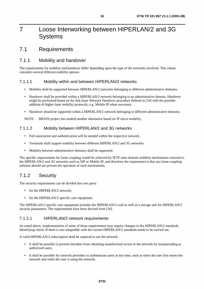
7.1.2.1 HIPERLAN/2 network requirements
As noted above, implementation of some of these requirements may require changes to the HIPERLAN/2 standards.Identifying which of them is not compatible with the current HIPERLAN/2 standards needs to be carried out.
A valid HIPERLAN/2 subscription shall be required to use the network.
• It shall be possible to prevent intruders from obtaining unauthorized access to the network by masquerading asauthorized users.
• It shall be possible for network providers to authenticate users at any time, such as when the user first enters thenetwork and while the user is using the network.

ETSI
ETSI TR 101 957 V1.1.1 (2001-08)17
• It shall be possible to detect and prevent the fraudulent use of the network. Audit logs of security related eventswill need to be produced.
• It shall be possible to blacklist users.
• It shall be possible for an AP to cause an immediate termination of the access provided to a user.
• It shall be possible for the network to authenticate the origin of user traffic, signalling data and control data.
• It shall be possible to prevent intruders from restricting the availability of services by logical means.
• It shall be possible to protect against unauthorized modification of user traffic.
• It shall be possible to protect against unauthorized modification of certain signalling data and control data.
• It shall be possible to protect against unauthorized modification of user-related data that is stored or processed bya provider.
• It shall be possible to ensure the origin, integrity and freshness of authentication data, particularly of the cipherkey.
• It shall be possible to protect the confidentiality of certain signalling data and control data.
• It shall be possible to protect the confidentiality of user traffic.
• It shall be possible to protect the confidentiality of user-related data that is stored or processed by a provider.
• It shall be possible to protect the confidentiality of user-related data stored by the user in the HIPERLAN/2specific user equipment.
7.1.2.2 HIPERLAN/2 specific user equipment requirements
• It shall be possible to control access to HIPERLAN/2 specific data (protocol intervention).
• It shall not be possible to access HIPERLAN/2 specific data that is only intended to be used for securitypurposes, e.g. authentication keys and algorithms.
• It shall be difficult to change the identifier.
7.1.2.3 Comparison with HIPERLAN/2 capabilities
After looking at the current HIPERLAN/2 specification some issues have been identified as needing further attention inorder to fulfil the requirements. These issues are:
1) There does not seem to be any replay protection. The challenge needs to be sequential to assure that the samechallenge is not sent several times.
2) After a user leaves a multicast group (implementation using multicast MAC ID) the key needs to be changed inorder to assure that the user, that is no longer part of the multicast group, can no longer gain access to multicastinformation.
3) Integrity protection is needed and a separate key should be used for this purpose.
4) The AP should be able to re-authenticate the user if desired.
5) The AP should be able to initiate a key refresh even if the lifetime of the session key has not yet expired.
6) Messages between an AP and the AAAL need to be well protected. This should be done with the standardfacilities provided by the AAA protocol or other IP security mechanisms (e.g. IPSec security associationsbetween the AP and AAAL).

ETSI
ETSI TR 101 957 V1.1.1 (2001-08)18
7.1.3 Quality of Service
Note that one of these requirements below, would also apply to a non-3G interworking HIPERLAN/2 networks. Latermore detailed system requirements on the provisioning of IP QoS in HIPERLAN/2 networks are provided. In the loosecoupling case it is not the intention to replicate/use the UMTS QoS mechanisms.
Overall Requirements
• QoS provisioning in HIPERLAN/2 networks should be subject to user's subscription.
• It should be possible for a HIPERLAN/2 network operator to monitor the QoS provided to the users.
• It should be possible to charge a user based on the level of QoS provided and on the QoS subscribed.
• The provisioning of QoS in HIPERLAN/2 networks should have a minimum impact on the provisioning of QoSin 3G networks.
• It should be possible for applications to request QoS treatment for their communications through one mechanismindependently of the access network used (i.e. UTRAN or HIPERLAN/2 network).
• It shall be possible to prevent unauthorized users to send (upstream) inadmissible data through the network.
• It should be possible to include HIPERLAN/2 related service/QoS subscription of a HIPERLAN/2-3G user inthe HLR/HSS or an authentication and authorization entity such as an AAAH. This possibility requires furtherstandardization.
• Within HIPERLAN/2 networks, QoS mechanisms towards external networks should be aligned with the IPmechanisms used on the 3G Gi interface [22] (in order to simplify interworking with the operator's ISPplatform). Additionally it should be possible to easily integrate, in the future, the IP Multimedia Subsystem QoSrequirements.
• QoS authorization should be performed locally. Once the service/QoS profile is downloaded to the local domain,the authorization is accomplished in the local domain to minimize signalling.
IP QoS requirements
By using existing or emerging IETF protocols (e.g. RSVP [16], COPS [17]), the HIPERLAN/2 and 3G domains caninterwork without extensive additional work. From the QoS perspective, the focus in this clause will be from the end-user part through the HIPERLAN/2 network connected to an IP network. The requirements to fulfil the end-to-endquality of service are outside the scope of the present document.
It is a requirement to be able to differentiate between MTs connected to one and different APs, to fulfil this requirement"policy-based" server scan be used. It is recommended that functionalities like user profile, IP policy handling andtraffic conditioning are also included in this node and could thereby act as a DiffServ boundary node. Thisdifferentiation is needed to ensure that resource (e.g. bandwidth) allocation and (re)-negotiation is properly performed.For example, when a user with higher priority entering the network using a real time application will not result in thatanother user with lower priority will be out of resources or logged out.
The provisioning of IP QoS should fulfil the following requirements partly taken from [1], [18] and [19]:
• The IETF's Differentiated Services should be supported via the priorities in Ethernet CL.
• The implementation of DiffServ classes EF (Expedited Forwarding) and AF (Assured Forwarding) shall complywith [18] and [19].
• The mapping between IEEE 802.1p priority levels (0-7 bits) and IP DiffServ (DSCP in the TOS byte should besupported.
• It should be possible for the operator to control/configure the mapping between IEEE 802.1p (priority bits) andDiffServ classes.
• QoS parameter mapping from the IP-application parameters to IEEE 802.1p priority levels (0-7 bits) in MT shallbe supported.

ETSI
ETSI TR 101 957 V1.1.1 (2001-08)19
• The policy-based server must be able to perform the traffic classification, shaping (re)-marking, QoSdifferentiation based on profile, SLA etc for both incoming and outgoing traffic.
• Support of IETF based protocol COPS (Common Open Policy Service) [17] intended for communication ofpolicy request, decisions and policy provisioning.
7.2 System architectureThis clause introduces the system architecture that is required to support loose coupling. In order to provideHIPERLAN/2 access for this scenario the HIPERLAN/2 network as described for corporate access can be used[H2GF SFA]. However, it is useful to split up authentication into a server and a client part where the client part residesat the premises of the HIPERLAN/2 network and the server part may reside in the public operator's cellular network.Refer to figure 2 for NAI centric architecture.
Figure 4: Void

ETSI
ETSI TR 101 957 V1.1.1 (2001-08)20
AP
AP
Layer2network
Routerwith
foreignagent
MTwith
(U)SIM
Gr
HLR
AAAL
GGSNwith
foreignagent
SGSNRNCNode B
AAAH
IP network
(U)SIM IWU
The line between (U)SIM IWU and theAAAH might instead go directly between
AAAL and AAAH
Figure 5: (U)SIM centric system architecture
Prerequisites and assumptions for figures 2 and 5:
1) The interworking between the HIPERLAN/2 access network and UMTS network uses (U)SIM centricauthentication and accounting towards the HLR.
2) Initially MIPv4 will be used.
3) The HIPERLAN/2 access network communicates with HLR via an interworking unit (IWU) that has an interfacewith the local AAA server.
ETSI
ETSI TR 101 957 V1.1.1 (2001-08)21
7.2.1 Protocol stacks
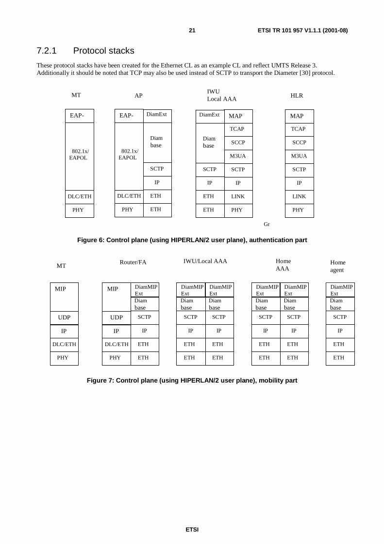
These protocol stacks have been created for the Ethernet CL as an example CL and reflect UMTS Release 3.Additionally it should be noted that TCP may also be used instead of SCTP to transport the Diameter [30] protocol.
MT APIWULocal AAA HLR
Gr
PHY
LINK
IP
SCTP
M3UA
SCCP
TCAP
MAP
PHY
LINK
IP
SCTP
M3UA
SCCP
TCAP
MAP
ETH
ETH
IP
SCTP
Diambase
DiamExt
ETH
ETH
IP
SCTP
Diambase
DiamExt
PHY
DLC/ETH
802.1x/EAPOL
EAP-
ETH
ETH
IP
SCTP
Diambase
DiamExt
ETH
ETH
IP
SCTP
Diambase
DiamExt
PHY
DLC/ETH
802.1x/EAPOL
EAP-
Figure 6: Control plane (using HIPERLAN/2 user plane), authentication part
MTRouter/FA IWU/Local AAA Home
AAA
PHY
DLC/ETH
MIP
IP
UDP
ETH
ETH
IP
SCTP
ETH
ETH
IP
SCTP
Diambase
DiamMIPExt
ETH
ETH
IP
SCTP
ETH
ETH
IP
SCTP
Diambase
DiamMIPExt
ETH
ETH
IP
SCTP
ETH
ETH
IP
SCTP
Diambase
DiamMIPExt
ETH
ETH
IP
SCTP
ETH
ETH
IP
SCTP
Diambase
DiamMIPExt
ETH
ETH
IP
SCTP
ETH
ETH
IP
SCTP
Diambase
DiamMIPExt
ETH
ETH
IP
SCTP
ETH
ETH
IP
SCTP
Diambase
DiamMIPExt
PHY
DLC/ETH
MIP
IP
UDP
Homeagent
Figure 7: Control plane (using HIPERLAN/2 user plane), mobility part

ETSI
ETSI TR 101 957 V1.1.1 (2001-08)22
MTRouter/FAEthernet
switch
PHY
DLC/ETH
ETH
ETH
IP
ETH
ETH
IP
CorrespondentNode
AP
PHY
DLC/ETH
Appl.
IP
TCP/UDP
PHY
LINK
Appl.
IP
TCP/UDP
ETH
ETH
IP
PHY
LINK
IP
ETH
ETH
ETH
ETH
ETH
ETH
ETH
ETH
ETH
ETH
ETH
ETH
Figure 8: User Plane
7.2.2 Interworking with UMTS Releases
The roaming, including charging and security issues, can be handled by the AAA (Authentication, Authorization andAccounting). For Release 4, the Home Subscriber Server (HSS) in the UMTS Core Network is the master databaseholding the subscriber data for e.g. charging and identity. In future Releases it may be possible to terminate AAAprotocols in the HSS.
Handover between the different networks can be provided through Mobile IP. The UMTS system (Release 3) optionallysupports Mobile IP for access independent roaming at IP level. Integration of MIP with UMTS has been describedin [20]. Mobile IP is further described in [2]. Generally speaking the direction of standardization within 3GPP is to havean AAA based HSS.
In UMTS it will be mandatory to support DiffServ at transport level and at user level in Release 4 there are several QoSmechanisms. For HIPERLAN/2 DiffServ can probably be supported via the priorities in Ethernet CL. QoS support is inRelease 4 divided on several functional entities, as described above in clause 7.1.3.
7.2.3 Interface definitions
Figure 9 presents the interfaces that are covered by the scope of the present document. Interfaces W.1 and W.2 wereintroduced in reference [15]. The present document defines the sub-parts of W.2.
A.2Diameter/RAD
HIPERLAN2 NAI
Diameter/RAD
(U)SIM Quintets
AP AAAL
MTNAI Centric-
IWU
W.2a
W.1
A.1
Figure 9: Loose Coupling Interface Definitions

ETSI
ETSI TR 101 957 V1.1.1 (2001-08)23
W.1
HIPERLAN/2 air interface standard as defined by reference [29].
W.2
The interface between the AP and the relevant core network. This is dependent upon the chosen convergence layer, sothat for example connection to a Corporate Intranet/Public Intranet would utilize the Ethernet CL.
W.2a
The name of this interface has already been defined by H2GF [24].
A.1
This interface is required for transmission of subscriber information from the (U)SIM card within the Mobile Terminal.It is transported using the IETF protocol Diameter or RADIUS.
A.2
This interface is required for transmission of user subscription data such as username and password and accountingdata. It is transported using the IETF protocol Diameter or RADIUS.
7.2.4 Subscriber data
There are three basic ways in which the subscriber management for HIPERLAN/2 and 3G users can be co-ordinated.
1) Have the interworking between the HIPERLAN/2 subscriber database and HLR/HSS. This is for the case wherethe interworking is managed through a partnership or roaming agreement. The administrative domains' AAAservers share security association or use an AAA broker.
2) The HIPERLAN/2 authentication could be done on the basis of a (U)SIM token.
3) The 3G authentication and accounting capabilities could be extended to support access authentication based onIETF protocols. This means either integrating HLR and AAA functions within one unit (e.g. a HSS unit), or bymerging native HLR functions of the 3G network with AAA functions required to support IP access.
Based on these different ways for subscriber management, the user authentication identifier can be on three differentformats:
1) NAI.
2) International Mobile Subscriber Identity (IMSI), requires a (U)SIM card.
3) IMSI in NAI, requires a (U)SIM card.
The user authentication identifier is pointed out to be something that could affect the HIPERLAN/2 standardizationwork and is therefore further discussed in clauses 7.2.4.1, 7.2.4.2, 7.2.4.3.
7.2.4.1 NAI as the user authentication identifier
Internet AAA protocols identify users with the Network Access Identifier (NAI). The NAI that is the userID submittedby the client during authentication (PPP or AAA). The NAI format is: user@realm. In mobility between differentadministrative domains, the purpose of the NAI is to identify the user as well as to assist in the routing of theauthentication request. Visited network can route an authentication request to the home domain (or forward it to aroaming broker) based on the realm.
A proposed possibility is to use NAI as the identification of a user in a HIPERLAN/2 IP network. This allows the usernot to have an existing be GSM/GPRS/UMTS subscription (i.e. a user can then decide only to subscribe toHIPERLAN/2). The HIPERLAN/2 standard is already prepared for the NAI as an authentication identifier. Accordingto existing standards [29], the NAI is mandatory in the BRAN Business Profile (i.e. corporate environment), thisfacilitate a future interworking between the corporate and public scenarios.
A consequence of using NAI is that for users with subscriptions to both GSM/GPRS/UMTS and HIPERLAN/2, thereneed to be a way to map the two.

ETSI
ETSI TR 101 957 V1.1.1 (2001-08)24
7.2.4.2 IMSI as the user authentication identifier
The subscribers of the cellular systems GSM/GPRS and UMTS are identified by the International Mobile SubscriberIdentity (IMSI), which is stored on a Subscriber Identity Module (U)SIM card, which is a smart card. The IMSI consistsof three parts; the Mobile Country Code (3 digits), the Mobile Network Code (2 digits) and the Mobile SubscriberIdentity Number (up to 10 digits). These digits together form a globally unique number. To be able to use the cellularsystem and its services the user need to be a native cellular subscriber. In order to establish an interworking betweenHIPERLAN/2 the user has to be authenticated in the HIPERLAN/2 network. The advantage of using the IMSI is that itis an international identifier that has been in use for some time. Another advantage of using IMSI would be that sinceIMSI is used for administrative purposes in mobile networks today, no mapping would be needed if it were used forHIPERLAN/2 as well. The drawbacks for using the IMSI as it is, as an authentication identifier for the HIPERLAN/2network are:
• IMSI is strongly related to GSM/GPRS/UMTS subscribers. For users that only subscribe to a HIPERLAN/2service no IMSI is available. It is foreseen that only some HIPERLAN/2 operators will offer an interworkingwith the cellular systems.
• It is also foreseen that the public HIPERLAN/2 network will be widely spread through partnership and roamingagreements. It is therefore important that the authentication identifier is consistent between differentHIPERLAN/2 operators. Furthermore the IMSI as an authentication identifier requires standardization work forBRAN (because IMSI is not currently among the 6 identifiers within the BRAN standard).
7.2.4.3 IMSI in NAI as the user authentication identifier
The next feasible possibility is to use the IMSI in NAI [ref: MobileIP I-D]. This means that the IMSI is encoded as aNAI, where the username portion of the NAI contains the IMSI as a string of digits, and the realm portion identifies theAAA server. The IMSI itself contains enough information to identify the GSM operator and to route the authorizationrequests to the subscriber's home GSM operator. How this shall be solved requires further investigation and possiblystandardization in 3GPP and IETF.
7.2.4.4 Pre paid SIM
As far as the HLR within the core network is concerned, it cannot distinguish the difference between a customer who ispre-paid or not. Hence, this prevents a non-subscriber to this specific 3G network from using the system, if the operatorwishes to impose this restriction.
As an example, pre-paid calls within a 2G network are handled via an Intelligent Network (IN) probably co-locatedwith the HLR. When a call is initiated, the switch can be programmed with a time limit, or if credit runs out the IN cansignal termination of the call. This then requires that the core network knows the remaining time available for any givencustomer. Currently the only signals that originate from the IN are to terminate the call from the network side.
This may be undesirable in a HIPERLAN/2 - 3G network, so that a more graceful solution is required. A suitablesolution is to add pre-paid SIM operation to the system together with hot billing (i.e. bill upon demand) or triggeredsession termination. This could be achieved either by the AAAL polling the core network utilizing RADIUS todetermine whether the customer is still in credit, or by using a more complicated protocol such as Diameter whichallows network signalling directly to the mobile terminal.
The benefit of this approach is to allow the operator to present the mobile user with a web page (for example), as thepre-paid time period is about to expire, allowing them to purchase more airtime.
All these solutions would require an increased integration effort with the core network subscriber managementsystem (ABC). Further additional services such as CAMEL may also allow roaming with pre-paid SIM cards.
7.2.5 Mobility and handover
In line with the requirements as stated for mobility and handover (see clause 7.1.1), the system architecture supportingthis is divided up into two parts: mobility within and between HIPERLAN/2 networks, and mobility betweenHIPERLAN/2 networks and any other network. (The 'other' network could be a different HIPERLAN/2 network or a3G network).

ETSI
ETSI TR 101 957 V1.1.1 (2001-08)25
7.2.5.1 Mobility within and between HIPERLAN/2 Islands
In the loose coupling approach, the mobility within the HIPERLAN/2 network is provided by native HIPERLAN/2(i.e. RLC layer) facilities, possibly extended by the convergence layer in use (e.g. the current Ethernet CL, or a futureIP CL). This functionality should be taken unchanged in the loose coupling approach, i.e. handover between accesspoints of the same HIPERLAN/2 network does not need to be considered especially here. This is justified by thefollowing:
- the network handover capabilities of HIPERLAN/2 RLC are supported by both terminals and APs;
- given that HIPERLAN/2 network handover is supported, further details for completing the mobility betweenaccess points are provided by convergence layer dependent functionality;
- completion of this functionality to cover interactions between the APs and other parts of the network (excludingthe terminal and therefore independent of the air interface) are currently under development outside BRAN. Inthe special case where the infrastructure of a single HIPERLAN/2 network spans more than one IP subnetwork,some of the above approaches assume an additional level of mobility support that may involve the terminal.
NOTE: The following message sequence diagrams utilize the HLR as an example of a subscriber database and donot imply a suggested architecture for loose interworking.

ETSI
ETSI TR 101 957 V1.1.1 (2001-08)26
7.2.5.1.1 The MT registers to a foreign network
MT AP FA HAIWU/AAAL HLR AAAH
Basic HL2associationsignalling
Encryptionstartup
eapol-start
eapol-request-identity
eap-response-identity authentication-data request
authentication-response (rand, autn,...)
authentication-data request
authentication-data-response (rand, autn, xres,Ik, Ck)
eap-request-???
eap-response-??? (res,...) eap-response (res, ...)
check res=xres
successsuccess
continued
<ethernet up>
< E t h e r n e t o n L A N a v a i l a b l e >

ETSI
ETSI TR 101 957 V1.1.1 (2001-08)27
MT AP FA HAIWU/AAAL HLR AAAH
home-agent-answer
mip-agent-solicitation
mip-agent-advertisement
mip-registration -request
aaa-mobile-node-requestaaa-mobile-node-request
home-agent-request
aaa-mobile-node-answer
aaa-mobile-node-answermip-registration-reply
Figure 10: The MT registers at a foreign network
7.2.5.2 The MT moves to a new AP connected to a new foreign agent
MT APnew FAnew APold FAold HA HLR
mip-agent-solicitation
mip-agent-advertisement
IWU/AAAL
Basic hl2associationsignalling
See the message sequence chart "The MT registers at a foreign network"
Old registration time expires
NOTE: The black circles designate the nodes that are affected by the expiration.
Figure 11: Sequence diagram. The MT moves to a new AP connected to a new foreign agent

ETSI
ETSI TR 101 957 V1.1.1 (2001-08)28
7.2.5.3 Mobility Between HIPERLAN/2 access networks and 3G access networks
For the case of mobility between HIPERLAN/2 and 3G access networks, recall that we have the following basicarchitecture:
- An MT attaches to a HIPERLAN/2 network, authenticates and acquires an IP address. At that stage, it can accessIP services using that address while it remains within that HIPERLAN/2 network. If the MT moves to a networkof a different technology (i.e. UMTS), it can re-authenticate and acquire an IP address in the packet domain ofthat network, and continue to use IP services there.
- This basic case has been referred to as AAA roaming. Note that while it provides mobility for the user betweennetworks, any active sessions (e.g. multimedia calls or TCP connections) will be dropped on the handoverbetween the networks because of the IP address change (e.g. use DHCP). However, this provides mobility inaccordance with the requirements of clause 7.1.1.
It is possible to provide enhanced mobility support, including handover between HIPERLAN/2 access networks and 3Gaccess networks in this scenario by using servers located outside the access network. Two such examples are:
• The MT can register the locally acquired IP address with a Mobile IP home agent (HA) as a co-located care-ofaddress, in which case handover between networks is handled by Mobile IP. This applies to MIPv4 and MIPv6(and is the only mode of operation allowed for MIPv6).
• The MT can register the locally acquired IP address with an application layer server such as a SIP proxy.Handover between two networks can then be handled using SIP (re-invite message).
Note that in both these cases, the fact that upper layer mobility is in use is visible only to the terminal and core networkserver, and in particular is invisible to the access network. Therefore, it is automatically possible, and can beimplemented according to existing standards, without impact on the HIPERLAN/2 network itself. We thereforeconsider this as the basic case for the loose coupling approach.
Three options for further study are:
• The use of a Foreign Agent care-of address (MIPv4 only). This requires the integration of Foreign Agentfunctionality with the HIPERLAN/2 network, but has the advantage of decreasing the number of IPv4 addressesthat have to be allocated. On the other hand, for MTs that do not wish to invoke global mobility support in thiscase, a locally assigned IP address is still required, and the access network therefore has to be able to operate intwo modes.
• The option to integrate access authentication (the purpose of this loose coupling standard) with Mobile IP HomeAgent registration (If Diameter is used, it is already present). This would allow faster attach to the network in thecase of a MT using MIP, since it only requires one set of authentication exchanges; however, it also requiresintegration on the control plane between the home AAA server and the Mobile IP Home Agent itself. Thecurrent assumption that this integration should be carried out in a way that is independent of the particular accessnetwork being used, and is therefore out of scope of this activity.
• The implications of using services (e.g. SIP call control) from the UMTS IMS (Internet Multimedia Subsystem),which would provide some global mobility capability. This requires analysis of how the IMS would interface tothe HIPERLAN/2 access network (if at all).
7.2.5.3.1 The MT moves from UMTS/UTRAN to HIPERLAN/2
It is assumed that the MT has both HIPERLAN/2 and UMTS/UTRAN coverage. It also assumed that the MT remainsattached to the UMTS core network by sending routing area updates with a periodicity shorter than the mobilereachable timer in SGSN. The MT will then be in PMM-IDLE mode towards the core network. It also assumes that theHA can keep the registration without sending duplicate packets to both FAs. This is not possible in MIPv4 today.

ETSI
ETSI TR 101 957 V1.1.1 (2001-08)29
UTRAN
HL2
Figure 12: Logical encapsulation of HIPERLAN/2 within UTRAN
MT COREIETF/HLR
See MSC "The MTregisters at a
foreign network"
Routing area update
Routing area update accept
Routing area update complete
Repeated as long asneeded
NOTE: "IETF/HLR" above designates all the IETF nodes and severs + the HLR.
Figure 13: Sequence diagram. The MT moves from UTRAN to HIPERLAN/2 while at the same timekeeping the core network attachment and the MIP registration

ETSI
ETSI TR 101 957 V1.1.1 (2001-08)30
7.2.5.3.2 The MT moves from HIPERLAN/2 to UMTS/UTRAN. MIP registration in UMTSstill valid
It is assumed that the MT has both HIPERLAN/2 and UTRAN coverage. It also assumed that the MT is alreadyattached to the core network and is in PMM-IDLE mode and that the MIP registration is still available.
MT COREIETF/HLR
Service request
Radio access bearer assignment request
UTRAN
Security functions
Radio access bearer assignment response
SGSN initiated PDP context modification
Old registration expires
Figure 14: Sequence diagram. The MT moves from HIPERLAN/2 to UTRAN. It is still attached toUTRAN and the MIP registration is still there

ETSI
ETSI TR 101 957 V1.1.1 (2001-08)31
7.2.5.3.3 MT moves from HIPERLAN/2 to UMTS/UTRAN. MIP registration in UTRAN notvalid
MT COREIETF/HLR
Service request
Radio access bearer assignment request
UTRAN
Security functions
Radio access bearer assignment response
SGSN initiated PDP context modification
Old registration expires
See sequence diagram "MT attaches to a foreign access network"
Figure 15: Sequence diagram. The MT moves from HIPERLAN/2 to UTRAN. The UMTS MIPregistration is not valid
7.2.5.4 Handover Triggers
For handover, the terminal must have enough information to be able to make a handover decision for itself, or be able toreact to a network decision to handover. Indeed these decision driven events are referred to as triggers, resulting inNetwork centric triggers or Terminal centric triggers.
Simple triggers include the following:
• Network Centric: Poor network resources or low bandwidth. Poor or changing QoS provided by the 3G network.
• Terminal Centric: Poor signal strength. Change of QoS.
The BRAIN project documentation addresses the different trigger mechanisms in further detail.
7.2.6 Security
For Loose Coupling it is possible to use the security features described in the current HIPERLAN/2 standard, with someadditions. As mentioned in the introduction there are two variants of security that can be considered.

ETSI
ETSI TR 101 957 V1.1.1 (2001-08)32
7.2.6.1 NAI centric
Within this approach HIPERLAN/2 users may be either existing 3G subscribers or just HIPERLAN/2 networksubscribers.
These users want to make use of their existing data devices (e.g. Laptop, Palmtop) without additional hardware/softwarerequirements. For both users and mobile operators it is beneficial to be able to base the user authentication andaccounting on existing cellular accounts, as well as to be able to have HIPERLAN/2-only operators and users; in anycase, for reasons of commonality in MT and AP development it is important to be able to have a single set of AAAprotocols which supports all the cases.
This scenario is driven by the requirement to add only minimal software functionality to the terminals (e.g. bydownloading java applets), so that the use of a HIPERLAN/2 mobile access network does not require other changes inthe functionality (hardware or software) than those required by broadband wireless data access in the corporate, orhome scenarios.
7.2.6.2 (U)SIM centric
The (U)SIM centric definitely requires that a user is a native cellular subscriber while - in addition and distinctly fromthe NAI centric approach - standard cellular procedures and parameters for authentication are used (e.g. (U)SIMquintets). In this way a mobile subscriber using a HIPERLAN/2 mobile access network for broadband wireless dataaccess will appear as a normal cellular user employing standard procedures and interfaces for authentication purposes. Itis important to notice that for this scenario (U)SIM card functionality is required in the user equipment. (U)SIMprovides new and enhanced security features in addition to those provided by 2G SIM (e.g. mutual authentication) asdefined by 3GPP. Note that to provide equivalent security functionality within HIPERLAN/2 as is required for 3Gpublic operations (e.g. periodic re-authentication) it will be necessary to enhance the base HIPERLAN/2 standardsspecifically the authentication requirements of the RLC [29].
For the NAI centric approach there is no need to integrate the HIPERLAN/2 security architecture with the UMTSsecurity architecture [23]. It might not even be necessary to implement all of the HIPERLAN/2 security features ifsecurity is applied at a higher level, such as using IPSec at the IP level. An additional situation that has to be consideredis the use of pre-paid SIM cards. This scenario will introduce additional requirements for hot billing and associatedfunctions.
7.2.6.3 Key exchange
Key agreement for confidentiality and integrity protection is an integral part of the UMTS authentication procedure, andhence the UTRAN confidentiality and integrity mechanisms should be reused within the HIPERLAN/2 wheninterworking with a 3G core network. This will also increase the applied level of security.
The Diffie-Hellman encryption key agreement procedure could be used to improve user identity confidentiality. Byinitiating encryption before UMTS AKA is performed, the user identity will not have to be transmitted in clear over theradio interface, as is the case in UMTS when the user enters a network for the first time. Thus, this constitutes animprovement compared to UMTS security.
It is also important to have a secure connection between APs within the same network if session keys or other sensitiveinformation are to be transferred between them. A secure connection can either be that for some reason they trust eachother and no one else can intercept the communication between them or that authentication is performed and integrityand confidentiality protection are present.

ETSI
ETSI TR 101 957 V1.1.1 (2001-08)33
7.2.6.4 (U)SIM vs no (U)SIM
Another issue under discussion is whether a (U)SIM shall be used or not. Given the assumption that a (U)SIM is a smartcard that needs to be inserted into the terminal the following two paragraphs can be used as input to the discussion. Itshould be noted that the way (U)SIM is discussed here is independent of authentication identifier and it is not necessaryto use 3G procedures, it is simply a storage place as discussed below.
From a security perspective there are several advantages with using a (U)SIM, the main one being that certain securityparameters, such as the authentication key, never leaves the (U)SIM. Another, not security related, advantage is that thecalculations required for authentication are performed on the (U)SIM and no extra software is needed for this purpose.The user simply has to plug in the card to get it working. One downside is that there is a need for a card reader. If the(U)SIM card reader is not integrated with the HIPERLAN/2 network card, the terminal will need an extra device/slotfor the (U)SIM.
If a (U)SIM is not used, the same information needs to be stored in some other way, such as in software on the terminalor on a disc. This solution does not require an extra device, but on the other hand, the security parameters can beaccessed and copied quite easily.
7.2.6.5 Authentication, Authorization and Accounting architecture
Authentication, Authorization and Accounting functionality needs to be handled by the HIPERLAN/2 network. Tosupport both scenarios outlined above; the AAA server is split into a client (AAAL) and a server (AAAH) part. TheAAAH is likely to, but does not have to, be part of a mobile network (e.g. UMTS) or interwork with equivalent mobilenetwork entities (e.g. 2G, 2.5G mobile networks).
The AAAL supports APs within the HIPERLAN/2 access network with AAA functionality. This device supports boththe NAI and (U)SIM centric scenario, resulting in a single access network that can support both forms of terminals.(U)SIM quintets are directed over the A.1 interface, whilst AAA messages are routed to the AAAH via the A.2interface as shown in figure 9.
The present document only considers the interaction between the AP and AAAL and the network architecture furthertowards the core is included for informative purposes. However, note also that the AAAL may simply be an AAA proxyserver, in which case the W.2a protocol is most easily described as a combination of the A.1 and A.2 protocols.
There are two methods of achieving the link between the AAAH and the HLR, which interfaces the AAA messagesreceived by the AAAH to the core network databases, as shown in figure 2:
- linking to the subscriber database using a proprietary protocol;
- linking to the 3G AuC (Authentication Centre) (MAP/SS7) using a standardized interface such as ZB as definedby reference [12].
7.2.7 Quality of Service
This clause discusses the mechanisims that could be used to meet the requirements isted in clause 7.1.3. In UMTS itwill be mandatory to support DiffServ at transport level and at user level in Release 4. For HIPERLAN/2 DiffServ canprobably be supported via the priorities in the Ethernet CL (TS 101 493-2 [28]). Interoperability between HIPERLAN/2and UMTS may therefore be implemented in two phases, first a best effort in Release 3 and then with QoS support forRelease 4.
The Differentiated Services architecture is based on a simple model where traffic entering a network is classified andpossibly conditioned at the boundaries of the network, and assigned to different behaviour aggregates. Each behaviouraggregate is identified by a single Differentiated Services codepoint (DSCP, the value of the TOS byte). Within the coreof the network, packets are forwarded according to the per-hop behaviour or PHBs associated with the DifferentiatedServices codepoint. A PHB can result in different classes of traffic receiving different performance. There are twostandardized PHB groups in IETF:
- expedited Forwarding (EF) PHB: The EF PHB can be used to build a low loss, low latency, low jitter andassured bandwidth;
- assured Forwarding (AF) PHB: AF PHB group provides delivery of IP packets in four independently forwardedAF classes. Within each AF class, an IP packet can be assigned one of three different levels of drop precedence.

ETSI
ETSI TR 101 957 V1.1.1 (2001-08)34
In HIPERLAN/2 a CL has two main functions: adapting service request from higher layers to the service offered by theDLC and to convert the higher layer packets (SDUs) with variable or possibly fixed size into a fixed sized that is usedwithin the DLC. The generic architecture of the CL makes HIPERLAN/2 suitable as a radio access network fordiversity of networks, e.g. Ethernet, IP, UMTS, etc. There are currently two different types of common convergencesublayers defined: cell-based and packet-based. The structure of the packet-based CL (TS 101 493 [28]) with a commonand several service-specific parts allows for easy adaptation to different configurations and fixed networks.
The Ethernet SSCS (Service Specific Convergence Sublayer) offers two QoS schemes:
- best effort: mandatory to support and treats all traffic equally, so that guarantees can be provided.
- IEEE 802.1p: priority schemes, optional and separates traffic in different priority queues as described inIEEE 802.1p (see below).
IEEE 802.1p [26] provides priority mechanism to enable QoS in LANs. These mechanisms have been incorporated intoIEEE 802.1d (see [26]). Eight (numbered 0-7) different priority levels are defined. The user priorities are mapped one-to-one or many-to-one to queues, depending on the number of queues supported. In HIPERLAN/2 each queuecorresponds to one DLC user connection.
Hence, the QoS mapping between the IP QoS (DiffServ) and IEEE 802.1p priority schemes should be supported andconfigurable by the operator.
In summary, there are several issues to consider here:
What type of QoS is required?
This is dependent upon the layers concerned:
• DLC User Control as defined by the HIPERLAN/2 standards (TS 101 761 [29]);
• convergence Layer QoS;
• Upper Layer signalling (e.g. IEEE 802.1p, RSVP).
For each network element, the AP will have knowledge of the CL used.
How is it engineered?
This is implementation dependent and should not be standardized.
How is it controlled?
It will be controlled by algorithms such as fair sharing and again these are implementation dependent.
7.2.8 User Traffic Management
User traffic will be carried by the CL as defined within the stack as shown in figure 1. Hence the management of thistraffic is beyond the scope of the present document.
7.2.9 End user device (terminal)
For interworking with 3G, the terminal can be of different kinds, like:
• a multimode terminal, i.e. one terminal or one module such as a PC card with many different radio interfaces;
• separated modules with different radio interfaces. The modules are used in a single terminal. A driver selectionfunction between active modes in a terminal can be used to handle modules with different radio interfaces. (Howdo then split the (U)SIM card).
• Separated modules with different radio interfaces. The modules can be used in separated terminals. These twoterminals can communicate over a third interface, e.g. Bluetooth, which can enable the interworking betweenHIPERLAN/2 and 3G networks.

ETSI
ETSI TR 101 957 V1.1.1 (2001-08)35
If the case is that the IMSI shall be used for subscriber identification in the HIPERLAN/2 environment, it requires thatthe terminal have a smart card reader. However, as more and more manufacturers (e.g. Laptops) are building in theWLAN module it can limit the users' choice of HIPERLAN/2 operator if the terminal has not got a smart card reader.(Hence can still use NAI approach or external SIM card reader).
8 Tight interworking HIPERLAN/2 and 3G
8.0 GeneralThis clause only considers UMTS as a specific example of 3G technology. Its scope is to investigate some of theControl Plane issues. User plane issues are not considered.
8.1 Requirements
8.1.1 Mobility and handover
Two main types of mobility and handover should be handled: between HIPERLAN/2 cells and between HIPERLAN/2and UTRAN.
The radio controller in UTRAN is called RNC and for HIRAN IWU, since the main function for HIRAN isinterworking rather than controlling the radio network. Thus, an AP may be connected to an IWU while a "node B" isconnected to an RNC.
The mobility and handover are "layered": change of APs/node Bs connected to the same IWU/RNC; change ofAPs/node Bs connected to different IWU/RNCs, thus change of IWU/RNC and change of APs/node Bs connected todifferent IWUs/RNCs and different SGSNs, thus change of IWU/RNC and SGSN.
For both of the main types, mobility and handover should be handled.
Seamless handover at the link layer should not be required. It means that higher layers looses packets or useretransmission mechanisms.
It is an important requirement at handover to keep the radio access bearers and the sessions. It is also an importantrequirement that the user of an end user service experiences the interruption as short, especially for the conversationaland streaming service classes. It is mainly a matter of handover time. The maximum time for handover should be thefollowing:
1) Low 100 ms for intra-IWU handover between HIPERLAN/2 IWUs.
2) Below 300 ms for inter-IWU handover between HIPERLAN/2 IWUs.
3) Below 5 s for inter-IWU/RNC handover between a HIPERLAN/2 IWU and a UTRAN RNC.
8.1.2 Security
The same security level as for other UMTS access network technologies should be required.
The requirements on security of 3GPP services described in [10] are used as a basis for the security requirements in thiscase. The important access network related functions that should be supported are:
1) A valid (U)SIM shall be used to access any 3G service;
2) Authentication of users and serving network;
3) Authentication of data origin;
4) Access control to limited access to intended users;
5) Protection against modification of signalling;

ETSI
ETSI TR 101 957 V1.1.1 (2001-08)36
6) Confidentiality protection of user traffic, user related identities and signalling data;
7) Terminal barring;
8) Terminal related security requirements like protection against of user data stored in the (U)SIM should also beconsidered.
8.1.3 Quality of Service
Reference [1] lists a number of high level requirements for the QoS; end user, general and technical. All of these highlevel requirements are applicable to HIPERLAN/2 as well.
The UMTS bearer service is a part of the end-to-end service. The external bearer service cannot be controlled byUMTS, nor can the bearer service internal to the end user device be. Therefore, the present document treats only theUMTS part. The UMTS bearer service is further subdivided into Radio access bearer service and Core network bearerservice. The radio access bearer part is subdivided into the Radio bearer and the Iu bearer. The QoS discussion in thepresent document concentrates on the Radio access bearer part since it is this one that affects HIPERLAN/2.
Reference [1] identifies four QoS classes:
1) Conversational;
2) Streaming;
3) Interactive;
4) Background.
A HIPERLAN/2 standard should support all of them. It should be optional to support them in a product implementation.It would probably be advantageous to start a standardization with the two lowest QoS classes; interactive andbackground. The main distinguishing factor between the traffic classes is how delay sensitive the traffic is, both delayand delay variation, but also the acceptable SDU error ratio.
Mapping the QoS between HIRAN and, for example UTRAN, needs further studies.
A full HIPERLAN/2 standard should support the QoS attributes listed below.
The following UMTS bearer service attributes are described in [1]:
• Traffic class.
• Maximum bit rate. Maximum number of bits delivered by UMTS and to UMTS at a SAP within a period oftime, divided by the duration of the period.
• Guaranteed bit rate. Guaranteed number of bits delivered by UMTS at a SAP within a period of time, divided bythe duration of the time.
• Delivery order. Whether the UMTS bearer shall provide in-sequence SDU delivery or not.
• Maximum SDU size. The size may vary. Only applicable if SDU format information is not specified.
• SDU format information. List of possible exact sizes of SDUs.
• SDU error ratio. The fraction of SDUs lost or detected as erroneous.
• Residual bit error ratio. The undetected bit error ratio in the delivered SDUs.
• Delivery of erroneous SDUs, yes or no.
• Transfer delay. Maximum delay for 95th percentile of the distribution of delay for all delivered SDUs during thelifetime for a bearer service.
• Traffic handling priority. The relative importance for handling of all SDUs belonging to the UMTS bearercompared to the SDUs of other bearers.

ETSI
ETSI TR 101 957 V1.1.1 (2001-08)37
• Allocation/retention priority. Relative importance compared to other UMTS bearers for allocation and retentionof the UMTS bearer. Subscription parameter.
The HIPERLAN/2 standard does not support the QoS attributes at present It would be advisable though, to develop thestandard in two steps, where step one covers the lowest traffic class where HIPERLAN/2 probably can keep the ethernetmechanisms available now. Step 2 could then add at least the interactive and the streaming classes and perhaps also theconversational class.
8.2 System architecture
8.2.1 General
The discussions below have the following prerequisites:
1) Generally, the standard and design of a HIRAN should be independent of the standard and design of otherUMTS access technologies like UTRAN.
2) The Iuhl2 interface (SGSN - IWU) should be used as it is specified by 3GPP, that is, Iu. Some small changesmay be necessary.
3) The Iurhl2 and Iurhl2/utr interfaces (IWU - IWU and IWU - RNC) will be discussed later in the presentdocument.
4) The Uuhl2 interface (AP - MT) should be modified in a way that reflects the signalling over the Iuhl2interface.
A number of UMTS/UTRAN terms are used in clause 8.2. This does not mean that HIRAN should use the samesolutions but rather serve as a guide to similarities and differences between the two access technologies.
8.2.2 Iu/Iuhl2
See reference [5].
It is assumed that the Iuhl2 interface, RANAP included, will be used as it is specified by 3GPP, with a minimumamount of changes.
SCCP
M3UA
SCTP
RANAP
IP
AAL5
SDHETSI/
SONET
ATM
NOTE: RANAP is placed in the radio network layer control plane.
Figure 16: The control plane of Iu and Iuhl2

ETSI
ETSI TR 101 957 V1.1.1 (2001-08)38
GTP-U
UDP
IP
Iu radio networklayer user plane.Transparent mode
AAL5
ATM
ETSI/SONET
SDH
NOTE: Iu and Iuhl2 user planes are placed in the radio network layer user plane. GTP-U is the user plane of theGPRS Tunnelling Protocol.
Figure 17: The user plane of Iu and Iuhl2
There is no general support of broadcast and multicast at present in UMTS.
It is assumed that the transparent mode of the user plane of Iu will be used for HIPERLAN/2. Discussions within 3GPPare on going to standardize a special support mode for IP telephony, and in that case it should be adopted forHIPERLAN/2 as well. At present, the support mode is used only for AMR coded speech in the circuit switchednetwork.
The RANAP signalling belongs to the radio network layer control plane and is placed on top of the transport networklayer user plane. There are two main ways of using RANAP: one is mapped to the IWU signalling and the second one isto carry data between the core network and the UE transparently and there is no mapping to IWU signalling. In thelatter case, signalling is carried by the RANAP signal DIRECT TRANSFER.
An important division is also whether relocation is used or not. Relocation is a substantial part of the RANAPsignalling. Relocation means that the tunnel between SSGN and IWU/RNC is moved from one IWU/RNC to anotherone.
If relocation is used, most RANAP messages will also be used for HIPERLAN/2. The following signals are used forrelocation:
• RELOCATION REQUIRED
• RELOCATION COMMAND
• RELOCATION PREPARATION FAILURE
• RELOCATION REQUEST
• RELOCATION REQUEST ACKNOWLEDGE
• RELOCATION FAILURE
• RELOCATION DETECT
• RELOCATION COMPLETE
• RELOCATION CANCEL
• RELOCATION CANCEL ACKNOWLEDGE

ETSI
ETSI TR 101 957 V1.1.1 (2001-08)39
8.2.3 Iur, Iurhl2, Iurhl2/utr. The use of RNSAP signalling for HIPERLAN/2
See references [6] and [7].
ATM
AAL5
IP
SCTP
M3UA
SCCP
RNSAP
NOTE: This is not to imply that the solution should be used for HIRAN.
Figure 18: The protocol stack of the control plane of Iur for UTRAN
In order to offload the core network at handover between two IWU/RNCs, the Iur, Iurhl2, Iurhl2/utr interface can beused for signalling and user data. It could also be used for signalling only. The IWU/RNCs may be from differentmanufacturers and they may belong to different radio technologies, for example HIPERLAN/2 and UTRAN.
The radio network control plane for UTRAN is realized with RNSAP that is placed on top of the transport networklayer. The radio network user plane is also placed on top of the transport network user plane, but with a much simplerprotocol stack below it. RNSAP procedures are divided into four parts: Basic mobility, Dedicated Channel, Commontransport channel, Global.
The main reason for using Iur is that it speeds up handover. The main reason for using a standardized interface is that itshall be possible to communicate between RNCs controlling different types of access networks. It is the signallingprotocol, e.g. RNSAP for UTRAN, that will control what happens over the Iub and Uu interfaces.
The Iur interface as it is standardized at present is very UTRAN oriented and cannot be used as it is by HIPERLAN/2.There are three ways to proceed here:
1) Do not use Iur, Iurhl2, Iurhl2/utr at all.
2) Standardize an Iurhl2 that is defined for communication between HIPERLAN/2 IWUs only. Handover to andfrom UTRAN does not use Iurhl2. A HIPERLAN/2 only Iurhl2 could be relatively simple.
3) Use a subset of the Iur and make changes to that subset. This would allow some basic functionality betweenIWU/RNC of different types. The small subset would probably be basic mobility. The basic mobility consists ofthe messages uplink signalling transfer, downlink signalling transfer, paging and relocation commit.
4) Use a full Iurhl2/utr. Very complex as this requires the mixing of two radio interfaces within one protocol.
In order to simplify the standardization, at least for an initial phase, points 1 or 2 above could be a good way to start.
8.2.4 Iub/Iubhl2
Some reasoning about the functional distribution between the AP and an IWU can be made here.
It could be assumed that the AP handles all functions that can be isolated to its own cell. The IWU handles functions forinterworking with the UMTS core network and with other IWUs. The IWU consists of a control plane unit and a userplane unit. The AP to AP communication does not require any repacketization, so this is a switch. TheHIPERLAN/2/SGSN communication needs repacketization, so this is a user plane gateway.

ETSI
ETSI TR 101 957 V1.1.1 (2001-08)40
8.2.5 Uu/Uuhl2
See references [8] and [9].
8.2.5.1 General
It is assumed that the PHY (TS 101 475 [32]), DLC (TS 101 761-1 [29]) and RLC (TS 101 761-2 [29]) layers ofHIPERLAN/2 make up the basis for an UMTS interworking. It is assumed that PHY will not be affected, DLC to arelatively low extent (if any) and RLC to a relatively large extent for a full standard. The RLC part could bestandardized in steps though.
The discussion below treats a Uuhl2 and is based on an effort to compare the signals used for Iu, Uu and HIPERLAN/2RLC to see how the Uuhl2 could look like. There is no intention to use UTRAN signals in HIRAN just to keep thesignals alike. The UTRAN signals are used for guidance here.
8.2.5.2 Uu/Uuhl2 signalling
8.2.5.2.1 General
Below, HIPERLAN/2 RLC is the same thing as Uuhl2 control plane.
The important property is what information needs HIPERLAN/2 RLC signalling and what information can be carriedtransparently over the air. Transparent here means information that goes directly between the MT and the core network(SGSN) and is not processed by the HIPERLAN/2 controlling function, whether this function is placed in the AP or in aRadio Network Controller. It is only processed in the sense that there is a low level protocol conversion,repacketization.
HIPERLAN/2 RLC signalling is used when the controlling function of HIPERLAN/2 is involved at all control planelayers.
In the next parts of this clause, signalling will be classified in the following way:
1) existing HIPERLAN/2 RLC signals that can be used as they are;
2) existing HIPERLAN/2 signals that can be used after changes of the contents;
3) possible new HIPERLAN/2 RLC signals.
The following classifications can also be made at a future point:
1) transparent signals, going between MT and core network (NAS, Non Access Stratum);
2) HIPERLAN/2 RLC signals, being processed by HL IWU. All of the signals in the classification list abovebelong to this category.
And then also:
1) Signals that are caused by Iu/Iuhl2 signals;
2) Signals that are used by the HIPERLAN/2 radio network only.
Several bearers for signalling may be set up, depending on acknowledged or non-acknowledged, on transparent or non-transparent and on using a dedicated channel or a common channel.
8.2.5.2.2 Existing HIPERLAN/2 RLC signals that can be used as they are
1) RELEASE. RELEASE-ACK (RADIO BEARER handling). Iuhl2 related.
2) MAC-ID-ASSIGN. MAC-ID-ASSIGN-ACK. U-RNTI Iuhl2 related.
3) HANDOVER-REQUEST, HANDOVER-ASSOCIATION. See clause 8.2.5.2.4[], 3).
4) KEY-EXCHANGE-AP, KEY-EXCHANGE-MT. Probably not. If encryption and authentication are separated,there is a risk for a man-in-the-middle-attack.

ETSI
ETSI TR 101 957 V1.1.1 (2001-08)41
5) UNICAST-KEY-REFRESH, UNICAST-KEY-REFRESH-ACK. Probably not. If encryption and authenticationare separated, there is a risk for a man-in-the-middle-attack.
6) COMMON-KEY-REFRESH, COMMON-KEY-REFRESH-ACK. Probably not. If encryption and authenticationare separated, there is a risk for a man-in-the-middle-attack.
7) GROUP-JOIN, GROUP-JOIN-ACK, GROUP-LEAVE, GROUP-LEAVE-ACK
8) BROADCAST-JOIN, BROADCAST-JOIN-ACK, BROADCAST-LEAVE, BROADCAST-LEAVE-ACK
9) MT-ALIVE-REQUEST, MT-ALIVE-REQUEST-ACK, MT-ALIVE, MT-ALIVE-ACK
10)MT-ABSENCE, MT-ABSENCE-ACK
11)SLEEP, SLEEP-ACK
12)CHANGE-FREQUENCY
13)AP-ABSENCE
14)FORCE-HANDOVER, FORCE-HANDOVER-ACK
15)SECTOR-HANDOVER-REQUEST, SECTOR-HANDOVER-REQUEST-ACK
16)HANDOVER-NOTIFY
17)FORCE-HANDOVER, FORCE-HANDOVER-ACK
18)RLC-UPLINK-PC-CALIBRATION
19)DISASSOCIATION, DISASSOCIATION-ACK
8.2.5.2.3 Existing HIPERLAN/2 signals that can be used after changes of the contents
1) SETUP. CONNECT. CONNECT-ACK (RADIO BEARER handling). Iuhl2 related.
2) MODIFY-REQ. MODIFY. MODIFY-ACK (RADIO BEARER handling). Iuhl2 related.
3) RBCH-ASSOCIATION. Can be used for paging and system information. Iu related.
4) LINK-CAPABILITY, LINK-CAPABILITY-ACK
5) INFO, INFO-ACK.
6) DFS-MEASUREMENT-SHORT-REQUEST, DFS-MEASUREMENT-PERCENTILES-REQUEST,DFS-MEASUREMENT-COMPLETE-REQUEST, DFS-REPORT-SHORT, DFS-REPORT-PERCENTILES,DFS-REPORT-COMPLETE. These signals might even be used without changes. The present names of thesesignals might not be very good since more types of measurements than DFS can be performed. Seeclause 8.2.5.2.4, 9).
8.2.5.2.4 Possible new HIPERLAN/2 RLC signals
1) PAGING type 1. See clause 8.2.5.2.3. Iuhl2 related.
2) PAGING type 2. See clause 8.2.5.2.3. Iuhl2 related.
3) CELL-UPDATE, CELL-UPDATE-CONFIRM. See clause 8.2.5.2.2, 2) and 3). New cell update signals areprobably not needed.
4) MOBILITY-INFORMATION, MOBILITY-INFORMATION-CONFIRM. Probably needed.
5) REGISTRATION-AREA-UPDATE, REGISTRATION-AREA-UPDATE-CONFIRM
6) UE-CAPABILITY-ENQUIRY, UE-CAPABILITY-INFORMATION,UE-CAPABILITY-INFORMATION-CONFIRM. See clause 8.2.5.2.3, 4). Some mobile terminal information isalready carried by the LINK-CAPABILITY signal.

ETSI
ETSI TR 101 957 V1.1.1 (2001-08)42
Probably needed if handover between HIPERLAN/2 and UTRAN is required.
7) SYSTEM-INFORMATION. The RBCH-ASSOCIATION probably is a candidate, see clause 8.2.5.2.3, 3).
8) DOWNLINK-DIRECT-TRANSFER, UPLINK-DIRECT-TRANSFER. INFO and INFO-ACK could becandidates. See clause 8.2.5.2.3, 5). New signals are preferred instead of the INFO signals. Iu related.
9) MEASUREMENT-CONTROL, MEASUREMENT-REPORT. See clause 8.2.5.2.3, 6). Iu related. Probably notneeded.
10)RRC-CONNECTION-REQUEST, RRC-CONNECTION-SETUP, RRC-CONNECTION-SETUP-COMPLETE,RRC-CONNECTION-REJECT, RRC-CONNECTION-RELEASE,RRC-CONNECTION-RELEASE-COMPLETE, RRC-CONNECTION-RE-ESTABLISHMENT-REQUEST,RRC-CONNECTION-RE-ESTABLISHMENT, RRC-CONNECTION-RE-ESTABLISHMENT-COMPLETE.Perhaps the present HIPERLAN/2 RLC connection signals could also be used for signalling connectionhandling.
Probably not needed.
11)SECURITY-MODE-COMMAND, SECURITY-MODE-COMPLETE, SECURITY-MODE-FAILURE. Iurelated.
12)SIGNALLING-CONNECTION-RELEASE, SIGNALLING-CONNECTION-RELEASE-REQUEST.
13)INITIAL-DIRECT-TRANSFER. Iu related.
14)RRC_STATUS.
15)COUNTER-CHECK, COUNTER-CHECK-RESPONSE.
16)HANDOVER-TO-UTRAN-COMMAND, HANDOVER-TO-UTRAN-COMPLETE.
Possibly not to be used exactly as it is.
17)INTER-SYSTEM-HANDOVER-COMMAND (from UTRAN), INTER-SYSTEM-HANDOVER-FAILURE
Possibly not to be used exactly as it is.
18)SYSTEM-INFORMATION-CHANGE-INDICATION.
8.2.5.2.5 UTRAN signals probably not needed for HIPERLAN/2
Informational.
1) TRANSPORT-CHANNEL-RECONFIGURATION, TRANSPORT-CHANNEL-RECONFIGURATION-COMPLETE, TRANSPORT-CHANNEL-RECONFIGURATION-FAILURE. Probably not needed forHIPERLAN/2.
2) TRANSPORT-FORMAT-COMBINATION-CONTROL, TRANSPORT-FORMAT-COMBINATION-CONTROL-FAILURE. Probably not needed for HIPERLAN/2.
3) PHYSICAL-CHANNEL-RECONFIGURATION, PHYSICAL-CHANNEL-RECONFIGURATION-COMPLETE, PHYSICAL-CHANNEL-RECONFIGURATION-FAILURE. Probably not needed forHIPERLAN/2.
4) PHYSICAL-SHARED-CHANNEL-ALLOCATION. Not needed for HIPERLAN/2.
5) ACTIVE-SET-UPDATE, ACTIVE-SET-UPDATE-COMPLETE, ACTIVE-SET-UPDATE_FAILURE. Notneeded.

ETSI
ETSI TR 101 957 V1.1.1 (2001-08)43
8.2.5.2.6 Transparent signals (NAS)
See clause 8.2.7. It is not a complete list of transparent signals but only an example of those that are used for mobilityfunctions. Over the air interface, transparent information is carried by the signals DOWNLINK-DIRECT-TRANSFER,UPLINK-DIRECT-TRANSFER and INITIAL-DIRECT-TRANSFER.
8.2.5.2.7 Summary of Uuhl2 signals
• up to 37 signals are used as they are;
• up to 16 signals are changed;
• up to 40 signals are added.
The figures are very uncertain and should be used for guidance only.
8.2.6 Subscriber data
The node handling the subscriber data for UMTS is HSS. It is an umbrella concept containing such parts as the HLRand AAA. The development of HSS will be done in steps. HLR and AAA will continue to be separated with differentprotocols as seen by an authenticating user for quite some time. Eventually, they will merge (under 3GPPstandardization) so that an authenticating user will see one interface with one protocol.
The operator feeding subscriber data into the HSS will be using a common man-machine interface for the different partsrelatively soon.
It means that the meaning of the requirement "sharing a subscriber data base" is not obvious.
8.2.7 Mobility and handover
8.2.7.1 General
In UMTS, the tracking of the location of the MS occurs on three levels; cell, UTRAN/HIRAN registration area androuting area. Change of cell and UTRAN/HIRAN registration area is not visible outside UTRAN/HIRAN.
Another way to classify the handover is intra-IWU/RNC, inter-IWU/RNC/intra-SGSN and inter SGSN.
Mobility and handover involve both Mobility Management procedures and Session Management procedures.
The mobility management consists of Attach, Detach and Routing Area Update.
Session Management consists of Packet Data Protocol (PDP) context handling (for the user plane).
Handover involves both session management and mobility management. At handover, the PDP context is alwaysactivated and the MT is always in PMM-CONNECTED state.
When Iur, Iurhl2, Iurhl2/utr is used and no relocation takes place, both intra-IWU/RNC and inter-IWU/RNC handoveris done entirely inside UTRAN/HIRAN and is not seen by the SGSN.
For inter-IWU/RNC, it is mainly the MT and the SRNS that are responsible for the handover.
Mobility and handover can be done in different ways using a set of basic functions. Below some common basicfunctions are listed and after that some mobility and handover cases are given as examples. Sequence diagrams will alsoillustrate some typical mobility and handover cases.
This is not an exhaustive description of mobility and handover within an UMTS/UTRAN/HIRAN network.

ETSI
ETSI TR 101 957 V1.1.1 (2001-08)44
8.2.7.2 UMTS/UTRAN/HIPERLAN/2 Identifiers
See reference [2].
A number of identifiers are used in UMTS. Some of them are partly handled by HIPERLAN/2 at present. InHIPERLAN/2 there is an AP-Id corresponding to the local cell-id. There is also a NOP-Id that perhaps can be used forthe PLMN-Id. The fact that there is an AP field that is split between APT and APC can perhaps be used for the RNCidentifier.
1) Public Land Mobile Network (PLMN–Id) = Mobile Country Code (MCC) + Mobile Network Code (MNC).Placed in RNC via O&M.
2) Core Network Packet Switched Domain-Id = PLMN-Id + LAC + RAC. RAC = Routing Area Code.LAC = Location Area Code. Placed in RNC via O&M.
3) Routing Area Identity = MCC+MNC+RAC.
4) Tunnel Endpoint Identifier (TEID).
5) RNC-Id. Global RNC-Id = PLMN-Id +Local RNC-Id. Placed in RNC via O&M.
6) Service Area-Id (SAI). Identifies one or more cells belonging to the same location area.SAI = PLMN-Id + LAC + SAC. SAC = Service Area Code.
7) UTRAN/HIPERLAN/2 Registration Area (URA) Id.
8) Cell-Id. Unique Cell-Id = RNC-Id + Local Cell-Id.
9) Serving RNC RNTI. RNTI=Radio Network Temporary Identifier. These identifiers are used as User Equipmentidentifiers within UTRAN and HIPERLAN/2 and also in signalling messages between UE and UTRAN.
10)Drift RNC RNTI.
11)Cell RNTI.
12)(UTRAN)/HIPERLAN/2 RNTI.
13)MT paging identity.
8.2.7.3 Numbering, addressing and identification
See reference [3].
1) International Mobile Subscriber Identity (IMSI).
2) Temporary Mobile Subscriber Identity (P-TMSI). The VLR and SGSN may allocate TMSI to visiting mobilesubscribers in order to support subscriber identity confidentiality. It has only local significance.
3) International Mobile Station Equipment identity (IMEI).
8.2.7.4 Some mobility basic functions used to build mobile sequences
8.2.7.4.1 Basic function Attach
The following signals that are relevant for HIPERLAN/2 are exchanged:
1) Attach Request. From MT via IWU to SGSN.
2) Identity Request. From SGSN via IWU to MT.
3) Identity Response. From MT via IWU to SGSN.
4) Authentication. Between MT and SGSN via IWU.
5) IMEI check. Between MT and SGSN via IWU.

ETSI
ETSI TR 101 957 V1.1.1 (2001-08)45
6) Attach Accept. From SGSN via IWU to MT.
7) Attach Complete. From MT via IWU to SGSN.
8.2.7.4.2 Basic function Detach
There are two types of detach, MT initiated and network initiated.
The following signals are relevant for HIPERLAN/2:
1) Detach Request. From/to MT via IWU to/from SGSN.
2) Detach Accept. To/from MT via IWU from/to SGSN.
3) PS signalling connection Release
8.2.7.4.3 Basic function Service Request, MS initiated
The service request is used by MT in PMM-IDLE state to establish the PS signalling connection for the upper layersignalling or for the resource reservation for active PDP contexts.
The following signals are relevant for HIPERLAN/2:
1) Service Request. From MT via IWU to SGSN.
2) Security signalling. MT-IWU-SGSN-HLR.
3) Radio Bearer setup. From IWU to MT.
4) Radio bearer setup complete. From MT to IWU.
8.2.7.4.4 Basic function Service Request, network initiated
When SGSN receives a downlink packet for an MT in PMM-IDLE mode, SGSN sends a paging request.
The following signals are relevant for HIPERLAN/2:
1) Paging. From IWU to MT.
2) Service Request. From MT via IWU to SGSN.
3) Security signalling between MT, IWU, SGSN and HLR.
4) Radio bearer setup. From IWU to MT.
5) Radio bearer setup complete. From MT to IWU.
8.2.7.4.5 Basic function PDP context activation, modification and deactivation
The following signals are relevant for HIPERLAN/2:
1) Activate PDP Context Request. From MT via IWU to SGSN.
2) Activate PDP Context Accept. From SGSN via IWU to MT.
3) Modify PDP Context Request. From/to MT via IWU to/from SGSN.
4) Radio Access Bearer Modification. MT - IWU - SGSN.
5) Modify PDP Context Accept. From/to SGSN via IWU to/from MT.
6) Deactivate PDP Context Request. From/ to MT via IWU to from SGSN.
7) Deactivate PDP Context Accept. From/to SGSN via IWU to/from MT.
ETSI
ETSI TR 101 957 V1.1.1 (2001-08)46
8.2.7.4.6 Basic function SRNS Relocation Procedure. MT in PMM-CONNECTED state
Radio Network Subsystem relocation is the process where the Iu, Iurhl2, Iurhl2/utr connection is moved from oneIWU/RNC to another. It is one ingredient of mobility and handover for optimization of routes, when there is no Iur,Iurhl2, Iurhl2/utr and when there is an Iur, but it is only used for the control plane.
For the serving RNS relocation procedure, it can either be "stand alone" or combined with hard handover or withcell/URA update.
The following signals are relevant for UTRAN/HIPERLAN/2, MT in PMM-CONNECTED state:
• Relocation Required. Source IWU to SGSN.
• Relocation Request. SGSN to target IWU.
• Relocation Request Acknowledge. Target IWU to SGSN.
• Relocation Command. SGSN to source IWU.
• Relocation Commit. Source RNC to target IWU.
• Forwarding of data, if used. Source IWU to target IWU.
• Relocation Detect. Target IWU to SGSN.
• Radio Network Temporary Identifier Reallocation. Target IWU to MT.
• Radio Network Temporary Identifier Reallocation Complete. MT to target IWU.
• Reallocation Complete. Target IWU to SGSN.
• Iu Release Command. SGSN to source IWU.
• Iu Release Complete. Source IWU to SGSN.
8.2.7.5 Mobility within the same IWU/RNC
If the MT is in MM-IDLE state, Routing Area Update is performed.
If the MT in PMM-CONNECTED and the PDP context is activated for user data, the mobility can be handled by thesame type of mechanisms that exist for HIPERLAN/2 now, at least over the air.
8.2.7.6 Mobility within the same SGSN. Change of RNCs
8.2.7.6.1 General
See reference [4].
The RNCs can be either HIPERLAN/2 IWUs or UTRAN RNCs.
There are some main cases depending on the following factors:
1) MT in PMM-IDLE state or PMM-CONNECTED state. In PMM-IDLE state, the MT location is known in theSGSN with an accuracy of the routing area. In PMM-CONNECTED state the MT location is known in theSGSN with an accuracy of the serving IWU/RNC area.
2) To use the Iurhl2, Iurhl2/utr interface or not.
3) If dedicated channels are used or if the common channel is used. This has to do with QoS, handover time and useof radio resources. Relevant for the PMM-CONNECTED case. The two lowest QoS classes use commonchannels and the two highest QoS classes use dedicated channels.
4) How to map the UTRAN terminology "dedicated channel" and "common channel" to HIPERLAN/2 terminologyhas to be further studied. An example of a dedicated channel in HIPERLAN/2 is fixed slot allocation.

ETSI
ETSI TR 101 957 V1.1.1 (2001-08)47
5) MS initiated mobility or network initiated mobility. At present, only the common channel is used for MTinitiated mobility. The common channel cannot be used for, at least, the conversational and streaming QoSclasses. At network initiated handover, the MT must send radio channel measuring data to the network.
In order to satisfy the requirements for fast handovers also between APs belonging to different RNCs and at the sametime support all four of the QoS classes; Iurhl2, Iurhl2/utr, MT initiated handover and network initiated handover mayall be needed.
Again, the corresponding channel types of HIRAN have to be identified.
When the MT is in PMM-IDLE state, it performs routing area update procedures. Paging is needed in order to reach theMT. It gets system information via control plane broadcasting.
When the MT is in PMM-CONNECTED state, it performs either UTRAN/HIRAN registration area update proceduresor handover or cell update procedures.
The MT enters the PMM-CONNECTED state when the packet switched signalling connection is established betweenMT and SGSN. In this state, the location of the MS is tracked by the serving RNC.
Each one of these cases will be discussed with a HIPERLAN/2 perspective below.
It is assumed that the MT is attached to the network and hence it is either in one of the two states described above,PMM-IDLE or PMM-CONNECTED.
8.2.7.6.2 Routing Area Update. MT in PMM-IDLE state. Mobile initiated
For the routing area update procedure, the following four signals/signal types are relevant for HIPERLAN/2/UTRAN:
1) Routing Area Update Request. MT via SIWU to SSGN.
2) Security signals. Conditionally exchanged. MT to SIWU to SSGN.
3) Routing Area Update Accept. SGSN via SIWU to MT.
4) Routing Area Update Complete. MT via SIWU to SGSN.
5) Broadcasting of information relevant for RA update.
6) Initial UE. From IWU to SGSN.
7) Direct Transfer. IWU - SGSN.
8.2.7.6.3 SRNS relocation combined with hard handover. PMM-CONNECTED. PDPcontext activated. Network initiated
1) Physical Channel Reconfiguration. Source IWU to MT.
2) Physical Channel Reconfiguration Complete. Source IWU to MT to target IWU.
3) Forward SRNS Context. Source IWU to SGSN.
4) Forward SRNS Context. SGSN to target IWU.
8.2.7.6.4 Within the same SGSN. Change of IWU. Cell/URA update. Relocation. Iurhl2used for the control plane. Mobile controlled handover. PMM-CONNECTED
Signals exchanged that influence HIPERLAN/2:
1) Cell/URA update. From MT to target IWU.
2) Uplink signalling Transfer Indication. From target IWU to source IWU.
3) Cell/URA update Confirm. From target IWU to MT.
4) RNTI reallocation Complete. From MT to target IWU.

ETSI
ETSI TR 101 957 V1.1.1 (2001-08)48
Apart from the listed signals, there are quite many signals exchanged between source and target RNCs, RNCs to/fromSGSN, etc.
8.2.7.6.5 Signals relevant for UTRAN/HIPERLAN/2 when the MT is in the PMM-CONNECTED state
Paging type 1. From RNC to MT.
8.2.7.6.6 Within the same SGSN. Change of IWU. Iurhl2 used with control plane and userplane. Network controlled handover. PMM-CONNECTED
The only control signals that go via a standardized interface relevant to HIPERLAN/2, Uu, are:
1) Physical Channel Reconfiguration from serving IWU to MT.
2) Physical Channel Reconfiguration Complete from MT to SIWU.
The other signals go via Iubhl2 and Iurhl2.
User plane signals are added.
8.2.7.6.7 Within the same SGSN. Change of IWU. Cell update. No relocation. Iur not used.Mobile controlled handover. PMM-CONNECTED, partly
Signals exchanged that influence HIPERLAN/2:
1) Cell update, as above. From MT to Drift IWU target.
2) Uplink signalling Transfer Indication, as above. From target Drift IWU to Serving IWU.
3) Common Transport Channel Resource Initialization Request. From SIWU to target DIWU.
4) Common Transport Channel Resource Initialization Response. From SIWU to targIWU.
5) Cell Update Confirm, as above. From SIWU to target DIWU to MT. Here the MT enters the PMM-IDLE state.
6) RNTI reallocation Complete, as above. From MT to target DIWU to SIWU.
7) Common Transport Channel Resources Release. From SIWU to source DIWU.
8) Routing area update.
9) Service request.
8.2.7.7 Mobility within the same GGSN. Change of RNC and SGSN
This is not covered in the present document.

ETSI
ETSI TR 101 957 V1.1.1 (2001-08)49
8.2.8 Some simplified signalling diagrams for mobility/handover. Signalsinside the core network not shown
8.2.8.1 General
The following cases should be considered.
Handover/Mobility
HIRAN-HIRAN HIRAN-UTRAN
Mobile initiatedCommon channel
Network initiatedDedicated channel
Network initiatedDedicated channel
Mobile initiatedCommon channel
Iur used Iur not used Iur not usedIur used Iur not usedIur usedCase nottreated
Iur not usedIur usedCase nottreated
Figure 19: Handover/Mobility Triggers

ETSI
ETSI TR 101 957 V1.1.1 (2001-08)50
8.2.8.2 ATTACH. An MT attaches (associates) to an UMTS network
MT COREHIRAN
ATTACH-REQUEST
IDENTITY-REQUEST
IDENTITY-RESPONSE
AUTHENTICATION
IMEI-CHECK
ATTACH-ACCEPT
ATTACH-COMPLETE
MAC-ID- ASSIGN
MAC-ID-ASSIGN-ACK
LINK-CAPABILITY
LINK-CAPABILITY-ACK
KEY.EXCHANGE-MT
KEY.EXCHANGE-AP
CL-INFO
CL-INFO-ACK
SETUP
CONNECT
CONNECT-ACK
Signalling connection setup?
Figure 20: An MT attaches (associates) to an UMTS network
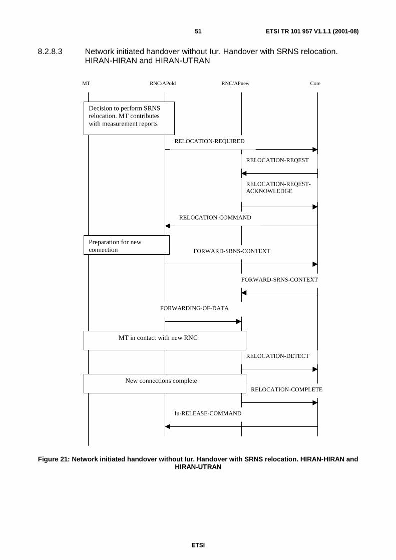
ETSI
ETSI TR 101 957 V1.1.1 (2001-08)51
8.2.8.3 Network initiated handover without Iur. Handover with SRNS relocation.HIRAN-HIRAN and HIRAN-UTRAN
MT RNC/APold RNC/APnew Core
RELOCATION-REQUIRED
RELOCATION-REQEST
RELOCATION-REQEST-ACKNOWLEDGE
RELOCATION-COMMAND
Decision to perform SRNSrelocation. MT contributeswith measurement reports
Preparation for newconnection FORWARD-SRNS-CONTEXT
FORWARD-SRNS-CONTEXT
FORWARDING-OF-DATA
MT in contact with new RNC
RELOCATION-DETECT
New connections completeRELOCATION-COMPLETE
Iu-RELEASE-COMMAND
Figure 21: Network initiated handover without Iur. Handover with SRNS relocation. HIRAN-HIRAN andHIRAN-UTRAN

ETSI
ETSI TR 101 957 V1.1.1 (2001-08)52
8.2.8.4 Network initiated handover with Iurhl2. HIRAN-HIRAN
MT RNC/APold RNC/APnew Core
RELOCATION-REQUIRED
RELOCATION-REQEST
RELOCATION-REQEST-ACKNOWLEDGE
Decision to perform SRNSrelocation. MT contributeswith measurement reports
RELOCATION-DETECT
RELOCATION-COMPLETE
Iu-RELEASE-COMMAND
RELOCATION-COMMIT
FORWARDING-OF-DATA
RNTI-REALLOCATION
RNTI-REALLOCATION COMPLETE
FORWARD-RELOCATION COMPLETE
FORWARD-RELOCATION COMPLETE-ACK
Iu-RELEASE-COMPLETE
Figure 22: Network initiated handover with Iurhl2. HIRAN-HIRAN
8.2.8.5 Mobile initiated handover without Iur. HIRAN-HIRAN and HIRAN-UTRAN
It is not solved for UMTS yet. It will be done so in the near future.

ETSI
ETSI TR 101 957 V1.1.1 (2001-08)53
8.2.8.6 Mobile initiated handover with Iur used. Combined cell/URA update andSRNS relocation. HIRAN-HIRAN
MT RNC/APold RNC/APnew CORE
CELL/URA-UPDATE. Instead, probablyparts of the HL2 HO procedure can be used.
CELL/URA-UPDATE. Instead, probablyparts of the HL2 HO procedure can be used.
RELOCATION-REQUIRED
RELOCATION-REQUEST
RELOCATION-REQUEST_ACKNOWLEDGE
RELOCATION-COMMAND
RELOCATION-COMMIT
Forwarding of data
RELOCATION-DETECT
CELL/URA-UPDATE-CONFIRM. InsteadProbably part of the HL2 HO procedure canbe used.
RNTI-REALLOCATION-COMPLETERELOCATION-COMPLETE
Iu-RELEASE-COMMAND
Iu-RELEASE-COMPLETE
Figure 23: Mobile initiated handover with Iur used. Combined cell/URA update and SRNS relocation.HIRAN-HIRAN

ETSI
ETSI TR 101 957 V1.1.1 (2001-08)54
8.2.9 Security
The security functions reside in the terminal, the access network and in the core network. The distribution of thefunctions differs and is described below.
(U)SIM based mutual authentication is used between the MT and the serving network. This requires that a physicaldevice, UICC(UMTS IC Card), is available in the terminal. The UMTS authentication method supports requirements 1,2 and 4 in clause 8.1.2.
Confidentiality of user traffic (requirement 6 in clause 8.1.2 is provided by the use of HIPERLAN/2 DES or TripleDESencryption. Encryption key management needs further study by BRAN. UMTS supports encryption between ME - RNCas there might be unprotected microwave links between Node B and RNC. It is assumed that HIPERLAN/2 accesspoints will have wired connections to an RNC/IWU. This means that the already included encryption in HIPERLAN/2could be sufficient. A threat analysis when having APs and the distribution network in a public environment should becarried out to verify the assumption about the encryption endpoint in the AP.
Authentication of data origin is required in requirement 3 in clause 8.1.2. This is supported in the same way as inUMTS. This means that the ability to encrypt PDU in a proper way is regarded as sufficient to assure the data origin.
Protection against modification of signalling, requirement 5 in clause 8.1.2 in UMTS requires the ME to support dataintegrity in the UMTS specified way. The UMTS data integrity protection method is also used for the signallingbetween the ME and the access network.
IMEI (International Mobile Equipment Identifier) is used to support terminal barring (requirement 7 in clause 8.1.2).
Quality of Service
The connection handling of HIPERLAN/2 RLC will be mapped with the Radio Access Bearer handling of the RANAPpart of Iuhl2. Additions have to be made to HIPERLAN/2 RLC and perhaps DLC to handle the parameters that is a partof, for example RAB assignment request. How to use the concepts "common channel" and "dedicated channel" forHIRAN need to be decided at some later stage.
9 ConclusionThe present document shows that HIPERLAN/2 - 3G Interworking can be achieved by changes, discussed within themain body of the document, to existing HIPERLAN/2 standards. It is therefore recommended that the findings of thepresent document are acted on and taken further.

ETSI
ETSI TR 101 957 V1.1.1 (2001-08)55
Annex A:List of figuresFigure 1: Loose Coupling interaction with Convergence sublayers ............................................................................. 13
Figure 2: Loose Coupling Architecture ...................................................................................................................... 14
Figure 3: Tight Coupling Architecture........................................................................................................................ 15
Figure 4: Void ........................................................................................................................................................... 19
Figure 5: (U)SIM centric system architecture ............................................................................................................. 20
Figure 6: Control plane (using HIPERLAN/2 user plane), authentication part ............................................................. 21
Figure 7: Control plane (using HIPERLAN/2 user plane), mobility part...................................................................... 21
Figure 8: User Plane .................................................................................................................................................. 22
Figure 9: Loose Coupling Interface Definitions.......................................................................................................... 22
Figure 10: The MT registers at a foreign network. ...................................................................................................... 27
Figure 11: Sequence diagram. The MT moves to a new AP connected to a new foreign agent. The black circlesdesignate the nodes that are affected by the expiration. ....................................................................................... 27
Figure 12: Logical encapsulation of HIPERLAN/2 within UTRAN ............................................................................ 29
Figure 13: Sequence diagram. The MT moves from UTRAN to HIPERLAN/2 while at the same time keeping the corenetwork attachment and the MIP registration. ..................................................................................................... 29
Figure 14: Sequence diagram. The MT moves from HIPERLAN/2 to UTRAN. It is still attached to UTRAN and theMIP registration is still there .............................................................................................................................. 30
Figure 15: Sequence diagram. The MT moves from HIPERLAN/2 to UTRAN. The UMTS MIP registration is not valid.......................................................................................................................................................................... 31
Figure 16: The control plane of Iu and Iuhl2. RANAP is placed in the radio network layer control plane..................... 37
Figure 17: The user plane of Iu and Iuhl2. Iu and Iuhl2 user planes are placed in the radio network layer user plane.GTP-U is the user plane of the GPRS Tunnelling Protocol.................................................................................. 38
Figure 18: The protocol stack of the control plane of Iur for UTRAN. This is not to imply that the solution should beused for HIRAN................................................................................................................................................. 39
Figure 19: Handover/Mobility Triggers...................................................................................................................... 49
Figure 20: An MT attaches (associates) to an UMTS network .................................................................................... 50
Figure 21: Network initiated handover without Iur. Handover with SRNS relocation. HIRAN-HIRAN andHIRAN-UTRAN................................................................................................................................................ 51
Figure 22: Network initiated handover with Iurhl2. HIRAN-HIRAN .......................................................................... 52
Figure 23: Mobile initiated handover with Iur used. Combined cell/URA update and SRNS relocation.HIRAN-HIRAN................................................................................................................................................. 53

ETSI
ETSI TR 101 957 V1.1.1 (2001-08)56
History
Document history
V1.1.1 August 2001 Publication