Embed Size (px)
Citation preview

Version 1.2 - August 2008
HARDWARE GUIDE
www.andor.com Andor Technology plc 2008

TABLE OF CONTENTS
iXonEM+ TABLE OF CONTENTS
Page 2
PAGE
SECTION 1 - INTRODUCTION 6
1.1 - TECHNICAL SUPPORT 6
1.2 - COMPONENTS 7 1.2.1 - Camera 7 1.2.2 - Controller Cards 8 1.2.3 - Controller Card Cables 9 1.2.4 - Cooler Power Supply Block 9 1.2.5 - Software 9
1.3 - SAFETY PRECAUTIONS & SAFE CAMERA OPERATION 10 1.3.1 - Care of the camera 10 1.3.2 - Environmental conditions 10 1.3.3 - Additional statement regarding equipment operation 10 1.3.4 - Overheating 10 1.3.5 - Working with electronics 11 1.3.6 - Condensation 11 1.3.7 - Dew Point graph 12 1.3.8 - EM Gain ageing 13 1.3.9 - Minimizing particulate contamination 14

TABLE OF CONTENTS
iXonEM+ TABLE OF CONTENTS
Page 3
PAGE
SECTION 2 - INSTALLATION 15
2.1 - INSTALLING THE HARDWARE 15 2.1.1 - PC requirements 15
2.2 - INSTALLING THE CONTROLLER CARD 16
2.3 - SMB CONNECTORS 18
2.4 - I2C CONNECTOR 18
2.5 - CONTROLLER CARD CONNECTOR 18
2.6 - COOLER POWER CONNECTOR 18
2.7 - WATER PIPE CONNECTORS 19
2.8 - CONNECTING THE SYSTEM 19
2.9 - MOUNTING POSTS 19
2.10 - OPTIONAL REMOTE CONTROL 20
2.11 - INSTALLING PCI DRIVER - WINDOWS OPERATING SYSTEMS (2000/XP/VISTA) 21 2.11.1 - Installing Linux driver 21 2.11.2 - Software installation 21
TABLE OF CONTENTS
iXonEM+ TABLE OF CONTENTS
Page 4
PAGE
SECTION 3 - HARDWARE FEATURES & FUNCTIONALITY 22
3.1 - EMCCD OPERATION 22 3.1.1 - Structure of an EMCCD 22 3.1.2 - EM Gain & Read Noise 24 3.1.3 - EM Gain ON vs EM Gain OFF 25 3.1.4 - Multiplicative Noise Factor & Photon Counting 27 3.1.5 - EM Gain dependence and stability 29 3.1.6 - RealGain
TM : Real and Linear gain 30
3.1.7 - EM Gain Ageing: What causes it and how is it countered? 31 3.1.8 - Gain & signal restrictions 32 3.1.9 - EMCAL
TM 32
3.2 - COOLING 33 3.2.1 - Cooling options 33 3.2.2 - Fan settings 33
3.3 - SENSOR READOUT OPTIMIZATION 34 3.3.1 - Sensor PreAmp options 35 3.3.2 - Variable Horizontal Readout Rate 37 3.3.3 - Variable Vertical Shift Speed 37 3.3.4 - Output amplifier selection 38 3.3.5 - Baseline Optimization 39
3.3.5.1 - Baseline Level and Baseline Offset 39 3.3.5.2 - Baseline Clamp 39
3.3.6 - Binning and Sub Image options 40
3.4 - ACQUISITION OPTIONS 42 3.4.1 - Capture Sequence in Frame Transfer Mode 42
3.4.1.1 - Points to consider when using FT Mode 43 3.4.2 - Capture Sequence in Non-Frame Transfer Mode with an FT CCD 44
3.4.2.1 - Points to note about using an FT CCD as a standard CCD 45 3.4.3 - Capture Sequence for Fast Kinetics with an FT CCD 46
3.4.3.1 - Points to consider when using Fast Kinetics mode 46 3.4.4 - Keep Clean Cycles 47
3.5 - TRIGGERING OPTIONS 50 3.5.1 - Triggering options in Frame Transfer (FT) mode 51
3.5.1.1 - Internal (FT) 51 3.5.1.2 - External (FT) 52 3.5.1.3 - External Exposure (FT) 54
3.5.2 - Triggering options in Non-Frame Transfer (NFT) mode 55 3.5.2.1 - Internal (NFT) 55 3.5.2.2 - External & Fast External (NFT) 56 3.5.2.3 - External Exposure (NFT) 58 3.5.2.4 - Software trigger (NFT) 59
3.5.3 - Trigger options in Fast Kinetics (FK) mode 60 3.5.3.1 - Internal (FK) 60 3.5.3.2 - External (FK) 61 3.5.3.3 - External Start (FK) 62
3.7 - SHUTTERING 63

TABLE OF CONTENTS
iXonEM+ TABLE OF CONTENTS
Page 5
PAGE
APPENDIX 64
A1 - EMCCD TECHNOLOGY 64 A1.1 - What is an Electron Multiplying CCD? 64 A1.2 - Does EMCCD technology eliminate Read Out Noise? 64 A1.3 - How sensitive are EMCCDs? 64 A1.4 - What applications are EMCCDs suitable for? 65 A1.5 - What is Andor Technology's experience with EMCCDs? 65
A2 - EMCCD SENSOR 66
A3 - VACUUM HOUSING 67 A3.1 - Thermoelectric cooler 68
A4 - OUTGASSING 69
A5 - CONTROLLER CARD PINOUTS 70
A6 - SMB SIGNAL DIAGRAMS 71
A7- MECHANICAL DIMENSIONS (860, 885 & 897 models) 72
A8- MECHANICAL DIMENSIONS (888 models) 73
A9 - TERMS & CONDITIONS 74
A10 - WARRANTIES & LIABILITY 75

INTRODUCTION
iXonEM+ SECTION 1
Page 6
SECTION 1 - INTRODUCTION
Thank you for choosing the Andor iXonEM
+. You are now in possession of a revolutionary new Electron
Multiplying Charge Coupled Device (EMCCD), designed for the most challenging low-light imaging applications.
This manual contains useful information and advice to ensure you get the optimum performance from your new
system. If you have any questions regarding your iXonEM
+ system, please feel free to contact Andor directly, or
via your local representative or supplier. You can find contact details below and on the next page.
1.1 - TECHNICAL SUPPORT
If you have any questions regarding the use of this equipment, please contact the representative* from whom
your system was purchased, or:
Europe USA
Andor Technology
7 Millennium Way
Springvale Business Park
Belfast
BT12 7AL
Northern Ireland
Tel. +44 (0)28 9023 7126
Fax. +44 (0)28 9031 0792
e-mail: [email protected]
Andor Technology
425 Sullivan Avenue - Suite 3
South Windsor
CT 06074
USA
Tel. +1 (860) 290-9211
Fax. +1 (860) 290-9566
e-mail: [email protected]
Asia-Pacific China
Andor Technology (Japan)
7F Ichibancho Central Building
22-1 Ichiban-Cho
Chiyoda-Ku
Tokyo 102-0082
Japan
Tel. +81-3-3511 0659
Fax. +81-3-3511 0662
e-mail: [email protected]
Andor Technology
Room 1116
Zhejiang Building
No. 26
An Zhen Xi Li
Section 3
Chaoyang District
Beijing 100029
China
Tel. +86-10-5129-4977
Fax. +86-10-6445-5401
e-mail: [email protected]
*NOTE: THE CONTACT DETAILS FOR YOUR NEAREST REPRESENTATIVE CAN BE FOUND ON OUR
WEBSITE

INTRODUCTION
iXonEM+ SECTION 1
Page 7
1.2 - COMPONENTS
The Andor iXonEM
+ system comprises the following main items:
• Detector head (hereinafter referred to as a Camera - see figure 1 below)
• 2 off BNC - SMB cables
• iXonEM
+ Hardware guide (this document)
• Software disk (SDK and/or Solis if ordered)
• Andor Programmer guide to Andor Basic (if ordered)
• Software Development Kit manual (if SDK ordered)
• System performance sheet
• ESD wrist strap. NOTE: This must be worn at all times when handling the PCI card
• PCI card (CCI-22, CCI-23 or CCI-24, camera model dependent)
• PCI controller card to camera cable
• Power supply block and correct power cable for the country where the camera is to be used
The following items are also available as optional accessories:
• Mounting Posts (see page 18)
• Remote control with Infrared receiver (see page 20)
1.2.1 - Camera
Figure 1: iXonEM
+ camera

INTRODUCTION
iXonEM+ SECTION 1
Page 8
1.2.2 - Controller Cards
Figure 2: CCI-22
Figure 3: CCI-23
Figure 4: CCI-24
The Controller cards (CCI-22, CCI-23 or CCI-24) buffer data from the camera, before transfer to the computer
memory, via the PCI bus. The CCI-22 & CCI-23 require a PCI 2.2 slot; the CCI-24 requires a PCIe x1 slot.
All boards are well shielded against electrical interference.
Your iXonEM
+ will be supplied with the controller card that is optimal for your camera model. Controller cards
have a 26-pin interface for connection via a cable to the PC and an auxiliary connector. The pin-outs for the
cards are shown on page 70.

INTRODUCTION
iXonEM+ SECTION 1
Page 9
1.2.3 - Controller Card Cables
The controller cards require the following connecting cables for correct operation:
Figure 5: PCI controller card to camera cable
Figure 6: Internal “Molex” connector cable
• The controller card connector cable is used to connect the camera to the PCI controller card.
• The power cable is connected within the computer between any available “Molex” connector and the
PCI controller card. NOTE: The internal power cable is wired to leave a free connector for
supplying power to other devices, should it be required.
1.2.4 - Cooler Power Supply Block
• The cooler Power Supply Block (PSB) is used to supply power to the Thermoelectric cooler within the
camera. A 2.1 mm Jack connector links the camera to the PSB.
NOTE: Cooling is only available when the PSB is connected to the camera.
1.2.5 - Software
Your iXonEM
+ may have been supplied with Andor Solis or Andor iQ software, or with the Andor SDK. However
it is also compatible with a range of 3rd
party software options offering optimized acquisition control and analysis
functionality. For further details of Andor software capabilities and software options, please go to the following
page on our website: http://www.andor.com/products/software/

INTRODUCTION
iXonEM+ SECTION 1
Page 10
1.3 - SAFETY PRECAUTIONS & SAFE CAMERA OPERATION 1.3.1 - Care of the camera
WARNINGS:
1. The camera is a precision scientific instrument containing fragile components. Always handle with the
care necessary for such instruments.
2. There are no user serviceable parts inside the camera. If the unit is opened, the warranty will be void.
1.3.2 - Environmental conditions
• Indoor use only
• Altitudes up to 5000m
• Storage temperature range -25ºC to 55ºC
• Operating Temperature range 5ºC to 30ºC
• Over-voltage category 1
• Pollution Degree 2
1.3.3 - Additional statement regarding equipment operation
IF THE EQUIPMENT IS USED IN A MANNER NOT SPECIFIED BY ANDOR TECHNOLOGY PLC, THE
PROTECTION PROVIDED BY THE EQUIPMENT MAY BE IMPAIRED.
1.3.4 - Overheating
Care should be taken to ensure that the camera does not overheat, as this can cause system failure.
Overheating may occur if either of the following situations arises:
• The air vents on the sides of the detector head are accidentally blocked or there is insufficient or no
water flow
• The ambient air temperature is higher than 30ºC.
To protect the camera from overheating, a thermal switch has been attached to the heat sink. If the temperature
of the heat sink rises above predefined limit, the power supply to the cooler will cut off and a buzzer will sound.
The cut-out will automatically reset once the head has cooled. It is not recommended that you operate in
conditions that would cause repeated cut-outs as the thermal switch has a limited number of operations.
NOTE: When using water cooling (see Hardware Manual for further details), always use water that is
above the dew point of the ambient environment otherwise condensation may occur (please see next
page).

INTRODUCTION
iXonEM+ SECTION 1
Page 11
1.3.5 - Working with electronics
The computer equipment that is to be used to operate the iXonEM
+ should be fitted with appropriate
surge/EMI/RFI protection on all power lines. Dedicated power lines or line isolation may be required for some
extremely noisy sites. Appropriate static control procedures should be used during the installation of the
system. Attention should be given to grounding. All cables should be fastened securely into place in order to
provide a reliable connection and to prevent accidental disconnection.
The power supply to the computer system should be switched off when changing connections between the
computer and the camera. The computer manufacturer’s safety precautions should be followed when installing
the PCI Controller Card into the computer.
The circuits used in the camera head and the PCI controller card are extremely sensitive to static electricity and
radiated electromagnetic fields and therefore they should not be used (or stored close to) EMI/RFI generators,
electrostatic field generators, electromagnetic or radioactive devices, or other similar sources of high energy
fields. Types of equipment that can cause problems include Arc welders, Plasma sources, Pulsed-discharge
optical sources, Radio frequency generators and X-ray instruments.
1.3.6 - Condensation
You may see condensation on the outside of the camera body if the temperature of the cooling water is too low
or if the water flow is too great. The first signs of condensation will usually be visible around the connectors
where the water tubes are attached. In such circumstances switch off the system and wipe the camera with a
soft, dry cloth. It is likely there will already be condensation on the cooling block and cooling fins inside the
camera. Please also carry out the following actions:
• Set the camera aside to dry for several hours before you attempt re-use
• Before re-use blow dry gas through the cooling slits on the side of the camera to remove any residual
moisture
• Use warmer water or reduce the flow of water when you start using the device again

INTRODUCTION
iXonEM+ SECTION 1
Page 12
1.3.7 - Dew Point graph
The graph below plots the relationship between Relative Humidity and Dew Point at varying ambient
temperature. This can be used to calculate the minimum temperature the cooling water should be set to.
Figure 7: Dew point graph
For example, when using an iXonEM
+ DU-897, you will need 10ºC cooling water to guarantee performance
down to -100ºC. In the relatively dry atmosphere of an air-conditioned lab, cooling water at 10ºC should not
present any problems.
However, in humid conditions (such as exist in some parts of the world) condensation may occur, resulting in
damage to the head. In such conditions you will have to use warmer water (20ºC or even higher if it is very
humid). The minimum CCD temperature would then be limited to a higher value.

INTRODUCTION
iXonEM+ SECTION 1
Page 13
1.3.8 - EM Gain ageing
It has been observed that some EMCCD sensors, more notably in cameras that incorporate L3Vision sensors
from E2V, are susceptible to EM gain fall-off over a period of time. It is important to note that this ageing effect
applies to any EMCCD camera manufacturer that incorporates L3Vision sensors into their cameras. In the
Andor iXonEM
+ range, this refers to the DU-897, DU-888 & DU-860 models.
EMCCD cameras incorporating Impactron (EMCCD) sensors from Texas Instruments have shown rates of
EMCCD saturation-induced ageing that are orders of magnitude slower than those with E2V sensors, exposed
to comparable light intensity and gain. NOTE: 885 iXonEM
+ models contain Impactron sensors from Texas
Instruments, which do not exhibit EM gain ageing (or at most exhibits it at a negligible level).
A technical note entitled: “Longevity in EMCCD and ICCD” , which further explains this phenomenon, can be
downloaded from the following website: http://www.andor.com/library/publications/?app=543
If left unchecked, this ageing phenomenon has the potential to significantly compromise the long-term
quantitative reliability of EMCCD cameras. Andor have recognized this ageing issue and have implemented
innovative measures to stabilize the EM gain on these sensors, ensuring that this ground-breaking ultra-
sensitive technology can deliver a prolonged quantitative service to the user and if these highly sensitive
sensors are used with due care and attention, ageing can be minimized and should not present any real
problem to the user.
More details of this ageing effect and Andor’s solutions can be found on page 31, but listed below are some
guidelines to minimize the EM gain ageing process:
• Do not use EM gain values greater than necessary to overcome the read noise. A rule of thumb is that
a gain of x4 or 5 the rms read noise (accessible from the spec sheet or performance sheet) is more
than sufficient to render this noise source negligible. In practice, this can always be achieved with EM
Gain of less than x300 (often much less). Pushing gain beyond this value would give little or no extra
Signal to Noise benefit and would only reduce dynamic range
• Only select the extended EM gain scale of x1000 for single photon counting applications and always
ensure that the signal falling onto the sensor is indeed within the regime of low numbers of photons per
pixel.
• Turn down the gain when the camera is not acquiring
• Try not to over-saturate the EMCCD sensor

INTRODUCTION
iXonEM+ SECTION 1
Page 14
1.3.9 - Minimizing particulate contamination
It is important that particulate contamination of the exterior of the camera window is kept to a minimum, such
that images are kept free of ‘shadowing’ particles directly in the focal path. The iXonEM
+ range comes equipped
with an internal C-mount shutter. Whilst not being required for frame transfer operation (which is a shutter-free
readout mode) it is good practice to close the shutter when the camera is not in acquisition use for a reasonable
period. It is also advisable to use the software to close the shutter when exposing the camera to the ‘open
environment’ (i.e. removed from a microscope C-mount or focusing lens) whilst power is still flowing to the
camera. When the camera power is turned off, the C-mount shutter closes automatically and the camera can be
moved freely. We recommend that the C-mount opening is covered when the camera is not in use.
If there is evidence of particulate contamination on the front window it is possible to clean the window by
blowing dry air gently over the window surface. However, the shutter has to be kept open for this procedure,
which means that the camera has to be powered up. Therefore since light can access the EMCCD sensor
during this time, we recommend that EM Gain is turned off, (readily selectable through the software).

INSTALLATION
iXonEM+ SECTION 2
Page 15
SECTION 2 - INSTALLATION 2.1 - INSTALLING THE HARDWARE 2.1.1 - PC requirements
The system requires a PCI compatible computer (PCI 2.2 for CCI-22 & CCI-23 cards or PCIe for the CCI-23
controller cards shown on page 8) and the minimum recommended PC specifications are as follows:
860, 888 & 897 Models
• 3 GHz Pentium Processor (or better)
• 1GB of RAM
• 10,000 rpm SATA hard drive preferred for extended kinetic series
• Windows 2000, XP or Vista operating system. Linux (SDK only)
• Available auxiliary internal power connector
• 32MB Hard Disc space
885 Models
• 3.2 GHz Pentium Processor (or better)
• 1GB of RAM
• SATA RAID 0 hard drive, e.g. .Seagate Barracuda, Western Digital Caviar RE or Raptor, etc.
• Windows 2000, XP or Vista operating system. Linux (SDK only)
• Available auxiliary internal power connector
• 25MB Hard Disc space
In all cases, the operating system should be on a separate hard drive and the hardware controller should be
on a separate PCI bus.

INSTALLATION
iXonEM+ SECTION 2
Page 16
2.2 - INSTALLING THE CONTROLLER CARD
The PCI Controller Card is installed in the same manner as you would fit most other slot-in cards such as
graphics cards. NOTE: Please consult the manual supplied with your computer to ensure correct
installation of the controller card for your particular model. We recommend you perform the installation
in a similar manner to the following:
1. Power down the computer and any accessories.
2. Unplug the computer and any accessories from the wall outlet(s).
3. Whilst observing appropriate static control procedures, unplug all cables from the rear of the computer.
4. Unscrew any cover mounting screws on the computer and set them aside safely.
5. Carefully remove the cover of the computer, e.g.:
6. Situated inside the computer are a number of Expansion Slots, e.g.:
7. After deciding which slot you are going to use, remove any metal filler bracket(s) that may be covering
the opening for the slot at the back of the computer. Place any retaining screw(s) and/or clip(s) in a safe
container, as you will need them later in the installation procedure.
8. At this point, put on the ESD wrist strap supplied with your camera and attach the crocodile clip
to a suitable earth point on the PC e.g.:
9. IMPORTANT NOTE: The ESD strap must be worn at all times when handling the Controller Card.
10. Remove the Controller Card carefully from its protective packaging

INSTALLATION
iXonEM+ SECTION 2
Page 17
11. Firmly press the connector into the chosen expansion slot, e.g.:
12. For maximum cooling, when the supplied PCI card has an Auxiliary Power connector (“flylead”), this
can be connected to a suitable point on the power supply of the PC, e.g.:
NOTE: Should any problems be experienced with this connection, please contact your nearest technical
representative.
13. Making sure that the card’s mounting bracket is flush with any other mounting brackets or filler brackets
to either side of it, secure the Controller Card in place.
14. Replace the cover of the computer and secure it with the mounting screws if applicable.
15. Reconnect any accessories you were using previously.

INSTALLATION
iXonEM+ SECTION 2
Page 18
2.3 - SMB CONNECTORS
Figure 8: iXonEM
+ connectors
There are four industry-standard SMB (Sub Miniature B) connectors fitted to the rear of the camera as shown
above. These are labelled as follows:
• Fire (please refer to pages 50 - 62)
• Shutter (see page 63)
• Arm (please refer to pages 50 - 62)
• Ext. Trig (External Trigger Input) - please refer to pages 50 - 62
These are used to send/receive Trigger and Fire signals. The SMB outputs (Fire & Shutter) are CMOS
compatible & series terminated at source (i.e. in the camera head) for a 50Ω cable.
NOTES:
1. The termination at the customer end should be high impedance (>1KΩ) as an incorrect
impedance match could cause errors with timing and triggering.
2. The External Trigger Input SMB is TTL level & CMOS compatible and has 470Ω impedance.
3. Signal diagrams of these connections can be found on page 71.
2.4 - I2C CONNECTOR
I2C: Philips
TM introduced the I
2C
TM bus 20 years ago and today it is the de facto standard for controlling and
monitoring applications in computing, communications and industrial segments. The pin-outs on the four-way
connector used on the iXonEM
+ are as follows:
Pin Function
1 I2C DATA
2 I2C
3 + 5V
4 GROUND
Figure 9: I2C connection (facing in) with pin-outs
2.5 - CONTROLLER CARD CONNECTOR
Controller: connection for the 26 pin interface between the camera and the PCI controller card.
2.6 - COOLER POWER CONNECTOR
Cooler Power: connection for the Power Supply Block (PSB) described on page 9.
SMB Connectors

INSTALLATION
iXonEM+ SECTION 2
Page 19
2.7 - WATER PIPE CONNECTORS
Two connectors are fitted to the camera in order to allow water cooling pipes to be connected, e.g.:
These can be connected to a water cooler or recirculator to improve cooling.
2.8 - CONNECTING THE SYSTEM
Connect the elements of your system as follows:
1. Wherever possible, plug your PC into the mains outlet to ensure grounding, but keep the power
switched off.
2. Connect the Camera to the Controller Card using the Cable provided. It is important that this cable is
securely fastened to provide a good grounding between the camera and Controller Card.
3. Your system has been supplied with a PSB for cooling. The PSB connects to the camera via a 2.1mm
Jack plug and to the mains electricity supply with a standard plug for your location.
4. There is only one socket on the camera that the PSB can be connected to and this is labeled Cooler
Power (please see figure 8 on page 18).
5. For best performance the PSB should be plugged into the same power source as the computer.
2.9 - MOUNTING POSTS
• Mounting posts can be fitted on three sides of the camera. These can be used to mount the camera if
the C-Mount is not used, and/or to mount accessories. NOTE:.A bag containing two Ø1/2" x 80mm
long x 1/4-20 UNC posts is included with all kits
• There are 3 pairs of holes for the mounting posts, each with 2.0" spacing.
Figure 10: Mounting post installation
INSTALLATION
iXonEM+ SECTION 2
Page 20
2.10 - OPTIONAL REMOTE CONTROL
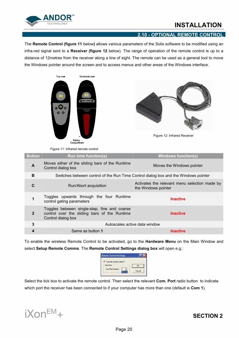
The Remote Control (figure 11 below) allows various parameters of the Solis software to be modified using an
infra-red signal sent to a Receiver (figure 12 below). The range of operation of the remote control is up to a
distance of 12metres from the receiver along a line of sight. The remote can be used as a general tool to move
the Windows pointer around the screen and to access menus and other areas of the Windows interface.
Figure 11: Infrared remote control
Figure 12: Infrared Receiver
Button Run time function(s) Windows function(s)
A Moves either of the sliding bars of the Runtime Control dialog box
Moves the Windows pointer
B Switches between control of the Run Time Control dialog box and the Windows pointer
C Run/Abort acquisition Activates the relevant menu selection made by the Windows pointer
1 Toggles upwards through the four Runtime control gating parameters
Inactive
2 Toggles between single-step, fine and coarse control over the sliding bars of the Runtime Control dialog box
Inactive
3 Autoscales active data window
4 Same as button 1 Inactive
To enable the wireless Remote Control to be activated, go to the Hardware Menu on the Main Window and
select Setup Remote Comms. The Remote Control Settings dialog box will open e.g.:
Select the tick box to activate the remote control. Then select the relevant Com. Port radio button to indicate
which port the receiver has been connected to if your computer has more than one (default is Com 1).

INSTALLATION
iXonEM+ SECTION 2
Page 21
2.11 - INSTALLING PCI DRIVER - WINDOWS OPERATING SYSTEMS (2000/XP/VISTA)
During the start up sequence the operating system will detect the Andor PCI controller card and a dialogue box
will prompt you for the location of the device driver.
• Insert the CD containing the driver file. With Andor Solis or iQ software, this is located on the main
application CD. 3rd party software packages may supply a separate driver installation CD containing
the Andor drivers. Navigate to the Setup Information File (atmcd.inf).
• Select the device driver file and click OK.
• Restart the PC. This completes the device driver installation.
• The Andor Technology PCI driver should now be shown in the Device Manager, e.g.:
2.11.1 - Installing Linux driver
The Andor PCI controller card device driver is compiled from source and installed automatically during
installation of the Andor Linux SDK using the install_andor script.
2.11.2 - Software installation
For detailed instructions on how to install the program software, please refer to the software manual supplied
with your camera.

HARDWARE FEATURES & FUNCTIONALITY
iXonEM+ SECTION 3
Page 22
SECTION 3 - HARDWARE FEATURES & FUNCTIONALITY 3.1 - EMCCD OPERATION
3.1.1 - Structure of an EMCCD
Advances in sensor technology have led to the development of a new generation of ultra-sensitive, low light
Electron Multiplying Charged Coupled Devices (EMCCDs). At the heart of your iXonEM
+ camera is the latest
EMCCD, a revolutionary technology, capable of single photon detection. An EMCCD is a silicon-based
semiconductor chip bearing a two-dimensional matrix of photo-sensors or pixels. This matrix is usually referred
to as the image area. The pixels are often described as being arranged in rows and columns, the rows running
horizontally and the columns vertically. The EMCCD in the camera is identical in structure to a conventional
Charged Coupled Device (CCD) but with the shift register extended to include an additional section, the
Multiplication or Gain Register as shown in figure 13 below:
Figure 13: EMCCD structure

HARDWARE FEATURES & FUNCTIONALITY
iXonEM+ SECTION 3
Page 23
During an acquisition using a conventional Frame Transfer CCD (FT CCD), the image area is exposed to light
and an image is captured. This image in the form of an electronic charge is then automatically shifted
downwards behind the masked region of the chip before being read out. To read out the sensor, charge is
moved vertically into the readout register, and then horizontally from the readout register into the output node of
the amplifier. As stated on the previous page, the readout register is extended to include the multiplication
(gain) register. The amplification occurs in this register through the scheme highlighted below in figure 14.
When moving charge through a register there is a very tiny but finite probability that the charges being
transferred can create additional charge by a process known as “impact ionization”. Impact ionization occurs
when a charge has sufficient energy to create another electron-hole pair and hence a free electron charge in
the conduction band can create another charge. Hence, amplification occurs. To make this process viable,
EMCCD’s tailor the process in two ways, as follows:
1. Firstly, the probability of any one charge creating a secondary electron is increased by giving the initial
electron charge more energy. This is typically done by replacing one of the electrodes (phases) of this
readout section with two electrodes. The first is held at a fixed potential and the second is operated as
normal, except that much higher voltages are employed than are necessary for charge transfer alone.
The large electric field generated between the fixed voltage electrode and the clocked electrode is
sufficiently high for the electrons to cause “impact ionization” as they transfer. The impact ionization
causes the generation of new electrons, i.e. multiplication or gain.
2. Secondly, the EMCCD is designed with hundreds of cells or pixels in which impact ionization can occur
and although the probability of amplification or multiplication in any one pixel is small (only around x1.01
to x1.015 times) over the entire length of the EM register the probability is very high and substantial
gains of up to thousands can be achieved.
Figure 14: Gain register operation
HARDWARE FEATURES & FUNCTIONALITY
iXonEM+ SECTION 3
Page 24
3.1.2 - EM Gain & Read Noise
As explained on the previous pages, EMCCD sensors allow the detected signal to be amplified on the actual
sensor itself before being readout through the output amplifier and digitized by the Analog to Digital (A/D)
converter. The reason that this on-chip-multiplication process gives such a spectacular improvement in low light
detection is that it negates the effect of any electronic noise that may be generated by the read out electronics.
All CCD cameras have an associated minimum electronic noise floor which is often termed the Read Noise of
the system. Read noise is produced during the readout process mostly by the output amplifier but also has
contributions from the digitization electronics. This sets the minimum signal level that can be detected by the
camera, as any signal level below the read noise level will be indistinguishable from the read noise itself.
Read noise has therefore been the major limiting factor for low light level detection in CCDs for many years until
the introduction of EMCCD cameras by Andor Technology in 2000. By applying EM gain, a weak signal that
would otherwise be indistinguishable from the read noise can be amplified above the read noise level and thus
be read out as a useful signal. This amplification of the signal before being read out effectively reduces the read
noise level of the camera and even at relatively modest EM gain settings the effective read noise can be
reduced to less than 1 electron r.m.s.
One other point to note is that since read noise increases with increased readout rate the application of EM gain
really comes into its own at higher readout rates as any increase in the read noise can be overcome simply by
increasing the EM gain. For example, an iXonEM
+ DU-897 typically has a read noise of 50 electrons rms when
reading out at 10MHz. This can easily be reduced to < 1 electron by applying > x50 EM gain.

HARDWARE FEATURES & FUNCTIONALITY
iXonEM+ SECTION 3
Page 25
3.1.3 - EM Gain ON vs EM Gain OFF
Figure 15 below shows Signal to Noise (S/N) plots derived from the specifications of the back-illuminated
iXonEM
+ EMCCDs, read out at 10MHz for a photon wavelength at which the Quantum Efficiency (QE) of the
sensor is assumed to be 90%. Such plots are very useful to gauge at what signal intensity it becomes
appropriate to use EM Gain to increase S/N.
It is clear that at 10MHz readout, one needs to encounter relatively intense signals of > 2900 photons / pixel
before it becomes advantageous to operate with EM Gain off. Note that the “ideal” curve represents a pure
Signal to Shot Noise ratio and is shown for reference – if the camera had no sources of noise, this is what the
curve would appear like. Even with EM Gain turned on we encounter uniformly lower signal to noise than the
ideal curve. This is due to the influence of Multiplicative Noise, which has the effect of increasing the shot noise
by a factor of 2 or ~1.41.
Figure 15: EM Gain ON vs. EM-Gain OFF signal to noise plots for back-illuminated iXonEM
+ EMCCDs at 10MHz readout speed (applies to
DU-897, DU-860 and DU-888 models).

HARDWARE FEATURES & FUNCTIONALITY
iXonEM+ SECTION 3
Page 26
Figure 16 below shows S/N plots derived from the specifications of the back-illuminated iXonEM
+ EMCCDs at
1MHz (slower frame rate operation), read out either with EM Gain ON or alternatively through the conventional
amplifier (i.e. standard CCD operation). Again, this plot assumes a photon wavelength at which the QE of the
sensor is 90%. Specifically this figure applies to DU-897 and DU-888 models where the user has the choice of
either EMCCD or conventional amplifiers.
At these slower speed operations when one has the choice to read out as a “conventional” CCD it can often
be advantageous to do so in order to achieve better signal to noise. Indeed the plots show that the cross-over
point is at ~42 photons/pixel, below which it is still advised to readout through the EM amplifier with Gain
applied.
Figure 16: EM Gain ON vs. Conventional Amplifier signal to noise plots for back-illuminated iXonEM
+ EMCCDs at 1MHz readout speed
(applies to DU-897 and DU-888 models).

HARDWARE FEATURES & FUNCTIONALITY
iXonEM+ SECTION 3
Page 27
3.1.4 - Multiplicative Noise Factor & Photon Counting
It is impossible to know the exact gain a detected signal charge traversing the EM gain register will acquire due
to the stochastic nature of the processes which produce EM gain. However it is possible to calculate the
probability distribution function of output charge for a given input charge.
At reasonably high gain levels (>30) this uncertainty introduces an additional noise component called
Multiplicative Noise. This noise source is only present in signal amplifying technologies and is a measure of
the uncertainty inherent to the signal multiplying process. For example, during each transfer of electrons from
element to element along the gain register of the EMCCD, only a small probability exists that the process of
impact ionization will produce an extra electron during that step. This happens to be a small probability but
when executed over > 590 steps, a very large overall EM gain results. However, the downside to this process
results from the probabilities! Due to this, there is a statistical variation in the overall number of electrons
generated by the gain register from an initial charge packet. This uncertainty is quantified by a parameter
called “Noise Factor” and detailed theoretical and measured analysis has placed this Noise Factor at a value
of 2 (or 1.41:1) for EMCCD technology. Note: This noise source is significantly greater for the Multi
Channel Plate (MCP) of ICCDs than for the gain register of the EMCCD. ICCDs have noise factors
typically ranging from 1.5 to >2.
So, this is an additional form of noise that must be taken into account when calculating Signal/Noise for these
detectors. However, one way to better understand the effects of this noise source is in terms of an addition to
the shot noise of the system. Extra multiplicative noise has the same form as shot noise in that each noise type
results in an increase in the variation of number of electrons that are read out of the sensor (under constant
uniform illumination).

HARDWARE FEATURES & FUNCTIONALITY
iXonEM+ SECTION 3
Page 28
Indeed, multiplicative noise can be thought to contribute directly to the overall shot noise, in that one should
multiply the Shot Noise by the Noise Factor when calculating overall noise. Simply put, multiplicative noise
does not in any way reduce the average signal intensity or reduce the number of photons that are detected, it
simply increases the degree of variation of the signal around the mean value, in addition to the variation that
already exists from the shot noise (variation from pixel to pixel or from frame to frame). This additional variation
to the signal intensity is represented pictorially below in figure 17 as a signal intensity profile.
Figure 17: Signal intensity profile
In the limit of when there is less than 1 electron falling on a pixel in a single exposure, the EMCCD can be used
in Photon Counting Mode. In this mode a threshold is set above the ordinary amplifier readout and all events
are counted as single photons. In this mode, with a suitably high gain, a high fraction of the incident photons
(>90%) can be counted without being affected by the Noise Factor effect.

HARDWARE FEATURES & FUNCTIONALITY
iXonEM+ SECTION 3
Page 29
3.1.5 - EM Gain dependence and stability
EM gain is a function of the EM voltage and of the sensor operating temperature. When the user applies gain
through the software, it is the EM voltage in the gain register that is varied. As can be seen from figure 18
below, the dependence of EM gain on EM voltage is sharp (note the logarithmic scaling). This arises because
the signal electrons acquire energy as they are accelerated through the EM electric field, and once this field
strength reaches the threshold needed to overcome the bandgap energy, the impact ionization rate rises
rapidly. This sharp dependence has meant that the software control of EM gain in all EMCCD cameras to date
has been via a non-linear scale, with most of the amplification occurring within a relatively small portion at the
top of the overall scale. Thus considerable fine tuning by the user to determine an optimal gain setting has been
required and even then the actual gain is determined only through measurement of a stable light source, with
and without gain applied.
Figure 18: EM gain vs EM clock voltage
Figure 19 shows how the EM gain varies with temperature, this dependence arising primarily from photon
scattering of electrons when they are accelerating in the EM electric field. The scattering causes a loss of
energy, which increases with temperature. To make up this loss and maintain EM gain, a larger EM electric field
must be used at higher temperatures. As can be seen from Figure 18, EM gains well in excess of x1000 can be
achieved at low temperatures. However it is not recommended that gains above x1000 be used because such
high gains can cause significant ageing of the gain register (see EM Gain Ageing on page 13).
Figure 19: EM gain vs sensor cooling temperature

HARDWARE FEATURES & FUNCTIONALITY
iXonEM+ SECTION 3
Page 30
3.1.6 - RealGainTM
: Real and Linear gain
Through a detailed analysis of the complex EM voltage dependence Andor have successfully converted the
relationship between EM gain and the EM clock voltage setting into a linear one. Importantly, the actual EM
gain can be selected directly from a linear scale displayed in software. No more guesswork with arbitrary gain
units on a non-linear scale - the gain you ask for is the gain you get.
Select the best gain to overcome noise and maximize dynamic range. Also, although EM gain is temperature
dependent, Andor’s linear and real gain calibration extends to any EMCCD cooling temperature. Selecting x300
EM gain @ -50°C, or at -100°C gives the same x300 actual gain! This delivers a new benchmark of simplicity
and ease of operation to the user and sets a new precedent in what should be expected from EMCCD
technology.

HARDWARE FEATURES & FUNCTIONALITY
iXonEM+ SECTION 3
Page 31
3.1.7 - EM Gain Ageing: What causes it and how is it countered?
As already noted in the discussion on safe camera operation in Section 2, EMCCD sensors can suffer from EM
gain ageing. This is the phenomenon whereby the EM gain falls off over a period of time when operating at the
same clock voltage and cooling temperature. This ageing effect appears to be dependent on the amount of
charge that is passed through the gain register, combined with the actual EM electric field strength that it is
transferred through. It seems to be very strongly dependent on the EM electric field strength. Therefore when
operating at high EM gains the ageing rate can be disproportionately greater. Fortunately, it has been observed
that this ageing effect itself decreases with time, meaning that with proper use the device should remain useful
for many years. As part of Andor’s EMCCD production process all sensors are exposed to conditions that
results in much of the “shorter-term ageing” having already occurred prior to calibration and setting of the EM
gain.
The explanation for this ageing effect is not fully understood, but it is assumed that accelerating charge through
the high electric fields is causing a tiny fraction of that charge to become permanently embedded in the
insulator (typically silicon dioxide) between the EM electrode and the active silicon. This slow build-up of charge
effectively reduces the field strength produced by the electrode. The signal electrons therefore experience a
lower accelerating potential which subsequently produces fewer secondary electrons from the impact ionisation
process resulting in less electron multiplication and, in effect, a lower EM gain.
In order to minimise the effect of EM gain ageing it is recommended that the following guidelines are always
adhered to:
• Do not use EM gains greater than necessary to overcome the read noise (please refer to figure 15 on
page 25 and figure 16 on page 26). A rule of thumb is that a gain of x4 or 5 the root-mean-square read
noise (accessible from the performance sheet) is more than sufficient to render this noise source
negligible. In practice, this can always be achieved with EM Gain of less than x300 (often much less).
Pushing gain beyond this value would give little or no extra S/N benefit and would only reduce dynamic
range.
• Only select the extended EM gain scale of x 1000 when single photon counting and always ensure
that the signal falling onto the sensor is indeed within the regime of low numbers of photons per pixel.
• Turn the EM gain OFF when not in use.
• Try not to over-saturate the EMCCD detector.
For simplicity and ease of use many of these guidelines have been uniquely woven into the iXonEM
+ systems, to
make it difficult for the user to step outside of them and unwaringly cause accelerated sensor ageing. This
defence is two pronged, and makes heavy use of Andor’s linear and quantitative gain calibration scale
(RealGainTM
) described above.

HARDWARE FEATURES & FUNCTIONALITY
iXonEM+ SECTION 3
Page 32
3.1.8 - Gain & signal restrictions
Part of the measures taken has been to invoke temperature compensated real gain limits, coupled with signal
intensity feedback (after EM amplification). This ensures that the user is unable to apply excessive gain and/or
signal, any more than is necessary to render the read noise floor negligible for a given signal intensity and
readout speed. Secondly, when not actually acquiring data, for example, during “keep clean” cycles or when
outside a selected sub-image area, Andor EMCCDs have been internally configured to prevent any unwanted
signal entering the EM gain register. Together these measures ensure that the rate of EM gain ageing is
significantly reduced.
3.1.9 - EMCALTM
Andor have developed, in the iXonEM
+, a unique and patented method of user-initiated EM gain self
recalibration - EMCALTM
. This is available only in iXonEM
+ camera that contain L3 vision sensors from E2V, i.e.
DU-897 and DU-888 models. The 885 range of iXonEM
+ cameras contain sensors from Texas Instruments that
show negligible levels of gain ageing, and thus the EMCALTM
function is not required.
Thus for the L3Vision based cameras, even after exercising due care during usage and availing of the above
internal restrictions, the EM gain will gradually decrease over an extended period of time. This reduction in EM
gain can be rectified by using the EMCALTM
self recalibration process which is very easily initiated by the user.
Check on-line for the latest EMCALTM
routine.
This process uses the iXonEM
+ in-built temperature compensated linear gain scales to reset the EM gain
calibration to reflect the true values requested on the software scale, in reality giving RealGainTM
values and
thus markedly prolonging the operational lifetime and quantitative reliability of the technology, and
circumventing the need to return to the factory for recalibration. To the user, this means optimal signal to noise
ratio, maximum dynamic range and prolonged system longevity.

HARDWARE FEATURES & FUNCTIONALITY
iXonEM+ SECTION 3
Page 33
3.2 - COOLING
The EMCCD sensor is cooled using a Thermoelectric (TE) cooler. TE coolers are small electrically powered
devices with no moving parts, making them reliable and convenient. A TE cooler is actually a heat pump, i.e. it
achieves a temperature difference by transferring heat from its “cold side” (the EMCCD sensor) to its “hot side”
(the built-in heat sink). Therefore the minimum absolute operating temperature of the EMCCD depends on the
temperature of the heat sink. Andor’s vacuum design means that we can achieve minimum cooling
temperatures unrivalled by other manufacturers. The maximum temperature difference that a TE device can
attain is dependent on the following factors:
• Heat load created by the CCD
• Number of cooling stages of the TE cooler
• Operating current
3.2.1 - Cooling options
The heat that builds up on the heat sink must be removed and this can be achieved in one of the two following
ways:
1. Air cooling: a small built-in fan forces air over the heat sink
2. Water cooling: external water is circulated through the heat sink using the water connectors on the
head and this can take one of the following forms:
• Recirculation
• Chilling
All Andor iXonEM
+ systems support both cooling options. Whichever method is being employed, it is not
desirable for the operating temperature of the CCD simply to be dependent on, or vary with, the heat sink
temperature. Therefore, a temperature sensor on the CCD (combined with a feedback circuit that controls the
operating current of the cooler) allows stabilization of the CCD to any desired temperature within the cooler
operating range.
3.2.2 - Fan settings
The speed of the cooling fan can also be controlled, useful if working in experimental configurations which are
extremely sensitive to vibration. The vast majority of applications, including optical microscopy, can be used
with the default highest fan speed, since the vibrations from the fan are minimal. However, some applications
can be extremely sensitive to even the smallest of vibrations (such as when combining an optical set-up with
patch clamp electrophysiology or atomic force microscopy) and it can be useful to either select a slower fan
speed, or to temporarily turn off the fan altogether, for the duration of the acquisition.
If the fan is being turned off altogether, depending on the cooling temperature selected and on the ambient
temperature, the acquisition duration can be as long as 15 - 20 minutes before temperature begins to rise. The
fan must then be turned on again to give the head time to re-stabilize (dissipate built-up excess heat from the
Peltier TE cooler) before the next acquisition is begun.
NOTE: If water cooling is being used, the fan can be turned off and exceptional cooling performance
maintained indefinitely.

HARDWARE FEATURES & FUNCTIONALITY
iXonEM+ SECTION 3
Page 34
3.3 - SENSOR READOUT OPTIMIZATION
To allow the camera to be optimized for the widest range of applications it is important to have flexibility in the
readout options available, some of these include:
• Cooling (please see page 33)
• Sensor preamp settings
• Variable horizontal readout rate
• Variable vertical shift speed
• Output amplifier selection
• Baseline settings
• Binning and sub image settings
These options and an explanation of how to optimize them are explained on pages 35 - 41.

HARDWARE FEATURES & FUNCTIONALITY
iXonEM+ SECTION 3
Page 35
3.3.1 - Sensor PreAmp options
An EMCCD sensor can have a much larger dynamic range than can be faithfully reproduced with the
Analogue/Digital converters and signal processing circuitry currently available on the market today. To
overcome this shortcoming and access the range of signals from the smallest to the largest and to optimize the
camera performance it is necessary to allow different pre-amplifier gain settings. However, it is only ever
recommended selecting something other than the default highest PreAmp (most sensitive) setting for
applications that are extremely challenged by dynamic range concerns. It is very important, however, that for
such high-dynamic range applications, the user applies even more care to the amount of EM gain applied (high
EM gain can drastically reduce the true dynamic range of the camera). Ideally, for maximum dynamic range
whilst maintaining improved Signal to Noise (S/N), the EM gain setting should be set equal to the read noise at
the readout speed selected (value obtainable from the performance sheet that comes with the delivered
system).
Pre-amplifier gain selection in CCDs is traditionally used to trade off S/N vs dynamic range. A higher PreAmp
setting means fewer electrons/count, resulting in a lower system noise floor, therefore a higher S/N. However,
high PreAmp settings may not match well to the pixel well depth of the sensor, therefore a lower setting can be
selected to meet the full well depth potential, e.g. a PreAmp setting yielding 1.5 e-/count may be selected to
ensure that the 65536 digitization levels of a 16-bit A/D is closely matched to a 100,000 e- pixel well depth. A
PreAmp setting of 1 e-/count, while giving a lower noise floor, would not harness the full 100,000 e
- well depth.
The situation is not nearly as straightforward for EMCCDs because:
1. EM gain overcomes readout noise and amplifies signals relative to the digitization noise (which is fixed
for a given PreAmp setting).
2. Gain register pixels have a greater well depth than the imaging pixel well depth
The latter point can be particularly confusing and indeed has led to confusion in the field. What this has meant
is that we have set some of the lower pre-amp settings associated with the EM-output to match the extended
well capacity of the gain register pixels (as reported by the sensor manufacturers E2V or TI). This means that
these pre-amp settings are designed to be used with EM Gain! Otherwise, the lower well capacity of the
imaging pixels will saturate long before the A/D. This is why some users have been confused at not being able
to reach the full ~16k counts of the 14-bit A/D channel, when they hadn’t applied EM Gain.

HARDWARE FEATURES & FUNCTIONALITY
iXonEM+ SECTION 3
Page 36
Basically, Andor recommend using the default highest value PreAmp setting (e.g. x4.8 setting of the iXonEM
+
DU-897E giving ~ 11.3 e-/count @ 10MHz) for most low-light applications. Most genuinely low light applications
are not limited by well capacity, as long as sensible EM gain settings are applied (we recommend not
exceeding x300 EM gain, except for single photon counting experiments). At this highest PreAmp setting, the
14-bit A/D would saturate @ 16,380 x 11.3 e-/count = 180,800 e
-. In our opinion, this is a resaonable range to
cover the majority of low light measurements. For example, with an EM gain of x300 (RealGainTM
), it would take
600 electrons in a pixel of the sensor to reach this A/D saturation limit. Say the QE is 80% at the wavelength of
interest then this corresponds to maximum of 750 photons falling onto that pixel. That is perfectly satisfactory
dynamic range for the vast majority of low light imaging applications.
The core reason for us wishing to recommend this PreAmp setting, even over the middle (~x2.4) PreAmp
setting, is that it implements an additional restriction as to how much charge is allowed to build up in the sensor.
This in turn will help minimize the rate of EM gain ageing (please see page 31 for further details on measures
against gain ageing). However, some applications can be very demanding of dynamic range, and for those we
recommend using a lower PreAmp setting such as x2.4. This will ensure the A/D capacity is more closely
matched to the well capacity of the gain register pixels, thus affording maximum dynamic range. Also as
mentioned above, to maximize the true dynamic range of the camera we recommend tuning the RealGainTM
gain setting to a value close to the value of the readout noise at the selected readout speed (e.g. if readout
noise is ~ 50 electrons @ 10 MHz, set the EM gain to x50 for maximum dynamic range).

HARDWARE FEATURES & FUNCTIONALITY
iXonEM+ SECTION 3
Page 37
3.3.2 - Variable Horizontal Readout Rate
The Horizontal Readout Rate defines the rate at which pixels are read from the shift register. The faster the
horizontal readout rate the higher the frame rate that can be achieved. The ability to change the pixel readout
speed is important to achieve the maximum flexibility of camera operation, particularly in terms of dynamic
range. Slower readout typically allows lower read noise and higher available dynamic range, but at the expense
of slower frame rates. There are number of different horizontal readout rates available on all iXonEM
+ models.
Please refer to the performance sheet for readout rates available on your particular model.
3.3.3 - Variable Vertical Shift Speed
The vertical shift speed is the time taken to vertically shift all pixels one row down, with the bottom row entering
the shift register. The ability to vary the vertical shift speed is important for several reasons. It is possible using
the different vertical speeds to better synchronize the frame rates to external events such as a confocal
spinning disc. Faster vertical shift speeds also have benefits such as lower Clock Induced Charge (CIC). A
drawback with faster vertical shift speeds is that the charge transfer efficiency is reduced, effectively reducing
the pixel well depth. This is particularly important for bright signals as a pixel with a large signal is likely to have
some charge left behind if the vertical shift speed is too fast. This will result in degraded spatial resolution.
Slower vertical clocks ensure better charge transfer efficiency giving maximum pixel well depth but result in a
slower maximum frame rate. To improve the transfer efficiency the clocking voltage can be increased using the
vertical clock voltage amplitude setting. However, the higher the voltage, the higher the clock-induced charge.
Thus the user must make a measured judgement as to which setting works best for their situation, for example:
• For low CIC: Use the fastest vertical shift speed that still transfers charge correctly (no image
distortion), without having to select excess vertical shift voltage amplitude
• For maximum pixel well depth: Use the slowest vertical shift speed, which will give an increase in
CIC
• For maximum frame rate: Use the fastest vertical shift speed and increase the vertical shift voltage
amplitude to the minimum value that regains the full pixel well depth.
• To reduce vertical smearing during very short exposure: use a faster vertical shift speed. This
vertical smearing is due to the fact that light is still falling on the image area during the short time taken
to transfer the charge from the image area into the storage area. If the actual exposure time is of a
similar magnitude to this transfer time then as pixels are shifted vertically through brighter regions of the
image they will collect “extra” charge which will manifest itself as vertical streaking. NOTE: For
extremely short exposure times, a fast external shutter or pulsed light source may be required.
• For short exposures (e.g. 1ms): with high signal count and DC illumination, it may be necessary to
increase the vertical clock voltage to ensure that the keep clean cycle can fully remove the extremely
high (saturated) signal that may have accumulated during the sensor readout phase.

HARDWARE FEATURES & FUNCTIONALITY
iXonEM+ SECTION 3
Page 38
3.3.4 - Output amplifier selection
A number of the EMCCD sensors in the iXonEM
+ range have dual output amplifiers, an electron multiplying
output amplifier and a conventional output amplifier. This increases the versatility of the camera as the EM
amplifier can be selected for fast imaging in low light conditions whilst the conventional amplifier can be
selected where more light is available and a slower readout with its associated lower read noise and higher
dynamic range is preferred.
Figure 20 below details schematically the readout structure on sensors with both output amplifiers present.
From this it can seen that when reading out through the EM amplifier accumulated charge will move to the right
along the serial register and then into the EM gain register. When the conventional output amplifier is selected
the charge to be read out will move along the serial register to the left then be transferred directly into the
conventional output amplifier. This change in direction has the effect of producing mirror images when
comparing raw data from the two output amplifiers. Some software packages will automatically reverse the
image orientation of one of the output amplifiers to allow direct comparison of images. The user should consult
their software manual to verify if this is the case.
Figure 20: Sensor readout structure

HARDWARE FEATURES & FUNCTIONALITY
iXonEM+ SECTION 3
Page 39
3.3.5 - Baseline Optimization 3.3.5.1 - Baseline Level and Baseline Offset
The baseline or bias level is an electronic offset added to the output signal from the EMCCD sensor to ensure
that the displayed signal level is always a positive number of counts. This baseline level often tends to increase
with decreasing sensor cooling temperature. For all iXonEM
+ cameras it is factory calibrated to approximately
400 counts at a cooling temperature of -75°C.
NOTES:
• At warmer temperatures the baseline level will decrease and may move below zero resulting in a
signal of zero counts being displayed. This can be overcome either by moving to a lower
cooling temperature or by using the baseline offset option which adds up to 1000 counts to the
baseline level.
• Conversely at colder temperatures than the calibration temperature the baseline may increase
slightly and this can be countered by using the baseline offset option to subtract up to 1000
counts from the baseline level.
3.3.5.2 - Baseline Clamp
When acquiring data small changes in the ambient temperature and/or in the heat generation of the driving
electronics within the camera may cause some drift in the baseline level. This is most often observed during
long kinetic series.
Any drift in the baseline level can be corrected by using the Baseline Clamp option. Baseline Clamp corrects
each individual image for any baseline drift by subtracting an average bias signal from each image pixel and
then adding 100 counts to ensure that the displayed signal level is always a positive number of counts.
NOTE: Before activating Baseline Clamp, please ensure that the baseline level is above zero counts for
the cooling temperature selected.

HARDWARE FEATURES & FUNCTIONALITY
iXonEM+ SECTION 3
Page 40
3.3.6 - Binning and Sub Image options
Binning is a process that allows charge from two or more pixels to be combined on the EMCCD-chip prior to
readout. Summing charge on the EMCCD and doing a single readout gives better noise performance than
reading out several pixels and then summing them in computer memory. This is because each act of reading
out contributes to noise. There are two types of the binning as follows:
• Vertical Binning: Where charge from two or more rows of the EMCCD-chip are moved down into the
shift register before the charge is read out. The number of rows shifted depends on the binning pattern
selected. Thus, for each column of the EMCCD-chip, charge from two or more vertical elements is
summed into the corresponding element of the shift register. The charge from each of the pixels in the
shift register is then shifted horizontally to the output amplifier and read out.
• Horizontal Binning: Where charge from two or more pixels in the serial register are transferred into the
output amplifier and read out as one combined data value. Thus the charge from two or more of the
horizontal elements is effectively summed into the output amplifier before being readout.
Combining both the vertical and horizontal binning methods produces “Superpixels”. These consist of two or
more individual pixels that are binned and read out as one large pixel. Thus the whole CCD, or a selected sub-
area becomes a matrix of Superpixels, e.g.:
The horizontal and vertical binning parameters determine the dimensions of any superpixels created. On the
one hand superpixels result in a loss of spatial resolution when compared to single pixel readout, but on the
other hand they offer the advantage of summing data on-chip prior to readout thereby producing a better signal
to noise ratio and a higher frame rate. All iXonEM
+ models offer completely flexible binning patterns which are
user-selectable from software.
For the purpose of initial focusing and alignment of the camera, or to increase the readout speed, the user may
wish to only readout a particular sub-area of the CCD to produce a Sub Image.
When a sub image has been defined, only data from the selected pixels will be digitized. Data from the
remaining pixels will be discarded. The flexible configuration of the iXonEM
+ allows the user to set the Sub
Image area to any size and location on the CCD chip.

HARDWARE FEATURES & FUNCTIONALITY
iXonEM+ SECTION 3
Page 41
Figure 21: Vertical & Horizontal binning of two rows
1 Charge is built up on the sensor
2 Charge in the frame is shifted vertically by one row, so that the bottom row of charge moves down into
the shift register.
3 Charge in the frame is shifted vertically by a further row, so that the next row of charge moves down into
the shift register, which now contains charge from two rows - i.e. the charge is vertically binned.
4 Charge in the shift register is moved horizontally (through the EM gain register, if using the EM output
amplifier) until the first data pixel is just about to enter the output node of the amplifier.
5 Charge in the shift / EM gain register is moved horizontally by one pixel, so that charge on the endmost
pixel of the shift register is transferred into the output node of the amplifier
6 Charge in the shift register is again moved horizontally, so that the output node of the amplifier now
contains charge from two pixels of the shift register - i.e. the charge has been horizontally binned.
7 The charge in the output node of the amplifier is passed to the analog-to-digital converter and is read
out.
8 Steps 5 - 7 are repeated until the shift register is empty. The process is repeated from Step 2 until the
whole frame is read out

HARDWARE FEATURES & FUNCTIONALITY
iXonEM+ SECTION 3
Page 42
3.4 - ACQUISITION OPTIONS 3.4.1 - Capture Sequence in Frame Transfer Mode A number of acquisition modes are available for the iXon
EM+ range to best suit your experimental demands. In
Frame Transfer (FT) acquisition mode, the iXonEM
+ can deliver its fastest performance whilst maintaining
optimal Signal to Noise. It achieves this through simultaneously acquiring an image onto the image area whilst
reading out the previous image from the masked frame storage area. Thus there is no time wasted during the
readout and the camera operates with what is known as a 100% ‘duty cycle’.
Figure 22: Capture sequence (FT mode)
1
Both Image and Storage areas of the CCD are fully cleaned out. This is known as a "Keep Clean
Cycle". Keep Clean Cycles occur continuously to ensure that the camera is always ready to start an
acquisition when required. Further details of the keep clean cycle are given later.
2
On receipt of a Start acquisition command the CCD stops the Keep Clean Cycle. This allows the image
(photoelectric charge) to build up in the Image area of the CCD. The CCD remains in this state until the
exposure time has elapsed, at which point the read-out process starts.
3
The first phase of the readout process is to quickly shift the charge, built up in the Image area, into the
Storage area. The time required to move the charge into the Storage area is approximately calculated
as follows: (No. of rows in the Image area) x (vertical shift rate)
4
Once the Image area has been shifted into the Storage area the Image area stops vertically shifting
and begins to accumulate charge again, i.e. the next exposure starts. While the Image area is
accumulating charge the Storage area is being read out. This readout phase can take tens of
milliseconds to seconds depending on the image size, readout pattern and readout speed.
5 On completion of the readout, the system will wait until the exposure time has elapsed before starting
the next read-out (i.e. returning to Step 3)

HARDWARE FEATURES & FUNCTIONALITY
iXonEM+ SECTION 3
Page 43
3.4.1.1 - Points to consider when using FT Mode
• In this mode, there are no keep cleans between images during an accumulation or kinetics series as
they are not necessary
• This mode gives the fastest way to continually take images; however, the minimum exposure time is
restricted to the time taken to read-out the image from the Storage area.
• The accumulation cycle time and the kinetic cycle time are fully dependent on the exposure time and
hence cannot be set via software.
• In external trigger mode there are no keep cleans and the External trigger starts the "read out" phase.
The exposure time is the time between external triggers and hence the user cannot set the exposure or
cycle times. However, the user can define the amount of time between the external trigger event
occurring and the readout starting. This can be useful in those situations where the TTL trigger occurs
before the light event you are trying to capture. This effectively moves the exposure window in time but
the exposure time is still the period between trigger events.
• There is no need for a mechanical shutter. The exposure time is long, compared to the time required to
shift the image into the Storage area and therefore image streaking will be insignificant.

HARDWARE FEATURES & FUNCTIONALITY
iXonEM+ SECTION 3
Page 44
3.4.2 - Capture Sequence in Non-Frame Transfer Mode with an FT CCD It is also possible to operate an FT CCD in a Non-Frame Transfer (NFT) mode. In this mode of operation, an FT
CCD acts much like a standard CCD. The capture sequence for this mode is illustrated here:
Figure 23: Capture sequence (NFT mode)
1 Both Image and Storage areas of the CCD are fully cleared out.
2
On receipt of a start acquisition command the CCD stops the Keep Clean Cycle and an acquisition
begins. The image builds up in the Image area of the CCD until the exposure time has elapsed, at which
point the read-out process starts.
3
The first phase of this process is to quickly shift the charge built up in the Image area into the Storage
area. The time required to move the charge into the Storage area is the same as in Frame Transfer
mode.
4 With the image now in the Storage area the captured image is read out. The time taken to read out the
image is again the same as in the Frame Transfer mode.
5
On completion of the read-out, the CCD is completely cleared, ready to acquire the next image. The
CCD will remain in the Keep Clean Cycle until the end of the accumulation or kinetic cycle time,
depending on the acquisition mode, i.e. back to Step 1. As at least one Keep Clean Cycle is performed
between each exposure, the minimum exposure time is no longer set by the time to read out the image.
HARDWARE FEATURES & FUNCTIONALITY
iXonEM+ SECTION 3
Page 45
3.4.2.1 - Points to note about using an FT CCD as a standard CCD
• The exposure time, accumulation cycle time and the kinetic cycle time are independent.
• The minimum exposure time is not related to the time taken to readout the image.
• External trigger operates as if the CCD was an NFT CCD.
• As the captured image is quickly shifted into the Storage area, even in NFT mode, the system can still
be used without a mechanical shutter.
• For short exposure times the image may appear streaked as the time taken to shift the Image area into
the Storage area and the exposure time may be of similar magnitude, but much less than a ral non-
frame transfer.
• Light falling on the Image area while the Storage area is being read out may contaminate the image in
the Storage area due to charge spilling vertically along a column from the Image area. The slower the
read-out rate or the shorter the exposure time the greater the possibility of corruption. To see why this
is the case consider the following situation:
"During a 100us exposure enough light has fallen on a pixel to register 10000 counts, or 100,000
electrons assuming 10e/count. The image is then shifted into the Storage area. To read out the image,
assuming 1000x1000 pixels, it would take approximately 100ms at 10MHz readout rate. This means that
during the reading out of the image 10 million counts (10000 * 1000) will have been acquired into the
pixel described above. As a pixel saturates at approximately 160,000 electrons this means that the pixel
will over saturated by 60 times. All the excess charge has to go somewhere, and spreads vertically
along the CCD column. As the clocks in the Image area are not actively shifting the charge, the mobility
of the charge will be low and you may not see any effect. However, when you consider that more than
one pixel in any given column could be exposed to 10000 counts per 100µs. The chance of corrupting
data is correspondingly increased. Reducing the amount of light falling on the CCD outside of the
exposure period and increasing the exposure time accordingly will reduce the possibility of data
corruption”.

HARDWARE FEATURES & FUNCTIONALITY
iXonEM+ SECTION 3
Page 46
3.4.3 - Capture Sequence for Fast Kinetics with an FT CCD
Fast Kinetics (FK) is a special readout mode that uses the actual CCD as a temporary storage medium and
allows an extremely fast sequence of images to be captured. The capture sequence is illustrated here:
Figure 24: Capture sequence (FK mode)
1 Both the Image and Storage areas of the CCD are fully cleaned (the Keep Clean Cycle)
2 The CCD stops the Keep Clean Cycle and the acquisition begins. The image builds up on the
illuminated sub-area of the CCD.
3 The CCD remains in this state until the exposure time has elapsed, at which point the complete
CCD is clocked vertically by the number of rows specified by the user.
4 & 5 The process is continued until the number of images stored equals the series length set by the user.
6 At this point the sequence moves into the readout phase by first vertically shifting the first image to
the bottom row of the CCD. The CCD is then read out in the standard method.
3.4.3.1 - Points to consider when using Fast Kinetics mode
• Light must only be allowed to fall on the specified sub-area. Light falling anywhere else will contaminate
the data.
• The maximum number of images in the sequence is set by the position of the sub-area, the height of the
sub-area and the number of rows in the CCD (Image and Storage area).
• There are no Keep Cleans during the acquisition sequence.
• Due to the very short exposure times, streaking may be evident.

HARDWARE FEATURES & FUNCTIONALITY
iXonEM+ SECTION 3
Page 47
3.4.4 - Keep Clean Cycles
iXonEM
+ cameras have a range of different Keep Clean Cycles that are run depending on the actual model and
the state the camera is in. The first keep clean cycle to be discussed is the one that runs while the camera is in
an idle state, i.e. waiting for the PC to tell it to start an acquisition sequence. We will then look at the keep clean
cycle running during an internal trigger kinetics series sequence. Finally, we will look at the keep clean cycle
running while the camera is waiting for an external trigger event to occur.
When the camera is idle, i.e. not actively capturing images, it is repeatedly running the Idle Keep Clean Cycle.
This cycle is composed of a vertical shift, followed by a series of horizontal shifts. The number of horizontal
shifts is dependent on the actual CCD.
When the Start command is received from the PC, the camera will complete the current keep clean cycle and
then perform a sufficient number of vertical shifts to ensure both Image and Storage regions are completely
charge free, see the figure below. On completion of this sequence the camera is ready to run the exposure
sequence. The exact exposure sequence will depend on several factors including the trigger and the readout
modes selected. These will be discussed later in this document.
Figure 25: Idle Keep Clean Cycle

HARDWARE FEATURES & FUNCTIONALITY
iXonEM+ SECTION 3
Page 48
The second type of keep clean is executed between individual scans in a kinetic series, and is relevant to Non-
Frame Transfer Mode combined with either Internal or Software Trigger. It is called the Internal Keep Clean
Cycle. When the user configures a kinetics series acquisition as well as defining the exposure time and the
readout mode, they also define the number of scans to capture and the time between the scans. During the
time between individual scans the sensor must be kept free of charge to ensure the data captured is a true
reflection of the light that fell on it during the exposure period. The keep clean cycle run during this time is very
similar to that described in the Idle Keep Clean Cycle on the previous page in that the cycle is one vertical
followed by a series of horizontals. In this mode however the number of times the cycle is repeated is
determined by the cycle time set by the user. The keep clean is completed with a sufficient number of vertical
shifts to ensure both the image and storage areas are charge free.
Figure 26: Internal Keep Clean Cycle

HARDWARE FEATURES & FUNCTIONALITY
iXonEM+ SECTION 3
Page 49
The third keep clean is the External Keep Clean Cycle. This cycle uses a different sequence of horizontal and
vertical clocking as it must be able to respond to external events extremely rapidly, but at the same time keep
the Image area of the sensor charge free. As can be seen from the figure below, the external keep clean
cycle consists of a continuous cycle of one vertical shift, both Image and Storage, followed by one horizontal
shift. When an external trigger is detected the current cycle will complete before the exposure phase starts. It is
worth noting that although the external keep clean cycle will complete the current cycle, this will not result in the
total loss of signal as only one vertical shift will have occurred. For pulsed light of very short time duration,
microseconds (i.e. of the order of one vertical shift), the resultant image may appear to have shifted one row.
Figure 27: External Trigger Keep Clean Cycle
NOTE: The 885 range of iXonEM
+ cameras have a global clear feature which can be used to remove all
the charge accumulated in the whole Image section of the sensor simultaneously. This feature is
enabled in all 885 models when external trigger is selected. It is particularly useful in external trigger
mode when the light level pre-trigger is quite bright as it will reduce the effect of vertical streaking.

HARDWARE FEATURES & FUNCTIONALITY
iXonEM+ SECTION 3
Page 50
3.5 - TRIGGERING OPTIONS
The iXonEM
+ range of cameras have several different triggering modes. These include Internal, External (and
Fast External), External Start, External Exposure and Software Trigger. It should be noted that not all the
triggering options are available on all cameras. Note also that many of these features require iCam technology
within the camera, fuller details of which can be viewed through www.andor.com
• In Internal Trigger the camera determines the exact time when an exposure happens based on the
acquisition settings entered by the user. This is the most basic trigger mode and requires no external
intervention.
• In External Trigger, once an acquisition has been started, the camera is placed into a special cleaning
cycle called “External Keep Clean Cycle” which ensures that charge build up on the CCD is kept to a
minimum while waiting for the external trigger event. The external keep clean consists of a continuous
sequence of one vertical shift followed by one horizontal shift. Once the External Trigger is received the
current keep clean sequence is completed and the exposure phase initiated. The exact nature of the
acquisition will depend on the user settings and is explained in more detail in a subsequent section. The
external trigger is fed via the Ext Trig input on the camera head.
• Fast External Trigger is for the most part identical to External Trigger. It differs in only one key aspect.
In Fast external trigger the camera will not wait for a sufficient number of keep clean cycles to have
been completed to ensure the image area is completely clean of charge before accepting an external
trigger event, but instead will allow a trigger event to immediately start the acquisition process. As a
result, Fast External trigger allows a higher frame rate than standard external trigger. NOTE: Once a
“sufficient” number of keep cleans have been performed, External and Fast External Trigger are
identical.
• External Start is a mixture of External and Internal Trigger. In this mode the camera will perform a
sequence of External Keep Clean Cycles while waiting for one external trigger event to occur and then
start the acquisition process going. Once this external trigger event has occurred the camera will switch
to internal trigger and the acquisition will progress as if the camera was in internal trigger mode.
• External Exposure Trigger is a mode of operation where the exposure time is fully controlled by the
external trigger input. While the trigger input is high the CCD is accumulating charge in the Image area.
When the external trigger goes low, the accumulated charge is quickly shifted into the Storage area
and then read out in the normal manner.
• Software Trigger is a mode whereby the camera and software are in a high state of readiness and can
react extremely quickly to a trigger event issued via software. This mode is particularly useful when the
user needs to control other equipment between each exposure and does not know in advance how long
such control will take or if the time taken changes randomly.
These modes are explained and illustrated in more detail in the following sections.

HARDWARE FEATURES & FUNCTIONALITY
iXonEM+ SECTION 3
Page 51
3.5.1 - Triggering options in Frame Transfer (FT) mode 3.5.1.1 - Internal (FT)
This is the simplest mode of operation in that the camera determines when the exposure happens. By
monitoring the FIRE output the user can determine exactly when the camera is “exposing”.
When the camera is idle, it is running the Idle Keep Clean Cycle described previously. On receipt of the Start
command from the PC, the camera will complete the current keep clean cycle and then perform sufficient
vertical shifts to ensure that the Image and Storage regions are completely free of charge. The camera then
starts its real exposure sequence for which the timing sequence is illustrated in the figure below.
The first thing to notice is that the FIRE output is high for much of the time. This is because there are no keep
cleans running between each acquisition and hence the exposure time starts on completion of the transfer of
the Image area into the Storage area. This also has the consequence that the exposure time and the cycle
time are closely linked. We have defined the exposure time as the time during which there are no vertical shifts
occurring, which also corresponds to the time during which the FIRE output will be high. The other point to note
is that the exposure time overlaps the read out of the image.
Figure 28: Internal Trigger in Frame Transfer mode

HARDWARE FEATURES & FUNCTIONALITY
iXonEM+ SECTION 3
Page 52
3.5.1.2 - External (FT)
When the camera is idle, it is running the Idle Keep Clean Cycle described previously. On receipt of the Start
command from the PC the camera goes into its External Keep Clean Cycle. This cycle consists of one vertical
followed by one horizontal shift, repeated continuously. The camera will repeat this cycle X times, where X is
the number of image rows on the sensor, before it will accept any external trigger events. Once this period is
over the camera will continue running the External Keep Clean cycle until an External Trigger is received. At
that point the current external keep clean cycle is completed and the camera stops all vertical clocking and
waits for the programmed user delay period before starting the read phase. During the readout phase the
Image area is transferred rapidly to the Storage area. The Storage area is then read out in the normal way.
Once the readout is complete the camera continues to wait for the next external trigger event. While the camera
is waiting for the trigger event the shift register is continually clocked but the Image and Storage areas are not.
On the next trigger the camera again waits for the programmed delay before starting the readout phase. The
camera continues in this cycle, until the number of images requested have been captured. Because the Image
area is not cleaned between trigger events the effective exposure time is the time between events. The User
Defined Delay is to allow for the capture of events which occur after the trigger pulse. In the case of the first
trigger the effective exposure time is given by the user defined delay since keep clean cycles have been
running up until the first trigger. This is in contrast to the subsequent exposure periods which are defined the
time between the external trigger events. Thus, for experimental protocols that involve Continuous Wave (CW)
light the first image will be dimmer, some protocols may require that this image is discarded.
NOTE: In the case of the 885 camera range the global clear feature will be ON until the first trigger is
received.
Figure 29: External Trigger in Frame Transfer mode

HARDWARE FEATURES & FUNCTIONALITY
iXonEM+ SECTION 3
Page 53
On cameras with iCam technology, the rising edge of the external trigger can occur before the end of the
previous read out provided that the falling edge of the Fire pulse occurs after the readout has completed, i.e.
the external trigger is only accepted up to the “user defined delay period” before the end of the readout. This
enhanced trigger mode will result in a higher frame rate (see figure 30 below):
Figure 30: ‘iCam-enhanced’ External Trigger in Frame Transfer mode

HARDWARE FEATURES & FUNCTIONALITY
iXonEM+ SECTION 3
Page 54
3.5.1.3 - External Exposure (FT)
External Exposure combined with Frame Transfer readout is available only on iXon+ 885 cameras with
iCam technology. It is not available for other iXonEM
+ models, since this mode requires an 885 Global Clear
function (please see page 57). This mode is distinct from the triggering modes discussed previously in that the
exposure period is fully controlled by the width of the external trigger pulse. The exposure period starts on the
positive edge and concludes on the negative edge. As illustrated in the timing diagrams below, the positive
edge can occur either after the previous image has been completely read out or while it is still being read. The
ability to overlap the readout with the exposure period allows for very high frame rates. In order to ensure that
light falling on the Image area before the start of the exposure does not contribute to the measured signal, the
CCD is placed in a special keep clean mode. This keep clean mode uses the feature, Global Clear, which is
only available on a limited range of CCD sensors and hence not available on all iXonEM
+ cameras. Although the
start of the exposure can overlap the read out phase of the previous image, the end of the exposure cannot.
This is because the end of the exposure is marked by shifting the Image area into the Storage area. It is not
possible to use the same feature as is used to prevent light that fell before the exposure starts from contributing
to the measured signal as this would cause the already accumulated charge to be cleared. NOTE: If the falling
edge occurs during the read out phase it will be ignored and the next falling edge will terminate the
exposure.
Figure 31: External Exposure Trigger in Frame Transfer mode (885 model only)

HARDWARE FEATURES & FUNCTIONALITY
iXonEM+ SECTION 3
Page 55
3.5.2 - Triggering options in Non-Frame Transfer (NFT) mode 3.5.2.1 - Internal (NFT)
When the camera is idle, i.e. not actively capturing images, it is repeatedly running the Idle Keep Clean Cycle.
When the Start command is received from the PC, the camera will complete the current keep clean cycle and
then perform sufficient vertical shifts to ensure the Image and Storage regions are completely free of charge.
The camera is now ready to start the real exposure sequence.
The timing sequence is illustrated in the figure below. During the exposure the FIRE output will be high and
there will be no vertical clocking. However, the horizontal register will keep running. At the completion of the
exposure time the FIRE pulse will go low and the Image area of the CCD will be shifted into the Storage area.
As the acquired signal is now safely placed in the masked off region of the CCD light still falling on the CCD will
not contaminate the acquired image while it is being read out. On completion of the readout the camera will
perform the Internal keep clean cycle until the user specified cycle time has elapsed. This process is
continued until the complete series of acquisitions has taken place.
Figure 32: Internal Trigger in Non-Frame Transfer mode
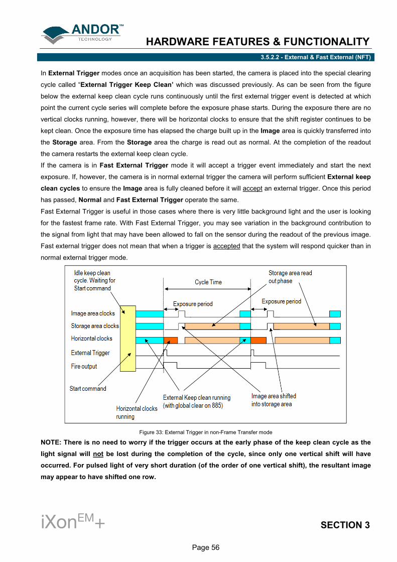
HARDWARE FEATURES & FUNCTIONALITY
iXonEM+ SECTION 3
Page 56
3.5.2.2 - External & Fast External (NFT)
In External Trigger modes once an acquisition has been started, the camera is placed into the special clearing
cycle called “External Trigger Keep Clean’ which was discussed previously. As can be seen from the figure
below the external keep clean cycle runs continuously until the first external trigger event is detected at which
point the current cycle series will complete before the exposure phase starts. During the exposure there are no
vertical clocks running, however, there will be horizontal clocks to ensure that the shift register continues to be
kept clean. Once the exposure time has elapsed the charge built up in the Image area is quickly transferred into
the Storage area. From the Storage area the charge is read out as normal. At the completion of the readout
the camera restarts the external keep clean cycle.
If the camera is in Fast External Trigger mode it will accept a trigger event immediately and start the next
exposure. If, however, the camera is in normal external trigger the camera will perform sufficient External keep
clean cycles to ensure the Image area is fully cleaned before it will accept an external trigger. Once this period
has passed, Normal and Fast External Trigger operate the same.
Fast External Trigger is useful in those cases where there is very little background light and the user is looking
for the fastest frame rate. With Fast External Trigger, you may see variation in the background contribution to
the signal from light that may have been allowed to fall on the sensor during the readout of the previous image.
Fast external trigger does not mean that when a trigger is accepted that the system will respond quicker than in
normal external trigger mode.
Figure 33: External Trigger in non-Frame Transfer mode
NOTE: There is no need to worry if the trigger occurs at the early phase of the keep clean cycle as the
light signal will not be lost during the completion of the cycle, since only one vertical shift will have
occurred. For pulsed light of very short duration (of the order of one vertical shift), the resultant image
may appear to have shifted one row.

HARDWARE FEATURES & FUNCTIONALITY
iXonEM+ SECTION 3
Page 57
For the 885 range of cameras, the Global Clear functionality is used to keep the image area free of charge prior
to the external trigger pulse. This reduces the pre-trigger image smear which might be seen on other frame
transfer sensors.
Also, in iCam-enhanced versions of the 885, this feature can be used to allow the overlap of exposure and
readout but still maintain a charge free sensor prior to the external trigger pulse, see figure 33 below:
Figure 34: ‘iCam-enhanced’ External Trigger in non-Frame Transfer mode (885)

HARDWARE FEATURES & FUNCTIONALITY
iXonEM+ SECTION 3
Page 58
3.5.2.3 - External Exposure (NFT)
External Exposure combined with Non-Frame Transfer readout is available to all iXonEM
+ cameras with
iCam technology. This mode is distinct from the triggering modes discussed previously in that the exposure
period is fully controlled by the width of the external trigger pulse. The exposure period starts on the positive
edge and concludes on the negative edge. The exposure is physically ended by shifting the Image area into the
Storage area. The Storage area is then readout in the normal manner.
On completion of the readout, the external keep clean cycle is started again.
Figure 35: External Exposure Trigger in Non-Frame Transfer mode

HARDWARE FEATURES & FUNCTIONALITY
iXonEM+ SECTION 3
Page 59
3.5.2.4 - Software trigger (NFT)
Software Trigger mode is only available in iCam-enabled iXonEM
+ cameras. This mode is particularly useful
when the user needs to control other equipment between each exposure and does not know in advance how
long such control will take or if the time taken changes randomly. With Software Trigger the camera and
software are in a high state of readiness and can react extremely quickly to a trigger event issued via software.
In this mode the camera will run the Idle Keep Clean Cycle until the Start command is issued by the PC which
is identical to all the modes previously discussed. On receipt of this command the camera will switch to running
the normal Internal Keep Clean until a Software Trigger command is issued by the PC. This event will start
the exposure and readout sequence. On completion of the readout the camera will return to the Internal Keep
Clean until the next Software trigger is issued.
Figure 36: Software trigger in non-frame transfer mode
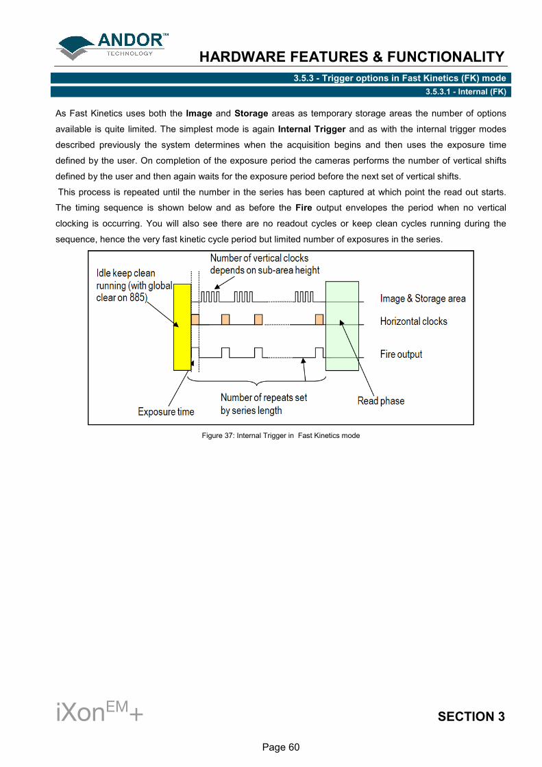
HARDWARE FEATURES & FUNCTIONALITY
iXonEM+ SECTION 3
Page 60
3.5.3 - Trigger options in Fast Kinetics (FK) mode 3.5.3.1 - Internal (FK)
As Fast Kinetics uses both the Image and Storage areas as temporary storage areas the number of options
available is quite limited. The simplest mode is again Internal Trigger and as with the internal trigger modes
described previously the system determines when the acquisition begins and then uses the exposure time
defined by the user. On completion of the exposure period the cameras performs the number of vertical shifts
defined by the user and then again waits for the exposure period before the next set of vertical shifts.
This process is repeated until the number in the series has been captured at which point the read out starts.
The timing sequence is shown below and as before the Fire output envelopes the period when no vertical
clocking is occurring. You will also see there are no readout cycles or keep clean cycles running during the
sequence, hence the very fast kinetic cycle period but limited number of exposures in the series.
Figure 37: Internal Trigger in Fast Kinetics mode

HARDWARE FEATURES & FUNCTIONALITY
iXonEM+ SECTION 3
Page 61
3.5.3.2 - External (FK)
In External Trigger mode, a trigger pulse is required to start each scan in the series. The rising edge of the
trigger defines the trigger event. The user can delay the start of the vertical shifting relative to the trigger event.
After the delay has elapsed, the number of rows (as specified by the user) are vertically shifted. The system
then waits for the next trigger to start the next scan. As there is no keep clean cycle running while waiting for
the external trigger the "real" exposure time is the time between each trigger. A consequence of this is that if
your experiment has a constant background signal, but your trigger period is not fixed, you may see different
background levels in your signal. As with internal trigger the data is only read off the sensor when the capture
sequence has completed.
Figure 38: External Trigger in Fast Kinetics mode

HARDWARE FEATURES & FUNCTIONALITY
iXonEM+ SECTION 3
Page 62
3.5.3.3 - External Start (FK)
External Start trigger mode is a combination of external and internal trigger. At the start of the capture
process the camera is running the external keep clean cycle waiting of a trigger pulse to be applied to the
External Trigger input. On receiving the trigger the exposure starts. The exposure period is defined by the user.
On completion of the exposure period, the camera performs the number of vertical shifts, defined by the sub-
area height (set by the user) and then, again, wait for the exposure period before the next set of vertical shifts.
This process is repeated until the number in the series has been captured at which point the readout starts.
Figure 39: External Start trigger in Fast Kinetics mode

HARDWARE FEATURES & FUNCTIONALITY
iXonEM+ SECTION 3
Page 63
3.7 - SHUTTERING
The iXon range of cameras can be supplied with a built in shutter. The shutter is intended for taking background
images and protecting the camera from excessive light and dust. It is not designed to operate at the high frame
rates the camera is capable off. Under normal operation the shutter should be set to Permanently Open and
the shutter open and close times to 0 seconds. If you do need the shutter to open and close automatically
during your experiment then set the opening and closing times to 50ms.

APPENDIX
iXonEM+ SECTION 4
Page 64
APPENDIX A1 - EMCCD TECHNOLOGY A1.1 - What is an Electron Multiplying CCD?
Current trends in photonics are placing unprecedented demands on detector technology to perform at
significantly greater levels of sensitivity and/or speed. Electron Multiplying Charge Coupled Device (EMCCD)
technology has been designed to respond to this growing need and in turn is opening up new avenues of novel
experimental design.
EMCCD technology, sometimes known as “on-chip multiplication”, is an innovation first introduced to the digital
scientific imaging community by Andor Technology in 2000, with the launch of our dedicated, high-end iXon
platform of ultra-sensitive cameras. Essentially, the EMCCD is an image sensor that is capable of detecting
single photon events without an image intensifier, achievable by way of a unique electron multiplying structure
built into the chip.
EM gain can be increased to a degree. It is readily adjustable in real time through the software, where
extremely weak signals may be detected above the read noise of the camera at any readout speed. This is
important because the traditional problem of combining sensitivity with speed in standard CCDs is that the two
are mutually exclusive, i.e. greater read noise detection limits result from faster pixel readout.
A1.2 - Does EMCCD technology eliminate Read Out Noise?
System noise within modern silicon based detectors has two primary sources: dark current noise and read
noise. The higher the noise floor on a detector the less able it is to read out the extremely weak signals
associated with ultra low light imaging.
With thermoelectric cooling, dark current noise can be reduced to negligible levels. An EMCCDs ability to
multiply weak signals above the detector’s read noise floor, by applying EM gain, effectively eliminates read
noise at any speed by reducing it to << 1 e-/p/s.
A1.3 - How sensitive are EMCCDs?
Two parameters significantly influence detector sensitivity, namely Quantum Efficiency (QE) and system noise.
QE is a measure of a camera’s ability to capture valuable photons. A high QE results in more photons being
converted to photoelectrons within the CCD pixels.
Once converted, the photoelectrons in a given pixel must overcome the detection limit or noise floor of the
camera, which is set by the system noise. EMCCDs deliver superior sensitivity by maximizing QE and
minimizing system noise, through the unique gain control feature. Single photon events are now well within the
capabilities of super sensitive EMCCD technology.

APPENDIX
iXonEM+ SECTION 4
Page 65
A1.4 - What applications are EMCCDs suitable for?
EMCCD based detectors have been designed for the most demanding of low light, dynamic applications. These
detectors have redefined the sensitivity expectations of scientific grade cameras, with a detection limit as low as
single photons.
These levels of sensitivity are vital for low light, life science and physical science imaging applications such as
single molecule detection, live cell microscopy, weak luminescence detection, or demanding astronomy
applications (to name only a few).
A1.5 - What is Andor Technology's experience with EMCCDs?
Andor Technology was the first company to introduce an EMCCD based detector in 2000. Since then the
company has led the way in the development of EMCCD detectors, introducing the first back illuminated
EMCCD in January 2003.
Andor now offers the widest range of EMCCD based detectors on the market. The company is also playing a
pivotal role in increasing our understanding of this ground-breaking technology.
In September 2003 it hosted the 1st International EMCCD Symposium in Limavady, Northern Ireland, a
dedicated conference which looked at the current usage and future development of EMCCDs. This was
followed in April 2005 by the 2nd
International EMCCD Symposium, held in Connecticut, USA. Please go to
www.emccd.com for further details.

APPENDIX
iXonEM+ SECTION 4
Page 66
A2 - EMCCD SENSOR
The EMCCD sensor is the core enabling technology of the system. Everything else in the camera has been
designed to extract the absolute best operational performance from this sensor. All EMCCD sensors in the
iXonEM
+ range have frame transfer architecture. The frame-transfer EMCCD uses a two-part sensor in which
one-half of the array is used as a storage region and is protected from light by a light-tight mask. Incoming
photons are allowed to fall on the uncovered portion of the array and the accumulated charge is then rapidly
shifted into the masked storage region for transfer to the serial output register. While the signal is being
integrated on the light-sensitive portion of the sensor, the stored charge is read out. Frame transfer devices
have typically faster frame rates than full frame devices and have the advantage of a high duty cycle i.e. the
sensor is always collecting light.
A potential disadvantage of this architecture is the charge smearing during the transfer from the light-sensitive
to the masked regions of the CCD, (although they are significantly better than full frame devices).The smearing
being more prevalent when exposure times are closer to the time taken to shift the charge under the mask (in
the order of milliseconds).
The Andor iXonEM
+ is the best camera on the market for minimizing such smear, as the vertical clock speeds
can be tuned via the software to deliver the fastest parallel shifts in the industry, which has the further
advantage of faster overall frame rates (especially when using sub-array and/or pixel binning readout options).
Essentially, the EMCCD sensor is capable of detecting single photon events without an image intensifier,
achievable by way of a unique electron multiplying structure built into the chip. Traditional CCD cameras offered
high sensitivity, with readout noises in single figure <10e- but at the expense of slow readout. Hence they were
often referred to as ‘slow scan’ cameras. The fundamental constraint came from the CCD charge amplifier. To
have high speed operation the bandwidth of the charge amplifier needs to be as wide as possible but it is a
fundamental principle that the noise scales with the bandwidth of the amplifier hence higher speed amplifiers
have higher noise.
Slow scan CCD’s have relatively low bandwidth and hence can only be read out at modest speeds typically less
than 1MHz. EMCCD cameras avoid this constraint by amplifying the charge signal before the charge amplifier
and hence maintain unprecedented sensitivity at high speeds. By amplifying the signal the readout noise is
effectively by-passed and as such, EMCCD readout noise is no longer a limit on sensitivity (and can often be
considered negligible).
See pages 22 & 23 for further details on EMCCD technology and sensor architecture.

APPENDIX
iXonEM+ SECTION 4
Page 67
A3 - VACUUM HOUSING
Unless protected, cooled CCD sensors will condense moisture, hydrocarbons and other gas contaminants that
will attack the CCD surface. If that happens, CCD performance will decline proportionally and will eventually fail.
Fortunately, the integrity of the sensor can be preserved by housing it in a protective enclosure. However, it is
important to understand that all such environments are not the same and the underlying technology used can
seriously impact camera life (and performance).
A permanent hermetic vacuum head is an essential component of high-end imaging and spectroscopy EMCCD
cameras. A permanent vacuum requires not only a hermetic seal, but also low outgassing. These criteria are
what Andor’s UltraVacTM
vacuum process uniquely ensures. It is the low outgassing (see page 70) that is the
real challenge and, in reality, what sets the real limit on long-term performance. Andor has developed and
utilized the UltraVacTM
process over more than 10 years, so it is proven with 1000’s of systems in the field and a
measured Mean-Time-Between-Failure (MTBF) of 100 years; that means it will take 100 years for half of them
to fail!
Furthermore, Andor’s rigorous, proprietary vacuum process is carried out in a Class 10,000 clean room;
this means less than 10,000 particles of less than 0.5 micron dimension per cubic meter. The air is fully
replenished every minute. We welcome visitors to inspect our state-of-the-art facility.
Sustained vacuum performance over many years operation – proprietary process to minimize
outgassing.
Benefit from a thoroughly proven solution - UltraVacTM
. 10 years of shipping vacuum systems to the
field and a negligible failure rate (an MTBF of 100 years).
Performance improves because the temperature of the chip can be reduced significantly. Better cooling
(down to -100°C with an enhanced thermoelectric Peltier design) translates into substantially lower
darkcurrent and fewer blemishes.
Such darkcurrent performance is particularly critical to EMCCD technology, where even a single
thermal electron is detected as a spurious noise spike.
Elimination of condensation and outgassing means that the system can also use only a single entrance
window, with antireflection coating – you can believe the QE curve.
The permanent hermetic vacuum ensures that peak quantum efficiency and cooling will not degrade,
even after years of operation.

APPENDIX
iXonEM+ SECTION 4
Page 68
A3.1 - Thermoelectric cooler
The iXonEM
+ range makes use of a four-stage (see NOTE below), Peltier cooling assembly, which utilizes the
thermoelectric effect to rapidly cool the sensor down to the stable operating temperature. TE coolers have a
cold end (in contact with the sensor) and a hot end. Heat must be efficiently dissipated from the TE cooler for
effective cooling of the sensor.
The iXonEM
+ is expertly designed to yield maximum heat dissipation, via either forced air cooling (in-built fan) or
water cooling, which in combination with Andor’s UltraVacTM
vacuum process, results in market-leading cooling
performance. A recirculator or a chiller can be purchased from Andor Technology to provide convenient and
effective heat dissipation through water cooling.
The iXonEM
+ camera also contains temperature control components, which regulate the cooling of the camera
and ensure that a stable temperature is maintained between and throughout measurements.
Figure 40: UltravacTM
metal hermetic vacuum sealing
NOTE: DV885 models have a three-stage peltier; DU885 models have a four-stage peltier.

APPENDIX
iXonEM+ SECTION 4
Page 69
A4 - OUTGASSING
Outgassing is the release of a gas trapped in material. It is a problem encountered in high-vacuum applications.
Materials not normally considered absorbent can release enough molecules to contaminate the vacuum and
cause damage to optical sensors, window coatings, etc.
Even metals and glasses can release gases from cracks or impurities, but sealants, lubricants, and adhesives
are the most common cause. Left unchecked, cooling performance would steadily degrade and therefore lead
to increased dark current. Furthermore, resulting electrochemical reactions would eventually destroy the sensor.

APPENDIX
iXonEM+ SECTION 4
Page 70
A5 - CONTROLLER CARD PINOUTS
WARNING: Pins 11, 12 & 13 are reserved. These pins are NOT available for auxiliary use. DO NOT make
electrical connections to these pin locations when attaching external devices via the Controller Card
Auxiliary Connector Port. Doing so may cause damage to the Controller Card, the Camera or your
external device.

APPENDIX
iXonEM+ SECTION 4
Page 71
A6 - SMB SIGNAL DIAGRAMS
Figure 41: External Trigger SMB
Figure 42: Fire SMB & Shutter SMB

APPENDIX
iXonEM+ SECTION 4
Page 72
A7- MECHANICAL DIMENSIONS (860, 885 & 897 models)

APPENDIX
iXonEM+ SECTION 4
Page 73
A8- MECHANICAL DIMENSIONS (888 models)

APPENDIX
iXonEM+ SECTION 4
Page 74
A9 - TERMS & CONDITIONS
1. In these Conditions:
‘BUYER’ means the person who accepts a quotation of the Seller for the sale of the Goods or whose order for
the Goods is accepted by the Seller.
‘GOODS’ means the goods (including any instalment of the goods or any parts for them) which the Seller is
to supply in accordance with these Conditions.
‘SELLER’ means Andor Technology plc.
‘CONDITIONS’ means the standard terms and conditions of sale set out in this document and (unless the
context otherwise requires) includes any special terms and conditions agreed in writing between the Buyer
and Seller.
‘CONTRACT’ means the contract for the purchase and sale of the Goods.
‘WRITING’ includes telex, cable, facsimile transmission and comparable means of communication.
2. Any reference in these Conditions to any provision of a statute shall be construed as a reference to that
provision as amended, re-enacted or extended at the relevant time.
3. The headings in these Conditions are for convenience only and shall not affect their interpretation.

APPENDIX
iXonEM+ SECTION 4
Page 75
A10 - WARRANTIES & LIABILITY
1. Subject to these Conditions set out below, the Seller warrants that the Goods will correspond with their
specification at the time of delivery and will be free from defects in material and workmanship for a period of 12
months from the date of delivery.
2. The above warranty is given by the Seller subject to the following conditions:
2.1 the Seller shall be under no liability in respect of any defect in the Goods arising from any drawing, design
or specifications supplied by the Buyer;
2.2 the Seller shall be under no liability in respect of any defect arising from fair wear and tear, wilful damage,
negligence, abnormal working conditions, failure to follow the Seller’s instructions (whether oral or in writing),
misuse or alteration, or repair of the Goods without the Seller’s approval;
2.3 the Seller shall be under no liability under the above warranty (or other warranty, condition or guarantee) if
the total price for the Goods has not been paid by the due date for payment;
2.4 the above warranty does not extend to parts, material or equipment not manufactured by the Seller, in
respect of which the Buyer shall only be entitled to the benefit of any such warranty or guarantee as is given by
the manufacturer to the Seller.
3. Subject as expressly provided in these conditions, and except where the Goods are sold to a person dealing
as a consumer (within the meaning of the Unfair Contract Terms Act 1977), all warranties, conditions or other
terms implied by statute or common law are excluded to the fullest extent permitted by law.
4. Any claim by the Buyer which is based on any defect in the quality or condition of the Goods or their failure to
correspond with specification shall (whether or not delivery is refused by the Buyer) be notified in Writing to the
Seller within 7 days from the date of delivery or (where the defect or failure was not apparent on reasonable
inspection) discovery of the defect or failure. If delivery is not refused, and the Buyer does not notify the Seller
accordingly, the Buyer shall not be entitled to reject the Goods and the Seller shall have no liability for such
defect or failure, and the Buyer shall be bound to pay the price as if the Goods had been delivered in
accordance with the Contract. In no event shall the Buyer be entitled to reject the Goods on the basis of any
defect or failure which is so slight that it would be unreasonable for him to reject them.

APPENDIX
iXonEM+ SECTION 4
Page 76
5. Where any valid claim in respect of the Goods which is based on any defect in the quality or condition of the
Goods or their failure to meet specification is notified to the Seller in accordance with these Conditions, the
Seller shall be entitled to replace the Goods (or the part in question) free of charge or, at the Seller’s sole
discretion, refund to the Buyer the price of the Goods (or a proportionate part of the price), but the Seller shall
have no further liability to the Buyer.
6. Except in respect of death or personal injury caused by the Seller’s negligence, the Seller shall not be liable
to the Buyer by reason of any representation (unless fraudulent), or any implied warranty, condition or other
term, or any duty at common law, or under the express terms of the Contract, for any indirect, special or
consequential loss or damage (whether for loss of profit or otherwise), costs, expenses or other claims for
compensation whatsoever (whether caused by the negligence of the Seller, its employees or against otherwise)
which arise out of or in connection with the supply of the Goods, or their use or resale by the Buyer and the
entire liability of the Seller under or in connection with the Contract shall not exceed the price of the goods,
except as expressly provided in these Conditions.
7. The Seller shall not be liable to the Buyer or be deemed to be in breach of the Contract by reason of any
delay in performing, or any failure to perform, any of the Seller’s obligations in relation to the goods, if the delay
or failure was due to any cause beyond the Seller’s reasonable control. Without prejudice to the generality of
the foregoing, the following shall be regarded as causes beyond the Seller’s reasonable control:
7.1 Act of God, explosion, flood, tempest, fire or accident;
7.2 war or threat of war, sabotage, insurrection, civil disturbance or requisition;
7.3 acts, restrictions, regulations, bye-laws, prohibitions or measures of any kind on the part of any
governmental, parliamentary or local authority;
7.4 import or export regulations or embargoes;
7.5 strikes, lock-outs or other industrial actions or trade disputes (whether involving employees of the Seller or
of third party);
7.6 difficulties in obtaining raw materials, labour, fuel, parts or machinery;
7.7 power failure or breakdown in machinery.