Embed Size (px)
Citation preview

ISSUES IN CONFORMANCE TESTING: M U L TI PLE SEM ICONTROLLABLE
INTERFACES
Mariusz A. Fecko
Computer and Information Science Department
University of Delaware, Newark, DE
M. Umit Uyar*
Department of Electrical Engineering
City College of the City University of New York
Adarshpal S. Sethi, Paul D. Amer
Computer and Information Science Department
University of Delaware, Newark, DE
Abstract In a testing environment, where an IUT communicates with multiple entities, a tester may have differing degrees of controllability on the interactions between these entities and the IUT: directly controllable, semicontrollable, or uncontrollable. In this paper, a graph conversion algorithm is introduced that offers the testability of both the directly and semicontrollable inputs, while avoiding race conditions. Although, for the most general case, the graph conversion results in an exponentially large number of nodes, practical considerations make the converted graph size feasible. Currently, this methodology is being applied to generate tests for MIL-STD 188-220B, which increases the number of testable state transitions from approximately 200 to over 700.
"Dr. Uyar performed this research while a Visiting Associate Professor at University of Delaware.
The original version of this chapter was revised: The copyright line was incorrect. This has beencorrected. The Erratum to this chapter is available at DOI:
© IFIP International Federation for Information Processing 1998S. Budkowski et al. (eds.), Formal Description Techniques and Protocol Speci�cation, Testing and Veri�cation
10.1007/978-0-387-35394-4_29The original version of this chapter was revised: The copyright line was incorrect. This has beencorrected. The Erratum to this chapter is available at DOI:
© IFIP International Federation for Information Processing 1998S. Budkowski et al. (eds.), Formal Description Techniques and Protocol Speci�cation, Testing and Veri�cation
10.1007/978-0-387-35394-4_29

112
1 INTRODUCTION
Due to increasing complexity of communication protocols, automated generation of conformance tests based on the formal descriptions has been an active research area [Ural, 1992] - [Sarikaya et al., 1987]. One problem that exists in today's conformance testing stems from the limited controllability of an Implementation Under Test (IUT), which almost always renders certain protocol features untestable. Ideally, testers should be able to generate every possible input that is defined in the Finite State Machine (FSM) modeling an IUT. Similarly, all outputs generated by an IUT should be observable by the testers.
Unfortunately, in practice, these two situations often are not possible. Testers may not have a direct access to all interface(s) in which the IUT accepts inputs. Typically, for an (N)-layer IUT, an exposed interface exists only between the IUT and the (N-l)-Service Provider [IS9646, 1991]. Interfaces with the upper layer, or with the peer entities (such as timers, etc.) are not directly accessible. In such cases, the interactions that involve these not directly controllable interfaces introduce non-determinism and/or race conditions during testing, leaving certain portions of the IUT model untestable.
Consider an (N)-layer IUT communicating with an entity FSMi that does not have interfaces directly accessible by the tester (i.e., the tester cannot apply inputs to FSMi ). In some cases, FSMi can be utilized to generate otherwise not directly controllable inputs to the IUT. An output from the IUT to the FSMi can force the FSMi to generate a response as the desired input from F S Mi to the IUT. If the tester can apply an appropriate input to the IUT, the IUT, in turn, triggers such an interaction between the IUT and FSMi. In this case, some of the interfaces become semicontrollable (as opposed to uncontrollable) .
Another difficulty that arises when there are multiple interfaces interacting with the IUT is the possible occurrence of race conditions. If an IUT moves into a state at which several inputs from different interfaces are waiting, choosing which input is consumed first may cause non-determinism.
There are many real-life protocols that possess either semicontrollable inputs, or race conditions, or both, due to a tester's limited control over the interactions between the IUT and other communicating entities. For example, in MIL-STD 188-220B [188-220B, 1998], over 70% of the transitions cannot be directly controlled. The race conditions can be shown in the IEEE 802.2 LLC Connection Component protocol [lS08802-2, 1994].
Some problems due to the limited controllability over the IUT are addressed in the literature. Testing embedded systems [Rayner, 1987, Timohovich, 1993] where uncontrollable events may take place is discussed in [Phalippou, 1992] and [Cavalli et al., 1996]. The ferry clip testing method by [Zeng et al., 1989], and the Astride testing method by [Rafiq and Castanet, 1990] are introduced to enhance the controllability of inputs to an IUT. Deriving test sequences by combining the IUT and a single entity communicating with it into a global FSM are proposed in [Timohovich, 1993]. The testing system considered in this paper does not assume any user-defined entities within the SUT (as implied by [Zeng et al., 1989] and [Rafiq and Castanet, 1990]). Also, a global FSM is not built to avoid state explosion problem.

113
(a) SUT (b) SUT
FSM 1 FSM2 ... I FSM 1 I • PCDs (N+ 1 )-Iayer •
11 12 bt tc __ ----------- - - - - - -- ---------- ------------- - -
I I Lower N-PDUs IUT FSM F•1 IUT Tester
- - - ...
(l) (l) JyFSMF I
(N)-Iayer
- -- -------------- --------------------------------1 td- - - --10 a
I (N-1 )-Service Provider
I
Figure 1 (a) Testing IUT with multiple interfaces; (b) Testing (N)-Iayer IUT with an (N+l)-Iayer semicontrollable interface.
This paper introduces a methodology that utilizes an IUT's semicontrollable interfaces while avoiding the race conditions. An algorithm is presented to modify an IUT's directed graph representation such that the semicontrollable portions of the IUT become directly controllable, where possible. In the most general case, such a graph conversion results in an exponentially large number of nodes. However, special considerations such as a small number of interfaces interacting with an IUT, and diagnostics considerations can make the problem size feasible for most practical cases.
The algorithm presented in this paper is being applied to MIL-STD 188-220B protocol to generate conformance tests. Initial results are promising: the number of testable transitions increased to over 700 from approximately 200 for the Class A - Type 1 Service Datalink module [Fecko et al., 1997].
This paper is organized as follows. Section 2 formally defines the controllability problem, which is practically motivated in Section 3 by examples from real-life protocols. Section 4 defines a system model for a testing environment with multiple interfaces with different degrees of controllability. Practical issues are introduced into this model in Section 5. An algorithm to modify an IUT's graph so that semicontrollable interfaces can be fully utilized while avoiding the race conditions is presented in Section 6. In Section 7, the application of minimum-cost test sequence generation techniques is discussed.
2 CONTROLLABILITY PROBLEM
Consider a testing environment shown in Figure 1 (a). The System Under Test (SUT) contains an IUT, which interacts with F FSMs. FSM1,"', FSMF, implemented inside the SUT, interact with the IUT through interfaces II, ... ,IF' The points at which a testing system can apply inputs to and observe outputs from the IUT are called points of control and observation

114
(PCDs) [1S9646, 1991J. Each JUT's interface is associated with a full-dpplex PCD through which inputs and outputs can be exchanged. The inputs can be of three different types:
• directly controllable: a tester can directly apply the inputs to the JUT through the PCD
• semicontrollable: a tester cannot directly apply the inputs to the JUT through the PCD. However, it is possible to utilize one of the FSMs interacting with the JUT to supply these inputs indirectly
• uncontrollable: the inputs may be supplied through a PCD without any explicit action of the tester. This means that inputs may be generated during testing without the tester's control
The inputs at a given PCD can belong to one or more of these three types. If a PCD has any semicontrollable inputs and does not have any uncontrollable inputs, we say that its associated interface is semicontrollable. If there are no semicontrollable or uncontrollable inputs, the interface is called directly controllable. In this paper, without loss of generality, we consider that each interface has only one type of input: either directly controllable or semicontrollable. The analysis also is applicable to interfaces with a combination of directly controllable and semicontrollable inputs (excluding uncontrollable ones).
A typical example of a directly controllable interface is a Lower Tester FSM [IS9646, 1991J. A timer FSM, whose only inputs come from an JUT (e.g., start, restart, and stop the timer), is a typical semicontrollable interface.
In the testing framework of Figure 1 (a), the tester is unable to supply inputs directly to the JUT through interfaces II,"', IF. Therefore, the interfaces h,"',IF are only semicontrollable, provided that FSM1 ,"',FSMF can be utilized to supply inputs to the IUT. Dn the other hand, the tester can apply inputs to the JUT directly by using a Lower Tester (LT) , which exchanges N-PDUs with the JUT by using the (N-l)-Service Provider. The interface 10 between the LT and the JUT is therefore directly controllable (10 can be considered an interface between the LT and the JUT, because the (N-l)-Service Provider acts as a pass-through that does not alter inputs or outputs).
To test the JUT's transitions triggered by the inputs from h the tester must use one of the directly controllable interfaces to force the IUT to generate outputs to h These outputs are applied to FSMi at Ns PCD. As response to these outputs, FSMi will send back inputs to the JUT through h These inputs will trigger the appropriate transitions in the JUT.
Consider the SUT shown in Figure 1 (b). The LT, which exchanges N-PDUs with an (N)-layer JUT, represents a directly controllable interface 10 , Since the interface h is not exposed in the SUT, a tester can neither directly apply inputs to the JUT nor observe the JUT's outputs to the (N+l)-layer. In this case, II is at best only semicontrollable. To apply (N+l)-layer's inputs to the JUT through II, the LT must generate inputs to the JUT through its directly controllable interface 10 . In response, the IUT will generate outputs to FSMI through h. Subsequently, in response to these outputs, FSM1 will generate inputs to the JUT at II.
This paper addresses the problem of generating optimal realizable test sequences in an environment with multiple semicontrollable interfaces. This problem will be referred to as the controllability problem.
Transition Inpul (Evenl)
TO Data_Request T1 LCMO (P.o) and P _Flag.o T2 I_CMO (P.l) with Unexpected N(s) T3 Data_Request T4 I_CMO TS I_RSP (F.l) with Unexpected N(s)
Lower Tester
Out"", (Action)
I_CMO Data_Indication Raj_RSP (F.l) I_CMO Data_Indication Raj_XXX (X=O)
controllable interface
SUT ------------------------------:,--------------------,
Upper layer FSM
semicontrollabki interface
Data Request 1 1 Data Indication
LLC layer IUT
T3
, :_L_-_-__ -_-_-__ -_-_-_-__ -_-_-__ -_-_-_-__ -_-_-__ __ :
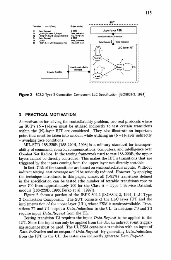
Figure 2 802.2 Type 2 Connection Component LLC Specification [1508802-2, 1994]
3 PRACTICAL MOTIVATION
115
As motivation for solving the controllability problem, two real protocols where an SUT's (N + 1 )-layer must be utilized indirectly to test certain transitions within the (N)-layer ruT are considered. They also illustrate an important point that must be taken into account while utilizing an (N + 1 )-layer indirectly - avoiding race conditions.
MIL-STD 188-220B [188-220B, 1998] is a military standard for interoperability of command, control, communications, computers, and intelligence over Combat Net Radios. In the testing framework used to test 188-220B, the upper layers cannot be directly controlled. This makes the IUT's transitions that are triggered by the inputs coming from the upper layer not directly testable.
In fact, 70% of the transitions are based on semicontrollable inputs. Without indirect testing, test coverage would be seriously reduced. However, by applying the technique introduced in this paper, almost all (>95%) transitions defined in the specification can be tested (the number of testable transitions rose to over 700 from approximately 200 for the Class A - Type 1 Service Datalink module [188-220B, 1998, Fecko et al., 1997]).
Figure 2 shows a portion of the IEEE 802.2 [IS08802-2, 1994] LLC Type 2 Connection Component. The SUT consists of the LLC layer ruT and the implementation of the upper layer (UL), whose FSM is semicontrollable. 'Iransitions Tl and T4 output a Data_1ndication to the UL. 'Iransitions TO and T3 require input Data_Request from the UL.
Testing transition T3 requires the input Data_Request to be applied to the ruT. Since this input can only be applied from the UL, an indirect event triggering sequence must be used. The UL FSM contains a transition with an input of DataJndication and an output of Data_Request. By generating DataJndication from the IUT to the UL, the tester can indirectly generate Data_Request.

116
No transition in Reject outputs a DataJndication to the UL. Therefore, a Data_Indication must be sent to the UL while the IUT is in another state. Then the IUT must be moved into the Reject before the UL outputs its Data_Request. For example, one straightforward solution is to use transition Tl. The tester applies to the IUT an input LCMD with the appropriate parameters and flags. The IUT outputs a DataJndication to the UL. Then the tester brings the IUT to Reject state by applying an LCMD through transition T2. Now transition T3 will be triggered by Data_Request that by then has arrived from the UL.
Unfortunately, this solution has a race condition: in the Normal state, after the Data_Indication is output as a result of traversing Tl, if a Data_Request arrives from the UL before the tester applies T2's input LCMD, then the Data_Request will be consumed by transition TO before transition T2 fires. To avoid this race condition after an indirectly generated DataJndication, the tester must find a way of moving the IUT to the Reject state through states in which a Data_Request cannot be consumed. Consider Await state with transition T4 that can be used to generate a DataJndication. There is no race condition here, because the Await state cannot process a Data_Request. A tester has sufficient time to move the IUT to Reject state through transition T5, where a Data_Request buffered in the interface will trigger T3.
As can be seen from this example, the IUT can move into a state where the IUT is forced to consume a previously buffered input. This creates a race condition if the test sequence requires that a different input be sent to the IUT by the LT. Therefore, a test sequence without such race conditions will not bring the IUT into a state where multiple inputs are pending (one from the LT, and others from the buffers). Instead, the test sequence should traverse the IUT transitions in an order that avoids these race conditions.
4 MODELING TEST SYSTEMS WITH CONTROLLABILITY ISSUES
Among the widely used specification formalisms to model protocol implementations are labelled transition systems (LTS) and Finite State Machines (FSM) [Tretmans, 1996]. In an LTS, the inputs and outputs for a system are not distinguished, but instead represented as interactions. The LTS allows an interaction to occur if both an implementation and an environment are able to perform that interaction.
An FSM, on the other hand, is a subset of an LTS where, for every state transition, an input is coupled with one or more outputs (including a null output). In this paper, an FSM model, which is sufficient to model protocols with finite state space and deterministic behavior, is used to represent an implementation.
Let us consider an IUT interacting with multiple semicontrollable interfaces. The goal of test generation in this environment is to derive a set of tests exercising each transition in an JUT's FSM at least once. Specifically, given a graph G representing an IUT's FSM, we want to find a minimum-cost tour of G such that each transition is covered at least once.
Given the graph G(V, E) representing an FSM model of an IUT with multiple semicontrollable interfaces, let us define the following parameters:
• IVI - number of nodes in G • F-number of semicontrollable interfaces interacting with the IUT

Lower Tester
(LT)
Figure 3 IUT interacting with two semicontrollable interfaces.
117
• Ti C E - subset of edges in G triggered by the inputs from the i-th semicontrollable interface
• bi - buffer size (maximum number of inputs buffered) at the i-th semi-controllable interface Ii
• Ai - set of inputs triggering transitions in Ti
• Oi - set of outputs of the JUT that force inputs in Ai to be buffered at Ii
• Ci - number of different transition classes in the JUT triggered by inputs at Ii. Two transitions t1 and t2 belong to the same transition class Ti,j C Ti
iff they both become fireable by the same input ai,j E Ai
• Ui,j C E - set of transitions in the JUT with output Oi,j such that, in response to Oi,j, an input ai,j E Ai is buffered at Ii
Let Ai = {ai,l, ... , ai,c;} and Oi = {Oi,l, ... , Oi,mi }. Then the sets of Ti,j, Ui,j,
Ti, and Ui, are defined formally as follows:
de! ) Ui,j = {e E E : output(e = Oi,j}
Ci Ci
de! U Ti = Ti,j de! U Ui = Ui,j j=l j=l
There may be several outputs in set Oi that force input ai,j to be buffered at Ii. For simplicity, let Oi,j denote any output forcing ai,j at Ii. Based on the above definitions, transitions triggered by the inputs from the semicontrollable interface Ii are divided into Ci classes, each corresponding to a distinct input that fires any transition within the class. No transition can belong to more than one Ti,j. Similarly, each transition can belong to only one Ui,j. In general, Ti,j
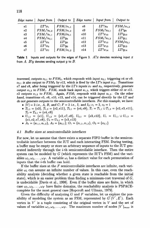
and Ui,j mayor may not be disjoint. Example: Consider the IUT of Figure 3 which is interacting with FSM1 and
FSM2 through the semicontrollable interfaces h and 12 , respectively. The IUT's FSM is described in Table 1. 'Iransition el, triggered by input Xl from the LT, generates output 01,1 to FSM1. In response, FSM1 sends back input a1,1 which triggers transition e3. (In general, ai,j is the expected response to Oi,j.) e3, when
118
Edge name I Input from I Output to " Edge name I Input from I Output to
el LT?X1 FSMdo1,l e8 LT?xs FSM1!01,2 e2 FSM1?a1,2 FSMdo1,2 e9 FSM2?a2,l LT!Y9 e3 FSM1?a1,l FSM2!02,l elO LT?XlO LT!ylO e4 FSM2?a2,l LT!Y4 ell FSM1 ?a1,2 LT!Yll e5 LT?X5 LT!Y5 el2 LT?X12 FSM2!02,l e6 LT?X6 LT!Y6 el3 LT?X13 LT!Y13 e7 LT?X7 FSM1!01,2 el4 LT?X14 LT!Y14
Table 1 Inputs and outputs for the edges of Figure 3. A?x denotes receiving input x from A. Bly denotes sending output y to B.
traversed, outputs 02,1 to FSM2, which responds with input a2,l triggering e4 or e9. 02,1 is also output to FSM2 bye12, which is fired by the LT's input X12. Transitions e7 and e8, after being triggered by the LT's inputs X7 and Xs, respectively, generate output 01,2 to FSM1. FSM1 sends back input a1,2, which triggers either e2 or ell. e2 outputs 01,2 to FSM1. Again, FSM1 responds with input a1,2. On the other hand, transitions e5, e6, elO, e13, and e14, can be triggered directly by the LT and do not generate outputs to the semicontrollable interfaces. For this example, we have:
• IVI = 3 i.e., A, B, and C; F = 2 i.e., hand 12; C1 = 2, C2 = I • T1,l = {e3}, T1,2 = {e2, ell}, T2,l = {e4, e9}, T1 = T1,l U T1,2 = {e2, e3, ell},
T2 = T2,l = {e4, e9} • U1,l = {ell, U1,2 = {e2,e7,e8}, U2,l = {e3,eI2}, U1 = U1,l U U1,2 =
{el,e2,e7,e8}, U2 = U2 ,l = {e3,e12} • A1 = {a1,l,a1,2}, A2 = {a2,d; 01 = {01,l,01,2}, O2 = {02,d
4.1 Buffer sizes at semi controllable interfaces
For now, let us assume that there exists a separate FIFO buffer in the semicontrollable interface between the IUT and each interacting FSM. During testing, a buffer may be empty or store an arbitrary sequence of inputs to the IUT generated indirectly through the i-th semicontrollable interface. Then the entire system can be modeled by G (which represents the IUT's FSM) and the variables Wl, W2, ... , W F. A variable Wi has a distinct value for each permutation of inputs that the i-th buffer can hold.
If the buffer sizes at the F semicontrollable interfaces are infinite, each variable Wi can assume an infinite number of values. In this case, even the reachability analysis (deciding whether a given state is reachable from the initial state), which is an easier problem than finding a minimum-cost traversal of G, is undecidable [Davis et al., 1998]. Even if the buffer sizes are finite, in which case Wl, W2, ... , W F have finite domains, the reachability analysis is PSPACEcomplete for the most general case [Hopcroft and Ullman, 1979).
Given the difficulty of analyzing G and F variables, let us explore the possibility of modeling the system as an FSM, represented by a' (V' , E'). Each vertex in V'is a tuple consisting of the original vertex in V and the set of values of variables Wl, W2,"" WF. The maximum number of nodes W'lma", is
119
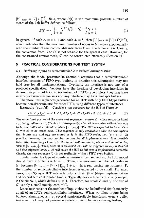
IV'lma:!: = IVI * II::1 B(i), where B(i) is the maximum possible number of states of the i-th buffer defined as follows:
B(i) = { (1- c;+bi)/(l - Ci) Ci > 1 1 + bi If Ci = 1
(1)
In general, if each Ci = C > 1 and each bi = b, then 1V'lma:!: = IVI * O(cbF ),
which indicates that the maximum number of nodes in a' grows exponentially with the number of semicontrollable interfaces F and the buffer size b. Clearly, the conversion from G to a' is not feasible for the general case. However, for the constrained environment, a' can be constructed efficiently (Section 7).
5 PRACTICAL CONSIDERATIONS FOR TEST SYSTEM
5.1 Buffering inputs at semicontrollable interfaces during testing
Although the model presented in Section 4 assumes that a semicontrollable interface consists of FIFO-type buffers, in practice this assumption may not hold true for all implementations. Typically, the interface is not part of a protocol specification. Vendors have the freedom of developing interfaces in different ways: in addition to (or instead of) FIFO-type buffers, they may have interrupt-driven mechanisms and any interface may have multiple buffers.
Therefore, test sequences generated for an ruT with only FIFO-type buffers become non-deterministic for other ruTs using different types of interfaces.
Example (cont'd): Consider a test sequence for the IUT of Figure 3:
e14,el,e8,e3,e4,ell,e13,e12,e5,e9,e7,e2,e13,ell,e13,e6,elO,e6 (2)
The underlined portion ofthe above test sequence traverses el, which results in input al,l being buffered at It (Table 1). Subsequently, when e8 is executed with output 01,2
to 11, the buffer at It should contain [al,l,al,2]. The IUT is expected to be in state C with e3 to be tested next. This sequence is only realizable under the assumption that inputs al,l and al,2 are stored at It in the FIFO order, i.e., [al,l, al,2]. In practice, however, this may not be the case for all implementations. It is possible that, after traversing el and e8, the buffer will contain inputs in a different order, such as [al,2, al,d. Then, after e8 is traversed, ell will be triggered by al,2 instead of e3 being triggered byal,l. e3 will cause the IUT to fail even if implemented correctly. Clearly, the test sequence (2) is not realizable without FIFO-type buffers.
To eliminate this type of non-determinism in test sequences, the IUT model should have a buffer size bi = 1. Then, the maximum number of nodes in a' becomes 1V/lma:!: = IVI * IIr=l (1 + Ci). In a real testing environment, F, the number of semicontrollable interfaces, is expected to be small. For most cases, the (N)-layer ruT interacts only with an (N+l)-layer implementation and several semicontrollable timers. Typically, for each timer, the only output is the timeout, which defines Ci as 1. Therefore, for small F and Ci, the size of a' is only a small multiplicant of G.
Let us now consider the number of inputs that can be buffered simultaneously at all of an IUT's semicontrollable interfaces. When we allow inputs being buffered simultaneously at several semicontrollable interfaces, even a buffer size equal to 1 may not prevent non-deterministic behavior during testing.

120
Example (cont'd): Consider a potential test sequence for Figure 3 generated for buffer sizes of 1 at h and h:
e14,e13,e12,e7,e9,ell,el,elO,e3,e4,e12,e5,e9,e7,e2,el3,ell,e13,e6
Although this sequence avoids the non-determinism due to buffer sizes shown previously in (2), it may still be non-deterministic due to the IUT interacting with multiple interfaces simultaneously. Consider the underlined portion of the above sequence. After e12 is traversed, input a2,1 is buffered at 12. TI-aversing e7 results in al,2 being buffered at 11. Since a2,1 was generated earlier than al,2, transition e9 is expected to be triggered instead of e2. In reality, due to the unknown response time of the interfaces, a2,1 can be applied to the IUT earlier than, later than, or simultaneously with al,2. In this case, the behavior of the IUT will be non-deterministic, thereby making the test sequence invalid.
To avoid this type of non-determinism during testing, the model presented in Section 4 will be used to generate tests with the restriction that, at any time, a single input may be buffered in only one of the IUT's semicontrollable interfaces. In such case, the maximum number of nodes is 1V/lma", = IVI * (1 + ELI Ci).
It is important to point out that, the minimum-length test sequences generated for a restricted model will likely be longer than the ininimum-length test sequences for the general model. However, restricted model tests can be used for testing implementations regardless of their interface structure. The introduced restrictions on the buffer size and on the number of buffered inputs help avoid non-deterministic behavior of the SUT during testing. Although the test sequence length is increased by these restrictions, the tests become applicable to many different SUT interface types, as further discussed in Section 7.
5.2 Diagnostic issues during testing
As presented in Section 2, during testing, an IUT typically interacts with several semicontrollable interfaces. Testing is performed under the assumption that all FSM implementations other than the IUT conform to their specifications. Otherwise, it is difficult to tell whether failure occurs in the IUT, or in the external FSM implementation, or at the semicontrollable interfaces.
Example (cont'd): Consider e14, el, e8,e3, ... , which is the beginning part of the test sequence given in (2). When this sequence is applied to the IUT, traversal of el should cause FSMI to send back input al,l. The IUT will move to state A with al,1 buffered at 11. Suppose that a faulty implementation incorrectly contains input al,2 instead of al,1 at 11. Then in state A transition e2 will be triggered byal,2, and the IUT will move to state B instead of remaining in state A after el's traversal. This will happen even when el and e2 are implemented correctly. The tester cannot distinguish whether el's or e2's implementation is faulty, or FSMI is not conformant to its specification, or 11 malfunctioned.
This practical concern of making diagnostics easier suggests the following guideline: "Test as many transitions as possible without interactions at semicontrollable interfaces." Transitions preferably should be tested when there are no inputs buffered at the semicontrollable interfaces. As a result of this approach, a minimum-cost test generation can be formulated as a Rural Chinese Postman Problem [Lenstra and Kan, 1976], as discussed in Section 7.
Class 1:
Class 4a: ----------, : 0
,----------
Class 2: r----------, o 0
o
o
o
Class 4b:
Class 3: 1-----------o
1- __ '-_-_-_-_ -_ -__ --'_ :
o
I ______
iY
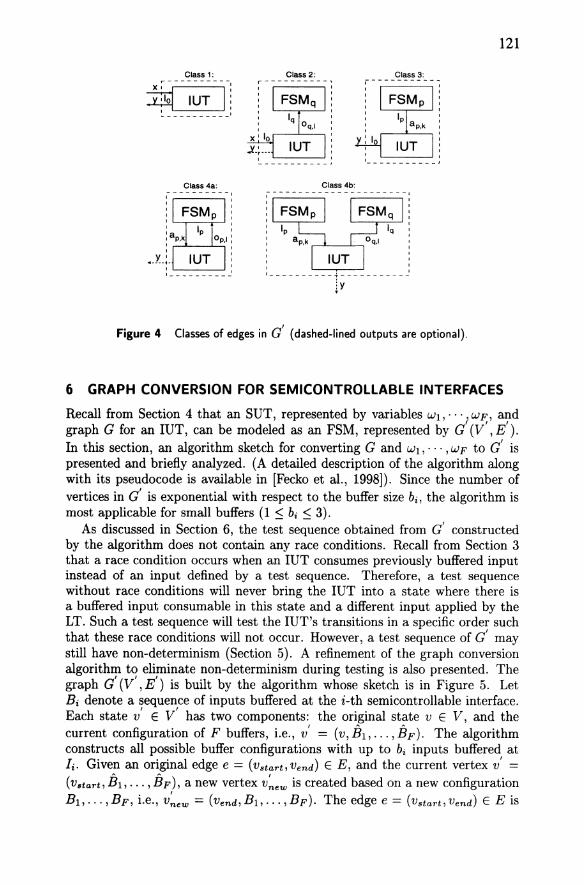
Figure 4 Classes of edges in a' (dashed-lined outputs are optional).
121
6 GRAPH CONVERSION FOR SEMICONTROLLABLE INTERFACES
Recall from Section 4 that an SUT, represented by variables WI, .. ·1 wF,' graph a for an IUT, can be modeled as an FSM, represented by a (V , E). rn this section, an algorithm sketch for converting a and Wl, ... , W F to c' is presented and briefly analyzed. (A detailed description of the algorithm along with its pseudocode is available in [Fecko et al., 1998]). Since the number of vertices in c' is exponential with respect to the buffer size bi , the algorithm is most applicable for small buffers (1 ::; bi ::; 3).
As discussed in Section 6, the test sequence obtained from GO constructed by the algorithm does not contain any race conditions. Recall from Section 3 that a race condition occurs when an rUT consumes previously buffered input instead of an input defined by a test sequence. Therefore, a test sequence without race conditions will never bring the rUT into a state where there is a buffered input consumable in this state and a different input applied by the LT. Such a test sequence will test the rUT's transitions in a specific order such that these race conditions will not occur. However, a test sequence of c' may still have non-determinism (Section 5). A refinement of the graph conversion algorithm to eliminate non-determinism during testing is also presented. The graph a' (V', E') is built by the algorithm whose sketch is in Figure 5. Let Bi denote a sequence of inputs buffered at the i-th semicontrollable interface. Each state v' E V' has two components: the original state v E V, and the current configuration of F buffers, i.e., v' = (v, ih, ... , iJp). The algorithm constructs all possible buffer configurations with up to bi inputs buffered at h Given an original edge e = (vstart,Vend) E E, and the current vertex v' = (V.tart, B 1 , . .. , BF), a new vertex is created based on a new configuration Bl, ... ,BF, i.e., = (vend,Bl,· ... ,BF). The edge e = (vstart,Vend) E E is

122
d(V',E) = BUILD-EXPANDED-GRAPH (G(V,E),r)
1. initialize r', root of G', as (r, 0,·· .. 0) (root of G and configuration of empty buffers)
2. initialize E as empty set, and V' as {r'}
3. initialize Q, queue of vertices, as V' 4. repeat until Q is empty
(a) extract v' = (vstart, th, ... , EF) as first element from Q, where (El, ... , EF) is current configuration
(b) for each outgoing edge e = (Vstart, Vend) E E do i. determine k, index of e's class
ii. given (El, ... , EF) and Class k definition, construct: • new configuration ·(Bl, ... , BF)
• new vertex = (vend, Bl, ... ,BF) E V' • new edge = (v', E E
(c) include new edges in E' iff inputs in (El, ... , EF) cannot trigger other edges outgoing from Vstart
(d) append to Q end vertices E V' of new edges included in E'
5. remove from V' all vertices from which r' cannot be reached
6. remove from E' all edges incident to such vertices
Figure 5 Algorithm sketch for converting graph a into a' .
included in E' as = (v' , The edge e E E belongs to one of the four classes depicted in Figure 4:
Class 1: e is triggered by an input from and generates output(s) to an LT. In this case, e's traversal does not modify the configuration (ih, ... ,BF) of e's start state. e is included in E' unconditionally.
Class 2: e is triggered by an input from an LT and generates an output Oq,1 at Iq. e is included in only when the number of inputs already buffered in Bq in the corresponding configuration of state (V.tart, Bl, ... ,BF) is smaller than the maximum allowable bq . The new configuration (B1, ... , B F) is obtained from (B1 , ••• ,BF) by appending aq,1 to Bq.
Class 3: e is triggered by ap,1c from Ip and generates output(s) to an LT. e is included in only when ap,k is the first element buffered in Bp in the corresponding configuration ofstate (V.tart, B 1 , ••• ,BF). The new configuration (B1 , •• . ,BF) is obtained from (B1 , ... , BF) by deleting ap,1c from Bp.
Class 4: e is triggered by an input ap,1c from Ip and generates an output Oq,1 at Iq. If e interacts with only one semicontrollable interface, i.e., p = q (Class 4a),
then it is included in only when e's input ap,k is the first element buffered in Bp in the corresponding configuration of state (V.tart,B1 , ••• ,BF). Since ap,1c is first deleted from Bp, there is always room in Bp for ap,l. If Ip and

123
Iq are different, i.e., p 1= q (Class 4b), then e is included in only when it satisfies the inclusion conditions for both Classes 3 and 2 edges, as 4efined above. The new configuration (B1 , ... , BF) is obtained from (B1 , •.. , BF) by applying rules for Classes 3 and 2 (in this order).
More complicated cases can be modeled as a combination of these four classes. For example, the case where an input x applied at 10 goes through IUT, FSMp , IUT, FSMq , and IUT, to produce an output y at 10 , can be a combination of Classes 2 and 3. The cases where FSMp and FSMq directly communicate with each other are beyond the scope of this paper.
It can be shown that a' (V' , E') built by the algorithm of Figure 5 is a minimal valid representation of the system defined by G and variables Wl,"·· ,WF [Fecko et al., 1998, Uyar et al., 1998]. The running time RT of the algorithm is shown [Fecko et al., 1998] to be:
if c > 1 if c = 1
Based on the practical considerations discussed in Section 5, the algorithm can be refined so that at any given point in time there could be a single input buffered in only one of the buffers Bi , which yields a linear running time of RTref = O(c * F * lEI).
7 TEST GENERATION FOR PRACTICAL TESTING ENVIRONMENT
Given graphs G(V, E) and G' (Vi, E'), our goal is to find a minimum-cost tour of a' such that each original edge from G is covered at least once. Recall from Section 5 that a' will likely contain multiple appearances of certain edges from the original graph G. Let E' be the subset of edges in a' such that each original edge in E is represented by at least one copy in To build a minimum-cost tour of G' covering each original edge in E is equivalent to finding a minimum-cost tour of a' that includes each transition in (the set of mandatory edges) at least once, and each transition in (E' - (the set of optional edges) zero or more times. This problem is known as the Rural Chinese Postman Problem [Lenstra and Kan, 1976].
The issue that arises in the case of multiple appearances of certain edges in a' is which copies should be included in Practical concerns discussed in Section 5 require that copies incident to nodes corresponding to configurations with empty buffers should be marked as mandatory. Note that when the buffer size in each semicontrollable interface is 1, each edge e that belongs to some Ui,j
or Ti,j will appear in a' only once, and therefore will be marked as mandatory. All other edges with a copy incident to the states in Vi whose second component is the configuration of empty buffers will be marked as mandatory in this copy. If no such copy exists, the edge will be marked as mandatory in all its copies with the presence of a buffered input. Therefore, each edge in E' will be marked as mandatory in one or more appearances.
[Aho et al., 1991) present a solution to the problem of finding a minimum-cost tour of a' (V' , E') covering subset of edges E'. The sufficient condition

124
no inputs buffered a,., buffered
a 2., buffered a,,2 buffered
Figure 6 Graph transformation applied to the graph of Figure 3. Mandatory and optional edges appear in solid and dashed lines. respectively.
for the existence of a polynomial-time solution is that E: induce a weaklyconnected spanning subgraph of a'. It can be easily shown that E: obtained in the manner described above is a weakly-connected subset of E' .
Example (cont'd): Consider the graph of Figure 3. After conversion to d (Figure 6), each state is replaced with at most four copies - each corresponding to the buffer configuration at a semicontrollable interface. Each edge e is annotated as e.x, where x = 0, I, 2,3, depending on the input buffered in the e.x's start state, as , , shown in Figure 6. Given graphs G and G , the sets E and E are as follows:
= =
{el,e2,e3,e4,e5,e6,e7,eS,e9,eI0,ell,eI2,eI3,eI4}
{e1.0, e2.2, e3.1, e4.3, e5.0, e5.3, e6.0, e6.3, e7.0, eS.O, e9.3,
eIO.O, elO.l, eI2.0, eI3.0, eI3.1, eI3.2, eI4.0, eI4.1}
To build the set of mandatory edges to be included in a test sequence, we adopt the approach discussed in Sections 5 and 7. In d, several edges appear multiple times: e5, e6, elO, e13, and e14. The edges in Figure 6 shown in solid are the mandatory edges that are incident to nodes that correspond to the case where both buffers are empty, i.e., e5.0, e6.0, elO.O, eI3.0, and eI4.0. The copies that can be traversed only when either buffer contains an input are shown in dashed line: e5.3, e6.3, elO.1, eI3.1, eI3.2, and eI4.1. These are the optional edges, which will be included in the test sequence only when necessary. In this example we have:
= {e1.0, e2.2, e3.1, e4.3, e5.0, e6.0, e7.0, eS.O, e9.3, elO.O, el1.2, el2.0, el3.0, el4.0} , ,
Given the above sets E and Ee , the Aho et al. technique gives the minimum-length test sequence for d shown in Table 2. Steps with (-+) indicate that an edge is tested in this step. Note that, for simplicity, the UIO sequences [Sabnani and Dahbura, 1988} are not included in this sequence.

125
Step Edge name Input from Output to
-+1 e14 LT?XI4 LT!YI4 -+2 e13 LT?XI3 LT!YI3 -+3 e5 LT?X5 LT!Y5 -+4 e8 LT?xs FSM1!OI,2 -+5 ell FSM1?al,2 LT!Yll -+6 el LT?Xl FSM1!OI,1 -+7 el0 LT?XIO LT!ylO -+8 e3 FSM1 ?al,l FSM2!02,1 -+9 e4 FSM2?a2,1 LT!Y4
-+ 10 e12 LT?XI2 FSM2!02,1 11 e5 LT?X5 LT!Y5
-+ 12 e9 FSM2?a2,1 LT!yg -+ 13 e7 LT?X7 FSMIlol,2 -+ 14 e2 FSM1?al,2 FSM1!OI,2
15 e13 LT?XI3 LT!YI3 16 ell FSM1 ?al,2 LT!Yll 17 e13 LT?XI3 LT!YI3
-+ 18 e6 LT?X6 LT!Y6
Table 2 Minimum-length test sequence for the IUT of Figure 3.
8 CONCLUSION
In this paper, a testing environment is considered where the IUT communicates with multiple entities with different degrees of controllability on generating inputs. The inputs that these entities apply to the IUT may be directly controllable, semicontrollable, or uncontrollable. This paper introduces a graph conversion algorithm that takes full advantage of the semicontrollable inputs while avoiding race conditions. In a test sequence of such a modified graph, semicontrollable inputs become controllable (where possible). Although, in general, the graph conversion results in an exponentially large number of nodes, practical considerations can make the converted graph size feasible.
Currently, this methodology is being applied to generate tests for MIL-STD I88-220B. Without utilizing the semicontrollable inputs, the number of testable transitions for MIL-STD I88-220B Class the Class A - Type 1 Service Datalink module is approximately 200. With the presented methodology, initial results show that the number of testable transitions increases to over 700, a coverage of more than 95% of the transitions defined in the specification.
References
[188-220B, 1998] 188-220B (1998). Military Standard - Interoperability Standard for Digital Message Device Subsystems (MIL-STD 188-220B).
[Aho et aI., 1991] Aho, A. V., Dahbura, A. T., Lee, D., and Uyar, M. U. (1991). An optimization technique for protocol conformance test generation based on UIO sequences and rural Chinese postman tours. IEEE Trans. on Communications, 39(11):1604-1615.

126
[Brinksma,1988] Brinksma, E. (1988). A theory for the derivation of tests. In Proc. IFIP Protocol Specification, Testing, and Verification, VIII. North-Holland, Amsterdam.
[Cavalli et al., 1996] Cavalli, A. R., Favreau, J. P., and Phallippou, M. (1996). Standardization of formal methods in conformance testing of communication protocols. Computer Networks and ISDN Systems, 29(1):3-14.
[Chan and Vuong, 1989] Chan, W. Y. and Vuong, S. T. (1989). An improved protocol test generation procedure based on UIOs. In Proc. ACM SIGCOMM.
[Davis et al., 1998] Davis, M. D., Sigal, R., and Weyuker, E. J. (1998). Computability, Complexity, and Languages: Fundamentals of Theoretical Computer Science. Academic Press.
[Fecko et al., 1997] Fecko, M. A., Amer, P. D., Sethi, A. S., Uyar, M. U., Dzik, T., Menell, R., and McMahon, M. (1997). Formal design and testing of MIL-STD 188-220A based on Estelle. In Proc. MILCOM'97, Monterey, California.
[Fecko et al., 1998] Fecko, M. A., Uyar, M. U., Sethi, A. S., and Amer, P. D. (1998). Embedded testing in systems with semicontrollable interfaces. Technical Report TR-98-18, CIS Dept., University of Delaware, Newark, DE.
[Fujiwara and v Bochmann, 1992] Fujiwara, S. and v Bochmann, G. (1992). Testing nondeterministic finite state machines. In Proc. IFIP 4th IWPTS. North-Holland, Amsterdam.
[Hopcroft and Ullman, 1979] Hopcroft, J. E. and Ullman, J. D. (1979). Introduction to Automata Theory, Lan9uages, and Computation. Addison-Wesley.
[IS9646, 1991] IS9646 (1991). ISO International Standard 9646: Conformance Testing Methodology and Framework. ISO, Information Technology - OSI, Geneva, Switzerland.
[IS08802-2, 1994] IS08802-2 (1994). International Standard ISO/IEC 8802-2, ANSI/IEEE Std. 802.2. ISO/IEC, 2nd edition.
[Lenstra and Kan, 1976] Lenstra, J. K. and Kan, A. H. G. R. (1976). On general routing problems. Networks, 6:273-280.
[Linn and Uyar, 1994] Linn, R. J. and Uyar, M. U. (1994). Conformance Testing Methodologies and Architectures for OSI Protocols. IEEE Compo Soc. Press, Los Alamitos, CA.
[Miller and Paul, 1994] Miller, R. E. and Paul, S. (1994). Structural analysis of protocol specifications and generation of maximal fault coverage conformance test sequences. IEEE/ACM Trans. on Networking, 2(5):457-470.
[Phalippou,1992] Phalippou, M. (1992). The limited power of testing. In Proc. IFIP 5th IWPTS. North-Holland, Amsterdam.
[Rafiq and Castanet, 1990] Rafiq, O. and Castanet, R. (1990). From conformance testing to interoperability testing. In Proc. IFIP 3rd IWPTS, pages 371-385, Washington, DC.
[Rayner, 1987] Rayner, D. (1987). OSI conformance testing. Computer Networks and ISDN Systems, 14(1):79-98.
[Sabnani and Dahbura, 1988] Sabnani, K. K. and Dahbura, A. T. (1988). A protocol test generation procedure. Computer Networks and ISDN Systems, 15:285-297.
[Sarikaya et al., 1987] Sarikaya, B., von Bochmann, G., and Cerny, E. (1987). A test design methodology for protocol testing. IEEE Trans. Software Engineering, 13(5):518-531.
[Timohovich, 1993] Timohovich, E. (1993). An approach to protocol entity model development for embedded testing. Automatic Control and Computer Sciences, 27(3):34-41.
[Tretmans, 1996] Tretmans, J. (1996). Conformance testing with labelled transitions systems: Implementation relations and test generation. Computer Networks and ISDN Systems, 29(1):49-79.
[Ural, 1992] Ural, H. (1992). Formal methods for test sequence generation. Computer Communications, 15(5):311-325.
[Uyar et al., 1998] Uyar, M. U., Fecko, M. A., Sethi, A. S., and Amer, P. D. (1998). Minimumcost solutions for testing protocols with timers. In Proc. IEEE Int'/ Performance, Computing, and Communications Conf., pages 346-354, Phoenix, AZ.
[Zeng et al., 1989] Zeng, H. X., Chanson, S. T., and Smith, B. R. (1989). On ferry clip approaches in protocol testing. Computer Networks and ISDN Systems, 17(2):77-88.