Embed Size (px)
Citation preview

[Jain*, 5(1): January, 2016] ISSN: 2277-9655
(I2OR), Publication Impact Factor: 3.785
http: // www.ijesrt.com © International Journal of Engineering Sciences & Research Technology
[448]
IJESRT INTERNATIONAL JOURNAL OF ENGINEERING SCIENCES & RESEARCH
TECHNOLOGY EARTHQUAKE ANALYSIS OF RC BUILDING USING CEMENT INFILL WITH
REGULAR AND IRREGULAR GEOMETRY Darshit Jain*, Saleem Akhtar, Aslam Hussain
Department of Civil Engineering, UIT (RGPV), Bhopal (MP).
ABSTRACT Reinforced concrete frame buildings have become common form of construction with masonry infills in urban and
semi urban areas in the world. The term infilled frame denotes a composite structure formed by the combination of a
moment resisting plane frame and infill walls. The infill masonry may be of brick, concrete blocks, or stones. In the
current practice of structural design in India infill walls are considered as non-structural elements and their strength
and stiffness contribution are neglected. The effect of infill panels on the response of reinforced concrete frames
subjected to seismic action is widely recognized and has been subject of numerous experimental and analytical
investigations over last five decades. The framed building behaves differently as compared to a bare framed building
(without any infill) or a fully infilled framed building under lateral load. A bare frame is much less stiffer than a fully
infilled frame; it resists the applied lateral load through frame action and shows well-distributed plastic hinges at
failure. In this study high rise buildings of regular and irregular geometry with 200 mm cement infill thickness under
earthquake zones-V with different infill positions are considered so as to evaluate the efficient building frame. These
are achieved by comparing the result with different parameter like moment, shear force, peak displacement and drift.
.
KEYWORDS: Infill structure, seismic zones, framed structure, moment, forces, drift, displacements, etc.
INTRODUCTION The most likely reason of neglecting the influence of infill walls is due to their complicated failure mode. While the
infill walls show brittle failure, the reinforced concrete sustains lateral loads over large post yield deformation.
Moreover past research works show that there is considerable improvement in the lateral load resisting capacity by
the addition of infill walls. Inclusion of stiffness and strength of infill walls in the building frames decreases the
fundamental time period compared to a bare frame and consequently increases the base shear demand and the design
forces in the beams and columns. This increased design forces in the beams and columns of the buildings are not
captured in the conventional bare frame analysis. An appropriate way to analyse the buildings is to model the strength
and stiffness of infill walls. Unfortunately, no guidelines are given in IS 1893: 2002 (Part-1) for modelling the infill
walls. As an alternative, a bare frame analysis is generally used that ignores the strength and stiffness of the infill
walls. Different types of analytical models based on the physical understanding of the overall behaviour of an infill
panels were developed over the years to simulate the behaviour of in filled frames. The elastic analysis based (Smith
and Carter, 1969), the plastic analysis based (Liauw and Kwan, 1983), and the ultimate load based (Saneinejad and
Hobbs, 1995) approaches are among them.
The presence of infill walls in buildings accounts for the following issues:
i) Increases the lateral stiffness of the building frame.
ii) Decreases the natural period of vibration.
iii) Increases the base shear.
iv) Increases the shear forces and bending moments in the columns.
It was observed by Merabi (1994), the brittle shear failure of the column on the windward side while investigating
the infilled frame structure which had strong infill panel and weak frame. He reported that the infill has significant
improvement on the lateral strength and stiffness of a bare frame and also significantly improves the energy dissipation
capability of the structure. Fardis (1996) investigated the seismic response of an infilled frame which had weak frames
with strong infill material. It was observe that the strong infill which was considered as non structural is responsible
for earthquake resistance of weak reinforced concrete frames. On the contrary, since infill is extensively used, it would

[Jain*, 5(1): January, 2016] ISSN: 2277-9655
(I2OR), Publication Impact Factor: 3.785
http: // www.ijesrt.com © International Journal of Engineering Sciences & Research Technology
[449]
be cost effective if positive effects of infill is utilised. Al-Chaar (1998) performed studies on the behaviour of
reinforced concrete frames with masonry infill. The test was conducted on two half scale specimens in which one of
the frames was stronger than the other. The stronger frame specimen showed diagonal tension cracking while the weak
frame failed because of diagonal cracking as well as hinging of the column at lower end. Both the frames were reported
to have shown the ductile behaviour but the extent of ductility is not specific. However, he concluded that the infill
wall improves the strength, stiffness and energy absorption capacity of the plane structures which are useful for
structures in seismic regions. Dominguez (2000) studied the effects of non-structural component on the fundamental
period of buildings. The model consists of five storeys, ten storeys and fifteen storeys with diagonal struts as the infill
(non-structural component). It was reported that the presence of infill decreases the fundamental period of the
structure. The trend of decrease in period with increase in thickness is decreasing with the increase in height.
Doudoumis (2006) studied the importance of contact condition between the infill and frame members on a single
storey finite element model. He reported that the interface condition, friction coefficient, size of mesh, relative stiffness
of beam to column, relative size of infill wall have significant influence on the response of infilled frame, while the
effect of orthotropy of infill material was reported to be insignificant. That means that the infill can be treated as
homogeneous material. When the mesh density was made finer the stress pattern within the infill was also improved,
with the maximum values of stresses at the compressive corners. The existence of friction coefficient at the interface
was reported to increase the lateral stiffness of the system. However, friction coefficient is dependent on the quality
of material and workmanship, which is difficult to define accurately. The response parameters were also increased
with the stiffness of frame and infill and the relative size of frame and infill plane. However, this study was conducted
for a single storey model under monotonic loading, therefore it is important to conduct similar studies for more number
of stories under earthquake load. Asokan (2006) studied how the presence of masonry infill walls in the frames of a
building changes the lateral stiffness and strength of the structure. This research proposed a plastic hinge model for
infill wall to be used in nonlinear performance based analysis of a building and concludes that the ultimate load (UL)
approach along with the proposed hinge property provides a better estimate of the inelastic drift of the building. J.
Dorji and D.P. Thambiratnam (2009) concluded that the strength of infill in terms of its Young’s Modulus (E) has
a significant influence on the global performance of the structure. The stresses in the infill wall decrease with increase
in (E) values due to increase in stiffness of the model. The stresses varies with building heights for a given E and
seismic hazard.
METHODOLOGY Significant analytical and experimental research is carried out since five decades, which attempts to understand the
behaviour of reinforced concrete frames with infill walls under earthquake loading. Various types of analytical models
based on the physical understanding of the overall behaviour of an infill frame were developed over the years to
simulate the behaviour of infilled frames.
In this study, the effect of cement brick infill wall on a reinforced concrete moment resisting frame under earthquake
loading is considered to determine the strength, stability and stiffness of building by varying infill arrangements like
without, inner, outer and full infill. Comparison is done with the help of various parameter like bending moment,
maximum displacement and storey displacement.
GEOMETRY
For present study 09 storey buildings are considered. The buildings are considered to have regular and irregular
geometry. Storey height is taken as 3 m each in all the floors and depth of foundation as 2 m. The building is kept
symmetric in both orthogonal directions in plan to avoid torsional response under lateral force. The column is kept
square and size of the column is kept same throughout the height of the structure to keep the discussion focussed only
on the infill and partially infill effect without getting distracted by the issues like orientation of column.
MODELLING
The building is considered to be located in seismic zone V intended for residential use. The building is observed on
medium strength soil through isolated footing under the columns. Response reduction factor for the special moment
resisting frame has taken as 5.0 (assuming ductile detailing). The floor finish on the floors is taken to be 1.0 kN/m2.
The live load on floor is been taken as 3.0 kN/m2. In seismic weight calculations, 25 % of the floor live loads are
considered in the analysis.

[Jain*, 5(1): January, 2016] ISSN: 2277-9655
(I2OR), Publication Impact Factor: 3.785
http: // www.ijesrt.com © International Journal of Engineering Sciences & Research Technology
[450]
Table 1: Details of Structure
Type of structure Residential building (G+8)
Total height of building 27 m
Height of each storey 3 m
Depth of foundation 2 m
Bay width in longitudinal direction 3 m
Bay width in transverse direction 3 m
Size of beams 230 mm X 450 mm
Size of columns 350 mm X 350 mm
Thickness of slab 150mm
Thickness of infill 200 mm
Infill material Cement
Seismic zone V
Soil condition Medium
Response reduction factor 5
Importance factor 1.5
Density of cement brick masonry 18.5 kN/m3
MODEL CONSIDERED FOR ANALYSIS The following are the models used for the analysis of work

[Jain*, 5(1): January, 2016] ISSN: 2277-9655
(I2OR), Publication Impact Factor: 3.785
http: // www.ijesrt.com © International Journal of Engineering Sciences & Research Technology
[451]
Fig. 1: Plan and elevation of the bare frame structure
Fig. 2: 3D view of the bare infill wall frame at without, full, inner and outer respectively
Fig.3: 3D view of the irregular plaza frame at without, full, inner and outer respectively

[Jain*, 5(1): January, 2016] ISSN: 2277-9655
(I2OR), Publication Impact Factor: 3.785
http: // www.ijesrt.com © International Journal of Engineering Sciences & Research Technology
[452]
Fig. 4: 3D view of the irregular stepped frame at without, full, inner and outer respectively
RESULTS Results for displacements, bending moment, shear force and storey displacement are given below. Results can be
described under following heads.
MAXIMUM DISPLACEMENT Maximum displacement has been found out with infill of cement brick whose details are given below
Maximum displacement in cement brick infill
Maximum displacement of cement brick infill in X and Z directions are shown below
Table 2: Maximum displacement in X and Z direction with cement brick infill
Infill
Max. displacement (mm)
Bare Frame Stepped Plaza
X Dir. Z Dir. X Dir. Z Dir. X Dir. Z Dir.
Without 121.59 121.59 112.53 119.73 127.75 127.75
Outer 34.17 34.17 34.21 25.52 31.19 31.19
Inner 23.03 23.03 24.99 23.85 16.89 16.18
Full 10.60 10.60 12.27 10.01 10.42 10.68
Fig. 5: Maximum displacement in X direction with cement brick infill
0.00
20.00
40.00
60.00
80.00
100.00
120.00
140.00
Without Outer Inner Full
Ma
x. D
isp
lace
me
nt
(mm
)
Infill
Bare Frame
Stepped
Plaza

[Jain*, 5(1): January, 2016] ISSN: 2277-9655
(I2OR), Publication Impact Factor: 3.785
http: // www.ijesrt.com © International Journal of Engineering Sciences & Research Technology
[453]
Fig. 6: Maximum displacement in Z direction with cement brick infill
Maximum displacement is observed in without infill plaza structure and minimum in full infill stepped structure in Z
direction
STOREY DISPLACEMENT Storey displacement has been found out with infill of cement brick whose details are given below
Storey displacement in cement brick infill
Storey displacement of cement brick infill X and Z direction are shown below
Table 3: Storey displacement in X and Z direction without infill
Storey
Storey disp. (mm)
Bare Frame Stepped Plaza
X Dir. Z Dir. X Dir. Z Dir. X Dir. Z Dir.
Base 0.00 0.00 0.00 0.00 0.00 0.00
GF 2.93 2.93 1.55 1.55 1.85 2.32
1st floor 12.75 12.75 6.89 6.89 9.14 10.13
2nd floor 23.26 23.26 17.67 17.67 17.19 18.64
3rd floor 33.73 33.73 29.84 29.84 25.10 27.37
4th floor 43.89 43.89 41.74 41.74 34.31 36.05
5th floor 53.45 53.45 53.05 53.05 43.42 44.43
6th floor 62.08 62.08 63.36 63.36 51.41 52.46
7th floor 69.40 69.40 72.24 72.24 59.79 60.61
8th floor 74.97 74.97 79.19 79.19 66.84 66.86
9th floor 78.45 78.45 83.78 83.78 71.41 70.65
0.00
20.00
40.00
60.00
80.00
100.00
120.00
140.00
Without Outer Inner FullMax
. Dis
pla
cem
ent
(mm
)
Infill
Bare Frame
Stepped
Plaza

[Jain*, 5(1): January, 2016] ISSN: 2277-9655
(I2OR), Publication Impact Factor: 3.785
http: // www.ijesrt.com © International Journal of Engineering Sciences & Research Technology
[454]
Fig. 7: Storey displacement without infill in X direction
Fig. 8: Storey displacement without infill in Z direction
Maximum storey displacement without infill is in stepped structure and minimum in plaza structure
Table 4: Storey displacement in X and Z direction with outer infill
Storey
Storey disp. (mm)
Bare Frame Stepped Plaza
X Dir. Z Dir. X Dir. Z Dir. X Dir. Z Dir.
Base 0.00 0.00 0.00 0.00 0.00 0.00
GF 5.42 5.42 3.81 0.99 2.09 2.09
1st floor 5.83 5.83 4.14 3.89 8.22 8.22
2nd floor 6.24 6.24 4.53 7.04 9.19 9.19
3rd floor 6.68 6.68 4.99 9.56 10.21 10.21
4th floor 7.13 7.13 5.58 11.20 11.31 11.31
5th floor 7.59 7.59 6.23 13.12 12.44 12.44
6th floor 8.05 8.05 6.86 16.07 13.58 13.58
0.0010.0020.0030.0040.0050.0060.0070.0080.0090.00
Max
. Sto
rey
Dis
pla
cem
ent
(mm
)
Floor
Bare Frame
Stepped
Plaza
0.00
20.00
40.00
60.00
80.00
100.00
Max
. Sto
rey
Dis
pla
cem
ent
(mm
)
Floor
Bare Frame
Stepped
Plaza
[Jain*, 5(1): January, 2016] ISSN: 2277-9655
(I2OR), Publication Impact Factor: 3.785
http: // www.ijesrt.com © International Journal of Engineering Sciences & Research Technology
[455]
7th floor 8.49 8.49 7.66 16.39 14.73 14.73
8th floor 8.91 8.91 8.42 16.64 15.86 15.86
9th floor 9.31 9.31 9.14 16.88 16.96 16.96
Fig. 9: Storey displacement with outer infill in X direction
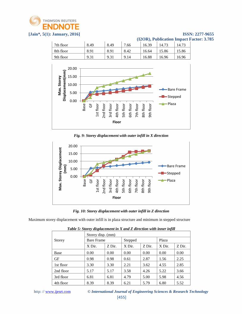
Fig. 10: Storey displacement with outer infill in Z direction
Maximum storey displacement with outer infill is in plaza structure and minimum in stepped structure
Table 5: Storey displacement in X and Z direction with inner infill
Storey
Storey disp. (mm)
Bare Frame Stepped Plaza
X Dir. Z Dir. X Dir. Z Dir. X Dir. Z Dir.
Base 0.00 0.00 0.00 0.00 0.00 0.00
GF 0.98 0.98 0.61 2.87 1.56 2.25
1st floor 3.30 3.30 2.21 3.62 4.55 2.85
2nd floor 5.17 5.17 3.58 4.26 5.22 3.66
3rd floor 6.81 6.81 4.79 5.00 5.98 4.56
4th floor 8.39 8.39 6.21 5.79 6.80 5.52
0.00
5.00
10.00
15.00
20.00
Bas
e
GF
1st
flo
or
2n
d f
loo
r
3rd
flo
or
4th
flo
or
5th
flo
or
6th
flo
or
7th
flo
or
8th
flo
or
9th
flo
or
Max
. Sto
rey
Dis
pla
cem
ent(
mm
)
Floor
Bare Frame
Stepped
Plaza
0.00
5.00
10.00
15.00
20.00
Bas
e
GF
1st
flo
or
2nd
flo
or
3rd
flo
or
4th
flo
or
5th
flo
or
6th
flo
or
7th
flo
or
8th
flo
or
9th
flo
or
Max
. Sto
rey
Dis
pla
cem
ent
(mm
)
Floor
Bare Frame
Stepped
Plaza

[Jain*, 5(1): January, 2016] ISSN: 2277-9655
(I2OR), Publication Impact Factor: 3.785
http: // www.ijesrt.com © International Journal of Engineering Sciences & Research Technology
[456]
5th floor 9.97 9.97 7.71 6.63 7.66 6.51
6th floor 11.55 11.55 9.19 7.50 8.56 7.53
7th floor 13.07 13.07 10.94 8.40 9.46 8.56
8th floor 14.41 14.41 12.57 9.31 10.36 9.57
9th floor 15.34 15.34 13.72 10.17 11.26 10.58
Fig. 11: Storey displacement with inner infill in X direction
Fig. 12: Storey displacement with inner infill in Z direction
Maximum storey displacement with inner infill is in bare frame and minimum in stepped structure
Table 6: Storey displacement in X and Z direction with full infill
Storey
Storey disp. (mm)
Bare Frame Stepped Plaza
X Dir. Z Dir. X Dir. Z Dir. X Dir. Z Dir.
Base 0.00 0.00 0.00 0.00 0.00 0.00
GF 3.33 3.33 2.19 2.88 1.93 1.90
0.002.004.006.008.00
10.0012.0014.0016.0018.00
Bas
e
GF
1st
flo
or
2nd
flo
or
3rd
flo
or
4th
flo
or
5th
flo
or
6th
flo
or
7th
flo
or
8th
flo
or
9th
flo
or
Max
. Sto
rey
Dis
pla
cem
ent
(mm
)
Floor
Bare Frame
Stepped
Plaza
0.002.004.006.008.00
10.0012.0014.0016.0018.00
Bas
e
GF
1st
flo
or
2nd
flo
or
3rd
flo
or
4th
flo
or
5th
flo
or
6th
flo
or
7th
flo
or
8th
flo
or
9th
flo
or
Max
. Sto
rey
Dis
pla
cem
ent
(mm
)
Floor
Bare Frame
Stepped
Plaza

[Jain*, 5(1): January, 2016] ISSN: 2277-9655
(I2OR), Publication Impact Factor: 3.785
http: // www.ijesrt.com © International Journal of Engineering Sciences & Research Technology
[457]
1st floor 3.65 3.65 2.48 3.16 1.99 2.01
2nd floor 4.00 4.00 2.82 3.44 2.46 2.50
3rd floor 4.37 4.37 3.20 3.75 2.97 3.03
4th floor 4.76 4.76 3.64 4.07 3.55 3.62
5th floor 5.17 5.17 4.13 4.41 4.16 4.26
6th floor 5.58 5.58 4.62 4.76 4.79 4.91
7th floor 5.98 5.98 5.19 5.11 5.43 5.57
8th floor 6.37 6.37 5.75 5.44 6.07 6.23
9th floor 6.76 6.76 6.30 5.76 6.68 6.87
Fig. 13: Storey displacement with full infill in X direction
Fig. 14: Storey displacement with full infill in Z direction
Maximum storey displacement with full infill is in bare frame and minimum in stepped structure
BENDING MOMENT Maximum bending moment of cement brick infill are shown below
0.00
2.00
4.00
6.00
8.00
Bas
e
GF
1st
flo
or
2nd
flo
or
3rd
flo
or
4th
flo
or
5th
flo
or
6th
flo
or
7th
flo
or
8th
flo
or
9th
flo
or
Max
. Sto
rey
Dis
pla
cem
ent
(mm
)
Floor
Bare Frame
Stepped
Plaza
0.00
2.00
4.00
6.00
8.00
Max
. Sto
rey
Dis
pla
cem
ent
(mm
)
Floor
Bare Frame
Stepped
Plaza

[Jain*, 5(1): January, 2016] ISSN: 2277-9655
(I2OR), Publication Impact Factor: 3.785
http: // www.ijesrt.com © International Journal of Engineering Sciences & Research Technology
[458]
Table 7: Maximum bending moment with cement and clay brick infill
Maximum bending moment (kNm)
Infill Bare Frame Stepped Plaza
Without 204.249 211.988 223.859
Outer 97.057 113.628 189.076
Inner 118.235 105.163 116.92
Full 31.132 78.78 45.754
Fig. 15: Maximum bending moment with cement brick infill
Maximum bending moment is in without infill plaza structure and minimum is in full infill bare frame
SHEAR FORCE
Maximum shear force of cement and clay brick infill are below
Table 8: Maximum shear force with cement brick infill
Maximum shear force (kN)
Infill Bare Frame Stepped Plaza
Without 139.738 145.379 149.561
Outer 75.459 76.219 123.891
Inner 72.802 61.757 73.15
Full 33.085 48.194 43.826
0
50
100
150
200
250
Without Outer Inner FullMax
. Ben
din
g M
om
ent
(kN
m)
Infill
Bare Frame
Stepped
Plaza

[Jain*, 5(1): January, 2016] ISSN: 2277-9655
(I2OR), Publication Impact Factor: 3.785
http: // www.ijesrt.com © International Journal of Engineering Sciences & Research Technology
[459]
Fig. 16: Maximum shear force with cement brick infill
Maximum shear force is in without infill plaza and minimum is in full bare frame
CONCLUSION The value of maximum displacement, storey displacement, maximum bending moment and maximum shear
force is observed highest in without infill structure and it is comparatively less in case of inner infill structure,
still less in outer infill structure and lowest in full infill structure.
It can be concluded from the study that the value of various distractive parameter namely maximum
displacement, storey displacement, maximum bending moment and maximum shear force Full infill is best
and efficient pattern because these parameter are lowest in this case further based on same line we can
conclude that inner infill and outer infill is second best and third best respectively whereas without infill
structure can be termed as critical structure.
If we consider irregular structure than plaza structure is more effective compared to other structure because
plaza structure shows lower parameters
Although the dead weight of the structure increases with infill but it increases the stiffness of the structure
which is an important factor in seismic design of structures
REFERENCES [1] Al-Chaar G., Issa M. and Sweeney S. 'Behaviour of masonry infilled non-ductile RC frames', ASCE Journal
of Structural Engineering. 128(8), 1055-1063. 1998
[2] Asokan A. 'Modelling of Masonry Infill Walls for Nonlinear Static Analysis under Seismic Loads', MS
Thesis. Indian Institute of Technology Madras, Chennai, 2006
[3] Dukuze A, 'Behaviour of reinforced concrete frames infilled with brick masonry panels', Canada, University
of New Brunswick (Canada), 2000
[4] Dominguez Morales M. (2000). Fundamental period of vibration for reinforced concrete buildings. Canada,
University of Ottawa (Canada).
[5] Doudoumis I.N. (2006). Finite element modelling and investigation of the behaviour of elastic infilled frames
under monotonic loading. Engineering Structures. 29(6),1004-1024.
[6] Fardis M.N. and Panagiotakos T. B. 'Seismic design and response of bare and masonry-infilled concrete
buildings', Journal of Earthquake Engineering. 1, 475-503,1996
[7] Kanitkar R. and Kanitkar V. (2004). Seismic performance of conventional multi-storey buildings with open
ground storey floors for vehicular parking. The Indian Concrete Journal. 78, 99-104.
0
20
40
60
80
100
120
140
160
Without Outer Inner Full
Max
. Sh
ear
Forc
e (
kN)
Infill
Bare Frame
Stepped
Plaza

[Jain*, 5(1): January, 2016] ISSN: 2277-9655
(I2OR), Publication Impact Factor: 3.785
http: // www.ijesrt.com © International Journal of Engineering Sciences & Research Technology
[460]
[8] Sattar S. and Abbie B. L. (2010). Seismic Performance of Reinforced Concrete Frame Structures with and
without Masonry Infill Walls, 9th U.S. National and 10th Canadian Conference on Earthquake Engineering,
Toronto, Canada.
[9] Scarlet A. (1997). Design of Soft Stories – A simplified energy approach. Earthquake Spectra. 13, 305-315.
[10] Smith S. B. (1962). Lateral Stiffness of Infilled Frames. ASCE Journal of the Structural Division. 88, 183-
199.
[11] S. B. Smith and Carter C. (1969). A Method of Analysis for Infilled Frames. Proceedings of Institution of
Civil Engineers. 44, 31-48.
[12] Subramanian N. (2004). Discussion on seismic performance of conventional multi-storey building with open
ground floors for vehicular parking by Kanitkar and Kanitkar. The Indian Concrete Journal. 78, 11-13.
[13] User's manual, STAAD.Pro software (2013).

![IJESRT /Archives-2015/September... · 2018-10-11 · [Gunje, 4(9): September, 2015] ISSN: 2277-9655 (I2OR), Publication Impact Factor: 3.785 http: // © International Journal of Engineering](https://img.dokumen.tips/doc/110x75/5f939c6f91986f2b0015ccfe/archives-2015september-2018-10-11-gunje-49-september-2015-issn.jpg)


![IJESRT /Archives-2015/May-2015/23_SOLUTIO… · [Jebaseelil, 4(5): May, 2015] ISSN: 2277-9655 (I2OR), Publication Impact Factor: 3.785 (ISRA), Impact Factor: 2.114 http: // © International](https://img.dokumen.tips/doc/110x75/5f5122a00290294bbe37f7ca/archives-2015may-201523solutio-jebaseelil-45-may-2015-issn-2277-9655.jpg)


![IJESRTijesrt.com/issues /Archive-2018/July-2018/39.pdfOxygen (DO) value as well as strong color [9]. Biological, Physico-chemical and Biochemical plant are mainly used for textile](https://img.dokumen.tips/doc/110x75/607f71ea1c57ec386871a6ed/archive-2018july-201839pdf-oxygen-do-value-as-well-as-strong-color-9-biological.jpg)


![IJESRT /Archive-2016/April-2016/68_EFFECT OF... · [Deepali*, 5(4): April, 2016] ISSN: 2277-9655 (I2OR), Publication Impact Factor: 3.785 http: // © International Journal of Engineering](https://img.dokumen.tips/doc/110x75/5b52380b7f8b9a7b648d0242/archive-2016april-201668effect-of-deepali-54-april-2016-issn.jpg)
![Nathan Jacobs · tent performance of deep learning models on mammogram classification. Journal of the American College of Radiology, 2020. Impact factor: 3.785. [4]Raian V. Maretto,](https://img.dokumen.tips/doc/110x75/5fbbebd21d0432329238b9bb/nathan-jacobs-tent-performance-of-deep-learning-models-on-mammogram-classiication.jpg)


![IJESRTijesrt.com/issues /Archives-2014/June-2014/76.pdf · http: // (C)International Journal of Engineering Sciences & Research Technology [492-506] alternative ingredient or material](https://img.dokumen.tips/doc/110x75/5e3d1d4cd064885c7d22e638/archives-2014june-201476pdf-http-cinternational-journal-of-engineering.jpg)