Embed Size (px)
Citation preview

[Trivedi*, 5(1): January, 2016] ISSN: 2277-9655
(I2OR), Publication Impact Factor: 3.785
http: // www.ijesrt.com © International Journal of Engineering Sciences & Research Technology
[539]
IJESRT INTERNATIONAL JOURNAL OF ENGINEERING SCIENCES & RESEARCH
TECHNOLOGY DEVELOPMENT OF INTERVAL TYPE-2 FUZZY BASED CONTROL MODEL AND
SIMULATION OF STEAM TURBINE GOVERNING SYSTEM OF POWER PLANT Ruchi Trivedi*, Manoj Kumar Jha, Shilpa Sharma, M.F.Qureshi
Department of Applied Mathematics, Rungta Engg. College, Raipur,India.
Department of Applied Mathematics, Rungta Engg. College, Raipur, India.
Department of Applied Chemistry, Rungta Engg. College, Raipur, India.
Department of Electrical Engg., Govt. Polytechnic college Narayanpur, India.
ABSTRACT The issue of power system stability is becoming more crucial. In deregulated power systems, competition could push
the system near its security limit. The governing controls of generator play an important role in improving the dynamic
and transient stability of power system. In this paper, we present an interval type-2 fuzzy logic based method for
governing control including efficient terminal voltage regulation. Interval type-2 Fuzzy logic is applied to generate
compensating signals to modify the controls during system disturbances. The oscillation of internal generator angles
is observed to indicate the good performance of proposed control scheme, very over a wide range. In this work,
development of Interval Type-2 Fuzzy based Model of steam turbine Governing System of Power Plant is proposed.
The power system transient terminal voltage and frequency stability enhancement have been well investigated and
studied through the following efforts.
Membership functions in interval type-2 fuzzy logic controllers are called footprint of uncertainty (FOU), which is
limited by two membership functions of adaptive network based fuzzy inference systems; they were upper
membership function (UMF) and lower membership function (LMF). The performances of the proposed controllers
were evaluated and discussed on the basis of the simulation results. An experiment set up of power system governing
system was built and used to verify the performance of IT-2FLC controller.
.
KEYWORDS: Steam Turbine, Governing System Control, Interval Type-2 Fuzzy Logic Controller, Foot Print of
Uncertainty, Internal Generator Angle, PID Controller.
INTRODUCTION Governing system is an important control system in the power plant as it regulates the turbine speed, power and
participates in the grid frequency regulation. For starting, loading governing system is the main operator interface.
Steady state and dynamic performance of the power system depends on the power plant response capabilities in which
governing system plays a key role. With the development of electro- hydraulic governors, processing capabilities have
been enhanced but several adjustable parameters have been provided. A thorough understanding of the governing
process is necessary for such adjustment. The role of governing system in frequency control is also discussed. Power
system stability issue has been studied widely. Generator control is one of the most widely applied in the power
industry. This typically includes governing and excitation control. Fuzzy set theory has been widely used in the control
area with some application to power systems. A simple fuzzy control is built up by a group of rules based on the
human knowledge of system behaviour in power engineering area, fuzzy set theory is applied in power system control,
planning and some other aspects. Fuzzy logic has also been applied to design power system stabilizers. Governing
system behaviour is neglected in the design of excitation control. Part of the reason is the slow response of governing
systems compared with the exciting system. However proper control of governing system is helpful in damping system
oscillation and improving the transient stability.
Power system stability can be defined as the tendency of power system to react to disturbances by developing restoring
forces equal to or greater than the disturbing forces to maintain the state of equilibrium (synchronism). Stability
problems are therefore concerned with the behavior of the Synchronous Generator (SG) after they have been perturbed.

[Trivedi*, 5(1): January, 2016] ISSN: 2277-9655
(I2OR), Publication Impact Factor: 3.785
http: // www.ijesrt.com © International Journal of Engineering Sciences & Research Technology
[540]
Generally, there are three main categories of stability analysis. They are namely steady state stability, transient stability
and dynamic stability. Steady state stability is defined as the capability of the power system to maintain synchronism
after a gradual change in power caused by small disturbances. Transient state stability refers to as the capability of a
power system to maintain synchronism when subjected to a severe and sudden disturbance. The third category of
stability, which is the dynamic stability is an extension of steady state stability, it is concerned with the small
disturbances lasting long period of time. The generators are usually connected to an infinite bus where the terminal
voltages (Vt) are held at a constant value. The study of SG control systems can roughly be divided into two main
parts: voltage regulation and speed governing. Both of these control elements contribute to the stability of the machine
in the presence of per durations. There are various methods of controlling a SG and suitability will depend on the type
of machine, its application and the operating conditions. The governing controls of the generator play an important
role in improving the dynamic stability of the power system. The presence of poorly damped modes of oscillation,
and continuous variation in power system operating conditions arises some limitations in the conventional controllers.
These limitations have motivated research into so-called intelligent control systems. Artificial Neural Networks
(ANNs) have been used in the design of nonlinear adaptive controllers with various control objectives in the field of
electrical power engineering, especially for the synchronous generator excitation and governor control.
Here we present development of Interval Type-2 Fuzzy based Control Model of steam turbine Governing System and
excitation system of Power Plant, which compensates their control, inputs during faults. Two separate Interval Type-
2 Fuzzy controllers have been developed to address both the damping of frequency deviation and terminal voltage
oscillation problems. To present complete comparative analysis of the proposed control strategy with conventional
PID controller, two separate fluctuations scenario have been employed. SIMULINK simulation model is built to study
the dynamic behavior of conventional PID controlled synchronous machine and the performance of proposed
controller.
The Interval Type-2 Fuzzy Logic Controller (IT2FLC) is credited with being an adequate methodology for designing
robust controllers that are able to deliver a satisfactory performance in applications where the inherent uncertainty
makes it difficult to achieve good results using traditional methods. As a result the IT2FLC has become a popular
approach to mobile robot control in recent years. There are many sources of uncertainty facing the IT2FLC for power
system governing control; we list some of them as follows:
(a) Uncertainties in inputs to the IT2FLC which translate to uncertainties in the antecedent Membership
Functions (MFs) as the sensor measurements are typically noisy and are affected by the conditions of observation (i.e.
their characteristics are changed by the environmental conditions such as wind, sunshine, humidity, rain, etc.).
(b) Uncertainties in control outputs which translate to uncertainties in the consequent MFs of the IT2FLC.
Such uncertainties can result from the change of the actuators characteristics which can be due to wear, tear,
environmental changes, etc.
(c) Linguistic uncertainties as the meaning of words that are used in the antecedent and consequent linguistic
labels can be uncertain - words mean different things to different people. In addition, experts do not always agree and
they often provide different consequents for the same antecedents. A survey of experts will usually lead to a histogram
of possibilities for the consequent of a rule; this histogram represents the uncertainty about the consequent of a rule.
(d) Uncertainties associated with the use of noisy training data that could be used to learn, tune or optimize
the IT2FLC. While traditionally, type- 1 FLCs have been employed widely in governing system control, it has become
apparent in recent years that the type-1 FLC cannot fully handle high levels of uncertainties as its MFs are in fact
completely crisp. The linguistic and numerical uncertainties associated with dynamic unstructured environments cause
problems in determining the exact and precise MFs during the governing control IT2FLC design. Consequently,
research has started to focus on the possibilities of higher order FLCs, such as interval type-2 FLCs that use interval
type-2 fuzzy sets.
A traditional, type-1 FLC is not completely fuzzy, as the boundaries of its membership functions are fixed. This
implies that there may be unforeseen traffic scenarios for which the existing membership functions do not suffice to
model the uncertainties in the governing system control task. An IT2FLC can address this problem by extending a
Footprint-of-Uncertainty (FOU) on either side of an existing type-1 membership function. In IT2, fuzzy logic the
variation is assumed constant across the FOU, Hence the designation ‘interval’. The firstIT2 controllers are now

[Trivedi*, 5(1): January, 2016] ISSN: 2277-9655
(I2OR), Publication Impact Factor: 3.785
http: // www.ijesrt.com © International Journal of Engineering Sciences & Research Technology
[541]
emerging, in which conversion or retyping from fuzzy IT2 to fuzzy type-1 takes place before output. Not only does
such a controller bring confidence that re-tuning will not be needed for when arriving traffic displays un-anticipated
or un-modeled behavior but the off-line training period required to form the membership functions can be reduced.
This paper extends an existing FLC for governing system control to an IT2FLC and compares the performances in the
presence of measurement noise, which is artificially injected to test the relative robustness. Encouragingly, the
governing response is equivalent to the successful type-1 FLC when the measurement noise is limited and under test
results in a considerable improvement when the perturbations are large. This research is focused mainly on voltage
and frequency stability of SG in a typical power system using fourth order model of synchronous generator.
MODELING OF SYNCHRONOUS GENERATOR The overall accuracy of the power system stability is primarily decided by how correctly the Synchronous Generators
within the system are modeled. The proposed simulation model is developed as a fourth order machine time constants
in order to improve the terminal voltage and frequency deviation responses [5]. With proper modeling of the
synchronous machine in the power system, a better understanding of how the machine reacts under sudden large
disturbances during transient conditions can be achieved and hence a better power system voltage regulator and
governor controllers of the SG can be designed.
Some assumptions were taken into consideration and made prior to the design of the simulation model, these
assumptions are:
The SG turbine in this model produce a constant torque with a constant speed maintained during steady state
operation.
The SG output terminals are connected to infinite bus bar that has various load changes.
Only basic and linear models of the power system components will be used.
All the time constants of the SG which are used in this model of all components are assumed to be the
optimum time constants extracted based on the values given in Walton [5].
The stability of a SG depends on the inertia constant and the angular momentum. The rotational inertia equations
describe the effect of unbalance between electromagnetic torque and mechanical torque of individual machines. By
having small perturbation and small deviation in speed, the swing equation becomes [1]:
1
2m e
d wP P
dt H
….. (1)
Then d w d
dt dt
Where H = inertia constant, Pm= change in mechanical power, Pe = change in electrical power, ω =
change in speed (electrical rad/sec), δ = rotor angle (rad.)
Using Laplace Transformation, equation (1) becomes:
1
( ) (s) (s) ( )2
m es w P P sHs
….. (2)
A more appropriate way to describe the swing equation is to include a damping factor that is not accounted for in the
calculation of electrical power Pe. Therefore, a term proportional to speed deviation should be included. The speed
load characteristic of a composite load describing such issue is approximated by [6]:
e L DP P K w ….. (3)
[Trivedi*, 5(1): January, 2016] ISSN: 2277-9655
(I2OR), Publication Impact Factor: 3.785
http: // www.ijesrt.com © International Journal of Engineering Sciences & Research Technology
[542]
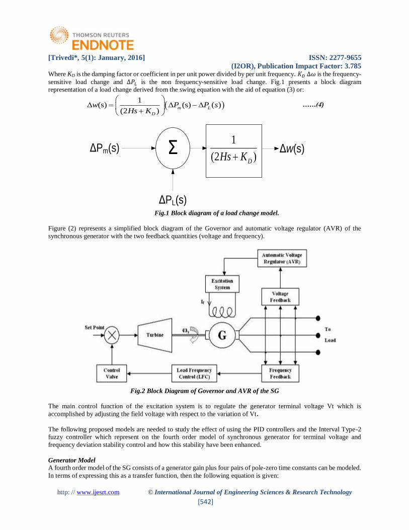
Where KD is the damping factor or coefficient in per unit power divided by per unit frequency. 𝐾𝐷 ∆𝜔 is the frequency-
sensitive load change and ∆𝑃𝐿 is the non frequency-sensitive load change. Fig.1 presents a block diagram
representation of a load change derived from the swing equation with the aid of equation (3) or:
1
(s) (s) ( )(2 )
m L
D
w P P sHs K
……(4)
ΔPm(s)
ΔPL(s)
Ʃ1
(2 )DHs KΔw(s)
Fig.1 Block diagram of a load change model.
Figure (2) represents a simplified block diagram of the Governor and automatic voltage regulator (AVR) of the
synchronous generator with the two feedback quantities (voltage and frequency).
Fig.2 Block Diagram of Governor and AVR of the SG
The main control function of the excitation system is to regulate the generator terminal voltage Vt which is
accomplished by adjusting the field voltage with respect to the variation of Vt.
The following proposed models are needed to study the effect of using the PID controllers and the Interval Type-2
fuzzy controller which represent on the fourth order model of synchronous generator for terminal voltage and
frequency deviation stability control and how this stability have been enhanced.
Generator Model
A fourth order model of the SG consists of a generator gain plus four pairs of pole-zero time constants can be modeled.
In terms of expressing this as a transfer function, then the following equation is given:

[Trivedi*, 5(1): January, 2016] ISSN: 2277-9655
(I2OR), Publication Impact Factor: 3.785
http: // www.ijesrt.com © International Journal of Engineering Sciences & Research Technology
[543]
......(5)
There are two ways in MATLAB Simulink to design the machine model, these are:
1. Using power system block set which is a set of ready-made [4].
2. Using blocks of transfer functions of the machine to manipulate the design model.
However, using blocks of the transfer function to represent the components in the power system is capable of having
higher order machine time constants as inputs. This can be achieved by the illustration shown in Figure (6.3) [8, 9].
VF(s) 1
1
(1 )
(1 )
z
p
sT
sT
KG
2
2
(1 )
(1 )
z
p
sT
sT
3
3
(1 )
(1 )
z
p
sT
sT
4
4
(1 )
(1 )
z
p
sT
sT
Vt(s)
Fig.3 Block diagram representing a 4th order SG time constants model
Where: KG = Gain of the generator, Tz = Time constant of the zero, Tp = Time constant of the pole, VF = Field voltage
of the SG, Vt = Terminal voltage of the SG.
Exciter model The most basic form of expressing the exciter model can be represented by a gain KE and a single time constant TE :
VF(s) / VR(s) = KE / (1 + sTE) ….. (6)
VR = the output voltage of the regulator (AVR), VF = field voltage
The excitation system amplifier is represented similarly by a gain KA and a time constant TA. The transfer function
of the amplifier is:
VR(s)/ ΔVe(s)= KA / (1+ sTA) ……(7)
Where: ΔVe = Voltage error = reference voltage (Vref ) - output voltage of the sensor(VS).
Sensor Model
The terminal voltage of the SG is being fed back by using a potential transformer that is connected to the bridge
rectifiers. The sensor is also being modeled, likewise as the exciter:
VS(s) / Vt(s) = KR / (1 + sTR) ...... (8)
VS = output voltage of the sensor, KR and TR are the gain and time constant of the sensor.
Automatic Voltage Regulator
In most modern systems, the AVR is a controller that senses the generator output voltage then initiates corrective
action by changing the exciter control in the desired direction [10]. A simple AVR is created with a 1st order model
of SG as shown in the Fig.4.
[Trivedi*, 5(1): January, 2016] ISSN: 2277-9655
(I2OR), Publication Impact Factor: 3.785
http: // www.ijesrt.com © International Journal of Engineering Sciences & Research Technology
[544]
Vref(s)(1 )
A
A
K
sT (1 )
E
E
K
sT (1 )
G
G
K
sTVt(s)
ΔVe(s) VR(s) VE(s)
(1 )
R
R
K
sT
+
-Amplifier Exciter Generator
Sensor
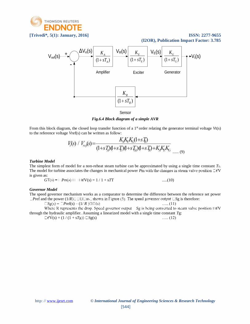
Fig.6.4 Block diagram of a simple AVR
From this block diagram, the closed loop transfer function of a 1st order relating the generator terminal voltage Vt(s)
to the reference voltage Vref(s) can be written as follow:
...... (9)
Turbine Model
The simplest form of model for a non-reheat steam turbine can be approximated by using a single time constant TT.
The model for turbine associates the changes in mechanical power P €V
is given as:
G P €V(s) = 1 / 1 + sTT .....(10)
Governor Model
The speed governor mechanism works as a comparator to determine the difference between the reference set power
Pref and the power (1/R Sg is therefore:
S Pref(s) – (1/ R ….. (11)
S €V
through the hydraulic amplifier. Assuming a linearized model with a single time constant Tg:
€V(s) = (1 / (1 + sT Sg(s) ….. (12)

[Trivedi*, 5(1): January, 2016] ISSN: 2277-9655
(I2OR), Publication Impact Factor: 3.785
http: // www.ijesrt.com © International Journal of Engineering Sciences & Research Technology
[545]
The final simulation model for a 4th order SG can be developed in "Matlab" as shown in Fig.5.
Fig.5 Simulation model for the 4th order synchronous generator time constants
Typically the excitation control and governing control are designed independently since there is a weak coupling
between them, then the voltage and frequency controls are regulated separately. The suggested conventional PID
controller and proposed interval type-2 fuzzy controller that can be used to enhance the output response of the AVR
in the excitation system is differing from the conventional PID controller and proposed interval type-2 fuzzy controller
that can be used to enhance the frequency deviation in the governing system.
PID Controller
The PID is a common sense approach to control based on the nature of error. It can be applied to wide varieties of
systems. The most applications of the PID controllers in power system control are in the control circuits of power
generation control the load angle variation and stability of the power system, or as an auxiliary regulating controller
inserting in the Excitation Control System together with the AVR to control and enhance the terminal voltage transient
stability response.
The three parameters that must be determined (some times, must be optimized) for the given process, to give the
desirable output responses for the plant are: proportional gain, integral gain and derivative gain. The transfer function
of the PID controller looks like the following :
C(s) = Kp +Ki / s + Kd s = (Kd s2 + Kp s + Ki) /s ….(13)
the PID controller, and the controller computes both the derivative and the integral of this error signal. The signal (u)
just past the controller is given as:
u= Kp.e +Ki ∫e.dt + Kd de/dt ….. (14)
[Trivedi*, 5(1): January, 2016] ISSN: 2277-9655
(I2OR), Publication Impact Factor: 3.785
http: // www.ijesrt.com © International Journal of Engineering Sciences & Research Technology
[546]
This signal will be sent to the plant, and the new output (y) will be obtained. This new output (y) will be sent back to
the sensor again to find the new error signal (e). The controller takes this new error signal and computes its derivative
and its integral again. This process will continuous until the desired output achieved.
A proportional controller (Kp) will have the effect of reducing the rise time and will reduce, but never eliminate, the
steady –state error. An integral control (Ki) will have the effect of eliminating the steady – state error, but it may make
the transient response worse.
A derivative control (Kd) will have the effect of increasing the stability of the system, reducing the overshoot, and
improving the transient response.
Two PID controllers are introduced in this research; one of them is introduced in the excitation system and the other
PID controller is introduced in the governing system. These PID controllers are developed to improve the dynamic
response and also reduce the steady state error.
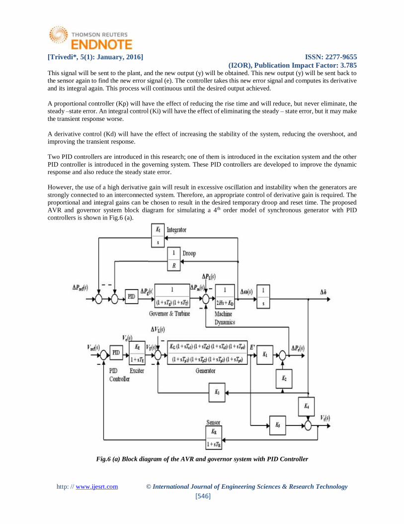
However, the use of a high derivative gain will result in excessive oscillation and instability when the generators are
strongly connected to an interconnected system. Therefore, an appropriate control of derivative gain is required. The
proportional and integral gains can be chosen to result in the desired temporary droop and reset time. The proposed
AVR and governor system block diagram for simulating a 4th order model of synchronous generator with PID
controllers is shown in Fig.6 (a).
Fig.6 (a) Block diagram of the AVR and governor system with PID Controller
[Trivedi*, 5(1): January, 2016] ISSN: 2277-9655
(I2OR), Publication Impact Factor: 3.785
http: // www.ijesrt.com © International Journal of Engineering Sciences & Research Technology
[547]
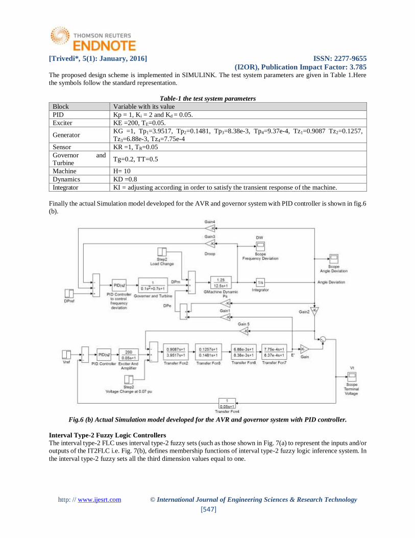
The proposed design scheme is implemented in SIMULINK. The test system parameters are given in Table 1.Here
the symbols follow the standard representation.
Table-1 the test system parameters
Block Variable with its value
PID Kp = 1, Ki = 2 and Kd = 0.05.
Exciter KE =200, TE=0.05.
Generator KG =1, Tp1=3.9517, Tp2=0.1481, Tp3=8.38e-3, Tp4=9.37e-4, Tz1=0.9087 Tz2=0.1257,
Tz3=6.88e-3, Tz4=7.75e-4
Sensor KR =1, TR=0.05
Governor and
Turbine Tg=0.2, TT=0.5
Machine H= 10
Dynamics KD =0.8
Integrator KI = adjusting according in order to satisfy the transient response of the machine.
Finally the actual Simulation model developed for the AVR and governor system with PID controller is shown in fig.6
(b).
Fig.6 (b) Actual Simulation model developed for the AVR and governor system with PID controller.
Interval Type-2 Fuzzy Logic Controllers
The interval type-2 FLC uses interval type-2 fuzzy sets (such as those shown in Fig. 7(a) to represent the inputs and/or
outputs of the IT2FLC i.e. Fig. 7(b), defines membership functions of interval type-2 fuzzy logic inference system. In
the interval type-2 fuzzy sets all the third dimension values equal to one.

[Trivedi*, 5(1): January, 2016] ISSN: 2277-9655
(I2OR), Publication Impact Factor: 3.785
http: // www.ijesrt.com © International Journal of Engineering Sciences & Research Technology
[548]
Fig.7 (a) an interval type-2 fuzzy set
Fig.7 (b) Structure of the interval type-2 FLC
The use of interval type-2 FLC helps to simplify the computation (as opposed to the general type-2 FLC which is
computationally intensive) which will enable the design of aIT2 FLC that operates in real time. The structure of an
interval type-2 FLC is depicted in Fig.7 (b), it consists of a Fuzzifier, Inference Engine, Rule Base, Type-Reducer and
a Defuzzifier. It has been argued that using interval type-2 fuzzy sets to represent the inputs and/or outputs of FLCs
has many advantages when compared to type-1 fuzzy sets; we summarize some of these advantages as follows:
(a) As the type-2 fuzzy set membership functions are themselves fuzzy and contain a footprint of uncertainty,
they can model and handle the linguistic and numerical uncertainties associated with the inputs and outputs of the
FLC. Therefore, FLCs that are based on interval type-2 fuzzy sets will have the potential to produce a better
performance than type-1 FLCs when dealing with uncertainties.
(b) Using interval type-2 fuzzy sets to represent the FLC inputs and outputs will result in the reduction of the
FLC rule base when compared to using type-1 fuzzy sets as the uncertainty represented in the footprint of uncertainty
in interval type-2 fuzzy sets lets us cover the same range as type-1 fuzzy sets with a smaller number of labels. The
rule reduction will be greater as the number of the FLC inputs increases.
(c) Each input and output will be represented by a large number of type-1 fuzzy sets which are embedded in
the type-2 fuzzy sets. The use of such a large number of type-1 fuzzy sets to describe the input and output variables
allows for a detailed description of the analytical control surface as the addition of the extra levels of classification
gives a much smoother control surface and response. According to Karnik and Mendel, the type-2 FLC can be thought
of as a collection of many different embedded type-1 FLCs.
(d) It can be seen that the extra degrees of freedom provided by the footprint of uncertainty enables a type-2
FLC to produce outputs that cannot be achieved by type-1 FLCs with the same number of membership functions. It
[Trivedi*, 5(1): January, 2016] ISSN: 2277-9655
(I2OR), Publication Impact Factor: 3.785
http: // www.ijesrt.com © International Journal of Engineering Sciences & Research Technology
[549]
has also been shown that a type-2 fuzzy set may give rise to an equivalent type-1 membership grade that is negative
or larger than unity.
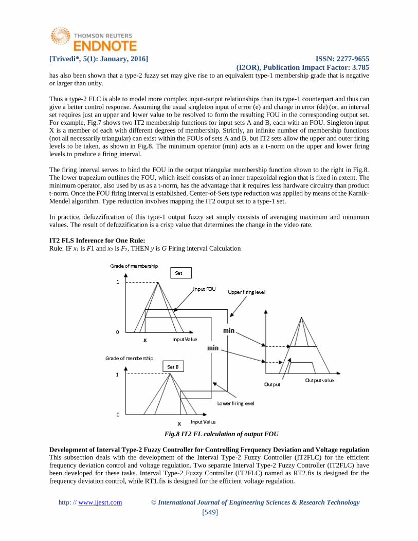
Thus a type-2 FLC is able to model more complex input-output relationships than its type-1 counterpart and thus can
give a better control response. Assuming the usual singleton input of error (e) and change in error (de) (or, an interval
set requires just an upper and lower value to be resolved to form the resulting FOU in the corresponding output set.
For example, Fig.7 shows two IT2 membership functions for input sets A and B, each with an FOU. Singleton input
X is a member of each with different degrees of membership. Strictly, an infinite number of membership functions
(not all necessarily triangular) can exist within the FOUs of sets A and B, but IT2 sets allow the upper and outer firing
levels to be taken, as shown in Fig.8. The minimum operator (min) acts as a t-norm on the upper and lower firing
levels to produce a firing interval.
The firing interval serves to bind the FOU in the output triangular membership function shown to the right in Fig.8.
The lower trapezium outlines the FOU, which itself consists of an inner trapezoidal region that is fixed in extent. The
minimum operator, also used by us as a t-norm, has the advantage that it requires less hardware circuitry than product
t-norm. Once the FOU firing interval is established, Center-of-Sets type reduction was applied by means of the Karnik-
Mendel algorithm. Type reduction involves mapping the IT2 output set to a type-1 set.
In practice, defuzzification of this type-1 output fuzzy set simply consists of averaging maximum and minimum
values. The result of defuzzification is a crisp value that determines the change in the video rate.
IT2 FLS Inference for One Rule:
Rule: IF x1 is F1 and x2 is F2, THEN y is G Firing interval Calculation
Fig.8 IT2 FL calculation of output FOU
Development of Interval Type-2 Fuzzy Controller for Controlling Frequency Deviation and Voltage regulation
This subsection deals with the development of the Interval Type-2 Fuzzy Controller (IT2FLC) for the efficient
frequency deviation control and voltage regulation. Two separate Interval Type-2 Fuzzy Controller (IT2FLC) have
been developed for these tasks. Interval Type-2 Fuzzy Controller (IT2FLC) named as RT2.fis is designed for the
frequency deviation control, while RT1.fis is designed for the efficient voltage regulation.
[Trivedi*, 5(1): January, 2016] ISSN: 2277-9655
(I2OR), Publication Impact Factor: 3.785
http: // www.ijesrt.com © International Journal of Engineering Sciences & Research Technology
[550]
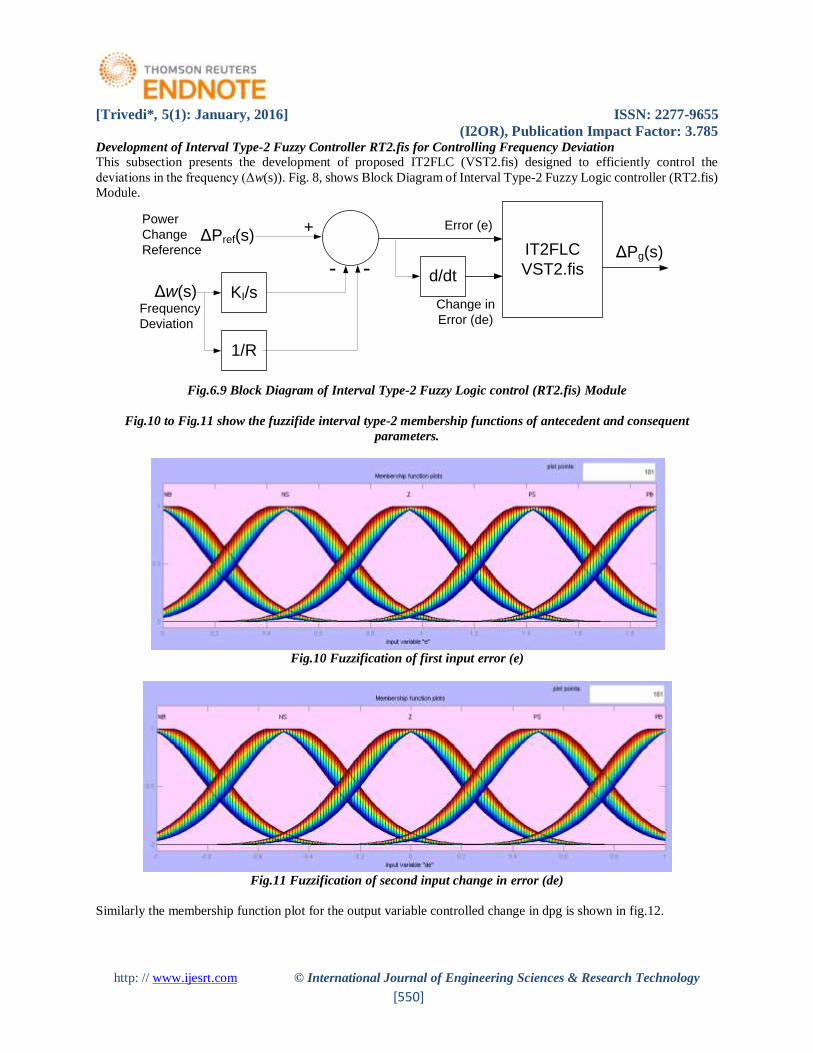
Development of Interval Type-2 Fuzzy Controller RT2.fis for Controlling Frequency Deviation
This subsection presents the development of proposed IT2FLC (VST2.fis) designed to efficiently control the
deviations in the frequency (Δw(s)). Fig. 8, shows Block Diagram of Interval Type-2 Fuzzy Logic controller (RT2.fis)
Module.
ΔPref(s)
KI/s
ΔPg(s)
+
-Δw(s)
1/R
- d/dt
IT2FLC
VST2.fis
Error (e)
Change in
Error (de)Frequency
Deviation
Power
Change
Reference
Fig.6.9 Block Diagram of Interval Type-2 Fuzzy Logic control (RT2.fis) Module
Fig.10 to Fig.11 show the fuzzifide interval type-2 membership functions of antecedent and consequent
parameters.
Fig.10 Fuzzification of first input error (e)
Fig.11 Fuzzification of second input change in error (de)
Similarly the membership function plot for the output variable controlled change in dpg is shown in fig.12.

[Trivedi*, 5(1): January, 2016] ISSN: 2277-9655
(I2OR), Publication Impact Factor: 3.785
http: // www.ijesrt.com © International Journal of Engineering Sciences & Research Technology
[551]
Fig.12 Membership function plot of the output variable dpg.
The rule base designed for the Interval Type-2 Fuzzy Logic controller (RT2.fis) Module is:
1. If (e is NB) and (de is NB) then (dpg is NB) (1)
2. If (e is NB) and (de is NS) then (dpg is NB) (1)
3. If (e is NB) and (de is Z) then (dpg is NB) (1)
4. If (e is NB) and (de is PS) then (dpg is PS) (1)
5. If (e is NB) and (de is PB) then (dpg is Z) (1)
6. If (e is NS) and (de is NB) then (dpg is NB) (1)
7. If (e is NS) and (de is NS) then (dpg is NB) (1)
8. If (e is NS) and (de is Z) then (dpg is NS) (1)
9. If (e is NS) and (de is PS) then (dpg is Z) (1)
10. If (e is NS) and (de is PB) then (dpg is PS) (1)
11. If (e is Z) and (de is NB) then (dpg is NB) (1)
12. If (e is Z) and (de is NS) then (dpg is NS) (1)
13. If (e is Z) and (de is Z) then (dpg is Z) (1)
14. If (e is Z) and (de is PS) then (dpg is PS) (1)
15. If (e is Z) and (de is PB) then (dpg is PB) (1)
16. If (e is PS) and (de is NB) then (dpg is NS) (1)
17. If (e is PS) and (de is NS) then (dpg is Z) (1)
18. If (e is PS) and (de is Z) then (dpg is PS) (1)
19. If (e is PS) and (de is PS) then (dpg is PB) (1)
20. If (e is PS) and (de is PB) then (dpg is PB) (1)
21. If (e is PB) and (de is NB) then (dpg is Z) (1)
22. If (e is PB) and (de is NS) then (dpg is NB) (1)
23. If (e is PB) and (de is Z) then (dpg is Z) (1)
24. If (e is PB) and (de is PS) then (dpg is Z) (1)
25. If (e is PB) and (de is PB) then (dpg is PS) (1)
During rule base and membership function designing the short terms stands as: NB = Negative Big, NS = Negative
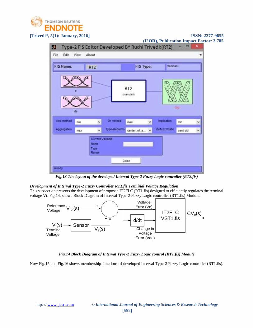
Small, Z = Zero Error, PS = Positive Small and PB = Positive Big. Finally the layout of the developed Interval Type-
2 Fuzzy Logic controller (RT2.fis), for controlling deviation in frequency is shown in fig.13.
[Trivedi*, 5(1): January, 2016] ISSN: 2277-9655
(I2OR), Publication Impact Factor: 3.785
http: // www.ijesrt.com © International Journal of Engineering Sciences & Research Technology
[552]
Fig.13 The layout of the developed Interval Type-2 Fuzzy Logic controller (RT2.fis)
Development of Interval Type-2 Fuzzy Controller RT1.fis Terminal Voltage Regulation
This subsection presents the development of proposed IT2FLC (RT1.fis) designed to efficiently regulates the terminal
voltage Vt. Fig.14, shows Block Diagram of Interval Type-2 Fuzzy Logic controller (RT1.fis) Module.
Vref(s)
Sensor
+
-Vt(s)
d/dt
IT2FLC
VST1.fis
Voltage
Error (Ve)
Change in
Voltage
Error (Vde)
Terminal
Voltage
Reference
Voltage
Vs(s)
CVe(s)
Fig.14 Block Diagram of Interval Type-2 Fuzzy Logic control (RT1.fis) Module
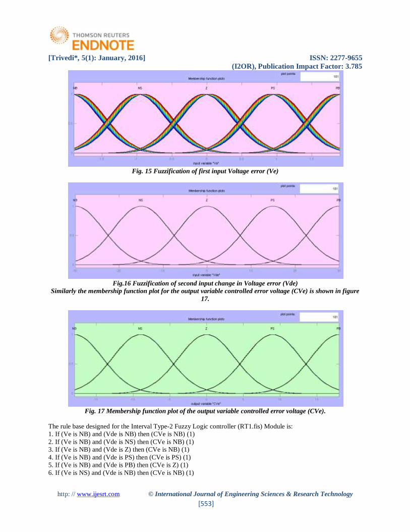
Now Fig.15 and Fig.16 shows membership functions of developed Interval Type-2 Fuzzy Logic controller (RT1.fis).
[Trivedi*, 5(1): January, 2016] ISSN: 2277-9655
(I2OR), Publication Impact Factor: 3.785
http: // www.ijesrt.com © International Journal of Engineering Sciences & Research Technology
[553]
Fig. 15 Fuzzification of first input Voltage error (Ve)
Fig.16 Fuzzification of second input change in Voltage error (Vde)
Similarly the membership function plot for the output variable controlled error voltage (CVe) is shown in figure
17.
Fig. 17 Membership function plot of the output variable controlled error voltage (CVe).
The rule base designed for the Interval Type-2 Fuzzy Logic controller (RT1.fis) Module is:
1. If (Ve is NB) and (Vde is NB) then (CVe is NB) (1)
2. If (Ve is NB) and (Vde is NS) then (CVe is NB) (1)
3. If (Ve is NB) and (Vde is Z) then (CVe is NB) (1)
4. If (Ve is NB) and (Vde is PS) then (CVe is PS) (1)
5. If (Ve is NB) and (Vde is PB) then (CVe is Z) (1)
6. If (Ve is NS) and (Vde is NB) then (CVe is NB) (1)

[Trivedi*, 5(1): January, 2016] ISSN: 2277-9655
(I2OR), Publication Impact Factor: 3.785
http: // www.ijesrt.com © International Journal of Engineering Sciences & Research Technology
[554]
7. If (Ve is NS) and (Vde is NS) then (CVe is NB) (1)
8. If (Ve is NS) and (Vde is Z) then (CVe is NS) (1)
9. If (Ve is NS) and (Vde is PS) then (CVe is Z) (1)
10. If (Ve is NS) and (Vde is PB) then (CVe is PS) (1)
11. If (Ve is Z) and (Vde is NB) then (CVe is NB) (1)
12. If (Ve is Z) and (Vde is NS) then (CVe is NS) (1)
13. If (Ve is Z) and (Vde is Z) then (CVe is Z) (1)
14. If (Ve is Z) and (Vde is PS) then (CVe is PS) (1)
15. If (Ve is Z) and (Vde is PB) then (CVe is PB) (1)
16. If (Ve is PS) and (Vde is NB) then (CVe is NS) (1)
17. If (Ve is PS) and (Vde is NS) then (CVe is Z) (1)
18. If (Ve is PS) and (Vde is Z) then (CVe is PS) (1)
19. If (Ve is PS) and (Vde is PS) then (CVe is PB) (1)
20. If (Ve is PS) and (Vde is PB) then (CVe is PB) (1)
21. If (Ve is PB) and (Vde is NB) then (CVe is Z) (1)
22. If (Ve is PB) and (Vde is NS) then (CVe is PS) (1)
23. If (Ve is PB) and (Vde is Z) then (CVe is PB) (1)
24. If (Ve is PB) and (Vde is PS) then (CVe is PB) (1)
25. If (Ve is PB) and (Vde is PB) then (CVe is PB) (1)
Similar to previous proposed controller Interval Type-2 Fuzzy Logic controller VST2.fis, during designing of rule
base and membership functions for second proposed Type-2 Fuzzy Logic controller VST1.fis short terms stands as:NB
= Negative Big, NS = Negative Small, Z = Zero Error, PS = Positive Small and PB = Positive Big.
Finally the layout of the second developed Interval Type-2 Fuzzy Logic controller (RT1.fis), for efficient regulation
of the terminal voltage Vt is shown in fig.18.
Fig. 18 The layout of the developed Interval Type-2 Fuzzy Logic controller (RT1.fis)
[Trivedi*, 5(1): January, 2016] ISSN: 2277-9655
(I2OR), Publication Impact Factor: 3.785
http: // www.ijesrt.com © International Journal of Engineering Sciences & Research Technology
[555]
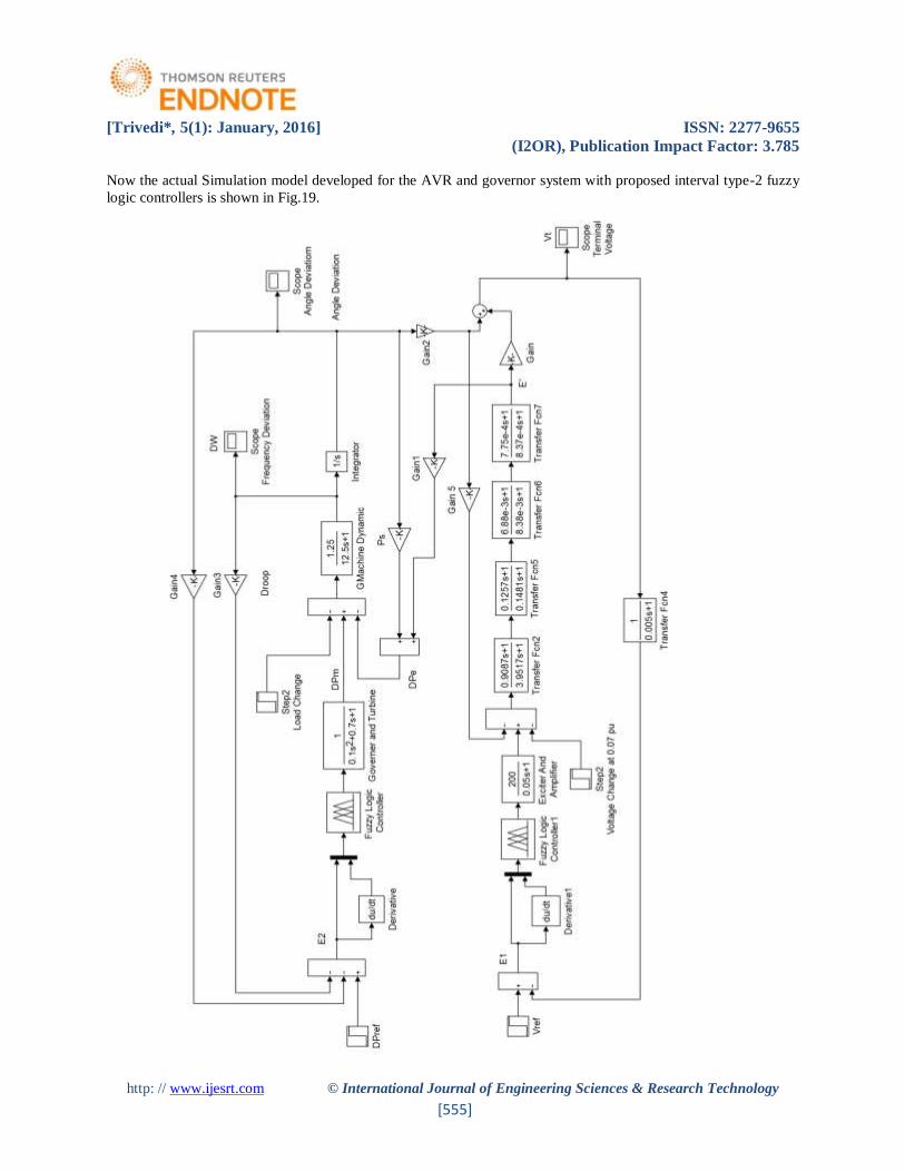
Now the actual Simulation model developed for the AVR and governor system with proposed interval type-2 fuzzy
logic controllers is shown in Fig.19.
[Trivedi*, 5(1): January, 2016] ISSN: 2277-9655
(I2OR), Publication Impact Factor: 3.785
http: // www.ijesrt.com © International Journal of Engineering Sciences & Research Technology
[556]
Fig.19 Actual Simulation model developed for the AVR and governor system with proposed interval type-2 fuzzy
logic controllers
The generator and system parameters used here also same as given in Table 1.
Simulation Results
This section is focusing on the simulation results of the SG model under transient response with various load change.
MATLAB program simulation method is adopted to simulate different cases related to terminal voltage and frequency
responses of a fourth order model of SG. The model is inserted in the Simulink diagram and run firstly for the case
without controller to calculate values of overshooting and settling time from the output response. To improve this
response then a PID controller is introduced and then the proposed Interval type-2 fuzzy logic controller (IT2FLC) is
examined.
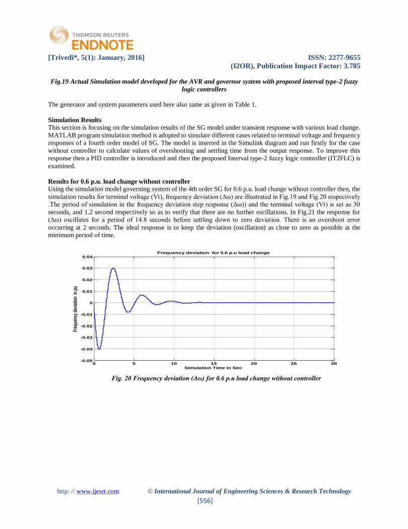
Results for 0.6 p.u. load change without controller
Using the simulation model governing system of the 4th order SG for 0.6 p.u. load change without controller then, the
simulation results for terminal voltage (Vt), frequency deviation (Δω) are illustrated in Fig.19 and Fig.20 respectively
.The period of simulation in the frequency deviation step response (Δω)) and the terminal voltage (Vt) is set as 30
seconds, and 1.2 second respectively so as to verify that there are no further oscillations. In Fig.21 the response for
(Δω) oscillates for a period of 14.8 seconds before settling down to zero deviation. There is an overshoot error
occurring at 2 seconds. The ideal response is to keep the deviation (oscillation) as close to zero as possible at the
minimum period of time.
Fig. 20 Frequency deviation (Δω) for 0.6 p.u load change without controller
0 5 10 15 20 25 30-0.05
-0.04
-0.03
-0.02
-0.01
0
0.01
0.02
0.03
0.04
Simulation Time in Sec
Freq
uenc
y de
viat
ion
in p
u
Frequency deviation for 0.6 p.u load change
[Trivedi*, 5(1): January, 2016] ISSN: 2277-9655
(I2OR), Publication Impact Factor: 3.785
http: // www.ijesrt.com © International Journal of Engineering Sciences & Research Technology
[557]
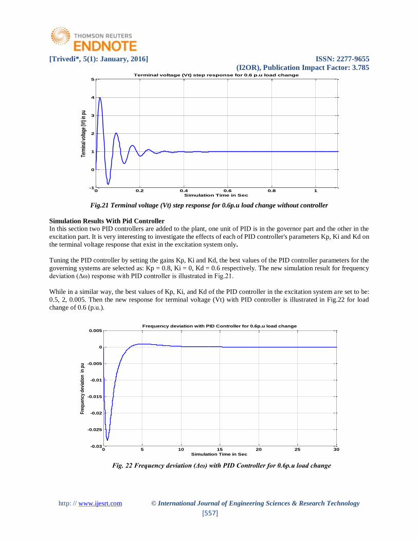
Fig.21 Terminal voltage (Vt) step response for 0.6p.u load change without controller
Simulation Results With Pid Controller
In this section two PID controllers are added to the plant, one unit of PID is in the governor part and the other in the
excitation part. It is very interesting to investigate the effects of each of PID controller's parameters Kp, Ki and Kd on
the terminal voltage response that exist in the excitation system only.
Tuning the PID controller by setting the gains Kp, Ki and Kd, the best values of the PID controller parameters for the
governing systems are selected as: Kp = 0.8, Ki = 0, Kd = 0.6 respectively. The new simulation result for frequency
deviation (Δω) response with PID controller is illustrated in Fig.21.
While in a similar way, the best values of Kp, Ki, and Kd of the PID controller in the excitation system are set to be:
0.5, 2, 0.005. Then the new response for terminal voltage (Vt) with PID controller is illustrated in Fig.22 for load
change of 0.6 (p.u.).
Fig. 22 Frequency deviation (Δω) with PID Controller for 0.6p.u load change
0 0.2 0.4 0.6 0.8 1-1
0
1
2
3
4
5Terminal voltage (Vt) step response for 0.6 p.u load change
Term
inal
vol
tage
(Vt)
in p
u
Simulation Time in Sec
0 5 10 15 20 25 30-0.03
-0.025
-0.02
-0.015
-0.01
-0.005
0
0.005
Simulation Time in Sec
Fre
qu
ency
dev
iatio
n i
n p
u
Frequency deviation with PID Controller for 0.6p.u load change

[Trivedi*, 5(1): January, 2016] ISSN: 2277-9655
(I2OR), Publication Impact Factor: 3.785
http: // www.ijesrt.com © International Journal of Engineering Sciences & Research Technology
[558]
Fig. 23 Terminal voltage (Vt) step response with PID controller for 0.6 p.u load change
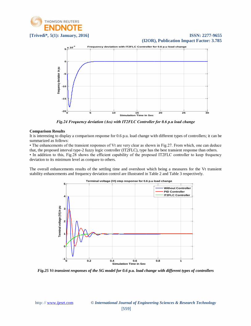
Simulation results with IT2FLC
In this case, the IT2FLC controller for prediction and control the SG to enhance terminal voltage response in the
excitation system is examined. The controlling steps and output response is discussed in the following section. Return
to the Simulink model and start the simulation by choosing the start command from the Simulation menu. As the
simulation runs, the plant output and the reference signal are displayed. Fig.24 shows the terminal voltage response
for the 4th order SG model using proposed IT2FLC controller RT1.fis. The frequency deviation control response with
proposed IT2FLC controller RT2.fis is shown in fig.25 for load change of 0.6 pu.
Fig.23 Terminal voltage step response with IT2FLC controller for 0.6 p.u load change
0 0.2 0.4 0.6 0.8 1-1
-0.5
0
0.5
1
1.5
2
2.5
3
3.5
4Terminal voltage (Vt) step response with PID controller for 0.6 p.u load change
Term
inal
vol
tage
(Vt)
in p
u
Simulation Time in Sec
0 0.2 0.4 0.6 0.8 10
0.5
1
1.5Terminal voltage (Vt) step response with IT2FLC controller for 0.6 p.u load change
Term
inal
vol
tage
(Vt)
in p
u
Simulation Time in Sec
[Trivedi*, 5(1): January, 2016] ISSN: 2277-9655
(I2OR), Publication Impact Factor: 3.785
http: // www.ijesrt.com © International Journal of Engineering Sciences & Research Technology
[559]
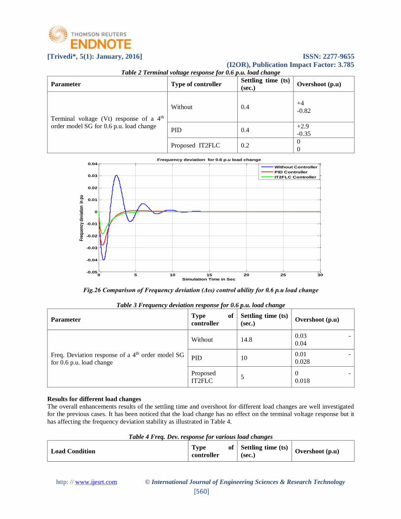
Fig.24 Frequency deviation (Δω) with IT2FLC Controller for 0.6 p.u load change
Comparison Results
It is interesting to display a comparison response for 0.6 p.u. load change with different types of controllers; it can be
summarized as follows:
• The enhancements of the transient responses of Vt are very clear as shown in Fig.27. From which, one can deduce
that, the proposed interval type-2 fuzzy logic controller (IT2FLC), type has the best transient response than others.
• In addition to this, Fig.28 shows the efficient capability of the proposed IT2FLC controller to keep frequency
deviation to its minimum level as compare to others.
The overall enhancements results of the settling time and overshoot which being a measures for the Vt transient
stability enhancements and frequency deviation control are illustrated in Table 2 and Table 3 respectively.
Fig.25 Vt transient responses of the SG model for 0.6 p.u. load change with different types of controllers
0 5 10 15 20 25 30-20
-15
-10
-5
0
5x 10
-3
Simulation Time in Sec
Freq
uenc
y de
viat
ion
in p
u
Frequency deviation with IT2FLC Controller for 0.6 p.u load change
0 0.2 0.4 0.6 0.8 1-1
0
1
2
3
4
5Terminal voltage (Vt) step response for 0.6 p.u load change
Ter
min
al v
olta
ge
(Vt)
in p
u
Simulation Time in Sec
Without Controller
PID Controller
IT2FLC Controller
[Trivedi*, 5(1): January, 2016] ISSN: 2277-9655
(I2OR), Publication Impact Factor: 3.785
http: // www.ijesrt.com © International Journal of Engineering Sciences & Research Technology
[560]
Table 2 Terminal voltage response for 0.6 p.u. load change
Parameter Type of controller Settling time (ts)
(sec.) Overshoot (p.u)
Terminal voltage (Vt) response of a 4th
order model SG for 0.6 p.u. load change
Without 0.4 +4
-0.82
PID 0.4 +2.9
-0.35
Proposed IT2FLC 0.2 0
0
Fig.26 Comparison of Frequency deviation (Δω) control ability for 0.6 p.u load change
Table 3 Frequency deviation response for 0.6 p.u. load change
Parameter Type of
controller
Settling time (ts)
(sec.) Overshoot (p.u)
Freq. Deviation response of a 4th order model SG
for 0.6 p.u. load change
Without 14.8 0.03 -
0.04
PID 10 0.01 -
0.028
Proposed
IT2FLC 5
0 -
0.018
Results for different load changes
The overall enhancements results of the settling time and overshoot for different load changes are well investigated
for the previous cases. It has been noticed that the load change has no effect on the terminal voltage response but it
has affecting the frequency deviation stability as illustrated in Table 4.
Table 4 Freq. Dev. response for various load changes
Load Condition Type of
controller
Settling time (ts)
(sec.) Overshoot (p.u)
0 5 10 15 20 25 30-0.05
-0.04
-0.03
-0.02
-0.01
0
0.01
0.02
0.03
0.04
Simulation Time in Sec
Freq
uenc
y de
viat
ion
in p
u
Frequency deviation for 0.6 p.u load change
Without Controller
PID Controller
IT2FLC Controller
[Trivedi*, 5(1): January, 2016] ISSN: 2277-9655
(I2OR), Publication Impact Factor: 3.785
http: // www.ijesrt.com © International Journal of Engineering Sciences & Research Technology
[561]
Freq. Deviation response of a 4th order model SG
for 0.6 p.u. load change
Without 14.8 0.03 -
0.04
PID 10 0 -
0.028
Proposed
IT2FLC 5
0 -
0.018
Freq. Deviation response of a 4th order model SG
for 0.3 p.u. load change
Without 14.7 0.035 -
0.024
PID 11 0.08 -
0.017
Proposed
IT2FLC 5
0 -
0.007
CONCLUSIONS This work has put forward a new scenario in the steam turbine control structure, by development of Interval Type-2
Fuzzy based Control Model of steam turbine Governing System and excitation system of Power Plant, which
compensates their control, inputs during faults. Two separate Interval Type-2 Fuzzy controllers have been developed
to address both the damping of frequency deviation and terminal voltage oscillation problems. To present complete
comparative analysis of the proposed control strategy with conventional PID controller, two separate fluctuations
scenario have been employed. SIMULINK simulation model is built to study the dynamic behaviour of conventional
PID controlled synchronous machine and the performance of proposed IT2FLC controller.
The main conclusions of this work can be summarized as follows:
1. Building of fourth order simulation model for SG, speed governor and exciter voltage regulator for SMIB
system under study enables to treat the problem (transient state power system stability) with much ease and
comfort.
2. Due to the weak coupling relationship between the AVR and AGC of the synchronous generator controls
systems, the voltage and frequency controls are regulated separately that mean any controller in the excitation
system will not affect governing system and vice versa.
3. The conventional PID controller used, suffers from the high settling time and overshoot values, for the
transient responses of both the obtained terminal voltage and frequency deviation.
4. The proposed IT2FLC Controller gives excellent results. It shows the high efficiency in controlling the
overshoot and undershoots in the transient part, as well as keeps efficient control on the output during steady
state part. Moreover the terminal voltage transient stability response enhancements through the obtained
results are outstanding with respect to the conventional PID controller. By this controller, the generator
terminal voltage profile and the generator transient stability response are improved.
REFERENCE [1] Jerry M.Mendel, Feilong Liu, “Super-Exponential Convergence of the Karnik–Mendel Algorithms for
Computing the Centroid of an Interval Type-2 Fuzzy Set”, IEEE, April 2007.
[2] Imam Robandi, and Bedy Kharisma” Design of Interval Type-2 Fuzzy Logic Based Power System Stabilizer”
Proc. of world Academy of Science, Engineering and Technology Vol 31., ISSN 1307-6884,2008.
[3] Chakraborty D and Pal N.R. “ Neuro-fuzzy scheme for simultaneous feature Selection and Fuzzy Rule-based
Classification “ IEEE Transactions on NN, Vol 15, No1, PP 110-123, 2004
[4] Chakrabarty D and Pal N.R. “Integrated feature analysis and fuzzy Rule-based system identification in a
Neuro-fuzzy Paradigm” IEEE Translations on syst. Man, and cybernetics, Vol 31, No3, PP 391-400, 2001.
[5] Imam Robandi, “Modern Power System Design” (Desain System Tenaga Modern, in Bahasa Indonesia),
Andi Offset Publisher: 2006

[Trivedi*, 5(1): January, 2016] ISSN: 2277-9655
(I2OR), Publication Impact Factor: 3.785
http: // www.ijesrt.com © International Journal of Engineering Sciences & Research Technology
[562]
[6] Masoud S.H. etal “ Simulation and performance analysis of the new geothermal co-generation power plant
at Svartsengi” Proc. Of world geo congress, Japan, PP3315-3320, 2000.
[7] M. Dobrescu, I. Kamwa, “A New Fuzzy Logic Power System Stabilizer Performances”, IEEE, 2004.
[8] P. Kundur, “Power System Stability and Control”, McGraw-Hill,1993.
[9] Sood V.K. and Ramchandran V. “Modeling a fuzzy logic controller for power converters in EMTPRV” Inter
conf. On PS (IPST 05), Canada, PP 1-5, 2005.
[10] Jong Wook Kim and Sang Woo Kim “Design of incremental fuzzy PI controllers for a gas-turbine plant”
IEEE / ASME Trans. On Mechatronics, Vol 8 No3, PP 410-414, 2003.
[11] Juan R. Castro, Oscar Castillo, “Interval Type-2 Fuzzy Logic for Intelligent Control Applications”, IEEE,
2007.
[12] Bao-Gang Hu etal “A systematic study of fuzzy PID controllers function –based evaluation approach” IEEE
Trans on fuzzy systems, Vol. 9, 2001.
[13] Timothy J. Ross, “Fuzzy Logic with engineering Applications”, McGraw-Hill, 1997.
[14] Sudath R.M., Min-Soeng Kim and Lee J.J. “ Adaptive Neuro fuzzy controller to Regulate UTSG Water Level
in Nuclear Power Plants” IEEE Transactions on Nuclear science, Vol 52, No1, PP 421-429, 2005.
[15] Jerry M. Mendel, Robert I. Bob John, “Type-2 Fuzzy Sets Made Simple”, IEEE, April, 2002.
[16] Na M.G. “Design of an adaptive predictive controller for steam generators” IEEE Trans. Nucl. Sci. Vol. 50,
No.1, PP 186-193, 2003.
[17] Dash P.K., Mishra S and Panda G. “Damping Multimodal Power System Oscillation using a Hybrid fuzzy
Controller for series connected facts devices” IEEE Trans. On power systems, Vol 15, No. 4, 2000.
[18] Qilian Liangand, Jerry M. Mendel, “Interval Type-2 Fuzzy Logic System Theory and Design”, IEEE,
October, 2000.
[19] Mitra S. and Hayashi Y, “Neuro-fuzzy rule generation survey in soft computing framwork” IEEE
Transactions on Neural Networks, Vol II, No3, PP 748-768, 2000.


![Interval Notation: ], not interval notationpgrant.weebly.com/uploads/2/3/2/7/23274454/6.3b_interval_notation.… · •Interval Notation: Uses different brackets to indicate an interval](https://img.dokumen.tips/doc/110x75/5f8344624904df613146ef90/interval-notation-not-interval-ainterval-notation-uses-different-brackets.jpg)