Embed Size (px)
Citation preview

Isokern® MAGNUM® Fireplaceand DM Chimney System
Installation, Operation, Maintenance and Owner’s ManualIsokern MAGNUM Models 82060 & 82072A PRODUCT OF EARTHCORE® INDUSTRIES, LLC
Important: This manual contains assembly rules, installation steps, guidelines, use and maintenance instructions for the MAGNUM 82060 & 82072 Series fireplace and the DM chimney system. This manual must become the property of and be reviewed by all current and future users of this product. It is the responsibility of the general contractor and the installer of this product to ensure that the instructions in this manual are followed exactly and, further that any allowed gas log appliance used in this product be installed in strict accordance with NFPA 58, NFPA 54/ANSI Z223.1 and the gas log manufacturer’s explicit installation, sizing and operation instructions. It is the responsibility of the general contractor to provide adequate clearances from all firebox surfaces as specified in this manual.
INSTALLER: Leave this manual with the fireplaceCONSUMER: Retain this manual for future reference
Be Sure to Read Entire Manual Before Beginning Construction.Contents of this manual may change without prior notification.
WARNING:FIRE OR EXPLOSION HAZARDFailure to follow safety warning exactly could result in serious injury, death, or property damage.
— Do not store or use gasoline or other flammable vapors and liquids in the vicinity of this or any other appliance.
— WHAT TO DO IF YOU SMELL GAS • Do not try to light any appliance. • Leave the building immediately. • Do not touch any electrical switch; do not use any phone in your building. • Immediately call your gas supplier from a neighbor’s phone. Follow the gas supplier’s instructions. • If you cannot reach your gas supplier, call the fire department.
— Installation and service must be performed by a qualified installer, service agency or the gas supplier.
Issued: August 2016Revision: 002
©2016 Earthcore Industries, LLCListing Services Report NO. 3082504-T1
THESE FIREPLACES ARE DESIGNED for USE with:Solid Wood Logs, PROPANE (LP) or NATURAL GAS (NG), ONLY
THIS MANUAL CAN ONLY BE REPRODUCED IN ITS ENTIRETY
DO NOT install the MAGNUM Series Fireplace in a manufactured home or mobile home or recreational vehicle.
SBCCI NO. 9626NYC-MEA 241-90-E
ICC Report NO. ESR-2316LA RR NO. 25483
IBC 2006, IRC 2006, IMC 2006

General Information ................................................. 3 - 4
Safety Instructions ................................................... 5 - 6
Warnock-Hersey Listing Label ...................................... 7
MAGNUM Series 60" - Firebox Dimensions ................ 8
Component List - MAGNUM Series 60" ....................... 9
MAGNUM Series 72" - Firebox Dimensions ...............10
Component List - MAGNUM Series 72" ......................11
Required Clearance to Combustibles ...................12 - 13
Supporting Floor System .............................................14
Rough Framing Dimensions ........................................15
General Assembly Instructions ....................................16
Assembly Instrucitons - MAGNUM Serier 60" ......17 - 21
Assembly Instrucitons - MAGNUM Serier 72" ..... 22 - 26
DM Chimney Components & General Information..... 27
DM Chimney Height Requirements ........................... 28
DM Chimney Installation - Straight Run .............. 29 - 30
DM Chimney Installation - Offset Run ................. 31 - 33
DM Brick Ledge ................................................... 34 - 36
DM Chimney Terminations ......................................... 37
Metal Chimney Flue ................................................... 38
Component List - ECO-STEEL Metal Chimney ........... 39
2
Earthcore IndustriesMAGNUM Fireplace - 60 & 72 09/2016
Table of Contents
ECO-STEEL General Information ................................ 40
ECO-STEEL Metal Chimney Installation .............. 41 - 45
Access Modification:
Combustion Air Kits, Gas & Electrical Line Feed ........ 46
Firebrick Installation ............................................. 47 - 48
Clearance to Combustilble Trim .................................. 49
Outdoor Application .................................................... 50
Summary ............................................................. 51 - 53
Registration Card ........................................................ 55
Warranty ..................................................................... 56

3
The MAGNUM Series fireplace and DM chimney system is a prefabricated, refractory modular fireplace and chimney system designed for field assembly. The system consists of interlocking precast parts which are glued together with a masonry adhesive. The parts of the MAGNUM Series fireplace and DM chimney system are precast using a proprietary mixture of volcanic pumice aggregate and cement. It includes all the parts necessary for assembly of a complete firebox, smoke dome and chimney system. Each MAGNUM precast fireplace component is designed for a specific part of the fireplace such that only one means for assembly is possible. The firebox and smoke dome are designed to be fitted with a traditional cast iron, poker-style throat damper. However, in-line or chimney top dampers are options. The MAGNUM Series fireplace requires a standard refractory firebrick liner be applied to the interior of the firebox. Firebrick must be a minimum thickness of one and one-eighth inch (1-1/8”) on the floor and back walls. A minimum four inch (4”) firebrick must be applied to the side walls. The MAGNUM Series fireplace is available in two sizes: sixty inch (60”) and seventy-two inch (72”). All units have a thirty-eight inch (38”) rough opening height before firebrick. The only parts which differ among the available sizes are width related pieces. All units use the same side wall pieces. The DM chimney system is a dual module refractory chimney system. The basic chimney consists of an outer casing block and an inner liner. Two (2) flues are necessary on the 82060 & 82072 models without a mechanical drafting system. It is acceptable to use mechanical draft systems, if the venting companies do the engineering calculations and make the necessary recommendations for fan size and flue vent diameter following the guidelines of NFPA 211/2006, pg. 211-13. Installation of such systems must also follow the mechanical drafting company’s explicit installation and operation instructions. “Smoke free” operation is not warranted nor is the manufacturer responsible for inadequate system draft caused by mechanical systems, general construction conditions, inadequate chimney heights, adverse wind conditions or any unusual environmental conditions or factors beyond the manufacturer’s control. The DM chimney components are field assembled using Earthcore Mortar to glue the components together. The DM chimney system also includes an offset chimney block component, used to create offsets to the vertical run of the chimney. A brick ledge component is available, designed to support chimney top brick veneer finishes. Prefabricated masonry chimney termination caps are also available. The MAGNUM Series fireplace and DM chimney components will be described and illustrated in the
Earthcore Industries09/2016 MAGNUM Fireplace - 60 & 72
General Information
following pages. Close attention should be paid to each component group’s specifications and installation requirements as described in this manual. Maximum overall height for the MAGNUM Series and DM chimney system for an indoor application is 22’-0” without additional structural support. This restriction does not apply for metal chimney systems.
Intended Product Use Statement: The MAGNUM Series fireplace and DM chimney systems are intended to burn solid wood fuel, propane or natural gas.
NOTE: Installation of a gas pipe must comply with the Standard for Decorative Gas Appliances for Installation in Vented Fireplaces, ANSI Z21.60.
This fireplace is intended for use as a supplemental heat source only and is not intended for heavy use as a primary heating system. Over-firing, abusive burning or mistreatment will void any claims (eg. burning construction debris or other highly flammable material; tossing, kicking or otherwise forcing logs into the firebox). The MAGNUM Series fireplaces and DM chimney systems are conventional indoor or outdoor fireplaces designed to appear like traditional masonry fireplaces. The MAGNUM Series fireplace and DM chimney system units are intended for installation in residential homes and other buildings of conventional construction.
NOTE: The local authority having code jurisdiction should be consulted before installation to determine the need to obtain a permit.
Important areas of concern with the installation of these fireplaces are: construction of proper load bearing foundation and concrete support slab; code required hearth extension substrates and supports; proper assembly of components; clearance to combustible materials; height of chimney; and techniques employed in applying finishing materials to the fireplace opening and hearth extension. Each of these important topics will be covered in detail throughout this manual. Installation personnel must give special attention to each topic as the installation progresses. All work performed on, near and adjoining the fireplace and chimney installation must meet or exceed the specifications and requirements in this manual and the prevailing local building code. Subsequent renovations, additions of cabinets and storage spaces in the enclosure surrounding the fireplace are also limited to the specifications in this manual and to the prevailing local building code.

4
Earthcore IndustriesMAGNUM Fireplace - 60 & 72 09/2016
General Information
Isokern is not responsible for other construction work around the fireplace unit. Glass Doors: See page 52 for approved list of glass door manufacturers for use on all Isokern Fireplaces. We require two (2) outside air kits be installed into the fireplace with a minimum duct size of 4” to provide an adequate make up air supply. All glass must be a minimum of 3/16” in thickness and shall be of tempered or ceramic glass as supplied by our approved vendors. DOORS MUST BE KEPT IN THE OPEN POSITION WHEN FIREPLACE IS IN USE. The MAGNUM Series fireplace and DM chimney system is tested and listed by Warnock Hersey (Intertek Testing Service) - Report No. 3082504-T1 - to UL 127, and UL 103HT. MAGNUM Series fireplace systems are also designed for installation in accordance with the National Fire Protection Association Standard for chimneys, fireplaces, vents and Solid Fuel-Burning Appliances (NFPA 211). If you are installing the MAGNUM Series Fireplace in a location where there is seismic code follow these instructions for installation. Four No. 4 ASTM A615 Grade 40 minimum, vertical reinforcing bars, 2 on each side ofthe fire box running from mid-height (where the tapered section of the box begins) of the structure to approximately 4 inches into the concrete slab (for anchorage).
IMPORTANT: The top plate of the firebox is not meant to be used as a structural support. Please consult structural engineer for structural support of any veneer bearing weight on the Isokern top plate.
NOTE: Do not scale drawings. Illustrations in this manual are not to scale and are intended to show “typical” installations. Nominal dimensions are given for design and framing reference only, since actual installations may vary due to job specific design preferences. Always maintain the stated minimum clearances to combustible materials. Do not violate any specific installation requirements.
5
WARNING: This product contains or generates chemicals known to the state of California to cause cancer or birth defects or other reproductive harm.
IMPORTANT: Read this owner’s manual carefully and completely before trying to assemble, operate or service this fireplace. Improper use of this fireplace can cause serious injury or death from fire, burns, explosions and carbon monoxide poisoning.
DANGER: CARBON MONOXIDE POISONING MAY LEAD TO DEATH! If gas application is used with MAGNUM Series fireplace; Propane (LP) gas and natural gas (NG) are both colorless and odorless gases. An odor-making agent is added to each of these gases to help you detect a gas leak. However, the odor added to these gases can fade and gas may be present even though no odor exists. Carbon Monoxide Poisoning: Early signs of carbon monoxide poisoning resemble flu symptoms, including headaches, dizziness or nausea. If you have these signs the fireplace may not have been installed properly, get fresh air at once! Have the fireplace inspected and serviced by a qualified service person or your gas supplier. Some people are more affected by carbon monoxide than others. These include pregnant women, people with heart or lung diseases or anemia, people at high altitude or under the influence of alcohol. Earthcore Industries strongly recommends the use of a carbon monoxide detector/alarm device wherever gas fired appliances are in use. All parties either involved in or associated with the installation, service and use of this fireplace must read this entire manual. Keep this manual for reference and as a guide book to safe operation of this fireplace.
1. Always check local building codes governing fireplaces and fireplace installations. The MAGNUM Series fireplace and DM chimney installation must comply with all local, regional, state and national codes and regulations.
2. The MAGNUM Series fireplace and DM chimney systems are intended for use in any application where a traditional masonry type fireplace would apply. The chimney system must always vent vertically to the outside of the building.
3. Creosote and soot formation and the need for removal: When wood is burned slowly, it produces tar and other organic vapors which combine with expelled moisture to form creosote. The creosote vapors condense in the relatively cool chimney flue of a slow burning fire. As a result, creosote residue accumulates on the flue lining. When ignited this creosote makes an extremely hot fire.
Earthcore Industries09/2016 MAGNUM Fireplace - 60 & 72
Safety Instructions
Because of creosote and soot buildup it is necessary to inspect and clean the fireplace and chimney prior to use and periodically during the heating season. Cleaning of the fireplace and the chimney system should be done annually at a minimum. In colder climates, chimney cleaning may need to be done periodically throughout the heating season.
4. Before servicing, allow the fireplace to cool. Always shut off any electricity or gas to the fireplace while working on it.
5. Use only solid fuel or Natural Gas or LP Gas log sets in this unit. Do not use artificial wax based logs, chemical chimney cleaners or flame colorants in this fireplace.
6. For propane (LP) use do not place propane supply tank(s) inside any structure. Locate propane supply tank(s) outdoors. To prevent performance problems, do not use propane fuel tank of less than 100 lbs. capacity.
7. Never use gasoline, kerosene, gasoline-type lantern fuel, charcoal lighter fluid, or similar liquids to start or “freshen up” a fire in this fireplace. Keep all flammable liquids at a safe distance from the fireplace.
8. Always keep the flue damper open when heat is present in the fireplace.
9. Do not use a fireplace insert or any other product not specified for use with the MAGNUM Series fireplace and DM chimney systems unless written authorization is given by Earthcore Industries, LLC. Failure to heed this warning may cause a fire hazard and will void the warranty.
10. This fireplace is not intended to heat an entire home or to be used as a primary heat source. It is designed to ensure homeowner comfort by providing supplemental heat to the room.
11. Always ensure that an adequate supply of replacement combustion air from the outside of the house is accessible to the fire to support normal combustion. Fireplaces consume large volumes of air during the normal firing process. In the event the home is tightly sealed and has modern energy efficient features, the combustion air supply kits may not provide all the air required to support combustion and the proper flow of combustion gases up the chimney.

The manufacturer is not responsible for any smoking or related problems that may result from the lack of adequate air supply flowing into the house. It is the responsibility of the builder/contractor to ensure that adequate air supply has been provided for the fireplace.
CAUTION: When used with the MAGNUM Series fireplace system, all gas log sets must be operated with the damper clamped in the fully open position. This includes unlisted “vent free” log sets. Only listed “vent free” log sets may be operated with the damper in the closed position.
12. When in doubt about a component’s usability - has visible or suspected physical damage - consult your Isokern distributor or authorized Isokern representative for advice.
13. Modification to MAGNUM components not mentioned in this manual may void claims, listings and approvals and could result in an unsafe and potentially dangerous installation. Alterations to the MAGNUM firebox are allowed with prior written approval and instructions from Earthcore Industries, LLC. The installer indemnifies the manufacturer of all claims and under no circumstances will the manufacturer be liable for consequential, incidental, indirect, punitive or other damages of any kind or nature, whether foreseeable or not, based on any claim by any party as to the modifications of the Isokern fireplaces.
14. Keep all insulation, vapor barriers, “house wrap” paper and other insulating type membranes and products, including fiberglass, cellulose and other insulation, (anything that carries an “R” rating) a minimum of three inches (3”) away from all firebox and chimney surfaces.
EXCEPTION: If insulation is used in walls surrounding the fireplace, insulation may be installed behind sheathing of gypsum board, plywood, particle board or other material on the side facing the Isokern. The facing material cannot be within 1 1/2” to the fireplace sidewalls.
WARNING: Do not pack required air spaces with insulation or other materials.
15. Never leave children unattended when there is a fire burning in the fireplace.
16. Burning some fuels (such as charcoal) can be hazardous due to the possibility of producing carbon monoxide, a colorless, odorless gas. Early signs of carbon monoxide poisoning resemble flu symptoms, including headaches, dizziness or nausea. Over exposure to carbon monoxide
6
Earthcore IndustriesMAGNUM Fireplace - 60 & 72 09/2016
Safety Instructions
can lead to illness and death. It is strongly recommended to install smoke and carbon monoxide alarm / detector devices wherever fireplaces are installed.
17. Young children should be carefully supervised when they are in the same room as the appliance. Toddlers, young children and others may be susceptible to accidental contact burns. A physical barrier is recommended if there are at-risk individuals in the house. To restrict access to the fireplace, install a adjustable safety gate to keep toddlers, young children and other at-risk individuals out of the room and away from hot surfaces.
18. Clothing or flammable material should not be placed on or near the fireplace.
19. Due to high temperatures, the fireplace should be located out of traffic and away from furniture and draperies.
20. If glass doors are installed with the fireplace Do NOT clean glass front when hot or in use. Wait until Fireplace is OFF and has cooled to room temperature before cleaning glass. Do not use abrasive cleaners on the glass.

7
Earthcore Industries09/2016 MAGNUM Fireplace - 60 & 72
Warnock Hersey Listing Label
Isokern Fireplace and Chimney Systems are tested and listed to UL standards: UL 127, ULC S610, and UL 103HT. The listing label shown in Figure 1 above outlines the listed clearances to combustibles and indicates that the units are suitable for use with solid fuel or listed gas appliances. Refer to the manufacturer’s installation manual for detailed description of clearances to combustibles and all other installation information.
A metal listing label similar to those shown above is affixed to each fireplace. Do not remove the listing label from the fireplace.
Prior to beginning installation, contact your local building official to determine the need to obtain a permit.

8
Earthcore IndustriesMAGNUM Fireplace - 60 & 72 09/2016
MAGNUM Series 60” (82060)
85 ¾”
38”
53 ½”
9 ½”
57 ¼”
69”
73 ½”
2 ¾”
38”
25 ¼”
85 ¾”
44 ¾”
41”
5”
32”
8”
60” Damper
28”
69”
73 ½”
57 ¼”
Front View Side View
Plan View Top View
10 ¾”
25 ¼”
26 ¾” 26 ¾”
14”Flue Outlet
Uses two Isokern DM 54 Chimneys or ECO-STEEL Metal Chimney Pipe. Refer to page 39 manual for approved other Metal Chimney manufacturers.
NOTE: Steel angle: 4” x 6” x 5/16” cut to 731/2 to span firebox opening. This item is not included in the components and can be sourced locally.
NOTE: These are inside rough dimensions before firebrick

9
Earthcore Industries09/2016 MAGNUM Fireplace - 60 & 72
Component List - MAGNUM Series 60” (82060)
Component Part# Description
28”
43”
M91 Isokern MAGNUM Base Plate
28”
30½”
96 Isokern MAGNUM Base Plate
23¾”
15 Isokern MAGNUM Smoke Dome (Qty. 4)
4”
49¾”
16 Isokern MAGNUM Smoke Dome (Qty. 2)
4”
16”
39¾”
17 Isokern MAGNUM Smoke Dome (Qty. 2)
4”
16”
3”
25¼”
16” 34 Isokern MAGNUM Side Sloping (Qty. 4)
28”8”
9½”
2¼”
M90 Isokern MAGNUM Sidewall (Qty. 8)
22¼”
9½”
71 Isokern MAGNUM Backwall (Qty. 4)
Component Part# Description
72 Isokern MAGNUM Backwall (Qty. 4)
79L Isokern MAGNUM Top Plate - Left
79R Isokern MAGNUM Top Plate - Right
M94L & M94R Isokern MAGNUM Damper End Left & Right
74 Isokern MAGNUM Damper Beam (Qty. 2)
75 Isokern MAGNUM Damper Beam (Qty. 2)
38½”
9½”
25¼”
4¾”26¾”
25¼”
26¾”4¾”
35½"
8”
7 7/8”
8”
38"
7 7/8”
NOTE: Steel angle iron with measurements of 4” x 6” x 5/16” cut to 731/2” long to span firebox opening will be needed to assemble the firebox. This item is not included in the components and can be sourced locally.

10
Earthcore IndustriesMAGNUM Fireplace - 60 & 72 09/2016
MAGNUM Series 72” (82072)
85 ¾”
38”
66”
9 ½”
69 ¾”
81 ¼”
85 ½”
2 ¾”
38”
25 ¼”
85 ¾”
44 ¾”
41”
5”
32”
8”
72” Damper
28”
81 ¼”
85 ½”
69 ¾”
Front View Side View
Plan View Top View
33” 33”
10 ¾”
25 ¼”
14”Flue Outlet
Uses two Isokern DM 54 Chimneys or ECO-STEEL Metal Chimney Pipe. Refer to page 39 manual for approved other Metal Chimney manufacturers.
NOTE: Steel angle: 4” x 6” x 5/16” cut to 851/2 to span firebox opening. This item is not included in the components and can be sourced locally.
NOTE: These are inside rough dimensions before firebrick

11
Earthcore Industries09/2016 MAGNUM Fireplace - 60 & 72
Component List - MAGNUM Series 72” (82072)
Component Part# Description
28”
43”
M91 Isokern MAGNUM Base Plate (Qty. 2)
26"
19 Isokern MAGNUM Smoke Dome (Qty. 2)
4”
49¾”
16 Isokern MAGNUM Smoke Dome (Qty. 4)
4”
16”
36"
18 Isokern MAGNUM Smoke Dome (Qty. 2)
4”
16”
3”
25¼”
16” 34 Isokern MAGNUM Side Sloping (Qty. 4)
28”8”
9½”
2¼”
M90 Isokern MAGNUM Sidewall (Qty. 8)
9½”
73 Isokern MAGNUM Backwall (Qty. 4)
Component Part# Description
72 Isokern MAGNUM Backwall (Qty. 4)
M77 Isokern MAGNUM Top Plate (Qty. 2)
M94L & M94R Isokern MAGNUM Damper End Left & Right
83 Isokern MAGNUM Damper Beam (Qty. 2)
84 Isokern MAGNUM Damper Beam (Qty. 2)
38½”
9½”
25¼”
33”4¾”
39"
8”
7 7/8”
8”
46½"
7 7/8”
NOTE: Steel angle iron with measurements of 4” x 6” x 5/16” cut to 851/2” long to span firebox opening will be needed to assemble the firebox. This item is not included in the components and can be sourced locally.
34½”
12
Earthcore IndustriesMAGNUM Fireplace - 60 & 72 09/2016
Required Clearance to Combustibles
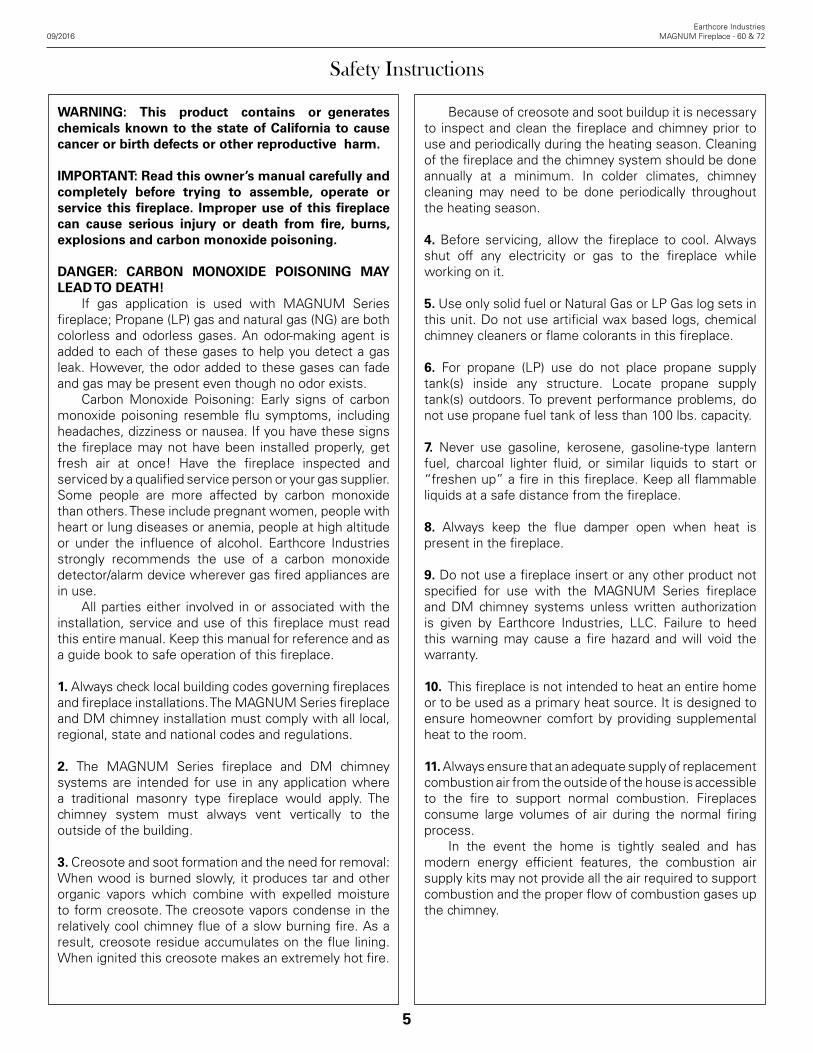
The MAGNUM Series fireplace and the DM chimney system is tested and listed for installation with “clearance to combustibles” as follows: All DM 54 chimney components require 0” clearance. (Figure 2) The MAGNUM Series firebox side walls and back wall require 1-1/2” clearance. (Figure 3) The smoke dome front wall requires 0” clearance.
NOTE: “Combustibles” are defined as “normal construction materials” and are considered to be: wood framing materials, particle board, mill board, plywood sub-flooring, plywood paneling and wood flooring. MAGNUM Series fireplaces are tested and listed for one and one-half inch (1-1/2”) clearance to combustible framing material at the firebox sides and back. Installation and use practices that are beyond the control of the manufacturer* can result in situations where clearance requirements (as determined through testing and as stated by the manufacturer) are not maintained due to construction subsequent to the installation of the Isokern unit. It is the general contractor’s responsibility to assure that listed clearances to combustible framing and to insulation are maintained throughout the construction of the project subsequent to the installation of the Isokern unit. To avoid causing a fire resulting in damage to property, personal injury or loss of life, do not pack or fill the required air spaces with insulation or other material. No material is allowed in these areas. (Figures 3 & 4) Keep all insulation, vapor barriers, “house wrap” paper and other insulating type membranes and products, including fiberglass, cellulose and other insulation, (anything that carries an “R” rating) a minimum of three inches (3”) away from all firebox and chimney surfaces.
IMPORTANT: The manufacturer is not responsible for installation and use practices that are beyond the scope of the product as defined in the product listing and in this installation manual.
Sheathing materials, such as plywood, particle board and drywall may cover the smoke dome front at 0” clearance. All combustible sheathing materials that protrude beyond front of firebox must be held 9” away from the sides of the firebox opening and 24” above the top of the firebox opening. Drywall must be cut 9” back from the firebox opening sides and 24” above the top of the opening. (Figure 3) EXCEPTION: If insulation is used in walls surrounding the fireplace, insulation may be installed behind sheathing of
FIGURE 2
FIGURE 3
0" Clearance
0" Clearance
COMBUSTIBLEFRAMING
9”MIN
1 ½”Min.
1 ½”Min.
1 ½”Min.

13
gypsum board, plywood, particle board or other material on the side facing the Isokern. The facing material cannot be within 1 1/2” to the fireplace sidewalls.
The MAGNUM Series fireplace must sit upon a concrete support slab designed to bear the total installed weight of the fireplace and DM chimney system. These support slabs can have no wood underpinnings. (Figure 5) See page 14 for more information on weight loads. Concrete support slabs for MAGNUM Series fireplaces must provide the non-combustible hearth extension substrate needed to support the code required non-combustible hearth extension finish materials. (Figures 2 and 3) All MAGNUM Series fireplaces shall have hearth extensions of approved non-combustible material such as brick, tile, or stone that is properly supported and with no combustible material against the underside thereof. Wooden forms used during the construction of hearths and hearth extensions must be removed when the construction is complete. If a raised fireplace floor and raised hearth extension are preferred, the raised underlying structure must be built of non-combustible material, be structurally designed to hold the weight of the fireplace and chimney system and must sit on non-combustible substrate.
Earthcore Industries09/2016 MAGNUM Fireplace - 60 & 72
Required Clearance to Combustibles
1 ½”
33”
Non-combustible Underpinnings
Face of Wood Framing
1 ½”Min.
1 ½”Min.
Face of Wood Framing
FIGURE 4
FIGURE 5

14
Earthcore IndustriesMAGNUM Fireplace - 60 & 72 09/2016
The MAGNUM 60"-72" Series fireplace is not rated for installation on a combustible floor system. It must be built upon a concrete support slab with no wood underpinnings. Proper reinforced concrete support slab for MAGNUM installations may include the following types:
1. Slab on grade: standard residential, minimum four inch (4”) thick, 2500 psi concrete foundations on properly compacted fill. This type foundation can support Isokern installations up to thirty feet (30’) overall height (brick ledge installations not included). (Figure 6) 2.Slab-on-grade foundations, thickened and reinforced: for additional load carrying. (Figure 7)
3. Off-grade slab on foundation walls and footings. Projects with off-grade floor systems as well as upper story installations require this type of support. (Figure 8) When building off-grade support slabs the code required hearth extension substrate should be built as a continuation of the support slab for the MAGNUM unit. Supports for off grade slabs must be concrete or steel and capable of supporting the slab, Isokern unit and the chimney. For multi-floor and back-to-back installations proper weight computation on an individual basis is required. Consult a local structural engineer for load bearing requirements.
IMPORTANT: Foundations and footings must meet local code and be approved by the local building authority. For any foundation design and load requirements check with local structural engineer. It is the responsibility of the General Contractor to insure adequate foundations.
MAGNUM Series fireplace weights and “foot print” areas: The total fireplace weight for each MAGNUM model listed below includes pumice parts only:
MAGNUM 60": 2652 lbs. @ 73.5”x 28” = 14.29 sq.ft.
MAGNUM 72": 2952 lbs. @ 85.5”x 28” = 16.63 sq. ft..
Totals are exclusive of any chimney components. See page 36 for Isokern DM chimney component weights. “Footprint” areas listed above are base plate dimensions for each model and are exclusive of code required hearth extension areas. See page 43 for hearth extension dimensions.
NOTE: Additional support slab area may be required at the side or back of the MAGNUM unit to provide bearing for structural supports to a DM offset chimney sequence. (See pages 31 for offset chimney support requirements.)
14
Supporting Floor System
FIGURE 6
FIGURE 7
FIGURE 8

15
Earthcore Industries09/2016 MAGNUM Fireplace - 60 & 72
Rough Framing Dimensions
Typical Installation Framing Dimensions
MAGNUM Width - A Height - B Depth - C
Model 60 76 1/2” 87 1/2” 29 1/2”Model 72 88 1/2” 87 1/2” 29 1/2”
Notes: 1. “B” includes the 3” thick base plate. 2. “Raised hearth” requires additional rough opening height at “B” equal to the height of the raised hearth detail.
3. Rough framing dimension for width “A” allows for the required 1 1/2” clearance at the sides of the Fireplace.
4. Rough framing dimension for depth “C” allows for the required 1-1/2” clearance at the back of the Fireplace.
5. Rough framing dimension for “D” allows for the required 12” needed for the flex air intake tube. Flex air intake tube can be placed on either side of firebox. FIGURE 9
Corner Installation Framing Dimensions
The following chart of dimensions detail the positioning of an MAGNUM Series fireplace in a corner. It also details the positioning of DM chimney where it must turn 45° degrees, if alignment is needed to overhead framing. (Figure 5)
MAGNUM A B C D
82060 76 1/2” 39” 53 1/2” 102 1/2”82072 88 1/2” 45” 62” 111”
To turn flue 45°, first set starting inner liner onto the top plate of the fireplace. Next, set a DM outer casing onto the inner liner so that the outer casing is at 45° to the firebox and square to the overhead framing system. Run the vertical DM chimney through the overhead framing. (Figure 10) Offset blocks can be used, if necessary, to align with overhead framing before running the vertical DM chimney outer casing and liner.
NOTE: Support the third offset down to footings and at each third offset block thereafter.
FIGURE 10
DM Chimney

16
Earthcore IndustriesMAGNUM Fireplace - 60 & 72 09/2016
16
General Assembly Instructions
When beginning the assembly process, mix the Earthcore Mortar with clean water to a smooth, workable texture (without lumps or dry pockets) of a “toothpaste” consistency. This mixture is suitable for application onto Isokern components by using a masonry grout bag supplied with the unit. Attention should be paid that the mortar mixture is not too thin or runny, as this will not allow the mortar to reach its maximum bonding strength. Mark out the position of the base plate on the supporting floor system. Apply a thin layer of Earthcore Mortar to the area and set base plate in the mortar. (Figure 9) Earthcore Mortar is then squeezed from a grout bag onto the contact surfaces of the Isokern components as they are fitted together.
NOTE: It is important that a 1/2” bead of mortar is piped onto all the components’ contact surfaces, about 1/2” in from all edges. (Figure 10)
When setting the next component onto the mortared contact surface of the base plate, some mortar should squeeze out along the face of the entire joint as a sign of complete and proper sealing of the joint. On broader contact surfaces it is advisable to apply several additional 1/2” beads of the Earthcore Mortar to the area to assure proper sealing of the joint. Properly mortared firebox and smoke dome assembly requires approximately 100 pounds (dry measure) of Earthcore Mortar.
Leveling and Aligning Components: Be sure to assemble all Isokern components level and flush with adjoining components. Earthcore mortar is not intended to create a mortar joint of any thickness for leveling purposes. Therefore, leveling and alignment adjustments are made by the use of small plastic shims supplied with the unit. (Figure 11) The shims can be inserted under a component to level and align it with adjacent Isokern components. Be sure to re-grout any and all gaps resulting from shim insertion to maintain components to full bearing.
Broken Components: Components can be repaired by using Earthcore mortar along the break line as the component is set into place. Components broken into multiple small pieces should be discarded and replaced.
IMPORTANT:1. Do not mix Earthcore mortar with anti-freeze agents.2. The maximum recommended mortar joint thickness at Isokern components is 1/4”.
Earthcore Mortar
FIGURE 11
FIGURE 12
FIGURE 13
Earthcore Mortar
Earthcore Mortar

17
The following assembly instructions identify the parts by name, part number and the placement of each part in the assembly process.
NOTE: At all component placement, be sure to mortar all contact surfaces with Earthcore Mortar. Check for complete sealing of each contact joint while assembly progresses.
1. Apply mortar to the joint between part #96 and part # 91 and set the base plates in a full bed of Earthcore Mortar on a level support surface. See page 14 for supporting floor system. (Figure 14). Do not set the base plate so that it is in span. The overall length of the base plate assembly should measure 73-1/2” and 28" deep.
NOTE: The Isokern base plate must be used in all Isokern MAGNUM installations.
2. Set the first course of the firebox side walls and back walls into place. (Figure 15 - 16)
NOTE: It may be convenient to dry set the first course of side walls and back walls into place on the Isokern base plate and then trace their position on the base plate with a pencil. After outlining the dry set pieces, remove them and apply Earthcore Mortar to the areas traced on the base plate where the side walls and back wall are to sit. By doing this, the first layer of wall components can be set directly into mortar already applied to the proper areas on the base plate.
Earthcore Industries09/2016 MAGNUM Fireplace - 60 & 72
Assembly Instructions - MAGNUM Series 60"
Part #91
Part #96
Earthcore Mortar
FIGURE 14
Earthcore Mortar
FIGURE 15
Part #90
Earthcore Mortar
Part #90Part #72
Part #71
Part #90
FIGURE 16

18
Earthcore IndustriesMAGNUM Fireplace - 60 & 72 09/2016
Assembly Instructions - MAGNUM Series 60"
3. Continue assembly of the consecutive courses of the firebox side wall and back wall, making sure to stagger the backwall components so that the vertical joints do not align. Apply mortar to the top of each layer of wall components, set the next course above into place. Be sure to mortar all vertical joints of the side wall to back wall connection when setting each component to its mate. (Figure 17) Look for some mortar to squeeze out along the joints of all contact surfaces as a sign that the joint is thoroughly sealed with the approved mortar.
4. When all of the firebox sidewall and backwall components are set, check the top surface of the firebox for level. If necessary, adjust the top surface of the box assembly for level by inserting a shim supplied with the unit between the lowest wall component and the top surface of the base plate. Any gap created under the wall components during the Shim leveling process must be filled with Earthcore Mortar to fill bearing against the base plate.
5. Steel angle iron with measurements of 4” x 6” x 5/16” cut to 731/2” long to span firebox opening will be needed to assemble the firebox. This item is not included in the components and can be sourced locally. This steel angle sits on top of the uppermost side wall component with the four inch leg in the horizontal position. To avoid a thickness problem with the placement of the steel angle it is necessary to cut a notch in the top side wall component where the angle is to sit. This notch should be cut approximately 5/16” deep. The notch should start at the front face of the side wall component (at both the left and right hand walls) and run to a point 4” back toward the firebox. (Figure 18) The steel angle sits in this notch. The six inch leg of the steel angle is in the vertical position and is to be located in alignment with the front of the firebox. The ends of the steel angle should not protrude beyond the outer firebox side wall. Mortar between the steel and the notch in the top of the side wall is not needed.
FIGURE 17
Part #72
Part #71
Part #90
Part #90
4”
5/16”
FIGURE 18

19
5. The fireplaces come with an eight inch (8”) thick damper beam assembly, a six (6) piece component group that is to be assembled on top of the firebox sidewalls and backwall. The damper beam assembly consists of four (4) long lintel pieces and two (2) short damper beam side pieces. The damper side pieces are designed to sit on the firebox side wall between the front lintel and the back lintel. Each of the damper side pieces is designed specifically for its own side of the unit. When properly set, each damper side piece fits flush with the outside face of the firebox sidewall so that its interior bottom edge aligns with the interior angle of the firebox side wall that it sits on. (Figure 19) The four (4) lintels when part# 74 and part# 75 are put together they will be equal to the width of the fireplace model that they serve. Properly placed, the lintel is to sit on top of the firebox back wall and flush with it; the other lintel sits flush with the front of the firebox, spanning the firebox opening. These components both sit on their narrow base so that their beveled face points down and into the firebox interior. (Figure 20) Be sure to mortar all damper beam components to the top surfaces of the firebox. Mortar the contact surfaces of each damper side component where it meets the front and back damper beam lintel components.
NOTE: The firebox and smoke dome are designed to be fitted with a traditional cast iron, poker-style throat damper and placed ontop of the damper beams during installation. However, in-line or chimney top dampers are alternative options. The damper is not included with the firebox.
Earthcore Industries09/2016 MAGNUM Fireplace - 60 & 72
Assembly Instructions - MAGNUM Series 60"
Part #74
Part #75
Part #94L
FIGURE 19
FIGURE 20
Part #74
Part #75
Part #75
Part #94L
Part #94R
Part #74
20
Earthcore IndustriesMAGNUM Fireplace - 60 & 72 09/2016
Assembly Instructions - MAGNUM Series 60"
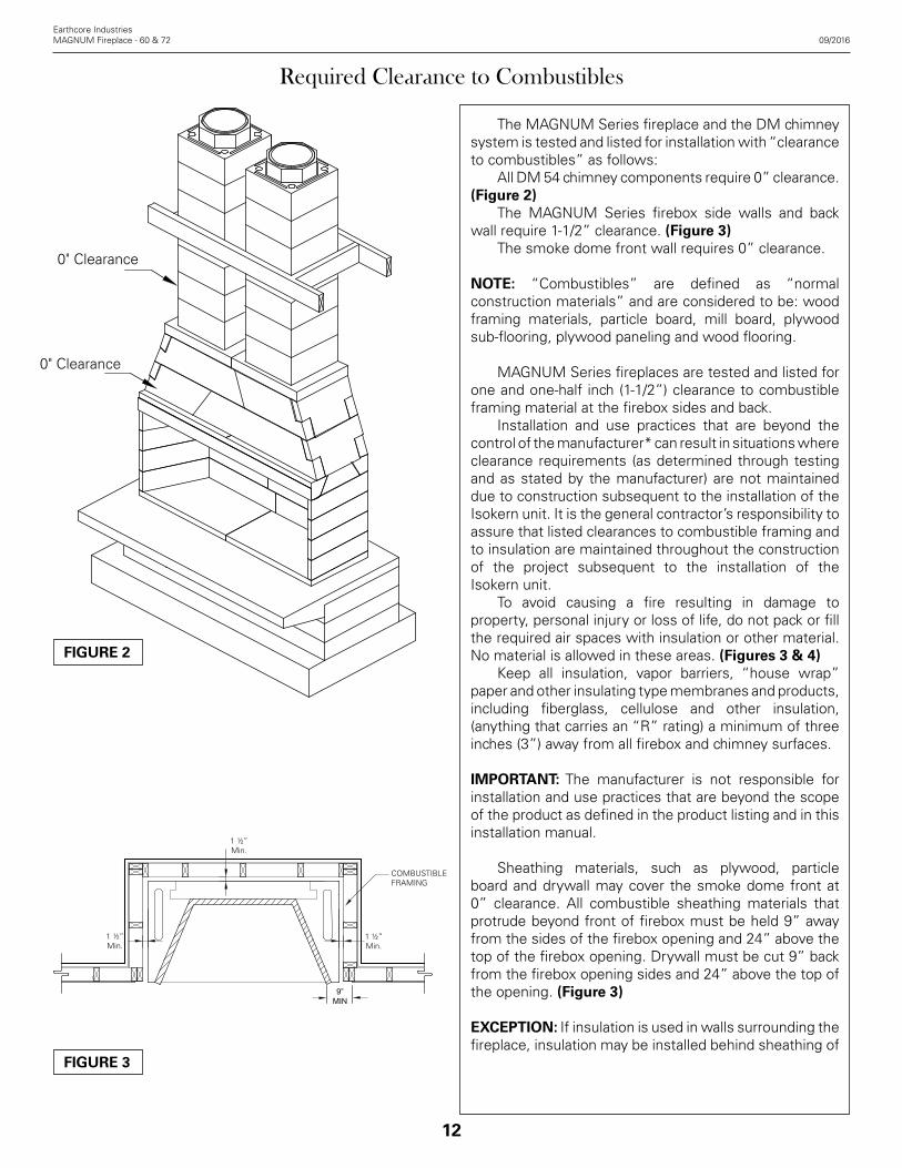
6. Set the rear smoke dome components across the damper beam in a bed of mortar and flush with the back face of the back damper beam lintel. Set the front smoke dome components in mortar across the front damper beam and 2 -3/4 inches back from the front of the front damper beam lintel. This placement should create a space of 17 inches (17”) between the front and rear smoke dome components. (Figure 21)
7. Position the smoke dome’s sloping sidewalls at each end of the smoke dome components. The sloping sidewalls fit in between the front and rear smoke dome components and also fit into the haunches at the ends of the front and rear smoke dome components. Mortar all contact surfaces thoroughly. The smoke dome sloping sidewalls have a beveled bottom edge so that they will sit tight onto the flat top of the damper beam assembly. (Figure 22)
8. Set the second tier of rear smoke dome components across the top of the first tier of smoke dome components with mortar between the two tiers. Making sure both tiers are flush with one another. Follow the same instructions of the second tier of rear smoke dome components for the second tier of front smoke dome components. This placement should create a space of 17 inches (17”) between the front and rear smoke dome components. (Figure 23)
FIGURE 21
2 ¾”
Part #16
Part #15
Part #15
Part #16
Part #34
Part #34
FIGURE 22
FIGURE 23
Part #15
Part #15
Part #17
Part #17

21
9. Position the second tier of smoke dome’s sloping sidewalls at each end of the smoke dome components. The sloping sidewalls fit in between the front and rear smoke dome components and also fit into the haunches at the ends of the front and rear smoke dome components. Mortar all contact surfaces thoroughly. The smoke dome sloping sidewalls have a beveled bottom edge so that they will sit tight onto the flat top of the damper beam assembly. (Figure 24)
10. Set the two top plates into position and mortar on top of the smoke dome wall assembly. One side of the top plate shows a thickened center. This side is the bottom face. The flue hole in the top plate is centered in the smoke dome from side to side but is offset from front to back, the center being ten and three-fourths inches (10 ¾”) from the back of the firebox. (Figure 25)
Earthcore Industries09/2016 MAGNUM Fireplace - 60 & 72
Assembly Instructions - MAGNUM Series 60"
Part #34
Part #34
FIGURE 24
FIGURE 25
Part #79L
Part #79R
Part #34
Part #34Part #16
Part #15
Part #15
Part #17
Part #90
Part #94RPart #74
Part #75
Part #72
Part #71
Part #96
Part #91

22
Earthcore IndustriesMAGNUM Fireplace - 60 & 72 09/2016
Assembly Instructions - MAGNUM Series 72"
The following assembly instructions identify the parts by name, part number and the placement of each part in the assembly process.
NOTE: At all component placement, be sure to mortar all contact surfaces with Earthcore Mortar. Check for complete sealing of each contact joint while assembly progresses.
1. Apply mortar to the joint between the two part #91's and set the base plates in a full bed of Earthcore Mortar on a level support surface. See page 14 for supporting floor system. (Figure 26). Do not set the base plate so that it is in span. The overall length of the base plate assembly should measure 851/2” and 28" deep.
NOTE: The Isokern base plate must be used in all Isokern MAGNUM installations.
2. Set the first course of the firebox side walls and back walls into place. (Figure 27 - 28)
NOTE: It may be convenient to dry set the first course of side walls and back walls into place on the Isokern base plate and then trace their position on the base plate with a pencil. After outlining the dry set pieces, remove them and apply Earthcore Mortar to the areas traced on the base plate where the side walls and back wall are to sit. By doing this, the first layer of wall components can be set directly into mortar already applied to the proper areas on the base plate.
FIGURE 26
FIGURE 27
FIGURE 28
Part #91
Part #91
Part #90
Part #90
Part #90
Part #72
Part #73
Earthcore Mortar

23
3. Continue assembly of the consecutive courses of the firebox side wall and back wall, making sure to stagger the backwall components so that the vertical joints do not align. Apply mortar to the top of each layer of wall components, set the next course above into place. Be sure to mortar all vertical joints of the side wall to back wall connection when setting each component to its mate. (Figure 29) Look for some mortar to squeeze out along the joints of all contact surfaces as a sign that the joint is thoroughly sealed with the approved mortar.
4. When all of the firebox sidewall and backwall components are set, check the top surface of the firebox for level. If necessary, adjust the top surface of the box assembly for level by inserting a shim supplied with the unit between the lowest wall component and the top surface of the base plate. Any gap created under the wall components during the Shim leveling process must be filled with Earthcore Mortar to fill bearing against the base plate.
5. Steel angle iron with measurements of 4” x 6” x 5/16” cut to 851/2” long to span firebox opening will be needed to assemble the firebox. This item is not included in the components and can be sourced locally. This steel angle sits on top of the uppermost side wall component with the four inch leg in the horizontal position. To avoid a thickness problem with the placement of the steel angle it is necessary to cut a notch in the top side wall component where the angle is to sit. This notch should be cut approximately 5/16” deep. The notch should start at the front face of the side wall component (at both the left and right hand walls) and run to a point 4” back toward the firebox. (Figure 30) The steel angle sits in this notch. The six inch leg of the steel angle is in the vertical position and is to be located in alignment with the front of the firebox. The ends of the steel angle should not protrude beyond the outer firebox side wall. Mortar between the steel and the notch in the top of the side wall is not needed.
Earthcore Industries09/2016 MAGNUM Fireplace - 60 & 72
Assembly Instructions - MAGNUM Series 72"
FIGURE 29
4”
5/16”
Part #90
Part #90
Part #72
Part #73
FIGURE 30

24
Earthcore IndustriesMAGNUM Fireplace - 60 & 72 09/2016
Assembly Instructions - MAGNUM Series 72"
5. The fireplaces come with an eight inch (8”) thick damper beam assembly, an six (6) piece component group that is to be assembled on top of the firebox sidewalls and backwall. The damper beam assembly consists of four (4) long lintel pieces and two (2) short damper beam side pieces. The damper side pieces are designed to sit on the firebox side wall between the front lintel and the back lintel. Each of the damper side pieces is designed specifically for its own side of the unit. When properly set, each damper side piece fits flush with the outside face of the firebox sidewall so that its interior bottom edge aligns with the interior angle of the firebox side wall that it sits on. (Figure 31) The four (4) lintels when part# 75 and part#84 are put together they will be equal to the width of the fireplace model that they serve. Properly placed, the lintel is to sit on top of the firebox back wall and flush with it; the other lintel sits flush with the front of the firebox, spanning the firebox opening. These components both sit on their narrow base so that their beveled face points down and into the firebox interior. (Figure 32) Be sure to mortar all damper beam components to the top surfaces of the firebox. Mortar the contact surfaces of each damper side component where it meets the front and back damper beam lintel components.
FIGURE 31
FIGURE 32
Part #83
Part #84
Part #94L
Part #83
Part #84
Part #84
Part #94L
Part #94R
Part #83

25
6. Set the rear smoke dome components across the damper beam in a bed of mortar and flush with the back face of the back damper beam lintel. Set the front smoke dome components in mortar across the front damper beam and 2 -3/4 inches back from the front of the front damper beam lintel. This placement should create a space of 17 inches (17”) between the front and rear smoke dome components. (Figure 33)
7. Position the smoke dome’s sloping sidewalls at each end of the smoke dome components. The sloping sidewalls fit in between the front and rear smoke dome components and also fit into the haunches at the ends of the front and rear smoke dome components. Mortar all contact surfaces thoroughly. The smoke dome sloping sidewalls have a beveled bottom edge so that they will sit tight onto the flat top of the damper beam assembly. (Figure 34)
8. Set the second tier of rear smoke dome components across the top of the first tier of smoke dome components with mortar between the two tiers. Making sure both tiers are flush with one another. Follow the same instructions of the second tier of rear smoke dome components for the second tier of front smoke dome components. This placement should create a space of 17 inches (17”) between the front and rear smoke dome components. (Figure 35)
Earthcore Industries09/2016 MAGNUM Fireplace - 60 & 72
Assembly Instructions - MAGNUM Series 72"
2 ¾”
Part #16
Part #18
Part #18
Part #16
Part #34
Part #34
FIGURE 33
FIGURE 34
FIGURE 35
Part #19
Part #19
Part #16Part #16

26
Earthcore IndustriesMAGNUM Fireplace - 60 & 72 09/2016
Assembly Instructions - MAGNUM Series 72"
9. Position the second tier of smoke dome’s sloping sidewalls at each end of the smoke dome components. The sloping sidewalls fit in between the front and rear smoke dome components and also fit into the haunches at the ends of the front and rear smoke dome components. Mortar all contact surfaces thoroughly. The smoke dome sloping sidewalls have a beveled bottom edge so that they will sit tight onto the flat top of the damper beam assembly. (Figure 36)
10. Set the two top plates into position and mortar on top of the smoke dome wall assembly. One side of the top plate shows a thickened center. This side is the bottom face. The flue hole in the top plate is centered in the smoke dome from side to side but is offset from front to back, the center being ten and three-fourths inches (10 ¾”) from the back of the firebox. (Figure 37)
FIGURE 36
Part #34
Part #34
Part #77A
Part #77A
FIGURE 37
Part #34
Part #90
Part #94R
Part #91
Part #91
Part #18
Part #16
Part #19
Part #16
Part #34
Part #73
Part #72
Part #83
Part #84

27
The DM chimney is a dual module, refractory masonry chimney system. It is composed of two precast mating components, the outer casing liner and an inner liner. This chimney system is designed for installation in accordance with the National Fire Protection Standard for Chimneys and Solid Fuel-Burning Appliances, NFPA 211 and in accordance with codes such as ICC, BOCA Basic/National Codes, the standard Mechanical Code and the Uniform Building Codes.
Required DM Chimney Clearance The DM chimney system, rated UL 103HT, is listed for zero clearance to normal construction materials. The DM chimney system may be enclosed in a wood chimney chase at zero clearance to wood framing members. Since lateral support is required for DM chimneys the framing members will be in contact with the DM chimney system.
IMPORTANT: “Combustibles” are defined as “normal construction materials” and are considered to be: framing materials, particle board, mill board, drywall, plywood paneling, plywood sub flooring, and wood flooring. Keep all insulation, vapor barriers, “house wrap” paper and other insulating type membranes and products, including fiberglass, cellulose and other insulation, (anything that carries an “R” rating) a minimum of three inches (3”) away from all firebox and chimney surfaces.
EXCEPTION: If insulation is used in walls surrounding the fireplace, insulation may be installed behind sheathing of gypsum board, plywood, particle board or other material on the side facing the Isokern. The facing material cannot be within 1 1/2” to the fireplace sidewalls.
Mechanical Vent SystemsIt is acceptable to use mechanical draft systems, if the venting companies do the engineering calculations and make the necessary recommendations for fan size and flue vent diameter following the guidelines of NFPA 211/2006, pg. 211-13. Installation of such systems must also follow the mechanical drafting company’s explicit installation and operation instructions.
Isokern DM Chimney Weights Total installed chimney weight will vary and be based on the overall height and the configuration of the chimney system. Chimneys may be straight vertical stacks of DM outer casing and inner liner (22’-0” Maximum without additional structural support) but may also include the use of offset chimney blocks, brick ledge, chimney reinforcement, brick/stone veneers, cement crown caps and clay chimney pot termination.
Earthcore Industries09/2016 MAGNUM Fireplace - 60 & 72
DM Chimney Components & General Information
Component Part# Description
12”
16 ½”
14”
6”
16 ½”14”
21 ½” 21 ½”
12”
21 ½”25”
6”
70003 Isokern DM Chimney 6" Inner Liner
70235 Isokern DM Chimney 12" Inner Liner
45433 Isokern DM Chimney 12" Outer Liner
40136 Isokern DM Chimney Offset Block
40322 Isokern DM Chimney Small Crown Cap
(for Stucco Application)
50001
50003
ISO-Cap Spark Arrestor -Stainless Steel
ISO-Cap Spark Arrestor w/Damper -Stainless Steel (Shown)
31½”31½”
3”
50006 ISO-Cap Spark Arrestor -Copper
50004 ISO-Cap Spark Arrestor -Black Galvanized

28
Earthcore IndustriesMAGNUM Fireplace - 60 & 72 09/2016
10’-0”
LESS THAN 10’-0”
CRICKET 3’-0
” M
IN ROOF RIDGE
WORK POINT
SECTIONTHRU ROOF
CHIMNEY2’
-0”
WORKPOINT
CRICKET
CHIMNEY
3’-0
” M
IN
SECTIONTHRU ROOF
2’-0
”
3’-0
” M
IN
Chimney Height Requirements
The required minimum chimney height above the roof and adjacent walls and buildings is specified by all major building codes and is summed up in what is known as “the 2 foot in 10 foot rule”: (1) If the horizontal distance from the roof ridge to the opening of the chimney is less than 10’, the top of the chimney must be at least 2’ above the roof ridge (Figure 99). (2) If the horizontal distance from the opening of the chimney to the roof ridge is more than 10’ then a chimney height “work point” is established on the roof surface 10’ horizontally from the opening of the chimney. The top of the chimney must be at least 2’ above this work point (Figure 100). (3) In all cases, the chimney cannot be less than 3’ above the roof at the edge of the chimney. (Figures 38 & 39) A simple example of this would be if the roof is flat then the chimney would need to be at least 3’ above the roof surface. Or, if the chimney penetrates the roof at the ridge then the chimney must be at least 3’ above the ridge. (Figure 40)
NOTE: The “2 foot in 10 foot rule” is necessary in the interest of fire safety but does not ensure smoke-free operation of the fireplace. Trees, buildings, adjoining roof lines, adverse wind conditions, etc. may require a taller chimney for the fireplace to draft properly.
As with all chimney installations, avoid overhead obstructions such as trees, power lines, etc.
FIGURE 38
FIGURE 39
FIGURE 40

29
DM Chimney Installation - Straight Run
Where the chimney run is to be straight run the DM chimney by setting a DM outer liner in a bed of mortar on top of the MAGNUM top plate where the outer liner is centered from side to side and flush with the back of the top plate. Be sure that the outer liner aligns with the flue hole in the top plate. Set in this way the DM outer liner will sit three and three fourths inches (3¾”) back from the front face of the top plate. This total set-back distance makes it possible for a three and one-half inches (31/2”) thick bearing header to pass over the MAGNUM firebox smoke dome assembly and for the DM chimney to run straight up the back side of the bearing header. (Figure 41) Next set the DM chimney inner liner’s six inch (6”) tall "starter" piece inside the first outer liner. The six inch (6”) tall inner liner has a female end and a flat end. Set this inner liner with the flat end down. Be sure that the stater piece is set into the Earthcore Mortar so it is fully sealed to the top plate. IMPORTANT: Mortar all outer liners together and mortar all inner liners together. Do not mortar the air space between the liners and the outer casing blocks.
Starting with the six inch (6”) tall inner liner starter piece creates six inch (6”) staggered horizontal joints between the inner liner and the outer liner as the chimney is built up. Both the outer liner and the inner liner components have tongue and groove type detailing on each end to assure alignment and interlock of the pieces as they are stacked and glued together.
NOTE: If the six inch (6") inner liner starter piece is broken or otherwise unavailable then a full twelve inch (12”) tall inner liner piece can be cut to six inches (6”) in height to make an inner liner starter piece.
After setting the DM inner liner starter piece, apply mortar to the top of the starter liner. Continue the straight chimney run by placing a full height inner liner onto the six inch (6”) starter liner. The top of this full height inner liner will sit 6” above the top of the outer casing block that was previously set. This six inch (6”) offset between joints of the inner liner stack and the joints of the outer casing stack continues to the top of the chimney run. (Figure 42) Continue the straight vertical DM chimney by setting an outer liner onto the mortared top surface of the preceding outer liner. The grooves on the bottom end of the upper outer liner fit onto the tongues on the top of the lower outer casing block. This assures proper alignment of the two components.
Earthcore Industries09/2016 MAGNUM Fireplace - 60 & 72
Part #45433
Part #70003
Part #70235
Part #45433
FIGURE 41
FIGURE 42

30
Earthcore IndustriesMAGNUM Fireplace - 60 & 72 09/2016
FIGURE 43
FIGURE 44
Next place a full height inner liner onto the mortared top end of the previously set inner liner. Proceed this alternate stacking of outer liner and inner liners until the desired height of the flue is attained.
Lateral Support for DM Chimneys Though not required, it is recommended that where the DM chimney is built up along an exterior wall the vertical chimney system can be connected to the structural wall system at a minimum of four foot (4’) intervals. This connection can be made using 18 gauge strap ties (Simpson Strong Tie CS coil strap, or equivalent). Starting on one side of the DM chimney, at four foot (4’) intervals up the structural wall adjoining the chimney, connect one 18 gauge strap tie to the structural wall with two, three inch (3”) #8 (minimum) wood screws or masonry anchors, as appropriate. Next fold the strap around the three exposed sides of the outer casing. Connect the strap to each of the three outer casing faces with two, one and one-half inch (1-1/2”) long masonry anchors, such as “Tapcon” or “Titen” screws. Fasten the strap back to the structural wall with two three inch (3”) # 8 (minimum) wood screws or masonry screws, as appropriate. (Figure 43) Where DM chimneys are built up from the interior walls the DM chimney outer casing block is to be laterally braced at ceiling and roof penetrations. Pressure treated two inch (2”) by four inch (4”) blocks, set at each side of the flue between the trusses or rafters and fastened to the pre-engineered roof trusses or rafters with two 16d common nails at each end, provides lateral support, parallel with the framing. Additionally, a two inch (2”) by four inch (4”) by six feet (6’) minimum pressure treated member (“rat run”) installed on each side of and butted up to the outer casing block will provide lateral support perpendicular to the direction of the truss or rafter framing system. Fasten the perpendicular member with two 16d common nails to each intersecting truss or rafter. The perpendicular bracing should be installed on the top side the ceiling level framing as well as on the bottom side of the rafters. (Figure 44)
DM Chimney Installation - Straight Run

31
Earthcore Industries09/2016 MAGNUM Fireplace - 60 & 72
31
DM Chimney Installation - Offset Run
DM Offset Block For vertical DM chimney to bypass overhead obstructions, the Isokern offset chimney block is used. Offset blocks are six inch (6”) thick, single module chimney components, measuring twenty-one and one-half inch (21-1/2”) wide by twenty-five inches (25”) long. The fourteen inch hole passes through the block at thirty (30°) degrees. An offset chimney block can be set as the first flue component on top of the MAGNUM top plate. Offset chimney block sequences can be built to shift the chimney run to the left, right or to the rear of the firebox/smoke dome assembly. Offset blocks can be set in a spiraling rotation, thus moving the chimney to a point that is diagonally away from its starting point. Offset blocks require 1 1/2” to combustible framing. DM Chimney Offset Block Installation and Support Foundations Isokern offset chimney blocks are stacked in a stair step fashion with each successive block overhanging the previous offset block by three inches (3”), allowing the flue to rise at an angle of thirty (30°) degrees off of vertical. (Figure 83) Each offset block is to be set fully in a bed of Earthcore Mortar, completely sealing each offset block to the underlying component. When placing the first inner liner on top of the last offset required, seal the space between the inner liner and the offset block so that no smoke will be able to spill through the two joints. When building offset sequences it is necessary to support the third offset block in the sequence and every third offset block thereafter to footings via concrete block or steel support columns. When using only one or two offset blocks no additional support is required. During this building process it is important to check the interior flue alignment as each offset block is set to avoid creating overhanging ledges on the inside of the flue. Such internal overhangs will inhibit flue drafting. Offset sequences are best when built as low as possible in the chimney run to maximize performance. If a DM Offset sequence can not be done at the beginning of the chimney sequence, you must consult a structural engineer to ensure proper support is in place for the DM Chimney Offset. Plan fireplace and DM chimney systems carefully before foundations are laid to assure that proper footings are available to support Isokern offset blocks chimney run. To calculate the distance of Isokern offset chimney travel in a straight line to the right, left or to the rear of the firebox/smoke dome assembly, proceed as follows: Temporarily dry set a DM outer casing block in its proper location on top of the completed firebox/smoke dome assembly as though starting a straight chimney.(Figure 46)
FIGURE 45
FIGURE 46
3"
PLUMBLINE
MEASURE TRAVEL DISTANCE
OVERHEADOBSTRUCTION
TRAVEL DISTANCE

32
Earthcore IndustriesMAGNUM Fireplace - 60 & 72 09/2016
32
If the offset sequence is to move to the left then, starting from the right side of the temporary DM outer casing measure left ward to the far face of the overhead obstruction that needs to be bypassed by the vertical chimney run. For accurate measuring drop a plumb line down from the far face of overhead obstruction to the level of the top of the smoke dome assembly. Measure from the far side of the temporary DM outer casing to the plumb line. This measurement, taken in inches and divided by three (three inches of horizontal travel per offset block) gives the total number of offset blocks needed to accomplish the required travel distance. To calculate the height that the offset block sequence will require, take the total number of offset blocks needed to accomplish the travel distance (described above) multiplied by 6”. This number is the height (inches) that the offset sequence will require. When establishing the “far face” of the overhead obstruction, be sure that the DM chimney blocks can run straight to chimney termination without further overhead obstruction since a second offset sequence is not allowed. (Figure 42 & 43) Be sure that there is sufficient space beyond the “far face” of the overhead obstruction to accept the DM chimney’s outer casing dimension of 21 1/2”. IMPORTANT: Always support the last offset block in a sequence for full support of the DM chimney where it returns to vertical.
Support columns often carry the majority of the total load of the vertical chimney that is set onto the last offset block. The total chimney weight above the last offset blockwill be the total weight of the vertical chimney plus any additional allowable loads such as the Isokern brick ledge, its related brick or stone veneers, and any crown caps, clay pots or other masonry chimney terminations. Be sure the foundation under all support columns is made of concrete or steel and designed to support the loads applied to it. Do not make support columns of brick, stone or wood. All support columns must bear onto proper non-combustible foundations.
DM Chimney Installation - Offset Run
PLUMBLINE
MEASURE TRAVEL DISTANCE
OVERHEADOBSTRUCTION
TRAVEL DISTANCE
FIGURE 47
FIGURE 48

33
Earthcore Industries09/2016 MAGNUM Fireplace - 60 & 72
33
DM Chimney Installation - Offset Run
Offsets to the Left or Right: When offsetting chimneys to the left or right of the firebox it is not possible to build a support column directly under the third offset block. To create proper support, construct a support column against the firebox from bearing up to the level of the smoke dome. Bridge from the column over to bearing on the smoke dome with two pieces of four inch (4”) by four inch (4”) by five-eighths inch (5/8”) steel angle. On the steel angles build a masonry or steel support column up to the underside of the third offset block in the sequence. (Figure 49)
NOTE: For offset chimney block sequences that clear the side wall of the firebox below, it is allowable to support the first offset block that clears the firebox side wall and then to proceed with supports at each third offset block thereafter. (Figure 47)
FIGURE 49

BRICK LEDGE
ISOKERNBRICKLEDGE
34
Earthcore IndustriesMAGNUM Fireplace - 60 & 72 09/2016
The DM brick ledge is a 3” thick, 32-1/2” square, steel reinforced, concrete and pumice slab (Figure 91). It provides a 5” ledge at all four sides of the outer liner block and is designed to support masonry veneers to DM chimneys starting below the rafters and continuing to termination. (Figure 47) The component is cast with an octagonal hole in itscenter so that the DM octagonal inner liner can pass through it. The brick ledge has four 2-1/2” holes through it that align with the hole in each of the four corners of the DM outer liner block. These four holes are provided for reinforcement of the chimney stack by the insertion of #4, minimum, steel reinforcing rods and subsequent grouting. (Figure 48) The brick ledge is intended for use in chimneys that rise through the roof only where all four sides of the chimney are bounded by the roof.
IMPORTANT: To maintain structural performance the DM brick ledge must not be cut or altered in any way.
DM Brick Ledge Installation Use of the brick ledge will require a roof framing rough opening of at least 34” in width. The required opening dimension along the length of the rafter, where the chimney is to penetrate the roof line, will increase above 34” relative to the pitch of the roof. As the DM outer casing and inner liner assembly approaches the roof penetration set an outer casing block to a level of approximately 6” below the low side of the roof framing. (Figure 49) The alignment tongues on the top of this outer casing block must be ground off to leave a flat contact surface for the brick ledge. Temporarily leave out the inner liner that fits this outer casing block. Set the Isokern brick ledge onto the flat top surface of the outer casing in a full bed of Earthcore Mortar. Be sure to align the four 2-1/2” holes in the brick ledge with the matching holes in the outer liner block below it. Return to setting the next inner liner in the sequence. This inner liner comes up from below and passes through the octagonal hole in the brick ledge. The liner’s top end will be approximately 3” above the top surface of the brick ledge. Set the next outer liner block onto the top of the brick ledge in a bed of Earthcore Mortar. Insert one piece of #4 (minimum) steel reinforcing rod into each of the four 2-1/2” holes in the brick ledge. The reinforcement rods must start from a depth of at least 18” below the bottom of the brick ledge. (In some cases, a minimum recommendation could be 5’) Consult local structural engineer for proper job specific support structure design, sizing and load bearing specifications for the MAGNUM Models 82060 & 82072.
34
DM Brick Ledge
FIGURE 50
FIGURE 51

35
If short lengths of steel rods are used be sure to properly lap and wire tie all splices in the rebar. As the reinforcing progresses, completely fill the holes with grout. Suitable grout can be a pourable mixture of Portland cement and sand or Portland cement, sand and pea gravel. The rebar must be fully embedded in grout. Leave enough of the #4 steel reinforcing rod exposed above the brick ledge so that as the stacking of outer casing blocks continues to termination the reinforcing rods and grout can continue through the stack. Reinforcing shall continue to chimney termination. All DM chimneys that include the DM brick ledge must be reinforced as described above.
NOTE: When installing the MAGNUM 60" Fireplace the Isokern Brickledge will NOT work due to space constraints of the two DM 54 Chimney Flues without the use of chimney offset blocks. A six inch offset is needed on both DM54 Chimney Flues to use the Brickledge. If you have any questions or concerns, contact Earthcore Industries at 1-800-642-2920
CAUTION: When using the Isokern brick ledge it is required that the MAGNUM firebox/smoke dome assembly include the placement of a 4” by 4” by 3/8” minimum steel angle across the firebox opening. (See page 48 for “Structural Information” for details regarding specification and placement of steel angles in MAGNUM fireplaces.)
Lateral Support for Isokern Brick ledge Chimneys Once the DM chimney and brick ledge are assembled and after the intended masonry veneer has been installed on the brick ledge, be sure to brace the chimney following the guidelines on page 29 of this manual for Lateral Support of DM chimneys.
Load Capacity for DM Brick ledge The sources of load delivered into the Isokern brick ledge are: (1) the total physical load of brick, stone or other masonry veneer on the brick ledge, and (2) loading due to the force of wind delivered against the exposed height of the chimney mass. The required height of any chimney is governed by applicable local building codes. The overall finished height of any chimney varies based upon site-specific conditions (eg. elevation of roof line, roof pitch, distance of the chimney from the ridge, etc.). It is relatively simple to calculate the total physical load on the brick ledge resulting from the physical weight of applied veneers built to code height. However, calculation values for load to the brick ledge due to wind are site specific and based on local variables such as wind speed zone, exposure classification, eave height and roof pitch of the structure, as well as height of chimney mass exposed to wind.
Earthcore Industries09/2016 MAGNUM Fireplace - 60 & 72
35
DM Brick Ledge
ISOKERNBRICKLEDGE
FIGURE 52

36
Earthcore IndustriesMAGNUM Fireplace - 60 & 72 09/2016
36
DM Brick Ledge
IMPORTANT: The total load delivered into the brick ledge is job specific and will be the sum of: (1) the physical load from veneers, plus (2) the load due to wind.
IMPORTANT: Do not subject the brick ledge to unequal loading when applying veneers. Build veneers equally on all four sides of the brick ledge.
Brick ledge Veneer Finish and Flashing Details When applying brick, stone or other masonry veneer to the Isokern brick ledge standard good building practices for masonry veneer work should govern weather-proofing details and the placement of flashings. A typical flashing detail would be to field fabricate an aluminum or galvanized sheet metal flashing, approximately thirty-two inches (32”) square with a twenty inch (20”) square hole in it, to serve as an inner flashing. Place the inner flashing on the first DM outer casing block that fully clears the roof line. Keep the flashing to about a one-half inch (1/2”) lap onto the top of the outer casing block. The twenty inch (20”) square hole in the flashing should fit to the outside of the alignment grooves on top of the DM outer casing. Continue the DM chimney up to the required termination height. Once the masonry veneer is in progress the inner flashing is set into a horizontal joint in the veneer at a level above all other roof deck flashings, chimney-to-roof flashings and counter flashings. Weep holes should open to the outer face of the veneer at vertical mortar joints located at the level of the inner flashing. (Figure 53) Where moisture may develop between the DM outer casing and the chimney veneer, inner flashings as described above will help to divert such moisture to exterior face of the veneer by way of the weep holes and thereby keep such moisture from working its way down between the veneer facing and the DM outer casing and into the interior of the structure below.
FIGURE 53

37
ISO-Cap The Iso-Cap is a Spark Arrestor/Rain Cap designed to fit atop the Isokern DM 54 Chimney Inner Liner and is available in Stainless Steel, Black Galvanized, Copper or a Stianless Steel with Damper. (Figure 54) A 14" diameter sleeve projects from the bottom of the ISO-Cap and inserts into the DM 54 Inne Liner. A two inch (2") wide flange at the base of the ISO-Cap cover the top surface of the DM 54 Inn Liner to protect the liner from weather. To Install the ISO-Cap silicone caulk is used to adhere the two inch (2") flange to the top of the DM 54 Inner Liner.
Elemental Clay Pots The Elemental Clay Pots are set in a bed of mortar on the DM 54 Chimney Inner Liner. The base of the chimney top need not match the dimensions of the inner liner it is being installed on top of, but should not impinge on the inside area of the flue liner except for the maximum 3/4 of an inch in the corners. The flue liner may extend up inside the chimney top, or the flue liner may be flush with the top surface of the chimney cap. Additional anchoring may be used to prevent damage from tornadoes, hurricanes or earthquakes. A 1/4 - 1/2 inch diameter hole may be drilled in at least two opposite sides of the chimney top and a bar used to anchor the top into the grout or the chimney walls.
NOTE: The Elemental Clay Pots can only be installed on the DM54 Chimney System. The Clay Pots are not tested and listed for use with Metal Chimney Flue Systems.
Custom Chimney Caps A non-combustible, weather tight chase flashing must be used to cover the top of the chimney chase. Be sure to seal the joint where the DM liner passes through the chase top flashing for positive weather seal. Chase flashings may be supplied by others. Special design caps may be designed and constructed by others and must be fashioned so as not to restrict the flow of smoke and gases out the top of the flue opening. The figure below depicts common chimney terminations. (Figure 56) Check with local building codes to establish the need for chimney caps and spark arrestors or for any limitations to their design and use.
Earthcore Industries09/2016 MAGNUM Fireplace - 60 & 72
DM 54 Chimney Terminations
FIGURE 56
FIGURE 54
FIGURE 55

38
Earthcore IndustriesMAGNUM Fireplace - 60 & 72 09/2016
Metal Chimney Flue
The MAGNUM Series Fireplaces are tested and listed for use with factory-built metal UL 103 or Class A metal chimney systems. The design and installation require that the system use the Isokern ECO-STEEL chimney, FTF-13 metal flue or UL listed steel chimney offered by multiple manufacturers, see below for approved manufacturers. PREFERREDECO-STEEL®(UL 103) by Earthcore Air Cooled Chimney
Other Approved ManufacturersTemp Guard(UL 103) by Metal-Fab Insulated ChimneyFTF-13(UL 127) by IHP® Air Cooled ChimneyDuraChimney® (UL 103) II by DuraVent® -Air Cooled ChimneyDuraTech® (UL 103) by DuraVent® Insulated ChimneyGalva-Temp® (UL 103) by Selkirk® Insulated Chimney
Metal Flue Types The selected factory-built metal chimney for use with the fireplaces, at a minimum, must be listed by a recognized agency for solid fuel and as tested to UL 103, for continuous use of one thousand degrees (1000°) Fahrenheit and intermittent use of seventeen hundred degrees (1700°) Fahrenheit.
The factory-built metal flue design can be from the following types:
1. Non-insulated completely thermal siphoning, double-wall, air-cooled solid fuel rated chimneys listed to UL 103, UL 127 & ULC S-629.
2. Double-wall with solid-pack insulation.
NOTE: The selected, approved chimney manufacturer must provide the masonry anchor plate designed to fit their flue system. (Figure 57) All chimneys and chimney liners must be installed in accordance with the manufacturer’s installation instructions and under the terms of their listing for use with open faced fireplaces. Maximum height of a metal flue system is not required as all the load can be taken off the firebox. Refer to metal flue manufacturer for number of offsets, approved chimney shrouds, clearance to combustibles and any information specific to that flue system. Only tested and listed chimney terminations can be used on metal flue chimney systems.
ECO-STEEL Metal Flue
FIGURE 57
Anchor Plate

39
Earthcore Industries09/2016 MAGNUM Fireplace - 60 & 72
Components List - ECO-STEEL Metal Chimney Flue
Component Part# Description
13ECO48 ECO-STEEL 48" Chimney Flue
13ECO36 ECO-STEEL 36" Chimney Flue
13ECO18 ECO-STEEL 18" Chimney Flue
13ECO12 ECO-STEEL 12" Chimney Flue
Component Part# Description
13ECO30OS ECO-STEEL 30 Degree Offset
13ECOAP ECO-STEEL Anchor Plate
13ECOAPD ECO-STEEL Anchor Plate w/Damper
13ECOFS ECO-STEEL Firestop
13ECOCTF ECO-STEEL Chase Top Flashing
13ECOTCF ECO-STEEL Tall Cone Flashing
13ECOCC ECO-STEEL Round Chimney Cap
13ECOWB ECO-STEEL Wall Band
13ECO15OS ECO-STEEL 15 Degree Offset
13ECOSC ECO-STEEL Storm Collar
13ECOSB ECO-STEEL Support Band

40
Earthcore IndustriesMAGNUM Fireplace - 60 & 72 09/2016
ECO-STEEL General Information
Earthcore Air-Cooled ECO-STEEL Chimney is not designed for use on products that operate at continuous temperatures in excess of 1000°F. Creosote and Soot – Formation and Need for RemovalWhen wood is burned slowly, it produces tar and other organic vapors, which combine with expelled moisture to create creosote. The creosote vapors condense in the relatively cool chimney flue of the slow burning fire. As a result, creosote residue accumulates on the flue lining. When ignited, the creosote makes an extremely hot fire. The chimney should be inspected at least once every two (2) months during the heating season to determine if a creosote or soot buildup has occurred. If creosote or soot has accumulated, it should be removed to reduce the risk of chimney fire. Chimneys must be installed so that access is provided for inspection and cleaning. Never fill any required clearance space with insulation or any other building materials surrounding the chimney. Do not use a fireplace for food grilling. Grease from foods can collect in chimney causing fireplace to become a potential fire hazard. Some chemical Chimney cleaners can be harmful to the chimney. These cause accelerated oxidation or corrosion. If chemical cleaners are used, they must be non-corrosive in nature. If a brush is used, it must be of proper size with plastic bristles. Have your chimney cleaned by a professional, certified chimney sweep. If a flue fire occurs, close all possible air inlets, and call your Fire Department. Do not use the chimney again until it has been inspected by a Certified Chimney Sweep for possible damage. Exterior metal parts, with exception of the top portion of the chimney cap, can be painted with a high temperature rust proof paint. Wash the metal surface with a vinegar and water solution to remove any residue before painting. Painting the chimney will help to increase chimney life. Earthcore assumes no liability for structural damage or roof contamination as the result of creosote formation. It is the owner’s responsibility to comply with inspection and cleaning requirements as described in these instructions, and those of the appliance manufacturer. Interior chimneys shall be enclosed where they extend through closets, storage areas, occupied spaces, or anywhere the surface of the chimney could be contacted by persons or combustible materials. The air space between the outer wall of the chimney and the enclosure shall not be less than 2 inches. Except for installation in one or two family dwellings, a factory built chimney that extends through any zone above that on which the connected appliance is located is to be provided with an enclosure having a fire resistance rating equal to or greater than that of the floor or roof assemblies through which it passes.
In cold climates, chimneys mounted on an outside wall should be enclosed in a chase. Exterior chases reduce condensation, creosote formation and enhance draft. Proper planning for your Earthcore Air-Cooled ECO-STEEL Chimney installation will result in greater safety, efficiency and convenience. You must use only ECO-STEEL Chimney parts and components to maintain a listed chimney system. Do not mix parts or try to match with other products or use improvised solutions. Install your Isokern fireplace as described in this installation manual and maintain all required clearances. Connect only one fireplace per chimney. Follow the fireplace safety manual for maximum efficiency and safety. Do not over fire. Any damage to the fireplace or chimney can possibly void the warranty. Do not burn driftwood, plastic, or chemically treated wood such as railroad ties. They are corrosive to your chimney system.
A MAJOR CAUSE OF CHIMNEY RELATED FIRES IS FAILURE TO MAINTAIN REQUIRED CLEARANCE (AIR SPACES) TO COMBUSTIBLE MATERIAL*. MINIMUM CLEARANCE FOR 13” DIAMETER AIR-COOLED ECO-STEEL CHIMNEY IS TWO (2) INCHES. IT IS OF UTMOST IMPORTANCE THAT THIS CHIMNEY IS INSTALLED ONLY IN ACCORDANCE WITH THESE INSTRUCTIONS.

41
1. Mount Anchor Plate: Chimneys for Isokern fireplaces begin with an Anchor Plate or Anchor Plate with Damper. It is important that the surface of the Isokern chimney has a level surface on which to attach the Anchor Plate. If the top of the Isokern does not have a level surface, then it will need to be modified accordingly. Center the Inswool blanket over Isokern Top Plate hole and trace outline of hole with a pen or marker. Cut a hole in the blanket to match the hole in the Isokern top plate. Center the Inswool blanket over the Isokern Top Plate flue opening, then center anchor plate over the Inswool blanket. If a Damper is used, make sure nothing interferes with the damper plate movement. Secure the Anchor Plate with four (4) masonry anchors. (Figure 58) If the Anchor Plate with Damper is installed the damper should swing freely. When the chain is pulled down, the damper should close (horizontal position). When the chain is released (no weight on the chain), the damper should swing open (vertical position). To install the lintel hook, place the damper plate in the closed (horizontal) position. Determine and mark the position of the lintel hook. The lintel hook should be mounted in a position so as to provide a small amount of tension in the spring attached to the chain. The tension is needed to prevent the damper plate from rattling when closed. Mount the lintel hook to masonry with the screws provided. Do not obstruct oval openings in the anchor plate.
WARNING: Do not locate Anchor Plate with Damper in a location inaccessible for inspection, cleaning and servicing after installation.
2. Attach the first section of chimney on the Anchor Plate. The joint assembly is a male to female slip fit and held together with four (4) sheet metal screws provided. (Figure 59) Do not penetrate the inner liner of the chimney when installing screws. Maintain a 2 inch (2") clearance to combustibles. Do not fill the clearance space with any materials. If an offset is required, refer to Elbow Offset Installation Section.
Earthcore Industries09/2016 MAGNUM Fireplace - 60 & 72
ECO-STEEL Metal Chimney Installation
FEMALE END
SELF-TAPPINGSCREWS (4 EACH)
MALE END
FIGURE 59
Anchor Plate
MasonryAnchors
Iso-wool
FIGURE 58
NOTE: Steel angle: 4” x 6” x 5/16” cut to span firebox opening. This item is not included in the components and can be sourced locally.
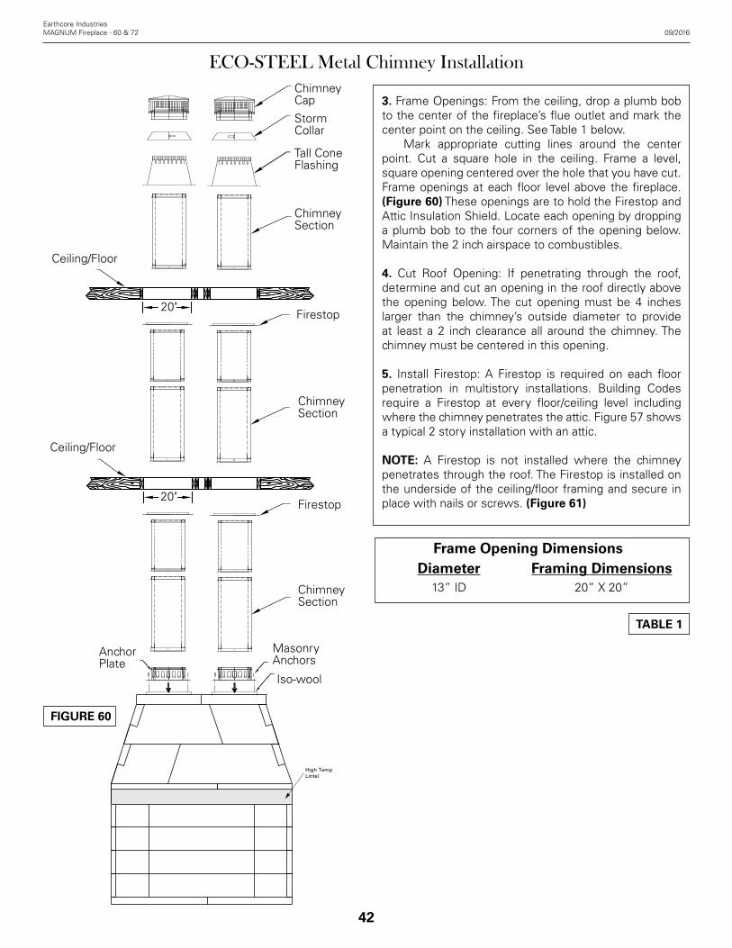
42
Earthcore IndustriesMAGNUM Fireplace - 60 & 72 09/2016
ECO-STEEL Metal Chimney Installation
3. Frame Openings: From the ceiling, drop a plumb bob to the center of the fireplace’s flue outlet and mark the center point on the ceiling. See Table 1 below. Mark appropriate cutting lines around the center point. Cut a square hole in the ceiling. Frame a level, square opening centered over the hole that you have cut. Frame openings at each floor level above the fireplace. (Figure 60) These openings are to hold the Firestop and Attic Insulation Shield. Locate each opening by dropping a plumb bob to the four corners of the opening below. Maintain the 2 inch airspace to combustibles.
4. Cut Roof Opening: If penetrating through the roof, determine and cut an opening in the roof directly above the opening below. The cut opening must be 4 inches larger than the chimney’s outside diameter to provide at least a 2 inch clearance all around the chimney. The chimney must be centered in this opening.
5. Install Firestop: A Firestop is required on each floor penetration in multistory installations. Building Codes require a Firestop at every floor/ceiling level including where the chimney penetrates the attic. Figure 57 shows a typical 2 story installation with an attic.
NOTE: A Firestop is not installed where the chimney penetrates through the roof. The Firestop is installed on the underside of the ceiling/floor framing and secure in place with nails or screws. (Figure 61)
Frame Opening DimensionsDiameter Framing Dimensions
13” ID 20” X 20”
High TempLintel
Anchor Plate
MasonryAnchors
Iso-wool
ChimneySection
Firestop
ChimneySection
Tall Cone Flashing
Storm Collar
ChimneyCap
20"
Ceiling/Floor
ChimneySection
Firestop
Ceiling/Floor
20"
FIGURE 60
TABLE 1

43
6. Support Band: Install an Support Band if total chimney height is greater than 50 feet, or if the fireplace manufacturer requires it. If additional support is needed, install one or more Supports which will support 30 feet of chimney. (Figure 63) Slide the Support Band around the chimney and align over framed opening. Secure to casing with four (4) sheet metal screws and assemble brackets. (Figure 62) Nail the brackets to the framing using a minimum of (2) nails or screws per bracket. A Wall Band may be required by some fireplace manufacturers to keep the chimney vertical and help maintain clearances to combustibles within a chase. Clamp the Wall Band to the pipe using the nut and bolt provided and secure legs to nearby framing using plumbers strap or guy wires. (Figure 64) The Support Band does not support the weight of the chimney, it is only used to keep the chimney centered within a chase.
Earthcore Industries09/2016 MAGNUM Fireplace - 60 & 72
ECO-STEEL Metal Chimney Installation
Firestop
Nut
Flat WasherLock Washer
Support Bracket
Support Band
Pilot Hole
Plumber’s Strap
Support BandChase
Floor/Ceiling
Chimney Section
Support Band
FIGURE 61
FIGURE 62
FIGURE 63
FIGURE 64
Per Table 1
Chimney Section

44
Earthcore IndustriesMAGNUM Fireplace - 60 & 72 09/2016
ECO-STEEL Metal Chimney Installation
7. Elbow Installation: 15° and 30° elbows are provided to allow chimneys to avoid framing members or roof peaks. A maximum of 30° from vertical is allowed and a total of two elbows for each chimney installation. A 2” clearance to combustibles must be maintained. If more than one (1) offset is needed, a mechanical exhaust fan should be used. The mechanical fan company would determine the viability of performance. Attach the elbow to the chimney pipe, support or other part. Using the offset chart, add chimney sections between elbows. A Support Band or plumbers strap is required for every 4 foot interval between elbows to support the load. (Figure 65) Attach the upper elbow to bring the chimney back to vertical. See TABLE 2 and Figure 66 for offset combinations.
“A”
“B”
“C”
Plumber’s Strap
Support Band
FirestopW/Integral Radiation
Shield
Plumber’s Strap
Support Band
4’ Max.
4’ Max.
ELBOW OFFSET CHART
13” Diameter
Elbow Angle
Length “A” “B” “C”
15°
0"0” 20-1/2” 2-1/2”
12” 30-1/2” 5-1/4”
18” 36-3/8” 6-3/4”
24” 42-1/8” 8-3/8”
36” 53-3/4” 11-3/8”
48” 65-3/8” 14-1/2”
30°
0” 23-5/8” 6”
12” 32-7/8” 11-1/4”
18” 38” 14-1/4”
24” 43-1/4” 17-1/4”
36” 53-5/8” 23-1/4”
48” 64” 29-1/4”
TABLE 2
FIGURE 65
FIGURE 66

45
8. For chase enclosures, install the chase top cover (supplied by others) to the chase enclosure. Cut a hole in the chase top cover the same diameter as the base of the cone on the flashing. Attach the Flashing to the top of the chase cover, sealing with a non-hardening waterproof sealant. Secure in place with screws or rivets. (Figure 67)
9. Attach the storm collar around the chimney above the screen of the flashing. Secure in place with the locking tab and button. Seal around the storm collar with a non-hardening waterproof sealant. Attach the Termination Cap to the chimney by sliding the male to female joint connection together and secure in place with four (4) sheet metal screws provided. (Figure 68)
10. Termination: NFPA 211, “Standard for Chimneys, Fireplaces, Vents, and Solid Fuel-Burning Appliances”, states that chimneys shall extend at least three feet above the highest point where it passes through the roof of a building, and at least two feet higher than any portion of a building within ten feet. (Figure 69) If the horizontal distance from the chimney edge to the peak of the roof is greater than 10', a chimney height reference point is established on the roof surface 10' horizontally from the chimney edge. The top of the chimney (point where exhaust gases exit) must be at least 2' above this reference point. In all cases the chimney must terminate a minimum of 3' above the highest point of the roof opening. The ten foot rule is necessary in the interest of safety and does not ensure smoke free operation. Trees, building, adjoining rooflines, adverse wind conditions, etc., may require a taller chimney should a smoking problem exist.
Earthcore Industries09/2016 MAGNUM Fireplace - 60 & 72
ECO-STEEL Metal Chimney Installation
Screw Or Rivet Straps To Flashing
Chase Cover
(Supplied by Others)
Screw Or Rivet To Chase
Cover
Apply Sealant
Nail To Chase
Chase
Chimney
Self-TappingScrews
Apply Sealant
Flashing
Storm Collar
Termination
3 Feet MinimumAbove Roofline
2 Feet Above Any Point Within
10 Feet Horizontally
FIGURE 67
FIGURE 68
FIGURE 69

Combustion air inlet kits are required by Earthcore and may help improve fireplace operation in homes tightly sealed and with other ventilating appliances installed. Check local codes for combustion air inlet requirements. (Figures 70 & 71) The following is a general representation of a combustion air kit that is required by Earthcore Industries. Local building codes prevail and should be checked before installation.
46
Earthcore IndustriesMAGNUM Fireplace - 60 & 72 09/2016
Access Modification - Combustion Air Kits, Gas & Electrical Line Feed
The BDM® AIR-A-LATOR® combustion air kit consist of a sliding stainless steel access door affixed to a four inch (4”) in diameter stainless steel sleeve approximately twelve inches (12”) long. An exterior vent with dress plate, weather hood and rodent prevention screen of a maximum one-quarter inch (1/4”) wire mesh completes the kit. (Figure 6) The MAGNUM 60"/72" will require two (2) four inch (4”) air kits. The access door is fitted into the front 1/3 of the side wall. The twelve inch (12”) long sleeve can be introduced into the firebox side wall by core drilling an appropriately sized hole at the selected firebox location. Keep the top of the access hole no more than six inches (6”) above the finished firebrick floor. The hole size should allow for a one-quarter inch (1/4”) mortar joint around the air access sleeve for heat expansion. Do not install in the rear of the firebox because sparks will be blown into room. The sleeve passes through the firebox side wall and must be connected to a flexible or rigid metal UL 103 pipe that leads to the source for outside combustion air, as directly as possible from the fireplace. The duct cannot rise vertical higher than the finished opening of the firebox. We recommend not to exceed twenty feet (20’) of four inch (4”) pipe. If you require a longer length we recommend that you use a 5 inch (5”) diameter pipe for the complete run up to thirty feet (30’) or a six inch (6”) diameter pipe for a run of up to forty feet (40’).
WARNING: Do not use combustible duct material. Avoid installing a combustion air inlet where the opening could be blocked by snow, bushes or other obstacles. Air inlet ducts shall not terminate in attic, basement or garage spaces.
Gas Line FeedFor a fireplace having the provision for installation of a gas pipe, the provision is intended only for connection to a decorative gas appliance.
CAUTION: When using the decorative appliance, the fireplace damper must be set in the fully open position. Gas line for gas log sets used in the Isokern firebox can be routed through the side wall, by drilling an appropriately sized hole using a masonry drill bit. (Figure 72)
Electrical Line Feedcan be routed through the MAGNUM firebox side walls by drilling an appropriately sized hole using a masonry drill bit (Figure 6). Be sure to follow the gas log Appliance Manufacturer’s explicit electrical line connection instructions for vented masonry fireplace installations.Gas line and electric line must be fed through separate access holes.
CAUTION: All access holes must be grouted with mortar – after line or conduit feed - to seal any gaps or cracks around line feed conduits. (Figure 72)
AROUND CONDUIT WITHNOTE: FILL ANY GAPS
MORTAR.
NON-COMBUSTIBLE).
TYPICAL PLACEMENT OF
(SEE DETAIL BELOW).
SUPPLY AIR VENTILATION
GAS OR ELECTRIC CONDUIT
FIRE BRICK SIDE
CONDUITGAS OR ELECTRIC
EXTERIOR
EXTERIOR AIR VENTWITH DRESS PLATE.
WALL
FLEX DUCT TO FIREPLACEFIREBOX, (ALL PARTS
FIGURE 70
FIGURE 71
FIGURE 72

47
The manufacturer requires that the fireplace fireboxes be lined with a minimum one and one-eighth (1-1/8”) thick firebrick for the Floor and Backwall and four inch (4") firebrick on the sidewalls. Thicker firebrick may be used as an option. The pattern for the firebrick lining is an owner option. Standard N or S type brick mortar is suitable mortar for the fireplace. Firebrick mortar needs to be suitable to both adhere the firebrick to the inside of the firebox and to create the finished face joints of the brick work. Based on a history of field applications and experience, a suitable mortar would be as follows:Mix:* 1 bucket masonry mortar (S or N type)* Up to 1/2 lbs Earthcore mortar (optional)* One part Fire Clay (optional)* Water to a sticky, toothpaste consistency
NOTE: Heat Stop or Alsey Pre-Mix Mortar are acceptable alternatives to the Type S or N mortar.
These instructions may vary because of different climates and conditions. The use of good masonry practices for your area should also be considered. It takes about 25 lbs. of mortar mix (dry measure) to firebrick line a fireplace. Installation Instructions:1. Wet mop the inside of the fireplace with a damp sponge to remove dust and loose particles from the interior before firebricking.
For Best Results:1. After wet sponged interior of firebox apply a 1/4 notch bed joint on rear sides and floor.2. Dip each firebrick in a pale of water before applying mortar to one side for adherence to firebox.
2. Face joint dimensions of 1/4” to 3/8” in the brick work is recommended and has the best appearance. Other face joint dimensions are acceptable however smaller joints may not leave room for heat expansion of firebrick.
3. Start the firebrick at the front edge of the floor of the Isokern firebox, proceeding inward toward the back. Let the floor brick gap approximately 1/2” off the back wall and side walls. This air space allows heat expansion of the firebrick and is to be left empty of mortar. (Figure 73)
4. Next, apply firebrick to the back wall of the unit. The back wall firebrick covers the 1/2” expansion gap left at the brick floor along the back wall of the firebox. (Figure 74)
5. Set the side wall firebrick by starting at the front edge of the unit’s side wall and working inward toward the back
Earthcore Industries09/2016 MAGNUM Fireplace - 60 & 72
Firebrick Installation
wall firebrick. The side wall firebrick, when completed, covers the 1/2” expansion gaps where both the floor firebrick and the back wall firebrick were held off the units side walls. (Figure 75) All required through-wall accesses (gas and air intake supply access holes) should be drilled before the required firebrick lining is installed. Do not cover these areas with firebrick. Earthcore makes no claims as to the performance of firebrick or firebrick mortar(s). It is typical for heat stress cracks to appear in the firebrick in fireplaces.
Expansion1/2” Gap
Expansion1/2” Gap
Fire Brick Floor(Built First)
No Gaps
Fire Brick Floorand Back Wall(Built First)
FIGURE 73
FIGURE 74
FIGURE 75

48
Earthcore IndustriesMAGNUM Fireplace - 60 & 72 09/2016
48
When drywall is the wall finish at the MAGNUM face and flush with the rough face of the MAGNUM firebox and damper beam, it is recommended when installing the required firebrick lining to the interior of the firebox, that the leading edge of the firebrick - at the floor and at the side walls of the firebox - be set flush with the MAGNUM’s rough firebox front. This will aid in the overall fit and finish of the MAGNUM Series fireplace front when the code required non-combustible finished facings are applied.
Firebrick Installation
This alignment of firebrick application, as shown below (Figure 76), allows the firebrick lining to be in the same plane with the room’s wall finish surface. With the firebrick set in this fashion the non-combustible finish facing material can be set tight against the leading edge (or, “room edge”) of the firebrick at the sides of the fireplace opening. At the same time the finished facing material can lay flat against the room’s finished wall surface.
Drywall Flush WithFirebox Front9” From Firebox Opening
NoncombustibleFacing Material
9”MIN
9”MIN
1 1/2”
FIGURE 76

49
Earthcore Industries09/2016 MAGNUM Fireplace - 60 & 72
Hearth Extensions All MAGNUM 60"/72" Series fireplaces shall have hearth extensions of brick, concrete, stone, tile or other code approved non-combustible material. Suitable hearth extension material for the MAGNUM Series fireplace shall be placed on the hearth extension’s non-combustible substrate and must extend to at least thirty three inches (33”) in front of the fireplace’s finished opening and must extend to at least twelve inches (12”) beyond the sides of the finished fireplace opening. (Figure 77 & 78)
WARNING: The non-combustible hearth extension, by code, must sit on non-combustible substrate which shall have no wood underpinnings.
This means that off-grade wood floor systems shall be constructed in such a way that all wood floor joists and subflooring shall stop thirty three inches (33”) out from the front of the MAGNUM firebox. (Figure 78)
Mantle and Mantle Shelf Clearances MAGNUM Series fireplaces are subject to the same building code safety clearances to combustible trim as with any radiant heat fireplace. All combustible trim shall be kept at least nine inches (9”) from the finished fireplace opening. Combustible trim located along the sides of the fireplace opening, which project more than one and one-half inches (1-1/2”) from the face of the fireplace, shall have additional clearance from the nine inches (9”) equal to the projection. Combustible projecting mantles up to twelve inches (12”) of projection - shall not be placed less than thirty eight inches (38”) from the top of the fireplace opening. Combustible mantles which project more than twelve inches (12”) from the face of the fireplace, shall have additional clearance from the thirty eight inches (38”) equal to the projection.
NOTE: The local authority having jurisdiction may require greater clearances for projection combustible mantle shelves. Be sure to check local building codes regarding required clearances to projecting combustible mantles.
Adjoining Walls Side walls and walls to rooms adjoining the MAGNUM Series fireplace installations cannot be closer than forty eight inches (48”) to the finished fireplace opening. (Figure 78 )
NOTE: “Clearance to Combustible Trim” are those distances required to ensure that a fireplace mantle or facing will not catch fire. In most cases the distances should also be adequate to prevent any discoloration or warping due to heat. However each installation presents a unique and completely different set of circumstances
49
Clearance to Combustible Trim
involving many variables.These include paint or finish composition, previous exposure to heat, methods and quality of construction, air flow patterns, etc. Because of these variables, the manufacturer does not guarantee that heat warping or discoloration will never occur.
38”
24”
12"
33"
1
2”
COMBUSTIBLEMANTLE SHELF
33” HEARTHEXTENSION
COMBUSTIBLE FLOOR SYSTEM
ADJOININGROOM WALL
HEARTHEXTENSION
9”3”48
”
FIGURE 77
FIGURE 78
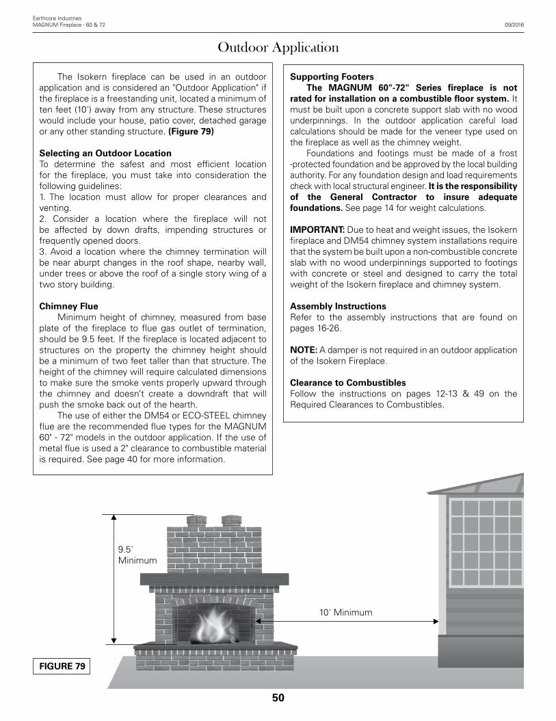
50
Earthcore IndustriesMAGNUM Fireplace - 60 & 72 09/2016
Outdoor Application
The Isokern fireplace can be used in an outdoor application and is considered an "Outdoor Application" if the fireplace is a freestanding unit, located a minimum of ten feet (10') away from any structure. These structures would include your house, patio cover, detached garage or any other standing structure. (Figure 79)
Selecting an Outdoor LocationTo determine the safest and most efficient location for the fireplace, you must take into consideration the following guidelines:1. The location must allow for proper clearances and venting.2. Consider a location where the fireplace will not be affected by down drafts, impending structures or frequently opened doors. 3. Avoid a location where the chimney termination will be near aburpt changes in the roof shape, nearby wall, under trees or above the roof of a single story wing of a two story building.
Chimney Flue Minimum height of chimney, measured from base plate of the fireplace to flue gas outlet of termination, should be 9.5 feet. If the fireplace is located adjacent to structures on the property the chimney height should be a minimum of two feet taller than that structure. The height of the chimney will require calculated dimensions to make sure the smoke vents properly upward through the chimney and doesn’t create a downdraft that will push the smoke back out of the hearth. The use of either the DM54 or ECO-STEEL chimney flue are the recommended flue types for the MAGNUM 60" - 72" models in the outdoor application. If the use of metal flue is used a 2" clearance to combustible material is required. See page 40 for more information.
Supporting Footers The MAGNUM 60"-72" Series fireplace is not rated for installation on a combustible floor system. It must be built upon a concrete support slab with no wood underpinnings. In the outdoor application careful load calculations should be made for the veneer type used on the fireplace as well as the chimney weight. Foundations and footings must be made of a frost -protected foundation and be approved by the local building authority. For any foundation design and load requirements check with local structural engineer. It is the responsibility of the General Contractor to insure adequate foundations. See page 14 for weight calculations.
IMPORTANT: Due to heat and weight issues, the Isokern fireplace and DM54 chimney system installations require that the system be built upon a non-combustible concrete slab with no wood underpinnings supported to footings with concrete or steel and designed to carry the total weight of the Isokern fireplace and chimney system.
Assembly InstructionsRefer to the assembly instructions that are found on pages 16-26.
NOTE: A damper is not required in an outdoor application of the Isokern Fireplace.
Clearance to CombustiblesFollow the instructions on pages 12-13 & 49 on the Required Clearances to Combustibles.
10' Minimum
9.5' Minimum
FIGURE 79

51
Earthcore Industries06/2016 MAGNUM Fireplace - 60 & 72
1. Chimney Installation and Drafting Metal chimney systems will only draft properly when they are installed according to the instructions, in an appropriate location and with the proper chimney height. Installing the fireplace according to the instructions, choosing an appropriate location, and choosing an appropriate chimney height are the responsibility of the designer and the building contractor. Tightly insulated and sealed homes, two story interior spaces and high vaulted ceilings can cause negative air pressures within the house which can impair drafting performance. HVAC return air ducts near the fireplace opening will adversely affect the fireplace drafting performance. It is the responsibility of the designer, the building contractor and their mechanical contractor to determine that the building’s internal air pressures are conducive to positive fireplace drafting. Avoid placing any fireplace in an area near tall trees, tall buildings, or high land masses. These structures can reduce ambient air flow pressure as well as produce down drafts, either of which can impair fireplace drafting performance. Earthcore Industries L.L.C. does not warrant drafting and is not responsible for it.
2. Fireplace Curing Instructions It is critical that the Isokern masonry elements in thefirebox and smoke dome assembly be dry before firing of the unit. Moisture left in the components from exposure during storage and shipping, as well as moisture from the installation phase, must be eliminated before the unit is put to its intended use. The first step in reducing the ambient moisture is to be sure that the completed fireplace rest totally in a dried-in setting for a minimum of 28 days after construction of the unit is complete. The next step in curing the fireplace is to be sure that the first five or six fires are of short duration. The first fire of the unit can take place once the minimum twenty-eight day drying period has passed. This fire should be especially short. Start the first fire slowly with a small amount of paper and kindling (small dry wood splits or twigs) and a maximum load of four to six pounds of dry firewood, estimated to be no more than two or three logs each of about three inches (3”) to four inches (4”) diameter. The first fire should burn for no more than thirty to sixty minutes and then allowed to go out. Do not refuel the fireplace during the first lighting. A cooling off period of twenty-four hours, at a minimum, should follow the first fire. The second fire should be the same as the first fire. It should burn for no more than thirty to sixty minutes and allowed to go out. Do not refuel the fireplace during
51
Summary
the second lighting. A twenty-four hour cooling off period must be observed following second lighting. After first and second fire, continue use of the unit with three or four small fires of short duration (sixty minutes or so) and small fuel load. After these first five or six small fires of short duration normal use of the fireplace can proceed. For normal use the maximum recommended fuel load is twelve to sixteen pounds of dry firewood at a time. This fuel load is considered to be approximately three to five cured hardwood logs of about three inches (3”) to six inches (6”) in diameter. As the fire burns down, refueling should be only one or two logs added at a time.
IMPORTANT: Do not burn construction debris or trash of any kind in the fireplace. Whereas it is not uncommon for construction debris and refuse to be burned in a fireplace by site personnel on a project that is under construction, this activity must be avoided. It is the responsibility of the building contractor to insure that the required dry-in period is met and that the required lighting sequence is performed by the owner or by the owner’s agent.
3. Log Grates Log grates are required for burning solid fuel in the Isokern fireplace. Grates allow for easy air flow up through the burning logs thus creating a more complete and efficient burning of the fuel.
4. How to Build a Fire First set the fireplace damper in the full open position. Begin laying the fire by placing several pieces of wadded up paper directly on the log grate. Place kindling (small splits of dry pine or other dry softwood) on top of the paper, enough to loosely cover the paper. Next arrange several small, dry hardwood or softwood logs or log splits on top of the kindling layer. Finally, arrange two or three larger hardwood logs (oak, hickory, etc.) or log splits on top of the stack.Ignite the paper at the bottom of the stack. The burning paper will ignite the kindling which will, in turn, set the remaining fuel on fire. Be sure to stack all firewood in such a way that it will settle into the log grate as the paper and kindling layers are burned away. Additional logs can be set onto the fire as each fueling burns down. Ideally, fuel logs should be of a hardwood species that have been air dried for one year or longer. Use of cured or uncured pine logs and uncured hardwood logs for fuel should be avoided. Pine logs and uncured hardwood logs will tend to smolder and burn at relatively low temperatures producing high levels of soot and creosote.

52
Earthcore IndustriesMAGNUM Fireplace - 60 & 72 09/2016
52
IMPORTANT: Do not throw, toss, jam, kick or otherwise force logs into the Isokern fireplace.
WARNING: Never use gasoline, gasoline type lantern fuel, kerosene, charcoal lighter fluid or other similar liquids to start or “freshen up” the fire in this fireplace or in any fireplace.
WARNING: If processed solid fuel fire logs are used: Do not poke or stir the logs while they are burning. Use only fire logs that have been evaluated for the application in fireplace and refer to fire log warnings and caution markings on packaging prior to use.
5. Avoid Over-firing this FireplaceSome examples of over-firing are: a. Burning of scrap lumber, construction debris, pine branches and brush or cardboard boxes; b. Burning small diameter twigs, branches or any other small sized combustible materials in quantities which exceed the volume of the normal log fire; c. Use of artificial wax base logs, trash or other chemicals or chemically treated combustibles.
WARNING: Over-firing can permanently damage this fireplace system.
6. Fireplace Doors and Screens The following door manufacturers are approved for installation and use on all Isokern gas fireplaces. We require an outside air kit be installed into the fireplace with a minimum duct size of 4” to provide an adequate make up air supply. See page 19 for Outside Air Kit guidelines. All glass must be a minimum of 3/16” in thickness and shall be of tempered or ceramic glass as supplied by our approved vendors. DOORS MUST BE KEPT IN THE OPEN POSITION WHEN FIREPLACE IS IN USE.
Approved vendors:Design Specialties11100 W Heather AveMilwaukee, WI 53224414-371-1200
Ironhaus Inc113 Lewis Lane Hamilton, MT 59840406-961-1800
Stoll Fireplace153 Hwy 201Abbeville, SC 29620800-421-0771
Summary
7. Disposal of Ashes It is recommended that the firebox be cleaned of excessive ashes before each use. It is necessary to remove ashes from the open front of the fireplace. To do so, proceed in the following manner: Allow the fire to go out and the ashes to cool for at least six to eight hours. After the cooling period carefully pick up the ashes from the firebox with a small, metal fireplace shovel or other metal scoop and place them in a metal container with a tight fitting lid. If possible do not sweep the ashes as this will stir them into the air and disperse them into the room. The closed container of ashes should be placed on a non-combustible floor or on the ground, well away from all combustible materials, pending final disposal. If the ashes are disposed of by burial in soil or otherwise locally dispersed, they should be retained in the closed container until all cinders have thoroughly cooled.
8. Gas Log Sets If you install a vented gas log set (decorative gas appliance), the log set must comply with the Standard for Decorative Gas Appliance for Installation in Solid Fuel Burning Fireplaces, ANSI Z21.60 or Z21.84 and shall also be installed in accordance with the National Fuel Gas Code, ANSI 7223NFPA 54 latest edition. If you wish to install an unvented (vent-free) gas log set, only unvented gas log sets which have been found to comply with the standard for unvented room heaters, ANSI Z21.11.2 are to be installed in this fireplace. Check local codes for complaince for unvented (vent free) gas log sets.
WARNING: Do not operate a vented gas log set in this fireplace with the chimney removed.
9. Log Lighter If a log lighter is installed, it should be installed on the front of the grate in such a manner to minimize flame impingement, the amount of heat exposure and that logs placed on the grate will not rest directly on the log lighter tube. Also, the floor clearance should be sufficient to minimize the chance of the blockage of the burner ports by ash accumulation. Installation of the log lighter should follow all local codes or, in the absence of local codes, to the National Fuel Gas Code, ANSI Z 223. 1INFPA 54. Refer to log lighter manufacturer for installation instructions, clearances and any information specific to that log lighter system.

53
Earthcore Industries09/2016 MAGNUM Fireplace - 60 & 72
8. Inspection and Cleaning At least twice a year in warm climates or monthly during the heating season in colder climates, thoroughly inspect the fireplace and chimney system. Chimneys must be installed so that access is provided for inspection and cleaning. The chimney should be inspected monthly during the heating season. Inspect the entire flue from the top down for obstructions such as birds’ nests, leaves, etc. Such obstructions must be removed. Check spark arrestor screens for clear flow of smoke every two to four weeks during the heating season. Inspect the flue periodically during the heating season for the presence of soot and creosote build up. If creosote or soot has accumulated, it should be removed to reduce the risk of chimney fire. Have your chimney cleaned and inspected by a professional chimney sweep annually.
WARNING: Do not use chemical fireplace and chimney cleaners that are poured on a hot fire. These can be dangerous and generally work only on the flue section nearest the fire, leaving the rest of the flue unaffected.
9. Exterior Maintenance Annually, at a minimum, check all metal flashings and weather seals around the exterior chimney where it penetrates the roof surface; inspect any chimney top spark arrestors, metal cowlings and weather hoods to make sure they are secure and weather tight. Seal any cracks or gaps in chimney-to-roof flashings to prevent possible roof and chimney chase leaks. Inspect any cement chimney cap or clay chimney pot terminations to make sure they are not diverting water into the structure. Seal any suspected cracks or gaps in these masonry components.
53
Summary

_________________________________________
_________________________________________
_________________________________________
_________________________________________
_________________________________________
_________________________________________
_________________________________________
_________________________________________
_________________________________________
_________________________________________
_________________________________________
_________________________________________
_________________________________________
_________________________________________
_________________________________________
_________________________________________
_________________________________________
_________________________________________
_________________________________________
_________________________________________
_________________________________________
_________________________________________
_________________________________________
_________________________________________
54
Earthcore IndustriesMAGNUM Fireplace - 60 & 72 09/2016
_________________________________________
_________________________________________
_________________________________________
_________________________________________
_________________________________________
_________________________________________
_________________________________________
_________________________________________
_________________________________________
_________________________________________
_________________________________________
_________________________________________
_________________________________________
_________________________________________
_________________________________________
_________________________________________
_________________________________________
_________________________________________
_________________________________________
_________________________________________
_________________________________________
_________________________________________
_________________________________________
_________________________________________
54
Notes

55
Earthcore Industries09/2016 MAGNUM Fireplace - 60 & 72
Registration Card
Please tear out along dashed lines and send to:
Earthcore IndustriesAttn: Technical Department6899 Phillips Industrial BlvdJacksonville, FL 32256
Dealer _______________________________________________________________________________________________
Date of Purchase: _____________________________ Date Of Installation: _____________________________________
Address: _____________________________________________________________________________________________
City, State, Zip: _______________________________________________________________________________________
Phone No.: ___________________________________
Fireplace Size (Circle One): MAGNUM 60” (82060) MAGNUM 72” (82072)
Fuel Type (Circle One): Solid Wood Natural Gas Propane
Fireplace Serial Number: _______________________________________________________________________________
(Located on Rating Plate Inside Fireplace)
Buyer: _______________________________________________________________________________________________
Address: _____________________________________________________________________________________________
City, State, Zip: _______________________________________________________________________________________
Phone No.: ___________________________________
Installed By: __________________________________________________________________________________________
Address: _____________________________________________________________________________________________
City, State, Zip: _______________________________________________________________________________________
Phone No.: ___________________________________

6899 Phillips Industrial Blvd. • Jacksonville, FL 32256 • 904.363.3417 • f: 904.363.3408 • earthcore.co
Warranty & DisclaimerIsokern MAGNUM Series Fireplace
ISOKERN offers a lifetime warranty for all Isokern components, to be free from defects in materials that negatively affect system performance from the date of purchase, subject to the terms and conditions of this limited warranty.
This warranty covers only the above stated components, and NO WARRANTY, EXPRESS OR IMPLIED, EXTENDS TO ANY OF THE HARDWARE, FOOTING, VENTS, DUCTING, metal flues, FIREBRICK OR ACCESSORIES. THIS WARRANTY DOES NOT COVER DRAFTING, SMOKING OR PUFFING OF THE FIREPLACE SYSTEM. Factors beyond the manufacturer's control affect fireplace drafting, smoking, and puffing, and ISOKERN cannot guarantee these aspects of performance.
If a component is found to be defective under the terms of this warranty the party to whom this warranty is extended shall, notify ISOKERN, 6899 Philips Industrial Blvd, Jacksonville, Florida 32256, in writing, by registered mail, within thirty (30) days following the discovery of the defect within the lifetime warranty period. The notice shall contain (1) the date of purchase; (2) place of purchase; (3) address of installation; (4) name, address and phone number of the owner; and (5) a brief description of the defect.
ISOKERN, or any division thereof, is not responsible for any labor costs or indirect costs incurred for the replacement of defective components.
ISOKERN is not responsible for misuse or mishandling of components. Nothing in this warranty makes ISOKERN, or any division thereof, liable in any respect for any injury or damage to the building or structure in which the fireplace or chimney system has been installed or to persons or property therein arising out of the use, misuse, or installation of properly manufactured ISOKERN product.
ISOKERN, OR ANY DIVISION THEREOF, SHALL NOT BE HELD LIABLE FOR ANY INCIDENTAL OR CONSEQUENTIAL DAMAGES OR EXPENSES ARISING OUT OF THE USE OF THE FIREPLACES OR CHIMNEY SYSTEMS. ALL SUCH DAMAGES AND EXPENSES ARE HEREBY EXCLUDED.
This warranty is null and void when the fireplace or chimney systems are not installed pursuant to the installation instructions provided by ISOKERN or local building codes have not been followed completely.
This warranty applies only to those fireplace and chimney systems installed in the continental United States, Alaska, and Canada. If any part of this warranty is found to be unenforceable, the remaining parts shall remain in force and effect.
ISOKERN HEREBY DISCLAIMS ALL GUARANTEES AND WARRANTIES, EXPRESS OR IMPLIED, BEYOND THE WARRANTIES SET FORTH HEREIN.
TECH1000_0916