Embed Size (px)
Citation preview
ISO 9001 : 2000 CERTIFIEDBY AFAQ No. QUAL / 1997 / 7034 a
Quality • Reliability • Innovation
COPPER TELECOMMUNICATION CABLES

COPPERTELECOMMUNICATION CABLES
NOTICE
INTRODUCTION
QUALITY ASSURANCE
RECOMMENDED ORDERING PARAMETERS
OUR TYPE AND CODE DESIGNATION
DUCT, UNDERGROUND NETWORK CABLES USED IN FEEDER AND DISTRIBUTION
6.1 - PE insulated, Petroleum jelly filled, PE sheathed
6.2 - PE insulated, PE sheathed
DIRECT BURIAL, UNDERGROUND NETWORK CABLESUSED IN FEEDER AND DISTRIBUTION
7.1 - PE insulated, Petroleum jelly filled, double steel tape armoured, PE sheathed
7.2 - PE insulated, double steel tape armoured, PE sheathed
FIGURE 8 AERIAL NETWORK CABLES USED IN DISTRIBUTION
8.1 - PE insulated, Petroleum jelly filled, PE sheathed, with steelmessenger
8.2 - PE insulated, PE sheathed, with steel messenger
8.3 - PE insulated, Petroleum jelly filled, double steel tape armoured,PE sheathed, with steel messenger
8.4 - PE insulated, double steel tape armoured, PE sheathed, with steelmessenger
INDOOR USE TELEPHONE CABLES, PVC INSULATEDAND PVC SHEATHED
JUMPER WIRE
DROP WIRE
ANNEX A - INDENTIFICATION OF CONDUCTORS AND UNITSAND CABLE CORE CONSTRUCTION OFUNDERGROUND AND AERIAL NETWORK CABLES
ANNEX B - IDENTIFICATION OF CONDUCTORS OFINDOOR USE TELEPHONE CABLE - LIBTEL
P a g e
1
2
3
3
4
6
6
9
1 2
1 2
1 5
1 8
1 8
2 1
2 4
2 7
3 0
3 2
3 3
3 4
3 6
1
2
3
4
5
6
7
8
9
10
11
CONTENTS

1
As this catalogue is not intended to cover all of LIBAN CABLES S A L possibilities inCopper Telephone Cables manufacturing, the hereafter listing of the types of cables is notrestrictive but only indicative of the main and most current types we manufacture.
On the other hand, our specification sheets are inspired mainly from InternationalElectrotechnical Commission Specifications (IEC) only in order to conform with thesustained trend, noticed both regionally and worldwide, towards these same IECsupposed to inspire any further standardization approaches.
That is why, while consulting this brochure, it is important to keep in mind that:- any combination or change of the constructional details mentioned in hereafter
chapter 5 remains feasible, on base of special conception development, matchingany special or different specifications,
- we can offer additional possibilities and alternatives like for example:- Pair, quad, and other basic formations- Unit or concentric stranding- Comparted construction (ex: MIC cables)
- our production encompasses all telecom cables of low, high or special mutualcapacitance and conductor gauges ≥ 0.4 mm.
F i n a l l y, and within our policy of constant improvement, we reserve the right to alter anypart of the information contained in this publication without incurring any obligation. Inall cases this brochure being only indicatve, and unless expressly agreed upon, it cannotbe considered by any mean as contractual document.
1 NOTICE
Devoted to the manufacturing of electric and telecomcables, Liban Cables is the first and largest supplier inLebanon and a leader in the Middle-East region.
Liban Cables was founded in 1967 by a group ofLebanese industrialists backed up by the technicalassistance of two international leading firms :
- Les Cables de Lyon - France (became A L C AT E L afterwards
and NEXANS by end 2000)
- Phelps Dodge - U.S.A.
S t a ffed with qualified engineers and highly skilledtechnicians, our plant is located in Nahr-Ibrahim at 30Km from Beirut, where cables are designed andmanufactured according to all internationalspecifications : IEC, VDE, UTE, BS and others oncustomer request.
Early after its foundation, Liban Cables has become themajor supplier of the Lebanese market in both the publicand private sectors. The product range of Liban Cablescovers all Copper and Aluminium electric cables, aswell as copper and fiber optic communication cables, inaddition to a wide variety of special cablesmanufactured on customer request.
High quality cables, continuous developments of theproduction range, direct and fast shipments havecontributed in rendering Liban Cables an importantexporter for many countries on the three limitrophecontinents (Asia, Europe, Africa). Liban Cablesproducts are particularly appreciated by administrationsand international contractors operating in the region andseeking reliable and direct supplies of power andcommunication cables.
2 INTRODUCTION
2

3
Step by step, from raw material to final product, quality constitutes a major concern toLiban Cables.
Raw material are continuously and repetitively tested from trial orders till the last batchreceived afterwards.
Products are tested within two simultaneous procedures :
- A built in quality control system carried out by the production itself at any step of workin process.
- A parallel and contradictory procedure is also carried out on the same stages andproducts by independent inspectors reporting to the quality control service.
End users and/or third part inspection authorities are also constantly commissioning thefinished products and assessing the strict conformity to ordered specifications.
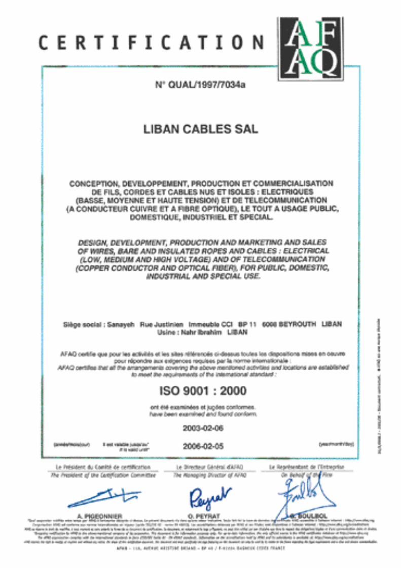
In fact, our ISO 9001 certification stated in Feb 1997 by the International CertificationNetwork (EQNET) is certified by the French Association for Quality Assurance (AFAQ),the well known rigourous and independant accredited European assessor. T h i scertification, which upgraded to ISO 9001:2000 on February 2003, under referenceA FAQ Nº QUAL / 1997 / 7034 a, confirms the soundness and the performance of theQuality System we apply for the Design, the Development, the Manufacturing and theMarketing & Sales of all our products.
For prompt quotation / supplies, please make sure your inquiries and your orders aresecuring the following data :
1 - International or Special Standard. (Alternatively, the precise usage of the cable.)
2 - Constructional details (Materials, Pairs / Quads, Mutual Capacitance, Filling,
Screens, Armour, Messenger ...etc).
3 - Other requirements
4 - Packing & Tolerances
5 - Required delivery time
6 - Required validity
3 QUALITY
4 RECOMMENDED ORDERING PARAMETERS

No letter - PE sheathY - PVC sheathU - Halogen free, Low smoke and fume sheath
L - Lead sheathB - Black steel tape armouringG - Galvanized steel tape armouringR - Galvanized round steel wire armouringF - Flat steel wire armouringA- Aluminium tape armouringW - Round aluminium wire armouringZ - One side coated corrugated steel tapeK - Two side coated corrugated steel tape
S - One side coated aluminium screenD - Two side coated aluminium screenI - Two side coated corrugated aluminium screenZ - Non coated aluminium screenO - Copper tape screenH - Corrugated copper tape screenC - Copper wire screenQ - Lacquered aluminium screen
P - Solid PE insulationC - Cellular PE insulationM - (Foam / skin) PE insulationY - PVC insulation
2 - For cables stranded in pairs4 - For cables stranded in star quads
The type designation is a combination of symbols (letters and numbers) indicating thetype, and the main constructional elements of the cable as follows :
OUTDOOR CABLES
5 OUR TYPE AND CODE DESIGNATION
1
T-Telephone cables
A- Aerial CablesU - Underground / Armoured CablesD - Underground / Duct Cables
2 3 4 5 6 7
4
5
Example:TU2MDG - Telephone cable, underground, pair Type, foam / skin PE insulated, two side
coated Aluminium screened, galvanized steel tape armoured.
N . B . : The sequence of the 3rd and 4th characters indicates whether the cable is jellyfilled or not. For jelly filled cables, these two characters are interchanged, i.e. theletter indicating the type of insulation (P,C,M or T) comes before the numberindicating the type of stranding (2 or 4).
Examples :TUM2DG - Telephone cable, underground, foam / skin PE insulated, pair Type, jelly
filled, two side coated Aluminium screened, galvanized steel tape armoured.TU2MDG - Same cable but not jelly filled.
INDOOR CABLES
LIBTEL for unscreened PVC insulated and sheathed cables
LIBTLV for tinned copper conductor, PVC insulated and sheathed cables
LIBTLS for screened, PVC insulated and sheathed cables
LIBTLA for armoured, PVC insulated and sheathed cables

6
ConductorsSolid annealed bare copper wire of:0.4 - 0.5 - 0.6 or 0.8 mm nominal diameter.Other wire diameters are also available.InsulationOne layer of fully coloured solidpolyethylene, or one layer of colourlesscellular polyethylene covered by a thinlayer of fully coloured solid polyethylene(foam-skin).Radial thickness determined to satisfythe electrical characteristics.Twisting2 conductors are twisted into a pair.D i fferent twisting laylengths are used tominimize crosstalk.Quad cables are available upon request.StrandingIn sub-units of 10 pairs, for units of 50 or100 pairs and for cables of up to 100 pairs.In units of 50 or 100 pairs for cables ofmore than 100 pairs.Other repartition also available.Spare pairsLocated within the units or between theunits of the outer layer of the cable core,they are used to replace the pairs damagedduring the manufacturing process.Cable core construction, identification ofconductors and units: see annex A.Longitudinal watertightnessThe cable core interstices are filled with asuitable compound (petroleum jelly) toavoid longitudinal water penetrationinside the cable.Cable core protectionOne or more tapes helically orlongitudinally laid with an overlap.Continuity wire (when specified)One 0.5 mm diameter tinned copper wireis longitudinally laid to ensure theelectrical continuity of the screen.
CONSTRUCTION
Moisture barrierand screenOne or two side ethylene copolymerecoated smooth aluminium tape islongitudinally laid with an overlap.Nominal thickness of aluminium : 0.15 mm.D i fferent or corrugated screen alsoavailable.
SheathBlack, high, medium or low densitypolyethylene.Nominal radial thickness: as requested oras per the physical characteristics table.
Marking• manufacturer’s identification• number of pairs and conductor diameter• sequentially numbered length markingat each meter interval (or as requested).
DUCTUNDERGROUND NETWORK CABLEUSED IN FEEDER AND DISTRIBUTION ( FILLED )
6
6.1 polyethylene insulated
longitudinally watertight
polyethylene sheathed
Specification:Based on IEC 60708-1 and 60708-2
Type and ApplicationOur type TDM2DPulling in duct

7
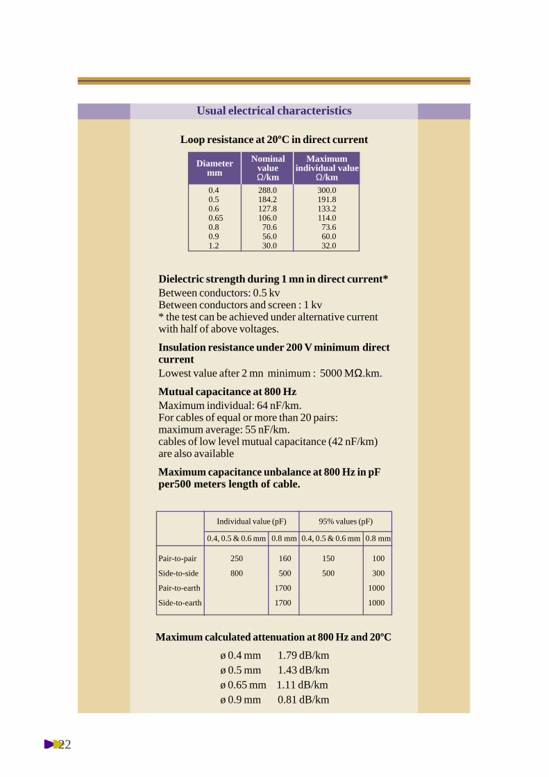
Loop resistance at 20ºC in direct current
Diametermm
NominalvalueΩ/km
Maximumindividual value
Ω/km0.40.50.60.650.80.91.2
288.0184.2127.8106.070.656.030.0
300.0191.8133.2114.073.660.032.0
Dielectric strength during 1 mn in direct current*Between conductors: 0.5 kvBetween conductors and screen : 1 kv* the test can be achieved under alternative currentwith half of above voltages.
Insulation resistance under 200 V minimum directcurrentLowest value after 2 mn minimum : 5000 MΩ.km.
Mutual capacitance at 800 HzMaximum individual: 64 nF/km.For cables of equal or more than 20 pairs:maximum average: 55 nF/km.cables of low level mutual capacitance (42 nF/km)are also available
Maximum capacitance unbalance at 800 Hz in pFper500 meters length of cable.
Maximum calculated attenuation at 800 Hz and 20ºC
ø 0.4 mm 1.79 dB/kmø 0.5 mm 1.43 dB/kmø 0.6 mm 1.19 dB/kmø 0.8 mm 0.90 dB/km
Usual electrical characteristics
Pair-to-pair
Side-to-side
Pair-to-earth
Side-to-earth
250
800
160
500
1700
1700
150
500
100
300
1000
1000
0.8 mm0.4, 0.5 & 0.6 mm0.8 mm0.4, 0.5 & 0.6 mm
Individual value (pF) 95% values (pF)
8
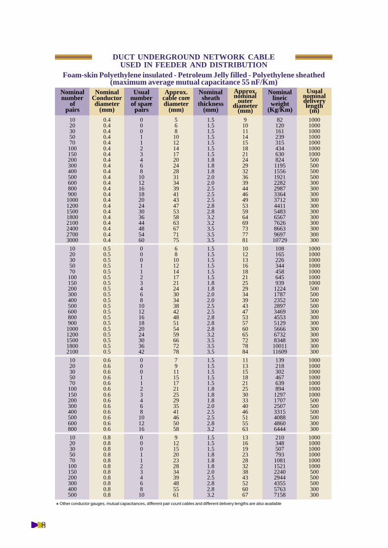
DUCT UNDERGROUND NETWORK CABLEUSED IN FEEDER AND DISTRIBUTION
Foam-skin Polyethylene insulated - Petroleum Jelly filled - Polyethylene sheathed(maximum average mutual capacitance 55 nF/Km)
102030507010015020030040050060080090010001200150018002100240027003000
102030507010015020030040050060080090010001200150018002100
1020305070100150200300400500600800
1020305070100150200300400500
0.40.40.40.40.40.40.40.40.40.40.40.40.40.40.40.40.40.40.40.40.40.4
0.50.50.50.50.50.50.50.50.50.50.50.50.50.50.50.50.50.50.5
0.60.60.60.60.60.60.60.60.60.60.60.60.6
0.80.80.80.80.80.80.80.80.80.80.8
0001123468101216182024303644485460
0001123468101216182024303642
0001123468101216
000112346810
56810121417202428313439414347535863677175
681012141721243034384248515459667278
791115172125293541465058
912152023283439485561
1.51.51.51.51.51.51.51.81.81.82.02.02.52.52.52.82.83.23.23.53.53.5
1.51.51.51.51.51.51.81.82.02.02.52.52.82.82.83.23.53.53.5
1.51.51.51.51.51.81.81.82.02.52.52.83.2
1.51.51.51.81.81.82.02.52.82.83.2
9101114151821242932363944464953596469737781
10121316182125293439434753576065727884
11131518212530334046515563
1316192328323843526067
82120161239315434630824119515561921228229873364371244115483656776268663969710729
10816522634445864593912241787235228973469455351295666673283481001111609
1392183024676398941297170725073315408848606444
2103485077931081152122402944435557637158
1000100010001000100010001000500500500500300300300300300300300300300300300
1000100010001000100010001000500500500500300300300300300300300300
1000100010001000100010001000500500500500300300
100010001000100010001000500500500300300
Nominalnumber
ofpairs
NominalConductordiameter
(mm)
Usualnumberof spare
pairs
Usualnominaldeliverylength
(m)
Approx.cable corediameter
(mm)
Nominalsheath
thickness(mm)
Approx.nominal
outerdiameter
(mm)
Nominallineic
weight(Kg/Km)
* Other conductor gauges, mutual capacitances, different pair count cables and different delivery lengths are also available
9
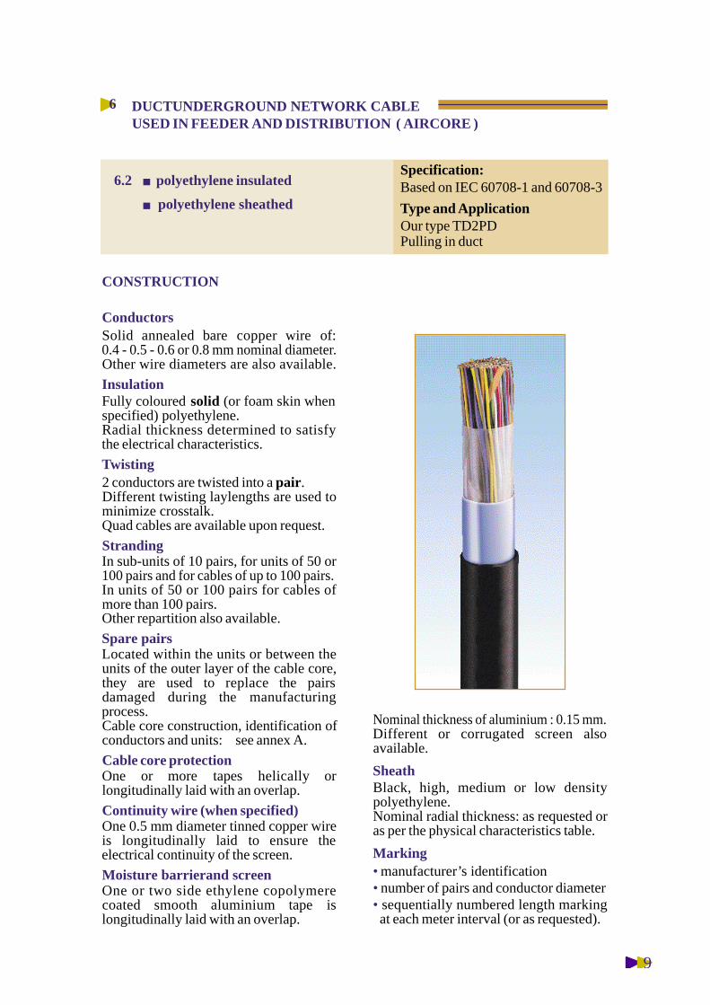
ConductorsSolid annealed bare copper wire of:0.4 - 0.5 - 0.6 or 0.8 mm nominal diameter.Other wire diameters are also available.
InsulationFully coloured s o l i d (or foam skin whenspecified) polyethylene.Radial thickness determined to satisfythe electrical characteristics.
Twisting2 conductors are twisted into a pair.D i fferent twisting laylengths are used tominimize crosstalk.Quad cables are available upon request.
StrandingIn sub-units of 10 pairs, for units of 50 or100 pairs and for cables of up to 100 pairs.In units of 50 or 100 pairs for cables ofmore than 100 pairs.Other repartition also available.
Spare pairsLocated within the units or between theunits of the outer layer of the cable core,they are used to replace the pairsdamaged during the manufacturingprocess.Cable core construction, identification ofconductors and units: see annex A.
Cable core protectionOne or more tapes helically orlongitudinally laid with an overlap.
Continuity wire (when specified)One 0.5 mm diameter tinned copper wireis longitudinally laid to ensure theelectrical continuity of the screen.
Moisture barrierand screenOne or two side ethylene copolymerecoated smooth aluminium tape islongitudinally laid with an overlap.
CONSTRUCTION
Nominal thickness of aluminium : 0.15 mm.D i fferent or corrugated screen alsoavailable.
SheathBlack, high, medium or low densitypolyethylene.Nominal radial thickness: as requested oras per the physical characteristics table.
Marking• manufacturer’s identification• number of pairs and conductor diameter• sequentially numbered length markingat each meter interval (or as requested).
DUCTUNDERGROUND NETWORK CABLEUSED IN FEEDER AND DISTRIBUTION ( AIRCORE )
6
Specification:Based on IEC 60708-1 and 60708-3
Type and ApplicationOur type TD2PDPulling in duct
6.2 polyethylene insulated
polyethylene sheathed

10
Loop resistance at 20ºC in direct current
Diametermm
NominalvalueΩ/km
Maximumindividual value
Ω/km0.40.50.60.650.80.91.2
288.0184.2127.8106.070.656.030.0
300.0191.8133.2114.073.660.032.0
Dielectric strength during 1 mn in direct current*Between conductors: 1 kvBetween conductors and screen : 3 kv* the test can be achieved under alternative currentwith half of above voltages.
Insulation resistance under 200 V minimum directcurrentLowest value after 2 mn minimum : 5000 MΩ.km.
Mutual capacitance at 800 HzMaximum individual: 64 nF/km.For cables of equal or more than 20 pairs:maximum average: 55 nF/km.cables of low level mutual capacitance (42 nF/km)are also available
Maximum capacitance unbalance at 800 Hz in pFper500 meters length of cable.
Maximum calculated attenuation at 800 Hz and 20ºC
ø 0.4 mm 1.79 dB/kmø 0.5 mm 1.43 dB/kmø 0.6 mm 1.19 dB/kmø 0.8 mm 0.90 dB/km
Usual electrical characteristics
Pair-to-pair
Side-to-side
Pair-to-earth
Side-to-earth
250
800
160
500
1700
1700
150
500
100
300
1000
1000
0.8 mm0.4, 0.5 & 0.6 mm0.8 mm0.4, 0.5 & 0.6 mm
Individual value (pF) 95% values (pF)
11
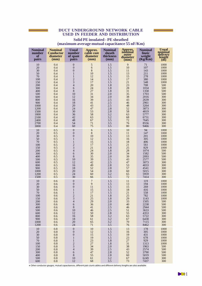
DUCT UNDERGROUND NETWORK CABLEUSED IN FEEDER AND DISTRIBUTION
Solid PE insulated - PE sheathed(maximum average mutual capacitance 55 nF/Km)
1020305070
100150200300400500600800900
10001200150018002100240027003000
1020305070
100150200300400500600800900100012001500
1020305070
100150200300400500600800900
10001200
1020305070
100150200300400500600
0.40.40.40.40.40.40.40.40.40.40.40.40.40.40.40.40.40.40.40.40.40.40.50.50.50.50.50.50.50.50.50.50.50.50.50.50.50.50.50.60.60.60.60.60.60.60.60.60.60.60.60.60.60.60.60.80.80.80.80.80.80.80.80.80.80.80.8
0001123468101216182024303642485460000112346810121618202430000112346810121618202400011234681012
5681012141720242731343941434753586367717568101215172124303539424952546066791115172125293641465058616571101215192327343947556168
1.51.51.51.51.51.51.51.81.81.82.02.02.52.52.52.82.83.23.23.53.53.51.51.51.51.51.51.51.81.82.02.02.52.52.82.82.83.23.51.51.51.51.51.51.81.82.02.02.52.52.83.23.23.23.51.51.51.51.51.81.82.02.52.82.83.23.5
9101113151721232831353843464852586368727680101113161821252834394347535760657211131518212529334046515563677076131619232731384352606773
7110714321127838054870810341358170320162639296132643873481957776731764585569466
9414720130540656182910741582209325773073403345415015595974141191942694165587821143150522382944363343535722643871158462178305431678929
1313196325743790501962497437
100010001000100010001000100050050050050030030030030030030030030030030030010001000100010001000100010005005005005003003003003003003001000100010001000100010001000500500500500300300300300300
100010001000100010001000500500500500300300
Nominalnumber
ofpairs
NominalConductordiameter
(mm)
Usualnumberof spare
pairs
Usualnominaldeliverylength
(m)
Approx.cable corediameter
(mm)
Nominalsheath
thickness(mm)
Approx.nominal
outerdiameter
(mm)
Nominallineic
weight(Kg/Km)
* Other conductor gauges, mutual capacitances, different pair count cables and different delivery lengths are also available
12
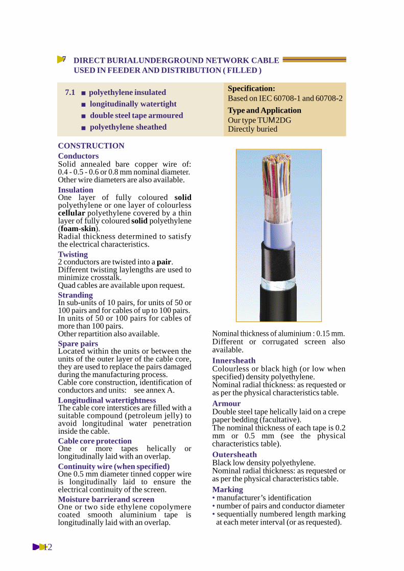
ConductorsSolid annealed bare copper wire of:0.4 - 0.5 - 0.6 or 0.8 mm nominal diameter.Other wire diameters are also available.InsulationOne layer of fully coloured s o l i dpolyethylene or one layer of colourlessc e l l u l a r polyethylene covered by a thinlayer of fully coloured solid polyethylene(foam-skin).Radial thickness determined to satisfythe electrical characteristics.Twisting2 conductors are twisted into a pair.D i fferent twisting laylengths are used tominimize crosstalk.Quad cables are available upon request.StrandingIn sub-units of 10 pairs, for units of 50 or100 pairs and for cables of up to 100 pairs.In units of 50 or 100 pairs for cables ofmore than 100 pairs.Other repartition also available.Spare pairsLocated within the units or between theunits of the outer layer of the cable core,they are used to replace the pairs damagedduring the manufacturing process.Cable core construction, identification ofconductors and units: see annex A.Longitudinal watertightnessThe cable core interstices are filled with asuitable compound (petroleum jelly) toavoid longitudinal water penetrationinside the cable.Cable core protectionOne or more tapes helically orlongitudinally laid with an overlap.Continuity wire (when specified)One 0.5 mm diameter tinned copper wireis longitudinally laid to ensure theelectrical continuity of the screen.Moisture barrierand screenOne or two side ethylene copolymerecoated smooth aluminium tape islongitudinally laid with an overlap.
CONSTRUCTION
Nominal thickness of aluminium : 0.15 mm.D i fferent or corrugated screen alsoavailable.InnersheathColourless or black high (or low whenspecified) density polyethylene.Nominal radial thickness: as requested oras per the physical characteristics table.ArmourDouble steel tape helically laid on a crepepaper bedding (facultative).The nominal thickness of each tape is 0.2mm or 0.5 mm (see the physicalcharacteristics table).OutersheathBlack low density polyethylene.Nominal radial thickness: as requested oras per the physical characteristics table.Marking• manufacturer’s identification• number of pairs and conductor diameter• sequentially numbered length markingat each meter interval (or as requested).
DIRECT BURIALUNDERGROUND NETWORK CABLEUSED IN FEEDER AND DISTRIBUTION ( FILLED )
7
Specification:Based on IEC 60708-1 and 60708-2
Type and ApplicationOur type TUΜ2DGDirectly buried
7.1 polyethylene insulatedlongitudinally watertightdouble steel tape armouredpolyethylene sheathed

13
Loop resistance at 20ºC in direct current
Diametermm
NominalvalueΩ/km
Maximumindividual value
Ω/km0.40.50.60.650.80.91.2
288.0184.2127.8106.070.656.030.0
300.0191.8133.2114.073.660.032.0
Dielectric strength during 1 mn in direct current*Between conductors: 0.5 kvBetween conductors and screen : 1 kv* the test can be achieved under alternative currentwith half of above voltages.
Insulation resistance under 200 V minimum directcurrentLowest value after 2 mn minimum : 5000 MΩ.km.
Mutual capacitance at 800 HzMaximum individual: 64 nF/km.For cables of equal or more than 20 pairs:maximum average: 55 nF/km.cables of low level mutual capacitance (42 nF/km)are also available
Maximum capacitance unbalance at 800 Hz in pFper500 meters length of cable.
Maximum calculated attenuation at 800 Hz and 20ºC
ø 0.4 mm 1.79 dB/kmø 0.5 mm 1.43 dB/kmø 0.6 mm 1.19 dB/kmø 0.8 mm 0.90 dB/km
Usual electrical characteristics
Pair-to-pair
Side-to-side
Pair-to-earth
Side-to-earth
250
800
160
500
1700
1700
150
500
100
300
1000
1000
0.8 mm0.4, 0.5 & 0.6 mm0.8 mm0.4, 0.5 & 0.6 mm
Individual value (pF) 95% values (pF)
14
102030507010015020030040050060080090010001200
10203050701001502003004005006008009001000
1020305070100150200300400500600800
1020305070100150200300400500
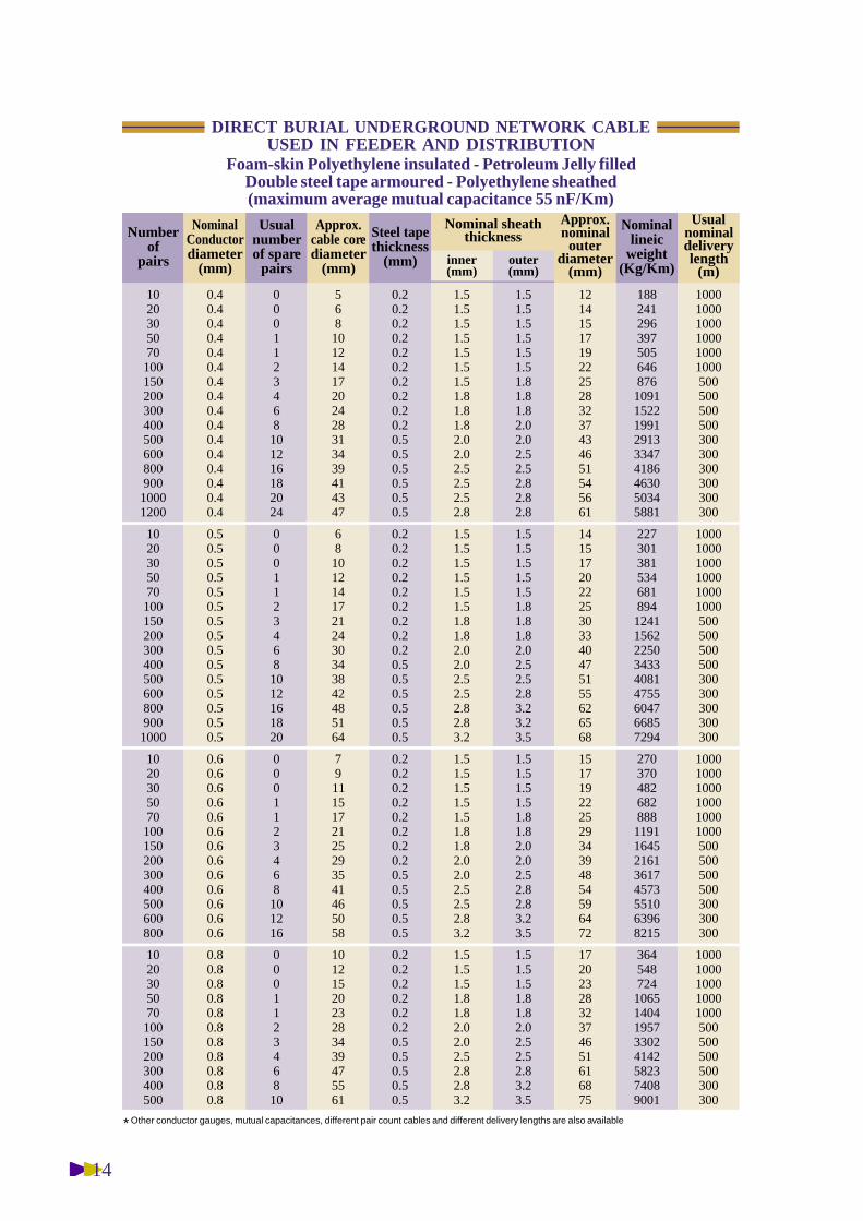
DIRECT BURIAL UNDERGROUND NETWORK CABLEUSED IN FEEDER AND DISTRIBUTION
Foam-skin Polyethylene insulated - Petroleum Jelly filledDouble steel tape armoured - Polyethylene sheathed(maximum average mutual capacitance 55 nF/Km)
Numberof
pairs
0.40.40.40.40.40.40.40.40.40.40.40.40.40.40.40.4
0.50.50.50.50.50.50.50.50.50.50.50.50.50.50.5
0.60.60.60.60.60.60.60.60.60.60.60.60.6
0.80.80.80.80.80.80.80.80.80.80.8
0001123468101216182024
00011234681012161820
0001123468101216
000112346810
56810121417202428313439414347
6810121417212430343842485164
791115172125293541465058
1012152023283439475561
0.20.20.20.20.20.20.20.20.20.20.50.50.50.50.50.5
0.20.20.20.20.20.20.20.20.20.50.50.50.50.50.5
0.20.20.20.20.20.20.20.20.50.50.50.50.5
0.20.20.20.20.20.20.50.50.50.50.5
1.51.51.51.51.51.51.51.81.81.82.02.02.52.52.52.8
1.51.51.51.51.51.51.81.82.02.02.52.52.82.83.2
1.51.51.51.51.51.81.82.02.02.52.52.83.2
1.51.51.51.81.82.02.02.52.82.83.2
1.51.51.51.51.51.51.81.81.82.02.02.52.52.82.82.8
1.51.51.51.51.51.81.81.82.02.52.52.83.23.23.5
1.51.51.51.51.81.82.02.02.52.82.83.23.5
1.51.51.51.81.82.02.52.52.83.23.5
12141517192225283237434651545661
141517202225303340475155626568
15171922252934394854596472
1720232832374651616875
188241296397505646876109115221991291333474186463050345881
227301381534681894124115622250343340814755604766857294
27037048268288811911645216136174573551063968215
36454872410651404195733024142582374089001
100010001000100010001000500500500500300300300300300300
100010001000100010001000500500500500300300300300300
100010001000100010001000500500500500300300300
10001000100010001000500500500500300300
NominalConductordiameter
(mm)
Usualnumberof spare
pairs
Steel tapethickness
(mm)
Approx.nominal
outerdiameter
(mm)
Usualnominaldeliverylength
(m)
Nominallineic
weight(Kg/Km)
Nominal sheaththickness
Approx.cable corediameter
(mm)inner(mm)
outer(mm)
* Other conductor gauges, mutual capacitances, different pair count cables and different delivery lengths are also available

15
ConductorsSolid annealed bare copper wire of:0.4 - 0.5 - 0.6 or 0.8 mm nominal diameter.Other wire diameters are also available.
InsulationFully coloured solid (or foam skin whenspecified) polyethylene.Radial thickness determined to satisfythe electrical characteristics.
Twisting2 conductors are twisted into a pair.D i fferent twisting laylengths are used tominimize crosstalk.Quad cables are available upon request.StrandingIn sub-units of 10 pairs, for units of 50 or100 pairs and for cables of up to 100 pairs.In units of 50 or 100 pairs for cables ofmore than 100 pairs.Other repartition also available.Spare pairsLocated within the units or between theunits of the outer layer of the cable core,they are used to replace the pairs damagedduring the manufacturing process.Cable core construction, identification ofconductors and units: see annex A.Cable core protectionOne or more tapes helically orlongitudinally laid with an overlap.Continuity wire (when specified)One 0.5 mm diameter tinned copper wireis longitudinally laid to ensure theelectrical continuity of the screen.Moisture barrierand screenOne or two side ethylene copolymerecoated smooth aluminium tape islongitudinally laid with an overlap.Nominal thickness of aluminium : 0.15 mm.Different or corrugated screen also available.Inner sheathColourless or black high (or low when
CONSTRUCTION
specified) density polyethylene.Nominal radial thickness: as requested oras per the physical characteristics table.ArmourDouble steel tape helically laid on a crepepaper bedding (facultative).The nominal thickness of each tape is 0.2mm or 0.5 mm (see the physicalcharacteristics table).Outer sheathBlack low density polyethylene.Nominal radial thickness: as requested oras per the physical characteristics table.
Marking• manufacturer’s identification• number of pairs and conductor diameter• sequentially numbered length markingat each meter interval (or as requested).
DIRECTBURIALUNDERGROUND NETWORK CABLEUSED IN FEEDER AND DISTRIBUTION ( AIRCORE )
7
Specification:Based on IEC 60708-1 and 60708-3
Type and ApplicationOur type TU2PDGDirectly buried
7.2 polyethylene insulated
double steel tape armoured
polyethylene sheathed

16
Loop resistance at 20ºC in direct current
Diametermm
NominalvalueΩ/km
Maximumindividual value
Ω/km0.40.50.60.650.80.91.2
288.0184.2127.8106.070.656.030.0
300.0191.8133.2114.073.660.032.0
Dielectric strength during 1 mn in direct current*Between conductors: 1 kvBetween conductors and screen : 3 kv* the test can be achieved under alternative currentwith half of above voltages.
Insulation resistance under 200 V minimum directcurrentLowest value after 2 mn minimum : 5000 MΩ.km.
Mutual capacitance at 800 HzMaximum individual: 64 nF/km.For cables of equal or more than 20 pairs:maximum average: 55 nF/km.cables of low level mutual capacitance (42 nF/km)are also available
Maximum capacitance unbalance at 800 Hz in pFper500 meters length of cable.
Maximum calculated attenuation at 800 Hz and 20ºC
ø 0.4 mm 1.79 dB/kmø 0.5 mm 1.43 dB/kmø 0.6 mm 1.19 dB/kmø 0.8 mm 0.90 dB/km
Usual electrical characteristics
Pair-to-pair
Side-to-side
Pair-to-earth
Side-to-earth
250
800
160
500
1700
1700
150
500
100
300
1000
1000
0.8 mm0.4, 0.5 & 0.6 mm0.8 mm0.4, 0.5 & 0.6 mm
Individual value (pF) 95% values (pF)

17
102030507010015020030040050060080090010001200
10203050701001502003004005006008009001000
1020305070100150200300400500600800
1020305070100150200300400500
DIRECT BURIAL UNDERGROUND NETWORK CABLEUSED IN FEEDER AND DISTRIBUTION
Solid Polyethylene insulated - Double steel tape armoured - Polyethylene sheathed(maximum average mutual capacitance 55 nF/Km)
Numberof
pairs
0.40.40.40.40.40.40.40.40.40.40.40.40.40.40.40.4
0.50.50.50.50.50.50.50.50.50.50.50.50.50.50.5
0.60.60.60.60.60.60.60.60.60.60.60.60.6
0.80.80.80.80.80.80.80.80.80.80.8
0001123468101216182024
00011234681012161820
0001123468101216
000112346810
56810121417192427313439414347
6810121417212430353942495254
791115172125293641465058
912151923273439475561
0.20.20.20.20.20.20.20.20.20.20.50.50.50.50.50.5
0.20.20.20.20.20.20.20.20.50.50.50.50.50.50.5
0.20.20.20.20.20.20.20.20.50.50.50.50.5
0.20.20.20.20.20.20.50.50.50.50.5
1.51.51.51.51.51.51.51.81.81.82.02.02.52.52.52.8
1.51.51.51.51.51.51.81.82.02.02.52.52.82.82.8
1.51.51.51.51.51.81.82.02.02.52.52.83.2
1.51.51.51.51.81.82.02.52.82.83.2
1.51.51.51.51.51.51.81.81.81.82.02.02.52.52.52.8
1.51.51.51.51.51.81.81.82.02.52.52.83.23.23.5
1.51.51.51.51.81.82.02.02.52.82.83.23.5
1.51.51.51.81.82.02.52.52.83.23.5
12141518192225273237434651545661
131517202225303342475155626568
15171922252934414854596472
1720232731374651616875
17722727738046759480599513821809270430923846425046125369
213283356503629822114514282542319137784392556361356682
25034745663981810931504245733674238509159137536
3325036609631267176630383786529067018108
100010001000100010001000500500500500300300300300300300
100010001000100010001000500500500500300300300300300
1000100010001000100010001000500500500300300300
10001000100010001000500500500500300300
NominalConductordiameter
(mm)
Usualnumberof spare
pairs
Steel tapethickness
(mm)
Approx.nominal
outerdiameter
(mm)
Usualnominaldeliverylength
(m)
Nominallineic
weight(Kg/Km)
Nominal sheaththickness
Approx.cable corediameter
(mm)inner(mm)
outer(mm)
* Other conductor gauges, mutual capacitances, different pair count cables and different delivery lengths are also available
18
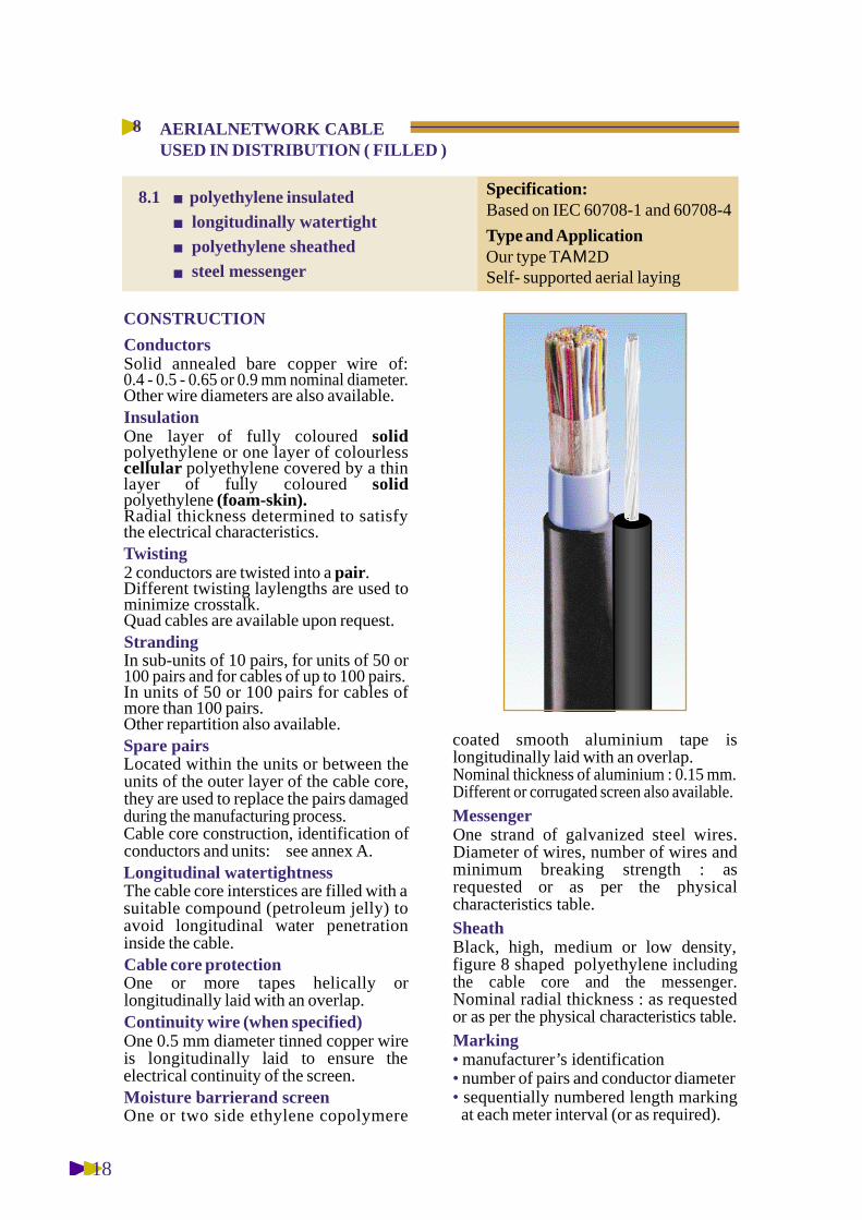
ConductorsSolid annealed bare copper wire of:0.4 - 0.5 - 0.65 or 0.9 mm nominal diameter.Other wire diameters are also available.InsulationOne layer of fully coloured s o l i dpolyethylene or one layer of colourlessc e l l u l a r polyethylene covered by a thinlayer of fully coloured s o l i dpolyethylene (foam-skin).Radial thickness determined to satisfythe electrical characteristics.Twisting2 conductors are twisted into a pair.D i fferent twisting laylengths are used tominimize crosstalk.Quad cables are available upon request.StrandingIn sub-units of 10 pairs, for units of 50 or100 pairs and for cables of up to 100 pairs.In units of 50 or 100 pairs for cables ofmore than 100 pairs.Other repartition also available.Spare pairsLocated within the units or between theunits of the outer layer of the cable core,they are used to replace the pairs damagedduring the manufacturing process.Cable core construction, identification ofconductors and units: see annex A.Longitudinal watertightnessThe cable core interstices are filled with asuitable compound (petroleum jelly) toavoid longitudinal water penetrationinside the cable.Cable core protectionOne or more tapes helically orlongitudinally laid with an overlap.Continuity wire (when specified)One 0.5 mm diameter tinned copper wireis longitudinally laid to ensure theelectrical continuity of the screen.Moisture barrierand screenOne or two side ethylene copolymere
CONSTRUCTION
coated smooth aluminium tape islongitudinally laid with an overlap.Nominal thickness of aluminium : 0.15 mm.Different or corrugated screen also available.MessengerOne strand of galvanized steel wires.Diameter of wires, number of wires andminimum breaking strength : asrequested or as per the physicalcharacteristics table.SheathBlack, high, medium or low density,figure 8 shaped polyethylene i n c l u d i n gthe cable core and the messenger.Nominal radial thickness : as requestedor as per the physical characteristics table.Marking• manufacturer’s identification• number of pairs and conductor diameter• sequentially numbered length markingat each meter interval (or as required).
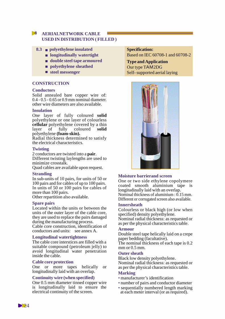
AERIALNETWORK CABLEUSED IN DISTRIBUTION ( FILLED )
8
Specification:Based on IEC 60708-1 and 60708-4
Type and ApplicationOur type TΑΜ2DSelf- supported aerial laying
8.1 polyethylene insulatedlongitudinally watertightpolyethylene sheathedsteel messenger

19
Loop resistance at 20ºC in direct current
Diametermm
NominalvalueΩ/km
Maximumindividual value
Ω/km0.40.50.60.650.80.91.2
288.0184.2127.8106.070.656.030.0
300.0191.8133.2114.073.660.032.0
Dielectric strength during 1 mn in direct current*Between conductors: 0.5 kvBetween conductors and screen : 1 kv* the test can be achieved under alternative currentwith half of above voltages.
Insulation resistance under 200 V minimum directcurrentLowest value after 2 mn minimum : 5000 MΩ.km.
Mutual capacitance at 800 HzMaximum individual: 64 nF/km.For cables of equal or more than 20 pairs:maximum average: 55 nF/km.cables of low level mutual capacitance (42 nF/km)are also available
Maximum capacitance unbalance at 800 Hz in pFper500 meters length of cable.
Maximum calculated attenuation at 800 Hz and 20ºC
ø 0.4 mm 1.79 dB/kmø 0.5 mm 1.43 dB/kmø 0.65 mm 1.11 dB/kmø 0.9 mm 0.81 dB/km
Usual electrical characteristics
Pair-to-pair
Side-to-side
Pair-to-earth
Side-to-earth
250
800
160
500
1700
1700
150
500
100
300
1000
1000
0.8 mm0.4, 0.5 & 0.6 mm0.8 mm0.4, 0.5 & 0.6 mm
Individual value (pF) 95% values (pF)
20
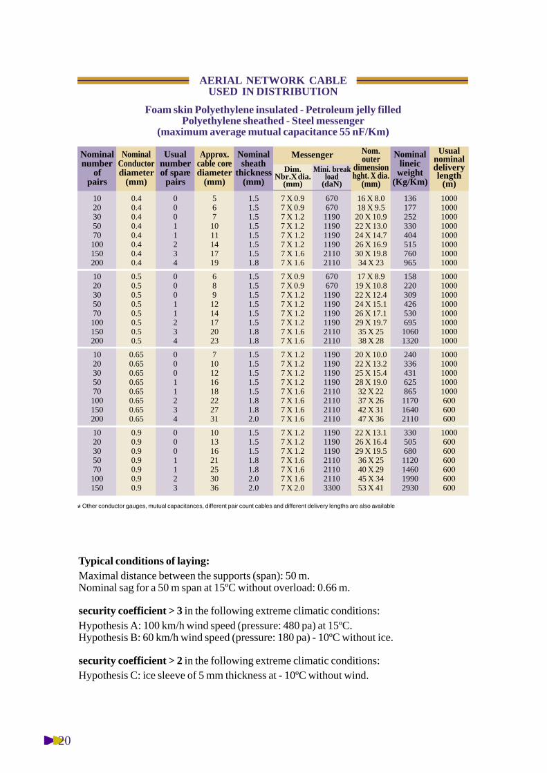
Foam skin Polyethylene insulated - Petroleum jelly filledPolyethylene sheathed - Steel messenger
(maximum average mutual capacitance 55 nF/Km)
1020305070100150200
1020305070100150200
1020305070100150200
1020305070100150
AERIAL NETWORK CABLEUSED IN DISTRIBUTION
Nominalnumber
ofpairs
0.40.40.40.40.40.40.40.4
0.50.50.50.50.50.50.50.5
0.650.650.650.650.650.650.650.65
0.90.90.90.90.90.90.9
00011234
00011234
00011234
0001123
5671011141719
6891214172023
710121618222731
10131621253036
1.51.51.51.51.51.51.51.8
1.51.51.51.51.51.51.81.8
1.51.51.51.51.51.81.82.0
1.51.51.51.81.82.02.0
7 X 0.97 X 0.97 X 1.27 X 1.27 X 1.27 X 1.27 X 1.67 X 1.6
7 X 0.97 X 0.97 X 1.27 X 1.27 X 1.27 X 1.27 X 1.67 X 1.6
7 X 1.27 X 1.27 X 1.27 X 1.27 X 1.67 X 1.67 X 1.67 X 1.6
7 X 1.27 X 1.27 X 1.27 X 1.67 X 1.67 X 1.67 X 2.0
670670119011901190119021102110
670670119011901190119021102110
11901190119011902110211021102110
1190119011902110211021103300
16 X 8.018 X 9.5
20 X 10.922 X 13.024 X 14.726 X 16.930 X 19.834 X 23
17 X 8.919 X 10.822 X 12.424 X 15.126 X 17.129 X 19.735 X 2538 X 28
20 X 10.022 X 13.225 X 15.428 X 19.032 X 2237 X 2642 X 3147 X 36
22 X 13.126 X 16.429 X 19.536 X 2540 X 2945 X 3453 X 41
136177252330404515760965
15822030942653069510601320
240336431625865117016402110
3305056801120146019902930
10001000100010001000100010001000
10001000100010001000100010001000
10001000100010001000600600600
1000600600600600600600
NominalConductordiameter
(mm)
Usualnumberof spare
pairs
Nominalsheath
thickness(mm)
Nom.outer
dimensionhght. X dia.
(mm)
Usualnominaldeliverylength
(m)
Nominallineic
weight(Kg/Km)
MessengerApprox.cable corediameter
(mm)Dim.
Nbr.X dia.(mm)
Mini. breakload
(daN)
Typical conditions of laying:Maximal distance between the supports (span): 50 m.Nominal sag for a 50 m span at 15ºC without overload: 0.66 m.
security coefficient > 3 in the following extreme climatic conditions:Hypothesis A: 100 km/h wind speed (pressure: 480 pa) at 15ºC.Hypothesis B: 60 km/h wind speed (pressure: 180 pa) - 10ºC without ice.
security coefficient > 2 in the following extreme climatic conditions:Hypothesis C: ice sleeve of 5 mm thickness at - 10ºC without wind.
* Other conductor gauges, mutual capacitances, different pair count cables and different delivery lengths are also available

21
ConductorsSolid annealed bare copper wire of:0.4 - 0.5 - 0.65 or 0.9 mm nominal diameter.Other wire diameters are also available.InsulationOne layer of fully coloured s o l i dpolyethylene or one layer of colourlessc e l l u l a r polyethylene covered by a thinlayer of fully coloured s o l i dpolyethylene (foam-skin).Radial thickness determined to satisfythe electrical characteristics.Twisting2 conductors are twisted into a pair.D i fferent twisting laylengths are used tominimize crosstalk.Quad cables are available upon request.StrandingIn sub-units of 10 pairs, for units of 50 or100 pairs and for cables of up to 100 pairs.In units of 50 or 100 pairs for cables ofmore than 100 pairs.Other repartition also available.Spare pairsLocated within the units or between theunits of the outer layer of the cable core,they are used to replace the pairs damagedduring the manufacturing process.Cable core construction, identification ofconductors and units: see annex A.Cable core protectionOne or more tapes helically orlongitudinally laid with an overlap.Continuity wire (when specified)One 0.5 mm diameter tinned copper wireis longitudinally laid to ensure theelectrical continuity of the screen.Moisture barrierand screenOne or two side ethylene copolymerecoated smooth aluminium tape islongitudinally laid with an overlap.Nominal thickness of aluminium : 0.15 mm.Different or corrugated screen also available.
CONSTRUCTION
MessengerOne strand of galvanized steel wires.Diameter of wires, number of wires andminimum breaking strength : asrequested or as per the physicalcharacteristics table.
SheathBlack, high, medium or low density,figure 8 shaped polyethylene includingthe cable core and the messenger.Nominal radial thickness : as requestedor as per the physical characteristicstable.
Marking• manufacturer’s identification• number of pairs and conductor diameter• sequentially numbered length markingat each meter interval (or as required).
AERIALNETWORK CABLEUSED IN DISTRIBUTION ( AIRCORE )
8
Specification:Based on IEC 60708-1 and 60708-4
Type and ApplicationOur type TΑ2ΜDSelf- supported aerial laying
8.2 polyethylene insulated
polyethylene sheathed
steel messenger
22
Loop resistance at 20ºC in direct current
Diametermm
NominalvalueΩ/km
Maximumindividual value
Ω/km0.40.50.60.650.80.91.2
288.0184.2127.8106.070.656.030.0
300.0191.8133.2114.073.660.032.0
Dielectric strength during 1 mn in direct current*Between conductors: 0.5 kvBetween conductors and screen : 1 kv* the test can be achieved under alternative currentwith half of above voltages.
Insulation resistance under 200 V minimum directcurrentLowest value after 2 mn minimum : 5000 MΩ.km.
Mutual capacitance at 800 HzMaximum individual: 64 nF/km.For cables of equal or more than 20 pairs:maximum average: 55 nF/km.cables of low level mutual capacitance (42 nF/km)are also available
Maximum capacitance unbalance at 800 Hz in pFper500 meters length of cable.
Maximum calculated attenuation at 800 Hz and 20ºC
ø 0.4 mm 1.79 dB/kmø 0.5 mm 1.43 dB/kmø 0.65 mm 1.11 dB/kmø 0.9 mm 0.81 dB/km
Usual electrical characteristics
Pair-to-pair
Side-to-side
Pair-to-earth
Side-to-earth
250
800
160
500
1700
1700
150
500
100
300
1000
1000
0.8 mm0.4, 0.5 & 0.6 mm0.8 mm0.4, 0.5 & 0.6 mm
Individual value (pF) 95% values (pF)

23
Foam skin Polyethylene insulated - Polyethylene sheathed - Steel messenger(maximum average mutual capacitance 55 nF/Km)
1020305070100150200
1020305070100150200
1020305070100150200
1020305070100150
AERIAL NETWORK CABLEUSED IN DISTRIBUTION
Nominalnumber
ofpairs
0.40.40.40.40.40.40.40.4
0.50.50.50.50.50.50.50.5
0.650.650.650.650.650.650.650.65
0.90.90.90.90.90.90.9
00011234
00011234
00011234
0001123
5671011131619
5781113151921
69101316192327
9121419222632
1.51.51.51.51.51.51.51.5
1.51.51.51.51.51.51.51.8
1.51.51.51.51.51.81.81.8
1.51.51.51.51.81.81.9
7 X 0.97 X 0.97 X 1.27 X 1.27 X 1.27 X 1.27 X 1.67 X 1.6
7 X 0.97 X 0.97 X 1.27 X 1.27 X 1.27 X 1.27 X 1.67 X 1.6
7 X 1.27 X 1.27 X 1.27 X 1.27 X 1.67 X 1.67 X 1.67 X 1.6
7 X 1.27 X 1.27 X 1.27 X 1.67 X 1.67 X 1.67 X 2.0
670670119011901190119021102110
670670119011901190119021102110
11901190119011902110211021102110
1190119011902110211021103300
16 X 8.018 X 9.420 X 10.722 X 12.924 X 14.626 X 16.730 X 19.633 X 23
17 X 8.619 X 10.321 X 11.723 X 14.125 X 16.128 X 18.532 X 2236 X 26
19 X 9.821 X 11.923 X 13.926 X 16.830 X 19.234 X 2338 X 2842 X 31
21 X 12.124 X 15
27 X 17.632 X 2237 X 2641 X 3148 X 37
129166234306370466680840
1481982803784726108951140
21629537353074099513701730
291440585940125016802470
10001000100010001000100010001000
10001000100010001000100010001000
10001000100010001000600600600
1000600600600600600600
NominalConductordiameter
(mm)
Usualnumberof spare
pairs
Nominalsheath
thickness(mm)
Nom.outer
dimensionhght. X dia.
(mm)
Usualnominaldeliverylength
(m)
Nominallineic
weight(Kg/Km)
MessengerApprox.cable corediameter
(mm)Dim.
Nbr.X dia.(mm)
Mini. breakload
(daN)
Typical conditions of laying:Maximal distance between the supports (span): 50 m.Nominal sag for a 50 m span at 15ºC without overload: 0.66 m.
security coefficient > 3 in the following extreme climatic conditions:Hypothesis A : 100 km/h wind speed (pressure: 480 pa) at 15ºC.Hypothesis B : 60 km/h wind speed (pressure: 180 pa) - 10ºC without ice.
security coefficient > 2 in the following extreme climatic conditions:Hypothesis C : ice sleeve of 5 mm thickness at - 10ºC without wind.
* Other conductor gauges, mutual capacitances, different pair count cables and different delivery lengths are also available
24
ConductorsSolid annealed bare copper wire of:0.4 - 0.5 - 0.65 or 0.9 mm nominal diameter.other wire diameters are also available.InsulationOne layer of fully coloured s o l i dpolyethylene or one layer of colourlessc e l l u l a r polyethylene covered by a thinlayer of fully coloured s o l i dpolyethylene (foam-skin).Radial thickness determined to satisfythe electrical characteristics.Twisting2 conductors are twisted into a pair.D i fferent twisting laylengths are used tominimize crosstalk.Quad cables are available upon request.StrandingIn sub-units of 10 pairs, for units of 50 or100 pairs and for cables of up to 100 pairs.In units of 50 or 100 pairs for cables ofmore than 100 pairs.Other repartition also available.Spare pairsLocated within the units or between theunits of the outer layer of the cable core,they are used to replace the pairs damagedduring the manufacturing process.Cable core construction, identification ofconductors and units: see annex A.Longitudinal watertightnessThe cable core interstices are filled with asuitable compound (petroleum jelly) toavoid longitudinal water penetrationinside the cable.Cable core protectionOne or more tapes helically orlongitudinally laid with an overlap.Continuity wire (when specified)One 0.5 mm diameter tinned copper wireis longitudinally laid to ensure theelectrical continuity of the screen.
CONSTRUCTION
Moisture barrierand screenOne or two side ethylene copolymerecoated smooth aluminium tape islongitudinally laid with an overlap.Nominal thickness of aluminium : 0.15 mm.Different or corrugated screen also available.InnersheathColourless or black high (or low whenspecified) density polyethylene.Nominal radial thickness: as requested oras per the physical characteristics table.ArmourDouble steel tape helically laid on a crepepaper bedding (facultative).The nominal thickness of each tape is 0.2mm or 0.5 mm.Outer sheathBlack low density polyethylene.Nominal radial thickness: as requested oras per the physical characteristics table.Marking• manufacturer’s identification• number of pairs and conductor diameter• sequentially numbered length markingat each meter interval (or as required).
AERIALNETWORK CABLEUSED IN DISTRIBUTION ( FILLED )
8
Specification:Based on IEC 60708-1 and 60708-2
Type and ApplicationOur type TΑΜ2DGSelf- supported aerial laying
8.3 polyethylene insulatedlongitudinally watertightdouble steel tape armouredpolyethylene sheathedsteel messenger
25
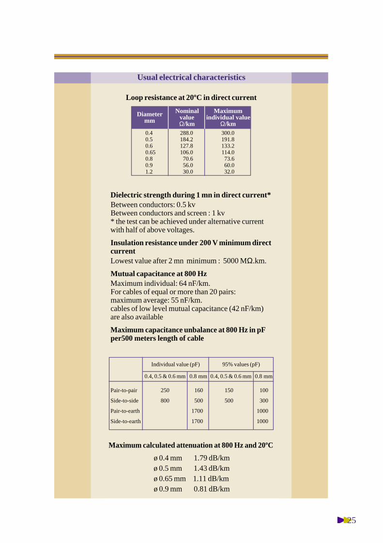
Loop resistance at 20ºC in direct current
Diametermm
NominalvalueΩ/km
Maximumindividual value
Ω/km0.40.50.60.650.80.91.2
288.0184.2127.8106.070.656.030.0
300.0191.8133.2114.073.660.032.0
Dielectric strength during 1 mn in direct current*Between conductors: 0.5 kvBetween conductors and screen : 1 kv* the test can be achieved under alternative currentwith half of above voltages.
Insulation resistance under 200 V minimum directcurrentLowest value after 2 mn minimum : 5000 MΩ.km.
Mutual capacitance at 800 HzMaximum individual: 64 nF/km.For cables of equal or more than 20 pairs:maximum average: 55 nF/km.cables of low level mutual capacitance (42 nF/km)are also available
Maximum capacitance unbalance at 800 Hz in pFper500 meters length of cable
Maximum calculated attenuation at 800 Hz and 20ºC
ø 0.4 mm 1.79 dB/kmø 0.5 mm 1.43 dB/kmø 0.65 mm 1.11 dB/kmø 0.9 mm 0.81 dB/km
Usual electrical characteristics
Pair-to-pair
Side-to-side
Pair-to-earth
Side-to-earth
250
800
160
500
1700
1700
150
500
100
300
1000
1000
0.8 mm0.4, 0.5 & 0.6 mm0.8 mm0.4, 0.5 & 0.6 mm
Individual value (pF) 95% values (pF)

26
Foam skin Polyethylene insulated - Petroleum jelly filled - Double steel tape armouredPolyethylene sheathed - Steel messenger
(maximum average mutual capacitance 55 nF/Km)
1020305070100150200
1020305070100150200
1020305070100150200
1020305070100150
AERIAL NETWORK CABLEUSED IN DISTRIBUTION
Nominalnumber
ofpairs
0.40.40.40.40.40.40.40.4
0.50.50.50.50.50.50.50.5
0.650.650.650.650.650.650.650.65
0.90.90.90.90.90.90.9
00011234
00011234
00011234
0001123
5681011141719
6891214172023
710121619222731
10131621253036
7 X 1.27 X 1.27 X 1.27 X 1.27 X 1.27 X 1.27 X 1.67 X 1.6
7 X 1.27 X 1.27 X 1.27 X 1.27 X 1.67 X 1.67 X 1.67 X 1.6
7 X 1.27 X 1.27 X 1.27 X 1.27 X 1.67 X 1.67 X 1.67 X 1.6
7 X 1.27 X 1.27 X 1.27 X 1.67 X 1.67 X 1.67 X 2.0
11901190119011901190119021102110
11901190119011902110211021102110
11901190119011902110211021102110
1190119011902110211021103300
21 X 12.223 X 13.724 X 14.926 X 17.128 X 18.730 X 2135 X 2539 X 28
22 X 13.021 X 14.926 X 16.528 X 19.132 X 2235 X 2540 X 2943 X 33
24 X 14.727 X 17.329 X 19.433 X 2437 X 2742 X 3147 X 3652 X 41
26 X 17.130 X 2134 X 2540 X 3045 X 3450 X 3960 X 47
29535440751561074510601300
325408485635830105014101740
3935256459151190155021002630
5157359701480190025003610
10001000100010001000100010001000
10001000100010001000100010001000
10001000100010001000600600600
1000600600600600600600
NominalConductordiameter
(mm)
Usualnumberof spare
pairs
Nom.outer
dimensionhght. X dia.
(mm)
Usualnominaldeliverylength
(m)
Nominallineic
weight(Kg/Km)
MessengerApprox.cable corediameter
(mm)Dim.
Nbr.X dia.(mm)
Mini. breakload
(daN)
Typical conditions of laying:Maximal distance between the supports (span): 50 m.Nominal sag for a 50 m span at 15ºC without overload: 0.66 m.
security coefficient > 3 in the following extreme climatic conditions:Hypothesis A : 100 km/h wind speed (pressure: 480 pa) at 15ºC.Hypothesis B : 60 km/h wind speed (pressure: 180 pa) - 10ºC without ice.
security coefficient > 2 in the following extreme climatic conditions:Hypothesis C : ice sleeve of 5 mm thickness at - 10ºC without wind.
1.51.51.51.51.51.51.51.8
1.51.51.51.51.51.51.81.8
1.51.51.51.51.51.81.82.0
1.51.51.51.81.82.02.0
1.51.51.51.51.51.51.81.8
1.51.51.51.51.51.81.82.0
1.51.51.51.81.81.82.02.0
1.51.51.81.82.02.02.5
Nominalsheath
thickness(mm)
Inner Outer
* Other conductor gauges, mutual capacitances, different pair count cables and different delivery lengths are also available

27
ConductorsSolid annealed bare copper wire of:0.4 - 0.5 - 0.65 or 0.9 mm nominal diameter.InsulationOne layer of fully coloured s o l i dpolyethylene or one layer of colourlessc e l l u l a r polyethylene covered by a thinlayer of fully coloured s o l i dpolyethylene (foam-skin).Radial thickness determined to satisfythe electrical characteristics.Twisting2 conductors are twisted into a pair.D i fferent twisting laylengths are used tominimize crosstalk.Quad cables are available upon request.StrandingIn sub-units of 10 pairs, for units of 50 or100 pairs and for cables of up to 100 pairs.In units of 50 or 100 pairs for cables ofmore than 100 pairs.Other repartition also available.Spare pairsLocated within the units or between theunits of the outer layer of the cable core,they are used to replace the pairs damagedduring the manufacturing process.Cable core construction, identification ofconductors and units: see annex A.Cable core protectionOne or more tapes helically orlongitudinally laid with an overlap.Continuity wire (when specified)One 0.5 mm diameter tinned copper wireis longitudinally laid to ensure theelectrical continuity of the screen.Moisture barrierand screenOne or two side ethylene copolymerecoated smooth aluminium tape islongitudinally laid with an overlap.Nominal thickness of aluminium : 0.15 mm.Different or corrugated screen also available.
CONSTRUCTION
Inner sheathColourless or black high (or low whenspecified) density polyethylene.Nominal radial thickness: as requested oras per the physical characteristics table.
ArmourDouble steel tape helically laid on a crepepaper bedding (facultative).The nominal thickness of each tape is 0.2mm or 0.5 mm
OutersheathBlack low density polyethylene.Nominal radial thickness: as requested oras per the physical characteristics table.
Marking• manufacturer’s identification• number of pairs and conductor diameter• sequentially numbered length markingat each meter interval (or as required).
AERIALNETWORK CABLEUSED IN DISTRIBUTION ( AIRCORE )
8
Specification:Based on IEC 60708-1 and 60708-3
Type and ApplicationOur type TΑ2ΜDGSelf- supported aerial laying
8.3 polyethylene insulateddouble steel tape armouredpolyethylene sheathedsteel messenger
28
Loop resistance at 20ºC in direct current
Diametermm
NominalvalueΩ/km
Maximumindividual value
Ω/km0.40.50.60.650.80.91.2
288.0184.2127.8106.070.656.030.0
300.0191.8133.2114.073.660.032.0
Dielectric strength during 1 mn in direct current*Between conductors: 0.5 kvBetween conductors and screen : 1 kv* the test can be achieved under alternative currentwith half of above voltages.
Insulation resistance under 200 V minimum directcurrentLowest value after 2 mn minimum : 5000 MΩ.km.
Mutual capacitance at 800 HzMaximum individual: 64 nF/km.For cables of equal or more than 20 pairs:maximum average: 55 nF/km.cables of low level mutual capacitance (42 nF/km)are also available
Maximum capacitance unbalance at 800 Hz in pFper 500 meters length of cable
Maximum calculated attenuation at 800 Hz and 20ºC
ø 0.4 mm 1.79 dB/kmø 0.5 mm 1.43 dB/kmø 0.65 mm 1.11 dB/kmø 0.9 mm 0.81 dB/km
Usual electrical characteristics
Pair-to-pair
Side-to-side
Pair-to-earth
Side-to-earth
250
800
160
500
1700
1700
150
500
100
300
1000
1000
0.8 mm0.4, 0.5 & 0.6 mm0.8 mm0.4, 0.5 & 0.6 mm
Individual value (pF) 95% values (pF)
29
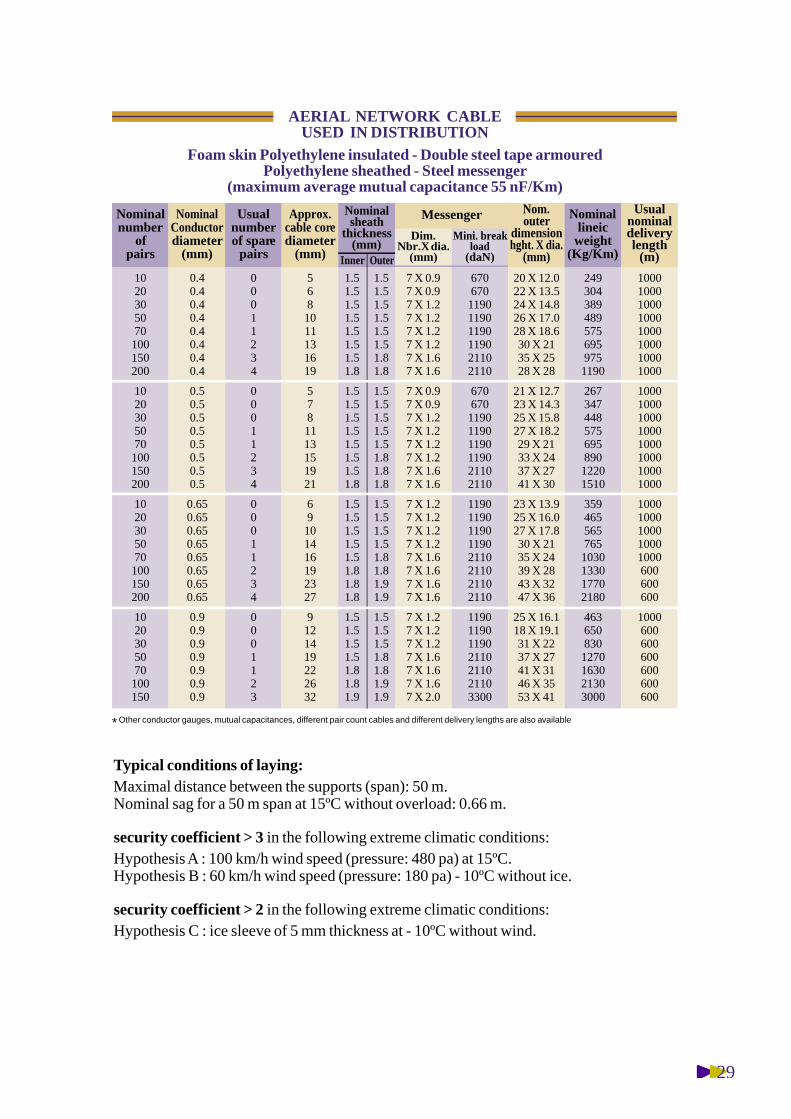
Foam skin Polyethylene insulated - Double steel tape armouredPolyethylene sheathed - Steel messenger
(maximum average mutual capacitance 55 nF/Km)
1020305070100150200
1020305070100150200
1020305070100150200
1020305070100150
AERIAL NETWORK CABLEUSED IN DISTRIBUTION
Nominalnumber
ofpairs
0.40.40.40.40.40.40.40.4
0.50.50.50.50.50.50.50.5
0.650.650.650.650.650.650.650.65
0.90.90.90.90.90.90.9
00011234
00011234
00011234
0001123
5681011131619
5781113151921
69101416192327
9121419222632
7 X 0.97 X 0.97 X 1.27 X 1.27 X 1.27 X 1.27 X 1.67 X 1.6
7 X 0.97 X 0.97 X 1.27 X 1.27 X 1.27 X 1.27 X 1.67 X 1.6
7 X 1.27 X 1.27 X 1.27 X 1.27 X 1.67 X 1.67 X 1.67 X 1.6
7 X 1.27 X 1.27 X 1.27 X 1.67 X 1.67 X 1.67 X 2.0
670670119011901190119021102110
670670119011901190119021102110
11901190119011902110211021102110
1190119011902110211021103300
20 X 12.022 X 13.524 X 14.826 X 17.028 X 18.630 X 2135 X 2528 X 28
21 X 12.723 X 14.325 X 15.827 X 18.229 X 2133 X 2437 X 2741 X 30
23 X 13.925 X 16.027 X 17.830 X 2135 X 2439 X 2843 X 3247 X 36
25 X 16.118 X 19.131 X 2237 X 2741 X 3146 X 3553 X 41
2493043894895756959751190
26734744857569589012201510
3594655657651030133017702180
4636508301270163021303000
10001000100010001000100010001000
10001000100010001000100010001000
10001000100010001000600600600
1000600600600600600600
NominalConductordiameter
(mm)
Usualnumberof spare
pairs
Nom.outer
dimensionhght. X dia.
(mm)
Usualnominaldeliverylength
(m)
Nominallineic
weight(Kg/Km)
MessengerApprox.cable corediameter
(mm)Dim.
Nbr.X dia.(mm)
Mini. breakload
(daN)
Typical conditions of laying:Maximal distance between the supports (span): 50 m.Nominal sag for a 50 m span at 15ºC without overload: 0.66 m.
security coefficient > 3 in the following extreme climatic conditions:Hypothesis A : 100 km/h wind speed (pressure: 480 pa) at 15ºC.Hypothesis B : 60 km/h wind speed (pressure: 180 pa) - 10ºC without ice.
security coefficient > 2 in the following extreme climatic conditions:Hypothesis C : ice sleeve of 5 mm thickness at - 10ºC without wind.
1.51.51.51.51.51.51.51.8
1.51.51.51.51.51.51.51.8
1.51.51.51.51.51.81.81.8
1.51.51.51.51.81.81.9
1.51.51.51.51.51.51.81.8
1.51.51.51.51.51.81.81.8
1.51.51.51.51.81.81.91.9
1.51.51.51.81.81.91.9
Nominalsheath
thickness(mm)
Inner Outer
* Other conductor gauges, mutual capacitances, different pair count cables and different delivery lengths are also available
30
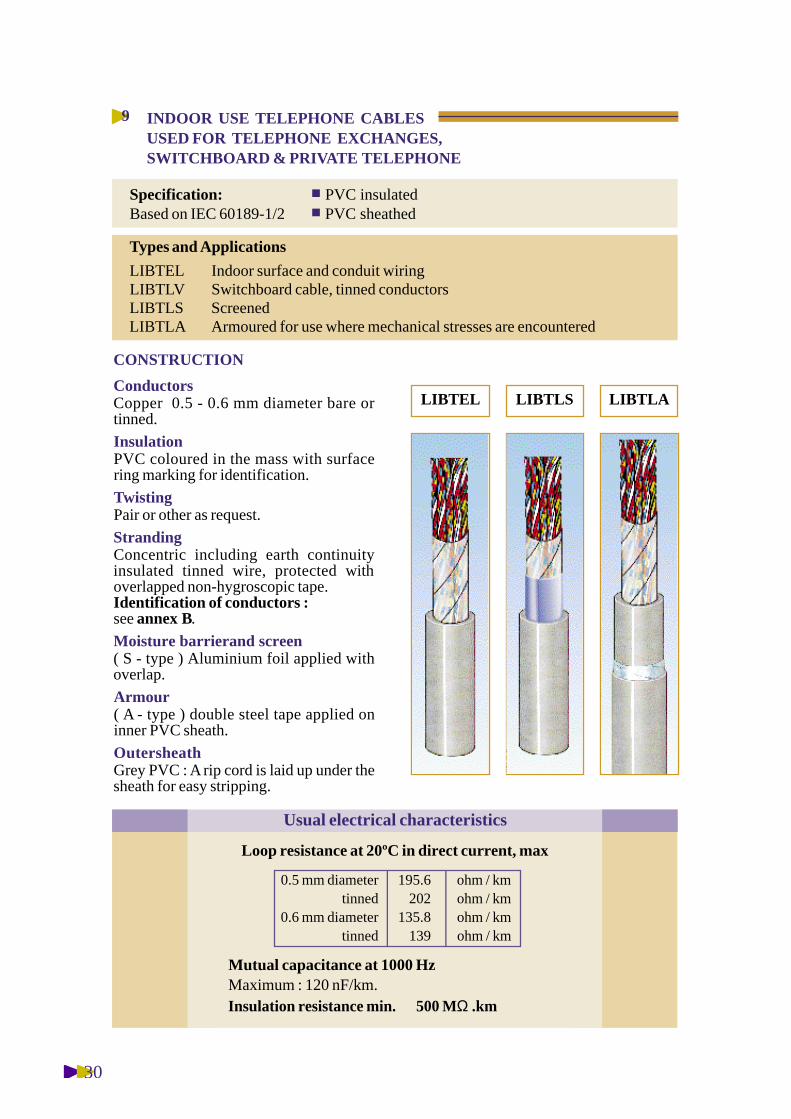
ConductorsCopper 0.5 - 0.6 mm diameter bare ortinned.
InsulationPVC coloured in the mass with surfacering marking for identification.
TwistingPair or other as request.
StrandingConcentric including earth continuityinsulated tinned wire, protected withoverlapped non-hygroscopic tape.Identification of conductors : see annex B.
Moisture barrierand screen( S - type ) Aluminium foil applied withoverlap.
Armour( A - type ) double steel tape applied oninner PVC sheath.
OutersheathGrey PVC : A rip cord is laid up under thesheath for easy stripping.
INDOOR USE TELEPHONE CABLESUSED FOR TELEPHONE EXCHANGES,SWITCHBOARD & PRIVATE TELEPHONE
9
Specification:Based on IEC 60189-1/2
PVC insulatedPVC sheathed
Types and Applications
LIBTELLIBTLVLIBTLSLIBTLA
Indoor surface and conduit wiringSwitchboard cable, tinned conductorsScreenedArmoured for use where mechanical stresses are encountered
CONSTRUCTION
Loop resistance at 20ºC in direct current, max
0.5 mm diametertinned
0.6 mm diametertinned
195.6202
135.8139
ohm / kmohm / kmohm / kmohm / km
Mutual capacitance at 1000 HzMaximum : 120 nF/km.Insulation resistance min. 500 MΩ .km
Usual electrical characteristics
LIBTEL LIBTLS LIBTLA

31
PVC insulated and PVC sheathed
123
456
789
101520
253040
5070100
112227
323741
465155
67100118
151176236
273387510
3.84.85.1
5.45.85.9
6.16.66.7
6.88
8.8
9.610.512.5
13.515
17.5
202834
404650
566770
72105131
157182243
299397555
Type LIBTELS Type LIBTELA
---------
---------
---------
172208245
280314394
463585770
100100100
100100100
100100100
500 / 1000500 / 1000500 / 1000
500 / 1000500 / 1000500 / 1000
500 / 1000500 / 1000500 / 1000
---------
---------
---------
1010.511.5
12.513
14.5
1617.521
CCC
CCC
CCC
DDD
DDD
DDD
34.24.5
4.95.25.3
5.55.75.9
6.47.78.6
9.51012
1315
17.5
Type LIBTELLIBTLV
INDOOR USETELEPHONE CABLES
Nominalnumber
ofpairs
Netweightkg / km
NominalOverall
diameter(mm)
NominalOverall
diameter(mm)
StandardPacking
Standard Packing : C : CoilsD : Drums
Other Sizes are also available
Netweightkg / km
Netweightkg / km
Deliverylength
m
NominalOverall
diameter(mm)
CONDUCTOR DIAMETER 0.5 mm

32
ConductorSolid, annealed, bare or tinned copperwire, diameter 0.5 mm.
InsulationPVC coloured for identification.
Jacket(type JWN and JWVN) abrasion resistantnylon.
StrandingTwo to five conductors twisted together.
JUMPER WIRE10
ApplicationThese cables are intended for inside distributing frame jumper wiring
Types
JWJWVJWNJWVN
PVC insulatedtinned copper wire, PVC insulatedPVC insulated, nylon jacketedsame as JWN but with tinned conductor
CONSTRUCTION
DIMENSIONAL CHARACTERISTICS
Conductor resistance : max 92 Ω / kmInsulation resistance : min 1000 MΩ / km
Electrical characteristics at 20ºC
123
45
3.06.09.0
1215
1.12.22.4
2.73.0
2.85.78.5
11.514.0
Type JWN
500500500
250250
1.12.22.4
2.73.0
Type JW/V
Numberof
conductors
Netweightkg / km
Overalldiameter
(mm)
Deliverylength( coils )
m
Netweightkg / km
Overalldiameter
(mm)
CONDUCTOR DIAMETER 0.5 mm

33
ConductorHard copper wire
Laid-UpThe two conductors are laid-up paralleland jacketed. A ridge is longitudinallyextruded along one edge for conductoridentification
JacketDWIRE type : Black polyethylene type2 C to BS 6234
DWIREY type: Hard PVC tightly adheredto the conductor type 2 to BS 6746
DROP WIRE11
Application
These cables are intended for connecting telephone aerial cable to thesubscriber’s premises
Types
DWIRE
DWIREY
Hard copper conductor, PE jacketed
Hard copper conductor, PVC jacketed
CONSTRUCTION
Conductor resistance, max.- Hard drawn copper
Insulation resistance, min.- PE jacketed- PVC jacketed
0.8 mm diameter0.9 mm diameter1.0 mm diameter
35.028.024.0
Ω / kmΩ / kmΩ / km
Electrical characteristics at 20ºC
5000100
MΩ . kmMΩ . km
DIMENSIONAL CHARACTERISTICS
DWIRE
DWIREY
PEPEPE
PVCPVCPVC
2.6 X 5.72.7 X 5.93.0 X 6.5
2.6 X 5.72.7 X 5.93.0 X 6.5
202328
242733
500500500
500500500
0.80.91.0
0.80.91.0
Type Jacketnature
Overalldimensions
width x heightmm
Netweightkg / km
CopperConductordiameter
mm
Deliverylength(coils)
m
34
ANNEX A
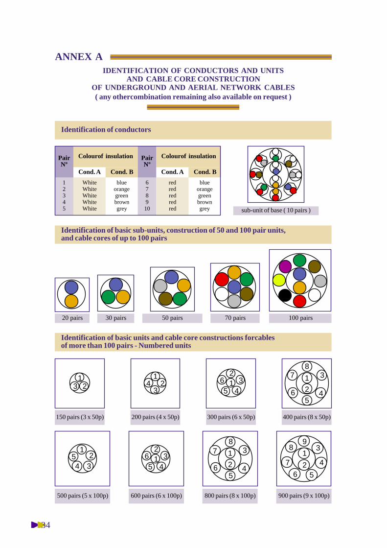
( any othercombination remaining also available on request )
IDENTIFICATION OF CONDUCTORS AND UNITSAND CABLE CORE CONSTRUCTION
OF UNDERGROUND AND AERIAL NETWORK CABLES
Identification of basic sub-units, construction of 50 and 100 pair units,and cable cores of up to 100 pairs
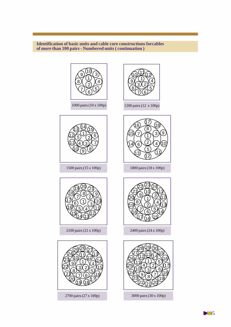
Identification of basic units and cable core constructions forcablesof more than 100 pairs - Numbered units
12345
blueorangegreenbrowngrey
WhiteWhiteWhiteWhiteWhite
PairNº
Colourof insulation
Cond. A Cond. B
678910
blueorangegreenbrowngrey
redredredredred
PairNº
Colourof insulation
Cond. A Cond. B
sub-unit of base ( 10 pairs )
50 pairs 70 pairs 100 pairs30 pairs20 pairs
800 pairs (8 x 100p)
150 pairs (3 x 50p) 300 pairs (6 x 50p) 400 pairs (8 x 50p)
600 pairs (6 x 100p)
1 3
2 45
6
78
900 pairs (9 x 100p)
1 32
456
1
32
45
500 pairs (5 x 100p)
1 3
2 45
6
78
1 32
4561
324
200 pairs (4 x 50p)
123
13
2 4
56
7
89
Identification of conductors
35
1000 pairs (10 x 100p)
13 2
4
567
8
910 1211
1200 pairs (12 x 100p)
13
24
56
7
8
910
1 3
2 45
6
78
9
10
1112
13
14
15
1617
18
1
32
45 6
78910
11
121513 14
13
24
567
8
910 11
12
13
14151617
18
19
2021
22 23 24
2400 pairs (24 x 100p)
1 3
2
4567
8 9
10
1112
131415
16
17
1819 20 21
2100 pairs (21 x 100p)
1800 pairs (18 x 100p)1500 pairs (15 x 100p)
1
324
5
6789
10
1112 13 14
1516
17
1819
20212223
24
25
2627
28 29 30
3000 pairs (30 x 100p)
13 2
4
567
8
910 11 12
1314
15
1617
181920
21
22
2324
25 26 27
2700 pairs (27 x 100p)
Identification of basic units and cable core constructions forcablesof more than 100 pairs - Numbered units ( continuation )

36
1234567891011121314151617181920212223242526272829303132
etc...
WhiteWhiteWhiteWhiteWhiteWhiteWhiteWhiteWhiteWhiteWhiteWhiteWhiteWhiteWhiteWhiteWhiteWhiteWhiteWhiteWhiteWhiteWhiteWhiteWhiteWhiteWhiteWhiteWhiteWhiteWhiteWhite
__________
RedRedRedRedRedBlueBlueBlueBlueBlue
YellowYellowYellowYellowYellowGreenGreenGreenGreenGreenBlackBlackBlackBlackBlack
____
PairNº
Basic
Wire B
Ring
ANNEX B
Identification of conductors in Indooruse telephone cables - LIBTEL
RedBlue
YellowGreenBlackRedBlue
YellowGreenBlackRedBlue
YellowGreenBlackRedBlue
YellowGreenBlackRedBlue
YellowGreenBlackRedBlue
YellowGreenBlackRedBlue
WireA
Colorcode
- Color of insulation of 1 triadWire A : Blue Wire B : White Wire C : Red


![Afnor certification-afaq-26000-guide[1]](https://img.dokumen.tips/doc/110x75/5571bfacd8b42ac0228b4f8e/afnor-certification-afaq-26000-guide1.jpg)


