Embed Size (px)
Citation preview

SPECIFIC'ATION FOR CENTRIFUGAL FANS
( First Revision 1 -- - --
?'L:rd Repnnt JmZOOC)

SPECIFICATION FOR CENTRIFklGAL, FANS
( First Revision )
0.1 This Indian Standard ( First Revision ) was adopted by the Bureau of Indian Standards on 27 August 1987, after the +aft finalized by the Electric FansTS6ciional Committee h a d ' becn approved by the Electrotichnical Division ek-unci1. ' 0.2 This standard was originally published in 1968. This revision hm bee; undertaken to take into acmunr the experience gained since then and to align some of the safety reqairements with the provisions of IS : 302-1979f. T h e amendments issued to the prtvious edition of the standard have also been incarporated in this revision.
i 0.3 The centrifugal fans covered by this standard 1 +General and safety rwuirsments for household and
-3 similar ~ l e c t r i w ! app!ianrer (j5,Qh rrgs?'on ).
are capable of' working against p m u r ~ s .
0.4 In preparing this standard, some assistance has becn drawn from BS 848 : Part 1 : 1980 [Fans for general purposes : Part 1 Methods of . testing performance', issued by the British Stand- ards Institution.
0.5 For the purpose of deciding whether a parti- cular requirement of this standard Ls complied with, the final valuc, observed or calculated, expressing the result of atest, shall be rounded off in accordance with I S : 2-1960*. T h e number of significant places retained in + rounded off valuc should be the same as, that of the specified value in this standard.
.r...,.- .- ~ u i c 3 rot ruunding on" numeriCai vaiue, ( r m d ).
1 4 SCOPE :b -.
1.2 T h e fans for'@&"und& £ie?flow conditions are excludexj fro'dl;the scope of this standard.
1.3 Centrifugal fans for use in mines and hazar- dous atmospheres may requirt: additional requi- rements to be met, not covered by this standard.
2. TERMINOLOGY,
2.0 For the purpose of t h i s standard, the follow- ing definitions, in addifion to those given in IS . 1885 TFart 55 )-1981*, shall apply.
2,% Ceqtrifngal Fan - A fan in which ..the air leaves the impeller in a direction substantially at right angles,tori.F;axis. .( ; ., , , - - . ' . . . ! ? > .. , . i,' .
2.2 ]Fan"-- ~ . , r o & r ~ machine which maintains a continuous flbw -iif. air - a t a :press&e ratio not normally exceeding 1.3.
~ ~ ~ . -- ~E!er t ro techn ica l vocabuiar-jr Part 55 E1e:tiic f a n s .
NOTE - I n thi , specification, t h e term ' f a n ' shall be used to mean centrifugal fan = supplied, without any addition to t h e iolet or oiitlet, except where nlrh addition is specified.
2.3 Air - T h e term air has becn used as an abbreviation for (air or any other gas' except where referred to 2 s 'atmcspheAc air'.
2.4 Standard Air - Atmospheric air having a specified weight of 1.2 kg/rnn which is dry air at 20°C with a barornettic prcssure of 760 mrn Hg (W). 2.5 Absolute Pressure - T h a t pressure which is exerted equally in all direction5 at a point. The absolute pressure of the ambient atmosphere is the barometric prcssure.
2.6 Static Pressure - T h e difference between the absolute pressure at a point and absalatc pressure or the ambient atmosphere, It i s positive when above and negative when below the ambi- ent pressure.
2.7 Velocity Pressure - T h e p r k u r t equival- ent of the air velocity a t any particular point. It is always positive.
2.8 Total Pressure - T h e algebraic sum of the n r ~ ~ c i i r e grid rrC!2r,itv p ~ ~ ~ ~ ~ : ~ 2 : 2z.i p2r$i.- r. . .
cular point.
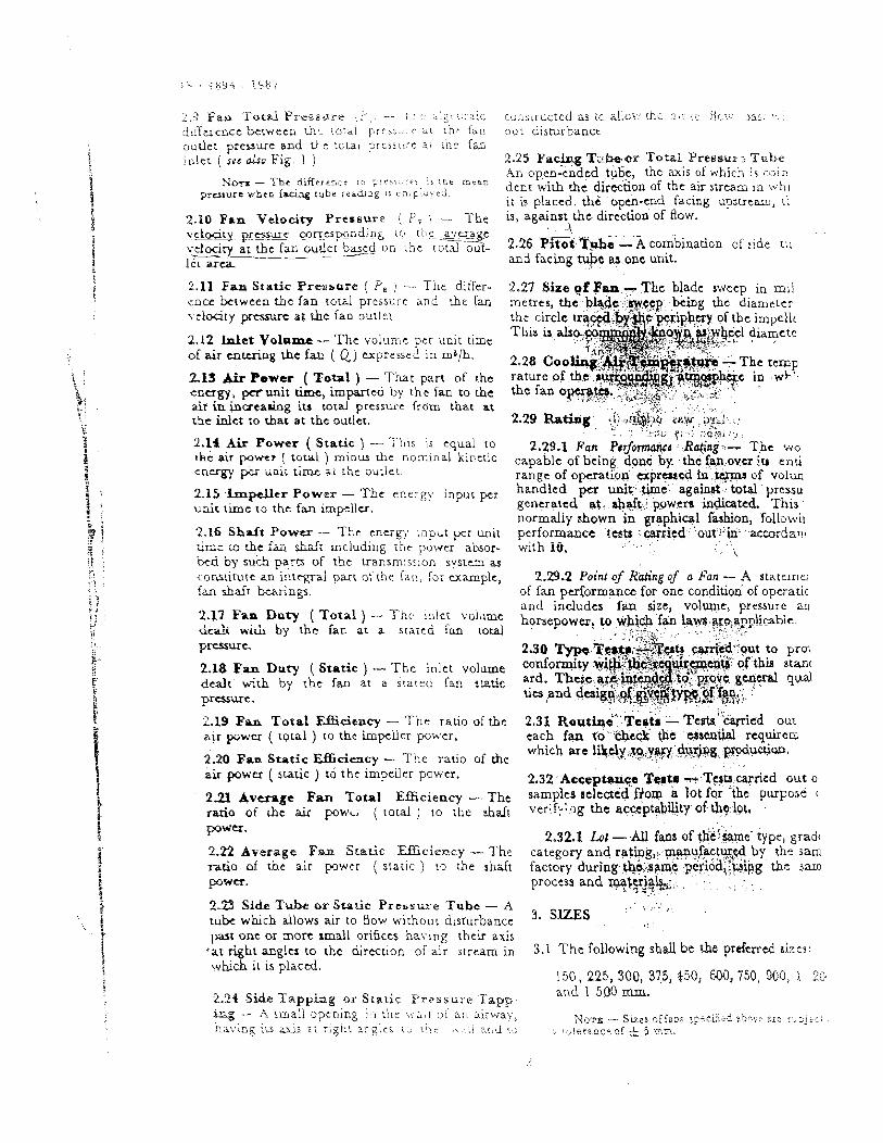
d:iference bcrweeo d ~ , to:ni p r c s ~ . , : ~ A: :!it ian ou i djsm-bancc ourlet pressure a d tk e t ~ t a i p r t s r t i r e ar ~ t 7 i far, inlet ( see a h Fig. i 2-25 Fac* T : i b ~ r 'Total Preseur 5 T c k
An open-ended tuce, the axis of which is coin N o r a - The d i f l r r r ~ c e i n Frt . i r , . . rc . - 1 s !tie rr.trs,
prusure when facing t u b e r e i r d i n g r r c n j plirkcd. dent w i h the direction of thc air stream in \..hi i.t is placed. the -open-end facing upsuearc, tk
2.10 Pan $'dodw Pressure ( P , 1 -- T h e bs, against.the direction of fbw. v c l w i p r s Q ca_r r_c~end .ng ~o t t ~ c - a_verirge f
vdocjry ~ a r , outlet hued o n \ h e rotd o ~ - 2.26 m T & e - A combination of side ru -- --a
12r arca a n d facisg *c as one unit,
2.11 F a n Static Pressere ( PP, i - The differ- encc berwcen the f an c o d pressure and b e fan
c l o d t y pt.gsurc at &e fan o u r l e ~
2.12 Inlet Volomc - T h e volurr~e per unit time of air cnrcriog the fa ( Q) expressed in mB/h. 2,28 2.13 f i P o w a ( Total ) - T h a t part of h e rature of energy, perunit time, imparted by the fan tothe the fano air inbcreadog ita total pressure from tba.t at rhc inlet to that at the outlet.
2.14 Air Power ( Static ) - This is equal to LBc air power ( t o t a l ) minus rhe nominal k i ~ e t i c c n w per i i a i r time sr thc ourlei.
2 1 5 lxnpeller Power - Thc energy input per unit t i m e 10 the fan impcllcr.
2.16 Shnit Power - T h e c n c r o input per wit GEt .e hc fa Nc k,c;iiding power absor- bed by such- E r n of the transm~ssion sysrcm a conslirurc an inrcgral part of the [an, Tor otamplc, fan shaft b r i n g s .
I I I C ' Z I , 2.29.1 Fan P s r f h a n a Ro(ing-- The wo
capable of being done by the faa over iu eari range of operation expressed in t cpu of volun handled unit time against , total pressu generated at. abaft powera indicated. This normally shown in graphical fashion, f01lo~n.u performmce testa cenicd out: in azmrdanl with iu.
\
2.29.2 Point of R&'ng of a Fan - A statcme. of fan puformance for one condition of operatic and includes fah size, volume, pressure an
2.17 Fan DntY ( ) - l'hc ln''' hpncpower, to ?hi,+ fp hw:ytiyplicabie. d d i w i d by i L c fan at a stared fan totai . , .,:<.P .... % , . -. : ....%!*,..>< ' . ' - - - -. ,-".-' . presurc 2.30 Typo.T~t~:-#iTtlf! ca&#!:;ut to pro1 . ;*,. ->: '--:
2-18 F a ISpty ( Static ) - The in le t volume ~0nf9mdty -Zi(i&:i%~$.i of-tbb stan( d d t w& by the fan at 3 r!aLcd fal r ~ c c md. tics and T h ~ c . a r @ h f ~ ~ ~ ~ F - ~ ~ . P ~ $ . d ~ g g ~ ; , o f o f ~ ~ ~ ~ ~ m . ~ a c ~ f H-,.; . 8 . ~ & : qd prenwc. , . 7 q . : . ~ , .., :Lysc~. .=:S* ; ..,':.
. . .. .. , . . , .
2.19 Pan Total Elfficimcy - The ratio of b e 2.31 Roatind."$estr - ~ e s t s " ~ k n i z d OU:
z.u power ( r o d ) ro thc impcller power. each fan fo'.che& the ebstntial r e q u i r c ~
2-20 Pan Static Efficiacy - The ratio of t h e which arc l i l r , . J y . ; ~ ~ ~ . ' . d ~ g . 8 8 ~ . ~ c ~ ~ . . . . .
air power ( static ) to t h c impeller power, 2.32 .Accep%?. Teat:# - Tqtscarricd out o 2 3 ~ bverPgc F- ~,,d Efficiency - The ~amplcs aclected f?om a lot for -the purpose (
of be ( j the shds ver;f::!lg the acceptability of&~lot , pawar.
2.32.1 Lot -All fans of th&rne' +pe, grad, 2.22 A v e r q e F m StgGr B c i e ~ l c y --. Ths category and rat ipg , , .wvfaCt~$by the j a m ratio, of h e air ( srauc ) to the shd t factory during .&&:am:$ .pe~j-idd,~p!pg the sm p w u . process and qalyj&,-.. .. 1 : , .,, :.
n . .
223 Side Tube or S t a t i c Press-L-e Tube - h , . , <,':. * 3. S U S ! ' . , ; . tube which allows air to 90w withour disturbance . , : :
pau.onc or mort small orifices having thcir axis ,at right angla to the d i rmion of air stream i n 3.1 The following shall be t h e pr&rred aizes:
w b c h is is placed. 150, 225, 300, 373, 450, 600, 450, 900, j. 310
2-24 S k k Twpphg or Static F re s sc r e 'P'app and 1 5.N nun. k .g , - A mall opening !:I the ..:;I .;i ar; a i rwa) , Sizes ~f i2nr. eper.i$rd abn::: ax:: .;. ~ i t r r hs\';.eg irs LY& ; r r i g h t a r g l c s is, t.i>.r . > . 4 , 1 3!.,1 .0 . i:!!eexcrr cf 1, 5 z m ,

<- .
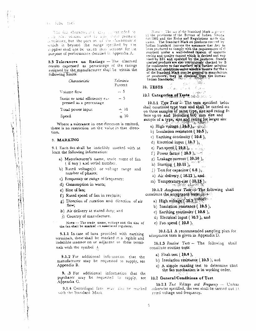
1 A Fan Ducted at Out let only
I - . 1
F A N TOTAI. PRESSURE
. iH Fan Ducted a t Out let and Inlet
9 . . EXTRACT FAN
FAN TOTAL \ PRESSWRE - u I d f C Fan Duciad a t :rile: bnly
FIG. 1 DIAGRAMMATIC IL&STRATIONS OF FAN PRESSURE DEFINITIONS
4. RATED VOLTAGE impeller assembly shall be securely b e d so that it does not loosen ir? o=c~,-: =ttcn.
4.1 The preferred rated voltages for centrifugal fans shall be 230 and 240 \t,. single-phase; and 16.4 Mounting - T h e means ~rovided for secur- 400 and 415 V, :3,pbast. ( s&TS : 585-1962. 1. ing the fan mounting or fan casing shall be :ach
. :.. ..:.+F .;.y :-2...-iTiL j7, :, ; :. : 2 as to providc a secure fixing. Where the &sing
5. RATED mE.Q&JENCY-: 7-r; . . , :
a 5,:+A-;.;l:.. : f . :. . .. . , c y : ::,, , ,: contains members to be c l m p c d against an
,&I The rated' 'frequ&cy %hall be -thd ptandard exterior wall, these shall be capable of being
frequency of 50 HZ:' - - .. scaled to prevent the ingress of rain-water at the point of attachment.
N b m -.Netieffheleh, f&is iaade far other freque- acid $hall be comidered to comply with the specifics- 6.5 Guards - Suitable designed guards shall be tion ~mvided they do ao in 811 other relevant r e u w t s . made available by b e manufacturer for
6 , DE/SIGN AND G - ~ L CONSTRUG on request and shall be fitted either to the inlet
TION . '+ ' ;-LC ! or the outlet or both, to prevent. acadental con-
f . ; : : , . - I . . tact with the rotating blades. T h e guards shall 6.1 Motor Enclosnre - The ' enclosure of the be securely attached and shall be adequately rigid fan motor shall, be of the totally enclosed type or to resist accidental contact with the b l i d e ~ . .%%%en SPDP. the guards are in two pieces, positive locking
arrangement to keep the two pieces together 6.2 Rotor '- ~h.l.ktjf8r'of ihe fan motor shall be be made, . . : . - u. ell-balanced. . . .
..,:i7:,, ::: ,. :i ,;3.:..-+, .:: :,;. ,
6.3 Blades :- shall b2;fkJd-with an impe- 6.6 Bearings - If necessary, the - manufacturer
f l e r c o n s i s ~ i n ~ of a of blades or vanes shall, on inquiry, furnish information about the made from metal or other suitable material. The of bearing and instructions for their proper
- . I . 1. ; ;,: ; . , .. ?;,;-.( ; lubrication ( see 9 .1 .2 ) . Proper types of beafii3
=Specjjjcarjon for vojrap and, i rehuency for sc trans- 5:'~ii:d be U C ~ i O ensure a reasonabie arnoznt o r mission 2nd distributioo systems ( -9vircd ). : ; lent opera t ion .
h a v e p : ~ ~ e ~ ~ v e electrical ins: : a ~ o n or be capable of k i n g earthed, A fan with protcciive electricai insularion may be of a l l - i n sv !a~cd constn!crior! or have either double insulation or reinforced insulation.
&1,1 In ebc case of fan!, ~nrendcd to be earthed, an c a r t h ~ n g ecrmLnal o ladqua te cg- - -- -m+g-capacirp mnv-y located and easily accessible shall be provided. I n the c m of fa fw use on k - p h a w , two 3cparatc e d b g ?Qmlnals lha4 tx provided.
6 3 C h p d t o t - p - Capacitors, !f a n y , shall be d y rcplaccable and piaced at s & c i c n t dutancc &am the w i n h g a so that their maximum work- ing wrnpxa tun is not ucccdcd Capacitors shall bc dcarly marked w i ~ h the maximum safe work- ing tcmpcrarurc, and the corresponding vdtage and capadtaxice. Capacitors shall comply with IS : 1709-1984..
7 - 4 Temperetare-= s --- The fan roc [ lie regulator ah& be tested at any cool cmperature not exceding 40°C, bct w
-ray be the value of thb tcmpcrature, the ssiblc temperature-riae when m c a ~ u r e d as bed In 1!J.13,2 shall not q c e e d t h e limlu ~ r i Table 1.
7. GENERAL AND SAFETY R E Q U W MENTS
9,l Protection Aga ins t Electric She& - In h e 'assembled fan, live parcs shall not be accessi- b k to tbe standard test finger ( s t c IS : 1401. 197O-t ). In h e case of a double insulated fair, both basically intulatcd par& and livc p a shall nor be accxaihle w the s t a o d ~ d : s i 6npc:. This rcquircmcnt is applicable for all pit icas in thc n d w.
7.2 Ekttric Lronladoa - The clcctric insula- tion of tbe fans shall bc adequate anhthc leakage m t in n o m d use shall not be cxccssivc.
SL PUT OX TZ.XZB;BATUBP-RI~, QC B !do. MOTOB oa ,---------,
Ramu~~ros Clase A Clm E C l ~ u B % . Iqru la . 'd~Lo- Inaula- a
w &a iim (1) (2) .- ,., 3 - 4 ) ( 5 )
I ) I ruulr td -A- 60 75 80 (
dl"n .$ motom
ii) Inrulrted win; 60 95 80 b, ifmy, I
7 2 1 When n?assd a c o r & n g to the method spfdfitd in 10.5, the insulation resistance shall n~tbc las tban2MD.
7.2.2 Lrakag: Gar& - Rcquircmcnts of the dcvant Indian Standards on moton shall apply. The lcakkge aurcnt which may flow from the live parts to the aoctssible parts and metal foil on external insulating material connected together shDLl not ucccd 300 PA (peak ), that is 210 ( rms ).
7.2.3 Thcrc shall be no breakdown of the i h t i o n when the fan is subjected to high -7.oltagc tcrt given in 10.3 or flash test ( 10.9 ),
wc c s c may be.
of regularw ( W i t h cpntb nuou r u e log on 'ray caaract )
s i ~ ) Regulatw r d - The tempernure-rte ,hall TL ltance unit no: reach ruch r d u e r t with cogti- that them ir a ,$ n w u rum-: injury to any b u m g hP On s y --.-'-I -v=tsu OTL a.cijwect coatact) - part* o f t h e ~egulator
iv) E x ~ w l d e - 49 ' rW 40 Th cen likely to be . touchbd
P
dur1n.S sarmal *a , . -, , l.
7% LnrPladng h h t e r i d ~ - Windings of fam r@aron ( where provided ) shall be insula-
ted with either Claw A, Class E or Claa B insulating matcriak which comply with the limiu of tunperam-+c spccificd in 7.4. These insulat- ing materials are detailed in IS : 1271-1985$.
*Specifica& for cepscircn for r iec t r ic fas moton ( & s i r r ~ i r i o r ).
$S-pz&caxioa ios ~ C C + + M ! ~ I ~ I I \ l e s t probag (j.:, ?-t%G-k?~a :.
!The rma l evzluatlm m i r l s i i ~ h i a r l u n o l +\.rt:ic.:,
iaxilaiioa j j i r i r T C D ~ J : ~
.L,? " 1
7.5 Pinfsb - All the sdacu of fan mo blades and regulator, if -any, @dl be of carros resisting material or &all & suitably and dura praectcd against A ... qpos iop~ fw spec& apph tiom , . . 3;?'p.'- .-+. 1 Let1' '
7.6.1 It is. n ~ t ,uspal for fans covercd by t specification to be provided with regulatc Howtvcr, if regulators arc required, this h a i l a matter of egrtcmeaat between Jlz p w k r B
the supplier,
7.6,2 Enclosures 3f the f2n regulators s r , b l l either of the ventilated typc oz h e ;<lai %clc?,ti t'JF

i I .. : 4.6.3 \Vhtre a regulator is provided with a i a cnso rc 2 i - ~ : a ~ ~ ; : : ~ t ~ ! ~ . ,dr.g~-rt-. cjf ~ I I ~ ~ I C ; : , 2.t. i i l
or not permanently connected across the speeds, or tcrminab, provision shall be made so t ha t NOTE -- 1 i1e n c e d for specifying l i m i u of noise
the capacitor is discharged when the r e p l a t o r is levi-ls ( acoustical . or t!>e Cans i s recognized. Wo%,ever, in the 'OFF' position. . , . i r has not been round possible to specify t h a e limits a (
present on account of: 7.6.4 The regulator handle or knob or push
aj dependency 3: these l i r n i i s on t h e a c t u a l Iwation buttons shall either be of insulating material or, of the fans, if of metal, shall be adequately insulated elcctri- b) lack of data on t h e acceptable noise levels for cally and thermally so that .temp~rature-rise different applicarioes, a n d &QX ambient is limited t@ 20°C. metallic c ) lack of agreed definition of noise level and method parts associated with it shall be protected from of evaluating t h e same accidental contact.
The criterion of noise level may, therefore, be 7.6.5 The regulator handle or $nab shall be SO subject an agreement \,etween <he rnan.Jac-
placed that i t may be safely, and conveniently :a,,, the purchaser. mhnipulatcd with definite positioning action. The handie or knob shall, be so designed, that it does B. PERFORMANCE REQUIREmmS not become loose iEi use,,,Thtl. 'Running' and 'OFF' p i t i o n s of &ti regida~i.$hdl,$e distinctly A h Delivery Test - This test shall be and ,-lealy mark& an& tb;e *djc+tor on the taxied out and calculations made in accordance operating handle or knob.sfial1 ee~~tly indicate 10.12. the ps i t ionof the regulator. 8.2 Fan C h a r a c t e r i s t i c s - Fan characteristic
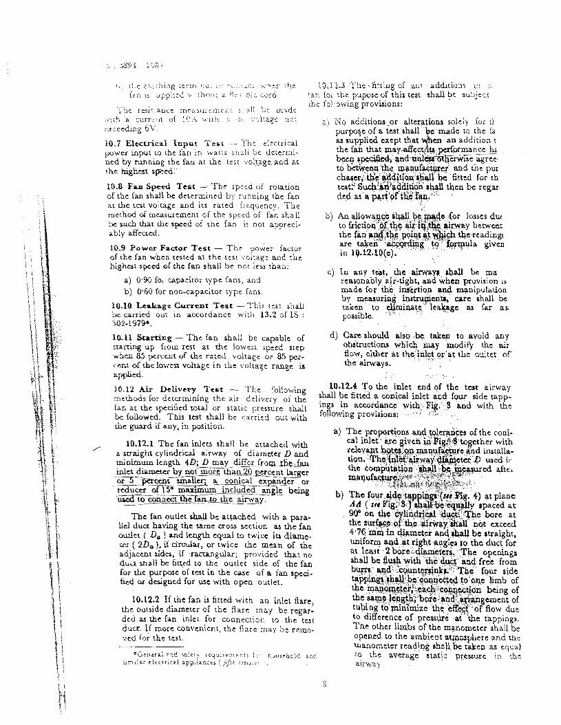
7.6.6 The regulators shall have mechanical curves shall be drawn after testing, considering stops for the regulator moving ccintact to prevent not less than :hree test points determining a short accidental contact with the metallic body of the part of the fan characteristic a t different inlet
tor in the event of forced overtravel of the volume flows and corresponding fan total or static pressure.
7.6.7 The mechanism of the regulator shall be A system resistance line shall also be drawn, so designed as to ensure Positive contact at each passing through the specified duty point such that running ~osit ion. In the case of inductance type the total or static prensurc: varip--, ::.i& :he square rcplator, it is cpctntia! that EG p i t i o n of rhe of the inlet volume flow ( ~ i ~ . 2 ). inductive winding should remain permanently short-circuited in any of the running positions. The n c s t probable operating point for the fan
shall be at the intersection of the fan characteri- 7'7 'nterchweabitiw -'The motor of the fan stic and the system resistance line. T h e difference of a particular size and model and its associated between the inlet volume flow at :he intersection reg~lator and set of blades shall be interchange- able mch that the Fr-,-,rmlEce & &; sn kiipi and the s ~ c l f i e d in le t ''dome "" ( % '''
duty point ) shall be recorded as the measure of within the limits of standard. departure of the fan from the specified perfor- 7.8 silent Operation - Precautions shall be mance. This value shall fall within the range ci taken in the maoufacturi of faris and regulators specified tolerances.
W (r
SYSTEM RESISTANCE 3 V) In
W 0: a -I " - d ! . C 0 C
2 Q I&
INLET VOLUME F L D ' ; ~
p : ? r ~ s s u : e Q,, = in let vo lume
-7
14:: 2 EXAMPLZ OF FAN <HARXCTERISTIT: CUXV ::;z r E S ~ PC;P I;2E, :!.:> C:JT~,<
< 1.' -, .
~ -:.~'
. , \ ~: I,
l:~.c !A:) c ~ ~ J ~ c T : ! i. C ~y.:., :- ;;. ;- I-: ,.j <- ( J , ;> , o 1 ; ; : ~ : voiuiric &:!;i :,: L : ! ~ . . ~ . : i i . ~ T C S S L . C
., i ~ f i i c i , j r i , , bur the porr ,3!i ~ j i : ' . c I J , ; ~ : B C I C ~ I S I C
~ r , . ~ i c h ;s bcyond \he range ieecihcd by ;e j:p$icr s h d not be r a , t n inti. s i coun t for ,?c p s p m c o l periorma.rrcc detailed i n Appendix A.
8 3 'JT~kmxtcer QZ.X Rseings - T h e observed results c x p ~ s x d as pcrccntage of the rarings
by chc m a m a n u f a c ~ ~ ~ r shall be wirhin thc followng Limits:
5 . j ~ ~ - ' r h ~ of the Standard Mark r gs.~;- i i 3:. r h r provisioas of the Bureau of Indian S ~ a n d a A c t 1986 and the R u l a a d Rtgulatiorur m r d e chi; ; u d e r . The Standard Mark 4n producu COY ?red by I ~ d i a n Standard conveys the o s w a n c e t h a t . h e y h~
' i , ' ~ ~ e BOW -,- 5 .. . . .4% ~c iQ.1 Catego+*:,~.$..T.q9:~Iii~ji i:.:.:. . ,,
Sratic or r o d &dcncy rx - - 5 p r d as a pc rccn tage
Total power input i- 10 - Spccd & 10
Wherc a tolcrancc in one direcc~on is omitted, rhae is no rcsuiction on ~ b c value in that direc- rioa
9 . MAFmING d) Electrical input ( 10.7 ); . . . . . . .
9.8 Each fan shall bc indelibly marked with at e) Fan s.p~~$&~~&,,,l$.,t:), ~. :: ;. :.;*.. 1- the following informarion: f ) Power factor ( 10.9 ); .-;+..:.
8 ) M~Q~&TA-cT'S - m e ; i r d d t ZZCC:: c.! fzz g). ~ t $ i r a ~ e - - ~ , r r e n t , j ' >P*H ), - - . , . , - ( if any ) u d scrial number; . . ? . . ,. . .
h! ~tartipg.(.l~.ii), < . .
b) or i'olcage and j ) Tcst,foy cap+citor ( 6.8 ),., numbcr of phascs;
k ) A~L delivery. !( 10.13 ),;and.. ,
c) Frcqucncy or rangc of frequency; d) coosumption in watts; m> Tem.pa-ItLiy- ( 14&1.3 .:\. .. ) ..:
. . . , *.,-?\; .<a;,j. ,=. . . ,.. :c... , .: .
e) Size of hq 10.1.2 ~c~cj&a<r: >,. ..-. _. ,fo~owing 8h.U f ) Rarcd sped of fan in revlmin; c o ~ s t i t u ~ &G .a.cqeg.~~:.k+?&$&~.+ . . .. 1.
-. .,; ,.,., :% , , ., ' ' -*:. :
g) Ei-&on of ronrion and direction of air a) High y q ! t ~ ~ : ( : . l O , ~ ~ ~ ~ . . -:, ,.-.. ,. . . : . i.T.2*'" flow; b) Insulation yr+tanc.b ( 10.5 );
h) Air delivery at stated duty; and C) Earthing 40ntbuity ( 10.6 ), j) Country of manufacture. d) ~lectricai'in~ut ( 10.7 ), and N- - T h e trade name, voltage and the size of e) Fan speed ( 19.8 )..
& Ian & d l be m u k e d t:n ozrxialed regulator.
10.1.2.1 A recommended sampling plan for 9.1.1 In caw: of fans provided with earthing atceptance tesrs is given in ~ ~ ~ d b D.
&=h, &ex shall be marked in a legible and inddible manner on or adjacent Lo these rermi- 10.1.3 Routine Tssb -- The FoblowiIig shd i rials Mi& the s y m h l I
3 constitute routine t q U :
9.1-2 For addiuorla! inio:rnation that the a) F l d test ( 10.4 ),
mrnufactvru may be rcqucrred to iuppiy, nee b) I " S ~ @ O ~ r./btpn&( 105 ), and Appc~dix B. c) A siFpie running t&r to determine that
thc fan mtcha+lir ia in working order. 9. 3 For additional information that the ..I , . ..
p e a s e r may be rcqursled supply, set i0.2 CaegarlConditions of Taet Append; C.
163.2.1 f i s t Voltage and f i b p m j --- Unl-5 9.1.4 Ccnrrifugai fans rns\ 21s.: bc ~ z ! - l - & ctB:r;:ioc spedScd, the i a c sbdi be r~-+.ed ou.7 i-!
...rich th:. S1ands.d M a r k s.=red voltage and f r c q u a q .

10 ,2 . i , l W h i n a rated voltage is indicarrd or, t h e name-plate, the t e s t shall be conducted at ! h ~ rated voltage. I f the fan is specified for tt:.o or more distinct rated voltages with three or mcjre suppiy terminals, the tests shall be carried out at :he most unfavourable voltage. In casc of doubt, the tests shall be carried out a t all voltages.
10.2.1.2 When a rated voltige range is indicated on the name-plate, the test shall be conducted at the mean of the upper and lower limits of thc range provided that 'the upper limit does not exceed the lower limit by more than 10 percent.
If the dpper limit exceeds this value, \he test shall be conducted at the voltage corresponding to either the upper limit or the lower limit which- ever is more unfavourable to the particular test.
10.2.1.3 Limits of voltags voriatiofi - The variation in the test voltage shall not exceed 5 1 percent of the test voltage during air delivery tests. While taking the current and watt read- ings during these tests, however, the voltage shall be maintained at the test voltage.
10.2.2 For a fan rated with a range of frequ- ency, the test shall be made at the rrequency which gives the most unfavourable results. Tole- rance o n frcql~ency shz!! be & 1 ppeicesit.
10.2.3 &mils of E~ror of Electrical Instruments - The ammeters, voltmeters and wattmeters used for type tests shall have a class index 0.5 or better [ see IS : 1248 ( Part 1 )-1983* 1, For routine and acceptance tests, instnunents of class index 2 may L. * vc usea.
10.3 High Voltage Test
10.3.1 The source of supply for high voltage test shall bc not less than 500 VA.
T- , ' , 1 , , l r ' rS
1 : Ur!. . . . , i i I tvc ~ ! A I t i :!rjd o r h e r ! :C!O 5' i r ? c i t . ~ . ! s , hle li;ctal parts
l i : .~i I S , [n.:ir tile funet~onal ,
: i ;c~~;:~:.c,n ) i n tile. case of d ~ l i b i e iilsulated morors
2 ) Bettveen rhe inacccssible 2 500 'Y'
metal parts and the body i that i s . over the supplemen- tary insulation ) in h e casc of double insulated motors
3 ) Betwcen live parts and body 4. CQO '! ( that is, over the reinforce-d insulation ) for relniorccd insulated motors
b) For reguiators ( where provided j Between the two terminals ! 500 V with the regulator in the 'OFF' position
10.3.4 At the end of one minute, the test voltage shall be removed and the insulation- resistance test conducted as in 10.5.
10.3.2 T h e high voltage test shall be applied to all ncw and cornpletcd fan motors in normal working conditions with all parts in place except the capacitoo which should be disconnected. As type test, this test should preferably be done immediately ,after .the temperature-rise test.
10.3.5 If this test is required to be repeated, the test voltage levels shall be reduced to 85 per- cent of the original value.
i0.4 mash T e s t - Every fan a d regulator shaii withstand the voltage 20 percent higher than that specified in 10.3.3 for one second when i t is applied instantaneously between the points speci- fied in 10.3.3.
10.4.1 Any other test similar to t he oze se= Eed iii 13.4 may be c a m e d out as a rout& test provided it wiU ensure the fan passing the high voltage test covered by 10.3.
. ~ . ,
gradually ~educed .
'S~ecif icat ion for direct acting indicating aoalog..~e ~ l e c t r i c z ! ze=:::izg i2 : i i ;~ tn i s and rheir accewries: Par! i Gtnp-al requirements ( sdcond rz~S'.;ion ).
lq.5 Insdadon Resistance Teat
10.5.1 Insulation resistance test shaU be cam4 out on fans and regulators immediately after conducting the high voltage or flash test, as the case may be.
10.5.2 The insulation resistance s h d be not lesg than 2 megohrm when tested with a dc voltage approximately 500 V applied between the points used for hi$ voltage test or flash test.
10.6 Earthing Continuity Test - For fans inttnded to be earthed, the resistance shall no: exceed 0:l ohm between any exposed metal parts, except the rotating parts supported by metal bearings, and
a ) the free end of the earthing conductor if the Can is fitted with a flexible cord, due allowance being made for the resistance of rhe earthins ccnductor of t h e flexible c ~ i d or
b J Lhc c>.f2.r~!r,g tc!cr-.!r1a: c. ,:c,: . L C [ : '-.her t.he :kG.i?.3 ' r hc . fitting of ari: additions cc t.i - . t.a.0 u upplied +lib(>!.: 2. -.:I. .o!i c u r d . !l.:i foi the puposc of this teat shall be subjc-t
cbc fcl:owing provisions: T'ht r&r.ancc rnezsl i rzmci . t i all be made . . ,
,+;ih a c . ~ ; : I I . of 10.4 \.'ich :- ?, . '.-51iage nor a ) No additiqns-or alterqtions mlely for :k r x c c d n g 6'G.
10.7 Elgcuical Input T e s t - 'The t l c c t r i c a l , p w e r input r;, rhe fan in waris sllzLl bc dcrermi- ntd by m i n g the fasl at rhc test v o l ~ ~ g e and as L h t h g k - S p C i d . ~-
10.8 Fan S W , Test -. T h e speed of rotation of thc fan shall bc dctermlccd by runn ing ehc fan at rhe t a t voltage and i t s ratcd frequency. T h e , .
m e d - d mea-~t~unenr of the sprrd of fm shall b) An d ~ w . ~ ~ ~ q . i ~ ~ . , & ~ ~ ~ e . : ( o r loss~s du tr wch b e rht s p e d of rhc fan is not appreci- to frictipq::@&t$c $LX iq&..ainuay b c n v m ab ly &cad. the fad w~$~%$;~&$@$~'hi& tbercading 10.9 Power Factor T e s t - T h e power factor are taken \a&yding'..~o +qula given
of the fan whcn tested at the tcsr ,voltage a n d t h e in lQ.12.10(c). highat speed of the fan shall be ncr less h a n :
c) ZB any tqt, the airwan, ahdl be ma a) 0.93 for apacitor type fans, and reasonably air-tight, and when provision 1s
b) 0.60 for noo-capacitor typc Cans. made for thk, ins'crtion +ad manipulation by mcqwipg ~QSQU$CR& care shall be
10.10 Leakage Current Test - T h i s rcst shall takcn , ta ,elinlinac le*ge as far a& bc carried ou: in accordance with 13.2 of IS : pss~ble . :-' ' . '
302-1979.
10.11 Srnrting - The fan &all be capable of d) @are should alilo ;be, takm to avoid any srarting up from r a t at thc lowest speed siep obsmctiom .whi+ m d f y tibt &; whcn 85 pcrcrnr of &c rz:ed -voirage or 85 p:- flow, titter a t the; . inlet . , :$,., ??'at t he d t e t o f
the airways. c s of hc!ows-i voMitzgc i n the voltagc range s a@d. , . ., , .
10.12 a- &Livery 'Test - T h c following 10.12.4 To.thc inlct end of the t a t airway m c h o d s for dcrumining the air delivery ol the shall be f i t ted a conical inlet and four side tapp- fu at the spcdfid or s tar ic pressure shall Lugs in acwrdancc , . with;. l?ig,:.S and with t h e
fouowrd. ~~i~ hall bc carried Gd; wiib f~!h+.;'ng Fi%iiiQns: --:"! :::- ~ ' ,- rhc guard if any, k p i t i o i i . a) The proportions and tolerahca of the coni-
10.12.1 T h c fan inlets shall be attached w i a cal inlet" w : g i v c A i*Pig,Y3+togethcr with 2 s r~a igh t cylindrical airway of diameter l> and ~ e l e v v ~ b@@l+~~,rnaqu,~.c:and installa- minimum length 40; D may differ from t f i c . , b tion. 'Thq:W$~&way>h,~ctei D used ir-
act diameter by n o t ' F r c a n 20 ucent Larger the computiitioft-: , .r;:w,.r+:a;5+i~;~:;. , ., ,'&alJ -.b$iP&ured z7+...,.. aftei 6 r Z Y j j g n 1 q m U c r i a c ~ n G T % i i ~ o r rnP9~hqyg.~~: .- ~. . . c~ : fe :%.&: .,q, 7,:;;:.-$.&.:j. ::::gyy7.-.: ,.; &urn of l Y ?"mum include^ being ufcd t--a&t the f an ro the a~rway. b) The foyr ..6jd%k@p u]&(:& -Rig. 4) at p1,ane
-. - AA ( 'st? Pig:;!J:f' ;., *b.*idy spaced at The fan outlet shall bc attachcd w i h a para-
$.' . 90' on th~'Cy~n,ddcal .:$U&~.~T&C bore at
Ild dua having rhc same moss section as the fan the sur&.~f :*$ :&rivay.stiall not exceed
cudct ( Do ) and length qua1 to twice iu diame 4.76. min in diameter andahall be straight, rrr ( 2 0 , ) , il circ;llar, or twice the mean OF the uniform sad, at right angles to thc duct, for a d w t sida, if ractangular; provided that no at l ~ t . 2 boje.r-d+mcfcrs,r:The opcilinge d ~ a shall bc f i u d to t h e outlce side of r hc fan ha l l bc flush %ith 'ihc&.@;"ind free from for thc purpose of t a t i n the casc of a fan speci- b ~ : tahhgbtrba,,b a n d ~ 2 ? ~ t w s i n k ~ . ~ ' ~ ! . - T b c ~ . .:: . s ., :.. four ide €id or dcsigncd lor use with open outlct. . . ,, ... ,_,, .,,, $i c,oqccfod-!oi?.ne limb of
the %Ko&$t&:.~a.& j~co$cctj6n being of 10.12.2 If the fan is fitted with an inlet flare, ~ g $ l ~ ? g t h ; . . b ~ r c l + d ~ + ' ~ ~ c r a e n t of
h e ou&de diamctcr of rhc flare may be rcgar- tubing to piittPmiic.thc ;effait .of flow due dcd as the fan inlet for connection to the test to diffcrcnce of pressure . ac'the tappings. ducr If more convenient, the flare rr lay be remo- The other limbs of the qanoynetcr shall be vcd Cor rhc rest. opened to the anrbicnr stgisp'lcre and ~e
mwome:er reading h ~ l l bc t&eu as equal * t i e n e r d ~ c c i =re:> i e q u i r ~ r n t n : ~ i c h21?r t t e !d a i ; ~ the average static PteSWc in rtrc
i i n i l r r e l e c ~ r i c z i a p p ~ i r n c t r (,<Ji, : rc r i .o : . airway,

5,' I I \THE JUNCUOH EETWEEN 6 0 . ~ 0 ~ ~ LI.C --- SD M I P - -A 0 ~ 1 ~ - P A R A L L E L PIPE S H A L L BE S h t 3 0 l h 4ND
0 , 6RIf FROM RIDGES
h 0 EXlFRNCL OBSTRUC~ION 10 T H E F R F E M G V E U E N T O F AR E N T E R I N G IH;;NLET 1s PERMITTED WITHIN THIS R E G I O N , i H E R E MUST BE NO EXTRAN- EOUS AIR CURRENTS m THE vluccnv OF- THE WLET
, 2 - * c . - . . - . - . - ,. . . * r z I ~ : L , L j F : ;C,.I~ECTI~!: FOR k O C K SIT)? '1 ; P ? : N c Ti\ TEST L)i? .i .;KD ~::.:iShZi:Tii)\;
7; '.,I..:.xO!>:i.T:,R FOR INL: ' . ; . : -!o~ 6' A\:EXAGE 5:: ,3, T x ~ n l l c b ' e:;?. BL.cE.:

:. , . . . . . , ,.:, -~ ; ., !i. ! & ~ ~ : . < ;:' , . . .
. . . .. . ., . , .. . . . - . . . . - . . r. i','.; ,..-,.-. . . > - ..>\.;,a. = r : < r ; y :":it,:.:> ,,:,...:: : . -Ls[; ; [ le, j L3 .. ; 7,!,:~; , ,>. r.! 5 : . . - , ,-. ,., . , .. . , . ,. ,-\.,.. :,: h r : ,
.,::,,>\,.e iz ::;: = , ~ , . .., , . . . .
+ .Li, ~ r : 1 ~ i i l c 2. r,;: Keynolor V, .: z ~ i ~ ~ i . : i .... -1 . . . :' , 3 u u v ~ n !i, i~iJ O!-:i: 2nd ci,;;:;!: rh- cocci. ,?;cri: ,,IC f ~ : s . - b ~ ; i ~ ~ : : !; iJ 27t, :~!!(!, ( : O V < ~
10.12.0 '1 kit.;.,: I:: ., i . . i . i . p r t s u r s la ta i
ti,t n,ajur;t.b. c,f c i .2 cGLs , i\~!~ :.::: t h e 2 . r k;?; c>12i3i!;e(j by :i!:-~.<,., < 1.i-it screen L. adc '?.,< - iri c,, ' :.L .k
add~rio!~rii s c r t t n s i r t :@,: ri l i t duct . If a rini - .>Ic ~-,!:I:?s ?e: k.!-~il-> : > l . l ~ ~ ~ i - i -
cail) I c s i t h a n 16 t in !c j r n r airway sccurei i inside t h t :r,r d i r w a y to supporr
diyimeter :r i r n r t r s s , cheu t!ie ciii.15iienr of s r r c r r , , or when a r i ng is usrd to s t i f i n :lic pc dicchargc shall be r aken a p ~ r s p r i a : ~ ~ " h c phery G:' the Fabric o r o:hcr screen, the rac
Rli;nolds rigmbcr given in 'Tabit 2. rhickness o i the r j n z :ha!! n s i be grea te r r'n _-.>-I=
BilOo (. sec Fig1~5 j. ~ ~ - . -- . . . , .
TABLE':! DISCHARGE COEFFICIENTS FOR 10.12.7 At plane BB, distant 2 D dmnstrca REYNOLDS NUMBER ( Re ) from r h e resistance scrceri, therc shall be four s i
. . [ Cloxsr 10.12.+(c) ] tappings, similar to those in planc A A , and co nected to che low prrwure limb of a monomete
RETXCI.DS 20 W', a 000, 60 00.j, 100 &C other limb being connected to the ambicl N c l i n g s ( 8 ; ) 2m OCjg , 3W MO G O O ~ pressure in the vicirity of the fan discharge.
9 1 s c a a ~ o s 0,930, 0'940, 0'945, 0'953, 0,967, COBFPICLE.YT, CD 0-973, 0.975 10.128 'l'hc volume per unit time at plane 1 ' .A roniclrl inlet rhall nor be ued at Reynolon number, shall b? computed by using formula ( 1 )
len c h n 20 000. mrrcctcd to fan inlct conditions for any chr .) ..- in the air density bctwccn plane A A and thc . ~ r
lntcrmediatc valucs of Co may be obtained by inlet BB. Linear intcrpalation. 10.12.9 All tcmpcratucs in the inlet LL
Thc Reynolds number for standard air is given be taken by placing the tllermomcty 23.58 Q its probe inside the airway ncar thc section L.
by RE - -7 ~ n g thenotation of 10.12-10 The inlet volume compiled ah& thcn be use3
... &ad my be tdcn to dctumiac [he cocfici- to calculate the vtlociiy pres'ure at plane BE --
en4 of didarsc ,,,i& negligibic error for d! using f omda t (2) and (3) . For thc y~rposc of this. nonniii vadationr in ambient ~ f i & i i o n s . :at the algebraic s u n ! with the nlgn rcvcrsed j
of thc static pre-qqe at b e BB, and the: velo- 10.12.5 A m l t a n u comprising n acrecn hav- city p m ~ at plwe ~1, plus a Lietion allow-
ing c v c d y apawd apcrturc of unilonn Gze, not ance for dl t a t ducting downstream o f p l m c BB, esccdirrg 0120 should be fitted at a distance D in accordance with formula (5) shall be takcn from ihe commencement of rhe cylindrical portion ar thc fa total prtssu&.
~. i . ., . ..: -- . . . ..?
1.:-
{ i I \ 1 i-
! I
i i : i
A M E T H O 3 OF SUPPORTI?,~? . . ~ 3 t Wai E-SChcif;
:. .. i - lo . ; R; ' .z . . ; ' :ce i~~i ;7 BO? 4 . j ~ DE; ~ye r : . ; T E j ~
I ! ! ()

10.12.IQ ,Zormu!ae c.2 ( .-,ir;u::::io~i o j Rfic~uii's she following f o r m u l a . ibt ,>u!c! )jt csed lor i h c computation of rwults si ~ h c J.PSIS laid d o i v ~ :?i 10.12:
a ) inlct volume per i : 11' 300 C, J unit time -
where &, = mfficicnt of dircharge, B - diamctcr of air- iay In metres,
L I P D diffmcnce beew .en ambicnt prc- ssurr: in the vlrlnity ol' the inlet and the avcrafe pressure at the sidc tappings at plane A A in mrn HIO, and
Wt = weight of air i r airway at the test temperature to in kg/ma.
b) Ncight ph. unit volum : of atmospheric air at test Section
~ h i c h may be very closcl~ approximatcd as
[ taking 1.205 kg/rnB ( approximatcd to 1.2 Enima 1 is the weiglbt crf :t&yd=,-d air ;it ~ n a n LV and 765 m a HE 1. where 8 - barometric r :essu~z i n mm Hg at
.he time of t.st, and
p , g= .tatic pressSu : in mm HaO.
c\ Vclocitv of air at a I oint V
d) Averagc "docity o air in the airway Y 1
c- / /
Q = - ln/h A ...... (4)
whcre A is the a rca of z.ir:ray 'in square metres.
e) Friction loss in airwa . P I
10.13 Temperature-Wise T e s t
10.1 3.1 A i c a ~ u r r m r n r o/ Cod~ng ,411 Tcmptraturc During Tcs t~ - T h e cooling air ternpcracurc shail bc mtasured by means of s e v c r ~ ! rhcrmomercn laced a t different points a r o l ~ n d rhc fan motor at a distance of 1 to 2 m and protectcd from all heat radiations and extraneous draughts. The: thermometcn uscd for t h i s test shall kx accurate ro * O.j0C,
T h e valuc to be adopted for the temperature cf the cooling air during a test shall bc the mcan oE t h e readings of t he thermometcrs tahcn at equal intcrvais of t ime during the last quarter 'of the duration of the test.
10.13.2 Measuremtnt of Trrn)trohrrc-hisc - Thc tempcrat ]re-rise measurements shall be m i e d out by thl mcthod indicatcd in Tablc I , immcdi- ately aftcr the air delivery test or aftcr thc fan has been run long enougli to ensurc that the tcm- peraturc--ise has rcachcd a stcady state using the following procedure.
llrd!3.?.! Air iemperature-riscs to be mca- iursd b) thermometer mcthod [ ircms (iii) and ( iv) of Table I ) ] jhall b e taken a t thc hottest a ,ccssibIe surface o: the parts, as also on thc parts wnich a!.e likely to cause injury ro any adjacent in;.l.lating materiai.
in 7 9 n rr m3 A v . ~ ~ . ~ . ~ L ne mcthod of measurernext oi
tcrnyxature-risc by change in resistance is given below.
T h c temperaturc-rise !, - t , ( Tor copper winding? 1 mav be obtained from the ratio ol the " ,
t -+ 235 R, - - rcsistanc s by the formula L- - t , + 235 K ,
R I = resistance of the windings a t tem- peraturc I , ( O C ) a t the end ol t he rest, and
Ri = initial resistance of the w+dings a' temperature ti ( OC ).
From th above, the hoe temperature ( 1 , ) may bc expl :ssed as:

hlETMOD OF CALCULATION O F EFFICIENCY
k-1. T h c performance 71 t h e fan ar a sr,pulat& air delivery, Q and fan toral pressure Pt shall be cxprcsscd by rhc 'total eficiency' 7 , which may be expressed as the r abo of alr power ( total ) Pt,,,l ro the shaft power PshBft
the air power j toral j may be obtained from r!:e fgrmula:
Pt,,,, - 2.725 i< 1 0 - 3 \, /, Q X Pt x KD watts ...... ( 7 )
K, is t h e compressibiliry coefficient hayiing a value of ~ in i ty for fan static presnure nor exceeding 255 mm H,O under normal armospilcric condttion. Ar higher pressures, h', should be decrrmi- zed by referrncr :c Fiq, 6, caic)c!ztlng the pressure ratio by means of the formula given below:
The value of r may be taker! as I . ? atmospheric air.
Pressure ratio ( p ) ( for exhausti cozditions which apply to te.: meih.od desc bed in l.V.12 ) iS given by
u , n g the notations of 10.12.10(bj.
T h e shaft power, P shall be obtaitl for the purpose of this specification f r o a r , ~ following relation:
' sbait = [ P~ - ( fixed losses + coppr; losscs + stray load losses ) watts .... . ( L Q
PL is the p w e r input to the motor .c!iti the fan coupled to the motcr and run a t rated duty and speed in :.;atts.
7 1 -- The fixed losses and copper losscs shali lie calculated in accordance ..with the derails given
-- ... . . . (8) in IS :. 4889-1968*:v.T&e i+;$jpei lo;;ss shaii b e i p - 1 \
I \ ? - ' ! calc+ted on the corre-s@nding current a t the duty point bF. the fai\;:LI:he stray load loss is assumed t* be 0!$ p,qcmt of the shaft power.
= iat io of specific heat at constant pre- . <!;..;<;:, r . .> ;::e:G ! + :
s u r e specific head a t constant bob de;e~q-lmlnatiio of efficiency cf rot=til1? vdume . electricnl machines. ,
. . ' . .~ . . . r 5 . '.. ?> ' - .- :? & . .
I @ l . i
& I , T h e c~llowing additional information in positLons, rer,pxt of an ckctr ic cenmfugai fan shal! bc class of insulation, supplied by the manufacturm QE r q u e s t : el Type of bearings,
a) P o w a factor,
b) N u m k of blader,
f ) Instructions for lubrication of m g s , g) Condenser n~lt;e ( in c ~ w of kagle-pha:
ians ), and
$. ADDITIONAL INFORMATION TO BE SUPPLlED BY THE PURCHASER
@-I. Thc following information in respect of an C) Air delivery at stated duty; cltccic centrifugal fan shall bc supplied by the d ) Nature of & or gases; purchaser on rcqucst:
e) Atmosphciic conditions; ,. . a j ~ I Z C ;
,' '1 2 bj Electric supply details;
T
i ) Altitude of the place w h e n the fan k to De installed; and
g j i.Vhethcr g u v d s arc q & d .
A P P E N D I X D ( Clause 10.1.2.1 )
i '( i RECOMMENDED SAMPLING PLAM * + i>
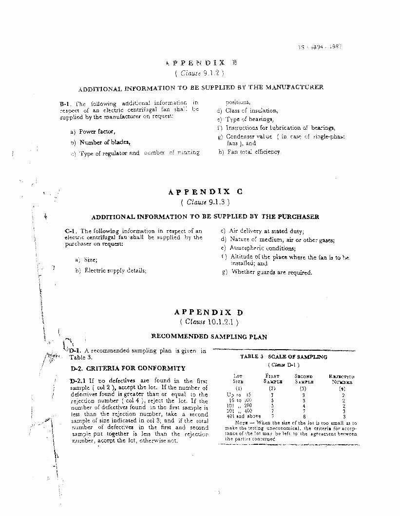
, %.%l. A rccommcndcd sampliag plan 1s given in jP3' Table 3. TABLe 3 SCALE OF SAMPLING ; .<
D-2. GRITEXIA FOR CONFORMITY
j -2.1 If no defectives ' are found in ehe first ; samplc ( cot 2 ), accept h.t lot. If the number of I' defective found ia greater than or equal to the
rr;cction number ( col 4 ) , rcject the lot. Zf the number of dcfcctivu found in the first sample is
i : 1 s than the rzjection number, take a second , : i / \ sample of size indicated in cal 3; and if the total
number of dcfcctivcs in the first and second ' 5 sample put tdgethcr is l a s than the r e j c c t i o ~
, , i numbcr, accept t he iot, othcrwisc not. 1.
LOT FIRFJT S E C O ~ RxJxc-nctr S I Z E S A ~ L B SAMPLE Nmrahs
(1) (2 ) (3) (4) Up 10 15 3 3 2
16 to 100 5 3 2 101 ,, 200 5 4 2 201 ,, 400 7 7 3 401 and a b n e 7 a 3
NOTE - When the r i z e of the lot u roo m a l l ;u to m a k e the tertlng uneconomic~l , ;be criteria for acccp- rance or \be lo t may be lefr to the agreement between the part1cs conctrned
--- -~ - -------L- --.-

&I. The lolloviing z.ddiilona1 information i:-1 positions, respect of an ekctric centrifugal fan hall be d) class of insu;atio8, -sxF:;litd by ehe manuficiurer on rqumt : 2 ) . Type of bcaringa,
a) Power f-, I ) Instructions for lubrication of bearbe g j Condense: d u e ( in tax cf . i n g l ~ p k ~ . ~
. ,
b) N u m k d b u m , izns ), and ,
. .
. ; ;:) T w Of p + t ~ ~ j d , :~LEC'C+Z tf ~ i ~ A i l 2 hj Fat total cffidi-my,, , s
A P P E N D I X C ( Clause 9-1.3 )
L T ~ ~ D r n f 3 N k . L M F O W T I O N '9'0 BE SUPPLIED BY THE . W R , C W B
I
el. ?!LC following inforrnat~on in respect of an c) Air dclivery at stated duty; clcct-!c ccntrifugd fan sha!i be supplied by the d) Nature of medium, air or purchaser on request:
e) Atmospheric, c o i i d i ~ ~ ;
i ! b Llcctric supply details; r
f ) Altitude of the place where the f a bs to & installed; and
g j Whether are qGd.
=. RECOMMEKDED SAMPLING P W 3 >, c'&l. A recornended sampling plan is given in -'---------- .. .-
TabLe 3. TABLE 3 sC& OF SMIPL$PIG
D-2. CRITERIA FOR CONFORMITY ( C k a ~ # Dl)
LOT FIRST S x c o m s 2 . 1 Tf no defectives are found in the first
RE... '11vn SIZE S A ~ L E SAXPLI N n m m
sanplc ( col 2 ), h~cept SC lot. If the number of (1) ( 2 ) (3) ( 4 ) , , \.,
defectives found is grcatm than or equal to the L'p to I S 3 3 2 rejection number ( co1 4 ) , rcject the lot. Pf the 16 t o ]DO 5 3 2 number of dcfcctives found in the first sample is 1 0 1 ,, 200 5 4
7 2
201 ,, 400 7 less t h m the rejection number, take a second ,401 a n d ab,se 7 3 8 sample of size indicated in col 3; and if the total
3 NOTE - When- the size of the lo1 is roo smdl ae to
numbs of defcctiva in the first and second make the testing uneconomic~~l , %be criteria, for s c r c p sample put together is less than thc rejectiop t a a c e o r t h e lor may be left t o the agpeenec : bt-ween
~ u m b t r , acccpt tht lot, otherwise not. ih2 ~ a r t i c ~ concerred.
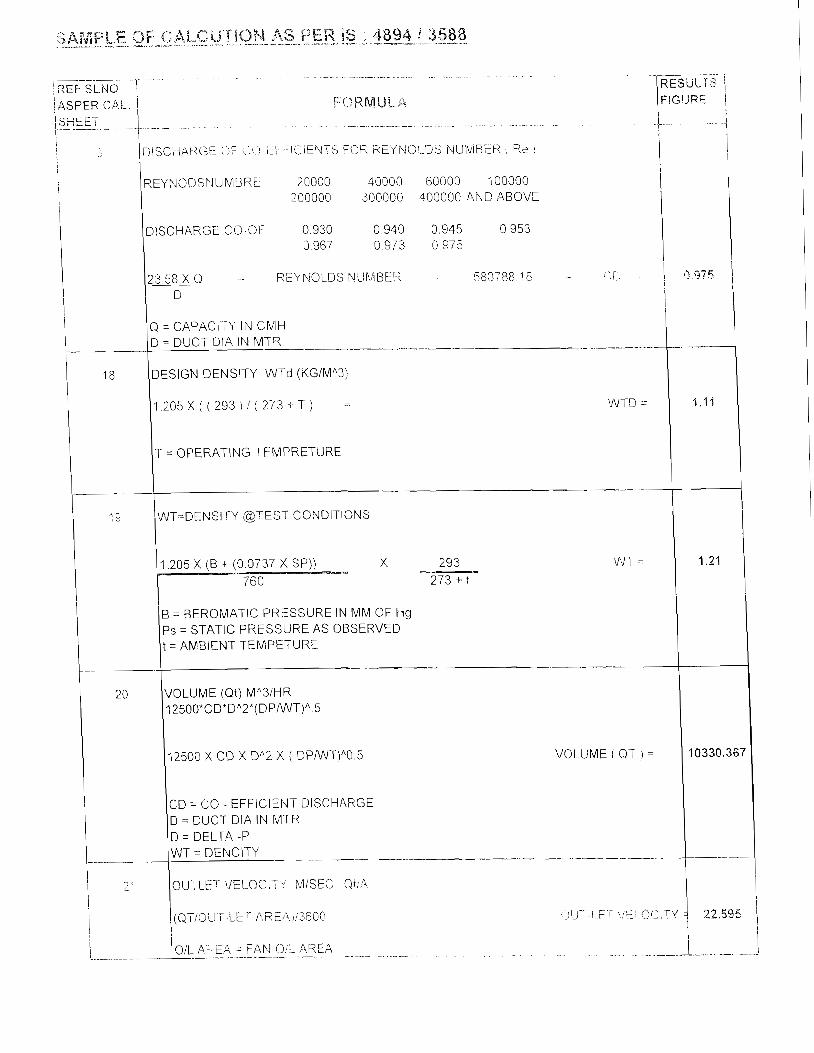
REYWODSNUMBRE 20000 40000 60000 100000 200000 300000 400000 AND ABOVE
DISCHARGE cO~OF 0.930 0.940 0.945 0 953 0 967 0.973 0.975
REYNOLDS N~J[\ASER - 580788 18 - $'r
I
18
Q = CAPACITY IN ClVlH D = DUCT D!A IN MTR -- - - - -- - - - - -- - - - -
DESIGN DENSITY WTd (KGIMA3)
1 2 0 5 X i ( 2 9 3 i ; ( 2 7 3 + T ) = WTD ;-
T = OPERATING TEMPRETURE
r-- 7- --, I
1.21
4 0330.367
! '19 IWT=DENSITY @TEST CONSITIONS I
X 293 WT = - 273 + t
I--. WT = DENCITY - -- -- -- ."
1 2' OUTLET \/ELOCl"-' hliSEC Uii4 i
20
I
8 = BEROMATIC PRESSURE IN MM OF Hg Ps = STATIC PRESSURE AS OBSERVED t = AMBIENT TEMPETURE
-
VOLUME (Qt) MA31HR 1 2500*CD*DA2*(DPiWT)/' 5
I2500 X CD X DA2 X i DPIWT)/'O 5 VOLUME ( QT I =
CD = CO - EFFICIENT DISCHA2GE D = DUCT DIA IN MTR D = DELTA -P

I i i [ \ ) ! . ~ : i~ / f -~~( , ,~ ,.,.! ; y !',!l'i { \< ! (Jii;i,i, i I i i i
\ I
, . - ~ [ \j c:, I- ;, j k!l k- , ( , . j [ ! r ,-,, : , :~ 1 ; 1,; - 1 f 1 ;A ,L !-i f ,, 1 ';?,I , b : l I ' l l T T . . , ! i , I , _. ,-;,:,,r', I )79752,>::,,: 1
I 1 1 ! i
(I!L .4RE$. - 1.L ~ ,A.REA i
+- '-. ~... . ~ . . . . -
I .. ~. ..;
. . 1, ., .. ~ . !VFar = TPoi MM
I
I I
1 ((OUT--LET '~./ELOCll '~' j"2/19.6)'WT \,/pet -
I :3?.;
WT = DENCITY
. - - ---
I j
)(INLET " E L g i T y !6000),h,2 >< \A! i 'Jpi = i
I i 30.08 1
i I .-~ r25 2 6
TPi=(Vpi - SPi) MM.Wg
(Vpi - Spl) VIM Wg Tpi =
- .- - -- - - -
FTPT=TPot-TPi MM.Wg
1 -334.9]
i , 1 \Ng 366.45
-
MOTOR OiP Mi"MEFFoh(KW) iMo)
18.5472 1 INPUT KW X MOTOR EFF. MOTOR PO\S\IER = MO =
4 - 4 10330.367 1
!
2 8
I 1 \ I . . - _____
29
1 ! \Oil AREA = FAN (>!L AREA 1
I 8q341472 i
i I 1 +- - - - - ~ - . ~ . .- -. -4 !
INPUT :<W = AS OBSERVED W1 + W2
RATED VOLUME (Q) MA3/HR
VOLUME (OT) MA31Hr X ( DESIGN RPM 1 RATED RQM! M A 3 i Hr = Q
--
RATED OIL VELOCITY QIA (IVIIHR)
RATED \JOLUME M"3 I Hr ! OUT LET AREA (3iL VELOCITY -.
i \!:<,AT: ~s \;;;I-. ',;ff; ,~;;,, '~: i.:,",[',c , . . ,, '/ ' .,,. t , 1 1 ~ ~ . . - . t . , 1 23,:;>5:\5.8
-. I
j ! ! 1
~ . ~ ~.~ . ~ . ~ ~ - . . . . .~~ .- . . .. . ...+ .
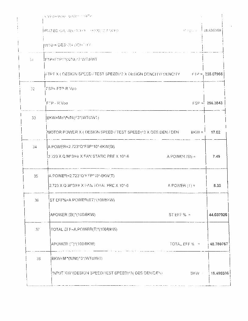
I FTP=FTPI ' i i\l:hBt, '?'WTd/Wl~
I 1 TES1 SPEEDY2 X DESIGN DENClTYi DENCITY
-- -. . -. - ~-
FSP= FTP--R ,/pc; i
i iFTP - R.ilpo
..... -. - -- .- . -. . .-. . -- -- -
B K W = M O * ( N ~ N ~ ) ~ ~ ' ( W T ~ ~ V L ' T )
X DES.DEN I DEN - . . -.
A.POWERz2 723"QkFSP'10"-6KW(St)
2.723 X Q MA31Hr X FAN STATIC PRE X 10"-6 A POWER /St) = 1 7.49
-- - --
A PG;.;?iER (T) =
1 I
i I 44.037026,
-
48.780767
I---- I
36
37
-. -. . - - - -
38
ST EFF%=A.POWER(ST)*(IOOISKW)
APOWER (St)*(l@OiBKW) ST EFF '10 =
TOTAL EFF=A.POWER(T)*(1001BKW)
APOWER (T)*(I 001BKW) TOTAL EFF '/r =
~ - - -- --
BKW=MI"(NIN~)"~ '(WTdlWT)
I INPUT KWZ(DESIGN SPEEDiTEST SPEED)"3( UES CEhliDEh;i RMW - 38.495506
I I - - --.- . - - . - -. .- .- .. . . ..~. . - . . . .. .i.._ i
c, = a(j;; j ,-,;:, . .
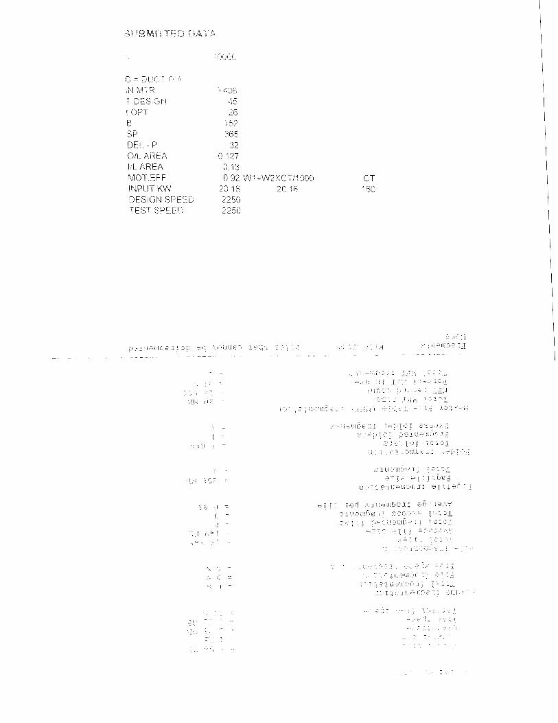
ib! Wll-R I OESiGpLi i OPT B SP DEL. - P OIL AREA I/L AREA MOTEFF INPUT KW DESIGN SFEEE TEST SPEE'J
,~ ,- I:,,:, (I =
y = ( 1 =
4 - i ,i, 1- 1 7
.J _, ., ,

AMS TEMP AlVlB TEP X 9 = 5
EXAMPLE
AMBTEMP= 25 2 5 x 9 : 45 i- 32 = 77-C Fht 5
273 + OPERATING TEMPERATUE X NMr'31HR
27 3
EXAMPLE :
273 + 50 X 600CO = 70989 CMH 273
CBNVERSON OF CT RATIO
IN C T. COWIUECTION ON
CONNECTION HAS TO BE DORE ! 5
EXAMPLE 5 0 C T I 5 = 10 10 IS AMP RATIO CT = 80 I0 X WATT METER STRIP = 8 = 80 I X = 1 0
CBNVERSON OF PASCAL BN MM