Embed Size (px)
Citation preview

Disclosure to Promote the Right To Information
Whereas the Parliament of India has set out to provide a practical regime of right to information for citizens to secure access to information under the control of public authorities, in order to promote transparency and accountability in the working of every public authority, and whereas the attached publication of the Bureau of Indian Standards is of particular interest to the public, particularly disadvantaged communities and those engaged in the pursuit of education and knowledge, the attached public safety standard is made available to promote the timely dissemination of this information in an accurate manner to the public.
इंटरनेट मानक
“!ान $ एक न' भारत का +नम-ण”Satyanarayan Gangaram Pitroda
“Invent a New India Using Knowledge”
“प0रा1 को छोड न' 5 तरफ”Jawaharlal Nehru
“Step Out From the Old to the New”
“जान1 का अ+धकार, जी1 का अ+धकार”Mazdoor Kisan Shakti Sangathan
“The Right to Information, The Right to Live”
“!ान एक ऐसा खजाना > जो कभी च0राया नहB जा सकता है”Bhartṛhari—Nītiśatakam
“Knowledge is such a treasure which cannot be stolen”
“Invent a New India Using Knowledge”
है”ह”ह
IS 2026-4 (1977): Power transformers, Part 4: Terminalmarking,tappings and connections [ETD 16: Transformers]


© BIS 2003
B U R E A U O F I N D I A N S T A N D A R D SMANAK BHAVAN, 9 BAHADUR SHAH ZAFAR MARG
NEW DELHI 110002
IS : 2026 (Part IV) - 1977(Reaffirmed 2001)
Edition 2.2(1993-09)
Price Group 7
Indian StandardSPECIFICATION FOR
POWER TRANSFORMERS
PART IV TERMINAL MARKINGS, TAPPINGSAND CONNECTIONS
( First Revision )(Incorporating Amendment Nos. 1 & 2)
UDC 621.314.222.6 : 621.315.684 - 777

AMENDMENT NO. 2 SEPTEMBER 1993 TO
IS 2026 ( Part 4 ) : 1977 SPECIFICATION FOR POWER TRANSFORMERS
PART 4 TERMINAL MARKING, TAPPINGS AND CONNECTIONS
( First Revision )
(Page 8, Fig. 3b) - Substitute the following for the existing:
1.1
i ’ 3
4 EC 5
6
7
o_o 2.1
(ETD 16) Reprography Unit, BIS, New Delhi, India

AMENDMENT.NO, 1 3FCEMBER 1984
TO
IS:2026(Part 4).1977 SPECIFICATION FOR POWER TRANSFORMERS
PART 4 TERMTYAL MARKINGS, TAPPIVGS AVD CONNECTIOYS
(First Revision)
(Pugs 12, clause 3,l.C) - Substitute the following for the existing clause:
“3.1.6 Requirements Related to Temperature- Rise (Gurantees and Tests.) - Temperature-rise limit values are applicable to the tapping position as specified in 3.4 of IS:2026(Part 2) 1977 *Specification for power transformers, Part 2 Temperature-rise'. Except in such cases where agreed to between the purchaser and the supplier, the temperature-rise test need be carried out on one tapping only, chosen in accordance with 3,4 of 1s:2026 (Part 2).1977,"
clause 3.2.2.2, Note 2) -
(ETDC 16)
Printed at Dee Kay Printers. New Delhi, India

IS : 2026 (Part IV) - 1977
© BIS 2003
BUREAU OF INDIAN STANDARDS
This publication is protected under the Indian Copyright Act (XIV of 1957) andreproduction in whole or in part by any means except with written permission of thepublisher shall be deemed to be an infringement of copyright under the said Act.
Indian StandardSPECIFICATION FOR
POWER TRANSFORMERSPART IV TERMINAL MARKINGS, TAPPINGS
AND CONNECTIONS
( First Revision )Transformer Sectional Committee, ETDC 16
ChairmanSHRI U. K. PATWARDHAN
Prayog Electricals Pvt Ltd, Bombay
Members RepresentingSHRI M. A. SHARIFF Karnataka Electricity Board, Bangalore
SHRI B. C. ALVA ( Alternate )SHRI S. AMMEERJAN Bharat Heavy Electricals Ltd (R&D Unit), BhopalSHRI N. S. S. AROKIASWAMY Tamil Nadu Electricity Board, Madras
SHRI M. K. SUNDARARAJAN ( Alternate )SHRI B. G. BHAKEY Kirloskar Electric Co Ltd, Bangalore
DR B. N. JAYARAM ( Alternate )SHRI A. V. BHEEMARAU Gujarat Electricity Board, Vadodara
SHRI J. S. IYER ( Alternate )SHRI S. D. CHOTRANEY Bombay Electric Supply and Transport Undertaking,
BombaySHRI Y. K. PALVANKAR ( Alternate )
DIRECTOR (TRANSMISSION) Central Electricity Authority, New DelhiDEPUTY DIRECTOR (TRANSMISSION) ( Alternate )
SHRI T. K. GHOSE Calcutta Electric Supply Corporation Ltd, CalcuttaSHRI P. K. BHATTACHARJEE ( Alternate )
JOINT DIRECTOR (SUB-STATION) Research, Designs and Standards Organization(Ministry of Railways), Lucknow
DEPUTY DIRECTOR STANDARDS (ELECTRICAL) ( Alternate )
SHRI J. K. KHANNA Directorate General of Supplies and Disposals(Inspection Wing), New Delhi
SHRI K. L. GARG ( Alternate )SHRI B. S. KOCHAR Rural Electrification Corporation Ltd, New Delhi
SHRI R. D. JAIN ( Alternate )SHRI J. R. MAHAJAN Indian Electrical Manufacturer’s Association,
BombaySHRI P. K. PHILIP ( Alternate )
( Continued on page 2 )

IS : 2026 (Part IV) - 1977
2
( Continued from page 1 )
Members RepresentingSHRI D. B. MEHTA Tata Hydro-Electric Power Supply Co Ltd, Bombay
SHRI R. CHANDRAMOULI ( Alternate )SHRI D. V. NARKE Bharat Heavy Electricals Ltd, Bhopal
SHRI ISHWAR CHANDRA ( Alternate I )SHRI PREM CHAND ( Alternate II )
SHRI I. S. PATEL Hindustan Brown Boveri Ltd, BombaySHRI V. N. PRAHLAD National Electrical Industries Ltd, Bhopal
SHRI A. G. GURJAR ( Alternate )SHRI K. N. RAMASWAMY Directorate General of Technical Development,
New DelhiSHRI S. K. PALHAN ( Alternate )
SHRI CHANDRA K. ROHATGI Pradip Lamp Works, PatnaSHRI D. P. SAHGAL Siemens India Ltd, Bombay
SHRI A. R. SALVI ( Alternate )SHRI I. C. SANGAR Delhi Electric Supply Undertaking, New Delhi
SHRI R. C. KHANNA ( Alternate )SHRI K. G. SHANMUKHAPPA NGEF Ltd, Bangalore
SHRI P. S. RAMAN ( Alternate )SUPERINTENDING ENGINEER
(OPERATION)Andhra Pradesh State Electricity Department
(Electricity Projects and Board), HyderabadSUPERINTENDING ENGINEER TECHNICAL
(PROJECTS) ( Alternate )SHRI C. R. VARIER Crompton Greaves Ltd, Bombay
SHRI S. V. MANERIKAR ( Alternate )SHRI S. P. SACHDEV,
Director (Elec tech)Director General, ISI ( Ex-officio Member )
SecretarySHRI VIJAI
Deputy Director (Elec tech), ISI
Panel for Revision of IS : 2026 Specification for Power Transformers, ETDC 16 : P6
SHRI S. V. MANERIKAR Crompton Greaves Ltd, BombaySHRI D. V. NARKE Bharat Heavy Electricals Ltd, Bhopal
SHRI ISHWAR CHANDRA ( Alternate I )SHRI PREM CHAND ( Alternate II )SHRI S. SRINIVASAN ( Alternate III )

IS : 2026 (Part IV) - 1977
3
Indian StandardSPECIFICATION FOR
POWER TRANSFORMERS
PART IV TERMINAL MARKINGS, TAPPINGSAND CONNECTIONS
( First Revision )0. F O R E W O R D
0.1 This Indian Standard (Part IV) (First Revision) was adopted by theIndian Standards Institution on 24 February 1977, after the draftfinalized by the Transformers Sectional Committee had been approvedby the Electrotechnical Division Council.0.2 This revision of IS : 2026-1962* has been undertaken with a view tobringing it in line with the revision of IEC Pub 76-1967 ‘Powertransformers’.0.3 In this revision the requirements for power transformers are coveredin four parts as follows:
Part I General,Part II Temperature-rise,Part III Insulation levels and dielectric tests, andPart IV Terminal markings, tappings and connections.
0.4 This standard (Part IV) has been based on IEC document 14(Central Office) 26 revision of publication 76 : ‘Power transformers,terminal and tapping markings for power transformers’ and IECdocument 14 (Central Office) 28 revision of publication 76 : ‘Powertransformers, tappings and connections for power transformers’, issuedby the International Electrotechnical Commission.0.5 In this revision the phase markings UVW has been adopted in placeof ABC in line with the international practice.0.6 This part shall be read in conjunction with IS : 2026 (Part I)-1977†,IS : 2026 (Part II)-1977‡, and IS : 2026 (Part III)-1977§.0.7 This edition 2.2 incorporates Amendment No. 1 (December 1984) andAmendment No. 2 (September 1993). Side bar indicates modification ofthe text as the result of incorporation of the amendments.
*Specification for power transformers.†Specification for power transformers: Part I General ( first revision ).‡Specification for power transformers: Part II Temperature-rise ( first revision ).§Specification for power transformers: Part III Insulation levels and dielectric tests
( first revision ).

IS : 2026 (Part IV) - 1977
4
1. SCOPE1.1 This standard (Part IV) covers terminal markings, tappings andconnections for power transformers.
2. TERMINAL AND TAPPING MARKINGS2.1 Method of Identifying Terminals and Tappings of Power Transformers2.1.1 Characters — An alternate sequence employing capital (uppercase) Roman letters and one or more Hindu-Arabic numeral charactersshall be used for marking the terminals and tappings of powertransformers. The letters ‘I’ and ‘O’ shall not be used.2.1.1.1 In a complete marking, the letters and numeral characterswhich are not required for clear identification, may be omitted. Shouldnumeral character groups having different significance be immediatelyadjacent to each other, they shall, to avoid confusion, be separated by afull stop. For example, if in 1 U11, U is not required, 1.11 would be theabbreviated notation.2.1.2 End Points of Phase-Windings — The two end points of phase-windings which lead to line or neutral terminals shall be marked by thereference numbers 1 and 2.Where phase-windings have at their ends tappings which are to beconnected to on-load tap-changers, off-load tap-changers, etc, which leadto line or neutral terminals, the corresponding line or neutral terminalshall be denoted by 1 or 2 as appropriate.In applying this system of terminal and tapping marking for thepurpose of drawing winding diagrams, all windings are assumed to bewound in the same direction; thus the polarity between the end points 1and 2 of all windings on one leg is always the same.
NOTE — For auto-transformers, where two windings of a phase have a common endthe markings shall be as given in 2.1.4.
2.1.3 Line and Neutral Terminals — The line terminals of the windingsof a three-phase power transformer shall be denoted by reference letterU, V, W. These shall precede the reference numbers referred to in 2.1.2.Where clarification is necessary these reference letters may also be usedbefore the reference numbers referred to in 2.1.5 and 2.1.6.The neutral terminal of a winding having star or zigzag connection shallbe denoted by the letter N for high voltage and n for low voltagewinding.For single-phase transformers, this marking shall not be required.2.1.4 Identification of Windings — The various windings of atransformer shall be denoted by reference numbers which shall precedethe reference letters referred to in 2.1.3. The high-voltage winding shallbe denoted by the reference number 1, and the other windings with 2,3,4,...in descending sequence of their rated voltage.

IS : 2026 (Part IV) - 1977
5
For auto-transformers where two windings of a phase have a commonend, this end shall be marked 2 ( see Fig. 2c ).
NOTE — If several windings have the same rated voltage, their respective numberingshall be agreed between the manufacturer and the purchaser.
2.1.5 Series/Parallel Connections — Where phase-windings consist ofseveral parts which may either be connected in series or in parallel, theend points of these parts shall be denoted by the reference numbers 1, 2,3, 4,... the line or neutral ends of the phase-windings being denoted by 1and 2 as stated in 2.1.2.
2.1.6 Marking of Tappings — The tappings which lead to on-loadtap-changers, off-load tap-changers, etc, shall be marked with numeralcharacter groups in a naturally ascending sequence, the numbers beinghigher than those at the line and neutral ends and those at the ends ofparts of phase-windings for series and parallel connection. Thenumbering shall commence at the tapping nearest to the end marked 1.The marking of tapped windings which may be reversed shall be basedon that connection which gives the highest effective number of turns forthe winding connected to the tap-changer.
Tapped windings of auto-transformers between series and commonwindings, at the end of the series winding, or in fork connection, shall benumbered as if the tapped winding belongs to the series winding.
2.2 Examples
2.2.1 Typical markings for phase-windings are shown in Fig. 1 andillustrate the basic method of numbering as given in 2.1.2, 2.1.5 and2.1.6.
2.2.2 Markings for single-phase transformers are shown in Fig. 2 andillustrate the method of numbering as given in 2.1.2 and 2.1.4.
2.2.3 Typical markings for single-phase auto-transformers are shown inFig. 3.
2.2.4 Markings for three-phase, two-winding transformer are shown inFig. 4.
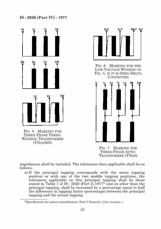
2.2.5 Marking for three-phase three-winding transformer havingconnection symbol ‘YNyn0d5’ is shown in Fig. 5.
2.2.6 Marking for the low-voltage winding in Fig. 5, if it is open-deltaconnection, is shown in Fig. 6.
2.2.7 Marking for three-phase auto-transformer is shown in Fig. 7.
2.2.8 Marking for booster transformer with energizing windingconnected in delta is shown in Fig. 8.
NOTE — Figures 4 to 8 illustrate the marking as defined in 2.1.2, 2.1.3 and 2.1.4 andshow where the numeral characters denoting the end points of a phase-winding maybe omitted as given in 2.1.1.

IS : 2026 (Part IV) - 1977
6
3. TAPPINGSNOTE 1 — Clauses 3.1 to 3.4.2 are restricted to transformers having only one tappedwinding. For auto-transformers this means that the number of turns per phase ineither the HV or LV circuit is constant. Auto-transformers with tapped neutral aresubject to agreement between the manufacturer and the purchaser. However, somedefinitions have a wider field of application [see 2.5 of IS : 1885 (Part XXXVIII)-1977*].NOTE 2 — Tap-changing involving a phase displacement in the voltage is not takeninto account.
3.1 Requirements Valid for All Categories of Voltage Variation3.1.1 General — Transformers are not provided with tappings unlessspecifically required. When tappings are required, it shall be stated ifthey are intended for off-circuit or for on-load tap-changing.3.1.2 Principal Tapping — Unless otherwise specified, the principaltapping is the mean tapping position if the number of tapping positionsis odd, or, if this number is even, that one of the two middle tapping
FIG. 1 TYPICAL MARKINGS FOR PHASE-WINDINGS
*Electrotechnical vocabulary: Part XXXVIII Transformers ( first revision ).

IS : 2026 (Part IV) - 1977
7
positions which is associated with the higher effective number of turns ofthe tapped winding; if the tapping thus defined is not a full-power tapping,the nearest full-power tapping shall be chosen [the principal tapping is afull-power tapping in accordance with 2.5.9 of IS : 1885(Part XXXVIII)-1977*].3.1.3 Tapping Range — The tapping range of the tapped winding shallbe expressed as follows:
a) If there are plus tappings and minus tappings : ±a percent or +apercent, –b percent, and
b) If there are only plus tappings or minus tappings : +a percent or –bpercent.
3.1.4 Short-Circuit Impedance — The winding(s) to which theimpedance is related shall be indicated as follows:
a) For a two-winding transformer, indication of the winding to which
FIG. 2 MARKINGS FOR SINGLE-PHASE TRANSFORMERS
*Electrotechnical vocabulary: Part XXXVIII Transformers ( first revision ).

IS : 2026 (Part IV) - 1977
8
the impedance is related shall suffice (HV impedance, LVimpedance), and
b) For a multi-winding transformer the impedance of the HV/LVwindings pair, related to the HV winding for instance, shall bereferred to as the HV/LV impedance (HV being underlined) or asthe HV impedance of the HV/LV pair.
Depending on system conditions, the impedance may usually be relatedto either one of the windings. If the power flow is only from the HVwinding to the LV winding, it is advisable to relate the impedance to theHV winding.
NOTE — Three-winding transformers and auto-transformers with low-voltage ratio(such as below 2 : 1) need special consideration and in such cases 3.1.4.1 and 3.1.4.2may not apply.
3.1.4.1 Principal tapping — The short-circuit impedance shall bespecified in ohms per phase related to one winding in addition to the‘impedance voltage at rated current’ expressed as a percentage.3.1.4.2 Other tappings — If necessary, the short-circuit impedances onother tappings may be specified. If this is done, the extreme tapping
FIG. 3 TYPICAL MARKINGS FOR SINGLE-PHASE AUTO-TRANSFORMER

IS : 2026 (Part IV) - 1977
9
FIG. 4 MARKINGS FOR THREE-PHASE TWO-WINDING TRANSFORMERS
IS : 2026 (Part IV) - 1977
10
impedances shall be included. The tolerances then applicable shall be asfollows:
a) If the principal tapping corresponds with the mean tappingposition or with one of the two middle tapping positions, thetolerances applicable on this principal tapping shall be thosestated in Table 7 of IS : 2026 (Part I)-1977* and on other than theprincipal tapping, shall be increased by a percentage equal to halfthe difference in tapping factor (percentage) between the principaltapping and the actual tapping.
FIG. 6 MARKING FOR THE LOW-VOLTAGE WINDING IN FIG. 5, IF IT IS OPEN-DELTA
CONNECTED
FIG. 5 MARKING FOR THREE-PHASE THREE-
WINDING TRANSFORMER (YNyn0d5)
FIG. 7 MARKING FOR THREE-PHASE AUTO-
TRANSFORMER (YNa0)
*Specification for power transformers: Part I General ( first revision ).

IS : 2026 (Part IV) - 1977
11
b) In the other cases the tapping range shall be considered asbalanced about the mid-tapping position and the tolerances shallbe calculated as before but assuming tolerances according to Table7 of IS : 2026 (Part I)-1977* applying to the mid-tapping position.This may mean a true tolerance on principal tapping in excess ofthat in Table 7 of IS : 2026 (Part I)-1977*.
For a specified tapping range, the simplest method is to fix,according to the above calculation, only the minimum andmaximum values of impedance including the tolerances.
NOTE — For tapping ranges in excess of an overall 25 percent of where the tolerancesderived may result in unacceptable levels of impedance, tolerances shall be subject toagreement between the manufacturer and the purchaser.
3.1.5 Load Loss Requirements — The purchaser shall state for whichtapping connections, in addition to that on the principal tapping, valuesfor load loss shall be declared by the manufacturer. They usuallyinclude the extreme tappings.
The reference current of two-winding transformer is, for any tapping,equal to the tapping current.
FIG. 8 MARKING FOR BOOSTER TRANSFORMER WITHENERGIZING WINDING CONNECTED IN DELTA
*Specification for power transformers: Part I General ( first revision ).

IS : 2026 (Part IV) - 1977
12
For multi-winding transformers the reference current or the referencepower shall be stated.3.1.6 Requirements Related to Temperature-Rise ( Guarantees andTests ) — Temperature-rise limit values are applicable to the tappingposition as specified in 3.4 of IS : 2026 (Part 2)-1977 ‘Specification forpower transformers, Part 2 Temperature-rise’. Except in such caseswhere agreed to between the purchaser and the supplier, thetemperature-rise test need be carried out on one tapping only, chosen inaccordance with 3.4 of IS : 2026 (Part 2)-1977.3.1.7 Requirements Related to Operation at a Voltage Higher than theTapping Voltage — For all tappings, requirements shall be the same asfor the principal tapping the words ‘rated voltage’ and ‘rated current’being changed into ‘tapping voltage’ and ‘tapping current’.3.2 Requirements for Constant Flux Voltage Variation (CFVV)3.2.1 The constant flux voltage variation shall be the voltage variationwhen the tapping voltage is:
a) rated voltage for any untapped winding, orb) rated voltage multiplied by the tapping factor for the tapped winding.NOTE 1 — The magnetic-flux (at no-load) is the same for all tapping positions, thusthe name constant flux variation.NOTE 2 — Figure 9a shows the variation of the tapping voltage as a function of thetapping factor.
3.2.2 Additional Requirements for CFVV3.2.2.1 Specifications shall indicate ( see A-1 ):
a) the category of voltage variation CFVV,b) the rated power of the transformer or the rated power of each
winding in the case of a multi-winding transformer,c) the rated voltages,d) which winding is the tapped winding, and its tapping range,e) the number of tapping positions, or the tapping step. In the first
case, the tapping steps shall be supposed to be approximatelyequal.
NOTE — Whenever nothing is indicated on the category of voltage variation, categoryCFVV is assumed to be applied.
3.2.2.2 Tapping currents and tapping power ( see Fig. 9b and 9c ) — Ifnothing is specified, it is implied that all tappings are full-powertappings.If a ‘maximum current tapping’ is specified, it is implied that above thistapping (higher tapping factors) the tappings are full-power tappingsand that below this tapping the tapping current is constant for thetapped winding whence a reduced tapping power.
NOTE 1 — In the first case (only full-power tappings) the extreme minus tapping maybe called ‘maximum current tapping’.

IS : 2026 (Part IV) - 1977
13
FIG. 9 CONSTANT FLUX VOLTAGE VARIATION(With constant power l1 in Fig. 9b and 9c, and
with limited current l2 in Fig. 9b and 9c)

IS : 2026 (Part IV) - 1977
14
3.2.3 Separate Winding Transformers of Rated Power up to 3 150 kVAand a Tapping Range up to ± 5 Percent — Unless otherwise specified:
a) the principal tapping shall be the maximum current tapping(tapping current of the tapped winding equal to rated current forall the minus tappings), and
b) the short-circuit impedance and load loss guarantees shall relate,only to the principal tapping.
3.3 Requirements for Variable Flux Voltage Variation (VFVV)3.3.1 Variable flux voltage variation shall be the voltage variation whenthe tapping voltage is constant for the tapped winding (and equal to itsrated voltage) ( see Fig. 10a ).3.3.2 Additional Requirement for VFVV3.3.2.1 Specifications shall indicate ( see A-2 ):
a) category of voltage variation: variable flux voltage variation(VFVV);
b) the rated power of the transformer or the rated power of eachwinding in the case of a multi-winding transformer;
c) the rated voltages; for each untapped winding the extreme tappingvoltages shall be specified and the rated voltage underlined;
d) which winding is the tapped winding and what is its tappingrange; and
e) the number of tapping positions or the tapping step.3.3.2.2 Tapping currents and tapping power ( see Fig. 10b and 10c ) — Ifnothing is specified, it shall be implied that all tappings are full-powertappings. If a ‘maximum current tapping’ is specified, it shall be impliedthat below this tapping (lower tapping factors) the tappings arefull-power tappings and that above this tapping, the tapping current isconstant for the untapped winding.3.3.2.3 Requirements related to no-load loss and no-load current — Thefollowing shall be agreed between the manufacturer and the purchaser:
a) For which tappings (other than the principal tapping) values ofno-load losses shall be stated by the manufacturer and for whichtappings value of no-load current shall be stated, and
b) The voltages to be considered for those tappings.
3.4 Requirements for Combined Voltage Variation (Cb.VV)3.4.1 Combined voltage variation shall be the voltage variation whichcombines as follows CFVV and VFVV ( see Fig. 11a ):
a) Below a certain value of the tapping factor, the tapping voltagesvary (as in CFVV); and
b) Above this value the tapping voltage of the tapped winding isconstant (as in VFVV).

IS : 2026 (Part IV) - 1977
15
FIG. 10 VARIABLE FLUX VOLTAGE VARIATION(With constant power l1 in Fig. 10b and 10c, and
with limited current l2 in Fig. 10b and 10c)

IS : 2026 (Part IV) - 1977
16
The tapping corresponding to this value of the tapping factor is called‘maximum voltage tapping’.3.4.2 Additional Requirements for Cb.VV3.4.2.1 Specifications shall indicate:
a) the category of voltage variation : Cb.VV;b) the rated power of the transformer or the rated power of each
winding in the case of a multi-winding transformer;c) the rated voltages;d) which winding is the tapped winding, and its tapping range;e) the number of tapping positions or the tapping step; andf) which tapping is the ‘maximum voltage tapping’ with the
corresponding tapping voltages ( see Fig. 11a).3.4.2.2 Tapping currents and power — If a ‘maximum current tapping’is specified, with the corresponding tapping currents, it shall be impliedthat below this tapping (lower tapping factors) the tapping current isconstant for the untapped winding ( see Fig. 11b ). This tapping, themaximum voltage tapping and the intermediate tappings shall be thefull-power tappings. The other tappings shall be reduced-powertappings ( see Fig. 11c ).
NOTE — The information considered in 3.4.2.1(a) and 3.4.2.1(b) may be given in atable as in A-3.
3.4.2.3 Requirements related to no-load loss — These shall be the sameas in 3.3.2.3.
4. CONNECTIONS4.1 Connections of Phase-Windings — The star, delta, or zigzagconnection of a set of phase-windings of a three-phase transformer or ofwindings of the same voltage of single-phase transformers associated ina three-phase bank shall be indicated by the letters , D or Z for thehigh-voltage winding and y, d or z for the intermediate and low-voltagewindings. If the neutral point of a star or a zigzag connected winding isbrought out, the indication shall be N or ZN and yn or zn respectively.For the auto-transformer in which the two windings have a commonpart, the winding of the pair which has the lower rated voltage isindicated by the letter a.4.2 Phase Displacement Between Windings — The vector relatingto the high-voltage winding shall be taken as the vector of origin.Examples of vector diagrams showing the use of the clock-hour figure[see 2.10.8 of IS : 1885 (Part XXXVIII)-1977*] are given in Fig. 12.For multi-winding transformers, the vector for the high voltage windingremains the reference vector and the symbol for this winding shall begiven first. Other symbols shall follow in diminishing sequence of ratedvoltages of the other windings.
*Electrotechnical vocabulary : Part XXXVIII Transformers ( first revision ).

IS : 2026 (Part IV) - 1977
17
FIG. 11 COMBINED VOLTAGE VARIATION

IS : 2026 (Part IV) - 1977
18
FIG. 12 ILLUSTRATIONS OF THE USE OF CONNECTION SYMBOLS

IS : 2026 (Part IV) - 1977
19
In the case of auto-transformers in which two windings have a commonpart, the letter a, which corresponds to the winding with the lower ratedvoltage of the pair, shall be written after the letter corresponding to thewinding with the higher rated voltage of the pair, for instance Naod11(the pair of auto-connected windings includes the winding with thehigher rated voltage or Dyni1) (the pair of auto-connected windings doesnot include the high-voltage winding).
NOTE — Appendix B gives details of a number of connections that are in general use,but it does not purport to be complete.
Examples:
1) In the case of a transformer with three windings respectively for150 000 V (delta), 60 000 V (star with neutral point not broughtout) and 10 000 V (star with neutral point not brought out), thedesignation (for the case where the two-star voltages are in phasewith one another and lag by 30° on the delta voltage) would be:
Dy1y1
2) In the case of another transformer with three windingsrespectively for 6 000 V (star with neutral point brought out),380 V (star with neutral point not brought out) and 220 V (zigzagwith neutral point not brought out), the designation (for the casewhere the two-star voltages are in phase with one another and thezigzag voltage lags by 30°) would be:
NyoziNOTE — In practice, due in particular to the rules laid down in 4.2, no confusion shallarise if, in data transmission, only capital or small letters are used.
A P P E N D I X A( Clauses 3.2.2, 3.3.2 and 3.4.2 )
EXAMPLES OF SPECIFICATIONS FOR TRANSFORMERS FITTED WITH TAPPINGS
A-1. CONSTANT FLUX VOLTAGE VARIATION
A-1.1 Example with Two Variants:
Transformer having a 66/20 kV, 3 phase, 40 MVA rating and a ±10percent tapping range on the 66 kV winding, with 11 tapping positions.

IS : 2026 (Part IV) - 1977
20
a) First variant : All tappings are full power tappingsCategory of voltage variation : CFVVRated power : 40 MVARated voltages : 66/20 kVTapped winding : 66 kV—tapping range ±10 percentNumber of tapping positions : 11
b) Second variant : With reduced power tappings : addMaximum current tapping : tapping –5 percent
NOTE — Unless additional specifications are given, the tapping current of the HVwinding is then limited to 368 amperes from the tapping –5 percent to the extremetapping –10 percent where the tapping power is reduced to 38 MVA.
A-2. VARIABLE FLUX VOLTAGE VARIATIONA-2.1 Transformer having a 66/6 kV, 3 phase, 20 MVA rating and a +15percent –5 percent tapping range on the HV winding, but having aconstant tapping voltage for the HV winding and a variable tappingvoltage for the LV winding, between
NOTE — The ‘tapping current’ of the untapped winding (LV) is then limited to 2 020amperes from the tapping +5 percent to the extreme tapping +15 percent where thetapping power is reduced to 18.2 MVA.
A-3. COMBINED VOLTAGE VARIATIONA-3.1 The specifications may be stated in a tabular form as given inTable 1.A-3.1.1 The ‘maximum voltage tapping’ is the tapping +6 percent.A-3.1.2 The ‘maximum current tapping’ is the tapping –9 percent.
= 6.32 and = 5.22 kV
Variant 1 : There are only ‘full power tappings’ :Category of voltage variation : VFVVRated power : 20 MVARated voltages : 66/6 kVTappings on winding : 66 kV (tapping range +15 percent–5 percent)Tapping voltages of 6 kV winding : 6.32, 6 and 5.22 kVNumber of tapping positions : 11
Variant 2 : With reduced power tappings shall be added :Maximum current tapping : tapping +5 percent
60.95----------- 6
1.15-----------

IS : 2026 (Part IV) - 1977
21
A P P E N D I X B( Clause 4.2 )
TRANSFORMER CONNECTIONS IN GENERAL USE
B-1. THREE-PHASE TRANSFORMERS
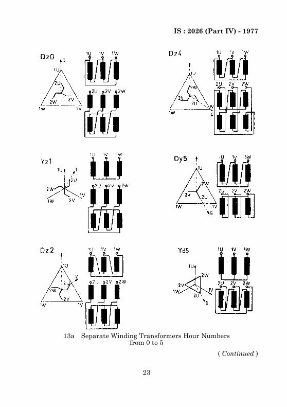
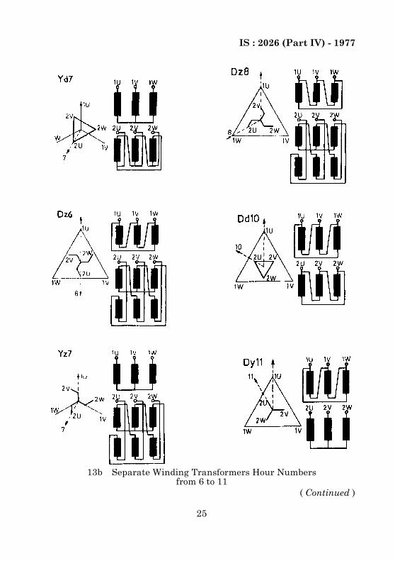
B-1.1 Separate Winding Transformers — Figures 13a and 13b givedetails of three-phase transformer connections that are in general useand the angle of phase shift associated with them. The connectiondiagram assumes the same winding direction for all windings.
TABLE 1 COMBINED VOLTAGE VARIATION RATING 160/20 kV, 40 MVA, 3-PHASE, TAPPED WINDING: XV — TAPPING RANGE ±15 PERCENT
NUMBER OF TAPPING POSITIONS : 21
( Clause A-3.1 )
TAPPINGS VOLTAGE RATIO
TAPPING VOLTAGES TAPPING CURRENT TAPPING POWER
UHV ULV IHV ILV
(1) (2) (3) (4) (5) (6) (7)kV kV A A MVA
1(+15%) 9.20 169.6 18.43 125.6 1 155 36.86
Intermediary Decreasing 169.6 Increasing Increasing 1 155 Increasing
7 (+6%) 8.48 169.6 20 136.2 1 155 40
Intermediary Decreasing Decreasing 20 Increasing 1 155 40
15 (–9%) 7.28 145.6 20 158.7 1 155 40
Intermediary Decreasing Decreasing 20 158.7 Decreasing Decreasing
21 (–15%) 6.80 136 20 158.7 1 080 37.4
NOTE 1 — In completing the intermediate lines the preceding table may be used on arating plate.NOTE 2 — Compare these specifications and ‘CFVV’ specifications which would be:
160±15 percent/20 kV, 40 MVAThe only difference is that the HV tapping voltage does not exceed the ‘systemhighest voltage’ of the HV system, which is 170 kV.There is no difference in the currents.

IS : 2026 (Part IV) - 1977
22
B-1.2 Auto-transformers — It should be remembered that phasedisplacements different from clock-hours 0, 4 and 8 are not suitable foruse with star-connected auto-transformers.
Figure 13c is limited to the connection symbol ao.
13a Separate Winding Transformers Hour Numbersfrom 0 to 5
( Continued )
IS : 2026 (Part IV) - 1977
23
13a Separate Winding Transformers Hour Numbersfrom 0 to 5
( Continued )

IS : 2026 (Part IV) - 1977
24
13a Separate Winding Transformers Hour Numbersfrom 0 to 5
13b Separate Winding Transformers Hour Numbersfrom 6 to 11
( Continued )
IS : 2026 (Part IV) - 1977
25
13b Separate Winding Transformers Hour Numbersfrom 6 to 11
( Continued )

IS : 2026 (Part IV) - 1977
26
13b Separate Winding Transformers Hour Numbersfrom 6 to 11

IS : 2026 (Part IV) - 1977
27
B-2. EXAMPLE OF THREE SINGLE-PHASE TRANSFORMERS CONNECTED TO FORM A THREE-PHASE BANK
B-2.1 In this case, both ends of each winding of each single-phasetransformer are brought out to terminals and given markings. Adiagram of such a three-phase bank is given in Fig. 14, by way ofexample; in which the corresponding terminals are called 1 U and 2 Ufor the first single-phase transformers, 1 V and 2 V for the second one, 1W and 2 W for the third one.
13c Auto-transformers Yao
FIG. 13 DESIGNATION OF CONNECTIONS OF THREE-PHASE TRANSFORMERS BY CONNECTION SYMBOLS

IS : 2026 (Part IV) - 1977
28
FIG. 14 EXAMPLE OF THREE SINGLE-PHASE TRANSFORMERS CONNECTED TO FORM A THREE-PHASE
BANK (CONNECTION SYMBOL Yd5)

Bureau of Indian StandardsBIS is a statutory institution established under the Bureau of Indian Standards Act, 1986 to promoteharmonious development of the activities of standardization, marking and quality certification ofgoods and attending to connected matters in the country.CopyrightBIS has the copyright of all its publications. No part of these publications may be reproduced in anyform without the prior permission in writing of BIS. This does not preclude the free use, in the courseof implementing the standard, of necessary details, such as symbols and sizes, type or gradedesignations. Enquiries relating to copyright be addressed to the Director (Publications), BIS.Review of Indian StandardsAmendments are issued to standards as the need arises on the basis of comments. Standards are alsoreviewed periodically; a standard along with amendments is reaffirmed when such review indicatesthat no changes are needed; if the review indicates that changes are needed, it is taken up forrevision. Users of Indian Standards should ascertain that they are in possession of the latestamendments or edition by referring to the latest issue of ‘BIS Catalogue’ and ‘Standards : MonthlyAdditions’.This Indian Standard has been developed by Technical Committee : ETDC 16
Amendments Issued Since Publication
Amend No. Date of IssueAmd. No. 1 December 1984Amd. No. 2 September 1993
BUREAU OF INDIAN STANDARDSHeadquarters:
Manak Bhavan, 9 Bahadur Shah Zafar Marg, New Delhi 110002.Telephones: 323 01 31, 323 33 75, 323 94 02
Telegrams: Manaksanstha(Common to all offices)
Regional Offices: Telephone
Central : Manak Bhavan, 9 Bahadur Shah Zafar MargNEW DELHI 110002
323 76 17323 38 41
Eastern : 1/14 C. I. T. Scheme VII M, V. I. P. Road, KankurgachiKOLKATA 700054
337 84 99, 337 85 61337 86 26, 337 91 20
Northern : SCO 335-336, Sector 34-A, CHANDIGARH 160022 60 38 4360 20 25
Southern : C. I. T. Campus, IV Cross Road, CHENNAI 600113 235 02 16, 235 04 42235 15 19, 235 23 15
Western : Manakalaya, E9 MIDC, Marol, Andheri (East)MUMBAI 400093
832 92 95, 832 78 58832 78 91, 832 78 92
Branches : AHMEDABAD. BANGALORE. BHOPAL. BHUBANESHWAR. COIMBATORE.FARIDABAD. GHAZIABAD. GUWAHATI. HYDERABAD. JAIPUR. KANPUR. LUCKNOW.NAGPUR. NALAGARH. PATNA. PUNE. RAJKOT. THIRUVANANTHAPURAM.VISHAKHAPATNAM