Embed Size (px)
Citation preview

������������������������������������������������ ���� ���� ���� ������������
��������� ����� ����� ����� ������ ������� ������� ������� ������������
������ �� ��������� �� ��������� �� ��������� �� ��� ����
Handbook Ref No. MH067/Issue L File Ref: R203-v5l.doc


������������������������������������������������ ���� ���� ���� ��������
����
��������������� ��� ��� ��� ������ ����� ����� ����� ��������������
����
������ �� ��������� �� ��������� �� ��������� �� ��� ����
�� ��� ����� ��� ����� ��� ����� ��� ��� 1. Introduction 2. Specification 3. Operation 4. Irradiance Measurements 5. Illuminance Measurements 6. UVA Irradiance Measurements 7. Battery Replacement 8. Photopic Response 9. Cosine Angular Response 10. Calibration Description 11. Block Diagram 12. Programming via the RS232 Interface 13. Environmental Care, Recycling and Disposal


R203 Radiometer Irradian Limited
1 �
������� ����������� ����������� ����������� �������� ���� The Irradian R203 Radiometer is a portable instrument designed for accurate measurement of irradiance (mW.m
-2) in the spectral region 400
to 1060nm and illuminance (lux). The model R203UV measures Illuminance and ultra-violet irradiance in the UVA region. The radiometer comprises of a hand held display unit with micro processor control, a detector / amplifier assembly with connecting cable and associated filter rings. (An illuminance filter ring, an irradiance filter ring or a UVA irradiance filter ring.) The sensor in the detector assembly is a large area silicon photodiode with excellent linearity and long term stability. The photopic filter ring model CIE-Cos, (illuminance measurements), fitted to the front of the silicon detector gives a response which closely matches the human eye response outlined by the CIE Vλ curve. This precise spectral correction gives high accuracy photometric measurements from light sources with different spectral distributions (see Section 10). The radiometric flat filter ring model RFF-Cos for visible and near infra-red irradiance measurements has specially selected filter glasses to flatten the response of the photodiode detector over the spectral region 400 to 1060nm. For ultra violet irradiance measurements the UVA-Cos filter ring is designed to respond to typical UV sources and has excellent blocking in the visible and infra red part of the spectrum. Each of the three filter rings screws directly into the detector body. A profiled diffuser fitted to the top of the filter rings gives the detector an accurate cosine corrected angular response. Model R203 is supplied with lux and RFF filter rings. Model R203UV is supplied with lux and UVA filter rings

Irradian Limited R203 Radiometer
� 2
������ �������������� �������������� �������������� �������� ���� DISPLAY UNIT Controller: 80C51 8bit micro-processor with a 3.1684MHz clock. Memory On board non volatile RAM for calibration factors and set-up parameters. Key Operation 8 switch key board with 11 LED indicators. Power Switch Microprocessor reset at switch on. Unit settings stored prior to shut down. Serial Interface Three wire RS232 serial interface. 4800 baud, no parity, 1 stop bit. Integration Time 0.33s Conversion Scale 17 bit Accuracy: Measurement accuracy ±1digit with a linearity error of <1%. Display: 4½ digit LCD display. Character height 10mm. Display illumination: A LED back light can be switched on to illuminate the display for readings in low ambient light situations. Power Supply: 9 volt PP3 battery. Power Consumption: Shut down mode <5µA Operating 10 - 20mA LED back light ~20mA Battery Life ~ 50 hours without backlight use

R203 Radiometer Irradian Limited
3 �
������ �������������� �������������� �������������� �������� (continued): Ranges: i) Irradiance (model R203 only) Up to 6 full scale decades measuring from*: 0 to 19.999 mW.m-2 0 to 199.99 mW.m-2 0 to 1.9999 W.m-2 0 to 19.999 W.m-2 0 to 199.99 W.m-2 0 to 1999.9 W.m-2 Resolution 0,001 mW.m-2 on range 1.
ii) Illuminance (both models) Up to 6 full scale decades measuring from*: 0 to 1.9999 lux 0 to 19.999 lux 0 to 199.99 lux 0 to 1999.9 lux 0 to 19999 lux 0 to 19999 x 10 lux Resolution 0,0001 lux on range 1.
iii) UVA Irradiance (model R203 UV only) Up to 6 full scale decades measuring from*: 0 to 199.99 mW.m-2 0 to 1999.9 mW.m-2 0 to 19.999 W.m-2 0 to 199.99 W.m-2 0 to 1999.9 W.m-2 0 to 19999 W.m-2 Resolution 000,01 mW.m-2 on range 1. * Other ranges available on request.
Calibration Absolute calibration accuracy ±3% illuminance, ±7.5% ultraviolet to national standards. Photopic colour correction integrated error of ±1% over visible spectrum.

Irradian Limited R203 Radiometer
� 4
������ �������������� �������������� �������������� �������� (continued): Front Panel Controls: RANGE Select auto ranging or manual range control. UNITS Select between each of the three filter rings for measurements of irradiance in (m)W.m
-2
or illuminance in lux or UVA irradiance in (m)W.m
-2.
Select AUX for additional accessory (if supplied). ZERO Initiates a zero or background measurement routine on all five ranges. HOLD/RUN Display is held at present reading until HOLD button is pressed again. Select to run or hold a special mode. MODE Select between AVERAGE, MIN, MAX and INTEGRATE modes. FUNCTION/RESET Press to reset function values to zero. RESET Press to return to normal measurement mode from Manual range mode or special modes. Note the display hold is not reset. � Power on / off button. � Display backlight on off button. Display backlight will switch off after a programmable delay, factory setting 60 secs. Connectors: 8 pin DIN type detector connector. 5 pin DIN type RS232 connector. Temperature Range: 0 to 40°C. 80% RH. Dimensions: 150 x 80 x 45mm. High impact polystyrene. Weight: 350g

R203 Radiometer Irradian Limited
5 �
������ �������������� �������������� �������������� �������� (continued): LABORATORY DETECTOR, Model DET203QR
Amplifier PCBPhotodiode
Cable
Accessory Mounting Thread
The DET203QR laboratory detector comprises of an aluminium housing, photodiode and PCB assembly. Detector: 33mm² silicon photodiode Temperature Coefficient: -0.10 %/°C Amplifier Gain 10
9 V/A to 10
3 V/A
Current to Frequency 0 - 0.5Mhz Linearity Error: <1% from 1 to 100 000 lux Temperature Range: Operation: -20 to +60°C Storage: -20 to +70°C Detector Housing: Black anodised aluminium alloy housing.
Each optical accessories screws into the detector housing on a 1.125" x 20 T.P.I. The detector amplifier is connected to the display unit via a multicore cable to a eight pin DIN type connector.

Irradian Limited R203 Radiometer
� 6
������ �������������� �������������� �������������� �������� (continued): RADIOMETRIC FLAT FILTER RING, Model RFF-Cos
Spectral Response: Refer Figure 1.
Angular Response: Accurately cosine corrected to Lambert's Cosine Law. Maximum error is less than ±3.5% from true response to 70° from normal incidence, reference Figure 6.
Filter ring assembly: Black anodised aluminium alloy ring with screw thread 1.125" x 20 T.P.I. Multiple coloured filter glasses individually selected to flatten the silicon photodiode response across the visible and near infra-red spectrum.
Specially profiled acrylic diffuser for high accuracy cosine angular response.
RFF-Cos Filter Ring with DET203QR Detector Typical Spectral response
0
20
40
60
80
100
360 440 520 600 680 760 840 920 1000 1080
Response
Wavelength (nm)
Figure 1

R203 Radiometer Irradian Limited
7 �
������ �������������� �������������� �������������� �������� (continued): PHOTOPIC FILTER RING, Model CIE-Cos
Spectral Response: Refer Figures 2, 5 and Section 8.
Angular Response: Accurately cosine corrected to Lambert's Cosine Law. Maximum error is less than ±3.5% from true response to 70° from normal incidence, reference Figure 6.
Filter ring assembly: Black anodised aluminium alloy ring with screw thread 1.125" x 20 T.P.I. Multiple coloured filter glasses individually selected for close matching to Vλ. Specially profiled acrylic diffuser for high accuracy cosine angular response.
CIE-Cos Filter Ring with DET203QR Detector Typical Spectral Response
Figure 2

Irradian Limited R203 Radiometer
� 8
������ �������������� �������������� �������������� �������� (continued): UVA FILTER RING, Model UVA-Cos
Spectral Response: Refer Figure 3. λ
peak @ 365 ±2nm, FWHM 35 ±2nm.
Visible & NIR Blocking: >105 from 420 to 1000nm
Angular Response: Accurately cosine corrected to Lambert's
Cosine Law. Maximum error is less than ±3.5% from true response to 70° from normal incidence, reference Section 9.
Filter ring assembly: Black anodised aluminium alloy ring with screw thread 1.125" x 20 T.P.I. Multiple coloured filter glasses individually selected . Specially profiled diffuser for high accuracy cosine angular response.
UVA-Cos Filter Ring with DET203QR Detector
Typical Spectral Response
0
20
40
60
80
100
320 330 340 350 360 370 380 390 400 410
Response
Wavelength (nm)
Figure 3
R203 Radiometer Irradian Limited
9 �
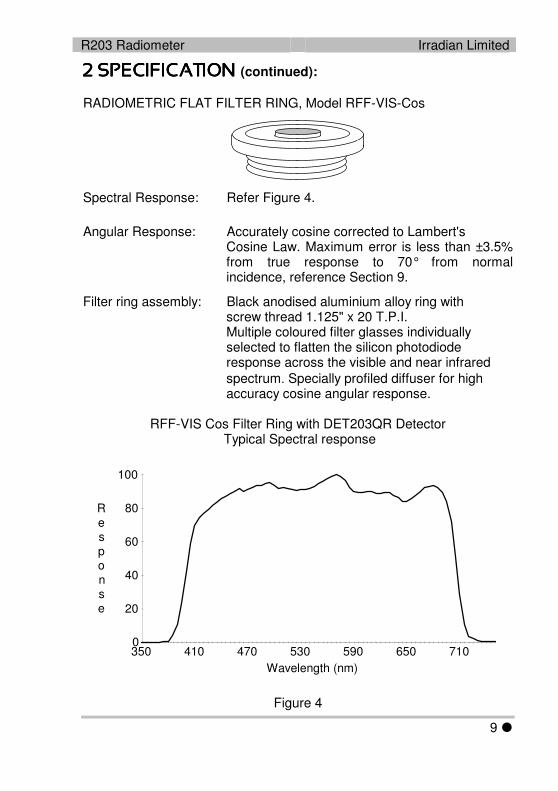
������ �������������� �������������� �������������� �������� (continued): RADIOMETRIC FLAT FILTER RING, Model RFF-VIS-Cos
Spectral Response: Refer Figure 4.
Angular Response: Accurately cosine corrected to Lambert's Cosine Law. Maximum error is less than ±3.5% from true response to 70° from normal incidence, reference Section 9.
Filter ring assembly: Black anodised aluminium alloy ring with screw thread 1.125" x 20 T.P.I. Multiple coloured filter glasses individually selected to flatten the silicon photodiode response across the visible and near infrared spectrum. Specially profiled diffuser for high accuracy cosine angular response.
RFF-VIS Cos Filter Ring with DET203QR Detector
Typical Spectral response
0
20
40
60
80
100
350 410 470 530 590 650 710
Response
Wavelength (nm)
Figure 4

Irradian Limited R203 Radiometer
� 10
������������������������������������ ���� SETTING UP 1) With the unit OFF, plug the detector 8 way connector into the socket
on the top of the display unit. 2) Carefully screw the required filter ring to the detector housing.
Note: Clean the white diffuser on the filter rings if they are marked or dirty.
3) Press and release the power switch on the R203 display key pad. The
micro controller will initiate with the display momentarily showing:-
The radiometer will now search for the optimum range on the detector amplifier. A typical display is shown below.
An LED will illuminate indicating the units. This will be the same units prior to the last power off.
4) Press and release the UNITS switch to select the correct units required. For illuminance measurements with the CIE-Cos photopic filter ring, the correct units are lux. For irradiance measurements with the (VIS-)RFF-Cos radiometric filter ring, the correct units are mW.m-2 or W.m-2 and with the UVA-Cos filter ring the UVA LED will light together with either the mW.m-2 or W.m-2 LED.
5) It is recommended that the radiometer amplifier is nulled periodically. Place the supplied blanking cover over the filter ring. Press and release the ZERO switch and the display will momentarily show:-

R203 Radiometer Irradian Limited
11 �
������������������������������������ (continued): 6) The micro controller will now measure the amplifier offset on each of
the gain ranges and store these values in the non volatile memory. All subsequent measurements will first have one of these offsets subtracted before displaying the measurement. At the end of the nulling sequence the display will show:-
7) Remove the light cover from the detector. The equipment is now ready
for use. AVERAGE When the light is unstable, press and release the MODE switch. The radiometer will now switch to manual ranging, Manual LED on, if not yet previously in manual ranging. The Average LED will now switch on, but the Units LED will remain unchanged. To start an average sequence press and release the HOLD/RUN switch. Immediately the display will show a fluctuating signal, reflecting the light source fluctuations. After a short time the amplitude of the fluctuations will decrease and the display will begin to show a reading which represents the average light level during the period of the measurement. At any time the averaging process can be halted by pressing the HOLD/RUN button. At any time the averaging sequence can be reset by pressing and releasing the FUNCTION RESET switch. If the light level fluctuations are large and any one reading causes the detector amplifier to overload at this range the averaging process will be terminated and the display will show:-
To avoid an overload conditions RESET the radiometer and Manually change the RANGE to a lower lever. e.g. from a 34.00 range to 34.0.

Irradian Limited R203 Radiometer
� 12
������������������������������������ (continued): MIN & MAX LEVELS During an average measurement sequence the maximum and minimum values attained in the period are recorded. Press HOLD to halt the averaging sequence. Press the MODE button to select between Average, Min and Max. Note the Integrate display may overload and show - 0 L -. It is also possible to view a MIN or MAX recording sequence by selecting MIN or MAX prior to selecting RUN. Press FUNCTION RESET to set the maximum and average values to zero and the minimum to - 0 L -. Note the FUNCTION RESET will operate during a measurement sequence or in the HOLD mode. INTEGRATE For measurements of the integrated dosage or exposure press the MODE switch to select Integrate. Press the RUN switch to start the measurement. The display will now autorange as the dosage increases. Note the detector amplifier will not autorange and as with Average measurements if the amplifier overloads the display will show - 0 L - and the measurement will halt. Units for integrated measurements of both irradiance and UVA irradiance are mJ.m
-2 or J.m
-2 and for illuminance, lux seconds (lux.s).
At the end of the integration period HOLD the display. Use the MODE switch to also display the Min, Max and Average values. Press FUNCTION RESET to set the integrate, maximum and average values to zero and the minimum to - 0 L -. Note the FUNCTION RESET will operate during a measurement sequence or in the HOLD mode.
R203 Radiometer Irradian Limited
13 �
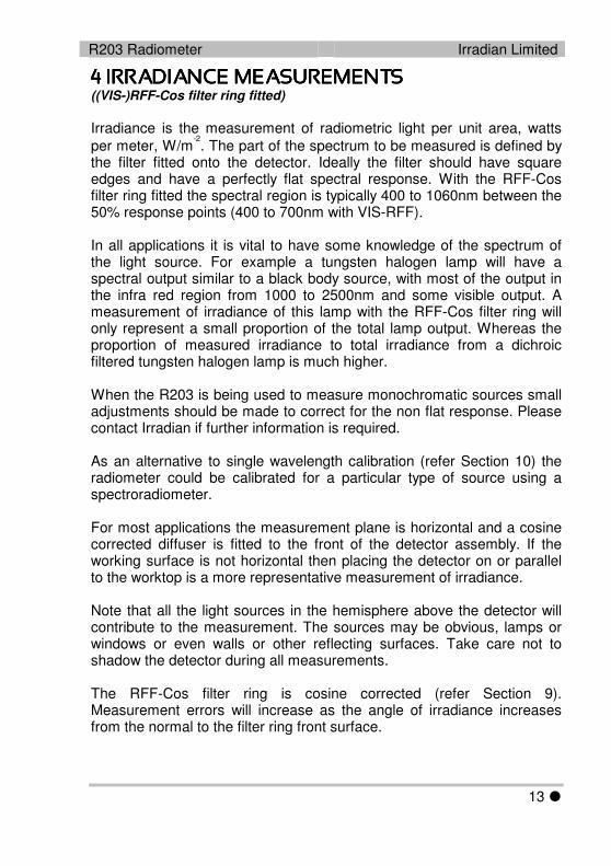
���������� ��� ������ �� ������������ ��� ������ �� ������������ ��� ������ �� ������������ ��� ������ �� �� ((VIS-)RFF-Cos filter ring fitted) Irradiance is the measurement of radiometric light per unit area, watts per meter, W/m
-2. The part of the spectrum to be measured is defined by
the filter fitted onto the detector. Ideally the filter should have square edges and have a perfectly flat spectral response. With the RFF-Cos filter ring fitted the spectral region is typically 400 to 1060nm between the 50% response points (400 to 700nm with VIS-RFF). In all applications it is vital to have some knowledge of the spectrum of the light source. For example a tungsten halogen lamp will have a spectral output similar to a black body source, with most of the output in the infra red region from 1000 to 2500nm and some visible output. A measurement of irradiance of this lamp with the RFF-Cos filter ring will only represent a small proportion of the total lamp output. Whereas the proportion of measured irradiance to total irradiance from a dichroic filtered tungsten halogen lamp is much higher. When the R203 is being used to measure monochromatic sources small adjustments should be made to correct for the non flat response. Please contact Irradian if further information is required. As an alternative to single wavelength calibration (refer Section 10) the radiometer could be calibrated for a particular type of source using a spectroradiometer. For most applications the measurement plane is horizontal and a cosine corrected diffuser is fitted to the front of the detector assembly. If the working surface is not horizontal then placing the detector on or parallel to the worktop is a more representative measurement of irradiance. Note that all the light sources in the hemisphere above the detector will contribute to the measurement. The sources may be obvious, lamps or windows or even walls or other reflecting surfaces. Take care not to shadow the detector during all measurements. The RFF-Cos filter ring is cosine corrected (refer Section 9). Measurement errors will increase as the angle of irradiance increases from the normal to the filter ring front surface.

Irradian Limited R203 Radiometer
� 14
������ �� �� ��� ������ �� �������� �� �� ��� ������ �� �������� �� �� ��� ������ �� �������� �� �� ��� ������ �� �� (CIE-Cos filter ring fitted) Illuminance is the measurement of photometric light per unit area, lumens per meter, lux, or lumens per square foot, footcandle. For most applications the measurement plane is horizontal and a cosine corrected diffuser is fitted to the front of the detector assembly. If the working surface is not horizontal then placing the detector on or parallel to the worktop is a more representative measurement of the illuminance. Note that all the light sources in the hemisphere above the detector will contribute to the illuminance measurement. The sources may be obvious, lamps or windows or even walls or other reflecting surfaces. Take care not to shadow the detector during all illuminance measurements. 1) Set up the radiometer as outlined in Section 3 with the illuminance
filter ring fitted and the units set to lux. 2) Place the detector at the measuring point and record the value on the
display. If the light levels are low it may be necessary to switch on the display back light.
3) The display can be read directly for all light levels from 0.0000 lux to
19 999 lux. Note however that for illuminance values of 20 000 to 199 990 lux, the x10 LED will illuminate and the displayed value must be multiplied by 10.
CONVERSION FACTORS 1 lux = 0.0929 footcandle 1 lux = 1 candela @ 1 meter 1 lux = d² candela @ d meters

R203 Radiometer Irradian Limited
15 �
�������������� ����������������� ����������������� ����������������� ��� ������ �� �������� �� �������� �� �������� �� �� (UVA-Cos filter ring fitted) CAUTION: ULTRA VIOLET RADIATION IS HAZARDOUS TO BOTH THE EYES AND SKIN. TAKE CARE TO AVOID PERSONAL EXPOSURE DURING MEASUREMENTS. Irradiance is the measurement of radiometric light per unit area, watts per meter, W/m
-2. The part of the spectrum to be measured is defined by
the filter fitted onto the detector. Ideally this should be a filter with a square spectral response. In practice it rarely is and the filter is defined with a peak response wavelength and a full width half maximum, FWHM bandwidth. In all applications it is vital to know the part of the spectrum being measured by the detector and filter, and if possible to know the spectrum of the light source. In addition the radiometer should be calibrated to best suit the measurement conditions. It may even be necessary to have more than one calibration factor for the same detector / filter combination. For most applications the measurement plane is horizontal and a cosine corrected diffuser is fitted to the front of the detector assembly. If the working surface is not horizontal then placing the detector on or parallel to the worktop is a more representative measurement of irradiance. Note that all the light sources in the hemisphere above the detector will contribute to the measurement. The sources may be obvious, lamps or windows or even walls or other reflecting surfaces. Take care not to shadow the detector during all measurements. The UVA-Cos filter ring is cosine corrected (refer Section 9). Measurement errors will increase as the angle of irradiance increases from the normal to the filter ring front surface. A useful technique for measuring the sensitivity of the detector filter to non ultra violet light is to place a high pass filter glass over the front of the filter ring and record the reading. If the high pass filter blocks all the light across the spectral response region of the UV filter then a zero reading would imply the detector/filter is only sensitive to the UV light. Readings other than zero would imply there is some sensitivity to visible or near infra-red light.

Irradian Limited R203 Radiometer
� 16
����������������� �� ������������������ �� ������������������ �� ������������������ �� ����� 1) Switch off the radiometer before changing the battery. 2) Slide open the battery compartment on the back of the radiometer and
pull out the battery. Disconnect from the battery clip 3) Replace with a size PP3 9 volt battery. 4) Place battery inside compartment and slide cover closed. 5) Note it will be necessary to switch on and off the radiometer before
normal operation will commence.

R203 Radiometer Irradian Limited
17 �
��� ���� ��� ���� ��� ���� ��� ���� ������ �������� �������� �������� ������ Photometry is the measurement of visible light. Irradian's photopic filter and photodiode closely matches the response of the standard human eye as published by the CIE (CIE Vλ). The spectral response of the photodiode detector with the photopic filter ring is plotted beside the ideal CIE response.
DET203QR + CIE-Cos Relative Response
Figure 5
Radiometers and photometers which do not closely match the response are often supplied with correction factors for different types of lamps and light sources. This means that the user has to identify the type of source being measured and correct the meter reading. This procedure becomes more unreliable when sources are mixed, for example office lighting in combination with daylight through a window. The response of the Irradian radiometer is such that the error for a wide variety of sources is typically < 2%.

Irradian Limited R203 Radiometer
� 18
!����� ���� ����������� ��!����� ���� ����������� ��!����� ���� ����������� ��!����� ���� ����������� ������ Irradiance and illuminance are both a measurement of light incident on a unit area, Watts/m² and Lumens/m² respectively. A detector will measure this reliably when the light beam is perpendicular to the detector's surface. Accurate measurements of irradiance and illuminance require that the detector should respond to light over a 180° field of view. More importantly, this response should be proportional to the cosine of the angle of light incident on the detector. To ensure that the integration of light from all angles is correct, the cosine diffuser fitted to the front of the filter ring is profiled such that the angular response of the detector decreases with Cos(i) as the angle between the source and detector increases from 0 to 90°.
True Cosine Response
Figure 6
Irradian's cosine diffusers are corrected to match the cosine response to within ±3.5% up to angles of 70°. This ensures that the meter correctly reads irradiance or illuminance whether it is measuring scattered light (from an overcast sky) or a point source (a single lamp in a dark room).
R203 Radiometer Irradian Limited
19 �
� ����������� ������������ ����������� ������������ ����������� ������������ ����������� ����������� ���� Irradian holds a number of quartz tungsten halogen and deuterium lamps, radiometers and a silicon photodiodes which are routinely calibrated by the National Physics Laboratory and other accredited laboratories in the UK. Photometric Calibration During manufacture each photopic filter is scanned for the best match to the CIE response. A graph of the final filter/detector response is provided. This data is available on request for importing into a spreadsheet. The radiometer is calibrated for illuminance using a lamp of colour temperature 2855K ±50K. Irradian estimates the absolute illuminance calibration error to be ±3% for a source of illuminant A at normal incidence. The errors mentioned in Sections 4 and 5, namely spectral response and cosine angular error, are small for most applications. Radiometric Calibration Both the visible / near infra red irradiance and the UVA irradiance filter rings are calibrated using monochromatic light. The wavelength is specified on the calibration certificate. However either or both the filter rings can be calibrated with the radiometer to measure a particular source and made to exactly match that of a spectroradiometer covering the required spectral region. Spectroradiometric calibrations can be carried out on site or at our laboratory. Contact Irradian for further details. As with all measuring equipment a routine calibration is recommended, typically annually, but with frequent use by a number of different users a shorter recalibration period may be necessary.

Irradian Limited R203 Radiometer
� 20
������� �������������� �������������� �������������� ������� ����
DiffuserFilterDetector
Amp
Gain Control
v to fCounter
µController
Keypad
Liquid CrystalDisplay
Display Driver
RS232 Driver
& LEDs
Detector Amplifier
Micro-Controlled Display Unit

R203 Radiometer Irradian Limited
21 �
�������� �� �������������� �� �������������� �� �������������� �� �������� ���������� ��������� ���������� ��������� ���������� ��������� ���������� ����������� Serial Port Settings: 4800 baud, no handshaking Single letter commands S Toggle through possible gain ranges (manual mode) Reset to autorange with R command. U Toggle through possible units, lux, UVA & Aux as applicable F Toggle through possible functions I Function reset H Toggles hold/go Z Zeros light meter R Resets light meter B Toggles backlight s Sends data continuously via the RS232 o Sends one set of data via the RS232

Irradian Limited R203 Radiometer
� 22
�������� �� �������� ���������� ��������������� �� �������� ���������� ��������������� �� �������� ���������� ��������������� �� �������� ���������� ����������� (continued):
12.1 Windows 3.1 & Windows 95 Setting up remote control via Microsoft TERMINAL.EXE
1) Connect the cable between the RS232 socket on the light meter and the COM port on the PC.
2) Switch on the light meter.
3) Run Terminal program.
4) Go to the Settings / Communications screen and set the baud to 4800 and the COM port to suit.
5) Go to the Settings / Text Transfers and select Line at a time with 1/10th second delay.
6) Check the RS232 link by a switch to the manual range, LED on using the command 'S', (capital S).
7) Reset to the auto range, LED off using the command 'R', (capital R).
8) Type 'o' for one packet of data and 's' for continuous data. Type 's' to stop the data flow.
9) To save the terminal setup go to File / Save As and save the settings. When restarting the program the settings can be reloaded with File / Load filename. Now actions 4 and 5 can be omitted.
Logging data continuously to a file using Microsoft TERMINAL.EXE
1) Run the Terminal program with the correct settings.
2) Set up the radiometer and send the command 's' via Terminal to transmit data continuously from the radiometer.
3) Go to Transfers / Receive Text File. Enter filename for the stored data (e.g. log1.txt).
4) On entering the file name, Terminal will now store all the readings transmitted from the radiometer in a file log1.txt. The file is saved to the computer by pressing STOP on the terminal screen.

R203 Radiometer Irradian Limited
23 �
�������������������������� �� �������� ���������� ��������� �� �������� ���������� ��������� �� �������� ���������� ��������� �� �������� ���������� ����������� (continued): 12.2 Windows 95, Windows 98 and later editions Setting up remote control via Microsoft HYPERTERMINAL.EXE
1) Connect the cable between the RS232 socket on the light meter and the COM port on the PC.
2) Switch on the light meter.
3) Run the HyperTerminal program.
4) Enter a name for the session (e.g. R203 etc.).
5) Select the type of connection required, either option 'direct to com 1' or 'direct to com 2' depending on which com port is to be used.
6) Enter the details for the serial connection: 4800 bits per second, 8 data bits, no parity, 1 stop bit and no flow control.
7) Click the properties icon or select via the File / Properties option to display the properties window.
8) Select the Settings tab and select Auto detect for the Emulation setting.
9) Click the ASCII Setup button. Enter 100 into the box marked Line delay. No other options are necessary. Click on OK to return to the main window.
10)Check the RS232 link by downloading a reading using the command 'o', (lowercase o). This also allows auto detect to correctly identify the meter settings, showing 4800 8-N-1 next to the Auto detect message in the status bar. A reading should appear in the main window if the connection has been made successfully.
11)To save the terminal setup go to File / Save As and save settings. When restarting the program the settings can be loaded directly by double-clicking on the *.ht icon that has been created. Now actions 4 to 9 can be omitted.

Irradian Limited R203 Radiometer
� 24
�������������������������� �� �������� ���������� ��������� �� �������� ���������� ��������� �� �������� ���������� ��������� �� �������� ���������� ����������� (continued): Logging data to a file using Microsoft HYPERTERMINAL.EXE
1) Run the HyperTerminal program with the correct settings.
2) Set up the radiometer and send the command 's' via HyperTerminal to transmit data continuously from the radiometer.
3) Go to Transfer / Capture Text. Enter the filename for the stored data and the location to save to. (e.g. C:\HyperTerminal\Capture.txt).
4) Press the start button to store all the readings transmitted from the radiometer in a file Capture.txt. The status bar will now show a highlighted 'Capture' message. The file is saved to the computer by selecting Transfer / Capture Text / Stop.
5) Send the command 's' again via HyperTerminal to stop the continuous transitional of data from the radiometer.

R203 Radiometer Irradian Limited
25 �
����� ���� �� ������������� ���� �� ������������� ���� �� ������������� ���� �� ��������"��������� �"��������� �"��������� �"��������� �����
�� ����������� ����������� ����������� ������������� The purpose of the European Commission WEEE directive (Waste Electrical and Electronic Equipment; 2002/96/EC) is to ensure that electrical and electronic products are recycled using the best treatments, recovery and recycling techniques that are currently available. This is so that high health standards and a lasting environmental protection can be achieved and maintained. This product has been designed and manufactured using high quality materials and components, many of which can be recycled and reused. Please remember to observe the local regulations that govern both the disposal of the packaging materials accompanying this product and any used batteries.
DO NOT DISPOSE OF THIS PRODUCT IN YOUR GENERAL WASTE BIN. Please inform yourself about your local WEEE collection system which is available for electrical and electronic products that are marked with the symbol shown here.
When disposing of this meter, please use one of the following options: 1) Use your local designated WEEE collection facilities to dispose of the
complete product (including cables, detectors, filters & accessories). 2) Return the complete product back to Irradian, marking it clearly as
intended for WEEE disposal.


����������� ��#$%������� ��#$%������� ��#$%������� ��#$%����
9 Elphinstone Road Telephone: +44 (0)1875 898-083 Tranent Facsimile: +44 (0)1875 616-528 East Lothian E-mail: [email protected] Scotland EH33 2LG Web: www.irradian.co.uk