Embed Size (px)
Citation preview

iPECS-MG
Quick Start Guide Please read this manual carefully before operating System. Retain it for future reference.
iPECS-MG Quick Start Guide
I
Table of Contents
1 SYSTEM OVERVIEW ........................................................................... 1
1.1 iPECS-MG System Connection Diagram .................................................. 1
1.2 System Components .................................................................................. 2
2 KSU INSTALLATION ........................................................................... 3
2.1 BKSU/EKSU Unpacking ............................................................................. 3
2.2 Power Supply Unit Installation .................................................................. 5
2.3 Frame Ground Connection ........................................................................ 6
2.4 External Backup Battery Installation ........................................................ 6
2.5 KSU Mounting ............................................................................................. 7
2.5.1 Wall Mounting / Rack Mounting .................................................................................. 7
2.6 Expansion KSU Installation ....................................................................... 9
3 BOARD INSTALLATION ................................................................... 10
3.1 Installation of the Boards ......................................................................... 10
3.2 Main Processing Board 100/300 (MPB100/MPB300) ............................. 11
3.2.1 Modular Jack (MJ1, MJ3) ......................................................................................... 11
3.2.1.1 MJ1 Pin Assignment ................................................................................................. 11 3.2.1.2 MJ3 (Alarm Detection and Relay Contact) Pin Assignment ...................................... 12
3.2.2 DSIU (Digital and Single line Interface Unit)............................................................. 12
3.2.2.1 Pin Assignment ......................................................................................................... 12
3.2.3 MODU (MODEM Interface Unit) ............................................................................... 12
3.3 CO Line Boards ......................................................................................... 13
3.3.1 LCOB4/LCOB8/LCOB12 (Loop Start CO Line Interface Board) .............................. 13
3.3.1.1 Pin Assignment ......................................................................................................... 13 3.3.1.2 CMU4 (Call Metering detection Unit) ......................................................................... 13
3.3.2 BRIB2/BRIB4 (Switchable S/T Interface Board) ....................................................... 14
3.3.2.1 Pin Assignment ......................................................................................................... 15 3.3.2.2 Connectors and Switch Functions ............................................................................. 15
3.3.3 PRIB (Primary Rate Interface Board) ....................................................................... 16
3.3.3.1 Pin Assignment ......................................................................................................... 17
3.4 Extension Boards ..................................................................................... 18
3.4.1 SLIB12/24 (Single Line Interface Board) .................................................................. 18
3.4.1.1 Pin Assignment ......................................................................................................... 19
3.4.2 SLIB12C/24C (with RJ21 connector) ....................................................................... 19
3.4.3 DTIB12/24 (Digital Terminal Interface Board) .......................................................... 20
3.4.3.1 Pin Assignment ......................................................................................................... 20
iPECS-MG Quick Start Guide
II
3.4.4 DTIB12C/24C (with RJ21 connector) ....................................................................... 20
3.4.4.1 Pin Assignment ......................................................................................................... 21
3.5 Function Boards ....................................................................................... 22
3.5.1 VMIB/ AAIB (Voice Mail/Auto Attendant Interface Board) ....................................... 22
3.5.1.1 Pin Assignment ......................................................................................................... 23
3.5.2 VOIB8/24 (Voice over Internet protocol Board 8ch./ 24ch.) ..................................... 23
3.5.2.1 Pin Assignment ......................................................................................................... 23
3.6 Terminal and Door Phone Models ........................................................... 24
3.6.1 Terminal Cabling Distance........................................................................................ 24
3.6.2 Basic Terminal Connection ....................................................................................... 25
3.6.2.1 DKT ........................................................................................................................... 25 3.6.2.2 SLT ............................................................................................................................ 25 3.6.2.3 LIP-7000& LIP-8000 Series Keyset........................................................................... 25
3.6.3 Connecting Additional Terminals .............................................................................. 26
3.6.3.1 External Music Source Wiring ................................................................................... 26 3.6.3.2 External Paging Port wiring ....................................................................................... 26 3.6.3.3 Alarm Detection Wiring .............................................................................................. 26 3.6.3.4 Relay Contacts .......................................................................................................... 26
4 DECT INSTALLATION ....................................................................... 27
4.1 Introduction ............................................................................................... 27
4.2 Board Installation ..................................................................................... 27
4.2.1 WTIB4/WTIB8 ........................................................................................................... 27
4.2.1.1 Pin Assignment ......................................................................................................... 27
4.2.2 Ferrite Core Installation and Wiring .......................................................................... 28
5 STARTING THE IPECS-MG .............................................................. 30
5.1 Before Starting the iPECS-MG System ................................................... 30
5.2 Basic Programming .................................................................................. 30
5.2.1 Web Admin Programming ........................................................................................ 30
5.2.1.1 How to enter the Web Admin Programming .............................................................. 31 5.2.1.2 Web Admin Description ............................................................................................. 32 5.2.1.3 VMIB Prompt Upgrade .............................................................................................. 33 5.2.1.4 SLT Line Monitoring .................................................................................................. 34
5.2.2 DKT Programming .................................................................................................... 35
5.2.2.1 How to Enter Programming Mode ............................................................................. 35 5.2.2.2 Permanent Update Procedure .................................................................................. 35 5.2.2.3 How to Reset the System .......................................................................................... 35 5.2.2.4 Pre-programming (PGM100-108) ............................................................................. 36 5.2.2.5 Flexible Numbering Plan (PGM 110-115) ................................................................. 37 5.2.2.6 System Time and Date Setting (PGM233) ................................................................ 40
6 TROUBLESHOOTING ....................................................................... 41
iPECS-MG Quick Start Guide
1
1 SSYYSSTTEEMM OOVVEERRVVIIEEWW
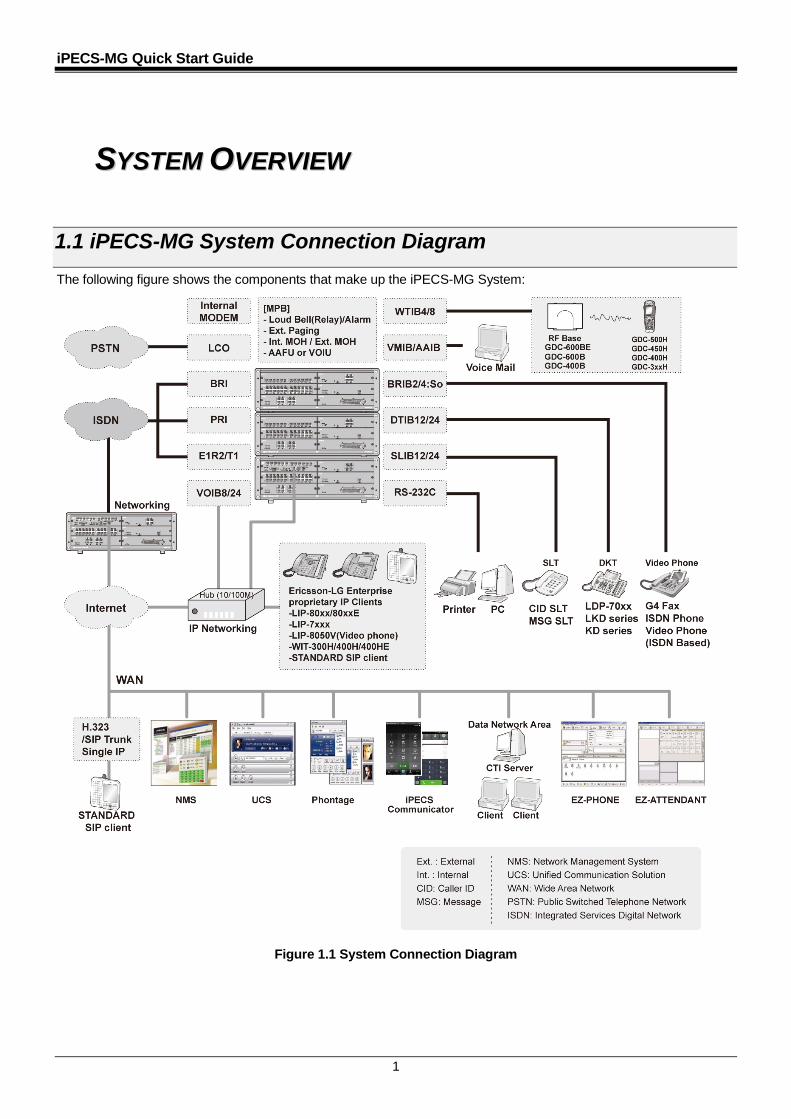
1.1 iPECS-MG System Connection Diagram The following figure shows the components that make up the iPECS-MG System:
Figure 1.1 System Connection Diagram
iPECS-MG Quick Start Guide
2
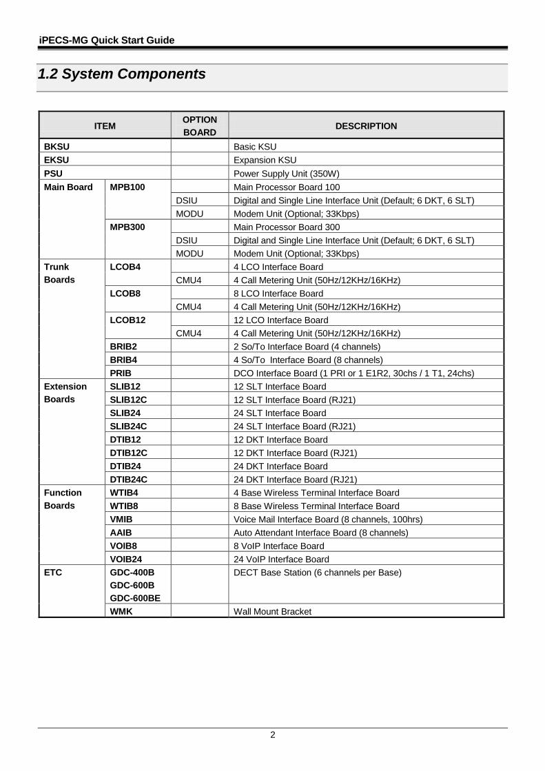
1.2 System Components
ITEM OPTION BOARD
DESCRIPTION
BKSU Basic KSU EKSU Expansion KSU PSU Power Supply Unit (350W) Main Board MPB100 Main Processor Board 100
DSIU Digital and Single Line Interface Unit (Default; 6 DKT, 6 SLT) MODU Modem Unit (Optional; 33Kbps)
MPB300 Main Processor Board 300 DSIU Digital and Single Line Interface Unit (Default; 6 DKT, 6 SLT) MODU Modem Unit (Optional; 33Kbps)
Trunk Boards
LCOB4
4 LCO Interface Board CMU4 4 Call Metering Unit (50Hz/12KHz/16KHz)
LCOB8 8 LCO Interface Board CMU4 4 Call Metering Unit (50Hz/12KHz/16KHz)
LCOB12 12 LCO Interface Board CMU4 4 Call Metering Unit (50Hz/12KHz/16KHz)
BRIB2 2 So/To Interface Board (4 channels) BRIB4 4 So/To Interface Board (8 channels) PRIB DCO Interface Board (1 PRI or 1 E1R2, 30chs / 1 T1, 24chs)
Extension Boards
SLIB12 12 SLT Interface Board SLIB12C 12 SLT Interface Board (RJ21) SLIB24 24 SLT Interface Board SLIB24C 24 SLT Interface Board (RJ21) DTIB12 12 DKT Interface Board DTIB12C 12 DKT Interface Board (RJ21) DTIB24 24 DKT Interface Board DTIB24C 24 DKT Interface Board (RJ21)
Function Boards
WTIB4 4 Base Wireless Terminal Interface Board WTIB8 8 Base Wireless Terminal Interface Board VMIB Voice Mail Interface Board (8 channels, 100hrs) AAIB Auto Attendant Interface Board (8 channels) VOIB8 8 VoIP Interface Board VOIB24 24 VoIP Interface Board
ETC GDC-400B GDC-600B GDC-600BE
DECT Base Station (6 channels per Base)
WMK Wall Mount Bracket
iPECS-MG Quick Start Guide
3
2 KKSSUU IINNSSTTAALLLLAATTIIOONN
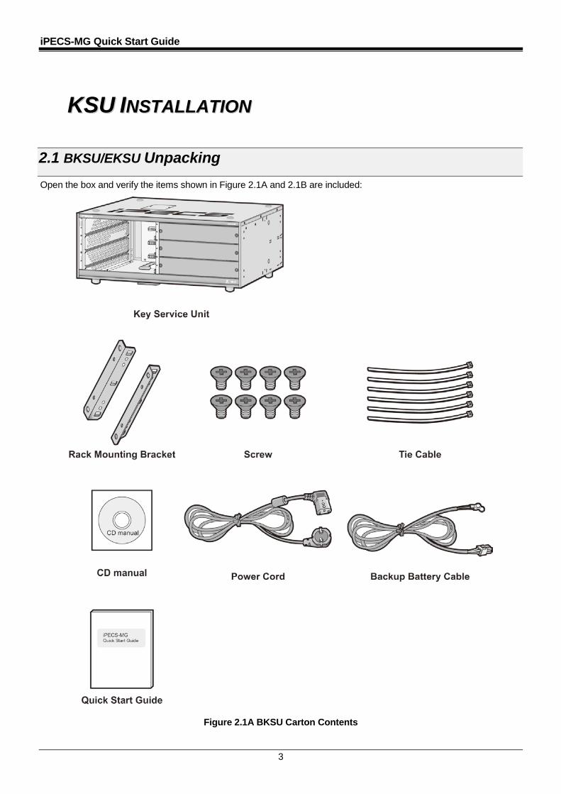
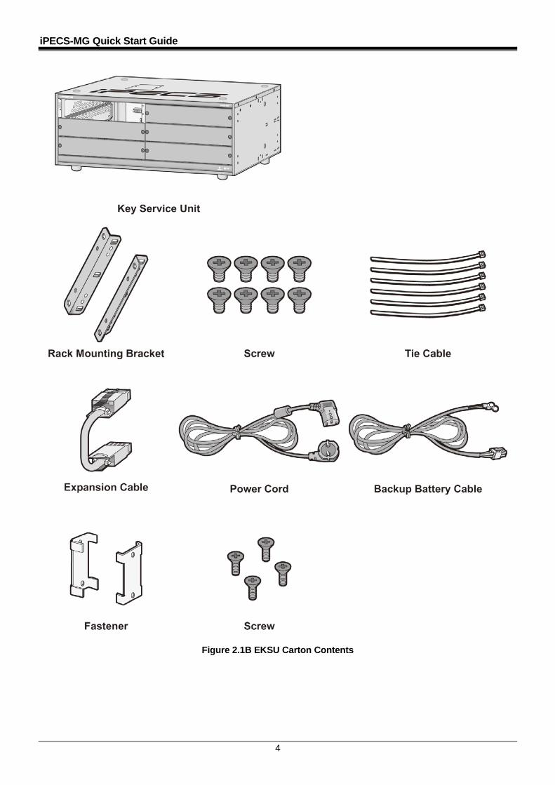
2.1 BKSU/EKSU Unpacking Open the box and verify the items shown in Figure 2.1A and 2.1B are included:
Figure 2.1A BKSU Carton Contents
iPECS-MG Quick Start Guide
4
Figure 2.1B EKSU Carton Contents
iPECS-MG Quick Start Guide
5
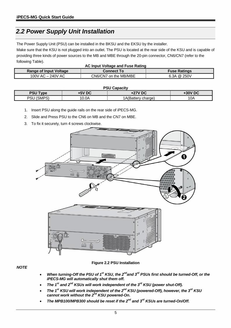
2.2 Power Supply Unit Installation
The Power Supply Unit (PSU) can be installed in the BKSU and the EKSU by the installer. Make sure that the KSU is not plugged into an outlet. The PSU is located at the rear side of the KSU and is capable of providing three kinds of power sources to the MB and MBE through the 20-pin connector, CN6/CN7 (refer to the following Table).
AC Input Voltage and Fuse Rating Range of Input Voltage Connect To Fuse Ratings
100V AC – 240V AC CN6/CN7 on the MB/MBE 6.3A @ 250V
PSU Capacity PSU Type +5V DC +27V DC +30V DC
PSU (SMPS) 10.0A 1A(Battery charge) 10A
1. Insert PSU along the guide rails on the rear side of iPECS-MG.
2. Slide and Press PSU to the CN6 on MB and the CN7 on MBE.
3. To fix it securely, turn 4 screws clockwise.
Figure 2.2 PSU Installation NOTE
• When turning-Off the PSU of 1st KSU, the 2ndand 3rd PSUs first should be turned-Off, or the iPECS-MG will automatically shut them off.
• The 1st and 2nd KSUs will work independent of the 3rd KSU (power shut-Off). • The 1st KSU will work independent of the 2nd KSU (powered-Off), however, the 3rd KSU
cannot work without the 2nd KSU powered-On. • The MPB100/MPB300 should be reset if the 2nd and 3rd KSUs are turned-On/Off.
iPECS-MG Quick Start Guide
6
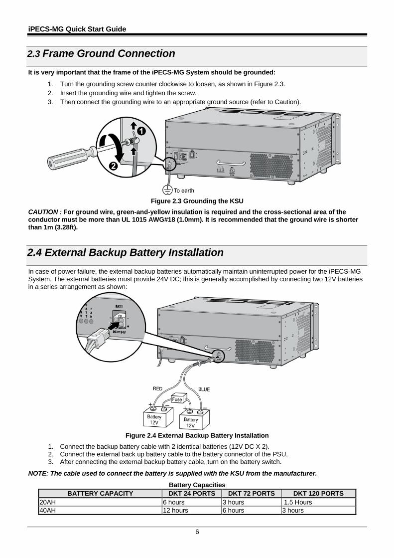
2.3 Frame Ground Connection
It is very important that the frame of the iPECS-MG System should be grounded:
1. Turn the grounding screw counter clockwise to loosen, as shown in Figure 2.3. 2. Insert the grounding wire and tighten the screw. 3. Then connect the grounding wire to an appropriate ground source (refer to Caution).
Figure 2.3 Grounding the KSU CAUTION : For ground wire, green-and-yellow insulation is required and the cross-sectional area of the conductor must be more than UL 1015 AWG#18 (1.0mm). It is recommended that the ground wire is shorter than 1m (3.28ft).
2.4 External Backup Battery Installation In case of power failure, the external backup batteries automatically maintain uninterrupted power for the iPECS-MG System. The external batteries must provide 24V DC; this is generally accomplished by connecting two 12V batteries in a series arrangement as shown:
Figure 2.4 External Backup Battery Installation 1. Connect the backup battery cable with 2 identical batteries (12V DC X 2). 2. Connect the external back up battery cable to the battery connector of the PSU. 3. After connecting the external backup battery cable, turn on the battery switch.
NOTE: The cable used to connect the battery is supplied with the KSU from the manufacturer.
Battery Capacities BATTERY CAPACITY DKT 24 PORTS DKT 72 PORTS DKT 120 PORTS
20AH 6 hours 3 hours 1.5 Hours 40AH 12 hours 6 hours 3 hours
iPECS-MG Quick Start Guide
7
2.5 KSU Mounting
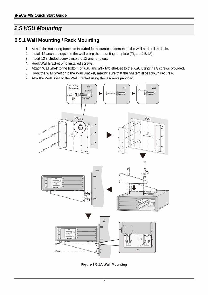
2.5.1 Wall Mounting / Rack Mounting 1. Attach the mounting template included for accurate placement to the wall and drill the hole. 2. Install 12 anchor plugs into the wall using the mounting template (Figure 2.5.1A). 3. Insert 12 included screws into the 12 anchor plugs. 4. Hook Wall Bracket onto installed screws. 5. Attach Wall Shelf to the bottom of KSU and affix two shelves to the KSU using the 8 screws provided. 6. Hook the Wall Shelf onto the Wall Bracket, making sure that the System slides down securely. 7. Affix the Wall Shelf to the Wall Bracket using the 8 screws provided.
Figure 2.5.1A Wall Mounting
iPECS-MG Quick Start Guide
8
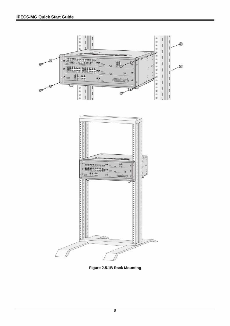
Figure 2.5.1B Rack Mounting
iPECS-MG Quick Start Guide
9
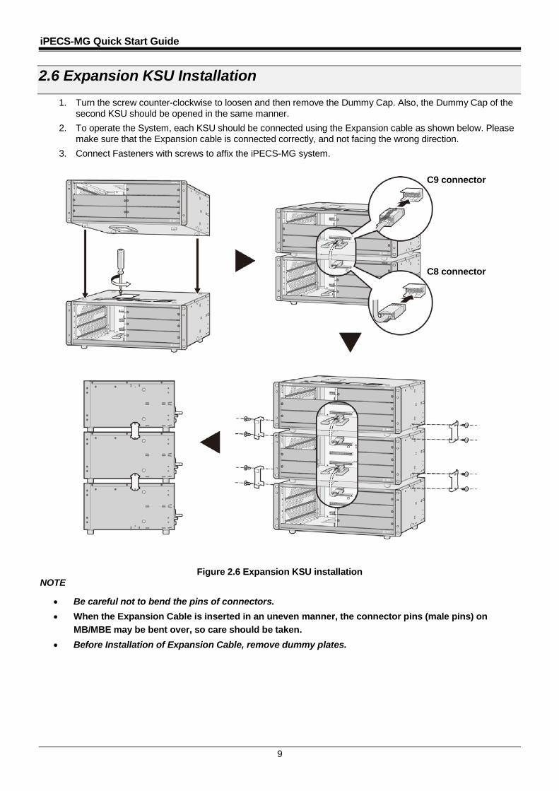
2.6 Expansion KSU Installation 1. Turn the screw counter-clockwise to loosen and then remove the Dummy Cap. Also, the Dummy Cap of the
second KSU should be opened in the same manner. 2. To operate the System, each KSU should be connected using the Expansion cable as shown below. Please
make sure that the Expansion cable is connected correctly, and not facing the wrong direction. 3. Connect Fasteners with screws to affix the iPECS-MG system.
Figure 2.6 Expansion KSU installation NOTE
• Be careful not to bend the pins of connectors. • When the Expansion Cable is inserted in an uneven manner, the connector pins (male pins) on
MB/MBE may be bent over, so care should be taken. • Before Installation of Expansion Cable, remove dummy plates.
C9 connector
C8 connector

iPECS-MG Quick Start Guide
10
3 BBOOAARRDD IINNSSTTAALLLLAATTIIOONN
3.1 Installation of the Boards Prior to installing the Boards, the following should be considered: CAUTION • Verify that electrical Power is turned OFF. • To protect the System from static electricity, do not directly touch the boards; to discharge static, touch a
grounded object, or wear a grounding strap. To install the Board, perform following Steps:
1. Slide the board along the guide rails and hold the board as shown in second figure, carefully insert the Board in the direction of the arrow so that the Board securely insert with the connector on the Mother Board.
2. Press the screw to turn it clockwise and affix it securely.
Figure 3.1 Board Installation
iPECS-MG Quick Start Guide
11
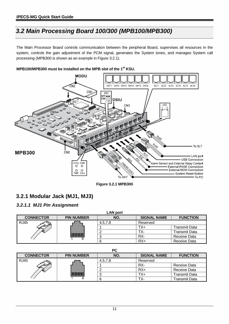
3.2 Main Processing Board 100/300 (MPB100/MPB300) The Main Processor Board controls communication between the peripheral Board, supervises all resources in the system, controls the gain adjustment of the PCM signal, generates the System tones, and manages System call processing (MPB300 is shown as an example in Figure 3.2.1). MPB100/MPB300 must be installed on the MPB slot of the 1st KSU.
Figure 3.2.1 MPB300
3.2.1 Modular Jack (MJ1, MJ3) 3.2.1.1 MJ1 Pin Assignment
LAN port CONNECTOR PIN NUMBER NO. SIGNAL NAME FUNCTION
RJ45 4,5,7,8 Reserved 1 TX+ Transmit Data 2 TX- Transmit Data 3 RX- Receive Data 6 RX+ Receive Data
PC
CONNECTOR PIN NUMBER NO. SIGNAL NAME FUNCTION RJ45 4,5,7,8 Reserved
1 RX- Receive Data 2 RX+ Receive Data 3 TX+ Transmit Data 6 TX- Transmit Data

iPECS-MG Quick Start Guide
12
3.2.1.2 MJ3 (Alarm Detection and Relay Contact) Pin Assignment MJ3
CONNECTOR PIN NUMBER NO. SIGNAL NAME RJ11 1 N/A
2 ALARM-T 3 ALARM-R 4 Relay-T 5 Relay-R 6 N/A
MJ4 Pin Assignment (USB)
CONNECTOR PIN NUMBER NO. SIGNAL NAME USB Type A
1 GND 2 D+ 3 D- 4 VBUS (+5V)
3.2.2 DSIU (Digital and Single line Interface Unit) The DSIU is included by default on the MPB100/300, and provides 6 Digital Terminal (DKT) ports and 6 Single Line analog (SLT) ports with FSK (ITU-T V.23 or Bell 202) or DTMF (ITU-T Q.23) Caller ID function. 3.2.2.1 Pin Assignment
DSIU MJ1 (DKT Only) CONNECTOR PIN NUMBER NO. SIGNAL NAME
RJ45 1,2,3 Reserved 4 DKT-T 5 DKT-R 6,7,8 Reserved
DSIU MJ2 (SLT Only)
CONNECTOR PIN NUMBER NO. SIGNAL NAME RJ45 1,2,3 Reserved
4 SLT-T 5 SLT-R 6,7,8 Reserved
3.2.3 MODU (MODEM Interface Unit) The optional MODU should be installed on the MODU connectors (CN4, CN5) of the MPB100/MPB300, and provides an analog modem connection. It supports Bell, ITU-T, V.34, V.32BIS, V.90 Protocol at a speed rate of 300bps up to 33Kbps, and automatic rate negotiation.
Figure 3.2.2 MODU
4 3 2 1
iPECS-MG Quick Start Guide
13
3.3 CO Line Boards
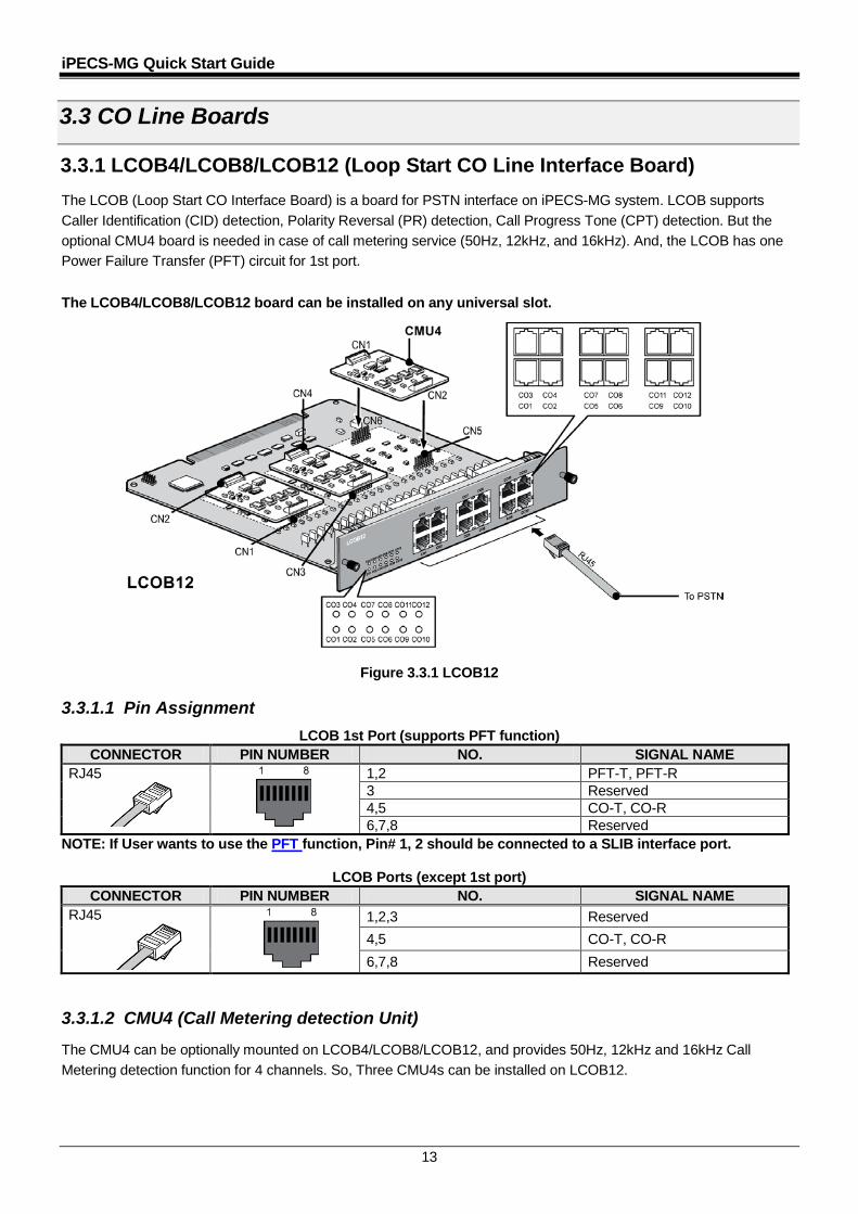
3.3.1 LCOB4/LCOB8/LCOB12 (Loop Start CO Line Interface Board) The LCOB (Loop Start CO Interface Board) is a board for PSTN interface on iPECS-MG system. LCOB supports Caller Identification (CID) detection, Polarity Reversal (PR) detection, Call Progress Tone (CPT) detection. But the optional CMU4 board is needed in case of call metering service (50Hz, 12kHz, and 16kHz). And, the LCOB has one Power Failure Transfer (PFT) circuit for 1st port.
The LCOB4/LCOB8/LCOB12 board can be installed on any universal slot.
Figure 3.3.1 LCOB12 3.3.1.1 Pin Assignment
LCOB 1st Port (supports PFT function) CONNECTOR PIN NUMBER NO. SIGNAL NAME
RJ45 1,2 PFT-T, PFT-R 3 Reserved 4,5 CO-T, CO-R 6,7,8 Reserved
NOTE: If User wants to use the PFT function, Pin# 1, 2 should be connected to a SLIB interface port.
LCOB Ports (except 1st port) CONNECTOR PIN NUMBER NO. SIGNAL NAME
RJ45 1,2,3 Reserved 4,5 CO-T, CO-R 6,7,8 Reserved
3.3.1.2 CMU4 (Call Metering detection Unit)
The CMU4 can be optionally mounted on LCOB4/LCOB8/LCOB12, and provides 50Hz, 12kHz and 16kHz Call Metering detection function for 4 channels. So, Three CMU4s can be installed on LCOB12.
iPECS-MG Quick Start Guide
14
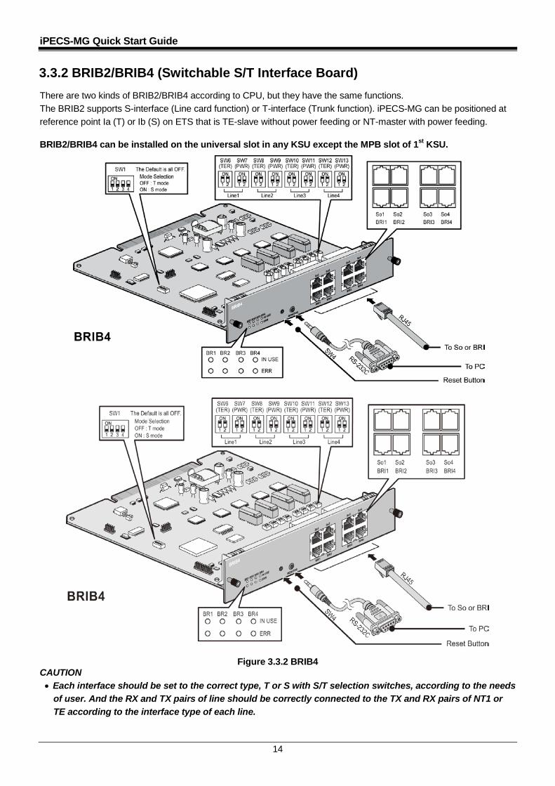
3.3.2 BRIB2/BRIB4 (Switchable S/T Interface Board) There are two kinds of BRIB2/BRIB4 according to CPU, but they have the same functions. The BRIB2 supports S-interface (Line card function) or T-interface (Trunk function). iPECS-MG can be positioned at reference point Ia (T) or Ib (S) on ETS that is TE-slave without power feeding or NT-master with power feeding. BRIB2/BRIB4 can be installed on the universal slot in any KSU except the MPB slot of 1st KSU.
Figure 3.3.2 BRIB4 CAUTION • Each interface should be set to the correct type, T or S with S/T selection switches, according to the needs
of user. And the RX and TX pairs of line should be correctly connected to the TX and RX pairs of NT1 or TE according to the interface type of each line.
iPECS-MG Quick Start Guide
15
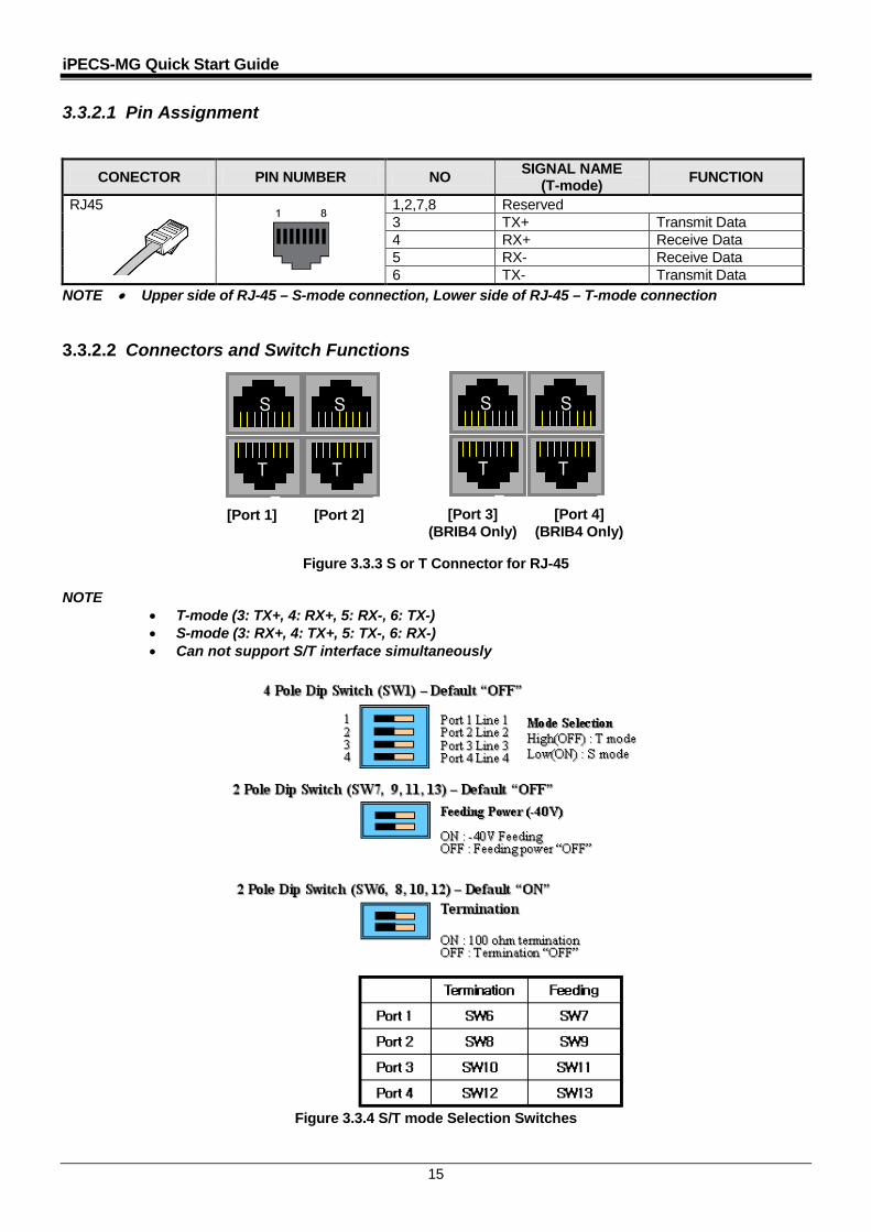
3.3.2.1 Pin Assignment
CONECTOR PIN NUMBER NO SIGNAL NAME (T-mode) FUNCTION
RJ45 1,2,7,8 Reserved 3 TX+ Transmit Data 4 RX+ Receive Data 5 RX- Receive Data 6 TX- Transmit Data
NOTE • Upper side of RJ-45 – S-mode connection, Lower side of RJ-45 – T-mode connection 3.3.2.2 Connectors and Switch Functions
Figure 3.3.3 S or T Connector for RJ-45
NOTE • T-mode (3: TX+, 4: RX+, 5: RX-, 6: TX-) • S-mode (3: RX+, 4: TX+, 5: TX-, 6: RX-) • Can not support S/T interface simultaneously
Figure 3.3.4 S/T mode Selection Switches
S S
T T [Port 1] [Port 2]
S S
T T
[Port 3] (BRIB4 Only)
[Port 4] (BRIB4 Only)
T T T T
iPECS-MG Quick Start Guide
16
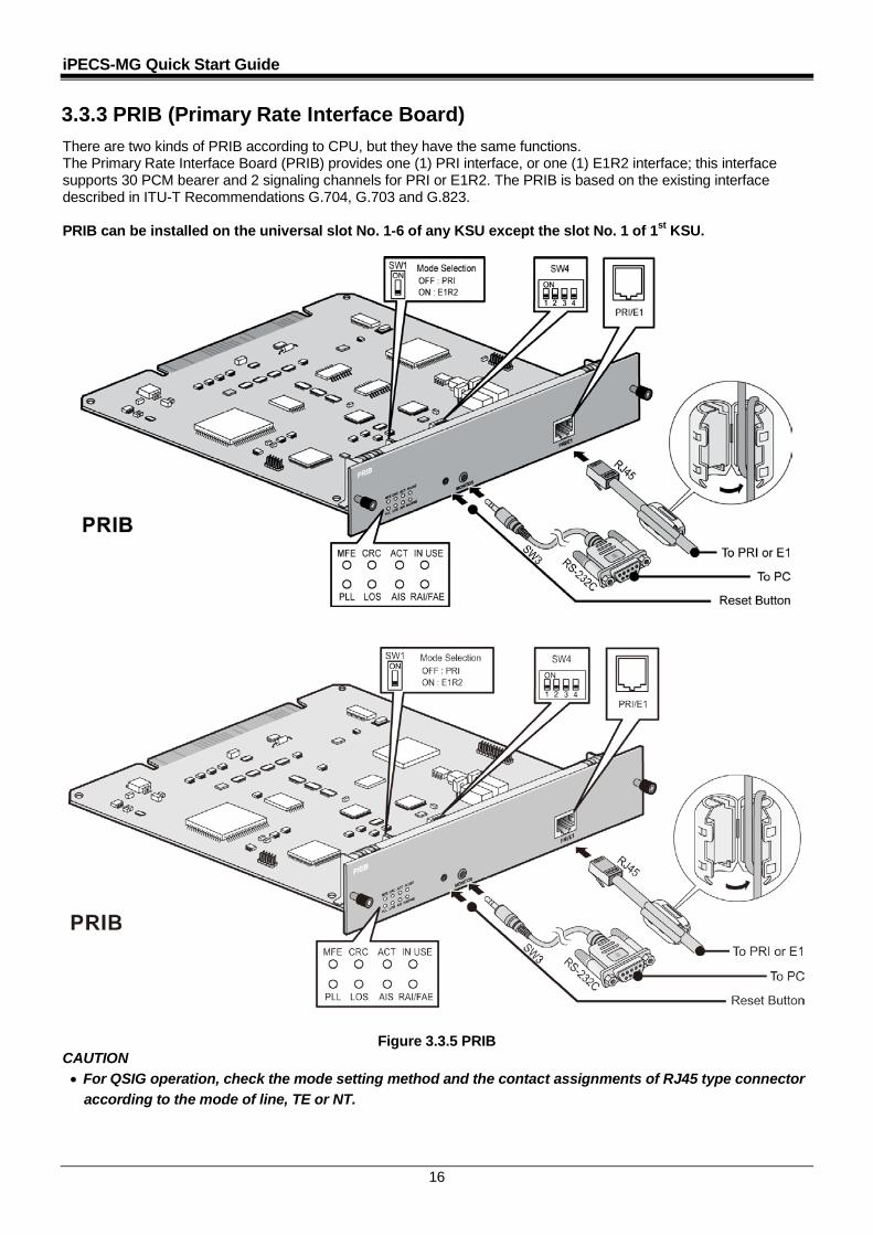
3.3.3 PRIB (Primary Rate Interface Board) There are two kinds of PRIB according to CPU, but they have the same functions. The Primary Rate Interface Board (PRIB) provides one (1) PRI interface, or one (1) E1R2 interface; this interface supports 30 PCM bearer and 2 signaling channels for PRI or E1R2. The PRIB is based on the existing interface described in ITU-T Recommendations G.704, G.703 and G.823. PRIB can be installed on the universal slot No. 1-6 of any KSU except the slot No. 1 of 1st KSU.
Figure 3.3.5 PRIB CAUTION • For QSIG operation, check the mode setting method and the contact assignments of RJ45 type connector
according to the mode of line, TE or NT.
iPECS-MG Quick Start Guide
17
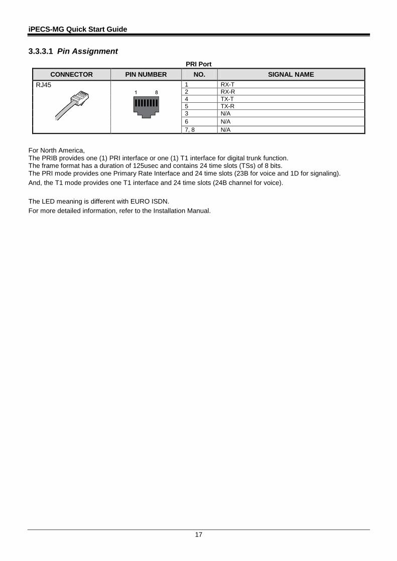
3.3.3.1 Pin Assignment PRI Port
CONNECTOR PIN NUMBER NO. SIGNAL NAME RJ45
1 RX-T 2 RX-R 4 TX-T 5 TX-R 3 N/A 6 N/A 7, 8 N/A
For North America, The PRIB provides one (1) PRI interface or one (1) T1 interface for digital trunk function. The frame format has a duration of 125usec and contains 24 time slots (TSs) of 8 bits. The PRI mode provides one Primary Rate Interface and 24 time slots (23B for voice and 1D for signaling). And, the T1 mode provides one T1 interface and 24 time slots (24B channel for voice). The LED meaning is different with EURO ISDN. For more detailed information, refer to the Installation Manual.
iPECS-MG Quick Start Guide
18
3.4 Extension Boards
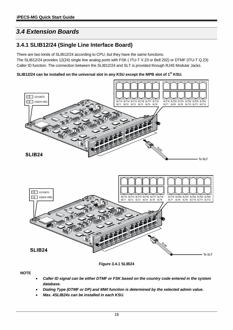
3.4.1 SLIB12/24 (Single Line Interface Board) There are two kinds of SLIB12/24 according to CPU, but they have the same functions. The SLIB12/24 provides 12(24) single line analog ports with FSK ( ITU-T V.23 or Bell 202) or DTMF (ITU-T Q.23) Caller ID function. The connection between the SLIB12/24 and SLT is provided through RJ45 Modular Jacks. SLIB12/24 can be installed on the universal slot in any KSU except the MPB slot of 1st KSU.
Figure 3.4.1 SLIB24
NOTE • Caller ID signal can be either DTMF or FSK based on the country code entered in the system
database. • Dialing Type (DTMF or DP) and MWI function is determined by the selected admin value. • Max. 4SLIB24s can be installed in each KSU.
iPECS-MG Quick Start Guide
19
3.4.1.1 Pin Assignment SLIB12/24
CONNECTOR PIN NUMBER NO SIGNAL NAME FUNCTION RJ45 1,2,3 Reserved
4 SLT_RX Receive Data 5 SLT_TX Transmit Data 6,7,8 Reserved
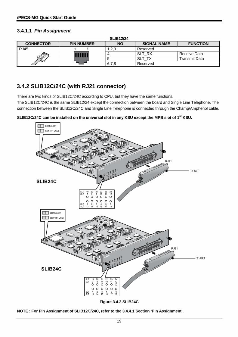
3.4.2 SLIB12C/24C (with RJ21 connector) There are two kinds of SLIB12C/24C according to CPU, but they have the same functions. The SLIB12C/24C is the same SLIB12/24 except the connection between the board and Single Line Telephone. The connection between the SLIB12C/24C and Single Line Telephone is connected through the Champ/Amphenol cable. SLIB12C/24C can be installed on the universal slot in any KSU except the MPB slot of 1st KSU.
Figure 3.4.2 SLIB24C NOTE : For Pin Assignment of SLIB12C/24C, refer to the 3.4.4.1 Section ‘Pin Assignment’.
iPECS-MG Quick Start Guide
20
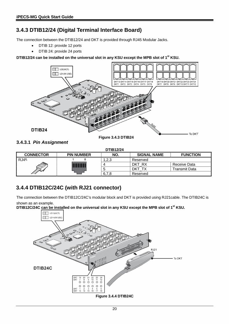
3.4.3 DTIB12/24 (Digital Terminal Interface Board) The connection between the DTIB12/24 and DKT is provided through RJ45 Modular Jacks.
• DTIB 12: provide 12 ports • DTIB 24: provide 24 ports
DTIB12/24 can be installed on the universal slot in any KSU except the MPB slot of 1st KSU.
Figure 3.4.3 DTIB24 3.4.3.1 Pin Assignment
DTIB12/24 CONNECTOR PIN NUMBER NO. SIGNAL NAME FUNCTION
RJ45 1,2,3 Reserved 4 DKT_RX Receive Data 5 DKT_TX Transmit Data 6,7,8 Reserved
3.4.4 DTIB12C/24C (with RJ21 connector) The connection between the DTIB12C/24C’s modular block and DKT is provided using RJ21cable. The DTIB24C is shown as an example. DTIB12C/24C can be installed on the universal slot in any KSU except the MPB slot of 1st KSU.
Figure 3.4.4 DTIB24C

iPECS-MG Quick Start Guide
21
3.4.4.1 Pin Assignment SLIB12C/24C/DTIB12C/24C
CONNECTOR TYPE
PIN NUMBER
RJ21 PIN
PAIR PIN COLOR CODE
SLIB/DTIB(12/24C) DESIGNATION
PORT NO
REMARKS
RJ21 1 1 1 VT-1 1 BL:BLUE BK:BLACK BN:BROWN OR:ORANGE WH:WHITE GN:GREEN SL: SILVER VI:VIOLET RD:RED YL:YELLOW
26 26 VR-1 2 2 2 VT-2 2 27 27 VR-2 3 3 3 VT-3 3 28 28 VR-3 4 4 4 VT-4 4 29 29 VR-4 5 5 5 VT-5 5 30 30 VR-5 6 6 6 VT-6 6 31 31 VR-6 7 7 7 VT-7 7 32 32 VR-7 8 8 8 VT-8 8 33 33 VR-8 9 9 9 VT-9 9 34 34 VR-9 10 10 10 VT-10 10 35 35 VR-10 11 11 11 VT-11 11 36 36 VR-11 12 37
12 12 37
VT-12 VR-12
12
13 38
13 13 38
VT-13 VR-13
13
14 39
14 14 39
VT-14 VR-14
14
15 40
15 15 40
VT-15 VR-15
15
16 41
16 16 41
VT-16 VR-16
16
17 42
17 17 42
VT-17 VR-17
17
18 43
18 18 43
VT-18 VR-18
18
19 44
19 19 44
VT-19 VR-19
19
20 45
20 20 45
VT-20 VR-20
20
21 46
21 21 46
VT-21 VR-21
21
22 47
22 22 47
VT-22 VR-22
22
23 48
23 23 48
VT-23 VR-23
23
24 24 24 VT-24 24 49 49 VR-24
iPECS-MG Quick Start Guide
22
3.5 Function Boards
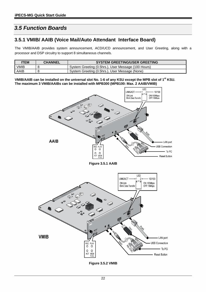
3.5.1 VMIB/ AAIB (Voice Mail/Auto Attendant Interface Board) The VMIB/AAIB provides system announcement, ACD/UCD announcement, and User Greeting, along with a processor and DSP circuitry to support 8 simultaneous channels.
ITEM CHANNEL SYSTEM GREETING/USER GREETING VMIB 8 System Greeting (0.5hrs.), User Message (100 Hours) AAIB 8 System Greeting (0.5hrs.), User Message (None)
VMIB/AAIB can be installed on the universal slot No. 1-6 of any KSU except the MPB slot of 1st KSU. The maximum 3 VMIB/AAIBs can be installed with MPB300 (MPB100: Max. 2 AAIB/VMIB)
Figure 3.5.1 AAIB
Figure 3.5.2 VMIB

iPECS-MG Quick Start Guide
23
3.5.1.1 Pin Assignment LAN Port
CONNECTOR PIN NUMBER NO. SIGNAL NAME FUNCTION RJ45 4,5,7,8 RESERVED
1 TX+ Transmit Data 2 TX- Transmit Data 3 RX- Receive Data 6 RX+ Receive Data
USB Port CONNECTOR PIN NUMBER NO. SIGNAL NAME
USB Type A
1 GND 2 D+ 3 D- 4 VBUS (+5V)
3.5.2 VOIB8/24 (Voice over Internet protocol Board 8ch./ 24ch.) The VOIB8/VOIB24 provides the Ethernet interface for S/W applications and VoIP features. The VOIB8/24 is used to provide packet relay for remote devices to communicate with the host and translate between the iPECS proprietary protocols and other standard protocols (H323, SIP).
ITEM CHANNEL REMARK VOIB8 8 VOIB24 24
VOIB8/VOIB24 can be installed on the universal slot No. 1-6 of any KSU except slot No. 1 of 1st KSU.
Figure 3.5.3 VOIB24 3.5.2.1 Pin Assignment
LAN Port CONNECTOR PIN NUMBER NO. SIGNAL NAME FUNCTION
RJ45
4,5,7,8 RESERVED 1 TX+ Transmit Data 2 TX- Transmit Data 3 RX- Receive Data 6 RX+ Receive Data
4 3 2 1
iPECS-MG Quick Start Guide
24
3.6 Terminal and Door Phone Models
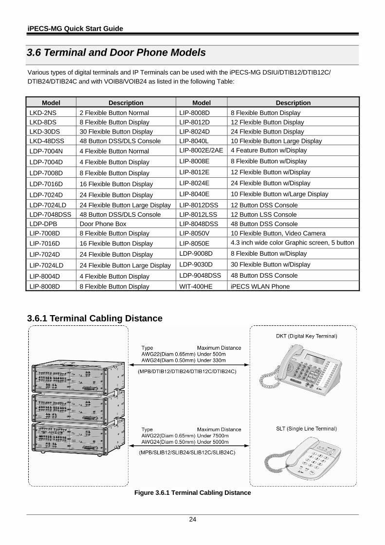
Various types of digital terminals and IP Terminals can be used with the iPECS-MG DSIU/DTIB12/DTIB12C/
DTIB24/DTIB24C and with VOIB8/VOIB24 as listed in the following Table:
Model Description Model Description
LKD-2NS 2 Flexible Button Normal LIP-8008D 8 Flexible Button Display
LKD-8DS 8 Flexible Button Display LIP-8012D 12 Flexible Button Display
LKD-30DS 30 Flexible Button Display LIP-8024D 24 Flexible Button Display
LKD-48DSS 48 Button DSS/DLS Console LIP-8040L 10 Flexible Button Large Display
LDP-7004N 4 Flexible Button Normal LIP-8002E/2AE 4 Feature Button w/Display
LDP-7004D 4 Flexible Button Display LIP-8008E 8 Flexible Button w/Display
LDP-7008D 8 Flexible Button Display LIP-8012E 12 Flexible Button w/Display
LDP-7016D 16 Flexible Button Display LIP-8024E 24 Flexible Button w/Display
LDP-7024D 24 Flexible Button Display LIP-8040E 10 Flexible Button w/Large Display
LDP-7024LD 24 Flexible Button Large Display LIP-8012DSS 12 Button DSS Console
LDP-7048DSS 48 Button DSS/DLS Console LIP-8012LSS 12 Button LSS Console
LDP-DPB Door Phone Box LIP-8048DSS 48 Button DSS Console
LIP-7008D 8 Flexible Button Display LIP-8050V 10 Flexible Button, Video Camera
LIP-7016D 16 Flexible Button Display LIP-8050E 4.3 inch wide color Graphic screen, 5 button
LIP-7024D 24 Flexible Button Display LDP-9008D 8 Flexible Button w/Display
LIP-7024LD 24 Flexible Button Large Display LDP-9030D 30 Flexible Button w/Display
LIP-8004D 4 Flexible Button Display LDP-9048DSS 48 Button DSS Console
LIP-8008D 8 Flexible Button Display WIT-400HE iPECS WLAN Phone
3.6.1 Terminal Cabling Distance
Figure 3.6.1 Terminal Cabling Distance
iPECS-MG Quick Start Guide
25
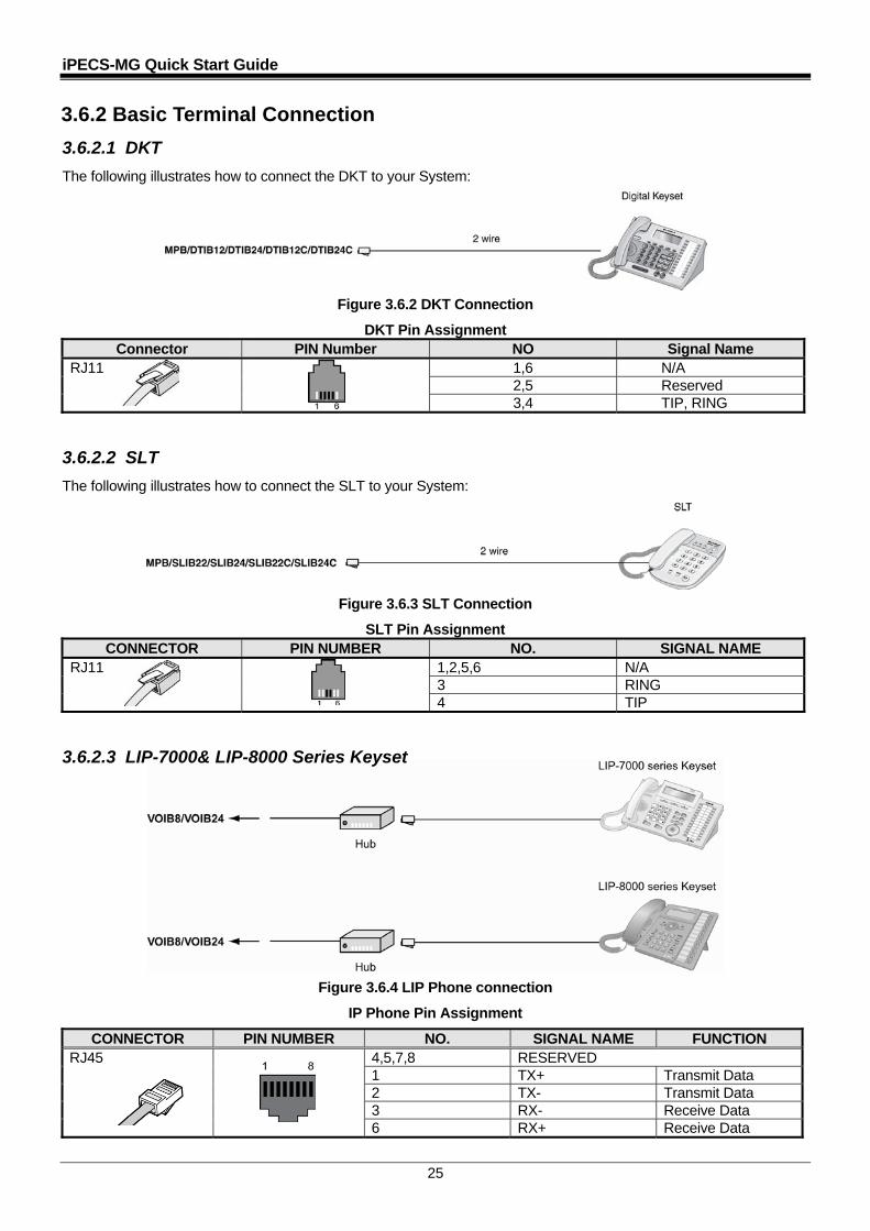
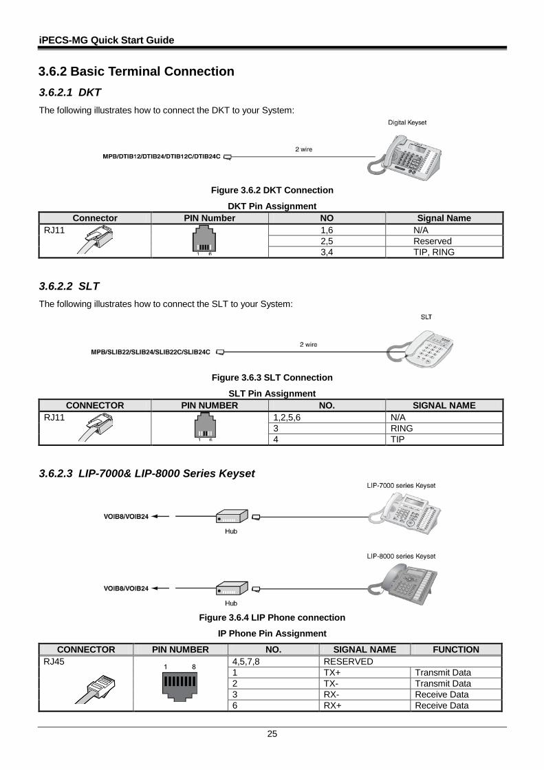
3.6.2 Basic Terminal Connection
3.6.2.1 DKT
The following illustrates how to connect the DKT to your System:
Figure 3.6.2 DKT Connection
DKT Pin Assignment Connector PIN Number NO Signal Name
RJ11 1,6 N/A 2,5 Reserved 3,4 TIP, RING
3.6.2.2 SLT
The following illustrates how to connect the SLT to your System:
Figure 3.6.3 SLT Connection
SLT Pin Assignment CONNECTOR PIN NUMBER NO. SIGNAL NAME
RJ11 1,2,5,6 N/A 3 RING 4 TIP
3.6.2.3 LIP-7000& LIP-8000 Series Keyset
Figure 3.6.4 LIP Phone connection
IP Phone Pin Assignment
CONNECTOR PIN NUMBER NO. SIGNAL NAME FUNCTION RJ45 4,5,7,8 RESERVED
1 TX+ Transmit Data 2 TX- Transmit Data 3 RX- Receive Data 6 RX+ Receive Data
iPECS-MG Quick Start Guide
25
3.6.2 Basic Terminal Connection 3.6.2.1 DKT The following illustrates how to connect the DKT to your System:
Figure 3.6.2 DKT Connection
DKT Pin Assignment Connector PIN Number NO Signal Name
RJ11 1,6 N/A 2,5 Reserved 3,4 TIP, RING
3.6.2.2 SLT The following illustrates how to connect the SLT to your System:
Figure 3.6.3 SLT Connection
SLT Pin Assignment CONNECTOR PIN NUMBER NO. SIGNAL NAME
RJ11 1,2,5,6 N/A 3 RING 4 TIP
3.6.2.3 LIP-7000& LIP-8000 Series Keyset
Figure 3.6.4 LIP Phone connection
IP Phone Pin Assignment
CONNECTOR PIN NUMBER NO. SIGNAL NAME FUNCTION RJ45 4,5,7,8 RESERVED
1 TX+ Transmit Data 2 TX- Transmit Data 3 RX- Receive Data 6 RX+ Receive Data
iPECS-MG Quick Start Guide
26
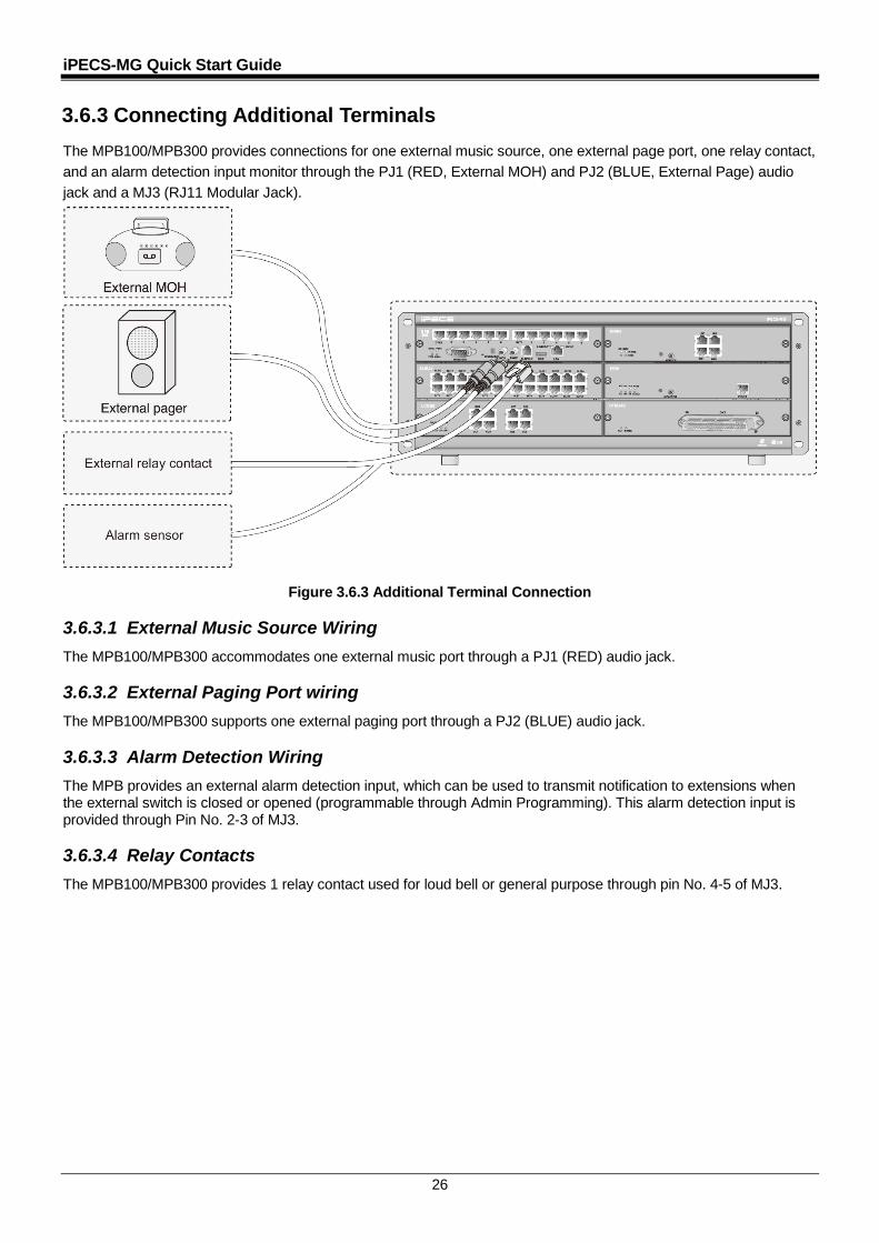
3.6.3 Connecting Additional Terminals The MPB100/MPB300 provides connections for one external music source, one external page port, one relay contact, and an alarm detection input monitor through the PJ1 (RED, External MOH) and PJ2 (BLUE, External Page) audio jack and a MJ3 (RJ11 Modular Jack).
Figure 3.6.3 Additional Terminal Connection 3.6.3.1 External Music Source Wiring The MPB100/MPB300 accommodates one external music port through a PJ1 (RED) audio jack. 3.6.3.2 External Paging Port wiring The MPB100/MPB300 supports one external paging port through a PJ2 (BLUE) audio jack. 3.6.3.3 Alarm Detection Wiring The MPB provides an external alarm detection input, which can be used to transmit notification to extensions when the external switch is closed or opened (programmable through Admin Programming). This alarm detection input is provided through Pin No. 2-3 of MJ3. 3.6.3.4 Relay Contacts The MPB100/MPB300 provides 1 relay contact used for loud bell or general purpose through pin No. 4-5 of MJ3.
iPECS-MG Quick Start Guide
27
4 DDEECCTT IINNSSTTAALLLLAATTIIOONN
4.1 Introduction
The iPECS-MG provides support for the System DECT solution which is composed WTIB4/8, Base Station (GDC-400B & GDC-600B & GDC-600BE), and DECT terminals (GDC-33xH, 34xH, 4x0H/500H). For installation instructions, refer to the iPECS DECT Installation Guide.
4.2 Board Installation
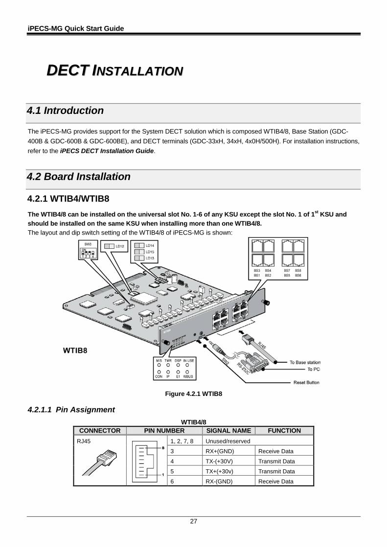
4.2.1 WTIB4/WTIB8 The WTIB4/8 can be installed on the universal slot No. 1-6 of any KSU except the slot No. 1 of 1st KSU and should be installed on the same KSU when installing more than one WTIB4/8. The layout and dip switch setting of the WTIB4/8 of iPECS-MG is shown:
Figure 4.2.1 WTIB8 4.2.1.1 Pin Assignment
WTIB4/8 CONNECTOR PIN NUMBER SIGNAL NAME FUNCTION
RJ45 1, 2, 7, 8 Unused/reserved
3 RX+(GND) Receive Data
4 TX-(+30V) Transmit Data
5 TX+(+30v) Transmit Data
6 RX-(GND) Receive Data
iPECS-MG Quick Start Guide
28
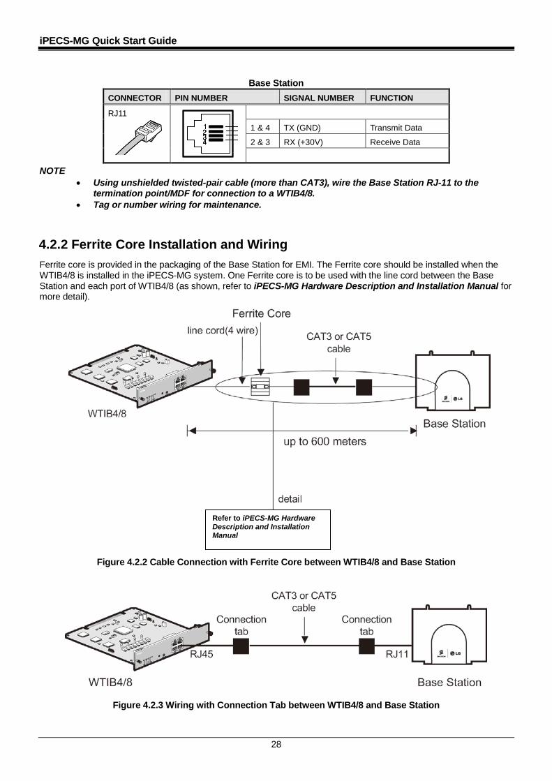
Base Station
CONNECTOR PIN NUMBER SIGNAL NUMBER FUNCTION
RJ11
1 & 4 TX (GND) Transmit Data
2 & 3 RX (+30V) Receive Data
NOTE • Using unshielded twisted-pair cable (more than CAT3), wire the Base Station RJ-11 to the
termination point/MDF for connection to a WTIB4/8. • Tag or number wiring for maintenance.
4.2.2 Ferrite Core Installation and Wiring Ferrite core is provided in the packaging of the Base Station for EMI. The Ferrite core should be installed when the WTIB4/8 is installed in the iPECS-MG system. One Ferrite core is to be used with the line cord between the Base Station and each port of WTIB4/8 (as shown, refer to iPECS-MG Hardware Description and Installation Manual for more detail).
Figure 4.2.2 Cable Connection with Ferrite Core between WTIB4/8 and Base Station
Figure 4.2.3 Wiring with Connection Tab between WTIB4/8 and Base Station
1234
1234
1234
1234
Refer to iPECS-MG Hardware Description and Installation Manual
iPECS-MG Quick Start Guide
29
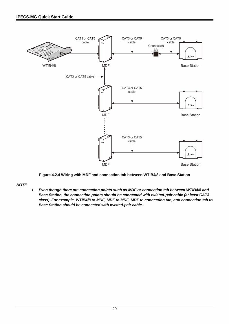
Figure 4.2.4 Wiring with MDF and connection tab between WTIB4/8 and Base Station NOTE
• Even though there are connection points such as MDF or connection tab between WTIB4/8 and Base Station, the connection points should be connected with twisted-pair cable (at least CAT3 class). For example, WTIB4/8 to MDF, MDF to MDF, MDF to connection tab, and connection tab to Base Station should be connected with twisted-pair cable.

iPECS-MG Quick Start Guide
30
5 SSTTAARRTTIINNGG TTHHEE IIPPEECCSS--MMGG
5.1 Before Starting the iPECS-MG System
The first step in starting the newly installed iPECS-MG system is initializing the databases. The following procedure
describes the necessary Steps:
1) Verify MPB100/MPB300 has been inserted into the MPB slot of the first KSU.
- Before programming the System, Switch 1-1 pole should be OFF and then power cycle OFF and ON to
initialize the default System database.
2) Plug the AC power cord into the iPECS-MG System and AC outlet. Turn on the iPECS-MG System; after
installing the 1st, 2nd and 3rd KSUs, Power-On as follows:
- Order of Power-On Procedure: 3rd KSU 2nd KSU 1st KSU.
- After KSU(s) have been turned-On, you have to reset the MPB100/MPB300 in the 1st KSU.
3) Once the database has been initialized, switch 1-1 should be placed in the ON position to protect the User
database and to protect the features being programmed in Admin. programming.
4) Switch 1-2 should be placed in the ON position to feed the Lithium Battery Voltage to SRAM/RTC directly
(protects the User Database and System Time/Date information, etc.).
5.2 Basic Programming
The iPECS-MG System can be programmed to meet an individual customer’s needs. There are two ways to perform Admin Programming:
• Web Admin Programming • DKT Programming
5.2.1 Web Admin Programming NOTE
• For complete instructions on using the Web Admin, refer to the iPECS-MG Web Administration Manual.
Upon entering WEB Admin Programming mode, the default System IP Address is the ’10.10.10.1’. The IP Address can be changed using PGM108 in Keyset programming or with the IP configuration command in maintenance mode. Another way is to connect the PC to MPB with LAN cable and configure the PC IP address to ’10.10.10.xx’, and PC gateway address to ’10.10.10.254’.

iPECS-MG Quick Start Guide
31
5.2.1.1 How to enter the Web Admin Programming
1) In the browser ‘ADDRESS’ field, enter the MPB IP address (default 10.10.10.1), and then the WEB server returns to the WEB Services Home page.
2) On the Home page, click [Admin & Maintenance] to login to the Web-admin. If user id, password is assigned, enter the appropriate user id, password.
1)
2)
iPECS-MG Quick Start Guide
32
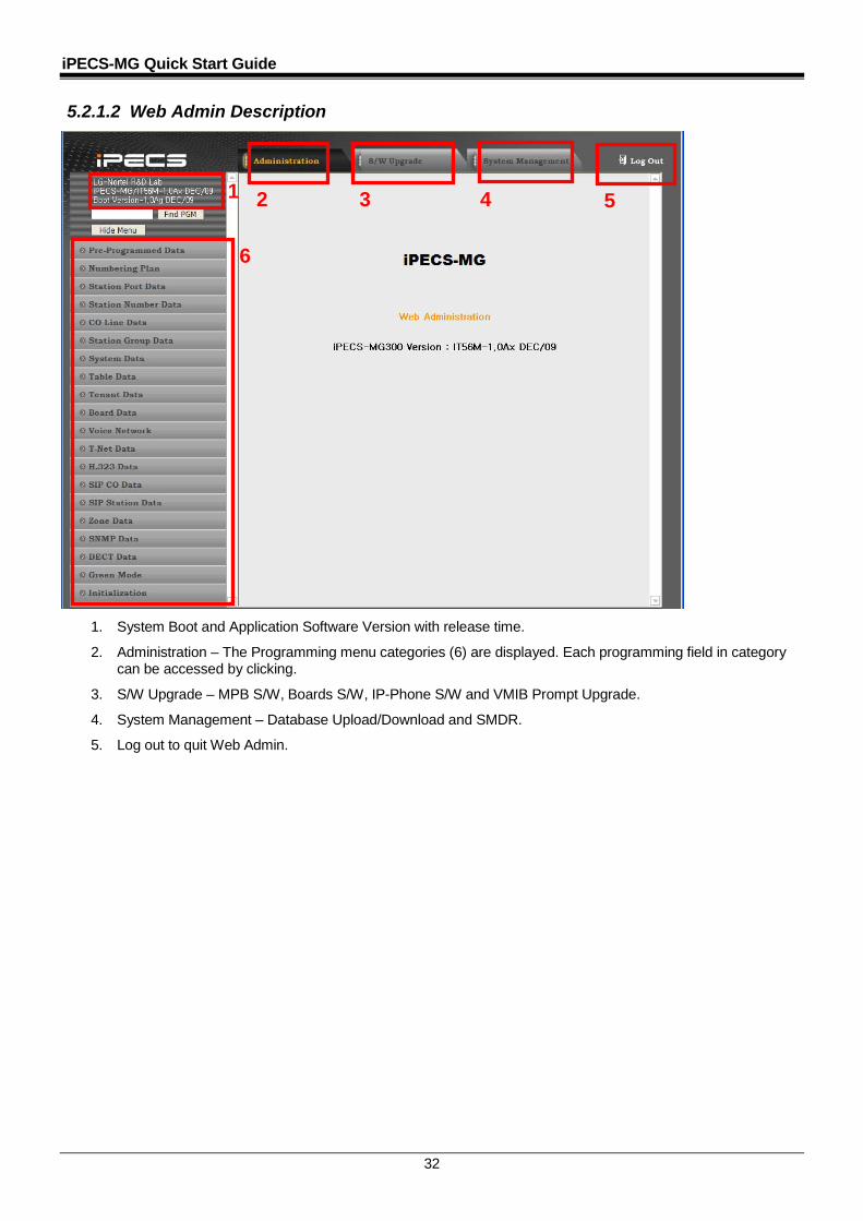
5.2.1.2 Web Admin Description
1. System Boot and Application Software Version with release time.
2. Administration – The Programming menu categories (6) are displayed. Each programming field in category can be accessed by clicking.
3. S/W Upgrade – MPB S/W, Boards S/W, IP-Phone S/W and VMIB Prompt Upgrade.
4. System Management – Database Upload/Download and SMDR.
5. Log out to quit Web Admin.
1 2
3
4
5
6
iPECS-MG Quick Start Guide
33
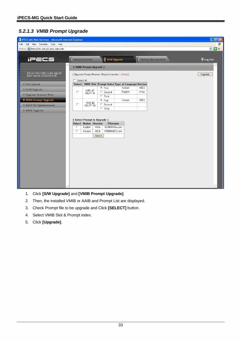
5.2.1.3 VMIB Prompt Upgrade
1. Click [S/W Upgrade] and [VMIB Prompt Upgrade].
2. Then, the installed VMIB or AAIB and Prompt List are displayed.
3. Check Prompt file to be upgrade and Click [SELECT] button.
4. Select VMIB Slot & Prompt index.
5. Click [Upgrade].
iPECS-MG Quick Start Guide
34
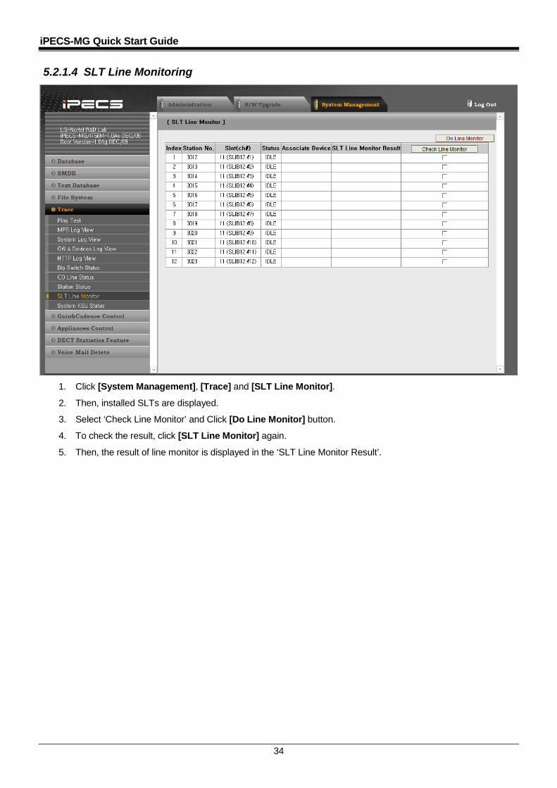
5.2.1.4 SLT Line Monitoring
1. Click [System Management], [Trace] and [SLT Line Monitor].
2. Then, installed SLTs are displayed.
3. Select ‘Check Line Monitor’ and Click [Do Line Monitor] button.
4. To check the result, click [SLT Line Monitor] again.
5. Then, the result of line monitor is displayed in the ‘SLT Line Monitor Result’.

iPECS-MG Quick Start Guide
35
5.2.2 DKT Programming 5.2.2.1 How to Enter Programming Mode To enter programming mode, perform the following Steps:
1. Lift handset or press the [MON] button on the ADMIN station; the ICM dial tone (optional) will be presented.
2. Press the [TRANS/PGM] button and dial *#; the confirmation tone will be heard.
3. Enter the ADMIN password (if applicable); the station will be in ADMIN programming mode (confirmation tone is heard).
4. Each program is accessed by pressing the [TRANS/PGM] button; the following will display:
5. Enter the three-digit program number; if an error is made while entering data, the [TRANS/PGM] button will return to the previous status.
NOTE
• To return the previous state while ADMIN programming, press the [CONF] button; pressing the [CONF] button will clear the temporary data fields.
5.2.2.2 Permanent Update Procedure
To commit programmed data to permanent memory, perform the following Steps: 1. When data has been entered, press the [HOLD/SAVE] button to store the data permanently; if all data
was entered correctly, a confirmation tone will be heard. 2. If there were any errors in the entry, an error tone will be presented and data is not stored in the permanent
memory, and the terminal will return to the previous state. 5.2.2.3 How to Reset the System
To reset the system: 1. Press the [Trans/PGM] button. 2. Dial 499 (Reset System Code). 3. Press the FLEX2 button. 4. Press [HOLD/SAVE].
NOTE
• The system also should be reset after entering PGM100 – FLEX 1 (Nation Code Assignment).
ENTER PGM NUMBER
iPECS-MG Quick Start Guide
36
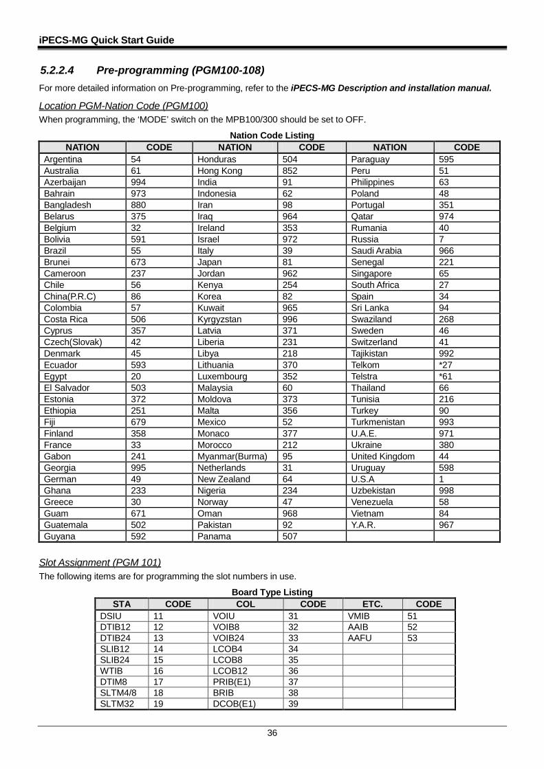
5.2.2.4 Pre-programming (PGM100-108) For more detailed information on Pre-programming, refer to the iPECS-MG Description and installation manual.
Location PGM-Nation Code (PGM100) When programming, the ‘MODE’ switch on the MPB100/300 should be set to OFF.
Nation Code Listing NATION CODE NATION CODE NATION CODE
Argentina 54 Honduras 504 Paraguay 595 Australia 61 Hong Kong 852 Peru 51 Azerbaijan 994 India 91 Philippines 63 Bahrain 973 Indonesia 62 Poland 48 Bangladesh 880 Iran 98 Portugal 351 Belarus 375 Iraq 964 Qatar 974 Belgium 32 Ireland 353 Rumania 40 Bolivia 591 Israel 972 Russia 7 Brazil 55 Italy 39 Saudi Arabia 966 Brunei 673 Japan 81 Senegal 221 Cameroon 237 Jordan 962 Singapore 65 Chile 56 Kenya 254 South Africa 27 China(P.R.C) 86 Korea 82 Spain 34 Colombia 57 Kuwait 965 Sri Lanka 94 Costa Rica 506 Kyrgyzstan 996 Swaziland 268 Cyprus 357 Latvia 371 Sweden 46 Czech(Slovak) 42 Liberia 231 Switzerland 41 Denmark 45 Libya 218 Tajikistan 992 Ecuador 593 Lithuania 370 Telkom *27 Egypt 20 Luxembourg 352 Telstra *61 El Salvador 503 Malaysia 60 Thailand 66 Estonia 372 Moldova 373 Tunisia 216 Ethiopia 251 Malta 356 Turkey 90 Fiji 679 Mexico 52 Turkmenistan 993 Finland 358 Monaco 377 U.A.E. 971 France 33 Morocco 212 Ukraine 380 Gabon 241 Myanmar(Burma) 95 United Kingdom 44 Georgia 995 Netherlands 31 Uruguay 598 German 49 New Zealand 64 U.S.A 1 Ghana 233 Nigeria 234 Uzbekistan 998 Greece 30 Norway 47 Venezuela 58 Guam 671 Oman 968 Vietnam 84 Guatemala 502 Pakistan 92 Y.A.R. 967 Guyana 592 Panama 507
Slot Assignment (PGM 101) The following items are for programming the slot numbers in use.
Board Type Listing STA CODE COL CODE ETC. CODE
DSIU 11 VOIU 31 VMIB 51 DTIB12 12 VOIB8 32 AAIB 52 DTIB24 13 VOIB24 33 AAFU 53 SLIB12 14 LCOB4 34 SLIB24 15 LCOB8 35 WTIB 16 LCOB12 36 DTIM8 17 PRIB(E1) 37 SLTM4/8 18 BRIB 38 SLTM32 19 DCOB(E1) 39
iPECS-MG Quick Start Guide
37
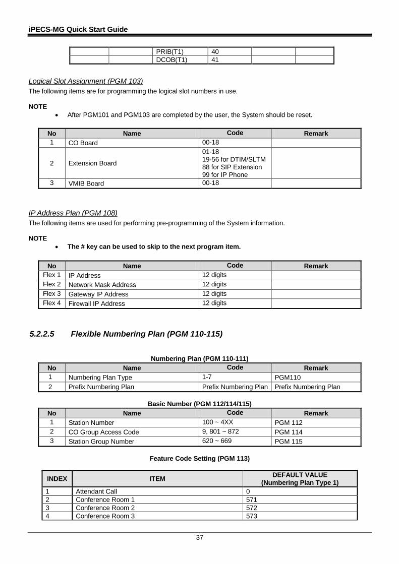
PRIB(T1) 40 DCOB(T1) 41
Logical Slot Assignment (PGM 103) The following items are for programming the logical slot numbers in use. NOTE
• After PGM101 and PGM103 are completed by the user, the System should be reset.
No Name Code Remark 1 CO Board 00-18
2 Extension Board
01-18 19-56 for DTIM/SLTM 88 for SIP Extension 99 for IP Phone
3 VMIB Board 00-18
IP Address Plan (PGM 108) The following items are used for performing pre-programming of the System information. NOTE
• The # key can be used to skip to the next program item.
No Name Code Remark Flex 1 IP Address 12 digits Flex 2 Network Mask Address 12 digits Flex 3 Gateway IP Address 12 digits Flex 4 Firewall IP Address 12 digits
5.2.2.5 Flexible Numbering Plan (PGM 110-115)
Numbering Plan (PGM 110-111) No Name Code Remark 1 Numbering Plan Type 1-7 PGM110 2 Prefix Numbering Plan Prefix Numbering Plan Prefix Numbering Plan
Basic Number (PGM 112/114/115)
No Name Code Remark 1 Station Number 100 ~ 4XX PGM 112 2 CO Group Access Code 9, 801 ~ 872 PGM 114 3 Station Group Number 620 ~ 669 PGM 115
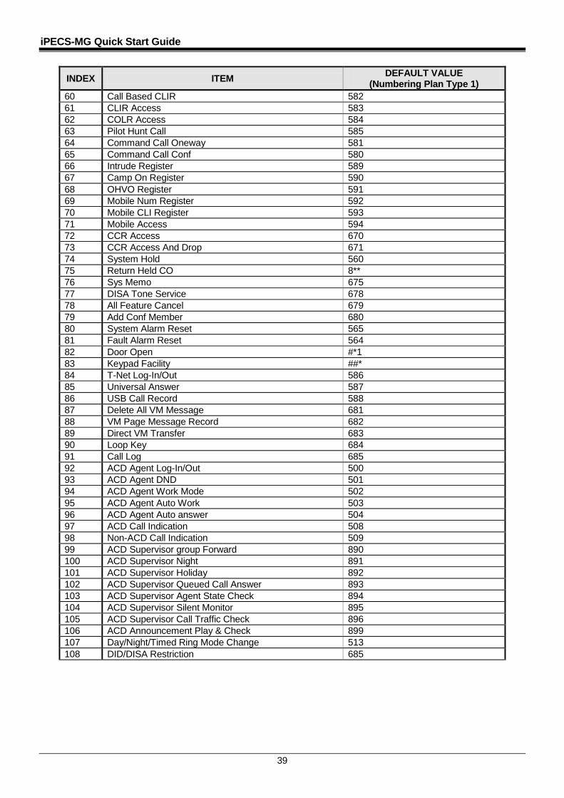
Feature Code Setting (PGM 113)
INDEX ITEM DEFAULT VALUE (Numbering Plan Type 1)
1 Attendant Call 0 2 Conference Room 1 571 3 Conference Room 2 572 4 Conference Room 3 573
iPECS-MG Quick Start Guide
38
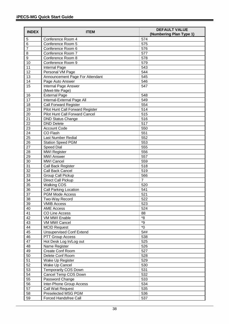
INDEX ITEM DEFAULT VALUE (Numbering Plan Type 1)
5 Conference Room 4 574 6 Conference Room 5 575 7 Conference Room 6 576 8 Conference Room 7 577 9 Conference Room 8 578 10 Conference Room 9 579 11 Internal Page 543 12 Personal VM Page 544 13 Announcement Page For Attendant 545 14 Page Auto Answer 546 15 Internal Page Answer
(Meet-Me Page) 547
16 External Page 548 17 Internal-External Page All 549 18 Call Forward Register 554 19 Pilot Hunt Call Forward Register 514 20 Pilot Hunt Call Forward Cancel 515 21 DND Status Change 516 22 DND Delete 517 23 Account Code 550 24 CO Flash 551 25 Last Number Redial 552 26 Station Speed PGM 553 27 Speed Dial 555 28 MWI Register 556 29 MWI Answer 557 30 MWI Cancel 559 31 Call Back Register 518 32 Call Back Cancel 519 33 Group Call Pickup 566 34 Direct Call Pickup 7 35 Walking COS 520 36 Call Parking Location 541 37 PGM Mode Access 521 38 Two-Way Record 522 39 VMIB Access 523 40 AME Access 524 41 CO Line Access 88 42 VM MWI Enable *8 43 VM MWI Cancel *9 44 MCID Request *0 45 Unsupervised Conf Extend 5## 46 PTT Group Access 538 47 Hot Desk Log In/Log out 525 48 Name Register 526 49 Create Conf Room 527 50 Delete Conf Room 528 51 Wake Up Register 529 52 Wake Up Cancel 530 53 Temporarily COS Down 531 54 Cancel Temp COS Down 532 55 Password Change 533 56 Inter-Phone Group Access 534 57 Call Wait Request 535 58 Preselected MSG PGM 536 59 Forced Handsfree Call 537
iPECS-MG Quick Start Guide
39
INDEX ITEM DEFAULT VALUE (Numbering Plan Type 1)
60 Call Based CLIR 582 61 CLIR Access 583 62 COLR Access 584 63 Pilot Hunt Call 585 64 Command Call Oneway 581 65 Command Call Conf 580 66 Intrude Register 589 67 Camp On Register 590 68 OHVO Register 591 69 Mobile Num Register 592 70 Mobile CLI Register 593 71 Mobile Access 594 72 CCR Access 670 73 CCR Access And Drop 671 74 System Hold 560 75 Return Held CO 8** 76 Sys Memo 675 77 DISA Tone Service 678 78 All Feature Cancel 679 79 Add Conf Member 680 80 System Alarm Reset 565 81 Fault Alarm Reset 564 82 Door Open #*1 83 Keypad Facility ##* 84 T-Net Log-In/Out 586 85 Universal Answer 587 86 USB Call Record 588 87 Delete All VM Message 681 88 VM Page Message Record 682 89 Direct VM Transfer 683 90 Loop Key 684 91 Call Log 685 92 ACD Agent Log-In/Out 500 93 ACD Agent DND 501 94 ACD Agent Work Mode 502 95 ACD Agent Auto Work 503 96 ACD Agent Auto answer 504 97 ACD Call Indication 508 98 Non-ACD Call Indication 509 99 ACD Supervisor group Forward 890 100 ACD Supervisor Night 891 101 ACD Supervisor Holiday 892 102 ACD Supervisor Queued Call Answer 893 103 ACD Supervisor Agent State Check 894 104 ACD Supervisor Silent Monitor 895 105 ACD Supervisor Call Traffic Check 896 106 ACD Announcement Play & Check 899 107 Day/Night/Timed Ring Mode Change 513 108 DID/DISA Restriction 685

iPECS-MG Quick Start Guide
40
5.2.2.6 System Time and Date Setting (PGM233) At Admin programming mode:
1. Press the [TRANS/PGM] button + 233.
2. Press the FLEX 1 Button (Time).
3. Enter 2 digits for hour and 2 digits for minutes (HHMM as 24 Hour format. For example, 1530 for 3:30 PM).
4. Press the [HOLD/SAVE] button. OR
5. Press the FLEX 2 Button (Date).
6. Enter 2 digits for month, 2 digits for day and 2 digits for year (MMDDYY, 041809 for 2009 April, 18).
7. Press the [HOLD/SAVE] button.
iPECS-MG Quick Start Guide
41
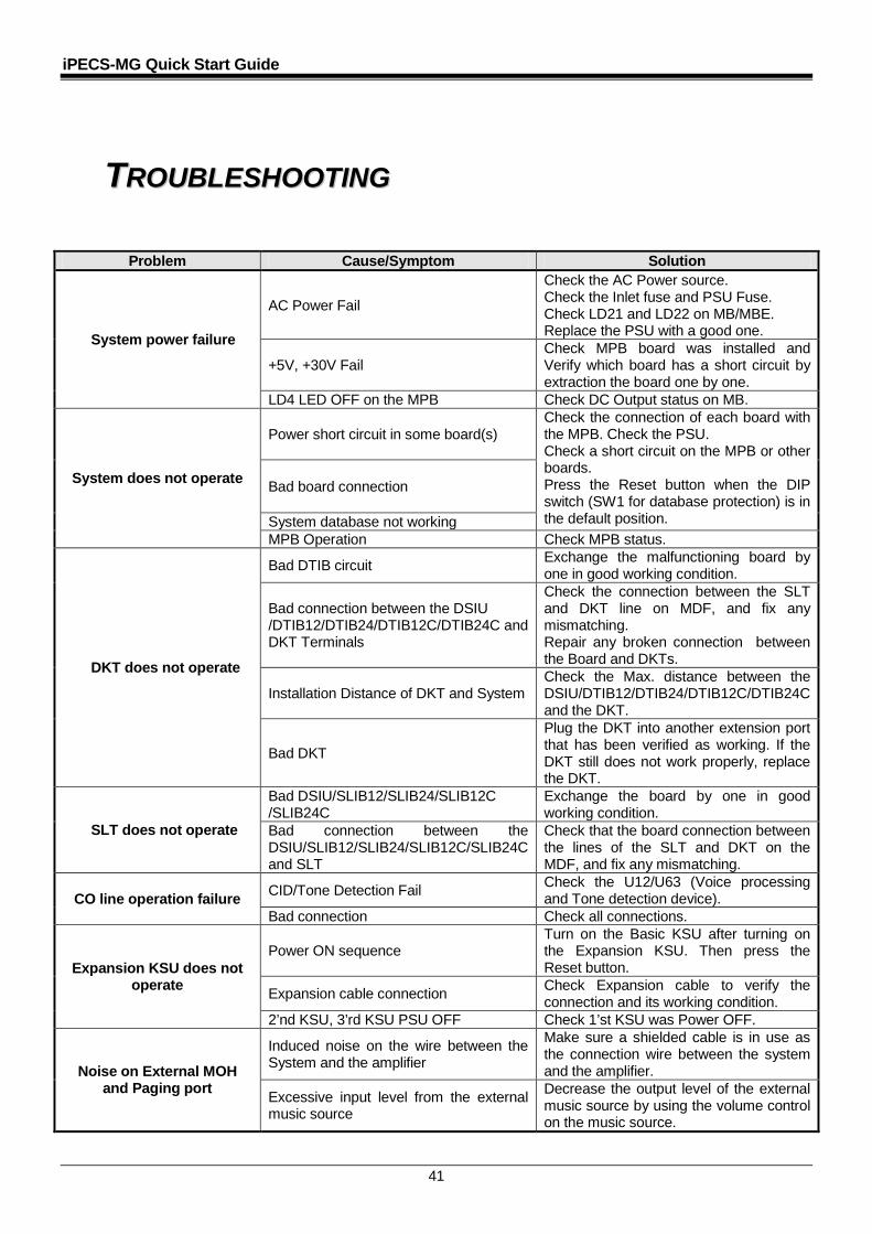
6 TTRROOUUBBLLEESSHHOOOOTTIINNGG
Problem Cause/Symptom Solution
System power failure
AC Power Fail
Check the AC Power source. Check the Inlet fuse and PSU Fuse. Check LD21 and LD22 on MB/MBE. Replace the PSU with a good one.
+5V, +30V Fail Check MPB board was installed and Verify which board has a short circuit by extraction the board one by one.
LD4 LED OFF on the MPB Check DC Output status on MB.
System does not operate
Power short circuit in some board(s) Check the connection of each board with the MPB. Check the PSU. Check a short circuit on the MPB or other boards. Press the Reset button when the DIP switch (SW1 for database protection) is in the default position.
Bad board connection
System database not working MPB Operation Check MPB status.
DKT does not operate
Bad DTIB circuit Exchange the malfunctioning board by one in good working condition.
Bad connection between the DSIU /DTIB12/DTIB24/DTIB12C/DTIB24C and DKT Terminals
Check the connection between the SLT and DKT line on MDF, and fix any mismatching. Repair any broken connection between the Board and DKTs.
Installation Distance of DKT and System Check the Max. distance between the DSIU/DTIB12/DTIB24/DTIB12C/DTIB24C and the DKT.
Bad DKT
Plug the DKT into another extension port that has been verified as working. If the DKT still does not work properly, replace the DKT.
SLT does not operate
Bad DSIU/SLIB12/SLIB24/SLIB12C /SLIB24C
Exchange the board by one in good working condition.
Bad connection between the DSIU/SLIB12/SLIB24/SLIB12C/SLIB24C and SLT
Check that the board connection between the lines of the SLT and DKT on the MDF, and fix any mismatching.
CO line operation failure CID/Tone Detection Fail Check the U12/U63 (Voice processing and Tone detection device).
Bad connection Check all connections.
Expansion KSU does not operate
Power ON sequence Turn on the Basic KSU after turning on the Expansion KSU. Then press the Reset button.
Expansion cable connection Check Expansion cable to verify the connection and its working condition.
2’nd KSU, 3’rd KSU PSU OFF Check 1’st KSU was Power OFF.
Noise on External MOH and Paging port
Induced noise on the wire between the System and the amplifier
Make sure a shielded cable is in use as the connection wire between the system and the amplifier.
Excessive input level from the external music source
Decrease the output level of the external music source by using the volume control on the music source.