Embed Size (px)
Citation preview

IP Multicast: LSM Configuration GuideFirst Published: 2012-05-16
Last Modified: 2012-11-21
Americas HeadquartersCisco Systems, Inc.170 West Tasman DriveSan Jose, CA 95134-1706USAhttp://www.cisco.comTel: 408 526-4000 800 553-NETS (6387)Fax: 408 527-0883

THE SPECIFICATIONS AND INFORMATION REGARDING THE PRODUCTS IN THIS MANUAL ARE SUBJECT TO CHANGE WITHOUT NOTICE. ALL STATEMENTS,INFORMATION, AND RECOMMENDATIONS IN THIS MANUAL ARE BELIEVED TO BE ACCURATE BUT ARE PRESENTED WITHOUT WARRANTY OF ANY KIND,EXPRESS OR IMPLIED. USERS MUST TAKE FULL RESPONSIBILITY FOR THEIR APPLICATION OF ANY PRODUCTS.
THE SOFTWARE LICENSE AND LIMITEDWARRANTY FOR THE ACCOMPANYING PRODUCT ARE SET FORTH IN THE INFORMATION PACKET THAT SHIPPED WITHTHE PRODUCT AND ARE INCORPORATED HEREIN BY THIS REFERENCE. IF YOU ARE UNABLE TO LOCATE THE SOFTWARE LICENSE OR LIMITED WARRANTY,CONTACT YOUR CISCO REPRESENTATIVE FOR A COPY.
The Cisco implementation of TCP header compression is an adaptation of a program developed by the University of California, Berkeley (UCB) as part of UCB's public domain versionof the UNIX operating system. All rights reserved. Copyright © 1981, Regents of the University of California.
NOTWITHSTANDINGANYOTHERWARRANTYHEREIN, ALL DOCUMENT FILES AND SOFTWARE OF THESE SUPPLIERS ARE PROVIDED “AS IS"WITH ALL FAULTS.CISCO AND THE ABOVE-NAMED SUPPLIERS DISCLAIM ALL WARRANTIES, EXPRESSED OR IMPLIED, INCLUDING, WITHOUT LIMITATION, THOSE OFMERCHANTABILITY, FITNESS FORA PARTICULAR PURPOSEANDNONINFRINGEMENTORARISING FROMACOURSEOFDEALING, USAGE, OR TRADE PRACTICE.
IN NO EVENT SHALL CISCO OR ITS SUPPLIERS BE LIABLE FOR ANY INDIRECT, SPECIAL, CONSEQUENTIAL, OR INCIDENTAL DAMAGES, INCLUDING, WITHOUTLIMITATION, LOST PROFITS OR LOSS OR DAMAGE TO DATA ARISING OUT OF THE USE OR INABILITY TO USE THIS MANUAL, EVEN IF CISCO OR ITS SUPPLIERSHAVE BEEN ADVISED OF THE POSSIBILITY OF SUCH DAMAGES.
Any Internet Protocol (IP) addresses and phone numbers used in this document are not intended to be actual addresses and phone numbers. Any examples, command display output, networktopology diagrams, and other figures included in the document are shown for illustrative purposes only. Any use of actual IP addresses or phone numbers in illustrative content is unintentionaland coincidental.
Cisco and the Cisco logo are trademarks or registered trademarks of Cisco and/or its affiliates in the U.S. and other countries. To view a list of Cisco trademarks, go to this URL: http://www.cisco.com/go/trademarks. Third-party trademarks mentioned are the property of their respective owners. The use of the word partner does not imply a partnershiprelationship between Cisco and any other company. (1110R)
© 2017 Cisco Systems, Inc. All rights reserved.

C O N T E N T S
C H A P T E R 1 Read Me First 1
C H A P T E R 2 MLDP-Based MVPN 3
Finding Feature Information 3
Information About MLDP-Based MVPN 3
Overview of MLDP-Based MVPN 3
Benefits of MLDP-Based MVPN 6
Initial Deployment of an MLDP-Based MVPN 6
Default MDT Creation 6
LSP Downstream Default MDT Creation 7
LSP Upstream Default MDT Creation 9
PIM Overlay Signaling of VPN Multicast State 11
Data MDT Scenario 12
How to Configure MLDP-Based MVPN 13
Configuring Initial MLDP Settings 13
Configuring an MLDP-Based MVPN 14
Verifying the Configuration of an MLDP-Based MVPN 17
Configuration Examples for MLDP-Based MVPN 19
Example Initial Deployment of an MLDP-Based MVPN 19
Default MDT Configuration 20
PIM Adjacencies 21
MLDP Database Entry--PE-East 21
Label Forwarding Entry--P-Central (Root 1) 22
Data MDT Configuration 24
VRF mroute Table--PE-West 25
LSP-VIF Adjacencies--PE-West 25
MLDP Database Entries 26
LFIB Entry for the Data MDT 27
IP Multicast: LSM Configuration Guide iii

Example Migration from a PIM with mGRE-Based MVPN to an MLDP-Based MPVN 27
Additional References 28
Feature Information for MLDP-Based MVPN 28
C H A P T E R 3 IPv6 Multicast Listener Discovery Protocol 31
Finding Feature Information 31
Information About IPv6 Multicast Listener Discovery Protocol 31
IPv6 Multicast Overview 31
IPv6 Multicast Routing Implementation 32
Multicast Listener Discovery Protocol for IPv6 33
MLD Access Group 34
How to Configure IPv6 Multicast Listener Discovery Protocol 34
Enabling IPv6 Multicast Routing 34
Customizing and Verifying MLD on an Interface 35
Disabling MLD Device-Side Processing 37
Resetting the MLD Traffic Counters 38
Clearing the MLD Interface Counters 39
Configuration Examples for IPv6 Multicast Listener Discovery Protocol 40
Example: Enabling IPv6 Multicast Routing 40
Example: Configuring the MLD Protocol 40
Example: Disabling MLD Router-Side Processing 41
Additional References 41
IPv6 Multicast Listener Discovery Protocol 42
C H A P T E R 4 MLD Group Limits 45
Finding Feature Information 45
Information About MLD Group Limits 45
Multicast Listener Discovery Protocol for IPv6 45
How to Implement MLD Group Limits 47
Implementing MLD Group Limits Globally 47
Implementing MLD Group Limits per Interface 47
Configuration Examples for MLD Group Limits 48
Example: Implementing MLD Group Limits 48
Additional References 49
Feature Information for MLD Group Limits 50
IP Multicast: LSM Configuration Guideiv
Contents

C H A P T E R 5 MLDP In-Band Signaling/Transit Mode 51
Finding Feature Information 51
Restrictions for MLDP In-Band Signaling 51
Information About MLDP In-Band Signaling/Transit Mode 52
MLDP In-Band Signaling/Transit Mode 52
How to Configure MLDP In-Band Signaling/Transit Mode 52
Enabling In-Band Signaling on a PE Device 52
Additional References 53
Configuration Examples for MLDP In-Band Signaling/Transit Mode 54
Example: In-Band Signaling on PE1 54
Example: In-Band Signaling on PE2 57
Feature Information for MLDP In-Band Signaling/Transit Mode 60
C H A P T E R 6 HA Support for MLDP 63
Finding Feature Information 63
Prerequisites for HA Support for MLDP 63
Restrictions for HA Support for MLDP 64
Information About HA Support for MLDP 64
How to Montior HA Support for MLDP 64
Displaying Check Pointed Information 64
Displaying Data MDT Mappings for MLDP on Standby Device 65
Additional References 66
Feature Information for HA Support for MLDP 67
IP Multicast: LSM Configuration Guide v
Contents

IP Multicast: LSM Configuration Guidevi
Contents

C H A P T E R 1Read Me First
Important Information about Cisco IOS XE 16
Effective Cisco IOS XE Release 3.7.0E (for Catalyst Switching) and Cisco IOS XE Release 3.17S (forAccess and Edge Routing) the two releases evolve (merge) into a single version of converged release—theCisco IOS XE 16—providing one release covering the extensive range of access and edge products in theSwitching and Routing portfolio.
Feature Information
Use Cisco Feature Navigator to find information about feature support, platform support, and Cisco softwareimage support. An account on Cisco.com is not required.
Related References
• Cisco IOS Command References, All Releases
Obtaining Documentation and Submitting a Service Request
For information on obtaining documentation, using the Cisco Bug Search Tool (BST), submitting a servicerequest, and gathering additional information, see What's New in Cisco Product Documentation.
To receive new and revised Cisco technical content directly to your desktop, you can subscribe to the What'sNew in Cisco Product Documentation RSS feed. RSS feeds are a free service.
IP Multicast: LSM Configuration Guide 1

IP Multicast: LSM Configuration Guide2
Read Me First

C H A P T E R 2MLDP-Based MVPN
The MLDP-based MVPN feature provides extensions to Label Distribution Protocol (LDP) for the setup ofpoint-to-multipoint (P2MP) andmultipoint-to-multipoint (MP2MP) label switched paths (LSPs) for transportin the Multicast Virtual Private Network (MVPN) core network.
• Finding Feature Information, page 3
• Information About MLDP-Based MVPN, page 3
• How to Configure MLDP-Based MVPN, page 13
• Configuration Examples for MLDP-Based MVPN, page 19
• Additional References, page 28
• Feature Information for MLDP-Based MVPN, page 28
Finding Feature InformationYour software release may not support all the features documented in this module. For the latest caveats andfeature information, see Bug Search Tool and the release notes for your platform and software release. Tofind information about the features documented in this module, and to see a list of the releases in which eachfeature is supported, see the feature information table.
Use Cisco Feature Navigator to find information about platform support and Cisco software image support.To access Cisco Feature Navigator, go to www.cisco.com/go/cfn. An account on Cisco.com is not required.
Information About MLDP-Based MVPN
Overview of MLDP-Based MVPNMVPN allows a service provider to configure and support multicast traffic in an MPLS VPN environment.This feature supports routing and forwarding of multicast packets for each individual VPN routing andforwarding (VRF) instance, and it also provides a mechanism to transport VPN multicast packets across theservice provider backbone.
IP Multicast: LSM Configuration Guide 3

A VPN is network connectivity across a shared infrastructure, such as an Internet service provider (ISP). Itsfunction is to provide the same policies and performance as a private network, at a reduced cost of ownership,thus creating many opportunities for cost savings through operations and infrastructure.
AnMVPN allows an enterprise to transparently interconnect its private network across the network backboneof a service provider. The use of an MVPN to interconnect an enterprise network in this way does not changethe way that the enterprise network is administered, nor does it change general enterprise connectivity.
As shown in the figure, in an MLDP-based MVPN, a static default multicast distribution tree (MDT) isestablished for each multicast domain. The default MDT defines the path used by provider edge (PE) devicesto send multicast data and control messages to every other PE device in the multicast domain. A default MDTis created in the core network using a single MP2MP LSP. The default MDT behaves like a virtual LAN.
Figure 1: MLDP with the Default MDT Scenario
As shown in the figure, an MLDP-based MVPN also supports the dynamic creation of data MDTs forhigh-bandwidth transmission. For high-rate data sources, a data MDT is created using P2MP LSPs to off-loadtraffic from the default MDT to avoid unnecessary waste of bandwidth to PEs that did not join the stream.The creation of the data MDT is signaled dynamically using MDT Join TLV messages. Data MDTs are afeature unique to Cisco IOS software. DataMDTs are intended for high-bandwidth sources such as full-motionvideo inside the VPN to ensure optimal traffic forwarding in the MPLS VPN core. The threshold at whichthe dataMDT is created can be configured on a per-device or a per-VRF basis.When the multicast transmission
IP Multicast: LSM Configuration Guide4
MLDP-Based MVPNOverview of MLDP-Based MVPN

exceeds the defined threshold, the sending PE device creates the dataMDT and sends a User Datagram Protocol(UDP) message, which contains information about the data MDT to all devices on the default MDT.
Figure 2: MLDP with the Data MDT Scenario
Data MDTs are created only for (S, G) multicast route entries within the VRF multicast routing table. Theyare not created for (*, G) entries regardless of the value of the individual source data rate.
The only transport mechanism previously available was Protocol IndependentMulticast (PIM) withMultipointGeneric Routing Encapsulation (mGRE) over an IP core network. The introduction of Multicast LabelDistribution Protocol (MLDP) provides transport by using MLDP with label encapsulation over an MPLScore network.
MLDP creates the MDTs as follows:
• The default MDT uses MP2MP LSPs.
• Supports low bandwidth and control traffic between VRFs.
• The data MDT uses P2MP LSPs.
• Supports a single high-bandwidth source stream from a VRF.
All other operations of MVPN remain the same regardless of the tunneling mechanism:
• PIM neighbors in a VRF are seen across a Label Switched Path virtual interface (LSP-VIF).
• The VPN multicast state is signaled by PIM.
The only other difference when using MLDP is that the MDT group address used in the mGRE solution isreplaced with a VPN ID.
IP Multicast: LSM Configuration Guide 5
MLDP-Based MVPNOverview of MLDP-Based MVPN

Benefits of MLDP-Based MVPN• Enables the use of a single MPLS forwarding plane for both unicast and multicast traffic.
• Enables existing MPLS protection (for example, MPLS Traffic Engineering/Resource ReservationProtocol (TE/RSVP link protection) and MPLS Operations Administration and Maintenance (OAM)mechanisms to be used for multicast traffic.
• Reduces operational complexity due to the elimination of the need for PIM in the MPLS core network.
Initial Deployment of an MLDP-Based MVPNInitial deployment of an MLDP-based MVPN involves the configuration of a default MDT and one or moredata MDTs.
A static default MDT is established for each multicast domain. The default MDT defines the path used by PEdevices to send multicast data and control messages to every other PE device in the multicast domain. Adefault MDT is created in the core network using a single MP2MP LSP.
An MLDP-based MVPN also supports the dynamic creation of data MDTs for high-bandwidth transmission.
Default MDT CreationThe figure shows the default MDT scenario. The Opaque value used to signal a default MDT consists of twoparameters: the VPN ID and theMDT number for the VPN in the format (vpn-id, 0) where vpn-id is a manuallyconfigured 7-byte number that uniquely identifies this VPN. The default MDT is set to zero.
In this scenario, each of the three PE devices belong to the VRF called VRF and they have the same VPN ID.Each PE device with the sameVPN IDwill join the sameMP2MP tree. The PE devices have created a primaryMP2MP tree rooted at P-Central (Root 1) and a backup MP2MP tree rooted at PE-North (Root 2). There aretwo sources at PE-West and interested receivers at both PE-North and PE-East. PE-West will choose one of
IP Multicast: LSM Configuration Guide6
MLDP-Based MVPNBenefits of MLDP-Based MVPN

the MP2MP trees to transmit the customer VPN traffic, but all PE devices can receive traffic on either of theMP2MP trees.
Figure 3: Default MDT Scenario
LSP Downstream Default MDT Creation
The figures show the downstream tree creation for each of the roots. Each PE device configured with VPNID 100:2 creates the same Forwarding Equivalence Class (FEC) Type Length Value (TLV), but with a differentroot and downstream labels per MP2MP tree. The FEC type will be MP2MP Down, which prompts the
IP Multicast: LSM Configuration Guide 7
MLDP-Based MVPNInitial Deployment of an MLDP-Based MVPN

receiving Label Switched Route (LSR) to respond with an upstream label mapping message to create theupstream path.
Figure 4: Default MDT Downstream--Root 1
Figure 5: Default MDT Downstream--Root 2
IP Multicast: LSM Configuration Guide8
MLDP-Based MVPNInitial Deployment of an MLDP-Based MVPN

LSP Upstream Default MDT Creation
The figures show the upstream LSP creation for the default MDTs. For each downstream label received, acorresponding upstream label is sent. In the first figure, P-Central sends out three upstream labels (111, 109,and 105) to each downstream directly connected neighbor (downstream is away from the root). The process
IP Multicast: LSM Configuration Guide 9
MLDP-Based MVPNInitial Deployment of an MLDP-Based MVPN

for PE-North is the same except that it only sends a single upstream label (313) as there is only one directlyconnected downstream neighbor, as shown in the second figure.
Figure 6: Default MDT Upstream--Root 1
Figure 7: Default MDT Upstream--Root 2
IP Multicast: LSM Configuration Guide10
MLDP-Based MVPNInitial Deployment of an MLDP-Based MVPN

PIM Overlay Signaling of VPN Multicast State
The signaling of the multicast state within a VPN is via PIM. It is called overlay signaling because the PIMsession runs over the multipoint LSP and maps the VPNmulticast flow to the LSP. In anMVPN, the operationof PIM is independent of the underlying tunnel technology. In theMVPN solution, a PIM adjacency is createdbetween PE devices, and the multicast states within a VRF are populated over the PIM sessions. When usingMLDP, the PIM session runs over an LSP-VIF interface. The figure shows PIM signaling running over thedefault MDT MP2MP LSP. Access to the MP2MP LSP is via the LSP-VIF, which can see all the leaf PEdevices at the end of branches, much like a LAN interface. In the figure, PE-East sends a downstream labelmapping message to the root, P-Central, which in turn sends an upstream label mapping message to PE-West.These messages result in the creation of the LSP between the two leaf PE devices. A PIM session can thenbe activated over the top of the LSP allowing the (S, G) states and control messages to be signaled betweenPE-West and PE-East. In this case, PE-East receives a Join TLVmessage for (10.5.200.3, 238.1.200.2) withinVRF, which it inserts into the mroute table. The Join TLVmessage is then sent via the PIM session to PE-West
IP Multicast: LSM Configuration Guide 11
MLDP-Based MVPNInitial Deployment of an MLDP-Based MVPN
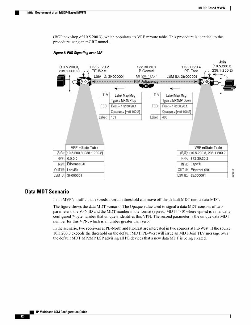
(BGP next-hop of 10.5.200.3), which populates its VRF mroute table. This procedure is identical to theprocedure using an mGRE tunnel.
Figure 8: PIM Signaling over LSP
Data MDT ScenarioIn an MVPN, traffic that exceeds a certain threshold can move off the default MDT onto a data MDT.
The figure shows the data MDT scenario. The Opaque value used to signal a data MDT consists of twoparameters: the VPN ID and the MDT number in the format (vpn-id, MDT# > 0) where vpn-id is a manuallyconfigured 7-byte number that uniquely identifies this VPN. The second parameter is the unique data MDTnumber for this VPN, which is a number greater than zero.
In the scenario, two receivers at PE-North and PE-East are interested in two sources at PE-West. If the source10.5.200.3 exceeds the threshold on the default MDT, PE-West will issue an MDT Join TLV message overthe default MDT MP2MP LSP advising all PE devices that a new data MDT is being created.
IP Multicast: LSM Configuration Guide12
MLDP-Based MVPNInitial Deployment of an MLDP-Based MVPN

Because PE-East has an interested receiver in VRF, it will build a multipoint LSP using P2MP back to PE-West,which will be the root of the tree. PE-North does not have a receiver for 10.5.200.3, therefore it will just cachethe Join TLV message.
Figure 9: Data MDT Scenario
How to Configure MLDP-Based MVPN
Configuring Initial MLDP SettingsPerform this task to configure the initial MLDP settings.
IP Multicast: LSM Configuration Guide 13
MLDP-Based MVPNHow to Configure MLDP-Based MVPN

SUMMARY STEPS
1. enable2. configure terminal3. mpls mldp logging notifications4. mpls mldp forwarding recursive5. end
DETAILED STEPS
PurposeCommand or Action
Enables privileged EXEC mode.enableStep 1
Example:
Device> enable
• Enter your password if prompted.
Enters global configuration mode.configure terminal
Example:
Device# configure terminal
Step 2
Enables MLDP logging notifications.mpls mldp logging notifications
Example:
Device(config)# mpls mldp logging notifications
Step 3
EnablesMLDP recursive forwarding over a P2MPLSP.mpls mldp forwarding recursive
Example:
Device(config)# mpls mldp forwarding recursive
Step 4
Ends the current configuration session and returns toprivileged EXEC mode.
end
Example:
Device(config)# end
Step 5
Configuring an MLDP-Based MVPNPerform this task to configure an MLDP-based MVPN.
IP Multicast: LSM Configuration Guide14
MLDP-Based MVPNConfiguring an MLDP-Based MVPN

SUMMARY STEPS
1. enable2. configure terminal3. ip multicast-routing4. ip multicast-routing vrf vrf-name5. ip vrf vrf-name6. rd route-distinguisher7. vpn id oui : vpn-index8. route target export route-target-ext-community9. route target import route-target-ext-community10. mdt preference { mldp | pim }11. mdt default mpls mldp group-address12. mdt data mpls mldp number-of-data-mdt13. mdt data threshold kb/s list access-list14. end
DETAILED STEPS
PurposeCommand or Action
Enables privileged EXEC mode.enableStep 1
Example:
Device> enable
• Enter your password if prompted.
Enters global configuration mode.configure terminal
Example:
Device# configure terminal
Step 2
Enables IP multicast routing.ip multicast-routing
Example:
Device(config)# ip multicast-routing
Step 3
Enables IPmulticast routing for theMVPNVRF specifiedfor the vrf-name argument.
ip multicast-routing vrf vrf-name
Example:
Device(config)# ip multicast-routing vrf VRF
Step 4
IP Multicast: LSM Configuration Guide 15
MLDP-Based MVPNConfiguring an MLDP-Based MVPN

PurposeCommand or Action
Defines a VRF instance and enters VRF configurationmode.
ip vrf vrf-name
Example:
Device(config-vrf)# ip vrf VRF
Step 5
Creates a route distinguisher (RD) (in order to make theVRF functional). Creates the routing and forwarding
rd route-distinguisher
Example:
Device(config-vrf)# rd 50:11
Step 6
tables, associates the RD with the VRF instance, andspecifies the default RD for a VPN.
Sets or updates the VPN ID on a VRF instance.vpn id oui : vpn-index
Example:
Device(config-vrf)# vpn id 50:10
Step 7
Creates an export route target extended community forthe specified VRF.
route target export route-target-ext-community
Example:
Device(config-vrf)# route target export 100:100
Step 8
Creates an import route target extended community forthe specified VRF.
route target import route-target-ext-community
Example:
Device(config-vrf)# route target import 100:100
Step 9
Specifies a preference for a particular MDT type (MLDPor PIM).
mdt preference { mldp | pim }
Example:
Device(config-vrf)# mdt preference mldp
Step 10
Configures a default MDT group for a VPN VRFinstance.
mdt default mpls mldp group-address
Example:
Device(config-vrf)# mdt default mpls mldp172.30.20.1
Step 11
Specifies a range of addresses to be used in the dataMDTpool.
mdt data mpls mldp number-of-data-mdt
Example:
Device(config-vrf)# mdt data mpls mldp 255
Step 12
IP Multicast: LSM Configuration Guide16
MLDP-Based MVPNConfiguring an MLDP-Based MVPN

PurposeCommand or Action
Defines the bandwidth threshold value in kilobits persecond.
mdt data threshold kb/s list access-list
Example:
Device(config-vrf)# mdt data threshold 40 list1
Step 13
Ends the current configuration session and returns toprivileged EXEC mode.
end
Example:
Device(config)# end
Step 14
Verifying the Configuration of an MLDP-Based MVPNPerform this task in privileged EXEC mode to verify the configuration of an MLDP-based MVPN.
SUMMARY STEPS
1. show mpls mldp database2. show ip pim neighbor [vrf vrf-name] neighbor [interface-type interface-number]3. show ip mroute [vrf vrf-name] [[active [kbps] [interface type number] | bidirectional | count [terse] |
dense | interface type number | proxy | pruned | sparse | ssm | static | summary] | [group-address[source-address]] [count [terse] | interface type number | proxy | pruned | summary] | [source-addressgroup-address] [count [terse] | interface type number | proxy | pruned | summary] | [group-address]active [kbps] [interface type number | verbose]]
4. show mpls forwarding-table [network {mask | length} | labels label [- label] | interface interface |next-hop address | lsp-tunnel [tunnel-id]] [vrf vrf-name] [detail]
5. show adjacency [ip-address] [interface-type interface-number | null number | port-channel number |sysclock number | vlan number | fcpa number | serial number] [connectionid number] [link {ipv4 |mpls}][detail | encapsulation]
DETAILED STEPS
Step 1 show mpls mldp databaseEnter the show mpls mldp databasecommand to display information in the MLDP database. It shows the FEC, theOpaque value of the FEC decoded, and the replication clients associated with it:
Example:
Device# show mpls mldp database* Indicates MLDP recursive forwarding is enabledLSM ID : D3000001 (RNR LSM ID: 8A000002) Type: MP2MP Uptime : 00:04:54FEC Root : 172.30.20.1
IP Multicast: LSM Configuration Guide 17
MLDP-Based MVPNVerifying the Configuration of an MLDP-Based MVPN

Opaque decoded : [mdt 100:2 0]Opaque length : 11 bytesOpaque value : 07 000B 0000010000000100000000RNR active LSP : (this entry)Upstream client(s) :172.30.20.1:0 [Active]Expires : Never Path Set ID : 99000001Out Label (U) : 32 Interface : Ethernet1/0*Local Label (D): 30 Next Hop : 10.0.1.7
Replication client(s):MDT (VRF VRF)Uptime : 00:04:54 Path Set ID : 5000002Interface : Lspvif0
Step 2 show ip pim neighbor [vrf vrf-name] neighbor [interface-type interface-number]Enter the show ip pim neighborcommand to display PIM adjacencies information:
Example:
Device# show ip pim vrf VRF neighbor192.168.10.18 Serial6/0 04:53:19/00:01:18 v2 1 / G172.30.20.3 Lspvif0 04:52:32/00:01:28 v2 1 / B S P G172.30.20.2 Lspvif0 04:52:32/00:01:17 v2 1 / B S P G
Step 3 show ipmroute [vrf vrf-name] [[active [kbps] [interface type number] | bidirectional | count [terse] | dense | interfacetype number | proxy | pruned | sparse | ssm | static | summary] | [group-address [source-address]] [count [terse] |interface type number | proxy | pruned | summary] | [source-address group-address] [count [terse] | interface typenumber | proxy | pruned | summary] | [group-address] active [kbps] [interface type number | verbose]]Enter the show ip mroutecommand to display the contents of the multicast routing (mroute) table:
Example:
Device# show ip mroute vrf VRF 238.1.200.2 10.5.200.3(10.5.200.3, 238.1.200.2), 04:54:18/00:02:40, flags: sTIncoming interface: Lspvif0, RPF nbr 172.30.20.2Outgoing interface list:Serial6/0, Forward/Sparse-Dense, 04:54:18/00:02:40
Step 4 show mpls forwarding-table [network {mask | length} | labels label [- label] | interface interface | next-hop address| lsp-tunnel [tunnel-id]] [vrf vrf-name] [detail]Enter the show mpls forwarding-tablecommand to display the contents of the MPLS Label Forwarding InformationBase (LFIB):
Example:
Device# show mpls forwarding-table | inc 1F000001105 307 mLDP:1F000001 38468 Se5/0 point2point
208 mLDP:1F000001 38468 Se4/0 point2point109 307 mLDP:1F000001 34738 Se5/0 point2point
408 mLDP:1F000001 34738 Se6/0 point2point111 408 mLDP:1F000001 282 Se6/0 point2point
208 mLDP:1F000001 282 Se4/0 point2point
Step 5 show adjacency [ip-address] [interface-type interface-number | null number | port-channel number | sysclock number| vlan number | fcpa number | serial number] [connectionid number] [link {ipv4 |mpls}] [detail | encapsulation]Enter the show adjacencycommand to display adjacency information for the specified LSP-VIF interface:
IP Multicast: LSM Configuration Guide18
MLDP-Based MVPNVerifying the Configuration of an MLDP-Based MVPN

Example:
Device# show adjacency lspvif0105 307 mLDP:1F000001 38468 Se5/0 point2point
208 mLDP:1F000001 38468 Se4/0 point2point109 307 mLDP:1F000001 34738 Se5/0 point2point
408 mLDP:1F000001 34738 Se6/0 point2point111 408 mLDP:1F000001 282 Se6/0 point2point
208 mLDP:1F000001 282 Se4/0 point2point
Configuration Examples for MLDP-Based MVPN
Example Initial Deployment of an MLDP-Based MVPNInitial deployment of an MLDP-based MVPN involves the configuration of a default MDT and one or moredata MDTs.
IP Multicast: LSM Configuration Guide 19
MLDP-Based MVPNConfiguration Examples for MLDP-Based MVPN

Default MDT ConfigurationThe following example shows how to configure the default MDT for an MLDP-based MVPN. Thisconfiguration is based on the sample topology illustrated in the figure.
Figure 10: Default MDT Example
This configuration is consistent for every PE device participating in the same VPN ID. The vpn id 100:2command replaces the MDT group address used with the mGRE transport method. To provide redundancy,two default MDT trees are statically configured, rooted at P-Central and PE-North. The selection as to whichMP2MP tree the default MDT will use at a particular PE device is determined by Interior Gateway Protocol(IGP) metrics. An MP2MP LSP is implicit for the default MDT.
ip pim mpls source Loopback0ip multicast-routingip multicast-routing vrf VRF!ip vrf VRFrd 100:2vpn id 100:2route-target export 200:2route-target import 200:2
IP Multicast: LSM Configuration Guide20
MLDP-Based MVPNExample Initial Deployment of an MLDP-Based MVPN

mdt default mpls mldp 172.30.20.1 (P-Central)mdt default mpls mldp 172.30.20.3 (PE-North)
PIM Adjacencies
PIM operates over the LSP-VIF as if it were a regular tunnel interface. That means PIM hellos are exchangedover the LSP-VIF to establish PIM adjacencies over the default MDT. The sample output in this sectiondisplays the three PIM adjacencies in VRF of PE-East. The first is the adjacency to the receiver network overserial interface 6/0, and the next two are the adjacencies to PE-West and PE-North over the MP2MP LSP viaLSP-VIF interface 0.
PE-East# show ip pim vrf VRF neighbor192.168.10.18 Serial6/0 04:53:19/00:01:18 v2 1 / G172.30.20.3 Lspvif0 04:52:32/00:01:28 v2 1 / B S P G172.30.20.2 Lspvif0 04:52:32/00:01:17 v2 1 / B S P GThe output from the show ip mroute command also shows the (S, G) entry for VRF. The stream 238.1.200.2has the Reverse Path Forwarding (RPF) interface of LSP-VIF interface 0 and the neighbor 172.30.20.2, whichis PE-West.
PE-East# show ip mroute vrf VRF 238.1.200.2 10.5.200.3(10.5.200.3, 238.1.200.2), 04:54:18/00:02:40, flags: sTIncoming interface: Lspvif0, RPF nbr 172.30.20.2Outgoing interface list:Serial6/0, Forward/Sparse-Dense, 04:54:18/00:02:40
MLDP Database Entry--PE-East
The sample output in this section displays the database entries for the MP2MP trees supporting the defaultMDT at PE-East. The database is searched by Opaque value MDT 100:2, which results in information fortwo MP2MP trees (one for each root) being returned. Both trees have different system IDs (2E000001,F2000005) and use the same Opaque value ([mdt 100:2 0]), but with different roots. The last 0 in the Opaquevalue indicates this tree is a default MDT. Entry 79000004 shows it is the primary MP2MP tree, thereforePE-East will transmit all source multicast traffic on this LSP, and B2000006 will be the backup root. Notethat interface LSP-VIF interface 0 represents both MP2MP LSPs. The Local Label (D) is the downstreamlabel allocated by PE-East for this tree. In other words, traffic from the root will be received with either label408 (Primary Tree) or 407 (Backup Tree). The Out Label (U) is the label that PE-East will use to send trafficinto the tree; upstream towards the root, either 105 for the Primary Tree or 108 for the Backup Tree. Boththese labels were received from P-Central.
PE-East# show mpls mldp database opaque_type mdt 100:2* Indicates MLDP recursive forwarding is enabledLSM ID : 79000004 (RNR LSM ID: 8A000002) Type: MP2MP Uptime : 00:04:54FEC Root : 172.30.20.1Opaque decoded : [mdt 100:2 0]Opaque length : 11 bytesOpaque value : 07 000B 0000010000000100000000RNR active LSP : (this entry)Upstream client(s) :172.30.20.1:0 [Active]Expires : Never Path Set ID : 99000001Out Label (U) : 32 Interface : Ethernet1/0*Local Label (D): 30 Next Hop : 10.0.1.7
Replication client(s):MDT (VRF VRF)Uptime : 00:04:54 Path Set ID : 5000002Interface : Lspvif0
LSM ID : 79000005 (RNR LSM ID: 8A000003) Type: MP2MP Uptime : 00:04:54FEC Root : 172.30.20.3Opaque decoded : [mdt 100:2 0]Opaque length : 11 bytes
IP Multicast: LSM Configuration Guide 21
MLDP-Based MVPNExample Initial Deployment of an MLDP-Based MVPN

Opaque value : 07 000B 0000010000000100000001RNR active LSP : (this entry)Upstream client(s) :172.30.20.1:0 [Active]Expires : Never Path Set ID : 99000002Out Label (U) : 32 Interface : Ethernet1/0*Local Label (D): 30 Next Hop : 10.0.1.7
Replication client(s):MDT (VRF VRF)Uptime : 00:04:54 Path Set ID : 5000003Interface : Lspvif0
Label Forwarding Entry--P-Central (Root 1)
The sample output shown in this section displays the VRF (MDT 100:2) MLDP database entry 1F000001 forthe primary MP2MP LSP, which is P-Central. Because the local device P-Central is the root, there is noupstream peer ID, therefore no labels are allocated locally. However there are three replication clients,representing each of the three PE devices: PE-North, PE-West, and PE-East. These replication clients are thedownstream nodes of the MP2MP LSP. These clients receive multipoint replicated traffic.
In the replication entry looking from the perspective of the root, there are two types of labels:
• Out label (D)--These are labels received from remote peers that are downstream to the root (remembertraffic flows downstream away from the root).
• Local label (U)--These are labels provided by P-Central to its neighbors to be used as upstream labels(sending traffic to the root). It is easy to identify these labels as they all start in the 100 range, which wehave configured for P-Central to use. P-Central sends these labels out when it receives a FEC with thetype as MP2MP Down.
From the labels received and sent in the replication entries, the Label Forwarding Information Base (LFIB)is created. The LFIB has one entry per upstream path and one entry per downstream path. In this case becauseP-Central is the root, there are only upstream entries in the LFIB that have been merged with the correspondingdownstream labels. For example, label 105 is the label P-Central sent to PE-East to send source traffic upstream.Traffic received from PE-East will then be replicated using the downstream labels 307 to PE-West and 208to PE-North.
P-Central# show mpls mldp database opaque_type mdt 100:2LSM ID : 79000006 (RNR LSM ID: 1F000001) Type: MP2MP Uptime : 00:04:54FEC Root : 172.30.20.1Opaque decoded : [mdt 100:2 0]Opaque length : 11 bytesOpaque value : 07 000B 0000010000000100000000RNR active LSP : (this entry)Upstream client(s) : NoneReplication client(s):172.3.20.2:0Uptime : 01:46:43 Path Set ID : AC000008Out label (D) : 208 Interface : Serial4/0Local label (U): 109 Next Hop : 172.30.10.2
172.3.20.3:0Uptime : 01:42:43 Path Set ID : E00000COut label (D) : 307 Interface : Serial5/0Local label (U): 111 Next Hop : 172.30.10.6
172.3.20.4:0Uptime : 01:40:43 Path Set ID : 3D000010Out label (D) : 408 Interface : Serial6/0Local label (U): 105 Next Hop : 172.30.10.10
P-Central# show mpls forwarding-table | inc 1F000001105 307 mLDP:1F000001 38468 Se5/0 point2point
208 mLDP:1F000001 38468 Se4/0 point2point109 307 mLDP:1F000001 34738 Se5/0 point2point
408 mLDP:1F000001 34738 Se6/0 point2point
IP Multicast: LSM Configuration Guide22
MLDP-Based MVPNExample Initial Deployment of an MLDP-Based MVPN

111 408 mLDP:1F000001 282 Se6/0 point2point208 mLDP:1F000001 282 Se4/0 point2point
The sample output shown in this section displays the entry on P-Central for theMP2MPLSP rooted at PE-North(backup root). In this tree P-Central is a branch of the tree, not a root, therefore there are someminor differencesto note:
• The upstream peer ID is PE-North, therefore P-Central has allocated label 104 in the downstream directiontowards PE-North and subsequently PE-North has responded with an upstream label of 313.
• Two replication entries representing PE-East and PE-West are displayed.
• The merged LFIB shows three entries:
• One downstream entry label 104 receiving traffic from Root 2 (PE-North), which is then directedfurther downstream using labels 207 PE-West and 407 PE-East.
• Two upstream entries 108 and 115 receiving traffic from the leaves and directing it eitherdownstream 207, 407 or upstream using label 313.
Central_P# show mpls mldp database opaque_type mdt 100:2LSM ID : E6000004Uptime : 00:42:03Tree type : MP2MPFEC Root : 172.30.20.3Opaque length : 14 bytesOpaque value : 07000B00 01000000 00020000 00009COpaque decoded : [mdt 100:2 0]Upstream peer ID : 172.30.20.3:0, Label local (D): 104 remote (U): 313 activePath Set ID : 48000003Replication client(s):172.30.20.2:0 uptime: 00:42:03 Path Set ID: CF000004
remote label (D): 207 local label (U): 115nhop: 172.30.10.2 intrf: Serial4/0
172.30.20.4:0 uptime: 00:41:44 Path Set ID: 5800000Eremote label (D): 407 local label (U): 108nhop: 172.30.10.10 intrf: Serial6/0
Central_P# show mpls forwarding-table | inc E6000004104 207 mLDP:E6000004 251228 Se4/0 point2point
407 mLDP:E6000004 251334 Se6/0 point2point108 207 mLDP:E6000004 0 Se4/0 point2point
313 mLDP:E6000004 0 Se5/0 point2point115 313 mLDP:E6000004 0 Se5/0 point2point
407 mLDP:E6000004 0 Se6/0 point2point
IP Multicast: LSM Configuration Guide 23
MLDP-Based MVPNExample Initial Deployment of an MLDP-Based MVPN

Data MDT ConfigurationThe following example shows how to configure the dataMDT for anMLDP-basedMVPN. This configurationis based on the sample topology illustrated in the figure.
Figure 11: Data MDT Example
The sample output in this section displays the data MDT configuration for all the PE devices. Themdt datacommands are the only additional commands necessary. The firstmdt datacommand allows a maximum of60 data MDTs to be created, and the secondmdt datacommand sets the threshold. If the number of dataMDTs exceeds 60, then the data MDTs will be reused in the same way as they are for the mGRE tunnelmethod (the one with the lowest reference count).
ip pim vrf VRF mpls source Loopback0!ip vrf VRFrd 100:2vpn id 100:2route-target export 200:2route-target import 200:2mdt default mpls mldp 172.30.20.1 (P-Central)mdt default mpls mldp 172.30.20.3 (PE-North)
IP Multicast: LSM Configuration Guide24
MLDP-Based MVPNExample Initial Deployment of an MLDP-Based MVPN

mdt data mpls mldp 60mdt data threshold 1
VRF mroute Table--PE-West
The sample output in this section displays the VRFmroute table on PE-West before the high-bandwidth sourceexceeds the threshold. At this point there are two streams, representing each of the two VPN sources atPE-West, on a single MP2MP LSP (System ID D8000000). The LSP represents the default MDT accessedvia LSP-VIF interface 0.
PE-West# show ip mroute vrf VRF verbose...(10.5.200.2, 238.1.200.1), 00:00:25/00:03:29, flags: sTIncoming interface: Serial6/0, RPF nbr 192.168.10.6Outgoing interface list:Lspvif0, LSM MDT: D8000000 (default),Forward/Sparse-Dense,
.
.
.(10.5.200.3, 238.1.200.2), 00:11:14/00:02:48, flags: sTIncoming interface: Serial6/0, RPF nbr 192.168.10.6Outgoing interface list:Lspvif0, LSM MDT: D8000000 (default),Forward/Sparse-Dense,
.
.
.The sample output in this section displays the output after the source transmission exceeds the threshold.PE-West sends an MDT Join TLV message to signal the creation of a data MDT. In this case, the data MDTnumber is 1, therefore PE-East will send a label mappingmessage back to PE-West with a FEC TLV containingroot=PE-West, Opaque value=(mdt vpn-id 1). The System ID is now changed to 4E000003 signaling a differentLSP; however, the LSP-VIF is still LSP-VIF interface 0. The (S, G) entry also has the “y” flag set indicatingthis stream has switched to a data MDT.
PE-West# show ip mroute vrf VRF 10.5.200.3 238.1.200.2 verbose...(10.5.200.3, 238.1.200.2), 00:00:08/00:03:27, flags: sTyIncoming interface: Serial6/0, RPF nbr 192.168.10.6MDT TX nr: 1 LSM-ID 4E000003
Outgoing interface list:Lspvif0, LSM MDT: 4E000003 (data) Forward/Sparse-Dense,
LSP-VIF Adjacencies--PE-West
For the interface LSP-VIF, each virtual circuit represents a unique multipoint LSP forwarding instance. Thecorrect adjacency is selected when sending the multicast packet. The sample output in this section displaysthe application of that concept on PE-West. There is a single LSP-VIF interface 0 interface, but it has threeadjacencies as follows:
• 4E000003 is the single data MDT created for (10.5.200.3, 238.1.200.2)
• 58000000 is the default MDT (backup root)
• D8000000 is the default MDT (primary root)
PE-West# show adjacency lspvif 0
IP Multicast: LSM Configuration Guide 25
MLDP-Based MVPNExample Initial Deployment of an MLDP-Based MVPN

Protocol Interface AddressIP Lspvif0 4E000003(5)IP Lspvif0 58000000(4)IP Lspvif0 D8000000(3)
MLDP Database Entries
The sample output in this section displays the MLDP entry for the data MDT (4E000003) on the ingressdevice PE-West. The following points about this entry should be noted:
• The tree type is P2MP with PE-West (172.30.20.2) as the root.
• The Opaque value is [mdt 100:2 1] denoting the first data MDT.
• There are no labels allocated as it is the root.
• There are two replication client entries on this tree.
• Label 112 will be used to send the traffic downstream towards PE-East (via P-Central).
• The MDT entry is an internal construct.
PE-West# show mpls mldp database id 4E000003
LSM ID : 4E000003 (RNR LSM ID: 8A000002) Type: P2MP Uptime : 00:04:54FEC Root : 172.30.20.2Opaque decoded : [mdt 100:2 1]Opaque length : 11 bytesOpaque value : 07 000B 0000010000000100000000RNR active LSP : (this entry)Upstream client(s) : NoneReplication client(s):MDT (VRF VRF)Uptime : 00:04:54 Path Set ID : 5000002Interface : Lspvif0
172.30.20.1:0Uptime : 01:41:43 Path Set ID : D9000007Out label (D) : 27 Interface : Serial4/0Local label (U): 112 Next Hop : 172.30.10.1
The sample output in this section displays the database entry for the data MDT on PE-East, the egress device.Also shown is the MDT Join TLV message that was sent from PE-West over the default MDT. The MDTJoin TLV message contains all the necessary information to allow PE-East to create a label mapping messageP2MP LSP back to the root of PE-West. Label 414 will be used by P-Central to send traffic to PE-East.
*Feb 19 04:43:24.039: PIM(1): MDT join TLV received for (10.5.200.3,238.1.200.2)
*Feb 19 04:43:24.039: MLDP: LDP root 172.30.20.2 added
*Feb 19 04:43:24.039: MLDP: [mdt 100:2 1] label mapping msg sent to 172.30.20.1:0
PE-East# show mpls mldp database opaque_type mdt 100:2 1LSM ID : 4E000003 (RNR LSM ID: 8A000002) Type: P2MP Uptime : 00:04:54FEC Root : 172.30.20.2Opaque decoded : [mdt 100:2 1]Opaque length : 11 bytesOpaque value : 07 000B 0000010000000100000000RNR active LSP : (this entry)Upstream client(s) : NoneReplication client(s):MDT (VRF VRF)Uptime : 00:04:54 Path Set ID : 5000002Interface : Lspvif0
IP Multicast: LSM Configuration Guide26
MLDP-Based MVPNExample Initial Deployment of an MLDP-Based MVPN

LFIB Entry for the Data MDT
The sample output in this section displays the LFIB entry for the data MDT as it passes through P-Centraland PE-East. The Tunnel ID used for the LSP is the Opaque value [mdt 100:2 1].
P-Central# show mpls for label 112Local Outgoing Prefix Bytes Label Outgoing Next HopLabel Label or Tunnel Id Switched interface111 414 [mdt 100:2 1] 2993584 Se6/0 point2pointPE-East# show mpls for label 400
Local Outgoing Prefix Bytes Label Outgoing Next HopLabel Label or Tunnel Id Switched interface414 [T] No Label [mdt 100:2 1][V] 3297312 aggregate/green
Example Migration from a PIM with mGRE-Based MVPN to an MLDP-BasedMPVN
The following example shows anMLDP-basedMVPN configuration that has been migrated from a PIMwithmGRE based MVPN. The differences in the CLI from the PIM with mGRE-based MVPN are highlighted viacomments below. In this example, MLDP derives the FEC from the import route target configured in theVRF.
ip vrf VRFrd 50:1111vpn id 50:10 ! MLDP-based MVPN configurationroute-target export 100:100route-target import 100:100mdt preference mldp pimmdt default mpls mldp 1.1.1.1 ! MLDP-based MVPN configurationmdt default mpls mldp 2.2.2.2 ! MLDP-based MVPN configurationmdt data mpls mldp 255 ! MLDP-based MVPN configurationmdt data threshold 40 list 1 ! MLDP-based MVPN configuration!ip multicast-routingip multicast-routing vrf VRF!interface Loopback0ip address 205.1.0.1 255.255.255.0ip router isisip pim sparse-dense-mode!interface Ethernet1/0ip vrf forwarding greenip address 220.0.2.1 255.255.255.0ip pim sparse-dense-mode!interface Ethernet2/0ip address 200.0.0.1 255.255.255.0ip pim sparse-dense-modeip router isismpls ip ! MLDP-based MVPN configuration!router isisnet 49.0000.0000.0000.00
IP Multicast: LSM Configuration Guide 27
MLDP-Based MVPNExample Migration from a PIM with mGRE-Based MVPN to an MLDP-Based MPVN

Additional ReferencesRelated Documents
Document TitleRelated Topic
Cisco IOS Master Commands List, All ReleasesCisco IOS commands
Cisco IOS Multicast Command ReferenceIP multicast commands
“ IP Multicast Technology Overview ” moduleOverview of the IP multicast technology area
“Configuring a Basic IPMulticast Network ”moduleConcepts, tasks, and examples for configuring an IPmulticast network using PIM
MIBs
MIBs LinkMIB
To locate and downloadMIBs for selected platforms,Cisco software releases, and feature sets, use CiscoMIB Locator found at the following URL:
http://www.cisco.com/go/mibs
No new or modified MIBs are supported.
Technical Assistance
LinkDescription
http://www.cisco.com/cisco/web/support/index.htmlThe Cisco Support and Documentation websiteprovides online resources to download documentation,software, and tools. Use these resources to install andconfigure the software and to troubleshoot and resolvetechnical issues with Cisco products and technologies.Access to most tools on the Cisco Support andDocumentation website requires a Cisco.com user IDand password.
Feature Information for MLDP-Based MVPNThe following table provides release information about the feature or features described in this module. Thistable lists only the software release that introduced support for a given feature in a given software releasetrain. Unless noted otherwise, subsequent releases of that software release train also support that feature.
IP Multicast: LSM Configuration Guide28
MLDP-Based MVPNAdditional References

Use Cisco Feature Navigator to find information about platform support and Cisco software image support.To access Cisco Feature Navigator, go to www.cisco.com/go/cfn. An account on Cisco.com is not required.
Table 1: Feature Information for MLDP-Based MVPN
Feature InformationReleasesFeature Name
The MLDP-based MVPN featureprovides extensions to LabelDistribution Protocol (LDP) for thesetup of point-to-multipoint(P2MP) andmultipoint-to-multipoint (MP2MP)label switched paths (LSPs) fortransport in the Multicast VirtualPrivate Network (MVPN) corenetwork.
The following commands wereintroduced or modified: debugmpls mldp all, debug mpls mldpfilter opaque type, debug mplsmldp generic, debug mpls mldpgr, debug mpls mldp mfi, debugmpls mldp mrib, debug mplsmldp neighbor, debugmplsmldppacket, mdt data, mdt default,mdt preference, mpls mldpforwarding recursive, mplslogging notifications, mpls mldppath, show ip multicast mplsmrib-client, show ip multicastmpls vif, showmpls ldp discoverydetailed, showmpls ldp bindings,show mpls mldp count, showmpls mldp database, show mplsmldp label release, show mplsmldp neighbors, showmplsmldproot.
15.0(1)S
15.1(1)SY
15.4(1)T
MLDP-Based MVPN
IP Multicast: LSM Configuration Guide 29
MLDP-Based MVPNFeature Information for MLDP-Based MVPN

IP Multicast: LSM Configuration Guide30
MLDP-Based MVPNFeature Information for MLDP-Based MVPN

C H A P T E R 3IPv6 Multicast Listener Discovery Protocol
• Finding Feature Information, page 31
• Information About IPv6 Multicast Listener Discovery Protocol, page 31
• How to Configure IPv6 Multicast Listener Discovery Protocol, page 34
• Configuration Examples for IPv6 Multicast Listener Discovery Protocol, page 40
• Additional References, page 41
• IPv6 Multicast Listener Discovery Protocol, page 42
Finding Feature InformationYour software release may not support all the features documented in this module. For the latest caveats andfeature information, see Bug Search Tool and the release notes for your platform and software release. Tofind information about the features documented in this module, and to see a list of the releases in which eachfeature is supported, see the feature information table.
Use Cisco Feature Navigator to find information about platform support and Cisco software image support.To access Cisco Feature Navigator, go to www.cisco.com/go/cfn. An account on Cisco.com is not required.
Information About IPv6 Multicast Listener Discovery Protocol
IPv6 Multicast OverviewAn IPv6 multicast group is an arbitrary group of receivers that want to receive a particular data stream. Thisgroup has no physical or geographical boundaries--receivers can be located anywhere on the Internet or inany private network. Receivers that are interested in receiving data flowing to a particular group must jointhe group by signaling their local device. This signaling is achieved with the MLD protocol.
Devices use the MLD protocol to learn whether members of a group are present on their directly attachedsubnets. Hosts join multicast groups by sending MLD report messages. The network then delivers data to apotentially unlimited number of receivers, using only one copy of the multicast data on each subnet. IPv6hosts that wish to receive the traffic are known as group members.
IP Multicast: LSM Configuration Guide 31

Packets delivered to group members are identified by a single multicast group address. Multicast packets aredelivered to a group using best-effort reliability, just like IPv6 unicast packets.
The multicast environment consists of senders and receivers. Any host, regardless of whether it is a memberof a group, can send to a group. However, only the members of a group receive the message.
Amulticast address is chosen for the receivers in a multicast group. Senders use that address as the destinationaddress of a datagram to reach all members of the group.
Membership in a multicast group is dynamic; hosts can join and leave at any time. There is no restriction onthe location or number of members in a multicast group. A host can be a member of more than one multicastgroup at a time.
How active a multicast group is, its duration, and its membership can vary from group to group and from timeto time. A group that has members may have no activity.
IPv6 Multicast Routing ImplementationCisco software supports the following protocols to implement IPv6 multicast routing:
• MLD is used by IPv6 devices to discover multicast listeners (nodes that want to receive multicast packetsdestined for specific multicast addresses) on directly attached links. There are two versions of MLD:
• MLDversion 1 is based on version 2 of the Internet GroupManagement Protocol (IGMP) for IPv4.
• MLD version 2 is based on version 3 of the IGMP for IPv4.
• IPv6 multicast for Cisco software uses both MLD version 2 and MLD version 1. MLD version 2 is fullybackward-compatible with MLD version 1 (described in RFC 2710). Hosts that support only MLDversion 1 will interoperate with a device running MLD version 2. Mixed LANs with both MLD version1 and MLD version 2 hosts are likewise supported.
• PIM-SM is used between devices so that they can track which multicast packets to forward to each otherand to their directly connected LANs.
• PIM in Source Specific Multicast (PIM-SSM) is similar to PIM-SM with the additional ability to reportinterest in receiving packets from specific source addresses (or from all but the specific source addresses)to an IP multicast address.
The figure below shows where MLD and PIM-SM operate within the IPv6 multicast environment.
Figure 12: IPv6 Multicast Routing Protocols Supported for IPv6
IP Multicast: LSM Configuration Guide32
IPv6 Multicast Listener Discovery ProtocolIPv6 Multicast Routing Implementation

Multicast Listener Discovery Protocol for IPv6To start implementing multicasting in the campus network, users must first define who receives the multicast.The MLD protocol is used by IPv6 devices to discover the presence of multicast listeners (for example, nodesthat want to receive multicast packets) on their directly attached links, and to discover specifically whichmulticast addresses are of interest to those neighboring nodes. It is used for discovering local group andsource-specific group membership. The MLD protocol provides a means to automatically control and limitthe flow of multicast traffic throughout your network with the use of special multicast queriers and hosts.
The difference between multicast queriers and hosts is as follows:
• A querier is a network device, such as a device, that sends query messages to discover which networkdevices are members of a given multicast group.
• A host is a receiver, including devices, that send report messages to inform the querier of a hostmembership.
A set of queriers and hosts that receive multicast data streams from the same source is called a multicast group.Queriers and hosts use MLD reports to join and leave multicast groups and to begin receiving group traffic.
MLD uses the Internet Control Message Protocol (ICMP) to carry its messages. All MLD messages arelink-local with a hop limit of 1, and they all have the alert option set. The alert option implies an implementationof the hop-by-hop option header.
MLD has three types of messages:
• Query--General, group-specific, andmulticast-address-specific. In a query message, the multicast addressfield is set to 0 when MLD sends a general query. The general query learns which multicast addresseshave listeners on an attached link.
Group-specific and multicast-address-specific queries are the same. A group address is a multicast address.
• Report--In a report message, the multicast address field is that of the specific IPv6 multicast address towhich the sender is listening.
• Done--In a done message, the multicast address field is that of the specific IPv6 multicast address towhich the source of the MLD message is no longer listening.
An MLD report must be sent with a valid IPv6 link-local source address, or the unspecified address (::), ifthe sending interface has not yet acquired a valid link-local address. Sending reports with the unspecifiedaddress is allowed to support the use of IPv6 multicast in the Neighbor Discovery Protocol.
For stateless autoconfiguration, a node is required to join several IPv6 multicast groups in order to performduplicate address detection (DAD). Prior to DAD, the only address the reporting node has for the sendinginterface is a tentative one, which cannot be used for communication. Therefore, the unspecified address mustbe used.
MLD states that result from MLD version 2 or MLD version 1 membership reports can be limited globallyor by interface. The MLD group limits feature provides protection against denial of service (DoS) attackscaused by MLD packets. Membership reports in excess of the configured limits will not be entered in theMLD cache, and traffic for those excess membership reports will not be forwarded.
MLD provides support for source filtering. Source filtering allows a node to report interest in listening topackets only from specific source addresses (as required to support SSM), or from all addresses except specificsource addresses sent to a particular multicast address.
IP Multicast: LSM Configuration Guide 33
IPv6 Multicast Listener Discovery ProtocolMulticast Listener Discovery Protocol for IPv6

When a host usingMLD version 1 sends a leavemessage, the device needs to send querymessages to reconfirmthat this host was the last MLD version 1 host joined to the group before it can stop forwarding traffic. Thisfunction takes about 2 seconds. This "leave latency" is also present in IGMP version 2 for IPv4 multicast.
MLD Access GroupMLD access groups provide receiver access control in Cisco IPv6 multicast devices. This feature limits thelist of groups a receiver can join, and it allows or denies sources used to join SSM channels.
How to Configure IPv6 Multicast Listener Discovery Protocol
Enabling IPv6 Multicast RoutingIPv6 multicast uses MLD version 2. This version of MLD is fully backward-compatible with MLD version1 (described in RFC 2710). Hosts that support only MLD version 1 will interoperate with a device runningMLD version 2. Mixed LANs with both MLD version 1 and MLD version 2 hosts are likewise supported.
Before You Begin
You must first enable IPv6 unicast routing on all interfaces of the device on which you want to enable IPv6multicast routing .
SUMMARY STEPS
1. enable2. configure terminal3. ipv6 multicast-routing [vrf vrf-name]
DETAILED STEPS
PurposeCommand or Action
Enables privileged EXEC mode.enableStep 1
Example:
Device> enable
• Enter your password if prompted.
Enters global configuration mode.configure terminal
Example:
Device# configure terminal
Step 2
IP Multicast: LSM Configuration Guide34
IPv6 Multicast Listener Discovery ProtocolMLD Access Group

PurposeCommand or Action
Enables multicast routing on all IPv6-enabled interfaces and enablesmulticast forwarding for PIM and MLD on all enabled interfaces ofthe device.
ipv6 multicast-routing [vrf vrf-name]
Example:
Device(config)# ipv6 multicast-routing
Step 3
• IPv6 multicast routing is disabled by default when IPv6 unicastrouting is enabled. IPv6 multicast-routing needs to be enabledfor IPv6 multicast routing to function.
Customizing and Verifying MLD on an Interface
SUMMARY STEPS
1. enable2. configure terminal3. interface type number4. ipv6 mld join-group [group-address] [[include | exclude] {source-address | source-list [acl]}5. ipv6 mld access-group access-list-name6. ipv6 mld static-group [group-address] [[include| exclude] {source-address | source-list [acl]}7. ipv6 mld query-max-response-time seconds8. ipv6 mld query-timeout seconds9. ipv6 mld query-interval seconds10. end11. show ipv6 mld groups [link-local] [group-name | group-address] [interface-type interface-number]
[detail | explicit12. show ipv6 mfib summary13. show ipv6 mld interface [type number
DETAILED STEPS
PurposeCommand or Action
Enables privileged EXEC mode.enableStep 1
Example:
Device> enable
• Enter your password if prompted.
IP Multicast: LSM Configuration Guide 35
IPv6 Multicast Listener Discovery ProtocolCustomizing and Verifying MLD on an Interface

PurposeCommand or Action
Enters global configuration mode.configure terminal
Example:
Device# configure terminal
Step 2
Specifies an interface type and number, and places thedevice in interface configuration mode.
interface type number
Example:
Device(config)# interface GigabitEthernet 1/0/0
Step 3
Configures MLD reporting for a specified group andsource.
ipv6mld join-group [group-address] [[include | exclude]{source-address | source-list [acl]}
Example:
Device(config-if)# ipv6 mld join-group FF04::12exclude 2001:DB8::10::11
Step 4
Allows the user to perform IPv6multicast receiver accesscontrol.
ipv6 mld access-group access-list-name
Example:
Device(config-if)# ipv6 access-list acc-grp-1
Step 5
Statically forwards traffic for the multicast group onto aspecified interface and cause the interface to behave as ifa MLD joiner were present on the interface.
ipv6 mld static-group [group-address] [[include|exclude] {source-address | source-list [acl]}
Example:
Device(config-if)# ipv6 mld static-group ff04::10include 100::1
Step 6
Configures the maximum response time advertised inMLD queries.
ipv6 mld query-max-response-time seconds
Example:
Device(config-if)# ipv6 mldquery-max-response-time 20
Step 7
Configures the timeout value before the device takes overas the querier for the interface.
ipv6 mld query-timeout seconds
Example:
Device(config-if)# ipv6 mld query-timeout 130
Step 8
Configures the frequency at which the Cisco IOS XEsoftware sends MLD host-query messages.
ipv6 mld query-interval seconds
Example:
Device(config-if)# ipv6 mld query-interval 60
Step 9
Changing this value may severely impactmulticast forwarding.
Caution
IP Multicast: LSM Configuration Guide36
IPv6 Multicast Listener Discovery ProtocolCustomizing and Verifying MLD on an Interface

PurposeCommand or Action
Exits to privileged EXEC mode.end
Example:
Device(config-if)# end
Step 10
Displays the multicast groups that are directly connectedto the device and that were learned through MLD.
show ipv6 mld groups [link-local] [group-name |group-address] [interface-type interface-number] [detail| explicit
Step 11
Example:
Device# show ipv6 mld groups GigabitEthernet 2/1/0
Displays summary information about the number of IPv6Multicast Forwarding Information Base (MFIB) entries(including link-local groups) and interfaces.
show ipv6 mfib summary
Example:
Device# show ipv6 mfib summary
Step 12
Displays multicast-related information about an interface.show ipv6 mld interface [type number
Example:
Device# show ipv6 mld interface GigabitEthernet2/1/0
Step 13
Disabling MLD Device-Side ProcessingA user might only want specified interfaces to perform IPv6multicast and will therefore want to turn off MLDdevice-side processing on a specified interface.
SUMMARY STEPS
1. enable2. configure terminal3. interface type number4. no ipv6 mld router
DETAILED STEPS
PurposeCommand or Action
Enables privileged EXEC mode.enableStep 1
IP Multicast: LSM Configuration Guide 37
IPv6 Multicast Listener Discovery ProtocolDisabling MLD Device-Side Processing

PurposeCommand or Action
Example:
Device> enable
• Enter your password if prompted.
Enters global configuration mode.configure terminal
Example:
Device# configure terminal
Step 2
Specifies an interface type and number, and places thedevice in interface configuration mode.
interface type number
Example:
Device(config)# interface GigabitEthernet 1/0/0
Step 3
Disables MLD device-side processing on a specifiedinterface.
no ipv6 mld router
Example:
Device(config-if)# no ipv6 mld router
Step 4
Resetting the MLD Traffic Counters
SUMMARY STEPS
1. enable2. clear ipv6 mld [vrf vrf-name] traffic3. show ipv6 mld [vrf vrf-name] traffic
DETAILED STEPS
PurposeCommand or Action
Enables privileged EXEC mode.enableStep 1
Example:
Device> enable
• Enter your password if prompted.
IP Multicast: LSM Configuration Guide38
IPv6 Multicast Listener Discovery ProtocolResetting the MLD Traffic Counters

PurposeCommand or Action
Resets all MLD traffic counters.clear ipv6 mld [vrf vrf-name] traffic
Example:
Device# clear ipv6 mld traffic
Step 2
Displays the MLD traffic counters.show ipv6 mld [vrf vrf-name] traffic
Example:
Device# show ipv6 mld traffic
Step 3
Clearing the MLD Interface Counters
SUMMARY STEPS
1. enable2. clear ipv6 mld [vrf vrf-name] counters interface-type
DETAILED STEPS
PurposeCommand or Action
Enables privileged EXEC mode.enableStep 1
Example:
Device> enable
• Enter your password if prompted.
Clears the MLD interface counters.clear ipv6 mld [vrf vrf-name] counters interface-type
Example:
Device# clear ipv6 mld counters GigabitEthernet1/0/0
Step 2
IP Multicast: LSM Configuration Guide 39
IPv6 Multicast Listener Discovery ProtocolClearing the MLD Interface Counters

Configuration Examples for IPv6 Multicast Listener DiscoveryProtocol
Example: Enabling IPv6 Multicast RoutingThe following example enables multicast routing on all interfaces and also enables multicast forwarding forPIM and MLD on all enabled interfaces of the device.
Device> enableDevice# configure terminalDevice(config)# ipv6 multicast-routing
Example: Configuring the MLD ProtocolThe following example shows how to configure the query maximum response time, the query timeout, andthe query interval on GigabitEthernet interface 1/0/0:
Device> enableDevice# configure terminalDevice(config)# interface GigabitEthernet 1/0/0
Device(config-if)# ipv6 mld query-max-response-time 20
Device(config-if)# ipv6 mld query-timeout 130
Device(config-if)# ipv6 mld query-interval 60
The following example shows how to configure MLD reporting for a specified group and source, allows theuser to perform IPv6 multicast receiver access control, and statically forwards traffic for the multicast grouponto GigabitEthernet interface 1/0/0:
Device> enableDevice# configure terminalDevice(config)# interface GigabitEthernet 1/0/0Device(config)# ipv6 mld join-group FF04::10Device(config)# ipv6 mld static-group FF04::10 100::1Device(config)# ipv6 mld access-group acc-grp-1The following example shows information from the show ipv6 mld interface command for GigabitEthernetinterface 2/1/0:Device# show ipv6 mld interface GigabitEthernet 2/1/1
GigabitEthernet2/1/1 is up, line protocol is upInternet address is FE80::205:5FFF:FEAF:2C39/10MLD is enabled in interfaceCurrent MLD version is 2MLD query interval is 125 secondsMLD querier timeout is 255 secondsMLD max query response time is 10 secondsLast member query response interval is 1 secondsMLD activity: 25 joins, 17 leavesMLD querying router is FE80::205:5FFF:FEAF:2C39 (this system)
IP Multicast: LSM Configuration Guide40
IPv6 Multicast Listener Discovery ProtocolConfiguration Examples for IPv6 Multicast Listener Discovery Protocol

The following example displays the MLD protocol messages received and sent:Device# show ipv6 mld traffic
MLD Traffic CountersElapsed time since counters cleared:00:00:21
Received SentValid MLD Packets 3 1Queries 1 0Reports 2 1Leaves 0 0Mtrace packets 0 0
Errors:Malformed Packets 0Bad Checksums 0Martian source 0Packets Received on MLD-disabled Interface 0
Example: Disabling MLD Router-Side ProcessingThe following example turns off MLD device-side processing on GigabitEthernet interface 1/0/0:
Device> enableDevice# configure terminalDevice(config)# interface GigabitEthernet 1/0/0
Device(config-if)# no ipv6 mld router
Additional ReferencesRelated Documents
Document TitleRelated Topic
IPv6 Configuration GuideIPv6 addressing and connectivity
Cisco IOSMaster Commands List,All Releases
Cisco IOS commands
Cisco IOS IP Multicast CommandReference
IP multicast commands
Cisco IOS IPv6 CommandReference
IPv6 commands
Cisco IOS IPv6 Feature MappingCisco IOS IPv6 features
IP Multicast: LSM Configuration Guide 41
IPv6 Multicast Listener Discovery ProtocolExample: Disabling MLD Router-Side Processing

Standards and RFCs
TitleStandard/RFC
IPv6 RFCsRFCs for IPv6
MIBs
MIBs LinkMIB
To locate and downloadMIBs for selected platforms,Cisco IOS releases, and feature sets, use Cisco MIBLocator found at the following URL:
http://www.cisco.com/go/mibs
Technical Assistance
LinkDescription
http://www.cisco.com/cisco/web/support/index.htmlThe Cisco Support and Documentation websiteprovides online resources to download documentation,software, and tools. Use these resources to install andconfigure the software and to troubleshoot and resolvetechnical issues with Cisco products and technologies.Access to most tools on the Cisco Support andDocumentation website requires a Cisco.com user IDand password.
IPv6 Multicast Listener Discovery ProtocolThe following table provides release information about the feature or features described in this module. Thistable lists only the software release that introduced support for a given feature in a given software releasetrain. Unless noted otherwise, subsequent releases of that software release train also support that feature.
Use Cisco Feature Navigator to find information about platform support and Cisco software image support.To access Cisco Feature Navigator, go to www.cisco.com/go/cfn. An account on Cisco.com is not required.
IP Multicast: LSM Configuration Guide42
IPv6 Multicast Listener Discovery ProtocolIPv6 Multicast Listener Discovery Protocol

Table 2: Feature Information for IPv6 Multicast Listener Discovery Protocol
Feature InformationReleasesFeature Name
MLD is used by IPv6 routers todiscover multicast listeners (nodesthat want to receive multicastpackets destined for specificmulticast addresses) on directlyattached links.
The following commands wereintroduced or modified: debugipv6 mld, ipv6 mld join-group,ipv6 mld static-group, ipv6 mldquery-interval, ipv6 mldquery-max-response-time, ipv6mld query-timeout, ipv6 mldrouter, show ipv6 mld groups,show ipv6mld groups summary,show ipv6 mld interface.
12.0(26)S
12.2(18)S
12.2(25)SG
12.2(33)SRA
12.3(2)T
15.0(1)S
Cisco IOS XE Release 2.1
IPv6 Multicast: Multicast ListenerDiscovery (MLD) Protocol,Versions 1 and 2
The MLD access group providesreceiver access control in CiscoIPv6 multicast routers.
The following command wasintroduced: ipv6 mldaccess-group.
12.2(33)SRE
12.2(50)SY
12.4(2)T
15.0(1)S
Cisco IOS XE Release 2.1
IPv6 Multicast: MLD AccessGroup
IP Multicast: LSM Configuration Guide 43
IPv6 Multicast Listener Discovery ProtocolIPv6 Multicast Listener Discovery Protocol

IP Multicast: LSM Configuration Guide44
IPv6 Multicast Listener Discovery ProtocolIPv6 Multicast Listener Discovery Protocol

C H A P T E R 4MLD Group Limits
The IPv6 Multicast Listener Discovery (MLD) group limits feature provides global and per-interface MLDjoin limits.
• Finding Feature Information, page 45
• Information About MLD Group Limits, page 45
• How to Implement MLD Group Limits, page 47
• Configuration Examples for MLD Group Limits, page 48
• Additional References, page 49
• Feature Information for MLD Group Limits, page 50
Finding Feature InformationYour software release may not support all the features documented in this module. For the latest caveats andfeature information, see Bug Search Tool and the release notes for your platform and software release. Tofind information about the features documented in this module, and to see a list of the releases in which eachfeature is supported, see the feature information table.
Use Cisco Feature Navigator to find information about platform support and Cisco software image support.To access Cisco Feature Navigator, go to www.cisco.com/go/cfn. An account on Cisco.com is not required.
Information About MLD Group Limits
Multicast Listener Discovery Protocol for IPv6To start implementing multicasting in the campus network, users must first define who receives the multicast.The MLD protocol is used by IPv6 devices to discover the presence of multicast listeners (for example, nodesthat want to receive multicast packets) on their directly attached links, and to discover specifically whichmulticast addresses are of interest to those neighboring nodes. It is used for discovering local group and
IP Multicast: LSM Configuration Guide 45

source-specific group membership. The MLD protocol provides a means to automatically control and limitthe flow of multicast traffic throughout your network with the use of special multicast queriers and hosts.
The difference between multicast queriers and hosts is as follows:
• A querier is a network device, such as a device, that sends query messages to discover which networkdevices are members of a given multicast group.
• A host is a receiver, including devices, that send report messages to inform the querier of a hostmembership.
A set of queriers and hosts that receive multicast data streams from the same source is called a multicast group.Queriers and hosts use MLD reports to join and leave multicast groups and to begin receiving group traffic.
MLD uses the Internet Control Message Protocol (ICMP) to carry its messages. All MLD messages arelink-local with a hop limit of 1, and they all have the alert option set. The alert option implies an implementationof the hop-by-hop option header.
MLD has three types of messages:
• Query--General, group-specific, andmulticast-address-specific. In a query message, the multicast addressfield is set to 0 when MLD sends a general query. The general query learns which multicast addresseshave listeners on an attached link.
Group-specific and multicast-address-specific queries are the same. A group address is a multicast address.
• Report--In a report message, the multicast address field is that of the specific IPv6 multicast address towhich the sender is listening.
• Done--In a done message, the multicast address field is that of the specific IPv6 multicast address towhich the source of the MLD message is no longer listening.
An MLD report must be sent with a valid IPv6 link-local source address, or the unspecified address (::), ifthe sending interface has not yet acquired a valid link-local address. Sending reports with the unspecifiedaddress is allowed to support the use of IPv6 multicast in the Neighbor Discovery Protocol.
For stateless autoconfiguration, a node is required to join several IPv6 multicast groups in order to performduplicate address detection (DAD). Prior to DAD, the only address the reporting node has for the sendinginterface is a tentative one, which cannot be used for communication. Therefore, the unspecified address mustbe used.
MLD states that result from MLD version 2 or MLD version 1 membership reports can be limited globallyor by interface. The MLD group limits feature provides protection against denial of service (DoS) attackscaused by MLD packets. Membership reports in excess of the configured limits will not be entered in theMLD cache, and traffic for those excess membership reports will not be forwarded.
MLD provides support for source filtering. Source filtering allows a node to report interest in listening topackets only from specific source addresses (as required to support SSM), or from all addresses except specificsource addresses sent to a particular multicast address.
When a host usingMLD version 1 sends a leavemessage, the device needs to send querymessages to reconfirmthat this host was the last MLD version 1 host joined to the group before it can stop forwarding traffic. Thisfunction takes about 2 seconds. This "leave latency" is also present in IGMP version 2 for IPv4 multicast.
IP Multicast: LSM Configuration Guide46
MLD Group LimitsMulticast Listener Discovery Protocol for IPv6

How to Implement MLD Group Limits
Implementing MLD Group Limits Globally
SUMMARY STEPS
1. enable2. configure terminal3. ipv6 mld [vrf vrf-name] state-limit number
DETAILED STEPS
PurposeCommand or Action
Enables privileged EXEC mode.enableStep 1
Example:
Device> enable
• Enter your password if prompted.
Enters global configuration mode.configure terminal
Example:
Device# configure terminal
Step 2
Limits the number of MLD states globally.ipv6 mld [vrf vrf-name] state-limit number
Example:
Device(config)# ipv6 mld state-limit 300
Step 3
Implementing MLD Group Limits per Interface
SUMMARY STEPS
1. enable2. configure terminal3. interface type number4. ipv6 mld limit number [except access-list
IP Multicast: LSM Configuration Guide 47
MLD Group LimitsHow to Implement MLD Group Limits

DETAILED STEPS
PurposeCommand or Action
Enables privileged EXEC mode.enableStep 1
Example:
Device> enable
• Enter your password if prompted.
Enters global configuration mode.configure terminal
Example:
Device# configure terminal
Step 2
Specifies an interface type and number, and places thedevice in interface configuration mode.
interface type number
Example:
Device(config)# interface FastEthernet 1/0
Step 3
Limits the number of MLD states on a per-interface basis.ipv6 mld limit number [except access-list
Example:
device(config-if)# ipv6 mld limit 100
Step 4
Configuration Examples for MLD Group Limits
Example: Implementing MLD Group LimitsThis example shows the groups and channels that are being accounted when the MLD group limit functionis active:Device# show ipv6 mld groups FF03::1 detail
Interface: FastEthernet5/1Group: FF03::1Uptime: 00:00:05Router mode: EXCLUDE (Expires: 00:04:14)Host mode: INCLUDELast reporter: FE80::20A:8BFF:FE4D:6039State accountedSource list is empty
Interface: FastEthernet5/1Group: FF33::1Uptime: 00:00:03Router mode: INCLUDEHost mode: INCLUDELast reporter: FE80::20A:8BFF:FE4D:6039Group source list:
IP Multicast: LSM Configuration Guide48
MLD Group LimitsConfiguration Examples for MLD Group Limits
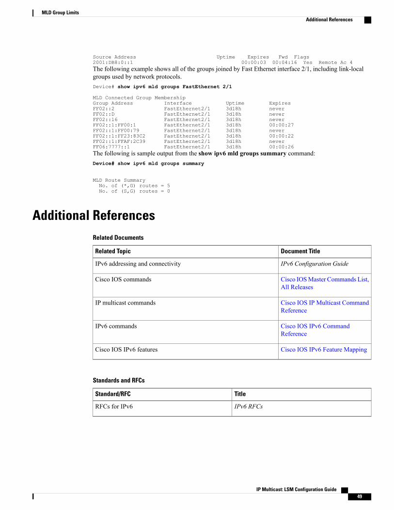
Source Address Uptime Expires Fwd Flags2001:DB8:0::1 00:00:03 00:04:16 Yes Remote Ac 4The following example shows all of the groups joined by Fast Ethernet interface 2/1, including link-localgroups used by network protocols.Device# show ipv6 mld groups FastEthernet 2/1
MLD Connected Group MembershipGroup Address Interface Uptime ExpiresFF02::2 FastEthernet2/1 3d18h neverFF02::D FastEthernet2/1 3d18h neverFF02::16 FastEthernet2/1 3d18h neverFF02::1:FF00:1 FastEthernet2/1 3d18h 00:00:27FF02::1:FF00:79 FastEthernet2/1 3d18h neverFF02::1:FF23:83C2 FastEthernet2/1 3d18h 00:00:22FF02::1:FFAF:2C39 FastEthernet2/1 3d18h neverFF06:7777::1 FastEthernet2/1 3d18h 00:00:26The following is sample output from the show ipv6 mld groups summary command:Device# show ipv6 mld groups summary
MLD Route SummaryNo. of (*,G) routes = 5No. of (S,G) routes = 0
Additional ReferencesRelated Documents
Document TitleRelated Topic
IPv6 Configuration GuideIPv6 addressing and connectivity
Cisco IOSMaster Commands List,All Releases
Cisco IOS commands
Cisco IOS IP Multicast CommandReference
IP multicast commands
Cisco IOS IPv6 CommandReference
IPv6 commands
Cisco IOS IPv6 Feature MappingCisco IOS IPv6 features
Standards and RFCs
TitleStandard/RFC
IPv6 RFCsRFCs for IPv6
IP Multicast: LSM Configuration Guide 49
MLD Group LimitsAdditional References

MIBs
MIBs LinkMIB
To locate and downloadMIBs for selected platforms,Cisco IOS releases, and feature sets, use Cisco MIBLocator found at the following URL:
http://www.cisco.com/go/mibs
Technical Assistance
LinkDescription
http://www.cisco.com/cisco/web/support/index.htmlThe Cisco Support and Documentation websiteprovides online resources to download documentation,software, and tools. Use these resources to install andconfigure the software and to troubleshoot and resolvetechnical issues with Cisco products and technologies.Access to most tools on the Cisco Support andDocumentation website requires a Cisco.com user IDand password.
Feature Information for MLD Group LimitsThe following table provides release information about the feature or features described in this module. Thistable lists only the software release that introduced support for a given feature in a given software releasetrain. Unless noted otherwise, subsequent releases of that software release train also support that feature.
Use Cisco Feature Navigator to find information about platform support and Cisco software image support.To access Cisco Feature Navigator, go to www.cisco.com/go/cfn. An account on Cisco.com is not required.
Table 3: Feature Information for MLD Group Limits
Feature InformationReleasesFeature Name
The IPv6MLDgroup limits featureprovides global and per-interfaceMLD join limits.
The following commands wereintroduced or modified: ipv6 mldlimit, ipv6 mld state-limit.
12.2(33)SRE
12.2(50)SY
12.4(2)T
15.0(1)S
15.0(1)SY
15.1(1)SY
Cisco IOS XE Release 2.6
MLD Group Limits
IP Multicast: LSM Configuration Guide50
MLD Group LimitsFeature Information for MLD Group Limits

C H A P T E R 5MLDP In-Band Signaling/Transit Mode
This module contains information for configuring Multicast Label Distribution Protocol (MLDP) in-bandsignaling to enable the MLDP core to create (S,G) or (*,G) state without using out-of-band signaling suchas Border Gateway protocol (BGP) or Protocol Independent Multicast (PIM).
• Finding Feature Information, page 51
• Restrictions for MLDP In-Band Signaling, page 51
• Information About MLDP In-Band Signaling/Transit Mode, page 52
• How to Configure MLDP In-Band Signaling/Transit Mode, page 52
• Additional References, page 53
• Configuration Examples for MLDP In-Band Signaling/Transit Mode, page 54
• Feature Information for MLDP In-Band Signaling/Transit Mode, page 60
Finding Feature InformationYour software release may not support all the features documented in this module. For the latest caveats andfeature information, see Bug Search Tool and the release notes for your platform and software release. Tofind information about the features documented in this module, and to see a list of the releases in which eachfeature is supported, see the feature information table.
Use Cisco Feature Navigator to find information about platform support and Cisco software image support.To access Cisco Feature Navigator, go to www.cisco.com/go/cfn. An account on Cisco.com is not required.
Restrictions for MLDP In-Band Signaling• MLDP in-band signaling supports SOURCE-SPECIFIC MULTICAST (SSM) multicast traffic only.
• MLDP in-band signaling is not supported in the sameVRF for which RosenModelMLDP-basedMVPNor GRE-based MVPN is configured.
IP Multicast: LSM Configuration Guide 51

Information About MLDP In-Band Signaling/Transit Mode
MLDP In-Band Signaling/Transit ModeMulticast Label Distribution Protocol (MLDP)-supported multicast VPN (MVPN) allows VPN multicaststreams to be aggregated over a VPN-specific tree. No customer state is created in the MLDP core;, there isonly state for default and data multicast distribution trees (MDTs). In certain scenarios, the state created forVPN streams is limited and does not appear to be a risk or limiting factor. In these scenarios, MLDP can buildin-band MDTs that are transit Label Switched Paths (LSPs).
Trees used in a VPN space are MDTs. Trees used in the global table are transit point-to-multipoint (P2MP)or multipoint-to-multipoint (MP2MP) LSPs. In both cases, a single multicast stream (VPN or not) is associatedwith a single LSP in the MPLS core. The stream information is encoded in the Forwarding Equivalence Class(FEC) of the LSP. This is in-band signaling.
MLDP in-band signaling uses access control lists (ACLs) with the range of themulticast (S, G) to be transportedby theMLDP LSP. Each multicast channel (S, G) maps, one-to-one, to each tree in the in-band tree. The (S,G)join is registered in the Multicast Routing Information Base (MRIB), which is a client of MLDP. Each MLDPLSP is identified by the FEC of [(S,G) + RD], where RD is the Route Distinquisher (RD) obtained from BGP.This differs from MLDP-based MVPN, where the identity is in a FEC of [MDT #, VPN ID, Tree #]).
The ingress Provider Edge (PE) device uses the FEC to decode the stream information and associate themulticast stream with the LSP (in the FEC). This service model is only applicable for transporting ProtocolIndependent Multicast (PIM) source-specific multicast (SSM) traffic. There is no need to run PIM over theLSP because the stream signaling is done in-band.
The MLDP In-Band Signaling/Transit Mode feature is supported on IPv4 networks. MLDP in-band signalingand MLDP-based MVPN cannot be supported in the same VRF.
How to Configure MLDP In-Band Signaling/Transit Mode
Enabling In-Band Signaling on a PE Device
Before You Begin
• VRF instances for in-band signaling must be configured.
• Access control lists (ACLs) for controlling streams must be configured.
SUMMARY STEPS
1. enable2. configure terminal3. Use one of the following commands:
• ip multicast [vrf vrf] mpls mldp [range acl]
• ipv6 multicast [vrf vrf] mpls mldp
IP Multicast: LSM Configuration Guide52
MLDP In-Band Signaling/Transit ModeInformation About MLDP In-Band Signaling/Transit Mode

DETAILED STEPS
PurposeCommand or Action
Enables privileged EXEC mode.enable
Example:Device> enable
Step 1
• Enter your password if prompted.
Enters global configuration mode.configure terminal
Example:Device# configure terminal
Step 2
Brings up the MLDPMRIB process and registers MLDP withthe MRIB.
Use one of the following commands:Step 3
• ip multicast [vrf vrf] mpls mldp [range acl]• To enable in-band signaling globally, use this commandwithout the vrf vrf keyword and argument combination.• ipv6 multicast [vrf vrf] mpls mldp
• IPv4 only: To identify streams for in-band signaling, usethis command with the range keyword on the egress PE.Example:
Device (config)# ip multicast vrf vrf1 mplsmldp
Device (config)# ipv6 multicast vrf vrf1 mplsmldp
Additional ReferencesRelated Documents
Document TitleRelated Topic
IPv6 Configuration GuideIPv6 addressing and connectivity
Cisco IOS Master Commands List, All ReleasesCisco IOS commands
Cisco IOS IP Multicast Command ReferenceIP multicast commands
Cisco IOS IPv6 Command ReferenceIPv6 commands
Cisco IOS IPv6 Feature MappingCisco IOS IPv6 features
IP Multicast: LSM Configuration Guide 53
MLDP In-Band Signaling/Transit ModeAdditional References

Standards and RFCs
TitleStandard/RFC
IPv6 RFCsRFCs for IPv6
MIBs
MIBs LinkMIB
To locate and downloadMIBs for selected platforms,Cisco IOS releases, and feature sets, use Cisco MIBLocator found at the following URL:
http://www.cisco.com/go/mibs
Technical Assistance
LinkDescription
http://www.cisco.com/cisco/web/support/index.htmlThe Cisco Support and Documentation websiteprovides online resources to download documentation,software, and tools. Use these resources to install andconfigure the software and to troubleshoot and resolvetechnical issues with Cisco products and technologies.Access to most tools on the Cisco Support andDocumentation website requires a Cisco.com user IDand password.
Configuration Examples for MLDP In-Band Signaling/TransitMode
Example: In-Band Signaling on PE1PE1# show running-configBuilding configuration...
Current configuration : 8247 bytes!! Last configuration change at 12:44:13 IST Thu Nov 15 2012!
hostname PE1!mls ipv6 vrf!vrf definition vrf1rd 1:1vpn id 1:1
IP Multicast: LSM Configuration Guide54
MLDP In-Band Signaling/Transit ModeConfiguration Examples for MLDP In-Band Signaling/Transit Mode

route-target export 1:1route-target import 1:1!address-family ipv4route-target export 1:1route-target import 1:1exit-address-family!address-family ipv6route-target export 1:1route-target import 1:1exit-address-family!
ip multicast-routingip multicast-routing vrf vrf1ip multicast hardware-switching replication-mode egressip multicast mpls mldpip multicast vrf vrf1 mpls mldp!!!ipv6 unicast-routingipv6 multicast-routingipv6 multicast-routing vrf vrf1ipv6 multicast rpf use-bgpipv6 multicast mpls source Loopback0ipv6 multicast mpls mldpipv6 multicast vrf vrf1 rpf use-bgpipv6 multicast vrf vrf1 mpls source Loopback0ipv6 multicast vrf vrf1 mpls mldp!!vtp domain ciscovtp mode offmpls label protocol ldpmpls ldp graceful-restartmls flow ip interface-fullno mls flow ipv6mls rate-limit multicast ipv4 igmp 100 10mls cef error action resetmls mpls tunnel-recirmultilink bundle-name authenticated!!!!spanning-tree mode pvstspanning-tree extend system-idno diagnostic bootup level!redundancymain-cpuauto-sync running-configmode sso!
vlan internal allocation policy ascendingvlan access-log ratelimit 2000!interface Loopback0ip address 1.1.1.1 255.255.255.255ip pim sparse-modeip ospf 100 area 0ipv6 address 1::1:1:1/64ipv6 enable!...!interface GigabitEthernet2/0/0.1encapsulation dot1Q 2
IP Multicast: LSM Configuration Guide 55
MLDP In-Band Signaling/Transit ModeExample: In-Band Signaling on PE1

vrf forwarding vrf1ip address 192.0.2.1 255.255.255.0ip pim sparse-modeip igmp version 3ipv6 address FE80::10:1:1 link-localipv6 address 2001:DB8::/64ipv6 enable!interface GigabitEthernet2/0/0.2000encapsulation dot1Q 2000ip address 192.0.2.2 255.255.255.0ip pim sparse-modeip igmp version 3ipv6 address 2001:DB8:0:1/64ipv6 enable!...interface GigabitEthernet2/0/12ip address 192.0.2.3 255.255.255.0ip pim sparse-modeip ospf 100 area 0ipv6 address 2001:DB8::/64ipv6 enablempls ipmpls label protocol ldpno mls qos trust!!!router ospf 100router-id 1.1.1.1!router bgp 100bgp log-neighbor-changesneighbor 2.2.2.2 remote-as 100neighbor 2.2.2.2 update-source Loopback0neighbor 3.3.3.3 remote-as 100neighbor 3.3.3.3 update-source Loopback0neighbor 4.4.4.4 remote-as 100neighbor 4.4.4.4 update-source Loopback0!address-family ipv4redistribute staticredistribute connectedneighbor 2.2.2.2 activateneighbor 2.2.2.2 send-community bothneighbor 3.3.3.3 activateneighbor 3.3.3.3 send-community bothneighbor 4.4.4.4 activateneighbor 4.4.4.4 send-community bothexit-address-family!address-family vpnv4neighbor 2.2.2.2 activateneighbor 2.2.2.2 send-community extendedneighbor 3.3.3.3 activateneighbor 3.3.3.3 send-community extendedneighbor 4.4.4.4 activateneighbor 4.4.4.4 send-community extendedexit-address-family!address-family ipv4 mdtneighbor 2.2.2.2 activateneighbor 2.2.2.2 send-community extendedneighbor 3.3.3.3 activateneighbor 3.3.3.3 send-community extendedneighbor 4.4.4.4 activateneighbor 4.4.4.4 send-community extendedexit-address-family!address-family ipv6
IP Multicast: LSM Configuration Guide56
MLDP In-Band Signaling/Transit ModeExample: In-Band Signaling on PE1

redistribute connectedneighbor 2.2.2.2 activateneighbor 2.2.2.2 send-community extendedneighbor 2.2.2.2 send-labelneighbor 3.3.3.3 activateneighbor 3.3.3.3 send-community extendedneighbor 3.3.3.3 send-labelneighbor 4.4.4.4 activateneighbor 4.4.4.4 send-community extendedneighbor 4.4.4.4 send-labelexit-address-family!address-family vpnv6neighbor 2.2.2.2 activateneighbor 2.2.2.2 send-community extendedneighbor 3.3.3.3 activateneighbor 3.3.3.3 send-community extendedneighbor 4.4.4.4 activateneighbor 4.4.4.4 send-community extendedexit-address-family!address-family ipv4 vrf vrf1redistribute connectedexit-address-family!address-family ipv6 vrf vrf1redistribute connectedexit-address-family!no ip forward-protocol nd!no ip http serverno ip http secure-serverip pim ssm defaultip pim mpls source Loopback0ip pim vrf vrf1 ssm defaultip pim vrf vrf1 mpls source Loopback0ip route 192.0.2.25 255.255.255.255 7.37.0.1!!mpls ldp router-id Loopback0 force!!!end
Example: In-Band Signaling on PE2PE2# show running-configBuilding configuration...
Current configuration : 7609 bytes!! Last configuration change at 13:18:45 IST Thu Nov 15 2012!hostname PE2!mls ipv6 vrf!vrf definition vrf1rd 1:1vpn id 1:1route-target export 1:1route-target import 1:1!address-family ipv4route-target export 1:1route-target import 1:1exit-address-family!
IP Multicast: LSM Configuration Guide 57
MLDP In-Band Signaling/Transit ModeExample: In-Band Signaling on PE2

address-family ipv6route-target export 1:1route-target import 1:1exit-address-family!...!ip multicast-routingip multicast-routing vrf vrf1ip multicast hardware-switching replication-mode egressip multicast mpls mldpip multicast vrf vrf1 mpls mldp!!!ipv6 unicast-routingipv6 multicast-routingipv6 multicast-routing vrf vrf1ipv6 multicast rpf use-bgpipv6 multicast mpls source Loopback0ipv6 multicast mpls mldpipv6 multicast vrf vrf1 rpf use-bgpipv6 multicast vrf vrf1 mpls source Loopback0ipv6 multicast vrf vrf1 mpls mldp!!vtp domain isbu-devtestvtp mode offmpls label protocol ldpmpls ldp graceful-restartmls flow ip interface-fullno mls flow ipv6mls cef error action resetmultilink bundle-name authenticated!!!!spanning-tree mode pvstspanning-tree extend system-iddiagnostic bootup level minimal!redundancymain-cpuauto-sync running-configmode sso!!!interface Loopback0ip address 4.4.4.4 255.255.255.255ip pim sparse-modeip ospf 100 area 0ipv6 enable!...!interface GigabitEthernet3/0/3.1encapsulation dot1Q 2vrf forwarding vrf1ip address 192.0.2.1 255.255.255.0ip pim sparse-modeip igmp version 3ipv6 address FE80::30:1:1 link-localipv6 address 2001:DB8::/64ipv6 enable!interface GigabitEthernet3/0/3.2000encapsulation dot1Q 2000
IP Multicast: LSM Configuration Guide58
MLDP In-Band Signaling/Transit ModeExample: In-Band Signaling on PE2

ip address 192.0.2.2 255.255.255.0ip pim sparse-modeip igmp static-group 232.1.1.1 source 50.0.0.2ip igmp version 3ipv6 address 2001:DB8:0:1/64ipv6 enable!...!interface GigabitEthernet4/15ip address 192.0.2.3 255.255.255.0ip pim sparse-modeip ospf 100 area 0ipv6 address 2001:DB8::/64ipv6 enablempls ipmpls label protocol ldp!...!interface Vlan1no ip addressshutdown!router ospf 100router-id 4.4.4.4!router bgp 100bgp log-neighbor-changesneighbor 1.1.1.1 remote-as 100neighbor 1.1.1.1 update-source Loopback0neighbor 2.2.2.2 remote-as 100neighbor 2.2.2.2 update-source Loopback0neighbor 3.3.3.3 remote-as 100neighbor 3.3.3.3 update-source Loopback0!address-family ipv4redistribute staticredistribute connectedneighbor 1.1.1.1 activateneighbor 1.1.1.1 send-community bothneighbor 2.2.2.2 activateneighbor 2.2.2.2 send-community bothneighbor 3.3.3.3 activateneighbor 3.3.3.3 send-community bothexit-address-family!address-family vpnv4neighbor 1.1.1.1 activateneighbor 1.1.1.1 send-community extendedneighbor 2.2.2.2 activateneighbor 2.2.2.2 send-community extendedneighbor 3.3.3.3 activateneighbor 3.3.3.3 send-community extendedexit-address-family!address-family ipv4 mdtneighbor 1.1.1.1 activateneighbor 1.1.1.1 send-community extendedneighbor 2.2.2.2 activateneighbor 2.2.2.2 send-community extendedneighbor 3.3.3.3 activateneighbor 3.3.3.3 send-community extendedexit-address-family!address-family ipv6redistribute connectedneighbor 1.1.1.1 activateneighbor 1.1.1.1 send-community extended
IP Multicast: LSM Configuration Guide 59
MLDP In-Band Signaling/Transit ModeExample: In-Band Signaling on PE2

neighbor 1.1.1.1 send-labelneighbor 2.2.2.2 activateneighbor 2.2.2.2 send-community extendedneighbor 2.2.2.2 send-labelneighbor 3.3.3.3 activateneighbor 3.3.3.3 send-community extendedneighbor 3.3.3.3 send-labelexit-address-family!address-family vpnv6neighbor 1.1.1.1 activateneighbor 1.1.1.1 send-community extendedneighbor 2.2.2.2 activateneighbor 2.2.2.2 send-community extendedneighbor 3.3.3.3 activateneighbor 3.3.3.3 send-community extendedexit-address-family!address-family ipv4 vrf vrf1redistribute connectedexit-address-family!address-family ipv6 vrf vrf1redistribute connectedexit-address-family!ip forward-protocol nd!no ip http serverno ip http secure-serverip pim ssm defaultip pim mpls source Loopback0ip pim vrf vrf1 ssm defaultip pim vrf vrf1 mpls source Loopback0ip route 192.0.2.25 255.255.255.255 7.37.0.1!!mpls ldp router-id Loopback0 force!!...!!end
Feature Information for MLDP In-Band Signaling/Transit ModeThe following table provides release information about the feature or features described in this module. Thistable lists only the software release that introduced support for a given feature in a given software releasetrain. Unless noted otherwise, subsequent releases of that software release train also support that feature.
Use Cisco Feature Navigator to find information about platform support and Cisco software image support.To access Cisco Feature Navigator, go to www.cisco.com/go/cfn. An account on Cisco.com is not required.
IP Multicast: LSM Configuration Guide60
MLDP In-Band Signaling/Transit ModeFeature Information for MLDP In-Band Signaling/Transit Mode

Table 4: Feature Information for MLDP In-Band Signaling/Transit Mode
Feature InformationReleasesFeature Name
Multicast Label DistributionProtocol (MLDP) in-band signalingsupports point-to-multipoint (P2P)and multipoint-to-multipoint(MP2MP) Label Switched Paths(LSPs) and enables theMLDP coreto create (S,G) or (*,G) statewithout using out-of-band signalingsuch as Border Gateway Protocol(BGP) or Protocol IndependentMulticast (PIM). This feature issupported for IPv4 and IPv6multicast groups.
The following commands wereintroduced or modified: ipmulticast mpls mldp, ipv6multicast mpls mldp.
15.3(1)S
Cisco IOS XE 3.14S
MLDP In-Band Signaling/TransitMode
IP Multicast: LSM Configuration Guide 61
MLDP In-Band Signaling/Transit ModeFeature Information for MLDP In-Band Signaling/Transit Mode

IP Multicast: LSM Configuration Guide62
MLDP In-Band Signaling/Transit ModeFeature Information for MLDP In-Band Signaling/Transit Mode

C H A P T E R 6HA Support for MLDP
TheHASupport forMLDP feature enables CiscoMulticast Label Distribution Protocol (MLDP) to checkpointsufficient signaling and forwarding information for repopulating the necessary database on a dual RouteProcessor (RP) platform onwhich Stateful Switchover/Nonstop Forwarding (SSO/NSF) and Label DistributionProtocol (LDP) Graceful Restart are configured, after a switchover.
• Finding Feature Information, page 63
• Prerequisites for HA Support for MLDP, page 63
• Restrictions for HA Support for MLDP, page 64
• Information About HA Support for MLDP, page 64
• How to Montior HA Support for MLDP, page 64
• Additional References, page 66
• Feature Information for HA Support for MLDP, page 67
Finding Feature InformationYour software release may not support all the features documented in this module. For the latest caveats andfeature information, see Bug Search Tool and the release notes for your platform and software release. Tofind information about the features documented in this module, and to see a list of the releases in which eachfeature is supported, see the feature information table.
Use Cisco Feature Navigator to find information about platform support and Cisco software image support.To access Cisco Feature Navigator, go to www.cisco.com/go/cfn. An account on Cisco.com is not required.
Prerequisites for HA Support for MLDP• Stateful Switchover/Nonstop Forwarding (SSO/NSF) and LDP Graceful Restart must be configured onthe dual Route Processor (RP) platform.
• LDP Graceful Restart must be configured on the NSF router peers.
IP Multicast: LSM Configuration Guide 63

• The Cisco IOS release software installed on the active and standby RPs must support MLDP-basedMVPN and HA Support for MLDP.
Restrictions for HA Support for MLDP• If Label Distribution Protocol (LDP) Graceful Restart is not enabled on the dual Route Processor (RP)platform, Nonstop Forwarding (NSF) peers will remove existing forwarding and label information fromtheirMulticast Label Distribution Protocol (MLDP) database entries immediately following a switchover.
Information About HA Support for MLDPThe HA Support for MLDP feature enables MLDP to checkpoint label forwarding or path set information.To support NSF, MLDP uses existing PIM HA architecture to checkpoint the information to the standby RP.
MDT data group creation is a dynamic event triggered by traffic exceeding a specified threshold. When thethreshold is exceeded (requiring an MDT data group to be created) or when traffic falls below the threshold(requiring the MDT data group to be deleted), the router detecting the event creates, deletes, or updates anMDT data "send" entry, creates the corresponding (S,G) state, if necessary, and sends a message to PE peersto create, delete, or update a corresponding MDT data "receive" entry and the corresponding (S,G) state.
The active RP will checkpoint the current state of the MLDP peer, paths to peers, root, paths to root, and thedatabase and replication/branch entry onto the standby RP and use this state to recreate the MLDP state aftera switchover.
How to Montior HA Support for MLDP
Displaying Check Pointed Information
SUMMARY STEPS
1. enable2. show mpls mldp ha database3. show mpls mldp ha database summary4. show mpls mldp ha neighbor5. show mpls mldp ha root6. show mpls mldp ha count
IP Multicast: LSM Configuration Guide64
HA Support for MLDPRestrictions for HA Support for MLDP

DETAILED STEPS
PurposeCommand or Action
Enables privileged EXEC mode.enable
Example:PE2> enable
Step 1
• Enter your password if prompted.
Displays checkpoint data information.show mpls mldp ha database
Example:PE2# show mpls mldp ha database
Step 2
Displays synched database information only.show mpls mldp ha database summary
Example:PE2# show mpls mldp ha database summary
Step 3
Displays information about synched peers.show mpls mldp ha neighbor
Example:PE2# show mpls mldp ha neighbor
Step 4
Displays synched root information.show mpls mldp ha root
Example:PE2# show mpls mldp ha root
Step 5
Displays number of trees.show mpls mldp ha count
Example:PE2# show mpls mldp ha count
Step 6
Displaying Data MDT Mappings for MLDP on Standby Device
SUMMARY STEPS
1. enable2. show ip pim vrf vrfmdt send3. show ip pim vrf vrfmdt recv
IP Multicast: LSM Configuration Guide 65
HA Support for MLDPDisplaying Data MDT Mappings for MLDP on Standby Device

DETAILED STEPS
PurposeCommand or Action
Enables privileged EXEC mode.enable
Example:PE1-standby> enable
Step 1
• Enter your password if prompted.
Displays data MDT mappings for MLDP.show ip pim vrf vrfmdt send
Example:PE1-standby# show ip pim vrf blue mdt send
Step 2
Displays data MDT mappings for MLDP.show ip pim vrf vrfmdt recv
Example:PE1-standby# show ip pim vrf blue mdt recv
Step 3
Additional ReferencesRelated Documents
Document TitleRelated Topic
Cisco IOSMaster Commands List,All Releases
Cisco IOS commands
Cisco IOS IP Multicast CommandReference
IP Multicast commands
High Availability ConfigurationGuide
Cisco HA
Standards and RFCs
TitleStandard/RFC
--No new or modified standards are supported, andsupport for existing standards has not been modified.
--No new or modified RFCs are supported, and supportfor existing RFCs has not been modified.
IP Multicast: LSM Configuration Guide66
HA Support for MLDPAdditional References

MIBs
MIBs LinkMIB
To locate and downloadMIBs for selected platforms,Cisco software releases, and feature sets, use CiscoMIB Locator found at the following URL:
http://www.cisco.com/go/mibs
--
Technical Assistance
LinkDescription
http://www.cisco.com/cisco/web/support/index.htmlThe Cisco Support and Documentation websiteprovides online resources to download documentation,software, and tools. Use these resources to install andconfigure the software and to troubleshoot and resolvetechnical issues with Cisco products and technologies.Access to most tools on the Cisco Support andDocumentation website requires a Cisco.com user IDand password.
Feature Information for HA Support for MLDPThe following table provides release information about the feature or features described in this module. Thistable lists only the software release that introduced support for a given feature in a given software releasetrain. Unless noted otherwise, subsequent releases of that software release train also support that feature.
Use Cisco Feature Navigator to find information about platform support and Cisco software image support.To access Cisco Feature Navigator, go to www.cisco.com/go/cfn. An account on Cisco.com is not required.
IP Multicast: LSM Configuration Guide 67
HA Support for MLDPFeature Information for HA Support for MLDP

Table 5: Feature Information for HA Support for MLDP
Feature InformationReleasesFeature Name
TheHASupport forMLDP featureenables Cisco Multicast LabelDistribution Protocol (MLDP) tocheckpoint sufficient signaling andforwarding information forrepopulating the necessary databaseon a dual Route Processor (RP)platform on which StatefulSwitchover/Nonstop Forwarding(SSO/NSF) and Label DistributionProtocol (LDP) Graceful Restartare configured, after a switchover.
The following commands wereintroduced or modified: show ippim mdt recv, show ip pim mdtsend, show mpls mldp hadatabase , show mpls mldp haneighbor, show mpls mldp haroot.
15.1(3)S
15.1(1)SY
Cisco IOS XE Release 3.8S
HA Support for MLDP
IP Multicast: LSM Configuration Guide68
HA Support for MLDPFeature Information for HA Support for MLDP