Embed Size (px)
Citation preview

1
IP-Masthead Configuration 1. RS232 Cable The current version of IP-Masthead (z18) supports t he only way of configuration = via RS232 cable. Please build a cable according t o the picture below:
CANON 9 (Female) Front View
2 3 5

2
2. Serial Port Terminal Software For serial communication with IP-Masthead can be us ed any Serial Port Terminal software you are familiar with. If you are not sure any usable Serial Port Terminal software is installed on your computer, then we recommend to install TeraTer m (freeware), for example from the following link (version 4.71): http://sourceforge.jp/frs/redir.php?m=jaist&f=%2Ftt ssh2%2F53081%2Fteraterm-4.71.exe Select “Custom Installation” and un-check all optio ns so that only option “Tera Term & Macro” remains checked. Complete the installation and start the application . If dialog “Tera Term: New connection” appears, clic k CANCEL. In the menu select: File -> New connection, choose radio-button “Serial” and select the COM p ort connected to IP-Masthead and click OK.
In the menu select: Setup -> Serial Port, adjust values according to the following screenshot and click OK.

3
In the menu select: Setup -> Terminal, adjust values according to the following screenshot and click OK.
The dialog may also look a bit different, according to the operating system version and its l ook set:

4
In the menu select: Setup -> Font, adjust values according to the following screenshot and click OK. Value 10 in the “Size:” edit-box must be entered ma nually.
In the menu select: Setup -> Save Setup, leave the File Name unchanged and click SAVE. All settings are saved and will be used as a defaul t on next run. Close the TeraTerm application.

5
Check the TeraTerm software has been installed & se t correctly and the proper COM port is connected to IP-Masthead:
- start TeraTerm (or other terminal) - connect IP-Masthead to the selected COM port - connect Power Supply to the IP-Masthead
IP-Masthead should print some text on Power-Up, lik e:
The first line of the initial text is information a bout the firmware version. If any troubles with IP-Masthead occur and you need help from Luminite, then please tell us this first line. Try to write some commands to verify communication. Press ENTER, write text HELLO + press ENTER. Answer “ACK” should be received. Commands are not c ase sensitive. hello ACK ?info ACK Luminite Electronics Ltd; Copyright 2011 [email protected] Firmware Version: 5.01 (DZ) Last Revision Date: Aug 18 2011

6
3. Router settings Your local network (LAN) is connected to Internet v ia Router (DSL Modem). Usually Routers have Web-pages-based interface. All Router settings can be done through this interf ace, using an ordinary internet browser like Internet Ex plorer. You must know (find) the IP address of your router and Password. IP address can be usually found in User’s Guide of your Router, most people also use default password. We will provide examples of setting of 2 routers,
a) Belkin F5D7633 Wireless DSL Router b) Huawei EchoLife HG520I
These 2 examples should give you also sufficient gu ide for setting of other types of routers. 3A. Belkin F5D7633 Wireless DSL Router Default IP address of this router’s web-interface i s 10.1.1.1 . Start your internet browser (any) and enter 10.1.1. 1 in the address line. A screen like the following should appear.
Enter the proper Password and click on [Submit].

7
In the menu select LAN Setup / LAN Settings.
Important informations from this page are:
- IP Address (of the Router) is 10.1.1.1 and Subnet M ask is 255.255.255.0, => IP Addresses range 10.1.1.1 to 10.1.1.255 are ac cessible by the Router (10.1.1.1 is Router itself).
- DHCP Server is Enabled => any device connected to t he Local Network (LAN) can get its IP Address from the router. Including o ur IP-Masthead, if the DHCP is enabled in Masthead’s configuration menu.
- Router uses IP Addresses range 10.1.1.111 to 10.1.1 .127 for DHCP. Now we can choose an IP Address for our IP-Masthead . Prefered is to have DHCP Disabled in the Masthead’s configuration menu (no matter whether DHCP Enabled or Disabled on Rout er). Then the IP-Masthead will use static IP Address (en tered in Masthead’s configuration); the IP Address will be permanent an d will never change, even if Masthead is off for several months (unlike address assigned via DHCP). The IP-Address must be in the range accessible by the Router (10.1.1.1 to 10.1.1.255), must be out of the DHCP r ange (10.1.1.111 to 10.1.1.127) to not collide with DHCP-assigned addre sses, and must not collide with any other static IP-Address used on the LAN. => we can choose any IP-Address between 10.1.1.2 to 10.1.1.110, or 10.1.1.128 to 10.1.1.255 . Please check IP-Addresses of all IP-devices (com puters) on your LAN to avoid IP-Address collision. � we choose 10.1.1.150 The process of IP-Masthead’s configuration is descr ibed in other chapter, now we will assume we have choosen IP-Addres 10.1.1 .150 .

8
IP-Masthead operates as a TCP Server. The TCP Server is listening on port 9761 (can be ch anged in Masthead’s configuration) for commands (like HELLO, HELP, ?INF O, ...). To make the IP-Masthead accessible from Internet (n ot only from our LAN) we must make a procedure called “ Port Forwarding ”. In the menu select Firewall / Virtual Servers.
Click on the [Add] to add a new item to the table.

9
Fill the form this way and then click [Add]:

10
Any name of new item can be entered in edit-box “Cu stom Server”, we have choosen identification “IP_Masthead”. The “Server IP Address” is the address choosen in t he previous step = 10.1.1.150 . “External Port Start” and “External Port End” deter mine the range of ports that are supposed to be forwarded to the given IP-Addres s. In our case we have to select range 9760 to 9763. Port 9760 is used for Bootloader/Logfile operations . Port 9761 is used for text output / commands input; client (eg. telnet) connected to this port will rec eive exactly the same text that is printed via UART (RS232) output = messages like: CALL: PIR 47, Batt 100, mRSSI 7, Type 1, Pulse 1, Ver 6 CALL: PIR 38, Batt 100, mRSSI 8, Type 1, Pulse 1, Ver 6 ALARM: PIR 9, Status -T--- ALARM: PIR 8, Status D---- All data sent from client to the Port 9761 are proc essed as a commands. Exactly the same way as data received from UART (RS 232) input (data from Port 9761 and UART are merged in a commo n command line buffer). Ports 9762 and 9763 are reserved for future use. Following screen appears after adding the new recor d:
Router configuration is complete. Click on the [Logout] on the bar on the top of the screen.
11
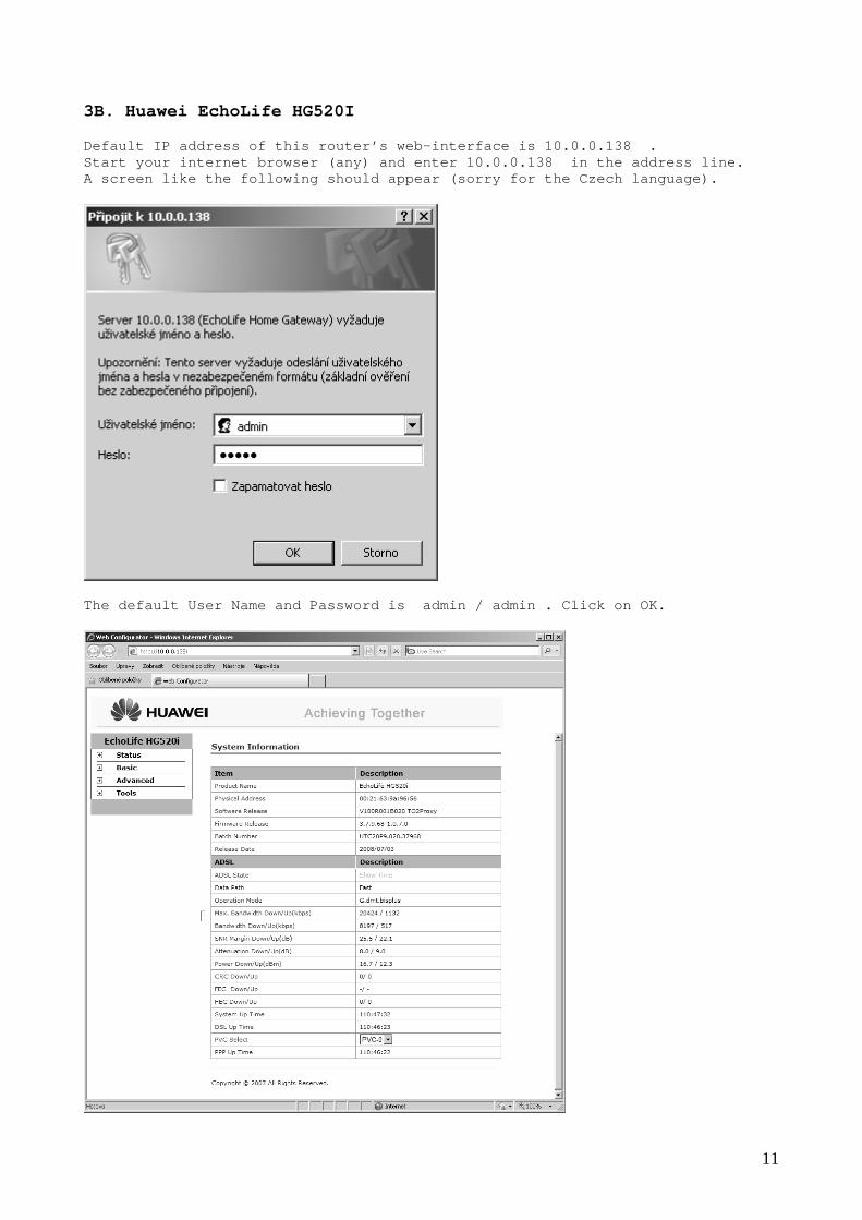
3B. Huawei EchoLife HG520I Default IP address of this router’s web-interface i s 10.0.0.138 . Start your internet browser (any) and enter 10.0.0. 138 in the address line. A screen like the following should appear (sorry fo r the Czech language).
The default User Name and Password is admin / admi n . Click on OK.

12
In the menu expand Basic and select LAN Setting .
Important informations from this page are:
- IP Address (of the Router) is 10.0.0.138 and Subnet Mask is 255.255.255.0, => IP Addresses range 10.0.0.1 to 10.0.0.255 are ac cessible by the Router (10.0.0.138 is Router itself).

13
In the menu expand Basic and select DHCP.
Important informations from this page are:
- DHCP Server is Enabled => any device connected to t he Local Network (LAN) can get its IP Address from the router. Including o ur IP-Masthead, if the DHCP is enabled in Masthead’s configuration menu.
- Router uses IP Addresses range 10.0.0.1 to 10.0.0.3 2 for DHCP (Client IP Pool Starting Address = 10.0.0.1 , Size of Client IP Pool = 32, so total amount of 32 addresses for DHCP).
- DNS Servers (Primary and Secondary) are not assigne d (nevermind) Now we can choose an IP Address for our IP-Masthead . Prefered is to have DHCP Disabled in the Masthead’s configuration menu (no matter whether DHCP Enabled or Disabled on Rout er). Then the IP-Masthead will use static IP Address (en tered in Masthead’s configuration); the IP Address will be permanent an d will never change, even if Masthead is off for several months (unlike address assigned via DHCP).

14
The IP-Address must be in the range accessible by t he Router (10.0.0.1 to 10.0.0.255), must be out of the DHCP r ange (10.0.0.1 to 10.0.0.32) to not collide with DHCP-assigned addresses, and mu st not collide with any other static IP-Address used on the LAN. => we can choose any IP-Address between 10.0.0.33 t o 10.0.0.255, excluding 10.0.0.138 (the Router itself). Please check IP-Addresses of all IP-devices (com puters) on your LAN to avoid IP-Address collision. � we choose 10.0.0.50 The process of IP-Masthead’s configuration is descr ibed in other chapter, now we will assume we have choosen IP-Addres 10.0.0 .50 . IP-Masthead operates as a TCP Server. The TCP Server is listening on port 9761 (can be ch anged in Masthead’s configuration) for commands (like HELLO, HELP, ?INF O, ...). To make the IP-Masthead accessible from Internet (n ot only from our LAN) we must make a procedure called “ Port Forwarding ”. In the menu expand Basic and select NAT.
15
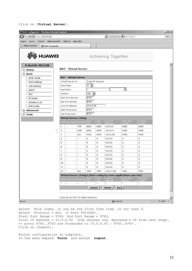
Click on [ Virtual Server ].
Select Rule Index, it can be the first free item, in our case 3. Select Protocol = ALL (= both TCP+UDP). Start Port Range = 9760, End Port Range = 9763, Local IP Address = 10.0.0.50 (the choosen one, Mas thead’s IP from last step), => ports 9760..9763 are forwarded to 10.0.0.50 : 97 60..9763 . Click on [Submit]. Router configuration is complete. In the menu expand Tools and select Logout .

16
4. How to restore Default Factory Settings
- disconnect Power Supply of the IP-Masthead - start TeraTerm (or other terminal) - connect IP-Masthead to the selected COM port - press Button 1 and hold it down
(Button 1 is on the IP-Masthead above the BNC conne ctor, the left one) - connect Power Supply to the IP-Masthead (Button 1 s till down) - keep holding the Button 1 down for further 5 second s after Power-Up,
until Masthead prints message: BUTTON0 held for more than 5 seconds. Default sett ings restored.
- release the Button 1, done
5. How to enter IP-Masthead’s Configuration
- disconnect Power Supply of the IP-Masthead - start TeraTerm (or other terminal) - connect IP-Masthead to the selected COM port - press Button 1 and hold it down
(Button 1 is on the IP-Masthead above the BNC conne ctor, the left one) - connect Power Supply to the IP-Masthead (Button 1 s till down) - keep holding the Button 1 down for further 1 second after Power-Up,
not longer ! - release the Button 1 , a screen with Configuration Options appears

17
This example is showing Default Configuration value s = after procedure described in chapter 4. (Default Factory Settings restored).
6. How to get values needed for IP-Masthead’s Configuration An easy way to get Gateway Address, Subnet Mask, DN S (both Primary and Secondary) is to copy these values from your comput er. It is connected to the same LAN as the IP-Masthead. Go to the Windows Start menu, select “Command Promp t”. If this item is not contained in your Start menu, t hen there should be “Run”. Select it. A dialog appears, enter command “cmd” + click on [OK]. It will start command prompt (DOS command line).

18
No matter what (working) directory is shown, enter a command: “ipconfig /all” + press Enter.
Useful informations are these:
- Subnet Mask = 255.255.255.0 - Default Gateway = 10.1.1.1
(it is the IP-Address of the Belkin F5D7633 Wireles s DSL Router, described in chapter 3A)
- DNS Servers are 10.1.1.100 and 208.67.222.222 We will use these values for IP-Masthead’s Configur ation.

19
7. IP-Masthead’s Configuration Follow the procedure described in chapter 5 to ente r the IP-Masthead’s Configuration. The menu with options 1/2/3/4/5/6/7/ 8/9/A/B/C/D/E/F/S appears on the terminal screen. [1:] choose number 1 to change 16b Serial Number . The serial number 57674 (from the example, cha pter 5) is 0xE14A hexadecimally. It determines last 2 bytes of MAC-Address. The full MAC-Address of this IP-Masthead is th en 00-04-A3-00-E1-4A (first 4 bytes are always 00-04-A3-00). The default Serial Number is randomly generate d, very likely is unique for each peace of IP-Masthead sold. The only meaningful reason for changing this v alue manually is if you find more Mastheads have the same Serial Numbe r, so they would collide. Then you can enter any value range 0..65535 . [2:] choose number 2 to change Host Name . Host Name = NetBIOS Name, each IP-device on th e LAN should have unique name. It serves for identification. If you pla n to have only 1 IP-Masthead installed on your LAN, then the default name “ IPMASTHEAD” may remain unchanged. Optionally, any up-to 16-characters long name can be entered, must start with a letter (a..z / A..Z), other characters can be letters or numbers (eg. “IPMASTHEAD2”, “masthead77”,.. ). [3:] choose number 3 to change Static IP Address . Chapter 3A / 3B describes the rules for choosi ng a Static IP-Address suitable for IP-Masthead in your LAN. Enter th e IP-Address choosen here. [4:] choose number 4 to change Static Gateway Address . Copy the value obtained via “ipconfig /all”, s ee chapter 6. It is the value “Default Gateway”. [5:] choose number 5 to change Static Subnet Mask . Copy the value obtained via “ipconfig /all”, s ee chapter 6. It is the value “Subnet Mask”. [6:] choose number 6 to change Static Primary DNS Server . Copy the value obtained via “ipconfig /all”, s ee chapter 6. It is the value “DNS Servers”, first line. [7:] choose number 7 to change Static Secondary DNS Server . Copy the value obtained via “ipconfig /all”, s ee chapter 6. It is the value “DNS Servers”, second line. If there is only one address after “DNS Server s”, then leave address 0.0.0.0 (= not specified). [8:] choose number 8 to Enable/Disable DHCP & IP Gleaning . Initial state (Default Factory Settings restor ed) is “DHCP Enabled”. Press number 8 to toggle to “DHCP Disabled”. Only then the Static IP Address edited by [3:] will be used. [9:] ignore this option, not supported in current f irmware version.

20
[A:] choose letter A/a to change TCP Password . The TCP Password protects the IP-Masthead agai nst unauthorized client connections. Password can consist of any chara cters, excluding SPACEs. Length max. 16 characters. If the Password starts with character ‘-‘ (m inus) then the connections to port 9761 are unprotected = Password is not required. It is useful for test/debug purposes (connecti on via “telnet”). If there is not ‘-‘ on the Password begin, t hen the access to port 9761 is protected. It means the client must send a special sequence of bytes (containing the Password) as a first data imme diately after connection established. If the correct sequence is not re ceived within 10 seconds after connection, then then Masthead (TCP Serv er) closes the connection. Example: TCP Password = KingKong+17! (only 1 2 of 16 characters used). The client must send immediatelly after connec tion following sequence: “PW=KingKong+17!” + (4 * byte 0x00) The Password “KingKong+17!” has only 12 charac ters, the missing 4 characters are replaced with byt es 0x00. Total number of bytes to send is always 3+16=1 9 (3 [PW=] + 16 [password]). [B:] choose letter B/b to change TCP BasePort . Default ports used for IP-Masthead are 9760,97 61,9762,9763 => base=9760. Port 9760 is used for Bootloader/Logfile opera tions. Port 9761 is used for text output / commands i nput (TCP/UART bridge). Ports 9762 and 9763 are reserved for future us e. If any of these ports can not be used for any reason (collides with some application) then a differ ent Base can be set. [C:] choose letter C/c to change Interface Type . Value 0 means there is no 3rd Party Interface enabled. Value 1 activates interface for Dedicated Micr os DVRs. Other values are reserved for future use. [D:] choose letter D/d to change DVR Server IP . Some of 3rd Party Interfaces require the IP-Ma sthead to work as a TCP Client. In this cases, enter the TCP Server IP-Address (DVR). Leave IP-Address 0.0.0.0 if not needed (Interf ace Type = 0). [E:] choose letter E/e to change DVR Server Port . Some of 3rd Party Interfaces require the IP-Ma sthead to work as a TCP Client. In this cases, enter the TCP Server IP-Port here. Leave IP-Port 0 if not needed (Interface Type = 0). [F:] choose letter F/f to change DVR Parameters . Each of 3rd Party Interfaces may require some additional parameters. Combination of up to 16 characters can be edit ed here. Usage may vary for each interface type. [S:] choose letter S/s to Save & Quit . After making all settings needed, press S to s tore the new values to EEPROM. If no change was made, then no writ ing to EEPROM will occur. Configuration menu is quitted and IP-Masthead proceeds to normal Operation, with the updated settings.

21
This screen example is showing real Configuration v alues: - Serial Number is left unchanged = 57674 (generated randomly)
(MAC-Address of this IP-Masthead is 00-04-A3-00-E1- 4A) - Host Name is left unchanged = IPMASTHEAD - IP-Address 10.1.1.150 was choosen in chapter 3A. - Gateway Address + Subnet Mask + Primary DNS + Secon dary DNS
were copied from the “ipconfig /all” response, see chapter 6: � Gateway Address = 10.1.1.1 � Subnet Mask = 255.255.255.0 � Primary DNS = 10.1.1.100 � Secondary DNS = 208.67.222.222 - DHCP is Disabled (so Static IP-Address 10.1.1.150 is to be used) - TCP Password “-NOPASSWORD” is left unchanged,
it starts with a ‘-‘ so the connection to port 9761 is unprotected (no password sequence “PW=-NOPASSWORD” required on new connection)
- TCP BasePort is left unchanged = 9760 (ports 9760,9761,9762,9763 are to be used)
- Interface Type = 1, => interface to Dedicated Micros DVR is enabl ed - DVR Server IP = 212.140.243.141, it is IP-Address of the DVR - DVR Server Port = 4000, it is port used by the DVR for TCP Server - DVR Parameters = ‘-‘ (left unchanged, no usage of this parameter)

22
8. Testing of IP-Masthead on Local Network For basic test of accessibility on LAN we can use W indows utility “ telnet ”. Go to the Windows Start menu, select “Command Promp t”. If this item is not contained in your Start menu, t hen there should be “Run”. Select it. A dialog appears, enter command “cmd” + click on [OK]. It will start command prompt (DOS command line). No matter what (working) directory is shown, enter a command: “ telnet 10.1.1.150 9761 ” + press Enter. (Use your Masthead’s IP-Address instead of the 10.1 .1.150, it is the value from the Configuration option [3:] . Also use different Port instead of the 9761 if you assigned value other then 9760 as a Configuration option [B:], then the Port must be value BasePort+1 ). Following example is showing connection to IP-Masth ead with IP-Address 10.0.0.50 (the Huawei router used, see chapter 3B; command: “telnet 10.0.0.50 9761”). The last line shows the MAC-Address and IP-Address of the (my) computer that has just connected to the IP-Masthead.
You can try to enter some commands (HELLO, HELP, ?I NFO, ..) and the IP-Masthead should execute them exactly the same wa y as if commands were entered from UART (RS232) terminal (TeraTerm). If the Masthead is still connected via RS232 cable and UART terminal is running, then the same text output should appear on both TEL NET & UART terminal screens. Command RESET causes reset of the Masthead, it has the same effect as power supply reconnecting => TCP connection is lost. Mast head needs about 3 seconds to restart the TCP Server again, user must close th e TELNET window and start a new one, to make new connection.

23
9. Testing of IP-Masthead on Internet For the outside world (public Internet), all comput ers of your LAN are accessible under one IP-Address, called “Public IP- Address”. How to get the Public IP-Address ? Enter www.whatismyip.com into address line of your browser.
As you can see, the Public IP-Address of the Lumini te Electronics is 62.3.230.199 . There should be permanently running one IP-Masthead here, serving for experiments. Try to connect to the IP-Masthead running in Lumini te’s office. Open the Command Prompt and enter following command : telnet 62.3.230.199 9761 You should try to connect to your IP-Masthead from public Internet. It means, you should give your Public IP-Address (found via www.whatismyip.com ) to somebody (your friend) who is somewhere else (in other company, other city, .. , not on your LAN ) and he should try the TELNET with your Public IP-Address. The similar way as you just tried to connect to the IP-Masthead running in Luminite’s office. Note 1: You can not use your Public IP-Address on your Local Network. Note 2: Connection from the outside world (public Internet) to your IP-Masthead will work only if your Router was correctl y configured; “Port Forwarding” must forward outer acces ses to ports 9760/1/2/3 to your Masthead’s IP-Address.