Embed Size (px)
Citation preview

01-3
ION 4-SPEEDKYRON 2010.01
3410-01
3410-01ION 4-SPEEDGENERAL 1. SPECIFICATIONS
01-4
KYRON 2010.01
3410-01
ION 4-SPEED
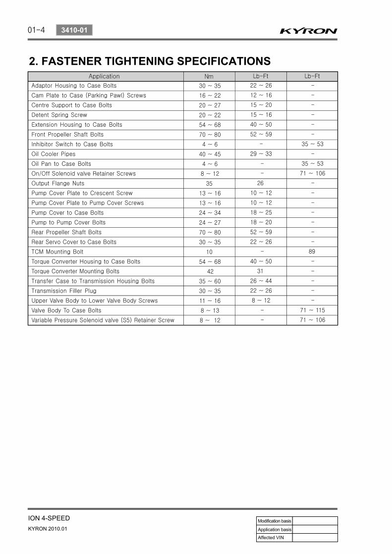
2. FASTENER TIGHTENING SPECIFICATIONS
01-5
ION 4-SPEEDKYRON 2010.01
3410-01
OVERVIEW AND OPERATION PROCESS1. DESCRIPTION AND OPERATION OF AUTOMATIC
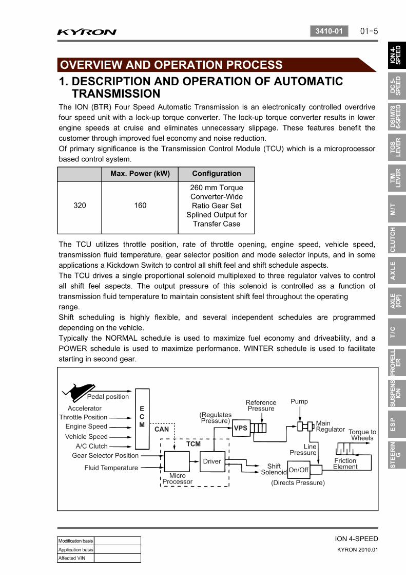
TRANSMISSIONThe ION (BTR) Four Speed Automatic Transmission is an electronically controlled overdrive four speed unit with a lock-up torque converter. The lock-up torque converter results in lower engine speeds at cruise and eliminates unnecessary slippage. These features benefit the customer through improved fuel economy and noise reduction.Of primary significance is the Transmission Control Module (TCU) which is a microprocessor based control system.
Max. Power (kW) Configuration
320 160
260 mm TorqueConverter-WideRatio Gear Set
Splined Output forTransfer Case
The TCU utilizes throttle position, rate of throttle opening, engine speed, vehicle speed, transmission fluid temperature, gear selector position and mode selector inputs, and in some applications a Kickdown Switch to control all shift feel and shift schedule aspects.The TCU drives a single proportional solenoid multiplexed to three regulator valves to control all shift feel aspects. The output pressure of this solenoid is controlled as a function of transmission fluid temperature to maintain consistent shift feel throughout the operatingrange.Shift scheduling is highly flexible, and several independent schedules are programmed depending on the vehicle.Typically the NORMAL schedule is used to maximize fuel economy and driveability, and a POWER schedule is used to maximize performance. WINTER schedule is used to facilitate starting in second gear.

01-6
KYRON 2010.01
3410-01
ION 4-SPEED
2. APPEARANCE1) 4WD Automatic Transmission
2) 2WD Automatic Transmission
Torque converter Oil cooler return
Servo
Inhibiter switchAdapter housing
Oil cooler outlet

01-7
ION 4-SPEEDKYRON 2010.01
3410-01
3. SHIFT PATTERN DIAGRAM1) Normal Mode
WINTER mode has same shift pattern with NORMAL mode except 2nd gear drive-off.-
2) Power Mode
01-8
KYRON 2010.01
3410-01
ION 4-SPEED
4. OPERATORS INTERFACESThere are three operator interfaces as the following
Gear Shift Control LeverDriving Mode SelectorIndicator Light
---
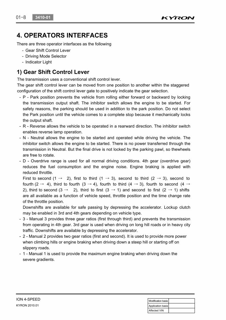
1) Gear Shift Control LeverThe transmission uses a conventional shift control lever.The gear shift control lever can be moved from one position to another within the staggered configuration of the shift control lever gate to positively indicate the gear selection.
P - Park position prevents the vehicle from rolling either forward or backward by locking the transmission output shaft. The inhibitor switch allows the engine to be started. For safety reasons, the parking should be used in addition to the park position. Do not select the Park position until the vehicle comes to a complete stop because it mechanically locks the output shaft.R - Reverse allows the vehicle to be operated in a rearward direction. The inhibitor switch enables reverse lamp operation.N - Neutral allows the engine to be started and operated while driving the vehicle. The inhibitor switch allows the engine to be started. There is no power transferred through the transmission in Neutral. But the final drive is not locked by the parking pawl, so thewheels are free to rotate.D - Overdrive range is used for all normal driving conditions. 4th gear (overdrive gear) reduces the fuel consumption and the engine noise. Engine braking is applied with reduced throttle.First to second (1 → 2), first to third (1 → 3), second to third (2 → 3), second to fourth (2 → 4), third to fourth (3 → 4), fourth to third (4 → 3), fourth to second (4 →
2), third to second (3 → 2), third to first (3 → 1) and second to first (2 → 1) shifts are all available as a function of vehicle speed, throttle position and the time change rate of the throttle position.Downshifts are available for safe passing by depressing the accelerator. Lockup clutch may be enabled in 3rd and 4th gears depending on vehicle type.3 - Manual 3 provides three gear ratios (first through third) and prevents the transmission from operating in 4th gear. 3rd gear is used when driving on long hill roads or in heavy city traffic. Downshifts are available by depressing the accelerator.2 - Manual 2 provides two gear ratios (first and second). It is used to provide more power when climbing hills or engine braking when driving down a steep hill or starting off on slippery roads.1 - Manual 1 is used to provide the maximum engine braking when driving down the severe gradients.
-
-
-
-
-
-
-
01-9
ION 4-SPEEDKYRON 2010.01
3410-01
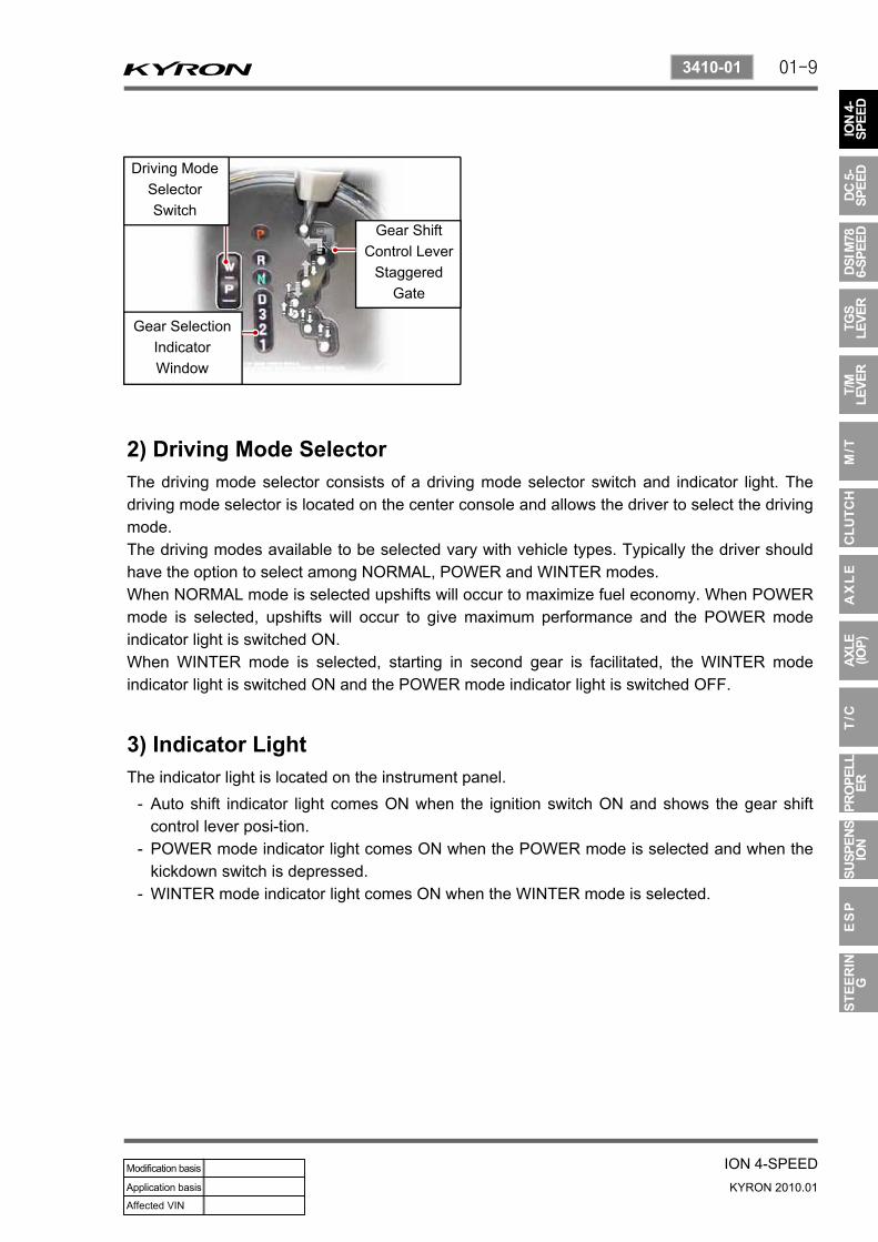
2) Driving Mode SelectorThe driving mode selector consists of a driving mode selector switch and indicator light. The driving mode selector is located on the center console and allows the driver to select the driving mode.The driving modes available to be selected vary with vehicle types. Typically the driver should have the option to select among NORMAL, POWER and WINTER modes.When NORMAL mode is selected upshifts will occur to maximize fuel economy. When POWERmode is selected, upshifts will occur to give maximum performance and the POWER mode indicator light is switched ON.When WINTER mode is selected, starting in second gear is facilitated, the WINTER mode indicator light is switched ON and the POWER mode indicator light is switched OFF.
3) Indicator LightThe indicator light is located on the instrument panel.
Auto shift indicator light comes ON when the ignition switch ON and shows the gear shift control lever posi-tion.POWER mode indicator light comes ON when the POWER mode is selected and when the kickdown switch is depressed.WINTER mode indicator light comes ON when the WINTER mode is selected.
-
-
-
Driving ModeSelectorSwitch
Gear ShiftControl Lever
Staggered Gate
Gear SelectionIndicatorWindow

01-10
KYRON 2010.01
3410-01
ION 4-SPEED
5. CONTROL SYSTEMSBTRA M74 4WD automatic transmission consists of two control systems. One is the electronic control system that monitors vehicle parameters and adjusts the transmission performance. Another is the hydraulic control system that implements the commands of the electronic control system commands.
6. ELECTRONIC CONTROL SYSTEMThe electronic control system comprises of sensors, a TCU and seven solenoids. The TCUreads the inputs and activates the outputs according to values stored in Read Only Memory(ROM).The TCU controls the hydraulic control system. This control is via the hydraulic valve body, which contains seven electromagnetic solenoids. Six of the seven solenoids are used to control the line pressure, operate the shift valves and the torque converter lock-up clutch, and to turn ON and OFF the two regulator valves that control the shift feel.The seventh solenoid is the proportional or Variable Pressure Solenoid (VPS) which works with the two regulator valves to control shift feel.
1) Transmission Control Module (TCU)The TCU is an in-vehicle micro-processor based transmission management system. It is mounted under the driver's side front seat in the vehicle cabin.
Processing logic circuits which include a central microprocessor controller and a back-up memory system.Input circuits.Output circuits which control external devices such as the Variable Pressure Solenoid (VPS) driver, On/ Off solenoid drivers, a diagnostics output and the driving mode indicator light.
-
--
The TCU contains :

01-11
ION 4-SPEEDKYRON 2010.01
3410-01
Shift schedule and calibration information is stored in an Erasable Programmable Read OnlyMemory (EPROM).Throttle input calibration constants and the diagnostics information are stored in Electrically Erasable Programmable Read Only Memory (EEPROM) that retains the memory even when power to the TCU is disconnected.TCU continuously monitors the input values and uses these, via the shift schedule, to determine the required gear state. At the same time it monitors, via the solenoid outputs, the current gear state, whenever the input conditions change such that the required gear state is different to the current gear state, the TCU initiates a gear shift to bring the two states back into line.Once the TCU has determined the type of gearshift required the TCU accesses the shift logic, estimates the engine torque output, adjusts the variable pressure solenoid ramp pressure then executes the shift.The TCU continuously monitors every input and output circuit for short or open circuits and operating range.When a failure or abnormal operation is detected the TCU records the condition code in the diagnostics memory and implements a Limp Home Mode (LHM).The actual limp home mode used depends upon the failure detected with the object to maintain maximum driveability without damaging the transmission. In general input failures are handled by providing a default value.Output failures, which are capable of damaging the transmission, result in full limp mode giving only third or fourth gear and reverse. For further details of limp modes and memory retention refer to the Diagnostic Trouble Code Diagnosis Section.The TCU is designed to operate at ambient temperatures between - 40 and 85°C (- 40 and 185°F). It is also protected against electrical noise and voltage spikes, however all the usual precautions should be observed, for example when arc welding or jump starting.
2) Processing Logic

01-12
KYRON 2010.01
3410-01
ION 4-SPEED
3) TCU InputsTo function correctly, the TCU requires engine speed, vehicle speed, transmission fluid temperature, throttle position, gear position and Kickdown Switch inputs to determine the variable pressure solenoid current ramp and on/off solenoid states. This ensures the correct gear selection and shift feel for all driving conditions.
The inputs required by the TCU are as follows :
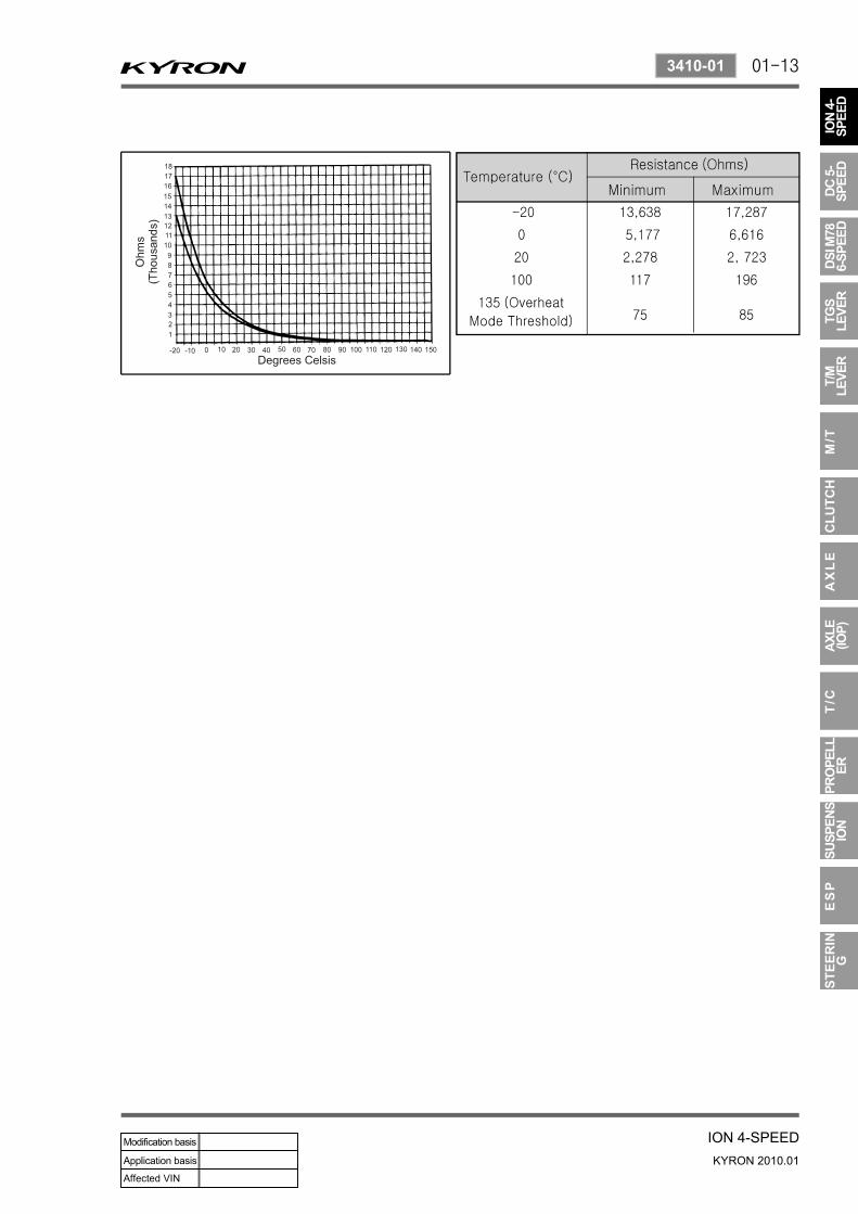
Engine Speed The engine speed signal is derived from the Controller Area Network (CAN) via Engine Control Module (ECM).Vehicle Speed The vehicle speed sensor, which is located in the transfer case, sends the output shaft speed signal to the Engine Control Module (ECM). The information is then transferred to the TCU via the CAN.Transmission Fluid Temperature The transmission fluid temperature sensor is a thermistor located in the solenoid wiring loom within the valve body of the transmission. This sensor is a typical Negative Temperature Coefficient (NTC) resistor with low temperatures producing a high resistance and high temperatures producing a low resistance.If the transmission fluid temperature exceeds 135°C (275°F), the TCU will impose converter
lock-up at lower vehicle speeds and in some vehicles flashes the mode indicator light. This results in maximum oil flow through the external oil cooler and eliminates slippage in thetorque converter. Both these actions combine to reduce the oil temperature in the transmission.
-
-
-
01-13
ION 4-SPEEDKYRON 2010.01
3410-01

01-14
KYRON 2010.01
3410-01
ION 4-SPEED
Pin No. Codes and colors in Solenoid Loom▶
Pin No. Wire Color Connects to
1 Red Solenoid 1
2 Blue Solenoid 2
3 Yellow Solenoid 3
4 Orange Solenoid 4
5 Green Solenoid 5
6 Violet Solenoid 6
7 Brown Solenoid 7
8 Green Solenoid 5
9 White Temperature Sensor
10 White Temperature Sensor
4) Gear Position SensorThe gear position sensor is incorporated in the inhibitor switch mounted on the side of the transmission case.The gear position sensor is a multi-function switch providing three functions:
Inhibit starting of the vehicle when the shift lever is in a position other than Park or NeutralIlluminate the reverse lamps when Reverse is selectedIndicate to the TCU which lever position has been selected by way of a varying resistance.
-
-
-

01-15
ION 4-SPEEDKYRON 2010.01
3410-01
Readings for Resistance / Shift Lever Positions
Shift Lever Position Resistance (kΩ)
Manual 1 1 ~ 1.4
Manual 2 21.8 ~ 2.2
Manual 3 3 3 ~ 3.4
Drive 4.5 ~ 4.9
Neutral 6.8 ~ 7.2
Reverse 10.8 ~ 11.2
Park 18.6 ~ 19
5) Diagnostic InputsThe diagnostic control input or K-line is used to initiatethe outputting of diagnostic data from the TCU to a diagnostic test instrument. This input may also be used to clear the stored fault history data from the TCU's retentive memory. Connection to the diagnostic input of the TCU is via a connector included in the vehicle's wiring harness or computer interface.
6) Battery Voltage Monitoring InputThe battery voltage monitoring input is connected to the positive side of the battery. This signal is taken from the main supply to the TCU.If the battery voltage at the TCU falls below 11.3 V, the transmission will adopt a low voltage mode of operating in which shifts into first gear are inhibited. All other shifts are allowed but may not occur because of the reduced voltage. This condition normally occurs only when the battery is in poor condition.If the battery voltage is greater than 16.5 V, the transmission will adopt limp home mode and all solenoids are turned OFF.When system voltage recovers, the TCU will resume normal operation after a 30 seconds delay period.
7) TCU OutputsThe outputs from the TCU are supplied to the components described below :
SolenoidsMode Indicator Light
--

01-16
KYRON 2010.01
3410-01
ION 4-SPEED
8) SolenoidsThe TCU controls seven solenoids. Solenoids 1 to 6 (S1 to S6) are mounted in the valve body, while Solenoid 7 (S7) is mounted in the pump cover.
Solenoid 1 and 2: S1 and S2 are normally open ON/ OFF solenoids that set the selected gear. These solenoids determine static gear position by operating the shift valves. Note that S1 and S2 solenoids also send signal pressure to allow or prohibit rear band engagement.Solenoid 3 and 4: S3 and S4 are normally open ON/ OFF solenoids that combine to control shift quality and sequencing. S3 switches the clutch regulator valve OFF or ON. S4 switches the front band regulator valve OFF or ON. S5 also provides the signal pressure for the converter clutch regulator valve.Solenoid 5: S5 is a variable pressure solenoid that ramps the pressure during gear changes. This solenoid provides the signal pressure to the clutch and band regulator, thereby controlling the shift pressures.S5 also provides the signal pressure for the converter clutch regulator valve.Solenoid 6: S6 is a normally open ON/OFF solenoid that sets the high/low level of line pressure. Solenoid OFF gives high pressure.Solenoid 7: S7 is a normally open ON/OFF solenoid that controls the application of the converter clutch.Solenoid ON activates the clutch.
-
-
-
-
-
Solenoid Logic for Static Gear States
Gear S1 S2
1st ON ON
2nd OFF ON
3rd OFF OFF
4th ON OFF
Reverse OFF OFF
Neutral OFF OFF
Park OFF OFF

01-17
ION 4-SPEEDKYRON 2010.01
3410-01
Solenoid Operation during Gearshifts▶

01-18
KYRON 2010.01
3410-01
ION 4-SPEED
Solenoid valve symbols (ON/OFF solenoids)▶
The solenoid symbol shown adjacent to each solenoid on the hydraulic system schematics indicates the state of the oil flow through the solenoid valve with the power ON or OFF.
Normally open (NO) solenoid▶
POWER ON: Line 500 port is closed. The output port is open to exhaust at the solenoid valve.POWER OFF: The exhaust port is closed. The output port is open to line 500.
Variable pressure solenoid multiplexing system▶
Friction element shifting pressures are controlled by the Variable Pressure Solenoid (VPS).Line pressure is completely independent of shift pressure and is a function of throttle position, gear state and engine speed.S5 is a proportional or variable pressure solenoid that provides the signal pressure to the clutch and band regulator valves thereby controlling shift pressures.VPS pressure is multiplexed to the clutch regulator valve, the band regulator valve and the converter clutch regulator valve during automatic gearshifts.A variable pressure solenoid produces a hydraulic pressure inversely proportional to the current applied. During a gearshift the TCU applies a progressively increasing or decreasing (ramped) current to the solenoid. Current applied will vary between a minimum oaf 200 mA and a maximum of 1000 mA. Increasing current decreases output (S5) pressure. Decreasing current increases output (S5) pressure.Line 500 pressure, (approximately 440 to 560 kPa), is the reference pressure for the VPS, and the VPS output pressure is always below line 500 pressure.

01-19
ION 4-SPEEDKYRON 2010.01
3410-01
When the VPS is at standby, that is no gearshift is taking place, the VPS current is set to 200 mA giving maximum output pressure.Under steady state conditions the band and clutch regulator valve solenoids are switched OFF.This applies full Line 500 pressure to the plunger and because Line 500 pressure is always greater than S5 pressure it squeezes the S5 oil out between the regulator valve and the plunger. The friction elements are then fed oil pressure equal to Line 500 multiplied by the amplification ratio.When a shift is initiated the required ON/OFF solenoid is switched ON cutting the supply of Line 500 to the plunger.At the same time the VPS pressure is reduced to the ramp start value and assumes control of the regulator valve by pushing the plunger away from the valve. The VPS then carries out the required pressure ramp and the timed shift is completed by switching OFF the ON/ OFF solenoid and returning the VPS to the standby pressure.This system enables either the band or clutch or both to be electrically controlled for each gearshift.
Mode indicator light▶
Depending on the application, the mode indicator light may be used to indicate the mode that has been selected or if an overheat condition exists. The mode indicator light is usually located on the instrument cluster.
9) Communication Systems
(1) CANThe Controller Area Network (CAN) connects various control modules by using a twisted pair of wires, to share common information. This results in a reduction of sensors and wiring. TCUobtains the actual engine speed and throttle position, vehicle speed and accelerator position etc. from ECM via CAN without any additional sensors.
(2) K-LineThe K-line is typically used for obtaining diagnostic information from the TCU. A scan tool with a special interface is connected to the TCU via Data Link Connector (DLC) and all current faults, stored faults, runtime parameters are then available. The stored trouble codes can also be cleared by scan tool.The K-line can be used for vehicle coding at the manufacturer's plant or in the workshop. This allows for one TCU design to be used over different vehicle mod-els.The particular code is sent to the microprocessor via the K-line and this results in the software selecting the correct shift and VPS ramp parameters.

01-20
KYRON 2010.01
3410-01
ION 4-SPEED
7. HYDRAULIC CONTROL SYSTEMThe hydraulic controls are located in the valve body, pump body and main case.
The valve body contains the following :Manual valveThree shift valvesSequence valveSolenoid supply pressure regulator valveLine pressure control valveClutch apply feed regulator valveBand apply feed regulator valveSolenoid S1 to S6Reverse lockout valve
---------
The pump cover contains the following :
Primary regulator valve for line pressureConverter clutch regulator valveConverter clutch control valveSolenoid S7
----
The main case contains the following :B1R exhaust valve-
All upshifts are accomplished by simultaneously switching on a shift valve(s), switching VPSpressure to the band and/or clutch regulator valve, and then sending the VPS a ramped current. The shift is completed by switching the regulators OFF and at the same time causing the VPS to reach maximum pressure.All downshifts are accomplished by switching VPS pressure to the band and/or clutch regulator valve and sending a ramped current to the VPS. The shift is completed by simultaneously switching the regulators OFF, switching the shift valves and at the same time causing the VPSto return to stand-by pressure.The primary regulator valve is located in the pump cover and supplies four line pressures; high and low for forward gears, and high and low for reverse. This pressure has no effect on shift quality and merely provides static clutch capacity during steady state operation. Low pressure can be obtained by activating an ON/OFF solenoid with high line pressure being the default mode.Torque converter lock-up is initiated by toggling the converter clutch control valve with an ON/OFF solenoid.The actual apply and release of the clutch is regulated by the VPS via the converter clutch regulator valve.The solenoid supply pressure regulator valve provides reference pressure for all the solenoids.

01-21
ION 4-SPEEDKYRON 2010.01
3410-01
1) Hydraulic Control Circuit

01-22
KYRON 2010.01
3410-01
ION 4-SPEED
(1) Valve Body
2) Hydraulic Components
Manual valve▶
The manual valve is connected to the vehicle selector mechanism and controls the flow of oil to the forward and reverse circuits. The manual valve function is identical in all forward gear positions except that in the Manual 1 position an additional supply of oil is directed to the 1- 2 shift valvefor application of the rear band and the C4 overrun clutch. The manual valve directs the line pressure into the PRND fluid circuits.
1-2 shift valve▶
The 1-2 shift valve is a two position valvethat must be switched to the 2, 3 and 4 position in order to get any forward gear other than first gear. It is used for all 1-2 and 2-1 gearshifts.The switching of this valve is achieved byusing S1 and/ or S2.During a 1-2 gearshift drive oil from the manual valve passes through to the second gear circuit. During a 2-1 gearshift the band apply feed oil is allowed to exhaust via the 1-2 shift valve.The 1-2 shift valve works in conjunction with the 3-4 shift valve to disengage the C4 clutch in first gear, and engage C4 in second gear. When Manual 1 is selected the C4 clutch and rear band (B2) are engaged.
01-23
ION 4-SPEEDKYRON 2010.01
3410-01
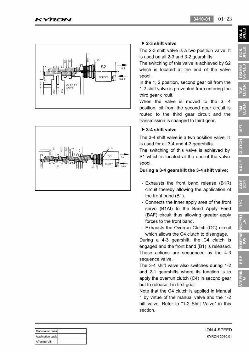
2-3 shift valve▶
The 2-3 shift valve is a two position valve. It is used on all 2-3 and 3-2 gearshifts.The switching of this valve is achieved by S2 which is located at the end of the valvespool.In the 1, 2 position, second gear oil from the 1-2 shift valve is prevented from entering the third gear circuit.When the valve is moved to the 3, 4 position, oil from the second gear circuit is routed to the third gear circuit and the transmission is changed to third gear.
3-4 shift valve▶
The 3-4 shift valve is a two position valve. It is used for all 3-4 and 4-3 gearshifts.The switching of this valve is achieved byS1 which is located at the end of the valvespool.During a 3-4 gearshift the 3-4 shift valve:
Exhausts the front band release (B1R) circuit thereby allowing the application of the front band (B1).Connects the inner apply area of the front servo (B1AI) to the Band Apply Feed (BAF) circuit thus allowing greater apply forces to the front band.Exhausts the Overrun Clutch (OC) circuit which allows the C4 clutch to disengage.
-
-
-
During a 4-3 gearshift, the C4 clutch is engaged and the front band (B1) is released. These actions are sequenced by the 4-3 sequence valve.The 3-4 shift valve also switches during 1-2 and 2-1 gearshifts where its function is to apply the overrun clutch (C4) in second gear but to release it in first gear.Note that the C4 clutch is applied in Manual 1 by virtue of the manual valve and the 1-2 hift valve. Refer to "1-2 Shift Valve" in this section.

01-24
KYRON 2010.01
3410-01
ION 4-SPEED
4-3 sequence valve▶
The 4-3 sequence valve is a two position spring loaded valve. It switches during 3-4 and 4-3 gearshifts although it performs no function during the 3-4 shift.During the 4-3 shift the 4-3 sequence valvedelays the connection of the Clutch Apply Feed (CAF) circuit to the B1R circuit until the B1R circuit has been fully pressurized by using the third gear circuit. This prevents objectionable engine flare on completion of the 4-3 gearshift.
Solenoid supply pressure regulator valve
▶
The solenoid supply pressure regulator valvesupplies a constant pressure to all solenoids (S1 to S7). Line pressure is used as the feeding oil to this regulator and the output is termed line 500.
Line pressure control valve▶
Line pressure is controlled by S6, which acts as the line pressure control valve.When S6 pressure is applied to the end of the Primary Regulator Valve (PRV), it is opposed by spring force and causes LOW line pressure for light throttle application and cruising.Heavy throttle application causes the normally open S6 to open (switch Off) thus closing line 500 and opening S6 to exhaust. Removal of S6 pressure from the PRVresults in HIGH line pressure.

01-25
ION 4-SPEEDKYRON 2010.01
3410-01
Clutch apply feed regulator valve▶
The clutch apply feed regulator valve is a fixed ratio (2.25:1) valve. This valveprovides a regulated pressure to the C1 clutch and controls the change rate of the clutch state to give the desired shift quality.Third gear oil supplied to the valve is regulated to provide an output pressure, Clutch Apply Feed (CAF) pressure, of 2.25 times the S5 signal pressure when S3 is ON. When S3 is OFF, the output pressure is 2.25 times the line 500 pressure.
Band apply feed regulator valve▶
The band apply feed regulator valve is a fixed ratio (1.4:1) valve. It provides a regulated pressure to the front servo, and controls the change rate of the front band (B1) state to give the desired shift quality.Second gear oil supplied to the valve is regulated to provide an output pressure, Band Apply Feed (BAF) pressure, of 1.4 times the S5 signal pressure when S4 is ON.When S4 is OFF the output pressure is 1.4 times the line 500 pressure.
01-26
KYRON 2010.01
3410-01
ION 4-SPEED
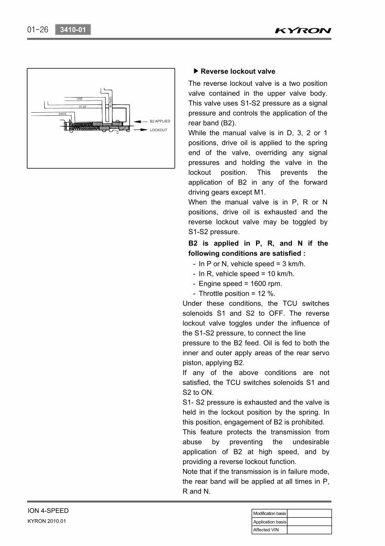
Reverse lockout valve▶
The reverse lockout valve is a two position valve contained in the upper valve body. This valve uses S1-S2 pressure as a signal pressure and controls the application of the rear band (B2).While the manual valve is in D, 3, 2 or 1 positions, drive oil is applied to the spring end of the valve, overriding any signal pressures and holding the valve in the lockout position. This prevents the application of B2 in any of the forward driving gears except M1.When the manual valve is in P, R or Npositions, drive oil is exhausted and the reverse lockout valve may be toggled byS1-S2 pressure.B2 is applied in P, R, and N if the following conditions are satisfied :
In P or N, vehicle speed = 3 km/h.In R, vehicle speed = 10 km/h.Engine speed = 1600 rpm.Throttle position = 12 %.
----
Under these conditions, the TCU switches solenoids S1 and S2 to OFF. The reverse lockout valve toggles under the influence of the S1-S2 pressure, to connect the linepressure to the B2 feed. Oil is fed to both the inner and outer apply areas of the rear servo piston, applying B2.If any of the above conditions are not satisfied, the TCU switches solenoids S1 and S2 to ON.S1- S2 pressure is exhausted and the valve is held in the lockout position by the spring. In this position, engagement of B2 is prohibited.This feature protects the transmission from abuse by preventing the undesirable application of B2 at high speed, and byproviding a reverse lockout function.Note that if the transmission is in failure mode, the rear band will be applied at all times in P, R and N.

01-27
ION 4-SPEEDKYRON 2010.01
3410-01
(2) Pump cover
Primary regulator valve▶
The Primary Regulator Valve (PRV)regulates the transmission line pressure (or pump output pressure). This valve gives either high or low line pressure depending on whether S6 is switched OFF or ON.When S6 is switched ON, S6 pressure is applied to the PRV moving it against spring pressure and opening the line pressure circuit to the pump suction port resulting in reduced line pressure.Low line pressure is used during light throttle applications and cruising. Heavy throttle will cause S6 to switch OFF and thereby cause high line pressure.This stepped line pressure control has no detrimental effect on shift feel because all shifting pressures are controlled by separate band and clutch regulator valves, and the output of S5.When reverse gear is selected, both the low and high line pressure values are boosted to guard against slippage.This is achieved by applying reverse oil line pressure to the PRV to assist the spring load. The other end of the valve contains ports for line pressure feedback and S6 pressure.The PRV also regulates the supply of oil to the converter via the converter feed port. The cascade effect of the PRV ensures the first priority of the valve is to maintain line pressure at very low engine speeds. When the engine speed increases and the pump supplies an excess of oil the PRV moves to uncover the converter feed port thereby pressurizing the converter. If there is an excess of oil for the transmission's needs then the PRV moves further to allow oil to return to the suction port.
01-28
KYRON 2010.01
3410-01
ION 4-SPEED
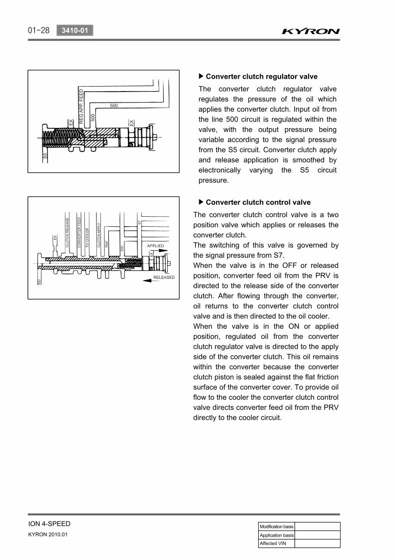
Converter clutch regulator valve▶
The converter clutch regulator valveregulates the pressure of the oil which applies the converter clutch. Input oil from the line 500 circuit is regulated within the valve, with the output pressure being variable according to the signal pressure from the S5 circuit. Converter clutch apply and release application is smoothed byelectronically varying the S5 circuit pressure.
Converter clutch control valve▶
The converter clutch control valve is a two position valve which applies or releases the converter clutch.The switching of this valve is governed bythe signal pressure from S7.When the valve is in the OFF or released position, converter feed oil from the PRV is directed to the release side of the converter clutch. After flowing through the converter, oil returns to the converter clutch control valve and is then directed to the oil cooler.When the valve is in the ON or applied position, regulated oil from the converter clutch regulator valve is directed to the apply side of the converter clutch. This oil remains within the converter because the converter clutch piston is sealed against the flat friction surface of the converter cover. To provide oil flow to the cooler the converter clutch control valve directs converter feed oil from the PRVdirectly to the cooler circuit.

01-29
ION 4-SPEEDKYRON 2010.01
3410-01
B1R exhaust valve▶
The B1R exhaust valve is a two position spring loaded valve located in the transmission case directly adjacent to the front servo. It permits the servo release oil to be rapidly exhausted into the transmission case during application of the front band (B1). This prevents the needto force the oil back from the front servo through the valvebody and through the 3-4 shift valve. The spring positions the valve to prevent oil entering the release area of the servo until the B1R circuit oil pressure reaches approximately 100 kPa.
01-30
KYRON 2010.01
3410-01
ION 4-SPEED
(3) Power train system
The Power Train System consists of :A torque converter with single face lock-up clutchFour multi-plate clutch assembliesTwo brake bandsTwo one-way clutchesPlanetary gear setParking mechanism
------
A conventional six pinion Ravigneaux compound planetary gear set is used with overdrive (fourth gear) being obtained by driving the carrier.The cross-sectional arrangement is very modular in nature.Four main sub-assemblies are installed within the case to complete the build.
Gear set-sprag-centre supportC1 -C2 -C3 -C4 clutch sub-assemblyPump assemblyValve body assembly
----
These subassemblies are :
One, or a combination of selective washers are used between the input shaft flange and the number 4 bearing to control the transmission end float. This arrangement allows for extensive subassembly testing and simplistic final assembly during production.A general description of the operation of the Power Train System is detailed below.First gear is engaged by applying the C2 clutch and locking the 1-2 One Way Clutch (1-2 OWC). The 1-2 shift is accomplished by applying the B1 band and overrunning the 1-2 OWC.The 2-3 shift is accomplished by applying the C1 clutch and releasing the B1 band. The 3-4 shift is accomplished by re-applying the B1 band and overrunning the 3-4 OWC. Reverse gear is engaged by applying the C3 clutch and the B2 band.The C4 clutch is applied in the Manual 1, 2 and 3 ranges to provide engine braking. In addition, the C4 clutch is also applied in the Drive range for second and third gears to eliminate objectionable freewheel coasting.The B2 band is also applied in the Manual 1 range to accomplish the low-overrun shift.Both the front and rear servos are dual area designs to allow accurate friction element matching without the need for secondary regulator valves. All the friction elements have been designed to provide low shift energies and high static capacities when used with the new low static co-efficient transmission fluids. Non-asbestos friction materials are used throughout.

01-31
ION 4-SPEEDKYRON 2010.01
3410-01

01-32
KYRON 2010.01
3410-01
ION 4-SPEED
Torque converter▶
The torque converter consists of a turbine, stator pump, impeller and a lock-up damper and piston assembly. As in conventional torque converters, the impeller is attached tothe converter cover, the turbine is splined to the input shaft and the stator is mounted on the pump housing via a one way clutch (sprag).The addition of the damper and piston assembly en-ables the torque converter to lock-up under favorable conditions.Lock-up is only permitted to occur in third and fourth gears under specified throttle and vehicle speed conditions.Lock-up is achieved by applying hydraulic pressure to the damper and piston assembly which couples the turbine to the converter cover, locking-up the converter and eliminating unwanted slippage. Whenever lock-up occurs, improved fuel consumption is achieved. Torsional damper springs are provided in the damper and piston assembly to absorb any engine torque fluctuations during lock-up.

01-33
ION 4-SPEEDKYRON 2010.01
3410-01
There are four clutch packs. All clutch packs are composed of multiple steel and friction plates.C1 CLUTCH: When applied, this clutch pack allows the input shaft to drive the planet carrier. This occurs in third and fourth gears.C2 CLUTCH: When applied this clutch pack allows the input shaft to drive the forward sun gear via the 3-4 OWC.This occurs in all forward gears.C3 CLUTCH: When applied this clutch pack allows the input shaft to drive the reverse sun gear. This only occurs in reverse gear.C4 CLUTCH: When applied this clutch provides engine braking on overrun. This occurs in Manual 1, 2 and 3 and also Drive2 and Drive 3 to prevent objectionable free wheel coasting.
Clutch packs▶
Bands▶
The transmission utilizes two bands, the B1 band (sometimes known as the 2-4 band), and the B2 band (sometimes known as the low-reverse band).The B1 band is a flexible band which is engaged by the front servo piston. B1 is activated in second and fourth gear. When activated B1 prevents the reverse sun gear from rotating by holding the C3 clutch assembly stationary. In second gear only the outer area of the apply piston is utilized. In fourth gear both areas are utilized for greater clamping force.

01-34
KYRON 2010.01
3410-01
ION 4-SPEED
One way clutches▶
The transmission uses two OWCs, the 1-2 OWC and the 3-4 OWC. (Note that a third OWC is located in the torque converter, also known as a sprag.)The 1-2 OWC is located between the planetary carrier assembly and the center support. This allows the carrierto rotate around the center support in one direction only. The one way clutch is engaged only in Drive 1.This 3-4 OWC is located between the C4 and the C2 clutch assemblies. This allows the C2 clutch to drive the forward sun gear in first, second and third gears but unlocks in fourth gear and during overrun.The B2 band is a solid band which is engaged by the rear servo piston. B2 is activated in Park, Reverse, Neutral andManual 1. When activated B2 prevents the planet carrier assembly from rotating. In Manual 1 only the inner area of the apply piston is utilized. In Park, Reverse and Neutral, both areas are utilized for greater clamping force.
Planetary gear set▶
The planetary gear set used in the transmission is a conventional six pinion Ravigneaux compound gear set.

01-35
ION 4-SPEEDKYRON 2010.01
3410-01
Parking mechanism▶
8. POWER FLOWSThe power flows for the various transmission selections are listed below :
Power Flow - Neutral and ParkPower Flow - ReversePower Flow - Manual 1Power Flow - Drive 1Power Flow - Drive 2Power Flow - Drive 3Power Flow - Drive 3 Lock UpPower Flow - Drive 4 (Overdrive)Power Flow - Drive 4 Lock Up
---------
The following table details the engaged elements versus the gear selected for all transmission selections.
When Park is selected the manual lever extends the park rod rearwards to engage the parking pawl. The pawl will engage the external teeth on the ring gear thus locking the output shaft to the transmission case. When Park is not selected a return spring holds the parking pawl clear of the output shaft, preventing accidental engagement of Park.
01-36
KYRON 2010.01
3410-01
ION 4-SPEED
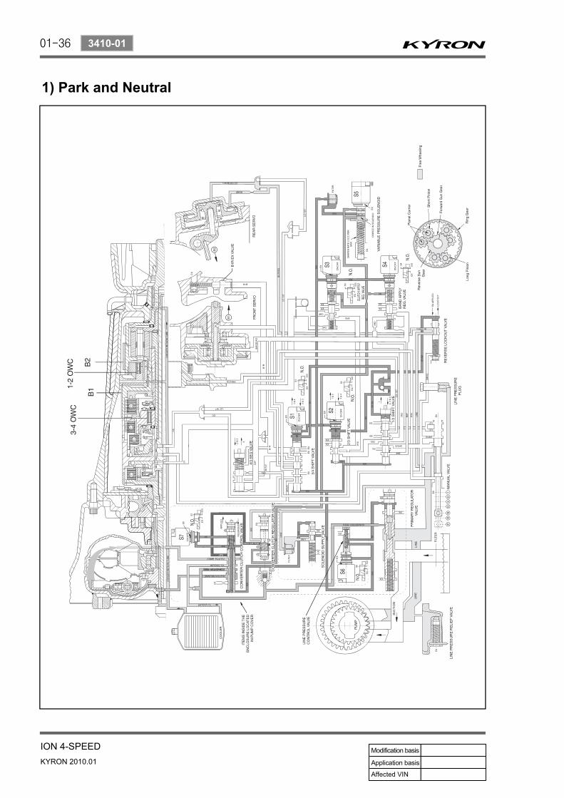
1) Park and Neutral

01-37
ION 4-SPEEDKYRON 2010.01
3410-01
(1) Power flow - Park and neutral In Park and Neutral, there is no drive to the planetary gear set. The rear band is applied to eliminate 'clunk' on engagement of the reverse gear, and to improve the low range engagement for 4WD applications. No other clutches or bands are applied.In Park the transmission is mechanically locked by engaging a case mounted pawl with teeth on the output shaft ring gear.
(2) ControlTo maintain this arrangement in the steady state solenoids and valves are activated as follows:
Solenoids S1 and S2 are switched OFF.Line (pump) pressure is applied to the Primary Regulator Valve (PRV) and to the solenoid supply pressure regulator valve.The converter, oil cooler, and lubrication circuits are charged from the primary regulator valve.The line 500 circuit is charged by the solenoid supply pressure regulator valve.The S5 circuit is charged by the variable pressure solenoid (S5).Line pressure is prevented from entering the drive circuit by the manual valve.The B1 circuit and all clutch circuits are open to exhaust.
--
-
----

01-38
KYRON 2010.01
3410-01
ION 4-SPEED
2) Reverse
01-39
ION 4-SPEEDKYRON 2010.01
3410-01
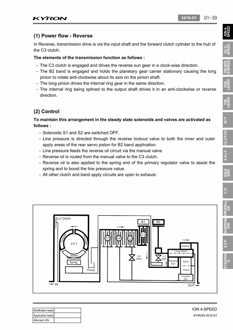
(1) Power flow - ReverseIn Reverse, transmission drive is via the input shaft and the forward clutch cylinder to the hub of the C3 clutch.
(2) ControlTo maintain this arrangement in the steady state solenoids and valves are activated as follows :
Solenoids S1 and S2 are switched OFF.Line pressure is directed through the reverse lockout valve to both the inner and outer apply areas of the rear servo piston for B2 band application.Line pressure feeds the reverse oil circuit via the manual valve.Reverse oil is routed from the manual valve to the C3 clutch.Reverse oil is also applied to the spring end of the primary regulator valve to assist the spring and to boost the line pressure value.All other clutch and band apply circuits are open to exhaust.
--
---
-
The elements of the transmission function as follows :
The C3 clutch is engaged and drives the reverse sun gear in a clock-wise direction.The B2 band is engaged and holds the planetary gear carrier stationary causing the long pinion to rotate anti-clockwise about its axis on the pinion shaft.The long pinion drives the internal ring gear in the same direction.The internal ring being splined to the output shaft drives it in an anti-clockwise or reverse direction.
--
--

01-40
KYRON 2010.01
3410-01
ION 4-SPEED
3) Manual 1

01-41
ION 4-SPEEDKYRON 2010.01
3410-01
(1) Power flow - Manual 1
(2) ControlTo maintain this arrangement in the steady state solenoids and valves are activated as follows :
Solenoids S1 and S2 are switched ON.The 1-2, 2-3, and 3-4 shift valves are held in their first gear positions by line 500 pressure.Drive (line pressure) oil from the manual valve engages the C2 clutch.Lo-1st (line pressure) oil is routed through the 1-2 shift valve to the C4 clutch, and to the inner apply area of the rear servo piston for B2 band application.
----
In Manual 1, transmission drive is via the input shaft to the forward clutch cylinder. The elements of the transmission function as follows;
The C2 clutch is engaged to drive the forward sun gear, via the 3-4 OWC.The B2 band is engaged to hold the planetary gear carrier stationary.The forward sun gear drives the short pinion anticlockwise.The short pinion drives the long pinion clockwise.The long pinion rotating about its axis drives the internal ring gear and the output shaft in a clockwise or forward direction.The C4 clutch provides engine braking through the 3-4 OWC on overrun.
-----
-

01-42
KYRON 2010.01
3410-01
ION 4-SPEED
4) Drive 1

01-43
ION 4-SPEEDKYRON 2010.01
3410-01
(1) Power flow - Drive 1
(2) ControlTo maintain this arrangement in the steady state solenoids and valves are activated as follows :
Solenoids S1 and S2 are switched ON.The 1-2, 2-3, and 3-4 shift valves are held in their first gear positions by line 500 pressure.Drive (line pressure) oil from the manual valve engagesthe C2 clutch.
---
In Drive 1, transmission drive is via the input shaft to the forward clutch cylinder. The elements of the transmission function as follows :
The C2 clutch is engaged to drive the forward sun gear via the 3-4 OWC.The forward sun gear drives the short pinion anticlockwise.The short pinion drives the long pinion clockwise.The 1-2 OWC prevents the planetary gear carrier from rotating under reaction force and the long pinion rotates on its axis driving the internal ring gear and output shaft in a clockwise or forward direction.There is no engine braking on overrun.
----
-
01-44
KYRON 2010.01
3410-01
ION 4-SPEED
5) Drive 2 and Manual 2

01-45
ION 4-SPEEDKYRON 2010.01
3410-01
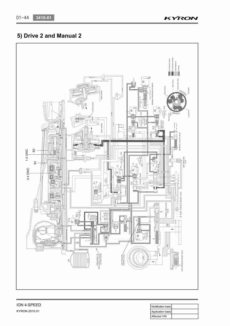
(1) Power flow - Drive 2 and manual 2
(2) ControlTo maintain this arrangement in the steady state solenoids and valves are activated as follows :
Solenoids S1 and S2 are switched ON.The 1-2, 2-3, and 3-4 shift valves are held in their first gear positions by line 500 pressure.Drive (line pressure) oil from the manual valve engagesthe C2 clutch.
---
In Drive 2 and Manual 2, transmission drive is via the input shaft and forward clutch cylinder. The elements of the transmission function as follows :
The C2 clutch is engaged to drive the forward sun gear via the 3-4 OWC.The forward sun gear drives the short pinion anticlockwise.The short pinion drives the long pinion clockwise.The 1-2 OWC prevents the planetary gear carrier from rotating under reaction force and the long pinion rotates on its axis driving the internal ring gear and output shaft in a clockwise or forward direction.There is no engine braking on overrun.
----
-

01-46
KYRON 2010.01
3410-01
ION 4-SPEED
6) Drive 3 and Manual 3

01-47
ION 4-SPEEDKYRON 2010.01
3410-01
(1) Power flow - Drive 3 and manual 3
(2) ControlTo maintain this arrangement in the steady state solenoids and valves are activated as follows:
Solenoid S1 is switched OFF. S2 is switched OFF.With S1 and S2 switched OFF, the 2-3 and 3-4 shift valves are held in the third gear position by line 500 pressure.The 1-2 shift valve is held in the third gear position by S1-S2 oil pressure.2nd oil (line pressure) from the 1-2 shift valve is directed to the band apply feed regulator valve and to the 2-3 shift valve.The band apply feed regulator valve supplies 2nd oil (regulated to line pressure multiplied by the valvera-tio) to the Band Apply Feed (BAF) circuit. Band apply feed oil is directed to
--
--
-
-
In Drive 2 and Manual 2, transmission drive is via the input shaft and forward clutch cylinder. The elements of the transmission function as follows :
The C2 clutch is engaged to drive the forward sun gear.The C1 clutch is engaged to drive the planet carrier.The short pinion drives the long pinion clockwise.The forward sun gear and the planet carrier are driven clockwise at the same speed therefore there is no relative motion between the sun gear and the pinions.The ring gear and output shaft are driven in a clockwise or forward direction at input shaft speed.The C4 clutch is applied to bypass the 3-4 OWC and provide engine braking on overrun.
----
-
-
The outer apply area of the front servoThe 1-2 shift valve to provide an exhaust port when the transmission is shifted to first gearThe 3-4 shift valve for use when the transmission is shifted into fourth gear
·
·
·
2nd oil at the 2-3 shift valve is directed to the 3rd oil circuit.3rd oil from the 2-3 shift valve is directed to the clutch apply regulator valve, and to the 4-3 sequence valve.The clutch apply regulator valve supplies oil (regulated to line 500 pressure multiplied bythe valve ratio) to the Clutch Apply Feed (CAF) circuit.
--
-
The C1clutchThe 4-3 sequence valve
·
·
The CAF oil is directed to :
At the 4-3 sequence valve the CAF oil becomes Band 1 Release Feed (B1R-F) oil, and is directed through the 3-4 shift valve to the spring end of the 4-3 sequence valve, and to the release side of the front servo piston to hold band 1 OFF.Drive (line pressure) is routed through the 3-4 shift valve to apply the C4 clutch.
-
-

01-48
KYRON 2010.01
3410-01
ION 4-SPEED
ELEMENTS ENGAGED
Gear State C1 C1 C1 C1 B1 B1 1-2OWC
3-4OWC
LUCLUTCH
Drive 3 and Manual 3
x x - x - - - x -

01-49
ION 4-SPEEDKYRON 2010.01
3410-01
7) Drive 3 Lock Up and Manual 3 Lock Up

01-50
KYRON 2010.01
3410-01
ION 4-SPEED
(1) Power flow - Drive 3 lock up and manual 3 lock up
(2) Control
In Drive 3 Lock Up and Manual 3 Lock Up, transmission drive is the same as for Drive 3 but with the application of the converter lock up clutch to provide positive no-slip converter drive.
Control for Drive 3 Lock Up and Manual 3 Lock Up is the same as for Drive 3 with the addition of the converter clutch circuit activated by solenoid S7.
When S7 is switched ON, S7 feed oil to the converter clutch control valve is switched OFF and allowed to exhaust through the S7 solenoid. This allows the valve to move to the clutch engage position.Regulated apply feed oil, drive oil at the converter clutch regulator valve, is directed by the converter clutch control valve to the engage side of the converter clutch.Converter clutch release oil is exhausted at the converter clutch control valve.Converter feed oil is re-routed by the converter clutch control valve directly to the oil cooler and lubrication circuit.
-
-
--
ELEMENTS ENGAGED
Gear State C1 C1 C1 C1 B1 B1 1-2OWC
3-4OWC
LUCLUTCH
Drive 3 Lock Up and Manual 3
Lock Upx x - x - - - x x

01-51
ION 4-SPEEDKYRON 2010.01
3410-01
8) Drive 4 (Overdrive)

01-52
KYRON 2010.01
3410-01
ION 4-SPEED
(1) Power flow - Drive 4 (Overdrive)
(2) ControlTo maintain this arrangement in the steady state solenoids and valves are activated as follows :
Solenoid S1 is switched ON. S2 is switched OFF.With S1 switched ON, the 3-4 shift valve is held in the fourth gear position by line 500 pressure on the small end of the valve.With S2 switched OFF, the 2-3 shift valve is held in the fourth gear position by line 500 pressure on the large end of the valve.The 1-2 shift valve is held in the fourth gear position by S2 oil pressure.2nd oil (line pressure) from the 1-2 shift valve is directed to the band apply feed regulator valve, and to the 2-3 shift valve.The band apply feed regulator valve supplies 2nd oil (regulated to line pressure multiplied by the valve ra-tio) to the Band Apply Feed (BAF) circuit.Band apply feed oil is directed to
--
-
--
-
-
The elements of the transmission function as follows :
The C1 clutch is applied to drive the planet carrier clockwise.The B1 band is applied to hold the reverse sun gear stationary.As the planet carrier tuns, the long pinion walks around the stationary reverse sun gear and rotates around its axis driving the internal ring gear and output shaft in a clockwise or forward direction at a speed faster than the input shaft i.e. in overdrive ratio.The forward sun gear is also driven faster than the input shaft and overruns the 3-4 OWC.The C2 clutch is engaged to reduce the speed differential across the 3-4 OWC.
---
--
the outer apply area of the front servothe inner apply area of the front servo piston via the 3-4 shift valvethe 1-2 shift valve to provide an exhaust port when the transmission is shifted to first gear
·
·
·
2nd oil at the 2-3 shift valve is directed to the 3rd oil circuit.3rd oil from the 2-3 shift valve is directed to the clutch apply regulator valve, and to the 4-3 sequence valve.The clutch apply regulator valve supplies oil (regulated to line 500 pressure multiplied bythe valve ratio) to the Clutch Apply Feed (CAF) circuit.The CAF oil is directed to
--
-
-The C1clutchThe 4-3 sequence valve
·
·
Drive oil (line pressure) from the manual valve engages the C2 clutch.-
In Drive 4 (Overdrive), transmission drive is via the input shaft to the forward clutch cylinder.

01-53
ION 4-SPEEDKYRON 2010.01
3410-01
ELEMENTS ENGAGED
Gear State C1 C1 C1 C1 B1 B1 1-2OWC
3-4OWC
LUCLUTCH
Drive 4 Overdrive x x - - x - - - -

01-54
KYRON 2010.01
3410-01
ION 4-SPEED
9) Drive 4 Lock Up

01-55
ION 4-SPEEDKYRON 2010.01
3410-01
(1) Power flow - Drive 4 lock up
(2) Control
In Drive 4 Lock Up, transmission drive is the same as for Drive 4 but with the application of the converter lock up clutch to provide positive no-slip converter drive.
To maintain this arrangement in the steady state solenoids and valves are activated as follows :
When S7 is switched ON, S7 feed oil to the converter clutch control valve is switched OFF and allowed to exhaust through the S7 solenoid. This allows the valve to move to the clutch engage position.Regulated apply feed oil, drived from drive oil at the converter clutch regulator valve, is directed by the converter clutch control valve to the engage side of the converter clutch.Converter clutch release oil is exhausted at the converter clutch control valve.Converter feed oil is re-routed by the converter clutch control valve directly to the oil cooler and lubrication circuit.
-
-
--
ELEMENTS ENGAGED
Gear State C1 C1 C1 C1 B1 B1 1-2OWC
3-4OWC
LUCLUTCH
Drive 4 Overdrive x x - - x - - - x