Embed Size (px)
Citation preview

1
Invitation of Expression of Interest through e-tendering for Empanelment of Manufacturers/ System Integrators for Rooftop
Grid Connected SPV Power Plants of capacity 1kWp to
500kWp
PART-I Submitted by: Name and address of bidder
PUNJAB ENERGY DEVELOPMENT AGENCY SOLAR PASSIVE COMPLEX Plot no. 1&2 Sector 33-D
CHANDIGARH 160 022, INDIA TELEPHONES: (91) 0172 - 2663382, 2667007 FAX : (91) 0172 – 2662865
Website: http://peda.gov.in

2
Sr. No.
CONTENTS
Subject Page No.
1 Expression of Interest. 3
2. Detailed Notice Inviting Tender. 4
3. Tender Notice 5
4. Critical Information 6
5. Eligibility Criteria and other terms & conditions. 7-9
6. General Technical Specifications. 10-22
7. Annexure 23
8. Annex-A:- Service Support Details. 24
9. Annex-B:- Performa of warranty certificate-cum-Comprehensive maintenance
contract with purchaser/consumer by empanelled agencies after successful
commissioning of project.
25
10. Annex-C: Turn Over Record form. 26
11. Annex-D: Certificate of acceptance from the bidder 27
3
PUNJAB ENERGY DEVELOPMENT AGENCY SOLAR PASSIVE COMPLEX Plot no. 1&2 Sector 33-D
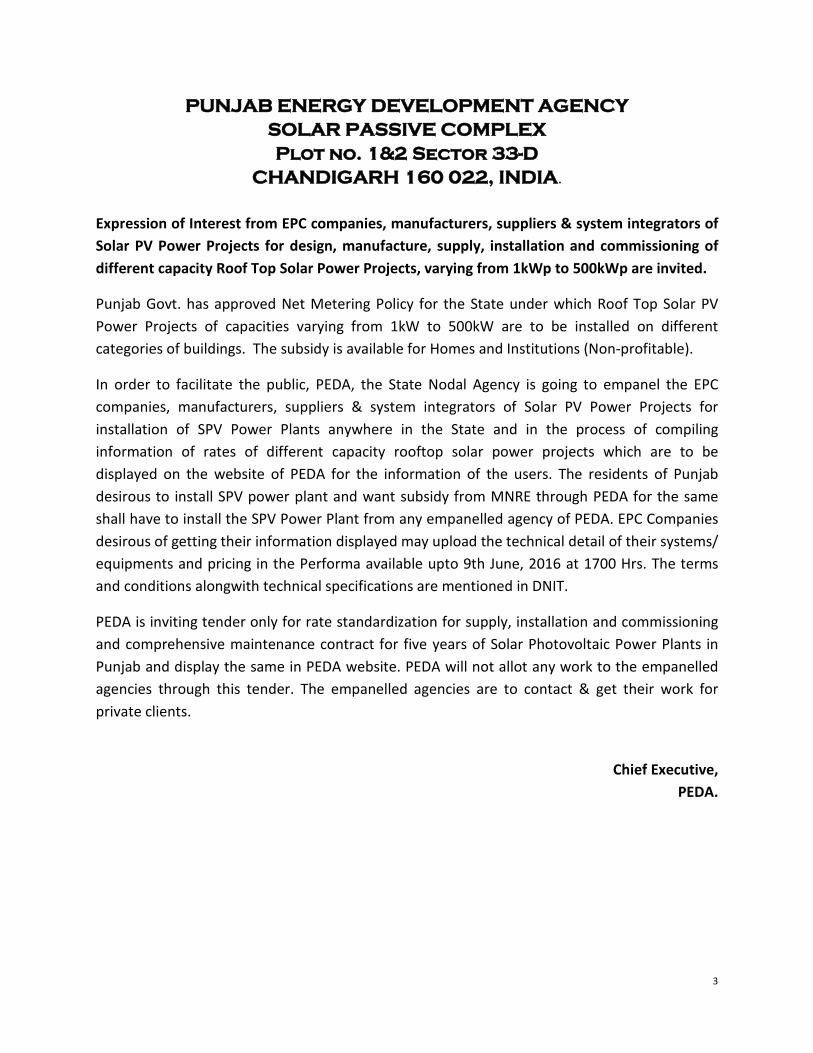
CHANDIGARH 160 022, INDIA. Expression of Interest from EPC companies, manufacturers, suppliers & system integrators of Solar PV Power Projects for design, manufacture, supply, installation and commissioning of different capacity Roof Top Solar Power Projects, varying from 1kWp to 500kWp are invited.
Punjab Govt. has approved Net Metering Policy for the State under which Roof Top Solar PV Power Projects of capacities varying from 1kW to 500kW are to be installed on different categories of buildings. The subsidy is available for Homes and Institutions (Non-profitable).
In order to facilitate the public, PEDA, the State Nodal Agency is going to empanel the EPC companies, manufacturers, suppliers & system integrators of Solar PV Power Projects for installation of SPV Power Plants anywhere in the State and in the process of compiling information of rates of different capacity rooftop solar power projects which are to be displayed on the website of PEDA for the information of the users. The residents of Punjab desirous to install SPV power plant and want subsidy from MNRE through PEDA for the same shall have to install the SPV Power Plant from any empanelled agency of PEDA. EPC Companies desirous of getting their information displayed may upload the technical detail of their systems/ equipments and pricing in the Performa available upto 9th June, 2016 at 1700 Hrs. The terms and conditions alongwith technical specifications are mentioned in DNIT.
PEDA is inviting tender only for rate standardization for supply, installation and commissioning and comprehensive maintenance contract for five years of Solar Photovoltaic Power Plants in Punjab and display the same in PEDA website. PEDA will not allot any work to the empanelled agencies through this tender. The empanelled agencies are to contact & get their work for private clients.
Chief Executive,
PEDA.

4
PEDA invites offers for rate standardization for supply, installation and commissioning and comprehensive maintenance contract for five years of Solar Photovoltaic Power Plants (SPVPP) in Punjab through e-tendering to be uploaded on the website of Punjab Govt.
DETAILED NOTICE INVITING TENDER
www.etender.punjabgovt.gov.in as per following details.
Sr. No.
Category of systems Minimum financial turn over during any one of last
three years
Minimum Capacity of single system or cumulative systems installed during last three years
(1) (2) (3) i 1 kWp to 20 kWp Rs. 15.00 Lac. 5 kWp or 20 kWp Cumulative. ii 21 kWp to 50 kWp Rs. 50.00 Lac. 20 kWp or 50 kWp Cumulative. iii 51 kWp to 100 kWp Rs. 500.00 Lac. 30 kWp or 100 kWp Cumulative. iv 101 kWp to 500 kWp Rs. 200.00 Lac. 50 kWp or 500 kWp Cumulative.
The tenderers, who have satisfactorily completed SPV projects of installation & commissioning of Solar Photo Voltaic power plants with at least one single SPVPP or cumulative of capacity as mentioned in the column No. (3) of the above table, anywhere in country along with minimum financial turn over in any one of last three years as mentioned in Colum no (2). The tenderer should have its office cum Service Centre in Punjab/ Chandigarh with qualified staff. Tenderer can quote for any category, as per their eligibility.
The tender document can be downloaded/uploaded by the bidders from the website of Punjab Govt. at www.etender.punjabgovt.gov.in from 20.5.2016 to 9.5.2016. The tender document should be uploaded in the prescribed manner up to 17.00 Hrs on 9.5.2016 & the technical bid of tenders shall be opened on 10.5.2016 at 3.30PM. The date of opening of price bid of the tenderers who qualify in the technical bid to be intimated. A pre-bid meeting shall be organized on 21.5.2016 at 03.00 PM at this office. The tender document is also available at PEDA's web site www.peda.gov.in.
PEDA reserves all rights to accept/reject any or all tenders in full/part without assigning any reasons.
Chief Executive,
PEDA.

5
GO SOLAR PUNJAB
EXPRESSION OF INTEREST FROM EPC COMPANIES
ROOFTOP SOLAR-PUNJAB
E-tender notice no.
PEDA/2016-17/04
Expression of Interest from EPC companies, manufacturers, suppliers & system integrators of Solar PV Power Projects for design, manufacture, supply, installation and commissioning of different capacity Roof Top Solar Power Projects, varying from 1kWp to 500kWp are invited.
EMD (Rs. In Lacs) 5.00
Date of start of downloading E-tender document 20.05.2016
Pre-Bid Meeting 31.05.2016 at 3:00 PM
Last Date & time for submission of E-bids 09.06.2016 upto 5:00 PM
Date & time of opening of Techno-commercial E-bids 10.06.2016 at 3:00 PM
1. Eligibility criteria and other terms & conditions for the works are given in the Tender Document which can be downloaded from www.etender.punjabgovt.gov.in or www.peda.gov.in.
2. Bidders shall have to get themselves registered with etender.punjabgovt.gov.in
3. PEDA reserve the right to accept or reject any or all the tenders without assigning any reason thereof.
and get user ID and Password. Class-3 Digital Signature, mandatory to participate in the e-tendering process. For any clarification/difficulty regarding e-tendering process flow, please contact PEDA at 0172-2663328, 2663382, 85588-70510 or 0172-3934667, 92572-09340, 80546-28821.
CHIEF EXECUTIVE
Punjab Energy Development Agency, Solar Passive Complex, Sec-33-D, Chandigarh

6
Availability of Bid Document
CRITICAL INFORMATION
www. etender.punjabgovt.gov.in
Last date & time for receipt of bids 9.06.2016 upto 5:00 PM
Date and Time for opening of Technical bids
10.06.2016 at 3:00 PM
Earnest Money Deposit 5 Lacs (Rs. Five Lacs)
Tender Document Fee Non refundable Tender Document fee Rs.5,000/- through IPG/ RTGS Mode only to be paid at the time of downloading of bid document.
E-Processing Fee Non-refundable e-processing fee Rs. 2,290/- through IPG/ RTGS mode.
Submission of E-tender, Bid document fee and EMD/ Bank Guarantee (Bid document fee & E-Processing fee deposited through IPG/RTGS mode only)
Through E-Tender
www.
etender.punjabgovt.gov.in
Place of opening of E-bids Conference Room, Punjab Energy Development Agency, Solar Passive Complex, Plot No -1 &2, Sector -33D, Chandigarh
Contact person for any queries Jaspal Singh, Senior Manager (SPV)
Punjab Energy Development Agency,
Solar Passive Complex, Plot No -1 &2,
Sector -33D, Chandigarh
Ph No.0172-2663328, 2667007
Fax: 0172-2662865
Email:- [email protected]
7
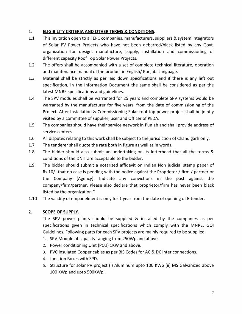
1. ELIGIBILITY CRITERIA AND OTHER TERMS & CONDITIONS1.1 This invitation open to all EPC companies, manufacturers, suppliers & system integrators
of Solar PV Power Projects who have not been debarred/black listed by any Govt. organization for design, manufacture, supply, installation and commissioning of different capacity Roof Top Solar Power Projects.
.
1.2 The offers shall be accompanied with a set of complete technical literature, operation and maintenance manual of the product in English/ Punjabi Language.
1.3 Material shall be strictly as per laid down specifications and if there is any left out specification, in the Information Document the same shall be considered as per the latest MNRE specifications and guidelines.
1.4 The SPV modules shall be warranted for 25 years and complete SPV systems would be warranted by the manufacturer for five years, from the date of commissioning of the Project. After Installation & Commissioning Solar roof top power project shall be jointly visited by a committee of supplier, user and Officer of PEDA.
1.5 The companies should have their service network in Punjab and shall provide address of service centers.
1.6 All disputes relating to this work shall be subject to the jurisdiction of Chandigarh only. 1.7 The tenderer shall quote the rate both in figure as well as in words. 1.8 The bidder should also submit an undertaking on its letterhead that all the terms &
conditions of the DNIT are acceptable to the bidder. 1.9 The bidder should submit a notarized affidavit on Indian Non judicial stamp paper of
Rs.10/- that no case is pending with the police against the Proprietor / firm / partner or the Company (Agency). Indicate any convictions in the past against the company/firm/partner. Please also declare that proprietor/firm has never been black listed by the organization.”
1.10 The validity of empanelment is only for 1 year from the date of opening of E-tender.
2. SCOPE OF SUPPLYThe SPV power plants should be supplied & installed by the companies as per specifications given in technical specifications which comply with the MNRE, GOI Guidelines. Following parts for each SPV projects are mainly required to be supplied.
.
1. SPV Module of capacity ranging from 250Wp and above. 2. Power conditioning Unit (PCU) 1KW and above. 3. PVC insulated Copper cables as per BIS Codes for AC & DC inter connections. 4. Junction Boxes with SPD. 5. Structure for solar PV project (i) Aluminum upto 100 KWp (ii) MS Galvanized above
100 KWp and upto 500KWp,.

8
6. ACDB with SPD and MCB/MCCB, Uni-directional solar meter and necessary protection as per CED rules and safety regulations.
7. Lightening arrestor. 8. Danger board. 9. Earthing as per BIS/ISI standards required for the SPV Power Plant. 10. Remote monitoring system from 10kWp and onwards. 11. O&M manual and warranty card in English/Punjabi Language. 12. The process and expenditure of meter testing and electrical inspection. 13. Any other part as per site requirement.
3.
i. The Solar power projects shall be warranted for five years after the date of commissioning of the project for replacement in case of any manufacturing, operation failure, non performance as per design standards.
WARRANTY
ii. The PV module(s) shall be warranted for a minimum period of 25 years from the date of commissioning of the project. The PV modules must be warranted for their output peak watt capacity, which should not be less than 90% at the end of Ten (10) years and 80% at the end of Twenty five (25) years.
iii. The Warranty Card to be supplied with the system must contain the details of the system. The bidder will have to be furnishing a warranty certificate of the systems on a required stamp paper for the same.
4.
a) Visit to the site on call basis to provide maintenance services within two days of lodging of complaint.
Comprehensive Maintenance Contract during Warranty period of five years.
b) Corrective & remedial maintenance services to set right the malfunction of the SPV-projects include supply and replacement of all damaged parts/ components including electronics/ charge controller, Inter connected cables/ parts and fuse etc. with new parts.
5.
• An Operation, Instruction and Maintenance Manual in English/Punjabi languages should be provided with the Solar PV projects. The following minimum details must be provided in the Manual.
OPERATION & MAINTENANCE MANUAL
• Basic principles of Photovoltaic. • A small write-up (with a block diagram) on the Solar PV project - its components,
PV module, inverter, junction boxes and expected performance shall be provided.

9
• Type, Model number, Voltage & capacity of inverter, used in the system. • The make, model number, country of origin and technical characteristics of all
the component are required to be provided. • Clear instructions on regular maintenance and trouble shooting of the Solar PV
Projects. • DO's and DONT's. • Name, address and Mobile No. of the contact person for repair and
maintenance, in case of non-functionality of the SPV Projects.

10
1.
GENERAL TECHNICAL SPECIFICATIONS.
Each solar PV plant array capacity should not be less than the capacity of the same SPV Plant capacity and it should comprise of solar Mono crystalline modules of minimum 250 watts. The Photovoltaic modules must be tested & approved by one of the IEC authorized test centers , Test Certificates can be from any of the NABL / BIS accredited testing / calibration laborites the module type must be qualified as per IEC 61215( Second Edition). In addition PV modules must qualify to IEC 61730 Part I to II for safety qualification testing. SPV module conversion efficiency should not be less than 16.0% under STC.
SOLAR PHOTOVOLTAIC MODULES.
The module shall have warranty of 25 years with degradation of power generated not exceeding 20% of the minimum rated power over the 25 years period and not more than 10% after 10 years period. The Bidder will have to furnish a CORPORATE GURANTEE on a required stamp paper for the same. IDENTIFICATION AND TRACEBILITY. Each PV module used in any solar power project must use a RF Identification Tag (RFID), which must contain the following Information: i. Name of the manufacturer of PV Module ii. Name of the manufacturer of solar cells iii. Month and year of the manufacturer (separately for solar cells and modules. iv. Country of Origin (separately for solar cells and modules v. I-V Curve for the module vi. Peak wattage , Im , Vm and FF for the module vii. Unique Serial No and Model No of the Module viii. Date and year of obtaining IEC PV module qualification certificate. ix. Name of the test lab issuing IEC certificate
2.
The supplier shall specify installation details of the PV modules and the support structures with appropriate diagrams and drawings. Such details shall include, but not limited to the following:
SPV PANEL ARRAY STRUCTURES
• Determination of true south at the site; • Array tilt angle to the horizontal, with permitted tolerance; • Details with drawings for fixing the modules; • Details with drawings of fixing the junction/terminal boxes; • Interconnection details inside the junction/terminal boxes; • Structure installation details and drawings;
11
• Electrical grounding (earthing); • Inter-panel/Inter-row distances with allowed tolerances; and • Safety precautions to be taken The array structure shall support SPV modules at a given orientation to absorb and transfer the mechanical loads to the roof properly. The portion of array structure if any lying within the column shall be of GI of superior quality and Alluminium as per scope of supply. All nuts and bolts shall be of very good quality stainless steel. Detailed design and Drawing of the module mounting structures shall have to be submitted to PEDA for acceptance before execution of work. Strict care should be taken during execution to avoid any damage to the roof surface of the buildings and to ensure no leakage should occur.
i. Wherever required, Suitable number of PV panel structures shall be provided. Structures shall be of flat-plate design and can be with combination of I, C and L or any sections as per structure design requirement.
ii. Structural material shall be corrosion resistant and electrolytically compatible with the materials used in the module frame, its fasteners, nuts and bolts. Galvanizing should meet ASTM A-123 hot dipped galvanizing or equivalent which provides at least spraying thickness of 70 microns as per IS5909, if steel is used.
iii. Structures with adequate strength and in accordance with relevant BIS standards shall be used with proof that the design of the structure can withstand a wind speed upto 170KM per Hour.
iv. Structures shall be supplied complete with all members to be compatible for allowing easy installation at the rooftop site.
v. Each structure should have angle of inclination as per the site conditions to take maximum insulation.
vi. The base plate and vertical section of the structure should be minimum of 3 mm thickness.
vii. Each panel frame structure be so fabricated as to be fixed on the rooftop column/wall structures. The structures shall be designed for simple mechanical and electrical installation. There shall be no requirement of welding or complex machinery at the installation site. If prior civil work or support platform is absolutely essential to install the structures, the supplier shall clearly and unambiguously communicate such requirements along with their specifications in the bid. Detailed engineering drawings and instructions for such prior civil work shall be carried out prior to the supply of Goods. All nuts and bolts shall be of very good quality stainless steel except foundation bolts which will be of MS (GI Coated).
viii. The structure should be non penetrating and low height. The entire structure should be connected to each other in a grid form so as to sustain the wind speed upto 170KM/Hr.

12
ix. If, possible, 4 Ft. offset from boundary of rooftop from all sides should be kept while installing structure for modules.
x. No damage in any way should be caused to the building rooftops while installation of SPV Power Plant. If any damage done it will wholly be the responsibility of the bidder and cost shall be recovered from the bidder
3. POWER CONDITIONING UNIT (STRING INVERTORS)The power conditioning units of each different capacity SPV Power Plants totaling should not be less than the each SPV Power Plant capacity and it should be provided to convert DC power produced by SPV modules, in to AC power. A multi function power conditioning system combining the functionality of a grid interactive solar inverter with a highly efficient conversion unit having following Technical Specification:
.
Type : Self commuted, current regulated, high frequency IGBT based with Trench Gate Structure
Output voltage : Single Phase, 230V, AC (1kWp to upto 10kWp) and 3 phase, 415V, AC (more than10kWp to upto 500kWp) (+12.5%, - 20%V, AC)
Frequency : 50 Hz ±1 Hz Continuous rating : Not less than system capacity individually DC input Operating range : 500 V to 5000V nominal Total Harmonic Distortion : less than 3 % Operating temperature Range : 0 to 55 deg C Housing cabinet : PCU to be housed in suitable cabinet with
minimum IP65 standard Inverter efficiency : >95 % at full load. Power Control : MPPT
The bidder shall use the original parts in case of any fault in the PCU/Inverter during the CMC period of 5 years. In case the original part/parts are not available with the manufacturer of the PCU/Inverter (Based on certificate from the manufacturer), the bidder shall use the new parts of other standard brands available in the market or will use the repaired parts. Other important Features/Protections required in the PCU.
• Authentic tracking of the solar arrays maximum power point tracking (MPPT).

13
• Array ground fault detection. • LCD and piezoelectric keypad operator interface Menu driven • Automatic fault conditions reset for all parameters like voltage, frequency and/or
black out. • MOV and gas filled spark gap technology type surge arresters on AC and DC
terminals for over voltage surge protection from any source. • PCU should be rated to operate at 0 to 55 deg. Centigrade above ambient temp • All parameters should be accessible through an industry standard communication
link. • The PCU should go in sleep mode when there is no grid supply. • The string inverter should have display of adequate size on its front panel to show
various parameters. 3.1 Since the PCU is to be used in solar photo voltaic energy system, it should have high
operational efficiency. The idling current at no load must not exceed 2 percent of the full-load current.
3.2 A suitable Surge Protection Device separately at output (A.C. side) shall be provided for each SPV Power Plant.
3.3 The PCU output shall be 230V,AC for single phase and 415V, AC, 50 Hz for 3 phase. 3.4 The PCU shall include appropriate self protective and self diagnostic features to
protect itself and the PV array from damage in the event of PCU component failure or from parameters beyond the PCU’s safe operating range due to internal or external causes. The self-protective features shall not allow signals from the PCU front panel to cause the PCU to be operated in a manner which may be unsafe or damaging. Faults due to malfunctioning within the PCU, including commutation failure, shall be cleared by the PCU protective devices and not by the existing site utility grid service circuit breaker. The PCU shall go to shut down/standby mode, with its contacts open, under the following conditions before attempting an automatic restart after an appropriate time delay; in sufficient solar power output etc.
a) Insufficient Solar Power Input
When the power available from the PV array is insufficient to supply the losses of the PCU, the PCU shall go to a standby/shutdown mode. The PCU control shall prevent excessive cycling during rightly shut down or extended periods of insufficient solar radiation. The power conditioning units / inverters should be applicable IEC/ equivalent BIS standard for efficiency measurement and environmental testing as per standard code IEC 61683 and IEC 60068 2(6,21,27,30,75,78). The charge controller/ MPPT

14
units should qualify IEC 62093 and IEC 60068 2 (6,21,27,30,75,78). The junction boxes/ enclosures should be IP 65(for outdoor)/ IP 54 (indoor) and as per IEC 62208 specifications. The PCU’s should be tested from the MNRE approved test centres / NABL /BIS accredited testing- calibration laboratories. In case of imported power conditioning units, these should be approved by international test houses. Party must supply and upload the test report of PCU /inverter along with the tender document.
b) Utility-Grid Over or Under Frequency 3.5 The PCU shall restart after an over or under frequency shutdown when the utility
grid voltage has returned to the within limits for minimum of two minutes. 3.6 The PCU generated harmonics measures at the point of connection to the utility
services when operating at the rated power shall not exceed a total harmonic current distortion of 3 percent, a single frequency current distortion of 3 percent and single frequency voltage distortion of 1 percent, when the first through the fiftieth integer harmonics of 50 Hz are considered.
3.7 The PCU Power factor at the point of utility service connection shall be 0.95 lagging or leading when operating at above 25 percent of the rated output, but may be less than 0.95 lagging below 25 percent of the rated output.
3.8 The high voltage and power circuits of the PCU shall be separated from the low-voltage and control circuits. All conductors shall be made of standard copper.
3.9 The PCU shall withstand a high voltage test of 2000 V rms, between either the input or the output terminals and the cabinet (chassis).
3.10 Full protection against accidental open circuit and reverse polarity at the input shall be provided.
3.11 The PCU shall not produce Electromagnetic Interference (EMI) which may cause malfunctioning of electronic and electrical instruments including communication equipment, which are located within the facility in which the PCU is housed.
3.12 The PCU shall have an appropriate display on the front panel to display the instantaneous AC power output and the DC voltage, current and power input. The display shall be visible from outside the PCU enclosure. Operational status of the PCU, alarms, trouble indicators and ac and the dc disconnect switch positions shall also be communicated by appropriate messages or indicator lights on the front cover of the PCU enclosure.
3.13 ELECTRICAL SAFETY, EARTHING AND PROTECTIONa) Internal Faults: In built protection for internal faults including excess
temperature, commutation failure, overload and cooling fan failure (if fitted) is obligatory.
:

15
b) Over Voltage Protection: Over Voltage Protection against atmospheric lightning discharge to the PV array is required. Protection is to be provided against voltage fluctuations in the grid itself and internal faults in the power conditioner, operational errors and switching transients.
c) Earth fault supervision: An integrated earth fault device shall have to be provided to detect eventual earth fault on DC side and shall send message to the supervisory system.
d) Cabling practice: Cable connections must be made using PVC Cu cables, as per BIS standards. All cable connections must be made using suitable terminations for effective contact. The PVC Cu cables must be run in GL trays with covers for protection.
e) Fast acting semiconductor type current limiting fuses at the main bus-bar to protect from the grid short circuit contribution.
3.14 The PCU shall include an easily accessible emergency OFF button located at an appropriate position on the unit.
3.15 The PCU shall include ground lugs for equipment and PV array grounding. The DC circuit ground shall be a solid single point ground connection in accordance with WEC 69042.
3.16 All exposed surfaces of ferrous parts shall be thoroughly cleaned, primed, and painted or otherwise suitably protected to survive a nominal 10 years design life of the unit.
3.17 The PCU enclosure shall be weatherproof and capable of surviving climatic changes and should keep the PCU intact under all conditions. Moisture condensation and entry of rodents and insects shall be prevented in the PCU enclosure.
3.18 Components and circuit boards mounted inside the enclosures shall be clearly identified with appropriate permanent designations, which shall also serve to identify the items on the supplied drawings.
3.19 All doors, covers, panels and cable exists shall be gasketed or otherwise designed to limit the entry of dust and moisture. All doors shall be equipped with locks. All openings shall be provided with grills or screens with openings no larger than 0.95 cm.
3.20 The design and fabrication of the PCU the site temperature (0O to 70O
C), incident sunlight and the effect of ambient temperature on component life shall be considered carefully. Similar consideration shall be given to the heat sinking and thermal for blocking diodes and similar components.
16
3.21 FACTORY TESTINGa) Preparation of all controls, protective and instrumentation circuits shall be
demonstrated by direct test if feasible or by simulation operation conditions for all parameters that cannot be directly tested.
:
b) Operation of start up, disconnect and shutdown controls shall also be tested and demonstrated. Stable operation of the PCU and response to control signals shall also be tested and demonstrated.
c) Factory testing shall include measurement of phase currents, efficiencies, harmonic content and power factor.
d) A factory Test Report (FTR) shall be supplied along with the unit. The FTR shall include detailed description of all parameters tested qualified and warranted.
3.22 OPERATING MODESThe following operating modes are to be made available.
.
Night or Sleep mode: Where the inverter is almost completely turned off, with just the timer and control system still in operation, losses should not exceed 2 watts per 5 kilowatt. In case of Grid Failure, the PCU should go in sleep mode/ turned off immediately. Standby mode: Where the control system continuously monitors the output of the solar generator until pre-set value is exceeded (typically 20 watts). Operational or MPP tracking mode: The control system continuously adjust the voltage of the generator to optimize the power available. The power conditioner must automatically re-enter stand-by mode when input power reduces below the standby mode threshold. Front Panel display should provide the status of the PCU, including AC Voltage, Current, Power output & DC Current, Voltage and Power input, pf and fault Indication (if any).
3.23
As per the standard of IEEE 519, the permissible individual harmonics level shall be less than 3% (for both voltage and current harmonics) and Total Harmonics Distortion (THD) for both voltage and current harmonics of the system shall be less than 5%.
HARMONICS STANDARD
Overall conditions of service
Technical and interconnection requirements State Distribution/Supply Code State Distribution/Supply Code
Overall Grid Central Electricity Authority (Grid
Central Electricity Authority (Grid Standard)

17
Standards Standard) Regulations 2010 Regulations 2010 Equipment BIS / IEC / IEEE BIS / IEC / IEEE Meters Central Electricity authority
(Installation & operation of meters) Regulation 2006 as amended time to time
Central Electricity authority (Installation & operation of meters) Regulation 2006 as amended time to time
Safety and supply Central Electricity Authority(measures of safety and electricity supply) Regulations, 2010
Central Electricity Authority(measures of safety and electricity supply) Regulations, 2010
Harmonic IEEE 519 CEA (Technical IEEE 519 CEA (Technical Standards for
Requirements Standards for Connectivity of the
Connectivity of the Distributed Generation
Harmonic Current Distributed Generation Resources) Regulations 2013
Resources) Regulations 2013
Synchronization IEEE 519 CEA (Technical Standards for Connectivity of the Distributed Generation Resources) Regulations 2013
Photovoltaic system must be equipped with a grid frequency synchronization device. Every time the generating station is synchronized to the electricity system. It shall not cause voltage fluctuation greater than +/- 5% at point of connection.
Voltage IEEE 519 CEA (Technical Standards for Connectivity of the Distributed Generation Resources) Regulations 2013
The voltage-operating window should minimize nuisance tripping and should be under operating range of 80% to 110% of the nominal connected voltage. Beyond a clearing time of 2 second, the photovoltaic system must isolate itself from the grid.
Flicker IEEE 519 CEA (Technical Standards for Connectivity of the Distributed Generation Resources) Regulations 2013
Operation of Photovoltaic system should not cause
Frequency IEEE 519 CEA (Technical Standards for Connectivity of
When the Distribution system frequency deviates outside the

18
the Distributed Generation Resources) Regulations 2013
specified conditions (50.5 Hz on upper side and 47.5 Hz on lower side), There should be over and under frequency trip functions with a clearing time of 0.2 seconds.
DC injection IEEE 519 CEA (Technical Standards for Connectivity of the Distributed Generation Resources) Regulations 2013
Photovoltaic system should not inject DC power more than 0.5% of full rated output at the interconnection point or 1% of rated inverter output current into distribution system under any operating conditions.
Power Factor IEEE 519 CEA (Technical Standards for Connectivity of the Distributed Generation Resources) Regulations 2013
While the output of the inverter is greater than50%, a lagging power factor of greater than 0.9 should operate.
Islanding and IEEE 519 CEA (Technical The photovoltaic system in the event of fault,
Disconnection Standards for Connectivity of the Distributed Generation Resources) Regulations 2013
voltage or frequency variations must island/disconnect itself within IEC standard on stipulated period.
Overload and Overheat IEEE 519 CEA (Technical Standards for Connectivity of the Distributed Generation Resources) Regulations 2013.
The inverter should have the facility to automatically switch off in case of overload or overheating and should restart when normal conditions are restored.
Paralleling Device IEEE 519 CEA (Technical Standards for Connectivity of the Distributed Generation Resources) Regulations 2013.
Paralleling device of photovoltaic system shall be capable of withstanding 220% of the normal voltage at the interconnection point.
ENERGY METER CONFIGURATION OPTIONS. The metering system for rooftop solar system, under net-metering arrangement, shall be as under: - One Bi-directional as main meter and One No. Uni-directional as solar meter with necessary CTs as requirement. The metering system for rooftop solar system, under gross-metering arrangement, shall be as

19
under: - One Bi-directional as export meter and one No. Bi-directional as check meter with necessary CTs as requirement.
Sr. No. Meter Description Accuracy Load of Consumer Voltage 1. Single Phase 10-
60A, Class-I Up to 10kW Single Phase LT 230V.
Grid System Stability: to be examined by the Distribution Licensee.
2. 3 Phase 10-60A, whole Current
Class-I More than 10kW& up to 25kW
Three Phase LT 400 V
3. LT AC 3 Phase 4 Wires CT operated static DLMS AMR Compliant energy
meter
Class-0.5S or better
More than 25kW& up to 500kW
Three Phase LT 400 V
The Solar power generated at rooftops will be collected at one central point in the same building from where it will be fed on LT side. If required, any protection device/ adapter panel/breaker/switchgear be provided to terminate the each SPV Power Plant output on LT side by the party at its own cost. METER TESTING & ELECTRICAL CLEARANCEAll installation work should be done as rules & regulations of Indian Electricity Act. & Electricity Department, U.T., Chandigarh and JERC, solar power – grid connected ground mounted and solar rooftop and metering regulations-2015 for the State of Goa & Union Territories. The bidder/ empanelled agency shall have to take the clearance from SDO/Electrical Inspector, UT, Chandigarh as the case may be at its own cost before connecting to the Grid. The process and expenditure of meter testing and electrical inspection to be met by bidder/ empanelled agency.
:
4.
There should be a separate Surge Protection Device to be provided on D.C. and A.C. Side.
SURGE PROTECTION DEVICE (SPD)
5. 5.1 Common AC Distribution Panel Board (DPB) shall control the AC power from inverter. AC
Distribution panel (ACDP) should consist of appropriate size of MCB/MCCB with appropriate breaking capacity as incomer and suitable numbers of MCB/MCCB with appropriate size breaking capacity out going switches.
COMMON AC DISTRIBUTION PANEL BOARD (ACDPB).

20
5.2 The panel should have space for Energy Meter.
6. CABLESa. ISI marked as per given brands PVC insulated Copper Cond. Cable of various sizes as per
load requirement for connecting all the modules / arrays to Jn. Boxes and from Jn. Boxes to AJB and from AJB to inverter. Copper/ Aluminum armored Cables of appropriate size from Inverter onwards in A.C. side.
:-
b. Cabling: Cabling shall be carried out as per IE Rules. All other cabling above ground should be suitably mounted on cable trays with proper covers.
c. Wires: Only copper wires of appropriate size based on load requirements of reputed make as specified in DNIT shall have to be used. However aluminum cables can be used on A.C side of transmission. However on D.C Side, only solar D.C. Cable should be used. PVC/XLPE insulated armoured sheathed cables required for the plant will be provided by the manufacturer. All cable schedules/ layout drawings have to be got approved from the purchaser prior to installation)
d. Cables Ends: All connections are to be made through suitable cable/lug/terminals; crimped properly & with use of Cable Glands.
e. Cable Marking: All cable/wires are to be marked with proper manner by good quality ferule or by other means so that the cable can be easily identified. Cu/Al. PVC insulated armoured sheathed cables required for the plant will be provided by the manufacturer. However Cables for both D.C/A.C as per brands and specifications mentioned can be used. All cable schedules/ layout drawings have to be got approved from the purchaser prior to installation.
7. LIGHTNING PROTECTION
There shall be the required number of suitable lightning arrestors installed in the array area. Lightning protection shall be provided by the use of metal oxide arrestors and suitable earthing such that induced transients find an alternate route to earth. Protection shall meet the safety rules as per Indian Electricity Act and Electricity Department, U.T., Chandigarh.
.
8. EARTHING PROTECTION
Each array structure of the PV yard should be grounded/ Earthing properly as per IS:3043-1987. In addition the lighting arrester/masts should also be provided inside the array field. Provision should be kept for shorting and grounding of the PV array at the time of maintenance work. All metal casing/shielding of the plant should be thoroughly grounded in accordance with Indian electricity Act./IE Rules and Electricity Department, U.T., Chandigarh. Earth Resistance should be tested in presence of the representative of
:

21
Department after earthing by calibrated earth tester. PCU and ACDB should also be earthed properly.
9. COMPREHENSIVE MAINTENANCEAll the equipments (but in case of SPV Modules the guarantee period is 25years) shall be provided with comprehensive Maintenance for 5 years against unsatisfactory performance and/or break down due to defective design, workmanship of material. The equipments or components, or any part thereof, so found defective during Comprehensive Maintenance period shall be forthwith repaired or replaced free of cost to the satisfaction of the beneficiary.
:
10. JET PUMP 1/2 HP ( CROMPTON/ KIRLOSKOR):
As per site requirement, minimum 1 No. 1/2 HP BIS approved surface pumps shall be installed for each SPV Power Plant for 10kWp and above. Suitable Nos of water outlets shall be provided through B-class ISI Marked GI Pipes for cleaning of the modules.
-
11. SCOPE OF CMC OF SPV POWER PLANT FOR A PERIOD OF 5 YEAR FROM DATE OF
COMMISSIONINGa. Proper CMC of the SPV Power Plant for a period of five years after
commissioning along with supply of consumable items as and when necessary and submission of daily performance data of the power plant shall come, under the CMC contract.
:
The break down maintenance of the entire system including supply of necessary spare parts, if any, are already under the coverage of warranty clause of the specific condition for a period of 60 months from date of commissioning of power plant. The CMC schedule of the SPV power plant during the 5 years contract period shall be as detailed below.
b. The security of the power plant will rest with the supplier/agency till such time operation and maintenance of the power plant is not handed over to the purchaser/department.
c. The deputed personnel shall be qualified and well trained so that they can handle any type of operation hazard quickly and timely.
d. The deputed personnel shall be in a position to check and test all the equipment regularly, so that, preventive actions, if any, could be taken well in advance to save any equipment from damage. Any abnormal behavior of any equipment shall be brought to the notice of Engineer-in-Charge immediately for appropriate action.

22
e. Normal and preventive maintenance of the power plant such as cleaning of module surface, tightening of all electrical connections etc.
f. During CMC period of 5 years of the power plant, if there is any loss or damage of any component of the power plant due to miss management/miss handling or due to any other reasons, what-so-ever, the supplier/firm shall be responsible for immediate replacement/rectification. The damaged component may be repaired, if it is understood after examination that after repairing performance of the component shall not be degraded, otherwise the defective component shall have to be replaced by new one without any extra cost.

23
ANNEXURES (A TO D)

24
Annexure – A
SERVICE SUPPORT DETAILS
NEAREST SERVICE CENTRE Pack No.
Destination Location List of models & types of Pcs. Serviced in last
2 years
Phone no.
Telex/ Fax no.
Status of
office working days
and hours
No. of softw
are engineers
No. of hardware engineers
No.of hardw
are staff
Value of
Min. stock available at
all times
Signature and Seal of the
Manufacturer/Bidder

25
Annexure – B
(On a required stamp paper)
PERFORMA OF WARRANTY CERTIFICATE-CUM-COMPREHENSIVE MAINTENANCE CONTRACT WITH PURCHASER/CONSUMER BY EMPANELLED AGENCIES AFTER SUCCESSFUL
COMMISSIONING OF SPV POWER PLANT
Order No. Date:
We _____(Name of empanelled agency with registered address)_______ do hereby certify that
the _________(make of modules)______ SPV Modules as used for _______(Name of the
project)_____ shall have warranty of 25 years with degradation of power generated not
exceeding 20% of the minimum rated power over the 25 years period and not more than 10%
after 10 years period.(Detail lists of Solar PV Modules enclosed)
Further, We _____(Name of empanelled agency with registered address)_______ do hereby
certify that the whole system of the ____(Name of the project)______ shall have warranty and
comprehensive maintenance contract for the period of 5 years from the date of commissioning
of the project.
Further, if, we _____(Name of empanelled agency with registered address)_______ fails to
provide the 5 years warranty and comprehensive maintenance contract of whole system and 25
years warranty of SPV Modules as mentioned above, then we are liable for legal action
including blacklisting of the firm by PEDA/ Consumer/ Purchaser.
Signature _____________________
Name ___________________________
Designation with stamp _____________

26
Annexure-C
To be certified by Chartered Accountant
TURNOVER RECORD FORM
Name of Company:-
Annual turnover data for past three years
Sr. No. Year Turnover (Rs. In Lacs) Profit Loss
1 2 3 4 5
1. 2012-13
2. 2013-14
3. 2014-15
Signature with seal of the company
Signature with seal of the Chartered Accountant

27
(On the letter head of the bidder)
Annexure-D
CERTIFICATE OF ACCEPTANCE FROM THE BIDDER.
I, the bidder __________________________________ agrees / accepts to the
terms and conditions of DNIT.
Name & Seal of the Authorized
Person of the Company