Embed Size (px)
Citation preview

I N V E S T I G A T I O N OF NEW U N I V E R S A L
M E A S U R I N G M I C R O S C O P E S
E. P. A l e k s e e v a , M. G. B o g u s l a v s k i i ,
a n d T. L K a l i n i n a
UDC 531.715.001.5
New types of op t icomechanica l instruments for l inear and angular measurements have recent ly been developed and produced, including universal measuring microscopes UIM-23 and UIM-24 made by the Leningrad Opt icomechan- i ca l Association. As compared with the measurement l imits of s imilar Zeiss and the UIM-21 microscopes, those of
the UIM-24 microscope have been extended in the longitudinal direction up to 500 mm and in the transverse d i rec- tion up to 200 mm, thus making i t sui table for measuring large components with masses up to 100 kg and lengths up
to 1000 ram. An e lec t r i ca l hoist is provided for faci l i ta t ing the placing of heavy components on the microscope
stage. Instrument UIM-23 is provided with a special opt ical device for measuring holes from 0.2 to 50 mm by a con- tactless method. Its reading and sighting devices consist of opt ica l micrometers , transverse reticles, and doub le - im-
age systems.
The reading of l inear displacements and angles as wel l as sighting is made in the new microscopes on screens. The use of screens reduces eye fatigue, thus faci l i ta t ing the work of inspectors and raising its eff iciency.
In UIM-21 microscopes the mat t surface of the screen glass used for sighting in the project ion at tachments is very rough. Owing to this fact and to the absence of bright sources of light, a sufficiently sharp image cannot be ob-
tained, thus raising the instrument 's error.
The structure of the diffusing layer cannot be seen on the wax screens of the new instruments, and the lumi- nous flux is uniformly distributed over a large solid angle. Therefore, i t is possible to i l lumina te the instruments ef- fec t ive ly , so that they provide a clear image of the a r t i c le on sighting screens or graduated scales of display devices.
The sighting systems of instruments UIM-23 and UIM-24 use K - 8 - 5 5 (8V, 55W) bulbs with a concentrated in- candescent body which approaches a point source and provides a screen i l luminance up to 30 Ix for diaphragm aper- tures of not less than 5 mm. For apertures below 5 mm the i l luminance of the screen field of vision drops, thus pro-
ducing cer ta in difficulties in sighting. Therefore, the problem of l ight sources for sighting systems cannot be con- sidered solved.
The sighting (Table 1) and reading (Table 2) error of the screen were determined in testing the new intruments by comparing them with the sighting error of the UIM-21 and Zeiss instruments with monocular microscopes andwith the binocular UIM-23 a t tachment . The width of the re t ic le dashed line in instruments UIM-21, UIM-23, and UIM- 24 amounts to 5/2, and in the Zeiss instrument to 4/~. The width of lines on the reference scale amounts to 5 #.
It wi l l be seen from Tables 1 and 2 that the root -mean-square errors of sighting in the UIM-23 and Zeiss in- struments are a l i t t le lower than those of the UIM-21 and UIM-24 instruments, whereas the root -mean-square error of setting a graduation to a double - l ine re t ic le on the display screen of the UIM-23 and UIM-24 instruments is of the same order as that of the Zeiss instrument 's measuring microscope and is smal ler than the error of instrument UIM-
21. In these instruments,produced since 1965, this error does not exceed 0,1 t~, which is less than in instruments with he l i ca l microscopes.
The display systems' errors of instruments UIM-23 and UIM-24 (Table 2) are reduced by replacing the he l i ca l UIM-21 micrometer with an opt ica l one for reading hundredths and thousandths of a mi l l imeter .
The instrumen.ts' errors were determined by means of the following measurements.
1. By comparing the graduations of a 1st grade reference scale as measured on a microscope stage to their true ca l ibra ted values.
Translated from Izmer i t e l ' naya Tekhnika, No. 4, pp. 13-15, April , 1968. Original a r t ic le submit ted November 24, 1967.
443

TABLE 1. Root-Mean-Square Errors of Setting the Dashed Line of a Sighting System Reticle to a Line
of a Reference Scale Placed on the Microscope Stage
Carriage dis-
p lacement
Longitudina 1 N
Transverse
Position of carr iage
Extreme left
Middle Extreme right
Extreme rear Middle Extreme forward
Types of universal measuring microscopes
UIM-21 Zeiss UIM-23 UIM-23 UIM-23 UIM-24 No. 650035 No, 620001 No. 650035 No. 650043 No. 620003 No. 650043
Observation system
Binoc ula r Screen
0.33 0.40
0.33
0,33 0.30 0.40
Eyepiece
0.27
0.33 0.30
0.30 0.30
0.33
0,20 0.27
0,30 0,23
0.27 0.27
0,27 0.23
0.20 0.33
0.17 0,30
0.27
0,2q
0.22
0,23
0,27
0.27
0.40
0.30 0.40
0.40 0,30 0,40
TABLE 2. Root-Mean-Square Error in /~ of Setting a Graduation to the Double-Line Reticle of Dis-
play Systems
Setting graduations (mi l l imetr ic) to the
double- l ine re t ic le of tenths fractions Types of universal measuring microscopes
UIM-21 Zeiss UIM-23 No. 620001 No. 650035
No. 620003 No. 650043
with he l i ca l microscopes . . . . . ] wi '~ opt{cai ~
a) for a longitudinal movement
UIM-23 UIM-24
................... micr0rneters
With zero double- l ine re t ic le scales for tenths fractions 0.40 0,13
With double- l ine reticles of O.Smm 0.20 0.20 With double- l ine reticles of 0.9 mm 0.30 0.20
b) for a transverse movement
With a zero double- l ine re t ic le 0.33 0,13 With double- l ine reticles of 0.5 mm 0.30 0,17 With double- l ine reticles of 0.9 mm 0.30 0.20
0.27
0.20
0,10
0.13 0.10 0.30
0.10
0.10
0.10
0.10 0.10 0,10
0,17
0.10
!0.13
0,10 0.20
0,13
2. By measuring the diameters of reference cyl indr ica l smooth gauges (between centers) whose true values were determined beforehand by means of grade 4 block gauges on a horizontal optimeter . Measurements on the uni- versal microscope were made by the axia l cross section and shadow-project ion methods.
3. By comparing the measured mean diameter , profile angle, and pitch of reference thread gauges (between centers) to the true values of the diameter and pitch and of the profile angle determined with errors of ~:1.0-1.3 g and ~ 1.5-2' respectively. Measurements were made by the methods of shadow projection and axial cross section.
4. By measuring a gauge angle a = 90" whose true value was determined with an error of J~ 5%
5. By measuring the internal diameters of ring gauges and external ganges consisting of 3rd grade block gauges,
Instruments UIM-23 and UIM-24 have two sighting devices (a binocular a t tachment and a screen in the UIM- 23 instrument, and a screen and a microscope with an eyepiece in the UIM-24 instrument) and, therefore, errors have been evaluated for ei ther sighting system. Tests have shown the following.
1) The errors made in comparisons with reference scale graduations and smooth cy l indr ica l gauges are of the same order for the UIM-23, UIM-21,and the Zeiss instruments, including both sighting systems of instrument UIM-23.
444
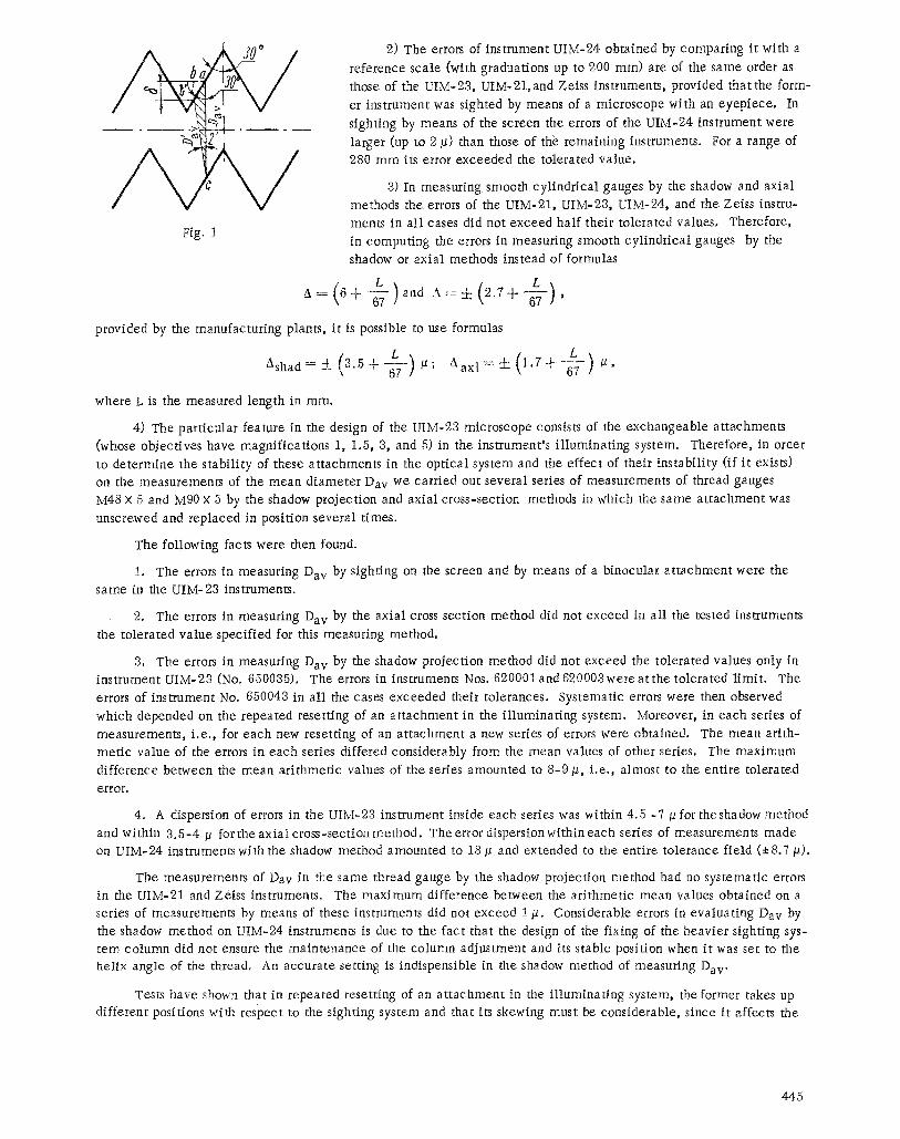
Fig, 1
2) The errors of instrument UIM-24 obtained by comparing it with a
reference scale (with graduations up to 200 ram) are of the same order as
those of the UIM-23, UIM-21,and Zeiss instruments, provided that the form-
er instrument was sighted by means of a microscope with an eyepiece. In
sighting by means of the screen the errors of the UIM-24 instrument were
larger (up to 2 #) than those of the remaining instruments. For a range of 280 mm its error exceeded the tolerated value.
3) In measuring smooth cylindrical gauges by the shadow and axial
methods the errors of the UIM-21, UIM-23, UIM-24, and the Zeiss instru-
ments in all cases did not exceed half their tolerated values. Therefore,
in computing the errors in measuring smooth cylindrical gauges by the
shadow or axial methods instead of formulas
provided by the manufacturing plants, it is possible to use formulas
ashad= (a Aaxl= +
where L is the measured length in ram.
4) The particular feature in the design of the UIM-23 microscope consists of the exchangeable attachments
(whose objectives have magnifications 1, 1.5, 3, and 5) in the instrument's i l luminating system. Therefore, in order
to determine the stability of these attachments in the optical system and the effect of their instability (if it exists) on the measurements of the mean diameter Day we carried out several series of measurements of thread gauges
M48 X 5 and M90 x 5 by the shadow projection and axial cross-section methods in which the same at tachment was
unscrewed and replaced in position several times.
The following facts were then found.
1. The errors in measuring Day by sighting on the screen and by means of a binocular at tachment were the
same in the UIM-23 instruments.
2. The errors in measuring Day by the axial cross section method did not exceed in all the tested instruments
the tolerated value specified for this measuring method.
3, The errors in measuring Day by the shadow projection method did not exceed the tolerated values only in instrument UIM-23 (No. 650035). The errors in instruments Nos. 620001and 620003wereat the tolerated limit. The
errors of instrument No. 650043 in all the cases exceeded their tolerances. Systematic errors were then observed
which depended on the repeated resetting of an at tachment in the i l luminating system. Moreover, in each series of
measurements, i .e. , for each new resetting of an at tachment a new series of errors were obtained. The mean arith- metic value of the errors in each series differed considerably from the mean values of other series. The maximum
difference between the mean arithmetic values of the series amounted to 8-9 #, i,e., almost to the entire tolerated
e r r o r ,
4, A dispersion of errors in the UIM-23 instrument inside each series was within 4.5 -7 ~ for theshadow method
and within 3.6-4/1 for the axiaI cross-section method. The error dispersion within each series of measurements made on UIM-24 instruments with the shadow method amounted to i8 / l and extended to the entire tolerance field (J:8.7/~),
The measurements of Day in the same thread gauge by the shadow projection method had no systematic errors
in the UIM-21 and Zeiss instruments. The maximum difference between the arithmetic mean values obtained on a series of measurements by means of these instruments did not exceed 1 #. Considerable errors in evaluating Day by
the shadow method on UIM-24 instruments is due to the fact that the design of the fixing of the heavier sighting sys- tem column did not ensure the maintenance of the column adjustment and its stable position when it was set to the helix angle of the thread. An accurate setting is indispensible in the shadow method of measuring Day,
Tests have shown that in repeated resetting of an at tachment in the i l luminat ing system, the former takes up different positions with respect to the sighting system and that its skewing must be considerable, since it affects the
445

measurements of Day by the shadow method. In exchanging attachments with different magnifications i t is often nec-
essary for the same reason to readjust the light source with respect to the instrument's opt ical axis,
In instruments with exchangeable at tachments which have objectives in the i l luminat ing system,considerable importance is acquired by the value of the tolerated deviation from perpendiculari ty of the axis of the sighting sys- tem's column to the l ine of measurement, since the light source is adjusted in the a t tachment with respect to the sighting system. The tolerated deviations from perpendiculari ty in the UIM-23 instruments amount to 2 ' , In manu- facturing instruments with such a large tolerance there arises a considerable systematic error in evaluating Day of threads. This is what happened in instrument No. 650045.
By examining the shaded triangle (see Fig, 1) i t is possible to determine the error 6 which is produced by t i l t - ing the sighting system through angle 2' (for a zero reading of the column scale) and results in displacing point a to
position b. Therefore, instead of the true value of Day the value of D~v is measured, since the tilt ing of the column through the helix angle of the thread deflects the position of the sighting point from line ac when the transverse car- r iage is moved from one side of the thread profile to its opposite side.
We find from the formulas that
, Davsin 30o00 , Dav~ sin 30 ~ 02' ; 6 =: Day-- Day ..
By substituting for D~v its true value D a v = 43,470 mm (for gauge M48X 5), we find that 6 = 0,044 ram, which
exceeds considerably the tolerated error of ~:8.7 g, The above computat ion indicates that the tolerated deflect ion of the sighting system from perpendiculari ty to the measurement line in the longitudinal direction must be reduced to 20%
5) The errors in measuring the profile angle of gauges M48 x 5 and M90 X 5 on microscope UIM-23 are in the range of • which is larger than the error of :~(2-2.8') obtained on the UIM-24, UIM-21, and theZeiss instru- ments, The larger error is due to a great extent to the inaccurate angle reading device used in the UIM-23 instru- ment. The device for reading fractions of a degree consists of two para l le l scales which have factors of 2' and are displaced with respect to each other by 1', The reading error of such a scale is equal to 45-60% Recently the UIM-
23 instrument has been fitted with transverse graticules which provide a reading error of 20-30", Their error did not exceed :kl .5 ' in measuring a plane angle,
The manufacturing plant does not provide any error formulas for ei ther angular quantities or the profile angle
of threads measured on UIM-23 and UIM-24 instruments, On the basis of the VNIIM (All-Union Scientific-Research Institute of Metrology) investigation,we took the error in measuring a plane angle, i .e . , :k 1.5' as the maximum mea -
surement error of angular quantities. This value can also be used for the first term of the formula for the maximum tolerated measurement error of the gauges 'profi le angle. Taking into account that the error increases with a reduc- tion of the thread pitch, this formula can be represented for the axia l cross section in the form
A a x l = : : l : ( 1 . 5 - b ' 7 - ) min. o f thea rc ,
where S is the thread pitch.
6) Errors in measuring the pi tch of thread gauges by the methods of shadow projection and axia l cross sections have not exceeded the values provided in formulas of these instruments' instructions compi led by the manufacturing plants,
The UIM-23 instrument is provided with a perf lectometer , a contactless opt ical device for measuring through holes with diameters of 0,2 to 50 mm. Testing has shown that the root-mean-square error of superposing the colored images of cross hairs in the field of vision of the screen does not depend on the measured diameter and is equal to 0,2-0.3/~, The errors in measuring internal sizes of 0.2 to 50 mm do not exceed 1-2 g,
7) Errors obtained in using a perf lec tometer in the UIM-23 set are larger than those of special instruments which are used for testing holes and are based on the same principle. This is due to the fact that the errors of the UIM-23 instrument 's sighting and reading devices and mechanica l units which control the displacement of the measured ring gauge exceed considerably the perf lectometer ' s opt ical error, which is equal to 0,1 g. Therefore, in order to reduce this error i t is advisable to produce special instruments which measure holes with a perf lec tometer and are provided with a sighting and reading system whose errors do not exceed 0.1-0.2/~.
446

CONCLUSIONS
I. The measurement errors of microscopes of the new system are at the same level as those of the UIM-21 and
the Zeiss microscopes, with the exception of the error in measuring Dav of a thread gauge by means of the shadow
method and the error in measuring the profile angle of a thread,
2. The larger error in measuring Day and the profile angle as compared with similar existing instruments is
due to the imperfections of certain units in the design,
3. The errors in measuring the diameters of smooth cylindrical gauge s by the shadow projection and axial
cross-section methods are considerably smaller than those obtained from the formulas of the manufacturing plant,
4. The manufacturing plant should indicate in the instrument's operating instructions the error in measuring a
plane angle and provide a formula for the errors in measuring profile angles of thread gauges.
5. The utilization of wax screens in the sighting and display devices has not reduced the precision of the in-
struments, but at the same time has made them more convenient in work and tends to reduce the fatigue of the tester,
thus raising the productivity of his labor.
6. The screens can be used for sighting not only in the shadow projection method, but also in the axial cross-
section method.
7. Testing of the UIM-23 and UIM-24 instruments has shown that only in measuring the mean diameter of threads by the shadow project ion method do the instrumental, technological , and adjustment deficiencies of these instruments have a most pronounced effect on the precision of their readings and the measurement error. Therefore, in drafting standards or procedure instructions for testing these instruments i t is necessary to specify requirements for measuring the Day of thread gauges by means of the shadow method.
447