Embed Size (px)
Citation preview

INVERTER MULTIAIR CONDITIONER
CONTENTS
SPECIFICATIONS . . . . . . . . . . . . . . . . . . . . . 1
OUTLINE AND DIMENSIONS . . . . . . . . . . . 2
REFRIGERANT SYSTEM DIAGRAM . . . . . 4
ERROR CONTENTS . . . . . . . . . . . . . . . . . . 9
CIRCUIT DIAGRAM . . . . . . . . . . . . . . . . . . . 5
INDOOR PCB CIRCUIT DIAGRAM . . . . . . 7
OUTDOOR PCB CIRCUIT DIAGRAM . . . . 8
DISASSEMBLY ILLUSTRATION . . . . . . . . . 10
PARTS LIST . . . . . . . . . . . . . . . . . . . . . . . . . 17
Models
Indoor unit Outdoor unit
AUY12LBAB AOY18LMAK2AUY14LBAB
CASSETTE type

COMPRESSOR
DIMENSIONS
Hermetic type, Inverter, 4 poles, Three phase, DC motor, Rotary
TNB 220 FPCM
R410A (g) 1,900
(V) 230
HI
DISCRIMINATION
(r.p.m.)
MED (r.p.m.)
LO (r.p.m.)
(r.p.m.) 780
H x W x D (mm)
H x W x D (mm) 235 x 580 x 580+70
650 x 830 x 320
FAN MOTOR
WEIGHT
730
MFA-14GTCT
670
590
12005.08.18
SPECIFICATIONS
TYPE
DISCRIMINATION
REFRIGERANT
POWER SOURCE
INDOOR UNIT
OUTDOOR UNIT
NOISE LEVEL
INDOOR UNIT
H x W x D (mm) 35 x 650 x 650GRILL
OUTDOOR UNIT
GROSS / NET (kg)
GROSS / NET (kg) 23 / 18
62 / 56
INDOOR UNIT
GROSS / NET (kg) 4.3 / 2.2GRILL
OUTDOOR UNIT
COOL & HEAT
AUY14LBABAUY12LBAB
AOY18LMAK2
TYPE
INDOOR UNIT
OUTDOOR UNIT
HI (dB)
LO
COOLING
HEATING
(dB)
(dB)
(dB)
50
42
MED (dB) 39
36
49
INDOOR UNIT
OUTDOOR UNIT
3.3
3.7
4.0
4.2
1.2 1.5
(kW)
(kW)
(V) 230
COOLING CAPACITY (MAX)
HEATING CAPACITY (MAX)
COOLING
HEATING
COOLING
HEATING
COOLING
HEATING
(Hz) 50
(A)
(kW)
(kW)
(kW)
(kW / kW)
7.5 (9.7)
8.0 (9.7)
5.5 (6.5)
6.4 (7.1)
(m3/hr)
ELECTRICAL DATA ( OUTDOOR UNIT )
ELECTRICAL DATA ( INDOOR UNIT )
1.73 (2.22)
1.84 (2.22)
3.18
3.48
550
COOLING CAPACITY
HEATING CAPACITY
MOISTURE REMOVAL
POWER SOURCE
FREQUENCY
RUNNING CURRENT
E.E.R.
AIR CIRCULATION-Hi
(MAX)
INPUT WATTS(MAX)
( /hr)
235
66
250
440
580
( 650) (Grille measurement)650
(Hanging bolt position)400
(Han
ging
bol
t pos
ition
)60
6
580
66440
600(Ceiling opening measurement)
250
60
86
Drain pipe (I.D. 32)
54
46
131
111 47
(unit : mm)
INDOOR UNIT
OUTLINE AND DIMENSIONS
20 3565
0
650
Models :AUY12LBABAUY14LBAB
22005.08.18
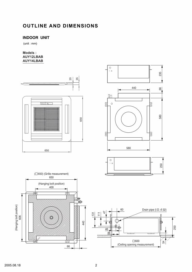
OUTDOOR UNITUnit : mm
Model : AOY18LMAK2
Air flowBottom
603
343
350830
650
12
32005.08.18

REFRIGERANT SYSTEM DIAGRAM
A Unit
B Unit
heat exchanger(Indoor)
heat exchanger(Outdoor)
3-wayvalve
2-wayvalve
accumulatorcompresser
4-way valve
COMP
electricexpansionvalve
strainer
strainerreceiver tank
EVA
EVB
HEAT
COOL
42005.08.18

INDOOR UNITS
CIRCUIT DIAGRAM
Models :AUY12LBABAUY14LBAB
52005.08.18
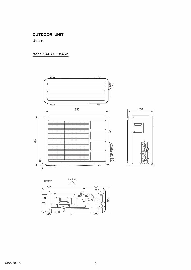
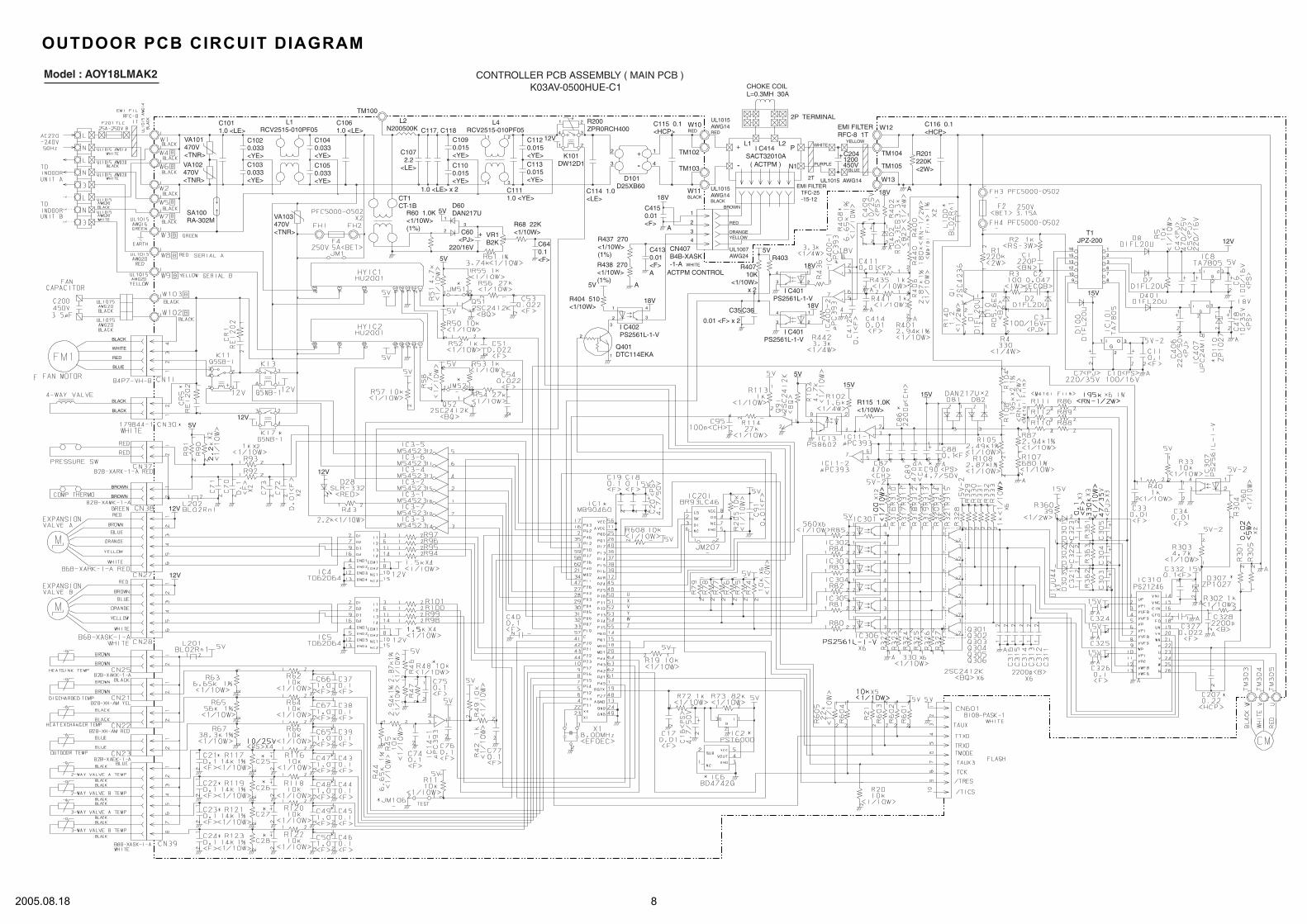
OUTDOOR UNIT
Thermistor(heat sink)
Expansionvalve coil B
Expansionvalve coil A
Fan capacitor
Fan motor
4-way valve
Compressor
Choke coil
Capacitor
PCBCN39
CN38
CN37
CN407
CN11
CN21
CN22
CN25
CN27
CN11
CN30
CN28
CN23
Compressorpressure sw
Activefiltermodule
Compressorthermal sw
Thermistor (valve)
FuseF2 T 3.15A 250V
FuseF4 T 5A 250V
Thermistor(outdoor)
Thermistor(pipe)
Thermistor(discharge)
Model : AOY18LMAK2
62005.08.18

230 V50HZ
CONTROLLER PCB ASSY ( MAIN PCB )INDOOR PCB CIRCUIT DIAGRAMAUY12LBAB : K01AL-040THSE-C1AUY14LBAB : K01AL-040WHSE-C1
72005.07.19
12V
12V
5V12V
12V
BLACK
BLACK
BROWN
BROWN
BLACK
WHITE
RED
BLUE
( ACTPM )
18V
C4150.01<F>
A
C4130.01<F>A
A
R437 270<1/10W>(1%)
R438 270<1/10W>(1%)
5V
R404 510<1/10W>
18V
I C402PS2561L-1-V
Q401DTC114EKA
2
1
3
2
1 4
3
CN407B4B-XASK-1-A WHITE
ACTPM CONTROL
4
1
2
3
BROWN
RED
ORANGEYELLOW
UL1007AWG24
TM102
TM103
W11BLACK
D101D25XB60
+
-
1
4
2
3
UL1015AWG14BLACK
+
-
I C414SACT32010A
L1 L2P
N1
UL1015AWG14RED
W10RED
2P TERMINAL
WHITE
PURPLEBLUE
YELLOW
+C2041200450V
EMI FILTERRFC-8 1T
W12
W13
18V
TM104
TM105
A
R201220K<2W>
C116 0.1<HCP>
UL1015 AWG142T
EMI FILTER TFC-25 -15-12
CHOKE COILL=0.3MH 30A
C115 0.1<HCP>
C114 1.0<LE>
R200ZPR0RCH400
1
4
2
3
1 2
C1130.015<YE>
C1120.015<YE>
12V
K101DW12D1
L4RCV2515-010PF05
1 2
34
C1090.015<YE>
C1100.015<YE>
C1111.0 <YE>
5V1
23
+C60<PJ>
220/16V
5V
C107 2.2<LE>
1.0 <LE> x 2
C117, C118
TM100
L2N200500K
C1040.033<YE>
C1050.033<YE>
C1061.0 <LE>
C1020.033<YE>C1030.033<YE>
L1RCV2515-010PF05
C1011.0 <LE>
VA101470V<TNR>
VA102470V<TNR>
SA100RA-302M VA103
470V<TNR>
R60 1.0K<1/10W>(1%)
CT1CT-1B D60
DAN217U
C640.1<F>
VR1B2K
R68 22K<1/10W>
12V T1JPZ-200
15V
12
367
8910121315
16
1
2
3I OG
C35C36
0.01 <F> x 2
5V
10K<1/10W> x 2
R407R403
I C401PS2561L-1-V
18V
18V1
23
4
3
4
2
1
I C401PS2561L-1-V
15V
15VR115 1.0K<1/10W>
5V
CONTROLLER PCB ASSEMBLY ( MAIN PCB )K03AV-0500HUE-C1
Model : AOY18LMAK2
OUTDOOR PCB CIRCUIT DIAGRAM
82005.08.18

ERROR CONTENTS
TEST RUNNINGWhen the air conditioner is run by pressing the remote controlunit test run button, the OPERATION and TIMER lamps flashslowly at the same time.
1. INDOOR UNIT
CHECK ITEMS
Operation can be checked by lighting and flashing of the grilledisplay section OPERATION and TIMER lamps.Perform judgment in accordance with the following.
INDOOR UNIT
Error displayOPERATION
lampTIMERlamp
SWINGlamp
Error contents
Indoor unitModel information abnormal(permanent type)
Indoor unitDrain abnormal (permanent type)
Indoor fan abnormal
Room air temperature thermistoropen circuit
Room air temperature thermistorshort circuit
Indoor unitPiping thermistor open circuit
Indoor unitPiping thermistor short circuit
Blinks Blinks Goes off
Pulses4 times
Blinks Goes off
Pulses6 times
Blinks Goes off
Goes off
Pulses2 times Blinks
Blinks
Goes off
Pulses3 times Blinks
Blinks
Outdoor unit circuit board error ormiswiring between outdoor unitand indoor unit
Outdoor unit discharge temperaturesensor error
Outdoor unit piping sensor error
Outdoor unitoutdoor unit temperature sensorerror
Pulses5 times
Blinks Goes off
BlinksPulses5 times
Goes off
BlinksPulses3 times
Goes off
Goes offBlinksPulses4 times
(1) Is operation of each button on the remote control unitnormal?
(2) Does each lamp light normally?(3) Do not air flow direction louvers operate normally?(4) Is the drain normal?(5) Is there any abnormal noise and vibration during operation?
SWING TIMER OPERATIONMANUAL
AUTO
SWING LAMP(Orange)
TIMER LAMP(Green)
OPERATION LAMP(Red)
92005.07.19

DISASSEMBLY ILLUSTRATION
INDOOR UNITS
Models : AUY12LBAB, AUY14LBAB
411
235
474
462
464
484
495
67
338465
478
138
146
395
411
479797
470
127
484
798
835
836
482
196
160
430
234
301488457
399
475
469
468240
743
834
187
467
244
465
287
313
476-3
117-3
476-2
476-1
652-1
184-1
965
964
164
990
411
102005.07.19

34
629
514
875
236815
628
381
628
381
381
223287
185
989-1
989-2
824-3
381
AUY14LBABModels : AUY12LBAB
112005.07.19
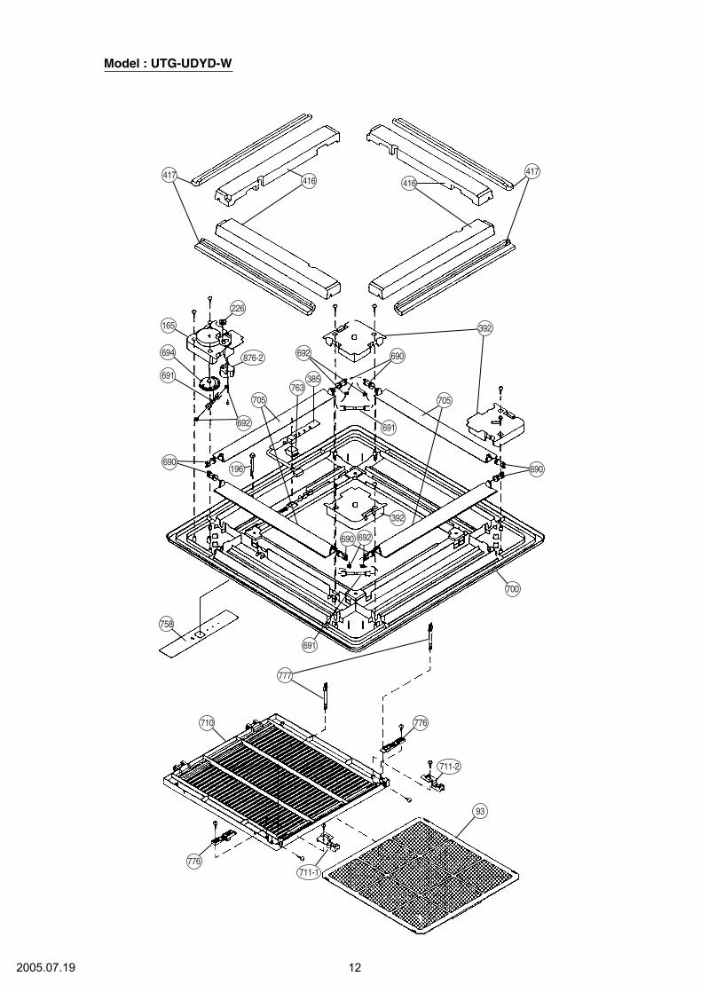
Model : UTG-UDYD-W
417416 416
392
690
691
694
165
226
692
692
763705
385
705
690
700
392
692690
691
777
776
776
758
710
93
690196
417
691
876-2
711-2
711-1
122005.07.19

Model : AOY18LMAK2
132005.08.18
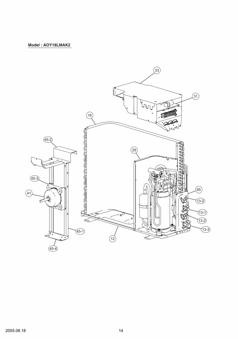
142005.08.18
31
85
13-2
13-1
13-2
13-345-1
45-4
45-3
45-2
29
16
12
41
33
Model : AOY18LMAK2
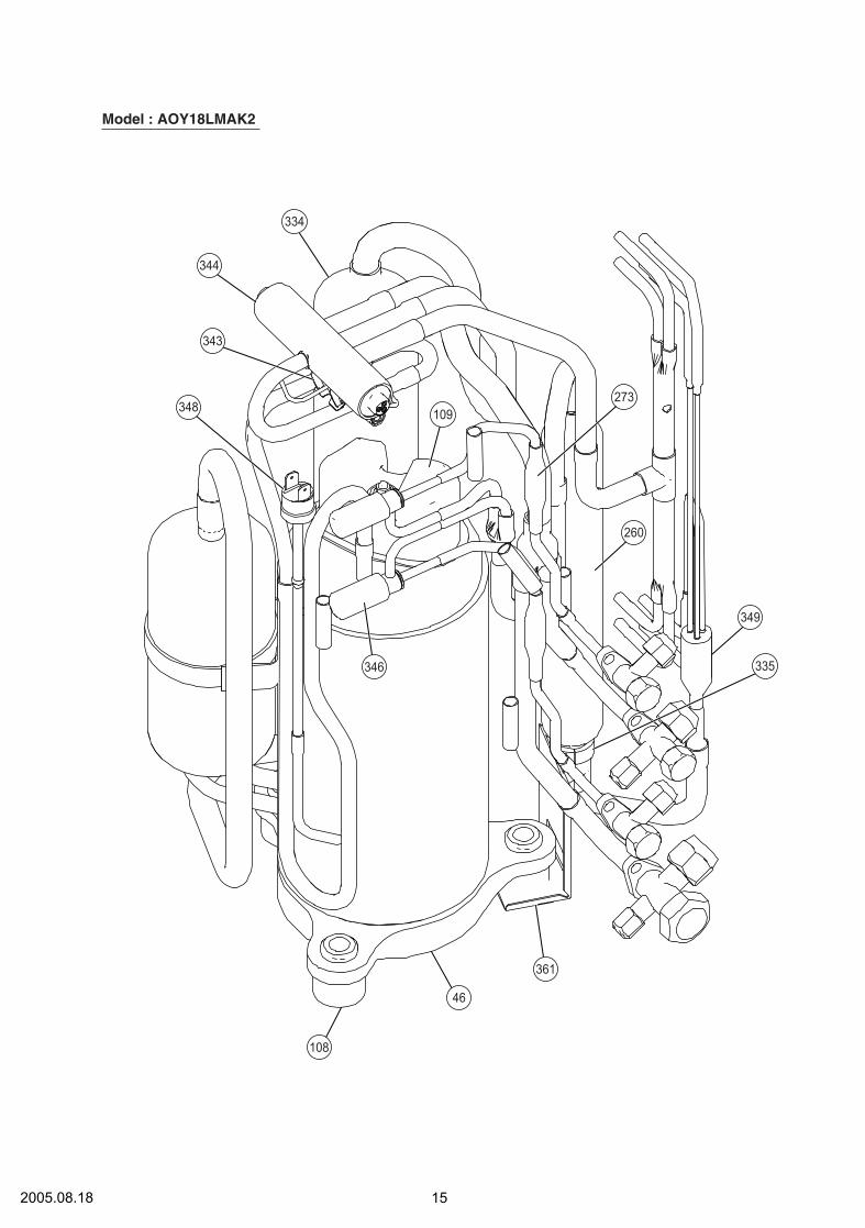
152005.08.18
273
260
349
335
361
346
109
334
344
343
348
46
108
Model : AOY18LMAK2

162005.08.18
346
345
26-1
26-2
Model : AOY18LMAK2

34 Capacitor (Fan Motor) 970430504667 Rubber 9361279001
117-3 Special Washer M6 313306391007127 Drain Hose 9359659013138 Separate Wall-A 9359647003146 Evaporator Assy-IN 9373214014160 Drain Pan 9359651000164 Fan Motor Assy-IN 9601040064184-1 Thermo. Spring-A 313728262708185 Rubber Bushing 313005066051
187 Clamp No. 1219 313361271706196 Clamp SKB-150 313035356905223 Control Box 9359661016234 Thermistor Assy-Room 9703299032235 Thermistor Assy-Pipe 9703297014236 Controller PCB Assy 9704557933240 Remote Control Unit 9371190037244 Pipe Cover 9359646006287 Cap (Power) 9352173011301 Clamp NK-2N 313985355201
313 Hooking Wire 9359983002338 Motor Fixture 9359656005381 Locking Spacer 313209391506395 Supporter (Eva. ) 9373179016399 Air Duct 9359660002411 9359655008430 Clamp NK-7N 313095365602457 Drain Pan Support 9359652007462 Top Cover Plate 9359642015464 9359643005
465 9359645009467 Drain Port 313005415658468 Special Nut-A (Large) 313005446653469 Special Nut-B (Small) 313005446759470 Separate Wall-B 9359648000474 Turbo Fan 9359658009475 Turbo Fan Rubber 9366013006476-1 Special Nut M8 313005360755476-2 Special Washer 301801185049476-3 Special Washer 9359954002
478 Sensor M. Bracket 9359654001479 Float Switch 313005416154482 Pump Unit 9359974000484 Hanger Metal 9359644002488 Drain Pan Plug 9359653004495 Clamp No. 2U46 9352715006514 Control Box Cover 9359662006628 Locking Spacer-B 313005446558629 EMI Filter 0400197119652-1 Therm. Holder Pipe 313806262805
743 Remote Control Holder Case 9305642014797 Separate Wall-C 9359649007798 Pump Hook Bracket 9359650003815 Terminal-3P 9900203016824-3 Fuse 0600222512834 Wire Cover 9359878001835 Cushion-A (For Pump) 9352211003836 Cushion-B (For Pump) 9356084016875 Filter PCB Assy 9704561213964 Flare Nut-1/2 -----
965 Flare Nut-B 9351062019989-1 Cord Clamp-A 9359822011989-2 Cord Clamp-B 9359823018990 Distributor Assy 9373034049
9704305046936127900131330639100793596590139359647003937321401493596510009601040064313728262708313005066051
3133612717063130353569059359661016970329903297032970149704557940937119003793596460069352173011313985355201
93599830029359656005313209391506937317901693596600029359655008313095365602935965200793596420159359643005
93596450093130054156583130054466533130054467599359648000935965800993660130063130053607553018011850499359954002
9359654001313005416154935997400093596440029359653004935271500693596620063130054465580400197119313806262805
9305642014935964900793596500039900203016060022251293598780019352211003935608401697045612139373267010
9351062019935982201193598230189373034049
When you order parts, please make a photocopy of this pageand fill the number of the parts in the "Order" column.
INDOOR UNIT
Ref.No. Description
AUY12LBAB AUY14LBAB
Ord.Q'ty
Part No.
PARTS LIST
Supporter-A
Body-A
Body-B
Ref.No.
Description Ord.Q'ty
93 Filter 9359632009165 Motor Cover 9359623014196 Clamp SKB-150 313035356905226 Motor Gear 9359629009385 Indicator PCB Assy 9702224011
9359622017392 Cover-A416 Insulation (Panel)-A 9359620006417 Insulation (Panel)-B 9359621003
93596260089359627005
690 Joint-A691 Joint-B
692 Joint Shaft 9359625001694 Cam Gear 9359628002
9359619017700 Panel705 Louver 9359624011710 Intake Grille 9370126006711-1 Filter Clamp-A 9359634003711-2 Filter Clamp-B 9359635000
763 Receiver Cover 9359630005776 Grille Stopper 9359633013
777 Grille Hook 9359761006876-2 Step Motor-V 9360307019
758 Decoration Plate-A(UTG-UDYD-W)
9360039019
Part No.
GRILLE ASSY (UTG-UDYD-W)
172005.07.19
When you order parts, please make a photocopy of this pageand fill the number of the parts in the "Order" column.182006.04.07
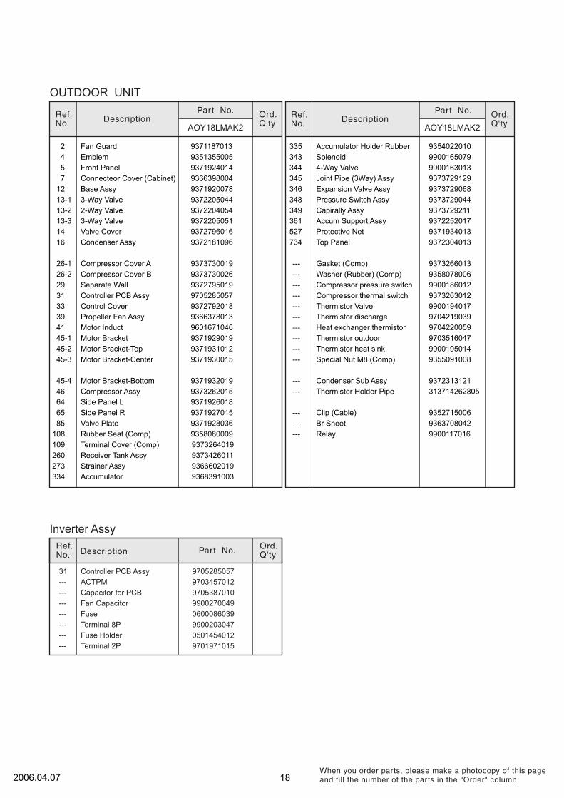
OUTDOOR UNIT
2 Fan Guard 93711870134 Emblem 93513550055 Front Panel 93719240147 Connecteor Cover (Cabinet) 9366398004
Inverter Assy
45-1 Motor Bracket 937192901945-2 Motor Bracket-Top 937193101245-3 Motor Bracket-Center 9371930015
Ref.No. Description Ord.
Q'ty
Part No.
12 Base Assy 937192007813-1 3-Way Valve 937220504413-2 2-Way Valve 9372204054
16 Condenser Assy 9372181096
39 Propeller Fan Assy 936637801341 Motor Induct 9601671046
26-1 Compressor Cover A 937373001926-2 Compressor Cover B 9373730026
31 Controller PCB Assy 970528505729 Separate Wall 9372795019
33 Control Cover 9372792018
--- Capacitor for PCB 9705387010--- Fan Capacitor 9900270049--- Fuse 0600086039--- Terminal 8P 9900203047--- Fuse Holder 0501454012--- Terminal 2P 9701971015
--- ACTPM 970345701231 Controller PCB Assy 9705285057
Ref.No. Description
AOY18LMAK2Ord.Q'ty
Part No.
AOY18LMAK2
Ref.No. Description
Ord.Q'tyPart No.
--- Clip (Cable) 9352715006--- Br Sheet 9363708042--- Relay 9900117016
--- Gasket (Comp) 9373266013
345 Joint Pipe (3Way) Assy 9373729129346 Expansion Valve Assy 9373729068
527 Protective Net 9371934013734 Top Panel 9372304013
361 Accum Support Assy 9372252017349 Capirally Assy 9373729211348 Pressure Switch Assy 9373729044
335 Accumulator Holder Rubber 9354022010343 Solenoid 9900165079344 4-Way Valve 9900163013
14 Valve Cover 937279601613-3 3-Way Valve 9372205051
--- Thermister Holder Pipe 313714262805--- Condenser Sub Assy 937231312145-4 Motor Bracket-Bottom 9371932019
46 Compressor Assy 9373262015
65 Side Panel R937192601864 Side Panel L9371927015
85 Valve Plate 9371928036108 Rubber Seat (Comp) 9358080009
--- Washer (Rubber) (Comp) 9358078006
Thermistor heat sink 9900195014
--- Compressor pressure switch 9900186012--- Compressor thermal switch 9373263012--- Thermistor Valve 9900194017--- Thermistor discharge 9704219039
--- Thermistor outdoor 9703516047--- Heat exchanger thermistor 9704220059
------
Special Nut M8 (Comp) 9355091008
109 Terminal Cover (Comp) 9373264019260 Receiver Tank Assy 9373426011273 Strainer Assy 9366602019334 Accumulator 9368391003
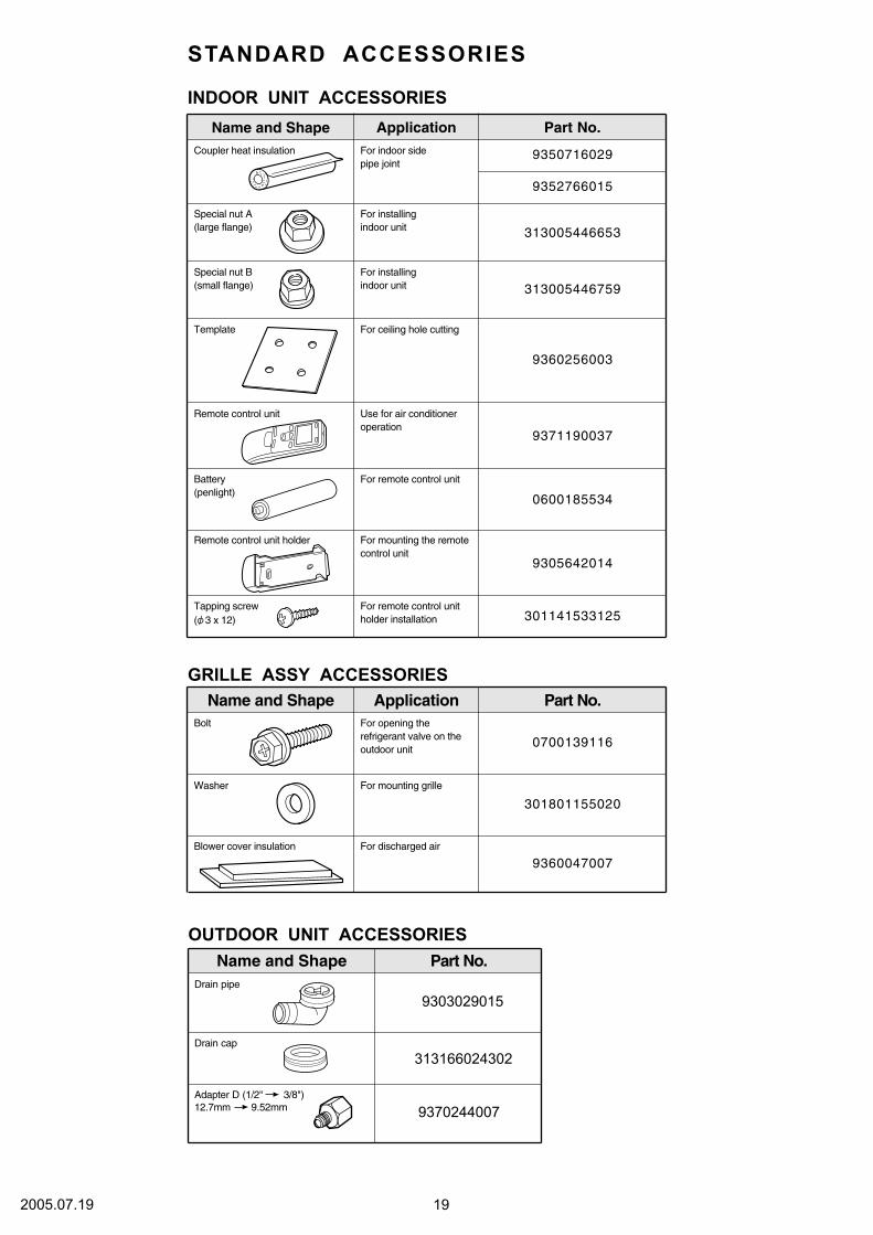
Part No.
OUTDOOR UNIT ACCESSORIESName and Shape
313166024302
9303029015
Drain cap
Drain pipe
9370244007Adapter D (1/2" 3/8")12.7mm 9.52mm
192005.07.19
Application
Name and Shape Application Part No.
Part No.
9350716029
9352766015
313005446653
313005446759
9371190037
9360256003
0600185534
9305642014
301141533125
INDOOR UNIT ACCESSORIES
Name and Shape
0700139116
301801155020
9360047007
GRILLE ASSY ACCESSORIES
Coupler heat insulation For indoor sidepipe joint
Special nut A(large flange)
For installingindoor unit
Special nut B(small flange)
For installingindoor unit
Remote control unit Use for air conditioneroperation
Battery(penlight)
For remote control unit
Remote control unit holder For mounting the remotecontrol unit
Tapping screw For remote control unitholder installation
Bolt For opening therefrigerant valve on theoutdoor unit
Washer For mounting grille
Blower cover insulation For discharged air
Template For ceiling hole cutting
STANDARD ACCESSORIES
( 3 x 12)

0507G2882