Embed Size (px)
Citation preview

CONTENTS
SPECIFICATIONS . . . . . . . . . . . . . . . . . . . . . 1
OUTLINE AND DIMENSIONS . . . . . . . . . . . 2
REFRIGERANT SYSTEM DIAGRAM . . . . . 4
ERROR CONTENTS . . . . . . . . . . . . . . . . . . . 9
CIRCUIT DIAGRAM . . . . . . . . . . . . . . . . . . . 5
INDOOR PCB CIRCUIT DIAGRAM . . . . . . 7
OUTDOOR PCB CIRCUIT DIAGRAM . . . . 8
DISASSEMBLY ILLUSTRATION . . . . . . . . . 10
STANDARD ACCESSORIES . . . . . . . . . . . . 24
PARTS LIST . . . . . . . . . . . . . . . . . . . . . . . . . 21
Models
Indoor unit Outdoor unit
RY-14LAROM-24LA2
RY-18LA
INVERTER MULTI
AIR CONDITIONER
FLOOR CONSOLE /UNDER CEILINGDUAL type
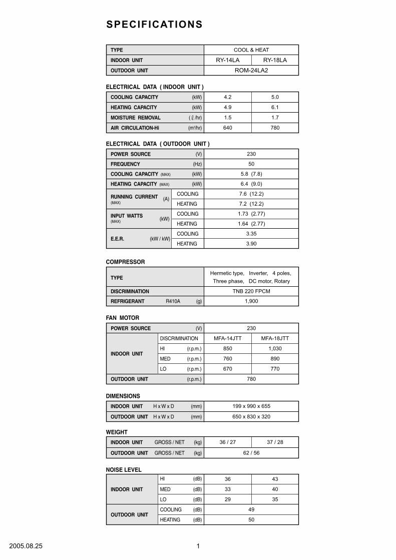
4.2
4.9
5.0
6.1
(kW)
(kW)
(V) 230
COOLING CAPACITY (MAX)
HEATING CAPACITY (MAX)
COOLING
HEATING
COOLING
HEATING
COOLING
HEATING
(Hz) 50
(A)
(kW)
(kW)
(kW)
(kW / kW)
7.6 (12.2)
7.2 (12.2)
5.8 (7.8)
6.4 (9.0)
(m3/hr)
ELECTRICAL DATA ( OUTDOOR UNIT )
ELECTRICAL DATA ( INDOOR UNIT )
COMPRESSOR
DIMENSIONS
Hermetic type, Inverter, 4 poles,
Three phase, DC motor, Rotary
TNB 220 FPCM
R410A (g) 1,900
(V) 230
HI
DISCRIMINATION
(r.p.m.)
MED (r.p.m.)
LO (r.p.m.)
(r.p.m.) 780
H x W x D (mm)
H x W x D (mm) 199 x 990 x 655
650 x 830 x 320
FAN MOTOR
WEIGHT
GROSS / NET (kg)
GROSS / NET (kg) 36 / 27 37 / 28
62 / 56
( /hr)
1.73 (2.77)
1.64 (2.77)
3.35
3.90
1.5
640
850
MFA-14JTT
760
670
1.7
780
MFA-18JTT
1,030
890
770
12005.08.25
SPECIFICATIONS
COOLING CAPACITY
HEATING CAPACITY
COOL & HEAT
RY-18LARY-14LA
ROM-24LA2
TYPE
INDOOR UNIT
OUTDOOR UNIT
POWER SOURCE
FREQUENCY
RUNNING CURRENT
E.E.R.
MOISTURE REMOVAL
AIR CIRCULATION-Hi
TYPE
DISCRIMINATION
REFRIGERANT
POWER SOURCE
INDOOR UNIT
OUTDOOR UNIT
HI
MED
(dB)
(dB)
LO
COOLING
HEATING
(dB)
(dB)
(dB)
50
NOISE LEVEL
36
29
49
43
33 40
35
INDOOR UNIT
OUTDOOR UNIT
INDOOR UNIT
OUTDOOR UNIT
INDOOR UNIT
OUTDOOR UNIT
(MAX)
INPUT WATTS(MAX)
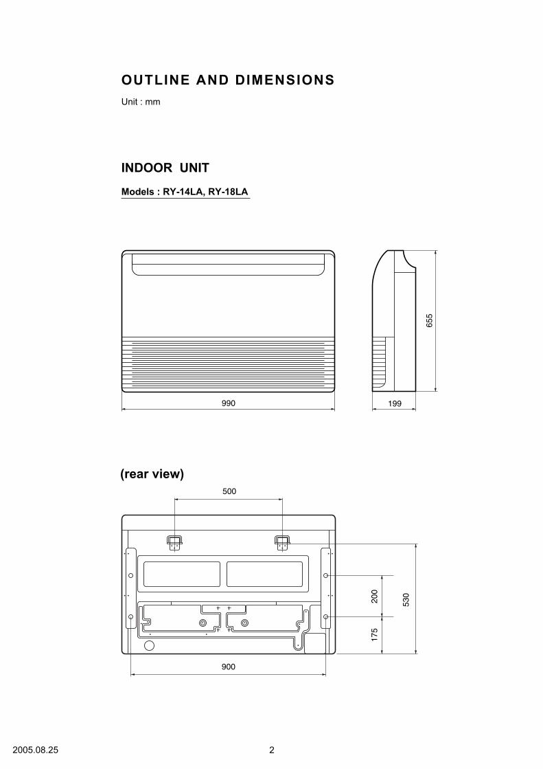
OUTLINE AND DIMENSIONS
INDOOR UNIT
Unit : mm
990
900
500
655
530
200
175
199
(rear view)
Models : RY-14LA, RY-18LA
22005.08.25
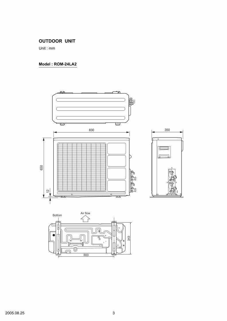
OUTDOOR UNIT
Unit : mm
Model : ROM-24LA2
Air flowBottom
603
343
350830
650
12
32005.08.25
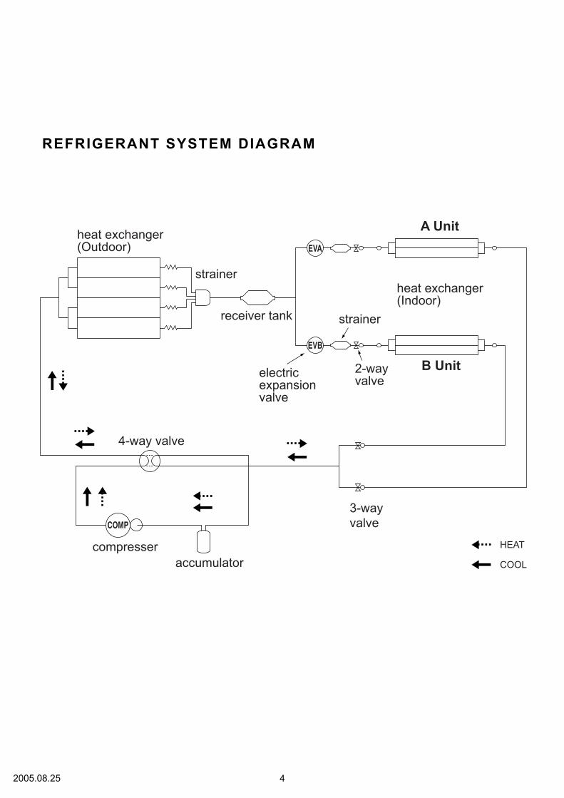
REFRIGERANT SYSTEM DIAGRAM
A Unit
B Unit
heat exchanger(Indoor)
heat exchanger(Outdoor)
3-way
valve
2-wayvalve
accumulator
compresser
4-way valve
COMP
electricexpansionvalve
strainer
strainerreceiver tank
EVA
EVB
HEAT
COOL
42005.08.25

Models :
RY-14LA
RY-18LA
CIRCUIT DIAGRAM
52005.08.25
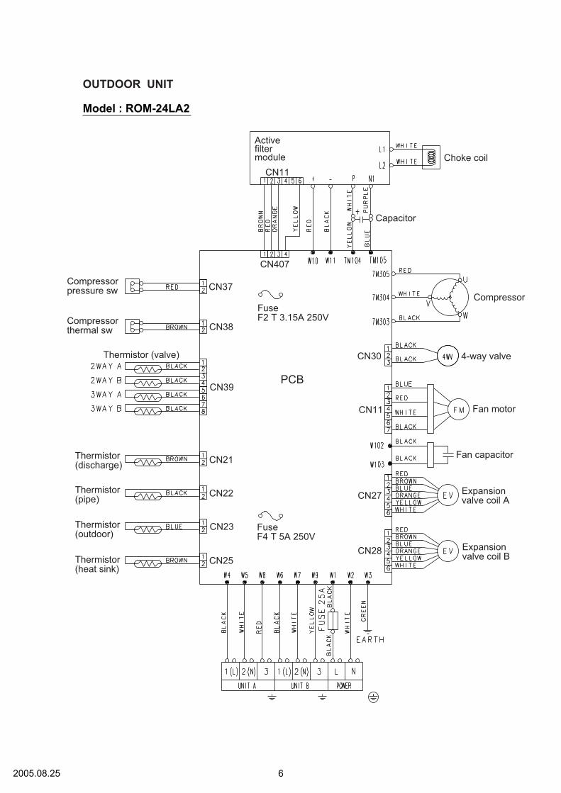
OUTDOOR UNIT
Thermistor(heat sink)
Expansionvalve coil B
Expansionvalve coil A
Fan capacitor
Fan motor
4-way valve
Compressor
Choke coil
Capacitor
PCBCN39
CN38
CN37
CN407
CN11
CN21
CN22
CN25
CN27
CN11
CN30
CN28
CN23
Compressorpressure sw
Activefiltermodule
Compressorthermal sw
Thermistor (valve)
FuseF2 T 3.15A 250V
FuseF4 T 5A 250V
Thermistor(outdoor)
Thermistor(pipe)
Thermistor(discharge)
Model : ROM-24LA2
62005.08.25

CO
NT
RO
LL
ER
PC
B A
SS
Y
IN
DO
OR
P
CB
C
IR
CU
IT
D
IA
GR
AM
Mo
dels
: R
Y-1
4L
A
RY
-18L
A
76
77 8 9
10 6
73
25
26
35
34
50
47
27
18
17
16
13
12
11 5
28
29
30
31 32
62
61
53
64 78
79
80
24
23
22
15
14
60
69
70
31
2
X2
X1
21
20
19
46
45
44
43
48
49
51
52
36
37
38
39
40
63
42
41
59
58
57
56
72
71
33
6747
75
68
74
65
66
55
54321
P15
P16
P17
P122
P123
P05
P04
VD
D0
VD
D1
AV
RF
0
AV
RF
1
AV
SS
VS
S0
VS
S1
I C
XT
2
P124
P125
P126
P127
P65
P66
P02
P64
P63
P62
P61
P60
P120
P37
P35
P34
P67
P30
P31
P32
P40
P41
P42
P24
P23
RE
SE
T
P43
P44
P45
P03
P12
P13
P14
P121
P00
P01
P55
P54
P53
P52
P51
P130
P20
P21
P22
P25
P26
P27
P50
P33
P36
P56
P46
P57
P47
XT
1
P131
P72
P71
P70
P11
P10
IO
G
IO
G
C1248
18
14
10
4325
1
10
8
7
91
16
12
5
13
4
14
15
3 2 5 4 3 2
12
13
14
15
No.1
No.3
No.2
AU
TO
RE
STA
RT
RO
OM
TE
MP
ER
AT
UR
E C
OR
RE
CT
ION
( H
EAT
ING
OP
ER
AT
ION
)
RO
OM
TE
MP
ER
AT
UR
E C
OR
RE
CT
ION
( H
EAT
ING
OP
ER
AT
ION
)
CN
9-1
CN
9-5
CN
9-4
CN
9-3
CN
9-2
CN
1-1
CN
1-3
CN
1-2
CU
ST
OM
CO
DE
SW
ITC
HIN
G
CU
ST
OM
CO
DE
SW
ITC
HIN
G
CU
ST
OM
CO
DE
SW
ITC
HIN
G
4 3 2 1
8 7 6 5
DO
D I
CK
CS
VC
C
NC
NC
GN
D
CN
15-1
CN
15-3
CN
15-2
CN
14-1
CN
14-2
CN
14-4
CN
14-3
CN
10-1
CN
10-5
CN
10-4
CN
10-3
CN
10-2
CN
11-1
CN
11-5
CN
11-4
CN
11-3
CN
11-2
CN
13-1
CN
13-2
CN
13-4
CN
13-3
CN
13-7
CN
13-6
CN
13-5
CN
13-8
+C
41
10
/
25
V
5V
12
V
CN
13
B8
B-X
AS
K-1
-A
DIS
PL
AY
BO
AR
D
CN
17
B3B
-XA
KK
-1-A
BL
AC
K
CN
17-1
CN
17-3
CN
17-2
L2
L3
L4
123
+ -
No.3
No.1
No.2
FA
N D
EL
EY
SW
ITC
HIN
G(
HE
AT
ING
OP
ER
AT
ION
)
FA
N T
YP
E S
WIT
CH
ING
RE
MO
TE
TY
PE
SW
ITC
HIN
G
75 6
+ -
10
7
1
3 223
1
8
11
6
14
3
11
61
9
16
10
7 51
2
94
13
21
5
16
16
11
CN
8-1
BL
AC
K
CN
8-2
BL
AC
K
CN
7-2
GR
AY
CN
7-1
GR
AY
BR
OW
N
RE
D
OR
AN
GE
YE
LL
OW
WH
ITE
BR
OW
N
RE
D
OR
AN
GE
YE
LL
OW
WH
ITE
BR
OW
N
RE
D
OR
AN
GE
YE
LL
OW
WH
ITE
BR
OW
N
RE
D
OR
AN
GE
YE
LL
OW
WH
ITE
1 2 3 4 8 5 7 6
BR
OW
N
RE
D
OR
AN
GE
YE
LL
OW
GR
AY
WH
ITE
PU
RP
LE
BL
UE
BR
OW
N
RE
D
OR
AN
GE
YE
LL
OW
GR
AY
WH
ITE
PU
RP
LE
BL
UE
OP
ER
AT
E
TIM
ER
LO
UV
ER
LO
UV
ER
OU
TP
HA
201
SB
X18
10
-2
2
UL1430 A
WG
28
UL1430 A
WG
28
UL1430
AW
G28
C4
20
.01
<F
>
5V
R5
2
10
K
<1
/10
W>
R53
10
K
<1
/10
W>
R5
1
1.0
K
<1
/10
W>
R5
4
47
<
1/1
0W
>
C4
0
0.0
1
<F
>
5V
CR
5
10
00
P
<R
>1
2V
12
V
12
V
5V
5V R
76
10
K
<1
/10W
>
R
75
1
0K
<1
/10
W>
C4
5
0.1
<F
>
5V
5V
I C
8
PS
T6
00
C3
21
C4
4
0.1
<F
>
R5
5
10
K
<1
/10
W>
X1
CS
TS
05
00
MG
03
-T
0.0
1 <
F>
x 3
C31
C1
6C
43
R8
1
1.0
K
<1/1
0W
>
R7
1
1.0
K
<1/1
0W
>
R7
2
1.0
K
<1/1
0W
>
SW
4
DS
S8
03
I C
11
-1
BA
10
358
D7
DA
22
6U
I C
11
-2
BA
10
35
8
R62
4.7
K
<1/1
0W
>
R65
3
90
<1
/10
W>
5V
Q6
2S
C2
71
2
10
K <
1/1
0W
> x
3R
70
R6
9R
80
R6
6
10
K
<1
/10
W>
R64
28
K (
1%
)
<1
/10
W>
R
63
15
.4K
(1
%)
<
1/1
0W
>
5V
R6
1
10
K
<1
/10W
>
R6
0
10
K
<1
/10
W>
Q5
2S
C2
71
2
CR
7
0.0
1
<F
>
I C
6 (
1/7
)
uPA
20
03
GR
C1
0.1
<F
>
R6
7
1.0
K
<1
/10
W>
R6
8
1.0
K
<1
/10
W>
10
K <
1/1
0W
> x
3C
R4
CR
3C
R2
14
V
I C
4 (
7/7
)
uPA
20
03
GR
I C
5 (
1/7
)
uPA
20
03
GR
14
V
I C
6 (
2/7
)
uPA
20
03
GR
R5
6
BZ
1
PK
M1
3E
PY-4
000
14
VR
57
1.0
K
<1
/10
W> B Z
14
V
5V
5V
5V
Q4
DT
C12
4E
KA
R4
9
1.0
K
<1
/10
W>
C3
8
0.0
1
<F
>
R4
7
39
0
<1
/10W
>
R48 10K
<1/10W>
HA
JE
M-A
CN
14
B4
B-X
H-A
M
M M
5V
FLO
AT
SW
ITC
H
C
15
B3
B-X
AR
K-1
-A R
ED
C4
9
0.0
1
<F
>
5V
5V
RJ2
10
K
<1
/10
W>
RJ1
1
.0K
<1
/10
W>
R
58
1
0K
<1
/10
W>
R
100
1
0K
<1
/10
W>
B2
B-X
AK
K-1
-A
B
LA
CK
B2
B-X
AS
K-1
-A
CN
7
CN
8
C3
4
0.1
<F
>
C3
7
0.1
<F
>
R4
3
10
K (
1%
)
<1
/10
W>
R4
5
49
.9K
(1
%)
<1
/10
W>
RO
OM
TE
MP
ER
AT
UR
E T
HE
RM
IST
OR
PIP
E T
EM
PE
RAT
UR
E T
HE
RM
IST
OR
CN
10
B5B
-XA
SK
-1-A
W
HIT
E
LO
UV
ER
( U
P / D
OW
N )
LO
UV
ER
( R
IGH
T / L
EF
T )
C
N1
1
B5
B-X
AR
K-1
-AR
ED
IND
ICAT
OR
PC
B
EZ
-096
4H
SE
-D
CN
20
1
8P
-JC
C201
0.1
<F
>
C202
10/
25V
+S
W2
01
MA
NU
AL A
UT
O
SW
ITC
H
EV
Q
PA
G 04
K
D201
SLR
-32
5 <
RE
D>
D204
SLR
-32
5 <
OR
G>
D203
SLR
-32
5 <
OR
G>
D202
SLR
-32
5 <
GR
N>
R201 330 <
1/4
W>
R204 330 <
1/4
W>
R203 330 <
1/4
W>
R202 330 <
1/4
W>
5V
C39
0.1
<F
>
I
C7
BR
93L
46R
F
R5
0
10
K
<1
/10
W>
C3
5
10
00
P
<R
>
C3
2
10
00
P
<R
>
R44
1.0
K
<1/1
0W
>
R4
4
1.0
K
<1
/10
W>
10
K <
1/1
0W
> x
3
R7
7R
78
R7
9
5V
12V
14V
5V
+
I C
2
78
12
I C
3
780
5
C1
1
10
/
25
V
C5
4
0.0
1
<F
>
10
K <
1/1
0W
> x
4
R5
9R
97
R9
8R
99
NCJM
10
C4
7
0.1
<F
>
C1
5
0.1
<F
>
+ C
14
10
0/
6.3
V
C13
0.1
<F
>
5V
5V
VA
1
47
0V
<T
NR
>
PR
IMA
RY
SE
CO
ND
AR
Y
SW
2
DR
S4
016
-5I
C 1
0
H I
200
2
10
K <
1/1
0W
> x
4
R2
9R
30
R3
1R
32
1.0
K <
1/1
0W
> x
4R
33
R3
4
R3
5
R3
6
5V
CR
1
0.0
1
<R
>
R9
3
90
<1
/10
W> C
R6
0.0
1
<R
>
Q3
DT
C1
24
EK
A
R
10
1
0K
<1
/10W
>
C1
7
0.0
1
<F
>
R1
4
10
K
<1
/10W
>
I C
5 (
1/7
)
uPA
20
03
GR
C2
6C
27
C2
8
0.0
1 <
F>
x 4
C2
9
5V 5
V
+ -
14
V1
4V
VA
2
47
0V
<T
NR
>
R9
3
10
K
<1
/10
W>
R9
6
10
K
<1
/10
W>
R9
5
10
K
<1
/10
W>
R9
4
10
K
<1
/10
W>
I C
5 (
5/7
)
uPA
20
03
GR
K 2
K 1
K 3
K 4
S
SR
1
G3
MC
-20
1P
L-V
D
5V
CN
9
B5
P-S
HF
-1A
AW
HIT
E
TE
ST
SW
1D
SS
80
3
0.0
1 <
F>
x 3
C1
0C
12
C3
0
R4
0
1.0
K
<
1/1
0W
>
R4
1
1.0
K
<
1/1
0W
>
R4
2
1.0
K
<
1/1
0W
>
0.0
1 <
F>
x 4
C22
C2
3C
24
C2
5
I C
6 (
4/7
)
uPA
20
03
GR
R2
8
1.0
K <
1/1
0W
> x
4
R2
8
R2
5
R2
6
R2
7
10K
<1
/10
W>
x 3
R3
9R
38
R3
7
10
K <
1/1
0W
> x
4
R2
1R
22
R2
3R
24
JM
6
C10
1
0.2
2
C1
03
0.0
1
C1
04
0.0
1
+
C8
10
0/
6.3
V
R
7
3
30
<1
/4W
>
LF
10
1
EL
F1
7N
01
5A
VA
101
47
0V
+
VA
10
2
47
0V
SA
10
1
<3
60
0>
FH
10
2F
H1
01
F1
01
3.1
5A
<B
ET
>
W1
02
TM
10
1
E1
01
W1
03
W1
04
NL
E31
2(N
)
OU
TD
OO
R U
NIT
PO
WE
R S
OU
RC
E
22
0 /
24
0V
50
Hz
DR
AIN
PU
MP
F M
FA
N M
OT
OR
YE
LL
OW
/ G
RE
EN
BL
UE
PU
RP
LE
PIN
K
RE
D
WH
ITE
BL
AC
K
UL1015 AWG14 RED
UL1015 AWG14 BLACK
UL1015 AWG14 WHITE
UL1015 A
WG
20
WH
ITE
UL1015 A
WG
20
WH
ITE
FA
N C
APA
CIT
OR
45
0V
2.3
uF
CN
4
B2
P3
-VH
-B-Y
YE
LL
OW
CN
1
B3
P5
-VH
-B-C
BL
AC
K
CN
6
B2
P3
-VH
-B-E
BL
UE
R88
12
0
<1
/2W
>
C3
0.2
2
<R
E>
R2
1.5
<R
S-2
W>
C5
10
0/
450
V
D1
D3
SB
60
Q
2
2S
C1
815
R3
1
00
<1
/10
W>
Q1
2S
C4
236
R4
33
0K
<S
PR
H-2
W>
R5
62K
<R
S-2
W>
C6
47
00
P
<E
CQ
M>
D
5
1S
R1
39
-600
D1
0
1S
R1
39
-600
C7
0
.04
7
<E
CQ
B>
R6
1
00
<1
/2W
>
D2
D1
FL2
0U
D4
D1
FL
20
U
D3
MT
ZJ5
.1B
D6
D2
FL
20
U
JM
1
JM
3
JM
2
T1
SW
ITC
HIN
G T
RA
NS
FO
RM
ER
ZF
T29
B0
1
C
9
10
00
/25
V
+
R8 10K
<1/10W>
R2
0
1.0
K
<1
/10
W>
R1
9
1.0
K
<1
/10
W>
R1
8
1.0
K
<1
/10
W>
10
K <
1/1
0W
> x
3R
15
R1
6R
17
0.0
1 <
F>
x 3
C2
1C
20
C1
9R
1
3.3
<R
C-5
W>
PO
WE
R S
UP
PLY
PC
B
K0
1A
L-0
40
8H
SE
-P0 K
2
G5
SB
-14
K1
G5
SB
-14
K3
G5
SB
-14
K4
G5
NB
-1A
CN
5
B6
P1
1-V
H-B
WH
ITE
CN
6-2
CN
6-1
CN
4-1
CN
4-2
CN
5-2
CN
5-6
CN
5-5
CN
5-4
CN
5-3
CN
5-1
UL1015
AW
G18
BL
AC
K
UL1015 A
WG
18
WH
ITE
UL1015 AWG16
GREENI
C 1
uP
D780058G
C -
108-8
BT-
01
RY
-14LA
: K
01A
L-0
414H
SE
-F1
RY
-18LA
: K
01A
L-0
40D
HS
E-F
1
72005.0
8.2
5

12
V
12
V
5V
12
V
12
V
BL
AC
K
BL
AC
K
BR
OW
N
BR
OW
N
BL
AC
K
WH
ITE
RE
D
BL
UE
( A
CT
PM
)
18
V
C4
15
0.0
1<
F>
A
C4
13
0.0
1<
F>
A
A
R4
37
2
70
<1
/10
W>
(1%
)
R4
38
2
70
<1
/10
W>
(1%
)5
V
R4
04
5
10
<1
/10
W>
18
V
I C
40
2P
S2
56
1L
-1-V
Q4
01
DT
C1
14
EK
A
2
13
214 3
CN
40
7B
4B
-XA
SK
-1-A
W
HIT
E
AC
TP
M C
ON
TR
OL
41 2 3
BR
OW
N
RE
D
OR
AN
GE
YE
LL
OW
UL
10
07
AW
G2
4
TM
10
2
TM
10
3
W1
1B
LA
CK
D1
01
D2
5X
B6
0
+ -
1 4
2 3
UL
10
15
AW
G1
4B
LA
CK
+ -
I C
41
4S
AC
T3
20
10
A
L1
L2
P N1
UL
10
15
AW
G1
4R
ED
W1
0R
ED
2P
T
ER
MIN
AL
WH
ITE
PU
RP
LE
BL
UE
YE
LL
OW
+C
20
41
20
04
50
V
EM
I F
ILT
ER
RF
C-8
1
TW
12
W1
3
18
V
TM
10
4
TM
10
5
A
R2
01
22
0K
<2
W>
C1
16
0
.1<
HC
P>
UL
10
15
A
WG
14
2T
EM
I F
ILT
ER
T
FC
-25
-
15
-12
CH
OK
E C
OIL
L=
0.3
MH
3
0A
C1
15
0
.1<
HC
P>
C1
14
1
.0<
LE
>
R2
00
ZP
R0
RC
H4
00
1 4
2 3
12
C1
13
0.0
15
<Y
E>
C1
12
0.0
15
<Y
E>
12
V
K
10
1D
W1
2D
1
L
4R
CV
25
15
-01
0P
F0
51
2 34
C1
09
0.0
15
<Y
E>
C1
10
0.0
15
<Y
E>
C1
11
1.0
<Y
E>
5V 1 2
3
+C
60
<P
J>
22
0/1
6V
5V
C1
07
2
.2<
LE
>
1.0
<L
E>
x 2
C1
17
, C
11
8
TM
10
0
L
2N
20
05
00
K
C1
04
0.0
33
<Y
E>
C1
05
0.0
33
<Y
E>
C1
06
1.0
<L
E>
C1
02
0.0
33
<Y
E>
C1
03
0.0
33
<Y
E>
L1
RC
V2
51
5-0
10
PF
05
C1
01
1.0
<L
E>
VA
10
14
70V
<T
NR
>
VA
10
24
70
V<
TN
R>
SA
10
0R
A-3
02
MV
A1
03
47
0V
<T
NR
>
R6
0
1.0
K<
1/1
0W
>(1
%)
CT
1C
T-1
BD
60
DA
N2
17
U
C6
40
.1<
F>
VR
1B
2K
R6
8
22
K<
1/1
0W
>
12V
T1
JP
Z-2
00
15
V
1 2 3 6 7 89
10
12
13
15
16
1
2
3I
O
G
C3
5C
36
0.0
1 <
F>
x 2
5V
10
K<
1/1
0W
>
x
2
R4
07
R4
03
I
C4
01
PS
25
61
L-1
-V 18
V
18
V1 2
34 34
21
I
C4
01
PS
25
61
L-1
-V
15
V
15
V
R1
15
1
.0K
<1
/10
W>
5V
CO
NT
RO
LLE
R P
CB
AS
SE
MB
LY (
MA
IN P
CB
)
EZ
-0037H
UE
-C
Mo
del :
RO
M-2
4L
A2
OU
TD
OO
R P
CB
C
IR
CU
IT
D
IA
GR
AM
82005.08.25
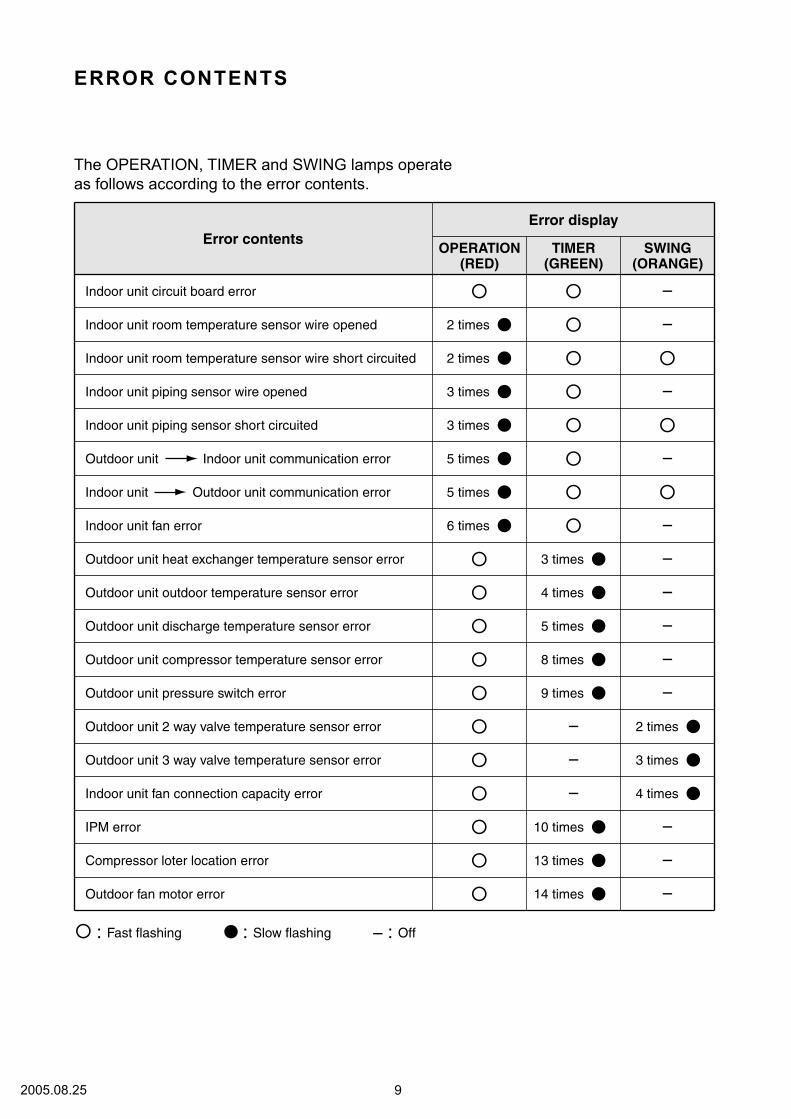
ERROR CONTENTS
The OPERATION, TIMER and SWING lamps operate
as follows according to the error contents.
Error display
OPERATION TIMER SWING(RED) (GREEN) (ORANGE)
Error contents
Indoor unit circuit board error
Indoor unit room temperature sensor wire opened
Indoor unit room temperature sensor wire short circuited
Indoor unit piping sensor wire opened
Indoor unit piping sensor short circuited
Outdoor unit Indoor unit communication error
Outdoor unit compressor temperature sensor error
Outdoor unit heat exchanger temperature sensor error
Outdoor unit outdoor temperature sensor error
2 times
2 times
3 times
3 times
5 times
Indoor unit fan error 6 times
5 times
8 times
Outdoor unit pressure switch error
Outdoor unit 2 way valve temperature sensor error
Outdoor unit 3 way valve temperature sensor error
9 times
Indoor unit fan connection capacity error
IPM error 10 times
Compressor loter location error 13 times
Outdoor fan motor error 14 times
Outdoor unit discharge temperature sensor error 5 times
3 times
4 times
3 times
2 times
4 times
: Fast flashing : Slow flashing : Off
Indoor unit Outdoor unit communication error
92005.08.25
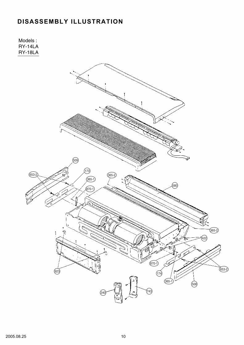
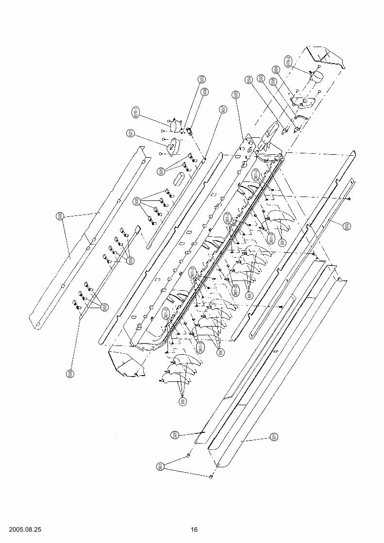
DISASSEMBLY ILLUSTRATION
Models :
RY-14LA
RY-18LA
580
422
508
923
509
173
174
365-2
365-2
365-1
653-2
653-2
365-1
870-1
870-1
240743
102005.08.25

439
160
418
470
764
577
127
124
124
552
235
553
138
187
68
108
68
578
870-2
588-2
588-1
184-1
196-1
574-2
574-1
112005.08.25

755
581
56
164
109
338
67
56
126
653-1
122005.08.25

416
417
385
868
771
488
472
473
443
8-1
132005.08.25
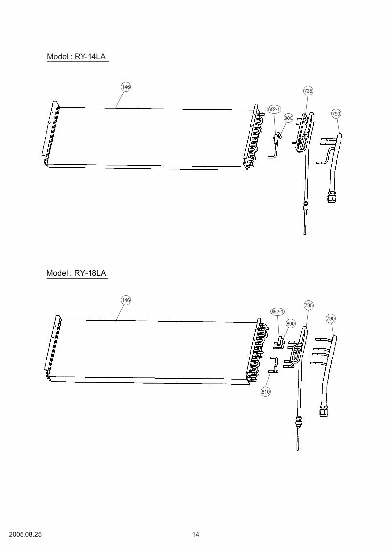
Model : RY-14LA
810
800
652-1
790
735
146
800
652-1790
735146
Model : RY-18LA
142005.08.25

514
34
187
381
422
982
628
381
625
195223
628
234
36-2
824-3
187-1
731-2
629-1
815-1
236
152005.08.25
684
558555
554
520
521
505
505
505
321
320
361
69
69
69
69
502
505
506
500
407
408
503
876-2
876-1
361-2
361-2
361-2
361-3
361-3
361-3
361-2
162005.08.25

Model : ROM-24LA2
172005.08.25

182005.08.25
31
85
13-2
13-1
13-2
13-345-1
45-4
45-3
45-2
29
16
12
41
33
Model : ROM-24LA2
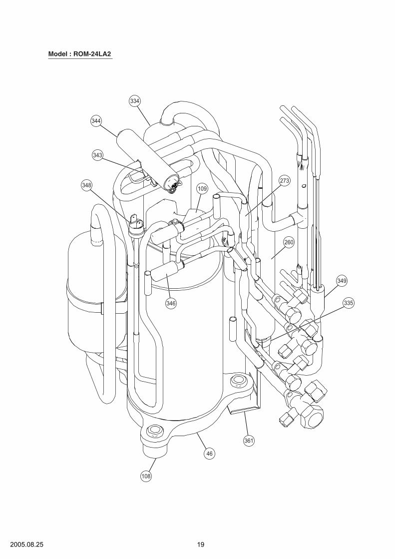
192005.08.25
273
260
349
335
361
346
109
334
344
343
348
46
108
Model : ROM-24LA2
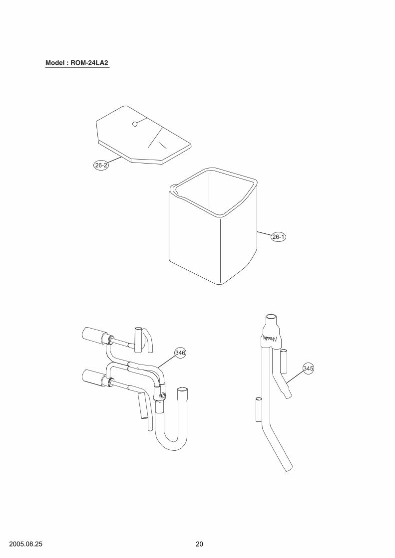
202005.08.25
Model : ROM-24LA2
346
345
26-1
26-2
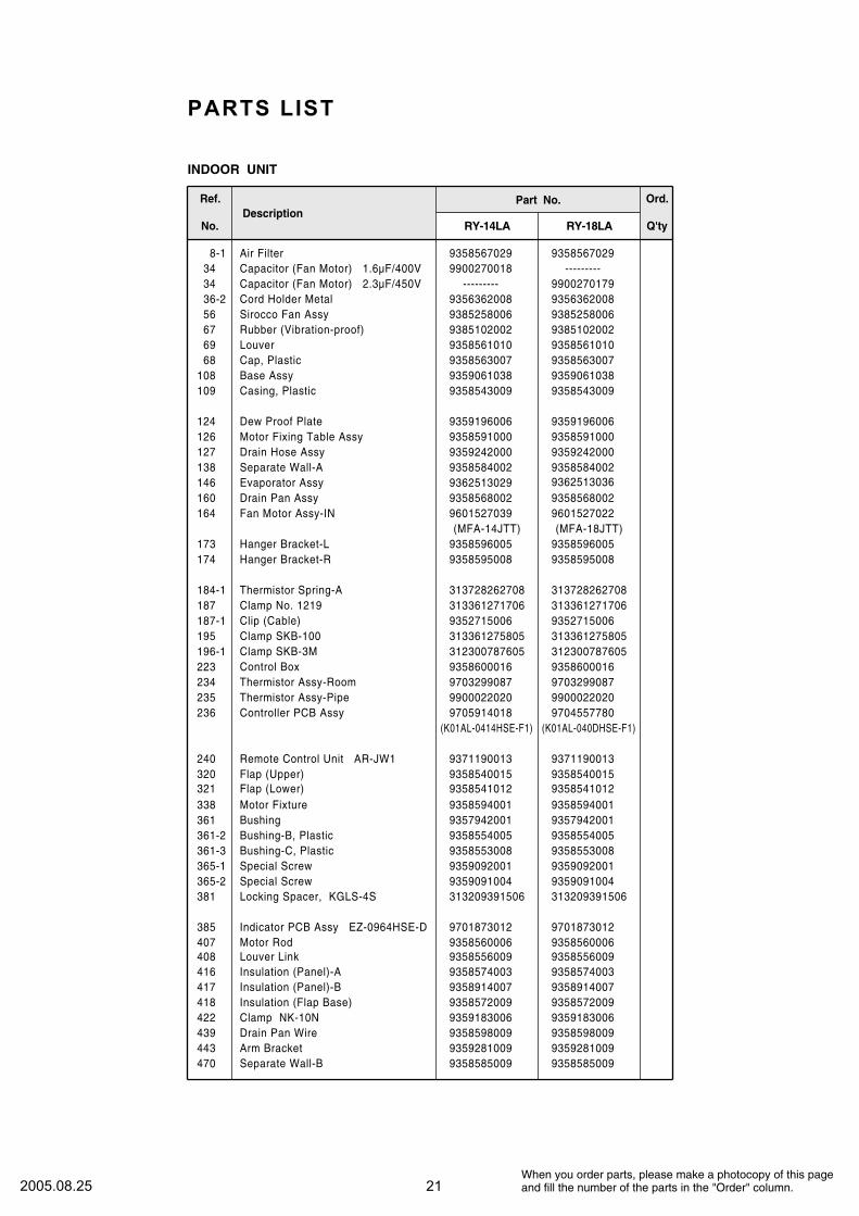
PARTS LIST
When you order parts, please make a photocopy of this pageand fill the number of the parts in the "Order" column.
INDOOR UNIT
Ref.
No.Description
Ord.
Q'ty
Part No.
RY-18LARY-14LA
69 Louver 9358561010
8-1 Air Filter 9358567029
34 Capacitor (Fan Motor) 2.3µF/450V 9900270179
36-2 Cord Holder Metal 9356362008
56 Sirocco Fan Assy 9385258006
67 Rubber (Vibration-proof) 9385102002
68 Cap, Plastic 9358563007
108 Base Assy 9359061038
109 Casing, Plastic 9358543009
124 Dew Proof Plate 9359196006
126 Motor Fixing Table Assy 9358591000
127 Drain Hose Assy 9359242000
138 Separate Wall-A 9358584002
9362513036
160 Drain Pan Assy 9358568002
(MFA-18JTT)
173 Hanger Bracket-L 9358596005
174 Hanger Bracket-R 9358595008
9358561010
9358567029
---------
34 Capacitor (Fan Motor) 1.6µF/400V ---------9900270018
9356362008
9385258006
9385102002
9358563007
9359061038
9358543009
9359196006
9358591000
9359242000
9358584002
146 Evaporator Assy 9362513029
9358568002
164 Fan Motor Assy-IN
(MFA-14JTT)
96015270229601527039
9358596005
9358595008
184-1 Thermistor Spring-A 313728262708
187 Clamp No. 1219 313361271706
187-1 Clip (Cable) 9352715006
195 Clamp SKB-100 313361275805
196-1 Clamp SKB-3M 312300787605
223 Control Box 9358600016
234 Thermistor Assy-Room 9703299087
235 Thermistor Assy-Pipe 9900022020
240 Remote Control Unit AR-JW1 9371190013
236 Controller PCB Assy 9704557780
(K01AL-040DHSE-F1)
320 Flap (Upper) 9358540015
321 Flap (Lower) 9358541012
338 Motor Fixture 9358594001
361 Bushing 9357942001
361-2 Bushing-B, Plastic 9358554005
361-3 Bushing-C, Plastic 9358553008
365-1 Special Screw 9359092001
365-2 Special Screw 9359091004
381 Locking Spacer, KGLS-4S 313209391506
385 Indicator PCB Assy EZ-0964HSE-D 9701873012
407 Motor Rod 9358560006
408 Louver Link 9358556009
416 Insulation (Panel)-A 9358574003
417 Insulation (Panel)-B 9358914007
418 Insulation (Flap Base) 9358572009
422 Clamp NK-10N 9359183006
439 Drain Pan Wire 9358598009
443 Arm Bracket 9359281009
313728262708
313361271706
9352715006
313361275805
312300787605
9358600016
9703299087
9900022020
9371190013
9705914018
(K01AL-0414HSE-F1)
9358540015
9358541012
9358594001
9357942001
9358554005
9358553008
9359092001
9359091004
313209391506
9701873012
9358560006
9358556009
9358574003
9358914007
9358572009
9359183006
9358598009
9359281009
470 Separate Wall-B 93585850099358585009
212005.08.25
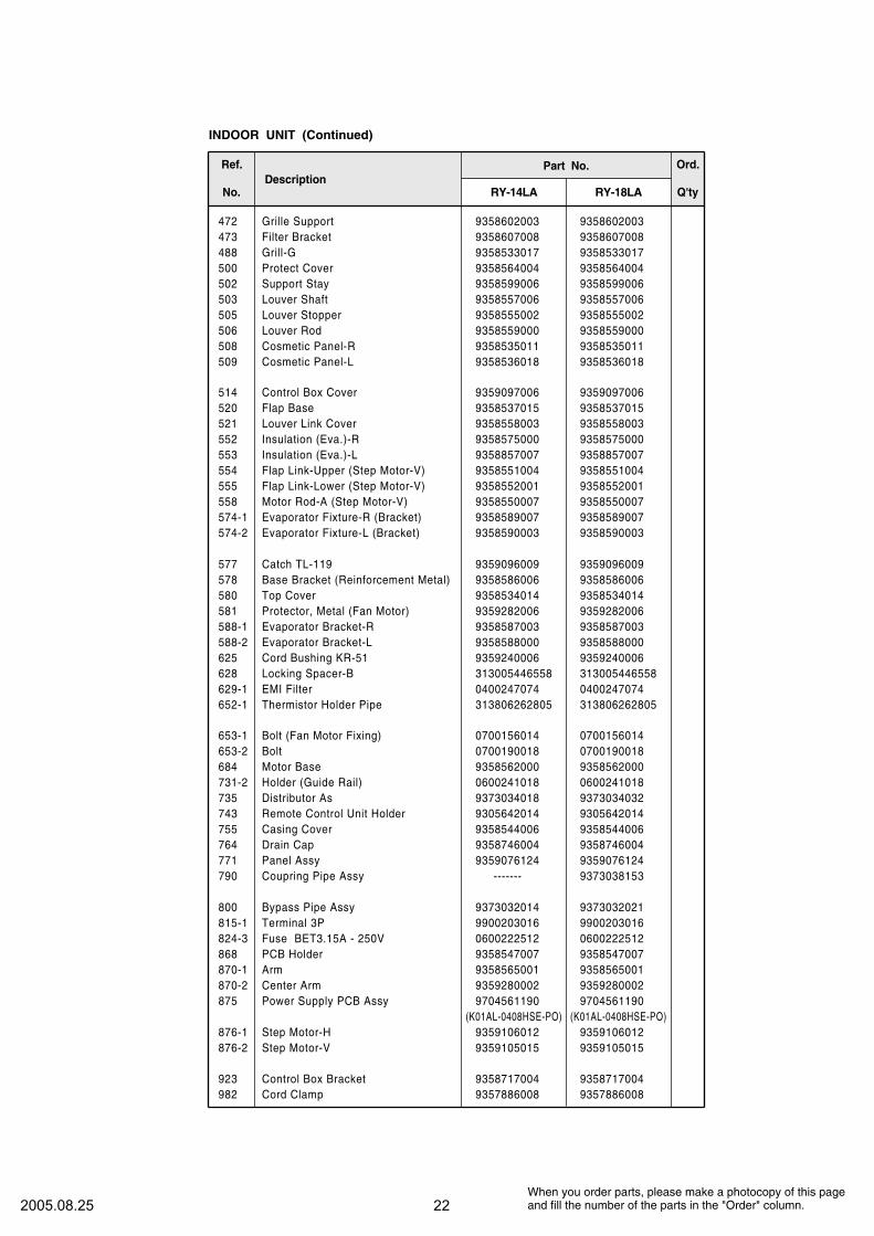
500 Protect Cover 9358564004
502 Support Stay 9358599006
503 Louver Shaft 9358557006
505 Louver Stopper 9358555002
506 Louver Rod 9358559000
508 Cosmetic Panel-R 9358535011
509 Cosmetic Panel-L 9358536018
514 Control Box Cover 9359097006
520 Flap Base 9358537015
521 Louver Link Cover 9358558003
552 Insulation (Eva.)-R 9358575000
553 Insulation (Eva.)-L 9358857007
554 Flap Link-Upper (Step Motor-V) 9358551004
555 Flap Link-Lower (Step Motor-V) 9358552001
558 Motor Rod-A (Step Motor-V) 9358550007
574-1 Evaporator Fixture-R (Bracket) 9358589007
574-2 Evaporator Fixture-L (Bracket) 9358590003
577 Catch TL-119 9359096009
578 Base Bracket (Reinforcement Metal) 9358586006
580 Top Cover 9358534014
581 Protector, Metal (Fan Motor) 9359282006
588-1 Evaporator Bracket-R 9358587003
588-2 Evaporator Bracket-L 9358588000
625 Cord Bushing KR-51 9359240006
628 Locking Spacer-B 313005446558
629-1 EMI Filter 0400247074
652-1 Thermistor Holder Pipe 313806262805
653-1 Bolt (Fan Motor Fixing) 0700156014
653-2 Bolt 0700190018
684 Motor Base 9358562000
731-2 Holder (Guide Rail) 0600241018
743 Remote Control Unit Holder 9305642014
755 Casing Cover 9358544006
764 Drain Cap 9358746004
771 Panel Assy 9359076124
735
790
800
Distributor As 9373034032
Coupring Pipe Assy
Bypass Pipe Assy 9373032021
815-1 Terminal 3P
9373038153
9900203016
824-3 Fuse BET3.15A - 250V 0600222512
868 PCB Holder 9358547007
870-1 Arm 9358565001
870-2 Center Arm 9359280002
876-1 Step Motor-H 9359106012
876-2 Step Motor-V 9359105015
923 Control Box Bracket 9358717004
982 Cord Clamp 9357886008
9704561190875 Power Supply PCB Assy
When you order parts, please make a photocopy of this pageand fill the number of the parts in the "Order" column.
(K01AL-0408HSE-PO)
9358564004
9358599006
9358557006
9358555002
9358559000
9358535011
9358536018
9359097006
9358537015
9358558003
9358575000
9358857007
9358551004
9358552001
9358550007
9358589007
9358590003
9359096009
9358586006
9358534014
9359282006
9358587003
9358588000
9359240006
313005446558
0400247074
313806262805
0700156014
0700190018
9358562000
0600241018
9305642014
9358544006
9358746004
9359076124
9373034018
9373032014
-------
9900203016
0600222512
9358547007
9358565001
9359280002
9359106012
9359105015
9358717004
9357886008
9704561190
(K01AL-0408HSE-PO)
INDOOR UNIT (Continued)
Ref.
No.Description
Ord.
Q'ty
Part No.
RY-18LARY-14LA
472 Grille Support 9358602003
473 Filter Bracket 9358607008
488 Grill-G 9358533017
9358602003
9358607008
9358533017
222005.08.25
When you order parts, please make a photocopy of this pageand fill the number of the parts in the "Order" column.
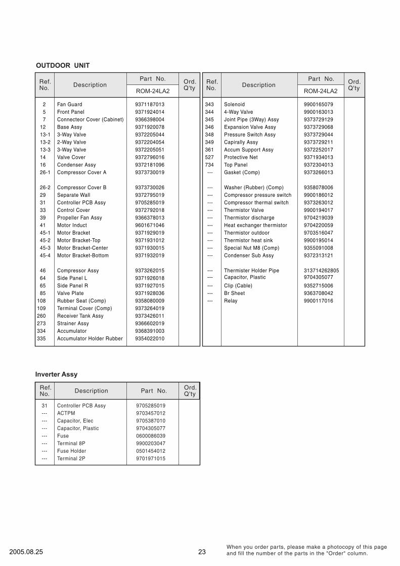
OUTDOOR UNIT
2 Fan Guard 9371187013
5 Front Panel 9371924014
7 Connecteor Cover (Cabinet) 9366398004
Inverter Assy
45-1 Motor Bracket 9371929019
45-2 Motor Bracket-Top 9371931012
45-3 Motor Bracket-Center 9371930015
Ref.No.
DescriptionOrd.Q'ty
Part No.
12 Base Assy 9371920078
13-1 3-Way Valve 9372205044
13-2 2-Way Valve 9372204054
16 Condenser Assy 9372181096
39 Propeller Fan Assy 9366378013
41 Motor Induct 9601671046
26-1 Compressor Cover A 9373730019
26-2 Compressor Cover B 9373730026
31 Controller PCB Assy 9705285019
29 Separate Wall 9372795019
33 Control Cover 9372792018
--- Capacitor, Elec 9705387010
--- Capacitor, Plastic 9704305077
--- Fuse 0600086039
--- Terminal 8P 9900203047
--- Fuse Holder 0501454012
--- Terminal 2P 9701971015
--- ACTPM 9703457012
31 Controller PCB Assy 9705285019
Ref.No.
DescriptionROM-24LA2
Ord.Q'ty
Part No.
ROM-24LA2
Ref.No.
DescriptionOrd.Q'ty
Part No.
--- Clip (Cable) 9352715006
--- Br Sheet 9363708042
--- Relay 9900117016
--- Gasket (Comp) 9373266013
345 Joint Pipe (3Way) Assy 9373729129
346 Expansion Valve Assy 9373729068
527 Protective Net 9371934013
734 Top Panel 9372304013
361 Accum Support Assy 9372252017
349 Capirally Assy 9373729211
348 Pressure Switch Assy 9373729044
343 Solenoid 9900165079
344 4-Way Valve 9900163013
14 Valve Cover 9372796016
13-3 3-Way Valve 9372205051
--- Thermister Holder Pipe 313714262805
--- Capacitor, Plastic 9704305077
--- Condenser Sub Assy 937231312145-4 Motor Bracket-Bottom 9371932019
46 Compressor Assy 9373262015
65 Side Panel R
937192601864 Side Panel L
9371927015
85 Valve Plate 9371928036
108 Rubber Seat (Comp) 9358080009
--- Washer (Rubber) (Comp) 9358078006
Thermistor heat sink 9900195014
--- Compressor pressure switch 9900186012
--- Compressor thermal switch 9373263012
--- Thermistor Valve 9900194017
--- Thermistor discharge 9704219039
--- Thermistor outdoor 9703516047
--- Heat exchanger thermistor 9704220059
---
---
Special Nut M8 (Comp) 9355091008
232005.08.25
109 Terminal Cover (Comp) 9373264019
260 Receiver Tank Assy 9373426011
273 Strainer Assy 9366602019
334 Accumulator 9368391003
335 Accumulator Holder Rubber 9354022010

1
4
2
1
1
1
4
4
1
1
4
2
6
1
1
1
1
Q'ty
INDOOR UNIT ACCESSORIES
Name and Shape Part No.Application
For positioning the indoor unit.
For under ceiling type.
For suspending the indoor unit from
ceiling.
For suspending the indoor unit on
the wall.
For fixing the wall bracket.
For indoor side pipe joint.
(Large pipe)
For indoor side pipe joint.
(Small pipe)
Adhesive type 70 x 230
For fixing the drain hose
L 280 mm
9358536018
9358535011
301171164104
9359107002
9358596005
9358595008
313806339400
301821112213
9358597002
301141164200
9350716012
313209328104
312300787605
9359242000
9359225003
313806350303
Tapping screw ( 4 x 10)
Tapping screw ( 4 x 20)
Installation template
Hanger bracket (left)
Hanger bracket- (right)
Anchor bolt (M12)
Special nut
Spring washer
Wall bracket
Cosmetic Panel-L
Cosmetic Panel-R
Coupler heat insulator (large)
Coupler heat insulator (small)
For fixing the drain hose.Nylon fastener (small)
Drain hose
Insulation (drain hose)
VT wire
S T A N D A R D A C C E S S O R I E S
The following installation parts are furnished. Use them as required.
242005.08.25
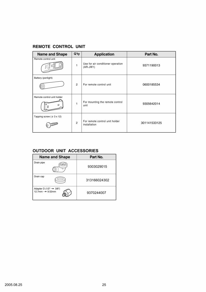
1
1
2
2
For remote control unit holderinstallation
Use for air conditioner operation(AR-JW1)
For remote control unit
For mounting the remote controlunit
9371190013
0600185534
9305642014
301141533125
Remote control unit holder
Tapping screw
Remote control unit
Battery (penlight)
Q'ty
REMOTE CONTROL UNIT
Name and Shape Part No.Application
( 3 x 12)
Part No.
OUTDOOR UNIT ACCESSORIES
Name and Shape
313166024302
9303029015
Drain cap
Drain pipe
9370244007
Adapter D (1/2" 3/8")
12.7mm 9.52mm
252005.08.25

0507G2890


