Embed Size (px)
Citation preview

Available online at www.sciencedirect.com
International Journal of Solids and Structures 45 (2008) 1513–1535
www.elsevier.com/locate/ijsolstr
Influence of wall constructions on the load-carrying capabilityof light-weight structures
H. Obrecht *, P. Fuchs, U. Reinicke, B. Rosenthal, M. Walkowiak
Lehrstuhl fur Baumechanik-Statik, Technische Universitat Dortmund, August-Schmidt-Strasse 6, D-44221 Dortmund, Germany
Received 7 February 2007; received in revised form 8 September 2007Available online 30 October 2007
Dedicated to Professor Choon Fong Shih, President of the National University of Singapore on the occasion of this 60th birthday.
Abstract
Results of systematic numerical studies are presented which suggest that suitable alternative wall constructions maylead to elastic load-carrying capacities of light-weight structures which significantly exceed those of conventionalmonocoque constructions, and that in certain cases this improvement may also be accompanied by a decrease inimperfection-sensitivity. Two kinds of wall modifications are considered: a hybrid wall construction where the skin of alight-weight structure is coated with a low-density material, and nonhomogeneous – in particular lattice and biaxiallycorrugated – wall constructions. The paper focuses on the elastic load-carrying behavior of shell- and plate-like structures,and structural efficiency is assessed on the basis of their bifurcation buckling resistance while other design criteria, such ase.g. stiffness and plasticity, are not taken into account.� 2007 Elsevier Ltd. All rights reserved.
Keywords: Auxetic lattices; Elastic buckling; Finite element method; Lattice structures; Light-weight structures; Load-carrying capability;Hybrid structures
1. Introduction
To ensure the economy, safety, and long-term reliability of lightweight structures, their load-carrying capa-bility should be as high and their imperfection-sensitivity as low as possible. Unfortunately, numerous inves-tigations on the buckling and postbuckling behavior of shells performed over the past decades seem to indicatethat optimizing the weight-efficiency of thin-walled compression members inevitably leads to a catastrophicbuckling behavior – and a correspondingly high imperfection-sensitivity – which in design practice is usuallyaccounted for via empirical knock-down factors (Arbocz and Singer, 2000; Brush and Almroth, 1978; Budian-sky, 1974, 1999; Hutchinson and Koiter, 1970; Koiter, 1945, 1963; NASA, 1965, 1968; Singer et al., 1997,2002; Thompson, 1972; Thompson and Lewis, 1972; Thompson and Supple, 1973). Well-known classical
0020-7683/$ - see front matter � 2007 Elsevier Ltd. All rights reserved.
doi:10.1016/j.ijsolstr.2007.10.017
* Corresponding author. Tel.: +49 231 755 5840; fax: +49 231 755 3532.E-mail address: [email protected] (H. Obrecht).
1514 H. Obrecht et al. / International Journal of Solids and Structures 45 (2008) 1513–1535
examples of this are monocoque shells and, in particular, the circular cylindrical shell under axial compressionas well as the spherical shell subjected to uniform external pressure. Perfect (elastic) configurations of thesestructures tend to fail suddenly, and their experimental buckling loads are merely a fraction of their respectivetheoretical values. Similar tendencies are typically also observed in the case of optimized structures such as, forexample, stringer-stiffened and sandwich shells.
On the other hand, the results of the numerical studies presented below indicate that suitable alternativewall constructions can lead to elastic load-carrying capacities which significantly exceed those of conventionalmonocoque structures, and that in certain cases this improvement may also be accompanied by a decrease inimperfection-sensitivity. Both effects are of considerable practical importance because they may justifyincreased allowable design loads and/or a corresponding reduction in structural weight. This opens the wayto interesting new types of lightweight construction.
Two kinds of wall modifications are considered here: In the first case – a hybrid wall construction – the skinof a light-weight structure is coated with a low-density material, while in the second nonhomogeneous wallconstructions are considered. In both instances the effective biaxial bending stiffness is increased (with onlya moderate or no increase in weight), which, in turn, leads to a significant improvement in the overallload-carrying capability.
The purpose of the present article is to explore the extent to which such alternative wall constructions mayincrease the load-carrying capability of thin-walled structures (with an emphasis on plates and shells) as well asto assess their potential usefulness as weight-saving alternatives to conventional kinds of light-weight con-struction. The treatment aims at baseline assessments of the efficiency of the structural configurations inves-tigated and is not meant to be exhaustive. In particular, structural comparisons are made solely on the basis ofelastic buckling resistance, and – as a first step – failure is equated with bifurcation buckling (see also Budian-sky, 1999). More specifically, linear elastic bifurcation loads are used as the primary strength criterion,whereas the influence of other relevant design factors, such as e.g. stiffness and/or plastic deformations, onthe load-carrying behavior have not been taken into account in this investigation. These aspects are the subjectof ongoing research.
All quantitative evaluations are based on systematic numerical analyses using the finite element codes ABA-QUS and ANSYS, and pertinent details concerning the computational models employed will be given in thelater chapters.
2. Hybrid wall constructions
From experiments on silicon rubber cylinders filled with rubber foam, and analytical results based on judi-ciously simplified mechanical models (Karam and Gibson, 1995), as well as preliminary numerical studiesreported in (Obrecht et al., 2006), one may conclude that substantial improvements in the elastic load-carryingcapability and weight-efficiency of thin-walled compression members are possible when their skin is coated –on one or both sides – with layers of a low-density material whose thicknesses are small in comparison with thestructure’s overall dimensions and which therefore make only a limited contribution to the total weight. Inaddition, some of the results indicate that such compliant layers may also lead to a reduced degree of imper-fection-sensitivity. As a result, coated shells of this type may have competitive weight- and strength-advanta-ges over more established types of thin-walled construction – such as e.g. monocoque, stiffened, or evensandwich configurations.
Since for axially compressed elastic circular cylindrical shells both the theoretical load-carrying capacity –given by the classical bifurcation stress rcl (see Eq. (1)) – and the imperfection-sensitivity are particularly high,they are ideal candidates for testing the effectiveness of such hybrid wall constructions. Taking the classicalbuckling and imperfection-sensitivity analyses by Koiter (1963) and Budiansky and Hutchinson (1972) on axi-ally compressed circular cylindrical shells as a starting point, the configuration shown in Fig. 1 was chosen asthe basic mechanical model. Its geometrical and material parameters are the shell’s thickness t, its radius R,length L, Young’s modulus Es, and Poisson’s ratio ms, as well as the thicknesses tc and to of the inner and outerlayers, and their respective Young’s moduli Ec and Eo, and Poisson’s ratios mc and mo. To facilitate the inter-pretation of the results given below, various thickness levels of the inner and outer layers (tc and to) are alsoplotted in the right-hand part of Fig. 1. Both hollow and coated, perfect and imperfect configurations are con-

Fig. 1. Axially compressed circular cylindrical shell: Configuration and loading (Shell: thickness t, radius R, length L, Young’s modulusEs, Poisson’s ratio ms; Inner and outer layers: thicknesses tc and to, Young’s moduli Ec and Eo, Poisson’s ratios mc and mo).
H. Obrecht et al. / International Journal of Solids and Structures 45 (2008) 1513–1535 1515
sidered, and – as will be discussed below – the imperfection was assumed to have the shape of the axisymmetricbuckling mode associated with the elastic bifurcation stress of the perfect hollow shell.
To verify the computational model, the numerical results for the hollow shell were first compared to thoseobtained by Koiter (1963) and Budiansky and Hutchinson (1972) who used semi-/analytical approaches. Weemployed the commercial finite element code ANSYS – using two-dimensional isoparametric shell elements(designated ‘Shell 63’) for the cylinder and three-dimensional solid elements (designated ‘Solid 45’) for thecompliant layers. In addition, perfect bonding between the two was modelled by suitably coupling the respec-tive degrees-of-freedom at the shell-coating interface. A typical finite element discretization for a perfect shellwith a coating applied only to its inner surface is plotted in Fig. 2. As can be seen, the mesh extends over theentire surface of the shell, and therefore no symmetry or periodicity conditions in the circumferential directionare needed. On the other hand, exploratory mesh-sensitivity analyses have shown that a sufficient degree ofnumerical accuracy can only be achieved with a comparatively large number of elements around the circum-ference. Also, as discussed later in connection with Fig. 14, the length L was chosen to be four times the wave-length of the classical axisymmetric buckling mode of the hollow shell, and periodic boundary conditions wereinvoked at both ends.
An analytical bifurcation analysis of an infinite, perfect hollow circular cylindrical shell leads to the classicalbuckling stress
rcl ¼Esffiffiffiffiffiffiffiffiffiffiffiffiffiffiffiffiffiffiffi
3ð1� v2s Þ
p � tR
ð1Þ
Fig. 2. Perfect shell with coated inner surface: Finite element mesh.
1516 H. Obrecht et al. / International Journal of Solids and Structures 45 (2008) 1513–1535
(see e.g., Koiter, 1963; Budiansky and Hutchinson, 1972), where, as indicated in Fig. 1, R and t are the radiusand thickness of the shell, and Es and ms denote Young’s modulus and Poisson’s ratio of its material. As is wellknown, rcl is a multiple eigenvalue that is associated with a large number (of order R/t) of coincident biaxiallyperiodic eigenmodes of the form
w ¼ t coskq0
2
xR
� �cos
s0q0
2
yR
� �ð2Þ
(Budiansky and Hutchinson, 1972), where x and y denote the axial and circumferential (length) coordinates,the axial and circumferential wave numbers k and s0 satisfy the following relationship (sometimes also calledthe ‘Koiter-circle’)
ðk � 1Þ2 þ s20 ¼ 1; ð3Þ
s0 and q0 are given by
s0 ¼2 � m
q0
; q0 ¼ffiffiffiffiffiffiffiffiffiffiffiffiffiffiffiffiffiffiffiffiffiffiffiffiffiffiffiffiffiffiffiffiffiffiffiffiffiffiffiffiffiffiffiffiffiffiffiffiffiffiffiffiffi
12ð1� v2s Þ
q� R
t
r; ð4Þ
and – to satisfy circumferential periodicity – m corresponds to an integer which increases monotonically fromzero (e.g. m = 0, 1, 2, etc.).
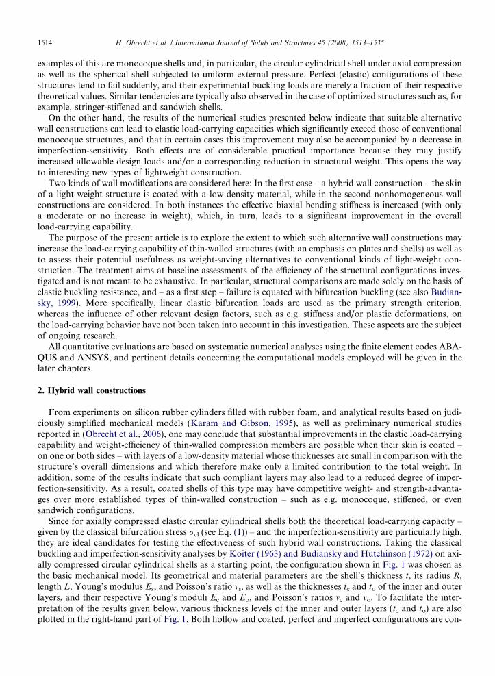
For the first nine integer values of m and the associated values of k (Eq. (3)), typical examples of the ana-lytical eigenmodes (2) are given in Fig. 3 for a shell with an R/t-value of 100. Note that for m = 0 and k = 2one obtains the classical axisymmetric buckling mode shown in the upper left corner of Fig. 3 (which will alsobe used as the shape of the initial geometric imperfections), whereas for all other combinations of m and k theeigenmodes are nonaxisymmetric and their axial and circumferential wavelengths follow from Eq. (3).
From numerical eigenvalue analyses one obtains the eigenmodes corresponding to the ten lowest eigen-values (associated with a bifurcation from the linear initial prebuckling path) plotted in Fig. 4. The respectiveeigenvalues are given below each mode as a multiple of the lowest bifurcation stress (which corresponds to thefirst, axisymmetric, mode and whose numerical value was practically identical to the classical buckling stress
Fig. 3. Perfect hollow shell: Analytically obtained coincident eigenmodes.

Fig. 4. Perfect hollow shell: Numerically obtained nearly-coincident eigenmodes.
H. Obrecht et al. / International Journal of Solids and Structures 45 (2008) 1513–1535 1517
rcl). For computational reasons, the numerical eigenvalues are not precisely equal – as they are in the analyt-ical solution – but up to the tenth eigenmode the differences are seen to be quite small.
Again following Koiter (1963) and Budiansky and Hutchinson (1972) – and as a further test of the validityof our numerical model – we also computed the bifurcation loads of an elastic hollow shell containing an ini-tial geometric imperfection in the shape of the first, axisymmetric, mode shown in Fig. 4. In the numericalanalyses the influence of (initial and subsequent) displacements on the prebuckling equilibrium state was takeninto account, and the values of the stresses rcr,imp (normalized by the classical buckling stress rcl) for which abifurcation from the nonlinear axisymmetric prebuckling equilibrium path into a nonaxisymmetric mode firstoccurs, are given in Fig. 5 (see also Obrecht et al., 2006) as a function of the imperfection amplitude wimp (nor-malized by the shell thickness t). As can be seen, there is a remarkably close agreement between the numericalresults and Koiter’s classical imperfection-sensitivity curve (Koiter, 1963; Hutchinson and Koiter, 1970;Budiansky and Hutchinson, 1972) – which, as is well known, yields an upper bound estimate of the influenceof the imperfection amplitude on the imperfect shell’s load-carrying capacity.
Fig. 5. Imperfection sensitivity: Analytical vs. numerical results.
1518 H. Obrecht et al. / International Journal of Solids and Structures 45 (2008) 1513–1535
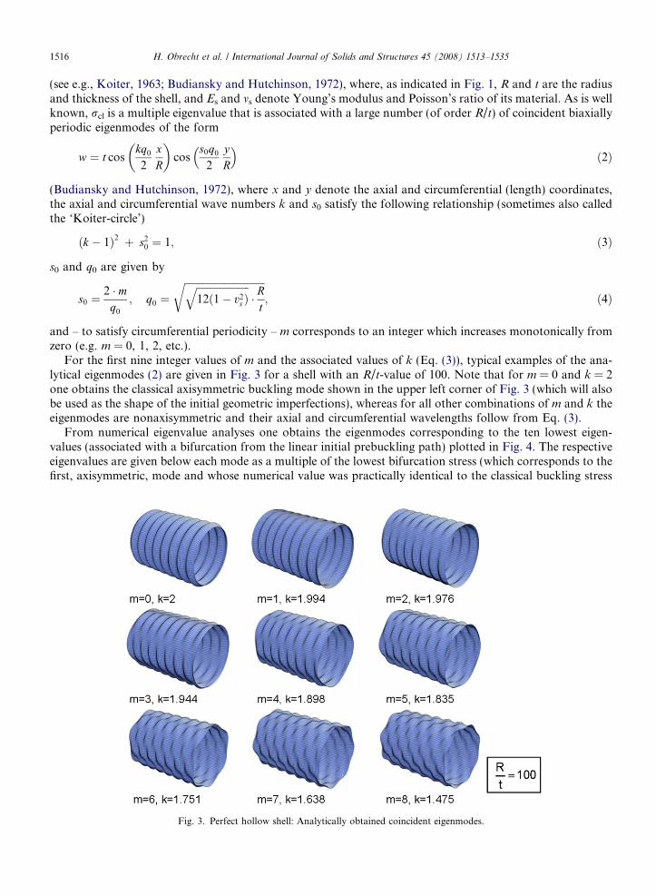
Based on these preliminary analyses for a hollow shell, we focused attention on the buckling behavior ofcoated configurations. First, an axially compressed perfect shell having, again, an R/t-ratio of 100 and a coat-ing applied only to the inner surface was considered (see Fig. 2), and – as before – solutions were obtained fora prescribed axial shortening of both the shell and the coating. For a layer with a thickness tc ranging from 2 to15 percent of the shell’s radius R, and the values of its Young’s modulus Ec ranging from 5 Æ 10�5 to 1 Æ 10�2
times that of the shell Es, one finds the buckling modes shown in Fig. 6. Here, unlike in the case of the hollowshell, all eigenvalues are distinct and the lowest ones always correspond to axisymmetric modes, whereas non-axisymmetric modes are associated with higher eigenvalues (which in many cases are not too different,however).
Concerning the mechanical properties of the coating, it is noteworthy that the Ec/Es-values considered aretypical of material combinations of practical interest. The ratio Ec/Es = 1 Æ 10�2, for example, is representativeof a steel shell coated with polymers (such as PE, PP, PVC, etc.) whereas smaller values of Ec/Es are charac-teristic of steel shells coated with e.g. rigid or flexible polymer foams.
Considering, for example, Ec/Es = 1 Æ 10�2, one obtains the eigenmodes in the last column of Fig. 6, and inFig. 7 (see also Obrecht et al., 2006) the corresponding bifurcation stresses rcr (normalized by the classical buck-ling stress rcl of the respective hollow shell) are plotted as a function of the coating thickness tc (normalized by theshell radius R). As can be seen, the dependence of rcr/rcl on tc/R is approximately bilinear, and the initial partclearly shows that even when the thickness of the low-density layer is small compared to the radius R (see alsoFig. 1), the elastic bifurcation stress rcr may be significantly larger than rcl. In addition, the slope of the curvein Fig. 7 drops sharply when the layer thickness tc exceeds approximately 10 percent of the radius. At that point,a fundamental change in the structure’s load-carrying behavior occurs, and the wavelengths of the bucklingmodes change drastically. This can be seen from the two eigenmodes included in Fig. 7 (which correspond toalmost identical layer thicknesses) as well as from those marked by dots in the last column of Fig. 6.
Thus, even a thin layer of a very compliant material may lead to a substantial improvement in the shell’selastic load-carrying behavior, and the relative benefits of adding such a material are most pronounced up to
Fig. 6. Perfect cylindrical shell with coated inner surface: Axisymmetric buckling modes corresponding to the lowest eigenvalues.

Fig. 7. Perfect cylindrical shell with coated inner surface: Influence of the layer thickness tc/R.
H. Obrecht et al. / International Journal of Solids and Structures 45 (2008) 1513–1535 1519
layer thicknesses which are less than about 10 percent of the radius. Shells with thicker layers and, in partic-ular, completely filled cylinders are clearly less weight-efficient because above tc/R = 0.1 the additional weightof the layer increases much faster than the buckling stress.
In the course of this investigation it has unfortunately not been possible to pinpoint the mechanical mech-anisms leading to this sudden change in behavior, but we fully agree with one of the reviewer’s comment thatthis point deserves to be studied in more detail. Interestingly, too, an analogous bilinear relationship is givene.g. in (Levy, 1990; Plaut et al., 1986) for the case of the buckling of an elastic beam on an elastic foundation.There, the dependence of the buckling load on a nondimensional parameter (corresponding to the ratio of thefoundation modulus to the beam’s moment of inertia) has the same characteristics as the curve in Fig. 7 andalso displays a sharp drop in its slope when a certain characteristic value of this stiffness quantity is exceeded.
For illustrative purposes, a typical qualitative plot of the stress state within the coating is given in Fig. 8. Ina longitudinal section of a shell with a layer thickness equal to 60 percent of the radius R it shows the distri-bution of the von Mises stresses at the bifurcation point and indicates that the stress levels are particularly
Fig. 8. Distribution of von Mises stresses at bifurcation for tc/R = 0.6.

1520 H. Obrecht et al. / International Journal of Solids and Structures 45 (2008) 1513–1535
high in the vicinity of the shell wall – which one would expect. On the other hand, Fig. 8 also shows that theinner parts of the relatively thick core are not stress-free – as might perhaps be concluded from the results ofbuckling analyses of beams and plates on an elastic continuum (e.g. Gough et al., 1940) which suggest that thestresses in the supporting medium decay very rapidly. As a result, semi-/analytical analyses of the interactionof structures with surrounding compliant media are frequently based on the simplifying assumption that thestresses within the supporting medium may be assumed to vanish only a short distance away from the inter-face. The reason that this seems to be different in the present case may lie in the fact that the load-carryingbehavior of the coated shell is fundamentally three-dimensional (involving axial, hoop and radial stresses)whereas in the case of a straight beam and plate the lateral in-plane stresses are either missing or becomenegligible.
For smaller values of Ec/Es (corresponding e.g. to a steel shell coated with rigid or flexible polymer foams)and a cylindrical shell with, again, only an inner layer and an R/t-value of 100, one obtains the curves plottedin Fig. 9 which are qualitatively similar to that in Fig. 7. They indicate that, for the respective range of param-eters, the thickness tc at which the slope drops sharply is essentially independent of Ec/Es and, again, typicallycorresponds to 10 percent of the radius R. As expected, the bifurcation stresses associated with Ec/Es < 1 Æ 10�2 are smaller than those in Fig. 7, but – except for very small values of Ec/Es – they are still sig-nificantly larger than the classical buckling stress rcl of the respective hollow shell.
A cross-plot of the previous – and some additional – results is given in Fig. 10, which shows the dependenceof the bifurcation stress rcr (normalized by rcl) on Ec/Es for given values of tc/R. As can be seen, for decreasingvalues of Ec/Es, the ratio rcr/rcl approaches unity – as it should – whereas for increasing values of both Ec/Es
and tc/R, all curves tend towards the upper solid line which represents results for a completely filled shell takenfrom Karam and Gibson (1995). In particular, Fig. 10 indicates that coating materials with Ec/Es less thanabout 5 Æ 10�4 are comparatively inefficient for any value of tc/R, and – vice-versa – coating thicknesses whichare distinctly smaller than tc/R = 0.05 are not very efficient for any value of Ec/Es. Moreover, for tc/R > 0.1, allcurves lie in a comparatively narrow band which indicates that in that particular parameter range, rcr/rcl isless dependent on tc/R than on Ec/Es. On the other hand, in the range 0.1 < tc/R < 1 the slopes of the curvesin Fig. 9 are small, so that even a comparatively large increase in tc/R (and in weight) results in only a small –or even negligible – increase in rcr/rcl. Thus, for shells with R/t = 100, only configurations with Ec/Es > 5 Æ 10�4 and 0.05 < tc/R < 0.1 seem to be of practical interest.
Results for shells with other R/t-ratios are given in Fig. 11, which shows the dependence of rcr/rcl on bothtc/R and R/t for comparatively thick (R/t = 50) to very thin (R/t = 1000) shells, and the particular value Ec/Es = 1 Æ 10�3 was chosen to circumvent numerical difficulties which were encountered in the case of very thinshells when Ec/Es becomes larger. On the other hand, Ec/Es = 1 Æ 10�3 corresponds to a material combinationwhich lies in the lower efficiency range, and more favorable results may be expected for larger values of Ec/Es.
Fig. 9. Perfect cylindrical shell with coated inner surface: Influence of tc/R and Ec/Es.
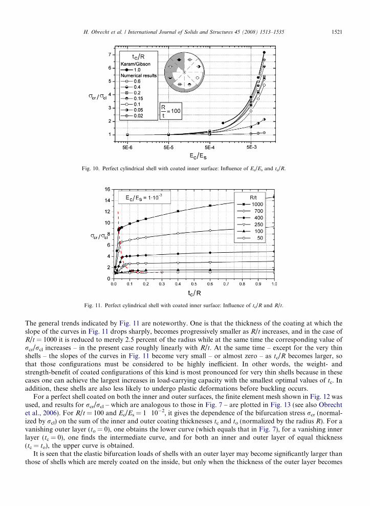
Fig. 10. Perfect cylindrical shell with coated inner surface: Influence of Ec/Es and tc/R.
Fig. 11. Perfect cylindrical shell with coated inner surface: Influence of tc/R and R/t.
H. Obrecht et al. / International Journal of Solids and Structures 45 (2008) 1513–1535 1521
The general trends indicated by Fig. 11 are noteworthy. One is that the thickness of the coating at which theslope of the curves in Fig. 11 drops sharply, becomes progressively smaller as R/t increases, and in the case ofR/t = 1000 it is reduced to merely 2.5 percent of the radius while at the same time the corresponding value ofrcr/rcl increases – in the present case roughly linearly with R/t. At the same time – except for the very thinshells – the slopes of the curves in Fig. 11 become very small – or almost zero – as tc/R becomes larger, sothat those configurations must be considered to be highly inefficient. In other words, the weight- andstrength-benefit of coated configurations of this kind is most pronounced for very thin shells because in thesecases one can achieve the largest increases in load-carrying capacity with the smallest optimal values of tc. Inaddition, these shells are also less likely to undergo plastic deformations before buckling occurs.
For a perfect shell coated on both the inner and outer surfaces, the finite element mesh shown in Fig. 12 wasused, and results for rcr/rcl – which are analogous to those in Fig. 7 – are plotted in Fig. 13 (see also Obrechtet al., 2006). For R/t = 100 and Ec/Es = 1 Æ 10�2, it gives the dependence of the bifurcation stress rcr (normal-ized by rcl) on the sum of the inner and outer coating thicknesses tc and to (normalized by the radius R). For avanishing outer layer (to = 0), one obtains the lower curve (which equals that in Fig. 7), for a vanishing innerlayer (tc = 0), one finds the intermediate curve, and for both an inner and outer layer of equal thickness(tc = to), the upper curve is obtained.
It is seen that the elastic bifurcation loads of shells with an outer layer may become significantly larger thanthose of shells which are merely coated on the inside, but only when the thickness of the outer layer becomes

Fig. 12. Perfect cylindrical shell coated on both surfaces: Finite element mesh.
Fig. 13. Perfect cylindrical shell coated on both surfaces: Influence of (tc + to)/R.
1522 H. Obrecht et al. / International Journal of Solids and Structures 45 (2008) 1513–1535
roughly equal to the radius R. From a practical point-of-view, however, this represents a rather exceptionalconfiguration. Moreover, in the weight-efficient range of lower values of tc and/or to, the respective curvesin Fig. 13 agree and, in particular, the transition values at which the slope drops sharply are practically iden-tical. Thus, in the parameter range of interest, internally and externally coated shells have essentially the sameload-carrying efficiency. For shells with both an inner and an outer layer of equal thickness, the bifurcationstress rcr corresponding to the transition point is about 60 percent larger than for shells with a layer on onlythe inner or the outer surface. Thus, by adding a second layer with a thickness of 10 percent of the radius R,one may achieve a substantial additional increase in load-carrying capacity, but for layer thicknesses less thanthe transition value (e.g. tc/R = to/R < 0.08) the curve for to = tc falls below those for to or tc = 0, which sug-gests that in that parameter range the elastic load-carrying capacity of shells with a two-sided coating is not aslarge as that of shells with a layer on only one side.
Finally, to gain information on the influence of a compliant coating on the notoriously high imperfection-sensitivity of axially compressed circular cylindrical shells, geometrically nonlinear numerical analyses werealso performed for configurations having an axisymmetric initial imperfection. As in the case of the hollowshell, buckling was taken to be associated with that value of the loading at which a bifurcation from the non-linear axisymmetric prebuckling path into a nonaxisymmetric eigenmode first occurs.
Interestingly, extensive convergence studies (not reported here in detail) have shown that taking the imper-fection-shape to be equal to that of the axisymmetric buckling mode of the perfect hollow shell (shown in the

H. Obrecht et al. / International Journal of Solids and Structures 45 (2008) 1513–1535 1523
upper left corner of Fig. 4) consistently gave lower bifurcation loads than imperfections in the shape of theaxisymmetric bifurcation modes of the respective coated shells (shown in Fig. 6). This is somewhat surprisingsince Koiter’s (1945, 1963) classic asymptotic analyses predict that for a hollow shell the imperfection-sensi-tivity is most severe when the imperfection-shape is equal to the bifurcation mode of the respective perfectstructure. Apparently this difference in behavior is due to the fact that a compliant layer leads to fundamentalchanges in the overall load-carrying properties of a coated shell.
The results given below were obtained for the numerical model shown in Fig. 14, where – for illustrativepurposes – part of the surface of a shell with an inner layer has been removed. It shows a cylinder with R/t = 100 and tc/R = 0.1 with an axisymmetric imperfection whose half-wavelength kimp is equal to that ofthe axisymmetric eigenmode of the corresponding perfect hollow shell (kcr) given in Fig. 4, and – as in the pre-vious analyses – the length L was taken to equal eight times kcr. In addition, the imperfection amplitude wimp
was varied from 0.05 to 1.5 times the shell thickness t, and Ec/Es was taken to vary between 1 Æ 10�4 and1 Æ 10�2. As in the case of the hollow shell, buckling was associated with the stress rcr,imp at which a nonax-isymmetric bifurcation from the nonlinear axisymmetric prebuckling path first occurs. For R/t = 100,tc/R = 0.1, Ec/Es = 1 Æ 10�2, and various values of wimp/t, the respective nonaxisymmetric bifurcation modesare plotted in Fig. 15, and the relationship between the associated bifurcation stresses rcr,imp (normalizedby the value rcr of the corresponding perfect configuration shown in Figs. 9 and 10) and wimp/t is given inFig. 16 (see also Obrecht et al., 2006).
The lower solid line represents the classical Koiter result for the hollow shell (shown in Fig. 5) while theupper curves are obtained for the coated shells. For Ec/Es approaching zero, the numerical results convergeto the classical lower curve – as they should – whereas for nonvanishing values of Ec/Es they lie above thelatter, thus indicating that the imperfection-sensitivity of the coated shells is consistently smaller than thatof the hollow shell. In particular, for Ec/Es = 1 Æ 10�2 (which gives one of the two upper curves in Fig. 16)and an imperfection amplitude equal to the shell thickness (wimp/t = 1.0), the buckling stress of the coatedshell is reduced to approximately 50 percent of rcr, whereas for a hollow shell the reduction amounts to about80 percent of rcl. If one takes into account that for the coated shell the corresponding value of rcr is approx-imately 5 times larger than rcl (see Fig. 7), the elastic load-carrying capacity of an imperfect coated shell of thiskind would be up to 12 times higher than that of a corresponding imperfect hollow shell.
Even though these results are based on the assumption that deformations remain purely elastic and addi-tional systematic investigations are clearly needed to clarify the – generally degrading – influence of plasticity,it does not seem unjustified to conclude that compliant coatings of this kind have an exceedingly positive effecton the overall load-carrying, buckling and postbuckling behavior of highly imperfection-sensitive structures,
Fig. 14. Imperfect cylindrical shell with coated inner surface: Parameters and finite element mesh.

Fig. 15. Imperfect cylindrical shell with coated inner surface: Bifurcation modes.
Fig. 16. Imperfect cylindrical shell with coated inner surface: Imperfection-sensitivity.
1524 H. Obrecht et al. / International Journal of Solids and Structures 45 (2008) 1513–1535
and – due to the significantly reduced imperfection-sensitivity – one may even speculate that their weight-effi-ciency will be higher than that of traditional shell constructions whose load-carrying capacities are improvedbut whose notorious imperfection-sensitivity is generally unaffected – in a positive way – by the optimizationprocess (e.g. Hutchinson and He, 2000).
3. Nonhomogeneous wall constructions
Another possibility to achieve a significant increase in the bending stiffness and load-carrying capacity ofthin-walled structures – with no or only a relatively small to moderate increase in total weight – is to choosenonhomogeneous wall constructions. In the following, a number of numerical results for two such examplesare presented: thin walls consisting of two-dimensional lattices, and walls with an orthogonal corrugationpattern.

H. Obrecht et al. / International Journal of Solids and Structures 45 (2008) 1513–1535 1525
4. Lattice wall constructions
In this case the – normally solid and homogeneous – skin of a thin-walled structure is replaced by a two-dimensional lattice. As a specific example, we consider honeycomb lattices of the type shown in Figs. 17 and18. They are characterized by the cell angle a, the cross sectional dimensions of the rectangular cell walls(thickness t and width b), and the lattice density. Values of a > 0 represent traditional honeycombs, whereasfor a < 0 a familiar type of auxetic lattice with re-entrant corners (discussed e.g. by Almgren, 1985; Evans andAlderson, 2000; Evans and Alderson, 2000; Lakes, 1992, 1993) is obtained. The latter has the interesting prop-erty that – like an auxetic material with negative values of Poisson’s ratio m – it behaves in a counterintuitivemanner. When subjected to uniaxial tensile loading, for example, it simultaneously expands in both the loadedand the lateral direction, whereas under compressive loading it simultaneously contracts in both directions.Auxetic lattices are of interest, because it has been found that for certain negative values of the cell anglea, uniaxially compressed and simply supported flat elastic plates consisting of lattice configurations similarto the ones shown in Fig. 18, may have significantly larger linear bifurcation loads than both lattice plates withpositive values of a and homogeneous flat plates of the same weight (Obrecht et al., 2006).
Here we consider the square tube – loaded in four-point bending – shown in Fig. 19. It has a length-to-width ratio of l/a = 8.33, its walls consist of the honeycomb lattice (with both non-auxetic and auxetic prop-erties) just described, and linear elastic bifurcation analyses have been carried out for varying values of thelattice parameters (cell angle a, lattice density and cross-sectional dimensions of the cell walls). Typical casesof lattice configurations with low and high densities are plotted in Fig. 20 for both positive and negative valuesof a, and Fig. 21 shows a photograph of a specimen – machined from a square aluminum tube – with both anauxetic and a non-auxetic lattice.
The numerical computations were again carried out using the finite element code ANSYS and the shell ele-ment designated ‘Shell 63’. The latter were needed to obtain a uniform numerical model for both the latticeand the solid parts in the corners of the tube (Figs. 19 and 21). Calculations performed on other lattice con-figurations – not presented here – using either shell or beam elements to represent the lattice walls did not leadto any appreciable differences if a comparable density of the finite-element meshes was employed.
In the numerical analyses, the lattice parameters were varied systematically in such a way that the weightsof all configurations remained constant and equal to that of a closed reference tube with a solid homogeneous
Fig. 17. Unit cells of non-/auxetic honeycomb lattices.

Fig. 18. Nonauxetic (a > 0) and auxetic (a < 0) honeycomb lattices.
Fig. 19. Square lattice tube subjected by four-point bending.
1526 H. Obrecht et al. / International Journal of Solids and Structures 45 (2008) 1513–1535
surface and a constant wall thickness t. This leads to ratios of the lattice-width b to the tube-width a varyingbetween b/a = 0.004 and b/a = 0.0833.

Fig. 20. Typical lattices with low and high densities.
Fig. 21. Square lattice configuration machined from a solid aluminium tube (courtesy of Lehrstuhl fur Spanende Fertigung, UniversitatDortmund).
H. Obrecht et al. / International Journal of Solids and Structures 45 (2008) 1513–1535 1527

1528 H. Obrecht et al. / International Journal of Solids and Structures 45 (2008) 1513–1535
To be able to compare the weight-efficiency of the various configurations in a straightforward manner, weagain based our assessment of the load-carrying capability on the value of the lowest load Pcr for which abifurcation from the linear prebuckling equilibrium path first occurs. For the solid reference configuration,the first four eigenmodes – corresponding to the respective (distinct) linear eigenvalues – are shown inFig. 22, and mode 1 is associated with the lowest bifurcation load Pcr,ref. Similarly, for two typical non-/aux-etic lattice configurations with cell angles a = ±20�, the corresponding first four modes are given in Figs. 23and 24. As can be seen, the modes of the reference configuration are qualitatively similar in that – as expected– the maximum amplitudes are concentrated in the horizontal upper surface where the stresses are predomi-nantly compressive. In the case of the lattice configurations, on the other hand, all eigenmodes extend overalmost the entire surface of the structure, and there is a clear qualitative difference between those for positiveand negative values of a. In particular, for the non-auxetic lattice the – local and global – distortions tend to belarger, whereas for the auxetic lattice they are generally less pronounced.
The corresponding bifurcation loads Pcr (normalized by that of the homogeneous reference configurationPcr,ref) are given in Fig. 25 as a function of the cell angle a, the lattice density (characterized here by the totalnumber of lattice cells), and the ratio of the cross sectional width b of the cell walls to the width a of the tube.
In the present example, the dependence of the bifurcation load Pcr on a is not very pronounced, and auxeticlattices of the particular type considered here do not seem to have the same strength advantage over honey-combs with positive a-values as in the case of the flat lattice plate considered in (Obrecht et al., 2006). Rather,the largest bifurcation loads are now found for a-values close to +20�. The influence of the lattice density andthe width of the cell walls, on the other hand, is substantial, leading to elastic bifurcation loads Pcr for thelattice configurations which are between about 1.3 and 3.5 times larger than the corresponding value Pcr,ref
of the reference configuration. As mentioned above, the main reason for the positive influence of the latticeson the bifurcation loads appears to be that their effective bending stiffness is larger than that of the weight-equivalent closed reference configuration whose wall thickness is proportionately smaller.
To be able to make a straightforward and more intuitive comparison of the load-carrying capability of thevarious configurations investigated (which differ widely with respect to their lattice parameters), we defined thelattice porosity f as the ratio of the total void area Af of a configuration and its total surface area A. Thus,
Fig. 22. Buckling modes of the closed reference configuration.

Fig. 23. Typical buckling modes of the nonauxetic lattice configuration for a = 20�.
Fig. 24. Typical buckling modes of the auxetic lattice configuration for a = �20�.
H. Obrecht et al. / International Journal of Solids and Structures 45 (2008) 1513–1535 1529

Fig. 25. Bifurcation loads of the lattice tube as a function of the lattice density, cell angle a and thickness t of the cell walls.
1530 H. Obrecht et al. / International Journal of Solids and Structures 45 (2008) 1513–1535
f = Af/A, where Af is the area Ac circumscribed by the walls of a unit cell (see Fig. 17) multiplied by the totalnumber of cells of any given configuration.
If, now, the previous – and some additional – results for Pcr/Pcr,ref are replotted as a function of f, oneobtains the point-clusters shown in Fig. 26, where each point represents a particular lattice configuration.As can be seen, even though the lattices considered differ widely with respect to their geometrical parameters,the results form a fairly narrow band which indicates that initially Pcr/Pcr,ref increases with f (roughly follow-ing a power law). This means that for lattices with higher porosity values – and correspondingly larger valuesof t (Fig. 17) – one obtains higher bifurcation loads, but only up to a certain limiting value of f, beyond whicha rather sudden drop in Pcr/Pcr,ref is found. The calculations show that the eigenmodes corresponding to theconfigurations on the rising part of the band in Fig. 26 are similar to the ones shown in Figs. 23 and 24 (andare dominated by local and global bending), whereas for configurations corresponding to points on the fallingbranch, buckling is dominated by local buckling modes involving primarily in-plane bending of the cell walls.For illustrative purposes and to give a general impression of the appearance of these in-plane deformations
Fig. 26. Bifurcation loads of the lattice tube as a function of the lattice porosity f.

Fig. 27. Typical deformation pattern of in-plane buckling modes.
H. Obrecht et al. / International Journal of Solids and Structures 45 (2008) 1513–1535 1531
(which are not easy to visualize for the square tube), Fig. 27 shows a qualitative plot of a typical in-plane buck-ling mode of a uniaxially compressed lattice plate.
5. Biaxially corrugated wall constructions
A third possibility to achieve a substantial increase in the effective bending stiffness of the skins of light-weight structures – with no or only a small increase in weight – is to choose corrugated surfaces. They aretraditionally used in the form of uniaxial corrugations (with e.g. trapezoidal, sinusoidal, semicircular or othercross-sectional shapes), and their resistance to bending in the longitudinal direction is usually large, whereastheir transverse bending stiffness merely equals that of the thin wall. The latter is much smaller and in mostcases almost negligible, so that the load-carrying behavior of panels with traditional corrugations is highlyanisotropic – which places severe limits on their efficiency under general loading conditions.
Thin-walled structures with biaxial corrugation patterns, on the other hand, are found to have a morefavorable overall load-carrying behavior. As an example, we consider the case of a uniaxially compressedsquare plate of thickness t and length L with clamped boundary conditions (see Fig. 28), which we assumeto have an orthogonal corrugation pattern with square cells of length lc and a variable orientation relativeto the plate’s boundaries (angle a in Fig. 28). In the cases considered here, the cross-section of the corrugationswas taken to be triangular, with the width b and height h being held fixed at the values b = 2h = L/20.
In the present case, the numerical analyses were carried out using the finite element code ABAQUS, and thenumerical model was based on the shell element designated S4(S)– with the (relatively high) density of the finiteelement meshes being determined by the small size of the corrugations relative to the total length L. Typicalexamples of the meshes employed are given in Figs. 30–32.
To be able to make a quantitative characterization of the corrugation pattern, we relate the cell length lc tothe total length L of the plate and define the corrugation density by qc = 1 � lc/L. Thus, for a flat plate with asmooth surface, lc equals L and qc = 0, whereas for decreasing values of lc, the corrugation density qc increasesand, in the limit, approaches 1. In addition, for a constant skin thickness t, the weight Wc of the corrugatedplate is somewhat larger than the weight Wref of the flat reference plate, and we account for this difference bynormalizing the critical loads of the corrugated plates by the weight-ratio Wc/Wref.
To be able to compare the relative efficiency of the various corrugated configurations in a straightforwardmanner, we again base our assessment of their load-carrying capacities on the lowest elastic bifurcation loadsPcr,c obtained from the respective linear eigenvalue problem. This also accounts for the inhomogeneity of theprebuckling stress state as well as the initial bending of the plate in the neighborhood of the corrugations. Forthin-walled compression structures with homogeneous, smooth skins, the presence of inhomogeneities andbending moments in the prebuckling state normally has a pronounced negative influence on the load-carryingcapacity, and for this reason such effects are usually taken to be the primary source of their imperfection-sen-sitivity. In the case of the corrugated plate considered here, on the other hand, it seems that they are much lessdetrimental, as the results in Fig. 29 suggest, which give the dependence of the bifurcation loads of the cor-rugated plates Pcr,c (normalized by the corresponding value for the smooth reference plate Pcr,ref together with

Fig. 28. Uniaxially compressed, clamped square plate with a square corrugation pattern (b = 2 h = L/20).
Fig. 29. Bifurcation loads of the corrugated configurations as a function of a and the corrugation density qc = 1 � lc/L.
1532 H. Obrecht et al. / International Journal of Solids and Structures 45 (2008) 1513–1535

H. Obrecht et al. / International Journal of Solids and Structures 45 (2008) 1513–1535 1533
the ratio of their respective weights Wc/Wref) on the angle a as well as the corrugation density qc. As can beseen, for all parameter combinations considered, the bifurcation loads of the corrugated configurations arefound to be substantially larger than those of the flat reference plate, and for the optimum configurations cor-responding to an a-value of 45� – they may differ by up to an order of magnitude. Also, whereas here – unlikefor uniaxially corrugated plates – the influence of a on the bifurcation loads is fairly moderate, the corrugationdensity qc plays a dominant role. In particular, the normalized bifurcation loads Pcr,c initially increase with qc,but only up to qc = 0.79 – where an optimum is reached (see Fig. 29) – while for larger values of the corru-gation density the weight-normalized bifurcation loads again become considerably smaller.
Fig. 30. Bifurcation mode of the flat square plate.
Fig. 31. Bifurcation modes of a plate with the smallest corrugation density (qc = 0.25) for a = 0� and a = 45�.
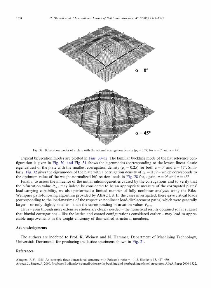
Fig. 32. Bifurcation modes of a plate with the optimal corrugation density (qc = 0.79) for a = 0� and a = 45�.
1534 H. Obrecht et al. / International Journal of Solids and Structures 45 (2008) 1513–1535
Typical bifurcation modes are plotted in Figs. 30–32. The familiar buckling mode of the flat reference con-figuration is given in Fig. 30, and Fig. 31 shows the eigenmodes (corresponding to the lowest linear elasticeigenvalues) of the plate with the smallest corrugation density (qc = 0.25) for both a = 0� and a = 45�. Simi-larly, Fig. 32 gives the eigenmodes of the plate with a corrugation density of qc = 0.79 – which corresponds tothe optimum value of the weight-normalized bifurcation loads in Fig. 28 for, again, a = 0� and a = 45�.
Finally, to assess the influence of the initial inhomogeneities caused by the corrugations and to verify thatthe bifurcation value Pcr,c may indeed be considered to be an appropriate measure of the corrugated plates’load-carrying capability, we also performed a limited number of fully nonlinear analyses using the Riks-Wempner path-following algorithm provided by ABAQUS. In the cases investigated, these gave critical loads(corresponding to the load-maxima of the respective nonlinear load-displacement paths) which were generallylarger – or only slightly smaller – than the corresponding bifurcation values Pcr,c.
Thus – even though more extensive studies are clearly needed – the numerical results obtained so far suggestthat biaxial corrugations – like the lattice and coated configurations considered earlier – may lead to appre-ciable improvements in the weight-efficiency of thin-walled structural members.
Acknowledgements
The authors are indebted to Prof. K. Weinert and N. Hammer, Department of Machining Technology,Universitat Dortmund, for producing the lattice specimens shown in Fig. 21.
References
Almgren, R.F., 1985. An isotropic three dimensional structure with Poisson’s ratio = �1. J. Elasticity 15, 427–430.Arbocz, J., Singer, J., 2000. Professor Budiansky’s contribution to the buckling and postbuckling of shell structures. AIAA-Paper 2000-1322.

H. Obrecht et al. / International Journal of Solids and Structures 45 (2008) 1513–1535 1535
Brush, D.O., Almroth, B.O., 1978. Buckling of Bars, Plates and Shells. McGraw-Hill, New York.Budiansky, B., 1974. Theory of buckling and post-buckling behavior of elastic structures. In: Advances in Applied Mechanics 14, pp. 1–65.Budiansky, B., 1999. On the minimum weights of compression structures. Int. J. Solids Struct. 36, 3677–3708.Budiansky, B., Hutchinson, J.W., 1972. Buckling of circular cylindrical shells under axial compression. Contributions to the Theory of
Aircraft Structures (A. van der Neut Anniversary Volume). Delft University Press, Delft, pp. 239–259.Evans, K.E., Alderson, A., 2000. Auxetic materials: Functional materials and structures from lateral thinking. Adv. Mater. 12, 617–628.Evans, K.E., Alderson, K.L., 2000. Auxetic materials: the positive side of being negative. Eng. Sci. Edu. J., 148–154.Gough, G.S., Elam, C.F., de Bruyne, N.A., 1940. The stabilization of a thin sheet by a continuous supporting medium. J. Roy. Aeron.
Soc. 44, 12–43.Hutchinson, J.W., He, M.Y., 2000. Buckling of circular cylindrical sandwich shells with metal foam cores. Int. J. Solids Struct. 37, 6777–
6794.Hutchinson, J.W., Koiter, W.T., 1970. Postbuckling theory. Appl. Mech. Rev. 23, 1353–1366.Karam, G.N., Gibson, L.J., 1995. Elastic buckling of cylindrical shells with elastic cores. Int. J. Solids Struct. 32, 1259–1306.Koiter, W.T., 1945. Over de stabiliteit van het elastisch evenwicht (On the stability of elastic equilibrium). Thesis, Delft University of
Technology. H.J. Paris, Amsterdam (English translation: NASA TT-F10833, 1967).Koiter, W.T., 1963. On the stability of axisymmetric imperfections on the buckling of cylindrical shells under axial compression. Proc.
Koninkl. Nederl. Akad. Wetenschappen B 66, 265–279.Lakes, R.S., 1992. No contractile obligations. Nature 358, 713–714.Lakes, R.S., 1993. Advances in negative Poisson’s ratio materials. Adv. Mater. 5, 293–296.Levy, R., 1990. Buckling optimization of beams and plates on elastic foundations. ASCE, J. Eng. Mech. 116 (1), 18–34.NASA, 1965. Buckling of thin-walled circular cylinders. NASA SP-8007 (revised in 1968).Obrecht, H., Rosenthal, B., Fuchs, P., Lange, S., Marusczyk, Chr., 2006. Buckling, postbuckling and imperfection-sensitivity: Old
questions and some new answers. Comput. Mech. 37, 498–506.Plaut, R.H., Johnson, L.W., Olhoff, N., 1986. Bimodal optimization of compressed columns on elastic foundation. J. Appl. Mech. 53, 130–
134.Singer, J., Arbocz, J., Weller, T., 1997. Buckling Experiments: Experimental Methods in Buckling of Thin-walled Structures – Vol.1. Basic
Concepts, Columns, Beams and Plates. J. Wiley, New York.Singer, J., Arbocz, J., Weller, T., 2002. Buckling Experiments: Experimental Methods in Buckling of Thin-walled Structures – Vol. 2.
Shells, Built-Up Structures, Composites and Additional Topics. J. Wiley, New York.Thompson, J.M.T., 1972. Optimization as a generator of structural instability. Int. J. Mech. Sci. 14, 627–629.Thompson, J.M.T., Lewis, G.M., 1972. On the optimum design of thin-walled compression members. J. Mech. Phys. Solids 20, 101–109.Thompson, J.M.T., Supple, W.J., 1973. Erosion of optimum designs by compound branching phenomena. J. Mech. Phys. Solids 21, 135–
144.