Embed Size (px)
Citation preview
1
INTRODUCTION TO SYNCHRONIZING
AUTOMATIC SYNCHRONIZINGCONSIDERATIONS AND APPLICATIONS
I. INTRODUCTIONA. DefinitionB. Necessity for Synchronizing
II. TYPES OF SYNCHRONIZINGA. ManualB. Manual with Permissive Relay (Synch check)C. Automatic
III. TYPES OF AUTOMATIC SYNCHRONIZERSA. Phase Lock Type Automatic Synchronizer
a. Frequency/Phase Correction Option b. Voltage Correction Option c. Dead Bus Option
B. Anticipatory Type Automatic Synchronizer a. Frequency Matching b. Boost Pulsing c. Voltage Matching
IV. SYNCHRONIZING CONSIDERATIONSA. Generator Size
a. Small Machines b. Large Machines
V. SUMMARY
2
INTRODUCTION TO SYNCHRONIZING
AUTOMATIC SYNCHRONIZINGCONSIDERATIONS AND APPLICATIONS
INTRODUCTIONIt is the intention of this presentation to provide an explanation of the automatic synchroniz-ing process, to explore the considerations involved and to look at some synchronizingapplications for selection of the proper synchronizer.
DefinitionSynchronizing, in its simplest form, is the process of electrically connecting additionalgenerators to an existing bus.
Necessity for SynchronizingThe necessity for synchronizing and parallel generator operation is often based on thefollowing:
1) The rated generating capacity of an existing system has been exceededby new load demands.
2) Enhanced reliability (multiple generating vs. single unit generating) is tobe considered.
3) Operating efficiency of generator sets is a valid concern.
These additional generators will be connected to operate in parallel with each other andsupply power to the same load. The additional oncoming generators must be synchro-nized properly to ensure:
1) Minimal disturbance to the bus.2) Minimal shock to the generator, mechanical and electrical.3) Rapid loading of the oncoming generator to take on its share.
The synchronizing equipment selected depends on the generating equipment.
To better understand the synchronizing process, let’s examine a typical facility with on-sitepower generation shown in the example of Figure 1.
3
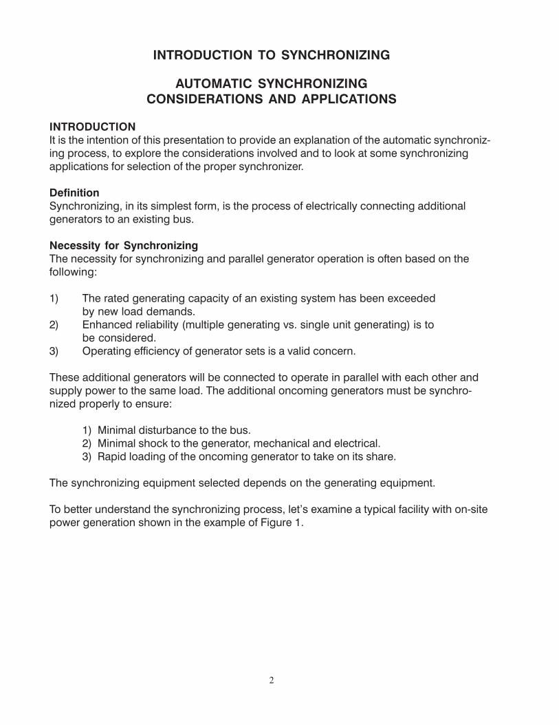
Figure 1: Typical industrial facility with its own on-site generators
Let’s assume that this facility has a critical manufacturing process that cannot tolerate apower failure, or the consequence would be an expensive and lengthy clean-up process.Due to an open circuit breaker as a result of a fault on Utility Feed B, the plant manager hasdecided to start the facility’s own generators and supply the majority of its own powerdemands in the event that Utility Feed A would also trip and would cause their facility tobecome islanded.
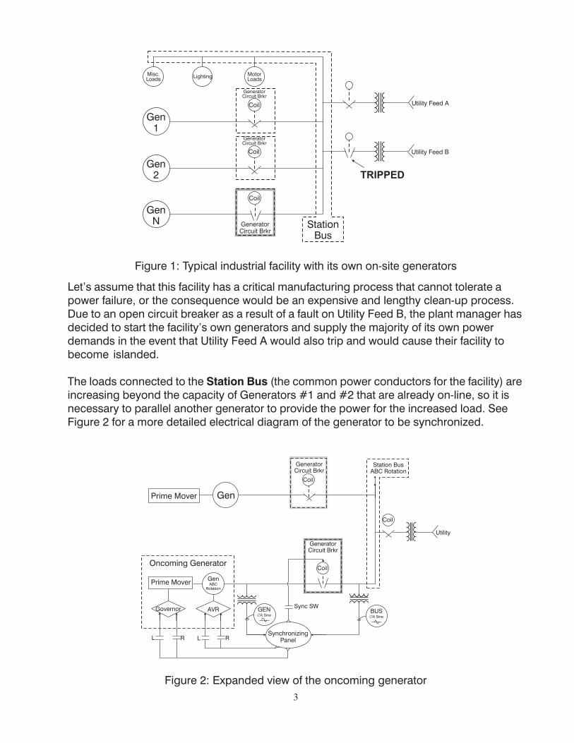
The loads connected to the Station Bus (the common power conductors for the facility) areincreasing beyond the capacity of Generators #1 and #2 that are already on-line, so it isnecessary to parallel another generator to provide the power for the increased load. SeeFigure 2 for a more detailed electrical diagram of the generator to be synchronized.
Figure 2: Expanded view of the oncoming generator
4
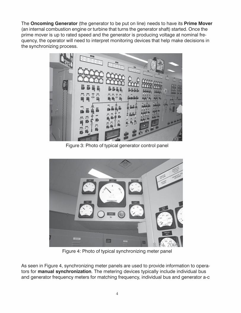
The Oncoming Generator (the generator to be put on line) needs to have its Prime Mover(an internal combustion engine or turbine that turns the generator shaft) started. Once theprime mover is up to rated speed and the generator is producing voltage at nominal fre-quency, the operator will need to interpret monitoring devices that help make decisions inthe synchronizing process.
Figure 3: Photo of typical generator control panel
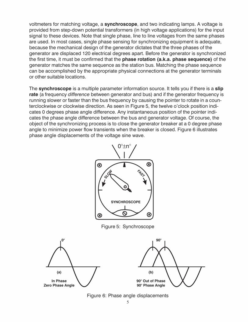
Figure 4: Photo of typical synchronizing meter panel
As seen in Figure 4, synchronizing meter panels are used to provide information to opera-tors for manual synchronization. The metering devices typically include individual busand generator frequency meters for matching frequency, individual bus and generator a-c
5
voltmeters for matching voltage, a synchroscope, and two indicating lamps. A voltage isprovided from step-down potential transformers (in high voltage applications) for the inputsignal to these devices. Note that single phase, line to line voltages from the same phasesare used. In most cases, single phase sensing for synchronizing equipment is adequate,because the mechanical design of the generator dictates that the three phases of thegenerator are displaced 120 electrical degrees apart. Before the generator is synchronizedthe first time, it must be confirmed that the phase rotation (a.k.a. phase sequence) of thegenerator matches the same sequence as the station bus. Matching the phase sequencecan be accomplished by the appropriate physical connections at the generator terminalsor other suitable locations.
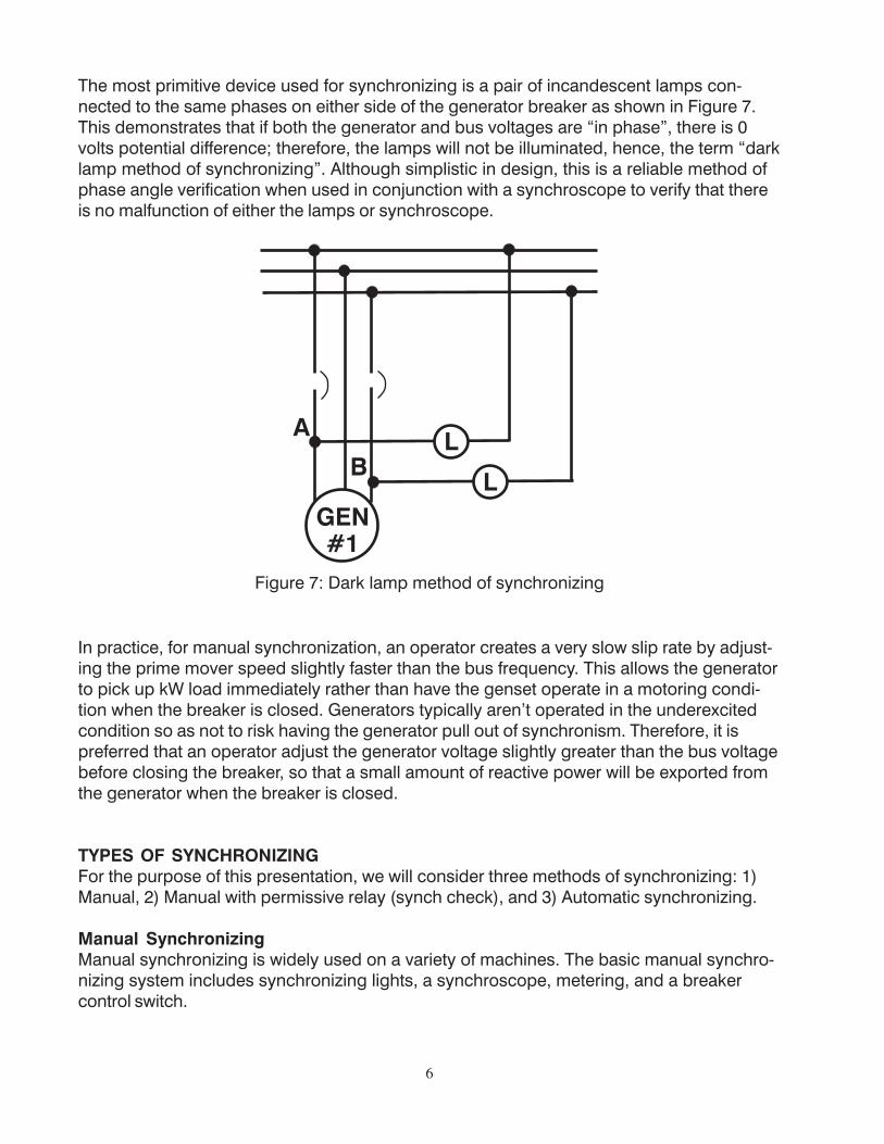
The synchroscope is a multiple parameter information source. It tells you if there is a sliprate (a frequency difference between generator and bus) and if the generator frequency isrunning slower or faster than the bus frequency by causing the pointer to rotate in a coun-terclockwise or clockwise direction. As seen in Figure 5, the twelve o’clock position indi-cates 0 degrees phase angle difference. Any instantaneous position of the pointer indi-cates the phase angle difference between the bus and generator voltage. Of course, theobject of the synchronizing process is to close the generator breaker at a 0 degree phaseangle to minimize power flow transients when the breaker is closed. Figure 6 illustratesphase angle displacements of the voltage sine wave.
Figure 5: Synchroscope
Figure 6: Phase angle displacements
6
The most primitive device used for synchronizing is a pair of incandescent lamps con-nected to the same phases on either side of the generator breaker as shown in Figure 7.This demonstrates that if both the generator and bus voltages are “in phase”, there is 0volts potential difference; therefore, the lamps will not be illuminated, hence, the term “darklamp method of synchronizing”. Although simplistic in design, this is a reliable method ofphase angle verification when used in conjunction with a synchroscope to verify that thereis no malfunction of either the lamps or synchroscope.
Figure 7: Dark lamp method of synchronizing
In practice, for manual synchronization, an operator creates a very slow slip rate by adjust-ing the prime mover speed slightly faster than the bus frequency. This allows the generatorto pick up kW load immediately rather than have the genset operate in a motoring condi-tion when the breaker is closed. Generators typically aren’t operated in the underexcitedcondition so as not to risk having the generator pull out of synchronism. Therefore, it ispreferred that an operator adjust the generator voltage slightly greater than the bus voltagebefore closing the breaker, so that a small amount of reactive power will be exported fromthe generator when the breaker is closed.
TYPES OF SYNCHRONIZINGFor the purpose of this presentation, we will consider three methods of synchronizing: 1)Manual, 2) Manual with permissive relay (synch check), and 3) Automatic synchronizing.
Manual SynchronizingManual synchronizing is widely used on a variety of machines. The basic manual synchro-nizing system includes synchronizing lights, a synchroscope, metering, and a breakercontrol switch.
7
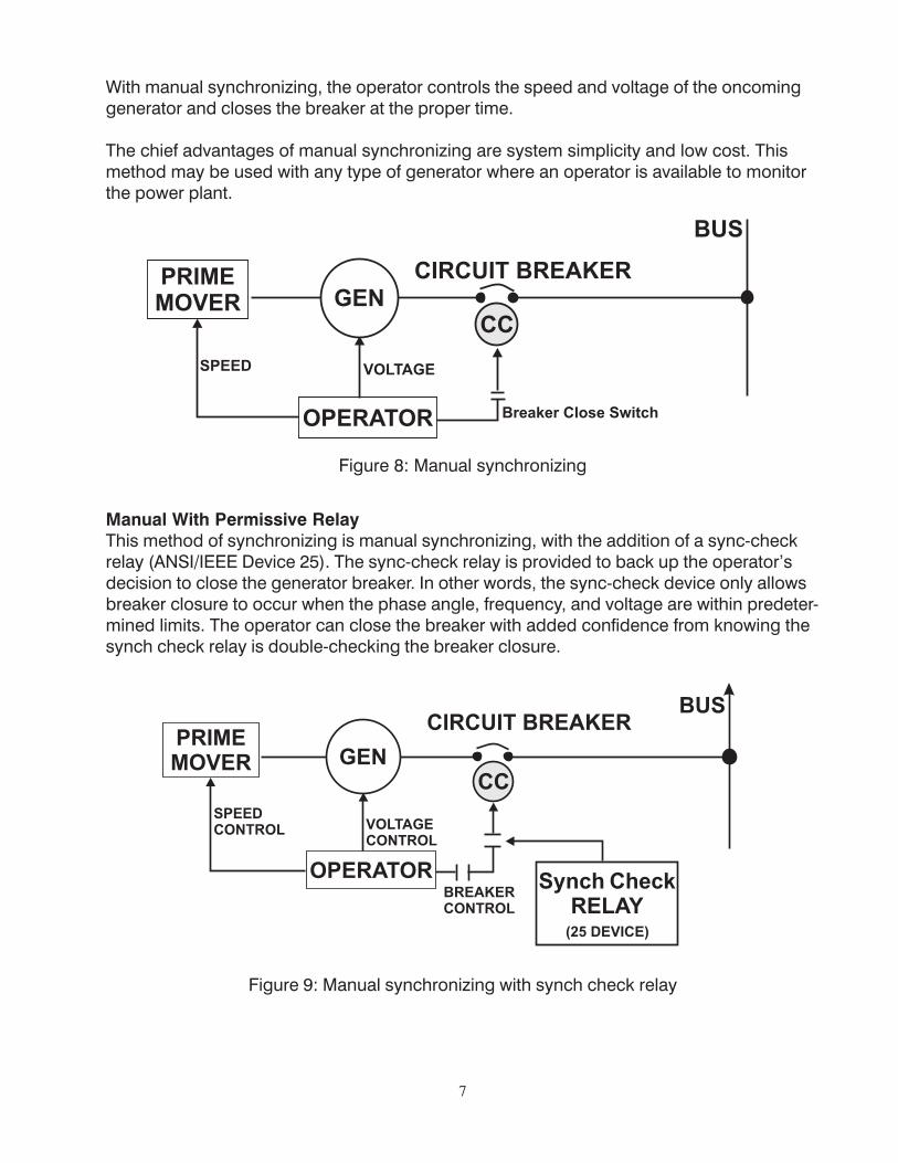
With manual synchronizing, the operator controls the speed and voltage of the oncominggenerator and closes the breaker at the proper time.
The chief advantages of manual synchronizing are system simplicity and low cost. Thismethod may be used with any type of generator where an operator is available to monitorthe power plant.
Figure 8: Manual synchronizing
Manual With Permissive RelayThis method of synchronizing is manual synchronizing, with the addition of a sync-checkrelay (ANSI/IEEE Device 25). The sync-check relay is provided to back up the operator’sdecision to close the generator breaker. In other words, the sync-check device only allowsbreaker closure to occur when the phase angle, frequency, and voltage are within predeter-mined limits. The operator can close the breaker with added confidence from knowing thesynch check relay is double-checking the breaker closure.
Figure 9: Manual synchronizing with synch check relay
8
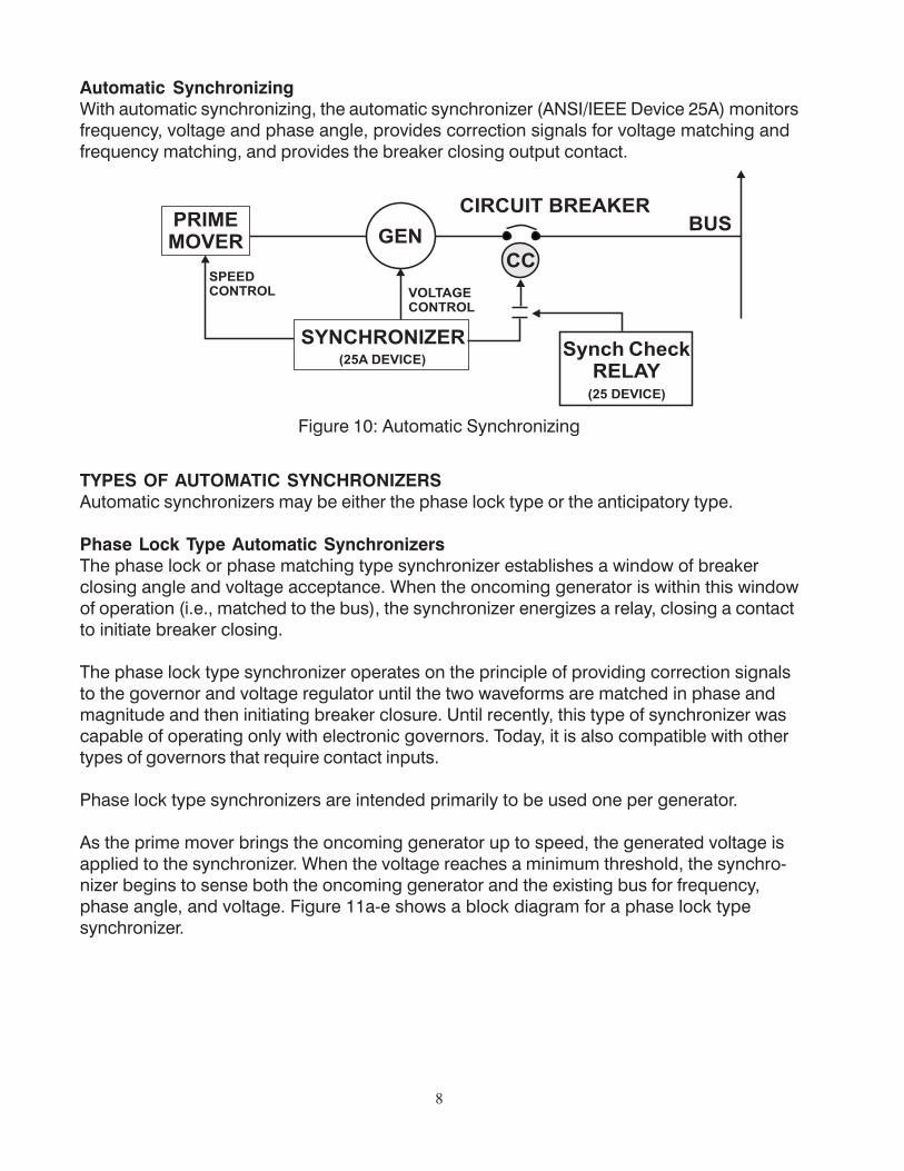
Automatic SynchronizingWith automatic synchronizing, the automatic synchronizer (ANSI/IEEE Device 25A) monitorsfrequency, voltage and phase angle, provides correction signals for voltage matching andfrequency matching, and provides the breaker closing output contact.
Figure 10: Automatic Synchronizing
TYPES OF AUTOMATIC SYNCHRONIZERSAutomatic synchronizers may be either the phase lock type or the anticipatory type.
Phase Lock Type Automatic SynchronizersThe phase lock or phase matching type synchronizer establishes a window of breakerclosing angle and voltage acceptance. When the oncoming generator is within this windowof operation (i.e., matched to the bus), the synchronizer energizes a relay, closing a contactto initiate breaker closing.
The phase lock type synchronizer operates on the principle of providing correction signalsto the governor and voltage regulator until the two waveforms are matched in phase andmagnitude and then initiating breaker closure. Until recently, this type of synchronizer wascapable of operating only with electronic governors. Today, it is also compatible with othertypes of governors that require contact inputs.
Phase lock type synchronizers are intended primarily to be used one per generator.
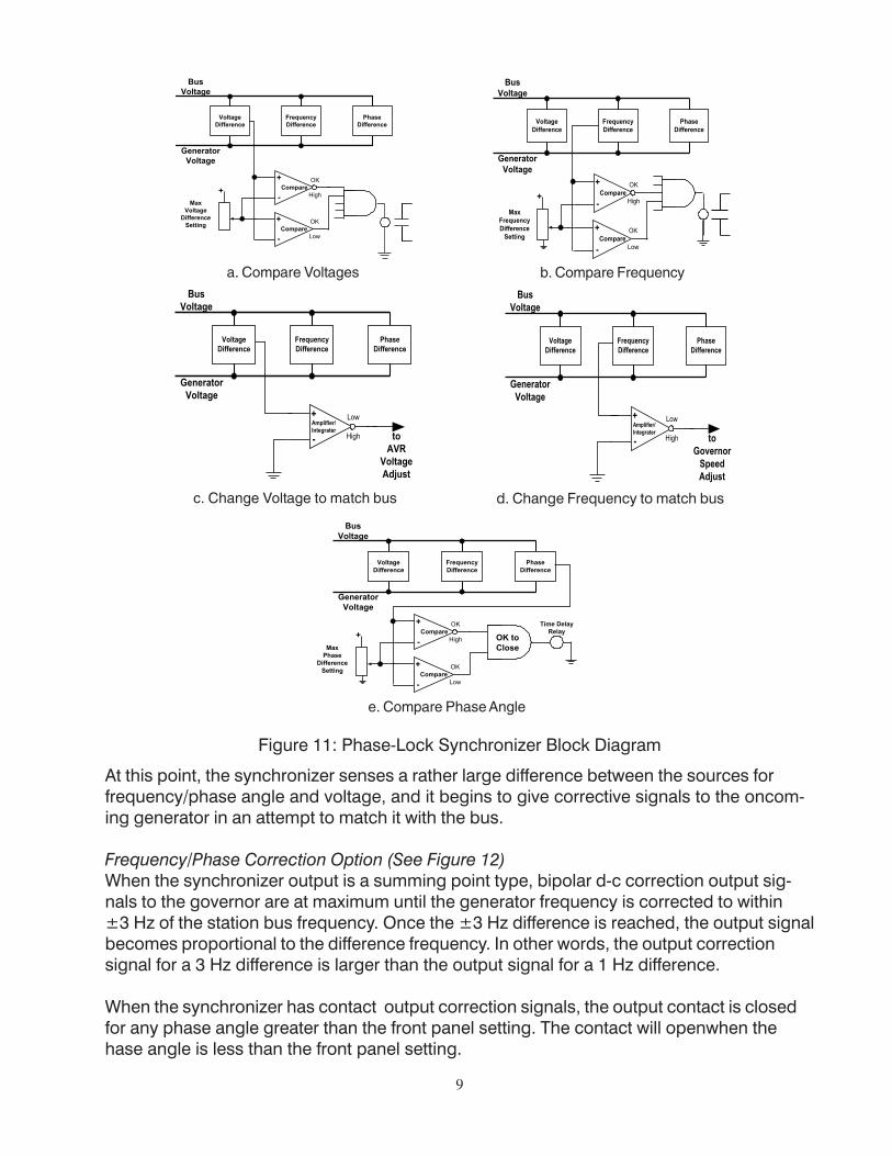
As the prime mover brings the oncoming generator up to speed, the generated voltage isapplied to the synchronizer. When the voltage reaches a minimum threshold, the synchro-nizer begins to sense both the oncoming generator and the existing bus for frequency,phase angle, and voltage. Figure 11a-e shows a block diagram for a phase lock typesynchronizer.
9
a. Compare Voltages b. Compare Frequency
c. Change Voltage to match bus d. Change Frequency to match bus
e. Compare Phase Angle
At this point, the synchronizer senses a rather large difference between the sources forfrequency/phase angle and voltage, and it begins to give corrective signals to the oncom-ing generator in an attempt to match it with the bus.
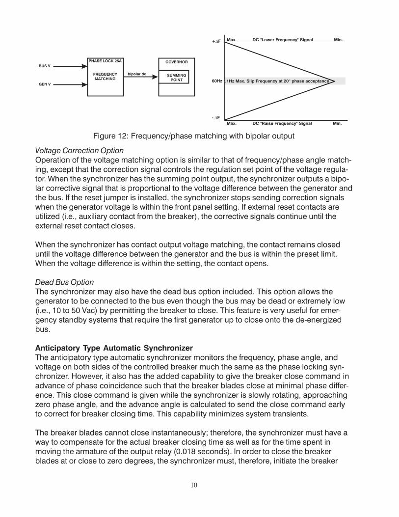
Frequency/Phase Correction Option (See Figure 12)When the synchronizer output is a summing point type, bipolar d-c correction output sig-nals to the governor are at maximum until the generator frequency is corrected to within±3 Hz of the station bus frequency. Once the ±3 Hz difference is reached, the output signalbecomes proportional to the difference frequency. In other words, the output correctionsignal for a 3 Hz difference is larger than the output signal for a 1 Hz difference.
When the synchronizer has contact output correction signals, the output contact is closedfor any phase angle greater than the front panel setting. The contact will openwhen thehase angle is less than the front panel setting.
Figure 11: Phase-Lock Synchronizer Block Diagram
10
Figure 12: Frequency/phase matching with bipolar output
Voltage Correction OptionOperation of the voltage matching option is similar to that of frequency/phase angle match-ing, except that the correction signal controls the regulation set point of the voltage regula-tor. When the synchronizer has the summing point output, the synchronizer outputs a bipo-lar corrective signal that is proportional to the voltage difference between the generator andthe bus. If the reset jumper is installed, the synchronizer stops sending correction signalswhen the generator voltage is within the front panel setting. If external reset contacts areutilized (i.e., auxiliary contact from the breaker), the corrective signals continue until theexternal reset contact closes.
When the synchronizer has contact output voltage matching, the contact remains closeduntil the voltage difference between the generator and the bus is within the preset limit.When the voltage difference is within the setting, the contact opens.
Dead Bus OptionThe synchronizer may also have the dead bus option included. This option allows thegenerator to be connected to the bus even though the bus may be dead or extremely low(i.e., 10 to 50 Vac) by permitting the breaker to close. This feature is very useful for emer-gency standby systems that require the first generator up to close onto the de-energizedbus.
Anticipatory Type Automatic SynchronizerThe anticipatory type automatic synchronizer monitors the frequency, phase angle, andvoltage on both sides of the controlled breaker much the same as the phase locking syn-chronizer. However, it also has the added capability to give the breaker close command inadvance of phase coincidence such that the breaker blades close at minimal phase differ-ence. This close command is given while the synchronizer is slowly rotating, approachingzero phase angle, and the advance angle is calculated to send the close command earlyto correct for breaker closing time. This capability minimizes system transients.
The breaker blades cannot close instantaneously; therefore, the synchronizer must have away to compensate for the actual breaker closing time as well as for the time spent inmoving the armature of the output relay (0.018 seconds). In order to close the breakerblades at or close to zero degrees, the synchronizer must, therefore, initiate the breaker
11
close signal in advance of the synchronism point. In other words, it must “anticipate” theactual point of synchronism.
The anticipatory type synchronizer calculates the advanced angle that is required to com-pensate for the breaker closure time by monitoring the slip frequency (frequency differencebetween the oncoming generator and the bus) and the set in value for breaker closing. Italso factors in the constant of the armature movement (0.018 seconds) to complete thecalculation. The calculation relationship is:
= 360 (T + T ) F
where
A = the advance angle, which is the electrical phase angle of the generator withrespect to the system bus when the synchronizer initiates closure of thecontrolled circuit breaker.
TB = the circuit breaker closing time. This is the time between the initial application ofthe electrical stimulus to the closing circuitry and the actual contact of the breakerpoles. This is considered to be a constant by the automatic synchronizer.
TR = the response time of the output relay, which is approximately 0.018 seconds.FS = the slip frequency, i.e., the difference between the oncoming generator frequency
and the system bus frequency.
Anticipatory Type Synchronizer System OperationIn the synchronizing process, the machine is started and the synchronizer is initiated as themachine comes up to speed. The slip frequency is initially greater than that allowable bythe slip frequency control setting. But as the machine accelerates and approaches thesystem frequency, an automatic synchronizing system with speed and voltage matchingcapabilities will make the adjustments required to match the machine’s speed to thesystem frequency by stimulating the governor controls. The voltage monitoring portion ofthe automatic synchronizer system will attempt to adjust the voltage regulator to bring themachine’s terminal voltage within the tolerances set on to the synchronizer’s front panelcontrols. When the voltage difference between the machine terminals and the system busis within the limits established on the automatic synchronizer and the slip frequency iswithin the predetermined limits, corrections made by the synchronizing system will cease.The synchronizer then will calculate the advance angle required to close the breakerblades for a zero degree phase difference based on the programmed breaker closure timeand the actual slip frequency existing at that point in time. Note that in order for the syn-chronizer to function properly, there must be a small slip frequency between the systemand the generator in order to make the proper calculation.
A B R S
12
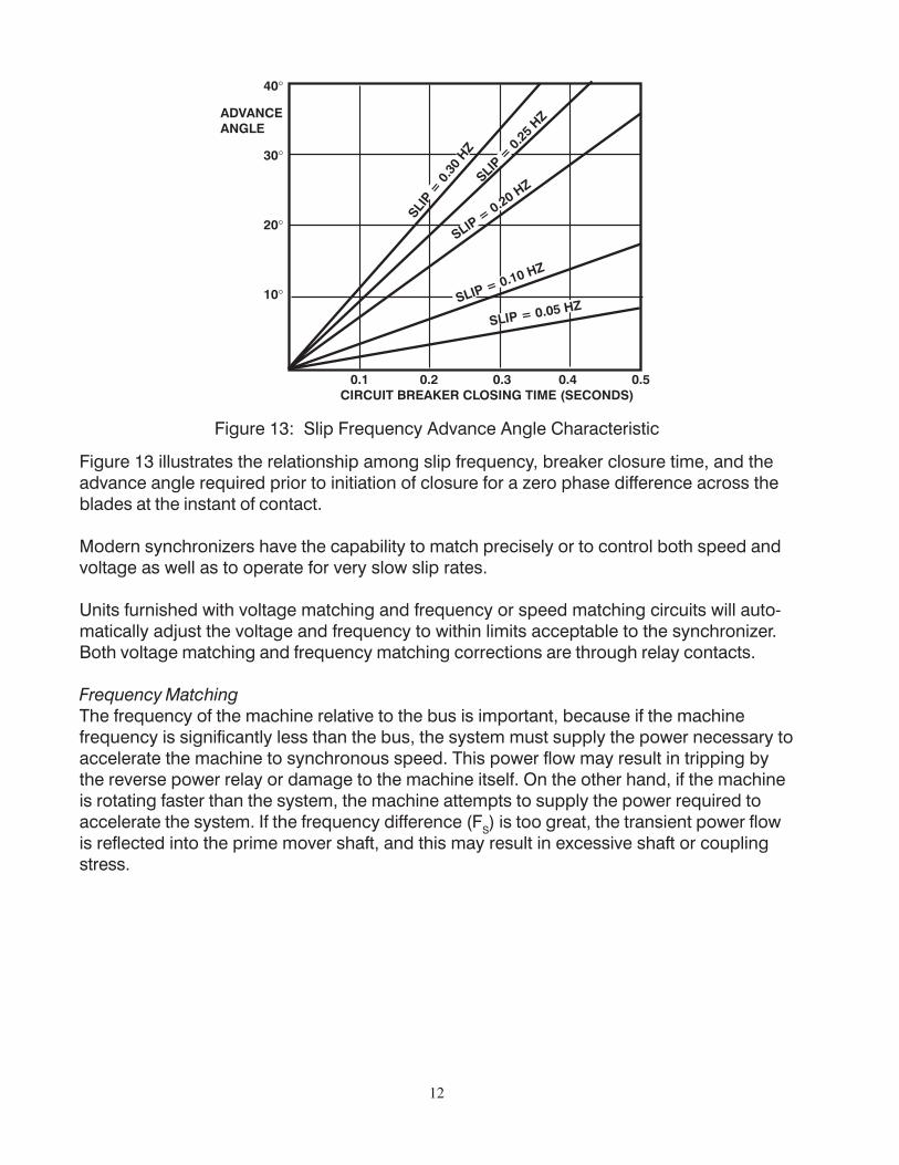
Figure 13: Slip Frequency Advance Angle Characteristic
Figure 13 illustrates the relationship among slip frequency, breaker closure time, and theadvance angle required prior to initiation of closure for a zero phase difference across theblades at the instant of contact.
Modern synchronizers have the capability to match precisely or to control both speed andvoltage as well as to operate for very slow slip rates.
Units furnished with voltage matching and frequency or speed matching circuits will auto-matically adjust the voltage and frequency to within limits acceptable to the synchronizer.Both voltage matching and frequency matching corrections are through relay contacts.
Frequency MatchingThe frequency of the machine relative to the bus is important, because if the machinefrequency is significantly less than the bus, the system must supply the power necessary toaccelerate the machine to synchronous speed. This power flow may result in tripping bythe reverse power relay or damage to the machine itself. On the other hand, if the machineis rotating faster than the system, the machine attempts to supply the power required toaccelerate the system. If the frequency difference (FS) is too great, the transient power flowis reflected into the prime mover shaft, and this may result in excessive shaft or couplingstress.
13
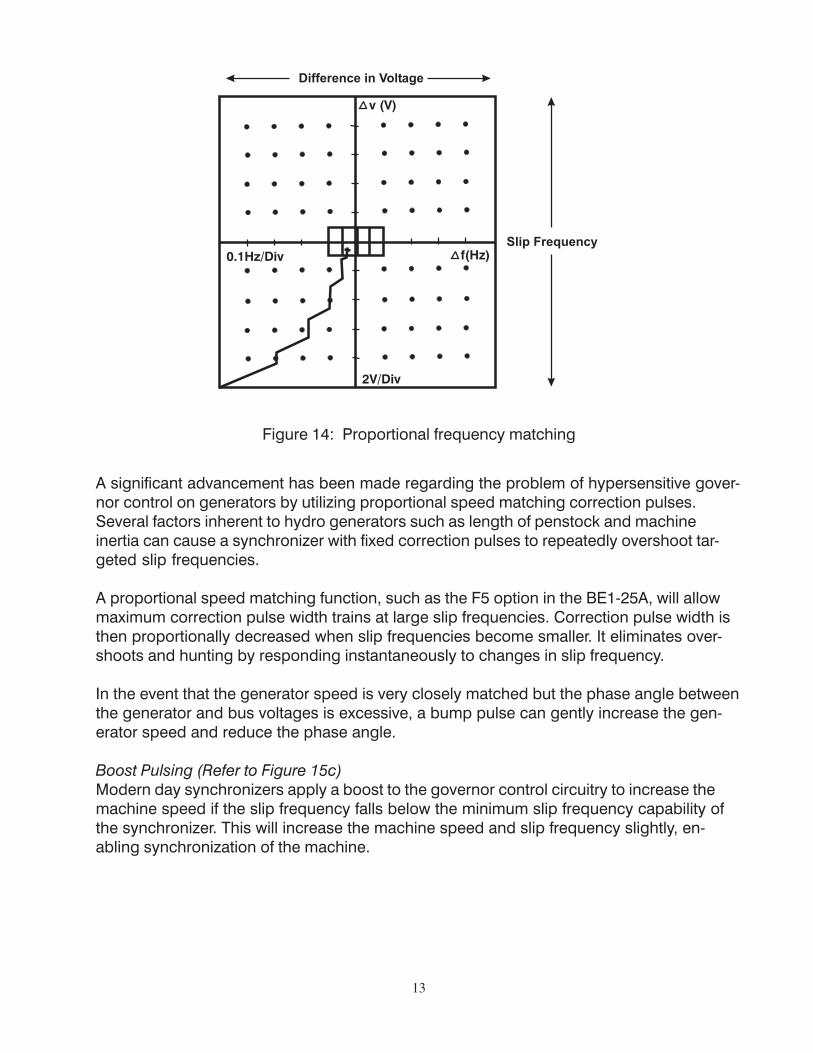
Figure 14: Proportional frequency matching
A significant advancement has been made regarding the problem of hypersensitive gover-nor control on generators by utilizing proportional speed matching correction pulses.Several factors inherent to hydro generators such as length of penstock and machineinertia can cause a synchronizer with fixed correction pulses to repeatedly overshoot tar-geted slip frequencies.
A proportional speed matching function, such as the F5 option in the BE1-25A, will allowmaximum correction pulse width trains at large slip frequencies. Correction pulse width isthen proportionally decreased when slip frequencies become smaller. It eliminates over-shoots and hunting by responding instantaneously to changes in slip frequency.
In the event that the generator speed is very closely matched but the phase angle betweenthe generator and bus voltages is excessive, a bump pulse can gently increase the gen-erator speed and reduce the phase angle.
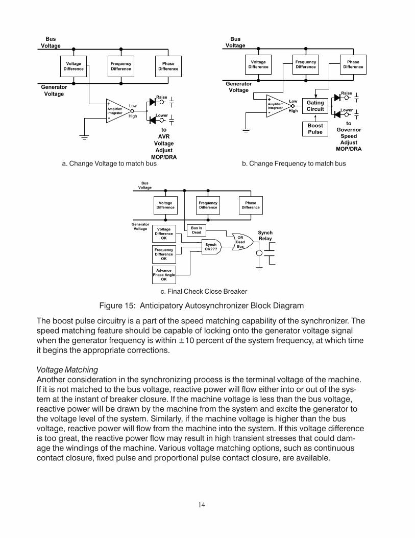
Boost Pulsing (Refer to Figure 15c)Modern day synchronizers apply a boost to the governor control circuitry to increase themachine speed if the slip frequency falls below the minimum slip frequency capability ofthe synchronizer. This will increase the machine speed and slip frequency slightly, en-abling synchronization of the machine.
14
Figure 15: Anticipatory Autosynchronizer Block Diagram
The boost pulse circuitry is a part of the speed matching capability of the synchronizer. Thespeed matching feature should be capable of locking onto the generator voltage signalwhen the generator frequency is within ±10 percent of the system frequency, at which timeit begins the appropriate corrections.
Voltage MatchingAnother consideration in the synchronizing process is the terminal voltage of the machine.If it is not matched to the bus voltage, reactive power will flow either into or out of the sys-tem at the instant of breaker closure. If the machine voltage is less than the bus voltage,reactive power will be drawn by the machine from the system and excite the generator tothe voltage level of the system. Similarly, if the machine voltage is higher than the busvoltage, reactive power will flow from the machine into the system. If this voltage differenceis too great, the reactive power flow may result in high transient stresses that could dam-age the windings of the machine. Various voltage matching options, such as continuouscontact closure, fixed pulse and proportional pulse contact closure, are available.
a. Change Voltage to match bus b. Change Frequency to match bus
c. Final Check Close Breaker
15
SYNCHRONIZING CONSIDERATIONS
Generator SizeFor power to flow out of the machine and into the system at the time the breaker contactsclose, it is desirable for larger machines’ speed to be slightly greater than the system priorto synchronizing. Therefore, the synchronizer must be capable of determining that themachine frequency is greater than the system frequency (i.e., that the slip rate is positive).However, with small machines, it may be acceptable to initiate closure of the generatorbreaker while the machine is slightly slower than the system, providing that the synchro-nizer parameters are within the preset limits and the machine is accelerating and capableof accepting load.
For this paper’s intent, we will refer to small machines as those machines used for emer-gency and standby operations and to large machines as those used solely for stationarypower plants.
Small MachinesThe need for generator sets as standby power is crucial for the operation of many facilities.For example, an airport facility requires several engine generator sets to maintain continu-ity of service during emergency conditions or to supply specific load requirements duringpeak demand periods. The load demands expected at an airport complex exceed thegenerating capability of one generator and require additional generators to be connectedto the station bus.
Manual synchronizing could be performed by power plant operating personnel. The oper-ating personnel would manually adjust the frequency and voltage of the generator to beparalleled and would ultimately close the circuit breaker to tie the generator to the loadbus. This type of synchronizing scheme is quite simple and most economical. However,the one drawback is that it requires skilled operators at the controls to avoid costly damageto equipment due to improper synchronizing.
The addition of a supervisory relay to the manual synchronization process assists withproper synchronization. Manual synchronization with a supervisory relay still requires theoperator to manually control voltage and frequency, but the supervisory relay sets up anoperating tolerance that must be equaled before the circuit breaker can be closed to paral-lel the alternator.
The supervisory relay compares the slip frequency, phase angle, and voltage differencesbetween the oncoming generator and the station bus. These parameters and some typicalranges are listed below. The supervisory relay does not close its output contacts until allsystem parameters are satisfied.
Parameters RangeSlip Frequency 0.1 HertzPhase Angle 0° to 30° (adjustment)Voltage 4 volts
16
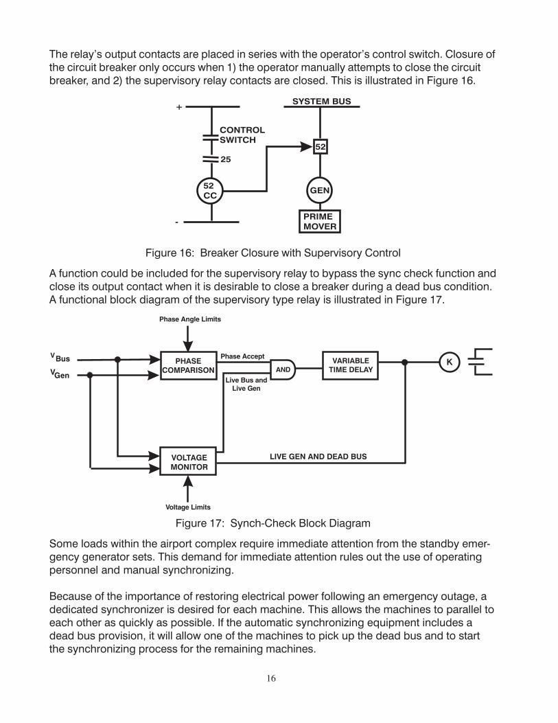
The relay’s output contacts are placed in series with the operator’s control switch. Closure ofthe circuit breaker only occurs when 1) the operator manually attempts to close the circuitbreaker, and 2) the supervisory relay contacts are closed. This is illustrated in Figure 16.
Figure 16: Breaker Closure with Supervisory Control
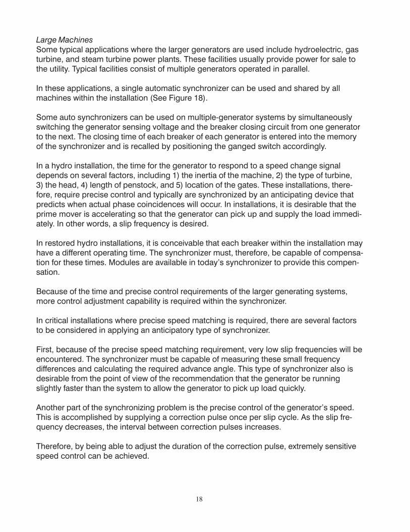
A function could be included for the supervisory relay to bypass the sync check function andclose its output contact when it is desirable to close a breaker during a dead bus condition.A functional block diagram of the supervisory type relay is illustrated in Figure 17.
Figure 17: Synch-Check Block Diagram
Some loads within the airport complex require immediate attention from the standby emer-gency generator sets. This demand for immediate attention rules out the use of operatingpersonnel and manual synchronizing.
Because of the importance of restoring electrical power following an emergency outage, adedicated synchronizer is desired for each machine. This allows the machines to parallel toeach other as quickly as possible. If the automatic synchronizing equipment includes adead bus provision, it will allow one of the machines to pick up the dead bus and to startthe synchronizing process for the remaining machines.
17
For this application, we could use the anticipatory type synchronizer discussed earlier.However, this type of device is expensive to apply to a number of machines on a dedi-cated basis. A sequencing circuit could be used to switch the anticipatory device from onemachine to another, but this adds time to the restoration of system power and complexity tothe overall control circuitry which might not be desirable in this application. So for thisparticular job, we would use the phase lock type automatic synchronizer.
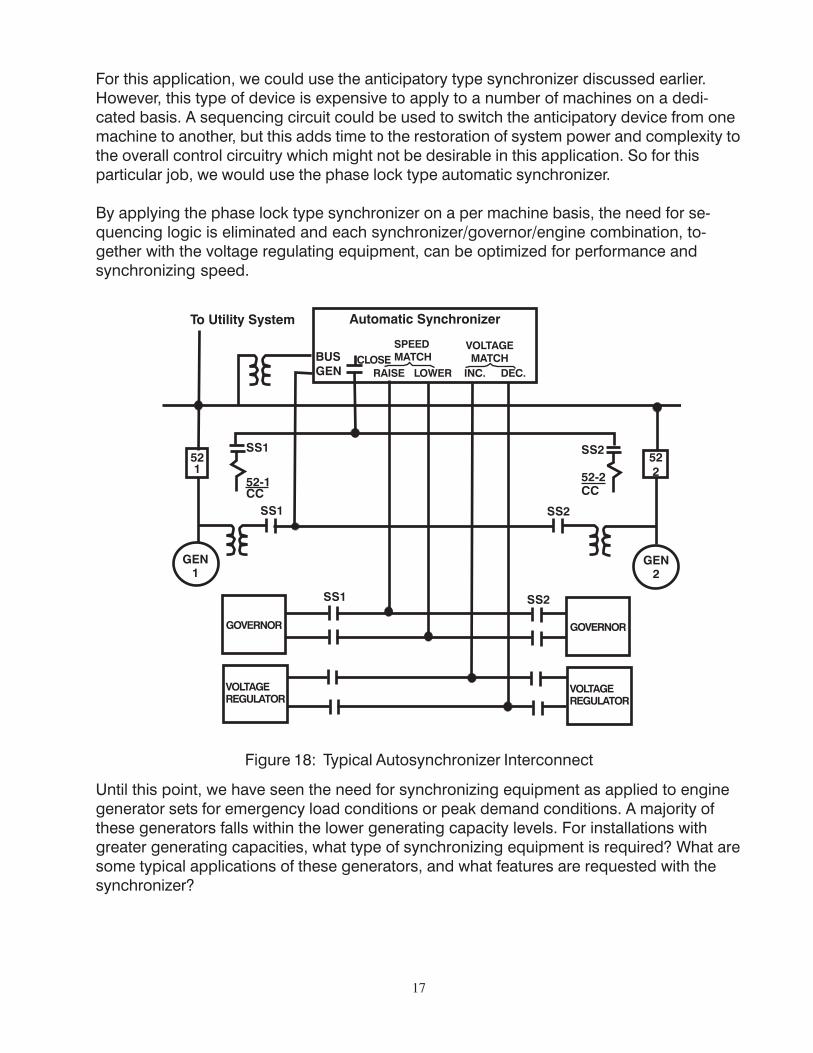
By applying the phase lock type synchronizer on a per machine basis, the need for se-quencing logic is eliminated and each synchronizer/governor/engine combination, to-gether with the voltage regulating equipment, can be optimized for performance andsynchronizing speed.
Figure 18: Typical Autosynchronizer Interconnect
Until this point, we have seen the need for synchronizing equipment as applied to enginegenerator sets for emergency load conditions or peak demand conditions. A majority ofthese generators falls within the lower generating capacity levels. For installations withgreater generating capacities, what type of synchronizing equipment is required? What aresome typical applications of these generators, and what features are requested with thesynchronizer?
18
Large MachinesSome typical applications where the larger generators are used include hydroelectric, gasturbine, and steam turbine power plants. These facilities usually provide power for sale tothe utility. Typical facilities consist of multiple generators operated in parallel.
In these applications, a single automatic synchronizer can be used and shared by allmachines within the installation (See Figure 18).
Some auto synchronizers can be used on multiple-generator systems by simultaneouslyswitching the generator sensing voltage and the breaker closing circuit from one generatorto the next. The closing time of each breaker of each generator is entered into the memoryof the synchronizer and is recalled by positioning the ganged switch accordingly.
In a hydro installation, the time for the generator to respond to a speed change signaldepends on several factors, including 1) the inertia of the machine, 2) the type of turbine,3) the head, 4) length of penstock, and 5) location of the gates. These installations, there-fore, require precise control and typically are synchronized by an anticipating device thatpredicts when actual phase coincidences will occur. In installations, it is desirable that theprime mover is accelerating so that the generator can pick up and supply the load immedi-ately. In other words, a slip frequency is desired.
In restored hydro installations, it is conceivable that each breaker within the installation mayhave a different operating time. The synchronizer must, therefore, be capable of compensa-tion for these times. Modules are available in today’s synchronizer to provide this compen-sation.
Because of the time and precise control requirements of the larger generating systems,more control adjustment capability is required within the synchronizer.
In critical installations where precise speed matching is required, there are several factorsto be considered in applying an anticipatory type of synchronizer.
First, because of the precise speed matching requirement, very low slip frequencies will beencountered. The synchronizer must be capable of measuring these small frequencydifferences and calculating the required advance angle. This type of synchronizer also isdesirable from the point of view of the recommendation that the generator be runningslightly faster than the system to allow the generator to pick up load quickly.
Another part of the synchronizing problem is the precise control of the generator’s speed.This is accomplished by supplying a correction pulse once per slip cycle. As the slip fre-quency decreases, the interval between correction pulses increases.
Therefore, by being able to adjust the duration of the correction pulse, extremely sensitivespeed control can be achieved.

19
SUMMARYWe have looked at the automatic synchronizing process and explored some of the consid-erations involved. We have also evaluated some applications for automatic synchronizingand have seen that there are many different factors that make up the application. Throughthis process, we have tried to establish some guidelines for the selection of the propersynchronizing system for the application.

If you have any questions or needadditional information, please contact
Basler Electric Company.Our web site is located at:
http://www.basler.come-mail: [email protected]
Route 143, Box 269, Highland, Illinois U.S.A. 62249Tel +1 618.654.2341 Fax +1 618.654.2351
e-mail: [email protected]
1300 North Zhongshan Road,Wujiang Economic Development Zone
Suzhou, Jiangsu Province, PRC 215200Tel +86(0)512 6346 1730Fax +86(0)512 6346 1760
e-mail: [email protected]. Les Pins, 67319 Wasselonne Cedex FRANCE
Tel +33 3.88.87.1010 Fax +33 3.88.87.0808e-mail: [email protected]