Embed Size (px)
Citation preview
2C
TIMING, SYNCHRONIZING & ADJUSTING
90-878079 JANUARY 2000 Page 2C-1
ELECTRICALSection 2C - Timing, Synchronizing & Adjusting
Table of Contents
Specifications 2C-1. . . . . . . . . . . . . . . . . . . . . . . . . . . Special Tools 2C-3. . . . . . . . . . . . . . . . . . . . . . . . . . . Adjustments 2C-4. . . . . . . . . . . . . . . . . . . . . . . . . . . .
Carburetor Models 2C-4. . . . . . . . . . . . . . . . . . . . Adjustments 2C-10. . . . . . . . . . . . . . . . . . . . . . . . . . . .
Electronic Fuel Injection Models 2C-10. . . . . . . .
Specifications
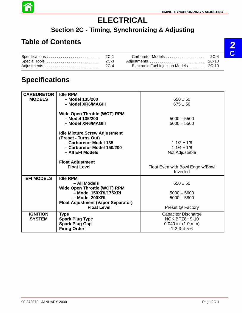
CARBURETORMODELS
Idle RPM– Model 135/200– Model XR6/MAGIII
Wide Open Throttle (WOT) RPM– Model 135/200– Model XR6/MAGIII
Idle Mixture Screw Adjustment(Preset - Turns Out)
– Carburetor Model 135– Carburetor Model 150/200– All EFI Models
Float AdjustmentFloat Level
650 ± 50675 ± 50
5000 – 55005000 – 5500
1-1/2 ± 1/81-1/4 ± 1/8
Not Adjustable
Float Even with Bowl Edge w/BowlInverted
EFI MODELS Idle RPM– All Models
Wide Open Throttle (WOT) RPM– Model 150XRI/175XRI– Model 200XRI
Float Adjustment ( Vapor Separator)Float Level
650 ± 50
5000 – 56005000 – 5800
Preset @ Factory
IGNITIONSYSTEM
TypeSpark Plug Type Spark Plug GapFiring Order
Capacitor DischargeNGK BPZ8HS-100.040 in. (1.0 mm)
1-2-3-4-5-6
MAINTENANCE
Page 2C-2 90-878079 JANUARY 2000
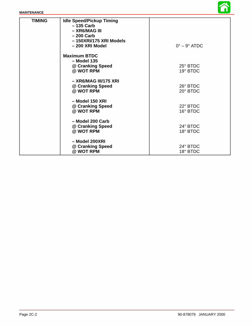
TIMING Idle Speed/Pickup Timing– 135 Carb– XR6/MAG III– 200 Carb– 150XRI/175 XRI Models– 200 XRI Model
Maximum BTDC– Model 135@ Cranking Speed@ WOT RPM
– XR6/MAG III/175 XRI@ Cranking Speed@ WOT RPM
– Model 150 XRI@ Cranking Speed@ WOT RPM
– Model 200 Carb@ Cranking Speed@ WOT RPM
– Model 200XRI@ Cranking Speed@ WOT RPM
0° – 9° ATDC
25° BTDC19° BTDC
26° BTDC20° BTDC
22° BTDC16° BTDC
24° BTDC18° BTDC
24° BTDC18° BTDC
TIMING, SYNCHRONIZING & ADJUSTING
90-878079 JANUARY 2000 Page 2C-3
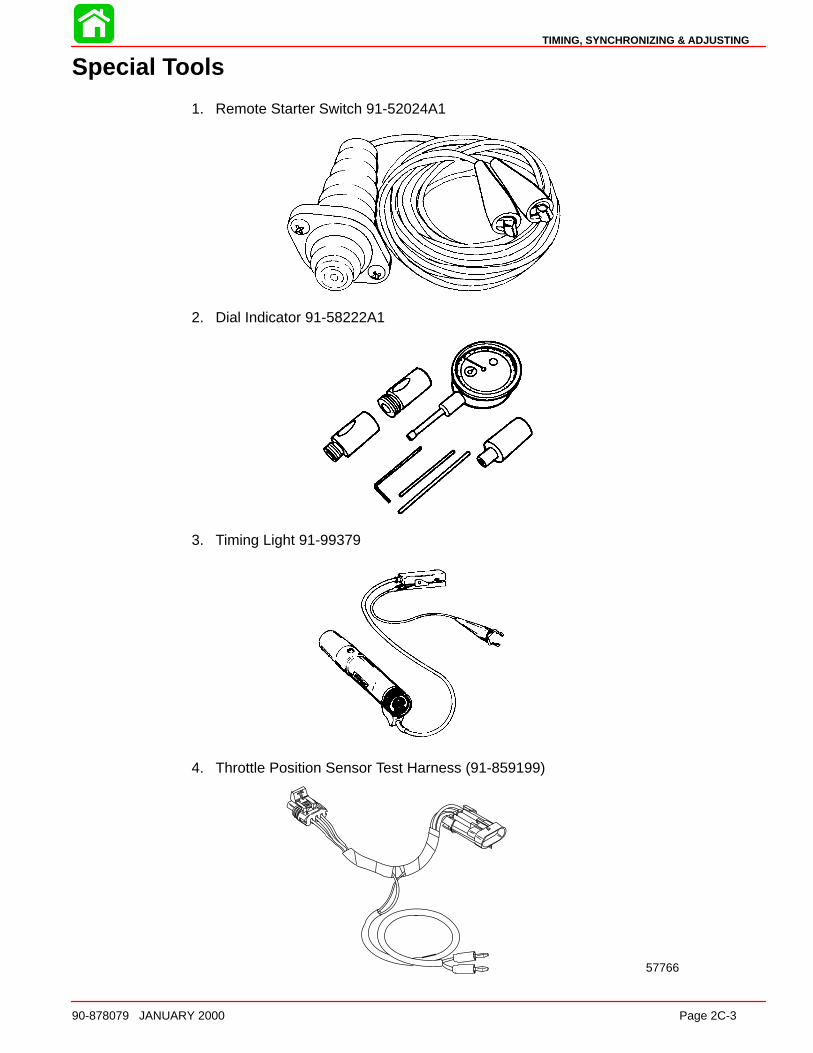
Special Tools
1. Remote Starter Switch 91-52024A1
2. Dial Indicator 91-58222A1
3. Timing Light 91-99379
4. Throttle Position Sensor Test Harness (91-859199)
57766
MAINTENANCE
Page 2C-4 90-878079 JANUARY 2000
Adjustments
Carburetor ModelsTIMING POINTER ADJUSTMENT
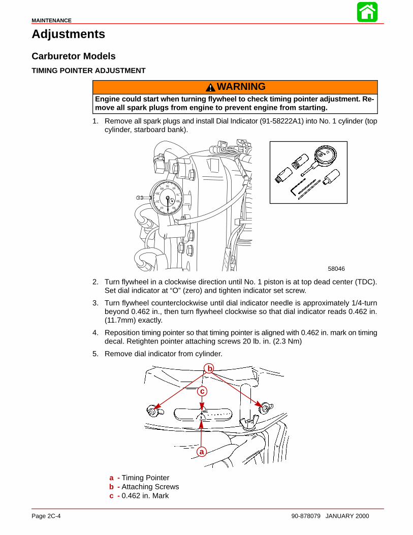
WARNINGEngine could start when turning flywheel to check timing pointer adjustment. Re-move all spark plugs from engine to prevent engine from starting.
1. Remove all spark plugs and install Dial Indicator (91-58222A1) into No. 1 cylinder (topcylinder, starboard bank).
58046
2. Turn flywheel in a clockwise direction until No. 1 piston is at top dead center (TDC).Set dial indicator at “O” (zero) and tighten indicator set screw.
3. Turn flywheel counterclockwise until dial indicator needle is approximately 1/4-turnbeyond 0.462 in., then turn flywheel clockwise so that dial indicator reads 0.462 in.(11.7mm) exactly.
4. Reposition timing pointer so that timing pointer is aligned with 0.462 in. mark on timingdecal. Retighten pointer attaching screws 20 lb. in. (2.3 Nm)
5. Remove dial indicator from cylinder.
b
a
c
a - Timing Pointerb - Attaching Screwsc - 0.462 in. Mark
TIMING, SYNCHRONIZING & ADJUSTING
90-878079 JANUARY 2000 Page 2C-5
CARBURETOR SYNCHRONIZATION
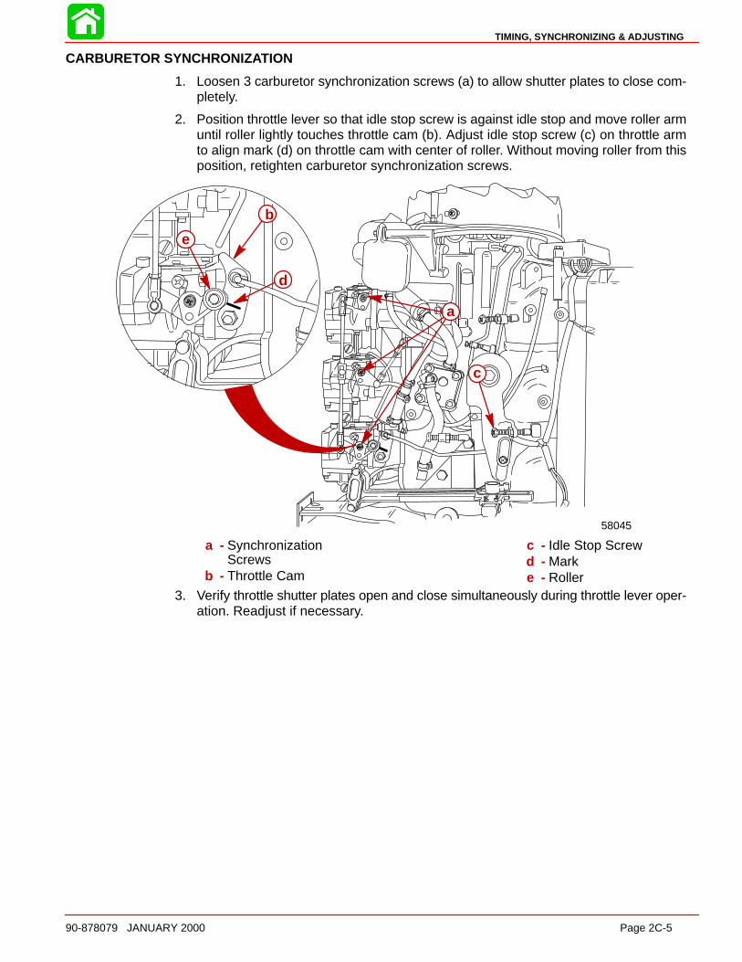
1. Loosen 3 carburetor synchronization screws (a) to allow shutter plates to close com-pletely.
2. Position throttle lever so that idle stop screw is against idle stop and move roller armuntil roller lightly touches throttle cam (b). Adjust idle stop screw (c) on throttle armto align mark (d) on throttle cam with center of roller. Without moving roller from thisposition, retighten carburetor synchronization screws.
58045
a
c
b
d
e
a - SynchronizationScrews
b - Throttle Cam
c - Idle Stop Screwd - Marke - Roller
3. Verify throttle shutter plates open and close simultaneously during throttle lever oper-ation. Readjust if necessary.
MAINTENANCE
Page 2C-6 90-878079 JANUARY 2000
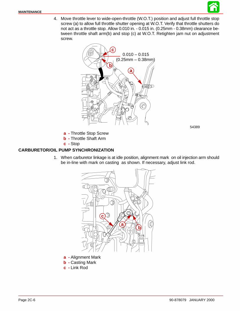
4. Move throttle lever to wide-open-throttle (W.O.T.) position and adjust full throttle stopscrew (a) to allow full throttle shutter opening at W.O.T. Verify that throttle shutters donot act as a throttle stop. Allow 0.010 in. - 0.015 in. (0.25mm - 0.38mm) clearance be-tween throttle shaft arm(b) and stop (c) at W.O.T. Retighten jam nut on adjustmentscrew.
0.010 – 0.015(0.25mm – 0.38mm)
54389
b
c
a
a - Throttle Stop Screwb - Throttle Shaft Armc - Stop
CARBURETOR/OIL PUMP SYNCHRONIZATION
1. When carburetor linkage is at idle position, alignment mark on oil injection arm shouldbe in-line with mark on casting as shown. If necessary, adjust link rod.
ba
c
a - Alignment Markb - Casting Markc - Link Rod
TIMING, SYNCHRONIZING & ADJUSTING
90-878079 JANUARY 2000 Page 2C-7
TIMING ADJUSTMENTS
CAUTIONEngine may be timed while cranking engine with starter moto r. To prevent enginefrom starting when being cranked, all spark plugs must be removed.
1. Insert Spark Gap Tool (91-63998A1) into each spark plug boot and attach alligatorclips to good engine ground.
2. Disconnect remote fuel line from engine.
3. Connect remote control electrical harness to engine wiring harness.
4. Remove throttle cable barrel from barrel retainer.
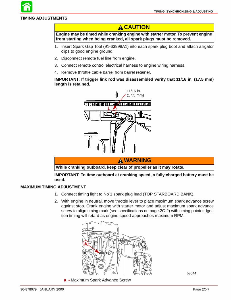
IMPORTANT: If trigger link rod was disassembled verify that 11/16 in. (17.5 mm)length is retained.
11/16 in.(17.5 mm)
WARNINGWhile cranking outboard, keep clear of propeller as it may rotate.
IMPORTANT: To time outboard at cranking speed, a fully charged battery must beused.
MAXIMUM TIMING ADJUSTMENT
1. Connect timing light to No 1 spark plug lead (TOP STARBOARD BANK).
2. With engine in neutral, move throttle lever to place maximum spark advance screwagainst stop. Crank engine with starter motor and adjust maximum spark advancescrew to align timing mark (see specifications on page 2C-2) with timing pointer. Igni-tion timing will retard as engine speed approaches maximum RPM.
58044
a
a - Maximum Spark Advance Screw
MAINTENANCE
Page 2C-8 90-878079 JANUARY 2000
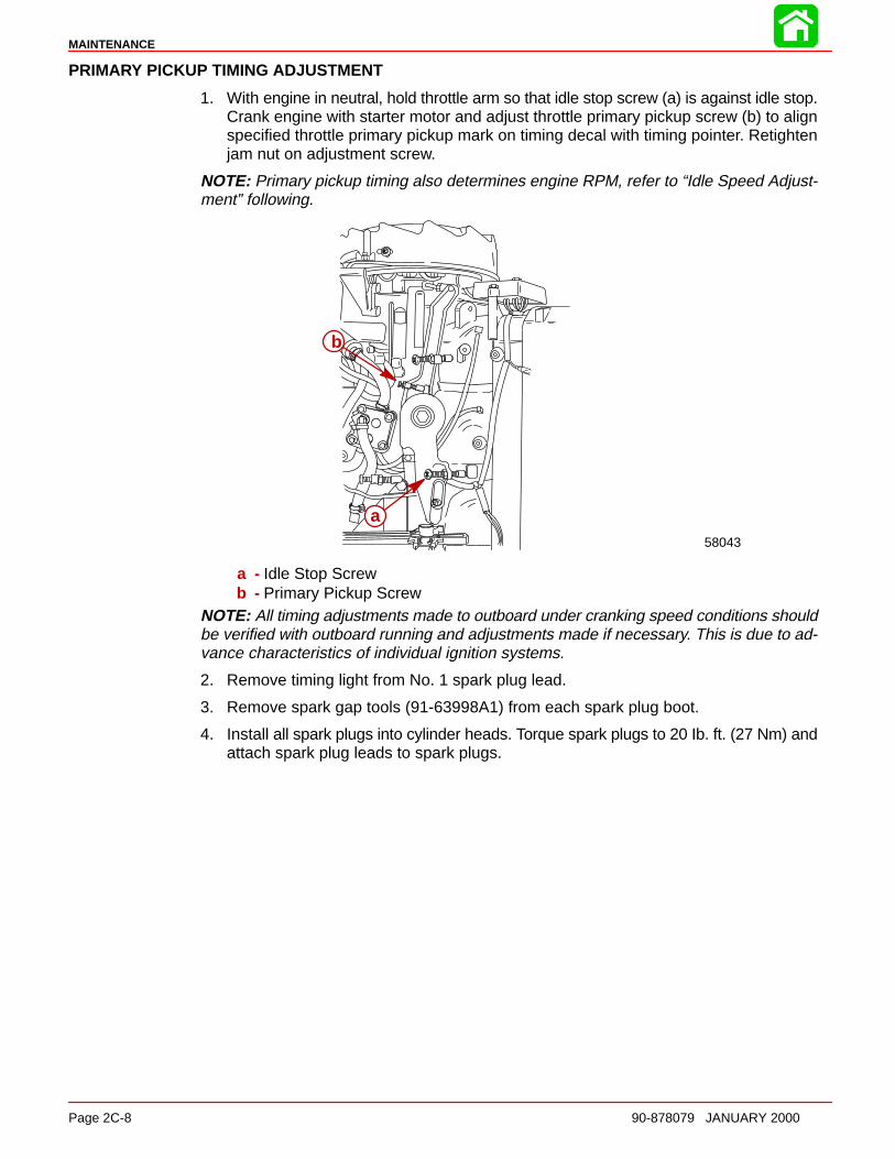
PRIMARY PICKUP TIMING ADJUSTMENT
1. With engine in neutral, hold throttle arm so that idle stop screw (a) is against idle stop.Crank engine with starter motor and adjust throttle primary pickup screw (b) to alignspecified throttle primary pickup mark on timing decal with timing pointer. Retightenjam nut on adjustment screw.
NOTE: Primary pickup timing also determines engine RPM, refer to “Idle Speed Adjust-ment” following.
58043
a
b
a - Idle Stop Screwb - Primary Pickup Screw
NOTE: All timing adjustments made to outboard under cranking speed conditions shouldbe verified with outboard running and adjustments made if necessary. This is due to ad-vance characteristics of individual ignition systems.
2. Remove timing light from No. 1 spark plug lead.
3. Remove spark gap tools (91-63998A1) from each spark plug boot.
4. Install all spark plugs into cylinder heads. Torque spark plugs to 20 Ib. ft. (27 Nm) andattach spark plug leads to spark plugs.
TIMING, SYNCHRONIZING & ADJUSTING
90-878079 JANUARY 2000 Page 2C-9
IDLE SPEED ADJUSTMENT
1. With engine in water, connect fuel line to engine. Start engine and allow to warm up.
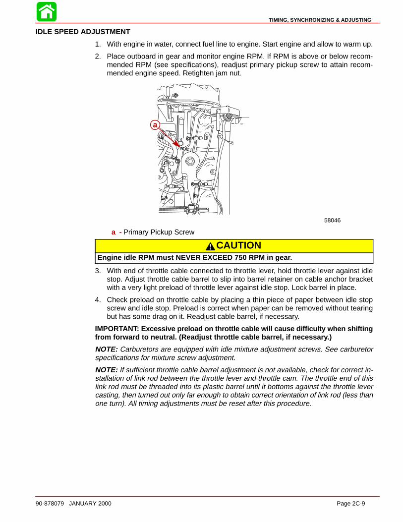
2. Place outboard in gear and monitor engine RPM. If RPM is above or below recom-mended RPM (see specifications), readjust primary pickup screw to attain recom-mended engine speed. Retighten jam nut.
58046
a
a - Primary Pickup Screw
CAUTIONEngine idle RPM must NEVER EXCEED 750 RPM in gea r.
3. With end of throttle cable connected to throttle lever, hold throttle lever against idlestop. Adjust throttle cable barrel to slip into barrel retainer on cable anchor bracketwith a very light preload of throttle lever against idle stop. Lock barrel in place.
4. Check preload on throttle cable by placing a thin piece of paper between idle stopscrew and idle stop. Preload is correct when paper can be removed without tearingbut has some drag on it. Readjust cable barrel, if necessary.
IMPORTANT: Excessive preload on throttle cable will cause difficulty when shiftingfrom forward to neutral. (Readjust throttle cable barrel, if necessar y.)
NOTE: Carburetors are equipped with idle mixture adjustment screws. See carburetorspecifications for mixture screw adjustment.
NOTE: If sufficient throttle cable barrel adjustment is not available, check for correct in-stallation of link rod between the throttle lever and throttle cam. The throttle end of thislink rod must be threaded into its plastic barrel until it bottoms against the throttle levercasting, then turned out only far enough to obtain correct orientation of link rod (less thanone turn). All timing adjustments must be reset after this procedure.
MAINTENANCE
Page 2C-10 90-878079 JANUARY 2000
Adjustments
Electronic Fuel Injection ModelsTIMING POINTER ADJUSTMENT
WARNINGEngine could start when turning flywheel to check timing pointer adjustment. Re-move all spark plugs from engine to prevent engine from starting.
1. Remove all spark plugs and install Dial Indicator (91-58222A1 ) into No. 1 cylinder (topcylinder, starboard bank)
2. Turn flywheel in a clockwise direction until No. 1 piston is at top dead center (TDC).Set dial indicator at “O” (zero) and tighten indicator set screw.
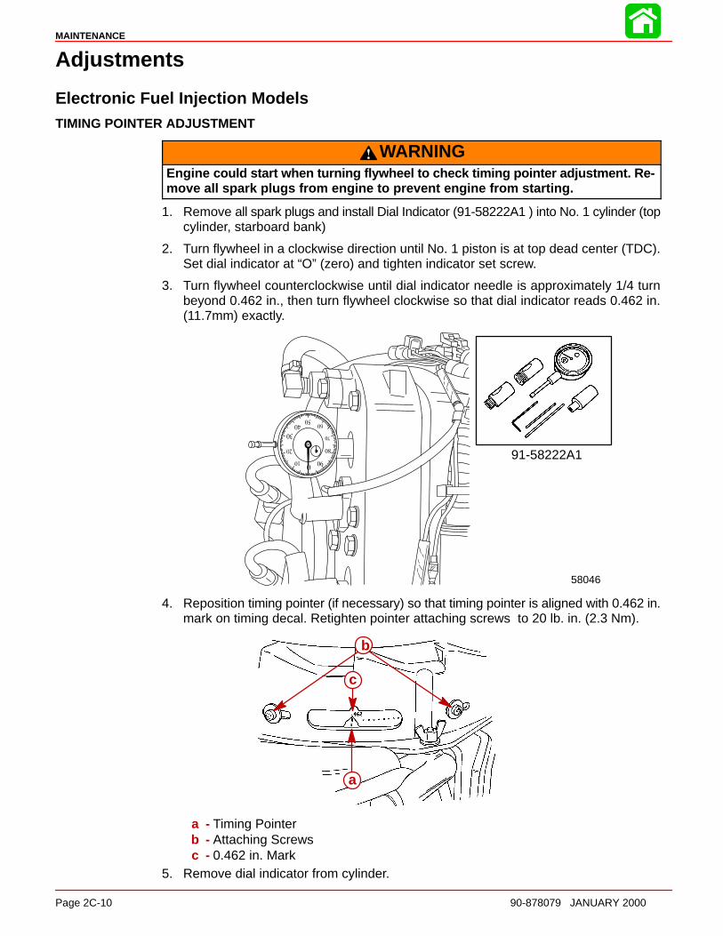
3. Turn flywheel counterclockwise until dial indicator needle is approximately 1/4 turnbeyond 0.462 in., then turn flywheel clockwise so that dial indicator reads 0.462 in.(11.7mm) exactly.
58046
91-58222A1
4. Reposition timing pointer (if necessary) so that timing pointer is aligned with 0.462 in.mark on timing decal. Retighten pointer attaching screws to 20 lb. in. (2.3 Nm).
b
a
c
a - Timing Pointerb - Attaching Screwsc - 0.462 in. Mark
5. Remove dial indicator from cylinder.
TIMING, SYNCHRONIZING & ADJUSTING
90-878079 JANUARY 2000 Page 2C-11
ADJUSTMENTS
CAUTIONEngine is initially timed while cranking engine with starter moto r. To prevent en-gine from starting when being cranked, all spark plugs must be removed, exceptNo.1 cylinder (top cylinder starboard bank) plug.
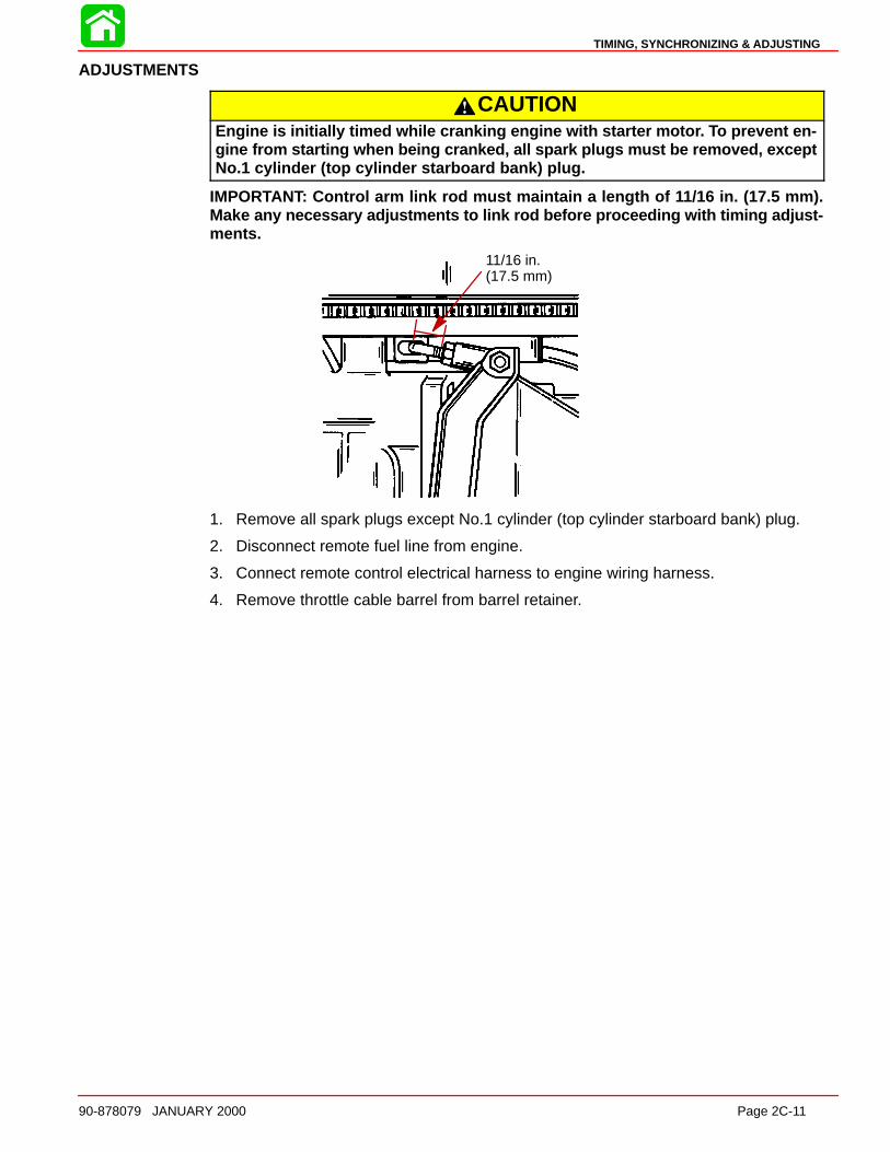
IMPORTANT: Control arm link rod must maintain a length of 11/16 in. (17.5 mm).Make any necessary adjustments to link rod before proceeding with timing adjust-ments.
11/16 in.(17.5 mm)
1. Remove all spark plugs except No.1 cylinder (top cylinder starboard bank) plug.
2. Disconnect remote fuel line from engine.
3. Connect remote control electrical harness to engine wiring harness.
4. Remove throttle cable barrel from barrel retainer.
MAINTENANCE
Page 2C-12 90-878079 JANUARY 2000
THROTTLE CAM ADJUSTMENT
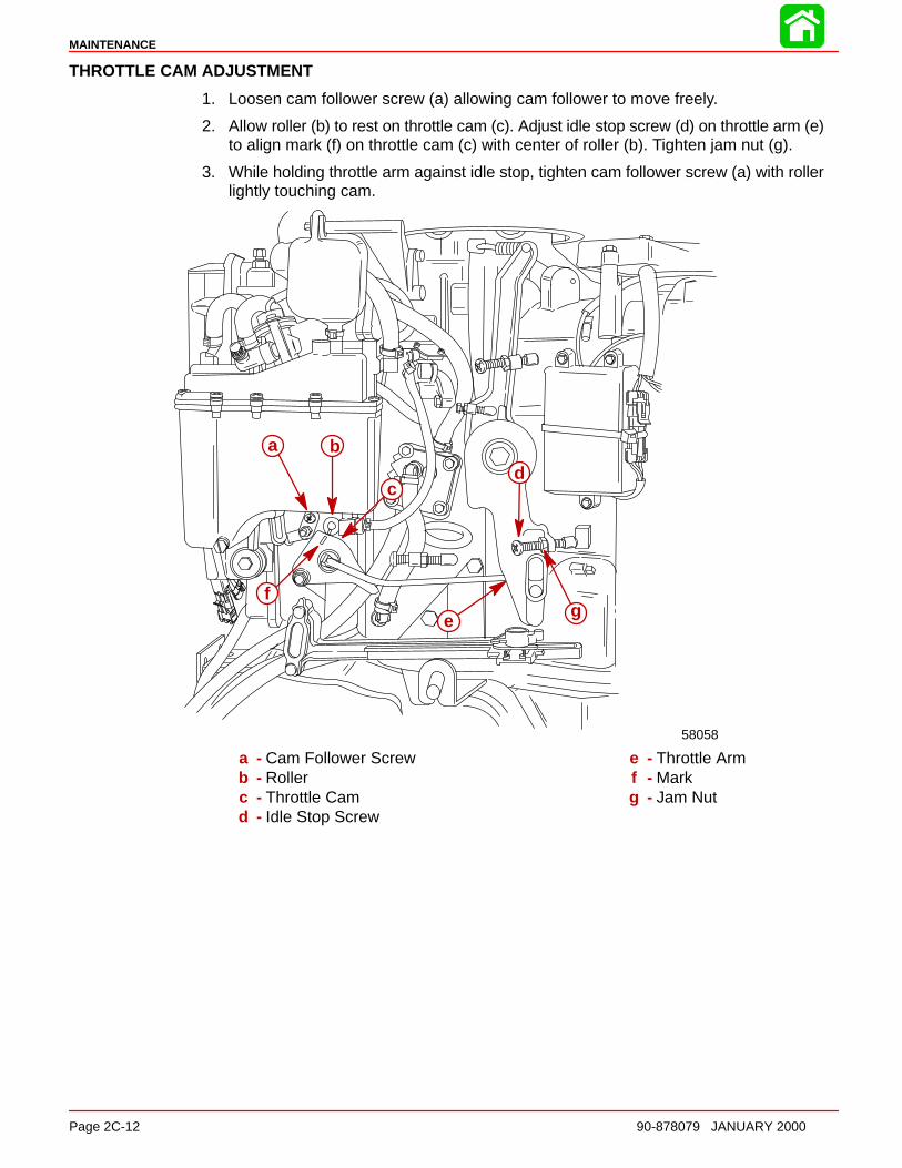
1. Loosen cam follower screw (a) allowing cam follower to move freely.
2. Allow roller (b) to rest on throttle cam (c). Adjust idle stop screw (d) on throttle arm (e)to align mark (f) on throttle cam (c) with center of roller (b). Tighten jam nut (g).
3. While holding throttle arm against idle stop, tighten cam follower screw (a) with rollerlightly touching cam.
58058
a b
cd
e
fg
a - Cam Follower Screwb - Rollerc - Throttle Camd - Idle Stop Screw
e - Throttle Armf - Markg - Jam Nut
TIMING, SYNCHRONIZING & ADJUSTING
90-878079 JANUARY 2000 Page 2C-13
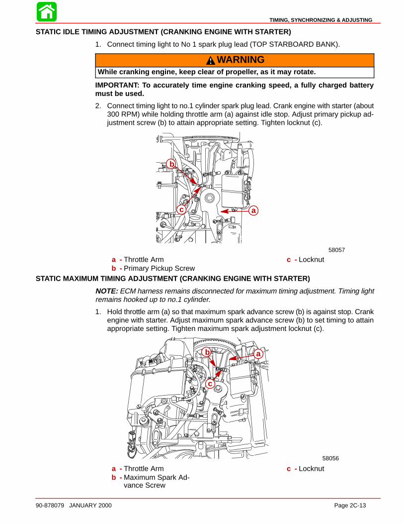
STATIC IDLE TIMING ADJUSTMENT (CRANKING ENGINE WITH S TARTER)
1. Connect timing light to No 1 spark plug lead (TOP STARBOARD BANK).
WARNINGWhile cranking engine, keep clear of propelle r, as it may rotate.
IMPORTANT: To accurately time engine cranking speed, a fully charged batterymust be used.
2. Connect timing light to no.1 cylinder spark plug lead. Crank engine with starter (about300 RPM) while holding throttle arm (a) against idle stop. Adjust primary pickup ad-justment screw (b) to attain appropriate setting. Tighten locknut (c).
58057
ac
b
a - Throttle Armb - Primary Pickup Screw
c - Locknut
STATIC MAXIMUM TIMING ADJUSTMENT (CRANKING ENGINE WITH S TARTER)
NOTE: ECM harness remains disconnected for maximum timing adjustment. Timing lightremains hooked up to no.1 cylinder.
1. Hold throttle arm (a) so that maximum spark advance screw (b) is against stop. Crankengine with starter. Adjust maximum spark advance screw (b) to set timing to attainappropriate setting. Tighten maximum spark adjustment locknut (c).
58056
b
c
a
a - Throttle Armb - Maximum Spark Ad-
vance Screw
c - Locknut
MAINTENANCE
Page 2C-14 90-878079 JANUARY 2000
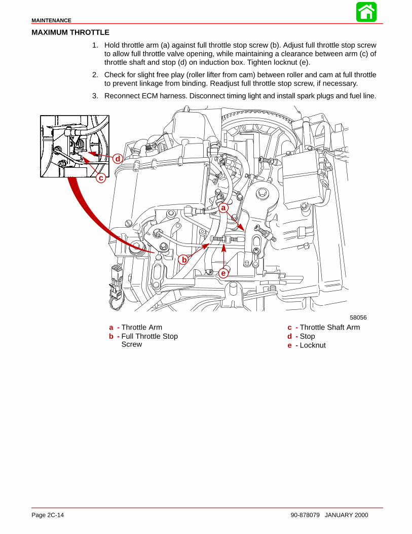
MAXIMUM THROTTLE
1. Hold throttle arm (a) against full throttle stop screw (b). Adjust full throttle stop screwto allow full throttle valve opening, while maintaining a clearance between arm (c) ofthrottle shaft and stop (d) on induction box. Tighten locknut (e).
2. Check for slight free play (roller lifter from cam) between roller and cam at full throttleto prevent linkage from binding. Readjust full throttle stop screw, if necessary.
3. Reconnect ECM harness. Disconnect timing light and install spark plugs and fuel line.
a
b
c
d
e
58056
a - Throttle Armb - Full Throttle Stop
Screw
c - Throttle Shaft Armd - Stope - Locknut
TIMING, SYNCHRONIZING & ADJUSTING
90-878079 JANUARY 2000 Page 2C-15
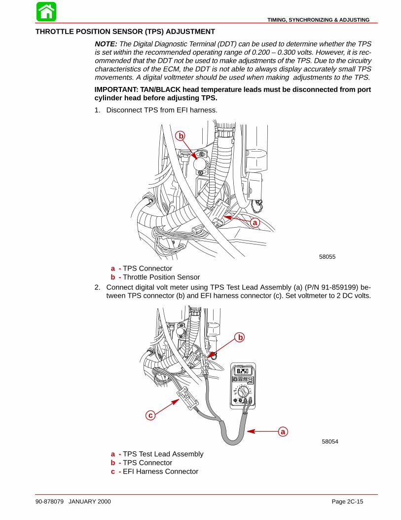
THROTTLE POSITION SENSOR (TPS) ADJUSTMENT
NOTE: The Digital Diagnostic Terminal (DDT) can be used to determine whether the TPSis set within the recommended operating range of 0.200 – 0.300 volts. However, it is rec-ommended that the DDT not be used to make adjustments of the TPS. Due to the circuitrycharacteristics of the ECM, the DDT is not able to always display accurately small TPSmovements. A digital voltmeter should be used when making adjustments to the TPS.
IMPORTANT: TAN/BLACK head temperature leads must be disconnected from portcylinder head before adjusting TPS.
1. Disconnect TPS from EFI harness.
58055
a
b
a - TPS Connectorb - Throttle Position Sensor
2. Connect digital volt meter using TPS Test Lead Assembly (a) (P/N 91-859199) be-tween TPS connector (b) and EFI harness connector (c). Set voltmeter to 2 DC volts.
58054
a
b
c
a - TPS Test Lead Assemblyb - TPS Connectorc - EFI Harness Connector
MAINTENANCE
Page 2C-16 90-878079 JANUARY 2000
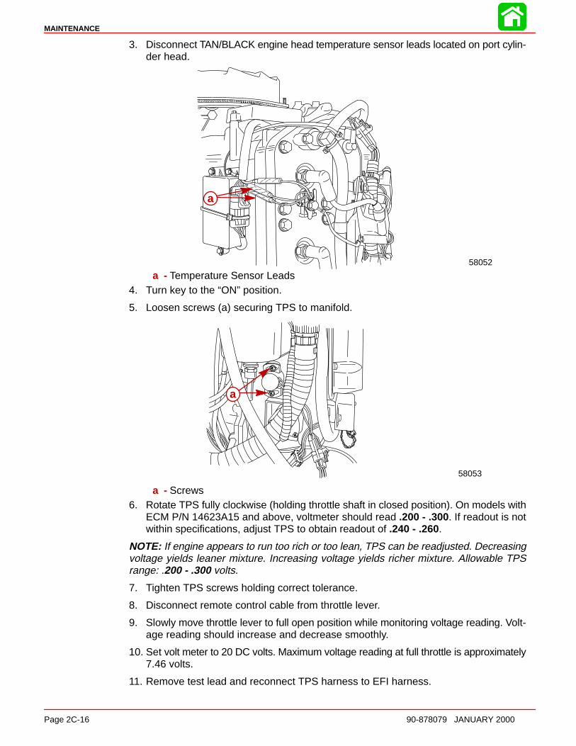
3. Disconnect TAN/BLACK engine head temperature sensor leads located on port cylin-der head.
58052
a
a - Temperature Sensor Leads4. Turn key to the “ON” position.
5. Loosen screws (a) securing TPS to manifold.
58053
a
a - Screws6. Rotate TPS fully clockwise (holding throttle shaft in closed position). On models with
ECM P/N 14623A15 and above, voltmeter should read .200 - .300. If readout is notwithin specifications, adjust TPS to obtain readout of .240 - .260.
NOTE: If engine appears to run too rich or too lean, TPS can be readjusted. Decreasingvoltage yields leaner mixture. Increasing voltage yields richer mixture. Allowable TPSrange: .200 - .300 volts.
7. Tighten TPS screws holding correct tolerance.
8. Disconnect remote control cable from throttle lever.
9. Slowly move throttle lever to full open position while monitoring voltage reading. Volt-age reading should increase and decrease smoothly.
10. Set volt meter to 20 DC volts. Maximum voltage reading at full throttle is approximately7.46 volts.
11. Remove test lead and reconnect TPS harness to EFI harness.
TIMING, SYNCHRONIZING & ADJUSTING
90-878079 JANUARY 2000 Page 2C-17
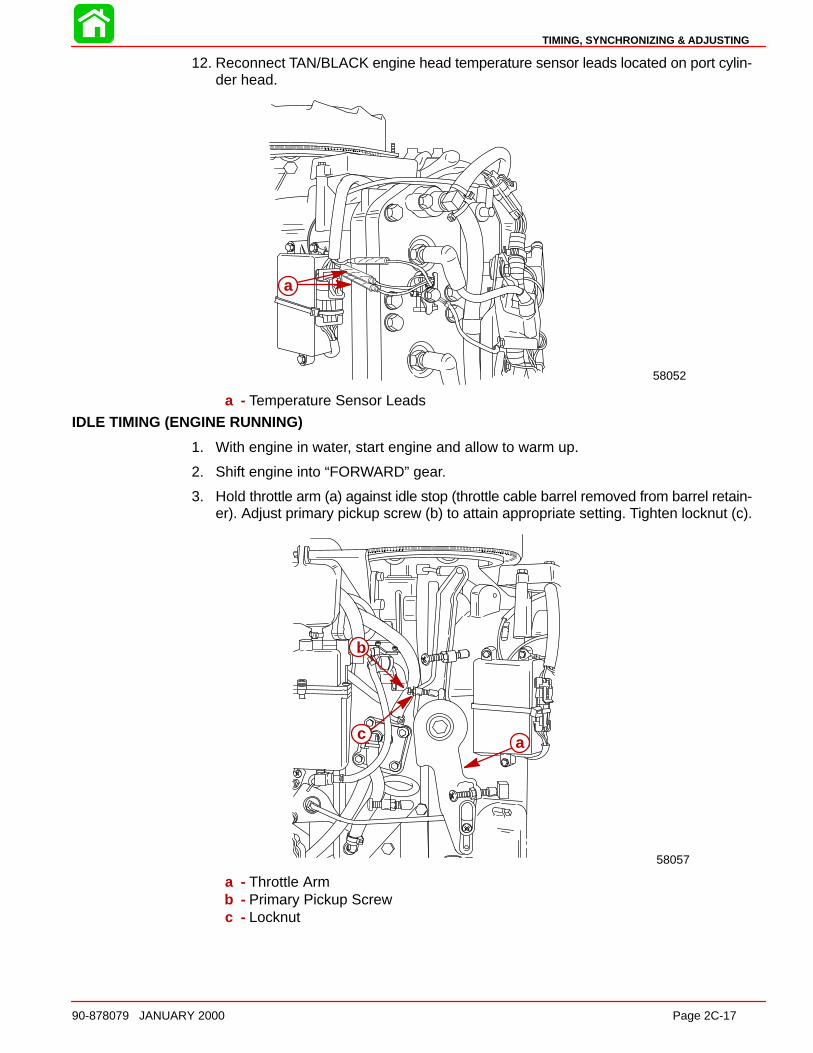
12. Reconnect TAN/BLACK engine head temperature sensor leads located on port cylin-der head.
58052
a
a - Temperature Sensor Leads
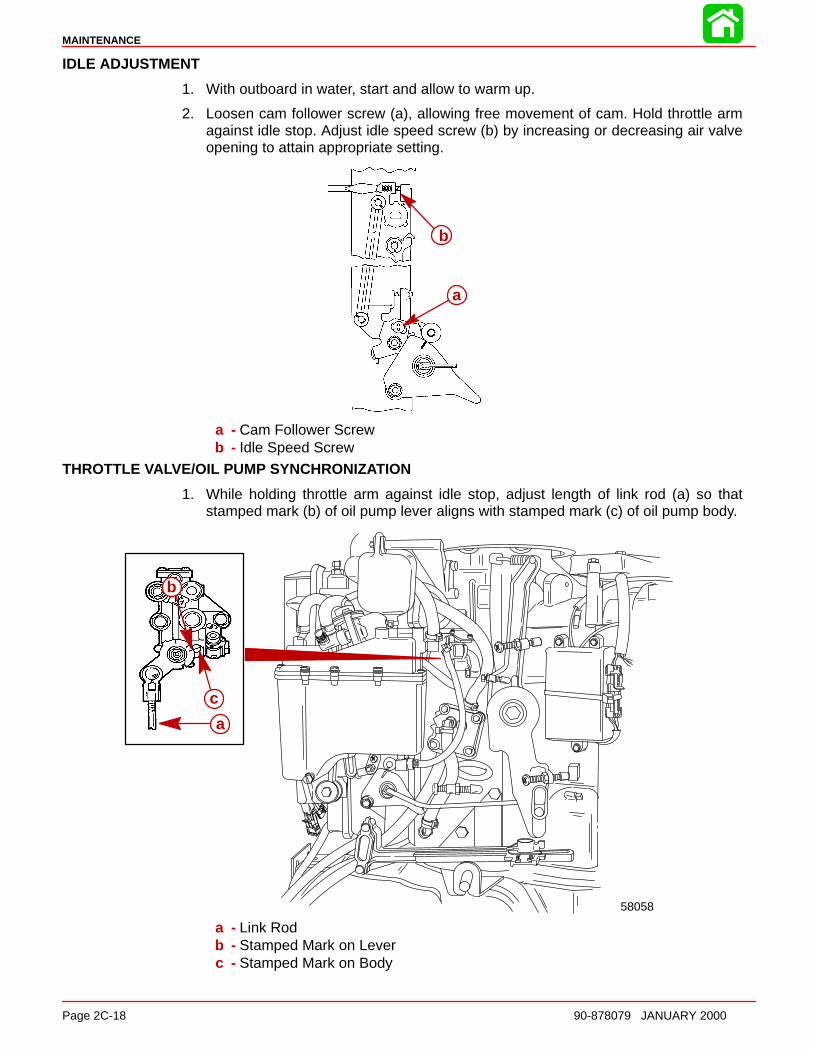
IDLE TIMING (ENGINE RUNNING)
1. With engine in water, start engine and allow to warm up.
2. Shift engine into “FORWARD” gear.
3. Hold throttle arm (a) against idle stop (throttle cable barrel removed from barrel retain-er). Adjust primary pickup screw (b) to attain appropriate setting. Tighten locknut (c).
58057
b
c a
a - Throttle Armb - Primary Pickup Screwc - Locknut
MAINTENANCE
Page 2C-18 90-878079 JANUARY 2000
IDLE ADJUSTMENT
1. With outboard in water, start and allow to warm up.
2. Loosen cam follower screw (a), allowing free movement of cam. Hold throttle armagainst idle stop. Adjust idle speed screw (b) by increasing or decreasing air valveopening to attain appropriate setting.
a
b
a - Cam Follower Screwb - Idle Speed Screw
THROTTLE VALVE/OIL PUMP SYNCHRONIZATION
1. While holding throttle arm against idle stop, adjust length of link rod (a) so thatstamped mark (b) of oil pump lever aligns with stamped mark (c) of oil pump body.
58058
a
c
b
a - Link Rodb - Stamped Mark on Leverc - Stamped Mark on Body
TIMING, SYNCHRONIZING & ADJUSTING
90-878079 JANUARY 2000 Page 2C-19
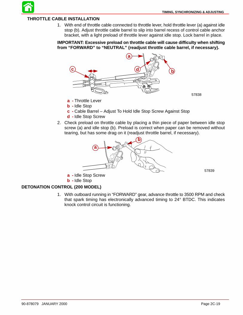
THROTTLE CABLE INS TALL ATION1. With end of throttle cable connected to throttle lever, hold throttle lever (a) against idle
stop (b). Adjust throttle cable barrel to slip into barrel recess of control cable anchorbracket, with a light preload of throttle lever against idle stop. Lock barrel in place.
IMPORTANT: Excessive preload on throttle cable will cause difficulty when shiftingfrom “FO RWARD” to “NEUTRAL” (readjust throttle cable barrel, if necessary).
57838
b
a
c d
a - Throttle Leverb - Idle Stopc - Cable Barrel – Adjust To Hold Idle Stop Screw Against Stopd - Idle Stop Screw
2. Check preload on throttle cable by placing a thin piece of paper between idle stopscrew (a) and idle stop (b). Preload is correct when paper can be removed withouttearing, but has some drag on it (readjust throttle barrel, if necessary).
a
b
57839a - Idle Stop Screwb - Idle Stop
DETONATION CONTROL (200 MODEL)
1. With outboard running in “FORWARD” gear, advance throttle to 3500 RPM and checkthat spark timing has electronically advanced timing to 24° BTDC. This indicatesknock control circuit is functioning.
MAINTENANCE
Page 2C-20 90-878079 JANUARY 2000
MAXIMUM TIMING ADJUSTMENT (ENGINE RUNNING)
1. Disconnect WHITE/BLUE lead (a) from detonation sensor (b). (200 model)
58041
a
b
a - WHITE/BLUE Leadb - Detonation Sensor
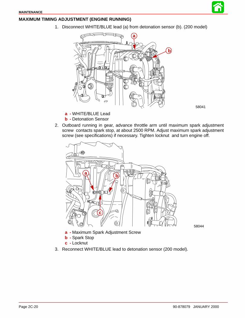
2. Outboard running in gear, advance throttle arm until maximum spark adjustmentscrew contacts spark stop, at about 2500 RPM. Adjust maximum spark adjustmentscrew (see specifications) if necessary. Tighten locknut and turn engine off.
58044
a b
c
a - Maximum Spark Adjustment Screwb - Spark Stopc - Locknut
3. Reconnect WHITE/BLUE lead to detonation sensor (200 model).


![Adjusting the Accounts - BrainMass1].pdf · Adjusting the Accounts Timing Issues • Time period assumption • Fiscal and calendar years •Accrual- vs. cash-basis accounting •Recognizing](https://img.dokumen.tips/doc/110x75/5e78957ef90772049d646d10/adjusting-the-accounts-brainmass-1pdf-adjusting-the-accounts-timing-issues.jpg)