Embed Size (px)
Citation preview
SG24-5470-00
International Technical Support Organization
www.redbooks.ibm.com
Introduction to Storage Area Network, SAN
Ravi Kumar Khattar, Mark S. Murphy, Giulio John Tarella,Kjell E. Nystrom


Introduction to Storage Area Network, SAN
August 1999
SG24-5470-00
International Technical Support Organization
© Copyright International Business Machines Corporation 1999. All rights reserved.Note to U.S Government Users – Documentation related to restricted rights – Use, duplication or disclosure issubject to restrictions set forth in GSA ADP Schedule Contract with IBM Corp.
First Edition (August 1999)
This edition is based on information available in July, 1999.
Comments may be addressed to:IBM Corporation, International Technical Support OrganizationDept. QXXE Building 80-E2650 Harry RoadSan Jose, California 95120-6099
When you send information to IBM, you grant IBM a non-exclusive right to use or distribute theinformation in any way it believes appropriate without incurring any obligation to you.
Before using this information and the product it supports, be sure to read the general information inAppendix B, “Special Notices” on page 111.
Take Note!

Contents
Figures . . . . . . . . . . . . . . . . . . . . . . . . . . . . . . . . . . . . . . . . . . . . . . . . . . . vii
Preface . . . . . . . . . . . . . . . . . . . . . . . . . . . . . . . . . . . . . . . . . . . . . . . . . . . .ixThe Team That Wrote This Redbook . . . . . . . . . . . . . . . . . . . . . . . . . . . . . . . . . ixComments Welcome . . . . . . . . . . . . . . . . . . . . . . . . . . . . . . . . . . . . . . . . . . . . xiii
Chapter 1. The Market Perception of Storage Area Networks . . . . . . . . 11.1 Evolution of Storage Devices Connectivity . . . . . . . . . . . . . . . . . . . . . . 41.2 Evolution to SAN . . . . . . . . . . . . . . . . . . . . . . . . . . . . . . . . . . . . . . . . . 7
1.2.1 Fibre Channel Architecture . . . . . . . . . . . . . . . . . . . . . . . . . . . . . . 81.3 SAN Components. . . . . . . . . . . . . . . . . . . . . . . . . . . . . . . . . . . . . . . . 10
1.3.1 SAN Servers. . . . . . . . . . . . . . . . . . . . . . . . . . . . . . . . . . . . . . . . 111.3.2 SAN Storage . . . . . . . . . . . . . . . . . . . . . . . . . . . . . . . . . . . . . . . 111.3.3 SAN Interconnects . . . . . . . . . . . . . . . . . . . . . . . . . . . . . . . . . . . 121.3.4 SAN Applications . . . . . . . . . . . . . . . . . . . . . . . . . . . . . . . . . . . . 161.3.5 Managing the SAN . . . . . . . . . . . . . . . . . . . . . . . . . . . . . . . . . . . 20
1.4 Where We Are Today . . . . . . . . . . . . . . . . . . . . . . . . . . . . . . . . . . . . . 221.4.1 Server Attached Storage . . . . . . . . . . . . . . . . . . . . . . . . . . . . . . 221.4.2 Network Attached Storage . . . . . . . . . . . . . . . . . . . . . . . . . . . . . 231.4.3 Data-Centric . . . . . . . . . . . . . . . . . . . . . . . . . . . . . . . . . . . . . . . . 24
Chapter 2. The IBM SAN Initiative . . . . . . . . . . . . . . . . . . . . . . . . . . . . . 272.1 New Paradigms: e-Business. . . . . . . . . . . . . . . . . . . . . . . . . . . . . . . . 27
2.1.1 Storage Technology Trends . . . . . . . . . . . . . . . . . . . . . . . . . . . . 272.1.2 Trends Driving SANs . . . . . . . . . . . . . . . . . . . . . . . . . . . . . . . . . 282.1.3 SAN Status Today . . . . . . . . . . . . . . . . . . . . . . . . . . . . . . . . . . . 302.1.4 SAN Evolution . . . . . . . . . . . . . . . . . . . . . . . . . . . . . . . . . . . . . . 30
2.2 The IBM Response. . . . . . . . . . . . . . . . . . . . . . . . . . . . . . . . . . . . . . . 312.2.1 The Promise of Value . . . . . . . . . . . . . . . . . . . . . . . . . . . . . . . . . 322.2.2 IBM Global Services . . . . . . . . . . . . . . . . . . . . . . . . . . . . . . . . . . 352.2.3 IBM and Industry Standards Organizations. . . . . . . . . . . . . . . . . 35
Chapter 3. SAN Servers and Storage . . . . . . . . . . . . . . . . . . . . . . . . . . 373.1 Servers and Storage Environments . . . . . . . . . . . . . . . . . . . . . . . . . . 38
3.1.1 The Challenge . . . . . . . . . . . . . . . . . . . . . . . . . . . . . . . . . . . . . . 403.2 Server Environments . . . . . . . . . . . . . . . . . . . . . . . . . . . . . . . . . . . . . 42
3.2.1 S/390 Servers. . . . . . . . . . . . . . . . . . . . . . . . . . . . . . . . . . . . . . . 423.2.2 RS/6000 Servers and UNIX Servers . . . . . . . . . . . . . . . . . . . . . . 433.2.3 AS/400 Servers . . . . . . . . . . . . . . . . . . . . . . . . . . . . . . . . . . . . . 443.2.4 Windows NT and Netfinity Servers . . . . . . . . . . . . . . . . . . . . . . . 46
3.3 Disclaimer Statement . . . . . . . . . . . . . . . . . . . . . . . . . . . . . . . . . . . . . 47
© Copyright IBM Corp. 1999 iii

Chapter 4. SAN Fabrics and Connectivity . . . . . . . . . . . . . . . . . . . . . . 494.1 Fabric . . . . . . . . . . . . . . . . . . . . . . . . . . . . . . . . . . . . . . . . . . . . . . . . . 494.2 Storage Area Network Environment . . . . . . . . . . . . . . . . . . . . . . . . . . 49
4.2.1 Server-Attached Storage (SAS) . . . . . . . . . . . . . . . . . . . . . . . . . 504.2.2 Network-Attached Storage (NAS) . . . . . . . . . . . . . . . . . . . . . . . . 514.2.3 Storage Area Network (SAN) . . . . . . . . . . . . . . . . . . . . . . . . . . . 52
4.3 Fibre Channel. . . . . . . . . . . . . . . . . . . . . . . . . . . . . . . . . . . . . . . . . . . 524.3.1 Point-to-Point . . . . . . . . . . . . . . . . . . . . . . . . . . . . . . . . . . . . . . 534.3.2 Loops and Hubs for Connectivity . . . . . . . . . . . . . . . . . . . . . . . . 534.3.3 Switches for Scalability, Performance and Availability . . . . . . . . 554.3.4 Switched Fabric without Cascading . . . . . . . . . . . . . . . . . . . . . . 554.3.5 Switched Fabric with Cascading . . . . . . . . . . . . . . . . . . . . . . . . . 564.3.6 Hubs versus Switches . . . . . . . . . . . . . . . . . . . . . . . . . . . . . . . . 574.3.7 Mixed Switch and Loop Topologies . . . . . . . . . . . . . . . . . . . . . . 584.3.8 ESCON Directors . . . . . . . . . . . . . . . . . . . . . . . . . . . . . . . . . . . . 594.3.9 FICON Directors . . . . . . . . . . . . . . . . . . . . . . . . . . . . . . . . . . . . . 594.3.10 Routers and Bridges . . . . . . . . . . . . . . . . . . . . . . . . . . . . . . . . . 604.3.11 Gateways . . . . . . . . . . . . . . . . . . . . . . . . . . . . . . . . . . . . . . . . . 61
Chapter 5. SAN Management . . . . . . . . . . . . . . . . . . . . . . . . . . . . . . . . . 635.1 Is SAN Management Required? . . . . . . . . . . . . . . . . . . . . . . . . . . . . . 635.2 SAN Management Evolving Standards and Definitions . . . . . . . . . . . . 64
5.2.1 SAN Storage Level . . . . . . . . . . . . . . . . . . . . . . . . . . . . . . . . . . . 655.2.2 SAN Network Level . . . . . . . . . . . . . . . . . . . . . . . . . . . . . . . . . . 655.2.3 Enterprise Systems Level . . . . . . . . . . . . . . . . . . . . . . . . . . . . . . 67
5.3 SAN Management Strategy and Disciplines . . . . . . . . . . . . . . . . . . . . 685.3.1 SAN Management Strategy . . . . . . . . . . . . . . . . . . . . . . . . . . . . 68
5.4 General Issues in Fibre Channel Arbitrated Loop Management . . . . . 695.4.1 In-Band and Out-of-Band Management . . . . . . . . . . . . . . . . . . . 70
5.5 Troubleshooting . . . . . . . . . . . . . . . . . . . . . . . . . . . . . . . . . . . . . . . . . 715.5.1 Arbitrated Loops . . . . . . . . . . . . . . . . . . . . . . . . . . . . . . . . . . . . . 715.5.2 Switched Environments . . . . . . . . . . . . . . . . . . . . . . . . . . . . . . . 71
5.6 IBM StorWatch . . . . . . . . . . . . . . . . . . . . . . . . . . . . . . . . . . . . . . . . . . 715.6.1 StorWatch Serial Storage Expert . . . . . . . . . . . . . . . . . . . . . . . . 725.6.2 StorWatch Versatile Storage Specialist. . . . . . . . . . . . . . . . . . . . 725.6.3 StorWatch Enterprise Storage Server Specialist . . . . . . . . . . . . . 735.6.4 StorWatch Enterprise Storage Server Expert . . . . . . . . . . . . . . . 735.6.5 StorWatch DFSMShsm Monitor . . . . . . . . . . . . . . . . . . . . . . . . . 735.6.6 StorWatch Reporter . . . . . . . . . . . . . . . . . . . . . . . . . . . . . . . . . . 735.6.7 StorWatch Fiber Channel RAID Specialist . . . . . . . . . . . . . . . . . 735.6.8 StorWatch SAN Data Gateway Specialist . . . . . . . . . . . . . . . . . . 735.6.9 StorWatch SAN Data Gateway S20 Specialist . . . . . . . . . . . . . . 745.6.10 StorWatch SAN Fibre Channel Switch Specialist . . . . . . . . . . . 74
iv Introduction to Storage Area Network, SAN

5.6.11 StorWatch Data Path Optimizer . . . . . . . . . . . . . . . . . . . . . . . . 74
Chapter 6. SAN Exploitation and Solutions . . . . . . . . . . . . . . . . . . . . . 756.1 The SAN Toolbox . . . . . . . . . . . . . . . . . . . . . . . . . . . . . . . . . . . . . . . . 756.2 Connectivity . . . . . . . . . . . . . . . . . . . . . . . . . . . . . . . . . . . . . . . . . . . . 776.3 Resource Pooling Solutions . . . . . . . . . . . . . . . . . . . . . . . . . . . . . . . . 78
6.3.1 Adding Capacity . . . . . . . . . . . . . . . . . . . . . . . . . . . . . . . . . . . . . 786.3.2 Disk Pooling . . . . . . . . . . . . . . . . . . . . . . . . . . . . . . . . . . . . . . . . 786.3.3 Tape Pooling . . . . . . . . . . . . . . . . . . . . . . . . . . . . . . . . . . . . . . . 806.3.4 Server Clustering . . . . . . . . . . . . . . . . . . . . . . . . . . . . . . . . . . . . 81
6.4 Pooling Solutions, Storage and Data Sharing . . . . . . . . . . . . . . . . . . . 836.4.1 From Storage Partitioning to Data Sharing . . . . . . . . . . . . . . . . . 846.4.2 Data Copy-Sharing . . . . . . . . . . . . . . . . . . . . . . . . . . . . . . . . . . . 866.4.3 True Data Sharing . . . . . . . . . . . . . . . . . . . . . . . . . . . . . . . . . . . 86
6.5 Data Movement Solutions . . . . . . . . . . . . . . . . . . . . . . . . . . . . . . . . . 896.5.1 Media Migration . . . . . . . . . . . . . . . . . . . . . . . . . . . . . . . . . . . . . 896.5.2 Data Migration and Recall . . . . . . . . . . . . . . . . . . . . . . . . . . . . . 896.5.3 Data Copy Services . . . . . . . . . . . . . . . . . . . . . . . . . . . . . . . . . . 90
6.6 Backup and Recovery Solutions . . . . . . . . . . . . . . . . . . . . . . . . . . . . . 916.6.1 LAN-Less Data Movement . . . . . . . . . . . . . . . . . . . . . . . . . . . . . 916.6.2 Server-Free Data Movement . . . . . . . . . . . . . . . . . . . . . . . . . . . 936.6.3 Disaster Backup and Recovery. . . . . . . . . . . . . . . . . . . . . . . . . . 94
Chapter 7. SAN Standardization Organizations . . . . . . . . . . . . . . . . . . 977.1 SAN Industry Associations and Organizations . . . . . . . . . . . . . . . . . . 98
7.1.1 Storage Networking Industry Association — SNIA . . . . . . . . . . . 987.1.2 Fibre Channel Association — FCA . . . . . . . . . . . . . . . . . . . . . . . 997.1.3 Fibre Channel Community — FClC . . . . . . . . . . . . . . . . . . . . . . . 997.1.4 The SCSI Trade Association — STA . . . . . . . . . . . . . . . . . . . . . 997.1.5 Future I/O . . . . . . . . . . . . . . . . . . . . . . . . . . . . . . . . . . . . . . . . . 1007.1.6 StoreX . . . . . . . . . . . . . . . . . . . . . . . . . . . . . . . . . . . . . . . . . . . 1007.1.7 Internet Engineering Task Force - IETF . . . . . . . . . . . . . . . . . . 1007.1.8 American National Standards Organization - ANSI . . . . . . . . . . 100
Appendix A. Comparison of OS/390 and Open System Storage . . . . 1017.2 Managing Files . . . . . . . . . . . . . . . . . . . . . . . . . . . . . . . . . . . . . . . . . 1027.3 Managing Volumes. . . . . . . . . . . . . . . . . . . . . . . . . . . . . . . . . . . . . . 1047.4 Storage Device Attachment . . . . . . . . . . . . . . . . . . . . . . . . . . . . . . . 1077.5 Volume Sharing . . . . . . . . . . . . . . . . . . . . . . . . . . . . . . . . . . . . . . . . 1097.6 Caching . . . . . . . . . . . . . . . . . . . . . . . . . . . . . . . . . . . . . . . . . . . . . . 110
v
Appendix B. Special Notices . . . . . . . . . . . . . . . . . . . . . . . . . . . . . . . . . . 111
Appendix C. Related Publications. . . . . . . . . . . . . . . . . . . . . . . . . . . . . . 115C.1 International Technical Support Organization Publications . . . . . . . . . . 115C.2 Redbooks on CD-ROMs . . . . . . . . . . . . . . . . . . . . . . . . . . . . . . . . . . . . . 116
How to Get ITSO Redbooks . . . . . . . . . . . . . . . . . . . . . . . . . . . . . . . . . 117IBM Redbook Fax Order Form . . . . . . . . . . . . . . . . . . . . . . . . . . . . . . . . . . . . 118
Glossary . . . . . . . . . . . . . . . . . . . . . . . . . . . . . . . . . . . . . . . . . . . . . . . . 119
List of Abbreviations. . . . . . . . . . . . . . . . . . . . . . . . . . . . . . . . . . . . . . . 129
Index . . . . . . . . . . . . . . . . . . . . . . . . . . . . . . . . . . . . . . . . . . . . . . . . . . . 131
ITSO Redbook Evaluation . . . . . . . . . . . . . . . . . . . . . . . . . . . . . . . . . . . 137
vi Introduction to Storage Area Network, SAN
Figures
1. Islands of Information. . . . . . . . . . . . . . . . . . . . . . . . . . . . . . . . . . . . . . . . . . 22. What is a SAN? . . . . . . . . . . . . . . . . . . . . . . . . . . . . . . . . . . . . . . . . . . . . . . 33. SAN Components . . . . . . . . . . . . . . . . . . . . . . . . . . . . . . . . . . . . . . . . . . . 114. SAN Applications . . . . . . . . . . . . . . . . . . . . . . . . . . . . . . . . . . . . . . . . . . . . 175. Data Sharing Concepts and Types . . . . . . . . . . . . . . . . . . . . . . . . . . . . . . 186. IBM’s ESRM Disciplines . . . . . . . . . . . . . . . . . . . . . . . . . . . . . . . . . . . . . . 217. Server-Centric . . . . . . . . . . . . . . . . . . . . . . . . . . . . . . . . . . . . . . . . . . . . . . 238. File-Centric. . . . . . . . . . . . . . . . . . . . . . . . . . . . . . . . . . . . . . . . . . . . . . . . . 249. Data-Centric. . . . . . . . . . . . . . . . . . . . . . . . . . . . . . . . . . . . . . . . . . . . . . . . 2510. Storage with a SAN . . . . . . . . . . . . . . . . . . . . . . . . . . . . . . . . . . . . . . . . . . 3111. IBM Organizational Approach to SANs . . . . . . . . . . . . . . . . . . . . . . . . . . . 3212. Outline of IBM SAN Promise of Value . . . . . . . . . . . . . . . . . . . . . . . . . . . . 3313. Outline of IBM SAN Initiative . . . . . . . . . . . . . . . . . . . . . . . . . . . . . . . . . . . 3714. Evolutions in Storage Architecture. . . . . . . . . . . . . . . . . . . . . . . . . . . . . . . 3815. Islands of Distributed Information . . . . . . . . . . . . . . . . . . . . . . . . . . . . . . . 3916. Disk and Tape Storage and Data Consolidation . . . . . . . . . . . . . . . . . . . . 4017. IBM Storage Strategy. . . . . . . . . . . . . . . . . . . . . . . . . . . . . . . . . . . . . . . . . 4118. Hardware and Operating Systems Differences . . . . . . . . . . . . . . . . . . . . . 4219. S/390 Processor to Storage Interface Connections. . . . . . . . . . . . . . . . . . 4320. RS6000 Processor to Storage Interconnections . . . . . . . . . . . . . . . . . . . . 4421. AS400 Hardware Design . . . . . . . . . . . . . . . . . . . . . . . . . . . . . . . . . . . . . . 4522. OS/400 versus NT or UNIX Storage Addressing . . . . . . . . . . . . . . . . . . . . 4623. Netfinity Processor to Storage Interconnections . . . . . . . . . . . . . . . . . . . . 4724. Outline of IBM SAN Initiative . . . . . . . . . . . . . . . . . . . . . . . . . . . . . . . . . . . 4925. Server-Attached Storage (SAS). . . . . . . . . . . . . . . . . . . . . . . . . . . . . . . . . 5026. Network Attached Storage (NAS) . . . . . . . . . . . . . . . . . . . . . . . . . . . . . . . 5127. Storage Area Network (SAN). . . . . . . . . . . . . . . . . . . . . . . . . . . . . . . . . . . 5228. Fibre Channel Point-to-Point Topology . . . . . . . . . . . . . . . . . . . . . . . . . . . 5329. Fibre Channel Loop Topology . . . . . . . . . . . . . . . . . . . . . . . . . . . . . . . . . . 5430. Fibre Channel Switched Topology . . . . . . . . . . . . . . . . . . . . . . . . . . . . . . . 5531. Fibre Channel Switched Topology (Non-Cascaded Switches) . . . . . . . . . 5632. Fibre Channel Switched Topology (Cascaded Switches) . . . . . . . . . . . . . 5733. Switch Attached Arbitrated Loop . . . . . . . . . . . . . . . . . . . . . . . . . . . . . . . . 5834. ESCON Storage Area Network . . . . . . . . . . . . . . . . . . . . . . . . . . . . . . . . . 5935. FICON Switched Storage Area Network . . . . . . . . . . . . . . . . . . . . . . . . . . 6036. IBM SAN Data Gateway . . . . . . . . . . . . . . . . . . . . . . . . . . . . . . . . . . . . . . 6137. SAN Gateway Connecting Remote SANs . . . . . . . . . . . . . . . . . . . . . . . . . 6138. IBM SAN Initiative . . . . . . . . . . . . . . . . . . . . . . . . . . . . . . . . . . . . . . . . . . . 6339. SAN Management Levels . . . . . . . . . . . . . . . . . . . . . . . . . . . . . . . . . . . . . 6440. Elements of SNMP-Based Management Architecture . . . . . . . . . . . . . . . . 67
© Copyright IBM Corp. 1999 vii

41. IBM ESRM Strategy. . . . . . . . . . . . . . . . . . . . . . . . . . . . . . . . . . . . . . . . . . 6942. Outline of IBM SAN Initiative: Exploitation . . . . . . . . . . . . . . . . . . . . . . . . . 7543. SAN Toolbox . . . . . . . . . . . . . . . . . . . . . . . . . . . . . . . . . . . . . . . . . . . . . . . 7644. Disk Pooling . . . . . . . . . . . . . . . . . . . . . . . . . . . . . . . . . . . . . . . . . . . . . . . . 8045. Tape Pooling . . . . . . . . . . . . . . . . . . . . . . . . . . . . . . . . . . . . . . . . . . . . . . . 8146. Server Clustering . . . . . . . . . . . . . . . . . . . . . . . . . . . . . . . . . . . . . . . . . . . . 8347. Physical Volume Partitioning . . . . . . . . . . . . . . . . . . . . . . . . . . . . . . . . . . . 8448. Logical Volume Partitioning . . . . . . . . . . . . . . . . . . . . . . . . . . . . . . . . . . . . 8549. File Pooling . . . . . . . . . . . . . . . . . . . . . . . . . . . . . . . . . . . . . . . . . . . . . . . . 8650. Homogeneous Data Sharing . . . . . . . . . . . . . . . . . . . . . . . . . . . . . . . . . . . 8851. Heterogeneous Data Sharing . . . . . . . . . . . . . . . . . . . . . . . . . . . . . . . . . . 8852. LAN-Less Backup and Recovery . . . . . . . . . . . . . . . . . . . . . . . . . . . . . . . . 9253. Server-Free Data Movement (Backup/Recovery) . . . . . . . . . . . . . . . . . . . 9354. Server-Free Data Movement (Reclamation) . . . . . . . . . . . . . . . . . . . . . . . 9455. Disaster Backup and Recovery . . . . . . . . . . . . . . . . . . . . . . . . . . . . . . . . . 9556. SAN Industry Associations and Standards Bodies . . . . . . . . . . . . . . . . . . 9757. Conceptual I/O Structure . . . . . . . . . . . . . . . . . . . . . . . . . . . . . . . . . . . . . 10158. File Navigation . . . . . . . . . . . . . . . . . . . . . . . . . . . . . . . . . . . . . . . . . . . . . 10259. File Access. . . . . . . . . . . . . . . . . . . . . . . . . . . . . . . . . . . . . . . . . . . . . . . . 10360. Volume Structure . . . . . . . . . . . . . . . . . . . . . . . . . . . . . . . . . . . . . . . . . . . 10461. Basic O/S Storage Management . . . . . . . . . . . . . . . . . . . . . . . . . . . . . . . 10562. Low Level SW Interface to Device . . . . . . . . . . . . . . . . . . . . . . . . . . . . . . 10663. Processor to Storage Interface . . . . . . . . . . . . . . . . . . . . . . . . . . . . . . . . 10764. I/O Device Attachment . . . . . . . . . . . . . . . . . . . . . . . . . . . . . . . . . . . . . . . 10865. Multi-host Shared Disk. . . . . . . . . . . . . . . . . . . . . . . . . . . . . . . . . . . . . . . 10966. Cache Considerations . . . . . . . . . . . . . . . . . . . . . . . . . . . . . . . . . . . . . . . 110
viii Introduction to Storage Area Network, SAN

Preface
Storage Area Network (SAN) offers simplified storage management,scalability, flexibility, availability, and improved data access, movement, andbackup.
This redbook is written for people marketing, planning for, or implementingStorage Area Networks, such as IBM System Engineers, IBM BusinessPartners, system administrators, system programmers, storageadministrators, and other technical support and operations managers andstaff.
This redbook gives an introduction to SAN. It illustrates where SANs aretoday, who are the main industry organizations and standard bodies active inSANs, and it positions IBM’s approach to enabling SANs in its products andservices.
The Team That Wrote This Redbook
This redbook was produced by a team of specialists from around the worldworking at the International Technical Support Organization San Jose Center.
© Copyright IBM Corp. 1999 ix

Kjell E. Nystrom is a Cross Storage Solutions Specialist at the InternationalTechnical Support Organization, San Jose Center. He writes extensively andteaches IBM classes worldwide on all areas of Storage Solutions. Beforejoining the ITSO in 1997, he worked for IBM Storage Systems NordicDivision, Sweden, as Storage Software Products Manager/Storage MarketingSupport Specialist. Kjell has over 30 years of experience in S/390 andStorage Systems for all platforms. His areas of expertise include all majorhardware and software products for the S/390 platform, Storage Systems,data disaster recovery, and data sharing. Kjell can be reached [email protected]
Ravi Kumar Khattar is a Storage Systems Consultant with QuantM Systems,India. He has 15 years of experience in the Information Technology field, bothin India and outside india in various capacities. He holds a degree inElectronics Engineering and Is also a Microsoft Certified Systems Engineer(MCSE). His areas of expertise include Open Storage Solutions and DataManagement solutions on Heterogeneous platforms. Ravi can be reached [email protected]
Mark S. Murphy is a Senior Education Specialist in the Learning ServicesOrganization, Boulder Center. He has 24 years of experience in theInformation Technology field. He has been with IBM for 2 months. Beforejoining IBM in March of 1999, he worked for StorageTek Corporation as aSenior Software Engineer/Systems Engineer and Senior EducationSpecialist. His areas of expertise include Software Engineering, RAIDTechnology, Open System’s and Mainframe Networking. He was one of theoriginal Software Engineers on the RAMAC Virtual Storage Array (RVA)subsystem. Mark can be reached at [email protected]
Giulio John Tarella is a Consulting IT Specialist in Milan, Italy. He has 11years of experience in storage and performance management onmainframes, servers, and workstations. Giulio holds a Ph.D. in seismicstructural engineering from Politecnico di Milano. His areas of expertiseinclude distributed data protection, ADSM exploitation and performance, andS/390 storage and performance management. Giulio has written extensivelyon DFSMS and ADSM implementation. Giulio can be reached [email protected]
x Introduction to SAN

Thanks to the following people for their invaluable contributions to thisproject:
Clod BarreraIBM SSD, San Jose
Cynthia BehrensIBM SSD, San Jose
Larry ConnoyIBM AS/400, Rochester
Mark DoumasIBM SSD, Tucson
Scott DrummondIBM SSD, San Jose
Reed A. HancockIBM SSD, Tucson
Lisa Haut-MikkelsenIBM SSD, San Jose
Dale HeadTivoli Systems, San Jose
Peter HolmesIBM S/390, Poughkeepsie
Keiko KuritaTivoli Systems, San Jose
Mike KaczmarskiIBM SSD, Tucson
Allan S. MerittIBM S/390, Poughkeepsie
Alison PateIBM ITSO, San Jose
Bob ReesIBM Research, Almaden
xi

David SacksIBM Chicago
Greg TevisIBM SSD, Tucson
Matthias WernerIBM ITSO, San Jose
xii Introduction to SAN

Comments Welcome
Your comments are important to us!
We want our redbooks to be as helpful as possible. Please send us yourcomments about this or other redbooks in one of the following ways:
• Fax the evaluation form found in “ITSO Redbook Evaluation” on page 137to the fax number shown on the form.
• Use the online evaluation form found at http://www.redbooks.ibm.com/
• Send your comments in an internet note to [email protected]
xiii

xiv Introduction to SAN

Chapter 1. The Market Perception of Storage Area Networks
Computing is based on data. Data is the underlying resource on which allcomputing processes are based; it is a company asset. Data is stored onstorage media, and these media are accessed by applications executing in aserver. Often the data is a unique company asset. You cannot buy your dataon the market, but you create and acquire it day by day.
To ensure that business processes deliver the expected results, they musthave access to the data. Management and protection of business data is vitalfor the availability of business processes. Management covers aspects suchas configuration and performance; protection ranges from what to do if mediafails, to complete disaster recovery procedures.
In host-centric legacy environments, the management of storage iscentralized. Storage devices are connected directly (for S/390 with ESCON)to the host, and managed directly by the IT department. It is relativelystraightforward and easy to manage storage in this manner.
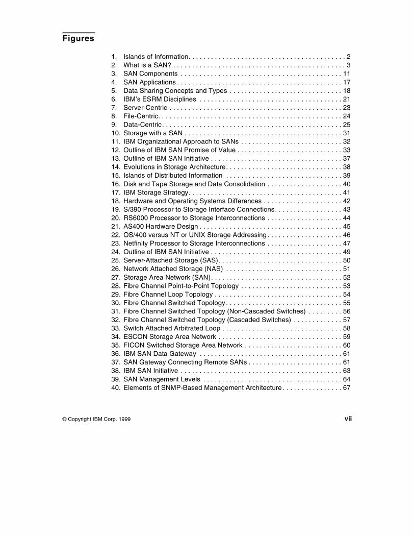
The advent of Client/Server computing, together with downsizing andrightsizing trends, created a new set of problems, such as escalatingmanagement costs for the desktop as well as new storage managementproblems. The information that was centralized in a host-centric environmentis now dispersed across the network and is often poorly managed andcontrolled. Storage devices are dispersed and connected to individualmachines; capacity increases must be planned machine by machine; storageacquired for one operating system platform often cannot be used on otherplatforms. We can visualize this environment as islands of information, asshown in Figure 1 on page 2. Information in one island is often hard to accessfrom other islands.
© Copyright IBM Corp. 1999 1
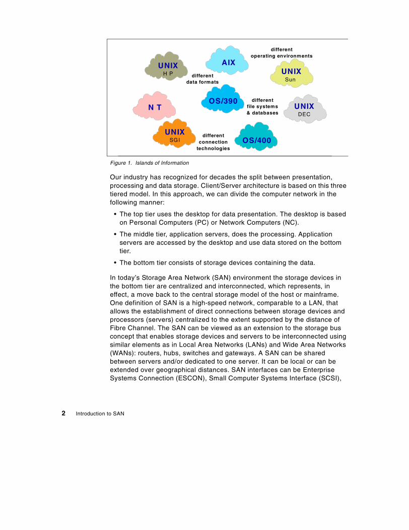
Figure 1. Islands of Information
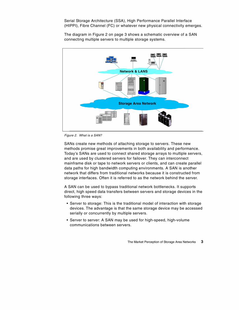
Our industry has recognized for decades the split between presentation,processing and data storage. Client/Server architecture is based on this threetiered model. In this approach, we can divide the computer network in thefollowing manner:
• The top tier uses the desktop for data presentation. The desktop is basedon Personal Computers (PC) or Network Computers (NC).
• The middle tier, application servers, does the processing. Applicationservers are accessed by the desktop and use data stored on the bottomtier.
• The bottom tier consists of storage devices containing the data.
In today’s Storage Area Network (SAN) environment the storage devices inthe bottom tier are centralized and interconnected, which represents, ineffect, a move back to the central storage model of the host or mainframe.One definition of SAN is a high-speed network, comparable to a LAN, thatallows the establishment of direct connections between storage devices andprocessors (servers) centralized to the extent supported by the distance ofFibre Channel. The SAN can be viewed as an extension to the storage busconcept that enables storage devices and servers to be interconnected usingsimilar elements as in Local Area Networks (LANs) and Wide Area Networks(WANs): routers, hubs, switches and gateways. A SAN can be sharedbetween servers and/or dedicated to one server. It can be local or can beextended over geographical distances. SAN interfaces can be EnterpriseSystems Connection (ESCON), Small Computer Systems Interface (SCSI),
H P
DEC
Sun
UNIX
OS/390
OS/400
AIX
UNIX
UNIX
N T
UNIXSGI
differentdata formats
differentoperating environments
differentfile systems& databases
differentconnection
technologies
2 Introduction to SAN
Serial Storage Architecture (SSA), High Performance Parallel Interface(HIPPI), Fibre Channel (FC) or whatever new physical connectivity emerges.
The diagram in Figure 2 on page 3 shows a schematic overview of a SANconnecting multiple servers to multiple storage systems.
Figure 2. What is a SAN?
SANs create new methods of attaching storage to servers. These newmethods promise great improvements in both availability and performance.Today’s SANs are used to connect shared storage arrays to multiple servers,and are used by clustered servers for failover. They can interconnectmainframe disk or tape to network servers or clients, and can create paralleldata paths for high bandwidth computing environments. A SAN is anothernetwork that differs from traditional networks because it is constructed fromstorage interfaces. Often it is referred to as the network behind the server.
A SAN can be used to bypass traditional network bottlenecks. It supportsdirect, high speed data transfers between servers and storage devices in thefollowing three ways:
• Server to storage: This is the traditional model of interaction with storagedevices. The advantage is that the same storage device may be accessedserially or concurrently by multiple servers.
• Server to server: A SAN may be used for high-speed, high-volumecommunications between servers.
Network & LANS
Storage Area Network
The Market Perception of Storage Area Networks 3
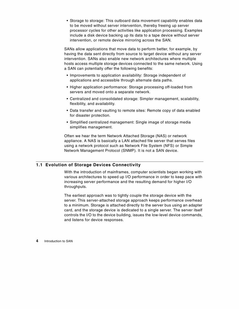
• Storage to storage: This outboard data movement capability enables datato be moved without server intervention, thereby freeing up serverprocessor cycles for other activities like application processing. Examplesinclude a disk device backing up its data to a tape device without serverintervention, or remote device mirroring across the SAN.
SANs allow applications that move data to perform better, for example, byhaving the data sent directly from source to target device without any serverintervention. SANs also enable new network architectures where multiplehosts access multiple storage devices connected to the same network. Usinga SAN can potentially offer the following benefits:
• Improvements to application availability: Storage independent ofapplications and accessible through alternate data paths.
• Higher application performance: Storage processing off-loaded fromservers and moved onto a separate network.
• Centralized and consolidated storage: Simpler management, scalability,flexibility, and availability.
• Data transfer and vaulting to remote sites: Remote copy of data enabledfor disaster protection.
• Simplified centralized management: Single image of storage mediasimplifies management.
Often we hear the term Network Attached Storage (NAS) or networkappliance. A NAS is basically a LAN attached file server that serves filesusing a network protocol such as Network File System (NFS) or SimpleNetwork Management Protocol (SNMP). It is not a SAN device.
1.1 Evolution of Storage Devices Connectivity
With the introduction of mainframes, computer scientists began working withvarious architectures to speed up I/O performance in order to keep pace withincreasing server performance and the resulting demand for higher I/Othroughputs.
The earliest approach was to tightly couple the storage device with theserver. This server-attached storage approach keeps performance overheadto a minimum. Storage is attached directly to the server bus using an adaptercard, and the storage device is dedicated to a single server. The server itselfcontrols the I/O to the device building, issues the low-level device commands,and listens for device responses.
4 Introduction to SAN
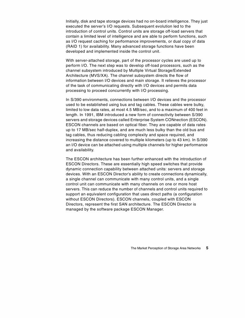
Initially, disk and tape storage devices had no on-board intelligence. They justexecuted the server’s I/O requests. Subsequent evolution led to theintroduction of control units. Control units are storage off-load servers thatcontain a limited level of intelligence and are able to perform functions, suchas I/O request caching for performance improvements, or dual copy of data(RAID 1) for availability. Many advanced storage functions have beendeveloped and implemented inside the control unit.
With server-attached storage, part of the processor cycles are used up toperform I/O. The next step was to develop off-load processors, such as thechannel subsystem introduced by Multiple Virtual Storage/ExtendedArchitecture (MVS/XA). The channel subsystem directs the flow ofinformation between I/O devices and main storage. It relieves the processorof the task of communicating directly with I/O devices and permits dataprocessing to proceed concurrently with I/O processing.
In S/390 environments, connections between I/O devices and the processorused to be established using bus and tag cables. These cables were bulky,limited to low data rates, at most 4.5 MB/sec, and to a maximum of 400 feet inlength. In 1991, IBM introduced a new form of connectivity between S/390servers and storage devices called Enterprise System CONnection (ESCON).ESCON channels are based on optical fiber. They are capable of data ratesup to 17 MB/sec half-duplex, and are much less bulky than the old bus andtag cables, thus reducing cabling complexity and space required, andincreasing the distance covered to multiple kilometers (up to 43 km). In S/390an I/O device can be attached using multiple channels for higher performanceand availability.
The ESCON architecture has been further enhanced with the introduction ofESCON Directors. These are essentially high speed switches that providedynamic connection capability between attached units: servers and storagedevices. With an ESCON Director's ability to create connections dynamically,a single channel can communicate with many control units, and a singlecontrol unit can communicate with many channels on one or more hostservers. This can reduce the number of channels and control units required tosupport an equivalent configuration that uses direct paths (a configurationwithout ESCON Directors). ESCON channels, coupled with ESCONDirectors, represent the first SAN architecture. The ESCON Director ismanaged by the software package ESCON Manager.
The Market Perception of Storage Area Networks 5

The S/390 FICON architecture is an enhancement of, rather than areplacement for, the existing ESCON architecture. As a SAN is Fibre Channelbased, FICON is a prerequisite for S/390 to fully participate in aheterogeneous SAN. FICON is a protocol that uses Fibre Channel fortransportation and is mapped in layer FC-4 (1.2.1.2, “Upper Layers” on page9) of Fibre Channel. FICON channels are capable of data rates up to100 MB/sec full duplex, extend the channel distance (up to 100 km), increasethe number of Control Unit images per link, increase the number of deviceaddresses per Control Unit link, and retain the topology and switchmanagement characteristics of ESCON. FICON architecture is fullycompatible with existing S/390 channel commands (CCWs) and programs.
FICON is currently in the standardization process as FC-SB-2. The currentstate of what has been disclosed can be found at www.t11.org (Click on Docs,then on Search, and enter FC-SB-2 as the search argument). There arenumerous occurrences representing different sections and/or presentations.
The architectures discussed above are used in S/390 environments and arediscussed in S/390 terms. Slightly different approaches were taken on otherplatforms, particularly in the UNIX and PC worlds.
The UNIX and PC world developed different connectivity standards. In the PCworld, the AT Attachment (ATA) interface was one of the first commonstandards.
The ATA interface includes Integrated Drive Electronics (IDE), Enhanced IDE(EIDE), and Ultra ATA (UltraATA). These were evolutions of the ATA standardthat added speed and functionality, up to 66 MB/sec with UltraATA. Althoughthe interface is backward compatible, there are many limitations, such as amaximum of four devices per interface, a maximum cable length of 10 inches,and many different types of read and write commands. The ATA interface ispopular because it is cheap, it is supported on all PC motherboards, and it isbackward compatible.
The Small Computer System Interface (SCSI) is a parallel interface. AlthoughSCSI protocols can be used on Fibre Channel (then called FCP) and SSAdevices, most people mean the parallel interface when they say SCSI. TheSCSI devices are connected to form a terminated bus (the bus is terminatedusing a terminator). The maximum cable length is 25 meters, and a maximumof 16 devices can be connected to a single SCSI bus. The SCSI protocol hasmany configuration options for error handling and supports both disconnectand reconnect to devices and multiple initiator requests. Usually a hostcomputer is an initiator. Multiple initiator support allows multiple hosts toattach to the same devices and is used in support of clustered configurations.
6 Introduction to SAN
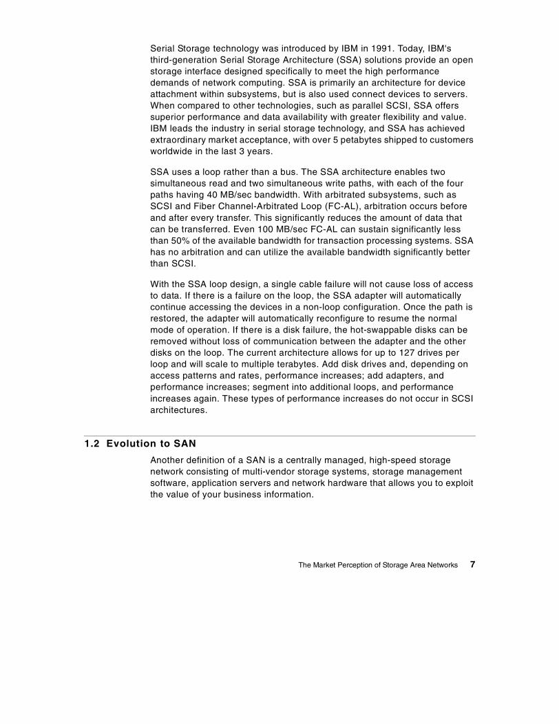
Serial Storage technology was introduced by IBM in 1991. Today, IBM'sthird-generation Serial Storage Architecture (SSA) solutions provide an openstorage interface designed specifically to meet the high performancedemands of network computing. SSA is primarily an architecture for deviceattachment within subsystems, but is also used connect devices to servers.When compared to other technologies, such as parallel SCSI, SSA offerssuperior performance and data availability with greater flexibility and value.IBM leads the industry in serial storage technology, and SSA has achievedextraordinary market acceptance, with over 5 petabytes shipped to customersworldwide in the last 3 years.
SSA uses a loop rather than a bus. The SSA architecture enables twosimultaneous read and two simultaneous write paths, with each of the fourpaths having 40 MB/sec bandwidth. With arbitrated subsystems, such asSCSI and Fiber Channel-Arbitrated Loop (FC-AL), arbitration occurs beforeand after every transfer. This significantly reduces the amount of data thatcan be transferred. Even 100 MB/sec FC-AL can sustain significantly lessthan 50% of the available bandwidth for transaction processing systems. SSAhas no arbitration and can utilize the available bandwidth significantly betterthan SCSI.
With the SSA loop design, a single cable failure will not cause loss of accessto data. If there is a failure on the loop, the SSA adapter will automaticallycontinue accessing the devices in a non-loop configuration. Once the path isrestored, the adapter will automatically reconfigure to resume the normalmode of operation. If there is a disk failure, the hot-swappable disks can beremoved without loss of communication between the adapter and the otherdisks on the loop. The current architecture allows for up to 127 drives perloop and will scale to multiple terabytes. Add disk drives and, depending onaccess patterns and rates, performance increases; add adapters, andperformance increases; segment into additional loops, and performanceincreases again. These types of performance increases do not occur in SCSIarchitectures.
1.2 Evolution to SAN
Another definition of a SAN is a centrally managed, high-speed storagenetwork consisting of multi-vendor storage systems, storage managementsoftware, application servers and network hardware that allows you to exploitthe value of your business information.
The Market Perception of Storage Area Networks 7

In the following sections we will present an overview of the basic SAN storageconcepts and building blocks that enable the vision stated above to become areality.
1.2.1 Fibre Channel ArchitectureToday, the industry considers Fibre Channel (FC) as the architecture onwhich most SAN implementations will be built. Fibre Channel is a technologystandard that allows data to be transferred from one network node to anotherat very high speeds. Current implementations transfer data at 100 MB/sec.The 200 MB/sec and 400 MB/sec data rates have already been tested. Thisstandard is backed by a consortium of industry vendors and has beenaccredited by the American National Standards Institute (ANSI). Manyproducts are now on the market that take advantage of FC’s high-speed,high-availability characteristics.
Note that the word Fibre in Fibre Channel is spelled in the French way ratherthan the American way. This is because the interconnections between nodesare not necessarily based on fiber optics, but can also be based on coppercables.
Some people refer to Fibre Channel architecture as the Fibre version ofSCSI. Fibre Channel is an architecture used to carry IPI traffic, IP traffic,FICON traffic, FCP (SCSI) traffic, and possibly traffic using other protocols,all at the same level on the standard FC transport. An analogy could beethernet, where IP, NetBOIS, and SNA are all used simultaneously over asingle ethernet adapter, since these are all protocols with mappings toethernet. Similarly, there are many protocols mapped onto FC.
FICON is expected to be the standard protocol for S/390, and FCP is theexpected standard protocol for the non-S/390 systems, both using FibreChannel architecture to carry the traffic.
In the following sections, we will introduce some basic Fibre Channelconcepts, starting with the physical layer and proceeding to define theservices offered.
8 Introduction to SAN

1.2.1.1 Physical LayerFibre Channel is structured in independent layers, as are other networkingprotocols. There are five layers, where 0 is the lowest layer. The Physicallayers are 0 to 2.
• FC-0 defines physical media and transmission rates. These include cablesand connectors, drivers, transmitters, and receivers.
• FC-1 defines encoding schemes. These are used to synchronize data fortransmission.
• FC-2 defines the framing protocol and flow control. This protocol isself-configuring and supports point-to-point, arbitrated loop, and switchedtopologies.
1.2.1.2 Upper LayersFibre Channel is a transport service that moves data fast and reliablybetween nodes. The two upper layers enhance the functionality of FibreChannel and provide common implementations for interoperability.
• FC-3 defines common services for nodes. One defined service ismulticast, to deliver one transmission to multiple destinations.
• FC-4 defines upper layer protocol mapping. Protocols such as FCP(SCSI), FICON, and IP can be mapped to the Fibre Channel transportservice.
1.2.1.3 TopologiesFibre Channel interconnects nodes using three physical topologies that canhave variants. Topologies include:
• Point-to-point — The point-to-point topology consists of a singleconnection between two nodes. All the bandwidth is dedicated for thesetwo nodes.
• Loop — In the loop topology, the bandwidth is shared between all thenodes connected to the loop. The loop can be wired node-to-node;however, if a node fails or is not powered on, the loop is out of operation.This is overcome by using a hub. A hub opens the loop when a new nodeis connected and closes it when a node disconnects.
• Switched — A switch allows multiple concurrent connections betweennodes. There can be two types of switches, circuit switches and frameswitches. Circuit switches establish a dedicated connection between twonodes, whereas frame switches route frames between nodes andestablish the connection only when needed. A switch can handle allprotocols as it does not look at the Fibre Channel layer FC-4.
The Market Perception of Storage Area Networks 9

1.2.1.4 Classes of ServiceFibre Channel provides a logical system of communication called Class ofService that is allocated by various Login protocols. The following fiveclasses of service are defined:
• Class 1 — Acknowledged Connection Service
Dedicates connections through fabric equivalent of a dedicated physicallink and delivers frames with acknowledgment in the same order astransmitted.
• Class 2 — Acknowledged Connectionless Service
Multiplexes frames from multiple sources with acknowledgment. Frameorder is not guaranteed.
• Class 3 — Unacknowledged Connectionless Service
As class 2, without frame acknowledgment. Flow has to be controlled atbuffer level.
• Class 4 — Fractional Bandwidth Connection Oriented Service
As class 1, but with only a minimum of bandwidth guaranteed. If sufficientbandwidth is available, class 2 and 3 frames will share connections.
• Class 6 — Simplex Connection Service
As class 1, but also provides multicast and preemption.
1.3 SAN Components
As mentioned earlier, the industry considers Fibre Channel as thearchitecture on which most SAN implementations will be built, with FICON asthe standard protocol for S/390 systems, and FCP as the standard protocolfor non-S/390 systems. Based on this perception, the SAN componentsdescribed in the following sections will be Fibre Channel based (see Figure 3on page 11).
10 Introduction to SAN

Figure 3. SAN Components
1.3.1 SAN ServersThe server Infrastructure is the underlying reason for all SAN solutions.This infrastructure includes a mix of server platforms such as Windows NT,UNIX (various flavors) and OS/390. With initiatives such as ServerConsolidation and e-Business, the need for SAN will increase. Although theearly SAN solutions only supported homogeneous environments, SAN willevolve into a truly heterogeneous environment.
1.3.2 SAN StorageThe storage infrastructure is the foundation on which information relies andtherefore must support a company’s business objectives and business model.In this environment, simply deploying more and faster storage devices is notenough; a new kind of infrastructure is needed, one that provides moreenhanced network availability, data accessibility, and system manageabilitythan is provided by today’s infrastructure.
SwitchesGateways
Hubs
Routers
HeterogeneousServers
SharedStorageDevices
Bridges
The Market Perception of Storage Area Networks 11

The SAN meets this challenge. The SAN liberates the storage device, so it isnot on a particular server bus, and attaches it directly to the network. In otherwords, storage is externalized and functionally distributed across theorganization. The SAN also enables the centralizing of storage devices andthe clustering of servers, which makes for easier and less expensiveadministration.
1.3.3 SAN InterconnectsThe first element that must be considered in any SAN implementation is theconnectivity of storage and server components using technologies such asFibre Channel. The components listed below have typically been used forLAN and WAN implementations. SANs, like LANs, interconnect the storageinterfaces together into many network configurations and across longdistances.
Much of the terminology used for SAN has its origin in IP networkterminology. In some cases, the industry and IBM use different terms thatmean the same thing, and in some cases, mean different things. Forexample, after reading the sections 1.3.3.10, “Bridges” on page 15 and1.3.3.11, “Gateways” on page 15, you will find that the IBM SAN DataGateway is really a bridge, not a gateway.
1.3.3.1 Cables and ConnectorsAs with parallel SCSI and traditionalnetworking, there are different types ofcables of various lengths for use in a FibreChannel configuration. Two types of cablesare supported: copper and optical (fiber).Copper cables are used for short distances(up to 30m) and can be identified by theirDB9 (9-pin) connector. Fiber cables come in two distinct types: Multi-Modefiber (MMF) for short distances (up to 2 km), and Single-Mode Fiber (SMF) forlonger distances (up to 10km). IBM will support the following distances forFCP:
Diameter(Microns) Mode Laser type Distance
9 Single-mode Longwave <=10 km
50 Multi-mode Shortwave <=500 m
62.5 Multi-mode Shortwave <=175 m
12 Introduction to SAN
In addition, connectors (see 1.3.3.3, “Gigabit Interface Converters (GBIC)” onpage 13) and cable adapters (see 1.3.3.4, “Media Interface Adapters (MIA)”on page 13) have been developed that allow the interconnection of fiber opticbased adapters with copper based devices.
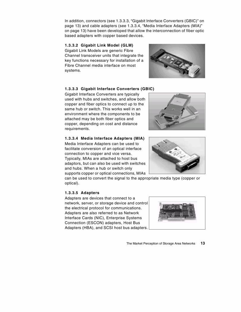
1.3.3.2 Gigabit Link Model (GLM)Gigabit Link Models are generic FibreChannel transceiver units that integrate thekey functions necessary for installation of aFibre Channel media interface on mostsystems.
1.3.3.3 Gigabit Interface Converters (GBIC)Gigabit Interface Converters are typicallyused with hubs and switches, and allow bothcopper and fiber optics to connect up to thesame hub or switch. This works well in anenvironment where the components to beattached may be both fiber optics andcopper, depending on cost and distancerequirements.
1.3.3.4 Media Interface Adapters (MIA)Media Interface Adapters can be used tofacilitate conversion of an optical interfaceconnection to copper and vice versa.Typically, MIAs are attached to host busadaptors, but can also be used with switchesand hubs. When a hub or switch onlysupports copper or optical connections, MIAscan be used to convert the signal to the appropriate media type (copper oroptical).
1.3.3.5 AdaptersAdapters are devices that connect to anetwork, server, or storage device and controlthe electrical protocol for communications.Adapters are also referred to as NetworkInterface Cards (NIC), Enterprise SystemsConnection (ESCON) adapters, Host BusAdapters (HBA), and SCSI host bus adapters.
The Market Perception of Storage Area Networks 13
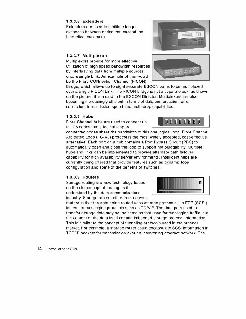
1.3.3.6 ExtendersExtenders are used to facilitate longerdistances between nodes that exceed thetheoretical maximum.
1.3.3.7 MultiplexorsMultiplexors provide for more effectiveutilization of high speed bandwidth resourcesby interleaving data from multiple sourcesonto a single Link. An example of this wouldbe the FIbre CONnection Channel (FICON)Bridge, which allows up to eight separate ESCON paths to be multiplexedover a single FICON Link. The FICON bridge is not a separate box; as shownon the picture, it is a card in the ESCON Director. Multiplexors are alsobecoming increasingly efficient in terms of data compression, errorcorrection, transmission speed and multi-drop capabilities.
1.3.3.8 HubsFibre Channel hubs are used to connect upto 126 nodes into a logical loop. Allconnected nodes share the bandwidth of this one logical loop. Fibre ChannelArbitrated Loop (FC-AL) protocol is the most widely accepted, cost-effectivealternative. Each port on a hub contains a Port Bypass Circuit (PBC) toautomatically open and close the loop to support hot pluggability. Multiplehubs and links can be implemented to provide alternate path failovercapability for high availability server environments. Intelligent hubs arecurrently being offered that provide features such as dynamic loopconfiguration and some of the benefits of switches.
1.3.3.9 RoutersStorage routing is a new technology basedon the old concept of routing as it isunderstood by the data communicationsindustry. Storage routers differ from networkrouters in that the data being routed uses storage protocols like FCP (SCSI)instead of messaging protocols such as TCP/IP. The data path used totransfer storage data may be the same as that used for messaging traffic, butthe content of the data itself contain imbedded storage protocol information.This is similar to the concept of tunneling protocols used in the broadermarket. For example, a storage router could encapsulate SCSI information inTCP/IP packets for transmission over an intervening ethernet network. The
14 Introduction to SAN
term routing implies data transfers over differing transmission media andaddressing schemes. As a combination of communications and storagechannel capabilities, Fibre Channel represents the first opportunity to applycommunication techniques, such as routing, to storage traffic.
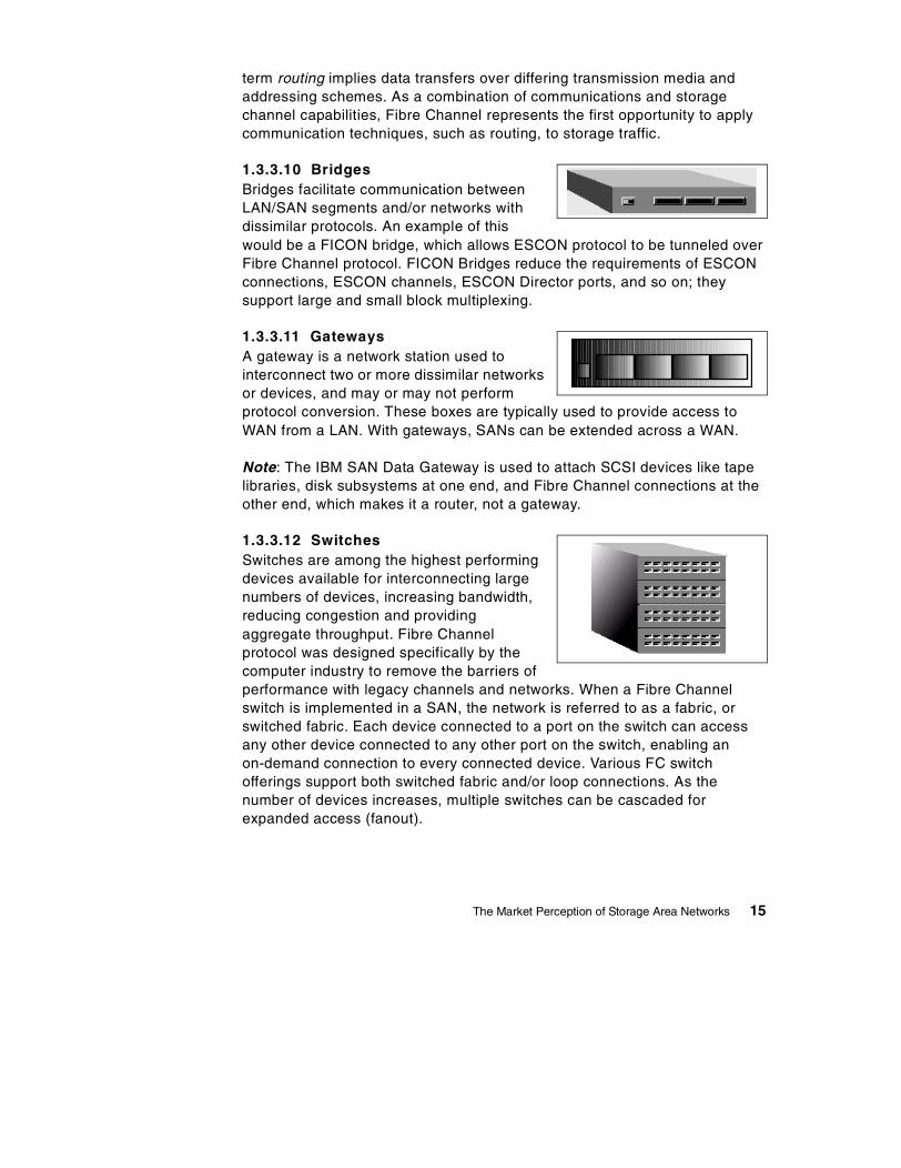
1.3.3.10 BridgesBridges facilitate communication betweenLAN/SAN segments and/or networks withdissimilar protocols. An example of thiswould be a FICON bridge, which allows ESCON protocol to be tunneled overFibre Channel protocol. FICON Bridges reduce the requirements of ESCONconnections, ESCON channels, ESCON Director ports, and so on; theysupport large and small block multiplexing.
1.3.3.11 GatewaysA gateway is a network station used tointerconnect two or more dissimilar networksor devices, and may or may not performprotocol conversion. These boxes are typically used to provide access toWAN from a LAN. With gateways, SANs can be extended across a WAN.
Note: The IBM SAN Data Gateway is used to attach SCSI devices like tapelibraries, disk subsystems at one end, and Fibre Channel connections at theother end, which makes it a router, not a gateway.
1.3.3.12 SwitchesSwitches are among the highest performingdevices available for interconnecting largenumbers of devices, increasing bandwidth,reducing congestion and providingaggregate throughput. Fibre Channelprotocol was designed specifically by thecomputer industry to remove the barriers ofperformance with legacy channels and networks. When a Fibre Channelswitch is implemented in a SAN, the network is referred to as a fabric, orswitched fabric. Each device connected to a port on the switch can accessany other device connected to any other port on the switch, enabling anon-demand connection to every connected device. Various FC switchofferings support both switched fabric and/or loop connections. As thenumber of devices increases, multiple switches can be cascaded forexpanded access (fanout).
The Market Perception of Storage Area Networks 15

As switches allow any-to-any connections, the switch and managementsoftware can restrict which other ports a specific port can connect to. This iscalled port zoning.
1.3.3.13 DirectorsWhen ESCON was announced, the switches were named directors, as theyincluded high availability and other features; for example, dual power supply,not included in traditional switches.
ESCONESCON transfers data in half duplex mode at a transfer rate of 17 MB/sec.The directors provide dynamic or static connections between attachedchannels, control units, devices, and other ESCON directors. ESCONDirectors provide single-link distances up to 3 km for multi-mode fiber and20 km for single-mode fiber.
The ESCON director supports the FICON bridge card mentioned in 1.3.3.10,“Bridges” on page 15. Using the FICON bridge, an S/390 system can, througha FICON channel, communicate with ESCON control units and devicesattached to the director.
FICONFICON transfers data in full duplex mode at a rate of 100 MB/sec. The FICONdirector is a regular Fibre Channel switch with some additional features. Itprovides connections between FICON channels and control units or deviceswith FICON interfaces. FICON Directors provide single-link distances up to550 meters for multi-mode fiber (50 or 62.5 micron) and 10 km (20 km withRPQ) for single-mode fiber (9 micron).
1.3.4 SAN ApplicationsStorage Area Networks (SANs) enable a number of applications that provideenhanced performance, manageability, and scalability to IT infrastructures.These applications are being driven by parts technology capabilities, and astechnology matures over time, we are likely to see more and moreapplications in the future.
Figure 4 on page 17 Illustrates the various SAN Applications.
16 Introduction to SAN

Figure 4. SAN Applications
1.3.4.1 Shared Repository and Data SharingSANs enable storage to be externalized from the server and centralized, andin so doing, allow data to be shared among multiple host servers withoutimpacting system performance. The term data sharing describes the accessof common data for processing by multiple computer platforms or servers.Data sharing can be between platforms that are similar or different; this isalso referred to as homogeneous and heterogeneous data sharing.
Figure 5 on page 18 shows the data sharing concepts and types of datasharing.
SANApplications
DataProtection
SharedRepository
Clustering
DataVaulting &Backups
DataInterchange
DisasterRecovery
DataSharing
NetworkArchitechture
The Market Perception of Storage Area Networks 17

Figure 5. Data Sharing Concepts and Types
Storage SharingWith storage sharing, two or more homogeneous or heterogeneous serversshare a single storage subsystem whose capacity has been physicallypartioned so that each attached server can access only the units allocated toit. Multiple servers can own the same partition, but this is possible only withhomogeneous servers such as in a S/390 Parallel Sysplex configuration.
For more information on storage sharing, see, for example, IBM Magstar3494 Tape Libraries: A Practical Guide, SG24-4632; IBM Versatile StorageServer, SG24-2221; and Implementing the Enterprise Storage Server in YourEnvironment, SG24-5420.
Data-Copy SharingData-copy sharing allows different platforms to access the same data bysending a copy of the data from one platform to the other. There are twoapproaches to data-copy sharing between platforms: flat file transfer andpiping.
For more information on data-copy sharing, see Data Sharing: ImplementingCopy-Sharing Solutions Among Heterogeneous Systems, SG24-4120.
"True" Data SharingIn true data sharing, only one copy of the data is accessed by multipleplatforms, whether homogeneous or heterogeneous. Every platform attachedhas read and write access to the single copy of data.
Storage Subsystem-BasedSharing
Storage Sharing Data-Copy Sharing "True" Data Sharing
Homogeneous Heterogeneous
18 Introduction to SAN

In today’s computing environment, true data sharing exists only onhomogeneous platforms, for example, in an OS/390 Parallel Sysplexconfiguration. Another example of true data sharing is a RS/6000 clusterconfiguration with shared-disk architecture using software such as DB2Parallel Edition or Oracle Parallel server to guarantee data integrity.
1.3.4.2 Network ArchitectureThe messaging network like an Ethernet, is often defined as the primarynetwork, in which case the SAN can be defined as the secondary network or,as some vendors describe it, the network behind the server. This networkarchitecture enables centralized storage by using similar interconnecttechnologies used by LANs and WANs: routers, hubs, switches and gateways— and allows the SAN to be local or remote, shared or dedicated. Thisprovides significant improvements in availability, performance, and scalabilityof the storage resources.
1.3.4.3 Data Vaulting and Data BackupIn most present day scenarios of data vaulting and data backups to near-lineor off-line storage, the primary network, LAN or WAN, is the medium used fortransferring both the server, file and database server, or end-user client datato the storage media. SANs enable data vaulting and data backup operationson servers to be faster and independent of the primary network, which hasled to the delivery of new data movement applications like LAN-less backupand server-free backup.
1.3.4.4 Data InterchangeToday, data interchange primarily involves moving data from one storagesystem to another. However, the SAN roadmaps of many vendors show datainterchange between different heterogeneous systems as one of the goals forSAN. This is primarily because different platforms store and access datausing different methods for data encoding and file structures. Trueheterogeneous data interchange can only be achieved when these differentfile systems allow for transparent data access.
1.3.4.5 ClusteringClustering is usually thought of as a server process providing failover to aredundant server, or as scalable processing using multiple servers in parallel.In a cluster environment, SAN provides the data pipe, allowing storage to beshared.
The Market Perception of Storage Area Networks 19

1.3.4.6 Data Protection and Disaster RecoveryThe highest level of application availability requires avoiding traditionalrecovery techniques, such as recovery from tape. Instead, new techniquesthat duplicate systems and data must be architected so that, upon the eventof a failure, another system is ready to go. Techniques to duplicate the dataportion include remote copy and warm standby techniques.
Data protection in environments with the highest level of availability is bestachieved by creating second redundant copies of the data by storagemirroring, remote cluster storage, Peer-to-Peer Remote Copy (PPRC) andExtended Remote Copy (XRC), Concurrent Copy, and other High Availability(HA) data protection solutions. These are then used for disaster recoverysituations. SAN any-to-any connectivity enables these redundantdata/storage solutions to be dynamic and not impact the primary network andservers, including serialization and coherency control.
For more information on the copy services mentioned above, see Planning forIBM Remote Copy, SG24-2595; and IBM Enterprise Storage Server,SG24-5465.
Subsystem local copy services, such as SnapShot Copy or Flashcopy, assistin creating copies in high availability environments and for traditional backupand therefore are not directly applicable to disaster recovery or part of SAN.
1.3.5 Managing the SANIn order to achieve the various benefits and features of SANs, likeperformance, availability, cost, scalability, and interoperability, theinfrastructure (switches, routers, and so on) of the SANs, as well as theattached storage systems, must be effectively managed. To simplify SANmanagement, SAN vendors need to adapt Simple Network ManagementProtocol (SNMP), Web Based Enterprise Management (WBEM) andEnterprise Storage Resources Management (ESRM) type standards toconsistently monitor, alert and manage all components of the SAN. There isalso a need for managing partitions of the SAN from a central console. Thebig challenge is to ensure that all components are interoperable and workwith the various management software packages.
Management of the SAN can be divided into various disciplines defined inEnterprise Storage Resources Management (ESRM). These disciplinesshould be implemented across all heterogeneous resources connected to theSAN, with the objective of providing one common user interface across allresources.
20 Introduction to SAN

Figure 6 on page 21 highlights the IBM’s ESRM disciplines.
Figure 6. IBM’s ESRM Disciplines
1.3.5.1 Asset ManagementAsset management addresses the need to discover resources, recognize theresources, and tie them into the rest of the topology. The output is a completeinventory list of the assets that include manufacturer, model information,software and licence information.
1.3.5.2 Capacity ManagementCapacity management addresses the sizing of the SAN, for example, howmany switches of which size are needed. It also addresses the need to knowabout free space/slots, unassigned volumes, free space in the assignedvolumes, number of backups, number of tapes, percent utilization, andpercentage free/scratch.
NetworkmanagementApplicationsmanagementStoragemanagementOperatingSystemsmanagementChangemanagementProblemmanagementSoftwaredistributionPrintermanagementHelp deskWebmanagement
SystemsManagementDisciplines
StorageManagementDisciplines
Backup/restoreArchive/retrieveSpace usagemanagementDisasterrecoveryStorageresourcemanagementAuthorizationAccounting andchargeout
StorageResource
ManagementDisciplines
AssetmanagementCapacitymanagementConfigurationmanagementData/device/mediamigrationEventmanagement andalertsPerformancemanagementPolicymanagementRemovable mediamanagement
The Market Perception of Storage Area Networks 21

1.3.5.3 Configuration ManagementConfiguration management addresses the need for current logical andphysical configuration data, ports utilization data, and device driver data tosupport the ability to set SAN configurations based on business requirementsof high availability and connectivity. It also addresses the need of integratingthe configuration of storage resources with configuration of the server’slogical view of them; for example, whoever configures an Enterprise StorageServer affects what must ultimately be configured at the server.
1.3.5.4 Performance ManagementPerformance management addresses the need to improve performance ofthe SAN and do problem isolation at all levels — device hardware andsoftware interfaces, application, and even file level. This approach requirescommon platform-independent access standards across all SAN solutions.
1.3.5.5 Availability ManagementAvailability management addresses the need to prevent failure, correctproblems as they happen, and provide warning of the key events long beforethey become critical. For example, in the event of a path failure, anavailability management function might be to determine a link or othercomponent failed, assign an alternate path, and page the engineer to repairthe failing component, keeping the systems up through the entire process.
1.4 Where We Are Today
In the following sections we discuss the SAN scene today.
1.4.1 Server Attached StorageSAN excitement is rampant; after all, the promise of an any-to-any nirvana ispretty compelling. However, most analysts agree, and history bears witnessto this truth, that both technology maturity and mainstream adoption are anevolutionary process. With that in mind, it is best to see where we have comefrom in order to better understand where we are today, and where we areheading in the future. Figure 7 on page 23 highlights the limitations of ServerAttached Storage.
22 Introduction to SAN
.
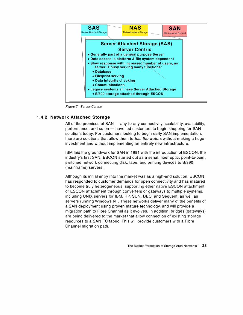
Figure 7. Server-Centric
1.4.2 Network Attached StorageAll of the promises of SAN — any-to-any connectivity, scalability, availability,performance, and so on — have led customers to begin shopping for SANsolutions today. For customers looking to begin early SAN implementation,there are solutions that allow them to test the waters without making a hugeinvestment and without implementing an entirely new infrastructure.
IBM laid the groundwork for SAN in 1991 with the introduction of ESCON, theindustry's first SAN. ESCON started out as a serial, fiber optic, point-to-pointswitched network connecting disk, tape, and printing devices to S/390(mainframe) servers.
Although its initial entry into the market was as a high-end solution, ESCONhas responded to customer demands for open connectivity and has maturedto become truly heterogeneous, supporting ether native ESCON attachmentor ESCON attachment through converters or gateways to multiple systems,including UNIX servers for IBM, HP, SUN, DEC, and Sequent, as well asservers running Windows NT. These networks deliver many of the benefits ofa SAN deployment using proven mature technology, and will provide amigration path to Fibre Channel as it evolves. In addition, bridges (gateways)are being delivered to the market that allow connection of existing storageresources to a SAN FC fabric. This will provide customers with a FibreChannel migration path.
Server Attached Storage (SAS)Server Centric
Generally part of a general purpose ServerData sccess is platform & file system dependentSlow response with increased number of users, as
server is busy serving many functions:DatabaseFile/print servingData integrity checkingCommunications
Legacy systems all have Server Attached StorageS/390 storage attached through ESCON
NASNetwork Attach Storage
SANStorage Area Network
SASServer Attached Storage
The Market Perception of Storage Area Networks 23

Figure 8. File-Centric
1.4.3 Data-CentricAs depicted in Figure 9 on page 25, there are some major obstacles whichneed to be overcome to reach a true Data Centric Storage Area Network.Today, IBM is aggressively working with the industry to use its years ofexperience and expertise to deliver the next generation SAN. IBM’saccomplishments include the following:
• Invented System Managed Storage (SMS) in the 1970's
• Gained SAN management expertise with ESCON Manager
• Has extensive experience with Storage Management software (ADSM)
• Was involved in the initial definition of the Fibre Channel initiative, and isactive in the SAN standards organizations, including the Fibre ChannelAssociation and the Storage Networking Industry Association.
• Is aggressively working with the industry to leverage its years ofexperience, expertise, and intellectual property in first-generation SANtechnology and SAN management in the S/390 world to deliversecond-generation SANs, enabling all the benefits of a switched networktopology in today’s open environment.
• Has already been established in the intelligent server market (VersatileStorage Server and Enterprise Storage server)
• Has an Enterprise Storage Resource Management framework (StorWatch)
Network Attached Storage (NAS)File-Centric
Dedicated File ServerFile Server connected to a messaging protocol LANStorage partioningData copy-sharing between heterogeneous serversData sharing between homogeneous servers
NASNetwork Attach Storage
SANStorage Area Network
SASServer Attached Storage
24 Introduction to SAN

• Has a world-leading research and development (R&D) organization (IBMResearch)
• Has a long record of experience and leadership in storage, servers,networking, systems management, and services
Figure 9. Data-Centric
Storage Area Network (SAN)Data-Centric
Server/storage independenceCombines high performance of I/O Channel withconnectivity of a networkHighly scalableCentralized managementNo conflict with network trafficHigh availability though SAN technologiesLAN-less and server-free backupDevice poolingNeeds standards in many areas
SASServer Attached Storage
NASNetwork Attach Storage
SANStorage Area Network
NASNetwork Attach Storage
SANStorage Area Network
SASServer Attached Storage
The Market Perception of Storage Area Networks 25

26 Introduction to SAN
Chapter 2. The IBM SAN Initiative
The evolution of Information Technology (IT), coupled with the explosion ofthe Internet as a means for individuals and companies to communicate andexchange information, has led to the rise of a new business model that iscommonly referred to as e-business, and in some cases e-commerce.
2.1 New Paradigms: e-Business
e-business is becoming a strategic imperative for many companiesworldwide. The driving force behind this is the need to cut costs, therebyimproving profits. A second but equally important reason is the need anddesire to expand a company’s reach. e-business allows you to communicateeasily and cheaply with customers anytime, anywhere.
e-business is changing traditional business models because it isnetwork-centric, global, and data-intensive. The foundation of e-business isthe network itself, and the most widely used network today is the Internet.The Internet is global in reach as it can be accessed from anywhere aroundthe globe. The term data-intensive describes the fact that all electronictransactions can be stored for processing and subsequent analysis. Today weare faced with an explosion of data generated by e-business applications.This data must be stored and managed appropriately. There is also arequirement to distill information out of raw data using data miningapplications.
These industry trends are driving the requirement for more flexible andreliable access to data. The data resides on storage devices. This is drivingthe requirement for SANs. Enterprise Resource Planning (ERP), data miningand decision support applications are also driving the requirement for SANsbecause the data involved has to be accessed from or copied betweenheterogeneous environments.
In the following sections we will discuss the technology trends driving storageevolution and the development of SANs.
2.1.1 Storage Technology TrendsThere are many trends driving the evolution of storage and storagemanagement. Heterogeneous IT environments are here to stay. Companiesand IT departments buy applications and often accept the applicationvendor’s suggested platform. This leads to having many different platforms inthe IT Shop.
© Copyright IBM Corp. 1999 27

This leads to a second trend, recentralization of server and storage assets.This trend is driven by the rightsizing and rehosting trends, as opposed to thepure downsizing practiced throughout the 1990s. Storage capacity is alsogrowing, and increasing amounts of data are stored in distributedenvironments. This leads to issues related to appropriate management andcontrol of the underlying storage resources.
The advent of the Internet and 24x7 accessibility requirements have led togreater emphasis being put on the availability of storage resources and thereduction of windows in which to perform necessary storage managementoperations.
Another important trend is the advent of the Virtual resource. A virtualresource is a black box that performs some kind of function or servicetransparently. The system using the virtual resource continues to function asif it were using a real resource, but the underlying technology in the black boxmay be completely different from the original technology.
The above issues lead to the trends that are driving SANs, as discussed inthe following section.
2.1.2 Trends Driving SANsThe trends driving the evolution of storage are also the trends that are drivingthe evolution of SANs. Data is the basis for most of the business valuecreated by information technology, and the storage infrastructure is thefoundation upon which data relies.
The storage infrastructure needs to support business objectives and newemerging business models. Some of the requirements of today’s companiesare:
• Unlimited and just-in-time scalability. Businesses require the capability toflexibly adapt to rapidly changing demands for storage resources.
• Flexible and heterogeneous connectivity. The storage resource must beable to support whatever platforms are within the environment. This isessentially an investment protection requirement that allows you toconfigure a storage resource for one set of systems and subsequentlyconfigure part of the capacity to other systems on an as-needed basis.
• Secure transactions and data transfer. This is a security and integrityrequirement aiming to guarantee that data from one application or systemdoes not become overlaid or corrupted by other applications or systems.Authorization also require the ability to fence off one system’s data toother systems.
28 Introduction to SAN

• 24x7 response and availability. This is an availability requirement thatimplies both protection against media failure, possibly using RAIDtechnologies, as well as ease of data migration between devices withoutinterrupting application processing.
Current technologies, especially SCSI technology, have limitations in terms ofdistance, addressability, and performance. Typically, SCSI devices can beconnected to a limited number of systems, and reconnecting devices todifferent systems is a manual operation that requires unplugging andreplugging SCSIs to different machines.
SANs mirror the e-business model for storage. They hold the followingpromises:
• Storage consolidation. Today, storage is mostly server-attached andcannot be easily moved. Storage consolidation holds the promise ofattaching storage to multiple servers concurrently and leveraginginvestments.
• Storage sharing. Once storage is attached to multiple servers, it can bepartitioned or shared between servers.
• Data sharing. Can be enabled if storage is shared and the software toprovide the necessary locking and synchronization functions exists.
• Improvements to backup and recovery processes. Attaching disk and tapedevices to the same SAN allows for fast data movement between deviceswhich provides enhanced backup and recovery capabilities.
• Disaster tolerance. The ability to continue operations without interruptioneven in the case of a disaster at one location is enabled by remotemirroring of data.
• Higher availability. SAN any-to-any connectivity provides higheravailability by enabling mirroring, alternate pathing, etc.
• Improved performance. Enhanced performance is enabled because ofmore efficient transport mechanisms such as Fibre Channel.
• Selection of best in class products. Products from multiple vendors canoperate together, and storage purchase decisions can be madeindependent of servers.
• Simplified migration to new technologies. Facilitate both data and storagesubsystem migration from one system to another without interruptingservice.
• Centralized management. The ability to manage multiple heterogeneousboxes from one single point of control.
The IBM SAN Initiative 29

Most of the functions described above are not available today, as we will seein the following section.
2.1.3 SAN Status TodayToday we are early in the SAN technology life cycle. The technology is stillrelatively immature and there is also a lack of accepted industrial standards.Data integrity is an important issue. Today, many current implementations relyon the physical wiring only for security, but other security schemes are beingdeveloped. For example, some vendors are developing a logical partitioningapproach called zoning.
Most of the SAN solutions on the market today are limited in scope andrestricted to specific applications. Interoperability is not possible in many ofthese solutions. Some of the currently available solutions are:
• Backup and recovery• Storage consolidation• Data replication• Virtual storage resources
Most of the SAN management packages available today are limited in scopeto the management of one particular element or aspect of the SAN. Most ofthese solutions are proprietary and are lacking in interoperability.
We will now discuss what the industry requires for SANs to enter themainstream of computing and deliver on their true promise.
2.1.4 SAN EvolutionThe first requirement is the definition of standards. Standards are the base forinteroperability of devices and software from different vendors. The SNIAorganization is active in defining these standards. Most of the players in theSAN industry recognize the need for standards, as these are the basis forwide acceptance of SANs. Widely accepted standards allow forheterogeneous, cross-platform, multi-vendor deployment of SAN solutions.
There is a requirement for the expansion of the scope of SANs toenterprise-wide environments, with particular emphasis on multi-platformconnectivity. True cross-platform data sharing solutions, as opposed to datapartitioning solutions, are also a requirement. Security and access controlneed to be improved to guarantee data integrity. There is a requirement forcomplex, end-to-end SAN management from a single point. Last, butprobably most important of all, SANs should evolve to support an open,standards-based environment. Figure 10 on page 31 illustrates a SAN
30 Introduction to SAN

to which multiple systems can connect. SAN is the key to moving digitalinformation from operating system islands to universal access.
Figure 10. Storage with a SAN
Having discussed the market requirements, in the following section we willdiscuss how IBM is responding to the challenge.
2.2 The IBM Response
IBM: A storage area network (SAN) is a dedicated, centrally managed,secure information infrastructure, which enables any-to-anyinterconnection of servers and storage systems.Source: www.storage.ibm.com/ibmsan/basics.htm
IBM has recognized industry needs and is addressing them with the IBM SANInitiative. This initiative draws upon decades of IBM leadership in enterprisecomputing across all platforms. IBM has established a cross-division taskforce to coordinate and leverage the experiences across all divisions. IBMalso closely cooperates with standards bodies to define industry standardsand promote interoperability across multiple vendor devices.
AIXUNIX
Sun
WindowsNT
UNIXH P
UNIXDEC
UNIXSGI
OS/390
AutomaticData Management Dynamic Storage
Resource Management
UniversalData Access 7 x 24 Connectivity
Server & Storage
Scalability&
FlexibilityOS/400
The IBM SAN Initiative 31
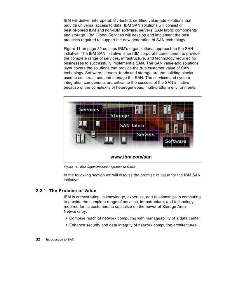
IBM will deliver interoperability-tested, certified value-add solutions thatprovide universal access to data. IBM SAN solutions will consist ofbest-of-breed IBM and non-IBM software, servers, SAN fabric componentsand storage. IBM Global Services will develop and implement the bestpractices required to support the new generation of SAN technology.
Figure 11 on page 32 outlines IBM’s organizational approach to the SANinitiative. The IBM SAN initiative is an IBM corporate commitment to providethe complete range of services, infrastructure, and technology required forbusinesses to successfully implement a SAN. The SAN value-add solutionslayer covers the solutions that provide the true customer value of SANtechnology. Software, servers, fabric and storage are the building blocksused to construct, use and manage the SAN. The services and systemintegration components are critical to the success of the SAN initiativebecause of the complexity of heterogeneous, multi-platform environments.
Figure 11. IBM Organizational Approach to SANs
In the following section we will discuss the promise of value for the IBM SANinitiative.
2.2.1 The Promise of ValueIBM is orchestrating its knowledge, expertise, and relationships in computingto provide the complete range of services, infrastructure, and technologyrequired for its customers to capitalize on the power of Storage AreaNetworks by:
• Combine reach of network computing with manageability of a data center
• Enhance security and data integrity of network computing architectures
www.ibm.com/san
32 Introduction to SAN

• Provide anywhere/anytime universal access to data regardless of theplatform, source, format, or application in which the data is archived
Figure 12 on page 33 illustrates the following concepts:
• The bottom layer is the hardware, both servers and storage devices, thatneed to be interconnected and enabled for SAN connectivity. IBM willsupport a phased implementation of FC technology through both tacticaland strategic moves. Tactically, IBM will deliver bridges (gateways) thatenable FC connectivity to current devices and systems. Strategically, IBMwill implement ESCON to FICON and SCSI/SSA to FC migrations.
Figure 12. Outline of IBM SAN Promise of Value
• The next layer, connectivity, is the physical storage network. IBM willprovide the necessary storage network hardware to build SANs. IBM willalso deliver frameworks and tools to build platform-independent networks.IBM will provide a flexible and scalable building block infrastructure forplug-and-play interoperability across different vendors and platforms.
• The third layer is management. IBM will port mature and provenmanagement technologies to the open systems world. Some of thesetechnologies are first generation (ESCON) SAN switch fabric managementand system managed storage concepts from OS/390 systems. IBM is alsoworking with Tivoli to develop a zero-latency, one-touch management
Extract the value of dataDisk & Tape PoolingOutboard data movementClustering, Data Sharing
Zero latency, one-touch managementCentralized focal pointReduced costFlexibility and automation
Migration pathsInvestment protectionFibre Channel (FICON/FCP)Distance, speed, reliabilityHubs, switchesAny storage to any system
SAN-enabledNative attachmentsSAN aware
SAN from initiative to implementationReduced time & cost to implementSkilled ResourcesSAN Integration, testing & verification
Connect
SAN Hardware BaseServers and Storage
Exploit
Manage
Serv
ices
and
Supp
ort
Solu
tions
The IBM SAN Initiative 33
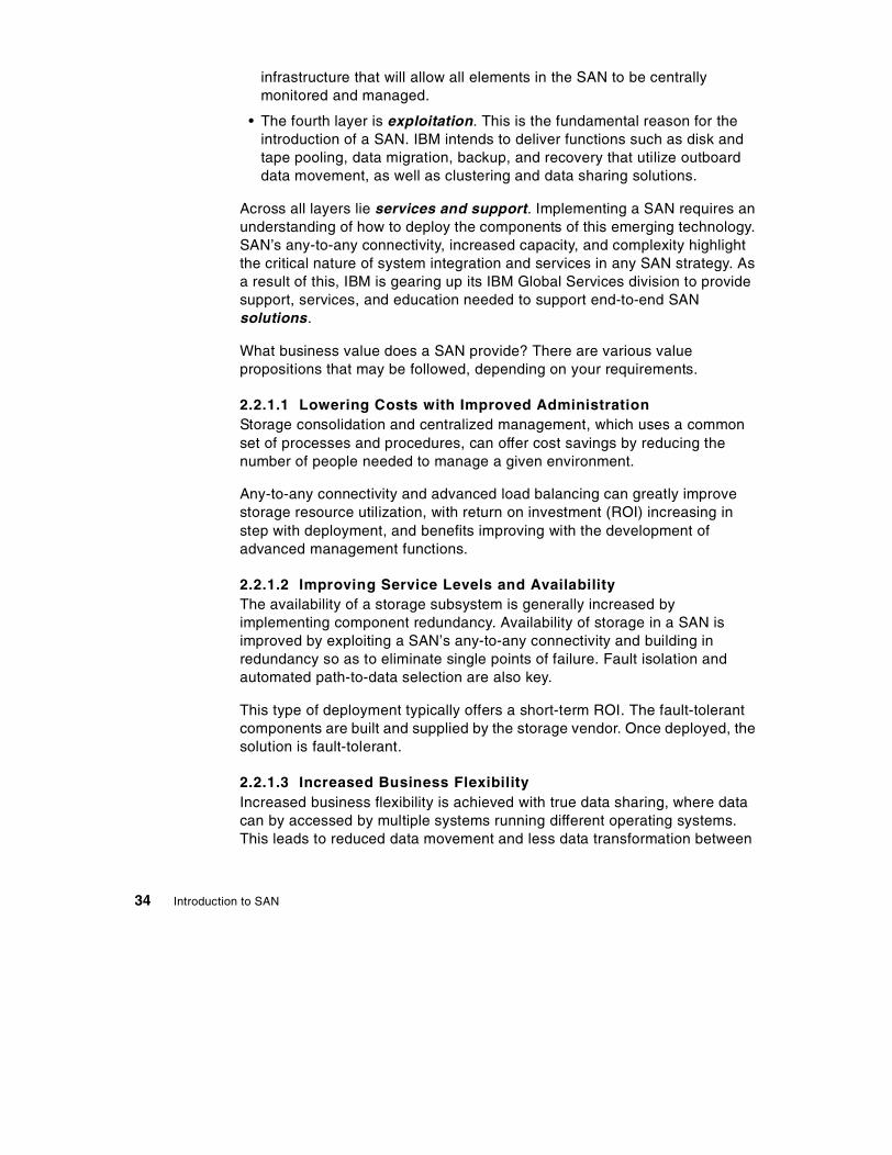
infrastructure that will allow all elements in the SAN to be centrallymonitored and managed.
• The fourth layer is exploitation. This is the fundamental reason for theintroduction of a SAN. IBM intends to deliver functions such as disk andtape pooling, data migration, backup, and recovery that utilize outboarddata movement, as well as clustering and data sharing solutions.
Across all layers lie services and support. Implementing a SAN requires anunderstanding of how to deploy the components of this emerging technology.SAN’s any-to-any connectivity, increased capacity, and complexity highlightthe critical nature of system integration and services in any SAN strategy. Asa result of this, IBM is gearing up its IBM Global Services division to providesupport, services, and education needed to support end-to-end SANsolutions.
What business value does a SAN provide? There are various valuepropositions that may be followed, depending on your requirements.
2.2.1.1 Lowering Costs with Improved AdministrationStorage consolidation and centralized management, which uses a commonset of processes and procedures, can offer cost savings by reducing thenumber of people needed to manage a given environment.
Any-to-any connectivity and advanced load balancing can greatly improvestorage resource utilization, with return on investment (ROI) increasing instep with deployment, and benefits improving with the development ofadvanced management functions.
2.2.1.2 Improving Service Levels and AvailabilityThe availability of a storage subsystem is generally increased byimplementing component redundancy. Availability of storage in a SAN isimproved by exploiting a SAN’s any-to-any connectivity and building inredundancy so as to eliminate single points of failure. Fault isolation andautomated path-to-data selection are also key.
This type of deployment typically offers a short-term ROI. The fault-tolerantcomponents are built and supplied by the storage vendor. Once deployed, thesolution is fault-tolerant.
2.2.1.3 Increased Business FlexibilityIncreased business flexibility is achieved with true data sharing, where datacan by accessed by multiple systems running different operating systems.This leads to reduced data movement and less data transformation between
34 Introduction to SAN

multiple formats. True data sharing supports today’s e-business environmentin which on-line or connected applications enable a business to seamlesslyexpand its reach to include its customers and suppliers. This valueproposition probably has the highest ROI, but is the most difficult to measure.
2.2.2 IBM Global ServicesThe deployment of a SAN solution in a multi-platform, heterogeneousenvironment can involve quite a large effort. IBM Global Services (IGS) hasthe global reach breadth of skills, and state-of-the-art comprehensive rangeof services to assist you in harnessing the power offered by SANs. IGS issetting up worldwide interoperability centers to enable customers to test andvalidate SAN solutions using both IBM and non-IBM components.
The SAN promise of any-to-any connectivity and the complexity it introduceshighlight the critical nature of both systems integration and services in anySAN strategy. IBM Global Services, in combination with service providerpartners, will offer the services and education required to plan and supportend-to-end SAN solutions.
For additional information, see the IBM SAN Web site at:
www.ibm.com/san
2.2.3 IBM and Industry Standards OrganizationsIBM participates in many industry standards organizations that work in thefield of SANs. IBM believes that industry standards must be defined and inplace for SANs to enter the IT business mainstream.
Probably the most important industry standards organization for SANs is theStorage Networking Industry Association (SNIA). IBM is a founding memberand board officer in SNIA. SNIA and other standards organizations and IBM’sparticipation are described in Chapter 7, “SAN StandardizationOrganizations” on page 97.
The IBM SAN Initiative 35

36 Introduction to SAN
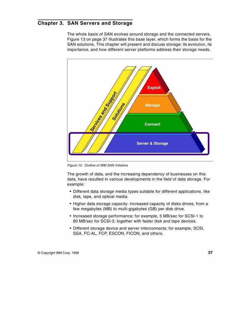
Chapter 3. SAN Servers and Storage
The whole basis of SAN evolves around storage and the connected servers.Figure 13 on page 37 illustrates this base layer, which forms the basis for theSAN solutions. This chapter will present and discuss storage: its evolution, itsimportance, and how different server platforms address their storage needs.
Figure 13. Outline of IBM SAN Initiative
The growth of data, and the increasing dependency of businesses on thisdata, have resulted in various developments in the field of data storage. Forexample:
• Different data storage media types suitable for different applications, likedisk, tape, and optical media.
• Higher data storage capacity: increased capacity of disks drives, from afew megabytes (MB) to multi-gigabytes (GB) per disk drive.
• Increased storage performance; for example, 5 MB/sec for SCSI-1 to80 MB/sec for SCSI-3, together with faster disk and tape devices.
• Different storage device and server interconnects; for example, SCSI,SSA, FC-AL, FCP, ESCON, FICON, and others.
Server & Storage
Connect
Manage
ExploitSe
rvic
esan
dSu
ppor
tSo
lutio
ns
© Copyright IBM Corp. 1999 37

• Data protection, using solutions like mirroring, remote copy, etc.
• Storage reliability, using various RAID implementations.
• Data and storage security and manageability.
Figure 14. Evolutions in Storage Architecture
Figure 14 on page 38 illustrates the evolution of storage architecture inrelation to era or phase of computing, from the centralized computing withcontroller-based dedicated storage, to the Client/Server model withdistributed data, and finally to the current networked era calling with itsrequirement for universal access to data, robust software tools, and datamanagement solutions.
3.1 Servers and Storage Environments
Figure 15 on page 39 illustrates the different islands of information or data asthey exist due to the different operating systems and hardware platforms.
1980-90s
1970-80s
New Era
intelligentcontroller
controller
storageserver
Netw orked ModelGlobal data accessBroader management
Client/Server ModelDistributed dataM anagement challenges
Dedicated ModelCentralized management
38 Introduction to SAN
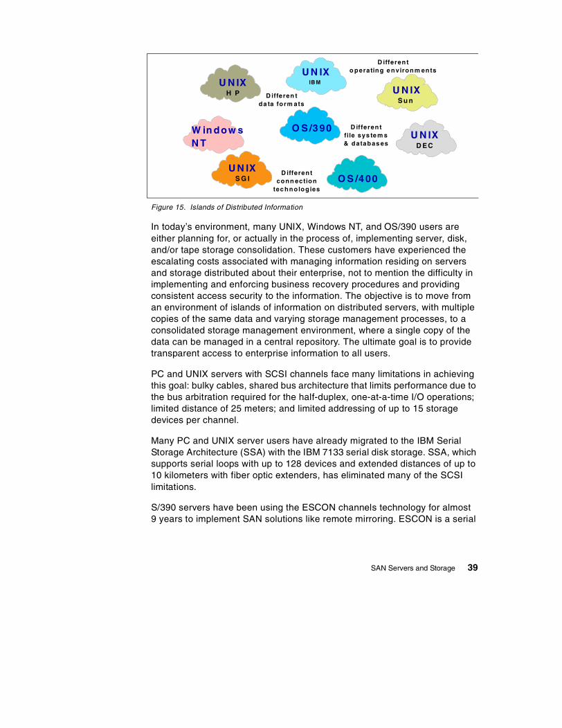
Figure 15. Islands of Distributed Information
In today’s environment, many UNIX, Windows NT, and OS/390 users areeither planning for, or actually in the process of, implementing server, disk,and/or tape storage consolidation. These customers have experienced theescalating costs associated with managing information residing on serversand storage distributed about their enterprise, not to mention the difficulty inimplementing and enforcing business recovery procedures and providingconsistent access security to the information. The objective is to move froman environment of islands of information on distributed servers, with multiplecopies of the same data and varying storage management processes, to aconsolidated storage management environment, where a single copy of thedata can be managed in a central repository. The ultimate goal is to providetransparent access to enterprise information to all users.
PC and UNIX servers with SCSI channels face many limitations in achievingthis goal: bulky cables, shared bus architecture that limits performance due tothe bus arbitration required for the half-duplex, one-at-a-time I/O operations;limited distance of 25 meters; and limited addressing of up to 15 storagedevices per channel.
Many PC and UNIX server users have already migrated to the IBM SerialStorage Architecture (SSA) with the IBM 7133 serial disk storage. SSA, whichsupports serial loops with up to 128 devices and extended distances of up to10 kilometers with fiber optic extenders, has eliminated many of the SCSIlimitations.
S/390 servers have been using the ESCON channels technology for almost9 years to implement SAN solutions like remote mirroring. ESCON is a serial
H P
D EC
Su n
U N IX
O S /3 90
O S /4 00
U N IX
U N IX
U N IX
W in dow sN T
U N IXS G I
D ifferen tda ta form ats
D ifferen to perating e nvironm ents
D ifferen tfile sys te m s& databas es
D ifferen tconn ection
tec hno log ies
IB M
SAN Servers and Storage 39

transfer, switched point-to-point Fibre Channel technology that replacedmainframe parallel channels.
S/390 FICON channels are a technology upgrade to the S/390 ESCONchannel, using industry standard Fibre Channel technology. FICON majorbenefits are higher performance and more extensive addressing. Since S/390FICON is an FC-4 protocol, it can share the same infrastructure with otherFibre Channel protocols, such as FCP.
Fibre Channel Arbitrated Loop FC-AL provides many benefits, includingsmaller cables and connectors, faster data transfers, and a wide range ofFibre Channel connection options, including point-to-point, loop, andswitched fabric. Distances are up to 10 kilometers, and loop addressingsupports up to 127 storage devices.
3.1.1 The ChallengeThe real challenge today is to implement a true heterogeneous storage anddata consolidation across different hardware and operating systemsplatforms; for example, disk and tape sharing across OS/390, UNIX, andWindows NT.
Figure 16 on page 40 illustrates the consolidation movement from thedistributed islands of information to a single heterogeneous configuration.
Figure 16. Disk and Tape Storage and Data Consolidation
Disk and Tape Storage Consolidation
OS/390 AIX
HP-UX
Islands of InformationDistributed servers and storageSeparate storage managementSeparate islands of information
Consolidated StorageConsolidated storage systemsConsolidated storage managementConsolidated enterprise data
Solaris
HP-UXWin NT
Solaris
AIX
Win NTWin NT
Win NT
OS/390
40 Introduction to SAN

IBM’s Seascape architecture addresses this movement from islands ofdistributed data to a single heterogeneous SAN. For more information onstorage consolidation, see IBM Storage Solutions for Server Consolidation,SG24-5355. Figure 17 on page 41 shows the underlying principles of the IBMstorage strategy. The Seascape architecture — with its concept of integratingleading technologies from IBM to provide storage solutions for all platforms,together with SAN, consolidation of servers, storage, applications, and data— is a part of that strategy.
Figure 17. IBM Storage Strategy
Storage consolidation is not a simple task. Each platform, along with itsoperating system, treats data differently at various levels in the systemarchitecture, thus creating many challenges:
• Different attachment protocols, such as SCSI, ESCON, and FICON.
• Different Data formats, such as Extended Count Key Data (ECKD), blocks,clusters, and sectors.
• Different file systems, such as Virtual Storage Access Method (VSAM),Journal File System (JFS), Andrew File System (AFS), and Windows NTFile System (NTFS).
PCservers
AS/400servers
UNIXservers
storage areanetwork
UNIXNT
Disk Storage
enterprise-widetape family
OS/390OS/400
UNIXNT
Tape Storage
Enterprise Data
Web-basedadministration
S/390servers
data manager
storage resource manager
enterprise-widedisk family
OS/390OS/400
SAN Servers and Storage 41
• OS/400, with the concept of single-level storage.
• Different file system structures, such as catalogs and directories.
• Different file naming conventions, such as AAA.BBB.CCC andDIR/Xxx/Yyy.
• Different data encoding techniques, such as EBCDIC, ASCII, floatingpoint, and little or big endian.
Figure 18 on page 42 is a brief summary of these differences and theassociated system architecture layers, excluding OS/400 for simplisticreasons.
Figure 18. Hardware and Operating Systems Differences
3.2 Server Environments
Each of the different server platforms — OS/390, UNIX (AIX, HP, SUN, andothers), OS/400, and Windows NT (PC Servers) — have implementedSAN-like solutions using various interconnects and storage technologies. Thesections below explore these solutions and the different implementations oneach of the platforms.
3.2.1 S/390 ServersThe System/390 (S/390) is a processor(s) and Operating System set.Historically, S/390 servers have supported many different operating systems,
Platform DifferencesPlatform
DataEncoding
File SystemsStructuresNaming
Formats
AttachmentProtocols
OS/390
EBCDICIEEE Floating PointRight Justified
VSAM...VTOCs - CatalogsAAA.BBB.CCC
ECKD
ESCON / OEMI
UNIX
ASCIIDbl. Precision F.F.Right Justified
JFS...DirectoriesDIR/Xxx/Yyy
Clusters / Sectors
SCSI...
Win/NT
ASCIIDbl. Precision F.F.Left Justified
FAT...DirectoriesDIR\Xxx\Yyy
Clustors / Sectors
SCSI...
Ap
plic
atio
n/
Mid
dlew
are
Dat
abas
eM
anag
erS
tora
ge
Su
bsy
stem
System Layers
Note: UNIX file systems differ between vendor implementations
Differences determined/resolved atapplication/DB manager layer
(c) Copyright IBM Corporation 1998
42 Introduction to SAN
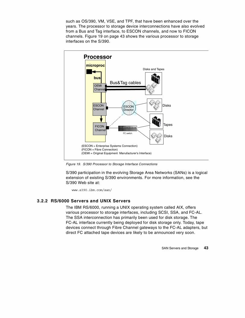
such as OS/390, VM, VSE, and TPF, that have been enhanced over theyears. The processor to storage device interconnections have also evolvedfrom a Bus and Tag interface, to ESCON channels, and now to FICONchannels. Figure 19 on page 43 shows the various processor to storageinterfaces on the S/390.
Figure 19. S/390 Processor to Storage Interface Connections
S/390 participation in the evolving Storage Area Networks (SANs) is a logicalextension of existing S/390 environments. For more information, see theS/390 Web site at:
www.s390.ibm.com/san/
3.2.2 RS/6000 Servers and UNIX ServersThe IBM RS/6000, running a UNIX operating system called AIX, offersvarious processor to storage interfaces, including SCSI, SSA, and FC-AL.The SSA interconnection has primarily been used for disk storage. TheFC-AL interface currently being deployed for disk storage only. Today, tapedevices connect through Fibre Channel gateways to the FC-AL adapters, butdirect FC attached tape devices are likely to be announced very soon.
Tapes
microproc
bus
OEMIChannel
ESCONChannel
Bus&Tag cables
ESCONDirector
Processor
(ESCON = Enterprise Systems Connection)(FICON = Fibre Connection)(OEMI = Original Equipment Manufacturer's Interface)
FICONChannel
Disks and Tapes
Disks
DisksFC switch
SAN Servers and Storage 43

Figure 20 on page 44 shows the various processor to storage interconnectoptions for the RS/6000 family.
Figure 20. RS6000 Processor to Storage Interconnections
The various UNIX system vendors in the market deploy different variants ofthe UNIX operating system, each having some unique enhancements andoften supporting different file systems, such as the Journal File System (JFS)and the Andrew File System (AFS). The server to storage interconnect issimilar to RS/6000, as shown in Figure 20 on page 44.
RS/6000 is committed to delivering world-class SAN solutions based on FibreChannel so that our customers can have the type of information access andmanageability that doing business in the next century will require. For moreinformation, see the RS/6000 Web site at:
www.rs6000.ibm.com/hardware/san
3.2.3 AS/400 ServersThe AS/400 system architecture is defined by a high-level machine interface,referred to as Technology Independent Machine Interface (TIMI), that isolatesapplications (and much of the operating system) from the actual underlyingsystems hardware.
Processormicroproc
bus
SSA /FCAdapter
SCSIAdapter
SCSI bus
FCAdapter
loop
Disk & Tape Drives
Disk Drives
FC Switch/ hub
44 Introduction to SAN

The main processor and the I/O processors are linked using a system bus,including Systems Product Division (SPD) and also Peripheral ComponentInterconnect (PCI). Additionally, the AS/400 implements I/O processors thatare architected for end user technologies, including Windows NT and Novell.Figure 21 on page 45 summarizes the various modules of an AS/400hardware architecture.
Figure 21. AS400 Hardware Design
Several architectural features of the AS/400 distinguish this system fromother machines in the industry. These features include:
• Technology Independent Machine Interface
• Object-based systems design
• Single-level storage
• Integration of application programs into the operating system
3.2.3.1 Single Level StorageSingle-level storage is probably the most significant differentiator in a SANsolution implementation on AS/400, as compared to other systems likeOS/390, UNIX, and Windows NT. In OS/400, both the main storage (memory)and the secondary storage (disks) are treated as a very large virtual addressspace known as Single Level Storage (SLS).
BUS
DASDTAPE
COMMW/S
I/OProcessor
RAIDWireless
EthernetFax
SpecialFunction
OP's
NTNovell
ApplicationServers
MainProcessor
Memory
ServiceProcessor
SAN Servers and Storage 45

Figure 22 on page 46 compares the OS/400 SLS addressing with the wayWindows NT or UNIX systems work, using the processor local storage. With32-bit addressing, each process (job) has 4 GB of addressable memory. With64-bit of SLS addressing, over 18 million Terabytes (18 Exabytes) ofaddressable storage is possible. Because a single page table maps all virtualaddresses to physical addresses, task switching is very efficient. SLS furthereliminates the need for address translation, thus speeding up data access.
Figure 22. OS/400 versus NT or UNIX Storage Addressing
AS/400 intends to support SAN based storage solutions in the future. Thesesolutions will initially involve Fibre Channel technology, hubs, external IBMstorage subsystems, and high performance tape drives.
For more information, see the AS/400 Web site at:
www.as400.ibm.com/periph/san.htm
3.2.4 Windows NT and Netfinity ServersBased on the reports of various analysts regarding growth in the Windows NTserver market — both in number and size of Windows NT servers —Windows NT will become the largest market for SAN solution deployment.More and more Windows NT servers will host mission-critical applicationsthat will benefit from SAN solutions such as disk and tape pooling, tapesharing, and remote copy.
The processor to storage interfaces on Netfinity servers (IBM’s INTEL-basedprocessors that support the Microsoft Windows NT Operating System) arequite similar to those supported on UNIX servers, like SCSI, SSA, and FC-AL.Figure 23 on page 47 illustrates the various processor to storageinterconnects.
18,000,000 TB
OS/400 NT or UNIX
job1
4GB
job3
4GB
job2
4GBjob 1
job 2
job 3
46 Introduction to SAN
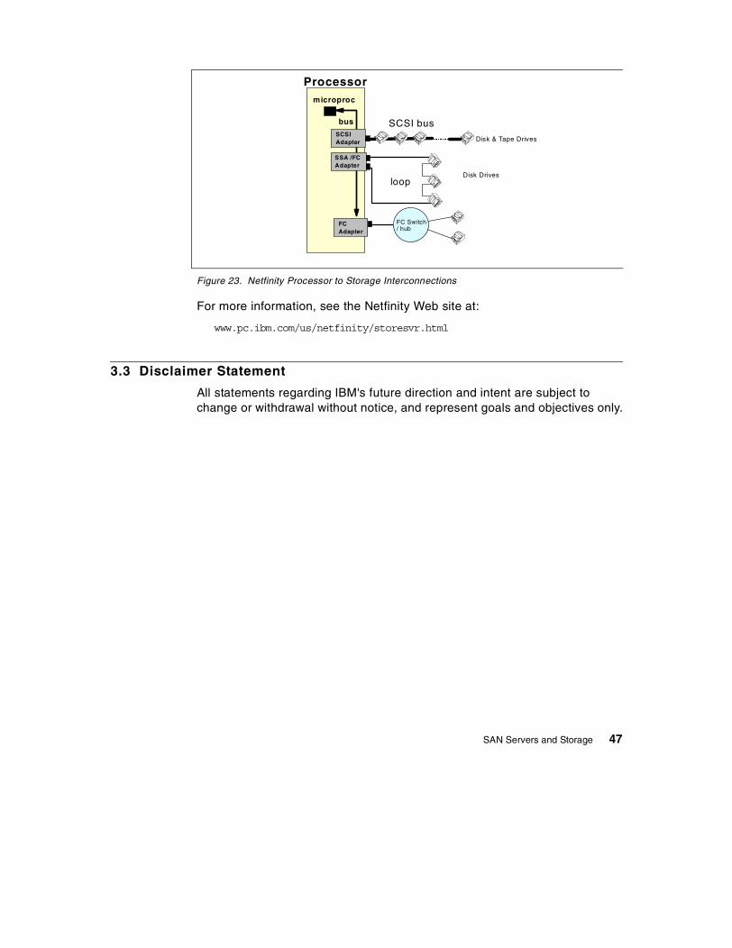
Figure 23. Netfinity Processor to Storage Interconnections
For more information, see the Netfinity Web site at:
www.pc.ibm.com/us/netfinity/storesvr.html
3.3 Disclaimer Statement
All statements regarding IBM's future direction and intent are subject tochange or withdrawal without notice, and represent goals and objectives only.
Processormicroproc
bus
SSA /FCAdapter
SCSIAdapter
SCSI bus
FCAdapter
loop
Disk & Tape Drives
Disk Drives
FC Switch/ hub
SAN Servers and Storage 47

48 Introduction to SAN

Chapter 4. SAN Fabrics and Connectivity
4.1 Fabric
A Fibre Channel SAN employs a fabric to connect devices. A fabric can be assimple as a single cable connecting two devices. However, the term is mostoften used to describe a more complex network utilizing hubs, switches andgateways.
Figure 24. Outline of IBM SAN Initiative
4.2 Storage Area Network Environment
Historically, interfaces to storage consisted of parallel bus architectures (suchas SCSI and IBM’s Bus and Tag) that supported a small number of devices.Fibre Channel technology provides a means to implement robust storagearea networks that may consist of hundreds or thousands of devices. FibreChannel Storage Area Networks support high bandwidth storage traffic on theorder of 100 MB/sec, and enhancements to the Fibre Channel standard willsupport even higher bandwidth in the near future.
Storage subsystems, storage devices, and server systems can be attached toa Fibre Channel Storage Area Network. Depending on the implementation,several different components can be used to build a Storage Area Network.
Server & Storage
Connect
Manage
ExploitSe
rvic
esan
dSu
ppor
tSo
lutio
ns
© Copyright IBM Corp. 1999 49

A Fibre Channel network may be composed of many different types ofinterconnect entities, including switches, hubs, and bridges.
Different types of interconnect entities allow Fibre Channel networks ofvarying scale to be built. In smaller SAN environments, Fibre Channelarbitrated loop topologies employ hub and bridge products. As SANsincrease in size and complexity, Fibre Channel switches can be introduced tofacilitate a more flexible and fault tolerant configuration. Each of thecomponents that compose a Fibre Channel SAN should provide an individualmanagement capability, as well as participate in an often complex end-to-endmanagement environment.
4.2.1 Server-Attached Storage (SAS)Server-attached or bus-attached storage operates through the server. Earlyon, central host mainframe processors could access a variety of storagedevices through channels. The central processor managed the processingload, while the I/O processor, also within the mainframe, sent and receiveddata to and from storage devices asynchronously. This was the first stage ofintroducing intelligence into the data transfer process. Server-attachedstorage architectures dominated the scene for several years, from mainframeprocessor channels to PC server bus slots and adapters. See Figure 25 onpage 50.
Figure 25. Server-Attached Storage (SAS)
Server-Centric
Channel Attach
MainframePersonal Computer
Server-Attached Storage(SAS)
SCSIAttach
50 Introduction to SAN

4.2.2 Network-Attached Storage (NAS)Local Area Networks came along next, and helped in the sharing of data filesamong groups of desktop microcomputers. Soon it became clear that LANswould be a significant step toward distributed, client/server systems.Large-scale client/server systems were then constructed, tying sizablenumbers of LANs together through Wide Area Networks (WANs). The ideawas to leverage cheap microcomputers and cheap disk storage to replaceexpensive (but reliable) central computers. See Figure 26 on page 51.
NAS describes technology in which an integrated storage system, such as adisk array or tape device, connects directly to a messaging network through aLAN interface, such as Ethernet, using messaging communications protocolslike TCP/IP. The storage system functions as a server in a client/serverrelationship. It has a processor and an operating system or micro-kernel, andit processes file I/O protocols such as Network File System (NFS) to managethe transfer of data between itself and its clients.
An example of network-attached storage is the IBM 3466 Network StorageManager (NSM). For more information on NSM, see the Web site:
www.storage.ibm.com/nsm/nsmhome.htm
Figure 26. Network Attached Storage (NAS)
Local Area Network (Messaging Protocol- TCP/IP, NET BIOS)
Network-Attached Storage(NAS)
WebServer
ApplicationServer
DatabaseServer
SAN Fabrics and Connectivity 51

4.2.3 Storage Area Network (SAN)A SAN is a dedicated high performance network to move data betweenheterogeneous servers and storage resources. Unlike Network AttachedStorage (NAS), a separate dedicated network is provided which avoids anytraffic conflicts between clients and servers on the traditional messagingnetwork. See Figure 27 on page 52.
A Fibre Channel based SAN combines the high performance of an I/Ochannel and the advantages of a network (connectivity and distance of anetwork) using similar network technology components like routers, switchesand gateways.
Unlike NAS products, SAN products do not function like a server. Instead, theSAN product processes block I/O protocols, such as FCP (SCSI) or FICON,for some other system, quite possibly a server.
Figure 27. Storage Area Network (SAN)
4.3 Fibre Channel
Fibre Channel based networks share many similarities with other networks,but differ considerably by the absence of topology dependencies. Networksbased on Token Ring, Ethernet, and FDDI are topology dependent andcannot share the same media because they have different rules forcommunication. The only way they can interoperate is through bridges androuters. Each uses its own media dependent data encoding methods andclock speeds, header format and frame length restrictions. Fibre Channel
Fibre ChannelSw itch
Local Area Netw o rk (M essaging Protocol- TCP/IP , NET BIO S)
S torage Area Netw ork(Data Proto col - FCP, FICO N, etc .)
D ISK
DISKD ISKDISKTAPE TAPE
DISKFibre C hannel
Sw itch
Router
52 Introduction to SAN

based networks support three types of topologies, which includepoint-to-point, loop (arbitrated), and star (switched). These can bestand-alone or interconnected to form a fabric.
4.3.1 Point-to-PointPoint-to-point is the easiest Fibre Channel configuration to implement, and itis also the easiest to administer. This simple link can be used to provide ahigh-speed interconnect between two nodes, as shown in Figure 28 on page53.
Figure 28. Fibre Channel Point-to-Point Topology
Possible implementations of point-to-point connectivity may include thefollowing connections:
• Between central processing units
• From a workstation to a specialized graphics processor or simulationaccelerator
• From a file server to a disk array or optical jukebox
When greater connectivity and performance is required, each device can beconnected to a fabric without incurring any additional expense beyond thecost of the fabric itself.
4.3.2 Loops and Hubs for ConnectivityThe Fibre Channel arbitrated loop offers relatively high bandwidth andconnectivity at a low cost. For a node to transfer data, it must first arbitrate towin control of the loop. Once the node has control, it is now free to establish apoint-to-point (virtual) connection with another node on the loop. After this
Server
Full Duplex200 MB/s (100x2)
100 M B/s
100 MB /s
Disk
SAN Fabrics and Connectivity 53

5
point-to-point (virtual) connection is established, the two nodes consume allof the loop’s bandwidth until the data transfer operation is complete. Once thetransfer is complete, any node on the loop can now arbitrate to win control ofthe loop. The characteristics which make Fibre Channel arbitrated loop sopopular include:
• Support of up to 126 devices is possible on a single loop.
• Devices can be hot swapped with the implementation of hubs and bypassports.
• A loop is self-discovering (it finds out who is on the loop and tells everyoneelse).
• Logic in the port allows a failed node to be isolated from the loop withoutinterfering with other data transfers.
• Virtual point-to-point communications are possible.
• A loop can be interconnected to other loops to essentially form its ownfabric.
• A loop can be connected to a Fibre Channel switch to create fanout, or theability to increase the size of the fabric even more.
More advanced FC hub devices support FC loop connections while offeringsome of the benefits of switches. Figure 29 on page 54 shows an FC loopusing a hub.
Figure 29. Fibre Channel Loop Topology
Fibre C hannelArb itrated Loop
(FC -AL)
H U B
4 Introduction to SAN

4.3.3 Switches for Scalability, Performance and AvailabilityFibre Channel switches function in a manner similar to traditional networkswitches to provide increased bandwidth, scalable performance, increasednumber of devices, and in some cases, increased redundancy. Fibre Channelswitches vary in the number of ports and media types they support. Multipleswitches can be connected to form a switch fabric capable of supporting alarge number of system hosts and storage subsystems as shown in Figure 30on page 55. When switches are connected, each switch’s configurationinformation has to be copied (cascaded) into all other participating switches.
Figure 30. Fibre Channel Switched Topology
4.3.4 Switched Fabric without CascadingSwitched point-to-point (without cascading) can support configurationsrequired by very large systems (IBM’s ESCON directors, for example). Theconfiguration can be set up to allow every system to have access to everyswitch, and every controller to be connected to at least two switches. Thisallows any system to get to any controller/device, and it allows for continuousoperation (with degraded performance) in the event that a switch fails. Anexample of a fabric with non-cascaded switches is shown in Figure 31 onpage 56.
Fibre ChannelSwitch
Fibre ChannelSwitch
SAN Fabrics and Connectivity 55

Figure 31. Fibre Channel Switched Topology (Non-Cascaded Switches)
4.3.5 Switched Fabric with CascadingA switched fabric with cascading provides for interconnections betweenswitches, where the collection of switches looks like one large, any-to-anyswitch. Management becomes more extensive than basic switchedpoint-to-point configurations. Inter-switch links can fail and must be identified(many switch vendors do not yet support any reporting on inter-switch links).Traffic can be routed in many ways. For technical, security, or other reasons,various levels of zoning (specifying access authority to connected ports ordevices) or other mechanisms may be used to restrict the any-to-any access.Performance monitoring and configuration changes (upgrades) needed tokeep the network performing adequately are more complex. The primaryadvantage of a switched cascaded fabric is that it looks like a very largelogical switch, where a single connection provides access to any other porton the total set of switches, as shown in Figure 32 on page 57.
Fibre ChannelSwitch
Fibre ChannelSwitch
56 Introduction to SAN
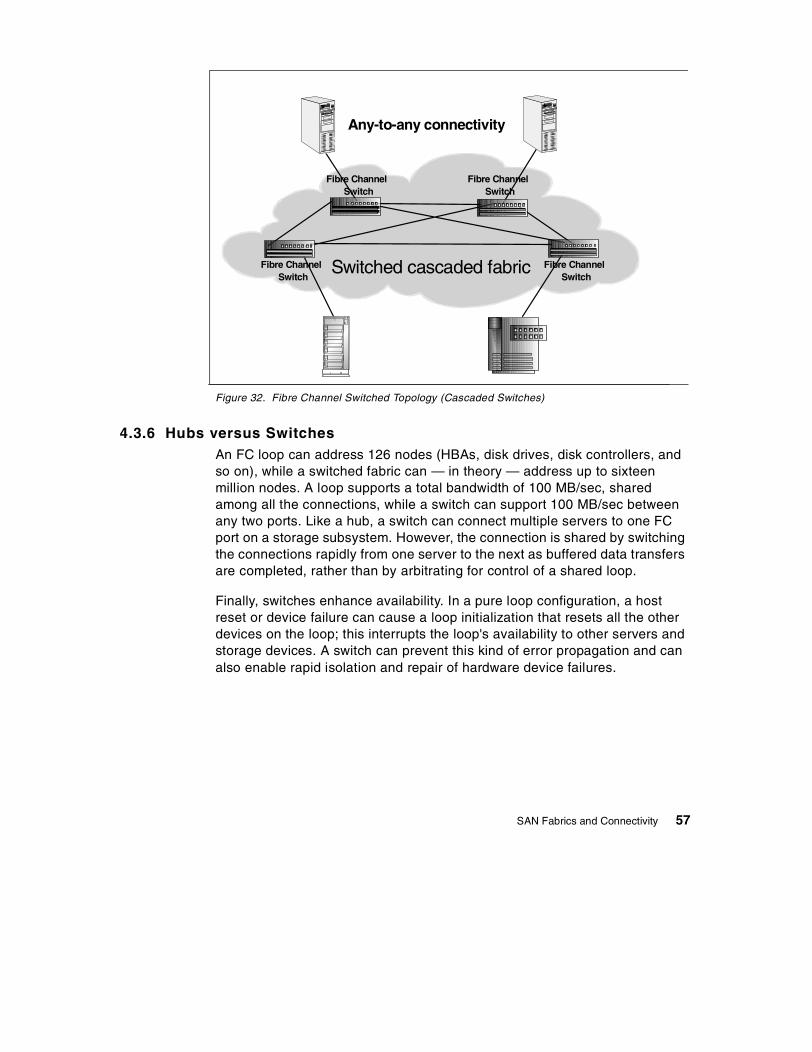
Figure 32. Fibre Channel Switched Topology (Cascaded Switches)
4.3.6 Hubs versus SwitchesAn FC loop can address 126 nodes (HBAs, disk drives, disk controllers, andso on), while a switched fabric can — in theory — address up to sixteenmillion nodes. A loop supports a total bandwidth of 100 MB/sec, sharedamong all the connections, while a switch can support 100 MB/sec betweenany two ports. Like a hub, a switch can connect multiple servers to one FCport on a storage subsystem. However, the connection is shared by switchingthe connections rapidly from one server to the next as buffered data transfersare completed, rather than by arbitrating for control of a shared loop.
Finally, switches enhance availability. In a pure loop configuration, a hostreset or device failure can cause a loop initialization that resets all the otherdevices on the loop; this interrupts the loop's availability to other servers andstorage devices. A switch can prevent this kind of error propagation and canalso enable rapid isolation and repair of hardware device failures.
Switched cascaded fabric
Any-to-any connectivity
Fibre ChannelSwitch
Fibre ChannelSwitch
Fibre ChannelSwitch
Fibre ChannelSwitch
SAN Fabrics and Connectivity 57

4.3.7 Mixed Switch and Loop TopologiesTo mix Fibre Channel Arbitrated Loop with Fibre Channel switches, the switchmust have a specific Fiber Loop (FL) port to attach to the loop. Discoverybecomes more complex, and management software must be able to deal withthe combination of hubs and switches in the configuration, for example, forthe configuration shown in Figure 33 on page 58.
Figure 33. Switch Attached Arbitrated Loop
Fibre Channel’s Media Access Rules (MAR) enable systems to self-configurethemselves to achieve maximum performance (even in a mixed media,copper, and optical fiber environment). A Fibre Channel port only has tomanage the simple point-to-point connection between itself and the fabric.Whether the Fibre Channel topology consists of a point-to-point, arbitratedloop or switch is irrelevant because the station management issues related totopology are not part of the Fibre Channel ports, but the responsibility of thefabric. Because Fibre Channel delegates the responsibility for stationmanagement to the fabric and employs consistent data encoding and mediaaccess rules, topology independence is achieved. It also means that FibreChannel ports are much less complex than typical network interfaces, and asa result, less costly.
Fibre ChannelArbitrated Loop
(FCAL)
SwitchedFabric
ArbitratedLoop
Fibre ChannelSwitch
Fibre ChannelSwitch
HUB
58 Introduction to SAN

4.3.8 ESCON DirectorsUsing switched technology, ESCON Directors provided the first truehomogeneous switched Storage Area Network. ESCON Directors provide acompletely separate network dedicated to move data. Data can betransferred at a rate of 17 MB/sec, and dynamic connections can beestablished between attached ESCON control units and channels. See Figure34 on page 59.
Figure 34. ESCON Storage Area Network
4.3.9 FICON DirectorsFICON Directors are standard Fibre Channels switches with additionalfunction to provide management from OS/390. They provide dynamicconnections between FICON channels and control units with FICONinterfaces, as shown in Figure 35 on page 60.
Since the FICON Director is a standard Fibre Channel switch, non-S/390servers and storage systems can also be attached.
TAPE
VM/ESA
LAN
ESCONDIRECTOR
SAN
DISK
LAN
OS/390MVS/ESA
LAN
TAPE
DISK
ESCONDIRECTOR
SAN Fabrics and Connectivity 59
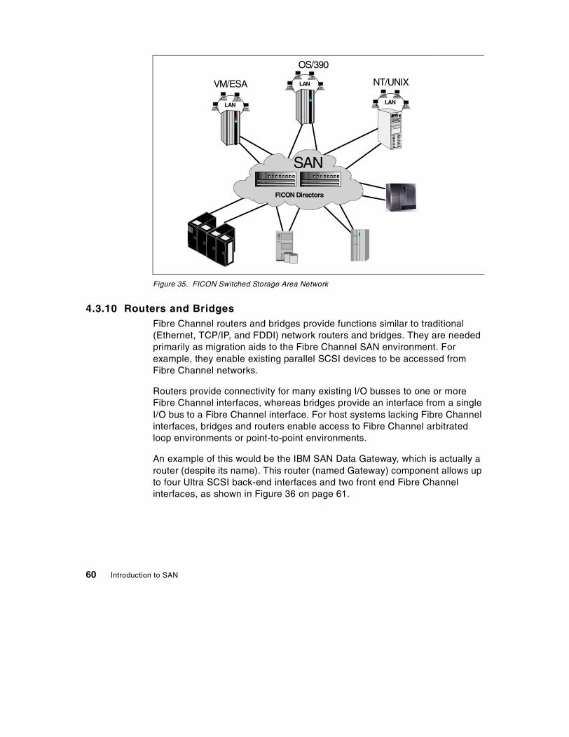
Figure 35. FICON Switched Storage Area Network
4.3.10 Routers and BridgesFibre Channel routers and bridges provide functions similar to traditional(Ethernet, TCP/IP, and FDDI) network routers and bridges. They are neededprimarily as migration aids to the Fibre Channel SAN environment. Forexample, they enable existing parallel SCSI devices to be accessed fromFibre Channel networks.
Routers provide connectivity for many existing I/O busses to one or moreFibre Channel interfaces, whereas bridges provide an interface from a singleI/O bus to a Fibre Channel interface. For host systems lacking Fibre Channelinterfaces, bridges and routers enable access to Fibre Channel arbitratedloop environments or point-to-point environments.
An example of this would be the IBM SAN Data Gateway, which is actually arouter (despite its name). This router (named Gateway) component allows upto four Ultra SCSI back-end interfaces and two front end Fibre Channelinterfaces, as shown in Figure 36 on page 61.
FICON Directors
SAN
LAN
OS/390
LAN
NT/UNIX
LAN
VM/ESA
60 Introduction to SAN

Figure 36. IBM SAN Data Gateway
4.3.11 GatewaysIn the SAN environment a gateway component can, for example, connect twodifferent remote SANs with each other over a Wide Area Network, as shownin Figure 37 on page 61. A typical application requiring gateways would beremote copy solutions.
Figure 37. SAN Gateway Connecting Remote SANs
Fibre ChannelArbitrated Loop
Fibre ChannelArbitrated Loop
FC hostadapter
UNIXor
WindowsNT
Server
SA
ND
ata
Gat
eway
Magstar
FC hostadapter
UNIXor
WindowsNT
Server
IBM SAN Data Gateway
Ultra SCSI
SAN SAN
LAN
NT/UNIXLAN
OS/390
LAN
NT/UNIXLAN
VM/ESALAN
OS/390
LAN
VM/ESA
Wide area network
SAN Fabrics and Connectivity 61

62 Introduction to SAN
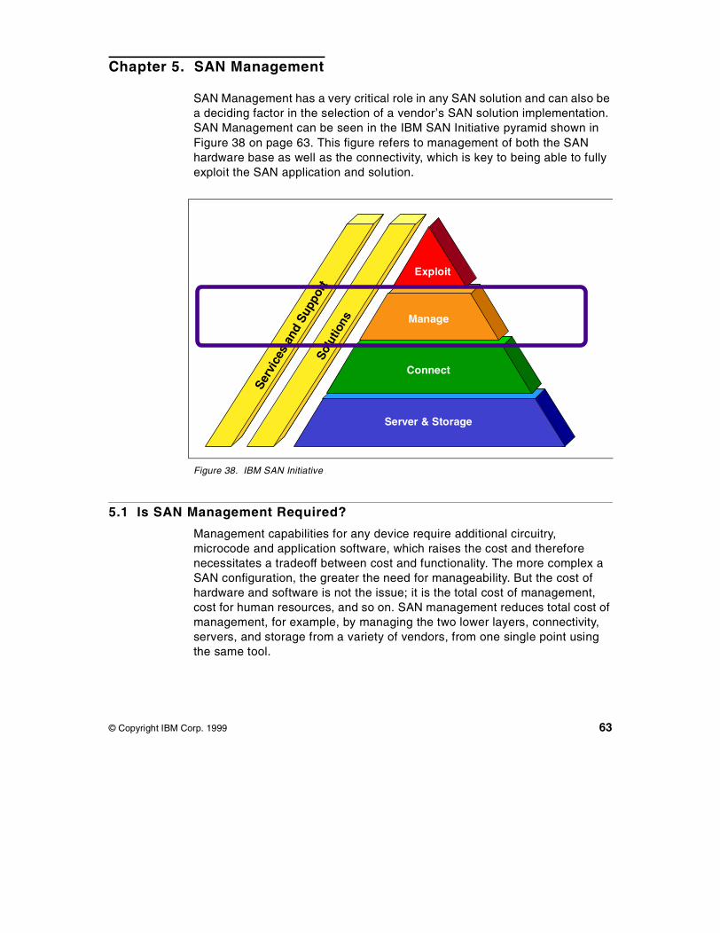
Chapter 5. SAN Management
SAN Management has a very critical role in any SAN solution and can also bea deciding factor in the selection of a vendor’s SAN solution implementation.SAN Management can be seen in the IBM SAN Initiative pyramid shown inFigure 38 on page 63. This figure refers to management of both the SANhardware base as well as the connectivity, which is key to being able to fullyexploit the SAN application and solution.
Figure 38. IBM SAN Initiative
5.1 Is SAN Management Required?
Management capabilities for any device require additional circuitry,microcode and application software, which raises the cost and thereforenecessitates a tradeoff between cost and functionality. The more complex aSAN configuration, the greater the need for manageability. But the cost ofhardware and software is not the issue; it is the total cost of management,cost for human resources, and so on. SAN management reduces total cost ofmanagement, for example, by managing the two lower layers, connectivity,servers, and storage from a variety of vendors, from one single point usingthe same tool.
Server & Storage
Connect
Manage
ExploitSe
rvic
esan
dSu
ppor
tSo
lutio
ns
© Copyright IBM Corp. 1999 63

For example, a large, 10-to-50 node arbitrated loop may have Host BusAdaptors (HBAs) and storage arrays from a variety of vendors. The storagenetwork may be running a server cluster application. The cablinginfrastructure may include a mix of copper as well as multi-mode andsingle-mode fiber. The loop topology may be transporting IP and SCSI-3(FCP) protocols. All these factors add complexity to the SAN, and makemanagement an essential part of a SAN vendor selection.
One of the biggest challenges facing SAN vendors is to create and agreeupon a common standard for SAN management that enables the ultimategoal of an any-to-any, centrally managed, heterogeneous SAN environment.
5.2 SAN Management Evolving Standards and Definitions
SAN Management architecture can be divided into three distinct levels —SAN storage level, SAN network level, and enterprise systems level. Figure39 on page 64 illustrates the three management levels in a SAN solution.
Figure 39. SAN Management Levels
HBAs
WANs & LANs
Storage Area NetworkHUBS
SWITCHES
GATEWAYS
HBAs
HBAs
En
terp
rise
Sys
tem
Lev
el
SA
NN
etw
ork
Leve
l
SA
NS
tora
ge
Lev
el
64 Introduction to SAN
5.2.1 SAN Storage LevelThe SAN storage level is composed of various storage devices such as disks,disk arrays, tapes and tape libraries. As configuration of a storage resourcemust be integrated with configuration of the server’s logical view of them, theSAN storage level management spans both storage resources and servers inFigure 38 on page 63.
Today, SAN storage predominantly uses the Small Computer SystemsInterface (SCSI) protocol. The ANSI SCSI-3 serial protocol is used over theFibre Channel by many SAN vendors in order to offer higher speeds, longerdistances, and greater device population for SANs, with few changes in theupper level protocols. The ANSI SCSI-3 serial protocol has also defined anew set of commands called SCSI Enclosure Services (SES) for basic devicestatus from storage enclosures.
5.2.1.1 SCSI Enclosure Services (SES)In SCSI legacy systems, SCSI protocol runs over a limited length parallelcable, with up to 15 devices in a chain. The latest version of SCSI-3 serialprotocol offers this same disk read/write command set in a serial format,which allows for the use of Fibre Channel, as a more flexible replacement ofparallel SCSI.
The ANSI SES proposal defines basic device status from storage enclosures.For example, DIAGNOSTICS and RECEIVE DIAGNOSTIC RESULTS commands can beused to retrieve power supply status, temperature, fan speed, and otherparameters from the SCSI devices.
SES has an impact on Fibre Channel - Arbitrated Loop (FC-AL) management,since it is a potential source of overhead with loop data traffic. For example, ifan FC-AL hub or switch supports SES queries, it becomes a participatingnode in the loop, and the management traffic generated on the loop wouldthen effectively reduce the server to storage data transfer throughput. MostSAN vendors deploy SAN management strategies using Simple NetworkManagement Protocol (SNMP) based and non-SNMP based (SES) protocols.
5.2.2 SAN Network LevelThe SAN network level is composed of all the various components thatprovide connectivity, like the SAN cables, SAN hubs, SAN switches,inter-switch links, SAN gateways, and Host Bus Adapters (HBAs).
This SAN network infrastructure becomes closely tied to the inter-networkinginfrastructure, as seen in Local Area Network (LAN) and Wide Area Networksolutions (WAN) solutions. The hubs, switches, gateways, and cabling, used
SAN Management 65
in LAN/WAN solutions, use the SNMP support feature to providemanagement of all these networking components. Most SAN solution vendorsalso mandate SNMP support for all the SAN networking components, which isthen used and exploited by SNMP based network management applicationsto report on the various disciplines of SAN management.
5.2.2.1 Simple Network Management Protocol (SNMP)SNMP, an IP-based protocol, has a set of commands for getting the statusand setting the operational parameters of target devices. The SNMPmanagement platform is called the SNMP manager, and the manageddevices have the SNMP agent loaded. Management data is organized in ahierarchical data structure called the Management Information Base (MIB).These MIBs are defined and sanctioned by various industry associations. Theobjective is for all vendors to create products in compliance with these MIBsso that inter-vendor interoperability can be achieved. If a vendor wishes toinclude additional device information that is not specified in a standard MIB,then that is usually done through MIB extensions.
The Storage Networking Industry Association (SNIA) very recentlyannounced formation of a task force to define standard MIBs for the SANindustry using the Fibre Channel interface that will enable SAN managementapplications to query the SAN fabric components (like switches) to obtaingeneral status information using Fabric Element (FE) MIBs and FibreChannel InterConnect (FC-IC) MIBs on supporting devices.
Figure 40 on page 67 illustrates the various elements of an SNMP-basedmanagement architecture.
66 Introduction to SAN

Figure 40. Elements of SNMP-Based Management Architecture
5.2.3 Enterprise Systems LevelThe enterprise systems level essentially ensures the ability to have a singlemanagement view and console.
Enterprise systems management applications have to integrate themanagement data and then present it in an easy-to-understand format. Thismanagement data comes from various layers of the enterprise infrastructure,including storage, networks, servers, and desktops, often with each of themrunning its own management application. In addition, the rapid deployment ofInternet-based solutions in the enterprise has necessitated Web-basedmanagement tools. Various industry-wide initiatives, like Web BasedEnterprise Management (WBEM), Common Interface Model (CIM), DesktopManagement Interface (DMI), and Java Management ApplicationProgramming Interface (JMAPI) are being defined and deployed today inorder to create some level of management standardization, and many SANsolutions vendors are deploying these standards in their products.
In heterogeneous management solutions, CIM enables data integration ofmanagement applications and WBEM provides Web access to the managedelements and managed data.
F A U LTC O N F IG U R AT IO NP E R F O R M A N C E
M IB
S N M P
N E T W O R K D E V IC EP h y s ic a l m a n a g e d o b je c t
S e r v ic e la y e r & p r o to c o ls
M a n a g e d r e s o u r s e d e f in a t io n
M a n a g e m e n t a p p lic a t io n s
SAN Management 67

5.2.3.1 Web Based Enterprise Management (WBEM)WBEM enables the industry to deliver a well-integrated set ofstandards-based management tools that leverage the emerging Webtechnologies and unify management interfaces.
5.2.3.2 Common Interface Model (CIM)CIM enables distributed management of systems and networks. It facilitates acommon understanding of management data across different managementsystems, and also facilitates the integration of management information fromdifferent sources.
5.3 SAN Management Strategy and Disciplines
There are many aspects to total SAN Management. Some of the simplerfunctions include:
• Device installation, configuration and monitoring• Inventory of resources on the SAN• Reporting utilities• Assistance in SAN planning
Some of the more advanced, highly valued functions include:
• Automated component and fabric topology discovery
• Management of the fabric configuration, including zoning configurations
• Name services
• Security management
• Health and performance monitoring
• Workload management/balancing of SAN activities based on applicationpriorities set by business objectives (for example, backup copy creationhas a lower priority than business transactions)
5.3.1 SAN Management StrategyA comprehensive SAN Management strategy covers the following generaltopics:
• Device management• Problem detection• Problem isolation• Problem diagnosis• Problem recovery• Predictive analysis
68 Introduction to SAN

Unlike many other management products available today, IBM offers acomprehensive SAN management solution family of products, calledStorWatch. The StorWatch products are based on the IBM Enterprise StorageResource Management (ESRM) disciplines. Figure 41 on page 69 illustratesIBM’s ESRM strategy.
Figure 41. IBM ESRM Strategy
ESRM strategy defines the various disciplines of storage management, suchas asset management, capacity management, configuration management,performance management, and availability management — described earlierin 1.3.5, “Managing the SAN” on page 20 — that need to be implementedacross the heterogeneous storage resources connected to the SAN.
For more information on enterprise storage management, see Principles ofEnterprise Storage Management, SG24-5250.
5.4 General Issues in Fibre Channel Arbitrated Loop Management
The Fibre Channel Arbitrated Loop (FC-AL) in a storage network is analogousto shared media LAN technologies like FDDI and Token Ring, but with someunique features and definitions that pose a challenge to implementing acomprehensive Fibre Channel management strategy. The following sectionexplores some of these features.
Intuitive / common"look and feel"
browser interface
Develop outboarddata movement
architecture
Integrate withsystems management
Develop API's,and deliver products using
industry standards
SeascapeNetwork enable storage
subsystems
SAN Management 69
5.4.1 In-Band and Out-of-Band ManagementIn traditional LAN/WAN technology, the terms In-Band and Out-of-Band referto the flow of the management traffic, either through the primary LAN/WANinterface (in-band) or through an alternate data path like the serial RS-232 orSLIP connection (out-of-band). Typically, in the LAN/WAN environments,in-band management access methods are preferred and used to performnormal device configurations, status checks, and monitoring of networkinformation from management stations anywhere on the network. In thiscase, the management traffic (SNMP commands using IP) intermixes withdata traffic along the primary interface (Ethernet, Token Ring, Frame Relay,and so on). LAN/WAN environments use the out-of-band method only forworst-case situations, for example, when the primary interface is down andSNMP management is not possible through the network.
In FC-AL, in-band management in the arbitrated loop incurs traffic overhead,since the initiating manager has to arbitrate, open, and close repeatedly tosolicit information from the loop’s nodes. In a network, repeated managementtraffic can drastically reduce the effective throughput of the link. So, althoughthere are some valid functions that could be performed by in-bandmanagement in an arbitrated loop (for example, inquiry of SCSI enclosuredata, in-band management is not the preferred access method and is usuallydeployed sparingly by the vendors.
In FC-AL, out-of-band management occurs through an Ethernet interface or aserial console interface on the switch or hub. Out-of-band management usingEthernet has three main advantages:
• It keeps management traffic off the loop so it does not affect the businesscritical data flow on the storage network.
• It makes management of the arbitrated loop possible, even if the loop isdown.
• It is accessible from anywhere in the routed network.
This is similar to the in-band advantages in LAN/WAN environments.
70 Introduction to SAN

5.5 Troubleshooting
In any network environment setup, precise problem identification is verycritical in order to reduce the effective downtime.
5.5.1 Arbitrated LoopsIn an FC-AL environment, transactions on the loop may not always be visibleto all the nodes. An arbitrated loop sends a data frame from the source nodeto the destination node, but the destination node removes the frame from theloop, and the other nodes are unaware of the transaction. Thus,troubleshooting an arbitrated loop may require a data trace at each of thesuspected ports. This is not only expensive to implement, but it is also difficultto implement and still maintain the integrity of the loop.
In many FC-AL implementations, only two nodes are attached, for example,an application server and a storage server. This makes the configuration looklike point-to-point, and therefore much easier to manage.
5.5.2 Switched EnvironmentsIn a switched environment, the frame does not pass any other node as in aloop environment. The source node and destination node are the only twonodes involved. This makes it easy to identify and isolate failing components,and thus reduce the downtime.
5.6 IBM StorWatch
StorWatch is both a family of software products that implement IBM'sEnterprise Storage Resource Management (ESRM) solution as well as a setof configuration and setup tools for managing storage resources. The goal ofthe StorWatch family is to make IBM and non-IBM storage subsystems easyto install, configure, monitor, manage and maintain. To this end, StorWatchwill provide advanced storage management functions for a variety of storageresources, including:
• Logical and physical disk devices and disk subsystems
• Tape drives and tape subsystems
• Removable media libraries
• Fibre Channel, SSA, and SAN fabric components (switches, hubs, andgateways)
• Storage management software systems (like ADSM and DFSMS)
SAN Management 71

Storage management functions and features implemented by StorWatchproducts will include:
• Advanced Web-browser based user interfaces• Asset management• Capacity management• Configuration management• Data/device/media migration and replication• Device and event monitoring and alerts• Performance management• Service management• Storage policy management• Storage resource discovery and launch
StorWatch will deploy a number of products, each providing advancedstorage management functions for particular storage resources. Typically,storage and Fibre Channel hardware products will provide their own Web orstand-alone interfaces for basic single unit management and configuration.These interfaces will be StorWatch branded and integrated. StorWatch will,in addition, provide value-add management functions (monitoring, capacityusage over time, reporting, performance, and so on) for managing multipleinstances of resources. StorWatch will also provide a set of core services(database, security, reporting, agent) which will provide a technology base formost other StorWatch products.
The following sections describe the StorWatch products that are eitheravailable today or that will be available in the near future.
5.6.1 StorWatch Serial Storage ExpertStorWatch Serial Storage Expert simplifies the management of SSA storagenetworks by providing capabilities to help administrators plan SSA disknetworks, centrally manage the configuration of existing SSA networks, andmonitor SSA network devices for errors and events.
5.6.2 StorWatch Versatile Storage SpecialistStorWatch Versatile Storage Specialist allows administrators to configure,monitor, and centrally manage the IBM Versatile Storage Server remotelythrough a Web interface.
72 Introduction to SAN

5.6.3 StorWatch Enterprise Storage Server SpecialistStorWatch Enterprise Storage Server Specialist allows administrators toconfigure, monitor, and centrally manage the IBM Enterprise Storage Serverremotely through a Web interface.
5.6.4 StorWatch Enterprise Storage Server ExpertStorWatch Enterprise Storage Server Expert helps storage administrators:
• Manage the performance of the new Enterprise Storage Server (ESS).
• Keep track of the total capacity, assigned capacity, and free capacity of thedisk storage on all the ESSs anywhere in the enterprise.
• Identify which SCSI-attached servers are sharing which volumes withinthe ESS.
The StorWatch ESS Expert provides a common look-and-feel with theconfiguration interface for the Enterprise Storage Server Specialist, and withthe StorWatch Reporter.
5.6.5 StorWatch DFSMShsm MonitorStorWatch DFSMShsm Monitor monitors DFSMShsm and automates theDFSMShsm environment.
5.6.6 StorWatch ReporterStorWatch Reporter provides asset, capacity and utilization management forthe major server platforms (OS/390, Windows NT, AIX, HP, Sun, OS/2,Netware) as well as discovery and launch of Web interfaces for ADSM,Enterprise Storage Server, Versatile Storage Server, and Network StorageManager)
5.6.7 StorWatch Fiber Channel RAID SpecialistStorWatch Fiber Channel RAID Specialist provides configuration,performance monitoring, error reporting and management operations for IBMFibre Channel RAID Storage Servers.
5.6.8 StorWatch SAN Data Gateway SpecialistStorWatch SAN Data Gateway Specialist provides configuration, gatewaydiscovery, asset management, and device monitoring for IBM SAN DataGateways for SCSI-attached disk and tape storage.
SAN Management 73

5.6.9 StorWatch SAN Data Gateway S20 SpecialistStorWatch SAN Data Gateway S20 Specialist provides configuration,gateway discovery, asset management, device mirroring, disk copymanagement, and device monitoring for IBM SAN Data Gateways for serialdisk.
5.6.10 StorWatch SAN Fibre Channel Switch SpecialistStorWatch SAN Fibre Channel Switch Specialist provides a comprehensiveset of management tools that support a Web browser interface for flexible,easy-to-use integration into existing enterprise storage managementstructures. The specialist provides security and data integrity by limiting(zoning) host system attachment to specific storage systems and devices.
5.6.11 StorWatch Data Path OptimizerStorWatch Data Path Optimizer provides the ability to dynamically switchpaths, if multiple paths are assigned, in an NT and UNIX environmentproviding high availability and also providing a load balancing algorithm thatcan potentially enhance the performance and throughput.
For more information on StorWatch products, see the Web site:
www.storage.ibm.com/software/storwatch/swhome.htm
74 Introduction to SAN

Chapter 6. SAN Exploitation and Solutions
The added value of a SAN lies in the exploitation of the technology to providetangible benefits to the business. As illustrated in Figure 42 on page 75,exploitation is at the top of the SAN pyramid, and is enabled by all theunderlying layers. Benefits range from increased availability and flexibility toadditional functionality that can reduce application downtime. This chapterwill also present and discuss various solutions that are enabled by a SAN.
Figure 42. Outline of IBM SAN Initiative: Exploitation
We will start with a discussion of the SAN building blocks.
6.1 The SAN Toolbox
A SAN is often depicted as a cloud with connecting lines from the cloud toservers and storage devices. This is a high level representation of a SAN. Weneed a way to describe the components that make up the cloud. A simple andeffective way to represent the various components of a SAN configuration isshown in Figure 43 on page 76, the SAN Toolbox. The toolbox contains all thenecessary building blocks to construct a SAN. We will use the icons shown inthe toolbox in most of the figures in this chapter.
Server & Storage
Connect
Manage
Exploit
Serv
ices
and
Supp
ort
Solu
tions
© Copyright IBM Corp. 1999 75

Figure 43. SAN Toolbox
There are five basic SAN building blocks.
Services — This building block, which includes support and education, is keyin implementing a SAN using the other building blocks.
Storage — The storage elements include tape drives and libraries, diskstorage, optical storage, and intelligent storage servers (defined as storagesubsystems, each having a storage control processor, cache storage, andcache management algorithms).
SAN fabric — The SAN fabric is built from interconnecting elements such asFC hubs, FC switches, routers, bridges, and gateways. These componentstransfer Fibre Channel packets from server to storage, server to server, andstorage to storage, depending on the configurations supported and thefunctions used.
Servers — The servers are connected to the fabric. Applications on theseservers can take advantage of the SAN’s benefits.
Server
Software
Servers
SAN fabric
Storage
Services
FC RAID controller Disk storage
Tapedrive/library
Intelligent storage server
RouterFC switch
Gateway
FC hub
BridgeSAN Toolbox
SoftwareApplications
76 Introduction to SAN

Software — There are two kinds of storage management applications: fabricmanagement applications used to configure, manage, and control the SANfabric; and applications that exploit the SAN functions to bring businessbenefits such as improved backup/recovery and remote mirroring.
6.2 Connectivity
Connecting servers to storage devices through a SAN fabric is often the firststep taken in a phased SAN implementation. Fibre Channel attachments(either through bridges or native attachment) have the following benefits:
• Running SCSI over Fibre Channel for improved performance (sometimescalled SCSI Accelerator)
• Extended connection distances (sometimes called storage at a distance)
• Enhanced addressability
Many of the first implementations of Fibre Channel technology are simpleconfigurations that remove some of the restrictions of existing storageenvironments and allow you to build one common physical infrastructure. TheSAN permits the common handling of the interconnection cables to storageand other peripheral devices. The handling of separate sets of cables, suchas OEMI, ESCON, SCSI single-ended, SCSI differential, SCSI LVD, andothers have caused the IT organization management much trauma as itattempted to treat each of these differently. One of the biggest problems isthe special handling that is needed to circumvent the various distancelimitations.
One of the most prevalent storage protocols in today’s distributedenvironment is SCSI. Although SCSI is commonly used, it has manyrestrictions, such as limited speed, a very small number of devices that canbe attached, and severe distance limitations. Running SCSI over FibreChannel helps to alleviate these restrictions. SCSI over Fibre Channel helpsimprove performance and enables more flexible addressability and muchgreater attachment distances compared to normal SCSI attachment.
A key requirement of this type of connectivity is providing consistentmanagement interfaces for configuration, monitoring, and management ofthese SAN components. This type of connectivity allows companies to beginto reap the benefits of Fibre Channel technology while also protecting theircurrent storage investments and at the same time providing investmentprotection by using bridges.
SAN Exploitation and Solutions 77
6.3 Resource Pooling Solutions
Before SANs, the concept of physical pooling of devices in a common area ofthe computing center was often just not possible, and when it was possible, itrequired expensive and unique extension technology. By introducing anetwork between the servers and the storage resources, this problem goesaway. Hardware interconnections become common across all servers anddevices.
The advantages are similar to those brought to the S/390 world with theintroduction of ESCON in 1991. For example, common trunk cables can beused for all boxes. When hardware is installed or needs to be moved, you canbe assured that your physical infrastructure already supports it.
6.3.1 Adding CapacityThe addition of storage capacity to one or more servers may be facilitatedwhile the device is connected to a SAN. Depending on the SAN configurationand the server operating system, it may be possible to add or remove deviceswithout stopping and restarting the server. Adding storage capacity toWindows NT systems that use FAT or NTFS file systems requires a re-boot ofthe machine to make the new storage available. Operating systems such asAIX and OS/390 however allow for non-disruptive addition and removal ofstorage devices. They do not require a re-boot or IPL.
If new storage devices are attached to a section of a SAN with loop topology,the loop initialization protocol (LIP) may impact the operation of other deviceson the loop. This may be overcome by quiescing operating system activity toall the devices on that particular loop before attaching the new device. Ifstorage devices are attached to a SAN by a switch, using the switch andmanagement software, it is possible to make the devices available to anysystem connected to the SAN.
6.3.2 Disk PoolingDisk pooling allows multiple servers to utilize a common pool of SAN attacheddisk storage devices. Disk storage resources are pooled within a disksubsystem or across multiple IBM and non-IBM disk subsystems andcapacity is assigned to independent file systems supported by the operatingsystems on servers. The servers are potentially a heterogeneous mix ofUNIX, Windows NT, and even OS/390.
78 Introduction to SAN

Storage can be dynamically added to the disk pool and assigned to anySAN-attached server when and where it is needed. This provides efficientaccess to shared disk resources without a level of indirection associated witha separate file server, since storage is directly attached to all the servers, andefficiencies of scalability result from consolidation of storage capacity. Thesemantics of data access from the server, in this case, are block levelrequests to a specific LUN (Logical Unit) or S/390 device address.
When storage is added, port zoning will restrict access to added capacity. Asmany devices (or LUNs) can be attached to a single port, access can be morerestricted using LUN-masking, that is, specifying who can access a specificdevice or LUN.
Attaching and detaching storage devices can be done under the control of acommon administrative interface. Storage capacity can be added withoutstopping the server and can be immediately made available to applications.
Figure 44 on page 80 shows an example of disk storage pooling across twoservers. One server is assigned a pool of disks formatted to the requirementsof the file system and the second server is assigned another pool of disks,possibly in another format. The third pool shown may be space not yetallocated or pre-formatted disk for future use.
SAN Exploitation and Solutions 79

Figure 44. Disk Pooling
6.3.3 Tape PoolingTape pooling addresses the problem faced today in an open systemsenvironment in which multiple servers are unable to share tape resourcesacross multiple hosts. Current methods of sharing a device between hostsconsist of either manually switching the tape device from one host to theother, or writing applications that communicate with connected serversthrough distributed programming.
Tape pooling allows applications on one or more servers to share tape drives,libraries, and cartridges in a SAN environment in an automated, securemanner. With a SAN infrastructure, each host can directly address the tapedevice as if it were connected to all of the hosts.
Tape drives, libraries, and cartridges are owned by either a central manageror a peer-to-peer management implementation, and are dynamicallyallocated and reallocated to systems as required based on demand. Tapepooling allows for resource sharing, automation, improved tape management,and added security for tape media.
SAN Fabric
Vendor C Vendor D
Vendor A Vendor B
80 Introduction to SAN

Software is required to manage assignment and locking of the tape devicesin order to serialize tape access. Tape pooling is a very efficient andcost-effective way of sharing expensive tape resources, such as automatedtape libraries. A SAN even opens up the possibility of sharing of taperesources among heterogeneous systems that include OS/390.
At any particular instant in time, a tape drive can be owned by one system, asshown in Figure 45 on page 81.
Figure 45. Tape Pooling
In this example, the server to the left currently has two tape drives assigned,and the server to the right has only one drive assigned. The tape cartridges,physical or virtual, in the libraries are assigned to different applications orgroups and contain current data, or assignable to servers (in scratch groups)if not yet used or no longer contain current data.
6.3.4 Server ClusteringSAN architecture naturally lends itself to scalable clustering in a share-allsituation because a cluster of homogenous servers can see a single systemimage of the data. While this is possible today with SCSI using multiplepathing, scalability is an issue because of the distance constraints of SCSI.
SAN Fabric
Scratch Scratch
Vendor A Vendor B
Vendor C Vendor D
X X X X X
X X
YY
YYYYY
SAN Exploitation and Solutions 81

SCSI allows for distances of 25 meters, and the size of SCSI connectorslimits the number of connections to server or subsystem.
A SAN allows for efficient load balancing in distributed processingapplications environments. Applications that are processor-constrained onone server can be executed on a different server with more processorcapacity. In order to do this, both servers must be able to access the samedata volumes, and serialization of access to data must be provided by theapplication or operating system services. Today, the S/390 Parallel Sysplexprovides services and operating system facility for seamless load balancingacross many members of a server complex.
In addition to this advantage, SAN architecture also lends itself to exploitationin a failover situation whereby, the secondary system can take over uponfailure of the primary system and have direct addressability to the storagethat was used by the primary system. This improves reliability in a clusteredsystem environment because it eliminates downtime due to processorunavailability.
Figure 46 on page 83 shows an example of clustering. Servers S1 and S2share intelligent storage servers (ISS) #1 and 2. If S1 fails, S2 can access thedata on ISS #1. The example also shows that ISS #1 is mirrored to a remotesite on ISS #2. Moving the standby server, S2, to the remote, WANconnected, site would allow for operations to continue even in case of adisaster.
82 Introduction to SAN

Figure 46. Server Clustering
6.4 Pooling Solutions, Storage and Data Sharing
The term data sharing, refers to accessing the same data from multiplesystems and servers, as described in 1.3.4.1, “Shared Repository and DataSharing” on page 17. It is often used synonymously with storage partitioningand disk pooling. True data sharing goes a step beyond sharing storagecapacity with pooling, in that multiple servers are actually sharing the data onthe storage devices. Operating systems such as OS/390 have supported datasharing since early 1970s.
While data sharing is not a solution that is exclusive to SANs, the SANarchitecture can take advantage of the connectivity of multiple hosts to thesame storage in order to enable data to be shared more efficiently thanthrough the services of a file server, as is often the case today. SANconnectivity has the potential to provide sharing services to heterogeneoushosts, including UNIX, Windows NT, and OS/390.
Intelligent storageserver #1
S1 S2 S3
Intelligent storageserver #2
SAN Fabric
(S2)
SAN Fabric
SAN Exploitation and Solutions 83

6.4.1 From Storage Partitioning to Data SharingStorage partitioning does not represent a true data sharing solution. It isessentially a storage-subsystem-sharing or storage-volume-partitioning typeof solution. The storage subsystems are connected to multiple servers, andstorage capacity is partitioned among the various subsystems.
Storage partioning is usually the first stage towards true data sharing, usuallyimplemented in a server and storage consolidation project. There are multiplestages or phases towards true data sharing:
• Physical volume partitioning• Logical volume partitioning• File pooling• Data copy sharing• True data sharing
6.4.1.1 Physical Volume PartitioningIn the simplest form, disk volumes are assigned from a pool to servers on ahardware addressable basis. Once assigned to a server, the disk is usedexclusively by this system and cannot be accessed by other systems. Thecapacity of the assigned disk volumes is the capacity of the physical diskvolumes. Figure 47 on page 84 shows an example of four heterogeneoussystems sharing one storage subsystem.
Figure 47. Physical Volume Partitioning
6.4.1.2 Logical Volume PartitioningThis is another storage partitioning solution. Logical disk volumes are definedwithin the storage subsystem and assigned to servers. The logical disk isaddressable from the server. A logical disk may be a subset or superset ofdisks only addressable by the subsystem itself. A logical disk volume can
AIXSUN
Windows NT OS/390
84 Introduction to SAN

also be defined as subsets of several physical disks (striping). The capacityof a disk volume is set when defined. For example, two logical disks, withdifferent capacities (for example, 5 GB and 15 GB) may be created from asingle 30 GB hardware addressable disk, with each being assigned to adifferent server, leaving 10 GB of unassigned capacity. A single 200 GBlogical disk may also be created from multiple real disks that exist in differentstorage subsystems. The underlying storage controller must have thenecessary logic to manage the volume grouping and guarantee accesssecurity to the data.
Figure 48 on page 85 shows multiple servers accessing logical volumescreated using the different alternatives mentioned above. (The logical volumeAnother volume is not assigned to any server.)
.
Figure 48. Logical Volume Partitioning
6.4.1.3 File PoolingFile pooling assigns disk space, as needed, to contain the actual file beingcreated. Instead of assigning disk capacity to individual servers on a physicalor logical disk basis and manually or using the operating system functions(as in OS/390, for example) to manage the capacity, file pooling presents amountable name space to the application servers. This is similar to the wayNFS behaves today. The difference is that there is direct channel access, notnetwork access as with NFS, between the application servers and the disk(s)where the file is stored. Disk capacity is assigned only when the file is createdand released when the file is deleted. The files can be shared between
AIX SUN Winows NT OS/390
LV1
LV2
Logical volume 3Logical volume 4
Another volume
SAN Exploitation and Solutions 85

servers in the same way (operating system support, locking, security, and soon) as if they were stored on a shared physical or logical disk.
Figure 49 on page 86 shows multiple servers accessing files in sharedstorage space. The unassigned storage space can be reassigned to anyserver on an as-needed basis when new files are created.
Figure 49. File Pooling
6.4.2 Data Copy-SharingIn data copy-sharing, a copy is made of the data and the copy is assigned tothe same server or a different server on either a like or unlike platform. Thereare two forms of data copy-sharing:
• Complete file copy-sharing — A complete file or database is copied on aregular basis. This form is most common in archive and backup/recoveryapplications
• Incremental file copy-sharing — An initial copy of the complete ordatabase is done, followed by incremental updates, where changes areextracted from the source and copied into the target. This form is mostcommon in data warehouse types of applications.
The copy can be used and updated independently from the original; it maydiverge from the original.
6.4.3 True Data SharingIn true data sharing, the same copy of data is accessed concurrently bymultiple servers. This allows for considerable storage savings and may be the
AIXSUN Windows NT
OS/390
86 Introduction to SAN
basis upon which storage consolidation can be built. There are various levelsof data sharing:
• Sequential, point-in-time, or one-at-a-time access. This is really the serialreuse of data. It is assigned first to one application, then to anotherapplication, in the same of different server, and so on.
• Multi-application simultaneous read access. In this model multipleapplications in one or multiple servers can read data, but only oneapplication can update it, thereby eliminating any integrity problems.
• Multi-application simultaneous read and write access. This is similar to thesituation described above, but all hosts can update the data. There aretwo versions of this, one where all applications are on the same platform(homogeneous), and one where the applications are on different platforms(heterogeneous).
With true data sharing, multiple reads and writes can happen at the sametime. Multiple read operations are not an issue, but multiple write operationscan potentially access and overwrite the same information. A serializationmechanism is needed to guarantee that the data written by multipleapplications is written to disk in an orderly way. Serialization mechanismsmay be defined to serialize from a group of physical or logical disk volumes toan individual physical block of data within a file or database.
6.4.3.1 Homogeneous Data SharingFigure 50 on page 88 shows multiple hosts accessing (sharing) the samedata. The data encoding mechanism across these hosts is common andusually platform dependent. The hosts or the storage subsystem mustprovide a serialization mechanism for accessing the data to ensure writeintegrity and serialization.
Access to the data is similar to what we have today with NFS. The maindifference from NFS is that the access occurs through channel commandsand not through network commands and protocols (IP).
SAN Exploitation and Solutions 87

Figure 50. Homogeneous Data Sharing
6.4.3.2 Heterogeneous Data SharingIn heterogeneous data sharing, as illustrated in Figure 51 on page 88,different operating systems access the same data. The issues are similar tothose in homogeneous data sharing with one major addition: The data mustbe stored in a common file system, but may be with a common encoding andother conventions, or the file system logic will be needed to perform thenecessary conversions of EBCDIC or ASCII and other differences describedin 3.1.1, “The Challenge” on page 40. Thus, we have the requirement for aSAN distributed file system.
Figure 51. Heterogeneous Data Sharing
AIX AIX AIX AIX
AIX SUNWindows NT
OS/390
88 Introduction to SAN

6.5 Data Movement Solutions
Data movement solutions require that data be moved between similar ordissimilar storage devices. Today, data movement or replication is performedby the server or multiple servers. The server reads data from the sourcedevice, maybe transmitting the data across a LAN or WAN to another server,and then the data is written to the destination device. This task ties up serverprocessor cycles and causes the data to travel twice over the SAN, once fromsource device to a server and then a second time from a server to destinationdevice.
The objective of SAN data movement solutions is to be able to avoid copyingdata through the server (server-free), and across a LAN or WAN (LAN-less),thus freeing up server processor cycles and LAN or WAN bandwidth. Today,this data replication can be accomplished in a SAN through the use of anintelligent gateway that supports the third party copy SCSI-3 command. Thirdparty copy implementations are also referred to as outboard data movementor copy implementations.
6.5.1 Media MigrationThe first data movement solution is media migration. It is used when youneed to move data from one device to another without using a server. Theprocess is logically carried out according to the following steps:
1. Define a target volume.
2. Copy all the data from the source to the target volume. Updates to thesource volume must be applied concurrently to the target volume.
3. Redirect all requests from the source volume to the target volume, whichnow becomes the new source volume.
4. Release the old source volume.
This kind of solution allows for transparent media migration. The source andthe target volume may be in the same, or different storage subsystem. Theapplication on the server is unaware that there has been a device change.This type of solution is available today, for example, by using the IBM SANData Gateway for Serial Disk.
6.5.2 Data Migration and RecallData migration is, in certain ways, similar to media migration. The primarydifference is that the unit of storage is no longer a volume, be it physical orlogical, but rather a file or other unit of data. When a file is migrated, the datais moved down a hierarchy to a lower cost media (usually tape) or recalled,
SAN Exploitation and Solutions 89

moved back up the hierarchy. Today, this type of movement is done throughservers by archive, or hierarchical storage management software. This typeof implementation calls for a SAN outboard data movement implementation.
6.5.3 Data Copy Services
6.5.3.1 Traditional CopyOne of the most frequent tasks for a space manager is moving files throughthe use of various tools. Another frequent user of traditional copy is spacemanagement software, such as IBM’s ADSM, during the reclamation orrecycle process. With SAN outboard data movement, traditional copy will beperformed server-free, therefore making it easier to plan, and faster toexecute.
6.5.3.2 T-0 CopyAnother outboard copy service enabled by Fibre Channel technology is T-0(time=zero) copy. This is the process of taking a snapshot, or freezing thedata (databases, files, or volumes) at a certain time and then allowingapplications to update the original data while the frozen copy is duplicated.With the flexibility and extendability that Fiber Channel brings, thesesnapshot copies can be made to local or remote devices. The requirement forthis type of function is driven by the need for 24x7 availability of key databasesystems.
6.5.3.3 Remote CopyRemote copy is a business requirement in order to protect data fromdisasters, or to migrate data from one location to avoid application downtimefor planned stops like hardware or software maintenance.
Today, remote copy solutions are either synchronous (like IBM’s PPRC) orasynchronous (like IBM’s XRC), and they require different levels ofautomation in order to guarantee data consistency across disks and disksubsystems. Today’s remote copy solutions are implemented only for disks atphysical or logical volume level.
In the future, with more advanced storage management techniques, such asoutboard hierarchical storage management, and file pooling, remote copysolutions need to support tape and be implemented at the file level. Thisimplies more data to be copied, and requires more advanced technologies toguarantee data consistency across files, disks, and tape in multi-serverheterogeneous environments. A SAN is required to support bandwidth andmanagement of such environments.
90 Introduction to SAN

6.6 Backup and Recovery Solutions
Today, data protection of multiple network-attached servers are performedaccording to one of two backup and recovery paradigms: local backup andrecovery, or network backup and recovery.
The local backup and recovery paradigm has the advantage of speed,because the data does not travel over the network. However, with a localbackup and recovery approach, there are costs for overhead (because localdevices must be acquired for each server and are thus difficult to utilizeefficiently), and management overhead (because of the need to supportmultiple tape drives, libraries, and mount operations).
The network backup and recovery paradigm is more cost-effective, because itallows for the centralization of storage devices using one or more networkattached devices. This centralization allows for a better return on investment,as the installed devices will be utilized more efficiently. One tape library canbe shared across many servers. Management of a network backup andrecovery environment is often simpler than the local backup and recoveryenvironment because it eliminates the potential need to perform manual tapemount operations on multiple servers.
SANs combine best of both approaches. This is accomplished by centralmanagement of backup and recovery, assigning one or more tape devices toeach server, and using FC protocols to transfer data directly from the diskdevice to the tape device or vice versa over the SAN.
In the following sections we will discuss these approaches in more detail.
6.6.1 LAN-Less Data MovementThe network backup and recovery paradigm implies that data flows from thebackup and recovery client (usually a file or database server) to the backupand recovery server, or between backup and recovery servers, over anetwork connection. The same is true for archive or hierarchical storagemanagement applications. Often the network connection is the bottleneck fordata throughput. This is due to network connection bandwidth limitations. TheSAN can be used instead of the LAN as a transport network.
6.6.1.1 Tape Drive and Tape Library SharingA basic requirement for LAN-less or server-free backup and recovery is theability to share tape drives and tape libraries, as described in 6.3.3, “TapePooling” on page 80, between backup and recovery servers, and between abackup and recovery server and its backup and recovery client (usually a file
SAN Exploitation and Solutions 91

or database server). Network-attached end-user backup and recovery clientswill still use the network for data transportation.
In the tape drive and tape library sharing approach, the backup and recoveryserver or client that requests a backup copy to be copied to or from tape willread or write the data directly to the tape device using SCSI commands. Thisapproach bypasses the network transport’s latency and network protocol pathlength, therefore it can offer improved backup and recovery speeds in caseswhere the network is the constraint. The data is read from the source deviceand written directly to the destination device.
Figure 52 on page 92 shows an example of tape drive or tape library sharing:(1) A backup and recovery client requests one or more tapes to perform thebackup operations. This request is sent over a control path, which could be astandard network connection between client and server. The backup andrecovery server then assigns one or more tape drives to the client for theduration of the backup operation. (2) The server then requests the tapesrequired to be mounted into the drives using the management path. (3) Theserver then notifies the client that the tapes are ready. (4) The client performsthe backup or recovery operations over the data path. (5) When the clientcompletes the operations, it notifies the server that it has completed thebackup or recovery and the tapes can be released. (6) The server requeststhe tape cartridges to be dismounted, using the management path for controlflow.
Figure 52. LAN-Less Backup and Recovery
ServerClient Datapath
Man
agem
ent p
ath
Control path1
24
35
6
92 Introduction to SAN
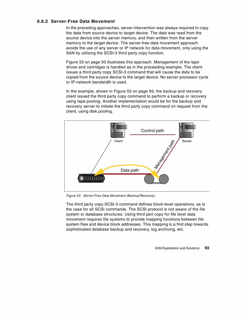
6.6.2 Server-Free Data MovementIn the preceding approaches, server intervention was always required to copythe data from source device to target device. The data was read from thesource device into the server memory, and then written from the servermemory to the target device. The server-free data movement approachavoids the use of any server or IP network for data movement, only using theSAN by utilizing the SCSI-3 third party copy function.
Figure 53 on page 93 illustrates this approach. Management of the tapedrives and cartridges is handled as in the proceeding example. The clientissues a third party copy SCSI-3 command that will cause the data to becopied from the source device to the target device. No server processor cycleor IP-network bandwidth is used.
In the example, shown in Figure 53 on page 93, the backup and recoveryclient issued the third party copy command to perform a backup or recoveryusing tape pooling. Another implementation would be for the backup andrecovery server to initiate the third party copy command on request from theclient, using disk pooling.
Figure 53. Server-Free Data Movement (Backup/Recovery)
The third party copy SCSI-3 command defines block-level operations, as isthe case for all SCSI commands. The SCSI protocol is not aware of the filesystem or database structures. Using third part copy for file level datamovement requires file systems to provide mapping functions between filesystem files and device block addresses. This mapping is a first step towardssophisticated database backup and recovery, log archiving, etc.
ServerClient
Man
agem
ent p
ath
Control path
Data path
SAN Exploitation and Solutions 93
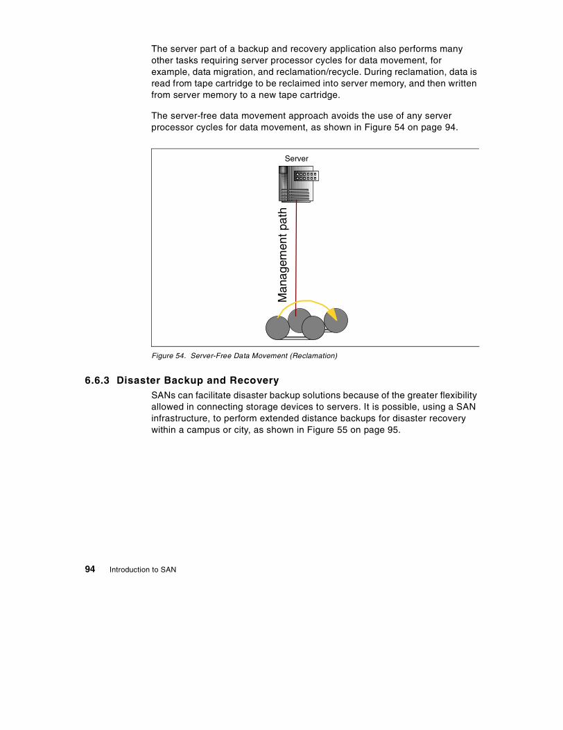
The server part of a backup and recovery application also performs manyother tasks requiring server processor cycles for data movement, forexample, data migration, and reclamation/recycle. During reclamation, data isread from tape cartridge to be reclaimed into server memory, and then writtenfrom server memory to a new tape cartridge.
The server-free data movement approach avoids the use of any serverprocessor cycles for data movement, as shown in Figure 54 on page 94.
Figure 54. Server-Free Data Movement (Reclamation)
6.6.3 Disaster Backup and RecoverySANs can facilitate disaster backup solutions because of the greater flexibilityallowed in connecting storage devices to servers. It is possible, using a SANinfrastructure, to perform extended distance backups for disaster recoverywithin a campus or city, as shown in Figure 55 on page 95.
Server
Man
agem
entp
ath
94 Introduction to SAN

Figure 55. Disaster Backup and Recovery
When longer distances are required, SANs must be connected usinggateways and WANs, similar to the situation discussed in 6.3.4, “ServerClustering” on page 81 and shown in Figure 46 on page 83.
Depending on business requirements, disaster protection implementationswill make use of copy services implemented in disk subsystems and tapelibraries (that might be implemented using SAN services), SAN copyservices, and most likely a combination of both.
Additionally, services and solutions — similar to Geographically DispersedParallel Sysplex (GDPS) for S/390, available today from IBM Global Services— will be required to monitor and manage these environments.
SAN Fabric
SAN Exploitation and Solutions 95

96 Introduction to SAN
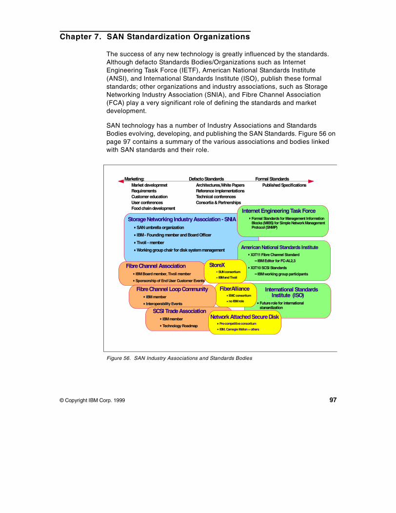
Chapter 7. SAN Standardization Organizations
The success of any new technology is greatly influenced by the standards.Although defacto Standards Bodies/Organizations such as InternetEngineering Task Force (IETF), American National Standards Institute(ANSI), and International Standards Institute (ISO), publish these formalstandards; other organizations and industry associations, such as StorageNetworking Industry Association (SNIA), and Fibre Channel Association(FCA) play a very significant role of defining the standards and marketdevelopment.
SAN technology has a number of Industry Associations and StandardsBodies evolving, developing, and publishing the SAN Standards. Figure 56 onpage 97 contains a summary of the various associations and bodies linkedwith SAN standards and their role.
Figure 56. SAN Industry Associations and Standards Bodies
International StandardsInstitute (ISO)
Futurerole for internationalstanardization
FiberAllianceEMCconsortium
no IBMrole
Marketing:Market developmnetRequirementsCustomer educationUser conferencesFoodchaindevelopment
DefactoStandardsArchitectures,White PapersReference implementationsTechnical conferencesConsortia &Partnerships
Formal StandardsPublished Specifications
StorageNetworking IndustryAssociation - SNIASANumbrella organization
IBM- Foundingmember andBoardOfficer
Tivoli - member
Workinggroupchair for disk systemmanagement
Internet Engineering Task ForceFormal Standardsfor Management InformationBlocks(MIBS) for Simple NetworkManagementProtocol (SNMP)
AmericanNational Standards InstituteX3T11Fibre Channel Standard
IBMEditor for FC-AL2,3
X3T10 SCSI Standards
IBMworking group participants
FibreChannel AssociationIBMBoard member, Tivoli member
Sponsorship of End User Customer Events
FibreChannel LoopCommunityIBMmember
Interoperability Events
SCSI TradeAssociationIBMmember
Technology Roadmap
StoreXSUNconsortium
IBMandTivoli
NetworkAttachedSecureDiskPre-competitiveconsortium
IBM, Carnegie Mellon+ others
© Copyright IBM Corp. 1999 97

IBM is actively participating in most of these organizations. Notice thepositioning of these organizations. We start from the left; these are themarketing oriented organizations. In the middle are the defacto standardsorganizations that are often industry partnerships formed to work on definingstandards. To the far right are the formal standards organizations.
The roles of these Associations and Bodies fall into three categories:
• Marketing oriented — (To the left in Figure 56 on page 97.)These associations architecture development organizations that areformed early in the product life-cycle, have marketing focus, and do themarket development, requirements, customer education, userconferences, and so on. This includes organizations are SNIA, FCA,Fibre Channel Loop Community (FCLC) and SCSI Trade Association(STA). Some of these organizations also help define the defacto industrystandards and thus have multiple roles.
• Defacto Standards oriented — (In the middle in Figure 56 on page 97.)These organizations and bodies, often industry partnerships, evolve thedefacto industry standards by defining the architectures, writing whitepapers, arranging technical conferences, and referencing implementationsbased on their association partners developments. They then submitthese specifications for formal standard acceptance and approval. Theyinclude organization such as SNIA, FCA, FCLC, StoreX, FibreAlliance.
• Formal standards oriented — (To the far right in Figure 56 on page 97.)These are the formal standards organizations like IETF, ANSI, and ISO,which are in place to review for approval and publish standards definedand submitted by the preceding two categories of organizations.
7.1 SAN Industry Associations and Organizations
A number of Industry Associations, alliances, consortium and formalstandards bodies are involved in the SAN standards; these include SNIA,FCA, FCLC, STA, StoreX, FibreAlliance, IETF, ANSI, and ISO. A briefdescription of the roles of some of these organization is given below.
7.1.1 Storage Networking Industry Association — SNIAStorage Networking Industry Association (SNIA) is an international computersystem industry forum of developers, integrators, and IT professionals whoevolve and promote storage networking technology and solutions. SNIA wasformed to ensure that storage networks become efficient, complete, andtrusted solutions across the IT community. SNIA can be classified as the SANUmbrella organization with over 100+ computer industry vendors as its
98 Introduction to SAN

members. IBM is one of the founding members of this organization. SNIA isuniquely committed to delivering architectures, education, and services thatwill propel storage networking solutions into a broader market. For additionalinformation on the various activities of SNIA, see its Web site at:
www.snia.org
7.1.2 Fibre Channel Association — FCAThe Fibre Channel Association (FCA) is organized as a not-for-profit, mutualbenefit corporation. The FCA mission is to nurture and help develop thebroadest market for Fibre Channel products. This is done through marketdevelopment, education, standards monitoring and fostering interoperabilityamong members' products. IBM is a board member in FCA. For additionalinformation on the various activities of FCA, see its Web site at:
www.fibrechannel.com
7.1.3 Fibre Channel Community — FClCThe Fibre Channel Community (FC/C) is a corporation consisting of morethan 100 computer industry-related companies. Like other working groups,the FC/C complements activities of the various standards committees. Itsgoal is to provide marketing support, exhibits, and trade shows for systemintegrators, peripheral manufacturers, software developers, componentmanufacturers, communications companies, consultants, and computerservice providers. The initial focus of the FC/C was on storage attachmentmigrating to network attached storage and solutions of FC-AL in networkingenvironments. FC is the foundation upon which broader implementation ofFibre Channel interconnect schemes, such as SANs, will be achieved. IBM isa member of FClC. For additional information on FClC, see its Web sites at:
www.fccommunity.org
www.fcloop.org
7.1.4 The SCSI Trade Association — STAThe SCSI Trade Association (STA) was formed to promote the use andunderstanding of small computer system interface (SCSI) parallel interfacetechnology. The STA provides a focal point for communicating SCSI benefitsto the market and influences the evolution of SCSI into the future. Foradditional information, see its Web site at:
www.scsita.org
SAN Standardization Organizations 99
7.1.5 Future I/OFuture I/O is a new I/O organization or consortium. Standards are beingdeveloped to maximize data transfer between next-generationhigh-performance servers and peripheral subsystems. The serverperformance will no longer be I/O bound. The standard will enable resilientand scalable, distributed computing through inter-processor clustering. Foradditional information, see its Web site at:
www.futureio.org
7.1.6 StoreXStoreX is a SUN Microsystems initiative to evolve a standard open platformfor storage software development using Java and Jini. IBM is a member ofthis consortium. For additional information on StoreX, see its Web site at:
java.sun.com/products/storex
7.1.7 Internet Engineering Task Force - IETFThe Internet Engineering Task Force (IETF) is a large open internationalcommunity of network designers, operators, vendors, and researchersconcerned with the evolution of the Internet architecture and the smoothoperation of the Internet. It is responsible for the formal standards for theManagement Information Blocks (MIB) for Simple Network ManagementProtocol (SNMP) for SAN management. For additional information on IETF,see its Web site a:
ietf.org
7.1.8 American National Standards Organization - ANSIAmerican National Standards Organization (ANSI) does not itself developAmerican national standards. It facilitates development by establishingconsensus among qualified groups. For Fibre Channel and Storage AreaNetworks, two of the important committees are: X3T11 Fibre ChannelStandard and X3T10 SCSI Standard. IBM is an editor of FC-AL 2,3 underX3T11, and IBM is also a working group participant in X3T10. For moreinformation on ANSI, see its Web site at:
www.ansi.org.
100 Introduction to SAN
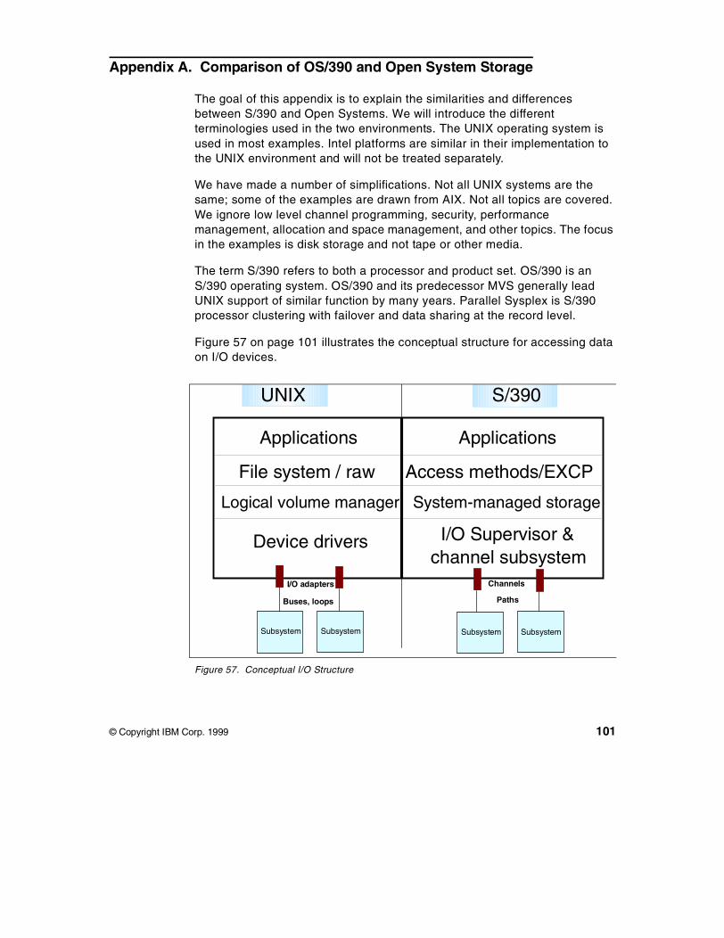
Appendix A. Comparison of OS/390 and Open System Storage
The goal of this appendix is to explain the similarities and differencesbetween S/390 and Open Systems. We will introduce the differentterminologies used in the two environments. The UNIX operating system isused in most examples. Intel platforms are similar in their implementation tothe UNIX environment and will not be treated separately.
We have made a number of simplifications. Not all UNIX systems are thesame; some of the examples are drawn from AIX. Not all topics are covered.We ignore low level channel programming, security, performancemanagement, allocation and space management, and other topics. The focusin the examples is disk storage and not tape or other media.
The term S/390 refers to both a processor and product set. OS/390 is anS/390 operating system. OS/390 and its predecessor MVS generally leadUNIX support of similar function by many years. Parallel Sysplex is S/390processor clustering with failover and data sharing at the record level.
Figure 57 on page 101 illustrates the conceptual structure for accessing dataon I/O devices.
Figure 57. Conceptual I/O Structure
Applications Applications
Logical volume manager System-managed storage
File system / raw Access methods/EXCP
I/O Supervisor &channel subsystem
Subsystem
I/O adapters Channels
Subsystem Subsystem Subsystem
Device drivers
Buses, loops Paths
UNIX S/390
© Copyright IBM Corp. 1999 101
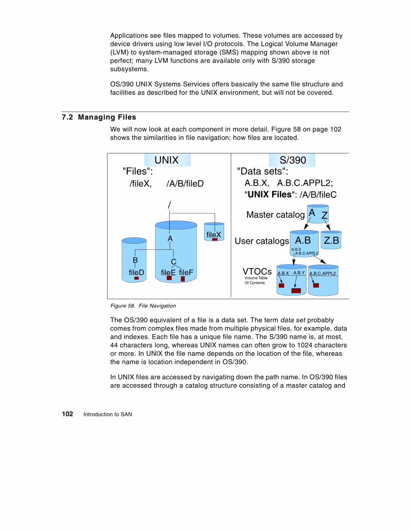
Applications see files mapped to volumes. These volumes are accessed bydevice drivers using low level I/O protocols. The Logical Volume Manager(LVM) to system-managed storage (SMS) mapping shown above is notperfect; many LVM functions are available only with S/390 storagesubsystems.
OS/390 UNIX Systems Services offers basically the same file structure andfacilities as described for the UNIX environment, but will not be covered.
7.2 Managing Files
We will now look at each component in more detail. Figure 58 on page 102shows the similarities in file navigation: how files are located.
Figure 58. File Navigation
The OS/390 equivalent of a file is a data set. The term data set probablycomes from complex files made from multiple physical files, for example, dataand indexes. Each file has a unique file name. The S/390 name is, at most,44 characters long, whereas UNIX names can often grow to 1024 charactersor more. In UNIX the file name depends on the location of the file, whereasthe name is location independent in OS/390.
In UNIX files are accessed by navigating down the path name. In OS/390 filesare accessed through a catalog structure consisting of a master catalog and
Master catalog
User catalogs
VTOCs
"Files": "Data sets":
A
A.B
A.B.X A.B.Y A.B.C.APPL2
fileXA
B
fileD
/fileX, /A/B/fileD
/
CfileE
A.B.X, A.B.C.APPL2;"UNIX Files": /A/B/fileC
fileF
Z
Z.BA.B.X
A.B.C.APPL2
Volume TableOf Contents
UNIX S/390
102 Introduction to SAN

one or more user catalogs. Catalogs tell you which volume a data set is on.Volume Tables Of Content (VTOCs) on the volumes contain the cylinder/tracklocation of the data set on the volume. OS/390 also supports UNIX files withina Hierarchical File System (HFS). This allows for UNIX applications to beported to OS/390 with minimum changes.
Figure 59 on page 103 illustrate how files are accessed in OS/390 and UNIX.
Figure 59. File Access
UNIX accesses files as a byte-stream of data, whereas OS/390 has recordoriented access. With the byte-stream access model, the application mustspecify the offset to the required data and the amount to be retrieved. Withrecord oriented access methods, the application requires a record at a time.
OS/390 supplies programs called access methods to simplify applicationaccess to data. Many access methods are supplied; each one is specializedfor a particular use. OS/390 allows raw access to a device through the EXCPaccess method. This function is seldom used by applications any more.
Byte-stream files
Ex: READ(fileid, buffer, length)
Databases implemented by"applications"; sometimes builton "raw" volumes outsideof file system
Access methods built into O/SEx: sequential, random, indexed
Record-oriented access
Ex: GET fileid,buffer
Databases implementedby "applications" using one ormore access methods (e.g., DB2)
Offset, length record1 record2 record3 record4
UNIX S/390
Comparison of OS/390 and Open System Storage 103
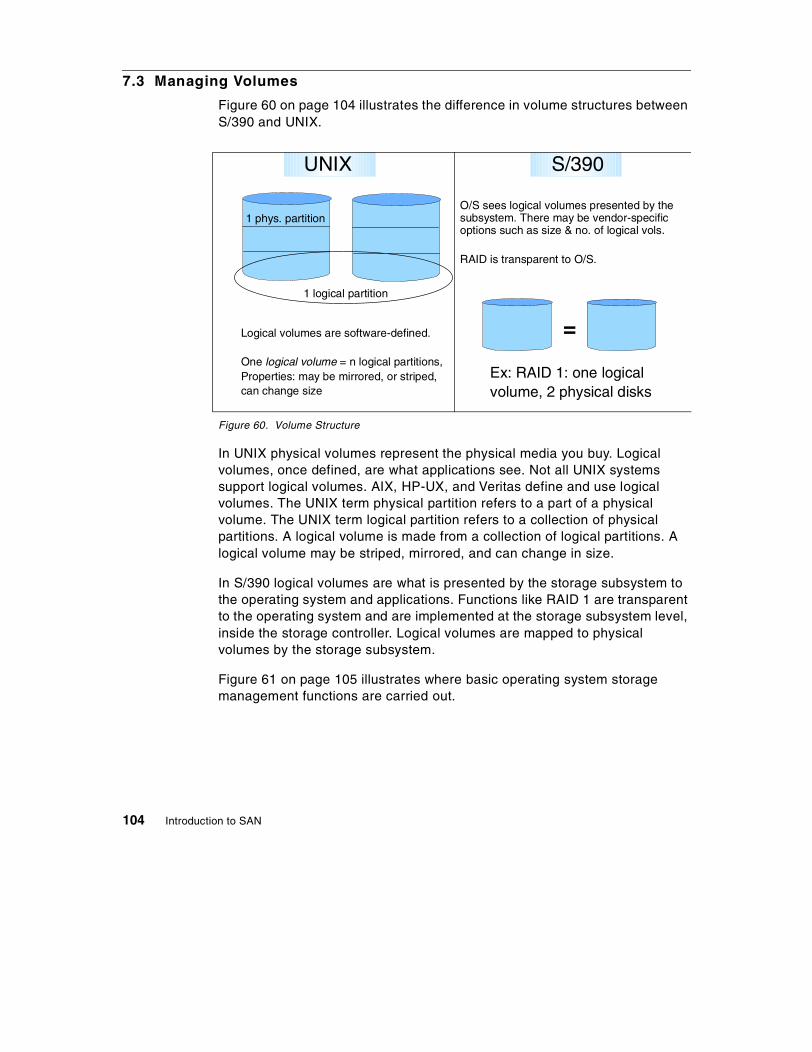
7.3 Managing Volumes
Figure 60 on page 104 illustrates the difference in volume structures betweenS/390 and UNIX.
Figure 60. Volume Structure
In UNIX physical volumes represent the physical media you buy. Logicalvolumes, once defined, are what applications see. Not all UNIX systemssupport logical volumes. AIX, HP-UX, and Veritas define and use logicalvolumes. The UNIX term physical partition refers to a part of a physicalvolume. The UNIX term logical partition refers to a collection of physicalpartitions. A logical volume is made from a collection of logical partitions. Alogical volume may be striped, mirrored, and can change in size.
In S/390 logical volumes are what is presented by the storage subsystem tothe operating system and applications. Functions like RAID 1 are transparentto the operating system and are implemented at the storage subsystem level,inside the storage controller. Logical volumes are mapped to physicalvolumes by the storage subsystem.
Figure 61 on page 105 illustrates where basic operating system storagemanagement functions are carried out.
Logical volumes are software-defined.
One logical volume = n logical partitions,Properties: may be mirrored, or striped,can change size
1 logical partition
1 phys. partition
Ex: RAID 1: one logicalvolume, 2 physical disks
O/S sees logical volumes presented by thesubsystem. There may be vendor-specificoptions such as size & no. of logical vols.
RAID is transparent to O/S.
=
UNIX S/390
104 Introduction to SAN
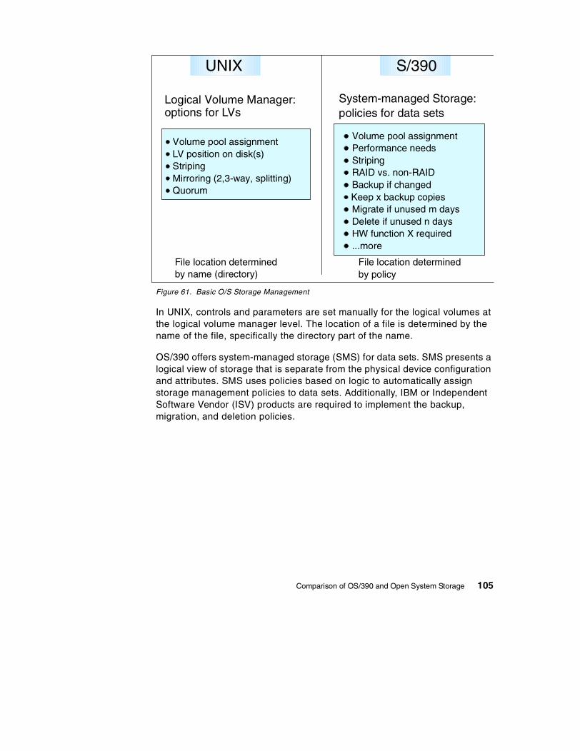
Figure 61. Basic O/S Storage Management
In UNIX, controls and parameters are set manually for the logical volumes atthe logical volume manager level. The location of a file is determined by thename of the file, specifically the directory part of the name.
OS/390 offers system-managed storage (SMS) for data sets. SMS presents alogical view of storage that is separate from the physical device configurationand attributes. SMS uses policies based on logic to automatically assignstorage management policies to data sets. Additionally, IBM or IndependentSoftware Vendor (ISV) products are required to implement the backup,migration, and deletion policies.
System-managed Storage:policies for data sets
Volume pool assignmentPerformance needsStripingRAID vs. non-RAIDBackup if changedKeep x backup copiesMigrate if unused m daysDelete if unused n daysHW function X required...more
Logical Volume Manager:options for LVs
Volume pool assignmentLV position on disk(s)StripingMirroring (2,3-way, splitting)Quorum
File location determinedby name (directory)
File location determinedby policy
UNIX S/390
Comparison of OS/390 and Open System Storage 105
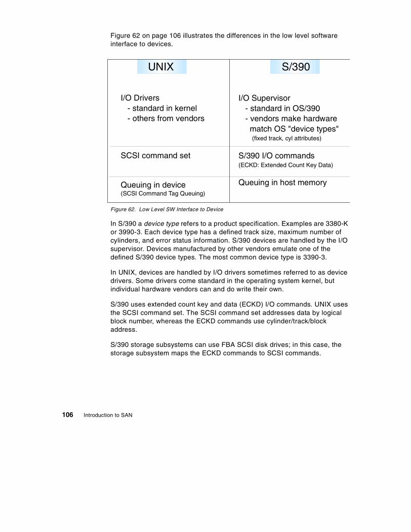
Figure 62 on page 106 illustrates the differences in the low level softwareinterface to devices.
Figure 62. Low Level SW Interface to Device
In S/390 a device type refers to a product specification. Examples are 3380-Kor 3990-3. Each device type has a defined track size, maximum number ofcylinders, and error status information. S/390 devices are handled by the I/Osupervisor. Devices manufactured by other vendors emulate one of thedefined S/390 device types. The most common device type is 3390-3.
In UNIX, devices are handled by I/O drivers sometimes referred to as devicedrivers. Some drivers come standard in the operating system kernel, butindividual hardware vendors can and do write their own.
S/390 uses extended count key and data (ECKD) I/O commands. UNIX usesthe SCSI command set. The SCSI command set addresses data by logicalblock number, whereas the ECKD commands use cylinder/track/blockaddress.
S/390 storage subsystems can use FBA SCSI disk drives; in this case, thestorage subsystem maps the ECKD commands to SCSI commands.
I/O Drivers- standard in kernel- others from vendors
SCSI command set
Queuing in device(SCSI Command Tag Queuing)
I/O Supervisor- standard in OS/390- vendors make hardware
match OS "device types"(fixed track, cyl attributes)
S/390 I/O commands(ECKD: Extended Count Key Data)
Queuing in host memory
UNIX S/390
106 Introduction to SAN

OS/390 issues one I/O per logical volume; other I/Os are queued in processormemory. With the Enterprise Storage Server in OS/390 environments, I/Osare queued in the storage servers, and up to 8 concurrent I/Os requests canbe executed in parallel for a logical volume. In SCSI devices queueing isperformed at the device.
7.4 Storage Device Attachment
Figure 63 on page 107 outlines how the processor to storage interactionoccurs.
Figure 63. Processor to Storage Interface
In S/390, storage adapters are supplied by the processor manufacturer. Theadapters do not support RAID or cache. In UNIX, storage adapters aresupplied by the processor manufacturer or third parties. Some adapters dosupport caching and RAID.
S/390 supports up to 8 paths per OS image to each device, and pathmanagement is off-loaded to the channel subsystem. In UNIX environments,multi path support, if any, is performed by additional software.
Adapters, often from third parties;some support RAID or cache
Multi-path support, if any,done by driver, software fromsubsystem vendor, or ISV software
Adapters from processor manufacturer;no RAID or cache on adapter
Up to 8 paths per OS image to device
Path management offloaded toprocessor Channel Subsystem
Processor
Adapter
UNIX S/390
Comparison of OS/390 and Open System Storage 107

Figure 64 on page 108 shows the various ways in which a device can beconnected to the device adapter on the processor.
Figure 64. I/O Device Attachment
S/390 uses the Original Equipment Manufacturer's Interface (OEMI) adapter.OEMI allowed data transfer rates of up to 4.5 MB/sec. ESCON wasintroduced in 1991 and allows data rates of up to 17 MB/sec half duplex. Therecent introduction of FICON allows for data rates of up to 100 MB/sec fullduplex. The ESCON or FICON storage director is a switch and allows fullbandwidth along each connection.
The SCSI protocol is based on and evolved from the OEMI standard. SCSIprotocol has evolved over the years, and current implementation (SCSI-3)allows for SCSI commands to be sent over Fibre Channel (FC) connections.
S/390 disks are connected behind storage controllers. These controllersshow external interfaces to the processor that are different from the internalinterfaces. In UNIX systems often the disks are Just a Bunch Of Disks(JBOD) with direct attach to SCSI adapters. Today, storage controllers suchas the ESS, with different upper and lower interfaces, are becoming morecommon.
Processormicroproc
bus
SSA /FCAdapter
SCSIAdapter
SCSI bus
microproc
bus
OEMIAdapter
ESCONor FICONAdapter
Bus&Tag cables
Director
Processor
(ESCON = Enterprise Systems Connection)(FICON = Fibre Connection)(OEMI =Original Equipment Manufacturer's Interface)
FCAdapter FC hub
loop
UNIX S/390
108 Introduction to SAN
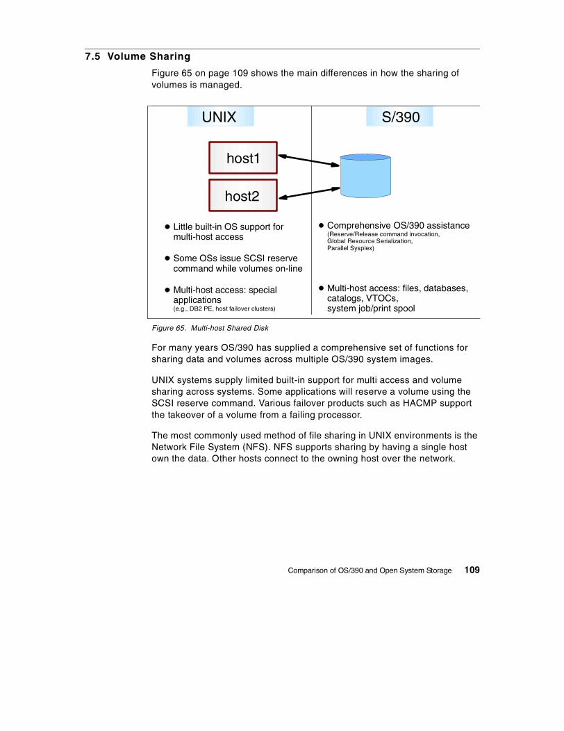
7.5 Volume Sharing
Figure 65 on page 109 shows the main differences in how the sharing ofvolumes is managed.
Figure 65. Multi-host Shared Disk
For many years OS/390 has supplied a comprehensive set of functions forsharing data and volumes across multiple OS/390 system images.
UNIX systems supply limited built-in support for multi access and volumesharing across systems. Some applications will reserve a volume using theSCSI reserve command. Various failover products such as HACMP supportthe takeover of a volume from a failing processor.
The most commonly used method of file sharing in UNIX environments is theNetwork File System (NFS). NFS supports sharing by having a single hostown the data. Other hosts connect to the owning host over the network.
Little built-in OS support formulti-host access
Some OSs issue SCSI reservecommand while volumes on-line
Multi-host access: specialapplications(e.g., DB2 PE, host failover clusters)
Comprehensive OS/390 assistance(Reserve/Release command invocation,Global Resource Serialization,Parallel Sysplex)
Multi-host access: files, databases,catalogs, VTOCs,system job/print spool
host1
host2
UNIX S/390
Comparison of OS/390 and Open System Storage 109

7.6 Caching
Figure 66 on page 110 illustrates the main differences in caching betweenS/390 and UNIX environments.
Figure 66. Cache Considerations
In S/390, files are allocated in contiguous tracks and cylinders. Outboardcache storage is used extensively in this environment because data isgenerally stored continuously. Sequential prefetch can be performedeffectively by the storage subsystem because the data is stored continuously.
In UNIX, systems files are allocated in small blocks and these blocks may benon-contiguous. UNIX knows the location of non-contiguous blocks, and so itcan perform its own sequential prefetch. UNIX uses processor memory forread cache operations.
Because OS/390 is designed for multi-system data sharing, use of memoryas a read-cache may require extensive cross-system coordination. This isgenerally limited to catalogs and Parallel Sysplex databases andapplications.
In both environments writes can be delayed by using non-volatile storage inthe storage subsystem.
Host
Subsys
Files allocated in smallblocks; may not becontiguous
Processor memoryused as read cache(file system, databases)
Many writes delayed
Files allocated incontinuous tracksand cylinders
Outboard cache effective;some use of Data in Memory
Many writes delayed
Seek Rotate Xfer
UNIX S/390
Memory
Controller
Cache
110 Introduction to SAN
Appendix B. Special Notices
This publication is intended to help storage administrators, systemprogrammers, system administrators, and other technical support staffs tounderstand the concept of Storage Area Networks and what functionality andbenefits it gives. The information in this publication is not intended as thespecification of any programming interfaces that are provided by describedproducts. See the PUBLICATIONS section of the IBM ProgrammingAnnouncement for each described product for more information about whatpublications are considered to be product documentation.
References in this publication to IBM products, programs or services do notimply that IBM intends to make these available in all countries in which IBMoperates. Any reference to an IBM product, program, or service is notintended to state or imply that only IBM's product, program, or service may beused. Any functionally equivalent program that does not infringe any of IBM'sintellectual property rights may be used instead of the IBM product, programor service.
Information in this book was developed in conjunction with use of theequipment specified, and is limited in application to those specific hardwareand software products and levels.
IBM may have patents or pending patent applications covering subject matterin this document. The furnishing of this document does not give you anylicense to these patents. You can send license inquiries, in writing, to the IBMDirector of Licensing, IBM Corporation, North Castle Drive, Armonk, NY10504-1785.
Licensees of this program who wish to have information about it for thepurpose of enabling: (i) the exchange of information between independentlycreated programs and other programs (including this one) and (ii) the mutualuse of the information which has been exchanged, should contact IBMCorporation, Dept. 600A, Mail Drop 1329, Somers, NY 10589 USA.
Such information may be available, subject to appropriate terms andconditions, including in some cases, payment of a fee.
The information contained in this document has not been submitted to anyformal IBM test and is distributed AS IS. The information about non-IBM("vendor") products in this manual has been supplied by the vendor and IBMassumes no responsibility for its accuracy or completeness. The use of thisinformation or the implementation of any of these techniques is a customerresponsibility and depends on the customer's ability to evaluate and integrate
© Copyright IBM Corp. 1999 111

them into the customer's operational environment. While each item may havebeen reviewed by IBM for accuracy in a specific situation, there is noguarantee that the same or similar results will be obtained elsewhere.Customers attempting to adapt these techniques to their own environmentsdo so at their own risk.
Any pointers in this publication to external Web sites are provided forconvenience only and do not in any manner serve as an endorsement ofthese Web sites.
This document contains examples of data and reports used in daily businessoperations. To illustrate them as completely as possible, the examplescontain the names of individuals, companies, brands, and products. All ofthese names are fictitious and any similarity to the names and addressesused by an actual business enterprise is entirely coincidental.
The following terms are trademarks of the International Business MachinesCorporation in the United States and/or other countries:
The following terms are trademarks of other companies:
C-bus is a trademark of Corollary, Inc. in the United States and/or othercountries.
Java and all Java-based trademarks and logos are trademarks or registeredtrademarks of Sun Microsystems, Inc. in the United States and/or othercountries.
Microsoft, Windows, Windows NT, and the Windows logo are trademarks ofMicrosoft Corporation in the United States and/or other countries.
AIX AS/400AT CTDB2 DFSMSDFSMShsm ECKDESCON IBM Magstar MVS/XANetfinity OS/2OS/390 OS/400Parallel Sysplec RAMACRS/6000 S/390Seascape SPStorWatch System/390Versatile Storage Server 400
112 Introduction to SAN

PC Direct is a trademark of Ziff Communications Company in the UnitedStates and/or other countries and is used by IBM Corporation under license.
ActionMedia, LANDesk, MMX, Pentium and ProShare are trademarks of IntelCorporation in the United States and/or other countries.
UNIX is a registered trademark in the United States and/or other countrieslicensed exclusively through X/Open Company Limited.
SET and the SET logo are trademarks owned by SET Secure ElectronicTransaction LLC.
Other company, product, and service names may be trademarks or servicemarks of others.
Special Notices 113

114 Introduction to SAN

Appendix C. Related Publications
The publications listed in this section are considered particularly suitable for amore detailed discussion of the topics covered in this redbook.
C.1 International Technical Support Organization Publications
For information on ordering these ITSO publications see “How to Get ITSORedbooks” on page 117.
• Data Sharing: Implementing Copy-Sharing Solutions AmongHeterogeneous Systems, SG24-4120
• Storage Area Networks: Tape Future In Fabrics, SG24-5474
• IBM Magstar 3494 Tape Libraries: A Practical Guide, SG24-4632
• IBM Versatile Storage Server, SG24-2221
• Implementing the Enterprise Storage Server in Your Environment,SG24-5420
• Planning for IBM Remote Copy, SG24-2595
• IBM Enterprise Storage Server, SG24-5465
• IBM Storage Solutions for Server Consolidation, SG24-5355
• Principles of Enterprise Storage Management, SG24-5250
© Copyright IBM Corp. 1999 115
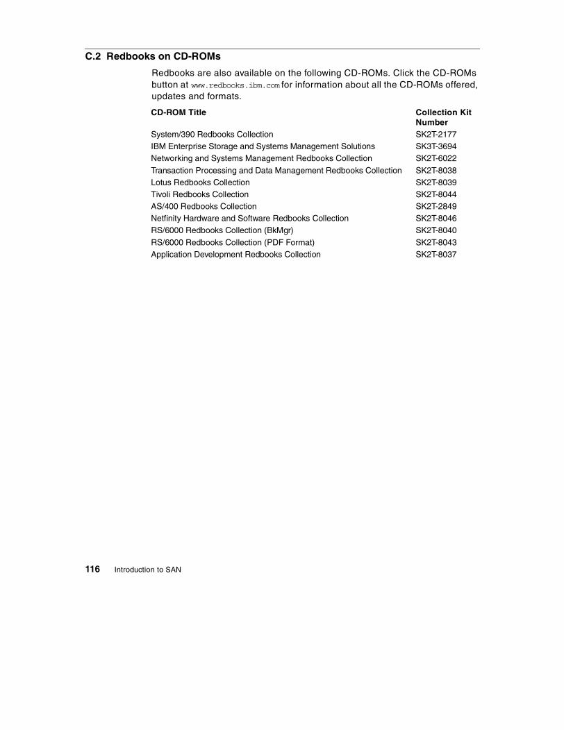
C.2 Redbooks on CD-ROMs
Redbooks are also available on the following CD-ROMs. Click the CD-ROMsbutton at www.redbooks.ibm.com for information about all the CD-ROMs offered,updates and formats.
CD-ROM Title Collection KitNumber
System/390 Redbooks Collection SK2T-2177IBM Enterprise Storage and Systems Management Solutions SK3T-3694Networking and Systems Management Redbooks Collection SK2T-6022
Transaction Processing and Data Management Redbooks Collection SK2T-8038Lotus Redbooks Collection SK2T-8039Tivoli Redbooks Collection SK2T-8044AS/400 Redbooks Collection SK2T-2849Netfinity Hardware and Software Redbooks Collection SK2T-8046RS/6000 Redbooks Collection (BkMgr) SK2T-8040
RS/6000 Redbooks Collection (PDF Format) SK2T-8043Application Development Redbooks Collection SK2T-8037
116 Introduction to SAN
How to Get ITSO Redbooks
This section explains how both customers and IBM employees can find out about ITSO redbooks,redpieces, and CD-ROMs. A form for ordering books and CD-ROMs by fax or e-mail is also provided.
• Redbooks Web Site http://www.redbooks.ibm.com/
Search for, view, download, or order hardcopy/CD-ROM redbooks from the redbooks Web site. Alsoread redpieces and download additional materials (code samples or diskette/CD-ROM images) fromthis redbooks site.
Redpieces are redbooks in progress; not all redbooks become redpieces and sometimes just a fewchapters will be published this way. The intent is to get the information out much quicker than theformal publishing process allows.
• E-mail Orders
Send orders by e-mail including information from the redbooks fax order form to:
• Telephone Orders
• Fax Orders
This information was current at the time of publication, but is continually subject to change. The latestinformation may be found at the redbooks Web site.
In United StatesOutside North America
e-mail [email protected] information is in the “How to Order” section at this site:http://www.elink.ibmlink.ibm.com/pbl/pbl/
United States (toll free)Canada (toll free)Outside North America
1-800-879-27551-800-IBM-4YOUCountry coordinator phone number is in the “How to Order”section at this site:http://www.elink.ibmlink.ibm.com/pbl/pbl/
United States (toll free)CanadaOutside North America
1-800-445-92691-403-267-4455Fax phone number is in the “How to Order” section at this site:http://www.elink.ibmlink.ibm.com/pbl/pbl/
IBM employees may register for information on workshops, residencies, and redbooks by accessingthe IBM Intranet Web site at http://w3.itso.ibm.com/ and clicking the ITSO Mailing List button.Look in the Materials repository for workshops, presentations, papers, and Web pages developedand written by the ITSO technical professionals; click the Additional Materials button. Employeesmay access MyNews at http://w3.ibm.com/ for redbook, residency, and workshop announcements.
IBM Intranet for Employees
© Copyright IBM Corp. 1999 117

IBM Redbook Fax Order Form
Please send me the following:
We accept American Express, Diners, Eurocard, Master Card, and Visa. Payment by credit card notavailable in all countries. Signature mandatory for credit card payment.
Title Order Number Quantity
First name Last name
Company
Address
City Postal code
Telephone number Telefax number VAT number
Invoice to customer number
Country
Credit card number
Credit card expiration date SignatureCard issued to
118 Introduction to SAN

Glossary
8B/10B A data encoding scheme developed byIBM, translating byte-wide data to an encoded10-bit format. Fibre Channel's FC-1 leveldefines this as the method to be used to encodeand decode data transmissions over the Fibrechannel.
Adapter A hardware unit that aggregates otherI/O units, devices or communications links to asystem bus.
ADSM Adstar Distributed Storage Manager
Agent (1) In the client-server model, the part ofthe system that performs informationpreparation and exchange on behalf of a clientor server application. (2) In SNMP, the wordagent refers to the managed system. See also:Management Agent
AIT Advanced Intelligent Tape - A magnetictape format by Sony that uses 8mm cassettes,but is only used in specific drives.
AL See Arbitrated Loop
ANSI American National Standards Institute -The primary organization for fostering thedevelopment of technology standards in theUnited States. The ANSI family of Fibre Channeldocuments provide the standards basis for theFibre Channel architecture and technology. SeeFC-PH
Arbitration The process of selecting onerespondent from a collection of severalcandidates that request service concurrently.
Arbitrated Loop A Fibre Channelinterconnection technology that allows up to 126participating node ports and one participatingfabric port to communicate.
ATL Automated Tape Library - Large scale tapestorage system, which uses multiple tape drivesand mechanisms to address 50 or morecassettes.
ATM Asynchronous Transfer Mode - A type ofpacket switching that transmits fixed-lengthunits of data.
© Copyright IBM Corp. 1999
Backup A copy of computer data that is used torecreate data that has been lost, mislaid,corrupted, or erased. The act of creating a copyof computer data that can be used to recreatedata that has been lost, mislaid, corrupted orerased.
Bandwidth Measure of the information capacityof a transmission channel.
Bridge (1) A component used to attach morethan one I/O unit to a port. (2) A datacommunications device that connects two ormore networks and forwards packets betweenthem. The bridge may use similar or dissimilarmedia and signaling systems. It operates at thedata link level of the OSI model. Bridges readand filter data packets and frames.
Bridge/Router A device that can provide thefunctions of a bridge, router or bothconcurrently. A bridge/router can route one ormore protocols, such as TCP/IP, and bridge allother traffic. See also: Bridge, Router
Broadcast Sending a transmission to allN_Ports on a fabric.
Channel A point-to-point link, the main task ofwhich is to transport data from one point toanother.
Channel I/O A form of I/O where request andresponse correlation is maintained throughsome form of source, destination and requestidentification.
CIFS Common Internet File System
Class of Service A Fibre Channel framedelivery scheme exhibiting a specified set ofdelivery characteristics and attributes.
Class-1 A class of service providing dedicatedconnection between two ports with confirmeddelivery or notification of non-deliverability.
Class-2 A class of service providing a frameswitching service between two ports withconfirmed delivery or notification ofnon-deliverability.
119
Class-3 A class of service providing frameswitching datagram service between two ports ora multicast service between a multicast originatorand one or more multicast recipients.
Class-4 A class of service providing a fractionalbandwidth virtual circuit between two ports withconfirmed delivery or notification ofnon-deliverability.
Class-6 A class of service providing a multicastconnection between a multicast originator andone or more multicast recipients with confirmeddelivery or notification of non-deliverability.
Client A software program used to contact andobtain data from a server software program onanother computer -- often across a greatdistance. Each client program is designed to workspecifically with one or more kinds of serverprograms and each server requires a specifickind of client program.
Client/Server The relationship betweenmachines in a communications network. Theclient is the requesting machine, the server thesupplying machine. Also used to describe theinformation management relationship betweensoftware components in a processing system.
Cluster A type of parallel or distributed systemthat consists of a collection of interconnectedwhole computers and is used as a single, unifiedcomputing resource.
Coaxial Cable A transmission media (cable)used for high speed transmission. It is calledcoaxial because it includes one physical channelthat carries the signal surrounded (after a layer ofinsulation) by another concentric physicalchannel, both of which run along the same axis.The inner channel carries the signal and the outerchannel serves as a ground.
Controller A component that attaches to thesystem topology through a channel semanticprotocol that includes some form ofrequest/response identification.
CRC Cyclic Redundancy Check - Anerror-correcting code used in Fibre Channel.
DASD Direct Access Storage Device - anyon-line storage device: a disc, drive or CD-ROM.
DAT Digital Audio Tape - A tape mediatechnology designed for very high quality audiorecording and data backup. DAT cartridges looklike audio cassettes and are often used inmechanical auto-loaders. typically, a DATcartridge provides 2GB of storage. But new DATsystems have much larger capacities.
Data Sharing A SAN solution in which files on astorage device are shared between multiplehosts.
Datagram Refers to the Class 3 Fibre ChannelService that allows data to be sent rapidly tomultiple devices attached to the fabric, with noconfirmation of delivery.
dB Decibel - a ratio measurement distinguishingthe percentage of signal attenuation between theinput and output power. Attenuation (loss) isexpressed as dB/km
Disk Mirroring A fault-tolerant technique thatwrites data simultaneously to two hard disksusing the same hard disk controller.
Disk Pooling A SAN solution in which diskstorage resources are pooled across multiplehosts rather than be dedicated to a specific host.
DLT Digital Linear Tape - A magnetic tapetechnology originally developed by DigitalEquipment Corporation (DEC) and now sold byQuantum. DLT cartridges provide storagecapacities from 10 to 35GB.
E_Port Expansion Port - a port on a switch usedto link multiple switches together into a FibreChannel switch fabric.
ECL Emitter Coupled Logic - The type oftransmitter used to drive copper media such asTwinax, Shielded Twisted Pair, or Coax.
Enterprise Network A geographically dispersednetwork under the auspices of one organization.
Entity In general, a real or existing thing from theLatin ens, or being, which makes the distinctionbetween a thing's existence and it qualities. Inprogramming, engineering and probably manyother contexts, the word is used to identify units,whether concrete things or abstract ideas, thathave no ready name or label.
120 Introduction to SAN

ESCON Enterprise System Connection
Exchange A group of sequences which share aunique identifier. All sequences within a givenexchange use the same protocol. Frames frommultiple sequences can be multiplexed to preventa single exchange from consuming all thebandwidth. See also: Sequence
F_Node Fabric Node - a fabric attached node.
F_Port Fabric Port - a port used to attach a NodePort (N_Port) to a switch fabric.
Fabric Fibre Channel employs a fabric to connectdevices. A fabric can be as simple as a singlecable connecting two devices. The term is mostoften used to describe a more complex networkutilizing hubs, switches and gateways.
Fabric Login Fabric Login (FLOGI) is used by anN_Port to determine if a fabric is present and, ifso, to initiate a session with the fabric byexchanging service parameters with the fabric.Fabric Login is performed by an N_Port followinglink initialization and before communication withother N_Ports is attempted.
FC Fibre Channel
FC-0 Lowest level of the Fibre Channel Physicalstandard, covering the physical characteristics ofthe interface and media
FC-1 Middle level of the Fibre Channel Physicalstandard, defining the 8B/10B encoding/decodingand transmission protocol.
FC-2 Highest level of the Fibre Channel Physicalstandard, defining the rules for signaling protocoland describing transfer of frame, sequence andexchanges.
FC-3 The hierarchical level in the Fibre Channelstandard that provides common services such asstriping definition.
FC-4 The hierarchical level in the Fibre Channelstandard that specifies the mapping ofupper-layer protocols to levels below.
FCA Fiber Channel Association.
FC-AL Fibre Channel Arbitrated Loop - Areference to the Fibre Channel Arbitrated Loopstandard, a shared gigabit media for up to 127
nodes, one of which may be attached to a switchfabric. See also: Arbitrated Loop.
FC-CT Fibre Channel common transport protocol
FC-FG Fibre Channel Fabric Generic - Areference to the document (ANSI X3.289-1996)which defines the concepts, behavior andcharacteristics of the Fibre Channel Fabric alongwith suggested partitioning of the 24-bit addressspace to facilitate the routing of frames.
FC-FP Fibre Channel HIPPI Framing Protocol - Areference to the document (ANSI X3.254-1994)defining how the HIPPI framing protocol istransported via the fibre channel
FC-GS Fibre Channel Generic Services -Areference to the document (ANSI X3.289-1996)describing a common transport protocol used tocommunicate with the server functions, a fullX500 based directory service, mapping of theSimple Network Management Protocol (SNMP)directly to the Fibre Channel, a time server andan alias server.
FC-LE Fibre Channel Link Encapsulation - Areference to the document (ANSI X3.287-1996)which defines how IEEE 802.2 Logical LinkControl (LLC) information is transported via theFibre Channel.
FC-PH A reference to the Fibre Channel Physicaland Signaling standard ANSI X3.230, containingthe definition of the three lower levels (FC-0,FC-1, and FC-2) of the Fibre Channel.
FC-PLDA Fibre Channel Private Loop DirectAttach - See PLDA.
FC-SB Fibre Channel Single Byte CommandCode Set - A reference to the document (ANSIX.271-1996) which defines how the ESCONcommand set protocol is transported using thefibre channel.
FC-SW Fibre Channel Switch Fabric - Areference to the ANSI standard underdevelopment that further defines the fabricbehavior described in FC-FG and defines thecommunications between different fabricelements required for those elements tocoordinate their operations and managementaddress assignment.
121
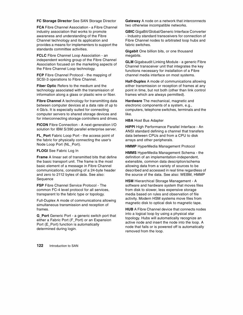
FC Storage Director See SAN Storage Director
FCA Fibre Channel Association - a Fibre Channelindustry association that works to promoteawareness and understanding of the FibreChannel technology and its application andprovides a means for implementers to support thestandards committee activities.
FCLC Fibre Channel Loop Association - anindependent working group of the Fibre ChannelAssociation focused on the marketing aspects ofthe Fibre Channel Loop technology.
FCP Fibre Channel Protocol - the mapping ofSCSI-3 operations to Fibre Channel.
Fiber Optic Refers to the medium and thetechnology associated with the transmission ofinformation along a glass or plastic wire or fiber.
Fibre Channel A technology for transmitting databetween computer devices at a data rate of up to4 Gb/s. It is especially suited for connectingcomputer servers to shared storage devices andfor interconnecting storage controllers and drives.
FICON Fibre Connection - A next-generation I/Osolution for IBM S/390 parallel enterprise server.
FL_Port Fabric Loop Port - the access point ofthe fabric for physically connecting the user'sNode Loop Port (NL_Port).
FLOGI See Fabric Log In
Frame A linear set of transmitted bits that definethe basic transport unit. The frame is the mostbasic element of a message in Fibre Channelcommunications, consisting of a 24-byte headerand zero to 2112 bytes of data. See also:Sequence
FSP Fibre Channel Service Protocol - Thecommon FC-4 level protocol for all services,transparent to the fabric type or topology.
Full-Duplex A mode of communications allowingsimultaneous transmission and reception offrames.
G_Port Generic Port - a generic switch port thateither a Fabric Port (F_Port) or an ExpansionPort (E_Port) function is automaticallydetermined during login.
Gateway A node on a network that interconnectstwo otherwise incompatible networks.
GBIC GigaBit/Global/Generic Interface Converter- Industry standard transceivers for connection ofFibre Channel nodes to arbitrated loop hubs andfabric switches.
Gigabit One billion bits, or one thousandmegabits.
GLM Gigabaudit Linking Module - a generic FibreChannel transceiver unit that integrates the keyfunctions necessary for installation of a Fibrechannel media interface on most systems.
Half-Duplex A mode of communications allowingeither transmission or reception of frames at anypoint in time, but not both (other than link controlframes which are always permitted).
Hardware The mechanical, magnetic andelectronic components of a system, e.g.,computers, telephone switches, terminals and thelike.
HBA Host Bus Adapter
HIPPI High Performance Parallel Interface - AnANSI standard defining a channel that transfersdata between CPUs and from a CPU to diskarrays and other peripherals.
HMMP HyperMedia Management Protocol
HMMS HyperMedia Management Schema - thedefinition of an implementation-independent,extensible, common data description/schemaallowing data from a variety of sources to bedescribed and accessed in real time regardless ofthe source of the data. See also: WEBM, HMMP
HSM Hierarchical Storage Management - Asoftware and hardware system that moves filesfrom disk to slower, less expensive storagemedia based on rules and observation of fileactivity. Modern HSM systems move files frommagnetic disk to optical disk to magnetic tape.
HUB A Fibre Channel device that connects nodesinto a logical loop by using a physical startopology. Hubs will automatically recognize anactive node and insert the node into the loop. Anode that fails or is powered off is automaticallyremoved from the loop.
122 Introduction to SAN
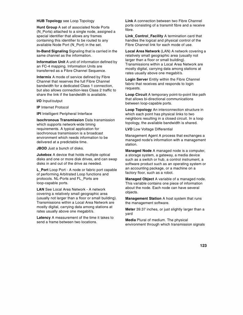
HUB Topology see Loop Topology
Hunt Group A set of associated Node Ports(N_Ports) attached to a single node, assigned aspecial identifier that allows any framescontaining this identifier to be routed to anyavailable Node Port (N_Port) in the set.
In-Band Signaling Signaling that is carried in thesame channel as the information.
Information Unit A unit of information defined byan FC-4 mapping. Information Units aretransferred as a Fibre Channel Sequence.
Intermix A mode of service defined by FibreChannel that reserves the full Fibre Channelbandwidth for a dedicated Class 1 connection,but also allows connection-less Class 2 traffic toshare the link if the bandwidth is available.
I/O Input/output
IP Internet Protocol
IPI Intelligent Peripheral Interface
Isochronous Transmission Data transmissionwhich supports network-wide timingrequirements. A typical application forisochronous transmission is a broadcastenvironment which needs information to bedelivered at a predictable time.
JBOD Just a bunch of disks.
Jukebox A device that holds multiple opticaldisks and one or more disk drives, and can swapdisks in and out of the drive as needed.
L_Port Loop Port - A node or fabric port capableof performing Arbitrated Loop functions andprotocols. NL-Ports and FL_Ports areloop-capable ports.
LAN See Local Area Network - A networkcovering a relatively small geographic area(usually not larger than a floor or small building).Transmissions within a Local Area Network aremostly digital, carrying data among stations atrates usually above one megabit/s.
Latency A measurement of the time it takes tosend a frame between two locations.
Link A connection between two Fibre Channelports consisting of a transmit fibre and a receivefibre.
Link_Control_Facility A termination card thathandles the logical and physical control of theFibre Channel link for each mode of use.
Local Area Network (LAN) A network covering arelatively small geographic area (usually notlarger than a floor or small building).Transmissions within a Local Area Network aremostly digital, carrying data among stations atrates usually above one megabit/s.
Login Server Entity within the Fibre Channelfabric that receives and responds to loginrequests.
Loop Circuit A temporary point-to-point like paththat allows bi-directional communicationsbetween loop-capable ports.
Loop Topology An interconnection structure inwhich each point has physical links to twoneighbors resulting in a closed circuit. In a looptopology, the available bandwidth is shared.
LVD Low Voltage Differential
Management Agent A process that exchanges amanaged node's information with a managementstation.
Managed Node A managed node is a computer,a storage system, a gateway, a media devicesuch as a switch or hub, a control instrument, asoftware product such as an operating system oran accounting package, or a machine on afactory floor, such as a robot.
Managed Object A variable of a managed node.This variable contains one piece of informationabout the node. Each node can have severalobjects.
Management Station A host system that runsthe management software.
Meter 39.37 inches, or just slightly larger than ayard
Media Plural of medium. The physicalenvironment through which transmission signals
123
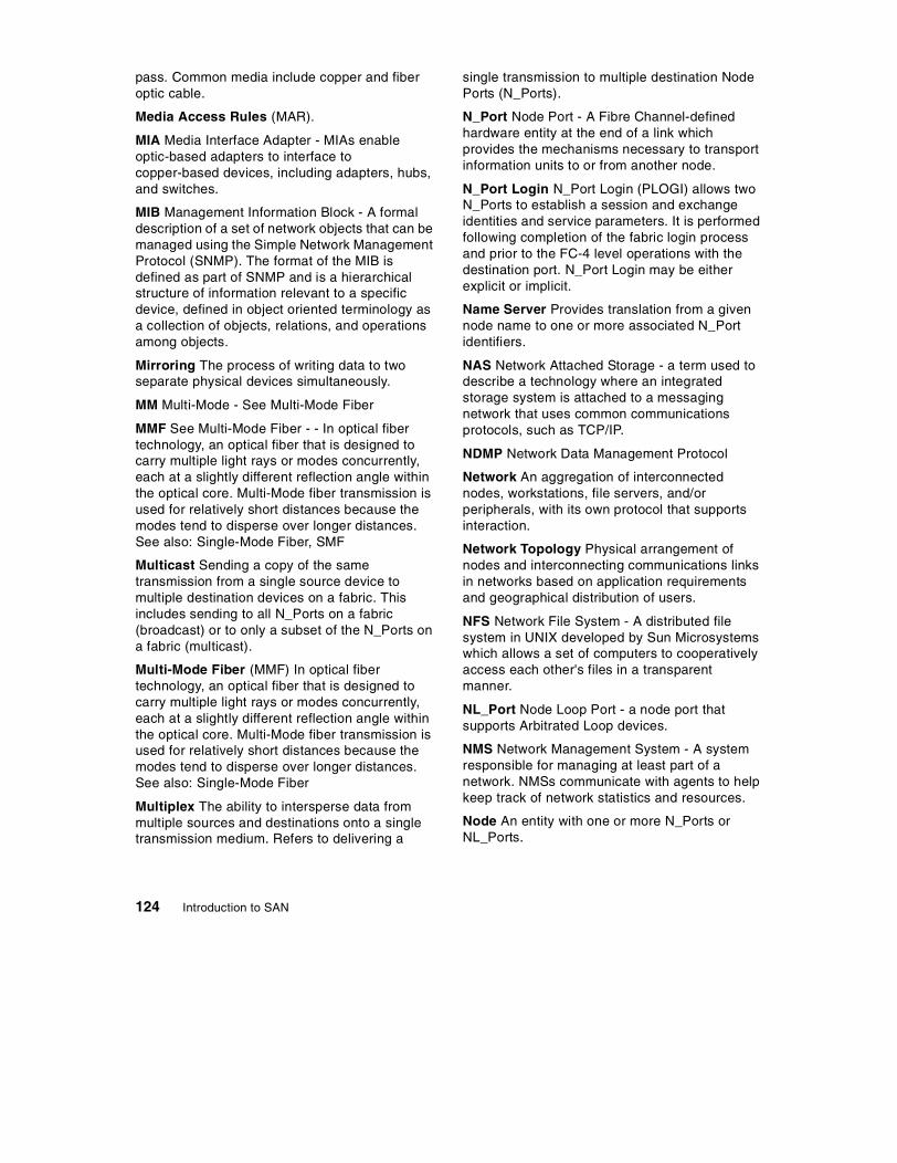
pass. Common media include copper and fiberoptic cable.
Media Access Rules (MAR).
MIA Media Interface Adapter - MIAs enableoptic-based adapters to interface tocopper-based devices, including adapters, hubs,and switches.
MIB Management Information Block - A formaldescription of a set of network objects that can bemanaged using the Simple Network ManagementProtocol (SNMP). The format of the MIB isdefined as part of SNMP and is a hierarchicalstructure of information relevant to a specificdevice, defined in object oriented terminology asa collection of objects, relations, and operationsamong objects.
Mirroring The process of writing data to twoseparate physical devices simultaneously.
MM Multi-Mode - See Multi-Mode Fiber
MMF See Multi-Mode Fiber - - In optical fibertechnology, an optical fiber that is designed tocarry multiple light rays or modes concurrently,each at a slightly different reflection angle withinthe optical core. Multi-Mode fiber transmission isused for relatively short distances because themodes tend to disperse over longer distances.See also: Single-Mode Fiber, SMF
Multicast Sending a copy of the sametransmission from a single source device tomultiple destination devices on a fabric. Thisincludes sending to all N_Ports on a fabric(broadcast) or to only a subset of the N_Ports ona fabric (multicast).
Multi-Mode Fiber (MMF) In optical fibertechnology, an optical fiber that is designed tocarry multiple light rays or modes concurrently,each at a slightly different reflection angle withinthe optical core. Multi-Mode fiber transmission isused for relatively short distances because themodes tend to disperse over longer distances.See also: Single-Mode Fiber
Multiplex The ability to intersperse data frommultiple sources and destinations onto a singletransmission medium. Refers to delivering a
single transmission to multiple destination NodePorts (N_Ports).
N_Port Node Port - A Fibre Channel-definedhardware entity at the end of a link whichprovides the mechanisms necessary to transportinformation units to or from another node.
N_Port Login N_Port Login (PLOGI) allows twoN_Ports to establish a session and exchangeidentities and service parameters. It is performedfollowing completion of the fabric login processand prior to the FC-4 level operations with thedestination port. N_Port Login may be eitherexplicit or implicit.
Name Server Provides translation from a givennode name to one or more associated N_Portidentifiers.
NAS Network Attached Storage - a term used todescribe a technology where an integratedstorage system is attached to a messagingnetwork that uses common communicationsprotocols, such as TCP/IP.
NDMP Network Data Management Protocol
Network An aggregation of interconnectednodes, workstations, file servers, and/orperipherals, with its own protocol that supportsinteraction.
Network Topology Physical arrangement ofnodes and interconnecting communications linksin networks based on application requirementsand geographical distribution of users.
NFS Network File System - A distributed filesystem in UNIX developed by Sun Microsystemswhich allows a set of computers to cooperativelyaccess each other's files in a transparentmanner.
NL_Port Node Loop Port - a node port thatsupports Arbitrated Loop devices.
NMS Network Management System - A systemresponsible for managing at least part of anetwork. NMSs communicate with agents to helpkeep track of network statistics and resources.
Node An entity with one or more N_Ports orNL_Ports.
124 Introduction to SAN

Non-Blocking A term used to indicate that thecapabilities of a switch are such that the totalnumber of available transmission paths is equalto the number of ports. Therefore, all ports canhave simultaneous access through the switch.
Non-L_Port A Node or Fabric port that is notcapable of performing the Arbitrated Loopfunctions and protocols. N_Ports and F_Ports arenot loop-capable ports.
Operation A term defined in FC-2 that refers toone of the Fibre Channel building blockscomposed of one or more, possibly concurrent,exchanges.
Optical Disk A storage device that is written andread by laser light.
Optical Fiber A medium and the technologyassociated with the transmission of informationas light pulses along a glass or plastic wire orfiber.
Ordered Set A Fibre Channel term referring tofour 10 -bit characters (a combination of data andspecial characters) providing low-level linkfunctions, such as frame demarcation andsignaling between two ends of a link.
Originator A Fibre Channel term referring to theinitiating device.
Out of Band Signaling Signaling that isseparated from the channel carrying theinformation.
Peripheral Any computer device that is not partof the essential computer (the processor, memoryand data paths) but is situated relatively close by.A near synonym is input/output (I/O) device.
PLDA Private Loop Direct Attach - A technicalreport which defines a subset of the relevantstandards suitable for the operation of peripheraldevices such as disks and tapes on a privateloop.
PLOGI See N_Port Login
Point-to-Point Topology An interconnectionstructure in which each point has physical links toonly one neighbor resulting in a closed circuit. Inpoint-to-point topology, the available bandwidththe is dedicated
Port The hardware entity within a node thatperforms data communications over the FibreChannel.
Port Bypass Circuit A circuit used in hubs anddisk enclosures to automatically open or closethe loop to add or remove nodes on the loop.
Private NL_Port An NL_Port which does notattempt login with the fabric and onlycommunicates with other NL Ports on the sameloop.
Protocol A data transmission conventionencompassing timing, control, formatting anddata representation.
Public NL_Port An NL_Port that attempts loginwith the fabric and can observe the rules of eitherpublic or private loop behavior. A public NL_Portmay communicate with both private and publicNL_Ports.
Quality of Service (QoS) A set ofcommunications characteristics required by anapplication. Each QoS defines a specifictransmission priority, level of route reliability, andsecurity level.
RAID Redundant Array of Inexpensive orIndependent Disks. A method of configuringmultiple disk drives in a storage subsystem forhigh availability and high performance.
Raid 0 Level 0 RAID support - Striping, noredundancy
Raid 1 Level 1 RAID support - mirroring,complete redundancy
Raid 5 Level 5 RAID support, Striping with parity
Repeater A device that receives a signal on anelectromagnetic or optical transmission medium,amplifies the signal, and then retransmits it alongthe next leg of the medium.
Responder A Fibre Channel term referring to theanswering device.
Router (1) A device that can decide which ofseveral paths network traffic will follow based onsome optimal metric. Routers forward packetsfrom one network to another based onnetwork-layer information. (2) A dedicated
125
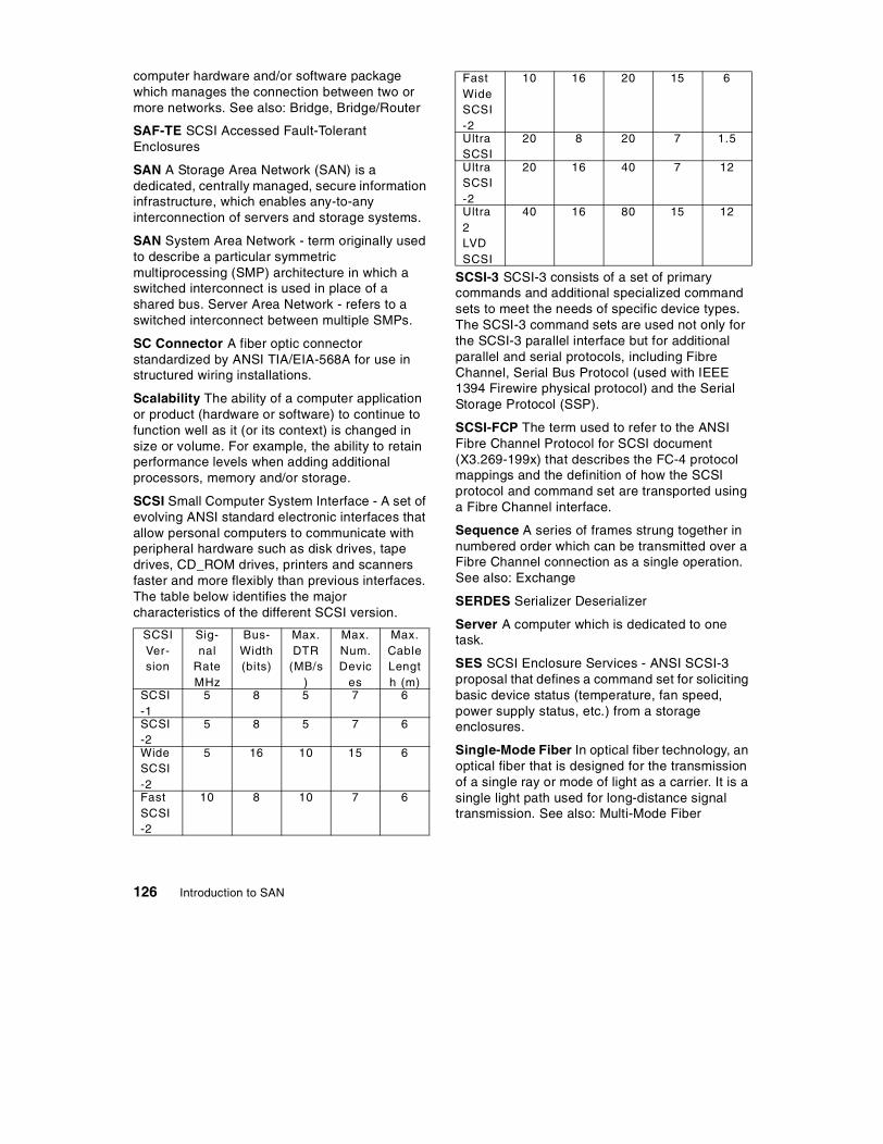
computer hardware and/or software packagewhich manages the connection between two ormore networks. See also: Bridge, Bridge/Router
SAF-TE SCSI Accessed Fault-TolerantEnclosures
SAN A Storage Area Network (SAN) is adedicated, centrally managed, secure informationinfrastructure, which enables any-to-anyinterconnection of servers and storage systems.
SAN System Area Network - term originally usedto describe a particular symmetricmultiprocessing (SMP) architecture in which aswitched interconnect is used in place of ashared bus. Server Area Network - refers to aswitched interconnect between multiple SMPs.
SC Connector A fiber optic connectorstandardized by ANSI TIA/EIA-568A for use instructured wiring installations.
Scalability The ability of a computer applicationor product (hardware or software) to continue tofunction well as it (or its context) is changed insize or volume. For example, the ability to retainperformance levels when adding additionalprocessors, memory and/or storage.
SCSI Small Computer System Interface - A set ofevolving ANSI standard electronic interfaces thatallow personal computers to communicate withperipheral hardware such as disk drives, tapedrives, CD_ROM drives, printers and scannersfaster and more flexibly than previous interfaces.The table below identifies the majorcharacteristics of the different SCSI version.
SCSI-3 SCSI-3 consists of a set of primarycommands and additional specialized commandsets to meet the needs of specific device types.The SCSI-3 command sets are used not only forthe SCSI-3 parallel interface but for additionalparallel and serial protocols, including FibreChannel, Serial Bus Protocol (used with IEEE1394 Firewire physical protocol) and the SerialStorage Protocol (SSP).
SCSI-FCP The term used to refer to the ANSIFibre Channel Protocol for SCSI document(X3.269-199x) that describes the FC-4 protocolmappings and the definition of how the SCSIprotocol and command set are transported usinga Fibre Channel interface.
Sequence A series of frames strung together innumbered order which can be transmitted over aFibre Channel connection as a single operation.See also: Exchange
SERDES Serializer Deserializer
Server A computer which is dedicated to onetask.
SES SCSI Enclosure Services - ANSI SCSI-3proposal that defines a command set for solicitingbasic device status (temperature, fan speed,power supply status, etc.) from a storageenclosures.
Single-Mode Fiber In optical fiber technology, anoptical fiber that is designed for the transmissionof a single ray or mode of light as a carrier. It is asingle light path used for long-distance signaltransmission. See also: Multi-Mode Fiber
SCSIVer-sion
Sig-nal
RateMHz
Bus-Width(bits)
Max.DTR
(MB/s)
Max.Num.Devic
es
Max.CableLength (m)
SCSI-1
5 8 5 7 6
SCSI-2
5 8 5 7 6
WideSCSI-2
5 16 10 15 6
FastSCSI-2
10 8 10 7 6
FastWideSCSI-2
10 16 20 15 6
UltraSCSI
20 8 20 7 1.5
UltraSCSI-2
20 16 40 7 12
Ultra2LVDSCSI
40 16 80 15 12
126 Introduction to SAN

SMART Self Monitoring and ReportingTechnology
SM Single Mode - See Single-Mode Fiber
SMF Single-Mode Fiber - See Single-Mode Fiber.In optical fiber technology, an optical fiber that isdesigned for the transmission of a single ray ormode of light as a carrier. It is a single light pathused for long-distance signal transmission. Seealso: MMF
SNIA Storage Networking Industry Association. Anon-profit organization comprised of more than77 companies and individuals in the storageindustry.
SN Storage Network. See also: SAN
SNMP Simple Network Management Protocol -The Internet network management protocol whichprovides a means to monitor and set networkconfiguration and run-time parameters.
SNMWG Storage Network Management WorkingGroup is chartered to identify, define and supportopen standards needed to address the increasedmanagement requirements imposed by storagearea network environments.
SSA Serial Storage Architecture - A high speedserial loop-based interface developed as a highspeed point-to-point connection for peripherals,particularly high speed storage arrays, RAID andCD-ROM storage by IBM.
Star The physical configuration used with hubs inwhich each user is connected by communicationslinks radiating out of a central hub that handles allcommunications.
Storewatch Expert These are Storewatchapplications that employ a 3 tiered architecturethat includes a management interface, aStorewatch manager and agents that run on thestorage resource(s) being managed. Expertproducts employ a Storewatch data base that canbe used for saving key management data (e.g.capacity or performance metrics). Expertproducts use the agents as well as analysis ofstorage data saved in the data base to performhigher value functions including -- reporting ofcapacity, performance, etc. over time (trends),configuration of multiple devices based on
policies, monitoring of capacity and performance,automated responses to events or conditions,and storage related data mining.
StoreWatch Specialist A Storewatch interfacefor managing an individual fibre Channel deviceor a limited number of like devices (that can beviewed as a single group). StorWatch specialiststypically provide simple, point-in-timemanagement functions such as configuration,reporting on asset and status information, simpledevice and event monitoring, and perhaps someservice utilities.
Striping A method for achieving higherbandwidth using multiple N_Ports in parallel totransmit a single information unit across multiplelevels.
STP Shielded Twisted Pair
Storage Media The physical device itself, ontowhich data is recorded. Magnetic tape, opticaldisks, floppy disks are all storage media.
Switch A component with multiple entry/exitpoints (ports) that provides dynamic connectionbetween any two of these points.
Switch Topology An interconnection structure inwhich any entry point can be dynamicallyconnected to any exit point. In a switch topology,the available bandwidth is scalable.
T11 A technical committee of the NationalCommittee for Information TechnologyStandards, titled T11 I/O Interfaces. It is taskedwith developing standards for moving data in andout of computers.
Tape Backup Making magnetic tape copies ofhard disk and optical disc files for disasterrecovery.
Tape Pooling A SAN solution in which taperesources are pooled and shared across multiplehosts rather than being dedicated to a specifichost.
TCP Transmission Control Protocol - a reliable,full duplex, connection-oriented end-to-endtransport protocol running on top of IP.
TCP/IP Transmission Control Protocol/ InternetProtocol - a set of communications protocols that
127

support peer-to-peer connectivity functions forboth local and wide area networks.
Time Server A Fibre Channel-defined servicefunction that allows for the management of alltimers used within a Fibre Channel system.
Topology An interconnection scheme that allowsmultiple Fibre Channel ports to communicate. Forexample, point-to-point, Arbitrated Loop, andswitched fabric are all Fibre Channel topologies.
Twinax A transmission media (cable) consistingof two insulated central conducting leads ofcoaxial cable.
Twisted Pair A transmission media (cable)consisting of two insulated copper wires twistedaround each other to reduce the induction (thusinterference) from one wire to another. Thetwists, or lays, are varied in length to reduce thepotential for signal interference between pairs.Several sets of twisted pair wires may beenclosed in a single cable. This is the mostcommon type of transmission media.
ULP Upper Level Protocols
UTC Under-The-Covers, a term used tocharacterize a subsystem in which a smallnumber of hard drives are mounted inside ahigher function unit. The power and cooling areobtained from the system unit. Connection is byparallel copper ribbon cable or pluggablebackplane, using IDE or SCSI protocols.
UTP Unschielded Twisted Pair
Virtual Circuit A unidirectional path between twocommunicating N_Ports that permits fractionalbandwidth.
WAN Wide Area Network - A network whichencompasses inter-connectivity between devicesover a wide geographic area. A wide areanetwork may be privately owned or rented, butthe term usually connotes the inclusion of public(shared) networks.
WDM Wave Division Multiplexing - A technologythat puts data from different sources together onan optical fiber, with each signal carried on itsown separate light wavelength. Using WDM, upto 80 (and theoretically more) separate
wavelengths or channels of data can bemultiplexed into a stream of light transmitted on asingle optical fiber.
WEBM Web-Based Enterprise Management - Aconsortium working on the development of aseries of standards to enable active managementand monitoring of network-based elements.
Zoning In Fibre Channel environments, thegrouping together of multiple ports to form avirtual private storage network. Ports that aremembers of a group or zone can communicatewith each other but are isolated from ports inother zones.
128 Introduction to SAN
List of Abbreviations
ADSM Adstar DistributedStorage Manager
AFS Andrews File System
ANSI American NationalStandards Institute
ASCII American StandardCode for InformationInterchange
ATA AT Attachment
CCW Channel CommandWord
CIM Common InterfaceModel
DFSMS Data Facility StorageManagementSubsystem
DMI Desktop ManagementInterface
EBCDIC Extended BinaryCommunication DataInterchange Code
ECKD Extended Count keyand Data
EIDE Enhanced IntegratedDrive Electronics
ERP Enterprise ResourcePlanning
ESCON Enterprise SystemsConnection
ESRM Enterprise StorageResource Management
FC Fibre Channel
FCA Fibre channelAssociation
FC-AL Fibre ChannelArbitrated Loop
FClC Fibre Channel LoopCommunity
© Copyright IBM Corp. 1999
FCIC Fibre ChannelInter-Connect
FE Fibre Element
FICON Fibre Connection
FL Fibre Loop
GB GigaByte
Gb GigaBit
GBIC Gigabit InterfaceConverters
GLM Giga Bit Link Module
HA High Availability
HBA Host Bus Adaptor
HFS Hierarchical FileSystem
HIPPI High PerformanceParallel Interface
I/O Input Output
IBM International BusinessMachines Corporation
IDE Integrated DriveElectronics
IETF Internet EngineeringTask Force
IIS Intelligent StorageServer
IP Internet protocol
ISO International StandardsOrganization
ISV Independent SoftwareVendor
IT Information Technology
ITSO International TechnicalSupport Organization
JBOD Just a bunch of Disks
JFS Journalling File System
129

JMAPI Java ManagementApplicationProgramming Interface
LAN Local Area Network
LIP Loop InitializationProtocol
LVM Logical VolumeManager
MAR Media Access Rules
MB Mega Byte
MIA Media InterfaceAdapters
MIB ManagementInformation Block
MMF Multi Mode Fibre
NAS Network AttachedStorage
NC Network Computer
NFS Network File System
NTFS NT File System
PBC Port Bypass Circuit
PPRC Peer to peer RemoteCopy
RAID Redundant Array ofInexpensive Disks
ROI Return on Investment
S/390 System 390
SAN Storage Area Network
SCSI Small ComputerSystems Interface
SES SCSI EnclosureServices
SLS Single Level Storage
SMB Server Message Block
SMF Single Mode Fibre
SMS System ManagedStorage
SNIA Storage NetworkingIndustry Association
SNMP Simple NetworkManagement Protocol
SPD System ProductDivision
SSA Serial StorageArchitecture
SSD Storage systemsDivision
STA SCSI Trade Association
TCP/IP Transmission ControlProtocol / InternetProtocol
TIMI TechnologyIndependent MachineInterface
ULTRA ATA Ultra AT Attachment
VSAM Virtual Storage AccessMethod
VTOC Volume Table ofContents
WAN Wide Area Network
WEBM WEB Management
XRC Extended Remote Copy
130 Introduction to SAN

Index
Numerics24x7 29, 90
AAcknowledged
Connection 10Connectionless 10
added value 75ADSM 24, 71, 73AFS 41, 44AIX 2, 31, 42, 43, 73, 78, 84, 85, 86, 88ANSI 8, 65any-to-any 20, 22, 23, 29, 31, 34, 35, 56, 64application
availability 4performance 4
arbitrated loop 7, 9, 14, 50, 53, 54, 57, 58, 60, 64,70, 71AS/400 44, 45ASCII 42, 88ATA 6
Ultra 6Authorization 28availability 29
Bbandwidth 49, 53, 54, 55, 57, 59, 89, 91bridge 12, 14, 23, 33, 50, 60, 76building blocks 8, 75, 76Bus and Tag 43, 49bus-attached storage 50business
benefits 77model 11objectives 11value 34
Ccable 65caching 5cascade 15, 55, 56centralization 28CIM 67Class 1 10
Class 2 10Class 3 10Class 4 10Class 6 10Client/Server 1, 2, 38, 51clustering 17clusters and sectors 41company asset 1Computers
Network 2Personal 2
Concurrent Copy 20consolidated storage 4, 40control unit 5, 16copper 8, 12, 13, 58, 64cost and functionality 63cross-platform 30
Ddata
backup 17consistency 90consolidation 40encoding 19, 42, 58integrity 30intensive 27interchange 17, 19mining 27pipe 19protection 17, 38sharing 17, 29, 83vaulting 17
DB2 Parallel Edition 19DEC 2, 23, 31, 39decision support 27device address 79DFSMS 71DFSMShsm 73disaster recovery 17discovery 68disk pooling 83distance 2, 5, 6, 12, 16, 39, 40, 77, 82DMI 67downsizing 1, 28downtime 71, 82, 90dual copy 5dual power supply 16dynamic pathing 74
131

EEBCDIC 42, 88e-business 11, 27, 29ECKD 41e-commerce 27education 76EIDE 6emerging Web technologies 68encoding 9, 88endians 42end-to-end solutions 34ERP 27ESCON 1, 2, 5, 6, 13, 14, 15, 23, 33, 37, 39, 41,43, 77, 78ESCON Director 5, 14, 15, 43, 55, 59ESCON Manager 5, 24ESRM 20, 21, 69, 71ESS 22, 24, 73Ethernet 14, 19, 51, 52, 60, 70extender 39
Ffabric 15, 23, 32, 49, 53, 54, 55, 56, 66, 71, 76failover 3, 14, 19fanout 15, 54FAT 78FC
connectivity 33loop 57
FC-0 9FC-1 9FC-2 9FC-3 9FC-4 6, 9, 40FC-AL 7, 14, 37, 40, 43, 46, 65, 69, 70, 71FCP 6, 8, 9, 10, 14, 37, 40, 52, 64FC-SB-2 6FDDI 52, 60, 69fiber 8, 12, 13, 23, 39, 58, 64Fibre Channel 2, 3, 6, 8, 9, 10, 12, 13, 15, 23, 24,29, 40, 43, 44, 46, 49, 50, 52, 53, 54, 55, 58, 59,65, 66, 71, 77, 90FICON 6, 8, 9, 10, 14, 15, 16, 33, 37, 40, 41, 43,52
bridge 16Director 59
filecopy-sharing 86
server 4structures 19systems 19
first SAN 23FL 58Flashcopy 20flat file transfer 18floating point 42flow control 9Fractional Bandwidth Connection 10Frame Relay 70frame switch 9framing protocol 9full duplex 6, 53
Ggateway 2, 12, 19, 23, 33, 43, 49, 52, 60, 65, 71,76
Hhalf-duplex 5, 39HBA 13, 57, 64, 65heterogeneous 11, 17, 18, 19, 20, 27, 28, 29, 30,32, 35, 40, 41, 64, 67, 78, 83, 84, 87, 88hierarchy 89high availability 74HIPPI 3homogeneous 11, 17, 18, 19, 59, 87host-centric 1HP 2, 23, 31, 39, 42, 73hub 2, 9, 13, 19, 49, 50, 54, 57, 58, 65, 71, 76
intelligent 14
IIBM 3466 51IBM 7133 39IBM SAN Data Gateway 60, 74IDE 6IGS 35Improved performance 29In-Band 70infrastructure 11integrity 28INTEL-based 46interoperability 20, 32inter-switch link 56, 65inter-vendor interoperability 66
132 Introduction to SAN

Inventory 68IP 8, 9, 64, 66, 70, 87
network terminology 12islands of information 40
JJFS 41, 44JMAPI 67
LLAN 2, 3, 4, 12, 15, 19, 51, 65, 66, 69, 70, 89LAN-less 19, 89, 91licence information 21LIP 78load balancing 34, 74, 82logical view 22loop 7, 9, 15, 40, 53, 54, 57, 71, 78LUN 79LUN-masking 79
Mmanagement 33, 66
advanced functions 34applications 66, 77architecture 66asset 69, 72, 74availability 69capability 50capacity 69, 72centrally 4, 29, 31, 34, 64configuration 69, 72consolidated storage 39costs 1distributed 68end-to-end 30, 50enterprise storage 69fabric 33information 68interfaces 68levels 64performance 69, 72service 72software 7, 78solutions 38, 67, 69storage policy 72strategy 69total cost of 63
manufacturer 21MAR 58MIB 66
extensions 66fabric element 66Fibre Channel InterConnect 66standard 66
micro-kernel 51migration path 23mirroring 20, 38, 74
remote 39MMF 12model information 21multicast 9, 10multi-drop 14Multi-Mode 12multi-mode 16, 64multi-platform 32, 35multi-vendor 7
solutions 30MVS/ESA 59MVS/XA 5
NName services 68NAS 4, 51, 52NetBOIS 8network
architecture 17behind the server 19centric 27
NFS 4, 51, 85, 87NIC 13node-to-node 9non-cascaded 55non-disruptive addition 78non-IBM subsystems 71, 78non-S/390 8, 10, 59Novell 45NSM 51, 73NTFS 41, 78
OObject-based 45OEMI 43, 77one-at-a-time 39, 87Oracle Parallel 19OS/2 73
133

OS/390 2, 11, 19, 31, 33, 39, 40, 42, 43, 45, 59,73, 78, 81, 83, 84, 85, 86, 88OS/400 2, 31, 39, 42, 45, 46outboard data movement 4, 34, 89, 90outbord data movement 90Out-of-Band 70
PParallel Sysplex 19, 82path-to-data selection 34PBC 14PC 6, 39, 42PCI 45physical media 9piping 18planning 68platform-independent 22, 33point-in-time 87point-to-point 9, 23, 40, 53, 54, 56, 58, 60, 71
virtual 54pooling 78, 83
disk 34, 46, 78file 84tape 34, 46, 80
PPRC 20, 90preemption 10primary network 19, 20purchase decision 29
RRAID 29, 38, 73RAID 1 5reconfigure 7redundancy 34remote copy 20, 38, 46, 90remote mirroring 4, 77Removable media 71rightsizing 1, 28ROI 34, 35router 2, 15, 19, 20, 52, 60, 76RS/6000 43, 44
cluster 19RS-232 70
SS/390 1, 5, 6, 10, 16, 24, 39, 40, 42, 43, 78, 79, 82SAN 31
fabric 76IBM Initiative 32
SAN Pyramid 33, 37, 49, 63, 75scalability 28scalable performance 55scratch groups 81SCSI 2, 6, 7, 8, 9, 13, 14, 29, 33, 37, 39, 41, 43,46, 49, 52, 60, 65, 70, 73, 77, 82
Accelerator 77differential 77LVD 77single-ended 77
SCSI-1 37SCSI-3 37, 64, 65, 89Seascape architecture 41Secure transactions 28security 28, 68self-configure 58self-discovering 54Sequent 23server consolidation 11, 84server to server 3, 76server to storage 3, 76server-centric 50server-free 19, 89, 90, 91Servers 76Services 76SES 65
queries 65SGI 2, 31, 39share tape resources 80shared repository 17Simplex Connection 10simultaneous
read access 87read and write access 87
single-level storage 42, 45single-mode 12, 16, 64sizing 21SLIP connection 70SLS 45, 46SMF 12SMS 24SNA 8SnapShot 20SNIA 30, 35, 66SNMP 4, 20, 65, 66, 70
agent 66manager 66
134 Introduction to SAN

Software 77information 21
solutions 32SPD 45SSA 3, 6, 7, 33, 37, 39, 43, 46, 71, 72standards 30, 35, 67
based environment 30organizations 24
star 53Storage 76storage
consolidation 29, 30, 34, 40, 41, 84partitioning 83, 84server-attached 4sharing 29
storage to storage 4, 76StorWatch 24, 69, 71striping 85SUN 2, 23, 31, 39, 42, 73, 84, 85, 86, 88support 76switch 2, 9, 13, 14, 19, 20, 21, 33, 49, 50, 52, 54,55, 56, 57, 58, 59, 65, 66, 71, 76, 78switched 9, 15, 40, 53, 56, 71System Managed Storage 24
TT-0 copy 90tape sharing 46TCP/IP 14, 51, 60third party copy 89TIMI 44, 45Tivoli 33Token Ring 52, 69, 70toolbox 75TPF 43traditional network 3transmission rates 9transport service 9true data sharing 34, 84, 86tunneling 14
UUltra SCSI 60Unacknowledged Connectionless 10universal access to data 32, 38UNIX 2, 6, 11, 23, 31, 39, 40, 42, 43, 44, 45, 46,78, 83
Vvaulting 19vendor selection 64Virtual resource 28, 30VM 43VM/ESA 59volume grouping 85VSAM 41VSE 43VSS 24, 72, 73
WWAN 2, 12, 15, 19, 51, 61, 65, 66, 70, 82, 89warm standby 20WBEM 20, 67Windows NT 2, 11, 23, 31, 39, 40, 42, 45, 46, 73,78, 83, 84, 85, 86, 88
XXRC 20, 90
Zzoning 16, 68, 74, 79
135

136 Introduction to SAN

© Copyright IBM Corp. 1999 137
ITSO Redbook Evaluation
Introduction to Storage Area Network, SANSG24-5470-00
Your feedback is very important to help us maintain the quality of ITSO redbooks. Please completethis questionnaire and return it using one of the following methods:
• Use the online evaluation form found at www.redbooks.ibm.com/• Fax this form to: USA International Access Code + 1 914 432 8264• Send your comments in an Internet note to [email protected]
Which of the following best describes you?_ Customer _ Business Partner _ Solution Developer _ IBM employee_ None of the above
Please rate your overall satisfaction with this book using the scale:(1 = very good, 2 = good, 3 = average, 4 = poor, 5 = very poor)
Overall Satisfaction __________
Please answer the following questions:
Was this redbook published in time for your needs? Yes___ No___
If no, please explain:
What other redbooks would you like to see published?
Comments/Suggestions: (THANK YOU FOR YOUR FEEDBACK!)
Printed in the U.S.A.
SG24-5470-00
Introduction
toStorage
Area
Netw
ork,S
AN
SG
24-5470-00