Embed Size (px)
Citation preview

Copyright Sangoma 2012 - 1 - 8/10/2012
This admin guide covers firmware release 8.8
for both SIP and H.323 protocols.
Vega Gateway
Administration Guide
Configuration and
Management of E1T1,
BRI and FXS/FXO Vega
Telephony Gateways

Vega Admin Guide R8.8 V1.1
Copyright Sangoma 2012 - 2 - 8/10/2012
Contents
1 INTRODUCTION ................................................................................................................................. 8
2 POWER ON SELF TEST ..................................................................................................................... 9
2.1 POWER ON SELF TEST (POST) ............................................................................................................. 9 2.2 RESULTS .............................................................................................................................................. 9 2.3 STATUS LED FLASH PATTERNS .......................................................................................................... 9
3 VEGA IP ADDRESS ............................................................................................................................. 9
3.1 DHCP BEHAVIOUR AND CONFIGURATION .......................................................................................... 10 DHCP Enabled ......................................................................................................................................... 10 DHCP Disabled ........................................................................................................................................ 12
3.2 DETERMINING THE VEGA’S IP ADDRESS ON FXS GATEWAYS ............................................................ 13
4 DUAL BOOT H.323 / SIP ................................................................................................................... 14
4.1 DUAL BOOT INTRODUCTION ............................................................................................................... 14 4.2 BOOT MANAGER AND AUTOEXEC INTERACTION .................................................................................. 14
5 USER INTERFACES .......................................................................................................................... 15
5.1 COMMAND LINE INTERFACE (CLI) ..................................................................................................... 15 Serial Connection ...................................................................................................................................... 15 Telnet Connection ..................................................................................................................................... 16 Web Interface ............................................................................................................................................ 16
5.2 CONFIGURATION/MANAGEMENT COMMAND SUMMARY ...................................................................... 17 5.3 WEB BROWSER INTERFACE ................................................................................................................ 24
Quick Config ............................................................................................................................................. 25 Expert Config ............................................................................................................................................ 25
5.4 DISABLING REMOTE USER INTERFACE ACCESS ..................................................................................... 25 5.5 SAVING AND RESTORING CONFIGURATION ......................................................................................... 25
TFTP and FTP .......................................................................................................................................... 26 HTTP and HTTPS ..................................................................................................................................... 28
6 FLASH BASED FILE SYSTEM ........................................................................................................ 29
File System Initialisation ........................................................................................................................... 30
7 SYSTEM CONFIGURATION DATABASE...................................................................................... 32
7.1 CONFIGURATION STORAGE AND LAYOUT ........................................................................................... 32 7.2 SAVING AND RESETTING CONFIGURATION DATA ............................................................................... 33 7.3 DISPLAYING CONFIGURATION VALUES ............................................................................................... 33
Displaying Values Using The Command Line Interface ............................................................................. 33 7.4 CHANGING CONFIGURATION VALUES ................................................................................................. 38
Changing Configuration Values Using The Web Browser.......................................................................... 38 Changing Configuration Values Using The Command Line Interface ........................................................ 38
7.5 MANIPULATING LIST SECTIONS .......................................................................................................... 38 Manipulating List Sections using the web browser .................................................................................... 39 Manipulating List sections using the Command Line Interface .................................................................. 39
7.6 ACTIVATING CONFIGURATION CHANGES ............................................................................................ 39 7.7 CONFIGURATION ENTRIES .................................................................................................................. 40 7.8 ADVANCED CONFIGURATION ENTRIES ............................................................................................... 105 7.9 EXPORTING / IMPORTING CONFIGURATION DATA .............................................................................. 140
Using Webserver ..................................................................................................................................... 140 Using the CLI .......................................................................................................................................... 140
8 USER ADMINISTRATION.............................................................................................................. 142
8.1 DEFAULT USERS .............................................................................................................................. 142 User Configuration ................................................................................................................................. 143

Vega Admin Guide R8.8 V1.1
Copyright Sangoma 2012 - 3 - 8/10/2012
8.2 CONFIGURABLE USERS ..................................................................................................................... 144 Adding New Users ................................................................................................................................... 144
8.3 CHANGING USER PASSWORDS .......................................................................................................... 145 8.4 RADIUS LOGIN AUTHENTICATION .................................................................................................. 145
Configuration .......................................................................................................................................... 145 Test Command ........................................................................................................................................ 146
8.5 LOGGED ON USERS ........................................................................................................................... 147
9 THE DIAL PLANNER...................................................................................................................... 149
9.1 INTERFACES ..................................................................................................................................... 150 9.2 DIAL PLAN TOKENS ......................................................................................................................... 151 9.3 DIAL PLANNER STRUCTURE ............................................................................................................. 155
Show Plan ............................................................................................................................................... 155 Adding Plan Entries ................................................................................................................................ 156 Moving to a specific Dial Plan entry ....................................................................................................... 156 Creating a Source Expression ................................................................................................................. 157 Creating a Destination Expression .......................................................................................................... 157 Regular Expressions ................................................................................................................................ 157 Adding a Cost Index ................................................................................................................................ 158
9.4 FIXED LENGTH VS VARIABLE LENGTH .............................................................................................. 158 9.5 LONGEST MATCH AND COST MATCHING ............................................................................................ 158
Cost Matching ......................................................................................................................................... 159 Longest Matching .................................................................................................................................... 159 Show Paths Command ............................................................................................................................. 159 Try Command ......................................................................................................................................... 159
9.6 DIAL PLANNER GROUPS .................................................................................................................... 160 Groups And Redundancy (Call re-presentation) ...................................................................................... 160 Cause Codes For Re-Presentation ........................................................................................................... 161 Groups enabling and disabling dial plans ............................................................................................... 162
9.7 CALL PRESENTATION GROUPS .......................................................................................................... 163 Configuring a Call Presentation Group ................................................................................................... 163 Interaction of Call Presentation Groups and Call re-presentation ........................................................... 164
9.8 HOT-LINE FACILITY (LONG-LINE EXTENSION) .................................................................................. 164 Vega FXS Port Hot-Line ......................................................................................................................... 165 Vega FXO Port Hot-Line ......................................................................................................................... 165 Vega 50 BRI and Vega E1T1 Hot-Line .................................................................................................... 165
9.9 OVERLAP DIALLING ......................................................................................................................... 166 Configuration .......................................................................................................................................... 166 Example Usage ....................................................................................................................................... 166 Sample Call Flow for SIP Overlap Dialling............................................................................................. 167
9.10 ............................................................................................................................................................. 167 9.11 LOCALDNS NAME TABLE OR DNS-BASED INDIRECTION .................................................................. 168 9.12 NATIONAL / INTERNATIONAL DIALLING – TYPE OF NUMBER ............................................................ 169
_advanced.setup_mapping ...................................................................................................................... 169 planner.post_profile ................................................................................................................................ 169 Calling Party Telephone number prefix based on TON ............................................................................ 171
9.13 TESTING PLAN ENTRIES.................................................................................................................... 172 9.14 CALL SECURITY – WHITELIST ACCESS LISTS .................................................................................... 172 9.15 TDM TO TDM CALLS ...................................................................................................................... 173 9.16 FILE BASED DIAL PLANS .................................................................................................................. 173
Overview ................................................................................................................................................. 173 File System .............................................................................................................................................. 173 Dial Plan Usage ...................................................................................................................................... 173 File Syntax .............................................................................................................................................. 174 Local Prefix ............................................................................................................................................ 174
10 LOGGING AND STATISTICS ........................................................................................................ 176
10.1 SYSTEM EVENT LOG ........................................................................................................................ 176 Call Tracing using the Event Log ............................................................................................................ 178

Vega Admin Guide R8.8 V1.1
Copyright Sangoma 2012 - 4 - 8/10/2012
Reboots ................................................................................................................................................... 179 10.2 STATISTICS ...................................................................................................................................... 181
Show Calls .............................................................................................................................................. 181 Show Ports .............................................................................................................................................. 182 Status Sockets .......................................................................................................................................... 183 Show lan routes ....................................................................................................................................... 184 Show Lancfg ............................................................................................................................................ 184 Show Version .......................................................................................................................................... 185 Show Trace ............................................................................................................................................. 186 Show Stats ............................................................................................................................................... 186 Show Syslog ............................................................................................................................................ 188 Showdsp .................................................................................................................................................. 189 Dspdiag ................................................................................................................................................... 190
10.3 SHOW SUPPORT ................................................................................................................................ 191 10.4 CDRS – CALL DETAIL RECORDS ...................................................................................................... 192
CDR Billing via serial / telnet.................................................................................................................. 192 CDR Billing via Radius accounting records ............................................................................................ 192 QoS (Quality of Service) CDRs................................................................................................................ 194
11 CONFIGURATION FOR E1T1 AND BRI VEGAS ........................................................................ 195
11.1 SYSTEM VARIANTS .......................................................................................................................... 195 11.2 GENERAL CONFIGURATION FOR E1T1 AND BRI VEGAS................................................................... 195
Network Type, Topology and Line Encoding ........................................................................................... 195 Companding Type ................................................................................................................................... 196 B-channel Grouping ................................................................................................................................ 196 B-channel Allocation Strategies .............................................................................................................. 196 Inband progress tones ............................................................................................................................. 197 Cause code mapping ............................................................................................................................... 197 Bus master .............................................................................................................................................. 198 Vega E1T1 Bypass Relays ....................................................................................................................... 198 Specific T1 configuration......................................................................................................................... 199 Specific E1 configuration ........................................................................................................................ 199
11.3 ISDN SPECIFIC CONFIGURATION ...................................................................................................... 200 Introduction ............................................................................................................................................ 200 ISDN Network Type, Topology and Line Encoding .................................................................................. 200 NT/TE Configuration ............................................................................................................................... 200 Specific BRI configuration ....................................................................................................................... 201 Verifying ISDN IEs (Information Elements) ............................................................................................. 203 Call Hold ................................................................................................................................................ 203
11.4 QSIG SPECIFIC CONFIGURATION ...................................................................................................... 203 Introduction ............................................................................................................................................ 203 QSIG Network Type, Topology and Line Encoding .................................................................................. 203 NT/TE or Master/Slave Configuration ..................................................................................................... 204 Overlap Dialling ..................................................................................................................................... 205 Type of Number configuration ................................................................................................................. 205 Message Waiting Indication .................................................................................................................... 205 QSIG Un-Tromboning ............................................................................................................................. 206
11.5 TUNNELLING SIGNALLING DATA ....................................................................................................... 208 QSIG Tunneling (H323 Only) .................................................................................................................. 208 Tunnelling Non-QSIG Signaling Messages (H323 Only) ......................................................................... 209 Tunnelling full signalling messages and IEs in ISDN (ETSI, ATT, DMS, DMS-M1, NI, VN 3/4) and QSIG
................................................................................................................................................................ 210 AOC Tunnelling ...................................................................................................................................... 212 HLC / LLC Tunnelling ............................................................................................................................. 212
11.6 CAS T1 SPECIFIC CONFIGURATION .................................................................................................. 213 RBS CAS Network Type, Topology, Signal type and Line Encoding ......................................................... 213 Configuring dial_format .......................................................................................................................... 214 NT/TE Configuration ............................................................................................................................... 215
11.7 CAS E1 SPECIFIC CONFIGURATION .................................................................................................. 215 E1 CAS R2MFC ...................................................................................................................................... 215

Vega Admin Guide R8.8 V1.1
Copyright Sangoma 2012 - 5 - 8/10/2012
11.8 SIP PRIVATE WIRE CONFIGURATION ................................................................................................ 215
12 POTS CONFIGURATION ............................................................................................................... 216
12.1 FXS SUPPLEMENTARY SERVICES ...................................................................................................... 216 Call Transfer ........................................................................................................................................... 216 Three Way Calling .................................................................................................................................. 217 Call Forwarding ..................................................................................................................................... 220 Do Not Disturb (DND) ............................................................................................................................ 223 Call Waiting ............................................................................................................................................ 224
12.2 POTS PHONE FACING (FXS) PORTS .................................................................................................. 225 DTMF digit detection .............................................................................................................................. 225 Hook Flash detection............................................................................................................................... 225 Ring Cadence Generation ....................................................................................................................... 225 Line supervision – Answer and disconnect............................................................................................... 225 DTMF digits after answer ....................................................................................................................... 226
12.3 POTS NETWORK FACING (FXO) PORTS ............................................................................................ 226 Line voltage detection ............................................................................................................................. 226 Impedance configuration ......................................................................................................................... 226 DTMF digit generation............................................................................................................................ 227 Hook Flash generation ............................................................................................................................ 228 Ring Cadence Detection .......................................................................................................................... 228 Line Supervision – Answer and Disconnect ............................................................................................. 228 Tone Detection ........................................................................................................................................ 229 FXO – Slow network cleardown .............................................................................................................. 231 FXO – Secondary dial tone...................................................................................................................... 231
12.4 ANALOGUE CALLER-ID (CLID) ....................................................................................................... 232 FXS – Outbound Analogue Caller ID (CLID) – H.323 and SIP ............................................................... 233 FXO – Analogue Caller ID detection (CLID) – H.323 and SIP ................................................................ 233
12.5 POWER FAIL FALLBACK OPERATION .................................................................................................. 234 12.6 PULSE DIALLING .............................................................................................................................. 234
13 H.323 CONFIGURATION................................................................................................................ 236
13.1 STANDALONE MODE ........................................................................................................................ 237 13.2 GATEKEEPER MODE ......................................................................................................................... 237 13.3 GATEKEEPER REGISTRATION STATUS COMMAND AND MESSAGES .................................................... 238 13.4 GATEKEEPER REGISTRATION COMMANDS ........................................................................................ 238 13.5 FAST START ..................................................................................................................................... 238 13.6 EARLY H.245 ................................................................................................................................... 239 13.7 H.245 TUNNELLING.......................................................................................................................... 239 13.8 ROUND TRIP DELAY .......................................................................................................................... 240
Round trip delay (RTD) operation ........................................................................................................... 240 13.9 H.450 – FOR CALL TRANSFER / DIVERT ............................................................................................ 241
Introduction ............................................................................................................................................ 241 H.450.2 – Call Transfer........................................................................................................................... 241 H.450.3 – Call Diversion (For test purposes only) ................................................................................... 242 H.450 Configuration ............................................................................................................................... 242
14 MEDIA............................................................................................................................................... 244
14.1 MEDIA CHANNELS AND CODECS..................................................................................................... 244 H.323 Media Channels and CODECs ...................................................................................................... 244 SIP Media Channels and CODECs.......................................................................................................... 246 CAPDESC – Capability descriptors list ................................................................................................... 247 Defining FAX capabilities ....................................................................................................................... 248
14.2 SIP MEDIA CHANNELS AND CODECS .............................................................................................. 249 14.3 SIP AND H.323 - CONFIGURING CODEC PARAMETERS ..................................................................... 249
Packet Profile.......................................................................................................................................... 250 TDM Profile ............................................................................................................................................ 250
14.4 G.729 / G.729 ANNEX A/B CODECS .................................................................................................. 251 14.5 OUT OF BAND DTMF (OOB DTMF) ................................................................................................ 251
Vega Admin Guide R8.8 V1.1
Copyright Sangoma 2012 - 6 - 8/10/2012
H.323 out of band DTMF ........................................................................................................................ 252 SIP out of band DTMF ............................................................................................................................ 252
14.6 TONES.............................................................................................................................................. 252 Configuring Local Call Progress Tones .................................................................................................. 252 Fixed Tone Table .................................................................................................................................... 254 Selecting Generation of Progress Tones vs Media Pass Through ............................................................. 254
15 FAX, MODEM AND DATA CALLS ............................................................................................... 263
15.1 FAX AND MODEM OPERATION .......................................................................................................... 263 SIP handling of Fax and modem calls...................................................................................................... 264 H.323 handling of Fax and modem calls.................................................................................................. 264
15.2 CONFIGURATION PARAMETERS FOR FAX / MODEM HANDLING ........................................................... 265 Recommended Values for SIP FAX / Modem Connectivity ....................................................................... 267
15.3 ISDN UNRESTRICTED DIGITAL INFORMATION BEARER CAPABILITY AND CLEAR MODE .................... 268 15.4 SUPER G3 FAX OPERATION ............................................................................................................. 268
The Tones ................................................................................................................................................ 268 The Interactions ...................................................................................................................................... 268 Configuration .......................................................................................................................................... 269
16 SIP GATEWAYS .............................................................................................................................. 270
16.1 INTRODUCTION ................................................................................................................................ 270 16.2 MONITOR COMMANDS ..................................................................................................................... 270 16.3 REGISTRATION STATUS COMMANDS ................................................................................................. 270
SIP SHOW REG ...................................................................................................................................... 271 SIP SHOW REG [user] ........................................................................................................................... 271 SIP REG user .......................................................................................................................................... 271 SIP REG ALL .......................................................................................................................................... 271 SIP CANCEL REG user........................................................................................................................... 272 SIP CANCEL REG ALL........................................................................................................................... 272 SIP RESET REG...................................................................................................................................... 272
16.4 SIP CONFIGURATION ........................................................................................................................ 272 SIP Signalling Transport ......................................................................................................................... 272 Proxy ...................................................................................................................................................... 273 SIP SDP ‘a=’ ptime and direction attributes ........................................................................................... 276 Registration – Vega E1T1, Vega BRI, Vega FXS, Vega FXO ................................................................... 281 SIP Authentication .................................................................................................................................. 283 Incoming INVITEs ................................................................................................................................... 283 Local and Remote Rx Ports ..................................................................................................................... 283 PRACK Support ...................................................................................................................................... 284 REFER/REPLACES ................................................................................................................................ 284 RPID – Remote Party ID header ............................................................................................................. 284 RFC 3323 Privacy header and RFC 3325 extensions ............................................................................... 287 Session Timers ........................................................................................................................................ 289 Phone Context Headers ........................................................................................................................... 291 User Defined String in SIP To / From Headers ........................................................................................ 293
16.5 SIP TRUNKING ................................................................................................................................. 293 16.6 RFC2833 ......................................................................................................................................... 294
RFC2833 Configuration .......................................................................................................................... 294 16.7 EXECUTIVE INTERRUPT .................................................................................................................... 295
Configuring NameSpace for Resource-Priority Headers.......................................................................... 296 Resource-Priority for SIP calls initiated by Vega gateways ..................................................................... 297
16.8 SIP MUSIC ON HOLD (MOH) ............................................................................................................ 298 16.9 MULTIPLE SIP SIGNALLING PORTS ................................................................................................... 298 16.10 TDM CHANNEL INFORMATION ..................................................................................................... 299 16.11 SIP STATUS CODES ....................................................................................................................... 300
1xx - SIP Provisional Responses Supported ............................................................................................. 300 2xx - SIP Success Codes Supported ......................................................................................................... 300 3xx - SIP Redirection Codes Supported (Responded To) .......................................................................... 300 4xx - SIP Request Failure Codes Supported............................................................................................. 300

Vega Admin Guide R8.8 V1.1
Copyright Sangoma 2012 - 7 - 8/10/2012
5xx - SIP Server Failure Codes Supported ............................................................................................... 302 6xx - SIP Global Failure Codes Supported (Generated and Responded To) ............................................. 302
16.12 SHORT FORM SIP HEADERS .......................................................................................................... 302
17 ENP - ENHANCED NETWORK PROXY ....................................................................................... 304
17.1 DESCRIPTION ................................................................................................................................... 304 17.2 ENP: MODES OF OPERATION ........................................................................................................... 304
Standalone Proxy Mode .......................................................................................................................... 304 Forward To ITSP Mode........................................................................................................................... 305 ITSP Trunking Mode ............................................................................................................................... 305
17.3 ENP CONFIGURATION DETAILS ........................................................................................................ 305
18 SNMP MANAGEMENT ................................................................................................................... 315
18.1 SNMP CONFIGURATION ................................................................................................................... 315 18.2 SNMP ENTERPRISE OBJECT-ID ........................................................................................................ 315 18.3 TRAP SUPPORT ................................................................................................................................. 315
19 UPGRADES AND MAINTENANCE ............................................................................................... 316
19.1 UPGRADING VEGA FIRMWARE .......................................................................................................... 316 19.2 THE BOOT-TIME RECOVERY MENU ................................................................................................... 316
Reset System configuration and Clear Passwords .................................................................................... 316 Switch Active Boot Partition (- Reverting to a Previous Firmware Image) ............................................... 316
20 PROVISIONING ............................................................................................................................... 318
20.1 AUTOEXEC SCRIPT ........................................................................................................................... 318 The Script File......................................................................................................................................... 318 A Typical Script File ............................................................................................................................... 318 Script File - Permitted Command Set ...................................................................................................... 319 CLI Command Extensions ....................................................................................................................... 319 Configuring Autoexec Parameters ........................................................................................................... 322 Scriptfile Name – Expandable Characters ............................................................................................... 322 Status Reporting ...................................................................................................................................... 322 Example Sequence of Events.................................................................................................................... 323
20.2 TIMED AUTOEXEC ............................................................................................................................ 323 20.3 SIP NOTIFY TRIGGERED AUTOEXEC ................................................................................................. 324
21 WORKING WITH FIREWALLS .................................................................................................... 325
21.1 NAT ................................................................................................................................................ 325
22 QUALITY OF SERVICE (QOS) ...................................................................................................... 327
22.1 QOS MARKING OF LAN PACKETS ..................................................................................................... 327 Layer 3 (IP header) – Type Of Service Bits .............................................................................................. 327 Layer 2 (Ethernet Header) – 802.1p Class of Service tagging and 802.1q VLAN tagging ........................ 329 QOS Profiles ........................................................................................................................................... 329
22.2 QOS EVENT MONITORING ................................................................................................................ 331 22.3 QOS STATISTICS REPORTS ................................................................................................................ 332
APPENDIX A: SYSTEM EVENT LOG MESSAGES ............................................................................... 333
APPENDIX B: SIP SIGNALLING MESSAGES ........................................................................................ 337
APPENDIX C: DTMF TONE FREQUENCIES.......................................................................................... 341
APPENDIX D: HEXADECIMAL TO DECIMAL CONVERSION ........................................................... 342

Vega Admin Guide R8.8 V1.1
Copyright Sangoma 2012 - 8 - 8/10/2012
1 INTRODUCTION
This Vega administration guide provides detailed information about the features available on Vega platforms and how to configure them. It is very useful as a technical reference document, but also provides a good overview of the capabilities of the Vega platforms.
Vega gateways may be loaded with either H.323 or SIP runtime firmware. Some of the features documented in this primer are only available in SIP units, others available only on H.323 products – but most are available on both.
Release R8.8 is available for the following hardware platforms:
Vega E1T1 – Vega 100, 200 and 400
Vega 50 Europa BRI / FXS / FXO
Vega 5000
This administration guide should be read in conjunction with the product guide for each of the hardware variants. The product guides contain more detailed information on the interfaces and capabilities available. They are available for download on www.wiki.sangoma.com/vega.
Sangoma strives for constant improvement; if you have any comments about this document please forward them to [email protected].

Vega Admin Guide R8.8 V1.1
Copyright Sangoma 2012 - 9 - 8/10/2012
2 POWER ON SELF TEST
2.1 Power On Self Test (POST)
Every time a Vega is powered on or rebooted it goes through a power on self test. The success or failure of the POST is indicated on the bank of LEDs.
2.2 Results
On power up and re-boot the Vega illuminates all the E1T1/ BRI / channel LEDs. After POST testing completes, either all LEDs are extinguished and the Vega continues to boot as usual, or if a problem is found then the LEDs flash indefinitely in alternating banks of 4 LEDs (every half second).
2.3 STATUS LED flash Patterns
If the Vega finds itself in a condition where it cannot take calls it will flash its Status LED (labeled „RDY‟ on older gateways).
Usually the LED will be off until either there is a status to report, in which case it will flash, or until the Vega is ready to take calls in which case the LED will be on permanently.
The flash pattern indicates the status; the flash pattern used starts with a Dot followed by a Dash and terminated with a pause where the LED is off, i.e.:
Dot, Dash, 4 Dot/Dash status values, pause, repeat.
The status values are:
Flash Pattern Status Priority
Dot Dot Dot Dot No IP address received from DHCP server … Fixed Apipa-compatible IP address configured on LAN 1
2
Dot Dot Dot Dash Firmware update attempted and failed (autoexec / cron)
6
Dot Dot Dash Dot Config update attempted and failed (autoexec / cron)
4
Dot Dot Dash Dash Vega is in factory reset configuration
5
Dot Dash Dot Dot Vega in Bypass mode 7
Dot Dash Dot Dash
Dot Dash Dash Dot Calls blocked 3
Dot Dash Dash Dash Duplicate IP address found 1
If the Vega is in more than one of the above states at the same time, the priority indication indicates which message will be displayed Priority 1 is shown in prefernce to priority 2 etc.
3 VEGA IP ADDRESS
Vega gateways are capable of using a dynamic, DHCP delivered IP address or a static, user configured IP address.

Vega Admin Guide R8.8 V1.1
Copyright Sangoma 2012 - 10 - 8/10/2012
3.1 DHCP Behaviour and Configuration
By default the Vega will try and pick up an IP address on each of its connected LAN interfaces from any DHCP server attached to that interface. Use this IP address to communicate with the Vega.
Vegas can be configured either to pick up certain IP parameters from a DHCP (Dynamic Host Configuration Protocol) server, or they can be configured with static values. The parameter lan.if.x.use_dhcp controls whether the Vega makes use of DHCP to collect the values.
DHCP Enabled
With lan.if.x.use_dhcp=1, the Vega's IP address and the LAN subnet mask are obtained
using DHCP.
Additonally, if any of the following are set to 1, the corresponding IP parameter is also obtained from the DHCP server:
[lan.if.1.dhcp]
get_dns
get_gateway
get_ntp
get_tftp
If any of the [lan.if.1.dhcp] values are set to 0, or DHCP fails to obtain a requested value
(including ip address and subnet mask), the Vega will use the locally configured parameter value configured as per DHCP Disabled (Section 0 “DHCP Disabled”).
1. If a SAVE is carried out on a Vega which has collected IP values using DHCP it will update the saved versions of those parameters with these latest values (including lan.if.x.ip and lan.if.x.subnet).
2. Vegas request a permanent lease on the IP address.
3. If there is a saved lan.if.x.ip address – the Vega will request lease of this IP address when it makes the DHCP request.
4. An IP address value 255.255.255.255 is used to indicate that the Vega has requested an IP address from the DHCP server, has not received a reply yet, but that the DHCP timeout has not been exceeded. A displayed IP address 0.0.0.0 when use_dhcp=1, indicates that the DHCP server
did not respond with an IP address within the DHCP protocol timeout. (The Vega will at regular intervals request the DHCP server to lease an IP address – in case it comes back on line).
5. If the DHCP server disappears (does not respond to the Vega requesting an extension of a DHCP IP address lease), the Vega will continue to use the old IP address (so that existing and future calls to the gateway do not fail), but it will keep polling the DHCP server until it gets a response. When the DHCP server does respond, if the lease is renewed, then the Vega continues operation, if however the DHCP server will not renew that IP address the Vega re-boots to allow a new IP address to be activated.
NOTE

Vega Admin Guide R8.8 V1.1
Copyright Sangoma 2012 - 11 - 8/10/2012
6. If the DHCP server does not respond at Vega boot time, but then does start responding, the Vega will initiate a re-boot to allow a new IP address to be activated.
3.1.1.1 Default IP Address When DHCP Enabled
If the Vega is connected to a network which does not have a DHCP server, after the DHCP protocol times out the Vega will start up with a default IP address.
The default IP address that the Vega sets itself to is 169.254.xxx.yyy - xxx and yyy are defined by the MAC address of the Vega - xxx and yyy are both one to three digit decimal values.
The MAC address of the Vega LAN interface can be found on the rear of the Vega, on the barcode label above the LAN interfaces; it will be 00:50:58:WW:XX:YY - where WW, XX and YY are each 2 hexadecimal digits. - the LAN 1 MAC address is the same value as the serial number of the Vega and is always even. - the LAN 2 MAC address – if there is a LAN 2 – is LAN 1 MAC address plus 1, and so is always odd.
The xxx value in the IP address is the decimal value of the XX hex value from the MAC address.
The yyy value in the IP address is the decimal value of the YY hex value from the MAC address.
A hexadecimal to decimal conversion table may be found in Appendix D at the end of this document.
An IP calculator is available on www.wiki.sangoma.com/vega, choose Vega Tools > IP Address Calculator. This will provide the required IP address based on a typed in MAC address.
If a PC is configured to use DHCP and it does not receive an IP address from the DHCP server it too will default its IP address; using the APIPA (Automatic Public IP Addressing) standard PCs‟ default their IP addresses to 169.254.aaa.bbb with a subnet mask of 255.255.0.0
If your PC does not configure itself with an IP address of this form then manually configure the PC to that IP address and subnet. aaa and bbb can both be any value between 1 and 254, but bbb must be different to the Vega’s yyy.
The Vega can now be contacted (using telnet or the web browser) using the IP address 169.254.xxx.yyy
You can set a new IP address for the Vega once you have initially connected to it.

Vega Admin Guide R8.8 V1.1
Copyright Sangoma 2012 - 12 - 8/10/2012
The Vega will create and use a default IP address rather than waiting for ever for a DHCP address if:
[lan]
use_apipa=1
and either
[lan]
use_dhcp=1
and no DHCP address was received when it was requested
or
[lan]
use_dhcp=0
and
[lan.if.x]
ip=0.0.0.0 or ip=255.255.255.255
Note:
If neither LAN port is able to get a DHCP address, only the 1st LAN will be given a 169.254.xxx.yyy address. (Vega gateways do not allow Both LAN 1 and Lan 2 on the same IP subnet).
3.1.1.1.1 Practical aspects of using APIPA compatible operation
When using APIPA deliberately, remember that there are a number of things that must be configured correctly to allow your PC to communicate with the Vega:
1. Ensure that the Vega and the PC are connected via a crossover cable or via a standalone hub - so that neither the Vega nor the PC are served an IP address by a DHCP server
2. Ensure that the PC you are using has an APIPA address - from a DOS command prompt type „ipconfig‟ - if the PC is configured for DHCP, ensure that it is powered up or rebooted whilst connected directly to the Vega – without access to a DHCP server (as per item 1) otherwise it may retain a previously acquired IP address.
3. The PC and the Vega only get APIPA interoperable IP addresses after timeouts indicate that the DHCP server is not available - it will take around 1 minute to decide that the DHCP server is not going to respond … you need to wait at least this time before PC and Vega will set themselves up with APIPA interoperable IP addresses.
4. As the Vega must not have LAN 1 and LAN 2 interfaces in the same subnet, the Vega will only provide an APIPA interoperable IP address to LAN 1 – so use LAN 1 for initial connection - LAN 2 will get an APIPA interoperable IP only if LAN 1 has a valid, non APIPA interoperable, IP address.
DHCP Disabled
With lan.if.x.use_dhcp=0, the Vega uses the following locally configured items:
[lan.if.x]
ip The Vega's IP address
subnet LAN subnet mask
[dns.server.x]
ip Domain Name Server IP address

Vega Admin Guide R8.8 V1.1
Copyright Sangoma 2012 - 13 - 8/10/2012
[lan.gateway]
ip Gateway (LAN router) IP address
[ntp]
ip Network Time Protocol server IP address
[tftp]
ip Trivial File Tranfer Protocol server IP address
The [lan.if.1.dhcp] settings are ignored.
3.2 Determining The Vega’s IP Address On FXS Gateways
Vega FXS gateways allow you to determine the values of a number of IP parameters by lifting the handset of a telephone attached to the Vega and dialling #1#1.
Once #1#1 has been dialled a prompt will tell you that the Vega is waiting for a 3 digit command code to tell it which value you wish to listen to.
Valid command codes are:
101 to hear the IP address of the LAN gateway 111 to hear the IP address of LAN 1 112 to hear the subnet mask for LAN 1 121 to hear the IP address of LAN 2 122 to hear the subnet mask for LAN 2 131 to hear the IP address of the tftp server
The following parameters are relevant to configuring this feature:
New parameter added: voice_prompt.mode
Possible values: read_only – Default – Readback IP parameters when requested
off – Disable readback of IP parameters

Vega Admin Guide R8.8 V1.1
Copyright Sangoma 2012 - 14 - 8/10/2012
4 DUAL BOOT H.323 / SIP
Dual boot is only applicable to those Vega gateways that have two firmware partitions. E1T1 Vegas and Vega 5000s both always have two firmware partitions. Newer Vega 50 Europas only have a single firmware partition and in this case
4.1 Dual Boot Introduction
When a two partition Vega is first powered up after delivery from Sangoma, the user is asked to select which firmware partition should be activated. Thsi could be a choice between H.323 and SIP or a choice between two different versions of SIP firmware. The choice made will select the code to be run at all subsequent boots (no further prompts will be made to select the code to run). If a change is subsequently desired then both the CLI and www interfaces allow the code to be changed.
The first time the admin user logs into either a Telnet or RS-232 serial interface or the www browser interface they will be presented with the choice of SIP or H.323 code. (Before this choice has been made the Vega will not respond to calls on either the LAN or telephony interfaces).
For full details on selection of H.323 or SIP at initial boot time and afterwards, see Information Note “IN 05 – SIP_H323 Dual boot operation”
4.2 Boot manager and Autoexec interaction
If the autoexec feature (see section 20) is used to load firmware and configuration parameters then this will be used in preference to the boot manager for selecting the required code – no manual intervention will be required.

Vega Admin Guide R8.8 V1.1
Copyright Sangoma 2012 - 15 - 8/10/2012
5 USER INTERFACES
Vega products support both a web browser interface and a command line interface. The web browser interface allows the user to configure and manage the Vega in most situations. The command line interface supports all the functionality of the web browser interface plus some additional functionality – though typically the extensions are only required for advanced configuration. Default username and passwords are as follows: Username: admin Password: admin
5.1 Command Line Interface (CLI)
There are three mechanisms for accessing the CLI on the Vega:
Serial Connection
Telnect Connection
Via Web Interface
After successful entry of the username and password, the Vega provides a command prompt. Each command can be typed directly into the interface and edited using the backspace (^H) key. The other control characters supported are carriage return (^M) and line feed (^J). The command history can be reviewed and executed by using the Up and Down arrows.
Serial Connection
This uses the the built-in Serial (RS-232) port. Plug a serial cable from the RJ-45 connector labelled “Console” on the rear of the Vega to your computer‟s serial port. Configure a serial terminal emulator program (like Microsoft‟s HyperTerminal) with the following parameters, these are the default values used by Vega gateways:
Baud Rate: 115200 bps
Data: 8 bits
Parity: None
Stop: 1 bit
Press the enter key to see the login screen.
It‟s also possible to change the characteristics of the serial connection using the following parameters:
Parameter: rs232.x.baud_rate
Possible Values: 115200 – Default – Use baud rate of 115200bps 9600 / 19200 / 38400 / 57600 – Use specified baud rate
Parameter: rs232.x.data_bits=8
Possible Value: 8 – Default – Fixed at 8 data bits
Parameter: rs232.x.flow_control=xonxoff
Possible Values: none – Default – Do not use flow control
xonxoff – use xon, xoff control characters for flow control
hardware – use hardware based flow control
Parameter: rs232.x.parity=none

Vega Admin Guide R8.8 V1.1
Copyright Sangoma 2012 - 16 - 8/10/2012
Possible Values: none – Default – Do not use parity bit
odd / even / mark / space – Use the specified parity check
Parameter: rs232.x.stop_bits=1
Possible Values: 1 – Default – Use time equal to 1 bit for stop bit
1.5 / 2 – Use specified time
Telnet Connection
Connect the PC and Vega to a LAN and then using a telnet program connect to the Vega‟s IP
address lan.if.x.ip (see Chapter 3). Immediately the connection is made the login screen
will be displayed.
By default telnet sessions connect via the standard well known telnet IP port number 23. If required, this value can be changed in parameter:
telnet.port=x
Web Interface
To access the command line interface via the web browser, log on to the web browser interface and type the CLI command in the CLI window which can be found on the Advanced page under the “Expert” menu section, then select push the “Submit” button:

Vega Admin Guide R8.8 V1.1
Copyright Sangoma 2012 - 17 - 8/10/2012
5.2 Configuration/Management command summary
All commands are available through the CLI interface and they are listed in Table 1.
In the table, UPPER CASE is a convention used to mean literal text to be typed (but all commands and parameters are not case sensitive), lower case text refers to a tag or parameter.
The H.323 and SIP columns indicate whether the command is applicable to H.323 and / or SIP code.
Table 1 - Regular Commands
H 3 2 3
S I P
Command Parameter 1
Parameter 2
Comments
APPLY activate all changed parameters that are “APPLY-able”
BILL OFF
ON
Z
CLEAR
turn billing to internal buffer off
turn billing to internal buffer on for calls with duration >0
turn billing to internal buffer on for all calls (duration >=0)
clear billing log
BILL DISPLAY OFF
ON
turn billing display to screen (from buffer) off
turn billing display to screen (from buffer) on
BLOCK CALLS block new calls
BOOT MANAGER
enter boot manager menu (to change firmware partition)
CAP File
TFTP:file
FTP:file
command redirect command output to named file on TFTP/FTP server
redirect command output to named file on TFTP server
redirect command output to named file on FTP server
CD path change current configuration path to path
CLEAR STATS Clear entity statistics
CP path change current configuration path to path
DELAY timeout wait a specified number of milliseconds (useful for scripts)
DELETE path delete the last entry in the configuration list given by path
DELETE path index delete the given entry in the configuration list given by path.index
DISC index disconnect call with ID “index” (see SHOW TRACE)
DISC ALL disconnect all active calls
DUMP LOG Cref in cref out dump system log & settings
e1t1 bypass off If e1t1.bypass_mode is set to manual, „e1t1 bypass off‟ will switch the calls to be routed to the Vega (remove any bypass) For further details, see IN_44-Vega_400_ByPass_relays on the technical documents page of www.wiki.sangoma.com/vega
e1t1 bypass on If e1t1.bypass_mode is set to manual, „e1t1 bypass on‟ will switch the calls to be routed to the ByPass connectors - Vega will no longer handle telephony calls For further details, see IN_44-Vega_400_ByPass_relays on the technical documents page of www.wiki.sangoma.com/vega
EXIT exit command line (logout)

Vega Admin Guide R8.8 V1.1
Copyright Sangoma 2012 - 18 - 8/10/2012
Table 1 - Regular Commands
H 3 2 3
S I P
Command Parameter 1
Parameter 2
Comments
FACTORY RESET
reset config to factory defaults (excludes certain parameters like lan.if.x.ip – see table in section 7.7; entries marked with a P are preserved through a factory reset)
GATEKEEPER STATUS
REGISTER
UNREGISTER
REREGISTER
gatekeeper registration control / status
GET File
TFTP:file
FTP:file
read command file from TFTP/FTP server and execute commands to the console
read command file from TFTP server and execute commands to the console
read command file from FTP server and execute commands to the console
HELP display (this) help message
HELP command display help on specified command
HELP ADVANCED
display advanced commands help message
KILL Session
ALL
Kills a specific or ALL Telnet, web browser and serial interface sessions. To find the session value – see “show ports”
[Neither variant of this command will kill the session initiating the request]
[Even though killed, web sessions will remain listed until there is web browser activity, at which point the list is updated]
LOG OFF
ON
I
A
W
F
E
X
CLEAR
turn Vega event logging off
turn Vega event logging on
include all log (Information & above) messages in log buffer
include all alerts and above in log buffer
include all warnings and above in log buffer
include all failures and above in log buffer
include all errors and above in log buffer
include only fatal errors in log buffer
clear event log buffer
LOG DISPLAY OFF
ON
I
A
W
F
E
X
V
turn Vega event log message display off
turn Vega event log message display on (subject to Log on)
display all types of log messages
display alert and above messages
display warning and above messages
display failure and above messages
display error and above messages
display only fatal error messages
display DTMF tone information
NEW path create a new configuration list entry
PASSWORD change a user's password
PING IP/host ping an IP host
PLAN number set dial plan path to specified plan entry
POST PROFILE number set path to planner.post_profile.n

Vega Admin Guide R8.8 V1.1
Copyright Sangoma 2012 - 19 - 8/10/2012
Table 1 - Regular Commands
H 3 2 3
S I P
Command Parameter 1
Parameter 2
Comments
PROFILE number Set path to planner.profile.n
PURGE path delete all except the first entry in the configuration list given by path
PUT File
TFTP:file
FTP:file
sect write user configuration section sect to TFTP/FTP server as a command file
write user configuration section sect to TFTP server as a command file
write user configuration section sect to FTP server as a command file
QOS CLEAR Empty the QOS records buffer
QOS REPORT ON
OF
Enable / disable QOS stats to this terminal
REBOOT SYSTEM
reboot system immediately
SAVE save changed parameters for next reboot
SET string1 string2 set an existing config entry named string1 to string2
SET DATE digits change current date digits = ddmmyy[yy]
SET TIME digits change current time digits = hhmmss (24hr clock format)
SHOUT message Displays the „message‟ to all users logged in on telnet, ssh or serial interfaces.
SHOW string show configuration entry (parameter) named string
SHOW string STATUS list parameters (under path string) whose value is different from their default or saved value, indicating whether they are different from the factory default value and indicating if they are different from their saved value.
If string = ALL then all parameters, including the _advanced parameters will be included
SHOW string 5.2.1.1.1.1.1 CHANGES
as show status, but also displaying the factory and/or saved values
If string = ALL then all parameters, including the _advanced parameters will be included
SHOW string VERBOSE as show changes, but with non-changed parameters also being listed
If string = ALL then all parameters, including the _advanced parameters will be included
SHOW ARP show ARP table
SHOW BANNER
show system identification information
SHOW BILL show billing log summary
SHOW CALLS show call summary table
SHOW CHECKSUM
show firmware checksum
SHOW DSP Show dsp / codec configuration parameters
… see also status terms
SHOW FIXED TONES
Show fixed tones table.
SHOW Show dial plans by group

Vega Admin Guide R8.8 V1.1
Copyright Sangoma 2012 - 20 - 8/10/2012
Table 1 - Regular Commands
H 3 2 3
S I P
Command Parameter 1
Parameter 2
Comments
GROUPS
SHOW GROUPS
interface Show dial plans by group for the specified interface
SHOW HOSTS show local host table contents
SHOW LANCFG
all ftp tftp dns ntp
Shows ip configuration information for various devices - choosing a device specifically gives more information than that displayed using „all‟
SHOW LAN ROUTES
show LAN routing information
SHOW LOG show event log buffer
SHOW PATHS interface show dialling plan contents per port in priority order
SHOW PLAN show dialling plan entries in entry order
SHOW PORTS show active port summary table
SHOW POST PATHS
show dialling plan post_profile contents per port in priority order
SHOW REBOOT
Show last reboot cause
SHOW QOS CDR
CDR LAST
STATS
STATS LAST
Display all per-call QOS CDRs from buffer
Display latest per-call QOS CDR fromn the buffer
Calculate and display Gateway statistics
Display last calculated gateway statistics
SHOW SUPPORT
Show logs and statistics that are useful for support purposes
SHOW STATS show system memory, network, and task staistics
SHOW SYSLOG
show Syslog settings and status
SHOW TIME show current time and date
SHOW TRACE show trace information about calls in progress, giving call index numbers for each active call
SHOW VERSION
show Vega version and hardware information
SHUTDOWN SYSTEM
shut down all calls and communication functions
SIP MONITOR ON
OFF
n
Turn on SIP message display onto console
Turn off SIP message display
SIPROXY SHOW REG
KILL REG
Shows cached registration information held in the resilience proxy
Kills the cached registration entry n
SIP SHOW REG [user] Show registration status for SIP users – no parameter is an implicit ALL; specifying a user limits the display to that user‟s registration status.
SIP REG User
ALL
Register the user “User”
Register all users
SIP CANCEL REG
User
ALL
Un-register the user “User”
Un-register all users

Vega Admin Guide R8.8 V1.1
Copyright Sangoma 2012 - 21 - 8/10/2012
Table 1 - Regular Commands
H 3 2 3
S I P
Command Parameter 1
Parameter 2
Comments
SIP RESET REG
Un-registers then re-registers all users
STATUS SOCKETS
Show the status of the Vega‟s LAN socket connections
STATUS TERMS
Shows how the media layer is configured to handle audio; shows both the RTP (LAN) and TDM (telephony) configurations for all calls in progress
… see also showdsp
SYNC TIME read time and date from NTP time server
TCAP file command redirect command output to named TFTP file (see also CAP)
TGET file read command file from TFTP server and execute commands to the console (GET command is preferred)
TPUT file sect write user configuration section sect to TFTP server as a command file (PUT command is preferred)
TRY address test the dial planner with a sample address
UNBLOCK CALLS
unblock new calls
UPGRADE enter system upgrade menu
WARNINGS Show a list of warnings that have been observed by the Vega. These should be addressed if the Vega is not working as expected.

Vega Admin Guide R8.8 V1.1
Copyright Sangoma 2012 - 22 - 8/10/2012
Table 2 - Diagnostics Commands
NOTE: Only to be used under the direction of your supplier; these commands can affect the call handling capability of your Vega.
H 3 2 3
S I P
Command Parameter 1 Parameter 2 Comments
DEBUG OFF
ON
WATCHON
WATCHOFF
LIST
INC
EXC
SAVE
STOP
MEMORY
DUMP
FOLLOW
diagnostic debug trace commands
- watchdog on (default state) reboots Vega if code does not reset the watchdog timer regularly
- watchdog off
- list current settings
- “inclusive” (trace if either the entity or the module is executing)
- “excluding” (trace only if entity AND module are running)
- Saves current diagnostics settings to RAM – survives reboot but not power down / up
- Stop sending debug information to memory – often used before DUMP
- Diagnostics dumped to memory instead of the terminal – less load on the Vega
- Dump debug from memory to terminal
DEBUG ENABLE
DISABLE
dparms1
enable / disable trace levels
DEBUG CONTENT
Name options2 set the content level for diagnostics
DEBUG DSP ON
OFF
STOP
RESET
DUMP
enable / disable / stop / reset / dump DSP log (log = trace of ALL packets in both directions between the MIPS processor and the DSP)
DIAGS logout and enter the diagnostics menu (RS-232 console only)
For engineering use only, do not use this function unless directed by your supplier
DISP X Y <string> Display the string on the LCD at position X,Y
1 Details about dparms are provide when required by technical support personnel – some
information is also available on the Sangoma Support web site.
2 Details about options are provide when required by technical support personnel – some
information is also available on the Sangoma Support web site.

Vega Admin Guide R8.8 V1.1
Copyright Sangoma 2012 - 23 - 8/10/2012
Table 2 - Diagnostics Commands
NOTE: Only to be used under the direction of your supplier; these commands can affect the call handling capability of your Vega.
H 3 2 3
S I P
Command Parameter 1 Parameter 2 Comments
DSLRR dsl reg Read a register on a DSL
1xx = SIGX, 2xx= RPSC registers, 3xx=TPSC registers
DSLWR dsl reg value Write a register on a DSL
1xx = SIGX, 2xx= RPSC registers, 3xx=TPSC registers
DSPDIAG RAW
VSTATS
ERROR
RXTX
LEVELS
FMSTATS
FSTATS
FCSTATS
VALL
FALL
chan Send a diagnostic command to a specific DSP channel. (Use SHOWDSP to get the DSP channel number)
FAC ix data Send a FACILITY message with nonStandardData to the H.323 endpoint in ROUTE ix
HANDLE handle level recurse Display Handle information
HDUMP Display all Busy Handles information
HIGHWAY CHECK
Checks the status of the cross point switch
HIGHWAY CHECK
ALL Checks the status of the cross point switch and displays the crosspoint information
HLIST type level recurse Display Busy Handles information
QUICK APPLY
TEST
Activate Quick config parameters – map them to normal parameters and Apply the result
Test what differences there are between the current config and that that would be set if QUICK APPLY were executed
RAD OFF
ON
LEVEL
ADD
DELETE
SHOW
STATS
control H.323 logging (requires debug on)
SHOWDSP display the status of all DSP channels, and codec capabilities
SHOWDSP channel display the status of a specific DSP channel
TCS call NORMAL
EMPTY
Send TCS for specified call
TESTDSP test

Vega Admin Guide R8.8 V1.1
Copyright Sangoma 2012 - 24 - 8/10/2012
5.3 Web Browser Interface
The web browser interface is accessed by entering the IP address of the Vega into the “Address” field of the web browser as indicated below:
You will then be presented with the login page:
Enter the Username and Password, then select “Login”
Default username and password is as follows: Username: admin Password: admin
For information on configuring Vega gateways using the web browser interface, see the initial configuration guides for the Vegas – available in the „step-by-step configuration‟ section of the Sangoma support web site (www.wiki.sangoma.com/vega).
Via the web interface there are two ways to configure the Vega “Quick Config” and “Expert Config”:

Vega Admin Guide R8.8 V1.1
Copyright Sangoma 2012 - 25 - 8/10/2012
Quick Config
Quick config is designed to enable users to quickly and fully configure Vega gateways for most common applications. It focuses on providing the user with the ability to configure the Vega with information about a single proxy or SIP trunk, or up to 8 discrete VoIP devices, and the telephone numbers that are handled by each telephony interface on the Vega.
Quick config is an overlay on top of the regular (now called “Expert” configuration). When quick config changes are submitted using the “quick apply” command or clicking the “Submit” button on the “Quick Config” page one or many Expert configuration parameters may be affected.
For more information on Quick Config please refer to the “Quick Config Reference Guide” available on www.wiki.sangoma.com/vega.
Expert Config
This allows more control over the exact behavior of the gateway but the trade off is a more complex approach.
5.4 Disabling remote user interface access
Remote access to the Vega (access through the web and telnet interfaces) can be disabled through use of the Command Line Interface parameters:
users.admin.remote_access=0/1
users.billing.remote_access=0/1
users.user.remote_access=0/1
0 = disable, 1 = enable.
WARNING!
Disabling remote access to the Administrator user means that the only method of accessing the Vega to configure or manage it is through direct connection to its Serial interface – this can only be done locally.
Telnet access for the BILLING user is prevented until the billing user password has been changed from its default value.
5.5 Saving and Restoring Configuration
All Vega products can use the following protocols to save and restore configuration:
FTP
TFTP
HTTP
HTTPS
NOTE

Vega Admin Guide R8.8 V1.1
Copyright Sangoma 2012 - 26 - 8/10/2012
TFTP and FTP
All Vega products support both TFTP and FTP for saving user configuration information to, and for retrieving information from a centralised server. By default file transfer commands use TFTP, but TFTP or FTP can be selected either by configuring a new default or by explicitly defining in the command whether to use TFTP or FTP.
FTP / FTTP instructions:
Writing a config file: put myfile.txt [<section>] - use configured selection TFTP/FTP
put FTP:myfile.txt [<section>] - use FTP
put TFTP:myfile.txt [<section>] - use TFTP
Reading a config file: get myfile.txt - use configured selection TFTP/FTP
get FTP:myfile.txt - use FTP
get TFTP:myfile.txt - use TFTP
Redirecting a command output to a file:
cap myfile.txt <command> - use configured selection TFTP/FTP
cap FTP:myfile.txt <command> - use FTP
cap TFTP:myfile.txt <command> - use TFTP
tcap myfile.txt <command> - use TFTP
Upgrading firmware:
download firmware myfile.txt [<options>] - use configured selection TFTP/FTP
download firmware FTP:myfile.txt [<options>] - use FTP
download firmware TFTP:myfile.txt [<options>] - use TFTP
Upgrading bootstrap code: download boot myfile.txt - use configured selection TFTP/FTP
download boot FTP:myfile.txt - use FTP
download boot TFTP:myfile.txt - use TFTP
Where the FTP/TFTP is not defined explicitly, the value of the configuration parameter
[lan]
file_transfer_method
defines whether FTP or TFTP will be used.
5.5.1.1 Choosing the protocol
TFTP is the simpler of the two protocols. It is designed to work over short distances, it does not have extensive retries built in and does not require any passwords to be configured. FTP on the other hand is designed to work over longer distances; retries are integral to the protocol transport layer, so even if packets are lost or discarded in the network they get re-sent so that there is no resultant loss of data. As far as password security is concerned, FTP clients and servers can work in two modes, i) an “anonymous” mode where no password validation is required, and ii) “password required” mode where a username and password are used. For short distances both tftp and ftp provide a reliable means of transferring data into or out of the Vega. If longer distances (e.g. across a country) need to be covered, or security is an issue, then ftp is a better option.

Vega Admin Guide R8.8 V1.1
Copyright Sangoma 2012 - 27 - 8/10/2012
5.5.1.2 Configuring TFTP
To use tftp, ensure that there is a tftp server that can be accessed, then configure the Vega parameters as follows:
[tftp] ip = <ip address of the tftp server>
optionally configure:
[lan]
file_transfer_method=tftp
[tftp]
tftp_ping_test=1 or 0
Now use the commands PUT, GET, CAP or DOWNLOAD in one of the three forms:
put <filename>
tput <filename>
put TFTP:<filename>
5.5.1.3 Configuring FTP
To use ftp, ensure that there is an ftp server that can be accessed, then configure the Vega parameters as follows:
[ftp]
ip = <ip address of the tftp server>
optionally configure:
[lan]
file_transfer_method=ftp
[ftp]
ftp_ping_test=1 or 0
If no password authentication is required then set:
[ftp]
anonymous_login=1
If password authentication is required then set:
[ftp]
anonymous_login=0
username=<username>
_password=<password>
timeout=<timeout>
Now use the commands PUT, GET CAP or DOWNLOAD in one of the two forms:
put <filename>
put FTP:<filename>

Vega Admin Guide R8.8 V1.1
Copyright Sangoma 2012 - 28 - 8/10/2012
The Vega uses ASCII transfer mode FTP for PUT, GET, CAP and Download
HTTP and HTTPS
Although HTTP and HTTPS can be used in the same way, with the same commands as FTP and TFTP described in previous sections, the primary use is via the web UI.
In the “Expert Config” section under “System” the following section is available:
This allows the user to save and restore configuration to a PC using HTTP or HTTPS.
NOTE
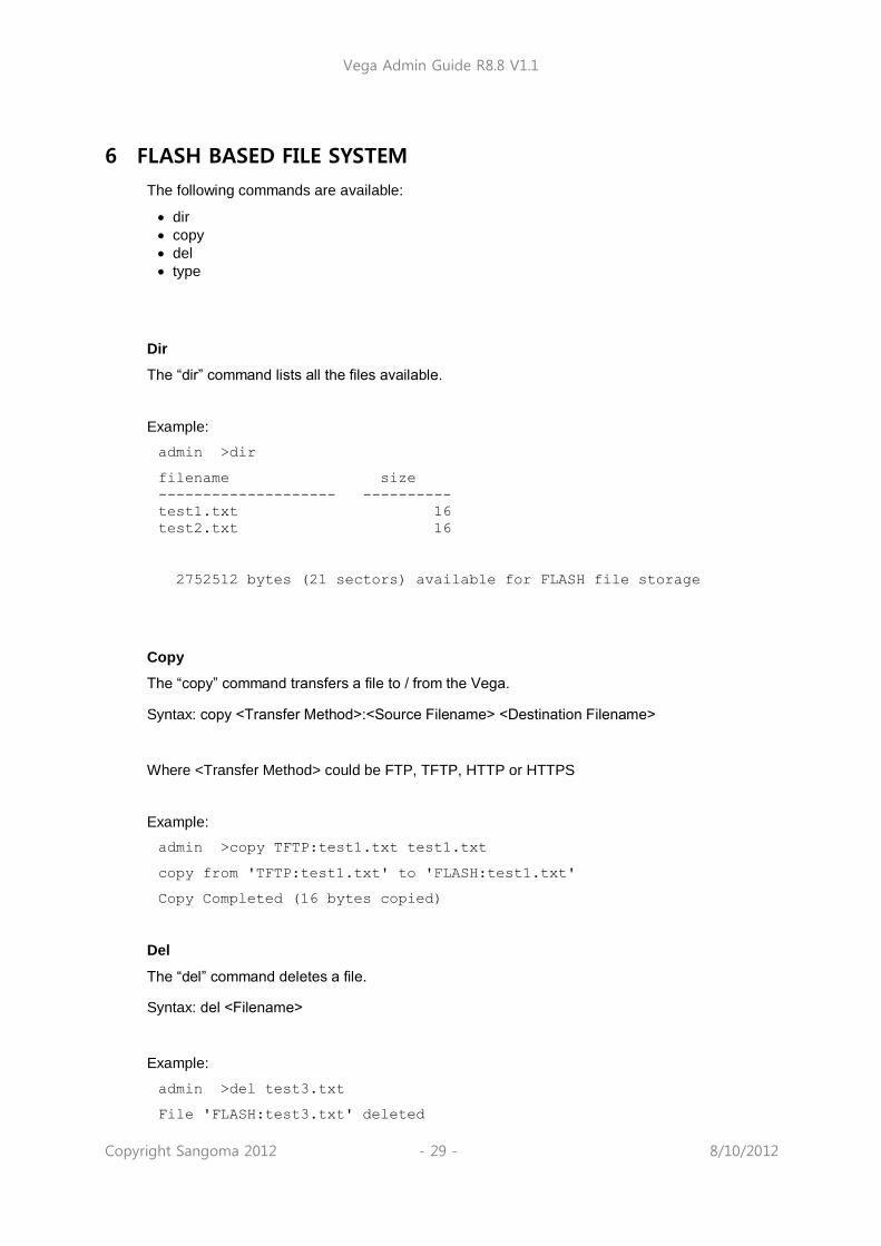
Vega Admin Guide R8.8 V1.1
Copyright Sangoma 2012 - 29 - 8/10/2012
6 FLASH BASED FILE SYSTEM
The following commands are available:
dir
copy
del
type
Dir
The “dir” command lists all the files available.
Example:
admin >dir
filename size
-------------------- ----------
test1.txt 16
test2.txt 16
2752512 bytes (21 sectors) available for FLASH file storage
Copy
The “copy” command transfers a file to / from the Vega.
Syntax: copy <Transfer Method>:<Source Filename> <Destination Filename>
Where <Transfer Method> could be FTP, TFTP, HTTP or HTTPS
Example:
admin >copy TFTP:test1.txt test1.txt
copy from 'TFTP:test1.txt' to 'FLASH:test1.txt'
Copy Completed (16 bytes copied)
Del
The “del” command deletes a file.
Syntax: del <Filename>
Example:
admin >del test3.txt
File 'FLASH:test3.txt' deleted

Vega Admin Guide R8.8 V1.1
Copyright Sangoma 2012 - 30 - 8/10/2012
Type
The “type” command displays the contents of the file.
Syntax: type <Filename> [params]
Where: params can be -nx where x is the maximum number of bytes in the output
Examples:
admin >type test1.txt
Test
Test
1234
admin >type test1.txt –n4
Test
File System Initialisation
Minimum Boot code version 3.00 must be running on the Vega gateway where file based dial plans will be used. If a boot code upgrade is required, after it is complete the FLASH file system must be initialised. This is performed by accessing the boot menu (via 9600bps serial connection) – see documentation on www.vegaassist.com for more information on accessing boot menu.
Once the boot menu is accessed two steps are required:
1. Access the extended command set using the “^” command. 2. Initialise the filesystem using the “C” command.
Example:
VegaStream Boot Menu Version 3.00
---------- ---- ---- ------------
1) Download Boot Image (SRec)
2) Download Firmware Image (SRec) (115K2 Baud recommended)
3) Config Clear
6) Switch Boot Partition
D) Duplicate FLASH
F) Set Flow Control (currently Hardware)
Z) Set speed high (115200 Baud)
E) Exit BOOT and Run Firmware

Vega Admin Guide R8.8 V1.1
Copyright Sangoma 2012 - 31 - 8/10/2012
?^
VegaStream Boot Menu Version 3.00
---------- ---- ---- ------------
1) Download Boot Image (SRec)
2) Download Firmware Image (SRec) (115K2 Baud recommended)
3) Config Clear
6) Switch Boot Partition
D) Duplicate FLASH
F) Set Flow Control (currently Hardware)
4) Download Firmware Image (Binary) (115K2 Baud recommended)
5) Download Boot Image (Binary)
7) DSP Memory Test
8) PHY Registers Read/Write
C) Initialise FLASH File System
R) Continous RAM test
X) Verify File System
Z) Set speed high (115200 Baud)
E) Exit BOOT and Run Firmware
?C
WARNING - Converting FileSystem, Please Wait
FAT#1 position 0x00020000, FAT#2 position 0x00C00000
File 'BOOT' at 0x00400000, size 0x00020000
File 'CONFIG' at 0x00420000, size 0x00020000
File 'IMAGE1' at 0x00840000, size 0x00640000
File 'IMAGE2' at 0x00040000, size 0x00640000
Conversion Completed

Vega Admin Guide R8.8 V1.1
Copyright Sangoma 2012 - 32 - 8/10/2012
7 SYSTEM CONFIGURATION DATABASE
7.1 Configuration Storage and Layout
The system configuration database contains all the Vega configuration parameters; it is held within the Vega gateway memory. The configuration is broken down into a number of sections. Each section has a name, as do all parameters within each section. There are four versions of the configuration within the unit:
1) Factory configuration – in program memory Contains factory defaults that are specific to a particular firmware version.
2) Saved configuration Contains the last saved user configuration and is changed using the SAVE and FACTORY RESET commands only.
3) User configuration At boot time this memory is loaded with the last saved configuration entries. This area can be viewed and changed directly using the command line interface commands CP, SHOW, SET, NEW, DELETE, FACTORY RESET, and GET commands, also indirectly using the PC web browser.
4) Runtime configuration At boot time (power on or after a „reboot system‟) this memory is loaded with the last saved configuration entries. The Vega runtime code uses these configuration values to define how the unit operates. The show plan command allows vision of the runtime dial plan entries. Certain parameters – like the dial plan - can be updated from values stored in the user configuration memory using the APPLY command.
Web browser configuration
PUT TPUT
User
Configuration
Memory
Saved
Configuration
Memory
Program
Memory
Runtime
Configuration
Memory
PC
Web
browser
PC memory Vega RAM memory Vega FLASH memory
APPLY
- operates only
on specific
variables …
see table
SUBMIT
SHOW …
CLI commands
… SET
SAVE
REBOOT SYSTEM
REBOOT
SYSTEM
FACTORY RESET
FACTORY
RESET
SHOW PLAN
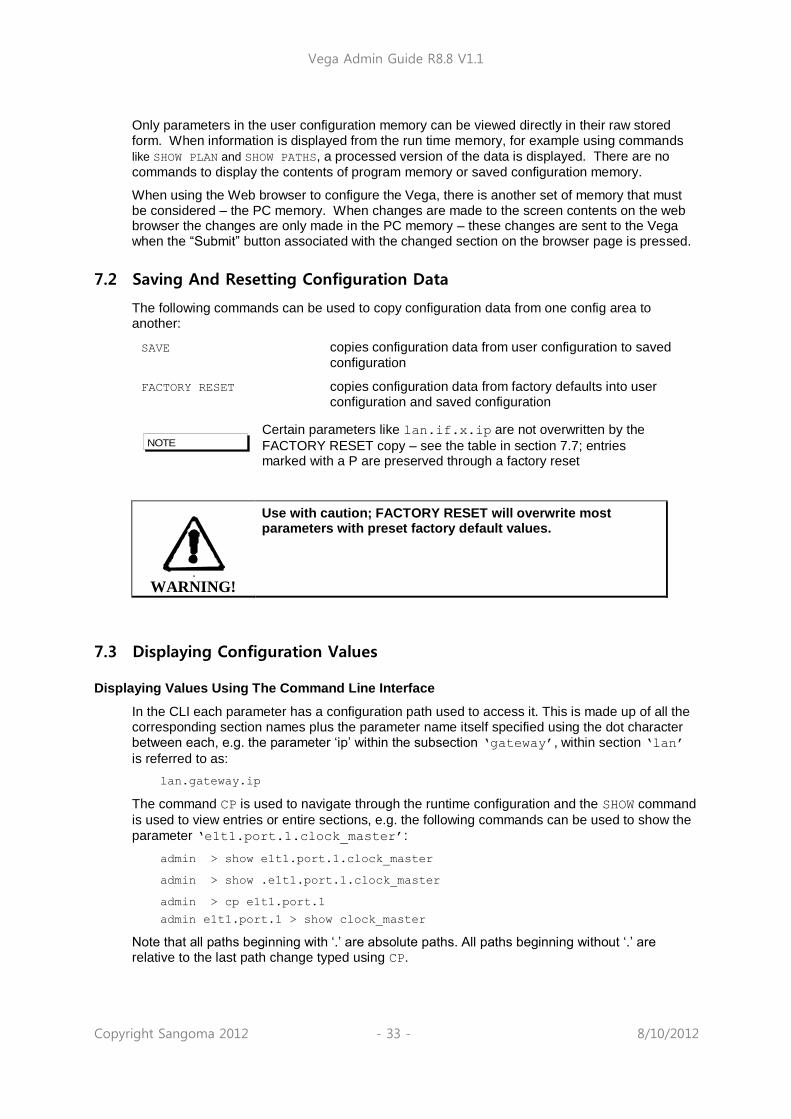
Vega Admin Guide R8.8 V1.1
Copyright Sangoma 2012 - 33 - 8/10/2012
Only parameters in the user configuration memory can be viewed directly in their raw stored form. When information is displayed from the run time memory, for example using commands
like SHOW PLAN and SHOW PATHS, a processed version of the data is displayed. There are no
commands to display the contents of program memory or saved configuration memory.
When using the Web browser to configure the Vega, there is another set of memory that must be considered – the PC memory. When changes are made to the screen contents on the web browser the changes are only made in the PC memory – these changes are sent to the Vega when the “Submit” button associated with the changed section on the browser page is pressed.
7.2 Saving And Resetting Configuration Data
The following commands can be used to copy configuration data from one config area to another:
SAVE copies configuration data from user configuration to saved
configuration
FACTORY RESET copies configuration data from factory defaults into user configuration and saved configuration
Certain parameters like lan.if.x.ip are not overwritten by the
FACTORY RESET copy – see the table in section 7.7; entries marked with a P are preserved through a factory reset
WARNING!
Use with caution; FACTORY RESET will overwrite most parameters with preset factory default values.
7.3 Displaying Configuration Values
Displaying Values Using The Command Line Interface
In the CLI each parameter has a configuration path used to access it. This is made up of all the corresponding section names plus the parameter name itself specified using the dot character between each, e.g. the parameter „ip‟ within the subsection „gateway‟, within section „lan‟
is referred to as:
lan.gateway.ip
The command CP is used to navigate through the runtime configuration and the SHOW command
is used to view entries or entire sections, e.g. the following commands can be used to show the
parameter „e1t1.port.1.clock_master‟:
admin > show e1t1.port.1.clock_master
admin > show .e1t1.port.1.clock_master
admin > cp e1t1.port.1
admin e1t1.port.1 > show clock_master
Note that all paths beginning with „.‟ are absolute paths. All paths beginning without „.‟ are relative to the last path change typed using CP.
NOTE

Vega Admin Guide R8.8 V1.1
Copyright Sangoma 2012 - 34 - 8/10/2012
7.3.1.1 Show
All sections displayed using SHOW or SHOW <section> will display the section and any sub-
sections below that section. If the section name is followed by a „.‟ character then only that section will be displayed. For example, to display all LAN parameters:
admin >show lan
[lan]
dns=0.0.0.0
gateway=10.0.0.1
ip=200.100.50.25
name=Vega100
ntp=0.0.0.0
ntp_local_offset=0000
ntp_poll_interval=0
subnet=255.255.255.0
tftp=0.0.0.0
use_dhcp=0
[lan.localDNS.1]
ip=127.0.0.1
name=loopback
[lan.phy]
full_duplex=0
10baset=1
100basetx=1
And to display only parameters in the top LAN section:
admin >show lan.
[lan]
dns=0.0.0.0
gateway=10.0.0.1
ip=200.100.50.25
name=Vega100
ntp=0.0.0.0
ntp_local_offset=0000
ntp_poll_interval=0
subnet=255.255.255.0
tftp=0.0.0.0
use_dhcp=0
7.3.1.2 Show status
SHOW STATUS or SHOW <section> STATUS will display a list of parameters, within the
section and any sub-sections below that section, which are different to their default or saved values. It also indicates against each entry whether it is different from the factory default value and/or the saved value.
SHOW ALL STATUS performs a SHOW STATUS followed by SHOW _advanced STATUS, so
the output consists of 2 sets of results.
For example:
admin >show lan status
Configuration changes:

Vega Admin Guide R8.8 V1.1
Copyright Sangoma 2012 - 35 - 8/10/2012
Key: CU: Changed from factory and unsaved.
C-: Changed from factory and saved.
-U: Not changed but unsaved.
[lan]
CU dns=136.170.208.4
-U ftp=0.0.0.0
CU gateway=136.170.208.1
CU ip=136.170.209.248
CU ntp=136.170.144.18
CU subnet=255.255.254.0
CU tftp=136.170.209.228
CU use_dhcp=0
[lan.dhcp]
-U get_gateway=1
[lan.localDNS.2]
C- name=new_host
[lan.localDNS.3]
C- ip=0.0.0.0
C- name=new_host
Total changed: 10 Unsaved: 9
7.3.1.3 Show changes
SHOW CHANGES or SHOW <section> CHANGES will display a list of parameters, within the
section and any sub-sections below that section, which are different to their default or saved values. It also indicates against each entry whether it is different from the factory default value and/or the saved value; factory and/or saved values are displayed where they are different.
SHOW ALL CHANGES performs a SHOW CHANGES followed by SHOW _advanced CHANGES,
so the output consists of 2 sets of results.
For example:
admin >show lan changes
Configuration changes:
Key: CU: Changed from factory and unsaved.
C-: Changed from factory and saved.
-U: Not changed but unsaved.
[lan]
CU dns=136.170.208.4
*factory=0.0.0.0
-U ftp=0.0.0.0
*saved=136.170.208.123
CU gateway=136.170.208.1
*factory=0.0.0.0
*saved=0.0.0.0
CU ip=136.170.209.248
*factory=0.0.0.0
*saved=136.170.208.204
CU ntp=136.170.144.18
*factory=0.0.0.0
CU subnet=255.255.254.0
*factory=255.255.255.0
CU tftp=136.170.209.228
*factory=0.0.0.0

Vega Admin Guide R8.8 V1.1
Copyright Sangoma 2012 - 36 - 8/10/2012
*saved=136.170.209.248
CU use_dhcp=0
*factory=1
*saved=1
[lan.dhcp]
-U get_gateway=1
*saved=0
[lan.localDNS.2]
C- ip=0.0.0.0
*factory=New entry
C- name=new_host
*factory=New entry
[lan.localDNS.3]
C- ip=0.0.0.0
*factory=New entry
C- name=new_host
*factory=New entry
Total changed: 11 Unsaved: 9
7.3.1.4 Show verbose
SHOW VERBOSE or SHOW <section> VERBOSE will display a list of all parameters within the
section and any sub-sections below that section. For those that are different to their default or saved values the listing will indicate which value they are different to, and will list the value of the factory default and/or saved value, whichever is/are different.
SHOW ALL VERBOSE performs a SHOW VERBOSE followed by SHOW _advanced VERBOSE,
so the output consists of 2 sets of results.
For example:
admin >show lan. verbose
Configuration changes:
Key: CU: Changed from factory and unsaved.
C-: Changed from factory and saved.
-U: Not changed but unsaved.
[lan]
CU dns=136.170.208.4
*factory=0.0.0.0
-U ftp=0.0.0.0
*saved=136.170.208.123
CU gateway=136.170.208.1
*factory=0.0.0.0
*saved=0.0.0.0
CU ip=136.170.209.248
*factory=0.0.0.0
*saved=136.170.208.204
name=Vega100T1E1
CU ntp=136.170.144.18
*factory=0.0.0.0
ntp_local_offset=0000
ntp_poll_interval=0
CU subnet=255.255.254.0
*factory=255.255.255.0
CU tftp=136.170.209.228
*factory=0.0.0.0
*saved=136.170.209.248

Vega Admin Guide R8.8 V1.1
Copyright Sangoma 2012 - 37 - 8/10/2012
CU use_dhcp=0
*factory=1
*saved=1
Total changed: 11 Unsaved: 9

Vega Admin Guide R8.8 V1.1
Copyright Sangoma 2012 - 38 - 8/10/2012
7.4 Changing Configuration Values
Changing Configuration Values Using The Web Browser
In the web browser, configuration values have been grouped together into appropriate pages – values are changed by entering the new value into the appropriate text box, selecting the required value using a combo selector, or selecting the right value using a radio button selector.
Once the desired value has been specified press the “Submit” button to send the information to the user configuration memory in the Vega.
Changing Configuration Values Using The Command Line Interface
The commands SET, NEW, PURGE, DELETE , GET and FACTORY RESET can be used to change the user configuration.
SET changes an existing parameter value.
admin > set path.parameter=value
Multiple parameters can be set using the same command, separating entries with spaces,
admin > set path.parameter=value path.parameter2=value2 etc.
To get help on the range of possible values to use for a specific parameter type:
SET <path.parameter>=?
e.g. to set the host name:
admin >set lan.name=test
[lan].name=test
e.g. to set the host name and the tftp address
admin >set lan.name=test lan.tftp=192.168.1.108
[lan].name=test
[lan].tftp=192.168.1.108
e.g. to retrieve help on the syntax
admin >set lan.name=?
entry : lan.name
expecting: string of between 1 and 31 characters
If you have a number of different parameters to change in a specific path, or a long path to type in, instead of typing in the full path each time use cp path to get to the desired place then use the sub path
from here to the parameter, or if the Vega is now in the parameter’s
path just use set parameter=value
e.g.: cp.lan
set name=test ; configures lan.name
7.5 Manipulating List Sections
A list section contains 1 or more numbered subsections. Each subsection contains the same set of configurable parameters. Lists are used where either i) a variable number of sets of
entries need to be defined (e.g. lan.localDNS entries) or ii) a number of sets of parameters
NOTE

Vega Admin Guide R8.8 V1.1
Copyright Sangoma 2012 - 39 - 8/10/2012
can be configured and the Vega selects the appropriate set through configuration of another parameter (e.g. serviceprofile and qos_profile).
Manipulating List Sections using the web browser
Where required the “Add” and “Delete” buttons are provided to add or delete entries from lists. When add is used, the list section added is initialised to default values which can then be overwritten to the desired values.
Manipulating List sections using the Command Line Interface
The command NEW <path> (or the command NEW from within the list structure) adds a new
numbered record to the list section, initialising it with default values. The command SET can
then be used to override these default values with new ones. E.g. to check the lan.localDNS table, then add a new entry to the LAN localDNS table and configure its 2 parameters using a
single SET command:
admin >show lan.localDNS
[lan.localDNS.1]
ip=127.0.0.1
name=loopback
admin >new lan.localDNS
admin lan.localDNS.2 >show
[lan.localDNS.2]
ip=0.0.0.0
name=new_host
admin lan.localDNS.2 >set ip=1.2.3.4 name=test
[lan.localDNS.2].ip=1.2.3.4
[lan.localDNS.2].name=test
DELETE removes either the last record from a list section, or the specified record, e.g. to remove the last entry:
admin lan.localDNS.2 > cp .
admin >delete lan.localDNS 2
Delete OK
admin >show lan.localDNS
[lan.localDNS.1]
ip=127.0.0.1
name=loopback
PURGE removes all records in a particular list section, leaving just the first record (which must always be there). This can be used to „clean‟ sections to a known state prior to restoring data.
7.6 Activating Configuration Changes
Changes to the configuration parameters are activated (ie are used by the running system) at different times depending on the type of parameter. Each entry falls into one of the following categories:
S/R Effective after SAVE and REBOOT SYSTEM only
APPLY Effective after APPLY
CALL Effective on next call
IMM Effective immediately
LOG Effective after log out/log in

Vega Admin Guide R8.8 V1.1
Copyright Sangoma 2012 - 40 - 8/10/2012
1) On the web browser interface the “Submit” or “Apply”
button must be pressed first to send the data to the Vega.
2) Entries activated after APPLY, CALL, IMM or LOG are not automatically saved in the non-volatile portion of the database. The SAVE command must still be used.
The activation category that each parameter is associated with has, where possible, been chosen according to the parameter‟s use; for example, DSP parameters are effective on next CALL so you can hear the difference when making small changes.
Typically major changes are only effective after a reboot.
7.7 Configuration Entries
The following table lists the configuration entries by section. Some of the section headers and parameters are hyperlinked – selecting them will take you to a section discussing the use of these parameters.
The activate column denotes when the change will take effect (for definition see chapter 7.6).
Key to symbols:
Activate field: P = Preserved through a factory reset
NOTE

Vega Admin Guide R8.8 V1.1
Copyright Sangoma 2012 - 41 - 8/10/2012
FX
S / F
XO
BR
I
E1/T
1
H 3 2 3
S I P
Section/Parameter Activate Range Comments
[bri]
topology=s0 S/R s0 Network topology or card type
[bri.port.1]
bus_master_priority=1 APPLY 0 to 4 Preference level for synchronising the
internal clock to this port, 1 = highest
priority, 4 = lowest, 0 = don‟t use this port
crossover=0 APPLY 0 or 1 0 = Maintain standard connector pin-out
depending on NT/TE setting.
1 = Use crossover pin-out.
enable=on APPLY On / Off / 0
/ 1
0 / off = Do not enable this link
1 / on = Enable this link
framing=s_t S/R s_t/auto Framing, auto = s_t
line_encoding=azi S/R azi/ auto Line encoging, auto=azi3
line_type=pmp pmp or pp Line type can be either Point-to-Multipoint or
Point-to-Point
lyr1=auto APPLY G711Alaw64k/
g711Ulaw64k/
auto
A-law or u-law companding
(G.711Alaw64k/G.711Ulaw64k) on the BRI LINK
auto=g711Alaw64k
network=etsi S/R etsi Network type.
nt=0 APPLY 0 or 1 0=TE, 1=NT;
nt_phantom_power=0 APPLY 0 or 1 1= Provide power to BRI interfaces which are
configured as NT (designed to power ISDN
phone handsets, and sometimes used as a
connection signal to ISDN PBXs)
restart_l2_after_disc=0 APPLY 0 = re-establish layer 2 only if layer 1 is
also down.
1 = force re-establishment of layer 2 if a
layer 2 disconnect occurs.
tdm_profile=1 APPLY 1 – 10 Selects the TDM profile to use within the
media section. Defines the echo, idle noise
and silence threshold to be used for this
port. See the media section for more
details.
tei=0 APPLY 0 to 63 For BRI, if the line is configured as Point-
to-Point, tei defines the Terminal Endpoint
Identifier – a static value of 0 to 63. Both
ends must have the same value configured.
In BRI Point-to-Multi-Point this figure is
not configurable but is negotiated (and will
have a value in the range 64 to 126)
3 azi is the proper name for BRI line encoding on an S/T interface (hdb3 is the encoding used on
the U interface)

Vega Admin Guide R8.8 V1.1
Copyright Sangoma 2012 - 42 - 8/10/2012
FX
S / F
XO
BR
I
E1/T
1
H 3 2 3
S I P
Section/Parameter Activate Range Comments
[bri.port.1.group.1]
alloc_chan=default S/R default/
linear_up/
linear_down/
round_robin
Type of channel allocation strategy used
(default = linear up if BRI LINK is NT and
Linear down if BRI LINK is TE)
dn=* S/R Length<32 TE trunk: dn specifies the incoming telephone
number that the trunk will respond to
first_chan=1 S/R 1-2 First B-chan for this group
interface=0301 S/R Length<32 Interface ID for this BRI LINK
0301 to 0308
last_chan=2 S/R 1-2 Last B-chan for this group
tunnel_IEs_only=1 0 or 1 Tunnel specific information elements. IEs to
tunnel are defined in
_advanced.isdn.IEs_to_tunnel.
N.B. Enable this parameter for both source
AND destination trunks (for ISDN to ISDN
tunnelling)
See table in section 0 “Tunnelling full
signalling messages and IEs in ISDN (ETSI,
ATT, DMS, DMS-M1, NI, VN 3/4) and QSIG” for
details of interactions of various parameters
with tunnel_IEs_only.
tunnel_mode=on-demand S/R off/on-demand Enable tunnelling, for full details see the
table in section 0 “Tunnelling full signalling
messages and IEs in ISDN (ETSI, ATT, DMS, DMS-
M1, NI, VN 3/4) and QSIG”
[bri.port.1.isdn] ISDN and QSIG config
call_appearance=1 -254 .. 254 Configuration for US BRI (… when
network=att_TE) - adds layer 3 Call
appearance IE.
0: disabled
1 .. 254: Base value to use for the call
appearance (uses a linear_up fill algorith on
a per port basis)
-1 .. –254: Use the positive value of this
number for all outgoing calls on this BRI
LINK – i.e. fixed call appearance value for
all calls on this BRI LINK
chanid_excl=0 APPLY 0 or 1 Affects the 'preferred/exclusive' bit in the
ISDN B-Channel Id Info Element of outbound
ISDN calls
0 = 'preferred‟
1 = „exclusive‟ … far end to drop call if
this B-channel cannot be used
dtmf_dial_digit=# APPLY 0 to 9, *, #,
A to D, Z
DTMF dial termination character – the DTMF
character that indicates that the dialled
number is complete (overrides
dtmf_dial_timeout) forcing the received
number to be passed to the dial plan router
(set to Z to disable this function)
dtmf_dial_timeout=5 APPLY 1-999 Time after last dialled digit is received
that dialled number is forwarded to the dial
plan router (in seconds)
999 = no timeout used

Vega Admin Guide R8.8 V1.1
Copyright Sangoma 2012 - 43 - 8/10/2012
FX
S / F
XO
BR
I
E1/T
1
H 3 2 3
S I P
Section/Parameter Activate Range Comments
end_to_end_call_proceeding=0 APPLY 0,1 0 = Disabled
1 = Enabled, For ISDN to ISDN calls Vega will
wait for incoming call proceeding message
before transmitting call proceeding message
on the originating ISDN link.
incoming_cause_mapping_index
=0
APPLY Index Cause code mapping entry to use from
_advanced.incoming_cause_mapping to map
incoming cause codes on this BRI link
outgoing_cause_mapping_index
=0
APPLY Index Cause code mapping entry to use from
_advanced.outgoing_cause_mapping to map
outgoing cause codes on this BRI link
U
S
registered_dn=5551000 Configuration for US BRI (… when
network=att_TE)
setup_mapping_index=0 APPLY Index Mapping entry to use from
_advanced.setup_mapping for this BRI LINK
U
S
spid1=1001 Configuration for US BRI (… when
network=att_TE)
U
S
spid2=1002 Configuration for US BRI (… when
network=att_TE)
wait_for_calling_name_time=0
0 .. 10000 In some (particularly T1) systems, the
caller‟s display name may be sent as a
facility message after the initial set up.
If the Vega is to use this in the outgoing
VoIP call the Vega must wait for the facility
message to arrive. This parameter tells the
Vega how long to wait (in ms).
[call_control.timers.1] Currently only 1 set, set 1 supported
T301_timeout=90 S/R 0 to 1000 Ringing timeout in seconds
T301_cause=19 S/R 0 to 127 Q.850 cause code to use on Ring Tone No Reply
timeout (see IN 18 for cause code details)
[cron.entry.1]
enable=1 Apply 0 or 1 0 = disable
1 = enable
script=blank Apply Alpha numeric
string 1..64
chars
Command file to pick up and execute
(scheduled autoexec)
when=never Apply Alpha numeric
string 1..80
chars
Never = do not execute ever
Space separated values for “minute" "hour"
"day of month" "month" "day of
week”
Where:
* Matches every minute, hour etc.
n One specific minute/hour/etc.
n,m A comma-delimited list of matching
minutes/hours/etc.
n-m An inclusive range of
minutes/hours/etc.
/n "every n intervals" used to modify
a range
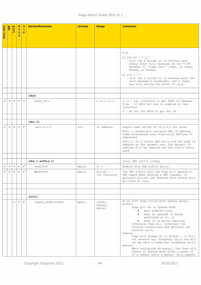
Vega Admin Guide R8.8 V1.1
Copyright Sangoma 2012 - 44 - 8/10/2012
FX
S / F
XO
BR
I
E1/T
1
H 3 2 3
S I P
Section/Parameter Activate Range Comments
e.g.
12 23-7/2 * * 1,7
will run a script at 12 minutes past
every other hour (because of the "/2")
between 23 (11pm) and 7 (7am), on every
Monday or Sunday.
12 0-6 * 7 *
will run a script at 12 minutes past the
hour between 0 (midnight) and 6 (6am),
but only during the month of July.
[dns]
dhcp_if=1 0 or 1 or 2 1..2 - Lan interface to get DHCP IP address
from – if DHCP for dns is enabled in that
interface
0 – do not use DHCP to get dns IP
[dns.1]
ip=0.0.0.0 S/R IP address Domain name server IP (0.0.0.0 for none)
Note 1: Dynamicaly assigned DNS IP address
takes precedence over statically defined IP
addresses
Note 2: If a static DNS entry has the same IP
address as the dynamic one, the dynamic IP
address will be igmnord and the static entry
used
[dns.1.suffix.1] Local DNS suffix lookup
enable=0 Apply 0, 1 Enable this DNS suffix entry.
name=com Apply String 1 –
128 character
The DNS suffix that the Vega will append to
DNS names when sending a DNS request. If
multiple entries are defined each suffix will
be tried in turn.
[e1t1]
bypass_mode=normal Apply normal,
bypass,
manual
On an E1T1 Vega fitted with ByPass ports:
normal:
Vega will be in ByPass mode
when powered down,
when an upgrade is being
performed on it, or
when it is being rebooted.
Otherwise Vega will terminate the
telecom connections and generate and
receive calls.
bypass:
Vega will always be in ByPass – it will
not receive any telephony calls and will
not be able to make any telephony calls.
manual:
When configured as manual, the Vega will
remain in ByPass mode after a power on
or a reboot until a manual „e1t1 bypass

Vega Admin Guide R8.8 V1.1
Copyright Sangoma 2012 - 45 - 8/10/2012
FX
S / F
XO
BR
I
E1/T
1
H 3 2 3
S I P
Section/Parameter Activate Range Comments
off‟ command is executed.
For further details, see IN_44-
Vega_400_ByPass_relays on the technical
documents page of www.wiki.sangoma.com/vega
topology=e1 S/R e1/t1 Network topology or card type
[e1t1.port.1]
bus_master_priority=1 APPLY 0 to 4 Preference level for synchronising the
internal clock to this port, 1 = highest
priority, 4 = lowest, 0 = don‟t use this port
clock_master=0 S/R 0 or 1 0 for no clock generation, 1 for clock
generation
crossover=0 APPLY 0 or 1 0 = Maintain standard connector pin-out
depending on NT/TE setting.
1 = Use crossover pin-out.
disc_on_user_suspend=0 APPLY 0 or 1 0: normal operation
1: on receipt of an incoming ISDN NOTIFY
message containing a NOTIFY INDICATOR = USER
SUSPEND the Vega will initiate call
disconnection. This gets round the problem
of the 90 second cleardown timer where a
called party gets re-connected to the calling
party again if they pick up the phone within
90 seconds and the calling party has not
cleared down at their end.
enable=on APPLY 0/1/off/on/ti
ming
Trunk enabled
0, off: trunk is disabled
1, on: trunk is enabled
timing: trunk is used for timing (Vega won‟t
bring up layer 2/3). If configured as NT,
the Vega will generate clock signal on this
trunk; if configured as TE, the Vega will
treat an incoming clock as a valid clock to
synchronise to.
E
1
e1_rx_short_haul=1 S/R 0 or 1 0 = long haul (>6dB attenuation in line)
1 = short haul (<=6dB attenuation in line)
framing=auto S/R esf/sf/crc4/
pcm30/auto
T1: Extended Super frame / Super frame (SF =
D4); auto=esf
E1: CRC4 / PCM30 (PCM30 = no CRC4); auto=crc4
line_encoding=auto S/R 2b1q/b8zs/ami
/hdb3/ auto
Line encoding type used
T1: b8zs / ami; auto=b8zs
E1: hdb3; auto=hdb3
lyr1=auto APPLY G711Alaw64k/
g711Ulaw64k/
auto
A-law or u-law companding
(G.711Alaw64k/G.711Ulaw64k) on the E1T1
auto=g711Alaw64k
network=auto S/R auto
att
dms
ni
qsig
cas-rbs
dms_m1
vn
cas-r2
cas_pw
arinc
Network type.
“auto” configures “etsi” for E1 systems and
“dms” for T1 systems.

Vega Admin Guide R8.8 V1.1
Copyright Sangoma 2012 - 46 - 8/10/2012
FX
S / F
XO
BR
I
E1/T
1
H 3 2 3
S I P
Section/Parameter Activate Range Comments
1tr6
nt=0 APPLY 0 or 1 For ISDN: 0=TE, 1=NT;
For QSIG: 0= Slave or B-side, 1=Master or A-
side
For RBS (CAS): - not used
tdm_profile=1 APPLY 1 – 10 Selects the TDM profile to use within the
media section. Defines the echo, idle noise
and silence threshold to be used for this
port. See the media section for more
details.
T
1
t1_tx_equalization
=sh220_330
lhlbo0
lhlbo7_5
lhlbo15
lhlbo22_5
sh0_110
sh110_220
sh220_330
sh330_440
sh440_550
sh550_660
Specify the transmit equalization (for T1
interfaces only).
[e1t1.port.1.group.1]
alloc_chan=default S/R default/
linear_up/
linear_down/
round_robin
Type of channel allocation strategy used
(default = linear up if E1T1 is NT and Linear
down if E1T1 is TE)
dn=* S/R Length<32 Vega E1T1: unused for Caller ID or incoming
number detection.
first_chan=1 S/R E1: 1-30
T1 PRI: 1-23
T1 CAS: 1-24
First B-chan for this group
interface=0401 S/R Length<32 Interface ID for this E1T1
0401 to 0404
last_chan=auto S/R E1: 1..30,
auto
T1 PRI:
1..23, auto
T1 CAS:
1..24, auto
Last B-chan for this group
Note. If the E1T1 is connected to a partial
T1 or E1 ensure that last_chan is configured
appropriately, otherwise calls may be placed
to non existent channels
pw_answer_only=0 APPLY 0 or 1 0: Vega will start sending SIP INVITEs to
initiate the trunk as soon as the E1T1 link
becomes active.
1: Vega will wait for SIP INVITEs from other
endpoint.
pw_protocol=pw_mrd APPLY pw_mrd
pw_pwa
pw_em
pw_plar
pw_fxs
pw_fxo
If cas_pw is selected as the network type for
the E1T1, defines the private wire signalling
that will be used for this group.

Vega Admin Guide R8.8 V1.1
Copyright Sangoma 2012 - 47 - 8/10/2012
FX
S / F
XO
BR
I
E1/T
1
H 3 2 3
S I P
Section/Parameter Activate Range Comments
pw_tos
tunnel_IEs_only=1 0 or 1 Tunnel specific information elements. IEs to
tunnel are defined in
_advanced.isdn.IEs_to_tunnel.
N.B. Enable this parameter for both source
AND destination trunks (for ISDN to ISDN
tunnelling)
See table in section 0 “Tunnelling full
signalling messages and IEs in ISDN (ETSI,
ATT, DMS, DMS-M1, NI, VN 3/4) and QSIG” for
details of interactions of various parameters
with tunnel_IEs_only.
tunnel_mode=on-demand S/R off/on-demand Enable tunnelling, for full details see the
table in section 0 “Tunnelling full signalling
messages and IEs in ISDN (ETSI, ATT, DMS, DMS-
M1, NI, VN 3/4) and QSIG”
[e1t1.port.1.isdn] ISDN and QSIG config
chanid_excl=0 APPLY 0 or 1 Affects the 'preferred/exclusive' bit in the
ISDN B-Channel Id Info Element of outbound
ISDN calls
0 = 'preferred‟
1 = „exclusive‟ … far end to drop call if
this B-channel cannot be used
dtmf_dial_digit=# APPLY 0 to 9, *, #,
A to D, Z
DTMF dial termination character – the DTMF
character that indicates that the dialled
number is complete (overrides
dtmf_dial_timeout) forcing the received
number to be passed to the dial plan router
(set to Z to disable this function)
dtmf_dial_timeout=5 APPLY 1-999 Time after last dialled digit is received
that dialled number is forwarded to the dial
plan router (in seconds)
999 = no timeout used
end_to_end_call_proceeding=0 APPLY 0,1 0 = Disabled
1 = Enabled, For ISDN to ISDN calls Vega will
wait for incoming call proceeding message
before transmitting call proceeding message
on the originating ISDN link.
incoming_cause_mapping_index
=0
APPLY Index Cause code mapping entry to use from
_advanced.incoming_cause_mapping to map
incoming cause codes on this E1T1
mwi_enable=0 APPLY 0,1 0 = Disabled
1 = Enabled, Enable reception or generation
of message waiting indicator. Can be used to
map SIP MWI to ISDN devices.
outgoing_cause_mapping_index
=0
APPLY Index Cause code mapping entry to use from
_advanced.outgoing_cause_mapping to map
outgoing cause codes on this E1T1
setup_mapping_index=0 APPLY Index Mapping entry to use from
_advanced.setup_mapping for this E1T1
untromboning_enable=0 APPLY 0,1 0 = Disabled
1 = Enabled, Allow the Vega to untrombone (or
optimise) bearer channels when SIP indicates
this can be done.
0 to 10000 In some (particularly T1) systems, the

Vega Admin Guide R8.8 V1.1
Copyright Sangoma 2012 - 48 - 8/10/2012
FX
S / F
XO
BR
I
E1/T
1
H 3 2 3
S I P
Section/Parameter Activate Range Comments
wait_for_calling_name_time=0 caller‟s display name may be sent as a
facility message after the initial set up.
If the Vega is to use this in the outgoing
VoIP call the Vega must wait for the facility
message to arrive. This parameter tells the
Vega how long to wait (in ms).
[e1t1.port.1.rbs] T1 CAS – RBS configuration
digit_dial_timeout=2 APPLY 1 .. 1000 Time after last dialled digit is received
that DNIS / ANI are treated as complete –
time is in seconds
(Initial digit timeout = 10 times this value)
fsk_time_type=DST APPLY base or DST Base: use base local time for Caller ID time
DST: use Daylight Saving Time for Caller ID
time
fsk_tone_delay=2000 1..20000 Milliseconds delay after seize before sending
the FSK caller ID (if enabled in
fsk_tone_format)
fsk_tone_format=off off,
gr30-sdmf,
gr30-mdmf
When using a Vega E1T1 with a CAS channel bank
that does not support caller ID, the Vega can
generate the FSK tones. This parameter
enables the tone generation and defines the
format of the FSK.
info=dtmf APPLY dtmf or mf DTMF tones or MF tones can be used to send
DNIS / ANI
progress_tones_present=1 0 or 1 0: no progress tones indicated in progress
message sent from CAS to router after dialling
is complete
1: progress tones indicated in progress
message sent from CAS to router after dialling
is complete
rx_dial_format=. APPLY . = default
format
or
Format of
DNIS/ANI
Define the format of the ANI/ DNIS in the CAS
signalling – for incoming CAS calls (received
ANI/DNIS).
o = ANI,
n = DNIS
DTMF can use the separator characters: 0-9,
A-D, *,#, ~
MF can use the separator characters: 0-9, K,
S, ~
signal=em_wink S/R em_wink,
loopstart,
gndstart, or
fgd
CAS RBS signalling type (fgd = em_wink
supporting feture group D – em_wink supports
feature group B)
tone_delay=50 APPLY 1 to 1000 Delay after the remote end has sent
acknowledgement wink (in E&M wink start
signalling) before starting to play the
outbound DNIS and ANI tones (in milliseconds)

Vega Admin Guide R8.8 V1.1
Copyright Sangoma 2012 - 49 - 8/10/2012
FX
S / F
XO
BR
I
E1/T
1
H 3 2 3
S I P
Section/Parameter Activate Range Comments
tx_dial_format=. APPLY . = default
format
or
Format of
DNIS/ANI
Define the format of the ANI/ DNIS in the CAS
signalling – for outgoing CAS calls
(transmitted ANI/DNIS).
o = ANI,
n = DNIS
DTMF can use the separator characters: 0-9,
A-D, *,#, ~
MF can use the separator characters: 0-9, K,
S, ~

Vega Admin Guide R8.8 V1.1
Copyright Sangoma 2012 - 50 - 8/10/2012
FX
S / F
XO
BR
I
E1/T
1
H 3 2 3
S I P
Section/Parameter Activate Range Comments
[e1t1.port.1.r2]
category=sub_wo_pri_nl sub_w_pri_nl/
sub_wo_pri_nl
/
mnt_equip_nl/
data_trns_nl/
sub_wo_pri_il
/
data_trans_il
/
sub_w_pri_il
/
op_fwd_trns_i
l
Subscriber with priority
Subscriber without priority
Maintenance Equipment
Data transmission
Subscriber without forward transfer
Data transmission
Subscriber with priority
Operator with forward transfer capability
operation_mode=bothway incoming/
outgoing/
bothway
profile=1 1 .. 10
R2MFC profile to use (see E1T1.r2_profile.x)
[e1t1.pw_protocol]
[e1t1.pw_protocol.e1.em]
offhook_in=0101 Apply 4 character
binary string
Definition for received bit pattern for off-
hook signal.
offhook_out=0101 Apply 4 character
binary string
Definition for transmitted bit pattern for
off-hook signal.
onhook_in=1101 Apply 4 character
binary string
Definition for received bit pattern for on-
hook signal.
onhook_out=1101 Apply 4 character
binary string
Definition for transmitted bit pattern for
on-hook signal.
[e1t1.pw_protocol.mrd]
busy_idle_in=1101 Apply 4 character
binary string
Definition for received bit pattern for busy
idle signal.
busy_idle_out=1101 Apply 4 character
binary string
Definition for transmitted bit pattern for
busy idle signal.
ringing_in=0101 Apply 4 character
binary string
Definition for received bit pattern for
ringing signal.
ringing_out=0101 Apply 4 character
binary string
Definition for transmitted bit pattern for
ringing signal.
[e1t1.pw_protocol.e1.pwa]
busy_idle_in=1101 Apply 4 character
binary string
Definition for received bit pattern for busy
idle signal.
busy_idle_out=1101 Apply 4 character
binary string
Definition for transmitted bit pattern for
busy idle signal.
ringing_in=0101 Apply 4 character
binary string
Definition for received bit pattern for
ringing signal.
ringing_out=0101 Apply 4 character Definition for transmitted bit pattern for

Vega Admin Guide R8.8 V1.1
Copyright Sangoma 2012 - 51 - 8/10/2012
FX
S / F
XO
BR
I
E1/T
1
H 3 2 3
S I P
Section/Parameter Activate Range Comments
binary string ringing signal.
[e1t1.pw_protocol.t1.em]
offhook_in=1111 Apply 4 character
binary string
Definition for received bit pattern for off-
hook signal.
offhook_out=1111 Apply 4 character
binary string
Definition for transmitted bit pattern for
off-hook signal.
onhook_in=0000 Apply 4 character
binary string
Definition for received bit pattern for on-
hook signal.
onhook_out=0000 Apply 4 character
binary string
Definition for transmitted bit pattern for
on-hook signal.
[e1t1.pw_protocol.t1.fxo]
offhook_in=1111 Apply 4 character
binary string
Definition for received bit pattern for off-
hook signal.
offhook_out=1111 Apply 4 character
binary string
Definition for transmitted bit pattern for
off-hook signal.
onhook_in=0101 Apply 4 character
binary string
Definition for received bit pattern for on-
hook signal.
onhook_out=0101 Apply 4 character
binary string
Definition for transmitted bit pattern for
on-hook signal.
[e1t1.pw_protocol.t1.fxs]
offhook_in=1111 Apply 4 character
binary string
Definition for received bit pattern for off-
hook signal.
offhook_out=1111 Apply 4 character
binary string
Definition for transmitted bit pattern for
off-hook signal.
onhook_in=0101 Apply 4 character
binary string
Definition for received bit pattern for on-
hook signal.
onhook_out=0101 Apply 4 character
binary string
Definition for transmitted bit pattern for
on-hook signal.
[e1t1.pw_protocol.t1.mrd]
busy_idle_in=1111 Apply 4 character
binary string
Definition for received bit pattern for busy
idle signal.
busy_idle_out=1111 Apply 4 character
binary string
Definition for transmitted bit pattern for
busy idle signal.
ringing_in=0000 Apply 4 character
binary string
Definition for received bit pattern for
ringing signal.
ringing_out=0000 Apply 4 character
binary string
Definition for transmitted bit pattern for
ringing signal.
[e1t1.pw_protocol.t1.plar]
offhook_in=0000 Apply 4 character
binary string
Definition for received bit pattern for off-
hook signal.
offhook_out=0000 Apply 4 character
binary string
Definition for transmitted bit pattern for
off-hook signal.

Vega Admin Guide R8.8 V1.1
Copyright Sangoma 2012 - 52 - 8/10/2012
FX
S / F
XO
BR
I
E1/T
1
H 3 2 3
S I P
Section/Parameter Activate Range Comments
onhook_in=1111 Apply 4 character
binary string
Definition for received bit pattern for on-
hook signal.
onhook_out=1111 Apply 4 character
binary string
Definition for transmitted bit pattern for
on-hook signal.
[e1t1.pw_protocol.t1.pwa]
busy_idle_in=1111 Apply 4 character
binary string
Definition for received bit pattern for busy
idle signal.
busy_idle_out=1111 Apply 4 character
binary string
Definition for transmitted bit pattern for
busy idle signal.
ringing_in=0000 Apply 4 character
binary string
Definition for received bit pattern for
ringing signal.
ringing_out=0000 Apply 4 character
binary string
Definition for transmitted bit pattern for
ringing signal.
[e1t1.r2_profile.1] R2 MFC profile 1 of up to 10
name=ITU length<32 Name – for self documentation purposes
variant=ITU Argentina /
Brazil / ITU
/ Mexico
R2 standard configuration on which to base
the R2 configuration.
[e1t1.r2_profile.1.line]
answer_delay_time=100 0.. 180000
answer_in_pattern=0101 Binary value
0000 to 1111
or none
answer_out_pattern=0101 Binary value
0000 to 1111
or none
answer_receive_time=1000 0 .. 180000
billing_in_pattern=0000 Binary value
0000 to 1111
or none
billing_off_time=0 0 .. 180000
billing_on_time=0 0 .. 180000
billing_out_pattern=0000 Binary value
0000 to 1111
or none
blocking_in_pattern=1101 Binary value
0000 to 1111
or none
blocking_out_pattern=1101 Binary value
0000 to 1111
or none
blocking_receive_time=200 0 .. 180000
chk_enable_billing=0 0 or 1
chk_force_disc=0 0 or 1
clear_back_in_pattern=1101 Binary value

Vega Admin Guide R8.8 V1.1
Copyright Sangoma 2012 - 53 - 8/10/2012
FX
S / F
XO
BR
I
E1/T
1
H 3 2 3
S I P
Section/Parameter Activate Range Comments
0000 to 1111
or none
clear_back_out_pattern=1101 Binary value
0000 to 1111
or none
clear_back_receive_time=20 0 .. 180000
clear_forward_in_pattern=100
1
Binary value
0000 to 1111
or none
clear_forward_out_pattern=10
01
Binary value
0000 to 1111
or none
clear_forward_receive_time=1
50
0 .. 180000
error_in_pattern=0000 Binary value
0000 to 1111
or none
error_out_pattern=0000 Binary value
0000 to 1111
or none
force_disc_pattern=0000 Binary value
0000 to 1111
or none
idle_in_pattern=1001 Binary value
0000 to 1111
or none
idle_out_pattern=1001 Binary value
0000 to 1111
or none
idle_receive_time=100 0 .. 180000
seize_ack_in_pattern=1101 Binary value
0000 to 1111
or none
seize_ack_out_pattern=1101 Binary value
0000 to 1111
or none
seize_ack_receive_time=300 0 .. 180000
seize_in_pattern=0001 Binary value
0000 to 1111
or none
seize_out_pattern=0001 Binary value
0000 to 1111
or none
seize_receive_time=10 0 .. 180000
[e1t1.r2_profile.1.register]
access_to_test_equip=13 0 .. 15
addr_complete_chg_setup_spee
ch=6
0 .. 15
addr_complete_rcv_grp_b=3 0 .. 15
call_from_operator=4 0 .. 15

Vega Admin Guide R8.8 V1.1
Copyright Sangoma 2012 - 54 - 8/10/2012
FX
S / F
XO
BR
I
E1/T
1
H 3 2 3
S I P
Section/Parameter Activate Range Comments
calling_party_category=5 0 .. 15
cc_ind=11 0 .. 15
congestion=4 0 .. 15
congestion_c=0 0 .. 15
congestion_intl=15 0 .. 15
congestion_ntl=4 0 .. 15
country_code_ind=11 0 .. 15
data_trans_call=6 0 .. 15
data_trans_intl=8 0 .. 15
delay_op=12 0 .. 15
digit_0=10 0 .. 15
digit_b=0 0 .. 15
digit_c=0 0 .. 15
digit_d=0 0 .. 15
digit_e=0 0 .. 15
digit_f=0 0 .. 15
digit_1=1 0 .. 15
digit_2=2 0 .. 15
digit_3=3 0 .. 15
digit_4=4 0 .. 15
digit_5=5 0 .. 15
digit_6=6 0 .. 15
digit_7=7 0 .. 15
digit_8=8 0 .. 15
digit_9=9 0 .. 15
disc_digit=10 0 .. 15
end_of_ani=15 0 .. 15
end_of_dni=15 0 .. 15
incoming_op=11 0 .. 15
lang_digit=2 0 .. 15
line_busy=3 0 .. 15
line_free_charge=6 0 .. 15
line_free_no_charge=7 0 .. 15
maintenance_equip=3 0 .. 15
nature_of_ckt=13 0 .. 15
no_ani_to_send=12 0 .. 15
no_echo_supp_reqd=12 0 .. 15
op_international=10 0 .. 15
op_with_fwd_trans=0 0 .. 15
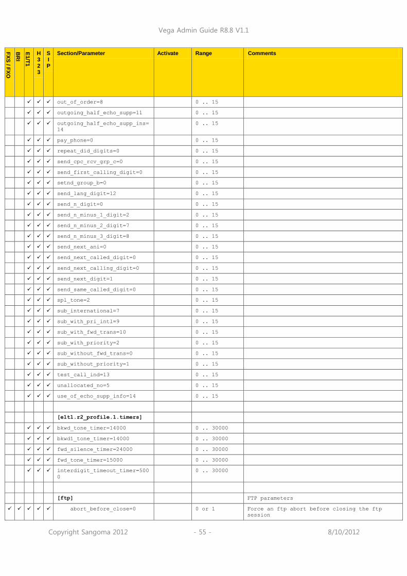
Vega Admin Guide R8.8 V1.1
Copyright Sangoma 2012 - 55 - 8/10/2012
FX
S / F
XO
BR
I
E1/T
1
H 3 2 3
S I P
Section/Parameter Activate Range Comments
out_of_order=8 0 .. 15
outgoing_half_echo_supp=11 0 .. 15
outgoing_half_echo_supp_ins=
14
0 .. 15
pay_phone=0 0 .. 15
repeat_did_digits=0 0 .. 15
send_cpc_rcv_grp_c=0 0 .. 15
send_first_calling_digit=0 0 .. 15
setnd_group_b=0 0 .. 15
send_lang_digit=12 0 .. 15
send_n_digit=0 0 .. 15
send_n_minus_1_digit=2 0 .. 15
send_n_minus_2_digit=7 0 .. 15
send_n_minus_3_digit=8 0 .. 15
send_next_ani=0 0 .. 15
send_next_called_digit=0 0 .. 15
send_next_calling_digit=0 0 .. 15
send_next_digit=1 0 .. 15
send_same_called_digit=0 0 .. 15
spl_tone=2 0 .. 15
sub_international=7 0 .. 15
sub_with_pri_intl=9 0 .. 15
sub_with_fwd_trans=10 0 .. 15
sub_with_priority=2 0 .. 15
sub_without_fwd_trans=0 0 .. 15
sub_without_priority=1 0 .. 15
test_call_ind=13 0 .. 15
unallocated_no=5 0 .. 15
use_of_echo_supp_info=14 0 .. 15
[e1t1.r2_profile.1.timers]
bkwd_tone_timer=14000 0 .. 30000
bkwd1_tone_timer=14000 0 .. 30000
fwd_silence_timer=24000 0 .. 30000
fwd_tone_timer=15000 0 .. 30000
interdigit_timeout_timer=500
0
0 .. 30000
[ftp] FTP parameters
abort_before_close=0 0 or 1 Force an ftp abort before closing the ftp
session
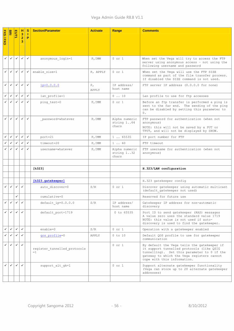
Vega Admin Guide R8.8 V1.1
Copyright Sangoma 2012 - 56 - 8/10/2012
FX
S / F
XO
BR
I
E1/T
1
H 3 2 3
S I P
Section/Parameter Activate Range Comments
anonymous_login=1 P,IMM 0 or 1 When set the Vega will try to access the FTP
server using anonymous access – not using the
following username and password
enable_size=1 P, APPLY 0 or 1 When set the Vega will use the FTP SIZE
command as part of the file transfer process.
If disabled the SIZE command is not used.
ip=0.0.0.0 P,
APPLY
IP address/
host name
FTP server IP address (0.0.0.0 for none)
lan_profile=1 0 .. 10 Lan profile to use for ftp accesses
ping_test=0 P,IMM 0 or 1 Before an ftp transfer is performed a ping is
sent to the far end. The sending of the ping
can be disabled by setting this parameter to
0.
_password=whatever P,IMM Alpha numeric
string 1..64
chars
FTP password for authentication (when not
anonymous)
NOTE: this will not be saved by a PUT or
TPUT, and will not be displayed by SHOW.
port=21 P,IMM 1 .. 65535 IP port number for FTP
timeout=20 P,IMM 1 .. 60 FTP timeout
username=whatever P,IMM Alpha numeric
string 1..32
chars
FTP username for authentication (when not
anonymous)
[h323] H.323/LAN configuration
[h323.gatekeeper] H.323 gatekeeper config
auto_discover=0 S/R 0 or 1 Discover gatekeeper using automatic multicast
(default_gatekeeper not used)
cumulative=0 Reserved for future use
default_ip=0.0.0.0 S/R IP address/
host name
Gatekeeper IP address for non-automatic
discovery
default_port=1719 0 to 65535 Port ID to send gatekeeper (RAS) messages
A value zero uses the standard value 1719
NOTE: this value is not used if auto-
discovery is used to find the gatekeeper.
enable=0 S/R 0 or 1 Operation with a gatekeeper enabled
qos_profile=0 APPLY 0 to 10 Default QOS profile to use for gatekeeper
communication
register_tunnelled_protocols
=1
0 or 1 By default the Vega tells the gatekeeper if
it support tunnelled protocols (like QSIG
tunnelling). Set this parameter to 0 if the
gateway to which the Vega registers cannot
cope with this information.
support_alt_gk=1 0 or 1 Support alternate gatekeeper functionality
(Vega can store up to 20 alternate gatekeeper
addresses)

Vega Admin Guide R8.8 V1.1
Copyright Sangoma 2012 - 57 - 8/10/2012
FX
S / F
XO
BR
I
E1/T
1
H 3 2 3
S I P
Section/Parameter Activate Range Comments
[h323.gatekeeper.terminal_al
ias.1]
Gateway terminal alias list
name=NULL S/R Length<32 Alias string; NULL=do not send terminal alias
type=h323 S/R url/email/e16
4/h323
Alias type
[h323.if.1] H.323 logical interface behaviour (at present
only 1 interface is supported)
cost=1 S/R 0-9 Not used
default_ip=0.0.0.0 APPLY IP address/
host name
IP address/host name of default destination
H.323 device
default_port=1720 APPLY 1 to 65535 IP port of default destination H.323 device
interface=05 S/R Length<32 Interface ID of LAN interface
max_calls=60 S/R E1: 1..120
T1: 1..96
Vega 50: 1..16
Vega 5000:
1..48
Maximum allowable calls in progress
profile=1 0 to 10 Select H.323.profile to use for this
interface
qos_profile=0 APPLY 0 to 10 Default QOS profile to use for H.323 Vegas
serviceprofile=0 APPLY 0 to 10 H.450 supplementary service profile to use,
0=disabled, 1-10 define profile
setup_mapping_index=1 APPLY Index value,
0 to 10
Mapping entry to use from
_advanced.setup_mapping for H.323
signal_port_range=6 1 to 40 Specifies which port range list
(_advanced.port_range_list.x) to use to
define the range of local IP ports to use for
h.245 signalling
[h323.profile.1] Per call behavior (at present only 1 profile
is supported)
- selected by h323.if.x.profile

Vega Admin Guide R8.8 V1.1
Copyright Sangoma 2012 - 58 - 8/10/2012
FX
S / F
XO
BR
I
E1/T
1
H 3 2 3
S I P
Section/Parameter Activate Range Comments
accept_early_h245=1 APPLY 0 or 1 Allow early H.245 on incoming calls
use_early_h245=0 APPLY 0 or 1 Use early H.245 for outgoing calls
(Use_fast_start and use_early_h245 are
mutually exclusive – select only one; if both
are selected use_fast_start overrides
use_early_h245)
accept_fast_start=1 APPLY 0, 1, 2 or 3 Allow fast start on incoming calls (1=accept
with CONNECT message, 2=accept with ALERTING
message, 3=accept with call proceeding)
use_fast_start=1 APPLY 0 or 1 Use fast start for outgoing calls
(Use_fast_start and use_early_h245 are
mutually exclusive – select only one)
h245_after_fast_start=1 APPLY 0 or 1 Create an H.245 channel after a fast start
connection
accept_h245_tunnel=1 APPLY 0 or 1 Allow use of h.245 tunnelling on inbound
H.323 calls
use_h245_tunnel=1 APPLY 0 or 1 Try to use h.245 tunnelling on outbound H.323
calls
capset=1 APPLY 0 to 10 Codec capability set (profile) to use for any
actions that require a codec capability list,
except for faststart calls which uses
faststart_capset
faststart_capset=1 APPLY 0 to 10 Codec capability set (profile) to use when
initiating a call using faststart.
fax_relay=1 0 or 1 1=enable fax relay using T.38 or G.711
upspeeding
force_early_h245=1 0 or 1 Usually the calling party requests early
h.245 (n the SETUP message). If
force_early_h245=1, the Vega as a called
party will request early h.245 if the calling
party has not requested it.
modem_relay=1 0 or 1 1=enable modem relay using G.711 upspeeding
oob_method=signal signal,
alphanumeric
or none
Method to use for transmitting Out Of Band
DTMF information
h225_version=0 S/R 0 to 3 Set the h.225 version that is output in the
Q.931 part of H.323 calls. 0 means the real
(RAD stack) version number is reported, other
values force that artificial value.
rtd_interval=0 S/R 0 to 60 Round trip delay interval between
transmitting RTD response requests – set to
non zero to enable. (Typical value=10
(seconds))
rtd_retries=3 S/R 0 .. 32 Number of retries before failing link
setup_info_in_uui=0 S/R 0 or 1 disable/enable proprietary encoding and
transfer of calling party presentation and
screening indications via user-user-
information
setup_sending_complete=0 S/R 0 or 1 disable/enable inclusion of sending complete
information element in outgoing H.323 setup
message
tx_media_before_connect=0 0 or 1 This parameter only affects telephony to
H.323 calls.
If set to 0, then RTP data is not generated

Vega Admin Guide R8.8 V1.1
Copyright Sangoma 2012 - 59 - 8/10/2012
FX
S / F
XO
BR
I
E1/T
1
H 3 2 3
S I P
Section/Parameter Activate Range Comments
by the Vega until the CONNECT message is
received from the H.323 interface.
If set to 1, then RTP data is generated as
soon as the H.323 protocol negotiations
allow.
[http]
https_ip=0.0.0.0 IP address/
host name
IP address for https server (for put, get and
cron)
https_port=443 1 .. 65535 IP port number for https server (for put, get
and cron)
ip=0.0.0.0 IP address/
host name
IP address for http server (for put, get and
cron)
lan_profile=1 0 .. 10 Lan profile for http server access
ping_test=0 0 or 1 Do a ping test before accessing http server?
port=80 1 .. 65535 IP port number for http server (for put, get
and cron)
timeout=30 1 .. 60 http timeout
[http_server]
enable=1 0 .. 1 Enable http access to Vega web browser
lan_profile=1 1 .. 10 Lan profile to use for HTTP / HTTPS web
browser access
port=80 1 .. 65535 IP Port number on which Vega will accept web
browser traffic
[https]
port=443 P,IMM 1 .. 65535 IP Port number on which Vega will accept
HTTPS web browser traffic

Vega Admin Guide R8.8 V1.1
Copyright Sangoma 2012 - 60 - 8/10/2012
FX
S / F
XO
BR
I
E1/T
1
H 3 2 3
S I P
Section/Parameter Activate Range Comments
[lan] LAN parameters
bridge_mode=1 0 or 1 Default = 1 for Europa, = 0 for other
products
0: Vega LAN interfaces are LAN 1 and LAN 2 –
each interface (if used) must be in a
separate IP subnet
1: Vega LAN interfaces are bridged, so that
traffic seen 1 side is duplicated the other –
used for Vega traffic over network traffic
prioritisation.
See also „IN45-Vega_Voice_Prioritisation‟
available in the technical documentation
section of www.wiki.sangoma.com/vega
file_transfer_method=TFTP
IMM FTP / TFTP /
http / https
This config parameter specifies the default
method used for file transfer when the user
does not explicitly specify the desired
method.
name=this_hostame S/R String up to
85 characters
long
Host name (must not contain spaces; use _ or
-)
[lan.gateway]
dhcp_if=1 1 or 2 1..2 - Lan interface to get DHCP IP address
from
0 – do not use DHCP to get gateway IP
ip=0.0.0.0 P,S/R IP address/
host name
Default lan gateway IP/hostname (0.0.0.0 for
none)
[lan.if.1]
ip=0.0.0.0 P,S/R IP address IP address
max_tx_rate=0 0..100000 0: turn off bandwidth handling
1..100000: Limit outgoing bandwidth to this
value kbps.
See also „IN45-Vega_Voice_Prioritisation‟
available in the technical documentation
section of www.wiki.sangoma.com/vega
protocol=ip S/R ip Protocol to use for this LAN port. Currently
only ip supported
qos_profile=1 S/R 1-10 QOS profile to use for this LAN port
subnet=255.255.255.0 P,S/R IP mask Subnet mask
use_apipa=1 S/R 0 or 1 Enable Vega to select a 169.254.xxx.yyy
address if no DHCP IP address is supplied
when asked for. (Interoperates with APIPA
created IP addresses on PCs)
use_dhcp=1 P,S/R 0 or 1 0 = use static configurations
1 = use DHCP server on this interface to set
up IP values for Vega IP address and subnet,
and optionally dns, lan gateway, ntp and tftp
addresses

Vega Admin Guide R8.8 V1.1
Copyright Sangoma 2012 - 61 - 8/10/2012
FX
S / F
XO
BR
I
E1/T
1
H 3 2 3
S I P
Section/Parameter Activate Range Comments
[lan.if.1.dhcp] DHCP parameters
get_dns=1 0 or 1 If get_dns=1 and use_dhcp=1 and dns.dhcp_if =
this interface, then get DNS address from the
DHCP server on this interface
get_dns_suffix=1 0 or 1 If get_dns_suffix=1 and use_dhcp=1 and
dns.dhcp_if = this interface, then get DNS
suffix name from the DHCP server on this
interface
get_gateway=1 0 or 1 If get_gateway=1 and use_dhcp=1 then get LAN
gateway address from the DHCP server on this
interface
get_ntp=1 0 or 1 If get_ntp=1 and use_dhcp=1 and ntp.dhcp_if =
this interface, then get NTP server address
from the DHCP server on this interface
get_tftp=1 0 or 1 If get_tftp=1 and use_dhcp=1 and tftp.dhcp_if
= this interface, then get TFTP server
address from the DHCP server on this
interface
[lan.if.1.nat]
enable=0 APPLY 0 or 1 Disable or enable NAT handling on the Vega
private_subnet_auto=1 APPLY 0 or 1 Automatically populates the list of private
subnets.
private_subnet_list_index=1 APPLY 1 to 255 Select a list of subnets that are the local
subnets, i.e. points to
lan.private_subnet_list.x
[lan.if.1.nat.profile.1]
external_ip=0.0.0.0 APPLY 0 to 65535 Public IP address of NAT server
port_list_index=0 APPLY 0 to 255 Index into lan.nat.port_list.x – associates
that set of port_ranges to this external IP
address
[lan.if.1.phy] LAN – physical layer config
full_duplex=0 P,S/R 0 or 1 Allow full duplex mode to be used on the LAN
if other end supports it. Default =1 on E1T1
Vega.
10baset=1 P,S/R 0 or 1 Allow 10 Mpbs operation
100basetx=1 P,S/R 0 or 1 Allow 100 Mbps operation
[lan.if.1.8021q] 802.1p/q enable
accept_non_tagged=1 APPLY 0 or 1 Accept non 802.1 LAN packets as well as 802.1
LAN packets
qos_profile=0 APPLY 0 or 1 QOS profile to use for 802.1q packet tagging.

Vega Admin Guide R8.8 V1.1
Copyright Sangoma 2012 - 62 - 8/10/2012
FX
S / F
XO
BR
I
E1/T
1
H 3 2 3
S I P
Section/Parameter Activate Range Comments
[lan.localDNS.1] LAN – local DNS name table
ip=127.0.0.1 APPLY IP address IP address of this device
name=loopback APPLY length<32 Name of this device
[lan.localDNSSRV.1] LAN – local DNSSRV name table
enable=0 APPLY 0, 1 Enable or disale use of local DNSSRV look ups
service_name=sip._udp.new_dn
ssrv
APPLY Character
String
Name of local DNSSRV record. Any DNSSRV
record lookups will check this list first
before sending to external DNS servers
[lan.localDNSSRV.1.srvrec.1]
ipname=0.0.0.0 APPLY IP address IP address for first DNSSRV record entry
port=0 APPLY 0 – 65535 Port to send the SIP messaging.
priority=1 APPLY 1 - 1000 Relative priority of this record
weight=0 APPLY 0 – 10000 relative weight of this record
[lan.nat.port_entry.1]
external_port_min=0 APPLY 0 to 65535 Start of NATed port range on server
internal_port_range_index=0
APPLY 0 to 40 Index into _advanced.lan.port_range.x – the
range of IP port numbers that map onto this
NATed range
name=port_name APPLY length<32 Name – for self documentation purposes
[lan.nat.port_list.1]
list=all APPLY all,
or
x,y,z
all – select all lan.nat.port_entry.x
x,y,z - a comma separated list of nat port
entries (lan.nat.port_entry.?)
name=default_port_list APPLY length<32 Name – for self documentation purposes

Vega Admin Guide R8.8 V1.1
Copyright Sangoma 2012 - 63 - 8/10/2012
FX
S / F
XO
BR
I
E1/T
1
H 3 2 3
S I P
Section/Parameter Activate Range Comments
[lan.private_subnet.1] First of up to 40 subnet definitions
ip=0.0.0.0 APPLY IP address Base IP address of subnet
name=subnet_name APPLY length<32 Name – for self documentation purposes
subnet=255.255.255.0 APPLY Subnet mask Subnet mask of this subnet
[lan.private_subnet_list.1]
list=all APPLY all,
or
x,y,z
all – select all lan.private.subnet.x
x,y,z - a comma separated list of local
subnet definitions (lan.private.subnet.?)
name=default_subnet_list APPLY length<32 Name – for self documentation purposes
[lan.static_route.1] Static Routes
dest=0.0.0.0 IP address Base IP address of destination subnet
enable=0 0 or 1 Disable / Enable this Static Route entry
gateway=0.0.0.0 IP address IP address to send packets to in order to get
to the „dest‟ subnet
subnet=255.255.255.0 IP mask Subnet mask of the destination subnet (i.e.
defines how many IP addresses ther are in the
destination subnet)
[lan_profile.1] First of 10 possible lan profiles
lan_interface=1 0, 1, 2 Specifies which physical LANs are included in
this profile
0 means both LAN interfaces 1 and 2
name=LAN_1 Length<32,
no spaces
Name of LAN profile – for self documentation
and pull down selection
qos_profile=1 0 to 10 Qos profile to use as default or this LAN
profile
[logger] Event/billing logger/console
bill_warn_threshold=90 APPLY 1-99 % bill log full to generate alert message
DST_adjust=1 APPLY 0 / 1 0: use base local time for Caller ID time
1: use Daylight Saving Time for Caller ID
time
max_billings=100 APPLY 10-300 Max number of messages in billing log buffer
max_messages=300 APPLY 10-300 Max number of messages in circular event log
buffer
prompt=%n%p> APPLY Length<32 Obsolete parameter – no longer used

Vega Admin Guide R8.8 V1.1
Copyright Sangoma 2012 - 64 - 8/10/2012
FX
S / F
XO
BR
I
E1/T
1
H 3 2 3
S I P
Section/Parameter Activate Range Comments
[logger.radius] Radius Accounting CDR handling
lan_profile=1 0 .. 10 Lan profile to use for Radius
max_retry_time=4000 APPLY 1 to 40000 Maximum retry timer for retransmissions
(milliseconds)
name=this_radius_hostname
APPLY Length <= 31
characters
NAS (Network Access Server – gateway)
identifier
retries=4 APPLY 1 .. 100 Max retries used to send a specific
accounting message
retry_time=500 APPLY 1 .. 5000 Initial timeout before first retry
(milliseconds)
… time doubles for each retry (but limits at
max_retry_time)
window_size=10 APPLY 1 .. 256 Maximum number of accounting messages that
can be sent to the server before receiving a
response.
[logger.radius.attributes] Radius Accounting CDR handling
overload_session_id=cisco_co
mpatible_format
APPLY vega_format,
cisco_compatib
le_format,
cisco_vsa or
off
Select desired format of Radius Accounting
record
- overloaded acct_session_id – Vega format
- overloaded acct_session_id – Cisco
compatible format
- Vendor Specific Attributes, Cisco
compatible format

Vega Admin Guide R8.8 V1.1
Copyright Sangoma 2012 - 65 - 8/10/2012
FX
S / F
XO
BR
I
E1/T
1
H 3 2 3
S I P
Section/Parameter Activate Range Comments
[logger.radius.attributes.ac
counting]
Radius Accounting CDR handling (RFC 2139)
(Radius TYPE fields 40 to 51)
acct_delay_time=1 APPLY 0 or 1 1 = include indication of delay incurred
before this record was sent
Radius TYPE = 41
acct_input_octets=1 APPLY 0 or 1 1 = include count of RTP media bytes received
for this call – only available in STOP
records, and if the QOS statistics module
is enabled
Radius TYPE = 42
acct_output_octets=1 APPLY 0 or 1 1 = include count of RTP media bytes sent for
this call – only available in STOP
records, and if the QOS statistics module
is enabled
Radius TYPE = 43
acct_session_id=1 APPLY 0 or 1 1 = include session ID … this is the field
that contains the CDR information when
overload_session_id = vega_format or
cisco_compatible_format
Radius TYPE = 44
acct_session_time=1 APPLY 0 or 1 1 = include session time field = duration of
call in seconds
Radius TYPE = 46
acct_status_type=1 APPLY 0 or 1 1 = include record type, i.e. indicate
Accounting on/off for registration/de-
registration records and Start/Stop for
call records
Radius TYPE = 40
acct_terminate_cause=1 APPLY 0 or 1 1 = include call terminatinion reason in STOP
records
Radius TYPE = 49
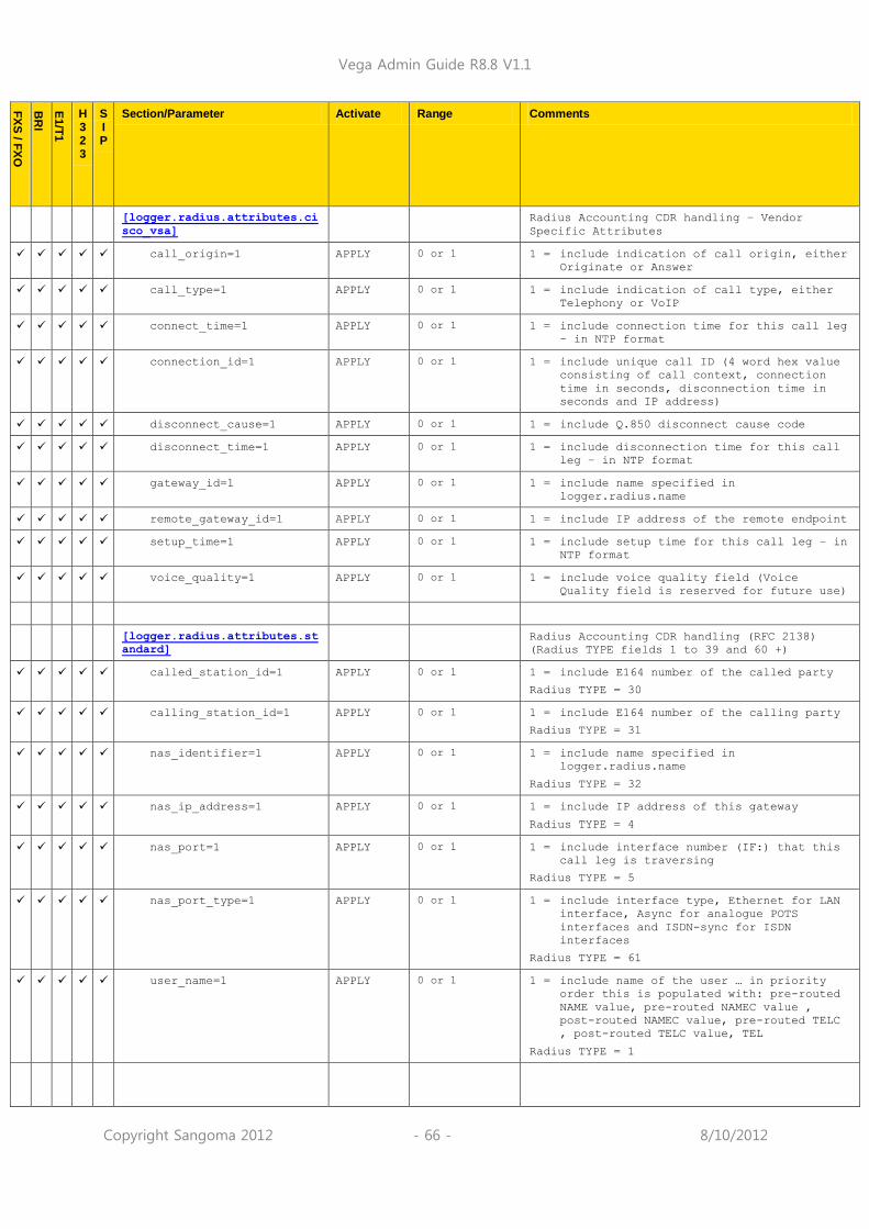
Vega Admin Guide R8.8 V1.1
Copyright Sangoma 2012 - 66 - 8/10/2012
FX
S / F
XO
BR
I
E1/T
1
H 3 2 3
S I P
Section/Parameter Activate Range Comments
[logger.radius.attributes.ci
sco_vsa]
Radius Accounting CDR handling – Vendor
Specific Attributes
call_origin=1 APPLY 0 or 1 1 = include indication of call origin, either
Originate or Answer
call_type=1 APPLY 0 or 1 1 = include indication of call type, either
Telephony or VoIP
connect_time=1 APPLY 0 or 1 1 = include connection time for this call leg
– in NTP format
connection_id=1 APPLY 0 or 1 1 = include unique call ID (4 word hex value
consisting of call context, connection
time in seconds, disconnection time in
seconds and IP address)
disconnect_cause=1 APPLY 0 or 1 1 = include Q.850 disconnect cause code
disconnect_time=1 APPLY 0 or 1 1 = include disconnection time for this call
leg – in NTP format
gateway_id=1 APPLY 0 or 1 1 = include name specified in
logger.radius.name
remote_gateway_id=1 APPLY 0 or 1 1 = include IP address of the remote endpoint
setup_time=1 APPLY 0 or 1 1 = include setup time for this call leg – in
NTP format
voice_quality=1 APPLY 0 or 1 1 = include voice quality field (Voice
Quality field is reserved for future use)
[logger.radius.attributes.st
andard]
Radius Accounting CDR handling (RFC 2138)
(Radius TYPE fields 1 to 39 and 60 +)
called_station_id=1 APPLY 0 or 1 1 = include E164 number of the called party
Radius TYPE = 30
calling_station_id=1 APPLY 0 or 1 1 = include E164 number of the calling party
Radius TYPE = 31
nas_identifier=1 APPLY 0 or 1 1 = include name specified in
logger.radius.name
Radius TYPE = 32
nas_ip_address=1 APPLY 0 or 1 1 = include IP address of this gateway
Radius TYPE = 4
nas_port=1 APPLY 0 or 1 1 = include interface number (IF:) that this
call leg is traversing
Radius TYPE = 5
nas_port_type=1 APPLY 0 or 1 1 = include interface type, Ethernet for LAN
interface, Async for analogue POTS
interfaces and ISDN-sync for ISDN
interfaces
Radius TYPE = 61
user_name=1 APPLY 0 or 1 1 = include name of the user … in priority
order this is populated with: pre-routed
NAME value, pre-routed NAMEC value ,
post-routed NAMEC value, pre-routed TELC
, post-routed TELC value, TEL
Radius TYPE = 1
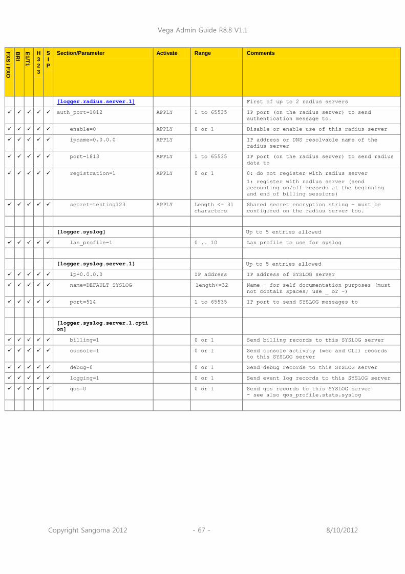
Vega Admin Guide R8.8 V1.1
Copyright Sangoma 2012 - 67 - 8/10/2012
FX
S / F
XO
BR
I
E1/T
1
H 3 2 3
S I P
Section/Parameter Activate Range Comments
[logger.radius.server.1] First of up to 2 radius servers
auth_port=1812 APPLY 1 to 65535 IP port (on the radius server) to send
authentication message to.
enable=0 APPLY 0 or 1 Disable or enable use of this radius server
ipname=0.0.0.0 APPLY IP address or DNS resolvable name of the
radius server
port=1813 APPLY 1 to 65535 IP port (on the radius server) to send radius
data to
registration=1 APPLY 0 or 1 0: do not register with radius server
1: register with radius server (send
accounting on/off records at the beginning
and end of billing sessions)
secret=testing123 APPLY Length <= 31
characters
Shared secret encryption string – must be
configured on the radius server too.
[logger.syslog] Up to 5 entries allowed
lan_profile=1 0 .. 10 Lan profile to use for syslog
[logger.syslog.server.1] Up to 5 entries allowed
ip=0.0.0.0 IP address IP address of SYSLOG server
name=DEFAULT_SYSLOG length<=32 Name – for self documentation purposes (must
not contain spaces; use _ or -)
port=514 1 to 65535 IP port to send SYSLOG messages to
[logger.syslog.server.1.opti
on]
billing=1 0 or 1 Send billing records to this SYSLOG server
console=1 0 or 1 Send console activity (web and CLI) records
to this SYSLOG server
debug=0 0 or 1 Send debug records to this SYSLOG server
logging=1 0 or 1 Send event log records to this SYSLOG server
qos=0 0 or 1 Send qos records to this SYSLOG server
- see also qos_profile.stats.syslog
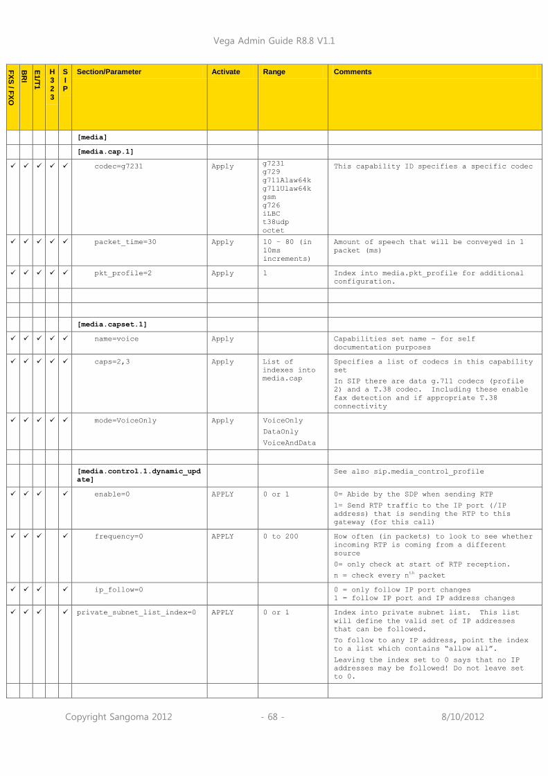
Vega Admin Guide R8.8 V1.1
Copyright Sangoma 2012 - 68 - 8/10/2012
FX
S / F
XO
BR
I
E1/T
1
H 3 2 3
S I P
Section/Parameter Activate Range Comments
[media]
[media.cap.1]
codec=g7231 Apply g7231
g729
g711Alaw64k
g711Ulaw64k
gsm
g726
iLBC
t38udp
octet
This capability ID specifies a specific codec
packet_time=30 Apply 10 – 80 (in
10ms
increments)
Amount of speech that will be conveyed in 1
packet (ms)
pkt_profile=2 Apply 1 Index into media.pkt_profile for additional
configuration.
[media.capset.1]
name=voice Apply Capabilities set name – for self
documentation purposes
caps=2,3 Apply List of
indexes into
media.cap
Specifies a list of codecs in this capability
set
In SIP there are data g.711 codecs (profile
2) and a T.38 codec. Including these enable
fax detection and if appropriate T.38
connectivity
mode=VoiceOnly Apply VoiceOnly
DataOnly
VoiceAndData
[media.control.1.dynamic_upd
ate]
See also sip.media_control_profile
enable=0 APPLY 0 or 1 0= Abide by the SDP when sending RTP
1= Send RTP traffic to the IP port (/IP
address) that is sending the RTP to this
gateway (for this call)
frequency=0 APPLY 0 to 200 How often (in packets) to look to see whether
incoming RTP is coming from a different
source
0= only check at start of RTP reception.
n = check every nth packet
ip_follow=0 0 = only follow IP port changes
1 = follow IP port and IP address changes
private_subnet_list_index=0 APPLY 0 or 1 Index into private subnet list. This list
will define the valid set of IP addresses
that can be followed.
To follow to any IP address, point the index
to a list which contains “allow all”.
Leaving the index set to 0 says that no IP
addresses may be followed! Do not leave set
to 0.
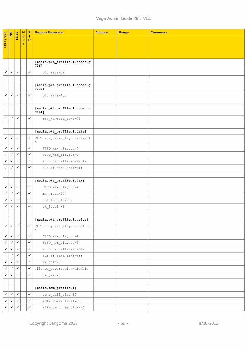
Vega Admin Guide R8.8 V1.1
Copyright Sangoma 2012 - 69 - 8/10/2012
FX
S / F
XO
BR
I
E1/T
1
H 3 2 3
S I P
Section/Parameter Activate Range Comments
[media.pkt_profile.1.codec.g
726]
bit_rate=32
[media.pkt_profile.1.codec.g
7231]
bit_rate=6.3
[media.pkt_profile.1.codec.o
ctet]
rtp_payload_type=98
[media.pkt_profile.1.data]
FIFO_adaptive_playout=disabl
e
FIFO_max_playout=4
FIFO_nom_playout=2
echo_canceller=disable
out-of-band-dtmf=off
[media.pkt_profile.1.fax]
FIFO_max_playout=4
max_rate=144
tcf=transferred
tx_level=-8
[media.pkt_profile.1.voice]
FIFO_adaptive_playout=silenc
e
FIFO_max_playout=4
FIFO_nom_playout=2
echo_canceller=enable
out-of-band-dtmf=off
rx_gain=0
silence_suppression=disable
tx_gain=0
[media.tdm_profile.1]
echo_tail_size=32
idle_noise_level=-50
silence_threshold=-40
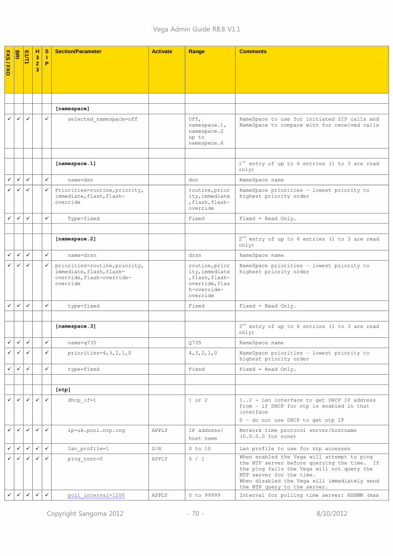
Vega Admin Guide R8.8 V1.1
Copyright Sangoma 2012 - 70 - 8/10/2012
FX
S / F
XO
BR
I
E1/T
1
H 3 2 3
S I P
Section/Parameter Activate Range Comments
[namespace]
selected_namespace=off Off,
namespace.1,
namespace.2
up to
namespace.6
NameSpace to use for initiated SIP calls and
NameSpace to compare with for received calls
[namespace.1] 1st entry of up to 6 entries (1 to 3 are read
only)
name=dsn dsn NameSpace name
Priorities=routine,priority,
immediate,flash,flash-
override
routine,prior
ity,immediate
,flash,flash-
override
NameSpace priorities – lowest priority to
highest priority order
Type=fixed Fixed Fixed = Read Only.
[namespace.2] 2nd entry of up to 6 entries (1 to 3 are read
only)
name=drsn drsn NameSpace name
priorities=routine,priority,
immediate,flash,flash-
override,flash-override-
override
routine,prior
ity,immediate
,flash,flash-
override,flas
h-override-
override
NameSpace priorities – lowest priority to
highest priority order
type=fixed Fixed Fixed = Read Only.
[namespace.3] 3rd entry of up to 6 entries (1 to 3 are read
only)
name=q735 Q735 NameSpace name
priorities=4,3,2,1,0 4,3,2,1,0 NameSpace priorities – lowest priority to
highest priority order
type=fixed Fixed Fixed = Read Only.
[ntp]
dhcp_if=1 1 or 2 1..2 - Lan interface to get DHCP IP address
from – if DHCP for ntp is enabled in that
interface
0 – do not use DHCP to get ntp IP
ip=uk.pool.ntp.org APPLY IP address/
host name
Network time protocol server/hostname
(0.0.0.0 for none)
lan_profile=1 S/R 0 to 10 Lan profile to use for ntp accesses
ping_test=0 APPLY 0 / 1 When enabled the Vega will attempt to ping
the NTP server before querying the time. If
the ping fails the Vega will not query the
NTP server for the time.
When disabled the Vega will immediately send
the NTP query to the server.
poll_interval=1200 APPLY 0 to 99999 Interval for polling time server: HHHMM (max

Vega Admin Guide R8.8 V1.1
Copyright Sangoma 2012 - 71 - 8/10/2012
FX
S / F
XO
BR
I
E1/T
1
H 3 2 3
S I P
Section/Parameter Activate Range Comments
999hrs + 99 mins)
port=123 APPLY 1 to 65535 IP port number for NTP
[phone_context] Phone context section
[phone_context.local.1]
enable=1 0 or 1 Enable phone-context inclusion in FROM header
(globally)
[phone_context.local.1.pc.1]
NPI=any any/unknown
/isdn_telepho
ny/data/telex
/national/
private
Use specific phone-context when Numbering plan
information received in ISDN SETUP matches
defined NPI value.
TON=any any/unknown/i
nternational/
national/netw
ork_specific/
subscriber/ab
breviated
Use specific phone-context when Type Of Number
information received in ISDN SETUP matches
defined TON value.
enable=0 0 or 1 Enable / disable specific phone-context
defition
name=local_phone.1.com String up to
63 chars
Name of specific phone-context defintion
[phone_context.remote.1]
enable=1 0 or 1 Enable phone-context inclusion in TO header
(globally)
[phone_context.remote.1.pc.1]
NPI=any any/unknown
/isdn_telepho
ny/data/telex
/national/
private
Use specific phone-context when Numbering plan
information received in ISDN SETUP matches
defined NPI value.
TON=any any/unknown/i
nternational/
national/netw
ork_specific/
subscriber/ab
breviated
Use specific phone-context when Type Of Number
information received in ISDN SETUP matches
defined TON value.
enable=0 0 or 1 Enable / disable specific phone-context
defition
name=remote_phone.1.com String up to
63 chars
Name of specific phone-context defintion
[planner] Dial planner section
allow_tx_overlap=0 0 or 1 When enabled allow the Vega to originate
calls using overlap dialling, if disabled use
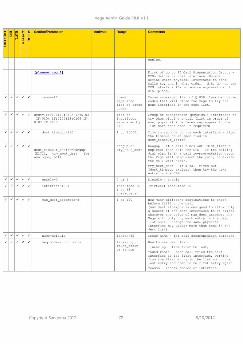
Vega Admin Guide R8.8 V1.1
Copyright Sangoma 2012 - 72 - 8/10/2012
FX
S / F
XO
BR
I
E1/T
1
H 3 2 3
S I P
Section/Parameter Activate Range Comments
enbloc.
[planner.cpg.1] First of up to 40 Call Presentation Groups –
CPGs define virtual interface IDs which
define which physical interfaces to send
calls to, and in what order. N.B. do not use
CPG interface IDs in source expressions of
dial plans.
cause=17 comma
separated
list of cause
codes
Comma separated list of Q.850 cleardown cause
codes that will cause the vega to try the
next interface in the dest list.
dest=IF:0101|IF:0102|IF:0103
|IF:0104|IF:0105|IF:0106|IF:
0107|IF:0108
list of
interfaces,
separated by
„|‟
Group of destination (physical) interfaces to
try when placing a call (list in order of
use; physical interfaces may appear in the
list more than once if required)
dest_timeout=180 1 .. 10000 Time in seconds to try each interface – after
the timeout do as specified in
dest_timeout_action
dest_timeout_action=hangup
(E1T1), try_next_dest (for
analogue, BRI)
hangup or
try_next_dest
hangup - if a call times out (dest_timeout
expires) then exit the CPG – if the calling
dial plan is in a call re-presentation group,
the Vega will re-present the call, otherwise
the call will clear.
try_next_dest - if a call times out
(dest_timeout expires) then try the next
entry in the CPG
enable=0 0 or 1 Disable / enable
interface=1001 interface ID
1 to 63
characters
(Virtual) Interface ID
max_dest_attempts=8 1 to 120 How many different destinations to check
before failing the call
(max_dest_attempts is designed to allow only
a subset of the dest interfaces to be tried;
whatever the value of max_dest_attempts the
Vega will only try each entry in the dest
list once – though the same physical
interface may appear more than once in the
dest list)
name=default length<32 Group name – for self documentation purposes
seq_mode=round_robin linear_up,
round_robin
or random
How to use dest list:
linear_up - from first to last,
round_robin – each call tries the next
interface as its first interface, working
from the first entry in the list up to the
last entry and then to te first entry again
random – random choice of interface

Vega Admin Guide R8.8 V1.1
Copyright Sangoma 2012 - 73 - 8/10/2012
FX
S / F
XO
BR
I
E1/T
1
H 3 2 3
S I P
Section/Parameter Activate Range Comments
[planner.file_plans]
max=0 APPLY 1 to 10000 Maximum number of lines that can be specified
in the dial plan text file.
non_local_prefix=0 APPLY String
between 1 and
11 characters
Prefix that will be added when a user dials a
non-local number.
[planner.group] Groups for redundant routes
[planner.group.1] Up to 10 planner.group.x
name=default APPLY length<32 Group name – for self documentation purposes
active_times=0000-2359 APLY Disable dial plans in this group outside the
active times.
Start HHMM to end HHMM – times are inclusive
cause=0 APPLY comma
separated
list of
values
0 to 127
Applicable cause code list for this group
priority=0 APPLY 0 or 1 Treat calls that match this group as prority.
[planner.post_profile]
enable=0 APPLY 0 or 1 disable or enable all post_profile entries
[planner.post_profile.plan.1
]
Up to 20 plans
name=International APPLY length<32 Plan name – for self documentation purposes
enable=0 APPLY 0 or 1 disable or enable this post_profile entry
srce= TEL:00<.*> APPLY IF:
TEL:
TA:
NAME:
TAC:
TELC:
DISP:
dest= TYPE:international APPLY TYPE:
PLAN:
TYPEC:
PLANC:
PRESC:
SCRNC:
TELC:
DISP:
TYPE: populate the called party number “Type
Of Number” field with: national,
International, network_specific,
subscriber, abbreviated, and unknown PLAN: populate the called party number
“Numbering Plan Information” field with:
isdn_telephony, data, telex, national,
private, and unknown
TYPEC: populate the calling party number “Type
Of Number” field with: national,
international, network_specific,
subscriber, abbreviated, or unknown PLANC: populate the calling party number
“Numbering Plan Information” field with:
isdn_telephony, data, telex, national,

Vega Admin Guide R8.8 V1.1
Copyright Sangoma 2012 - 74 - 8/10/2012
FX
S / F
XO
BR
I
E1/T
1
H 3 2 3
S I P
Section/Parameter Activate Range Comments
private,or unknown
PRESC: populate the calling party PRESENTATION
indicator with: allowed, not_available, or
restricted
SCRNC: populate the calling party SCREENING
indicator with: failed4, not_screened,
passed, or network
TELC: caller ID (ANI)
DISP: display field
[planner.profile.1] Profile 1 (up to 25 profiles)
name=new_profile APPLY length<32 Profile name – for self documentation
purposes
enable=0 APPLY 0 or 1 Disable / enable this profile
[planner.profile.1.plan.1] First plan (up to 50 plans per profile)
name=new_plan APPLY length<32 Plan name – for self documentation purposes
srce=TEL:<....><.*> APPLY IF:
TEL:
TA:
NAME:
TAC:
TELC:
DISP:
Source (incoming) expression to match
(see section 9)
dest=IF:<1>,TEL:<2> APPLY IF:
TEL:
TA:
NAME:
TAC:
TELC:
DISP:
QOS:
CAPDESC:
NAMEC:
TYPE:
TYPEC:
PLAN:
PLANC:
SCRNC:
PRESC:
Destination (outgoing) expression to create
(see section 9)
group=0 APPLY index, or
zero
Used to group dial plans together, and also
act as an index into planner.group parameters
to be used with this plan
cost=0 APPLY 0-9 Plan cost index
[planner.whitelist] Whitelist section – up to 50 entries
4 „failed‟ is not a valid ETSI value (even though it is defined in Q.931)

Vega Admin Guide R8.8 V1.1
Copyright Sangoma 2012 - 75 - 8/10/2012
FX
S / F
XO
BR
I
E1/T
1
H 3 2 3
S I P
Section/Parameter Activate Range Comments
enable=0 APPLY 0 or 1 disable / enable whitelist security
[planner.whitelist.1] First whitelist entry (up to 50 entries
allowed)
name=default IMM length<32 Name of this white list – for self
documentation purposes
number=IF:.* APPLY length<64 Expression defining who/where to accept calls
from (see section 9.14)
[pots] POTS (telephone handset) config
[pots.port.1]
call_conference=off APPLY off, on Enable or disable three way calling for this
port
call_fwd_enable=on APPLY off, on Enable or disable all types of call forward
for this port
call_transfer=on APPLY off, on Enable or disable call transfer for this port
call_waiting=off APPLY off, on Enable or disable call waiting for this port
callerid=off APPLY on, off,
cidcw
Caller ID enable/disable (for caller ID at
start of call, and if the call waiting
supplementary service is enabled when a call
arrives mid call)
dnd_enable=on APPLY off, on Enable or disable Do Not Disturb for this port
dnd_off_hook_deactivate=off APPLY off, on on = Going off-hook on the phone connected to
this port will deactivate DND for this port.
off = going offh-ook on the phone connected to
this port will have no affect on the status of
DND.
dnd_response=instant_reject APPLY Control whether when DND is active the call is
instantly rejected on the SIP side or whether
ringing indication is provided
enable=1 APPLY 0 or 1 disable / enable port
SIP: NOTE this does not disable the port
registering with the SIP proxy; disable
registration as well as disabling the port
fx_profile=1 1 to 10 Hardware profile for this port (see
_advanced.pots.fxs.y or _advanced.pots.fxo.y)
lyr1=g711Alaw64k APPLY g711Alaw64k
or
g711Ulaw64k
Companding codec used on this port
DO NOT ALTER FROM FACTORY DEFAULT – this must
match with the hardware on board.
tdm_profile=1 APPLY 1 to 10 TDM profile to use within the media section
for this interface. Allows echo tail length,
idle noise level and silence threshold to be
defined.
tx_gain=0 APPLY 0 or 1 0 – default gain setting in analogue transmit
hardware
1 – apply additional gain in the analogue
transmit hardware

Vega Admin Guide R8.8 V1.1
Copyright Sangoma 2012 - 76 - 8/10/2012
FX
S / F
XO
BR
I
E1/T
1
H 3 2 3
S I P
Section/Parameter Activate Range Comments
[pots.port.1.if.1]
dn=0101 APPLY length<32 FXS dn = directory number, the Caller ID
(ANI) associated with calls made from that
telephony interface
FXO dn = directory number, the Caller ID
(ANI) associated with calls made from that
telephony interface – if caller ID reception
is turned off
SIP units that register with a SIP Proxy: dn
specifies the nn in the contact address
nn@ip_address_of_vega
interface=0101 APPLY length<32 Interface for this group
profile=1 1 to 10 POTS profile (pots.profile.x) to use to
define profile for this interface
ring_index=1 APPLY Index Index to the distinctive (power) ring pattern
to be used to ring attached phone for FXS
ports only
See _advanced.pots.ring.n
username=FXS1 APPLY length<32 H.323: Name used in display field on calls
originating from POTS interfaces
SIP: Name section used for SIP proxy
registration, and for all other SIP
messagesuse in the From: field
[pots.profile.1] First of up to 10 POTS hardware profiles
(currently up to 2 profiles are supported)
Profile 1 is for FXS, profile 2 is for FXO
F
X
S
callerid_time=DST APPLY base or DST Base: use base local time for Caller ID time
DST: use Daylight Saving Time for Caller ID
time
callerid_type=bt APPLY gr30-sdmf /
gr30-mdmf /
bt / etsi-fsk
/ etsi-fsk-lr
/ etsi-fsk-
post / etsi-
dtmf / etsi-
dtmf-lr /
etsi-dtmf-
post / off
Caller ID encoding method (for analogue only)
NOTE: on an FXO unit, turning this to off
does not stop the Vega waiting to receive the
caller ID (after the first ring), to speed up
call reception on FXO, also turn off caller
ID per port:- pots.port.x.callerid=off
F
X
O
callerid_wait=6000 IMM 10 to 20000 Time (in milli seconds)that an FXO port will
wait for the incoming caller ID after
detecting an incoming power ring.

Vega Admin Guide R8.8 V1.1
Copyright Sangoma 2012 - 77 - 8/10/2012
FX
S / F
XO
BR
I
E1/T
1
H 3 2 3
S I P
Section/Parameter Activate Range Comments
dtmf_dial_digit=# S/R 1 char
* or #, 0 to
9, A to F, or
Z
DTMF dial termination character – the DTMF
character that indicates the dialled number
is complete (overrides dtmf_dial_timeout)
forcing the received number to be passed to
the dial plan router (set to Z to disable
this function)
dtmf_dial_timeout=5 S/R FXS: 1..999
FXO: 0..999
Time after last dialled digit is received
that dialled number is forwarded to the dial
plan router (in seconds)
In the FXO this therefore also specifies the
duration that secondary dial tone is played
for if no dialled digit is received.
FXS: 999 = no timeout used
FXO: 0 = no secondary dial tone played
line_busy_cause=17 APPLY 1 to 127 Cause code to be returned when POTS line is
in use
name=FXS_ports_profile APPLY Up to 32
chars
Name of profile, for self documentation
[pots.profile.2] Profile 2 is for FXO
… as per pots.profile.1,
except
line_busy_cause=34
[qos_profile]
[qos_profile.1] QOS profile (up to 10 profiles are supported)
name=default APPLY Length<=50 Name of this QOS profile – for self
documentation purposes
[qos_profile.1.tos] Ethernet Type Of Service configuration
default_priority=0x00 APPLY 0 to 255 default_priority is used for any LAN traffic
not associated with either call signalling or
call media.
enable=0 APPLY 0 or 1 Enable / disable this QOS profile
media_priority=0x00 APPLY 0 to 255 media_priority is used for media packets, ie
audio RTP packets and T.38 packets
signalling_priority=0x00 APPLY 0 to 255 signalling_priority is used for the VoIP
signalling messages
[qos_profile.1.8021q] 802.1 p/q QOS configuration
default_priority=0 APPLY 0 to 7 default_priority is used for any LAN traffic
not associated with either call signalling or
call media.
media_priority=0 APPLY 0 to 7 media_priority is used for media packets, ie
audio RTP packets and T.38 packets
signalling_priority=0 APPLY 0 to 7 signalling_priority is used for the VoIP
signalling messages
vlan_id=0 APPLY 0 to 4095 VLAN ID for all packets sent out using this
profile

Vega Admin Guide R8.8 V1.1
Copyright Sangoma 2012 - 78 - 8/10/2012
FX
S / F
XO
BR
I
E1/T
1
H 3 2 3
S I P
Section/Parameter Activate Range Comments
vlan_name=Default APPLY Length<=50 Name of this 802.1 p/q QOS profile – for self
documentation purposes
[qos_profile.stats]
cdr_detail=low IMM low, medium,
or high
Level of detail required in the QOS CDRs
enable=0 IMM 0 or 1 Disable / enable QOS monitoring
max_no_cdrs=100 S/R 10 to 100 QOS statistics buffer size. After the
specified number of entries have been used,
new entries will over-write the eldest ones.
monitoring_interval=300 IMM 100 to 5000 Period (in media poll intervals) that
statistics are collected.
For engineering use only, do not change
monitoring_threshold=50 IMM 10 to 80 Limit of percenage of media interrupt time
that collecting QOS statistics is allowed to
take.
For engineering use only, do not change
qos_warn_threshold=80 IMM 0 to 100 Percentage level of QOS CDR buffer capacity
when a warning alarm is issued
[qos_profile.stats.events.ca
ll]
[qos_profile.stats.events.ca
ll.average_jitter]
enable=0 IMM 0 or 1 Enables the reporting of excessive average
jitter
threshold=50 IMM 1 to 200 This defines the level of jitter defined to
be excessive (ms)
[qos_profile.stats.events.ca
ll.jitter_buf_overflow]
enable=0 IMM 0 or 1 Enable the reporting of jitter buffer
overflows
[qos_profile.stats.events.ca
ll.jitter_buf_underflow]
enable=0 IMM 0 or 1 Enable the reporting of jitter buffer
underflows
[qos_profile.stats.events.ca
ll.packet_error_rate]
enable=0 IMM 0 or 1 Enables the reporting of excessive packet
errors
threshold_rate=5 IMM 1 to 100 This defines the level of packet errors
defined to be excessive (%)

Vega Admin Guide R8.8 V1.1
Copyright Sangoma 2012 - 79 - 8/10/2012
FX
S / F
XO
BR
I
E1/T
1
H 3 2 3
S I P
Section/Parameter Activate Range Comments
[qos_profile.stats.events.ca
ll.packet_loss]
enable=0 IMM 0 or 1 Enables the reporting of excessive packet
loss
threshold_rate=5 IMM 1 to 100 This defines the level of packet loss defined
to be excessive (%)
[qos_profile.stats.events.ca
ll.pkt_playout_delay]
enable=0 IMM 0 or 1 Enables the reporting of excessive one way
delay
threshold=250 IMM 1 to 1000 This defines the level of one way delay
defined to be excessive (ms)
[qos_profile.stats.events.ga
teway]
[qos_profile.stats.events.ga
teway.average_jitter]
enable=0 IMM 0 or 1 Enables the reporting of excessive average
jitter
threshold=50 IMM 1 to 200 This defines the level of jitter defined to
be excessive (ms)
[qos_profile.stats.events.ga
teway.lan_link]
enable=0 IMM 0 or 1 Enables the reporting of lan link down and
lan link recovery
[qos_profile.stats.events.ga
teway.packet_loss]
enable=0 IMM 0 or 1 Enables the reporting of excessive packet
loss
threshold_rate=5 IMM 1 to 100 This defines the level of packet loss defined
to be excessive (%)
[qos_profile.stats.events.ga
teway.pkt_playout_delay]
enable=0 IMM 0 or 1 Enables the reporting of excessive one way
delay
threshold=250 IMM 1 to 1000 This defines the level of one way delay
defined to be excessive (ms)
[qos_profile.stats.report]
frequency=50 IMM 10 to 100 This defines when QOS stats records will be
sent out of the Vega. When the QOS stats
buffer reaches this number of records full,
the Vega will send out all those records
according to the current setting of Reporting

Vega Admin Guide R8.8 V1.1
Copyright Sangoma 2012 - 80 - 8/10/2012
FX
S / F
XO
BR
I
E1/T
1
H 3 2 3
S I P
Section/Parameter Activate Range Comments
Method
method=off IMM off, terminal
or
transfer_meth
od
This parameter defines whether and how QOS
reports will be produced. (Currently only
Off and Terminal are available.) Terminal
means send records out to any/all telnet or
serial interface sessions that are currently
in progress
type=gateway IMM calls,
gateway or
both
This defines whether the reports are to
contain just gateway statistics, just call
statistics or both
[qos_profile.stats.syslog] See IN_15 QoS_Statistics for details on use
of these parameters
billing=0 0 or 1 Disable / enable billing records to be sent
in Syslog QoS statistics
codec=0 0 or 1 Disable / enable codec information to be sent
in Syslog QoS statistics
load_stats=0 0 or 1 Disable / enable system load information to
be sent in Syslog QoS statistics
network_events=0 0 or 1 Disable / enable network event information to
be sent in Syslog QoS statistics
network_stats=0 0 or 1 Disable / enable network statistics
information to be sent in Syslog QoS
statistics
profiles=0 0 or 1 Disable / enable Qos profile information to
be sent in Syslog QoS statistics
telephony_stats=0 0 or 1 Disable / enable telephony statistics
information to be sent in Syslog QoS
statistics
[quick]
country=UK Quick
Apply
UK, US, AR, AT, AU, BE, BR, CA, CL, ES, FR, IN, IT, MX, NL, RU, SE, None
Country to configure (for ring tone, FXO
parameters etc)
emergency_numbers=999,112,91
1,000
Quick
Apply
String Comma separated list of emergency telephone
numbers – these may optionally be routed in
preference over the telephony interface rather
than over IP
timezone_offset=0000 Quick
Apply
HHHMM Timezone to apply when displaying or sending
times
0000 = GMT
[quick.bri]
line_type=pmp Quick
Apply
pmp, pp Use point-to-mulitpoint or point-to-point for
this BRI link
[quick.bri.1]
handle_emergency_calls=0 Quick
Apply
0 or 1 0 = do not send calls matching
„quick.emergency_numbers‟ out of this

Vega Admin Guide R8.8 V1.1
Copyright Sangoma 2012 - 81 - 8/10/2012
FX
S / F
XO
BR
I
E1/T
1
H 3 2 3
S I P
Section/Parameter Activate Range Comments
telecoms interface
1 = send calls matching
„quick.emergency_numbers‟ out of this
telecoms interface
nt=0 Quick
Apply
0 or 1 0 = TE, 1 = NT
nt_phantom_power=0 Quick
Apply
0 or 1 When set to 1 Vega will apply phantom power
to the BRI interface. Typcially used to
power ISDN phones from the line. Only
available on certain hardware.
numlist=.* Quick
Apply
1 to 64
characters
Comma separated list of TEL numbers to route
to this port. Dial plan regular expressions
are allowed.
sameas=none Quick
Apply
None, or
string
matching
defined
interface IDs
If not set to “None” then copy numlist from
the defined interface to this interface
[quick.codec]
v1=g729 Quick
Apply
g711Alaw64k or g711Ulaw64k or g7231 or g729 or t38udp or octet or None
First priority codec
v2=g711Ulaw64k Quick
Apply
g711Alaw64k or g711Ulaw64k or g7231 or g729 or t38udp or octet or None
Second priority codec
v3=g711Alaw64k Quick
Apply
g711Alaw64k or g711Ulaw64k or g7231 or g729 or t38udp or octet or None
Third priority codec
v4=g7231 Quick
Apply
g711Alaw64k or g711Ulaw64k or g7231 or g729 or t38udp or octet or None
Fourth priority codec
v5=t38udp Quick
Apply
g711Alaw64k or g711Ulaw64k or g7231 or g729 or t38udp or octet or None
Fifth priority codec
v6=octet Quick
Apply
g711Alaw64k or g711Ulaw64k or g7231 or g729 or t38udp or octet or None
Sixth priority codec
[quick.e1t1]
framing=auto Quick
Apply
esf/sf/crc4/
pcm30/auto
T1: Extended Super frame / Super frame (SF =
D4); auto=esf
E1: CRC4 / PCM30 (PCM30 = no CRC4); auto=crc4
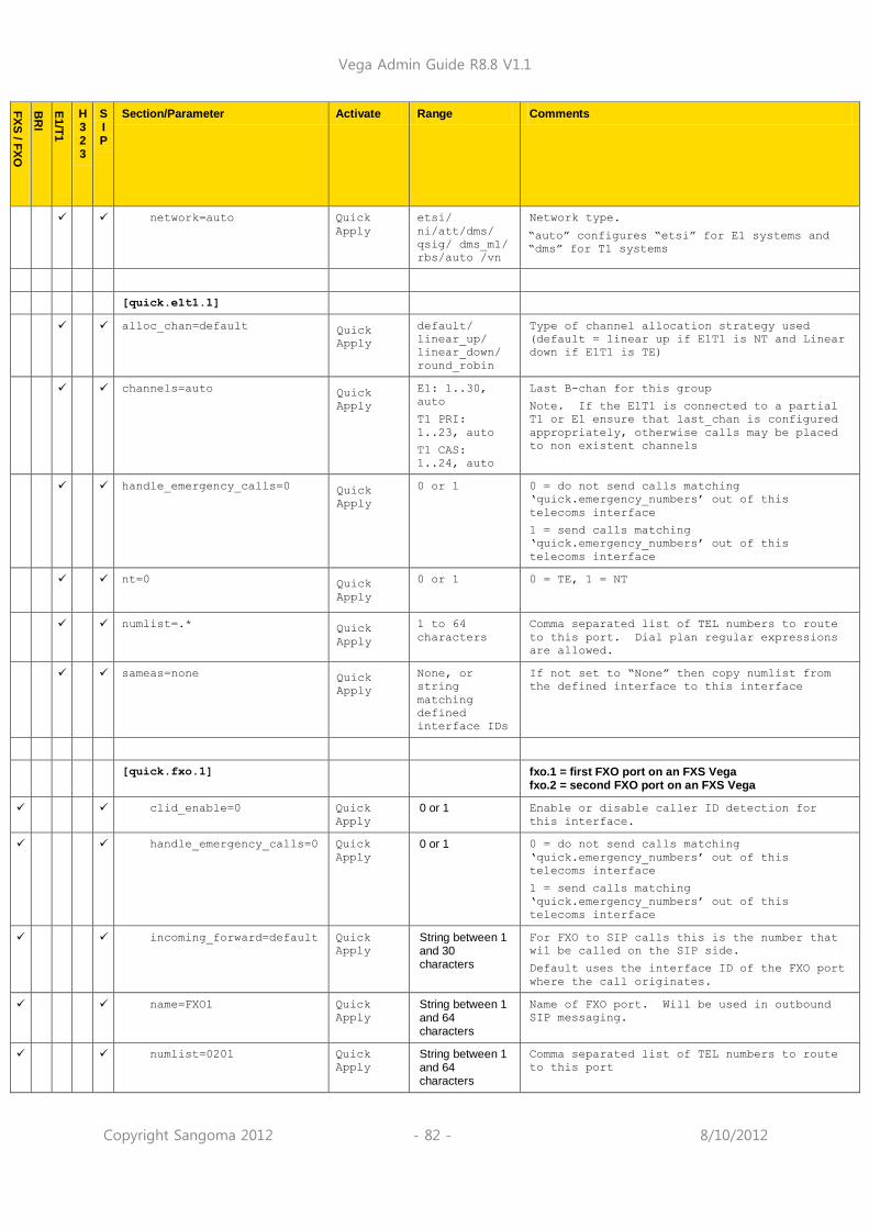
Vega Admin Guide R8.8 V1.1
Copyright Sangoma 2012 - 82 - 8/10/2012
FX
S / F
XO
BR
I
E1/T
1
H 3 2 3
S I P
Section/Parameter Activate Range Comments
network=auto Quick
Apply
etsi/
ni/att/dms/
qsig/ dms_m1/
rbs/auto /vn
Network type.
“auto” configures “etsi” for E1 systems and
“dms” for T1 systems
[quick.e1t1.1]
alloc_chan=default Quick
Apply
default/
linear_up/
linear_down/
round_robin
Type of channel allocation strategy used
(default = linear up if E1T1 is NT and Linear
down if E1T1 is TE)
channels=auto Quick
Apply
E1: 1..30,
auto
T1 PRI:
1..23, auto
T1 CAS:
1..24, auto
Last B-chan for this group
Note. If the E1T1 is connected to a partial
T1 or E1 ensure that last_chan is configured
appropriately, otherwise calls may be placed
to non existent channels
handle_emergency_calls=0 Quick
Apply
0 or 1 0 = do not send calls matching
„quick.emergency_numbers‟ out of this
telecoms interface
1 = send calls matching
„quick.emergency_numbers‟ out of this
telecoms interface
nt=0 Quick
Apply
0 or 1 0 = TE, 1 = NT
numlist=.* Quick
Apply
1 to 64
characters
Comma separated list of TEL numbers to route
to this port. Dial plan regular expressions
are allowed.
sameas=none Quick
Apply
None, or
string
matching
defined
interface IDs
If not set to “None” then copy numlist from
the defined interface to this interface
[quick.fxo.1] fxo.1 = first FXO port on an FXS Vega fxo.2 = second FXO port on an FXS Vega
clid_enable=0 Quick
Apply
0 or 1 Enable or disable caller ID detection for
this interface.
handle_emergency_calls=0 Quick
Apply
0 or 1 0 = do not send calls matching
„quick.emergency_numbers‟ out of this
telecoms interface
1 = send calls matching
„quick.emergency_numbers‟ out of this
telecoms interface
incoming_forward=default Quick
Apply
String between 1 and 30 characters
For FXO to SIP calls this is the number that
wil be called on the SIP side.
Default uses the interface ID of the FXO port
where the call originates.
name=FXO1 Quick
Apply
String between 1 and 64 characters
Name of FXO port. Will be used in outbound
SIP messaging.
numlist=0201 Quick
Apply
String between 1 and 64 characters
Comma separated list of TEL numbers to route
to this port

Vega Admin Guide R8.8 V1.1
Copyright Sangoma 2012 - 83 - 8/10/2012
FX
S / F
XO
BR
I
E1/T
1
H 3 2 3
S I P
Section/Parameter Activate Range Comments
this_tel=0201 Quick
Apply
String between 1 and 30 characters
TELC number to use for calls originating on
this interface if caller ID is not provided.
[quick.fxs]
auth_source=Numeric_ID Quick
Apply
Numeric_ID or Textual_ID or Specified
Field to for SIP authentication challenge
[quick.fxs.1]
auth_pwd=auth_password Quick
Apply
String between 1 and 64 characters
Password to use when challenge for SIP
authentication is received. Only used when
quick registration type is set to FXS Port
auth_username=default Quick
Apply
String between 1 and 64 characters
Username to use when challenge for SIP
authentication is received. Only used when
quick registration type is set to FXS Port
clid_enable=0 Quick
Apply
0 or 1 Enable or disable caller ID generation for
this interface.
enable=1 Quick
Apply
0 or 1 Enable or disable this interface
name=FXS1 Quick
Apply
String between 1 and 64 characters
Name of FXS port. Will be used in outbound
SIP messaging.
numlist=0101 Quick
Apply
String between 1 and 64 characters
Comma separated list of TEL numbers to route
to this port
this_tel=0101 Quick
Apply
String between 1 and 30 characters
Numeric ID of this port. Will be used in
outbound SIP messaging.
[quick.lan]
dhcp=1 Quick
Apply
0 or 1
dns1=0.0.0.0 Quick
Apply
IP address in form www.xxx.yyy.zzz
IP address of DNS server
dns1=0.0.0.0 Quick
Apply
IP address in form www.xxx.yyy.zzz
IP address of DNS server
duplex=full Quick
Apply
half or full Full: Full duplex mode to be used on the LAN
if other end supports it
Half: Half duplex mode will be used
gateway=0.0.0.0 Quick
Apply
IP address in form www.xxx.yyy.zzz
IP address of default gateway
ip=0.0.0.0 Quick
Apply
IP address in form www.xxx.yyy.zzz
IP address of Vega
media priority=0 Quick
Apply
0 to 7 media_priority is used for media packets, ie
audio RTP packets and T.38 packets
ntp=0.0.0.0 Quick String between 1 IP address of NTP server

Vega Admin Guide R8.8 V1.1
Copyright Sangoma 2012 - 84 - 8/10/2012
FX
S / F
XO
BR
I
E1/T
1
H 3 2 3
S I P
Section/Parameter Activate Range Comments
Apply and 64 characters
physpeed=Auto Quick
Apply
Auto or 10BASE-T or 100BASE-TX
Fix speed at either 10 or 100mbps. Auto will
match speed to other end.
subnet=255.255.255.0 Quick
Apply
IP address in form www.xxx.yyy.zzz
Subnet for local network
tos_diff=0 Quick
Apply
0 to 4094 Priority to use for packets sent out on LAN
interface
vlan_id=0 Quick
Apply
0 to 4095 VLAN ID for all packets sent out using this
LAN interface
8021q=0 Quick
Apply
0 or 1 Enable 8021q packet tagging.
[quick.voip]
reg_type=off Quick
Apply
Off or Gateway or FXS Port
Off: No SIP registration requests will be
sent.
Gateway: A single SIP registration request
will be sent per gateway.
FXS Port: One SIP registration request will
be sent for each FXS port…
useproxy=1 Quick
Apply
0 or 1 0: Gateway is configured to send all SIP
calls to a single SIP device.
1: Calls will be routed to different SIP
devices depending on called number.
useoutbound=No Quick
Apply
Yes or No No: No outbound proxy will be used. SIP
requests will be sent directly to relevant
SIP device.
1: Outbound proxy will be used. SIP requests
will be sent outbound proxy address.
[quick.voip.endpoint.1]
ip=0.0.0.0 Quick
Apply
IP address in form www.xxx.yyy.zzz
IP address used for call routing. Only used
when quick.voip.use_proxy=0
numlist=list of numbers Quick
Apply
String between 1 and 64 characters
List of numbers terminating on this VoIP
endpoint. Only used when
quick.voip.use_proxy=0
[quick.voip.proxy]
auth_name=Reg and Auth ID Quick
Apply
String between 1 and 64 characters
Authentication ID for “gateway registration”.
Only used when quick.voip.reg_type=Gateway
auth_pwd=Reg and Auth
Password
Quick
Apply
String between 1 and 64 characters
Authentication password for “gateway
registration”. Only used when
quick.voip.reg_type=Gateway
outbound_proxy_addr=0.0.0.0
Quick
Apply
String between 1 and 64 characters
IP address for first SIP hop.
proxy_addr=default- Quick String between 1 and 64
IP address for SIP proxy.

Vega Admin Guide R8.8 V1.1
Copyright Sangoma 2012 - 85 - 8/10/2012
FX
S / F
XO
BR
I
E1/T
1
H 3 2 3
S I P
Section/Parameter Activate Range Comments
proxy-1.com Apply characters
proxy_domain_name=default-
reg-domain.com
Quick
Apply
String between 1 and 255 characters
SIP domain used for calls.
[rs232.1]
baud_rate=115200 S/R 9600 / 19220
/ 38400 /
57600 /
115200
Baud rate to use for specified console port
data_bits=8 S/R 8 Data bits to use for specified console port
flow_control=xonoff S/R none /
xonxoff /
hardware
Flow control type to use for specified
console port
parity=none S/R odd / even /
mark / space
/ none
Parity bits to use for specified console port
stop_bits=1 S/R 1 / 1.5 / 2 Stop bits to use for specified console port
[serviceprofile]
[serviceprofile.1] H.450 supplementary service section (up to 10
entries can be supported)
name=default CALL length<32 Name of this service profile – for self
documentation purposes
transfer=1 CALL 0 or 1 0 = do not support call transfer, 1 =
support call transfer
Divert=1 CALL 0 or 1 0 = do not support call diversion, 1 =
support call diversion
transfer_caller_id=transferr
ed_party
CALL transferring_
party
transferred_p
arty
When a transferred call is passed to the
Vega, the Vega has a choice of two caller ids
that it can pass on – the caller id of the
transferring party or the caller id of the
party being transferred.
[sip]
T1=2000 APPLY 1 to 5000 T1 is the value of the first SIP timeout of a
new message. For every SIP message
retransmission the previous SIP timeout is
doubled. (Up to 5 retries are attempted for
PRACK and INVITE, and up to 10 retries for
other methods). If no response is received
after all the retries the Vega will send a
CANCEL (with retries if it is not
acknowledged).
In the case of an INVITE, if a 100 trying is
received a new timer of value 64 * T1 is
started. If no 180 ringing (or other message
>180) is received within this time then the
Vega will send a CANCEL (with retries if it
is not acknowledged).
Note also interactions with multiple proxies

Vega Admin Guide R8.8 V1.1
Copyright Sangoma 2012 - 86 - 8/10/2012
FX
S / F
XO
BR
I
E1/T
1
H 3 2 3
S I P
Section/Parameter Activate Range Comments
– see section 16.4.1.1 “Multiple SIP Proxy
Support”
T2=4000 APPLY 1 to 40000 T2 limits the maximum SIP retry timeout; if
T1*2^n > T2, then the timeout limits to T2.
accept_non_proxy_invites=0 APPLY 0
1
0 = Only allow SIP INVITES from the SIP Proxy
(or backup proxies)
1 = Accept SIP INVITES from any SIP device
accessibility_check_interval
=30
APPLY 10 to 600 Interval in seconds between transmission of
SIP messages to check proxy and registrar
availability
allow_sip_uri=1 APPLY 0, 1 0 = Only allow calls to proceed with a SIPS
URI (secure SIP)
1 = Allow calls with either a SIPS or SIP URI
default_uri_scheme=sip sip or sips Use SIP or SIPS URI scheme
… if sips is chosen, ensure that
sip.sig_transport=tls (otherwise Vega will
revert to sip mode)
enable_modem=1 APPLY 0 or 1 0 = treat fax and low speed modem calls as
fax calls
1 = low speed modem calls use G.711 up-
speding unless V21 tone is heard, in which
case call is handled as a fax call
fax_detect=terminating APPLY terminating,
always, never
terminating: Vega only monitors for fax tones
on calls made out of its telephony interface.
(The dialled fax machine is the fax machine
that will initiate the fax tones)
always: Vega monitors for fax tones on calls
from both telephony and LAN interfaces
never: Vega does not monitor for fax tones
incoming_cause_mapping_index
=0
APPLY Index Cause code mapping entry to use from
_advanced.incoming_cause_mapping to map
incoming cause codes from this SIP interface
lan_profile=1 0 to 10 Lan profile to use for SIP calls
local_rx_port=5060 APPLY 1 to 65535 IP Port number to receive SIP messages on
max_calls Default value
depends on hardware.
S/R E1: 1..120
T1: 1..96
Vega 50: 1..10
Vega 5000:
1..48
Maximum allowable calls in progress
(call clears with cause code 34 if max calls
is exceeded)
media_control_profile=0 0..10 Define which media control profile (x) to use
in media.control.x.dynamic_update
modem_detect=terminating APPLY terminating,
always, never
terminating: Vega only monitors for modem
tones on calls made out of its telephony
interface. (The dialled modem is the modem
that will initiate the modem tones)
always: Vega monitors for modem tones on
calls from both telephony and LAN interfaces
never: Vega does not monitor for modem tones
outgoing_cause_mapping_index
=0
APPLY Index Cause code mapping entry to use from
_advanced.outgoing_cause_mapping to map
outgoing cause codes from this SIP interface
reg_enable=0 APPLY 0 or 1 Disable / enable SIP registration

Vega Admin Guide R8.8 V1.1
Copyright Sangoma 2012 - 87 - 8/10/2012
FX
S / F
XO
BR
I
E1/T
1
H 3 2 3
S I P
Section/Parameter Activate Range Comments
reg_mopde=normal APPLY normal or
on_ISDN_activ
e
Normal: SIP registration requests will be
sent whenever configured
on_ISDN_active: SIP registration requests
will only be sent when ISDN interfaces become
active (useful for E1T1 ByPass relays).
reg_on_startup=1 S/R 0
1
Register on first call to that port
Register on power up or re-boot
sess_timer_index=1 1 to 3 Select session timer profile to use
sig_transport=udp udp, tcp, tls Transport protocol for SIP messaging, UDP,
TCP or TLS.
signalling_app_id=none APPLY alpha numeric
string 1..40
chars
Signalling Application ID – part of the SIP
info message header
T38_annexe_accept=0 0 or 1 1: Vega will accept T38 Annex E requests in
incoming SIP INVITE messages, allowing
switching between voice and T.38 without a
re-INVITE, RTP media can be changed on the
fly
T38_annexe_use=0 0 or 1 1: Vega will offer T38 Annex E in outgoing
SIP INVITE messages (offers both T.38 and a
voice codec in the sdp offer allowing
switching between voice and T.38 without a
re-INVITE, RTP media can be changed on the
fly)
[sip.auth.user]
[sip.auth.user.1] First of up to 20 authentication users
enable=0 APPLY 0 or 1 Enable this user authentication username /
password combination
password=pass1 APPLY Up to 31
characters
Password
resource_priority=routine As specified
in the
currently
active
NameSpace
list
Resource-Priority to specify for calls made
to SIP by this user
sip_profile=1 1 .. 5 SIP profile to use for this authentication
user
subscriber=IF:0101 APPLY Up to 63
characters
(IF: and
TELC:)
This authentication is used on calls which
are associated with this / these telephone
interfaces / telephone numbers
username=authuser1 APPLY Up to 31
characters
Username is used as the <body> of the
authentication username;
authentication username = <body>
[sip.hold]
mode=silence silence or
sipping_servi
ce_11
silence = silence on hold
sipping_service_11 = Music on hold using the
draft-ietf-sipping-service-examples-11 method

Vega Admin Guide R8.8 V1.1
Copyright Sangoma 2012 - 88 - 8/10/2012
FX
S / F
XO
BR
I
E1/T
1
H 3 2 3
S I P
Section/Parameter Activate Range Comments
[sip.hold.music_service.1] 1st of only 1 music_service profile
ipname=0.0.0.0 IP address or DNS resolvable name of the
music on hold server not DNS
port=5060 IP port number of the music on hold server
uri=NULL URI to present to the music on hold server to
get MoH, [email protected]:5061
[sip.profile.1] 1st of up to 5 SIP profiles
alt_domain=alt-reg-
domain.com
APPLY length<32
length<256
Alternate public domain to use in SIP INVITE
headers )
Select to use alt_domain rather than
reg_domain, choose the appropriate value in
_advanced.sip.from_header_host and
_advanced.sip.to_header_host
capset=2 1 .. 30 Codec capability set to use for SIP calls for
this SIP profile
dtmf_info=mode1 APPLY mode1 or
mode2
mode1: Vega format INFO messages for out of
band DTMF
mode2: Cisco format INFO messages for out of
band DTMF
dtmf_transport=rfc2833 APPLY rfc2833
info
rfc2833_txinf
o
rfc2833_rxinf
o
Use RFC2833 method for communicating out of
band DTMF
Use INFO messages for communicating out of
band DTMF
Transmit out of band DTMF both as RFC2833
messages and INFO messages (on receive, only
action RFC2833 out of band DTMF messages)
Transmit out of band DTMF both as RFC2833 and
action both RFC2833 and INFO DTMF messages –
be careful using this mode, if both INFO and
RFC2833 messages are recived for a single
tone, the Vega will action both the RFC2833
and the INFO request, and so douple tones
will be played.
N.B. Out Of Band DTMF must be configured for
each relevant codec in order to transfer DTMF
as info or RFC2833 messages.
from_header_host=reg_domain
APPLY ipname/
reg_domain/
alt_domain
outgoing INVITE uses ipname / sip.reg_domain
/ alt_domain in SIP From: header
from_header_userinfo=calling
_party
calling_party
or
auth_username
calling_party: in an outgoing INVITE calling
party number is used in the From: header
before the @
auth_username: in an outgoing INVITE
authentication username is used in the
From: header before the @
interface=9901 S/R length<32 Interface ID of SIP interface
name=profile1 APPLY length<32 Name of this SIP profile – for self
documentation purposes
redirect_host=reg_domain APPLY reg_domain or
alt_domain
For redirected calls use either reg_domain or
alt_domain for SIP headers in new call.
reg_domain=default-reg-
domain.com
APPLY length<32
length<256
Public domain to use in SIP INVITE headers
To use reg_domain rather than alt_domain,
choose the appropriate value in

Vega Admin Guide R8.8 V1.1
Copyright Sangoma 2012 - 89 - 8/10/2012
FX
S / F
XO
BR
I
E1/T
1
H 3 2 3
S I P
Section/Parameter Activate Range Comments
_advanced.sip.from_header_host and
_advanced.sip.to_header_host
reg_expiry=600 APPLY 1 to 10000 Lifetime of registration (ms) (before re-
registration attempted). Minimum time Vega
actions is 10 seconds
reg_req_uri_port=5060 S/R 0 to 65535 1..65535: port number to be used in the
request URI of Registration requests. This is
separately configurable from the
reg_remote_rx_port (the port that the
Registration messages are sent to) so that in
cases where an outbound proxy is being used,
the destination port in the URI can be
different from the port of the outbound proxy
0: no port will appear in the request URI
req_uri_port=5060 S/R 0 to 65535 1..65535: port number to be used in the
request URI of Vega initiated SIP calls. This
is separately configurable from the
remote_rx_port (the port that the SIP
messages are sent to) so that in cases where
an outbound proxy is being used, the
destination port in the URI can be different
from the port of the outbound proxy
0: no port will appear in the request URI
rfc2833_payload=101 APPLY 96 to 127 Alters the payload field in the RTP message
that carries the rfc2833 data; valid values
for rfc2833 data are 96 to 127. (A Vega
receiving a call will always use the value
provided by the calling party sdp). Some
devices, like Cisco units need the
rfc2833_payload to match at both ends – e.g.
Cisco config
> rtp payload-type nte 96
> dtmf-relay rtp-nte
sig_transport=udp S/R udp / tcp /
tls
Signalling transport to use for SIP messages,
UDP, TCP or TLS.
mode=off off,
supported,
require,
require_rfc45
68
off: SRTP not used (initiated or accepted)
supported: uses "RTP/AVP" in "m=" line and
adds the "a=crypto:" line.
It interops with non-SRTP UAs (i.e. only best-
effort to use SRTP)
require: uses "RTP/AVP" in "m=" line and adds
the "a=crypto:" line
Requires that remote endpoint has the
"a=crypto:" line
require_rfc4568: as „require‟ but uses
"RTP/SAVP" in "m=" line
auth_bits_default=80 32 or 80 32: Request 32 bit authentication in any
initiated INVITE
80: Request 80 bit authentication in any
initiated INVITE
auth_bits_min=32 32 or 80 32: Min authentication level accepted (where
encryption is used) is 32 bit authentication
80: Min authentication level accepted (where
encryption is used) is 80 bit authentication
to_header_host=reg_domain
APPLY ipname/
reg_domain/
alt_domain
outgoing INVITE uses ipname / sip.reg_domain
/ alt_domain in SIP To: header and in SIP URI
[sip.profile.1.proxy]
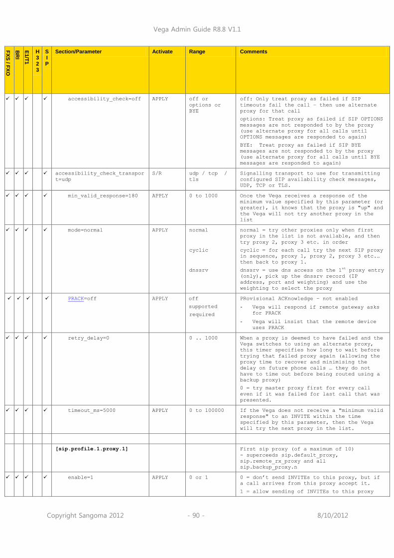
Vega Admin Guide R8.8 V1.1
Copyright Sangoma 2012 - 90 - 8/10/2012
FX
S / F
XO
BR
I
E1/T
1
H 3 2 3
S I P
Section/Parameter Activate Range Comments
accessibility_check=off APPLY off or
options or
BYE
off: Only treat proxy as failed if SIP
timeouts fail the call – then use alternate
proxy for that call
options: Treat proxy as failed if SIP OPTIONS
messages are not responded to by the proxy
(use alternate proxy for all calls until
OPTIONS messages are responded to again)
BYE: Treat proxy as failed if SIP BYE
messages are not responded to by the proxy
(use alternate proxy for all calls until BYE
messages are responded to again)
accessibility_check_transpor
t=udp
S/R udp / tcp /
tls
Signalling transport to use for transmitting
configured SIP availability check messages,
UDP, TCP or TLS.
min_valid_response=180 APPLY 0 to 1000 Once the Vega receives a response of the
minimum value specified by this parameter (or
greater), it knows that the proxy is "up" and
the Vega will not try another proxy in the
list
mode=normal APPLY normal
cyclic
dnssrv
normal = try other proxies only when first
proxy in the list is not available, and then
try proxy 2, proxy 3 etc. in order
cyclic = for each call try the next SIP proxy
in sequence, proxy 1, proxy 2, proxy 3 etc.…
then back to proxy 1.
dnssrv = use dns access on the 1st proxy entry
(only), pick up the dnssrv record (IP
address, port and weighting) and use the
weighting to select the proxy
PRACK=off APPLY off
supported
required
PRovisional ACKnowledge – not enabled
- Vega will respond if remote gateway asks
for PRACK
- Vega will insist that the remote device
uses PRACK
retry_delay=0 0 .. 1000 When a proxy is deemed to have failed and the
Vega switches to using an alternate proxy,
this timer specifies how long to wait before
trying that failed proxy again (allowing the
proxy time to recover and minimising the
delay on future phone calls … they do not
have to time out before being routed using a
backup proxy)
0 = try master proxy first for every call
even if it was failed for last call that was
presented.
timeout_ms=5000 APPLY 0 to 100000 If the Vega does not receive a "minimum valid
response" to an INVITE within the time
specified by this parameter, then the Vega
will try the next proxy in the list.
[sip.profile.1.proxy.1] First sip proxy (of a maximum of 10)
- superceeds sip.default_proxy,
sip.remote_rx_proxy and all
sip.backup_proxy.n
enable=1 APPLY 0 or 1 0 = don‟t send INVITEs to this proxy, but if
a call arrives from this proxy accept it.
1 = allow sending of INVITEs to this proxy

Vega Admin Guide R8.8 V1.1
Copyright Sangoma 2012 - 91 - 8/10/2012
FX
S / F
XO
BR
I
E1/T
1
H 3 2 3
S I P
Section/Parameter Activate Range Comments
ipname=default-proxy-
1.com
APPLY Up to 32
characters
The IP address or resolvable DNS name of the
proxy
port=5060 APPLY 1 to 65535 IP port to use to access this proxy (not used
when mode = dnssrv as dnssrv supplies IP
port)
tls_port=5061 1 to 65535 Port to send TLS traffic to
[sip.profile.1.registrar]
accessibility_check=off APPLY off or
options
off: Only treat registrar as failed if SIP
timeouts fail the registration – then use
alternate registrar for that registration
options: Treat registrar as failed if SIP
OPTIONS messages are not responded to by the
registrar (use alternate registrar for all
registratins until OPTIONS messages are
responded to again)
accessibility_check_transpor
t=udp
S/R udp / tcp /
tls
Signalling transport to use for transmitting
configured SIP availability check messages,
UDP, TCP or TLS.
max_registrars=3 Maximum number of Registrars that the Vega
will search [in this profile] in order to
find a Registrar that will respond with a
„success‟ response.
min_valid_response=200 APPLY 0 to 1000 Minimum SIP response value that indicates a
successful response from the Registrar
mode=normal APPLY normal
dnssrv
normal = try next registrar only when
previous registrar does not provide a
„success‟ response.
dnssrv = use dns access on the 1st registrar
entry (only), pick up the dnssrv record (IP
address, port and weighting) and use the
weighting to select the registrar
retry_delay=0 0 .. 1000 When a registrar is deemed to have failed and
the Vega switches to using an alternate
registrar, this timer specifies how long to
wait before trying that failed registrar
again (allowing it time to recover).
0 = try master proxy first for every call
even if it was failed for last call that was
presented.
timeout_ms=5000 Timeout in milliseconds to wait for a
response from each Registar
[sip.profile.1.registrar.1]
enable=0 APPLY 0 or 1 1 = enable this registrar to be used [in this
profile] by the Vega
ipname=default-
registrar-1.com
APPLY Up to 32
characters
The IP address or resolvable DNS name of the
registrar
port=5060 APPLY 1 to 65535 IP port to use to access this registrar (not
used when mode = dnssrv as dnssrv supplies IP
port)
tls_port=5061 1 to 65535 Port to send TLS registrations to

Vega Admin Guide R8.8 V1.1
Copyright Sangoma 2012 - 92 - 8/10/2012
FX
S / F
XO
BR
I
E1/T
1
H 3 2 3
S I P
Section/Parameter Activate Range Comments
[sip.reg.user.1] Sip registration parameters
- first of up to 16 entries
auth_user_index=1 APPLY 1 to 100 Authentication parameters to use if SIP
authentication is demanded (see
sip.auth.user.n)
contact_suffix=NULL APPLY String 1 to
127
characters
Suffix that will be added to the Contact
header for SIP REGISTER requests sent for
this user.
dn Default varies
depending on hardware
APPLY Up to 31
characters Dn specifies the nn in the SIP registration
contact address nn@ip_address_of_vega
enable=0 APPLY 0 or 1 Enable these registration details
sip_profile=1 APPLY 1 .. 5 SIP profile to use for this registration user
username=01 APPLY Up to 31
characters
Username is used as the <body> of the
registration username;
registration username = <body>
[sip.remote_admin] Remote admin (authentication) details
realm=default_realm Up to 63
characters Realm for Vega initiated authentication
[sip.remote_admin.1] Remote admin user (authentication) details
- first of up to 3 entries
enable=0 0 or 1 Enable this authentication user
password=default Up to 63
characters Password for Vega initiated authentication
(note authentication will always fail if this
is not changed from the value „default‟)
Username=default Up to 63
characters Username for Vega initiated authentication
(note authentication will always fail if this
is not changed from the value „default‟)
[sip.sess_timer.1] First of up to 3 session timer profiles;
Active session timer profile defined by
sip.session_timer_index
See RFC 4028 for full details on Session
Timers
enable=0 0 or 1 1 = enable this session timer
interval=1800 120 .. 7200 Preferred time interval Vega will negotiate
with far end for checking continued
connection of the call (in seconds)– uses a
re-INVITE, and checks that it receives a
response.
min_interval=300 120 .. 7200 Minimum time interval Vega will negotiate
with far end for checking continued
connection of the call (in seconds).
refresher_pref=remote local or
remote
local: this Vega will initiate Session Timer
re-invites
remote: destination device is requested to
initiate Session Timer re-invites
[sip.tls]

Vega Admin Guide R8.8 V1.1
Copyright Sangoma 2012 - 93 - 8/10/2012
FX
S / F
XO
BR
I
E1/T
1
H 3 2 3
S I P
Section/Parameter Activate Range Comments
local_rx_port=5061 S/R 1 to 65535 Local listening port for SIP TLS traffic
[sipproxy] See also ‘IN_41-Vega Resilience Proxy’ on
www.wiki.sangoma.com/vega
itsp_register_path=auto APPLY auto / off /
rewrite_conta
ct /
require_path
auto - tries Path first but if Path headers
aren't refelected or get "420 Bad
Extension" (path not supported) then note
down the IP of the failed registrar. Next
time the REGISTER comes in,it will use the
"rewrite contact" mechanism for the failed
registrar.
off - behaves as now.
rewrite_contact – modify the Contact header
in the REGISTER request so it contains the
IP of the ENP
path_required - ENP adds the Path header - if
the registrar understands it, it will
reflect the Path back and will use the Path
as a Route to the registering UA (see RFC
3327, sections 5.5.1 and 5.5.2 for usage
examples)
mode=off APPLY standalone_pr
oxy,
forward_to_it
sp,
itsp_trunk or
off
standalone_proxy: No forwarding of SIP
messages to the ITSP occurs – all
registrations and routing are handled by
the resilience proxy
forward to ITSP: Normal ITSP resilience mode
itsp_trunk: Calls to registered devices are
sent directly to the endpoints, calls to
non-registered destinations are forwarded
to the ITSP
off: Resilience proxy is disabled
realm=abcdefghijwhatever.com
APPLY 1 to 127
characters
Realm (domain) of ITSP proxy
rx_port=6060 S/R 1 to 65535 IP Port on which Resilience proxy listens for
requests
tls_rx_port=6061 S/R 1 to 65535 IP Port on which Resilience proxy listens for
SIP TLS requests
[sipproxy.auth.user]
use_aliases=if_itsp_down APPLY always,
if_itsp_down,
never
always: always check for aliases
if_itsp_down: check for aliases when in ITSP
Down mode
never: never handle aliases
[sipproxy.auth.user.1] (Entries are not needed here if allowed
device is in a trusted IP address range)
aliases=NULL APPLY NULL or up to
three comma
separated
aliases, each
up to 80
chars
NULL: no alias defined
Aliases: can contain up to 3 comma separated
aliases. Each alias can be up to 80
characters, and each can include regular
expressions.
enable=0 APPLY 0 or 1 Enable this set of authentication entries

Vega Admin Guide R8.8 V1.1
Copyright Sangoma 2012 - 94 - 8/10/2012
FX
S / F
XO
BR
I
E1/T
1
H 3 2 3
S I P
Section/Parameter Activate Range Comments
username=user APPLY 1 to 63
characters
Authentication user name (same as
registration user name)
password=pass APPLY 1 to 63
characters
Authentication password to register with
Resilience Proxy
[sipproxy.fallback_pstn_gw.p
lan]
gw_list=all APPLY 1 to 31
characters
Comma separated list of trunk gateways that
can be used in the event that PSTN fallback
is required
redirection_responses=500-
599
APPLY 1 to 63
characters
Range of SIP responses that result in trying
the next gateway in the list. If a SIP
response outside this range is received the
call will be dropped.
routing_rule=linear_up APPLY 1 to 31
characters
Specifies how the gateways in the list will
be tried.
[sipproxy.ignore.1]
enable=0 APPLY 0 or 1 Enable this „ignore‟ entry
ipmax=0.0.0.0 APPLY IP address or
DNS hostname
Upper range of IP address values to ignore
SIP messaging from (provide no response)
ipmin=0.0.0.0 APPLY IP address or
DNS hostname
Lower range of IP address values to ignore
SIP messaging from (provide no response)
[sipproxy.itsp_nat]
rport=0 APPLY 0 or 1 If set to 1, Vega will insert the rport
parameter into the Via header of SIP
messages.
[sipproxy.itsp_proxy]
accessibility_check=options
APPLY off or
options
off: Only treat ITSP Proxy as failed if SIP
timeouts fail the call – then use alternate
resilience proxy functionality for that call
[this setting is NOT RECOMMENDED]
options: Treat ITSP proxy as failed if SIP
OPTIONS messages are not responded to by the
ITSP proxy (use resilience proxy for all
calls until OPTIONS messages are responded to
again)
accessibility_check_transpor
t=udp
S/R udp / tcp Signalling transport to use for transmitting
configured SIP availability check messages,
UDP or TCP.
mode=normal normal,
cyclic,
dnssrv
Normal: sipproxy.itsp_proxy.1 is used, unless
it is not available, then .2, then .3 etc.
Cyclic: basic load sharing; .1 is used for
first call, .2 for second, .3 for 3rd looping
to use the next enabled proxy for each
subsequent call.
Dnssrv: use the dnssrv entry of
sipproxy.itsp_proxy.1.ipname to define the
proxies to send calls to and their relevant
weightings.

Vega Admin Guide R8.8 V1.1
Copyright Sangoma 2012 - 95 - 8/10/2012
FX
S / F
XO
BR
I
E1/T
1
H 3 2 3
S I P
Section/Parameter Activate Range Comments
redirection_responses=500-
599
APPLY String 1 to
63 characters
Range of SIP responses that will mean the
next proxy in the proxy list is attempted for
a given call
sig_transport=udp S/R udp / tcp Signalling transport to use for transmitting
SIP messages to this proxy, UDP or TCP.
[sipproxy.itsp_proxy.1]
enable=0 APPLY 0 or 1 Enable this ITSP‟s proxy details
ipname=0.0.0.0 APPLY IP address or
DNS hostname
IP address or DNS hostname of the proxy
port=5060 APPLY 0 to 65535 IP port number of the ITSP‟s proxy. This is
the port to which SIP requests will be sent.
tls_port=5061 APPLY 0 to 65535 TLS IP port number of the ITSP‟s proxy. This
is the port to which SIP TLS requests will be
sent.
[sipproxy.reject.1]
enable=0 APPLY 0 or 1 Enable this „reject‟ entry
ipmax=0.0.0.0 APPLY IP address or
DNS hostname
Upper range of IP address values to actively
reject SIP messaging from
ipmin=0.0.0.0 APPLY IP address or
DNS hostname
Lower range of IP address values to actively
reject SIP messaging from
[sipproxy.trunk_gw]
accessibility_check=options APPLY off or
options
off: Only treat ITSP Proxy as failed if SIP
timeouts fail the call – then use alternate
resilience proxy functionality for that call
[this setting is NOT RECOMMENDED]
options: Treat ITSP proxy as failed if SIP
OPTIONS messages are not responded to by the
ITSP proxy (use resilience proxy for all
calls until OPTIONS messages are responded to
again)
accessibility_check_transpor
t=udp
S/R udp / tcp Signalling transport to use for transmitting
configured SIP availability check messages,
UDP or TCP.
allow_itsp_calls_to_pstn=nev
er
APPLY never or
always
never: Calls that originate from the ITSP
will not be routed to trunk gateways tagged
as PSTN gateways
always: Allow calls to route from ITSP to
trunk gateways that are tagged as PSTN
gateways
from_action=trust APPLY trust or auth
or reject or
ignore
trust: Calls from trunk gateways will be
treated as trusted
reject: Calls from trunk gateways will be
actively rejected
ignore: Calls from trunk gateways will be
ignored (no response will be sent)
mode=normal APPLY normal or
cyclic or
dnssrv
Normal: trunk gateway 1 is used, unless it is
not available, then 2, then 3 etc.
Cyclic: basic load sharing; trunk gateway 1
is used for first call, 2 for second, 3 for

Vega Admin Guide R8.8 V1.1
Copyright Sangoma 2012 - 96 - 8/10/2012
FX
S / F
XO
BR
I
E1/T
1
H 3 2 3
S I P
Section/Parameter Activate Range Comments
3rd looping to use the next enabled proxy for
each subsequent call.
Dnssrv: use the dnssrv entry of
sipproxy.trunk_gw.1.ipname to define the
proxies to send calls to and their relevant
weightings.
sig_transport=udp S/R udp / tcp Signalling transport to use for transmitting
SIP messages to this trunk gateway, UDP or
TCP.
[sipproxy.trunk_gw.forward_t
o_itsp_mode]
allow_local_trunk_calls_to_i
tsp=never
APPLY never or
always
never: Calls that originate from trunk
gateways will not be routed to the ITSP
always: Calls that originate from trunk
gateways can be routed to the ITSP
allow_pstn_calls_to_itsp=nev
er
APPLY never or
always
never: Calls that originate from trunk
gateways tagged as PSTN will not be routed to
the ITSP
always: Calls that originate from trunk
gateways tagged as PSTNcan be routed to the
ITSP
[sipproxy.trunk_gw.plan.1]
dest=TEL:911 APPLY String 1 to
128
characters
Routing rule that cause calls that match to
route to 1 or more of the trunk gateways
defined in this group
enable=0 APPLY 0 or 1 Enable or disable this trunk gateway routing
plan
gw_list=1 APPLY String 1 to
31 characters
Specify a comma separated list of trunk
gateway indices that will be used for this
routing plan
name=emergency APPLY String 1 to
31 characters
Name of plan for self documentation purposes
only
redirection_responses=500-
599
APPLY String 1 to
63 characters
Range of SIP responses that will mean the
next trunk gateway in the list is attempted
for a given call
routing_rule=linear_up APPLY String 1 to
31 characters
linear_up: trunk gateway 1 is used, unless it
is not available, then 2, then 3 etc.
round_robin: basic load sharing; trunk
gateway 1 is used for first call, 2 for
second, 3 for 3rd looping to use the next
enabled proxy for each subsequent call.
Dnssrv: use the dnssrv entry of
sipproxy.trunk_gw.1.ipname to define the
proxies to send calls to and their relevant
weightings.
[sipproxy.trunk_gw.1]
enable=1 APPLY 0 or 1 Enable or disable this trunk gateway
ipname=trunk_gateway_at_127.
0.0.1
APPLY Readonly
(not readonly
for higher
indices)
IP address or name of trunk gateway

Vega Admin Guide R8.8 V1.1
Copyright Sangoma 2012 - 97 - 8/10/2012
FX
S / F
XO
BR
I
E1/T
1
H 3 2 3
S I P
Section/Parameter Activate Range Comments
is_pstn_gw=1 APPLY 0 or 1 Tag this trunk gateway as having access to
PSTN. This will affect the allowed routing
port=0 APPLY Readonly
(not readonly
for higher
indices)
Far-end IP port that will be the destination
for transmitted SIP messages
tls_port=0 APPLY Readonly
(not readonly
for higher
indices)
Far-end IP port that will be the destination
for transmitted SIP TLS messages
[sipproxy.trust]
disable_all=0 APPLY 0 or 1 0: Respect entries in SIPPROXY trust table
1: Disable all entries in SIPPROXY trust
table
[sipproxy.trust.1]
enable=0 APPLY 0 or 1 Enable this „trust‟ entry
ipmax=0.0.0.0 APPLY IP address or
DNS hostname
Upper range of IP address values to trust SIP
messaging from (don‟t demand authentication)
ipmin=0.0.0.0 APPLY IP address or
DNS hostname
Lower range of IP address values to trust SIP
messaging from (don‟t demand authentication)
[smtp]
domain=abcdefghijwhatever.co
m
For engineering use only
ip=0.0.0.0 For engineering use only
lan_profile=1 For engineering use only
port=25 For engineering use only
[snmp]
lan_profile=1 S/R 0 .. 10 Lan profile to use for SNMP
[snmp.mib2.communities.1]
name=public APPLY String 1 to
16 characters
Community name (referenced by
snmp.mib2.managers.x.community)
get=1 APPLY 0 or 1 1 = allow members of this community to read
MIBs
set=1 APPLY 0 or 1 1 = allow members of this community to set
values via SNMP
traps=1 APPLY 0 or 1 1 = enable traps to be sent to members of this
community
[snmp.mib2.managers.1] List of who is allowed to manage this Vega
community=public APPLY String 1 to
16 characters
Manager‟s community (one of the
snmp.mib2.communities.x.name)

Vega Admin Guide R8.8 V1.1
Copyright Sangoma 2012 - 98 - 8/10/2012
FX
S / F
XO
BR
I
E1/T
1
H 3 2 3
S I P
Section/Parameter Activate Range Comments
ip=0.0.0.0 APPLY String 1 to
24 characters
Manager‟s IP address
subnet=255.255.255.0 APPLY String 1 to
24 characters
Mask to identify significant part of manager‟s
ip address to check
support_snmpv3=1 APPLY 0 or 1 0 = enable SNMP V1 support
1 = enable SNMP V3 support
[snmp.mib2.system]
auth_pwd=authpassword APPLY String 1 to
64 characters
SysContact=abcdefghijwhateve
r.com
APPLY String 1 to
256
characters
Contact name for this device (to populate MIB)
sysLocation=PlanetEarth APPLY String 1 to
256
characters
Location of this device (to populate MIB)
[ssh]
port=22 P,IMM 1 to 65535 IP port number for SSH
[suppserv]
enable=0 IMM 0 or 1 Enable supplementary services (on FXS ports)
[suppserv.profile.1] See also “IN_27 FXS Call transfer”
call_conference_mode=cmd_mod
e
APPLY cmd_mode /
simple
Simple = conference will take place on next
flash hook. Cmd_mode = conference will be
initiated with feature code
call_waiting=cmd_mode APPLY cmd_mode /
simple
Simple = switch between calls using flash
hook. Cmd_mode = switch will be initiated with
feature code
call_waiting_hangup=hangup_a
ll
APPLY Hangup_all /
hangup_curren
t_and_ringbac
k
Controls the behaviour of calls in call
waiting state when the call destination hangs
up.
code_blind_xfer=*98* APPLY String up to
9 characters
If these DTMF tones are detected after a
„recall‟ then initiate a blind transfer
code_call_clear=*52 APPLY String up to
9 characters
If these DTMF tones are heard when in command
mode of a call hold / transfer, clear the
caller you were last connected to
code_call_conference=*54 APPLY String up to
9 characters
If these DTMF tones are detected after a
„recall‟ then initiate a blind transfer
code_call_cycle=! APPLY String up to
9 characters
Signal to Vega to switch between calls on hold
and command mode.
code_cfb_off=*91 APPLY String up to
9 characters
DTMF string to use to disable call forward
busy.
code_cfb_on=*90 APPLY String up to
9 characters
DTMF string to use to enable call forward busy
code_cfna_off=*93 APPLY String up to
9 characters
DTMF string to use to disable call forward no
answer

Vega Admin Guide R8.8 V1.1
Copyright Sangoma 2012 - 99 - 8/10/2012
FX
S / F
XO
BR
I
E1/T
1
H 3 2 3
S I P
Section/Parameter Activate Range Comments
code_cfna_on=*92 APPLY String up to
9 characters
DTMF string to use to ensbale call forward no
answer
code_cfu_off=*73 APPLY String up to
9 characters
DTMF string to use to disable call forward
unconditional
code_cfu_on=*72 APPLY String up to
9 characters
DTMF string to use to enable call forward
unconditional
code_consult_xfer=*99 APPLY String up to
9 characters
By pressing these keys when in command mode,
having got 2 parties on hold, the Vega will
connect the two parties, and drop the
initiator out of the call. (Often easier just
to clear down to cause the other two parties
to be connected, but xfer_on_hangup must = 1)
code_disable_all=*00 APPLY String up to
9 characters
code_dnd_off=*79 APPLY String up to
9 characters
Time to wait after telephone number /
extension number digits are dialled to ensure
that whole number is complete.
code_dnd_on=*78 APPLY String up to
9 characters
recall=! APPLY String up to
9 characters
Signal used to indicate the recall event:
! = hookflash (time-break)
xfer_on_hangup=1 APPLY 0 / 1 0 = kill all legs of the call if the person
initiating the call transfer clears their leg
of the call
1 = Complete the call transfer if the person
initiating the call transfer clears their leg
of the call.
[systime]
local_offset=0000 APPLY 0 to +/-2359 HHMM or –HHMM … base time offset from UTC
dst_offset=0100 APPLY 0 to +/-0600 HHMM or –HHMM … time offset to apply from
local time when changing to DST
[systime.dst_begin]
day=Sun APPLY 1st, 2nd,
3rd, 4th,
Last
concatenated
with
Mon, Tue,
Wed, Thu,
Fri, Sat, Sun
day that DST starts, e.g. LastSun, or
SecondThu
day_instance=last
mon=Mar APPLY Jan, Feb,
Mar, Apr,
May, Jun,
Jul, Aug.
Sep, Oct,
Nov, Dec
month of change
time=0100 APPLY 0000 to 2359 time of change (specified in base time)
[systime.dst_end]

Vega Admin Guide R8.8 V1.1
Copyright Sangoma 2012 - 100 - 8/10/2012
FX
S / F
XO
BR
I
E1/T
1
H 3 2 3
S I P
Section/Parameter Activate Range Comments
day=Sun APPLY 1st, 2nd,
3rd, 4th,
Last
concatenated
with
Mon, Tue,
Wed, Thu,
Fri, Sat, Sun
day that DST ends, e.g. LastSun, or 2ndThu
day_instance=last
mon=Oct APPLY Jan, Feb,
Mar, Apr,
May, Jun,
Jul, Aug.
Sep, Oct,
Nov, Dec
month of change
time=0200 APPLY 0000 to 2359 time of change (specified in DST time)
[telnet] Telnet parameters
enable=1 0 .. 1 Enable telnet access
lan_profile=1 0 to 10 Lan profile to use for telnet accesses
port=23 1 to 65535 Port number on which Vega will accept telnet
traffic
[tftp] TFTP parameters
dhcp_if=1 0 or 1 or 2 1..2 - Lan interface to get DHCP IP address
from – if DHCP for tftp is enabled in that
interface
0 – do not use DHCP to get tftp IP
ip=0.0.0.0 P,
APPLY
IP address/
host name
TFTP server IP address (0.0.0.0 for none)
lan_profile=1 0 to 10 Lan profile to use for tftp accesses
ping_test=0 P,IMM 0 or 1 Before a tftp transfer is performed a ping is
sent to the far end. The sending of the ping
can be disabled by setting this parameter to
0.
port=69 P,IMM 1 to 65535 IP port number for TFTP
timeout=4 P,IMM 1 to 60 TFTP timeout
[tonedetect.busy.1]
enable=1 S/R 0, 1 Enable this tone detect profile
freq1=400 S/R First defined frequency
freq2=0 S/R Second defined frequency (use for multi tone
frequencies)
freq3=0 S/R Third defined frequency (use for multi tone
frequencies)
offtime1=375 S/R Off time between first and second tone
offtime2=0 S/R Off time between second and thirdtone
offtime3=0 S/R Off time after third tone

Vega Admin Guide R8.8 V1.1
Copyright Sangoma 2012 - 101 - 8/10/2012
FX
S / F
XO
BR
I
E1/T
1
H 3 2 3
S I P
Section/Parameter Activate Range Comments
ontime1=375 S/R On time for first tone
ontime2=0 S/R On time for second tone
ontime3=0 S/R On time for third tone
[tonedetect.congestion.1]
enable=1 S/R 0, 1 Enable this tone detect profile
freq1=400 S/R First defined frequency
freq2=0 S/R Second defined frequency (use for multi tone
frequencies)
freq3=0 S/R Third defined frequency (use for multi tone
frequencies)
offtime1=375 S/R Off time between first and second tone
offtime2=0 S/R Off time between second and thirdtone
offtime3=0 S/R Off time after third tone
ontime1=375 S/R On time for first tone
ontime2=0 S/R On time for second tone
ontime3=0 S/R On time for third tone
[tonedetect.disconnect.1]
enable=1 S/R 0, 1 Enable this tone detect profile
freq1=400 S/R First defined frequency
freq2=0 S/R Second defined frequency (use for multi tone
frequencies)
freq3=0 S/R Third defined frequency (use for multi tone
frequencies)
offtime1=375 S/R Off time between first and second tone
offtime2=0 S/R Off time between second and thirdtone
offtime3=0 S/R Off time after third tone
ontime1=375 S/R On time for first tone
ontime2=0 S/R On time for second tone
ontime3=0 S/R On time for third tone
[tones] Tones Definition Section
busytone_seq=3 APPLY index Index number of busy tone sequence in the
tone sequence table (y in tones.seq.y)
callwait1_seq=6 APPLY index Index number of call waiting tone sequence 1
in the tone sequence table (y in tones.seq.y)
callwait2_seq=7 APPLY index Index number of call waiting tone sequence 2
in the tone sequence table (y in tones.seq.y)
dialtone_seq=1 APPLY index Index number of dial tone sequence in the
tone sequence table (y in tones.seq.y)
fastbusy_seq=4 APPLY index Index number of fast busy tone sequence in
the tone sequence table (y in tones.seq.y)
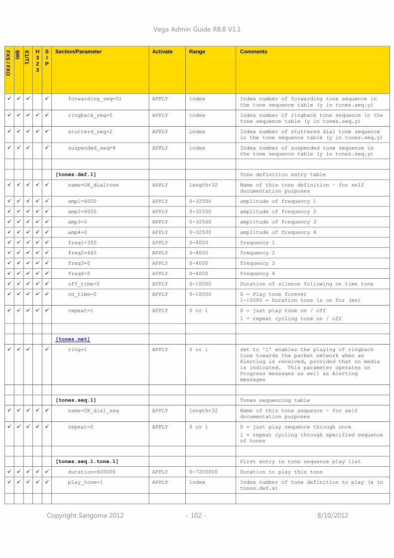
Vega Admin Guide R8.8 V1.1
Copyright Sangoma 2012 - 102 - 8/10/2012
FX
S / F
XO
BR
I
E1/T
1
H 3 2 3
S I P
Section/Parameter Activate Range Comments
forwarding_seq=51 APPLY index Index number of forwarding tone sequence in
the tone sequence table (y in tones.seq.y)
ringback_seq=5 APPLY index Index number of ringback tone sequence in the
tone sequence table (y in tones.seq.y)
stutterd_seq=2 APPLY index Index number of stuttered dial tone sequence
in the tone sequence table (y in tones.seq.y)
suspended_seq=8 APPLY index Index number of suspended tone sequence in
the tone sequence table (y in tones.seq.y)
[tones.def.1] Tone definition entry table
name=UK_dialtone APPLY length<32 Name of this tone definition – for self
documentation purposes
amp1=6000 APPLY 0-32500 amplitude of frequency 1
amp2=6000 APPLY 0-32500 amplitude of frequency 2
amp3=0 APPLY 0-32500 amplitude of frequency 3
amp4=0 APPLY 0-32500 amplitude of frequency 4
freq1=350 APPLY 0-4000 frequency 1
freq2=440 APPLY 0-4000 frequency 2
freq3=0 APPLY 0-4000 frequency 3
freq4=0 APPLY 0-4000 frequency 4
off_time=0 APPLY 0-10000 Duration of silence following on time tone
on_time=0 APPLY 0-10000 0 = Play tone forever
1-10000 = Duration tone is on for (ms)
repeat=1 APPLY 0 or 1 0 = just play tone on / off
1 = repeat cycling tone on / off
[tones.net]
ring=1 APPLY 0 or 1 set to '1' enables the playing of ringback
tone towards the packet network when an
Alerting is received, provided that no media
is indicated. This parameter operates on
Progress messages as well as Alerting
messages
[tones.seq.1] Tones sequencing table
name=UK_dial_seq APPLY length<32 Name of this tone sequence – for self
documentation purposes
repeat=0 APPLY 0 or 1 0 = just play sequence through once
1 = repeat cycling through specified sequence
of tones
[tones.seq.1.tone.1] First entry in tone sequence play list
duration=600000 APPLY 0-7200000 Duration to play this tone
play_tone=1 APPLY index Index number of tone definition to play (x in
tones.def.x)

Vega Admin Guide R8.8 V1.1
Copyright Sangoma 2012 - 103 - 8/10/2012
FX
S / F
XO
BR
I
E1/T
1
H 3 2 3
S I P
Section/Parameter Activate Range Comments
[users] User account section
radius_login=0 S/R 0,1 When enabled the Vega will send the login
credentials to the configured radius server.
If disabled the local copy of the login
credentials is used.
[users.admin] LOG Administrator user section
billing=0 LOG 0-2 0=No billing at login
1=Set „bill on‟ and „bill display on‟ at
login
2=Set „bill z‟ and „bill display on‟ at login
logging=3 LOG 0-6 0=no logging, 1=all messages logged, 2=Alert
and above messages logged, 3=Warning and
above messages logged, 4=Failure and above
messages logged, 5=Error and above messages
logged, 6=X_fatal messages logged … from next
login
prompt=%u%p> LOG length<32 Admin user prompt:
%n = host name
%i = host IP address (Lan 1)
%t = local time
%p = configuration path
%u = user name
remote_access=1 LOG 0 or 1 Disable / enable remote access (Telnet and
www)
timeout=1800 LOG 0 to 7200 1 to 7200 = timeout in seconds
0 = no timeout – but this can cause adverse
effects with the web browser
[users.billing] Billing user section (no www access)
billing=1 LOG 0-2 0=No billing at login
1=Set „bill on‟ and „bill display on‟ at
login
2=Set „bill z‟ and „bill display on‟ at login
logging=0 LOG 0-6 0=no logging, 1=all messages logged, 2=Alert
and above messages logged, 3=Warning and
above messages logged, 4=Failure and above
messages logged, 5=Error and above messages
logged, 6=X_fatal messages logged … from next
login
prompt=%u%p> LOG length<32 Billing user prompt:
%n = host name
%i = host IP address (Lan 1)
%t = local time
%p = configuration path
%u = user name
remote_access=1 LOG 0 or 1 Disable / enable remote access (Telnet)
timeout=0 LOG 0-7200 1 to 7200 = timeout in seconds
0 = no timeout
[users.user] Ordinary user section (no www access)
billing=0 LOG 0-2 0=No billing at login
1=Set „bill on‟ and „bill display on‟ at
login
2=Set „bill z‟ and „bill display on‟ at login

Vega Admin Guide R8.8 V1.1
Copyright Sangoma 2012 - 104 - 8/10/2012
FX
S / F
XO
BR
I
E1/T
1
H 3 2 3
S I P
Section/Parameter Activate Range Comments
logging=3 LOG 0-6 0= no logging, 1=all messages logged, 2=Alert
and above messages logged, 3=Warning and
above messages logged, 4=Failure and above
messages logged, 5=Error and above messages
logged, 6=X_fatal messages logged … from next
login
prompt=%u%p> LOG length<32 User user prompt:
%n = host name
%i = host IP address(Lan 1)
%t = local time
%p = configuration path
%u = user name
remote_access=1 LOG 0 or 1 Disable / enable remote access (Telnet)
timeout=0 LOG 0-7200 1 to 7200 = timeout in seconds
0 = no timeout
[users.1] User defined users
password=user1 LOG String 1 to
16 characters
Password for this user
privileges=none LOG admin or
privacy or
provision or
none
none: Default – User has no permissions
admin: Full access
privacy: User has reduced access as per list
above
provision: User has reduced access as per
list above
timeout=1800 LOG 0-7200 1 to 7200 = timeout in seconds
0 = no timeout
username=user1 LOG String 1 to
16 characters
Username for this user
[voice_prompt] User account section
F
X
S
mode=read_only read_only or
off
Enable (read_only) or disable readback of IP
parameters on an FXS Vega when the handset is
lifted and #1#1 is dialled

Vega Admin Guide R8.8 V1.1
Copyright Sangoma 2012 - 105 - 8/10/2012
7.8 Advanced configuration entries
The following configuration entries are to be used for advanced setup of the product. The
section [_advanced] is not listed by using wildcard section names from the SHOW command; it
must be explicitly specified by typing SHOW _advanced, or by specifying the whole
subsection/parameter path required.
FX
S / F
XO
BR
I
E1/T
1
H323
SIP
Section/Parameter Activate Range Comments
[_advanced] Advanced section
auto_apply=0 0 or 1 1 = Automatically action an APPLY
following each SET command
blocking_cause=34 APPLY 1-127 Cause code returned to caller when
incoming calls are blocked.
boot_debug=3 0 to 3 Save diagnostic state for next reboot
0 = debug disabled,
1 = Radvision debug level 1 (info only)
enabled
2 = Radvision debug level 4 (detail)
enabled
3 = debug disabled, and ask for code
selection at start up
cust_banner=none S/R String 1 to
80
characters
Define a custom banner that will be show
upon login or on execution of the “show
banner” command
oem_banner=0 P,S/R 0 or 1 0 = standard banner
1 = more generic / non Vega banner on web
browser
temp_alert_action=none none /
block /
fxs_shutdow
n
If an over-temperature condition is
observed, should calls be blocked, the
systm allowed to continue normal
operation, or should all FXS ports be
shutdown.
web_prefix=file: For Engineering Use Only
[_advanced.autoexec]
autoupgrade=0 Engineering use only
enable=1 0 or 1 Disable / enable autoexec functionality
lastconfig=none alpha
numeric
string
Internal storage for autoexec function
(stores last loaded config reference);
there is typically no need to alter this
parameter
scriptfile1=%mscript.txt alpha
numeric
string <=31
characters
Primary filename to use for autoexec
script
%i = IP address
%m = MAC address
%n = Name of Vega (lan.name)
%p = product type
scriptfile2=defaultscript.t
xt
alpha
numeric
string <=
31
Secondary filename to use for autoexec
script

Vega Admin Guide R8.8 V1.1
Copyright Sangoma 2012 - 106 - 8/10/2012
FX
S / F
XO
BR
I
E1/T
1
H323
SIP
Section/Parameter Activate Range Comments
characters
[_advanced.billing]
options=default APPLY String 1 to
63
characters
[_advanced.debug] Advanced diagnostic information
content=0 S/R 0-255 For engineering use only, do not change
entity=0 S/R 0-255 For engineering use only, do not change
entity_watchdog=on S/R 1 to 64
characters
For engineering use only, do not change
entity2=0 S/R 0-255 For engineering use only, do not change
module=0 S/R 0-255 For engineering use only, do not change
module2=0 S/R 0-255 For engineering use only, do not change
watchdog=on S/R on or off For engineering use only, do not change
[_advanced.dsl.port.1.]
tunnel_protocol.1.cpn=off
[_advanced.dsp]
allocation_mode=
least_used (E1T1)
least_used_all
(analogue/BRI)
APPLY best_match,
least_used,
least_used_
all,
least_used_
50
best_match: Vega allocates a channel on a
DSP which already has channels allocated
as long as it has the correct DSP image
and there is space on the DSP for a new
channel of the type being opened. (This
ensures that on systems which have
multiple DSP images, each with only a
subset of the full complement of codecs,
there is minimal chance of trying to
allocate a channel for a specific codec
and finding that no DSP has a free
channel which can run that codec.
least_used: this allows for a more even
spread of the call loading on the DSPs
within the system; Vega allocates a
channel on a DSP which is least loaded.
However, in order to preserve the ability
to switch compressed CODEC types the last
1 (or, in the case of 5441 DSPs which
work as pairs, the last 2) DSP(s) will be reserved and no channel will be allocated
on this/these DSP(s) until all the other
DSPs are 100% loaded.
least_used_all: same as least_used except
no DSPs are reserved for switching to
another compressed CODEC.
least_used_50: same as least_used but the
reserved DSPs will only be used if all
the other DSPs in the system are 50% or
more loaded.
digit_detect_mode=0 APPLY 0 or 1 Enable or disable digit detection on
E1/T1 interfaces

Vega Admin Guide R8.8 V1.1
Copyright Sangoma 2012 - 107 - 8/10/2012
FX
S / F
XO
BR
I
E1/T
1
H323
SIP
Section/Parameter Activate Range Comments
disable=none string <=
63
characters
For engineering use only, do not change
poll_interrupt=1 APPLY 0 or 1 For engineering use only, do not change
poll_period=8 APPLY 3 to 400 For engineering use only, do not change
rtp_pkt_buffer=4 APPLY 0 to 10 Enable use of an extended RTP packet
buffer to buffer packets before they are
sent to the DSP: 0=off, 1 to 10 sets
maximum buffer size.
t38_diags=0 IMM 0 or 1 Enable detailed diagnostics for T.38 –
For engineering use only, do not change.
t38_packet_time IMM 10 or 20 or
30 or 40
Specify length for each T38 packet.
[_advanced.dsp.buffering.fa
x]
depth=100 APPLY 10 … 200 T.38 packet resynchronisation buffer
depth
enable=0 (E1T1)
=1(analogue, BRI)
APPLY 0 or 1 Disable / enable T.38 packet
resynchronisation
[_advanced.dsp.buffering.vo
ice]
depth=60 APPLY 10 … 120 voice packet resynchronisation buffer
depth
enable=0 (E1T1)
=1(analogue, BRI)
APPLY 0 or 1 Disable / enable voice packet
resynchronisation
[_advanced.incoming_cause_m
apping]
Translation for Q.850 cause codes (see
„IN 18 Q.850 Cleardown cause codes‟ for
cause code details)
[_advanced.incoming_cause_m
apping.1]
Override values for cleardown cause
codes.
name=default IMM Length<32 Name of this cause mapping list – for
self documentation purposes
C1=1 APPLY 1-127 Cx=y substitutes the cause code y when
the cause code x is supplied.
C2=2 APPLY 1-127 “
-
C127=127 APPLY 1-127 “
[_advanced.h323]
RAS_h225_version=0 S/R 0 to 3 Set the h.225 version that is output in
the Gatekeeper RAS messages. 0 means the
real (RAD stack) version number is
reported, other values force an
artificial value.
rtd_failure_cause=41 S/R 1 to 127 Round trip delay failure cause code

Vega Admin Guide R8.8 V1.1
Copyright Sangoma 2012 - 108 - 8/10/2012
FX
S / F
XO
BR
I
E1/T
1
H323
SIP
Section/Parameter Activate Range Comments
F
X
O
nocallerid=No_Caller_ID S/R alpha
numeric
string
If no caller ID is received (typically
from incoming POTS FXO) then use this
string as the caller ID name in an
ongoing H323 call.
F
X
O
notavail=Not_Available S/R alpha
numeric
string
if caller ID is not available then use
this string as the caller ID name in an
ongoing H323 call.
F
X
O
restricted=Caller_ID_Blocke
d
S/R alpha
numeric
string
if the caller ID is blocked then use this
string as the caller ID name in an
ongoing H323 call.
[_advanced.h450] H.450 parameters
max_calls=30 0 to 240 For Engineering use only, do not change
max_services=30 0 to 240 For Engineering use only, do not change
[_advanced.h450.h450_2] Parameters for H.450_2
timer_ct-t1=20 For Engineering use only, do not change
timer_ct-t2=22 For Engineering use only, do not change
timer_ct-t3=24 For Engineering use only, do not change
timer_ct-t4=26 For Engineering use only, do not change
[_advanced.h450.h450_3] Parameters for H.450_2
timer_t1=20 For Engineering use only, do not change
timer_t2=22 For Engineering use only, do not change
timer_t3=24 For Engineering use only, do not change
timer_t4=26 For Engineering use only, do not change
timer_t5=28 For Engineering use only, do not change
[_advanced.isdn] Note: some of these parameters are
appropriate to CAS signalling too.
alert_with_progress=1 APPLY 0, 1 or 2 0= ignore / 1= accept / 2= assume : in-
band media indicator in ISDN ALERTING
messages
Only supported on ISDN; CAS signalling
schemes do not support an inband media
indication
call_proceeding_with_progre
ss=1
APPLY 0 or 1 Enable passage of in-band (audio)
information on call proceeding.
Applies to both CAS and ISDN.
connect_datetime=off off, nt,
te, always
Include „date and time‟ IE in ISDN
connect message:
off: never
nt: on calls on NT ports
te: on calls on TE ports
always: on all calls
disc_with_progress=1 APPLY 0 or 1 Enable passage of in-band (audio)
information on call disconnect.

Vega Admin Guide R8.8 V1.1
Copyright Sangoma 2012 - 109 - 8/10/2012
FX
S / F
XO
BR
I
E1/T
1
H323
SIP
Section/Parameter Activate Range Comments
Applies to both CAS and ISDN.
force_disconnect_progress=0 S/R 0 to 30 Time to play tone (in seconds)
N.B. this only operates on a Vega NT
interface
Normally when a disconnect is sent to an
ISDN call leg (from the Router / dial
planner) if there is no tone indicated as
being present (disconnect without
progress) then a Disconnect is sent on
the ISDN connection and no tone is
played. If this parameter is set to a non
zero value, the Vega will send a
Disconnect with Progress message and play
a tone out for the configured duration.
If the caller does not clear down, the
Vega sends a Release 30 seconds after the
disconnect with progress (T306 timer).
Setting this parameter to anything other
than 0 or 30 will leave the caller
listening to silence after the played
tone if they do not clear down.
IEs_to_tunnel=08,1c,1e,20,2
4,28,29,2c,34,40,6d,71,78,7
c,7d,7e,96
Comma
separated
list of IEs
List of IEs to tunnel when Tunnelling of
specific information elements has been
enabled.
See table in section 0 “Tunnelling full
signalling messages and IEs in ISDN
(ETSI, ATT, DMS, DMS-M1, NI, VN 3/4) and
QSIG” for details of interactions of
various parameters with IEs_to_tunnel.
int_id_present=0 APPLY 0 or 1 Channel ID Information Element: “IntID
Present field” in outgoing messages is
defined:
0 = implicitly
1 = explicitly (see
_advanced.isdn.interface_id)
interface_id=0 APPLY 0 to 2 If _advanced.isdn.int_id_present = 1,
then:
interface_id the Channel ID Information
Element: “Interface ID” in outgoing ISDN
messages
link_error_count=0 0..16 0: function disabled
1..16: count of cumulative (not
necessarily consecutive) frame errors
before link is removed and restored to
try and correct the problem
link_error_drop_time=2000 1..60000 Number of milliseconds to drop the ISDN
link for under error conditions to allow
it to clear and re-start (triggered by
link_error_count frame errors being
reached)
nt_alt_chan_if_collision=1 0 or 1 If two calls each attempt to use the same
channel, or a new call is set up and
tries to use a channel which has not yet
cleared, either the NT end or the TE end
can change the proposed channel for use.
Typically this channel conflict
resolution is carried out by the NT
device, but this parameter allows the
Vega to be configured to action the
resolution as a TE.

Vega Admin Guide R8.8 V1.1
Copyright Sangoma 2012 - 110 - 8/10/2012
FX
S / F
XO
BR
I
E1/T
1
H323
SIP
Section/Parameter Activate Range Comments
0 = TE device to apply the resolution
1 = NT device to apply the resolution
progress_with_progress=1 APPLY 0, 1 or 2 0= ignore / 1= accept / 2= assume : in-
band media indicator in ISDN PROGRESS
messages
Only supported on ISDN; CAS signalling
schemes do not support an inband media
indication
qsig_mode=non_contiguous APPLY contiguous/
non_contigu
ous
For E1 systems it is necessary to select
the Uq numbering scheme – to be the same
as the QSIG device to which the Vega is
attached
contiguous = Uqs 1..30
non-contiguous = Uqs 1..15 and 17..31
send_display_as=display none /
display /
facility
none = no display information will be
sent out over ISDN
display = display information sent to
ISDN will be in a display IE
facility = display information sent to
ISDN will be in a facility IE
Note 1. This parameter affects all E1T1
AND BRI LINKSs on the gateway
Note 2. As per Q.931 DISPLAY is only
handled NT to TE (it is not handled
TE to NT)
send_progress_as_alerting=0 0 or 1 0 = progress message passed through
1 = On receiving a progress message from
an ISDN interface convert it to an
alerting message before forwarding to
the VoIP interface or another ISDN
interface.
tn_heap_debug APPLY 0 or 1 For engineering use only, do not change
user_dialtone=0 APPLY 0 or 1 If set to 1, TE E1T1S OR BRISs will
generate dial tone
Only supported on ISDN (CAS does not
support dial tone generation)
user_progress=0 APPLY 0 or 1 If set to 1, TE E1T1S OR BRISs will
generate progress tones for alerting and
disconnect
Applies to both CAS and ISDN.
verify_IEs=1 0: disables checking of IE types (and
contents of those IEs)
(See section 0 “Verifying ISDN IEs
(Information Elements)” for more details)
verify_IE_contents=1 0: disables checking of contents of IEs
(See section 0 “Verifying ISDN IEs
(Information Elements)” for more details)
[_advanced.isdn.mwi]
type=normal APPLY normal /
ericsson
Use standard QSIG messaging for MWI
(Message Waiting Indication) or use
Ericsson proprietary method
[_advanced.isdn.mwi.ericsso
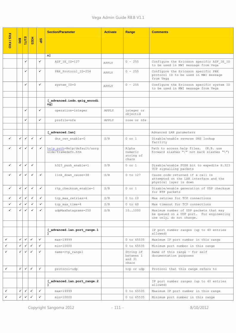
Vega Admin Guide R8.8 V1.1
Copyright Sangoma 2012 - 111 - 8/10/2012
FX
S / F
XO
BR
I
E1/T
1
H323
SIP
Section/Parameter Activate Range Comments
n]
ASF_IE_ID=127 APPLY 0 – 255 Configure the Ericsson specific ASF_IE_ID
to be used in MWI message from Vega
PBX_Protocol_ID=254 APPLY 0 - 255 Configure the Ericsson specific PBX
protocol ID to be used in MWI message
from Vega
system_ID=0 APPLY 0 – 255 Configure the Ericsson specific system ID
to be used in MWI message from Vega
[_advanced.isdn.qsig_encodi
ng]
operation=integer APPLY integer or
objectid
profile=nfe APPLY rose or nfe
[_advanced.lan] Advanced LAN parameters
dns_rev_enable=0 S/R 0 or 1 Disable/enable reverse DNS lookup
facility
help_path=Help/default/usrg
uide/framedefn.htm
Alpha
numeric
string of
chars
Path to access help files. (N.B. use
forward slashes “/” not back slashes “\”)
h323_push_enable=1 S/R 0 or 1 Disable/enable PUSH bit to expedite H.323
TCP signalling packets
link_down_cause=38 S/R 0 to 127 Cause code returned if a call is
attempted on the LAN interface and the
physical layer is down
rtp_checksum_enable=1 S/R 0 or 1 Disable/enable generation of UDP checksum
for RTP packets
tcp_max_retries=4 S/R 0 to 10 Max retries for TCP connections
tcp_max_time=4 S/R 0 to 60 Max timeout for TCP connections
udpMaxDatagrams=250 S/R 10..1000 Maximum number of UDP packets that may
be queued on a UDP port. For engineering
use only, do not change.
[_advanced.lan.port_range.1
]
IP port number ranges (up to 40 entries
allowed)
max=19999 0 to 65535 Maximum IP port number in this range
min=10000 0 to 65535 Minimum port number in this range
name=rtp_range1 String of
between 1
and 31
chars
Name of this range – for self
documentation purposes
protocol=udp tcp or udp Protocol that this range refers to
[_advanced.lan.port_range.2
]
IP port number ranges (up to 40 entries
allowed)
max=19999 0 to 65535 Maximum IP port number in this range
min=10000 0 to 65535 Minimum port number in this range

Vega Admin Guide R8.8 V1.1
Copyright Sangoma 2012 - 112 - 8/10/2012
FX
S / F
XO
BR
I
E1/T
1
H323
SIP
Section/Parameter Activate Range Comments
name=t38_tcp_range1 String of
between 1
and 31
chars
Name of this range – for self
documentation purposes
protocol=tcp tcp or udp Protocol that this range refers to
[_advanced.lan.port_range.3
]
IP port number ranges (up to 40 entries
allowed)
max=80 0 to 65535 Maximum IP port number in this range
min=80 0 to 65535 Minimum port number in this range
name=webserver String of
between 1
and 31
chars
Name of this range – for self
documentation purposes
protocol=tcp tcp or udp Protocol that this range refers to
[_advanced.lan.port_range.4
]
IP port number ranges (up to 40 entries
allowed)
max=19999 0 to 65535 Maximum IP port number in this range
min=10000 0 to 65535 Minimum port number in this range
name=t38_udp_range1 String of
between 1
and 31
chars
Name of this range – for self
documentation purposes
protocol=udp tcp or udp Protocol that this range refers to
[_advanced.lan.port_range.5
]
IP port number ranges (up to 40 entries
allowed)
max=5060 0 to 65535 Maximum IP port number in this range
min=5060 0 to 65535 Minimum port number in this range
name=sip_udp String of
between 1
and 31
chars
Name of this range – for self
documentation purposes
protocol=udp tcp or udp Protocol that this range refers to
[_advanced.lan.port_range.6
]
IP port number ranges (up to 40 entries
allowed)
max=5060 0 to 65535 Maximum IP port number in this range
min=5060 0 to 65535 Minimum port number in this range
name=sip_tcp String of
between 1
and 31
chars
Name of this range – for self
documentation purposes
protocol=tcp tcp or udp Protocol that this range refers to

Vega Admin Guide R8.8 V1.1
Copyright Sangoma 2012 - 113 - 8/10/2012
FX
S / F
XO
BR
I
E1/T
1
H323
SIP
Section/Parameter Activate Range Comments
[_advanced.lan.port_range.7
]
IP port number ranges (up to 40 entries
allowed)
max=5061 0 to 65535 Maximum IP port number in this range
min=5061 0 to 65535 Minimum port number in this range
name=sip_tls String of
between 1
and 31
chars
Name of this range – for self
documentation purposes
protocol=tcp tcp or udp Protocol that this range refers to
[_advanced.lan.port_range_l
ist.1]
Lists of IP port number ranges (up to 100
entries allowed)
list=1 1 to 40 Comma separated list of ranges (allows
non contiguous blocks of port numbers to
be defined
name=rtp_ports String of
between 1
and 31
chars
Name of this list of ranges – for self
documentation purposes
[_advanced.lan.port_range_l
ist.2]
Lists of IP port number ranges (up to 100
entries allowed)
list=2 1 to 40 Comma separated list of ranges (allows
non contiguous blocks of port numbers to
be defined
name=t38_tcp_ports String of
between 1
and 31
chars
Name of this list of ranges – for self
documentation purposes
[_advanced.lan.port_range_l
ist.3]
Lists of IP port number ranges (up to 100
entries allowed)
list=4 1 to 40 Comma separated list of ranges (allows
non contiguous blocks of port numbers to
be defined
name=t38_udp_ports String of
between 1
and 31
chars
Name of this list of ranges – for self
documentation purposes
[_advanced.logger]
log_in_secs=0 S/R 0 or 1 The time stamp in log messages is now
accurate to milliseconds (this is the
default behaviour). To revert back to the
previous format for seconds resolution
only set this value to 1.
options=default For Engineering use only
[_advanced.media]
V21_wait_time=4500 APPLY 1000 to Time (in milliseconds) to wait after a

Vega Admin Guide R8.8 V1.1
Copyright Sangoma 2012 - 114 - 8/10/2012
FX
S / F
XO
BR
I
E1/T
1
H323
SIP
Section/Parameter Activate Range Comments
10000 V.25 tone is detected for a V.21 signal.
After this time has expired without
detecting V.21 the Vega will change to
“data” mode
control_v25=fax IMM ignore or
fax or data
data: use G.711 data rather than T.38
codec for modem and fax calls
fax: use T.38 or G.711 for fax / modem
calls. T.38 for G3 fax (V.25 tone
followed by V.21 tone), and G.711 for
Super G3 fax (phase reversed V.25 tone)
and modem (V.25 tone but no V.21 tone)
ignore: ignore the V.25 tone
digit_threshold=-80 APPLY -80 to 0 Threshold above which a DTMF digit will
be detected
direct_RTP_enable=0 APPLY 0 or 1 0: A DSP resource will be allocated,
where possible to SIP to SIP calls.
1: For SIP to SIP calls (where licensed)
allow RTP to flow between call legs
without using DSP resource.
direct_TDM_enable=1 APPLY 0 or 1 0 = For loopback telephony to telephony
calls, loop the audio back on the packet
side of the DSP (i.e. after applying
codec and gain functionality of the dsp)
1 = For loopback telephony to telephony
calls pass the media directly from
port/channel to port/channel (i.e. loop
it as TDM data without passing it
to/through the DSPs).
dtmf_cadence_off_time=60 APPLY 25 to 10000 Off time for outgoing DTMF tones
dtmf_cadence_on_time=90 APPLY 25 to 10000 On time for outgoing DTMF tones
dtmf_level=-9 For engineering use only
dtmf_twist=0 For engineering use only
dynamic_codec_switch=off APPLY off, on When enabled the Vega will dynamically
change its transmitted codec to match
what is being received.
enforce_pkt_time_boundaries
=1
APPLY 0 or 1 0 = do not validate that the H.323 packet
time is within the range that can be
processed by the Vega – used where the
Vega is being connectd to by devices who
populate the packet time field wrongly
(field is in units of 10ms, not 1ms!)
1 = usual setting – do check that packet
time is valid
media_fail_detect_time=0 APPLY 25 to 10000 Off time for outgoing MF tones
mf_cadence_off_time=60 APPLY 25 to 10000 On time for outgoing DTMF tones
mf_cadence_on_time=90 APPLY For engineering use only
mf_level=-7 APPLY For engineering use only
mf_twist=0 APPLY
rtp_port_range_list=1 0 to 100 Index into
_advanced.lan.port_range_list.x that
defines the list of ranges of IP port
numbers to use for RTP
rx_udp_source_check=0 CALL 0 or 1 0 = Normal mode of operation – RTP

Vega Admin Guide R8.8 V1.1
Copyright Sangoma 2012 - 115 - 8/10/2012
FX
S / F
XO
BR
I
E1/T
1
H323
SIP
Section/Parameter Activate Range Comments
packets arriving on the agreed local IP
port will be played to the telephony
interface
1 = Before RTP packets arriving on the
agreed local IP port are played, they are
checked to see thet they have originated
from the expected remote endpoint IP
address and IP port number. Note: the
remote endpoint MUST send and receive RTP
data for that call on the same IP port.
sysload=85 For engineering use only, do not change
sysload_period=400 For engineering use only, do not change
[_advanced.mods]
bits=0x0000 CALL 1 to 33
characters
For engineering use only, do not change
[_advanced.outgoing_cause_m
apping.1]
Override values for cleardown cause
codes. For details on what the codes
mean, see Information Note „IN18 Q850
cleardown cause codes‟
name=default IMM Length<32 Name of this cause mapping list – for
self documentation purposes
C1=1 APPLY 1-127 Cx=y substitutes the cause code y when
the cause code x is supplied.
C2=2 APPLY 1-127 “
-
C127=127 APPLY 1-127 “
[_advanced.pacing.1]
delay=5 S/R 1..10000 For Engineering use only, do not change
threshold=120 S/R 1..1000 For Engineering use only, do not change
[_advanced.pots]
poll_timer=15 S/R 5 to 1000 Polling interval used within POTS
firmware (milliseconds) – For engineering
use only, do not change
save_pots_user_status=off APPLY on, off If enabled the Vega will try to save a
txt file containing the statuses of the
supplementary services (DND, call
forward, etc) for each port to the
default TFTP, FTP, HTTP or HTTPS server.
[_advanced.pots.fxo.1] FXO hardware interface configuration (up
to 10 entries)
F
X
O
call_connection_time=30 FXO disconnect supervision time that must
expire before cleardown tones will be
looked for

Vega Admin Guide R8.8 V1.1
Copyright Sangoma 2012 - 116 - 8/10/2012
FX
S / F
XO
BR
I
E1/T
1
H323
SIP
Section/Parameter Activate Range Comments
F
X
O
digital_rx_gain=0 APPLY -18 .. 6 Db level for input gain on FXO port
F
X
O
digital_tx_gain=0 APPLY -18 .. 6 Db level for output gain on FXO port
F
X
O
dtmf_holdoff_time=1500 APPLY 0 to 10000 Time in milliseconds to wait before
playing DTMF after offhook
F
X
O
early_line_seize=0 0 or 1 0 = a call coming in from the POTS side
will wait for the LAN side to connect
before the Vega FXO port seizes the POTS
line.
1 = the Vega FXO port will answer ("pick
up") any incoming POTS call immediately
ringing is detected.
F
X
O
early_line_seize_to=30 0 to 1000 If early_line_seize=1 and
early_line_seize_to is non-zero, a timer
will be started when ring tone has been
detected. The timer stops when the call
is connected on the LAN side. If, the
timer exceeds the configured timeout
value then the call is automatically
disconnected.
Note – for calls that are abandoned by
the calling party, where there is no
disconnect supervision, the line will
remain seized until the timeout is
reached, so closely following calls will
find the line busy).
If early_line_seize=1 and
early_line_seize_to=0, the timer does not
run and so a call into the FXO telephony
interface will not be dropped until the
LAN side connects then disconnects.
force_disconnects=1 APPLY 0 or 1 Force an off-hook then an on-hook if call
is dropped before POTS FXO answers
hookflash_time=200 APPLY 0 to 10000 Period for hookflash generation
(milliseconds)
impedance=ctr21 S/R ctr21,
default,
600R, 900R
Specifies the hardware impedance of the
FXO line interface
F
X
O
line_reversal_debounce_time
=50
APPLY 0 to 10000 Specify the time in milli seconds to
pause to debounce the line reversal
signal (allow the line reverse voltage to
maintain a steady state after a change)
line_reversal_detect=0 APPLY 0 or 1 Enable line reversal detection (aka
battery reversal)
loop_current_detect=0 APPLY 0 to 10000 0: disable loop current detection of
cleardown
>0: Enable loop current detection of
cleardown – parameter value = time in ms,
which if exceeded indicates a call clear.
port_not_released_cause=34 APPLY 1 to 127 Cause code returned if a new call is
presented to a POTS port before its
port_release_delay has expired. (Use
this in a group definition to re-present
the call to another port).
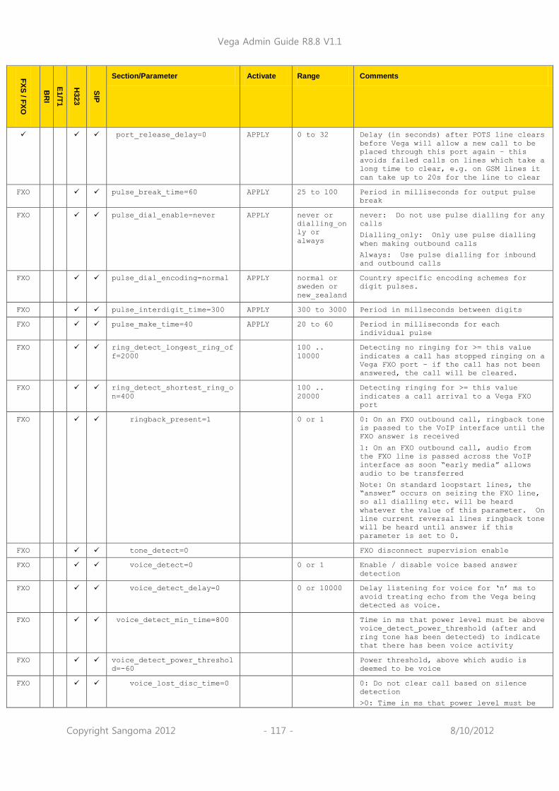
Vega Admin Guide R8.8 V1.1
Copyright Sangoma 2012 - 117 - 8/10/2012
FX
S / F
XO
BR
I
E1/T
1
H323
SIP
Section/Parameter Activate Range Comments
port_release_delay=0 APPLY 0 to 32 Delay (in seconds) after POTS line clears
before Vega will allow a new call to be
placed through this port again – this
avoids failed calls on lines which take a
long time to clear, e.g. on GSM lines it
can take up to 20s for the line to clear
FXO pulse_break_time=60 APPLY 25 to 100 Period in milliseconds for output pulse
break
FXO pulse_dial_enable=never APPLY never or
dialling_on
ly or
always
never: Do not use pulse dialling for any
calls
Dialling_only: Only use pulse dialling
when making outbound calls
Always: Use pulse dialling for inbound
and outbound calls
FXO pulse_dial_encoding=normal APPLY normal or
sweden or
new_zealand
Country specific encoding schemes for
digit pulses.
FXO pulse_interdigit_time=300 APPLY 300 to 3000 Period in millseconds between digits
FXO pulse_make_time=40 APPLY 20 to 60 Period in milliseconds for each
individual pulse
FXO ring_detect_longest_ring_of
f=2000
100 ..
10000
Detecting no ringing for >= this value
indicates a call has stopped ringing on a
Vega FXO port – if the call has not been
answered, the call will be cleared.
FXO ring_detect_shortest_ring_o
n=400
100 ..
20000
Detecting ringing for >= this value
indicates a call arrival to a Vega FXO
port
FXO ringback_present=1 0 or 1 0: On an FXO outbound call, ringback tone
is passed to the VoIP interface until the
FXO answer is received
1: On an FXO outbound call, audio from
the FXO line is passed across the VoIP
interface as soon “early media” allows
audio to be transferred
Note: On standard loopstart lines, the
“answer” occurs on seizing the FXO line,
so all dialling etc. will be heard
whatever the value of this parameter. On
line current reversal lines ringback tone
will be heard until answer if this
parameter is set to 0.
FXO tone_detect=0 FXO disconnect supervision enable
FXO voice_detect=0 0 or 1 Enable / disable voice based answer
detection
FXO voice_detect_delay=0 0 or 10000 Delay listening for voice for „n‟ ms to
avoid treating echo from the Vega being
detected as voice.
FXO voice_detect_min_time=800 Time in ms that power level must be above
voice_detect_power_threshold (after and
ring tone has been detected) to indicate
that there has been voice activity
FXO voice_detect_power_threshol
d=-60
Power threshold, above which audio is
deemed to be voice
FXO voice_lost_disc_time=0 0: Do not clear call based on silence
detection
>0: Time in ms that power level must be

Vega Admin Guide R8.8 V1.1
Copyright Sangoma 2012 - 118 - 8/10/2012
FX
S / F
XO
BR
I
E1/T
1
H323
SIP
Section/Parameter Activate Range Comments
below voice_detect_power_threshold for
call to be cleared
F
X
S
F
X
S
F
X
S
wink_on_disconnect=0 APPLY 0 to 5000
0: No wink on disconnect
1 to 5000: wink time and wink guard time
(e.g. if set to 500, Vega will wink for
500ms then return to line voltage for a
minimum of 500ms)
[_advanced.pots.fxs.1] FXS hardware interface configuration (up
to 10 entries)
F
X
S
call_fwd_no_answer_timeout=
15
APPLY 0-255 Time in seconds for which an FXS port
will apply ringing before call forward no
answer (CFNA) kicks in.
F
X
S
dialled_dtmf_detect=0 S/R For engineering use only. Not available
on certain hardware
0: use DSP to detect DTMF tones
1: use POTS chip to detect DTMF tones
F
X
S
digital_rx_gain=0 APPLY -18 .. 6 Db level for input gain on FXS port
F
X
S
digital_tx_gain=0 APPLY -18 .. 6 Db level for output gain on FXS port
F
X
S
dtmf_dialout_delay 0 .. 10000 Time to wait (in milli seconds) after
answer before dialing any FXS outdial
digits – specified in destination dial
plan TEL:
F
X
S
hookflash_debounce_time=75 APPLY 0 to 10000 Minimum time in milliseconds for
hookflash detection (line current loss
for less than this time will be ignored).
F
X
S
hookflash_time=500 APPLY 0 to 10000 Maximum time in milliseconds for
hookflash detection (line current loss
for greater than this time will cause a
call cleardown)
F
X
S
impedance=ctr21 S/R ctr21,
default,
600R, 900R
Specifies the hardware impedance of the
FXS interface
F
X
S
line_length=normal S/R normal,
long
FXS ports can drive a line length of up
to 8km (at 1 REN). Please contact the
relevant technical support representative
for using long drive lengths with REN
loading of more than 1 REN.
normal – Default – Line lengths up to 3km
long - Line lengths up to 8km
F
X
S
line_reversal=0 APPLY 0 or 1 Enable line reversal generation (aka
battery reversal)
F
X
S
loop_current_break=0 APPLY 0 or 1 Disable or enable Loop Current Disconnect
generation on FXS ports to indicate that
the other caller has cleared
F
X
S
loop_current_delay=9000 APPLY 0 to 100000 Time in milliseconds before Loop Current
is dropped after the far end has cleared.
(This gives the caller on the FXS port
time to clear their side of the call
before the Vega indicates call drop)

Vega Admin Guide R8.8 V1.1
Copyright Sangoma 2012 - 119 - 8/10/2012
FX
S / F
XO
BR
I
E1/T
1
H323
SIP
Section/Parameter Activate Range Comments
F
X
S
loop_current_time=300 APPLY 300 to
10000
Period that the Vega will drop the Loop
current for (in milliseconds) to indicate
other party has cleared … see also
loop_current_transition_time
F
X
S
loop_current_transition_tim
e=10
APPLY 0 to 100 When removing loop current, line
capacitance can delay the drop. Vega
actually drops theline curren for
loop_current_time
+loop_current_transition_time
F
X
S
max_pulse_break_time=70 APPLY 25 to 100 Maximum period for decoding pulse break
F
X
S
max_pulse_make_time=50 APPLY 20 to 60 Maximum period for decoding pulse make
F
X
S
min_pulse_break_time=40 APPLY 25 to 100 Minimum period for decoding pulse break
F
X
S
min_pulse_interdigit_time=3
00
APPLY
100 to 3000 Period to wait between digits
F
X
S
min_pulse_make_time=30 APPLY 20 to 60 Minimum period for decoding pulse make
F
X
S
onhook_line_reversal=0 APPLY 0 or 1 Enable onhook line reversal - a double
reversal of the line voltage to
acknowledging the loss of line current on
the telephone interface (i.e. to
acknowledge detection of the telephone
line clearing down)
F
X
S
onhook_line_reversal_interv
al=300
APPLY 30 to 10000 Duration between the first and second
revesal of the cleardown acknowledge
signal
F
X
S
pulse_dial_detection=1 APPLY
0 or 1 Enable or disable pulse dial detection
F
X
S
pulse_dial_encoding=normal APPLY normal or
sweden or
new_zealand
Country specific encoding schemes for
digit pulses.
F
X
S
visual_mwi=tone APPLY none, tone,
neon, both
None: no message waiting indication given
tone: Use FSK modem burst to indicate to
the phone that a message is waiting
neon: use FXS line voltage to indicate a
message waiting
(to light a neon lamp)
both: use FSK modem burst and FXS line
voltage to indicate a message waiting
F
X
S
vring_rms=80 APPLY 49.5, 60.5,
80
Ringing voltage to supply to FXS port in
ringing phase (49.5v rms = 70v pp, 60.5v
rms = 85.5v pp 80v rms = 113v pp) N.B.
Not all hardware platforms support 80v
setting.
F
X
S
wink_debounce_time=50 APPLY 0 .. 5000 At the end of a call do a wink after
wink_debounce_time after line current is
removed
F
X
wink_time=20 APPLY 0 .. 5000 At the end of a call do a wink for this
period after the wink_debounce_time

Vega Admin Guide R8.8 V1.1
Copyright Sangoma 2012 - 120 - 8/10/2012
FX
S / F
XO
BR
I
E1/T
1
H323
SIP
Section/Parameter Activate Range Comments
S
[_advanced.pots.ring.1] Ring description table for FXS POTS ports
(Power ringing)
frequency=25 S/R 16 or 20 or
25 or 30 or
40 or 50 or
60
Frequency to use for power ringing on FXS
ports
Note: 16 actually = 16.667Hz
name=External_UK S/R Length<32 Power ringing cadence name – for self
documentation purposes
repeat=1 S/R 0 or 1 0 = play sequence ring1 … ring3 through
once only
1 = repeat cycling through the ring
definitions ring1, 2, 3
ring1_on=400 S/R 0-10000 Ring 1 on time
ring1_off=200 S/R 0-10000 Ring 1 off time
ring2_on=400 S/R 0-10000 Ring 2 on time
ring2_off=2000 S/R 0-10000 Ring 2 off time
ring3_on=0 S/R 0-10000 Ring 3 on time
ring3_off=0 S/R 0-10000 Ring 3 off time
[_advanced.rad.debug] Debug
enable=0 For Engineering use only, do not change
filters=NULL S/R Length<32 For Engineering use only, do not change
startup=NULL For Engineering use only, do not change
[_advanced.rad.h225] Low level H.225 control
multicast_ip=224.000.001.04
1
IP address to send GRQ (multicast
gatekeeper request) to
multicast_port=1718 IP port number to send GRQ (multicast
gatekeeper request) to
rasPort=1719 IP port number on which Vega will listen
for RAS messages
retries=3 S/R 1 to 5 Number of retries for Gatekeeper
operations
timeout=4 S/R 0 to 20 Timeout period for Gatekeeper operations
ttl_advance=1 For Engineering use only, do not change
[_advanced.rad.h245] Low level H.245 control
capabilitiesTimeout=10 Timeout for H.245 set capabilities
message not responded to
channelsTimeout=10 Timeout for H.245 open logical channel
message not responded to
masterSlaveTimeout=10 Timeout for H.245 master / slave
determination message not responded to
requestCloseTimeout=10 Timeout for H.245 close logical channel

Vega Admin Guide R8.8 V1.1
Copyright Sangoma 2012 - 121 - 8/10/2012
FX
S / F
XO
BR
I
E1/T
1
H323
SIP
Section/Parameter Activate Range Comments
message not responded to
requestModeTimeout=10 Timeout for H.245 request mode message
not responded to
roundTripTimeout=5 S/R 0 to 999 Round trip delay – time to wait for the
RTD response after request has been sent
terminalType=0 Specifies the “terminalType” value
presented in the H.245 master/slave
exchange – the value 0 results in the
default value “60” (gateway) being used.
[_advanced.rad.q931] Low level Q.931 control in H.323 messages
callSignallingPort=1720 S/R 1 to 65535 IP port number that the Vega will listen
to for incoming H323 calls.
connectTimeout=120 S/R 1 to 9999 After an outgoing H323 call has been
started, this is the time (in seconds)
that the Vega will wait before
disconnecting the call if it does not
receive a connect message from the far
end.
maxCalls=60 How many calls can be handled in the RAD
stack
responseTimeout=5 S/R 1 to 9999 After an outgoing H323 call has been
started, this is the time (in seconds)
that the Vega will wait before it
disconnects the call if it does not
receive any response from the far end.
This is most commonly used to clear the
call when the far end or the system
gatekeeper have been disconnected from
the LAN.
[_advanced.rad.system] Low level h.323 system resource control
extraCalls=5 Rad stack resources - For engineering use
only, do not change
extraData=2048 Rad stack resources - For engineering use
only, do not change
extraNodes=50 Rad stack resources - For engineering use
only, do not change
maxBufferSize=20480 1024, 2048,
4096
Q.931 buffer resources - For engineering
use only, do not change
maxCalls=60 Rad stack resources - For engineering use
only, do not change
maxChannels=4 Rad stack resources - For engineering use
only, do not change
[_advanced.rfc2833] N.B. Out of Band DTMF must be configured
in the codec configuration for OTMF tones
to be sent as RFC2833 messages
digit_mute_time=0 Apply 0 to 2000 0: no mute
>0 (ms): on echoey analogue lines the
generation of DTMF tones by the vega can
cause enough echo that tones are sent
back to the originator. Adding a digit
mute means that the reverse path is muted

Vega Admin Guide R8.8 V1.1
Copyright Sangoma 2012 - 122 - 8/10/2012
FX
S / F
XO
BR
I
E1/T
1
H323
SIP
Section/Parameter Activate Range Comments
whilst the echo cancellor cuts in and
itself removes the tone.
emulation=off Apply off or
cisco
When set to cisco, emulate the way Cisco
populates RFC2833 DTMF indications.
marker_bit=0 S/R 0 or 1 This parameter is only applicable if
_advanced.rfc2833.ones_shot=1:
0 = ignore marker bit in received RFC2833
messages
1 = use marker bit in RFC2833 mesaages to
indicate start of new events
one_shot=1 IMM 0 or 1 This parameter controls how the Vega will
generate DTMF tones when it receives
RFC2833 DTMF messages.
0 = the true duration of the DTMF tones
(that the far end detector detected) will
be played
1 = single fixed length DTMF tone pulses
will be played however long the original
tones were (tone on period is defined by
dtmf_cadence_on_time)
tx_digit_off_duration=0 Apply 0 to 10000 Defines the on time duration for DTMF
indications sent using RFC2833. This
means that the TDM digit length will be
ignored.
tx_digit_on_duration=0 Apply 0 to 10000 Defines the on time duration for DTMF
indications sent using RFC2833. This
means that the TDM digit length will be
ignored.
tx_volume=10 S/R 0 to 63
Power level of tone reported in Tx
RFC2833 packets = -n dBm0 (e.g. 10 means
-10dBm0). RFC2833 says tones with a
power 0 to –36dBm0 must be accepted, and
below –55dBm0 must be rejected.
If tx_volume is set above 63 then a value
„36‟ is put in the RFC2833 messages
[_advanced.setup_mapping] Mapping of SETUP message elements (Vega
ISDN ports and All Vega H.323 setup
messages).
[_advanced.setup_mapping.1]
name=default IMM Length<32 Name of setup mapping list – for self
documentation purposes

Vega Admin Guide R8.8 V1.1
Copyright Sangoma 2012 - 123 - 8/10/2012
FX
S / F
XO
BR
I
E1/T
1
H323
SIP
Section/Parameter Activate Range Comments
[_advanced.setup_mapping.1.
bearer_capability]
l1_protocol=suplied supplied/
v110/
u_law/
a_law/
adpcm/
non_ccitt/
v120/ x31/
unused
Override Layer 1 protocol value in
outgoing setup message (to ISDN or H.323)
transfer_capability=speech supplied/
speech/
unresDigita
l/
resDigital/
3.1khz/
unresDigita
lTones
Override transfer capability value in
outgoing setup message (to ISDN or H.323)
transfer_mode=supplied supplied/
circuit/
packet
Override transfer mode value in outgoing
setup message (to ISDN or H.323)
transfer_rate=supplied supplied/
packet/
64kbit/
2x64kbit/
384kbit/
1536kbit/
multirate
Override transfer rate value in outgoing
setup message (to ISDN or H.323)
user_rate=supplied supplied/
56kbps/
64kbps/
unused
Override user rate value in outgoing
setup message (to ISDN or H.323)
[_advanced.setup_mapping.1
.called_party_number]
plan=supplied APPLY Unknown/
isdn_teleph
ony/ data/
telex/
national/
private/
supplied
Override the Numbering Plan
Identification field value for setup
messages (ISDN or H.323); supplied = do
not override the NPI value (pass it
through from the incoming call)
type=supplied APPLY Unknown/
internation
al/
national/
network_spe
cific/
subscriber/
abbreviated
/ supplied
Override the Type of Number field value
for setup messages (ISDN or H.323);
supplied = do not override the TON value
(pass it through from the incoming call
or planner.post_profile)

Vega Admin Guide R8.8 V1.1
Copyright Sangoma 2012 - 124 - 8/10/2012
FX
S / F
XO
BR
I
E1/T
1
H323
SIP
Section/Parameter Activate Range Comments
[_advanced.setup_mapping.1
.calling_party_number]
plan=supplied APPLY Unknown/
isdn_teleph
ony/ data/
telex/
national/
private/
supplied
Override the Numbering Plan
Identification field value for setup
messages (ISDN or H.323); supplied = do
not override the NPI value (pass it
through from the incoming call)
presentation=supplied APPLY Allowed/
restricted/
not_availab
le /
supplied
Override the Presentation Indicator field
value for setup messages (ISDN or H.323);
supplied = do not override the PI value
(pass it through from the incoming call)
screening=supplied APPLY not_screene
d/ passed/
failed/
supplied
Override the Screening Indicator field
value for setup messages (ISDN or H.323);
supplied = do not override the SI value
(pass it through from the incoming call)
type=supplied APPLY Unknown/
internation
al/
national/
network_spe
cific/
subscriber/
abbreviated
/ supplied
Override the Type Of Number field value
for setup messages (ISDN or H.323);
supplied = do not override the TON value
(pass it through from the incoming call)
[_advanced.setup_mapping.1.
nsf]
Network-Specific Facilities information
element (NSF IE) – sent in the ISDN SETUP
message (if this feature is enabled) for
NI1, NI2, DMS100 or 5ESS signalling
schemes. (Format of NSF IE is as per
Q.931 section 4.5.21)
T
1
coding=0 APPLY 0 to 31 Facility coding value
T
1
enable=0 APPLY 0 or 1 Enable the sending of the Network
Specific Facilities information element
T
1
id=NULL APPLY <=32
characters
ASCII ID of NSF IE. If set to “NULL” the
ASCII idenditfier, id_type and id_plan
will not be included in the NSF IE.
T
1
id_plan=0 APPLY 0 to 15 id_plan value, included in NSF IE if id
<> NULL
T
1
id_type=0 APPLY 0 to 7 id_type value, included in NSF IE if id
<> NULL
T
1
service=1 APPLY 0 or 1 Service flag
[_advanced.sip]
anonymous_display_name=Anon
ymous
S/R String <=
40
characters
Anonymous: when incoming ISDN call has
caller ID presentation indicator
marked as restricted, “display name”

Vega Admin Guide R8.8 V1.1
Copyright Sangoma 2012 - 125 - 8/10/2012
FX
S / F
XO
BR
I
E1/T
1
H323
SIP
Section/Parameter Activate Range Comments
in From field in outbound SIP message
= „Restricted user‟
<> Anonymous: when incoming ISDN call has
caller ID presentation indicator
marked as restricted, this value
specifies the name used as “display
name” in From field in outbound SIP
message
3xx_invite_to_proxy=0 S/R 0 or 1 0: send the redirected INVITE directly to
the destination specified in the
Contact: header in the 3xx message.
1: send the redirected INVITE to the
default proxy (and default proxy port)
no matter what is specified in the 3xx
Contact: field.
bye_also_invite_to_proxy=0 S/R 0 or 1 0: send the INVITE directly to the
destination specified in the "Also"
header in the BYE
1: send the new INVITE to the default
proxy no matter what is specified in
the "Also" header in the BYE.
cisco_cm_compatibility=0 S/R 0 or 1 If enabled the Vega will use a different
SIP signalling port for each of the
FXS interfaces.
disc_if_progress_with_cause
=0
0 or 1 O: function disabled
1: if a progress message with cause
indication is received on ISDN then
clear the call to SIP (e.g. if the
called number is Out of Order then
clear SIP call with SIP 500,
Destination out of order) – this
allows a SIP proxy to, for example,
sequentially try other phones if the
called party is unreachable at that
destination.
disc_with_progress=0 APPLY 0 .. 6000 O: Disconnect SIP call if disconnect ,
even if disconnect with progress
1 .. 6000: Enable passage of in-band
(audio) information on call disconnect –
pass media through for a maximum of this
number of seconds.
early_ok_timer=0 APPLY 0 .. 6000 O: function disabled
n: answer call with SIP OK after time n
seconds (from the 18x message) if the
call has not been answered on the
telephony interface before then.
N.B. not for general use – typically used
when connecting to ISDN endpoints
known not to provide a Connect.
escape_chars_in_uri=0 APPLY 0 or 1 If enabled the Vega will escape any non-
standard characters in SIP headers.
from_header_uri_params=NULL APPLY NULL /
string up
39 chars
Allows strings to be appended to From
header URI's, for example : ";user=phone"
and ";user=dialstring"
ignore_udp_bye=0 0 or 1 For engineering use only, do not change
ignore_udp_invite=0 0 or 1 For engineering use only, do not change
international_prefix=off APPLY off or
digits
Off = no prefix will be added
if prefix digits are defined then these
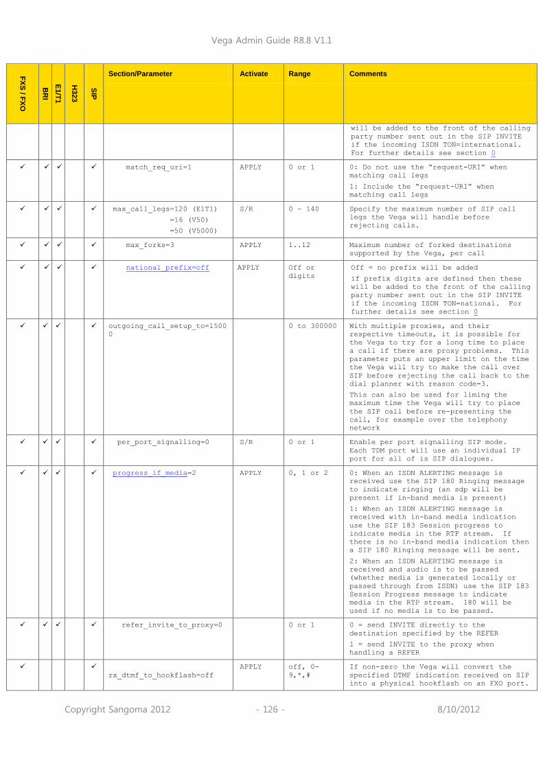
Vega Admin Guide R8.8 V1.1
Copyright Sangoma 2012 - 126 - 8/10/2012
FX
S / F
XO
BR
I
E1/T
1
H323
SIP
Section/Parameter Activate Range Comments
will be added to the front of the calling
party number sent out in the SIP INVITE
if the incoming ISDN TON=international.
For further details see section 0
match_req_uri=1 APPLY 0 or 1 0: Do not use the “request-URI” when
matching call legs
1: Include the “request-URI” when
matching call legs
max_call_legs=120 (E1T1)
=16 (V50)
=50 (V5000)
S/R 0 – 140 Specify the maximum number of SIP call
legs the Vega will handle before
rejecting calls.
max_forks=3 APPLY 1..12 Maximum number of forked destinations
supported by the Vega, per call
national_prefix=off APPLY Off or
digits
Off = no prefix will be added
if prefix digits are defined then these
will be added to the front of the calling
party number sent out in the SIP INVITE
if the incoming ISDN TON=national. For
further details see section 0
outgoing_call_setup_to=1500
0
0 to 300000 With multiple proxies, and their
respective timeouts, it is possible for
the Vega to try for a long time to place
a call if there are proxy problems. This
parameter puts an upper limit on the time
the Vega will try to make the call over
SIP before rejecting the call back to the
dial planner with reason code=3.
This can also be used for liming the
maximum time the Vega will try to place
the SIP call before re-presenting the
call, for example over the telephony
network
per_port_signalling=0 S/R 0 or 1 Enable per port signalling SIP mode.
Each TDM port will use an individual IP
port for all of is SIP dialogues.
progress_if_media=2 APPLY 0, 1 or 2 0: When an ISDN ALERTING message is
received use the SIP 180 Ringing message
to indicate ringing (an sdp will be
present if in-band media is present)
1: When an ISDN ALERTING message is
received with in-band media indication
use the SIP 183 Session progress to
indicate media in the RTP stream. If
there is no in-band media indication then
a SIP 180 Ringing message will be sent.
2: When an ISDN ALERTING message is
received and audio is to be passed
(whether media is generated locally or
passed through from ISDN) use the SIP 183
Session Progress message to indicate
media in the RTP stream. 180 will be
used if no media is to be passed.
refer_invite_to_proxy=0 0 or 1 0 = send INVITE directly to the
destination specified by the REFER
1 = send INVITE to the proxy when
handling a REFER
rx_dtmf_to_hookflash=off
APPLY off, 0-
9,*,#
If non-zero the Vega will convert the
specified DTMF indication received on SIP
into a physical hookflash on an FXO port.

Vega Admin Guide R8.8 V1.1
Copyright Sangoma 2012 - 127 - 8/10/2012
FX
S / F
XO
BR
I
E1/T
1
H323
SIP
Section/Parameter Activate Range Comments
rx_dtmf_to_disconnect=off
APPLY off, 0-
9,*,#
If non-zero the Vega will disconnect the
call on reception of the specified DTMF
digit
sip_headers_form=long APPLY short or
long
SIP headers can either be of the form To:
and From:, typically whole words (long
form) or t: and f:, typically single
letters (short form)
tel_srce=req_uri APPLY req_uri or
to_header
req_uri: TEL string presented to the dial
plan is taken from the characters
appearing between the "sip:" and the "@"
of the request-URI.
to_header: TEL string presented to the
dial plan is taken from the characters
appearing between the "sip:" and the "@"
of the To header.
to_header_uri_params=NULL APPLY NULL /
string up
39 chars
Allows strings to be appended to To
header URI's, for example : ";user=phone"
and ";user=dialstring"
use_maddr_in_contact=0 APPLY 0 or 1 0 = do not include maddr in the contact
header
1 = include maddr in the contact header
user_agent_header=1 APPLY 0 or 1 0 = no user agent header in SIP messages
1 = include user agent header in SIP
messages, e.g.:
User-Agent: Vega50-Wisc /
04.02.04xT025
user_agent_header_ext=NULL APPLY Up to 80
characters
NULL = no extension to be added to the
user-agent header
anything else = appended to user-agent
SIP header … characters must be “token”
characters as defined by RFC 3261
[_advanced.sip.access_netwo
rk_info]
enable=0 APPLY 0,1 Populate P-Access-Network-Info with TDM
bearer channel information.
[_advanced.sip.auto_connect
]
invite_delay_ms=0 APPLY 0 to 30000 Period in milliseconds that an outbound
SIP call will be delayed. After this
time has expired the SIP INVITE will be
sent as normal. The TDM side of the call
will be connected at the same time as the
timer starts.
mode=off APPLY off or
outgoing_si
p
off: Send SIP INVITE as normal and as
soon as possible.
outgoing_sip: Delay the transmission of
the outbound SIP call.
while_delay=do_nothing APPLY do_nothing
or
connect_to_
music_serve
r
do_nothing: Call originator will hear
nothing for the duration of the call
delay
connect_to_music_server: Call originator
will hear music on hold. MOH will need

Vega Admin Guide R8.8 V1.1
Copyright Sangoma 2012 - 128 - 8/10/2012
FX
S / F
XO
BR
I
E1/T
1
H323
SIP
Section/Parameter Activate Range Comments
to be configured separately.
[_advanced.sip.call_waiting
]
status_code=off APPLY off, up to
8
characters
If not off then Vega will return the
specified SIP message code to the waiting
party.
status_text=NULL APPLY NULL, up to
64
characters
If not NULL then Vega will use the
specified text in the textual part of the
SIP messge code in the ringing indication
to the waiting party.
[_advanced.sip.cause_to_res
ponse_mapping]
C1=404 APPLY 400 .. 699 SIP response yyy is sent if cleardown
cause code x is received.
C2=404 APPLY 400 .. 699 SIP response yyy is sent if cleardown
cause code x is received.
C3=404 APPLY 400 .. 699 SIP response yyy is sent if cleardown
cause code x is received.
C6=500 APPLY 400 .. 699 SIP response yyy is sent if cleardown
cause code x is received.
C7=500 APPLY 400 .. 699 SIP response yyy is sent if cleardown
cause code x is received.
C16=480 APPLY 400 .. 699 SIP response yyy is sent if cleardown
cause code x is received.
C17=486 APPLY 400 .. 699 SIP response yyy is sent if cleardown
cause code x is received.
C18=480 APPLY 400 .. 699 SIP response yyy is sent if cleardown
cause code x is received.
C19=480 APPLY 400 .. 699 SIP response yyy is sent if cleardown
cause code x is received.
C21=603 APPLY 400 .. 699 SIP response yyy is sent if cleardown
cause code x is received.
C22=410 APPLY 400 .. 699 SIP response yyy is sent if cleardown
cause code x is received.
C26=404 APPLY 400 .. 699 SIP response yyy is sent if cleardown
cause code x is received.
C27=500 APPLY 400 .. 699 SIP response yyy is sent if cleardown
cause code x is received.
C28=484 APPLY 400 .. 699 SIP response yyy is sent if cleardown
cause code x is received.
C29=501 APPLY 400 .. 699 SIP response yyy is sent if cleardown
cause code x is received.
C30=500 APPLY 400 .. 699 SIP response yyy is sent if cleardown
cause code x is received.
C31=404 APPLY 400 .. 699 SIP response yyy is sent if cleardown
cause code x is received.
C34=500 APPLY 400 .. 699 SIP response yyy is sent if cleardown
cause code x is received.

Vega Admin Guide R8.8 V1.1
Copyright Sangoma 2012 - 129 - 8/10/2012
FX
S / F
XO
BR
I
E1/T
1
H323
SIP
Section/Parameter Activate Range Comments
C38=500 APPLY 400 .. 699 SIP response yyy is sent if cleardown
cause code x is received.
C41=500 APPLY 400 .. 699 SIP response yyy is sent if cleardown
cause code x is received.
C42=503 APPLY 400 .. 699 SIP response yyy is sent if cleardown
cause code x is received.
C43=500 APPLY 400 .. 699 SIP response yyy is sent if cleardown
cause code x is received.
C44=500 APPLY 400 .. 699 SIP response yyy is sent if cleardown
cause code x is received.
C47=503 APPLY 400 .. 699 SIP response yyy is sent if cleardown
cause code x is received.
C49=500 APPLY 400 .. 699 SIP response yyy is sent if cleardown
cause code x is received.
C50=500 APPLY 400 .. 699 SIP response yyy is sent if cleardown
cause code x is received.
C57=403 APPLY 400 .. 699 SIP response yyy is sent if cleardown
cause code x is received.
C58=501 APPLY 400 .. 699 SIP response yyy is sent if cleardown
cause code x is received.
C63=500 APPLY 400 .. 699 SIP response yyy is sent if cleardown
cause code x is received.
C65=501 APPLY 400 .. 699 SIP response yyy is sent if cleardown
cause code x is received.
C66=500 APPLY 400 .. 699 SIP response yyy is sent if cleardown
cause code x is received.
C69=500 APPLY 400 .. 699 SIP response yyy is sent if cleardown
cause code x is received.
C70=500 APPLY 400 .. 699 SIP response yyy is sent if cleardown
cause code x is received.
C79=501 APPLY 400 .. 699 SIP response yyy is sent if cleardown
cause code x is received.
C81=500 APPLY 400 .. 699 SIP response yyy is sent if cleardown
cause code x is received.
C82=500 APPLY 400 .. 699 SIP response yyy is sent if cleardown
cause code x is received.
C83=500 APPLY 400 .. 699 SIP response yyy is sent if cleardown
cause code x is received.
C84=500 APPLY 400 .. 699 SIP response yyy is sent if cleardown
cause code x is received.
C85=500 APPLY 400 .. 699 SIP response yyy is sent if cleardown
cause code x is received.
C86=500 APPLY 400 .. 699 SIP response yyy is sent if cleardown
cause code x is received.
C88=488 APPLY 400 .. 699 SIP response yyy is sent if cleardown
cause code x is received.
C91=500 APPLY 400 .. 699 SIP response yyy is sent if cleardown
cause code x is received.
C95=400 APPLY 400 .. 699 SIP response yyy is sent if cleardown
cause code x is received.

Vega Admin Guide R8.8 V1.1
Copyright Sangoma 2012 - 130 - 8/10/2012
FX
S / F
XO
BR
I
E1/T
1
H323
SIP
Section/Parameter Activate Range Comments
C96=500 APPLY 400 .. 699 SIP response yyy is sent if cleardown
cause code x is received.
C97=500 APPLY 400 .. 699 SIP response yyy is sent if cleardown
cause code x is received.
C98=500 APPLY 400 .. 699 SIP response yyy is sent if cleardown
cause code x is received.
C99=500 APPLY 400 .. 699 SIP response yyy is sent if cleardown
cause code x is received.
C100=500 APPLY 400 .. 699 SIP response yyy is sent if cleardown
cause code x is received.
C101=500 APPLY 400 .. 699 SIP response yyy is sent if cleardown
cause code x is received.
C102=408 APPLY 400 .. 699 SIP response yyy is sent if cleardown
cause code x is received.
C111=400 APPLY 400 .. 699 SIP response yyy is sent if cleardown
cause code x is received.
C127=500 APPLY 400 .. 699 SIP response yyy is sent if cleardown
cause code x is received.
[_advanced.sip.info]
tx_dtmf=1 APPLY 0 or 1 1: Enable the transmission of DTMF
information in INFO messages (when Out
Of Band DTMF and DTMF using INFO
messages are enabled [dtmf_transport=
rfc2833_txinfo or info])
tx_hookflash=1 APPLY 0 or 1 1: Enable the transmission of Hookflash
information in INFO messages (when Out
Of Band DTMF and DTMF using INFO
messages are enabled [dtmf_transport=
rfc2833_txinfo or info])
[_advanced.sip.invite]
registered=0 APPLY 0 or 1 0: Send INVITE to the configured SIP
proxy
1: Only send INVITE to the proxy if the
SIP user associated with this call is
currently in a registered state – if not
registered, return a call cleardown cause
code 38.
This is used to allow faster re-
presentation of the calls if registration
is lost (e.g. proxy failure)
[_advanced.sip.kpml]
support_inter_digit_timer=0 APPLY 0 or 1 Use kpml to support Cisco interdigit
timeout
[_advanced.sip.loopback_det
ection]

Vega Admin Guide R8.8 V1.1
Copyright Sangoma 2012 - 131 - 8/10/2012
FX
S / F
XO
BR
I
E1/T
1
H323
SIP
Section/Parameter Activate Range Comments
enable=0 APPLY 0 or 1 Enable the detection of SIP loopbacks.
If a loopback is detected the veag will
attempt to untrombone by sending a REFER
message.
sip_header=NULL APPLY string 0-31
chars
SIP header to look for, to detect SIP
loopback
sip_header_regex=NULL APPLY string 0-
127 chars
Format of SIP header to look for, to
detect SIP loopback
[_advanced.sip.media]
T38_use_audio_port=0 APPLY 0 or 1 0: If set to 0 the Vega will use one IP
port number for audio codecs and a
different IP port number for T.38
1: If set to 1 the Vega uses the same
local IP port number for the duration
of the call, whatever re-invites may
change codecs, or destination of the
call. – Keeping a constant IP port
number can help with NAT traversal.
[_advanced.sip.nat]
mapping_timeout_s=0 APPLY 0 to 1200 Timeout for NAT mapping. 0 = off.
[_advanced.sip.oli] PSTN / POTS to SIP
ani_ii_digits=0 APPLY 0 .. 127 >0: Override / set up ANI Information
digit (II) (provides information similar
to CPC)
cisco=0 APPLY 0 or 1 1: Make CPC cisco format.
cpc_value=NULL APPLY Alpha
numeric
string
1..31 chars
<> NULL: Add calling party category field
„;cpc=<string>‟ to FROM: field, e.g.
„;cpc=payphone‟
[_advanced.sip.overlap]
allow_rx=0 APPLY 0 or 1 Allow the reception of Sip overlap
dialling. Each digit or group of digits
will arrive in separate SIP messages.
Depending on the configuration of the
outgoing call leg the digits may be
transmitted enbloc or overlap.
allow_tx=1 APPLY 0 or 1 All the transmission of SIP overlap
dialling. The generation of overlap
dialling depends on the behaviour of the
incoming call.
[_advanced.sip.privacy] See RFC 3326

Vega Admin Guide R8.8 V1.1
Copyright Sangoma 2012 - 132 - 8/10/2012
FX
S / F
XO
BR
I
E1/T
1
H323
SIP
Section/Parameter Activate Range Comments
standard=rfc3323 APPLY none,
rfc3323 or
rpid
none: no privacy information is passed
rfc3323: use the Privacy: header in SIP
messages as defined in RFC3323 and
RFC3325
rpid: enable reception of Caller id from
the SIP RPID header in received
INVITEs and the generation of the rpid
header in generated INVITEs
diversion_test=NULL APPLY String 0 to
255
characters
String to look for in SIP messages to
conclude that a call has been diverted.
[_advanced.sip.q931]
tx_tun_mode=off off,
cirpack,
req_uri
Mode to use to tunnel ISDN IEs over SIP
off: no tunnelling
cirpack: tunnelling using a Content_Type:
„application/vnd.cirpack.isdn-ext‟
req_uri: tunnelling using an X-UUI SIP
header
See table in section 0 “Tunnelling full
signalling messages and IEs in ISDN
(ETSI, ATT, DMS, DMS-M1, NI, VN 3/4) and
QSIG” for details of interactions of
various parameters with tunnel_IEs_only.
[_advanced.sip.reason] See RFC 3326
rx_enable=1 APPLY 0 or 1 0: Do not act upon the „Reason‟ header in
call clearing SIP messages
1: Use the Q.850 value received in the
„Reason‟ header and use it as the call
cleardown reason on the telecomms
interface
tx_enable=1 APPLY 0 or 1 0: Do not send the „Reason‟ header in SIP
call clearing messages
1: Use the Q.850 value received on the
telecomms interface and put it in the
reason header of the BYE / CANCEL or
INVITE response (e.g. 486 BUSY) message
[_advanced.sip.redirect]
preserve_to_header=1 APPLY 0 or 1 1 - When the Vega receives a 3xx INVITE
response, the SIP URI in the To header of
the next INVITE (triggered by the 3xx
response) is preserved
0 - When the Vega receives a 3xx INVITE
response, the SIP URI in the To header of
the next INVITE (triggered by the 3xx
response) is not preserved but is
overwritten with the URI in the request
URI
[_advanced.sip.refer]

Vega Admin Guide R8.8 V1.1
Copyright Sangoma 2012 - 133 - 8/10/2012
FX
S / F
XO
BR
I
E1/T
1
H323
SIP
Section/Parameter Activate Range Comments
norefersub=supported APPLY off or
supported
Add norefersub support to the Supported
header of SIP messages
refer_to_target=contact APPLY aor,
contact or
contact_no_
url_params
aor - Refer-To: to use the address of
record details, e.g.
Refer-To: sip:[email protected]
Contact - Refer-To: to use the
contact header details, e.g.
Refer-To:
[email protected]:5060;urlparam1=w
hatever
contact_no_url_params - Refer-To:
to use the contact header details,
but with url parameters stripped
e.g.
Refer-To:
[email protected]:5060
Assuming …
SIP/2.0 200 OK
To:
<sip:[email protected]>;tag=bf1666
63
From:
"port1"<sip:[email protected]>;tag=0
031-0006-87614925
Contact:
[email protected]:5060;urlparam1=w
hatever
replaces_disconnection=wait
_for_bye
APPLY wait_for_by
e or
early_bye
early_bye: When Vega is REFER target and
receives an INVITE with Replaces, the
Vega disconnects the replaced leg
immediately
wait_for_bye: When Vega is REFER target
and receives an INVITE with Replaces, the
Vega disconnects the replaced leg after 5
seconds, to allow the other endto send a
BYE message
[_advanced.sip.referred_by]
enable=1 APPLY 0 or 1 1 – Enable the referred-by header when
implementing a Refer
0 – Do not use referred-by header
[_advanced.sip.register]
contact_suffix=NULL APPLY String 1 to
127
characters
Suffix to add to the contact header of
all outbound REGISTER requests.
enable_transport_uri_param=
0
APPLY 0 or 1 Setting to 1 results in transport
parameter in Contact of REGISTER message
if the transport is TCP or TLS.

Vega Admin Guide R8.8 V1.1
Copyright Sangoma 2012 - 134 - 8/10/2012
FX
S / F
XO
BR
I
E1/T
1
H323
SIP
Section/Parameter Activate Range Comments
[_advanced.sip.response_map
ping]
R181=alerting alerting or
progress
On reception of a SIP 181 “Call is being
forwarded” message map to an ISDN
alerting or progress message
R182=alerting alerting or
progress
On reception of a SIP 182 “Queued”
message map to an ISDN alerting or
progress message
R183=alerting alerting or
progress
On reception of a SIP 183 “Session
progress” message map to an ISDN alerting
or progress message
[_advanced.sip.response_to_
cause_mapping]
Note: any cause code received in a SIP
„reason‟ header will be used in
preference to the mapping defined below.
R4xx=21 1 .. 127 Cleardown cause x is sent if SIP response
yyy is received.
R5xx=41 1 .. 127 Cleardown cause x is sent if SIP response
yyy is received.
R6xx=21 1 .. 127 Cleardown cause x is sent if SIP response
yyy is received.
R400=127 1 .. 127 Cleardown cause x is sent if SIP response
yyy is received.
R401=21 1 .. 127 Cleardown cause x is sent if SIP response
yyy is received.
R402=21 1 .. 127 Cleardown cause x is sent if SIP response
yyy is received.
R403=21 1 .. 127 Cleardown cause x is sent if SIP response
yyy is received.
R404=1 1 .. 127 Cleardown cause x is sent if SIP response
yyy is received.
R405=127 1 .. 127 Cleardown cause x is sent if SIP response
yyy is received.
R406=127 1 .. 127 Cleardown cause x is sent if SIP response
yyy is received.
R407=21 1 .. 127 Cleardown cause x is sent if SIP response
yyy is received.
R408=102 1 .. 127 Cleardown cause x is sent if SIP response
yyy is received.
R409=41 1 .. 127 Cleardown cause x is sent if SIP response
yyy is received.
R410=1 1 .. 127 Cleardown cause x is sent if SIP response
yyy is received.
R411=127 1 .. 127 Cleardown cause x is sent if SIP response
yyy is received.
R413=127 1 .. 127 Cleardown cause x is sent if SIP response
yyy is received.
R414=127 1 .. 127 Cleardown cause x is sent if SIP response
yyy is received.
R415=79 1 .. 127 Cleardown cause x is sent if SIP response
yyy is received.

Vega Admin Guide R8.8 V1.1
Copyright Sangoma 2012 - 135 - 8/10/2012
FX
S / F
XO
BR
I
E1/T
1
H323
SIP
Section/Parameter Activate Range Comments
R416=21 1 .. 127 Cleardown cause x is sent if SIP response
yyy is received.
R420=127 1 .. 127 Cleardown cause x is sent if SIP response
yyy is received.
R422=21 1 .. 127 Cleardown cause x is sent if SIP response
yyy is received.
R480=18 1 .. 127 Cleardown cause x is sent if SIP response
yyy is received.
R481=127 1 .. 127 Cleardown cause x is sent if SIP response
yyy is received.
R482=127 1 .. 127 Cleardown cause x is sent if SIP response
yyy is received.
R483=127 1 .. 127 Cleardown cause x is sent if SIP response
yyy is received.
R484=28 1 .. 127 Cleardown cause x is sent if SIP response
yyy is received.
R485=1 1 .. 127 Cleardown cause x is sent if SIP response
yyy is received.
R486=17 1 .. 127 Cleardown cause x is sent if SIP response
yyy is received.
R487=127 1 .. 127 Cleardown cause x is sent if SIP response
yyy is received.
R488=88 1 .. 127 Cleardown cause x is sent if SIP response
yyy is received.
R491=21 1 .. 127 Cleardown cause x is sent if SIP response
yyy is received.
R500=41 1 .. 127 Cleardown cause x is sent if SIP response
yyy is received.
R501=79 1 .. 127 Cleardown cause x is sent if SIP response
yyy is received.
R502=38 1 .. 127 Cleardown cause x is sent if SIP response
yyy is received.
R503=63 1 .. 127 Cleardown cause x is sent if SIP response
yyy is received.
R504=102 1 .. 127 Cleardown cause x is sent if SIP response
yyy is received.
R505=127 1 .. 127 Cleardown cause x is sent if SIP response
yyy is received.
R580=47 1 .. 127 Cleardown cause x is sent if SIP response
yyy is received.
R600=17 1 .. 127 Cleardown cause x is sent if SIP response
yyy is received.
R603=21 1 .. 127 Cleardown cause x is sent if SIP response
yyy is received.
R604=1 1 .. 127 Cleardown cause x is sent if SIP response
yyy is received.
R606=88 1 .. 127 Cleardown cause x is sent if SIP response
yyy is received.
[_advanced.sip.rport]

Vega Admin Guide R8.8 V1.1
Copyright Sangoma 2012 - 136 - 8/10/2012
FX
S / F
XO
BR
I
E1/T
1
H323
SIP
Section/Parameter Activate Range Comments
enable=1 APPLY 0 or 1 If enabled include the rport paramater in
SIP messages.
[_advanced.sip.sdp]
annexb_param=1 APPLY 0 or 1 If set to 1 then the G.729 annexb field
is included in the SDP of a sip
invite, e.g.
a=fmtp:18 annexb=no
or
a=fmtp:18 annexb=no
(G.729 annex b is VADU / silence
suppression for G.729)
clear_channel_mode=rfc4040 APPLY rfc4040 or
octet-
stream
When the „octet‟ or clear mode codec is
negotiated this parameter defines the
way the data stream should be encoded.
(RFC4040 is a standard and uses
RTP/AVP id 97, octet-stream is Vega
proprietary – available for backward
compatibility)
codec_selection=remote APPLY local or
remote
local: Vega will use its own codec
priority order when negotiating the
codec to use
remote: Vega will use the requested codec
priority order when negotiating the
codec to use
direction_attribute=on APPLY off or on off: a=<direction> is not generated by
the Vega and reception of it is
ignored
on: Enable handling of the a=<direction>
attribute
dsp_reserve_percent=25 APPLY 0 to 100 Percentage of the overall DSP pool that
should be reserved for non SIP to SIP
calls. i.e. TDM <-> SIP calls
ecan_enable=0 APPLY 0 or 1 If enabled the Vega will include echo
canceller information in the SDP section
of SIP messages similar to this:
a=ecan:fb off -
a=ecan:fb off -
fqdn=0 APPLY 0 or 1 0: use a dotted decimal IP address in the
"c=" (connection information) and "o="
(owner/creator and session identifier)
lines in the SDP.
1: use a FQDN (Fully Qualified Domain
Name) in the "c="(connection
information) and "o=" (owner/creator
and session identifier) lines in the
SDP (providing lan.name resolves to
lan.if.x.ipname)
maxptime_enable=0 APPLY 0 or 1 1: requests the a=maxptime attribute to
be included in the SIP sdp
nat_enable=1 APPLY 0 or 1 For engineering use only, do not change.
optimise_dsp_threshold APPLY 0 to 100 The threshold at which optimized codec
selection will start to be used for SIP
to SIP calls. This is calculated as a
percentage of the unreserved DSP pool.
(0=always optimised; 100=never optimised)
Optimising means that the Vega will try
to use the same codec wherever possible
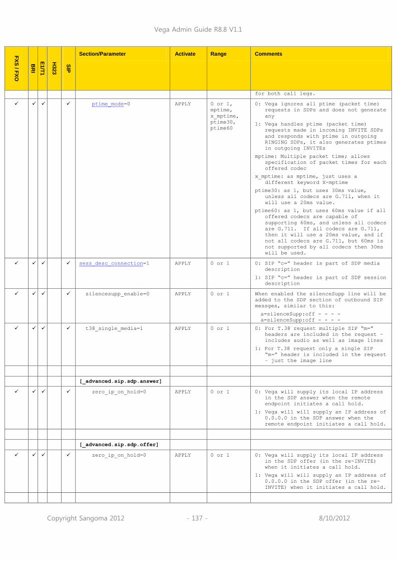
Vega Admin Guide R8.8 V1.1
Copyright Sangoma 2012 - 137 - 8/10/2012
FX
S / F
XO
BR
I
E1/T
1
H323
SIP
Section/Parameter Activate Range Comments
for both call legs.
ptime_mode=0 APPLY 0 or 1,
mptime,
x_mptime,
ptime30,
ptime60
0: Vega ignores all ptime (packet time)
requests in SDPs and does not generate
any
1: Vega handles ptime (packet time)
requests made in incoming INVITE SDPs
and responds with ptime in outgoing
RINGING SDPs, it also generates ptimes
in outgoing INVITEs
mptime: Multiple packet time; allows
specification of packet times for each
offered codec
x_mptime: as mptime, just uses a
different keyword X-mptime
ptime30: as 1, but uses 30ms value,
unless all codecs are G.711, when it
will use a 20ms value.
ptime60: as 1, but uses 60ms value if all
offered codecs are capable of
supporting 60ms, and unless all codecs
are G.711. If all codecs are G.711,
then it will use a 20ms value, and if
not all codecs are G.711, but 60ms is
not supported by all codecs then 30ms
will be used.
sess_desc_connection=1 APPLY 0 or 1 0: SIP “c=” header is part of SDP media
description
1: SIP “c=” header is part of SDP session
description
silencesupp_enable=0 APPLY 0 or 1 When enabled the silenceSupp line will be
added to the SDP section of outbound SIP
messges, similar to this:
a=silenceSupp:off - - - -
a=silenceSupp:off - - - -
t38_single_media=1 APPLY 0 or 1 0: For T.38 request multiple SIP “m=”
headers are included in the request –
includes audio as well as image lines
1: For T.38 request only a single SIP
“m=” header is included in the request
– just the image line
[_advanced.sip.sdp.answer]
zero_ip_on_hold=0 APPLY 0 or 1 0: Vega will supply its local IP address
in the SDP answer when the remote
endpoint initiates a call hold.
1: Vega will will supply an IP address of
0.0.0.0 in the SDP answer when the
remote endpoint initiates a call hold.
[_advanced.sip.sdp.offer]
zero_ip_on_hold=0 APPLY 0 or 1 0: Vega will supply its local IP address
in the SDP offer (in the re-INVITE)
when it initiates a call hold.
1: Vega will will supply an IP address of
0.0.0.0 in the SDP offer (in the re-
INVITE) when it initiates a call hold.

Vega Admin Guide R8.8 V1.1
Copyright Sangoma 2012 - 138 - 8/10/2012
FX
S / F
XO
BR
I
E1/T
1
H323
SIP
Section/Parameter Activate Range Comments
[_advanced.sip.sdp.t38param
s]
max_buffer=1 S/R 0 or 1 Include max buffer information in T.38
messages
max_datagram=1 S/R 0 or 1 Include max datagram information in T.38
messages
[_advanced.sip.simple_supps
erv]
enable=0 S/R 0 or 1 If enabled the Vega will generate a call
transfer request on reception of a DTMF #
[_advanced.sip.subscribe]
expires_max=360 IMM 0 to 65535 Expiry time to request in outbound SIP
SUBSCRIBE messages.
[_advanced.sip.tcp]
cleanup_old_sockets=0 S/R 0..120 0: release sockets as they are believed
to be finished with
1..120: only clear up sockets if the far
end close the socket, or all sockets
are used up. If all sockets are used
up, this value specifies how many
sockets to free up at a time. (For
engineering use only, do not change)
enable=1 S/R 0 or 1 0: Disable SIP TCP functionality (For
engineering use only, do not change)
1: TCP SIP functionality available
[_advanced.sipproxy] See also ‘IN_41-Vega Resilience Proxy’ on
www.wiki.sangoma.com/vega
crlf_keepalive=0 O..180 Time in seconds to send <CR> <LF> to keep
alive a TCP link
itsp_down_reg_expires=60 30..60000 Registration expires time to use if ITSP
is down – the shorter the time the sooner
calls will return to using the ITSP proxy
when the ITSP proxy recovers.
reg_forwarding_timeout=10 2..60
num_sockets=120 60..240 Number of sockets to allow
record_route=always always or
call_setup
server_header=1 0 or 1
[_advanced.tls.certificate]
key_usage_mandatory=0 APPLY 0 or 1 If set to 1 key must be present before
certificate will be accepted.
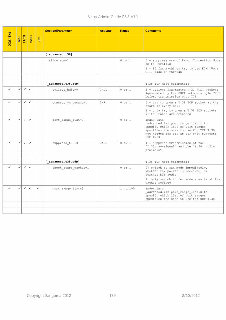
Vega Admin Guide R8.8 V1.1
Copyright Sangoma 2012 - 139 - 8/10/2012
FX
S / F
XO
BR
I
E1/T
1
H323
SIP
Section/Parameter Activate Range Comments
[_advanced.t38]
allow_ecm=1 0 or 1 0 = suppress use of Error Correction Mode
on fax traffic
1 = If fax machines try to use ECM, Vega
will pass it through
[_advanced.t38.tcp] T.38 TCP mode parameters
collect_hdlc=0 CALL 0 or 1 1 = Collect fragmented V.21 HDLC packets
(generated by the DSP) into a single TPKT
before transmission over TCP
connect_on_demand=1 S/R 0 or 1 0 = try to open a T.38 TCP socket at the
start of every call
1 = only try to open a T.38 TCP sockets
if fax tones are detected
port_range_list=2 0 or 1 Index into
_advanced.lan.port_range_list.x to
specify which list of port ranges
specifies the ones to use for TCP T.38 …
not needed for SIP as SIP only supports
UDP T.38
suppress_t30=0 CALL 0 or 1 1 = suppress transmission of the
“T.30: no-signal” and the “T.30: V.21-
preamble”
[_advanced.t38.udp] T.38 TCP mode parameters
check_start_packet=1 0 or 1 0: switch to fax mode immediately,
whether fax packet is received, or
further RTP audio
1: only switch to fax mode when first fax
packet rceived
port_range_list=3 1 .. 100 Index into
_advanced.lan.port_range_list.x to
specify which list of port ranges
specifies the ones to use for UDP T.38

Vega Admin Guide R8.8 V1.1
Copyright Sangoma 2012 - 140 - 8/10/2012
7.9 Exporting / Importing Configuration Data
Configuration can be exported and imported using the CLI and via a FTP or TFTP server or using the webserver and a PC.
Using Webserver
On the system page of the webUI is a section where configurations can be received and sent to the gateway:
Using the CLI
To export and import configuration data to/from an FTP or a TFTP server use the PUT and GET
commands. These can be run from the CLI prompt or the advanced>CLI Command section of
the web browser.
PUT file_path section writes the configuration parameters in section of the user
config memory to the FTP or TFTP server as named file file_path
GET file_path reads the file file_path from the FTP or TFTP server into user
config memory
1) Use GET with caution; GET overwrites parameters
2) This is very useful for archiving configuration parameters for re-load after an upgrade and to create template configuration files – allowing multiple Vegas to be configured with similar configurations
3) For more details on PUT and GET, see section Error! Reference source not found. ”Error! Reference source not found.”
The file generated by the PUT or TPUT operation is in the form of a script file, using the CP and SET
commands. When this script is echoed back to the CLI (using GET or by reading in via a terminal) it will recreate the appropriate configuration structures. Comment lines start with a „;‟ character and are ignored when the script is read back in.
The file can be edited on the server to change any entries specific to the individual gateway (eg.
lan.if.x.ip).
;
; Script generated using
; PUT MEM:0x95d398dc;length=0x00026666,buffer=0x95d398dc lan
; CONFIGVERSION:Vega:08/10/2010 12:41:34
;
set .lan.dns=0.0.0.0
set .lan.gateway=0.0.0.0
set .lan.ip=172.16.30.130
set .lan.name=Vega50WISC
set .lan.ntp=0.0.0.0
NOTE

Vega Admin Guide R8.8 V1.1
Copyright Sangoma 2012 - 141 - 8/10/2012
set .lan.ntp_local_offset=0000
set .lan.ntp_poll_interval=0
set .lan.subnet=255.255.248.0
set .lan.tftp=172.16.30.8
set .lan.use_dhcp=1
cp .
;
; PUT end
;

Vega Admin Guide R8.8 V1.1
Copyright Sangoma 2012 - 142 - 8/10/2012
8 USER ADMINISTRATION
8.1 Default Users
The User Administration facility allows username/password login to the Vega products. The web browser allows access by the admin user only, telnet and serial interfaces allow access by the three users, admin, billing, and user. Each username (admin, billing and user) grants a particular level of access to the system.
Admin
Full access privileges; can modify anything.
Default state for logging:- system: ALL levels, billing: OFF
Can modify any password
Can access UPGRADE menu
Can action privileged commands
Initial password = 'admin'
Any admin user logged in is informed of other administrator actions in the following situations:
When any user with „admin‟ privileges logs in.
When a user with „admin‟ privileges makes a change to a password.
Billing
Cannot modify database; can only view it
Default state for logging:- system: OFF, billing: ON
Cannot access UPGRADE menu
Cannot action privileged commands
Can execute commands bill display on/off/z
Initial password = 'billing'
User
Cannot modify database; can only view it
Default state for logging:- system: ALERT, billing: OFF
No access allowed for billing
Cannot access UPGRADE menu
Cannot action privileged commands
Initial password = „user‟
Passwords can only be changed by an admin user using the PASSWORD command. Stored passwords are encrypted and immune from the FACTORY RESET operation.
WARNING!
If the admin password is lost or forgotten the only way to restore the system is to perform a BOOT menu erase operation to erase all the system configuration. This can only be performed via the serial interface and will destroy all saved data in the Vega (including, for example, lan.if.1.ip).
Vega Admin Guide R8.8 V1.1
Copyright Sangoma 2012 - 143 - 8/10/2012
User Configuration
Customisation of each user type can be accomplished using the following parameters:
[users.admin], [users.billing] or [users.user]
remote_access=0/1
timeout=0-1000
logging=0-5
billing=0-5
prompt=…
The remote access parameter controls whether telnet and WWW access is allowable for this
user.
Timeout is an inactivity timer used to automatically log a user out of the interface if no commands
are typed within the specified period. The inactivity timeout period is specified in seconds from 1 to 7200; a value of zero has a special meaning “disable user inactivity timeouts”.
WARNING!
If timeout is set to 0, although telnet sessions close down
when exited, web browser sessions ONLY close down if exited using the “Log Off” button – sessions will be left hanging if the window close button is used, and they can only be cleared by rebooting the Vega, or explicitly using the Kill command.
The logging and billing parameters control the default state of “log” and “bill” at login:
For logging,
0=no logging,
1=all messages logged,
2=Alert and above messages logged,
3=Warning and above messages logged,
4=Failure and above messages logged,
5=Error and above messages logged,
6=X_fatal messages logged.
For billing,
0=bill display off,
1=bill display on at logon time
Prompt defines the format of the CLI prompt. The definition can consist of characters and any of
the following tokens:
%n = host name
%i = host ip address (Lan 1)
%t = local time
%p = configuration path
%u = user name
1. These [users] parameters are not used by the
Vega until the next login.
2. Telnet access for the BILLING user is prevented until the billing user password has been changed from its default value.
NOTE

Vega Admin Guide R8.8 V1.1
Copyright Sangoma 2012 - 144 - 8/10/2012
8.2 Configurable Users
The username and permissions levels of gateway users can now be configured. New users can be created with definable usernames, and one of four permissions levels can be configured:
“admin” o Full permissions for access to all parameters and commands
“privacy”. No access to the following: o show trace o sip monitor on o any bill command - "bill display on", "show bill", etc o any log command - "log display on", "show log", etc o any debug command - "debug enable", "debug on", etc o setting of certain configuration variables (see "privileged config variables" section above) o show support output is restricted to permitted commands o can only change password for themselves (not for any user) o "qos report on", "show qos cdr" and "show qos cdr last" will not show any Route
information.
none o User can login, but is not able to issue any commands (used when user has not been
fully configured)
provision o SIP passwords are hidden in put / sput output
This change applies to web browser, telnet, ssh and console access. To set the password of a new user the “password” command can be used.
Adding New Users
To create a new user:
admin >new users
admin users.5 >cd .
admin >
To assign a username for new user: -
admin >set users.5.username=Vega5
[users.5].username=Vega5
Configuration Parameter:
users.x.username
Possible values:
String between 1 and 63 characters in length
Parameter:
users.x.privileges
Possible values: none – Default – User has no permissions admin – Full access
privacy – User has reduced access as per list above
provision - User has reduced access as per list above

Vega Admin Guide R8.8 V1.1
Copyright Sangoma 2012 - 145 - 8/10/2012
Parameter: users.x.timeout
Possible values: 1800 – Time in seconds after which user will be logged out. Default 1800
8.3 Changing User Passwords
Users passwords can be changed by the administrator (admin) using the PASSWORD command:
admin >password
Enter user details
Username : admin
New password : ****
Confirm password : ****
Password change successful
LOG: 01/01/1999 00:00:31 TELNET (A)Rb9C01 password changed for user 'admin'
admin >
8.4 RADIUS Login Authentication
The Vega can optionally be configured to use a RADIUS server to authenticate users when logging in. On logging in the Vega sends the username and password to the configured radius server for verification rather than holding the password locally. The permissions for the user will be held locally on the Vega.
There is a 2 second timeout for the radius login. If the Vega doesn‟t receive a radius server response in 2 seconds, the login will fail.
A new CLI command has also been added that allows the configured radius server to be tested. Radius based login should be thoroughly tested before using. Failure to test may result in permanent lock out from the Vega.
If the user remote_access parameter is set to 0 and the user attempts to login via a console (serial) session RADIUS login authentication will not be used. The user password will be checked against the one configured in the Vega. If the user remote_access parameter is set to 1 then RADIUS authentication will be used for all logins, including serial access.
Configuration
Parameter added: users.radius_login
Possible values: 0 – Default – Do not use radius based authentication
1 – Use radius authentication
Parameter added:
logger.radius.server.1.auth_port
Possible values: 1 to 65535 – Port to use for radius authentication - Default 1813

Vega Admin Guide R8.8 V1.1
Copyright Sangoma 2012 - 146 - 8/10/2012
Test Command
A new command has been added to the Vega – radius login test – to check operation of the
configured radius server and users. This command causes a radius message to be sent to the configured radius server containing the credentials entered. Example
Assume a user has been setup with username of "admin" and correct password of "callme123". Issue the radius login test command with the correct credentials:
admin >radius login test admin callme123
RADIUS username and password ok.
Vega confirms configuration is correct.
Now issue the radius login test command with incorrect credentials (wrong password):
admin >radius login test admin callme124
RADIUS login test failed.
Vega indicates that login would have failed. The same message would be received if the radius server was incorrectly configured.
WARNING!
Do not enable radius login until the radius server has been configured and tested using the above command. If radius login is enabled but not correctly configured, the Vega will become inaccessible.

Vega Admin Guide R8.8 V1.1
Copyright Sangoma 2012 - 147 - 8/10/2012
8.5 Logged on users
Information concerning which users are logged in can be obtained from the “Connections active” section in the output from the “SHOW PORTS” command.
e.g. for a with 4 ISDN BRI interfaces:
admin >show ports
Physical ports:
Name Type Status
---------- ----- -------------------------
ISDN-1 WAN link-down (TE ) [X..]
ISDN-2 WAN link-down (NT ) [X..]
ISDN-3 WAN link-up (TE*) [X..]
ISDN-4 WAN link-up (NT ) [X..]
SIP -1 LAN 100Mbit Half Duplex
SIP -2 LAN link-down
DSL settings:
BRI 1: Top=BRI Net=ETSI Line=AZI Frm=S/T lyr1=g711Alaw64k
BRI 2: Top=BRI Net=ETSI Line=AZI Frm=S/T lyr1=g711Alaw64k
BRI 3: Top=BRI Net=ETSI Line=AZI Frm=S/T lyr1=g711Alaw64k
BRI 4: Top=BRI Net=ETSI Line=AZI Frm=S/T lyr1=g711Alaw64k
DSL statistics:
TX RX
Port Frames Bytes SLIPs Frames Bytes SLIPs CRC Error Bad
Frames
------ -------- ---------- ----- -------- ---------- ----- ---------- ------
----
BRI-1 0 0 -- 0 0 0 0 0
BRI-2 0 0 -- 12 36 0 0 0
BRI-3 271 1082 -- 271 1082 0 0 0
BRI-4 271 1082 -- 271 1082 0 0 0
Physical interfaces:
device RJ45 Connectors RJ21 Connector
------ ----------------- -----------------
ISDN port 1 (BRI) RJ45 port 1 N/A
ISDN port 2 (BRI) RJ45 port 2 N/A
ISDN port 3 (BRI) RJ45 port 3 N/A
ISDN port 4 (BRI) RJ45 port 4 N/A
System Fan: Normal
System Temperature: Normal
Connections active:
ID Port Address User Connection start time
--- ------ --------------- ---------------- ---------------------
1 RS-232 admin 01/01/1999 00:19:42
2 Telnet 192.168.1.108 admin 01/01/1999 00:22:04

Vega Admin Guide R8.8 V1.1
Copyright Sangoma 2012 - 148 - 8/10/2012
10* WWW 172.19.1.68 admin 18/01/2006 15:45:49
vega5002 has been running for 0 days, 00:50:41 hh:mm:ss
Statistics Cleared: Never
The “Connections active” section shows all the logged on users, including their login level (admin, billing or user) and for WWW and Telnet sessions the IP address of the terminal accessing the Vega. If there is a logged on session that should not be, the session can be killed by typing:
Kill <ID>
Where <ID> is the ID value from the ID column in the “Connections active” section.
Kill will not allow you to kill your own login session
(indicated in the connections section by a * against the ID)
NOTE

Vega Admin Guide R8.8 V1.1
Copyright Sangoma 2012 - 149 - 8/10/2012
9 THE DIAL PLANNER
The dial planner is the engine that processes incoming call requests. It provides three basic functions:
A. Routing
B. Number translation
C. Authentication
Routing: Based on the incoming information presented to the Vega (e.g. telephone number, Caller ID, incoming interface ID) the Vega can decide which interface and if appropriate what IP address to route the call to.
Number translation: The Vega can manipulate the telephone number received by adding prefixes / postfixes, inserting digits, modifying the order of received digits and using digits from other fields (like the Interface ID or the Caller ID) to create the new telephone number that is to be presented on the outbound leg of the call.
Authentication: When a call arrives the Vega looks for dial plans that match the received information. If no dial plan exists then the call will not be accepted. Only calls which have dial plans that match the incoming information will be onward routed.
Dial plans are a set of rules which say “if the information from the incoming call matches this dial plan‟s source tokens, then use this dial plan‟s destination tokens to onward route the call”
In the case of interworking with an H.323 gatekeeper or a SIP proxy, the dial planner will typically be configured with minimal information; the Routing, Number Translation and Authentication will be carried out by gatekeeper or the SIP proxy. In these cases:
For calls from telephony to LAN the dial planner can be used to augment the caller information with for example an indicator of which gateway the call arrived on, or perhaps re-format the caller information in a standard way for the gatekeeper / proxy if the incoming data is provided in different formats on different gateways.
For calls from LAN to telephony the call is presented to the dial planner after the gatekeeper / proxy has carried out its processing – in this way the Vega will typically just need to pass the call through, but may manipulate information to ensure that the call is presented to the correct telephony port and if required manipulate dial digit strings to format them for use on this specific telephony interface (if the gatekeeper has not already done this).
For a „presentation style‟ description on how to write dial plans please see Information Note „IN_20-Introduction to Vega Dial Plans‟.

Vega Admin Guide R8.8 V1.1
Copyright Sangoma 2012 - 150 - 8/10/2012
9.1 Interfaces
Each interface or interface group within the gateway that is capable of generating and / or receiving calls is assigned an interface ID value. The interface ID is a string of up to 32 characters defined in a parameter within the relevant interface‟s configuration section. By default the following interfaces are defined on the Vega product range:
Product Interface Default Interface IDs
System Configuration Entry Interface Type
Vega E1T1 E1 / T1 0401 .. 0404 e1t1/bri.port.n.group.m.interface Telecomm
Vega 50 Europa FXS / FXO / BRI FXS: 0101 .. 0108 FXO: 0201 .. 0208 BRI: 0301 .. 0308
pots.port.n.if.m.interface pots.port.n.if.m.interface e1t1/bri.port.n.group.m.interface
Telecomm
Vega 5000 FXS / FXO FXS: 0101 .. 0148 FXO: 0201 .. 0202
pots.port.n.if.m.interface pots.port.n.if.m.interface
Telecomm
All H.323 H.323 0501 h323.interface VoIP
All SIP SIP 9901, 9902, … 9905 sip.profile.x.interface=9901 VoIP
The dial planner uses interface IDs to specify the interface for both incoming and outgoing calls.
Although interface IDs can be changed, to make supporting the product easier it is recommended that these values are NOT changed.
E1/T1 = 0401 ... 0404 FXS = 0101 ... 0148
FXO = 0201 ... 0202
FXS = 0101 ... 0148
FXO = 0201 ... 0202
BRI = 0301 ... 0308
SIP = 9901 ... 9905
H.323 = 0501
SIP = 9901 ... 9905
H.323 = 0501
SIP = 9901 - 9905
H.323 = 0501
NOTE

Vega Admin Guide R8.8 V1.1
Copyright Sangoma 2012 - 151 - 8/10/2012
9.2 Dial Plan Tokens
Each incoming (source) and outgoing (destination) dial plan definition consists of a number of elements called tokens. Each token identifies a different attribute of the call address, and tokens are separated by a comma. The available tokens are:
IF:<up to 32 characters of: 0 to 9, a to z, #, *, underscore, dot >
e.g. IF:0101 Specify interface ID for incoming A-party or outgoing B-party (see below)
TEL:<0 to 9, a to z, #, *, underscore, dot>
e.g. TEL:123 Specify incoming or outgoing B-party (called party) telephone number in E.164 (numeric) or textual form
TELC:<e164-number> e.g. TELC:123 Specify the incoming or outgoing A-party (calling party) telephone number (Caller ID) in E.164 (numeric) format
TA:<ip address> e.g. TA:200.100.50.40 Specify outgoing B-party (called party) IP address or host name (Transport Address)
TAC:<ip address> e.g. TAC:200.100.50.40
Specify incoming A-party (calling party) IP address or host name (Transport Address of the Calling party)
DISP:<ascii-string> e.g. DISP:John Specify incoming or outgoing H.323, SIP or ISDN setup message display field
NAME:<ascii-string> e.g. NAME:vega400 Specify incoming or outgoing B-party (called party) H.323 ID
NAMEC:<ascii-string> e.g. NAMEC:vega400 Specify the outgoing A-party (calling party) H.323 ID
TYPE: TYPE:national Specify the outgoing Type Of Number field for the called party number
TYPEC: TYPEC:national Specify the outgoing Type of Number field for the calling party number
PLAN: PLAN:national Specify the outgoing Number Plan Information field for the called party number
PLANC: PLANC:national Specify the outgoing Mumber Plan Information field for the calling party number
SCRNC: SCRNC:not_screened Specify the outgoing Screening Indicator field for the calling party number
PRESC: PRESC:allowed Specify the outgoing Presentation Indicator field for the calling party number
There are two further tokens that can be used in destination dial plan entries:
CAPDESC:<capdesc-ID> e.g. CAPDESC:02 Specify which subset of codecs (CapDesc set) to offer for calls made to the LAN using this dial plan, i.e. only used where the dest dial plan entry has an IF:05, or IF:99

Vega Admin Guide R8.8 V1.1
Copyright Sangoma 2012 - 152 - 8/10/2012
QOS:<QOS profile>
e.g. QOS:03
Specify the Quality Of Service profile to use for calls made to the LAN using this dial plan.
Token names must be all capitals followed by a colon, e.g. TEL:
Examples:
Incoming address from a softphone: IF:0501,NAMEC:chris,TEL:12345
(These tokens specify a call arriving on the H.323 interface, interface 0501, from a caller
“chris”; who has dialled the number “12345”).
Outgoing address to a destination (SIP) gateway: IF:9901,TA:200.100.50.18,TEL:123
(These tokens specify a call being sent to IP address 200.100.50.18 via the SIP
interface, interface 99, presenting a telephone number “123”).
Outgoing call via a gatekeeper, or h323.if.x.default_ip: IF:0501,NAME:chris_456
(These tokens specify a call being sent to the H.323 interface, interface 0501 (no IP
address is needed here if the call is gatekeeper routed – the gatekeeper will supply the IP address – or if there is a default_ip configured) to an endpoint whose NAME is
“chris_456” ).
Incoming address from ISDN: IF:0401,TEL:5551000
(These tokens specify a call arriving on the first ISDN interface, interface 0401, where a
telephone number “5551000” was dialled).
The IF: (interface) token is mandatory for destination statements. Also, specifying a TA: token is required for destinations which are on the LAN, unless a gatekeeper or proxy is configured which will supply the IP address, or for H.323 systems where the parameter h323.if.x.default_ip
has been configured (default_ip) provides an implicit TA: for destination LAN dial plan entries if
no TA: is explicitly defined – however good practice recommends that TA:s are defined explicitly in the dial plans as it makes it easier for others to see exactly how the dial plan is designed to route the call).
All other tokens are optional and can be specified in any order.
NOTE

Vega Admin Guide R8.8 V1.1
Copyright Sangoma 2012 - 153 - 8/10/2012
The table and diagrams below define where the various tokens can be used.
H.323 LAN (0501) SIP LAN (9901) Telephony
Source Destination Source Destination Source Destination
IF: Mandatory Mandatory Mandatory
TEL:
TELC: Passed through
Passed through
Passed through
TA:
TAC:
DISP: ISDN only
NAME:
NAMEC:
TYPE:
TYPEC:
PLAN:
PLANC:
SCRNC:
PRESC
CAPDESC:
QOS:
SIP Main Tokens
LAN
Telephony
Telephony Source
IF: TEL: TELC:
LAN Dest
IF: TEL: TA: DISP: TELC: passed through
CAPDESC:
LAN Source
IF: TEL: TELC:
DISP: TAC:
Telephony Dest
IF: TEL: DISP: (ISDN
only)
TELC: passed through

Vega Admin Guide R8.8 V1.1
Copyright Sangoma 2012 - 154 - 8/10/2012
On a SIP Vega, if TA: is configured in the dial planner dest statement, and, if a call is placed and that SIP proxy / endpoint is down (does not respond with a TRYING, RINGING or OK in the appropriate timeframe), the Vega will try and use sip proxy 2, 3, … (if any are configured) to route the call. For details on configuring multiple proxies, see section 16.4.1.1 “Multiple SIP Proxy Support”
H.323 Main Tokens
LAN
Telephony
Telephony Source
IF: TEL: TELC:
LAN Dest
IF: TEL: TA: DISP: TELC: passed through
NAME: CAPDESC:
LAN Source
IF: TEL: TELC: DISP: TAC: NAME:
Telephony Dest
IF: TEL: DISP: (ISDN
only)
TELC: passed through
NOTE

Vega Admin Guide R8.8 V1.1
Copyright Sangoma 2012 - 155 - 8/10/2012
9.3 Dial Planner Structure
The dial planner structure comprises a series of numbered profiles, and within each is a set of individual plan entries. The structure within the system configuration databases is as follows:
[planner.profile.1]
name=<profile 1 name>
enable=1
[planner.profile.1.plan.1]
name=<profile 1‟s plan 1 name>
cost=x
srce=<source expression>
dest=<destination expression>
group=<group number>
[planner.profile.1.plan.2]
name=<description>
… etc.
[planner.profile.2]
name=<profile 2 name>
enable=1
[planner.profile.2.plan.1]
name=<profile 2‟s plan 1 name>
… etc.
… etc.
The idea is that each profile represents a set of plans relating to a particular area or sub-system. Each profile can be enabled or disabled individually; enabling a profile makes all plans within that profile active, disabling the profile makes all plans within that profile in-active. Any number of profiles (up to the maximum number of profiles) may be active at one time.
Profiles 20 to 25 are reserved for the use of Quick Config.
Show Plan
Dial plan details can be displayed either in raw stored form – from the user configuration memory – using SHOW PLANNER.PROFILE ; or alternatively they can be displayed from the runtime configuration
memory using SHOW PLAN . When using SHOW PLAN the dial plan information is syntax checked and processed to indicate exactly how the Vega will act upon the dial plan information. If there are any syntax errors that will prevent the Vega using dial plan entries these will be indicated.
Example SHOW PLAN – 3 plans in a single profile:
admin > show plan
Interfaces:
Interface Name Port Group Channels Type
---------- ---------- ----- ------ --------- -----
0101 POTS 1 1 2 POTS
0102 POTS 2 1 2 POTS
0103 POTS 3 1 2 POTS
0104 POTS 4 1 2 POTS
0105 POTS 5 1 2 POTS
0106 POTS 6 1 2 POTS
0107 POTS 7 1 2 POTS
0108 POTS 8 1 2 POTS
0501 H323 1 1 - LAN
H323 operating mode: NO GATEKEEPER, default gateway: 195.44.197.202
Profile 1: Vega50_default (enabled)
Index Grp Source Destination
/Cost Int'face Address Int'face Address
----- --- -------- ------------------------- -------- --------------------

Vega Admin Guide R8.8 V1.1
Copyright Sangoma 2012 - 156 - 8/10/2012
1/0 0 0101 TEL:<.*> 0501 TEL:<1>
2/0 0 0102 TEL:<.*59> 0501 TEL:<1>
3/0 0 0501 TEL:<.*> 0102 TEL:<1>
The above shows the nine interfaces on an H.323 Vega FXS, followed by a single profile of three plans.
To see the dial plan entries presented in priority order per port, see “Show Paths” in section 0 “Show Paths Command”
Adding Plan Entries
Each plan entry consists of four pieces of information: the source expression, the destination expression, the group, and the cost index. When a call arrives at one of the interfaces the dial planner searches all plans within profiles that are enabled in order of longest match (see below) for a matching source expression to the incoming called party number and interface (and other source tokens). Once one is found then it uses the corresponding destination expression to create an ongoing called party number and interface to be dialled.
To create a new dial plan entry, on the web interface select the dial plan “Add” button under the
specific profile from the dial plan page. On a CLI interface type new plan from the desired profile,
e.g.:
admin > profile 1
admin planner.profile.1> new plan
admin planner.profile.1.plan.4> show
[planner.profile.1.plan.4]
cost=0
dest=IF:<1>,TEL:<2>
group=0
name=new_plan
srce=TEL:<....><.*>
To configure the dial plan parameters overwrite the default values (provided by the Vega) with the new required values.
Moving to a specific Dial Plan entry
To get to a specific dial plan entry, on the web interface click the “Modify” button against the appropriate profile, then click the “Modify” button gainst the desired dial plan entry.
On a CLI interface use change path (CP) with the full path of the dial plan entry required. E.g.:
cp .planner.profile.2.plan.6
Alternatively, as a short cut use:
profile n
as a short form for writing
cp .planner.n
and use
plan m
as a short form for typing
cp plan.m
plan m works from any path that already has a planner.n set up, it will replace anything after
the planner.n with plan.m

Vega Admin Guide R8.8 V1.1
Copyright Sangoma 2012 - 157 - 8/10/2012
Creating a Source Expression
The source expression consists any combination of the above tokens. If the interface token is not supplied then the expression IF:.* for „any interface‟ is assumed. Regular expressions (wildcards) can be used to specify multiple patterns for the each source address (see below), e.g.
set srce=IF:0401,TEL:123 matches an incoming call on interface 01 (E1T1 1) calling the number 123
set srce=TEL:123.* matches an incoming call on any interface (LAN or telephony) calling a number starting with 123
TOKEN:value expressions are separated by a comma –
there must not be any space characters in the srce expression.
Creating a Destination Expression
The destination expression consists of the IF: token (mandatory) and any combination of TEL:, TELC:, DISP:, TA, CAPDESC: and for H.323 NAME: tokens, e.g.
set dest=IF:0501,TA:200.100.50.45,TEL:123,NAME:harry
Portions extracted from the matched source address can be substituted into the destination address to form a composite address; for this special tokens are used (see below).
TOKEN:value expressions are separated by a comma –
there must not be any space characters in the dest expression.
Regular Expressions
Regular Expressions (RE‟s) can be used in source expressions to specify patterns which match more than one possible number/address using special wildcard symbols. The wild card symbols available are as follows:
. any character
[abc] any character within the parentheses
[x-y] any character in the range x-y
[^abc] any character except those within the parentheses
* the character/expression before repeated zero or more times
+ the character/expression before repeated one or more times
? the character/expression before repeated zero or one times
\ literalise the following character (e.g. \* = * and not a repeat of the previous character)
< > capture the sequence in parentheses and store as <n> where n is the nth occurrence of <> in the source expression
These Regular Expressions / Wildcards must only be used in source expressions. Destination expressions must define the tokens absolutely.
For the destination expressions there are some Meta Characters available:
NOTE
NOTE
NOTE

Vega Admin Guide R8.8 V1.1
Copyright Sangoma 2012 - 158 - 8/10/2012
~ pause (a DTMF tone delay, e.g. used for waiting for a second dial tone on FXO outdial) – FXO only
<n> Insert the nth captured sequence from the source expression
Example of use of the <n> token:
srce=IF:9901,TEL:9<.*> dest=IF:0401,TEL:<1>
This dial plan looks for a call coming from the LAN (SIP profile 1) with a telephone number starting with a 9, but of non defined length. When this is detected a call will be made out of ISDN E1T11 (IF:0401) passing on the received telephone number excluding the leading 9. So, for an incoming SIP call where the called-party number = 9123456, the outbound call will dial 123456 on ISDN E1T1 1.
The above Regular Expressions / Wildcards can be used to create prefix and suffix patterns easily (and many more complex patterns), e.g.
srce=IF:0301,TEL:8<0[1-4]><.*> dest=IF:03<1>,TEL:<2>
This dial plan (for a Vega 50 BRI) will take an incoming ISDN BRI 1 call and if the called party number begins with „801‟, „802‟, „803‟, or „804‟ it will use the second two digits dialled to specify the ongoing interface (01 to 04), and the remaining digits will be passed on as the called party number, e.g. for an incoming call to ISDN BRI 1, where the called-party number = 803123, the outbound call will dial 123 on interface 0303 – ISDN BRI 3
Adding a Cost Index
The cost index is a number in the range 1 to 9 & 0. The cost index is used to set the priority on the corresponding dial plan entry for matching to incoming calls. If zero is configured then the dial planner will automatically select the most appropriate entry for an incoming call using the longest-match method. Any other value (1-9) sets a manual priority – 1 is the highest, 9 is lower; 0 (effectively 10) is the lowest.
Use “Show Paths” to see the resultant priority order of dial plan entries – see section 0
9.4 Fixed Length vs Variable Length
The dial planner is designed to forward calls immediately when a match is detected to a fixed length source expression. For example srce=TEL:123<…> represents a fixed length source
expression of 6 digits starting “123”. As soon as the last digit or character is received the Vega will begin forwarding the call to the corresponding outgoing interface.
In the case where a variable length source expression has been specified, for example
srce=TEL:123<.*> the Vega will need to use some other kind of indication to know when to
begin forwarding the call. Vegas support two mechanisms:
1) Source interface inter-digit timeout expiry.
2) Source interface block send character detected.
Both the timeout value and the block send character can be configured in the ISDN or POTS sections of the configuration database (depending upon the Vega being configured).
Only in the case of telephony interfaces are timeouts and block send characters used to forward calls. In the cases of H.323 and SIP, the dial planner automatically knows when to forward the call as dialled digits are sent “en-block”.
For incoming calls on POTS and ISDN interfaces always try to use fixed length source expressions because the call can be processed sooner, thus giving the caller a faster connection.
9.5 Longest match and cost matching
When an incoming call arrives at the gateway the dial planner scans the list of active profiles for a suitable match with a dial plan entry. If there is exactly one match suitable then this is chosen to

Vega Admin Guide R8.8 V1.1
Copyright Sangoma 2012 - 159 - 8/10/2012
progress the call. If more than one match is suitable then one of two algorithms is used to select the one to use cost matching or longest matching:
Cost Matching
If a manual cost in the range 1-9 has been entered for any matching dial plan entry then the lowest cost plan (ie highest priority) from this list is selected. In the case where more than one entry with the same cost exists, the first one encountered is used.
Longest Matching
If there are no manual costs in matching entries (i.e. all matching entries have a cost=0) then the dial planner uses the longest match algorithm to select a dial plan. This looks at the number of possible matches that can be derived from each source expression, and selects the one with the shortest list. For example:
TEL:12345 only one number can match, so the longest match cost is 1
TEL:1234[56] two numbers can match (12345,12346), so the longest match
cost is 2
TEL:1234. sixteen numbers can match, so longest match cost is 16
(12340,12341, … ,12349,1234*,1234#,1234A, … 1234D)
In the case where the longest match is the same for two or more addresses then the longest address is used.
Show Paths Command
The SHOW PATHS command is used to list dial plan entries in order of cost, (manual / longest match) either for all incoming interfaces, or for one particular specified interface.
The SHOW PATHS command, like SHOW PLAN, displays dial plan information from the runtime configuration memory; it is syntax checked and processed to indicate exactly how the Vega will act upon the dial plan information. If there are any syntax errors that will prevent the Vega using dial plan entries these will be indicated.
admin >show paths 0501
Sorted Dial Planner for interface: 0501
Source Destination Prof/
Int'face Address Int'face Address Plan
---------- --------------------------- -------- ------------------------- ----
IF:0501 H323 [1,1] summary:
0501 TAC:PHONE_<....>,TEL:<.*> <1> TEL:<2> 1/1 (*DISABLED*)
<....> TEL:.* 0501 TA:PHONE_<1>,TEL:<1> 1/2 (*DISABLED*)
.* TEL:<....><.*> <1> TEL:<2> 2/1
SHOW PATHS displays disabled profiles as well as enabled ones – the dial plan that the Vega will use is the first non-disabled entry that matches.
Try Command
The TRY command also displays the priorities for relevant dial plan entries whilst testing the dial planner using a sample incoming call address. For more details see section 9.13 Testing Plan Entries
NOTE

Vega Admin Guide R8.8 V1.1
Copyright Sangoma 2012 - 160 - 8/10/2012
9.6 Dial planner Groups
Dial planner groups can be used to group together dial plan entries to provide redundant routing. The group of dial plan entries can be configured to allow calls to be re-presented to other dial plans in that group until the call gets through, or until all dial plan entries in that group have been tried.
Groups may also be used to enable and disable specific or sets of dial plans under specific system conditions.
Groups And Redundancy (Call re-presentation)
See also section 9.7 “Call Presentation Groups”
When a group is created it contains a name and a list of cause codes. Any number of plans can then be assigned to this group (each plan can only be a member of a single group).
When a call arrives the Vega will use its cost and longest match algorithms to select the most appropriate dial plan to use. If the call fails and the dial plan is part of a group, then before rejecting the call the Vega will look at the group configuration to see if another dial plan may be suitable to route the call.
If the call has failed with a cause code which matches one of those listed in the group definition then the next appropriate dial plan in that group (according to cost – manual / longest match) will be tried – without the calling party knowing that a new call is being attempted. Ultimately there will be one of three possible outcomes:
1) The call succeeds using one of the dial plans.
2) All dial plan entries within the group have been tried and failed; the originating call is failed and the reason for failure given to the calling party is the cause code from the last call attempted.
3) A call fails for a reason other than those listed in the group definition; the originating call is failed and the reason for failure given to the calling party is this cause code.
This functionality can therefore be used to build redundancy into the Vega product by specifying more than one route out of the Vega for a particular incoming call. (Typically in scenarios like this all dial plans within the group will have identical srce expressions and will use cost to prioritise the order in which they are used)
E.g. first available phone on call busy:
admin planner.profile.1 >cp .planner.group.1
admin planner.group.1 >set name=UserBusy cause=17
[planner.group.1].name=UserBusy
[planner.group.1].cause=17
admin planner.group.1 >profile 2
list item added
admin planner.profile.2 >plan 1
admin planner.profile.2.plan.1 >set srce=IF:0501,TEL:<.*> dest=IF:0101,TEL:<1> group=1
[planner.profile.2.plan.1].srce=IF:0501,TEL:<.*>
[planner.profile.2.plan.1].dest=IF:0101,TEL:<1>
[planner.profile.2.plan.1].group=1
admin planner.profile.2 >plan 2
admin planner.profile.2.plan.2 >set srce=IF:0501,TEL:<.*> dest=IF:0102,TEL:<1> group=1
[planner.profile.2.plan.2].srce=IF:0501,TEL:<.*>
[planner.profile.2.plan.2].dest=IF:0102,TEL:<1>
[planner.profile.2.plan.2].group=1
admin planner.profile.2 >plan 3
admin planner.profile.2.plan.3 >set srce=IF:0501,TEL:<.*> dest=IF:0103,TEL:<1> group=1
[planner.profile.2.plan.3].srce=IF:0501,TEL:<.*>
Vega Admin Guide R8.8 V1.1
Copyright Sangoma 2012 - 161 - 8/10/2012
[planner.profile.2.plan.3].dest=IF:0103,TEL:<1>
[planner.profile.2.plan.3].group=1
admin planner.profile.2.plan.3 >apply
Applying planner configuration changes...
LOG: 03/04/2001 13:45:14 LOGGER (A)Rb2C00 config changes applied
admin planner.profile.2.plan.3 >
In this example any incoming call on interface 0501 (H.323) will be routed to the first found non-busy phone interface 0101, 0102, or 0103. The call will only be rejected if all interfaces 0101, 0102 and 0103 are unable to handle the call.
As well as using the CLI for configuration, groups may also be configured on the web browser interface – from the Dial Plan page.
Call representation can be used for calls being routed to the LAN interface as well as calls routed to the telephony interfaces, e.g. to present the call to different gateways to find a gateway to the PSTN that is not fully busy.
Cause Codes For Re-Presentation
[planner.group.1]
cause=3,34
Any Q.850 cause codes may be used to request re-presentation. Multiple cause codes may be specified as reasons for the call to be re-presented; do this by specifying them as a comma separated list of Q.850 cause codes (no spaces).
Frequently used values include:
3 – unreachable destination (e.g. on the LAN, the network may be down or the endpoint switched off, Sip proxy not accessible)
17 – endpoint busy
34 – PSTN network busy / no bandwidth on LAN
38 – Network out of order (on LAN also means Gatekeeper unreachable)
41 – Temporary failure (on LAN may be triggered by an “Adaptive Busy” message from the gatekeeper, indicating LAN congestion)
See “IN 18 Q850 cause codes” for a full list of cause codes and what they mean
In order to identify the cause code needed, it is often easiest to enable „log display on‟ on a command line interface and then make the failing call. Look at the disconnect reason code – this is the Q.850 cause code to use.

Vega Admin Guide R8.8 V1.1
Copyright Sangoma 2012 - 162 - 8/10/2012
1. On Vega FXS ports, cause code 18 – Ring Tone No
Reply – cannot be used to re-present calls to telephony interfaces onboard that unit – if re-presentation is required, the unit sourcing the outdial request will have to receive the cause code 18 over the LAN interface and using a special prefix send it back to the Vega FXS ports to try a different port. Alternatively use the dest_timeout functio in Call Presentation groups – see section 9.7 ”Call Presentation Groups”
2. To handle SIP proxy not available, also consider using backup proxies as cause code 3 takes about 20 seconds (if the SIP timers are at their default values: T1=500, T2=4000)
Groups enabling and disabling dial plans
The group definition can also be used to specify when dial plan entries are enabled / disabled. The conditions LAN active / inactive, Gatekeeper active / inactive, and time of day can be configured – if the configured condition is met then the dial plan entries that are in that group are enabled, otherwise they are disabled. The parameters are:
[planner.group.n]
lan=off/active/inactive
gatekeeper=off/active/inactive (H323 specific)
active_times=ssss-eeee
If the lan entry is configured active, then dial plans belonging to this group are only enabled for
routing calls when the LAN link is up. If lan=inactive is configured then dial plans belonging to
this group are only enabled for routing calls when the LAN link is down. The off condition
disables any checking of the lan condition (the status of the LAN will not disable the plans in this
group).
For H323 firmware, if the gatekeeper entry is configured active, then dial plans belonging to
this group are only enabled for routing calls when the gatekeeper is available and holds a valid gateway registration. If gatekeeper=inactive is configured then dial plans belonging to this
group are only enabled for routing calls when the Vega has no valid gatekeeper registration. The
off condition disables any checking of the gatekeeper registration condition (the status of
gatekeeper registration will not disable the plans in this group)
Active_times allows an inclusive activation time period to be entered (based on the system
clock displayed via SHOW TIME), where:
ssss = start time in 24hr format (e.g. 0700)
eeee = end time in 24hr format (e.g. 1700)
To activate dial plans outside of a particular time period then reverse the start/end times and adjust the times to avoid having both groups of dial plans active at the crossover minutes.
E.g.
0800-1800 enables dial plans in the period 8:00am to 6:00pm inclusive
1801-0759 enables dial plans for the remainder of the day, 6:01pm to 7:59am inclusive
The default is ssss=0000 and eeee=2359 – ie 24 hours permanently on.
NOTE
Vega Admin Guide R8.8 V1.1
Copyright Sangoma 2012 - 163 - 8/10/2012
When enabling multiple conditions, all conditions must be true for the dial plan to be enabled, e.g. If the lan entry is configured active and the gatekeeper entry is configured active, then both
the LAN link has to be up and the gatekeeper has to be available for the dial plan to be enabled for routing calls.
If selecting gatekeeper=inactive, dial plans in this group
must only route calls via telephony ports – if there is no gatekeeper to validate calls via the LAN, as defined in the H.323 specs the calls will fail.
WARNING!
The gatekeeper Active / Inactive feature may not be supported in this manner in future builds; it is better to use cause codes to represent calls where needed.
9.7 Call Presentation Groups
Call Presentation Groups provide an easy method for configuring a Vega to present calls to or through multiple physical interfaces. This is particularly useful on a trunking gateway to allow the Vega to find a non busy port / trunk to route the call through, and on a gateway connected to endpoints to find a non-busy endpoint or an end-point where the call is answered.
When configuring Call Presentation Groups the destination interfaces are defined in an ordered list, and the sequence mode tells the Vega how to use them. The cause parameter tells the Vega whether to try another interface or whether to terminate the call if it fails to a specific interface.
Call Presentation Groups define „Virtual Interfaces‟, and so they are used by specifying the required Call Presentation Group‟s interface ID as the destination IF: in a dial plan.
WARNING!
Call Presentation Group ‘virtual’ interface IDs must only be used in destination dial plan entries.
To accept calls form multiple interfaces in a source dial plan use wild cards, e.g. to accept calls from IF:0301 and IF:0303 use IF:030[13] in the source expression.
Configuring a Call Presentation Group
Specify the destination interfaces using dest, e.g.
dest = IF:0301|IF:0303
(BRI interfaces 0301 and 0303)
Specify the causes that should allow the call to try a different interface, e.g.
cause = 27, 34,41
(27 = desination out of order, 34 = channel in use, 41 = temporary failure … see also
section 0 ”Cause Codes For Re-Presentation”)
Specify the virtual interface number, e.g.
interface = 1003
(use a unique interface number)
NOTE
Vega Admin Guide R8.8 V1.1
Copyright Sangoma 2012 - 164 - 8/10/2012
Enable the Call Presentation Group, e.g.
enable = 1
Other parameters allow further control of the call presentation group:
Specify the way to use the list of interfaces, e.g.
seq_mode = linear_up
(linear_up, round_robin or random)
Specify the maximum number of different interfaces the Vega should try in this CPG, e.g.
max_dest_attempts = 2
(typically this is the number of interfaces in the „dest‟ list)
If the dest_timeout timeout occurs (endpoint just rings forever) define what to do, e.g.
dest_timeout_action = try_next_dest
(either try next CPG destination, or hangup … hangup means exit this CPG (call re-presentation can re-present call if required))
Specify the time to leave destination ringing, e.g.
dest_timeout = 180
(180 sec = 3 minutes)
Specify a name, e.g.
name = find_free_PSTN
(for self documentation choose a name that defines what this CPG does)
Interaction of Call Presentation Groups and Call re-presentation
Call Presentation Groups are called up by specifying them as the IF: in the dest part of a dial plan entry. If the Call Presentation Group exits (because it has exceeded the number of interfaces to try, has received a cleardown reason not listed in the cause list or has reached the dest_timeout and dest_timeout_action is hangup) then if the dial plan entry is in a call re-presentation group, the call re-presentation will be actioned.
9.8 Hot-Line Facility (Long-line extension)
Vega products support a “hot-line” facility which allows the dial tone played to the calling party to be sourced from the destination PBX / Network rather than from the local Vega itself. (This is especially useful where the PBX or Network uses special forms of dial tone, for example stuttered dial tone to indicate voice mail “message waiting”.)
When the handset of a phone attached to a Vega FXS port configured for “hot-line” is lifted, the FXS port will immediately route the call to a specified destination. This is typically used together with a Vega 50 BRI, Vega E1T1 or a Vega 50 FXO also configured in “hot-line” mode – the destination gateway seizes the line towards the PBX or Network and the dial tone so produced is routed back over the VoIP network to the calling party. Any digits now dialled will be passed to the PBX or Network that is playing the dial tone.
1. To allow the dial tone to be passed over the VoIP
network, early media must be configured in the VoIP gateways (e.g. use_faststart, accept_faststart=”after proceeding”, use_early_h245 and accept_early_h245)
2. DTMF must be configured as out-of-band if the destination unit is a Vega E1T1, or Vega 50 BRI so that the destination unit can use the digits as dialled digits rather than passing through the DTMF tones.
NOTE

Vega Admin Guide R8.8 V1.1
Copyright Sangoma 2012 - 165 - 8/10/2012
Vega FXS Port Hot-Line
The Vega FXS port is configured for “hot-line” operation by omitting the telephone number or telephone number token from the source dial plan expression.
e.g. srce=IF:0101,TEL:
or srce=IF:0101
1. SIP does not support null or zero length dialled
numbers, so when the hot-line call is forwarded over SIP, a dummy telephone number must be sent. E.g. srce=IF:0101,TEL: dest=IF:9901,TEL:\* sends a Star DTMF character if hotline is configured
Vega FXO Port Hot-Line
Vega FXO ports support “hot-line” mode to allow VoIP calls to be routed to the destination PBX or Network without a dialled number being passed.
To activate the hot-line facility simply omit the telephone number or telephone number token from the destination dial plan expression:
e.g. dest=IF:0201,TEL:
or dest=IF:0201,TEL:~
or dest=IF:0201
(or dest=IF:0201,TEL:<1> ; where <1> is empty)
When the call arrives, the Vega will just seize the line (without dialling any digits) and this will provoke a dial tone response. Subsequent DTMF digits received by the Vega FXO port will then be played to the PBX or Network, which it will interpret as dialled digits.
Vega 50 BRI and Vega E1T1 Hot-Line
Vega 50 BRI, and Vega E1T1 gateways support “hot-line” mode to allow VoIP calls to be routed to the destination network without a dialled number being passed.
Dial tone is readily available from BRI networks, but only sometimes available from PRI networks.
To activate the hot-line facility simply omit the telephone number or telephone number token from the destination dial plan expression:
e.g. dest=IF:0401,TEL:
or dest=IF:0401
(or dest=IF:0401,TEL:<1> ; where <1> is empty)
When the call is forwarded from the Vega to the ISDN PBX or Network it will send a SETUP message with no dialled digit information, and this will provoke a dialtone response. Subsequent out of band DTMF digits received by the Vega will then be sent to the ISDN PBX or Network as dialled digit information (provided that early media is established on the incoming H.323 or SIP side of the gateway).
NOTE
NOTE

Vega Admin Guide R8.8 V1.1
Copyright Sangoma 2012 - 166 - 8/10/2012
9.9 Overlap Dialling
The default behaviour of Vega gateways is to use enbloc dialling, where all digits are sent when the call is in the setup phase. This can cause unacceptable post dial delay (PDD) in some countries. To overcome this Vegas can be configured to use overlap dialling when originating calls.
Outgoing call setup using overlap dialling is now supported for the following call types:
TDM to SIP
SIP to TDM
TDM to TDM
The following TDM interfaces support overlap dialling:
ISDN (where allowed by the protocol)
FXO
FXS
Once enabled the behaviour of this feature is controlled via the dial plan:
Any call matching a dial plan containing “.*” in the source TEL token will be treated as an overlap call.
Any digits preceding the “.*” will be collected before the call is routed
This provides control for when the routing decision is taken
Configuration
Parameter: planner.allow_tx_overlap
Possible values: 0 – Default – Disable overlap dialling
1 – Enable overlap dialling transmission for all valid interfaces
Parameter: _advanced.sip.overlap.allow_tx
Possible values: 0 – Default – Disable outbound SIP overlap dialling
1 – Enable overlap dialling for outbound SIP calls
Parameter: _advanced.sip.overlap.allow_rx
Possible values: 0 – Default – Disable inbound SIP overlap dialling
1 – Enable overlap dialling for inbound SIP calls
Example Usage
User Dials Vega Dial Plan Vega Routes Call on Reception of
01344 784900 TEL:<.*> 0
00 1 877 834 4470 TEL:00<.*> 00
00 1 877 834 4470 TEL:<….*> 001

Vega Admin Guide R8.8 V1.1
Copyright Sangoma 2012 - 167 - 8/10/2012
Sample Call Flow for SIP Overlap Dialling
9.10

Vega Admin Guide R8.8 V1.1
Copyright Sangoma 2012 - 168 - 8/10/2012
9.11 LocalDNS Name Table or DNS-based Indirection
The LAN configuration section contains a local DNS table of host names and IP addresses. This provides local (internal) DNS lookup for name to IP and IP to name. Lookups in this local DNS table take priority over use of the external DNS server (whose IP address may also be set up). This allows names to be used in dial plans instead of dotted decimal IP addresses.
The advantage of using names is that IP address dependencies can be moved to a single table (the local DNS table), and all plans can be based on a level of indirection using names, e.g. using a DNS table to route calls to an IP phone from a fixed POTS line:
admin >set lan.localDNS.2.ip=200.100.50.12
[lan.localDNS.2].ip=200.100.50.12
admin >set lan.localDNS.2.name=PHONE_0101
[lan.localDNS.2].name=PHONE_0101
admin >apply
Applying planner configuration changes...
LOG: 03/04/2001 13:50:55 LOGGER (A)Rb2C00 config changes applied
admin >show hosts
Host table:
Index IP address Host name
----- ---------------- --------------------------------
1 127.0.0.1 loopback
2 200.100.50.12 PHONE_0101
3 0.0.0.0 PHONE_0102
4 0.0.0.0 PHONE_0103
5 0.0.0.0 PHONE_0104
6 0.0.0.0 PHONE_0105
7 0.0.0.0 PHONE_0106
8 0.0.0.0 PHONE_0107
admin >
Now the token TA:PHONE_0101 can be used in dial plans to route calls to the IP phone, and the
token TAC:PHONE_0101 to recognise calls coming from the IP phone. This gives enormous power
to the dial planner because it means network addresses can be independent of any particular IP numbering scheme already in place on the LAN.
This capability also allows the interface number to be used to select the correct IP address where the IP address bears no similarity to the interface number.
An example dial plan using the above would be:
Profile 1: Vega50_default (enabled)
Index Grp Source Destination
/Cost Int'face Address Int'face Address
----- --- -------- ------------------------- -------- --------------------
1/0 0 <.[^5]..> TEL:<.*> 05 TA:PHONE_<1>,TEL:<2>
2/0 0 0501 TAC:PHONE_<....>,TEL:<.*> <1> TEL:<2>
In this general example all calls to / from transport addresses PHONE_xxxx will be routed from / to interfaces defined by xxxx. The mapping of PHONE_xxxx to / from IP address being held in the local DNS table

Vega Admin Guide R8.8 V1.1
Copyright Sangoma 2012 - 169 - 8/10/2012
For external DNS to be used in this way (as opposed to just the local DNS table), then the external DNS server must support reverse lookup, and reverse lookup must be enabled
in the _advanced.lan section of the configuration
database.
9.12 National / International Dialling – Type Of Number
In ISDN setup messages, alongside the dialled number field there is a “Type Of Number (TON)” field. Most switches and PBXs rely solely on the dialled number to identify where the call is to be routed to by analysing the local / national / international prefix in the dialled number. Some CO switches however, require the TON field to identify the format of the number “National”, “International” or one of a number of other formats.
The Vega supports the population of the TON field using both a static method (populating _advanced.setup_mapping parameters) and a dynamic method (using the
planner.post_profile dial plan).
SIP Vegas also support the ability to apply prefixes to calling party telephone numbers based on whether the calling party TON identifies the call as National or International.
_advanced.setup_mapping
Static mapping allows telephone number parameters (including Type Of Number, Numbering Plan information, and Presentation and Screening information) to be set up on a per ISDN LINK basis. Parameters for both called party number and calling party number can be configured.
[_advanced.setup_mapping.x.calling_party_number]
type = type of number
plan = numbering plan
presentation = presentation status
screening = screening status
[_advanced.setup_mapping.x.called_party_number]
type = type of number
plan = numbering plan
Setting a parameter to “supplied” causes the value NOT to be overridden by this static setting – passing through the value that has come from the incoming call, or if appropriate from the planner.post_profile.
Multiple mappings can be set up in the Vega (setup_mapping.x). Specific E1T1S / BRISs are
then configured to use specific setup mappings using:
[e1t1/bri.port.n.isdn]
setup_mapping_index=x
As H.323 uses ISDN signalling (Q.931) to pass its signalling data, a setup mapping can also be selected for calls placed over the lan; use:
[h323.if.x]
setup_mapping_index=x
planner.post_profile
Planner.post_profile is more flexible than _advanced.setup_mapping in that it operates
on a per call basis.
Planner.post_profile operates in a very similar, but more restricted, manner to standard dial
plans; planner.post_profile supports both srce and dest parameters. Srce can use any of
the conditions that the standard dial plan can, though typically only IF: and TEL: will be needed.
Dest supports the tokens:
NOTE

Vega Admin Guide R8.8 V1.1
Copyright Sangoma 2012 - 170 - 8/10/2012
TYPE: Called Party Type Of Number … which can take the values national, international, network_specific, subscriber,
abbreviated, and unknown.
PLAN: Called Party Numbering Plan … which can take the values isdn_telephony, data, telex, national, private, and
unknown.
TYPEC: Calling Party Type Of Number … which can take the values national, international, network_specific, subscriber,
abbreviated, and unknown.
PLANC: Calling Party Numbering Plan … which can take the values: isdn_telephony, data, telex, national, private, and
unknown.
PRESC: Calling Party Presentation indicator … which can take the values allowed, not_available, restricted.
SCRNC: Calling Party Screening indicator … which can take the values failed5, not_screened, passed, and network.
TELC: Caller ID
DISP: Display field
Planner.post_profile effectively works in parallel with the existing dial planner, i.e. the
source data provided to planner.post_profile is exactly the same as that provided to the
standard dial plan; the standard dial plan will carry out the number translation, authentication and
routing. The planner.post_profile will just populate the TON, NPI, CallerID Presentation,
Caller ID Screening, Caller ID and Display IE fields.
If both _advanced.setup_mapping and planner.post_profile
are used then it should be noted that the _advanced.setup_mapping
values are applied after the planner.post_profile values. To pass
through the value applied by the planner.post_profile TYPE:
PLAN:, TYPEC and PLANC then _advanced.setup_mapping.x.calling_party_number.type=supplied _advanced.setup_mapping.x.calling_party_number.plan=supplied _advanced.setup_mapping.x.called_party_number.type=supplied _advanced.setup_mapping.x.called_party_number.plan=supplied
must be set.
9.12.1.1 Commands associated with planner.post_profile
Post profile
Similar to the profile x command, goes to planner.post_profile.
e.g. admin > post profile
admin planner.post_profile >
Plan x
This command works for both standard dial plans and for post profile.
5 „failed‟ is not a valid ETSI value (even though it is defined in Q.931)
NOTE

Vega Admin Guide R8.8 V1.1
Copyright Sangoma 2012 - 171 - 8/10/2012
e.g. admin planner.post_profile > plan 2
admin planner.post_profile.plan 2 >
Show plan
Shows both standard dial plan entries and post_profile entries.
Show post paths
Shows a priority ordered list of all plans in the post profile.
9.12.1.2 Example planner.post_profile
[planner.post_profile]
enable=1
[planner.post_profile.plan.1]
name=International
enable=1
srce=TEL:011.*
dest=TYPE:international
[planner.post_profile.plan.2]
name=national
enable=1
srce=TEL:1.*
dest=TYPE:national
Calling Party Telephone number prefix based on TON
For SIP products there are configuration parameters that allow telephone number prefixes (national prefix and international prefix) to be defined which are applied to the SIP Caller ID - based on the calling party TON value received in the incoming ISDN call.
[_advanced.sip]
international_prefix=off/digits
national_prefix=off/digits
For calls that are received from an ISDN E1T1/BRI and which the dial planner then routes to the LAN, the SIP stack will apply the appropriate prefix (if not switched off) defined by the above configuration parameters.
e.g. Assuming the Vega is situated in Germany, has a configuration where the registration domain is sangoma.com and international_prefix=00 and national_prefix=0049 (for Germany).
If a call is received by that Vega on an ISDN E1T1/BRI that the dial planner then routes to the LAN (without altering the called number), then:
If the Vega receives a call from a national number: TELC: = 300000000 type = NATIONAL
then, the SIP „From‟ field would be populated as follows: <sip:[email protected]:5060> ; 0049 prefix added
And if the Vega receives a call from an international number (e.g. from England): TELC: = 441344784900 type = INTERNATIONAL
then, the SIP „From‟ field would be populated as follows: <sip:[email protected]:5060> ; 00 prefix added

Vega Admin Guide R8.8 V1.1
Copyright Sangoma 2012 - 172 - 8/10/2012
The prefix is added to the calling party number after the dial planner has made any changes that it is going to.
9.13 Testing Plan Entries
The TRY command can be used to test the dial planner by presenting a simulated incoming call to it. The TRY command takes a series of tokens as parameters, the IF: token for the incoming interface and any combination of TEL:, NAME: , TA:, TAC:, NAMEC:, TELC:, and DISP: tokens for the called party number address.
The TRY command returns a list of matched destinations, in order of cost.
e.g. TRY IF:0501,TEL:1344784900,TELC:1344784901
TRY displays disabled profiles as well as enabled ones – the dial plan that the Vega will use is the first non-disabled entry that matches.
9.14 Call Security – Whitelist Access Lists
Additional call security is available on the Vega using the whiltelist facility. A whitelist contains a list of allowed addresses, i.e.:
[planner.whitelist.1]
number=address_1
[planner.whitelist.2]
number=address_2
Where address1 and address2 consists of dial planner tokens, typically IF:, TEL:, TAC: and NAME: - these specify the addresses to allow. Only callers matching one (or more) of the expressions in the whitelist will be allowed access to the system.
By default the list is set up to allow any caller on any interface as follows:
[planner.whitelist.1]
number=IF:.*
Up to 50 whitelist entries may be made.
Example:
[planner.whitelist.1]
number=IF:.[^5].. ; allow all telephony calls
[planner.whitelist.2]
number=IF:0501,TAC:34.86.210.5 ; allow H.323 calls only from the
; VoIP device at 34.86.210.5
NOTE
NOTE

Vega Admin Guide R8.8 V1.1
Copyright Sangoma 2012 - 173 - 8/10/2012
9.15 TDM to TDM Calls
Calls cannot be routed directly from TDM to TDM interfaces. These call types must be routed via the appropriate VoIP interface – SIP or H323. For example, in pre-R8.6 release builds the following dial plan would work for routing calls between the first two FXS interfaces:
Source: IF:0201, TEL:0202
Destination: IF:0202
In R8.6 and later this could be replaced with the following two dial plans:
Source: IF:0201, TEL:<0202>
Destination: IF:9901,TEL:<1>,TA:127.0.0.1
Source: IF:9901, TEL:0202
Destination: IF:0202
(127.0.0.1 is the loopback address)
This change ensures that all supplementary services work as intended.
9.16 File Based Dial Plans
Overview
In some deployments the number of dial plans required is too large to be handled by the existing Vega dial plan management structure. This feature applies to both gateway and ENP trunk dial plans. In these cases it must be possible to define the dial plan characteristics in a separate file that is imported to the Vega.
An example of a scenario is where a variable length numbering plan is present but SIP overlap dialling cannot be deployed.
File System
Before file based dial plans can be used the file system on the Vega must be present and initialized. Please see relevant section in this document for details on the operation of the file system.
Dial Plan Usage
File-based dial plans can be referenced in planner.profile.x.plan.y. For example:
set .srce=IF:0404,TEL:<'file.txt'>
set .dest=IF:9901,TEL:<1>
RESTRICTION: Files can only be referenced in source expressions in the "TEL:" token
In the example above a call will only progress when a match for the dialled number is found in the “file.txt” file stored in Vega filesystem.

Vega Admin Guide R8.8 V1.1
Copyright Sangoma 2012 - 174 - 8/10/2012
A new configuration parameter has been introduced which defines the maximum number of lines that can be specified in all the text files referred to in dial plans. i.e. It‟s a sum of all the lines in all files.
planner.file_plans.max
Default: 0
Range: 0 to 10000
File Syntax
The file containing the dial plan has to have numbers in format like this:
<prefix>,<num_total_digits>[;<destination>]
There MUST always be a num_total_digits after the "prefix".
"destination" is optional.
Examples of valid plans in the dial plan file:
01344,11
01344784910;11
01344784918,11;01344784916
010100&&010129,9
1st example - "01344,11" means match any 11 digit number starting with 01344
2nd
example matches on 01344784910
3rd
example matches on 01344784918 but will send to 01344784916
4th example matches on the range of 010100 to 010129
Local Prefix
A local prefix is added when a user dials a local number.
For instance in Bracknell, UK, the VegaStream main number is 01344 784900. A user on the Bracknell exchange could dial 784900 or 01344 784900 to reach the same number. Where a non-geographic SIP service is used 01344 must be pre-pended to the dialled number to ensure the call completes.
A new configuration parameter has been added that specifies the digit(s) that define a non-local number:
planner.file_plans.non_local_prefix
Default: "0"
Range: String 1 to 11 characters (value of "NULL" means not used)

Vega Admin Guide R8.8 V1.1
Copyright Sangoma 2012 - 175 - 8/10/2012
There are a number of checks performed where local_prefix is used. Firstly the file dial-plan is checked for a match with the digits as dialled. If there is no match (and the non-local prefix doesn‟t match) the file is checked again with the local prefix pre-pended.
Example:
Assume there is a local-prefix of "01344". The following dial plan and configuration will prefix 01344 to numbers that do not begin with a “0” before checking the file based dial plan (assuming the non-local prefix isn‟t present):
set profile.x.plan.y.srce=IF:0404,TEL:<'file.txt;01344'>
set profile.x.plan.y.dest=IF:9901,TEL:<1>
set planner.file_plans.non_local_prefix=0
Stripping Local Prefix
Optionally the non-local prefix (if defined) can be removed from the dialled number as specified in the TEL token. This is done through the inclusion of the “;S” parameter in the dial plan.
For example:
set profile.x.plan.y.srce=IF:0404,TEL:<'file.txt;01344;S'>
set profile.x.plan.y.dest=IF:9901,TEL:<1>
set planner.file_plans.non_local_prefix=0
The output from the above example would be a number beginning “1344”. i.e. The “0”, as defined by the non_local_prefix will be removed from the output of the dial plan expression.
ENP Specific Information
File based dial plans can equally be used with ENP.
In the following example the file “plannum2.txt” will be checked for a match with the dialled number.
set .sipproxy.trunk_gw.plan.2.dest="TEL:'plannum2.txt'"
Local prefix, including stripping is also supported with ENP trunk dial plans.

Vega Admin Guide R8.8 V1.1
Copyright Sangoma 2012 - 176 - 8/10/2012
10 LOGGING AND STATISTICS
10.1 System Event Log
The system event log is a circular buffer showing the last significant n events occurring in the system. Each log entry is categorised by the seriousness of the event, and the area of the system that generated it.
The log can be displayed either by enabling the log display to the console as and when events
occur (LOG DISPLAY ON), or display the whole log by typing SHOW LOG.
The log can be turned off by typing LOG OFF, turned on by typing LOG ON and cleared by typing
LOG CLEAR. Filters can be specified to limit the events put into the LOG buffer, and to limit the
events to be displayed to the console.
When the event log fills up it wraps around and the oldest event records are lost.
admin >show log
EVENT LOG: enable=ON display=A
LOG: 01/01/1999 00:00:00.000 DSP (A)Rb3C3c 60 channels (60 licensed)
LOG: 01/01/1999 00:00:04.095 LCD (I)R00C00 LCD running
LOG: 01/01/1999 00:00:04.095 ISDN (I)R00C00 ISDN running
LOG: 01/01/1999 00:00:04.095 PACING (I)R00C00 PACING running
LOG: 01/01/1999 00:00:04.095 DSPDOWN (I)R00C00 DSPDOWN running
LOG: 01/01/1999 00:00:04.095 DSP (I)R00C00 DSP running
LOG: 01/01/1999 00:00:04.095 REDIRECT (I)R00C00 REDIRECT running
LOG: 01/01/1999 00:00:05.655 LAN (I)R16C00 DHCP assigned ip 192.168.1.106
LOG: 01/01/1999 00:00:05.655 LAN (I)R16C00 DHCP assigned subnet 255.255.255.0
LOG: 01/01/1999 00:00:05.655 LAN (I)R16C00 DHCP assigned gateway 192.168.1.1
LOG: 01/01/1999 00:00:05.655 LAN (I)R16C00 DHCP assigned dns 216.148.227.68
LOG: 01/01/1999 00:00:05.655 LAN (W)R6cC00 DHCP ntp discovery failed
LOG: 01/01/1999 00:00:05.655 LAN (W)R6cC00 DHCP tftp discovery failed
LOG: 01/01/1999 00:00:05.655 LAN (W)R6cC00 DHCP ftp discovery failed
LOG: 01/01/1999 00:00:05.665 LANPROXY (I)R00C00 LANPROXY running
LOG: 01/01/1999 00:00:05.672 LAN (I)R00C00 LAN running
LOG: 01/01/1999 00:00:05.675 LOGGER (I)R17C00 REBOOT cause 0: coldstart
LOG: 01/01/1999 00:00:05.675 LOGGER (I)R00C00 LOGGER running
LOG: 01/01/1999 00:00:05.745 WEBSERV (I)R00C00 WEBSERV running
LOG: 01/01/1999 00:00:05.747 CONSOLE (I)R00C00 CONSOLE running
LOG: 01/01/1999 00:00:06.350 LAN (A)Rb4C00 LAN link-up (10Mbps)
LOG: 01/01/1999 00:00:07.572 SNMP (I)R00C00 SNMP running
LOG: 01/01/1999 00:00:28.710 SIP (I)R00C00 SIP running
LOG: 01/01/1999 00:00:28.865 ROUTER (I)R00C00 ROUTER running
LOG: 01/01/1999 00:00:28.865 ROUTER (I)R10C00 detected system clock speed = 150MHz
LOG: 01/01/1999 00:00:28.865 ROUTER (A)RabC00 system ready for use
LOG: 01/01/1999 00:00:29.872 LOGGER (A)Rb1C00 Blocked, no active calls
LOG: 01/01/1999 00:01:50.270 CONSOLE (A)RbbC11 autoexec - tftp or ftp server or file
not found
LOG: 01/01/1999 00:03:10.680 CONSOLE (A)RbbC11 autoexec - tftp or ftp server or file
not found
LOG: 01/01/1999 00:03:28.355 TELNET (I)R01C01 incoming
srce=192.168.1.108 port 2328 [0]
LOG: 01/01/1999 00:03:48.455 TELNET (I)R01C01 disconnected [0]
LOG: 01/01/1999 00:19:42.257 CONSOLE (A)Rb7C00 an 'admin' user has just logged
in.
LOG: 01/01/1999 00:21:29.225 WEBSERV (A)Rb7C09 an 'admin' user has just logged

Vega Admin Guide R8.8 V1.1
Copyright Sangoma 2012 - 177 - 8/10/2012
in.
LOG: 01/01/1999 00:21:59.427 TELNET (I)R01C01 incoming
srce=192.168.1.108 port 2445 [0]
LOG: 01/01/1999 00:22:04.967 TELNET (A)Rb7C01 an 'admin' user has just logged
in.
LOG: 01/01/1999 00:25:29.042 ISDN (A)RadC01 ISDN1 link-up (TE*) [X........
.......X...............]
LOG: 01/01/1999 00:25:35.302 ISDN (A)RadC02 ISDN2 link-up (NT ) [X........
.......X...............]
LOG: 01/01/1999 00:28:30.680 ROUTER (I)R0bC00 FINDROUTE profile:2(201) plan:1
call ref=[f1000023] <-- SIP [1,1] dest=TEL:201
--> ISDN [1,1] dest=TEL:201
LOG: 01/01/1999 00:28:30.690 ISDN (I)R02C20 outgoing
call ref=[f1000023] dest=TEL:201
LOG: 01/01/1999 00:28:30.775 ROUTER (I)R0bC00 call proceeding
call ref=[f1000023]
LOG: 01/01/1999 00:28:33.110 ISDN (I)R03C20 connect g711Alaw64k
call ref=[f1000023]
LOG: 01/01/1999 00:28:33.177 SIP (I)R03C14 connect g711Ulaw64k
call ref=[f1000023]
LOG: 01/01/1999 00:28:34.582 ISDN (I)R04C20 disconnect 16
call ref=[f1000023]
admin >
Each log entry consists of a time stamp, system area that generated the event, and an event summary which reads as follows:
(<seriousness>)R<reason code>C<channel number> <message>
Where:
seriousness = I information, W warning, E error, X fatal error, A alert
reason code = unique reason code
channel number = channel affected (if any); zero for no channel
message = text summary of event
E.g. LOG: 01/01/1999 17:11:28.045 ISDN (W)R67C01 ISDN link down
ISDN reported a Warning that ISDN link 01 went down (reason 67)
For call related ISDN event logs the „C‟ part of the identifier is the channel number affected (in hexadecimal), e.g.:
LOG: 01/10/2004 14:08:34.697 ISDN (I)R01C3e incoming
call ref=[f10f033b] srce=TEL:1842851736 [0]
The „C‟, channel numbers can be decoded to identify the E1T1 to which this log message refers.
E1 T1
„C‟ number
(in hex)
E1T1 „C‟ number
(in hex)
E1T1
00 to 1f 1 00 to 17 1
20 to 3f 2 18 to 2f 2
40 to 5f 3 30 to 47 3

Vega Admin Guide R8.8 V1.1
Copyright Sangoma 2012 - 178 - 8/10/2012
60 to 7f 4 48 to 5f 4
For E1 systems, „C‟ values ending in 0 are used for signalling and link synchronisation and so will not be seen in log display on traces.
For T1 PRI systems „C‟ values of 17, 2f, 47 and 5f are used for signalling and link synchronisation
and so will not be seen in log display on traces.
So channel 0x3e on an E1 system is channel 0x1e on E1T1 2 i.e. channel 30 on E1T12, and channel 0x3e on an T1 system is channel 0xe on E1T1 3 i.e. channel 14 on E1T13.
A full list of <reason code> and <seriousness> values can be found in the System Event Log
Messages Appendix.
Trunk related messages contain a field in the form:
(TE*) [X...............X...............]
This is explained in section 0 “Statistics - show ports”.
FINDROUTE messages contain a field in the form: [1,1]
This is explained in section 0 “Call Tracing using the Event Log”.
Call Tracing using the Event Log
Call scenarios typically generate (I) information level messages which can be used to trace the history of a successful or unsuccessful call. An example successful call trace is as follows:
LOG: 03/04/2001 20:39:02 H323 (I)R01C01 incoming
call ref=050001...... srce=TA:172.16.30.8,NAME:ChrisC
LOG: 03/04/2001 20:39:02 ROUTER (I)R0bC00 FINDROUTE profile:2(new_profile) plan:1
call ref=050001...... <-- H323 [1,1] dest=TEL:123
--> POTS [1,1] dest=TEL:123
LOG: 03/04/2001 20:39:02 ROUTER (I)R0bC00 Call proceeding
call ref=0500010600ff
LOG: 03/04/2001 20:39:32 POTS (I)R03C01 connect g711Alaw64k
call ref=050001060001
LOG: 03/04/2001 20:39:33 H323 (I)R03C01 connect call
call ref=0500010600ff
LOG: 03/04/2001 20:39:34 H323 (I)R15C01 connect media g7231
call ref=0500010600ff
LOG: 03/04/2001 20:40:01 H323 (I)R04C01 disconnect 16
call ref=0500010600ff
LOG: 03/04/2001 20:40:01 POTS (I)R04C01 disconnect 16
call ref=050001060001
This is a log trace from an incoming NetMeeting call to a Vega 50. The call was answered on the first POTS interface and then dropped from the NetMeeting end (H323 disconnect). Each message represents a different stage for the call.
Immediately following each log message for the call, is a call reference number; this number is unique for that call. By using the call reference number, log messages for the same call can be collated (very useful when multiple calls are triggering log events at the same time).
The call reference number is of the form [f1xxxxxx], where xxxxxx is unique for all calls in progress on the system. The call reference is generated as the incoming call arrives on the Vega and is used for all events related to this call.

Vega Admin Guide R8.8 V1.1
Copyright Sangoma 2012 - 179 - 8/10/2012
e.g.:
LOG: 01/01/1999 00:04:34.582 ISDN (I)R04C20 disconnect 16
call ref=[f1000023]
In the FINDROUTE messages the physical interface, and sub group of that interface being used are indicated in square brackets: [p,g]
e.g.
--> POTS [1,1] dest=TEL:123 ; indicates physical interface 1, group 1 – 1st POTS port, group 1 (IF:0101)
--> POTS [2,1] dest=TEL:123 ; indicates physical interface 2, group 1 – 2nd
POTS port, group 1 (IF:0102)
--> POTS [2,2] dest=TEL:123 ; indicates physical interface 2, group 2 – 2nd
POTS port, group 2 (IF:nnnn)
--> ISDN [1,1] dest=TEL:123 ; indicates physical interface 1, group 1 – 1st E1T1, group 1 (IF:0401)
--> ISDN [2,3] dest=TEL:123 ; indicates physical interface 2, group 3 – 2nd
E1T1, group 3 (IF:mmmm)
Calls typically follow the same message flow:
1) Incoming call indication on incoming interface. This usually shows the source addressing information – corresponding to the A party (calling party).
2) ROUTER (or dial planner) log showing resolution of addresses for the destination B-party (called party).
3) ROUTER call proceeding – indicating all the information is now present to attempt an outgoing call.
4) Outgoing interface connection showing the CODEC selected for this part of the call.
5) In the case of an H.323 call, a media up connection message is displayed.
6) Incoming interface connect confirmation showing the CODEC selected for this part of the call.
At this stage the call is up.
When disconnecting the following sequence can be seen:
1) Disconnect log message from the interface originating the disconnection, with a Q.850 reason code.
2) Disconnect log message from the interface at the end not originating the disconnection, with the same Q.850 reason code.
See Information Note IN 18 for a list of disconnection reason codes, and the System Event Log Message Appendix for a list of all LOG message definitions.
Reboots
10.1.1.1 Reboot Cause Codes
On Vega start up a LOG event is generated giving the reason for the last reboot. Messages follow the LOG message structure:
LOG: <time> <code area generating msg>
(<seriousness>)R<reason code>C<channel number> <message>
Where <seriousness> = I or A
and <reason code> = 23
<message> is of the format:
REBOOT cause <cause ID> <information>
The <cause ID> values are:
0 coldstart

Vega Admin Guide R8.8 V1.1
Copyright Sangoma 2012 - 180 - 8/10/2012
1 watchdog
2 user request
3 fatal error
<information> varies with the cause reason
<cause ID> <information>
0 Coldstart
1 Watchdog
2 user: <parameters from the user requested command> see below
3 Fatal: <firmware generated message>
The <parameters from the user requested command> text is the concatenation of all the arguments available in the user function.
For example:
a) In the case of “reboot system … rest of line”, <parameters from the user requested
command> are "system … rest of line"
b) In the case of “download firmware <image file> … rest of line” , <parameters from the
user requested command> are "<image file> … rest of line"
In both cases this means that anything after the last parameter used by the command is effectively a comment that will be reported in the log
eg
reboot system explanation of reason
results in <message> being:
REBOOT cause 2: user: system explanation of reason
and
download firmware vega400.abs reboot explanation of reason
results in
REBOOT cause 2: user: vega400.abs reboot explanation of reason
Watchdog and fatal reboots are reported in the log as <seriousness> = A, Alert, user and coldstart are
<seriousness> = I, Info
10.1.1.2 Querying Previous Reboot Causes
The previous reboot cause can be recalled via the “show reboot” command, with output similar to the following:
admin >show reboot
Last REBOOT cause 2: user request 28/10/2010 10:37:39
This command can be especially useful to query the previous reboot cause when the log generated at reboot time has been lost due to the circular nature of the log buffer.
NOTE

Vega Admin Guide R8.8 V1.1
Copyright Sangoma 2012 - 181 - 8/10/2012
This command is also dumped as part of the show support output.
10.2 Statistics
The following general status reports are available:
Show Calls
”SHOW CALLS” - provides a summary of call progress through the gateway
admin >show calls
Call Summary for : Vega100T1E1
Type Active Total Incoming Outgoing
Ints In Prog Att Disc Conn Att Disc Conn
------ ------- ------- --------------- ---------------
ISDN 2 2 0 0 1 0 0 1
POTS 0 0 0 0 0 0 0 0
H323 0 0 0 0 0 0 0 0
SIP 1 2 0 0 1 0 0 1
Total 3 4 0 0 2 0 0 2
End-to-end 2
Vega100T1E1 has been running for 0 days, 02:38:46 hh:mm:ss
admin >
Where:
Active Ints = Active interfaces
Att = Attempting to make a call
Disc = Disconnecting the call
Conn = Connected call
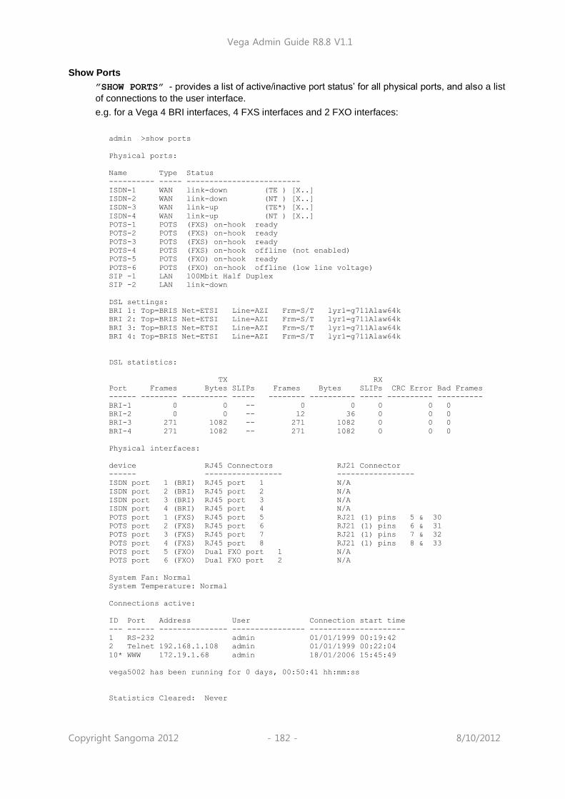
Vega Admin Guide R8.8 V1.1
Copyright Sangoma 2012 - 182 - 8/10/2012
Show Ports
”SHOW PORTS” - provides a list of active/inactive port status‟ for all physical ports, and also a list
of connections to the user interface.
e.g. for a Vega 4 BRI interfaces, 4 FXS interfaces and 2 FXO interfaces:
admin >show ports
Physical ports:
Name Type Status
---------- ----- -------------------------
ISDN-1 WAN link-down (TE ) [X..]
ISDN-2 WAN link-down (NT ) [X..]
ISDN-3 WAN link-up (TE*) [X..]
ISDN-4 WAN link-up (NT ) [X..]
POTS-1 POTS (FXS) on-hook ready
POTS-2 POTS (FXS) on-hook ready
POTS-3 POTS (FXS) on-hook ready
POTS-4 POTS (FXS) on-hook offline (not enabled)
POTS-5 POTS (FXO) on-hook ready
POTS-6 POTS (FXO) on-hook offline (low line voltage)
SIP -1 LAN 100Mbit Half Duplex
SIP -2 LAN link-down
DSL settings:
BRI 1: Top=BRIS Net=ETSI Line=AZI Frm=S/T lyr1=g711Alaw64k
BRI 2: Top=BRIS Net=ETSI Line=AZI Frm=S/T lyr1=g711Alaw64k
BRI 3: Top=BRIS Net=ETSI Line=AZI Frm=S/T lyr1=g711Alaw64k
BRI 4: Top=BRIS Net=ETSI Line=AZI Frm=S/T lyr1=g711Alaw64k
DSL statistics:
TX RX
Port Frames Bytes SLIPs Frames Bytes SLIPs CRC Error Bad Frames
------ -------- ---------- ----- -------- ---------- ----- ---------- ----------
BRI-1 0 0 -- 0 0 0 0 0
BRI-2 0 0 -- 12 36 0 0 0
BRI-3 271 1082 -- 271 1082 0 0 0
BRI-4 271 1082 -- 271 1082 0 0 0
Physical interfaces:
device RJ45 Connectors RJ21 Connector
------ ----------------- -----------------
ISDN port 1 (BRI) RJ45 port 1 N/A
ISDN port 2 (BRI) RJ45 port 2 N/A
ISDN port 3 (BRI) RJ45 port 3 N/A
ISDN port 4 (BRI) RJ45 port 4 N/A
POTS port 1 (FXS) RJ45 port 5 RJ21 (1) pins 5 & 30
POTS port 2 (FXS) RJ45 port 6 RJ21 (1) pins 6 & 31
POTS port 3 (FXS) RJ45 port 7 RJ21 (1) pins 7 & 32
POTS port 4 (FXS) RJ45 port 8 RJ21 (1) pins 8 & 33
POTS port 5 (FXO) Dual FXO port 1 N/A
POTS port 6 (FXO) Dual FXO port 2 N/A
System Fan: Normal
System Temperature: Normal
Connections active:
ID Port Address User Connection start time
--- ------ --------------- ---------------- ---------------------
1 RS-232 admin 01/01/1999 00:19:42
2 Telnet 192.168.1.108 admin 01/01/1999 00:22:04
10* WWW 172.19.1.68 admin 18/01/2006 15:45:49
vega5002 has been running for 0 days, 00:50:41 hh:mm:ss
Statistics Cleared: Never

Vega Admin Guide R8.8 V1.1
Copyright Sangoma 2012 - 183 - 8/10/2012
For more details on the “Connections active” section, see 8.5 Logged on users.
Show ports for ISDN units includes a section on ISDN statistics, including the number of frames
and bytes sent and received, the number of synchronisation slips, CRC errors and bad frames observed (the counters can be reset to clear initial power on occurrences using clear stats):
admin >show ports
Physical ports:
Name Type Status
---------- ----- -------------------------
ISDN-1 WAN link-up (TE*) [X...............X...............]
ISDN-2 WAN link-up (NT ) [X...............X...............]
H323-1 LAN link-up (10Mbps)
ISDN statistics:
TX RX
Port Frames Bytes SLIPs Frames Bytes SLIPs CRC Error Bad Frames
------ -------- ---------- ----- -------- ---------- ----- ---------- ----------
ISDN-1 178 710 1 178 710 1 0 0
ISDN-2 178 710 0 178 710 0 0 0
Connections active:
ID Port Address User Connection start time
--- ------ --------------- ---------------- ---------------------
1 * Telnet 192.168.1.108 admin 01/01/1999 00:44:52
Vega100T1E1 has been running for 0 days, 00:44:56 hh:mm:ss
In the ISDN statistics RX slip indicates slip between the Vega and the ISDN device to which the Vega is attached. TX slip indicates slip between the internal Vega bus and the outgoing data. RX slip and TX slip indicate that the ISDN device attached to the trunk reporting the slip errors is not synchronised to the device providing the master clock to the Vega.
Statistics Cleared: Never means that ISDN statistics have never been cleared – instead of
Never date / time information may be displayed.
For PRI, BRI and CAS interfaces, against the trunk is an indicator of channels in use, similar to:
(TE*) [X...............X...............]
inside the round brackets there is an indication of whether the trunk is configured as NT or TE. One of the trunks will have a * within the brackets indicating that this trunk is “bus master”. Inside the square brackets the following symbols may be found:
X - channel reserved, either a D-channel (signalling) or a channel carrying frame synchronisation
data
. - a free media channel (B-channel)
? - an allocated media channel6 – currently direction information is not available (transient state)
I - an allocated media channel for an incoming call on this trunk
O - an allocated media channel for an outgoing call on this trunk
Status Sockets
”STATUS SOCKETS” - provides detailed, information about the current LAN socket connections
6 When initiating an ISDN call, Vega sends a setup with a „suggested channel‟ to use in it, use of that
channel is not confirmed until the Vega receives a setup ack ... which actually may request a change of channel ... but Vega reserves the channel to prevent it from being grabbed by any other call.

Vega Admin Guide R8.8 V1.1
Copyright Sangoma 2012 - 184 - 8/10/2012
Network Sockets Status:
Socket Type State Local Address Remote Address
------ ---- ----- ------------- --------------
2 TCP connected 127.0.0.1:2818 127.0.0.1:998
3 TCP connected 127.0.0.1:998 127.0.0.1:2818
4 UDP connecting 136.170.208.139:2132 0.0.0.0:0
5 UDP connecting 0.0.0.0:0 0.0.0.0:0
6 TCP connecting 0.0.0.0:80 0.0.0.0:0
7 TCP connecting 136.170.208.139:1720 0.0.0.0:0
10 TCP connecting 136.170.208.139:23 0.0.0.0:0
11 UDP connecting 0.0.0.0:161 0.0.0.0:0
14 TCP connected 136.170.208.139:23 136.170.208.111:1075
Total: 9 ( Max 408 ) TCP: 6 UDP: 3
Show lan routes
SHOW LAN ROUTES displays the routing table for the Vega.
For example:
admin >show lan routes
Routing table:
Flags: U/D:Up/Down G:Gateway S/D: Static/Dynamic N/H:Network/Host x:Rejected
Destination Gateway Flags Interface
----------- ------- ----- ---------
172.19.1.0 172.19.1.212 U SN LAN1
192.168.1.0 192.168.1.33 U SN LAN2
Default 192.168.1.100 UGSN LAN2
In this example, the first two entries show that the subnet 172.19.1.0 is accessed through LAN interface 1 (IP address 172.19.1.212) and that the subnet 192.168.1.0 is accessed through LAN interface 2 (IP address 192.168.1.33). The third entry shows that the default LANgateway (which is used for routing all data traffic which is not on one of these two subnets) is 192.168.1.100 and this is accessed via LAN interface 2.
Show Lancfg
”SHOW LANCFG” - provides a summary of the LAN configurations for the various IP applications
supported by the Vega.
Show lancfg takes a following identifier which specifies the information required. This is one of the following:
ftp
tftp
dns
ntp
all
Choosing an application type specifically gives more information than that displayed using „all‟.
e.g. show lancfg all
admin >show lancfg all
Routing table:
Flags: U/D:Up/Down G:Gateway S/D: Static/Dynamic N/H:Network/Host x:Rejected
Destination Gateway Flags Interface
----------- ------- ----- ---------
2.2.2.0 2.2.2.2 U SN LAN1
200.100.50.0 200.100.50.22 U SN LAN2

Vega Admin Guide R8.8 V1.1
Copyright Sangoma 2012 - 185 - 8/10/2012
Default 200.100.50.79 UGSN LAN2
FTP Configuration:
Server IP: 172.19.1.109
LAN profile: 2
TFTP Configuration:
Server IP: 172.19.1.109
DHCP settings from interface: 1
LAN profile: 2
NTP Configuration:
Server IP: 0.0.0.0
LAN profile: 1
DNS Configuration:
Server hierarchy:
[1]: 172.19.1.1
[2]: 172.19.1.2
e.g. show lan cfg ftp
admin >show lancfg ftp
FTP Configuration:
Server IP: 172.19.1.109
LAN profile: 2
LAN interface: 2
QoS profile: 2
Name: Voice
DiffServ/ToS: Def: 0x00 Sig: 0x00 Med: 0x00
Show Version
”SHOW VERSION” - provides firmware version, serial number / MAC address, hardware variant
information and also information about the code loads in the two code partitions in the Vega.
admin >show version
Vega100 (T1E1) Runtime System
Version: 08.02.04b
Built: Oct 9 2002 13:38:34 T013
Serial #:005058000026
Bootstrap System
Version: 1.05(0ws)
ISDN Interface
Version: ISDN T1/E1 card: FPGA version 1, modstate 0
FLASH Partition Information:
Partition 1: H.323 Firmware
Version: 08.01.04
Built: Oct 9 2002 16:34:34 T011
Partition 2: SIP Firmware (ACTIVE)
Version: 08.02.04b
Built: Oct 9 2002 13:38:34 T013
The following reports give more detailed system level information:

Vega Admin Guide R8.8 V1.1
Copyright Sangoma 2012 - 186 - 8/10/2012
Show Trace
”SHOW TRACE” - provides a detailed list of all calls in the gateway, with routing
information
admin >show trace
CALL TRACE:
[09] call state: AWAITING_DISCONNECT
call ref: 070000990014
calling party: IF 07:POTS 2[1] g711Alaw64k #TEL:07,DISP:port2vega1,NA
ME:port2vega1
called party: #TEL:201
ongoing dest: IF 99:SIP 1[1] #TEL:201,TA:192.168.1.106
last event-7: POTS CC_SETUP_IND, ROUTE_IDLE
last event-6: DSP 13878, AWAITING_DTMF_DIALING
last event-5: DSP 2, AWAITING_DTMF_DIALING
last event-4: DSP 99, AWAITING_DTMF_DIALING x5
last event-3: TIMR 1, AWAITING_DTMF_DIALING
last event-2: SIP CC_SETUPACK_IND, AWAITING_ONGOING_CONN
last event-1: DSP 99, AWAITING_ONGOING_CONN
last event : SIP CC_DISCONNECT_IND, AWAITING_ONGOING_CONN
Summary of call states:
ROUTE_IDLE =0 AWAITING_DTMF_DIALIN=0 AWAITING_ONGOING_CON=0
AWAITING_INCOMING_CO=0 ROUTE_CONNECTED =0 AWAITING_DISCONNECT =1
AWAITING_PROGRESS_DI=0 AWAITING_MWI_SENDING=0
Show Stats
”SHOW STATS” - provides a snapshot of network statistics and memory usage
admin >show stats
NETWORK STATS:
RxD: inuse/max/total = 0/0/255. TxD: inuse/max/total = 0/5/254 TxB: temp/alloc/
total = 0/0/254
NIC: txstat: slowf=468 fastf=960 bytes=253503
NIC: err=0 jit=0 unf=0 smiss=0 amiss=0 gmiss=0
NIC: rxstat: slowf=7784 fastf=941 bytes=777255
NIC: err=0 crc=0 col=0 ovf=0 cmiss=0 smiss=0 phys=0
MEDIA STATS:
Media Packets Transmitted = 2041, dropped = 0 (0.00%)
Media Packets Received = 941, dropped = 0 (0.00%)
MEMORY STATS:
Total RAM present: 67108864 (65536K) [0x80000000-0x84000000]
Code/ROM data used: 7396368 ( 7223K) [0x80040000-0x8074dc10]
System Memory Pool: 59449328 (58055K) [0x8074dc10-0x83fffc00]
System Pool available: 53055420 (51811K)
System Pool used: 6393908 ( 6244K) = 10% used
System Memory Pool Low: 258048 ( 252K) [0x80001000-0x80040000]
Low Memory available: 0 ( 0K)
Low Memory used: 258048 ( 252K) = 100% used
Uncached Memory Pool: 851968 ( 832K) [0x805c9db0-0x80699db0]
Uncached Pool available: 65360 ( 63K)
Uncached Pool used: 786608 ( 768K) = 92% used
Config Memory Pool: 700000 ( 683K) [0x806a2db0-0x8074dc10]
Config Pool available: 249296 ( 243K)
Config Pool used: 450704 ( 440K) = 64% used
SNMP Memory Pool: 36864 ( 36K) [0x80699db0-0x806a2db0]
SNMP Pool available: 4804 ( 4K)
SNMP Pool used: 32060 ( 31K) = 86% used
ENTITY STATS:
System idle time = 7 %
ID Entity In use Max used Hi mark Lo mark Capacity Hi delay Hi loop Loop %

Vega Admin Guide R8.8 V1.1
Copyright Sangoma 2012 - 187 - 8/10/2012
-- -------- -------- -------- -------- -------- -------- -------- -------- ----- ---
0 INTSVC -- -- -- -- -- -- 0 0
1 SYSTIMER -- -- -- -- -- -- 0 0
2 CONSOLE 0 0 12 8 20 0 0 0
3 TELNET 0 1 60 40 100 137 3 0
4 LANPROXY -- -- -- -- -- -- 18 0
5 LAN 0 1 90 60 150 28 13 0
6 DSP 0 0 72 48 120 0 2 3
7 DSPDOWN -- -- -- -- -- -- 0 0
8 ROUTER 0 1 120 80 200 8 4 0
9 LOGGER 0 1 30 20 50 0 3 0
10 REDIRECT 0 0 1862 1241 3102 0 0 0
11 LCD 0 5 30 20 50 11305 5260 10
12 TPKT 0 0 60 40 100 0 0 0
13 MEDIA 0 0 36 24 60 0 0 0
14 WATCHDOG -- -- -- -- -- -- 0 0
15 BACKGND -- -- -- -- -- -- 1646 41
16 SNMP 0 3 12 8 20 17368 4984 43
17 PACING 0 1 36 24 60 0 0 0
18 WEBSERV 0 0 6 4 10 0 32 0
19 RFC2833 -- -- -- -- -- -- 0 0
21 SIP 0 37 90 60 150 18418 183 0
22 ISDNDVR -- -- -- -- -- -- 0 0
23 ISDN 0 1 90 60 150 47 14 0
24 TN -- -- -- -- -- -- 0 0
MESSAGING STATS:
MsgID 1stKey LastKey Name Size Capacity In use Max used
-------- -------- -------- ------------- ----- -------- ------ --------
f1000010 1001d 10028 CALL_CONTROL 436 250 0 3
f1000004 20008 20014 MC_IND 124 200 0 1
f1000007 30015 30016 MG_IND 40 200 0 0
f1000002 40002 40007 SYSTEM_CTRL 208 100 0 8
f100000f 50017 5001c LAN_MESSAGE 64 1652 1 3
f1000001 60001 60001 TIMER_EXPIRE 52 400 0 37
f1000011 70029 70035 ISDNDVR_IND 368 100 0 2
SOCKET STATS:
Protocol In use Max used Capacity
-------- -------- -------- --------
TCP 4 6 272
UDP 2 3 136
SOCKETS 10 - 408
NETWORK BUFFER STATISTICS:
in use=4 max used=33 capacity=1500
VEGA100 has been running for 0 days, 02:24:41 hh:mm:ss
Total number of calls: 4 [Completed: 0]
--------TN MEMORY STATISICS --------
# of used blocks: 446
# of free blocks: 2
Largest block size: 2260
Smallest block size: 40
Total used space: 73740
Total free space: 254260
single unit blocks: 0
zero unit blocks: 0
zero unit blocks: 0
Tot. inspections: 120
Tot. # requests: 120
Avg. inspections: 1
Max. inspections: 1
Max memory used: 73840

Vega Admin Guide R8.8 V1.1
Copyright Sangoma 2012 - 188 - 8/10/2012
Show Syslog
”SHOW SYSLOG” - shows the SYSLOG settings and status.
admin >show syslog
SYSLOG STATS
Server IP Mode Attempts Errors
---------------- ---------------- ----------------------------------- -------- --------
Main_Server 192.168.1.2 log | bill | console 15 0
My_PC 192.168.1.78 log | bill 8 0
Eng_laptop 192.168.1.66 debug 2 0
Attempts = Number of Syslog messages prepared for sending
Errors = Number of Syslog messages that failed to be sent, e.g. because of internal
resources or the configured IP address has „no route to destination‟. (Because UDP Syslog does not support handshaking, the fact that there are zero errors does not guarantee that the Syslog server has received all the messages.)

Vega Admin Guide R8.8 V1.1
Copyright Sangoma 2012 - 189 - 8/10/2012
Showdsp
”SHOWDSP” - shows the DSP channels‟ status – also the builds of DSP code loaded
and their echo tail size capabilities.
In the example below a call is in progress on Channel 0.
admin >showdsp
Available DSP Image Builds
--------------------------
Build: AC5; Longest Echo Tail: 64ms; Max Channels: 6/12
CODECS: G729,G729AnnexA,G711Alaw,G711Ulaw,T38,Clear
Build: AC4; Longest Echo Tail: 128ms; Max Channels: 5/5
CODECS: G729,G729AnnexA,G723.1,G711Alaw,G711Ulaw,T38,Clear
Ch Status InUse Image A/ULaw Ver PCmds TS Mode Codec
-- ------ ----- ----- ------ --- ----- --- ----- ----------
00 READY N AC5 A 9 0 000 VOICE G7231
01 READY N AC5 A 9 0 000
02 READY N AC5 A 9 0 000
03 READY N AC5 A 9 0 000
04 READY N AC5 A 9 0 000
05 READY N AC5 A 9 0 000
06 READY N AC5 A 9 0 000
07 READY N AC5 A 9 0 000
08 READY N AC5 A 9 0 000
09 READY N AC5 A 9 0 000
0A READY N AC5 A 9 0 000
0B READY N AC5 A 9 0 000
10 READY N AC5 A 9 0 000
11 READY N AC5 A 9 0 000
12 READY N AC5 A 9 0 000
… etc
69 READY N AC5 A 9 0 000
6A READY N AC5 A 9 0 000
6B READY N AC5 A 9 0 000
70 READY N AC5 A 9 0 000
71 READY N AC5 A 9 0 000
72 READY N AC5 A 9 0 000
73 READY N AC5 A 9 0 000
74 READY N AC5 A 9 0 000
75 READY N AC5 A 9 0 000
76 READY N AC5 A 9 0 000
77 READY N AC5 A 9 0 000
78 READY N AC5 A 9 0 000
79 READY N AC5 A 9 0 000
7A READY N AC5 A 9 0 000
7B READY N AC5 A 9 0 000
The Ch column (Channel number) is one (or more) digit(s) representing the DSP core that the DSP resource is in and the last digit is the resource ID within that core. The number of resource IDs varies depending on the DSP code loaded. Max Channels indicates the number of resources the code will allow in a DSP core.

Vega Admin Guide R8.8 V1.1
Copyright Sangoma 2012 - 190 - 8/10/2012
Dspdiag
”DSPDIAG” - requests detailed diagnostic statistics from a specific DSP channel
Command format:
DSPDIAG <function> <channel>
<channel> - to select the appropriate DSP channel use SHOWDSP.
<function>:
RAW - for engineering use only
VSTATS - average delay, jitter etc. statistics
ERROR - lost, dropped packets etc. statistics
RXTX - packet counts
LEVELS - show instantaneous transmit and receive power levels
FMSTATS - for engineering use only
FSTATS - for engineering use only
FCSTATS - for engineering use only
VALL - VSTATS, ERROR, RXTX and LEVELS in 1 command
FALL - error statistics
To look at voice statistics, also look at 0 QoS (Quality of Service) CDRs
admin > dspdiag vstats 0
Channel 0, Diagnostics (VOICE Stats)
----------------------- ---------------
AvDlay= 26 LostCt= 0 ReplCt= 0 RxSgCt= 101
AvJit = 3 IdleCt= 47423 DropCt= 0
ApbInc= 0 ApbDec= 0 CseCt = 0 PbuCt = 0
admin > dspdiag error 0
Channel 0, Diagnostics (ERROR Stats)
----------------------- ---------------
LostEnhVcePkt = 0 DropEnhVcePkt = 0
InvalidHdrCt = 0 VoiceBufOver = 0
admin > dspdiag rxtx 0
Channel 0, Diagnostics (RXTX Stats)
----------------------- ---------------
RxPktsPl = 94 TxPkts = 183 SilPktsTx= 47949 FrameDrop= 0
MinPktArr= 20 MaxPktArr= 40 AvPktArr = 69
admin > dspdiag levels 0
Channel 0, Diagnostics (LEVELS)
----------------------- ---------------
RxPower = -52.0dBm, TxPower = -49.0dBm
admin > dspdiag vall 0
Channel 0, Diagnostics (VOICE Stats)
----------------------- ---------------
AvDlay= 26 LostCt= 0 ReplCt= 0 RxSgCt= 101
AvJit = 3 IdleCt= 50967 DropCt= 0
NOTE

Vega Admin Guide R8.8 V1.1
Copyright Sangoma 2012 - 191 - 8/10/2012
ApbInc= 0 ApbDec= 0 CseCt = 0 PbuCt = 0
Channel 0, Diagnostics (ERROR Stats)
----------------------- ---------------
LostEnhVcePkt = 0 DropEnhVcePkt = 0
InvalidHdrCt = 0 VoiceBufOver = 0
Channel 0, Diagnostics (RXTX Stats)
----------------------- ---------------
RxPktsPl = 0 TxPkts = 0 SilPktsTx= 3005 FrameDrop= 0
MinPktArr= -1 MaxPktArr= 0 AvPktArr = 69
Channel 0, Diagnostics (LEVELS)
----------------------- ---------------
RxPower = -51.0dBm, TxPower = -48.0dBm
admin > dspdiag fall 0
Channel 0, Diagnostics (ERROR Stats)
----------------------- ---------------
LostEnhVcePkt = 0 DropEnhVcePkt = 0
InvalidHdrCt = 0 VoiceBufOver = 0
Nomenclature:
AvDlay = Average Delay
LostCt = Lost Count
ReplCt = Replay Segment Count (where multiple segments are sent in a packet e.g. g7231)
RxSgCt = Received Segment Count (where multiple segments are sent in a packet e.g. g7231)
AvJit = Average Jitter
IdleCt = Idle Segment Counter – number of "idle segments" received (directly related to "idle packets") DropCt = Dropped packets count
ApbInc = Adaptive Playout Buffer - delay increase counter ApbDec = Adaptive Playout Buffer - delay decrease counter CseCt = Counter of cell starvation events PbuCt = Playout Buffer Underflow Counter
LostEnhVcePkt = Lost Enhanced (FRF.11) Voice packets
DropEnhVcePkt = Dropped Enhanced (FRF.11)Voice packets
InvalidHdrCt = Invalid Header Count
VoiceBufOver = Voice Buffer Overflow
RxPktsPl = Received Packets Played
TxPkts = Transmitted packets
SilPktsTx = Silence packets transmitted
FrameDrop = Frames dropped
MinPktArr = Min inter-packet arrival time MaxPktArr = Max inter-packet arrival time
AvPktArr = Average inter-packet arrival time
RxPower = Receive Power
TxPower = Transmit Power
10.3 Show Support
”SHOW SUPPORT” - this command automatically executes a large number of “show”
commands so that detailed information about the status of the Vega can be obtained from a single command.

Vega Admin Guide R8.8 V1.1
Copyright Sangoma 2012 - 192 - 8/10/2012
The commands that it executes (on a SIP unit) are:
SHOW BANNER SHOW REBOOT SHOW LOG
SHOW VERSION SHOW PORTS SHOW PLAN
SHOW IP SHOW LANCFG SIP UA SHOW TRACE
POTS SHOW TRACE SIPPROXY SHOW REG SIP SHOW REG
SIP SHOW TRACE ISDN SHOW TRACE SHOW POST PATHS
SHOW LAN ROUTES CADENCE SHOW TRACE DEBUG TONE STATUS
SHOW QOS STATS SHOW _ADVANCED
CHANGES
RFC2833 SHOW
TRACE
SHOW TIME STATUS SUPPSERV STATUS SIPPROXY
SIPPROXY STATUS SHOW TRACE SHOW SYSLOG
SHOW MHASH STATUS NAT STATUS TERMS
SHOW BILL SHOW CHANGES SHOW HIGHWAY
SHOW STATS SHOW WARNINGS SHOW CALLS
SHOW HOSTS SHOW ARP HIGHWAY CHECK
SHOW THIRD PARTY STATUS SOCKETS STATUS BUFFERS
ESUP SEM HLIST
SHOW PATHS SHOWDSP SPUT
The Show Support command is especially important to use prior to raising a technical support enquiry. A copy of the results of this command will provide the support engineer with useful details of the status and configuration of the Vega.
10.4 CDRs – Call Detail Records
Call detail records are available for billing and for quality of service information. Billing data may be obtained from the Vega either through the serial or telnet interfaces, or via Radius accounting records. Quality of service information is available from the serial or telnet interfaces.
CDR Billing via serial / telnet
The Billing log buffer stores call detail records that are generated on termination of each call.
A filter can be specified to either LOG only non-zero duration call records (good calls) – BILL ON,
or all records (including those for calls which end as Busy or Number Unobtainable) – BILL Z.
The log can be turned off by typing BILL OFF, and cleared by typing BILL CLEAR.
The log can be displayed either by enabling the display to the console (which displays the call log
immediately the call terminates) using BILL DISPLAY ON, or display the whole log buffer by
typing SHOW BILL. The latter displays a summary for each line of the log.
An alert threshold can be configured such that a warning event is issued at the configured buffer occupancy level (bill_warn_threshold).
For further details on billing CDRs, see Information Note “IN 01 – Billing”
CDR Billing via Radius accounting records
Vegas can use Radius Accounting records to deliver billing CDR information.
Vega Admin Guide R8.8 V1.1
Copyright Sangoma 2012 - 193 - 8/10/2012
Radius accounting records with “overloaded acct_session_ID” fields are used to carry the CDR data (Vegas do not use the Vendor specific attributes field). One of two data formats may be selected for the call sequence string, one which matches Cisco‟s record format for easy integration into systems that already incorporate Cisco equipment, and the second a Vega format which matches the data provided in the telnet and serial CDR format.
CDR records are sent as calls start and stop. If the Cisco format is chosen, separate records are sent for each leg of the call (i.e. for a call through a Vega there will be a start and a stop record for the call as it enters the Vega and also for the call as it exits the Vega – two start records and 2 stop records).
The Vega can be configured with up to 2 Radius servers, which it uses in Master / Backup order. On power up or reboot, if any radius billing server is enabled in the Vega parameters it will send an Accounting On record (registration message) to the first enabled server. If a server fails (replies timeout) the Vega will try registering with the other server (if it is enabled). If it receives a response to the registration it will send the CDR records to this server (Accounting start and Accounting stop messages). If no reply is received it will keep hunting for a server.
The Radius Accounting Records are sent as UDP datagrams.
The following parameters are used to configure Radius on the Vega:
[logger.radius]
format=cisco_overload ; Select desired format of Radius Accounting
record, vega_overload or
cisco_compatible_overload
retries=4 ; Max retries used to send a specific accounting
message, 1 to 100
retry_time=5000 ; Initial timeout before retry (milliseconds), 1 to
5000 (time doubles for each retry but limits
at max_retry_time)
max_retry_time=4000 ; Maximum retry timer for retransmissions
(milliseconds), 1 to 40000
window_size=10 ; Maximum number of accounting messages that can be
sent to the server before receiving a response, 1
to 256
name=Vega_VoIP_Gtaeway ; NAS (Network Access Server – gateway) identifier
[logger.radius.server.1]
enable=0 ; Disable or enable use of this radius server, 0 or
1
ipname=0.0.0.0 ; IP address or DNS resolvable name of the radius
server
port=1813 ; UDP port used to receive radius data on the
server, 1 to 65535
secret=Testing123 ; Shared secret encryption string – must be
configured on the radius server too, length <= 31
characters
[logger.radius.server.2]
…
For further details on Radius accounting CDRs, see Information note “IN 07 – Radius Accounting”

Vega Admin Guide R8.8 V1.1
Copyright Sangoma 2012 - 194 - 8/10/2012
QoS (Quality of Service) CDRs
From Release 6, per-call and per-gateway logs of QoS statistics may be obtained. Like CDR billing records, the Vega has an internal buffer into which it writes the last n per-call QoS CDRs. By connecting to the Vega via telnet or via a serial connection, these can be collected live as they are generated.
For details on configuring the Vega and the format of the resulting QOS CDR records, see information note “IN 15 QOS Statistics”

Vega Admin Guide R8.8 V1.1
Copyright Sangoma 2012 - 195 - 8/10/2012
11 CONFIGURATION FOR E1T1 AND BRI VEGAS
11.1 System Variants
Vega 100s, 200s and 400s are equipped with E1T1 links, Vega 50 Euopas can be equipped with BRI links.
The parameters for configuring the above products are largely the same. Those parameters that are common across all signalling schemes are documented in the following section. Specific configuration for ISDN, QSIG, and RBS CAS are documented in successive sections.
11.2 General Configuration for E1T1 AND BRI Vegas
Network Type, Topology and Line Encoding
The Network type and Line Encoding values available are dependent on the Topology being used (E1, T1, or BRI), and are set in the following parameters:
[e1t1/bri]
network=ETSI|NI|ATT|DMS|QSIG|DMS_M1|RBS
topology=S|E1|T1
line_encoding=B8ZS|AMI|HDB3|AZI
framing=ESF|SF|CRC4|PCM30
Specific configuration for the different network types are handled in their own specific sections:
network= ETSI|NI|ATT|DMS|DMS_M1 are handled in section 11.3 “ISDN Specific Configuration”,
network=QSIG is handled in section 11.4 ” QSIG Specific Configuration”, and
network=RBS is handled in section 0 “HLC / LLC Tunnelling
Vega ISDN gateways can tunnel HLC and LLC ISDN IEs to between ISDN and SIP and viceversa. The HLC and LLC IE is passed using a MIME object in the SIP INVITE message. The HLC and LLC IEs are passed in the SDP, with the LLC information element coded first, and the HLC information element coded second to respect the order of appearance specified in Q.931, as per the message below:
SIP m:0579233 -1313560 00189<-- UA RX --- From UDP(20):172.19.1.227:5060
INVITE sip:[email protected]:5060 SIP/2.0
Via: SIP/2.0/UDP 172.19.1.227:5060;branch=z9hG4bK-1-0
From: sipp <sip:[email protected]:5060>;tag=1
To: sut <sip:[email protected]:5060>
Call-ID: [email protected]
CSeq: 1 INVITE
Contact: sip:[email protected]:5060
Max-Forwards: 70
Subject: Performance Test
Content-Type: multipart/mixed;boundary=zv8az81nna8aaannnkllwqpqp
Content-Length: 248
--zv8az81nna8aaannnkllwqpqp
c: application/vnd.cirpack.isdn-ext
7c0311c11c
--zv8az81nna8aaannnkllwqpqp
v=0
o=user1 53655765 2353687637 IN IP4 172.19.1.227
s=-
c=IN IP4 172.19.1.227
t=0 0
m=audio 6000 RTP/AVP 0
a=rtpmap:0 PCMU/8000
The following parameter controls this behaviour:

Vega Admin Guide R8.8 V1.1
Copyright Sangoma 2012 - 196 - 8/10/2012
_advanced.sip.q931.tx_tun_mode
Possible values:
off – Default – Do not tunnel HLC / LLC
cirpack – Tunnel HLC / LLC as described above
req_uri – Not applicable to HLC / LLC
CAS T1 Specific Configuration”.
Companding Type
The companding or PCM-type type used on the E1T1/BRI for the specific country/switch type is configured in:
[e1t1/bri.port.n]
lyr1=g711Alaw64k | g711ulaw64k
A-law is typically used in Europe, and u-law is used in the USA.
B-channel Grouping
The ISDN port interfaces can be configured to support logical B-channel clustering if required – using the groups facility. This facility effectively assigns a unique interface ID (IF:) to a single B-channel or group of B-channels. This means that each physical ISDN can be split into a number of different interface IDs (IF:s) to specify from the dial planner which B-channel (or B-channel group) to use when making the outgoing call; also the appropriate IF: will be presented to the dial planner when a call arrives from a specific B-channel. B channel grouping can have overlapping channels, and this can, for example, be used to extend the number of DNs (directory numbers) allocated to a physical ISDN (for outgoing calls).
[e1t1/bri.port.n.group.m]
interface=01
cost=9
dn=5551000
first_chan=1
last_chan=30
By default each E1T1/BRI has only one interface ID or group assigned to it; this covers all available B-channels, i.e. for E1 Vegas last_chan=30, for T1 PRI Vegas last_chan=23 and for T1 CAS Vegas last_chan=24.
For example, to set up an interface ID, IF:35, which will send calls on channels 3 to 5, and will present a caller ID 1234567 use the following:
[e1t1/bri.port.n.group.m]
interface=35
cost=0
dn=1234567
first_chan=3
last_chan=5
Interface Ids must be unique within a single Vega. Maks sure that as you create a new group you assign it a new and unique interface ID.
B-channel Allocation Strategies
In order to minimise the number of times at which the two ends of a ISDN LINK clash by choosing the same channel to try and present a call on, the channel allocation strategy can be configured on the Vega.
NOTE

Vega Admin Guide R8.8 V1.1
Copyright Sangoma 2012 - 197 - 8/10/2012
Linear up mode (selecting the lowest free channel on the ISDN) – this should be selected if the far end is configured for linear down
Linear down mode (selecting the highest free channel on the ISDN) – this should be selected if the far end is configured for linear up
Round Robin mode (selecting the next free channel on the ISDN 1..last_chan then back
to 1 again) – this should be selected if the far end is configured for round robin
Default – for easy configuration this will use linear up if the ISDN is configured as NT, and Linear down if the ISDN is configured as TE.
[e1t1/bri.port.n.group.m]
alloc_chan=default|linear_up|linear_down|round_robin
Inband progress tones
See section 0, Selecting Generation of Progress Tones vs Media Pass Through.
Cause code mapping
When ISDN, RBS CAS, H.323 and SIP calls are cleared down a “cause code” is generated which identifies the reason for the call cleardown – a list of cleardown cause codes may be found in Information Note IN 18. Typically if a call clears for a particular reason the Vega will pass that reason code on as the reason for clearing. There are however times at which the Vega may need to modify the cause code value it sends on. For instance if the Vega bridges two neworks, where one network supports a smaller set of cleardown cause codes than the other, the Vega will have to map outlying cause codes onto valid cause codes.
The Vega can apply a cause code mapping to cause codes sent out over the (ISDN or RBS CAS) telephony interfaces. Cause code mapping tables are configurable through the web browser using the advanced>show_cause_mapping menu or via the CLI parameters
[_advanced.outgoing_cause_mapping.x]
name = <name> ; name parameter for self documentation purposes
c1=1 ; mapping for cause code 1 (by default = 1)
c2=2 ; mapping for cause code 2 (by default = 2) … etc.
…
c127=127
From Release 7.5, the Vega can also apply a cause code mapping to cause codes received from the (ISDN or RBS CAS) telephony interfaces. Cause code mapping tables are configurable through the web browser using the advanced>show_cause_mapping menu or via the CLI parameters:
[_advanced.incoming_cause_mapping.x]
name = <name> ; name parameter for self documentation purposes
c1=1 ; mapping for cause code 1 (by default = 1)
c2=2 ; mapping for cause code 2 (by default = 2) … etc.
…
c127=127
Cause code mappings are set up by altering the cause code parameters away from the 1:1 relationship (c1=1, c2=2 … etc.) which is the default configuration. If a call comes in with a
cleardown cause code of 2, for instance, then the Vega will look up parameter c2 and will pass on
the value that has been assigned to it as the cleadown cause code.

Vega Admin Guide R8.8 V1.1
Copyright Sangoma 2012 - 198 - 8/10/2012
Each ISDN interface can be configured to map or not to map cause codes using:
[e1t1/bri.port.n.isdn]
incoming_cause_mapping_index=x ;incoming mapping table to use
outgoing_cause_mapping_index=x ;outgoing mapping table to use
x defines the _advanced.cause_mapping.x mapping table to use. If x = 0 then no mapping
is performed.
The mapping table to use for each ISDN interface may be configured through the web browser using:
e1t1/bri>Port Configuration “Modify”> e1t1/bri_configuration >ISDN Configuration> cause_mapping
Bus master
The bus_master_priority configuration parameter defines which trunk the Vega uses to
synchronise its internal clock.
The Vega receives a clock on ports configured as clock_master = 0 (Vega E1T1) and as nt=0
(Vega 50 BRI). The bus_master_priority parameter should be configured to prioritise the
clock receiver trunks in the order that they should be used for synchronising the Vega internal clock.
For further details on configuring bus master, see Information Note “IN 03 – ISDN Clocks”
Vega E1T1 Bypass Relays
For more information on this feature refer to Information Note “IN 44 – Vega 400 Bypass Relays”
Newer Vega 100, 200 and 400 models are fitted with fallback relays such that in the event of power failure or intervention by maintenance personnel the E1T1 connections become metallically connected to a second set of RJ45 connectors.
The diagram below shows a typical install where the fallback relays could be in use:
The status of the ISDN fallback relays can determine whether SIP registration takes place on a Vega E1T1 (models where ISDN fallback relays are fitted).
The slave Vega can be configured such that it will only transmit SIP REGISTER messages when its DSL‟s become active. This would happen if the master Vega loses power, is upgraded or is manually put into bypass mode.
Parameter: sip.reg_mode
Possible values: normal – Default – Existing behaviour, Vega will register any
configured SIP users
pbx
MASTER SLAVE
Vega Admin Guide R8.8 V1.1
Copyright Sangoma 2012 - 199 - 8/10/2012
on_ISDN_active – Vega will only register users when any DSL is active
Specific T1 configuration
11.2.1.1 T1 Line matching
For the Vega T1 product the transmit equalisation for the ISDN trunks needs to be configured. This is achieved on a per trunk basis using:
[e1t1/bri.port.x]
t1_tx_equalization=<tx_equ>
<tx_equ> can take the following values:
lhlbo0 (long haul line build out 0 dB)
lhlbo7_5 (long haul line build out -7.5 dB)
lhlbo15 (long haul line build out -15 dB)
lhlbo22_5 (long haul line build out -22.5 dB)
sh0_110 (short haul 0-110 ft.)
sh110_220 (short haul 110-220 ft.)
sh220_330 (short haul 220-330 ft.) - default setting
sh330_440 (short haul 330-440 ft.)
sh440_550 (short haul 440-550 ft.)
sh550_660 (short haul 550-660 ft.)
Long haul values are used where the distance between the Vega and the closest repeater or other ISDN endpoint is greater than 660 feet. Short haul value lengths are the distance between the Vega and the closest repeater or other ISDN endpoint.
The t1_tx_equalization setting is only applicable in T1 mode
(topology=t1); in E1 mode t1_tx_equalization is ignored.
E1 systems have their own equalization setting e1_rx_short_haul
11.2.1.1.1 Guidelines for configuring t1_tx_equalization:
For short haul the aim is to make sure that the shape of the waveform at the receiver is as perfect as possible; changing the parameter alters the shape of the waveform generated by the Vega (to compensate for the additional capacitance of longer lines). Match the parameter value to the line lengths indicated in the above table. If the length is not known, then start using the value
sh220_330.
For long haul (> 660 feet) the waveshape is not altered any further; the configuration parameter affects the amplitude of the signal. The aim is to tune the transmit amplitude such that the receiver receives a signal slightly above –36dB below the maximum signal strength (the 0dBm value). If the transmitted amplitude is too high, cross-talk can be introduced onto other lines, if too low it will not be reliably detected. If it is not possible to measure the received amplitude then it is best to
start by setting the value to lhlbo0.
Specific E1 configuration
11.2.1.2 E1 Line matching
For the Vega E1 product the receiver sensitivity needs to be configured based on the line length between the Vega and the closest repeater or other ISDN endpoint.
The configuration is achieved using:
NOTE

Vega Admin Guide R8.8 V1.1
Copyright Sangoma 2012 - 200 - 8/10/2012
[e1t1/bri.port.n]
e1_rx_short_haul=0 or 1 ; 0=long haul and 1=short haul
Long haul should be selected when the cable between the Vega and the closest repeater or other ISDN endpoint introduces more that 6dB attenuation.
Short haul should be selected when the cable between the Vega and the closest repeater or other ISDN endpoint introduces less than or equal 6dB attenuation.
11.3 ISDN Specific Configuration
Introduction
ISDN signalling is a CCS (Common Channel Signalling) scheme, which means that it uses messages in the „D‟ channel to signal call states. With a message based structure, many useful indicators can be passed, including information like DDI, DNIS, Answer and Disconnect.
ISDN Network Type, Topology and Line Encoding
The following table can be used as a guide when setting up parameters for ISDN installations:
Product Physical Connection
Topology Network E1T1/BRIs
Line Encoding Framing Calls
Vega 100, 200, 400 E1:
E1-2.044 Mbps E1 Euro ISDN 4 HDB3 CRC4 / PCM30
8 to 120
T1: T1-1.544 Mbps T1 NI2, AT&T 5ESS, DMS, DMS_M1
4 B8ZS / AMI SF(=D4) / ESF
8 to 92
Vega 50 Europa S/T 384 Kbps S Euro ISDN 2, 4 or 8
AZI - 4, 8 or 16
11.3.1.1 DMS-Meridian-specific ISDN setting (SIP builds only)
The e1t1/bri.network configuration parameter has been extended to include dms_m1. This is
the selection required when connecting a SIP Vega E1T1 to a Meridian PABX.
The protocol implemented for this selection is identical to DMS100 (network=dms) with the one
exception:
The final Channel Number Octet of the Channel ID Information Element is set to a „0‟ and not „1‟.
NT/TE Configuration
Each ISDN physical interface or E1T1/BRI (digital subscriber line) can be software configured to be either the TE (Terminal Equipment) or NT (Network Termination) end. This enables the Vega to be used in multiple scenarios, i.e. trunks plugged into a CO (Vega trunks configured as TE), trunks plugged into a PBX (the Vega acting as though it were a CO - Vega trunks configured as NT), or with one trunk plugged into the CO and one into a PBX. The latter scenario allows the Vega to be inserted into an existing telephony link between a CO and PBX and based on dial plan rules, it can either continue to pass calls between the PBX and the CO, or groom off some of the calls and route them on as VoIP calls.

Vega Admin Guide R8.8 V1.1
Copyright Sangoma 2012 - 201 - 8/10/2012
When configuring TE and NT, the value of the clock_master_priority parameter should also
be checked. Usually, if NT is set, then clock_master should also be set, and if NT is clear (TE
mode) then the Vega should be a clock slave (clock_master_priority=0).
The pinouts for TE and NT connections are different. On the Vega E1T1 the hardware pinouts change as TE or NT are selected. In this case a straight cable can in general be used to connect to the far end device.
Specific BRI configuration
1. Do not be surprised if, even after configuration, the L2 LED flashes indicating no layer 2 connection. Many BRI connections do not bring up layer 2 until a call is made.
2. Vega 50 BRI units all have 100 ohm termination impedances across their LINKSs. Ideally the Vega should be connected physically at the end of the LINKS.
11.3.1.2 BRI Point-to-Point Mode
Basic Rate ISDN lines (S0 bus interfaces) can be configured in one of two ways, either Point-to-Point or Point-to-Multipoint.
Point-to-Point (PP) is used
i when a Vega is connected to a BRI CO network line which is configured to support just one device connected directly to it (the Vega will be configured as TE) – e.g. ISDN data line connection.
ii when a Vega is the only device connected directly to a BRI PBX and is acting like a CO network (the Vega will be configured as NT).
Point-to-Multipoint (PMP) is used
i when a Vega is connected as the NT device connected to one or more ISDN telephones or other TE endpoints.
ii when a Vega is connected as an attached device to an S0 bus interface on a PBX or BRI CO network where ISDN telephones would normally be plugged
Devices that are connected together on a single BRI S0 bus must either: - all be configured as Point-to-Point or must - all be configured as Point-to-Multipoint.
The default mode of operation for the BRI product is to use Point-to-Multipoint mode (PMP) on all ports.
Each PORT of the Vega 50 BRI can be independently configured to use either Point-to-Point mode (PP) or Point-to-Multipoint mode (PMP) whether the PORT is configured as TE or NT.
In PP mode a maximum of one device at a time can be connected to each PORT. A fixed Terminal Endpoint Identifier (TEI) must be defined for the Vega PORT, and this must match the one configured in the corresponding device (typically configure TEI=0). Either the same or different TEIs may be defined for each physical PORT.
The configuration parameters to set up a fixed TEI to „xx‟ on PORT „n‟ are as follows:
[bri.port.n]
line_type=pp
tei=xx
NOTE
NOTE

Vega Admin Guide R8.8 V1.1
Copyright Sangoma 2012 - 202 - 8/10/2012
To revert the BRI back to Point-to-Multipoint mode (PMP) configure the parameter as follows:
[bri.port.n]
line_type=pmp
(In pmp mode the value of tei is ignored.)
11.3.1.3 BRI TE – Telephone number to accept
In a Point-to-Multipoint configuration the NT device may be connected to multiple TE devices. When a call arrives the NT device broadcasts the details of the call (including the called number) to the TE devices. Any TE device that is configured to accept calls for that number will start ringing. When a TE device answers the call, it locks out the other TE devices from this call and a 1:1 connection is made between the NT and the answered TE for the rest of the call.
If a Vega is one of the TE endpoints, then the parameter that configures which called number(s) it will respond to is:
[bri.port.x.group.y]
dn
If the value of dn matches the last digits of the called number then the Vega will try to handle the
call (it will use its dial plan to onward route the call).
By default dn=*, and so the Vega will respond to every call that is sent from the NT.
Example:
If ….1.group.1.dn=34 then the Vega will respond to calls on BRI 1 to:
01344 784 934, and
020 1234 34, etc.
but will not respond to:
01344 784 933, or
020 1234 35.
dn may take the value of *, or may be a sequence of digits.
11.3.1.4 BRI Layer 2 handling
In most signalling scenarios it is required that signalling layers come up in order and that if a layer fails, all layers are cleared down before being restarted. With certain BRI system implementations however, the network is configured to drop L2 when not in use (but not layer 1) – layer 2 is then re-established when a call is to be made. In this case it is valid to allow layer 2 to be re-established without layer 1 going down then up.
Vega 50 BRI units may be configured to only start layer 2 after layer 1 has just come up, or allow layer 2 to be re-established at any time after a layer 2 disconnect. The parameter is:
[_advanced.isdn]
restart_l2_after_disc=1 / 0
If set to 1 (default) the Vega 50 BRI allows re-establishment of layer 2 after a layer 2 disconnect has occurred.
If set to zero then establishment of layer 2 is only attempted if layer 1 has just come up.
11.3.1.5 BRI Phantom Power
Provided that at purchase time phantom power was specified, BRI gateways can be configured to provide phantom power on NT configured BRI ports. The following parameter controls this behaviour:
bri.port.1.nt_phantom_power=

Vega Admin Guide R8.8 V1.1
Copyright Sangoma 2012 - 203 - 8/10/2012
This parameter can take the following values:
0 – Default – Do not provide power
1 – Provide power
When phantom power is enabled each BRI interface provides 40V at a maximum current of 100mA.
Verifying ISDN IEs (Information Elements)
The ISDN stack in the Vega verifies that IEs found in the signalling match the relevant signalling specification. It verifies both the IE types, and also their content. Where the signalling does not completely adhere to the appropriate specification the Vega can be configured to disable this checking:
set _advanced.isdn.verify_IEs=0 disables checking of IE types (and contents of those IEs)
set _advanced.isdn.verify_IE_contents=0 disables checking of contents of IEs
See also section 11.5 “Tunnelling signalling data” for details on passing extra signalling information through the Vega.
Call Hold
When configured as NT, BRI gateways will respond to received ISDN HOLD or SUSPEND messages and will place the other call party on hold. The call will be taken off hold on reception of a RETRIEVE or RESUME message. Whilst the call is on hold the tone defined by
tones.suspended_seq will be played to the on-hold party.
11.4 QSIG Specific Configuration
Introduction
QSIG is a CCS (Common Channel Signalling) protocol similar to ISDN, though more tailored to PBX to PBX communications, supporting supplementary services that enable PBXs to pass information between themselves. Many of the same features and parameters used in configuring ISDN signalling are also used for configuring QSIG.
QSIG is supported on E1/T1 equipped Vegas, SIP Vegas support QSIG Basic Call handling; H.323 Vegas support both QSIG Basic Call handling and QSIG tunnelling.
By enabling QSIG Basic Call handling, this allows the Vega to operate at the Q-reference point to any Basic Call compliant device (PINX). In this mode the Vega can only send and receive the subset of Q.931 call control messages defined in the QSIG Basic Call Specification (ISO/IEC 11572).
From details on H.323, QSIG tunnelling, see 11.5 Tunnelling signalling data
QSIG Tunneling.
QSIG Network Type, Topology and Line Encoding
The following table can be used as a guide when setting up parameters for QSIG installations:
Product Physical Connection
Topology Network E1T1s
Line Encoding Framing Calls
Vega 100, 200, 400-PRI
E1-2.044 Mbps E1 QSIG 4 HDB3 CRC4 / 8 to

Vega Admin Guide R8.8 V1.1
Copyright Sangoma 2012 - 204 - 8/10/2012
E1: PCM30 120
T1 T1-1.544 Mbps T1 QSIG 4 B8ZS/AMI SF/ESF 8 to 92
11.4.1.1 E1 QSIG Operation
The following parameters are used to configure the interface:
[e1t1]
topology=E1
network=qsig
line_encoding=hdb3
framing=crc4/pcm30
[_advanced.isdn]
qsig_mode=contiguous/non_contiguous
11.4.1.1.1 E1 QSIG, Contiguous / Non-Contiguous Channel Mapping
QSIG User Channels (Uqs) can be numbered in two ways:
i) In a contiguous block, Uqs = 1..30 (Uq channels 1-15 map on to Timeslots 1..15, and Uq channels 16..30 map onto Timeslots 17-31).
ii) In a non-contiguous block, Uqs = 1..15 and 17..31 (Uq channels 1-15 map directly on to Timeslots 1..15, and Uq channels 17..31 map directly onto Timeslots 17-31).
The numbering scheme (qsig_mode) configured on the Vega must match the scheme used by
the QSIG device that the Vega is connected to.
11.4.1.2 T1 QSIG Operation
The following parameters are used to configure the interface:
[e1t1]
topology=T1
network=qsig
line_encoding=b8zs/ami
framing=esf/sf
11.4.1.2.1 T1 QSIG, Contiguous / Non-Contiguous Channel Mapping
Unlike E1, there is no similar concept of contiguous / non-contiguous mapping of QSIG user channels (Uqs).
For T1 Uqs always form a contiguous block, which maps directly onto the timeslots. (Uq channels 1..23 map onto Timeslots 1..23).
NT/TE or Master/Slave Configuration
Each E1T1 (digital subscriber line) can be software configured to be either QSIG master (A-side)
or QSIG slave (B-side). The nt configuration parameter is used to select the appropriate setting.
The Vega E1T1 should always be configured to be the opposite value to that configured on the attached QSIG device. (i.e. if attached QSIG device is Master, Vega must be set to slave).
[e1t1.port.n]
nt=1 ; QSIG, master or “A” side
[e1t1.port.n]
nt=0 ; QSIG, slave or “B” side

Vega Admin Guide R8.8 V1.1
Copyright Sangoma 2012 - 205 - 8/10/2012
In Vega statistics A-side is indicated as NT and B-side is indicated as TE.
When configuring A-side and B-side, the value of the clock_master parameter should also be
checked.
On E1T1 Vegas the hardware pinouts change as TE or NT are selected. In this case a straight cable in general can be used to connect to the far end device.
Overlap Dialling
See paragraph in 9.9 Overlap Dialling.
Type of Number configuration
Type of Number is configured as described in section 9.12 National / International Dialling – Type Of Number, but as the configuration was implemented for ISDN rather than QSIG, ISDN names need to be used when configuring QSIG PNP TON values. When configured for QSIG signalling the following mapping occurs:
Required QSIG PNP TON Binary Code Configuration value needed
(ISDN TON)
Unknown 0 0 0 Unknown
Level 2 Regional Number 0 0 1 International Number
Level 1 Regional Number 0 1 0 National Number
PISN specific number 0 1 1 Network-specific number
Level 0 Regional Number 1 0 0 Subscriber Number
Message Waiting Indication
The Vega can pass MWI (Message Waiting Indication) as follows:
SIP to QSIG (i.e. from a SIP IP voicemail system to legacy PBX)
QSIG to SIP (i.e. from legacy PBX to SIP)
Both standard and Ericsson proprietary message format is supported.
The following parameters are relevant for message waiting delivery:
Parameter: _advanced.isdn.mwi.type
Possible values: normal – Default - Use standard message format for MWI
ericsson – Use Ericsson proprietary message format
Parameter:
_advanced.isdn.mwi.ericsson.ASF_IE_ID
Possible values: Default 127 - Any value between 0 and 255
Parameter:
_advanced.isdn.mwi.ericsson.PBX_Protocol_ID
Possible values:
NOTE

Vega Admin Guide R8.8 V1.1
Copyright Sangoma 2012 - 206 - 8/10/2012
Default 254 - Any value between 0 and 255
Parameter:
_advanced.isdn.mwi.ericsson.system_ID
Possible values: Default 0 - Any value between 0 and 99
QSIG Un-Tromboning
Un-Tromboning, also known as TBCT (Two Bearer Channel Call Transfer), or call optimisation is supported on E1T1 Vegas running SIP firmware. Where a call has been established through the Vega then subsequently transferred or forwarded, the situation can exist where a trombone (or hairpin) exists between the Vega and PBX such that two bearer channels are taken up by a single call.
The following scenarios are supported:
Vega initiated un-tromboning, see diagram below. Un-tromboning initiated by the Vega on QSIG so that the call is directly connected by the PBX.
PBX initiated un-tromboning, see diagram below. Un-tromboning initiated by the PBX, resulting in the transmission of SIP REFER message so that two IP endpoints are directly connected..
Both support for standard and Ericsson proprietary message format are supported.
Vega Initiated Un-Tromboning
The Vega‟s default behaviour relies on detecting that two SIP call legs have the same call ID in order to initiate the QSIG side un-tromboning. Other headers can be checked and verified using the following parameters:
Parameter: _advanced.sip.loopback_detection.sip_header
Possible Values: String up to 31 characters – Default “NULL”. This is the header to
look for to check for a SIP loopback call
Parameter:
pbx
SIP
QSIG
IP Phone
A
B
C
KEY
A calls B
B transfers to C
B hangs up – A and C talk

Vega Admin Guide R8.8 V1.1
Copyright Sangoma 2012 - 207 - 8/10/2012
_advanced.sip.loopback_detection.sip_header_regex
Possible Values: String up to 127 characters – Default “NULL”. Format is in the form
of a regular expression - the user must use < and > delimiters to
find the unique component within the SIP header.
The flexible approach of specifying a regular expression was chosen as it allows other loopbacks to be detected when interacting with other third party devices.
Example Using non-Call ID Detection
In this example the following SIP header is sent to the Vega:
TWID: TW-CALL-SERVER-00000108-48d11387:-T2
It‟s this header rather than the Call ID header which needs to be used to detect a SIP loopback. In this case the Call ID is different for the two legs of the call (so cannot be used for detection).
To detect the “TWID” header the following settings would be used:
set ._advanced.sip.loopback_detection.sip_header=”TWID”
set ._advanced.sip.loopback_detection.sip_header_regex=”<TW\-CALL\-
SERVER\-.*>:.*”
In this case the Vega will look for two calls where the TWID header has the same content. Everything from the start of the TWID header up to (but not including) the “:-T2”. The position of the “<” and “>” indicate the section the vega will use for comparision.

Vega Admin Guide R8.8 V1.1
Copyright Sangoma 2012 - 208 - 8/10/2012
PBX Initiated Un-Tromboning
11.4.1.3 Configuration
The following parameters control Un-Tromboning:
Parameter e1t1.port.1.isdn.untromboning_enable
Possible values: 0 – Default – Do not allow un-tromboning
1 – Enable un-tromboning
Parameter: _advanced.isdn.untromboning.type
Possible values: standard – Default – Use standard message format for un-tromboning
ericsson – Use Ericsson proprietary message format
Parameter:
_advanced.sip.loopback_detection
Possible values: 0 – Default – Disable SIP loop detection
1 – Enable loop detection for SIP calls
11.5 Tunnelling signalling data
QSIG Tunneling (H323 Only)
QSIG is often used to connect PBXs together where advanced features, like camp-on-busy on another PBX are required. Traditionally leased TDM lines (T1 or E1) would be used to directly connect each PBX to each and every other PBX (a fully meshed network).
As TDM leased lines are expensive people are looking to use VoIP instead.
QSIG tunnelling is a special mode of Vega operation whereby instead of interpreting each signalling setup and cleardown message and converting it to an H.323 call setup or cleardown, the Vega tunnels all D-channel (signalling) messages to their appropriate destinations. This means
pbx
SIP
QSIG
IP Phone
B
C
KEY
A calls B
B transfers to C
B hangs up – A and C talk
IP Phone
AS

Vega Admin Guide R8.8 V1.1
Copyright Sangoma 2012 - 209 - 8/10/2012
that not only call setups and cleardowns can be passed across the VoIP link, but so can other messages, such as those that allow un-tromboning of calls, those that allow camp-on-busy and those that allow the message-waiting-indicator to be illuminated on a phone attached to a different PBX. In this way all inter PBX communication functionality is preserved, whereas in standard H.323 VoIP the advanced features would be lost.
Another major benefit of the Vega implementation of QSIG tunnelling (that follows ECMA 333) is that instead of requiring 1 E1 or 1 T1 trunk between each and every other PBX in the network, the meshing can be carried out on a per channel basis across the IP network. Each PBX has one Vega (or more … dependent only on the simultaneous call requirement) attached to their QSIG interface(s). For each and every signalling message the Vega will route the message to the appropriate destination.
QSIG tunnelling is configured on a per trunk (e1t1) basis; to enable QSIG tunnelling, firstly
configure the trunk for QSIG signalling, then set the following parameter to on_demand:
[e1t1.port.n.group.m]
tunnel_mode=on_demand ; set it to “off” to disable tunneling.
For QSIG tunnelling, the dial plan needs to be configured to route calls from the telephony interface(s) to the appropriate IP address of the far end gateway – any of the usual Tokens, like TEL: can be used in the srce statement to select the appropriate destination IP address.
In QSIG tunnelling mode, because the QSIG signalling messages are tunnelled through the Vegas (and not translated to H.323), the dial plans are just used to select the destination interface and where appropriate the destination IP address. Trying to change for instance the TEL: or TELC: in the dial plan will not work in QSIG tunnelling mode because the Vega does not change the content of the messages.
For calls from the LAN interface, the dial planner just needs to select the appropriate QSIG trunk to which to route the call.
With the Vega implementation, as well as tunnelling QSIG messages, in on_demand tunnelling mode the Vega will tunnel any Q.931 messages.
See table in section 0 “Tunnelling full signalling messages and IEs in ISDN (ETSI, ATT, DMS, DMS-M1, NI, VN 3/4) and QSIG” for details of interactions of various parameters with tunnel_mode.
Tunnelling Non-QSIG Signaling Messages (H323 Only)
As QSIG is a relatively modern signaling scheme, although some manufacturers claim their PBX to PBX protocol to be QSIG, and although most of it is, some inter-PBX messages remain proprietary. Vegas can be configured to support this too, but because of their proprietary nature, the Vega cannot decode each and every proprietary message. The Vega is therefore limited to tunneling these proprietary messages on a point to point basis.
Proprietary messages still support a standard header which identifies the protocol being used in the message. The Vega looks at the protocol ID and uses this to decide how to route the message – Vegas can route different protocols to different destinations.
The routing is carried out by the dial planner, but the details to present to the dial planner are configured in a set of parameters as follows:
[_advanced.dsl.port.X.tunnel_protocol.Y]
cpn=off / called_party_number_string
where X is the DSL port on which the proprietary message is arriving and Y is the protocol ID+1
(plus 1 so that protocol ID 0 can be handled)
NOTE
NOTE
Vega Admin Guide R8.8 V1.1
Copyright Sangoma 2012 - 210 - 8/10/2012
When a message arrives the Vega looks at the protocol ID. If it is 8 (Q.931) then it will tunnel it fully – this is QSIG/Q.931. If it is other than ID 8, then it will use the ID+1 to index into [_advanced.dsl.port.X.tunnel_protocol.Y]
If there is no entry, or cpn=off, then the message will be discarded.
If cpn=called_party_number_string then this called_party_number_string will be
presented to the dial planner to obtain the routing information (IP address of the destination). The
called_party_number_string can consist of TEL: and TELC: tokens.
WARNING!
Where call SETUP messages are in proprietary messages, the Vega cannot decode them, and so does not know to open a B channel (media channel), so although the messaging may work no audio connection will be made.
For this reason, do not include Y =9 (Protocol ID=8 – Q.931 / QSIG) in the
set of [_advanced.dsl.port.X.tunnel_protocol.Y] as this will
make the Vega treat this as a proprietary protocol and so it will not interpret the SETUP message and so will not open a media channel when required.
Protocol Ids and Y values:
Protocol ID Y Comments
0 1 User-specific protocol
1 2 OSI high layer protocols
2 3 X.244
3 4 Reserved for system management convergence function
4 5 IA5 characters
5 6 X.208 and X.209 coded user information
7 8 Rec. V.120 rate adaption
8 9 Q.931/I.451 user-network call control messages
16 thru 63 Reserved for other network layer or layer 3 protocols, including Recommendation X.25
64 thru 79 National use
80 thru 254 Reserved for other network layer or layer 3 protocols, including Recommendation X.25
Other values Reserved
See table in section 0 “Tunnelling full signalling messages and IEs in ISDN (ETSI, ATT, DMS, DMS-M1, NI, VN 3/4) and QSIG” for details of interactions of various parameters with tunnel_mode.
Tunnelling full signalling messages and IEs in ISDN (ETSI, ATT, DMS, DMS-M1, NI, VN 3/4) and QSIG
When passing calls from ISDN to ISDN, ISDN to / from H.323 and ISDN to / from SIP, by default Vega gateways tokenise certain IEs (Information Elements) from the incoming signalling mesages and re-generate the outgoing messages from those tokens. This allows the dial planner and other Vega configuration parameters to modify the values, e.g. Calling Party Number, Called Party Number, Display, and Bearer Capability.

Vega Admin Guide R8.8 V1.1
Copyright Sangoma 2012 - 211 - 8/10/2012
Where signaling messages or specific IEs need to be passed through, the Vega can be configured to accommodate this. This table applies to PRI and BRI signaling schemes.
e1t1/bri.port.x.gr
oup.y.tunnel_mode e1t1/bri.port.x.gr
oup.y.tunnel_IEs_o
nly
_advanced.isdn.
IEs_to_tunnel Action
ISDN to ISDN
Off - - No tunnelling
on_demand 0 - ISDN to ISDN full message tunnelling is not supported
1 N.B. Enable this parameter on both source AND destination trunks
Comma separated list of IEs to tunnel
Tunnel listed IEs
ISDN to H.323 and H.323 to ISDN
Off - - No tunnelling
on_demand 0 - ISDN / QSIG tunnelled over H.323
1 - ISDN tunneling of IEs not supported over H.323
ISDN to SIP and SIP to ISDN
off No tunnelling
on_demand 0 - ISDN tunneling over SIP not supported
1
N.B. Enable this parameter on both source AND destination gateways
Comma separated list of IEs to tunnel
Tunnel listed IEs
Example IE ids: 08 = cause 1c = facility 1e = progress indicator 20 = network specific facilities 24 = terminal capabilities 28 = display 29 = date and time 2c = keypad facility 34 = signal 40 = information rate 6d = calling party subaddress 71 = called party subaddress 78 = transit network selection 7c = Low Layer Compatibility 7d = High Layer Compatibility 7e = User to User Information 96 = shift

Vega Admin Guide R8.8 V1.1
Copyright Sangoma 2012 - 212 - 8/10/2012
See section 0 “Verifying ISDN IEs (Information Elements)” for details on how to stop the Vega complaining about unusual Information Elements in messages. The IEs can be tunnelled across SIP either using X-UUI headers or using a special content type
„application/vnd.cirpack.isdn-ext‟. This is selectable using the
_advanced.sip.q931.tx_tun_mode parameter.
Setting _advanced.sip.q931.tx_tun_mode to reg_uri uses X-UUI headers in SIP
messages to transport the tunnelled IEs. The preferred solution is to set
_advanced.sip.q931.tx_tun_mode to cirpack, which causes the Vega to pass data using a
content type: „application/vnd.cirpack.isdn-ext‟.
AOC Tunnelling
Vega ISDN gateways can now optionally tunnel in-call Advice Of Charge (AOC) messages between ISDN and SIP and vice-versa. The AOC-D messages are encapsulated in ASN-1 and sent in SIP INFO messages as indicated below: INFO sip:[email protected] SIP/2.0^M
Call-ID: [email protected]^M
Content-Type: application/vnd.cirpack.isdn-ext^M
CSeq: 11 INFO^M
From: <sip:[email protected]>;tag=00-00511-3cce28e3-6873e41e5^M
Max-Forwards: 31^M
To: <sip:[email protected]>;tag=1297329410^M
Via: SIP/2.0/UDP 212.129.6.139:5060;branch=z9hG4bK-421F-3^M
Content-Length: 66^M
^M
91a11d0201000201223015a11030060201010201013006020100020102820100^M
The following parameter controls this behaviour:
_advanced.sip.q931.tx_tun_mode
Possible values: off – Default – Do not tunnel AOC
cirpack – Tunnel AOC as described above
req_uri – Tunnel using an X-UUI SIP header
HLC / LLC Tunnelling
Vega ISDN gateways can tunnel HLC and LLC ISDN IEs to between ISDN and SIP and viceversa. The HLC and LLC IE is passed using a MIME object in the SIP INVITE message. The HLC and LLC IEs are passed in the SDP, with the LLC information element coded first, and the HLC information element coded second to respect the order of appearance specified in Q.931, as per the message below:
SIP m:0579233 -1313560 00189<-- UA RX --- From UDP(20):172.19.1.227:5060
INVITE sip:[email protected]:5060 SIP/2.0
Via: SIP/2.0/UDP 172.19.1.227:5060;branch=z9hG4bK-1-0
From: sipp <sip:[email protected]:5060>;tag=1
To: sut <sip:[email protected]:5060>
Call-ID: [email protected]
CSeq: 1 INVITE
Contact: sip:[email protected]:5060
Max-Forwards: 70
Subject: Performance Test
Content-Type: multipart/mixed;boundary=zv8az81nna8aaannnkllwqpqp
Content-Length: 248
--zv8az81nna8aaannnkllwqpqp
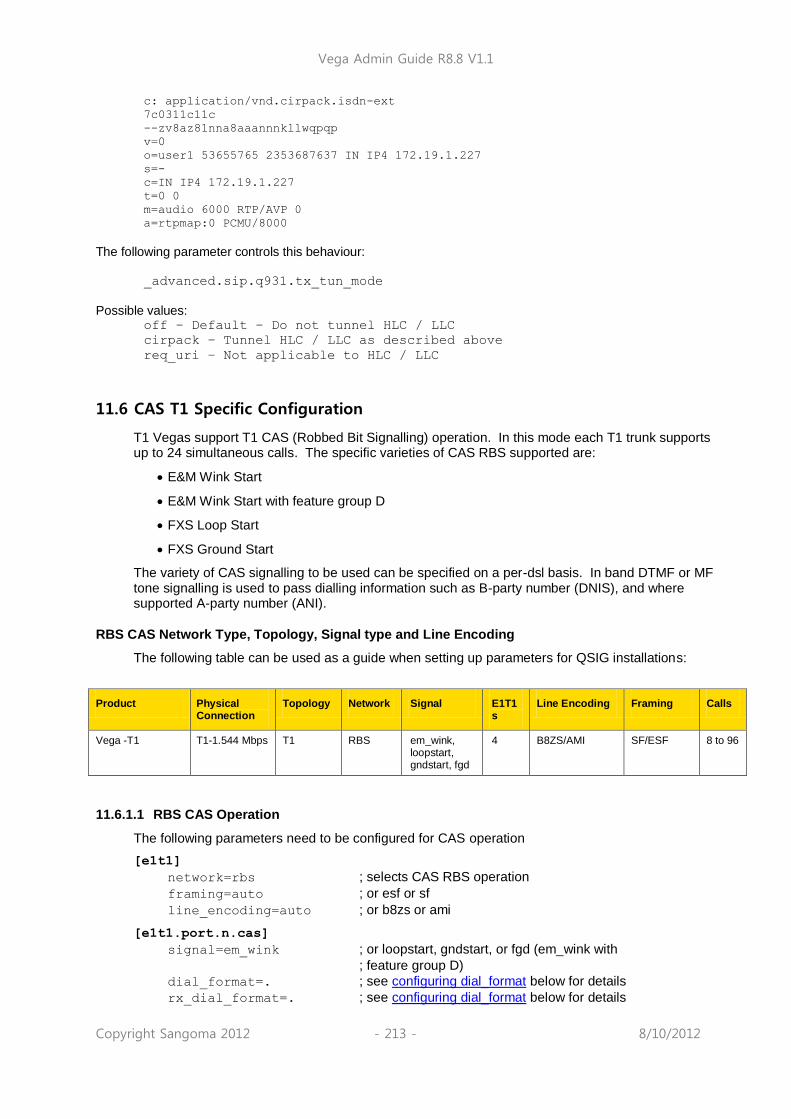
Vega Admin Guide R8.8 V1.1
Copyright Sangoma 2012 - 213 - 8/10/2012
c: application/vnd.cirpack.isdn-ext
7c0311c11c
--zv8az81nna8aaannnkllwqpqp
v=0
o=user1 53655765 2353687637 IN IP4 172.19.1.227
s=-
c=IN IP4 172.19.1.227
t=0 0
m=audio 6000 RTP/AVP 0
a=rtpmap:0 PCMU/8000
The following parameter controls this behaviour:
_advanced.sip.q931.tx_tun_mode
Possible values:
off – Default – Do not tunnel HLC / LLC
cirpack – Tunnel HLC / LLC as described above
req_uri – Not applicable to HLC / LLC
11.6 CAS T1 Specific Configuration
T1 Vegas support T1 CAS (Robbed Bit Signalling) operation. In this mode each T1 trunk supports up to 24 simultaneous calls. The specific varieties of CAS RBS supported are:
E&M Wink Start
E&M Wink Start with feature group D
FXS Loop Start
FXS Ground Start
The variety of CAS signalling to be used can be specified on a per-dsl basis. In band DTMF or MF tone signalling is used to pass dialling information such as B-party number (DNIS), and where supported A-party number (ANI).
RBS CAS Network Type, Topology, Signal type and Line Encoding
The following table can be used as a guide when setting up parameters for QSIG installations:
Product Physical Connection
Topology Network Signal E1T1s
Line Encoding Framing Calls
Vega -T1 T1-1.544 Mbps T1 RBS em_wink, loopstart, gndstart, fgd
4 B8ZS/AMI SF/ESF 8 to 96
11.6.1.1 RBS CAS Operation
The following parameters need to be configured for CAS operation
[e1t1]
network=rbs ; selects CAS RBS operation
framing=auto ; or esf or sf
line_encoding=auto ; or b8zs or ami
[e1t1.port.n.cas]
signal=em_wink ; or loopstart, gndstart, or fgd (em_wink with
; feature group D)
dial_format=. ; see configuring dial_format below for details
rx_dial_format=. ; see configuring dial_format below for details

Vega Admin Guide R8.8 V1.1
Copyright Sangoma 2012 - 214 - 8/10/2012
tx_dial_format=. ; see configuring dial_format below for details
digit_dial_timeout=6 ; Time after last dialled digit is received that DNIS / ANI
; are treated as complete – 1-1000 seconds info=dtmf ; DTMF or MF
tone_delay=50 ; delay after ack wink that first tone is sent, 1-1000 ms
[e1t1.port.1.group.m] first_chan=1
last_chan=auto ; Check that this is auto or 24
[e1t1.port.2.group.m] first_chan=1
last_chan=auto ; Check that this is auto or 24
1. Some CAS schemes (e.g. E&M wink start) do not have a
“called party alerting” message – call progress tones (ringing, busy etc.) are passed in the media channel. For the calling party to hear these, a media path must be established well before the connect is received – i.e. early media must be supported and used on the VoIP side, e.g. for the Vega either configure: a) early H.245, or b) fast start with accept_fast_start=3
2. For ground start and loop start signalling the Vega only supports the TE/Slave side of the signalling protocol.
Configuring dial_format
ANI and DNIS are presented as in-band tones (DTMF or MF tones), separated by specifed delimiter tones. The e1t1.port.x.cas.dial_format parameter, now superceeded by
e1t1.port.x.cas.rx_dial_format (for incoming calls) and
e1t1.port.x.cas.tx_dial_format (for outgoing calls) allows the format of the reception and
presentation of the ANI and DNIS to be specified.
o = ANI (Caller‟s telephone number)
n = DNIS (Called party number / Dialled number)
DTMF can use the separator characters: 0-9, A-D, *,#, ~
MF can use the separator characters: 0-9, K, S, ~
where ~ indicates no character expected, K = MF KP tone, and S = MF ST tone.
e.g. *o#*n# indicates the sequence *, ANI digits, #, *, DNIS digits, #
By default
[e1t1.port.x.cas]
dial_format=.
rx_dial_format=.
tx_dial_format=.
this configures the vega to automatically select an entry from the following table based on its signalling configuration:
NOTE

Vega Admin Guide R8.8 V1.1
Copyright Sangoma 2012 - 215 - 8/10/2012
DTMF MF
E&M wink, groundstart, loopstart
*n# KnS
Fgd (e&M winkstart with feature group D)
*o#*n# KoSKnS
The durations of the DTMF and MF signalling tones (and inter-tone silence)is specified by dtmf_cadence_on_time
and dtmf_cadence_off_time. You may wish to reduce
the default values of these parameters to around 70ms to 100ms each to speed up the signalling interchange.
NT/TE Configuration
E&M signalling, including feature group D is a symmetric signalling scheme, so there is no need for NT/TE configuration. With loopstart and ground start signalling, which are non-symmetric, the Vega only supports the TE side of the signalling, so again, the NT/TE is not configurable.
The value of the clock_master parameter does still need to be set up.and should be configured
as 1 if the device to which the vega is attached in not sourcing the clock, and should be set to 0 if
the other end is supplying the clock.
For E1T1 Vegas the pinout is changed internally depending on the Nt/TE setting, so in general a straight through cable can be used to connec to the far end device..
Further details of the Vega and cable pinouts may be found in the Product Details section of the www.wiki.sangoma.com/vega web site.
11.7 CAS E1 Specific Configuration
E1 CAS R2MFC
The only form of CAS signalling that the Vega gateways support is R2 MFC, a compelled tone based CAS signalling.
Details on how to configure the Vega for R2MFC signalling may be found in the Information Note “Configuring R2MFC” available from the www.wiki.sangoma.com/vega web site.
11.8 SIP Private Wire Configuration
Private wires are supported over SIP, private wires establish fixed, nailed up connections between endpoints. The mode of operation is that the Vega will attempt to establish 24 calls (for T1) or 30 calls (for E1) over SIP as soon as the E1T1 link becomes active.
In order to configure private wire, firstly the E1 or T1 network type must be set to “cas_pw”. Then the signalling scheme can be selected.
The following signalling schemes are supported:
NOTE

Vega Admin Guide R8.8 V1.1
Copyright Sangoma 2012 - 216 - 8/10/2012
pw_mrd
pw_pwa
pw_em
pw_plar pw_fxs
pw_fxo
pw_tos
All of the bit patterns for the signalling schemes are completely configurable.
12 POTS CONFIGURATION
Unlike digital systems which can be configured as either NeTwork side or Terminal Equipment side through software configuration, the hardware required to implement analogue interfaces is different depending on whether the gateway is to connect to telephones or whether the gateway is to connect as though it were a set of telephones. The two types of analogue interface are known as FXS (Subsciber / Phone facing – like lines from the PSTN or extension port interfaces on a PBX) and FXO (Office / Network facing – like a bank of telephones).
Therefore, with analogue gateways the type and number of analogue ports must be specified when ordering the product as it is not user configurable.
12.1 FXS Supplementary Services
A number of supplementary services are supported, these are:
Call Transfer
Three Way Call (3 Party Conference)
Call Forward
Do Not Disturb (DND)
Call Waiting
Call Transfer
See IN27 – FXS Call Transfer, available on www.wiki.sangoma.com/vega for details on this feature.

Vega Admin Guide R8.8 V1.1
Copyright Sangoma 2012 - 217 - 8/10/2012
Three Way Calling
When two calls are connected to an FXS port it is now possible to configure the gateway to allow for the three calls to be connected (conference call). This feature is only available for SIP firmware builds.
Depending on the configuration, the three-way call can be initiated by the FXS user using „command mode‟ (a sequence of digits are dialled to initiate the three-way connection) or using „simple mode‟ (a number of „hook-flashes‟ are performed to initiate the three-way connection).
The three way call can be initiated using two different call flow scenarios:
Call Transfer
Call Waiting
Sample Network Diagram
LAN
FXS
SIP PHONESIP PHONE
A C
B
12.1.1.1 Command Mode / Call Transfer Three Way Call
A (SIP Phone) calls B (Analogue Phone connected to FXS port)
A connects to B
B performs a hookflash, dials C (SIP Phone)
B connects to C
B can perform further hookflashes to toggle between A and C
B enters command mode string (by default this is *54)
A, B & C enter Three Way Call
12.1.1.2 Command Mode / Call Waiting Three Way Call
A (SIP Phone) calls B (Analogue Phone connected to FXS port)
A connects to B
C calls B (B hears Call Waiting „beep‟)
B performs a hookflash and connects to C
B can perform further hookflashes to toggle between A and C
B enters command mode string (by default this is *54)
A, B & C enter Three Way Call

Vega Admin Guide R8.8 V1.1
Copyright Sangoma 2012 - 218 - 8/10/2012
12.1.1.3 Simple Mode / Call Transfer Three Way Call
A (SIP Phone) calls B (Analogue Phone connected to FXS port)
A connects to B
B performs a hookflash, dials C (SIP Phone)
B connects to C
B performs a further hookflash
A, B & C enter Three Way Call
In Simple Mode the following number of hookflashes result in the following call connections:
First hookflash = talk to 1st caller
Second hookflash = talk to 2nd caller
Third hookflash = conference
Fourth hookflash as first hookflash
12.1.1.4 Simple Mode / Call Waiting Three Way Call
Call Waiting Three Way Call initiation is not supported when the Conference mode is „Simple‟.
12.1.1.5 Three Way Call Indications
When switching to talk to the 1st caller the FXS user should hear a single short beep just before
being connected.
When switching to talk to the 2nd
caller the FXS user should hear two short beeps just before being connected.
When switching to talk in conference mode the FXS user should hear a single long beep just before being connected.
12.1.1.6 Configuration
All Supplementary Service configuration can be performed via the Web User Interface (WUI). The following parameters are accessible via the Command Line Interface (CLI).
Overall activation of Supplementary Services is enabled using the following parameter:
suppserv.enable
Where the parameter value can be :
0 = Disable supplementary services.
1 = Enable supplementary services (default setting).
The call conference mode is defined by the following parameter:
suppserv.profile.1.call_conference_mode
Where the parameter value can be:
cmd_mode = Use command mode (dialled digit command) to initiate conference call.
simple = Use „simple mode‟ (hookflashes) to initiate conference call.
The call conference command is defined by the following parameter:

Vega Admin Guide R8.8 V1.1
Copyright Sangoma 2012 - 219 - 8/10/2012
suppserv.profile.1.code_call_conference
Where the parameter value can be:
A string of between 1 and 9 characters (these characters must be „diallable‟ digits).
The default string is *54

Vega Admin Guide R8.8 V1.1
Copyright Sangoma 2012 - 220 - 8/10/2012
Call Forwarding
Call forwarding can optionally be enabled for FXS ports. Three variants are available:
Call Forward No-Answer (CFNA)
Call Forward Busy (CFB)
Call Forward Unconditional (CFU)
Call forwarding can be programmed using the handset or via CLI commands. Optionally call forwarding statuses can be saved and restored to a server.
When a call is forwarded the dial plans are used in order to try to route the call.
When call forwarding is enabled, when going off-hook, the POTS user will hear 3 short dial tone bursts, followed by a short pause, followed by the normal dial tone (or stutter dial tone).
12.1.1.7 Operation Examples
(Assuming default configuration, as below)
To set Call Forward Always with destination 555:
1. lift handset on POTS port
2. dial *72 555 #
This means that all calls for POTS port 1 will get forwarded to tel number 555.
To disable Call Forward Always:
1. lift handset on POTS port
2. dial *73
To enable Call Forward Always without altering call forward destination
1. lift handset on POTS port
2. dial *72 #
N.B. Call forward destinations are the same for all call forwarding.
i.e. you can't have different call forward destinations for different types of call forwarding.
12.1.1.8 Parameters
Configuring DTMF codes for call forward enable / disable:
suppserv.profile.1.code_cfb_on Default *90
suppserv.profile.1.code_cfb_off Default *91
suppserv.profile.1.code_cfna_on Default *92
suppserv.profile.1.code_cfna_off Default *93

Vega Admin Guide R8.8 V1.1
Copyright Sangoma 2012 - 221 - 8/10/2012
suppserv.profile.1.code_cfu_on Default *72
suppserv.profile.1.code_cfu_off Default *73
suppserv.profile.1.code_disable_all Default *00
(for all of these, default is as above but will allow any 9 character string)
12.1.1.9 Enabling call forward:
Parameter added:
pots.port.x.call_fwd_enable
Possible values:
on – Default – Allow specified port to activate call fwd
off – Do not allow call forward on specified port
Parameter added:
_advanced.pots.save_pots_user_status
Possible values:
off - Default – Do not save status to server
ftp – Save status to FTP server
12.1.1.10 CLI Commands - Call Forwarding Control
fxs cf dest - USAGE: fxs cf dest <port> <call fwd dest or NULL>
fxs cfu - USAGE: fxs cfu <port> <on/off>
fxs cfb - USAGE: fxs cfb <port> <on/off>
fxs cfna - USAGE: fxs cfna <port> <on/off>
Examples:
admin >fxs cf dest 1 555
port 1, set call forward destination to 555
admin >fxs cfu 1 on
port 1, enabled call forward unconditional
admin >fxs cfu 1 off
port 1, disabled call forward unconditional
admin >fxs cf dest 1 NULL
port 1, clear call forward destination

Vega Admin Guide R8.8 V1.1
Copyright Sangoma 2012 - 222 - 8/10/2012
12.1.1.11 CLI Commands - Call Forward Status Using "show ports”
To query call forward status:
admin >show ports
Physical ports:
Name Type Status
---------- ----- -------------------------
POTS-1 POTS (FXS) on-hook ready (cfu,dest=555)
POTS-2 POTS (FXS) on-hook ready
This shows that a call forward unconditional has been set with destination 555.
12.1.1.12 Call Forward Status - Preservation After Reboot
Config Variable:
_advanced.pots.save_pots_user_status=off or ftp
default is "off"
If set to "ftp", then "call forward" and "do not disturb" status will be attempted to be stored to the configured FTP server.
Then on a reboot, the file will be read from the FTP server.
The filename will take the format XXXXXXXXXXXXfxsstatY.txt
where:
XXXXXXXXXXXX is the 12 character serial number of the unit
Y is a number representing the FXS port number
For example: 005058020604fxsstat2.txt
_advanced.pots.save_pots_user_status=off or ftp
default is "off"
If set to "ftp", then "call forward" and "do not disturb" status will be attempted to be stored to the configured FTP server.

Vega Admin Guide R8.8 V1.1
Copyright Sangoma 2012 - 223 - 8/10/2012
Do Not Disturb (DND)
Do Not Disturb (DND) can optionally be enabled for FXS ports. DND can be programmed using the handset or via CLI commands. Optionally DND statuses can be saved and restored to a server.
When DND is enabled, when going off-hook, the POTS user will hear 3 short dial tone bursts, followed by a short pause, followed by the normal dial tone (or stutter dial tone).
The Vega can be configured to either send a busy message or ringing indication back to the calling party.
12.1.1.13 Operation Examples
(Assuming default configuration, as below)
To activate DND:
1. Lift handset on POTS port 2. Dial *78
This means that all calls for POTS port 1 will be rejected with behaviour set by the DND parameters.
To disable DND:
1. Lift handset on POTS port 2. Dial *79
12.1.1.14 Configuration Parameters
suppserv.profile.x.code_dnd_on Default *78
suppserv.profile.x.code_dnd_off Default *79
(for all of these, default is as above but will allow any 9 character string)
Parameter:
pots.port.x.dnd_enable
Possible Values:
on – Default – Allow DND to be activated for specified port
off – DND cannot be activated for specified port
Parameter:
pots.port.x.dnd_off_hook_deactivate
Possible Values:
on – Going off-hook immediately cancels DND
off – Default – Going off-hook does not cancel DND
Parameter:
pots.port.x.dnd_response
Possible Values:
instant_reject – Default - Instant_reject call with SIP 480 or SIP
message as defined by do_not_disturb.status_code

Vega Admin Guide R8.8 V1.1
Copyright Sangoma 2012 - 224 - 8/10/2012
spoof_ringing – Send ringing back to call originator
Parameter:
_advanced.sip.do_not_disturb.status_code
Possible Values:
400-699 - Default 480 – SIP status code to use for DND
Parameter:
_advanced.sip.do_not_disturb.status_text
Possible Values:
String up to 47 characters, default "Do Not Disturb"
12.1.1.15 CLI Commands - DND Control
fxs dnd - USAGE: fxs dnd <port> <on/off>
Example:
admin >fxs dnd 1
port 1, enabled do not disturb
12.1.1.16 CLI Commands - DND Status Using "show ports”
To query DND status:
admin >show ports
Physical ports:
Name Type Status
---------- ----- -------------------------
POTS-1 POTS (FXS) on-hook ready (dnd)
If DND has been activated, the "(dnd)" text will be present
12.1.1.17 DND Status - Preservation After Reboot
See entry under “Call Forward” for details.
Call Waiting
When a call is placed into an FXS port that already has an active call the Vega (if configured) plays a call waiting indication tone to the FXS port and sends a SIP 180 or 183 message to the new caller to indicate ringing. Optionally the Vega can now be configured to send a SIP 182 – Queued – message so that the caller is aware of the status of the call.
Parameter: _advanced.sip.call_waiting.status_code
Possible values: off – Default – Use SIP 180 / 183 as normal
182 – Use SIP 182 Queued for call waiting call
See “IN38 – FXS Call Waiting” for more information on this feature.

Vega Admin Guide R8.8 V1.1
Copyright Sangoma 2012 - 225 - 8/10/2012
12.2 POTS Phone Facing (FXS) ports
FXS ports on a Vega gateways are designed to connect to conventional, loop start POTS telephony products such as telephones and faxes; also to connect to analogue trunk interfaces of PBXs. Operation of the interface involves the following activities:
DTMF digit detection
DTMF Digits are detected automatically by the Vega and no parameters are necessary to configure this operation.
Hook Flash detection
The maximum period of time for detecting a line break as a hookflash (as opposed to on-hook) is configured in
[_advanced.pots.fxs.x]
hookflash_time
Typically, values of between 100ms and 800ms are appropriate.
If the call clears when hookflash is being detected, then increase the value of hookflash_time.
Also see:
[_advanced.pots.fxs.x]
hookflash_debounce_time
Ring Cadence Generation
Each POTS port can generate a number of different (or distinctive) outgoing ring patterns. A
different ring pattern can be referenced (ring_index) for each different “group” section created
for the FXS POTS port concerned. The ring cadence generator uses the ring_index to select a
particular ring pattern as defined in _advanced.pots.ring.x.
E.g. The following parameters would be used to configure the Vega such that whenever an outgoing call is presented to FXS interface 33 the ring pattern is defined by the first entry in the ring cadence table:
[pots.port.n.if.m]
ring_index=1
interface=33
[_advanced.pots.ring.1]
frequency=50
name=Internal-UK
… etc.
Line supervision – Answer and disconnect
Loop Current disconnect
FXS ports on Vega gateways can be configured to provide a Loop Current Disconnect signal on their FXS ports when calls cleardown on the LAN side. To configure Loop Current Disconnect generation on FXS ports, use the following parameters:
[_advanced.pots.fxs.1]
loop_current_break
loop_current_delay
loop_current_time
loop_current_break is the overall enable / disable flag, loop_current_time is the time that
the loop current will be broken for (make sure that this is slightly longer than the attached devices‟ detection period). loop_current_delay is a configurable delay after the other party has

Vega Admin Guide R8.8 V1.1
Copyright Sangoma 2012 - 226 - 8/10/2012
cleared that the Vega waits before issuing the loop current disconnect; this gves the FXS party a chance to clear the call before the loop current disconnect is issued.
Whilst the loop current disconnect is being issued, there is no line voltage / current to detect, and so no other POTS events can be detected, for example, on-hook and off-hook events can not be detected until completion of the loop current disconnect.
Line Current Reversal
FXS ports may be configured to reverse the line voltage on the POTS interface on call answer and call disconnect. To enable this function set:
[_advanced.pots.fxs.x]
line_reversal=1
WARNING!
If the Vega is configured to operate using line current reversal then the device which is attached to the Vega must also support this functionality as answer and cleardown are indicated using the line current reversals.
DTMF digits after answer
Vega FXS ports can be configured to send DTMF digits after answer in order to further route the call on the connected device. This feature is controlled by the TEL: token in the destination dial plan entry; if a dial plan entry that routes calls to an FXS port has a TEL: token containing some digits, when the FXS port is taken off-hook the DTMF will be played out. e.g.. if the following dial plan routes the call:
srce=IF:99..,TEL:<501> dest=IF:0101,TEL:<1>
the Vega will play out the digits 501 immediately after the call is answered on port FXS 1.
12.3 POTS Network Facing (FXO) ports
FXO ports on Vega gateways are designed to connect to an analogue CO switch or analogue extension ports on a PBX.
Line voltage detection
Before an outbound call is made Vega FXO ports check that there is line voltage on the line. If no line voltage is observed (less than +/- 5volts) the call is rejected with cause code 27; this can be checked for in the dial planner / call presentation group and used to represent the call to another destination which is active.
Impedance configuration
The impedance of the FXO ports is configurable from the user interface (both web browser and CLI). Three choices of impedance are selectable:
NOTE

Vega Admin Guide R8.8 V1.1
Copyright Sangoma 2012 - 227 - 8/10/2012
1. 600R (US style) 2. CTR21 (European style) 3. 900R
Although in practice the Vega will operate when the impedance is set incorrectly, for approvals reasons it is important that you configure the FXO port to the impedance utilised by the country in which the Vega is installed. For example:
600R CTR21
Canada, Caribbean, Central America, China, Hong
Kong, Malaysia, Mexico, Saudi Arabia, South America, Taiwan, Thailand, United Arab
Emirates, United States
Austria, Belgium, Cyprus, Denmark, Finland, France, Germany, Greece, Iceland,
Ireland, Israel, Italy, Liechtenstein, Luxembourg,
Netherlands, Norway, Portugal, Spain, Sweden,
Switzerland, United Kingdom
FXO port impedance is configured in the FXO Port Hardware Configuration Profile parameters:
[_advanced.pots.fxo.y]
impedance
On the web browser, change it in the FXO Parameters section of the POTS > Advanced POTS > FXO Configuration > Hardware Profile Configuration (Modify) Ensure that the hardware profile associated with the port has the correct impedance set. The hardware profile selection for each FXO port is made in:
[pots.port.x]
fx_profile
Set fx_profile=y
On the web browser, this is found it in the Modify Port section of the POTS > Port Configuration
(Modify)
DTMF digit generation
The DTMF on/off times, initial holdoff between off-hook and dialling, and DTMF tone amplitude are all user configurable:
[_advanced.pots.fxo.x]
dtmf_holdoff_time=200
[_advanced.dsp]
dtmf_gain=10000 - being superceeded by dtmf hi / lo gain
dtmf_hi_gain
dtmf_lo_gain
dtmf_cadence_on_time=150
dtmf_cadence_off_time=250
It is strongly recommended that the values of dtmf_hi_gain and dtmf_lo_gain are not
altered; changing these value from default may cause the Vega to produce out-of-spec DTMF tones
NOTE

Vega Admin Guide R8.8 V1.1
Copyright Sangoma 2012 - 228 - 8/10/2012
Hook Flash generation
The time period for generating the hookflash (on-hook) pulse is configured in
[_advanced.pots.fxo.x]
hookflash_time
Typically a value of around 500ms is appropriate.
Ring Cadence Detection
FXO ports on a Vega gateway are only capable of detecting a single incoming ring pattern. The following parameters are used to configure the cadence detection circuit for a particular ring:
[_advanced.pots.fxo.x]
ring_detect_longest_ring_off=5000
ring_detect_shortest_ring_on=250
Examples:
Parameter UK USA
Longest silence 2000ms 4000ms
Shortest ring 400ms 2000ms
Line Supervision – Answer and Disconnect
Vega FXO ports operate in one of three modes for line supervision.
1) No Supervision Disconnect Supervision: In this mode the Vega FXO port is unaware of the on-hook/off-hook state of the far end during a call. The responsibility for tearing down a call lies with the VoIP side of the call, regardless of which end established the call. Usually the VoIP subscriber will hear the other party hang up followed by call progress tones indicating that the far end caller has disconnected; they will then hang up the call in response. Answer Supervision: When an outgoing call is attempted over the FXO interface the
Vega will connect and answer the incoming VoIP call at the same time as dialling out on the POTS line. If billing is carried out based on the VoIP messaging, callers will be charged for outdialling and any following success or failure messages – there is no answer signal available to be passed through the Vega.
2) Loop Current Detection: Disconnect Supervision: In this mode the Vega FXO port detects the short break in loop
current which the PBX / CO switch generates (to indicate that the far end party has terminated the call) and it will clear the call through itself. Answer Supervision: This method does not indicate that the far end has answered the call. When an outgoing call is attempted over an FXO interface the Vega will connect and answer the incoming VoIP call at the same time as dialing out on the POTS line. If billing is carried out based on the VoIP messaging, callers will be charged for outdialling and any following success or failure messages – there is no answer signal available to be passed through the Vega. Loop Current disconnect detection is enabled by setting:
[_advanced.pots.fxo.x]
loop_current_detect=loop_current_disconnect_time
The loop_current_disconnect_time value should be configured to be slightly
shorter than the period for which the PBX / switch makes the break in loop current.
The loop_current_detect time MUST be greater
than hook_flash_time, otherwise a hook flash will
cause the call to clear down.
NOTE

Vega Admin Guide R8.8 V1.1
Copyright Sangoma 2012 - 229 - 8/10/2012
3) Line Reversal Detection: Disconnect and Answer Supervision: In this mode the FXO port detects the polarity of
the line to determine if the far end has answered the call and also uses it to sense if the far end has terminated the call. When an outgoing call is attempted over the FXO interface the Vega will only connect the incoming VoIP side if the far end answers (indicated by the line current being reversed to its „active‟ state).
Call cleardown is indicated by the line current being reversed back to its „idle‟ state. If line reversal is supported by the CO Switch/PBX then it allows the Vega to answer the call when the destination call is answered and the Vega to clear the call when the destination call is cleared. If billing is being carried out on the VoIP messaging then the caller will correctly only be billed for the voice connected part of the call. It is enabled by setting:
[_advanced.pots.fxo.x]
line_reversal_detect =1
Other parameters associated with line current reversal are:
[_advanced.pots.fxo.x]
line_reversal_sample_delay=<time>
line_reversal_debounce_time=<debounce time>
WARNING!
If line_reversal is enabled on a Vega FXO port but is not supported by the PBX / switch that it is connected to, then outgoing FXO calls will never be answered (as there will never be a line reversal)
If possible either loop current detection or line reversal should be used to ensure calls are cleared from FXO ports in a timely manner. However only one method of supervision should be enabled at a time – enabling them both is likely to stop the Vega handling calls correctly.
Tone Detection
If no other means of reliable disconnection signalling are available (i.e. battery line reversal or loop current disconnection signalling) and progress tones are provided (i.e. busy, congestion and disconnection indications) a Vega gateway can be configured to detect disconnection tones which are received on an FXO port. It is useful to think of an FXO interface / port as an analogue handset when considering call supervision. For an inbound call, as ringing voltage is received into an FXO interface, the port will go 'off-hook'. Depending on the dial plan configuration the inbound call maybe routed immediately to a destination interface or secondary dial tone may be played to the calling party (who is making the calling 'into' the FXO port). For an outbound call, as a call is routed (via the dial plan) to the FXO interface, the port goes 'off-hook' and plays DTMF tones to the exchange / pbx (i.e. the called number is dialled). At this point of the call the calling leg of the call will automatically be connected, i.e. if the calling party is SIP a 200 OK is sent immediately to the calling party. Once the inbound (or outbound) call is terminated by the PSTN / PBX party (or the call fails to establish as the destination is busy or congested), disconnection tones are played towards the FXO interface. If configured to do so, the FXO interface will detect these tones and the FXO port will go 'on-hook' ready for another call.

Vega Admin Guide R8.8 V1.1
Copyright Sangoma 2012 - 230 - 8/10/2012
12.3.1.1 Configuration
Firstly, if tone detection is going to be used as the method for call disconnection ensure that all other disconnection methods are disabled. The following parameters values disable all other disconnection methods: _advanced.pots.fxo.1.line_reversal_detect=0
_advanced.pots.fxo.1.loop_current_detect=0
_advanced.pots.fxo.1.voice_detect=0
The following parameters determine the FXO interface tone disconnection configuration (and activation): _advanced.pots.fxo.x.tone_detect
Where 'x' represents the FXO profile in use by a specific port. Possible values are: 0 (default) - disconnection tone detection is disabled. 1 - disconnection tone detection is enabled. Busy, Congestion and Disconnection tones can (each optionally) be detected by configuring the following parameter set values: tonedetect.x.y.enable
tonedetect.x.y.freq1
tonedetect.x.y.freq2
tonedetect.x.y.freq3
tonedetect.x.y.off_time1
tonedetect.x.y.off_time2
tonedetect.x.y.off_time3
tonedetect.x.y.on_time1
tonedetect.x.y.on_time2
tonedetect.x.y.on_time3
Where: x = busy, congestion or disconnect y = profile index - i.e. if two different busy tones need to be detected a profile can be created for each type of tone detection, i.e. tonedetect.busy.1 and tonedetect.busy.2 etc. In the majority of cases only one profile needs to be configured for each disconnection tone type (busy, congestion, disconnection). tonedetect.x.y.enable
Possible values are 0 or 1 - i.e. disable or enable the detection of the tone defined in this tone detection profile. tonedetect.x.y.freq1
tonedetect.x.y.freq2
tonedetect.x.y.freq3
Possible values are 250 - 700, which represents a frequency (in Hz) present in the tone defined in this tone detection profile. If the tone is single frequency the values of freq2 and freq3 should be set to 0 - i.e. no detection. tonedetect.x.y.off_time1
tonedetect.x.y.off_time2
tonedetect.x.y.off_time3
Possible values are 0 to 10,000, which represents the off time (in Miliseconds) of the cadence of the tone to be detected. Tones which contain mutliple cadences can be detected by configuring differing off_time values (i.e. off_time2 and off_time3). Unless the tone does contain multiple cadences off_time2 and off_time3 should be set to 0 - i.e. no multi-cadence detection. tonedetect.x.y.on_time1
tonedetect.x.y.on_time2
tonedetect.x.y.on_time3
Possible values are 100 to 10,000, which represents the on time (in Miliseconds) of the cadence of the tone to be detected. Tones which contain mutliple cadences can be detected by configuring differing on_time values (i.e. on_time2 and on_time3). Unless the tone does contain multiple cadences off_time2 and off_time3 should be set

Vega Admin Guide R8.8 V1.1
Copyright Sangoma 2012 - 231 - 8/10/2012
to 0 - i.e. no multi-cadence detection.
12.3.1.2 Detecting Tones
There are a number of commands that can be used to display the tones that are received at the Vega FXO port. The output of these commands can be used to correctly configure the parameters described above.
To display the frequencies and cadences that are being received the following commands can be
issued: debug on debug tone enable
When the debug tone enable command is issued the Vega is no longer able to detect tones
and thus disconnect calls. i.e. It‟s not possible to both debug and detect tones.
See below for sample output from the above commands.
To stop the debug output: debug tone disable
To query the status of the commands: debug tone status
Sample Output
_DSP :Trace : 0145465: 07315:DSP :user-defined tone detected digit 412Hz,0Hz (digit 3)
:(dspac.c;1036)
_DSP :Trace : 0145835: 00370:DSP :user-defined tone is now off :(dspac.c;914)
_DSP :Trace : 0146215: 00380:DSP :user-defined tone detected digit 412Hz,0Hz (digit 3)
:(dspac.c;1036)
_DSP :Trace : 0146595: 00380:DSP :user-defined tone is now off :(dspac.c;914)
_DSP :Trace : 0146970: 00375:DSP :user-defined tone detected digit 412Hz,0Hz (digit 3)
:(dspac.c;1036)
_DSP :Trace : 0147350: 00380:DSP :user-defined tone is now off :(dspac.c;914)
_DSP :Trace : 0147730: 00380:DSP :user-defined tone detected digit 412Hz,0Hz (digit 3)
:(dspac.c;1036)
_DSP :Trace : 0148110: 00380:DSP :user-defined tone is now off :(dspac.c;914)
From the sample output above it can be seen that the detected frequency was 412Hz and the cadence is 370ms on-time (145835 – 145465) and 380ms off-time(146215 – 145835)
FXO – Slow network cleardown
In certain networks, for instanceMobile networks it takes a long time for the Network to clear. If a new call is made immediately after a previous one clears, the call will fail. In order to accommodate this, the Vega can be configured to prevent new calls to FXO ports until a specified period has passed since the previous call cleared. To configure this, use parameters:
[_advanced.pots.fxo.x]
port_notreleased_cause
port_release_delay
If a call is attempted within the port_release_delay period after the previous call cleared, then the Vega will reject the call with cause code port_notreleased_cause. This can be used to try and re-present the call using call re-presentation.
FXO – Secondary dial tone
Usually an FXO interface will immediately route a call as soon as it detects ring tone.
If the dial plan specifies a TEL: token in the dial plan for an FXO port, when a call arrives at that port, rather than routing the call immediately, dial tone will be played to the caller. The caller can

Vega Admin Guide R8.8 V1.1
Copyright Sangoma 2012 - 232 - 8/10/2012
then enter digits using DTMF tones (phone key presses), and the digits received will provide digits for the TEL: token comparison in the dial planner. Calls can now be routed using TEL:, as well as TELC:, IF: etc.
The time that dial tone is played for (and before the call is routed assuming NO digits are entered) is defined by:
[pots.profile.2]
dtmf_dial_timeout=5
(this is the inter digit DTMF timeout). If the timeout is set to 0 then the call will be routed immediately (effectively turning off the secondary dial tone feature).
12.4 Analogue Caller-ID (CLID)
Analogue Vega gateways support caller ID by receiving / generating FSK or DTMF tones during the ringing phase of a call.
Vega FXS ports generate the tones towards the attached telephones, and FXO ports detect the tones when they are sent by the attached PBX / CO switch.
Several types of CLID encoding are supported on the Vega units; the appropriate mechanism can be configured by setting the parameter:
[pots.profile.1.] callerid_type=gr30-sdmf / gr30-mdmf / bt / etsi-fsk / etsi-fsk-lr
/ etsi-fsk-post / etsi-dtmf / etsi-dtmf-lr / etsi-dtmf-post / off
gr30-sdmf Conforms to Bellcore standard GR30 - single data message format. Just passes the call time and number information. The latest standard mentions that this format may be dropped in future. gr30-mdmf Conforms to Bellcore standard GR30 - multiple data message format. This passes the caller name as well as the call time and number. (This configuration will also receive gr30-sdmf caller Ids) bt Based on the gr30-mdmf format but with a difference in the tones and interface to the POTS as required for use in the UK. The specification requires the phone to send a whetting pulse after the first tones are detected. etsi-fsk
Use ETSI FSK, delivered before ring. etsi-fsk-lr Use ETSI FSK, delivered before ring but after line reverse. etsi-fsk-post
Use ETSI FSK, delivered between 1st and 2
nd ring.
etsi-dtmf Use DTMF, delivered before ring. etsi-dtmf-lr
Use DTMF, delivered before ring but after line reverse. etsi-dtmf-post Use DTMF, delivered between 1
st and 2
nd ring.
off
Turns off Caller ID handling.

Vega Admin Guide R8.8 V1.1
Copyright Sangoma 2012 - 233 - 8/10/2012
The parameter
[pots.port.n]
callerid
controls Caller ID on a port by port basis; it can take the values off or on.
FXS – Outbound Analogue Caller ID (CLID) – H.323 and SIP
Caller ID generation can be enabled and disabled on a per port basis using
[pots.port.n]
callerid=on/off.
The particular line encoding type used must be set up in:
[pots]
callerid_type= caller Id type
Caller ID is sent out both at the start of a call and, if the call waiting supplementary service is enabled, when a 2
nd call arrives mid call
FXO – Analogue Caller ID detection (CLID) – H.323 and SIP
Incoming caller id is configured using 3 parameters,
[pots.port.n]
callerid = on/off
[pots]
callerid_type = caller id type
callerid_wait = time to wait to see if a callerID is being
presented – if time is exceeded then the Vega
assumes that no caller ID will be received.
Vega FXO ports do not support the generation of caller ID.
Some caller ID generation methods provide no warning that caller ID is about to be delivered. i.e. there is no initial ring splash or line whetting pulse. For these installations the Vega can now allocate a DSP resource to permanently listen for caller ID tones.
The Vega will only allocate a permanent DSP resource where there is line voltage present on the FXO port (i.e. there is a connected device) and the configured caller ID type doesn‟t provide any warning of caller ID delivery. i.e. One of the following types of caller ID is configured:
etsi-fsk
etsi-dtmf
WARNING!
This permanent allocation may affect the ability of other ports on the gateway to complete calls. This affects gateways where there are both FXS and FXO ports.
12.4.1.1 SIP Presentation Field
This presentation field address extension may be present in the From: header of an INVITE as:
”presentation =” ( “anonymous” | “public” | “unavailable”)

Vega Admin Guide R8.8 V1.1
Copyright Sangoma 2012 - 234 - 8/10/2012
If caller ID is on, the caller ID will be displayed (passed on) if:
There is NO presentation address extension in the From: header of the INVITE message
The INVITE message‟s presentation is “public”
Caller ID WILL NOT BE DISPLAYED (will not be passed on) if:
The INVITE message‟s presentation is “unavailable”, in which case the phone will display “OUT OF AREA”
The INVITE message‟s presentation is “anonymous”, in which case the phone will display “BLOCKED CALL”
If there is no caller ID to put in the From: field (none supplied, presentation restricted etc.) then “Unknown” will be used.
See also RPID handling in section 0 RPID – Remote Party ID header.
12.4.1.2 H.323 extensions
Additional parameters are available to configure the text of the messages that are sent over H.323 under specific received caller ID situations:
[advanced.h323control]
nocallerid=<no caller id text>
notavail=<no caller id available text>
restricted=<caller id is restricted text>
12.5 Power fail fallback operation
Vega FXS gateways which include 2 FXO ports support power fail fallback. If the Vega is powered down, rebooted, or in the middle of an upgrade, it will use fall back relays to connect the first two FXS ports to the two FXO ports. This provides emergency telephony, even under VoIP-down conditions.
On returning to an active state, the Vega samples the condition of the FXS < -- > FXO lines, if either are in use, it will delay removing the relay connection until both are free.
12.6 Pulse Dialling
Pulse dialling generation is supported on FXO ports and pulse dial detection is supported on FXS ports.
Configuration Parameters
The following configuration parameters control this feature:
Parameter Name Default Range Description _advanced.pots.fxs
pulse_dial_detection 1 (enabled) 0..1 enables the feature for detection pulse dialed digits at the FXS interface
min_pulse_break_time 50 25..100 (mS) adjustment for decoding pulse break period
max_pulse_break_time 70 25..100 (mS) adjustment for decoding pulse break

Vega Admin Guide R8.8 V1.1
Copyright Sangoma 2012 - 235 - 8/10/2012
period
min_pulse_make_time 30 20..60 (mS) adjustment for decoding pulse make period
max_pulse_make_time 50 20..60 (mS) adjustment for decoding pulse make period
min_pulse_interdigit_time 300 100..3000 (mS) adjustment for decoding pulse interdigit period
pulse_dial_encoding normal normal, Sweden new_zealand
Selection of encoding scheme for digit pulses
_advanced.pots.fxo
pulse_dial_enable never (disabled)
never, dialing_only, always
Selects support for outpulsing digits at FXO interface
pulse_break_time 60 25..100(mS) adjustment for output pulse break period (mS)
pulse_make_time 40 20..60 (mS) adjustment for output pulse make period (mS)
pulse_interdigit_time 300 100..3000 (mS) adjustment for output pulse interdigit period (mS)
pulse_dial_encoding normal normal, Sweden, new_zealand
Selection of encoding scheme for digit pulses
Recommended settings for parameters
_advanced.pots.poll_timer=5
The default for this parameter is 15mS. The feature will not work optimally at this value: incoming digits will not be decoded correctly. 10mS may be ok but best performance is at 5mS. We need to do some performance comparisons at both settings to determine optimum setting.
_advanced.pots.fxs. hookflash_debounce_time=80
To avoid spurious hookflash events being triggered by pulse dialed digits at the FXS interface, the hookflash_debounce_time should be set to a value greater than the pulse break time i.e. max_pulse_break_time. The max_pulse_break_time default value is 70mS; therefore the hookflash_debounce_time should typically be set to a minimum of 80mS.
Note: there is a warning reported if misconfigured.
_advanced.pots.fxs. wink_debounce_time=80
Similarly, to avoid spurious wink events being triggered by pulse dialed digits at the FXS interface, the wink_debounce_time should be set to a value greater than the pulse break time i.e. max_pulse_break_time. The wink_debounce_time should typically be set to a minimum of 80mS.
Note: there is a warning reported if misconfigured.

Vega Admin Guide R8.8 V1.1
Copyright Sangoma 2012 - 236 - 8/10/2012
13 H.323 CONFIGURATION
H.323 variants of the Vega gateway are designed to operate in one of two modes:
Gatekeeper mode
Standalone mode (no gatekeeper)
In Gatekeeper mode, at power up or re-boot the Vega will register with the gatekeeper, and then for each call the Vega will send the call details (like called number, calling number, name and if appropriate TA: and TAC:) to the gatekeeper and the gatekeeper will carry out the authentication, routing and translation, providing the Vega with destination dialled number, name and if appropriate TA: information.
In standalone mode, the Vega dial planner effectively implements a subset of gatekeeper functionality, carrying out the authentication, routing and translation internally.
Therefore, when a gatekeeper is used, the dial planner is typically much simpler than for standalone mode as the gatekeeper will do the number translations etc.
To select the mode of operation configure h323.gatekeeper.enable on the CLI or select the
appropriate “Gatekeeper Mode” or “Standalone” button on the H.323 page on the web browser interface.
Dial Planner
Gatekeeper
Whitelist
Standalone mode
Incoming Telephony Call
Outbound VoIP Call
Whitelist
Dial Planner
Gatekeeper
Standalone mode
Incoming VoIP Call
Outbound Telephony
Call
Incoming VoIP Call

Vega Admin Guide R8.8 V1.1
Copyright Sangoma 2012 - 237 - 8/10/2012
13.1 Standalone Mode
In standalone mode (h323.gatekeeper.enable=0) the Vega dial planner needs to be
configured to contain all operations for authentication, routing and translation.
Details on configuring the dial planner can be found in section 9 “The Dial Planner”.
In some cases it is required that most calls are to be routed to the same destination on the LAN (e.g. another gateway); to do this, a default H.323 endpoint address can be set up. This endpoint address is used in all cases where an explicit ongoing IP address is not specified in the dial plan entry.
[h323.if.x]
default_ip=www.xxx.yyy.zzz
default_port=1720
For readability, it is recommended that the TA: token is used explicitly in all dial plan entries rather than using the
default_ip parameter
13.2 Gatekeeper Mode
In gatekeeper mode (h323.gatekeeper.enable=1) a number of parameters need to be set up
to allow registration and authentication to take place with the gatekeeper. Specifying which gatekeeper to use is carried out by either specifying a static IP address/host name, or by enabling auto-discovery. In the latter case a multicast is used to find the nearest gatekeeper.
To enable auto-discovery set:
[h323.gatekeeper]
auto_discover=1
For manual discovery a gatekeeper IP address needs to be specified:
[h323.gatekeeper]
auto_discover=0
default_gatekeeper=www.xxx.yyy.zzz
In either case, during the registration process a number of identifiers (alias‟) may be sent from the Vega to the gatekeeper to allow authentication of the Vega and to identify which calls the Vega can handle. Each alias can be an email address, a URL, an H.323 id or an E.164 number
For example:
[h323.gatekeeper.terminal_alias.n]
type=h323
name=Vega
Check with your system administrator to see what authentication aliases are required by the gatekeeper. Most gatekeepers require either an H.323 ID or a list of E.164 prefixes.
1. Setting h.323.gatekeeper.terminal_alias_n.name to
NULL means do not send this terminal alias.
2. Terminal aliases are re-registered with the gatekeeper on APPLYing changes
NOTE
NOTE

Vega Admin Guide R8.8 V1.1
Copyright Sangoma 2012 - 238 - 8/10/2012
Some gatekeepers decide which calls to route to a gateway based upon the telephone number prefixes that the gateway can handle. In the gatekeeper registration process the Vega will declare all the telephone number prefixes defined in dial plan entries for srce expressions for the LAN interface (IF:05). A telephone number prefix is the fixed length expression before a .* in a TEL: token.
e.g. 01344 will be declared as a prefix for the dial plan entry:
srce=IF:0501,TEL:01344.*
1. Dial plan prefixes are re-registered with the
gatekeeper on APPLYing changes
2. For Cisco call manager prefixes need to be preceded by a #. In the Vega dial planner duplicate each prefix dial plan entry and put a # after the TEL: (before the dialled number prefix).
13.3 Gatekeeper Registration Status Command and Messages
To monitor the progress of the Vega‟s registration with the Gatekeeper a number of LOG messages are logged. They are of the form:
LOG: 03/04/2001 14:06:42 H323 (A)Rb6C00 GK state xxx (event yyy)
The gatekeeper state values can be:
Idle ; gatekeeper is not registered
Discovered ; gatekeeper is trying to register
Registered ; gatekeeper is registered
If the Vega is configured to be in “gatekeeper mode” it will only make (or receive) VoIP calls when the gatekeeper status is “Registered”. To obtain the current registration status, use the CLI command:
gatekeeper status
13.4 Gatekeeper Registration Commands
A number of CLI commands are available to request the Vega to un-register / register with the gatekeeper.
gatekeeper unregister
- forces the gateway to unregister with the gatekeeper
gatekeeper register
- forces the gateway to send a registration request to the gatekeeper
gatekeeper reregister
- forces the gateway to unregister from the gatekeeper and then register with the gatekeeper.
13.5 Fast Start
Fast start (or fast connect) is a feature of H.323 which simplifies and speeds up the connect procedure by reducing the number of messages exchanged between the endpoints on making a call. Fast start was added to the H.323 standard at version 2.0 and is not compatible with the
NOTE

Vega Admin Guide R8.8 V1.1
Copyright Sangoma 2012 - 239 - 8/10/2012
earlier version 1.0 H.323 standard. For this reason it is not supported by all H.323 endpoints (and so this feature may sometimes need to be turned off on the Vega).
By default a Vega will accept all incoming fast start connections and will attempt to initiate fast start for outgoing H.323 calls.
The operation of fast start on the Vega can be controlled using the following parameters:
[h323.profile.x]
use_fast_start=1
accept_fast_start=1
h245_after_fast_start=1
use_fast_start controls whether the Vega initiates outgoing H.323 calls requesting
fast start.
accept_fast_start controls whether the Vega will accept fast start information or whether
it will force the sender to use Version 1.0 H.323 call setup interactions. The parameter value defines when the faststart will be accepted 3 = in the CALL PROCEEDING message, 2 = in the ALERTING message, 1= in the CONNECT message. If, for example, the parameter is set to 3 and no call proceeding is sent, then the fast start accept will be sent with the alerting or if there is no alerting, it will be sent with the connect.
h245_after_fast_start controls whether a channel is created for media control during fast
start. Usually fast start chooses not to open a separate media signalling channel, but with this value enabled it will do so if requested by the other endpoint. (The H245 media control connection is required for Out-of-band DTMF)
13.6 Early H.245
Early H.245 is a feature that allows a voice path (or media channel) to be created between two H.323 endpoints before the call has been accepted. This has many advantages over establishing the media channel after successfully connecting:
Call progress tones from the B-party can be heard during call setup (e.g. ringback)
Call progress tones from the B-party can be heard during unsuccessful call setup (e.g. busy tone, recorded announcements)
Call connection times are reduced because the media channel has already been connected before the user answers
This is a Version 2.0 H.323 feature and is therefore only compatible with other Version 2 compliant endpoints. To control the use of early H.245, the following configuration parameters have been provided:
[h323.profile.x]
use_early_h245=0
accept_early_h245=1
The default behaviour is to accept early H.245 if it is requested, but not to initiate it for outgoing calls.
13.7 H.245 Tunnelling
H.245 tunnelling reduces the number of TCP/IP connections made per call by eliminating the need for separate sockets for both call signalling (Q.931) and channel signalling (H.245). This feature can be enabled and disabled for both incoming and outgoing calls independently as follows:
[h323.profile.x]
use_h245_tunnel=0/1 [default=1]

Vega Admin Guide R8.8 V1.1
Copyright Sangoma 2012 - 240 - 8/10/2012
accept_h245_tunnel=0/1 [default=1]
use… indicates use tunnelling for outgoing H.323 calls,
accept… indicates allow tunnelling on incoming H.323 calls.
The default configuration is that this more efficient mode of operation is enabled for both outgoing and incoming calls.
If the called/calling H.323 endpoint does not support h.245 tunnelling then, even with “use/accept” enabled the call will automatically proceed by connecting an H.245 socket as though H.245 tunnelling were disabled.
13.8 Round trip delay
Round trip delay monitoring is used to check whether a LAN connection is lost during a VoIP conversation. This is especially useful for wireless endpoints which may go out of wireless range during the call – if the round trip delay messaging stops getting a response, the call is cleared down with a configurable cause code. Round trip delay is configured using the following parameters:
[_advanced.h323]
rtd_failure_cause=41 ; RTD failure cause code
[h323.profile.x]
rtd_interval=0 ; Interval between sending RTD
; response requests
rtd_retries ; Number of times to retry
; response request before
; failing link
[_advanced.rad.h245]
roundTripTimeout=5 ; Time to wait looking for RTD
; resonse – see roundTripTimeout
Round trip delay (RTD) operation
Although round trip delay is configured on a per unit basis, round trip delay testing is carried out on a per call basis. So, for every active call:
when round trip delay is enabled (rtd_interval <> 0) at every rtd_interval period
an RTD request response (like a ping) is sent out to the endpoint associated with this call
the Vega waits roundTripTimeout time for a reply after sending the RTD request
response; if it is not received within the specified time the Vega increments the RTD fail
count for that call, if the response is received within the roundTripTimeout time, then
the RTD fail counter for that call is cleared
if the RTD fail count exceeds the retry count (rtd_retries) the link is deemed to have
failed and the call is cleared down and the reason for cleardown given as
rtd_failure_cause.
Typically, if an endpoint is going to respond to the RTD response request, it will do so promptly, so roundTripTimeout can be set smaller than rtd_interval.
NOTE

Vega Admin Guide R8.8 V1.1
Copyright Sangoma 2012 - 241 - 8/10/2012
In practice, if round trip delay monitoring is not enabled, or the delays for RTD detection are long, the TCP socket will timeout and break the signalling connection.
13.9 H.450 – for Call Transfer / Divert
Introduction
H.450 is the set of standards used by H.323 to provide Supplementary Service Support.
H.450.1 H.450 Series Title
H.450.2 Call Transfer
H.450.3 Call Diversion
H.450.4 Call Hold
H.450.5 Call Park/Pickup
H.450.6 Call Waiting
H.450.7 Message Waiting Indication
H.450.8 Name Identification Service
H.450.9 Call Completion on Busy Subscriber
H.450.10 Call Offer
H.450.11 Call Intrusion
H.450.2 – Call Transfer
H.450.2 provides the capability to transfer calls. It provides mechanisms for one party (the transferring party) to instruct a remote party (the transferred party) with which it is currently in a call, to be transfered to a third party (the transferred-to party).
If the call transfer is actioned when the transferring party is in a call with the transferred-to party, this is known as a transfer with consultation.
If the transferring party is not already in a call with the transferred-to party then the transfer is known as a transfer without consultation.
13.9.1.1 Transferring Party Support
Vegas do not support the functionality of a transferring party. i.e. There is no support for initiating transfer requests.
13.9.1.2 Transferred-to party support
Incoming calls specifying that they are H.450.2 transfers will be accepted. There is however no support for Transfer with Consultation.
NOTE

Vega Admin Guide R8.8 V1.1
Copyright Sangoma 2012 - 242 - 8/10/2012
13.9.1.3 Transferred party support
During an active call a transfer instruction from the remote endpoint (transferring party) will cause the Vega to initiate a new outgoing call to the specified destination (transferred-to party).
If the transferred-to party supports H.450.2 the original call will be released when the transferred-to party accepts the transfer. If this is before the transferred-to party call is connected a ringback tone will be played to the transferred party.
If the transferred-to party does not support H.450.2 the original call will only be released when the transferred-to call is connected.
Transfers with Consultation will be accepted provided that the Transferring party does not require any specific support from the Vega gateway while it makes the consultation call.
H.450.3 – Call Diversion (For test purposes only)
This feature has not been fully released and therefore should only be used in test lab environments
H.450.3 provides the capability to forward calls before they are answered. It provides a mechanism for a called endpoint (Diverting Party) to instruct the calling endpoint (Diverted Party) to divert the call to a third endpoint (Diverted-to Party). Reasons for diversion are controlled by the Diverting Party and can include Divert on Busy, Divert on No Answer, Always Divert.
13.9.1.4 Diverting Party
Vegas do not support the functionality of a diverting party. i.e. There is no support for initiating divert requests.
13.9.1.5 Diverted-to Party
The Vega will accept calls diverted-to it, however there is no support for informing the diverted-to party that this is a diverted call or the reason for the call diversion.
13.9.1.6 Diverted Party
All diversion reasons will be accepted and a redirected call generated. Multiple redirections are supported, ie if Vega A calls endpoint B, which redirects to C it is possible for C to re-divert to D (resulting in a call A to D)
H.450 Configuration
[serviceprofile.n]
defines the Supplementary services that are to be supported. This allows up to 10 distinct profiles to be defined. Each profile has the following parameters:
[serviceprofile.n]
name ; a text identifier
transfer ; 0 = do not support call transfer, 1 = support call transfer
divert ; 0 = do not support call diversion, 1 = support call diversion
transfer_caller_id ; = transferring_party / transferred_party –
defines which caller ID is displayed when a call is transferred to the Vega.
Changes to serviceprofile parameters take immediate effect, being used for the next call that uses the corresponding profile.
The default configuration contains a single profile in which all services are enabled.
NOTE

Vega Admin Guide R8.8 V1.1
Copyright Sangoma 2012 - 243 - 8/10/2012
[h323.if.x]
serviceprofile
is an integer that selects the service profile to be used for H.323 calls. If this value is set to zero all supplementary services are disabled for H323. Otherwise the corresponding serviceprofile defines which supplementary services will be enabled. It is made effective using the APPLY command.
The default configuration is serviceprofile=0, i.e. supplementary services are disabled.
[_advanced.h450]
contains some general parameters and sections for each supported standard. All parameter under here are effective on save and reboot.
[_advanced.h450]
max_calls
max_services
these parameters control the amount of resource that the Radvision stack will allocate to support the H.450 functions.
[_advanced.h450.h450_2]
timer_ct-t1=20
timer_ct-t2=22
timer_ct-t3=24
timer_ct-t4=26
these parameters are timers for H450.2
[_advanced.h450.h450_3]
timer_t1=20
timer_t2=22
timer_t3=24
timer_t4=26
timer_t5=28
these parameters are timers for H450.3
All these parameters should only be altered from their default values on advice from Sangoma engineers.

Vega Admin Guide R8.8 V1.1
Copyright Sangoma 2012 - 244 - 8/10/2012
14 MEDIA
The following codecs are supported:
G711ALaw
G711ULaw
G729
G723.1
GSM-FR
T.38
ClearMode
Both RTP (Real Time Protocol) and SRTP (Secure Real Time Protocol) are supported.
14.1 Media Channels and CODECs
H.323 Media Channels and CODECs
In the process of making an H.323 VoIP call, (i.e. a call to IF:0501) each endpoint sends a list of codecs that it supports (“a capability set list”) to the other endpoint involved in the call. The order in which the codecs are listed defines the desired priority of use. The first codecs are the most preferred, and the last listed codec is the least preferred. The two endpoints then independently choose one of the offered codecs to use to send their audio.
Depending on the type of service being provided a different set of codecs may need to be offered, or at least the preferred priority order of the codecs may need to be altered.
The list of voice codecs that an H.323 Vega gateway offers, and the priority order in which they are offered is affected by the version of code, the mode of operation, and a number of configuration parameters.
Vega gateways use different parameters to select the codecs to offer depending on whether the mode of operation is fast-start or not. For example, a small set of codecs can be offered on an initial fast-start, with perhaps a wider range then offered if the fast-start negotiations fail.

Vega Admin Guide R8.8 V1.1
Copyright Sangoma 2012 - 245 - 8/10/2012
Faststart
Non-Faststart
dial plan CAPDESC CAPDESC=0 No CAPDESC specified CAPDESC=n
(n > 0)
H323.profile.x.faststart_capset faststart_capset=0 faststart_capset=n
(n > 0)
media.capset.n.caps caps=a,b,…,c
Voice Codecs offered All media.cap.x
entries
Selection of Voice
Codecs:
media.cap.a,
media.cap.b,
…,
media.cap.c
specified by the
media.capset.n.caps
list
dial plan CAPDESC CAPDESC=0 No CAPDESC specified CAPDESC=n
(n > 0)
H323.profile.x.capset capset=0 capset=n
(n > 0)
media.capset.n.caps caps=a,b,…,c
Voice Codecs offered All media.cap.x
entries
Selection of Voice
Codecs:
media.cap.a,
media.cap.b,
…,
media.cap.c
specified by the
media.capset.n.caps
list
Vega Admin Guide R8.8 V1.1
Copyright Sangoma 2012 - 246 - 8/10/2012
In the dial planner a token CAPDESC: can be used (in a dest statement where the interface is
IF:0501) to specify which codec set (media.capset.n.caps list) is to be used to specify the list
of codecs to offer (and their priority order).
If CAPDESC:0 is specified, rather than using the media.capset.n list, then all codecs that the
Vega has been configured to support, the whole list of media.cap.x entries, will be offered in the
priority order x=1 highest, x=2 second priority etc.
If the dial plan does not specify a CAPDESC: then depending on whether it is a fast-start
negotiation or not, either the parameter h323.profile.x.faststart_capset, or
h323.profile.x.capset will specify the default codec set to offer. (Note, if a a faststart
negotiation is attempted and fails causing drop-back to standard H.323 codec negotiation, or if re-negotition of codecs is required during the call – e.g. to add fax capabilities to the call – then
h323.profile.3.capset will specify the codecs offered.) If the faststart_capset, or
capset, whichever is being used is set to 0, then the selection of codecs offered will be the same
as if CAPDESC:0 had been specified in the dial plan. If the parameter =n, where n > 0 then the
selection of codecs offered will be the same as if CAPDESC:n were specified in the dial plan.
1. Vegas do not support asymmetric codecs (i.e. different
codecs for send and receive) – If this occurs with certain endpoints, use CAPDESC to reduce the codecs offered to those endpoints.
SIP Media Channels and CODECs
In the process of making a SIP VoIP call, (i.e. a call to IF:9901) the initiating end sends a list of codecs that it supports in an SDP. (The order in which the codecs are listed defines the preference order for usage of the codecs).
The receiving end chooses a codec that it also supports and responds with its own SDP chosing just one of the offered codecs as the codec to use for the call.
The codecs that a Vega offers (when it sends the initial sdp) and the codecs that the Vega compares the offered codecs list against to decide which codec to accept are configurable.
The codecs to be used are specified as follows:
NOTE
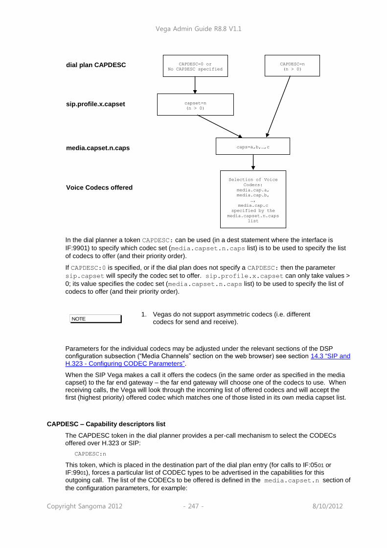
Vega Admin Guide R8.8 V1.1
Copyright Sangoma 2012 - 247 - 8/10/2012
In the dial planner a token CAPDESC: can be used (in a dest statement where the interface is
IF:9901) to specify which codec set (media.capset.n.caps list) is to be used to specify the list
of codecs to offer (and their priority order).
If CAPDESC:0 is specified, or if the dial plan does not specify a CAPDESC: then the parameter
sip.capset will specify the codec set to offer. sip.profile.x.capset can only take values >
0; its value specifies the codec set (media.capset.n.caps list) to be used to specify the list of
codecs to offer (and their priority order).
1. Vegas do not support asymmetric codecs (i.e. different
codecs for send and receive).
Parameters for the individual codecs may be adjusted under the relevant sections of the DSP configuration subsection (“Media Channels” section on the web browser) see section 14.3 “SIP and H.323 - Configuring CODEC Parameters”.
When the SIP Vega makes a call it offers the codecs (in the same order as specified in the media capset) to the far end gateway – the far end gateway will choose one of the codecs to use. When receiving calls, the Vega will look through the incoming list of offered codecs and will accept the first (highest priority) offered codec which matches one of those listed in its own media capset list.
CAPDESC – Capability descriptors list
The CAPDESC token in the dial planner provides a per-call mechanism to select the CODECs offered over H.323 or SIP:
CAPDESC:n
This token, which is placed in the destination part of the dial plan entry (for calls to IF:0501 or IF:9901), forces a particular list of CODEC types to be advertised in the capabilities for this outgoing call. The list of the CODECs to be offered is defined in the media.capset.n section of
the configuration parameters, for example:
NOTE
dial plan CAPDESC CAPDESC=0 or
No CAPDESC specified CAPDESC=n
(n > 0)
sip.profile.x.capset capset=n
(n > 0)
media.capset.n.caps caps=a,b,…,c
Voice Codecs offered
Selection of Voice
Codecs:
media.cap.a,
media.cap.b,
…,
media.cap.c
specified by the
media.capset.n.caps
list
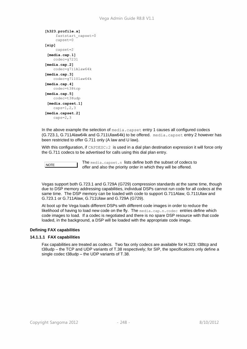
Vega Admin Guide R8.8 V1.1
Copyright Sangoma 2012 - 248 - 8/10/2012
[h323.profile.x]
faststart_capset=0
capset=0
[sip]
capset=2
[media.cap.1]
codec=g7231
[media.cap.2]
codec=g711Alaw64k
[media.cap.3]
codec=g711Ulaw64k
[media.cap.4]
codec=t38tcp
[media.cap.5]
codec=t38udp
[media.capset.1]
caps=1,2,3
[media.capset.2]
caps=2,3
In the above example the selection of media.capset entry 1 causes all configured codecs
(G.723.1, G.711Alaw64k and G.711Ulaw64k) to be offered. media.capset entry 2 however has
been restricted to offer G.711 only (A law and U law).
With this configuration, if CAPDESC:2 is used in a dial plan destination expression it will force only
the G.711 codecs to be advertised for calls using this dial plan entry.
The media.capset.n lists define both the subset of codecs to offer and also the priority order in which they will be offered.
Vegas support both G.723.1 and G.729A (G729) compression standards at the same time, though due to DSP memory addressing capabilities, individual DSPs cannot run code for all codecs at the same time. The DSP memory can be loaded with code to support G.711Alaw, G.711Ulaw and G.723.1 or G.711Alaw, G.711Ulaw and G.729A (G729).
At boot up the Vega loads different DSPs with different code images in order to reduce the
likelihood of having to load new code on the fly. The media.cap.n.codec entries define which
code images to load. If a codec is negotiated and there is no spare DSP resource with that code loaded, in the background, a DSP will be loaded with the appropriate code image.
Defining FAX capabilities
14.1.1.1 FAX capabilities
Fax capabilities are treated as codecs. Two fax only codecs are available for H.323: t38tcp and t38udp – the TCP and UDP variants of T.38 respectively; for SIP, the specifications only define a single codec t38udp – the UDP variants of T.38.
NOTE
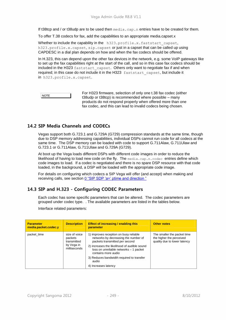
Vega Admin Guide R8.8 V1.1
Copyright Sangoma 2012 - 249 - 8/10/2012
If t38tcp and / or t38udp are to be used then media.cap.n entries have to be created for them.
To offer T.38 codecs for fax, add the capabilities to an appropriate media.capset.x
Whether to include the capability in the h323.profile.x.faststart_capset,
h323.profile.x.capset, sip.capset or just in a capset that can be called up using
CAPDESC in a dial plan depends on how and when the fax codecs should be offered.
In H.323, this can depend upon the other fax devices in the network, e.g. some VoIP gateways like to set up the fax capabilities right at the start of the call, and so in this case fax codecs should be
included in the H323 faststart_capset. Others only want to negotiate fax if and when
required; in this case do not include it in the H323 faststart_capset, but include it
in h323.profile.x.capset.
For H323 firmware, selection of only one t.38 fax codec (either t38udp or t38tcp) is recommended where possible – many products do not respond properly when offered more than one fax codec, and this can lead to invalid codecs being chosen.
14.2 SIP Media Channels and CODECs
Vegas support both G.723.1 and G.729A (G729) compression standards at the same time, though due to DSP memory addressing capabilities, individual DSPs cannot run code for all codecs at the same time. The DSP memory can be loaded with code to support G.711Alaw, G.711Ulaw and G.723.1 or G.711Alaw, G.711Ulaw and G.729A (G729).
At boot up the Vega loads different DSPs with different code images in order to reduce the
likelihood of having to load new code on the fly. The media.cap.n.codec entries define which code images to load. If a codec is negotiated and there is no spare DSP resource with that code loaded, in the background, a DSP will be loaded with the appropriate code image.
For details on configuring which codecs a SIP Vega will offer (and accept) when making and receiving calls, see section 0 “SIP SDP „a=‟ ptime and direction ”
14.3 SIP and H.323 - Configuring CODEC Parameters
Each codec has some specific parameters that can be altered. The codec parameters are grouped under codec type. . The available parameters are listed in the tables below.
Interface related parameters:
Parameter media.packet.codec.y
Description Effect of increasing / enabling this parameter
Other notes
packet_time size of voice packets transmitted by Vega in milliseconds
1) improves reception on busy reliable networks by decreasing the number of packets transmitted per second
2) increases the likelihood of audible sound loss on unreliable networks – 1 packet contains more audio
3) Reduces bandwidth required to transfer audio
4) Increases latency
The smaller the packet time the higher the perceived quality due to lower latency
NOTE

Vega Admin Guide R8.8 V1.1
Copyright Sangoma 2012 - 250 - 8/10/2012
Packet Profile
Within each codec defininition, e.g. media.cap.4 (by default G.279) there is a packet profile parameter. The packet profile defines the characteristics such as jitter buffer, echo canceller and whether out of band DTMF should be used. There are different profiles for voice and data calls as these have different requirements. For instance, for data calls echo cancellation should be disabled.
The following table shows the packet profile parameters:
Parameter dsp.xxx Description Effect of increasing / enabling this parameter
Other notes
VP_FIFO_nom_playout
minimum jitter buffer size in milliseconds
1) improves audibility of received audio when interworking with software based codecs (e.g. Microsoft Netmeeting) which introduce permanent jitter.
2) Improves audibility of received audio when connecting over the internet, or other data networks where there is significant jitter.
3) Increases the delay for the voice path
Set this value >= 2 to 3 times the “packet time” or to the maximum observed jitter on the LAN network plus 1 “packet time” (whichever is the larger value) – but do not set it larger than it needs to be; the larger the value the larger the latency, and the lower the perceived quality.
VP_FIFO_max_playout
maximum jitter buffer size in milliseconds
1) improves the audibility on data networks which introduce random amounts of jitter.
2) In cases of large jitter this will increase voice path delay
This value defines the maximum size the FIFO can dynamically grow to – leave this set at maximum for best results
out_of_band_DTMF out of band DTMF tone enable / disable
When enabled:
1) introduces a slight fixed delay into the voice path
2) the Vega detects and deletes the DTMF tones from the Audio stream that is to be sent across the LAN – it sends messages across the signaling link to tell the far end what DTMF tones it detected. The far end Vega will then re-generate the tones so that they are pure to the destination.
Need to use out_of_band_DTMF for G.723.1 as it compresses audio so much that when audio is expanded at the far end the tones are not accurately reproduced.
For G.711 and G.729 out_of_band_DTMF may be selected or not as desired.
Echo_tail_size amount of echo cancellation used in milliseconds
1) eliminates echo up to length selected
2) introduces fixed length delay of length selected
Leave at the default of 16ms unless echo is a problem. If it is increase to 32, 64 or 128 as proves necessary
TDM Profile
Within each TDM interface is configuration that refers to a packet profile. This defines the DSP characteristics for that interface or group of interfaces.
Vega Admin Guide R8.8 V1.1
Copyright Sangoma 2012 - 251 - 8/10/2012
14.4 G.729 / G.729 Annex A/B Codecs
The G.729 Codec is variously known as G.729, G.729 Annex A and G.729 Annex B, or even G.729 Annex A/B. G.729 is the original codec name, and also the generic name. Annex A introduced a codec which is interoperable with G.729 but is mathematically a lot less complex (therefore much more affordable in terms of DSP processing power). Annex B then added the optional (programmable) silence suppression. Vega gateways use the G.729 Annex A/B version of codec, whether the G.729 or G.729 Annex A variety is selected as it is backward compatible with the other variants:
H.323
Two codec names G.729 and G.729 Annex A are supported by the Vega for backward compatibility. In H.323 some products negotiate for a codec called G.729AnnexA (as defined in the H.323 specification), others for a codec named G.729 (not per specification). Vegas allow negotiation for both codecs. By allowing each to be selected as a separate codec, different parameters can be provisioned for the two.
SIP
RTP/AVP in SIP sdps is configured as a numeric value, 18 for G.729. In Vega gateways this enables a G.729 Annex A/B codec which is backward compatible with both G.729 and G.729 Annex A. Enabling G.729 or G.729 Annex A in media.cap.n will ensure that there are G.729 Annex A/B codecs immediately available for use (see section 14.2 “SIP Media Channels and CODECs”).
To change the parameters for the SIP G.729 codec, change the parameters in the G.729 section (not the ones in the G.729 Annex A section).
14.5 Out of band DTMF (OOB DTMF)
Compression CODECs such as G.723.1 and to a lesser extent G.729 distort audio because they must lose information in order to perform the compression. For normal speech this distortion is insignificant and hardly affects the intelligibility of the speech. However, in the case of pure tones (such as DTMF) this distortion modifies the tones enough that they are no longer within specification, and so DTMF detectors may not recognise the tones. The solution is to detect the tones before the audio is compressed, remove the tones from the audio stream and send the DTMF information as separate packets – out of the audio stream – to the far endpoint, which will then generate a pure DTMF tone back into the audio stream.
Such a mechanism is known as out of band DTMF, and is supported in all Vega products (SIP and H.323) for both transmission and reception.
By default the feature is enabled for all CODECs except G.711 A and u law (G.711 codecs will pass DTMF tones through uncorrupted). To change the setting use the
media.packet.codec.y.out_of_band_DTMF parameter in the configuration database.
To monitor the passing of DTMF from LAN to telephony and vice versa, the “log display v”
command can be used. The output of this command is similar to the below:
LOG: 28/10/2010 12:04:20.465 RFC2833 (V)R29C00 [f100017f](RFC2833) sending digit
'1'
LOG: 28/10/2010 12:04:20.470 RFC2833 (V)R28C00 [f100017e](RFC2833) receiving
digit '1'
NOTE

Vega Admin Guide R8.8 V1.1
Copyright Sangoma 2012 - 252 - 8/10/2012
LOG: 28/10/2010 12:04:21.077 RFC2833 (V)R29C00 [f100017f](RFC2833) sending digit
'5'
LOG: 28/10/2010 12:04:21.092 RFC2833 (V)R28C00 [f100017e](RFC2833) receiving
digit '5'
H.323 out of band DTMF
In H.323, Out-of-band DTMF information is sent in H.245 UserInputIndication messages – they can be sent in two formats: “alphanumeric or simple mode”, and “signal mode”. Vega gateways will accept OOB DTMF messages generated in either format. By default Vega gateways will use the “signal” type format to send OOB DTMF information, but this can be configured in the following configuration parameter:
[h323.profile.x]
oob_method=signal ; alphanumeric=alphanumeric/simple; signal=signal;
none=none
“Alphanumeric / simple mode” does not support DTMF tone duration information.
“Signal mode” supports optional timing information. (However, Vega gateways do not send timing information, and ignore any received timing information).
SIP out of band DTMF
In SIP, Out-of-band DTMF information can either be sent in Info messages, or from using RFC2833.
For further details on RFC 2833 see section 16.6 “RFC2833”
For further details on Info messages see the SIP Signalling Messages Appendix.
14.6 Tones
Configuring Local Call Progress Tones
During call establishment, and usually during call disconnection the caller hears call progress tones. These tones include: busy tone, ringing tone, unobtainable, etc. Sometimes these are generated by the Network, sometimes the Vega passes the audio through from another device and sometimes the Vega generates the call progress tones itself.
Because each tone cadence may vary from country to country, the Vega provides a facility for the user to change their definition. Configuration is via a three tiered set of configuration parameters, [tones], [tones.def] and [tones.seq]. These parameters can be configured directly through a CLI interface or via the web browser from the menu “tones”.
The [tones] section provides a mapping of the call progress tones that the Vega offers to specific tone sequence IDs:
[tones]
dialtone_seq=1 ; general dial tone for making calls
stutterd_seq=2 ; stutter dial tone (not implemented on H.323)
busytone_seq=3 ; busy tone on cause 17
fastbusy_seq=4 ; fast busy tone for number not found
ringback_seq=5 ; ringback tone for far end ringing
callwait1_seq=6 ; call waiting tone 1 (not implemented on H.323)
callwait2_seq=7 ; call waiting tone 2 (not implemented on H.323)
The [tones.seq] section specifies the sequences. For each sequence ID the list of raw tones, their duration and their order are specified. The duration value is measured in milliseconds; a
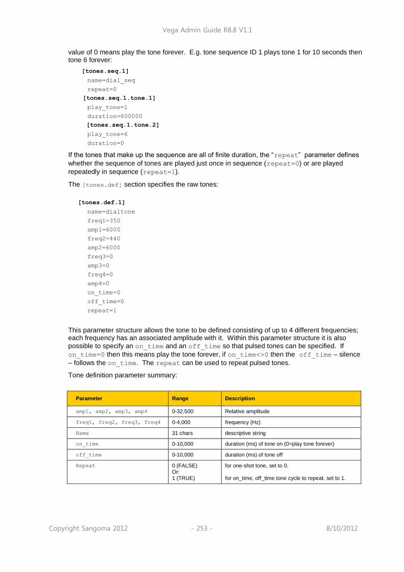
Vega Admin Guide R8.8 V1.1
Copyright Sangoma 2012 - 253 - 8/10/2012
value of 0 means play the tone forever. E.g. tone sequence ID 1 plays tone 1 for 10 seconds then tone 6 forever:
[tones.seq.1]
name=dial_seq
repeat=0
[tones.seq.1.tone.1]
play_tone=1
duration=600000
[tones.seq.1.tone.2]
play_tone=6
duration=0
If the tones that make up the sequence are all of finite duration, the “repeat” parameter defines
whether the sequence of tones are played just once in sequence (repeat=0) or are played
repeatedly in sequence (repeat=1).
The [tones.def] section specifies the raw tones:
[tones.def.1]
name=dialtone
freq1=350
amp1=6000
freq2=440
amp2=6000
freq3=0
amp3=0
freq4=0
amp4=0
on_time=0
off_time=0
repeat=1
This parameter structure allows the tone to be defined consisting of up to 4 different frequencies; each frequency has an associated amplitude with it. Within this parameter structure it is also
possible to specify an on_time and an off_time so that pulsed tones can be specified. If
on_time=0 then this means play the tone forever, if on_time<>0 then the off_time – silence
– follows the on_time. The repeat can be used to repeat pulsed tones.
Tone definition parameter summary:
Parameter Range Description
amp1, amp2, amp3, amp4 0-32,500 Relative amplitude
freq1, freq2, freq3, freq4 0-4,000 frequency (Hz)
Name 31 chars descriptive string
on_time 0-10,000 duration (ms) of tone on (0=play tone forever)
off_time 0-10,000 duration (ms) of tone off
Repeat 0 (FALSE) Or: 1 (TRUE)
for one-shot tone, set to 0. for on_time, off_time tone cycle to repeat, set to 1.
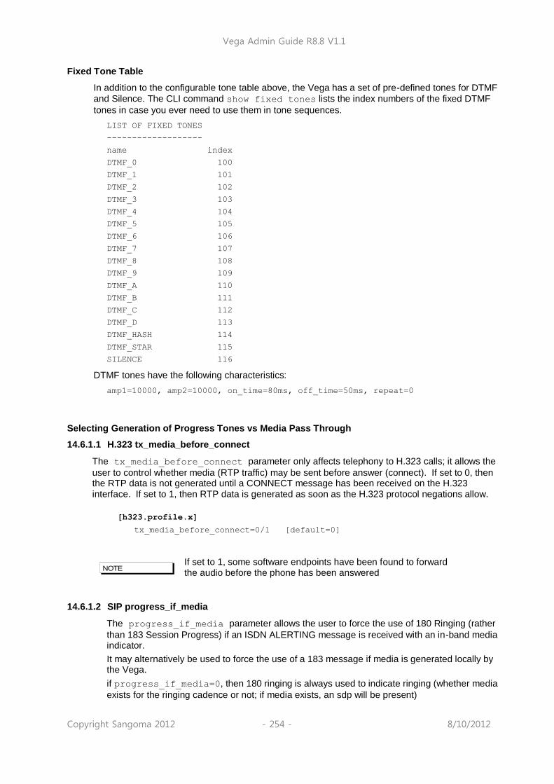
Vega Admin Guide R8.8 V1.1
Copyright Sangoma 2012 - 254 - 8/10/2012
Fixed Tone Table
In addition to the configurable tone table above, the Vega has a set of pre-defined tones for DTMF
and Silence. The CLI command show fixed tones lists the index numbers of the fixed DTMF
tones in case you ever need to use them in tone sequences.
LIST OF FIXED TONES
-------------------
name index
DTMF_0 100
DTMF_1 101
DTMF_2 102
DTMF_3 103
DTMF_4 104
DTMF_5 105
DTMF_6 106
DTMF_7 107
DTMF_8 108
DTMF_9 109
DTMF_A 110
DTMF_B 111
DTMF_C 112
DTMF_D 113
DTMF_HASH 114
DTMF_STAR 115
SILENCE 116
DTMF tones have the following characteristics:
amp1=10000, amp2=10000, on_time=80ms, off_time=50ms, repeat=0
Selecting Generation of Progress Tones vs Media Pass Through
14.6.1.1 H.323 tx_media_before_connect
The tx_media_before_connect parameter only affects telephony to H.323 calls; it allows the
user to control whether media (RTP traffic) may be sent before answer (connect). If set to 0, then the RTP data is not generated until a CONNECT message has been received on the H.323 interface. If set to 1, then RTP data is generated as soon as the H.323 protocol negations allow.
[h323.profile.x]
tx_media_before_connect=0/1 [default=0]
If set to 1, some software endpoints have been found to forward the audio before the phone has been answered
14.6.1.2 SIP progress_if_media
The progress_if_media parameter allows the user to force the use of 180 Ringing (rather
than 183 Session Progress) if an ISDN ALERTING message is received with an in-band media indicator.
It may alternatively be used to force the use of a 183 message if media is generated locally by the Vega.
if progress_if_media=0, then 180 ringing is always used to indicate ringing (whether media
exists for the ringing cadence or not; if media exists, an sdp will be present)
NOTE

Vega Admin Guide R8.8 V1.1
Copyright Sangoma 2012 - 255 - 8/10/2012
if progress_if_media=1, then if media exists for the ringing a 183 Session Progress will be
used (instead of the 180 Ringing). If no media is available for ringing, (in ISDN a flag indicates whether or not there is inband audio) then a 180 Ringing will be used. Note this acts upon the indicator in the ISDN messaging and is not overridden by the decision to generate tones locally (tones.net.ring=1)
if progress_if_media=2, then if media exists, either from the incoming call, or generated
locally (tones.net.ring=1) 183 with sdp will be used, otherwise if no media a 180 will be used.
In each case RTP audio will be sent as soon as SDPs are agreed and media is available.
[_advanced.sip]
progress_if_media=0/1/2 [default=2]
To see how this parameter interacts with others for an FXS interface, see table in 14.6.1.5 “FXS SIP parameters for ringback generation to the VoIP interface”
To see how this parameter interacts with others for an ISDN interface see table in 14.6.1.6.1 “

Vega Admin Guide R8.8 V1.1
Copyright Sangoma 2012 - 256 - 8/10/2012
ISDN SIP parameters for ringback generation to the VoIP interface”
14.6.1.3 Network (Remote) Call Progress Tones (SIP gateways only)
It is possible to configure a SIP Vega to generate call progress tones that are played back over the LAN, for scenarios where it is not possible to generate the progress tones at the “local” end.
14.6.1.3.1 Tone Types
When configured (see section 14.6.1.3.5 “Configuration Parameters for Network Tones (SIP only)”) there are 3 kinds of tones that can be played:
1) ringback - normal ringback tone
2) failure - tone played when call couldn‟t be made e.g. due to "engaged" or "unreachable"
3) disconnect - tone played when call was hung-up at the far end first.
14.6.1.3.2 Ringback Tone
For example, when a user A makes a VoIP call to / through the Vega, he / she can hear the ringback tone generated by the remote Vega.
User A on User B on
SIP phone-----LAN------Vega
<------(sends ringback using RTP)
14.6.1.3.3 Failure Tones
For example, remote user engaged:
1) User A calls User B.
2) User B is engaged.
3) User A hears the busy tone generated by the Vega.
User A on User B on
SIP phone-----LAN------Vega
<------(sends busy tone using RTP)
14.6.1.3.4 Disconnect Tones
For example, remote user hangs up first:
1) User A calls User B.
2) User B answers and then hangs up
3) User A hears the busy tone generated by the Vega
User A on User B on
SIP phone-----LAN------Vega
<------(sends busy tone using RTP)
14.6.1.3.5 Configuration Parameters for Network Tones (SIP only)
Network tones are enabled using the following parameters:
[tones.net]
ring=1 ;set to '1' to enable playing of ringback tone towards packet network

Vega Admin Guide R8.8 V1.1
Copyright Sangoma 2012 - 257 - 8/10/2012
The tones definitions used for the Network call progress tones are:
Network tone Use tone defined by
Ringback tones.ringback_seq
Failure tones.busytone_seq
disconnect tones.busytone_seq
14.6.1.4 Vega FXO ringback_present
The ringback_present parameter is designed for use on line current reversal lines to
control whether during outdial the calling party hears ringback tone, or whether they hear the dial tone, outdial and any progress tones.
[_advanced.pots.fxo.x]
ringback_present=0/1 [default=1]
If ringback_present=0, on an FXO outbound call ringback tone is passed to the VoIP
interface until the FXO answer is received
If ringback_present=1, on an FXO outbound call, audio from the FXO line is passed
across the VoIP interface as soon “early media” allows audio to be transferred
On standard loopstart lines, the “answer” occurs on seizing the FXO line, so all dialling etc. will be heard whatever the value of this parameter. On line current reversal lines ringback tone will be heard until answer if this parameter is set to 0.
14.6.1.5 FXS SIP parameters for ringback generation to the VoIP interface
The following table shows the interaction of various parameters with the generation of ringback tone to the SIP interface.
Tones.net.ring _advanced.sip. progress_if_media Result
Generate ringback tone to packet network when Alerting
0: Force use of180 if alerting 1: Use 183 rather than 180 if media present in alerting 2: Use 183 if either in-band or locally generated media
0 0 180 (no sdp)
1, 2 183 (no sdp)
1 0, 1 180 with sdp; Locally generated ringback
2 183 with sdp; Locally generated ringback
14.6.1.6 ISDN
Configuration parameters are available to allow control over the playing of dial tone and in-band progress tones from the Vega.
E1T1s configured as NT generate dial tone and progress tones by default, but _advanced.isdn.force_disconnect_progress still needs to be configured to define the maximum time to play disconnect tone at the end of a call.
NOTE
NOTE

Vega Admin Guide R8.8 V1.1
Copyright Sangoma 2012 - 258 - 8/10/2012
[_advanced.isdn]
user_dialtone=0/1 [default=0]
set to 1 configures TE E1T1s on ISDN interfaces to originate dial tone towards an NT device.
[_advanced.isdn]
user_progress=0/1 [default=0] set to 1 configures TE E1T1s on ISDN interfaces to originate progress tones towards an NT device, for both DISCONNECT and ALERTING messages.
[_advanced.isdn]
alert_with_progress=0/1/2 [default=1] Set to 0 causes the Vega to ignore any „In-band Media‟ indication in ISDN Alerting messages (media is not cut through at this stage) Set to 1 causes the Vega to act upon any „In-band Media‟ indication in ISDN Alerting messages (media is cut through if in-band media is indicated) Set to 2 causes the Vega to Assume „In-band Media‟ on receiving an ISDN Alerting message (media is cut through immediately after the Alerting message has been received).
[_advanced.isdn]
progress_with_progress=0/1/2 [default=1] Set to 0 causes the Vega to ignore any „In-band Media‟ indication in ISDN Progress messages (media is not cut through at this stage) Set to 1 causes the Vega to act upon any „In-band Media‟ indication in ISDN Progress messages (media is cut through if in-band media is indicated) Set to 2 causes the Vega to Assume „In-band Media‟ on receiving an ISDN Progress message (media is cut through immediately after the Progress message has been received).

Vega Admin Guide R8.8 V1.1
Copyright Sangoma 2012 - 259 - 8/10/2012
[_advanced.isdn]
send_progress_as_alerting=0/1 [default=0] Set to 0 allows progress messages to be passed through unchanged Set to 1 causes received progress messages from ISDN interfaces to be converted to alerting messages before being forwarding onto the VoIP interface or another ISDN interface.

Vega Admin Guide R8.8 V1.1
Copyright Sangoma 2012 - 260 - 8/10/2012
14.6.1.6.1 ISDN SIP parameters for ringback generation to the VoIP interface
The following table shows the interaction of various parameters with the generation of, or passing through of ringback tone to the SIP interface.
ISDN messaging
_advanced.isdn. alert_with_progress
_advanced.isdn. progress_with_progress
_advanced.isdn.send_progress_as_ alerting
Tones.net.ring _advanced.sip. progress_if_media
Result
Alert message with Progess Indicator 0: do not pass media through 1: pass through media if in-band media indicated 2: assume media is present and pass it through even if not indicated in signalling
Progress message with Progress Indicator 0: do not pass media through 1: pass through media if in-band media indicated 2: assume media is present and pass it through even if not indicated in signalling
Treat an incoming ISDN progress message as though it were an Alerting message.
Generate ringback tone to packet network if Alerting or Progress is received, provided that no media is indicated.
0: Force use of180 if alerting 1: Use 183 rather than 180 if media present in original ISDN alerting or progress message 2: Use 183 if either in-band media or locally generated media is present
Alerting (no media)
0, 1 X X 0 0 180 (no sdp)
1, 2 183 (no sdp)
1 0, 1 180 with sdp; Generated ringback
2 183 with sdp; Generated ringback
2 … As Alerting (with media)
Alerting (with
media)
0 … As Alerting (no media)
1, 2 X X X 0 180 with sdp; ISDN media
1, 2 183 with sdp; ISDN media
Progress (no media indicated)
X 0, 1 0 0 X 180
(no sdp)
1 0,1 180 with sdp; Generated ringback
2 183 with sdp; Generated ringback
1 As Alerting (no media)
2 As Progress (with media)
Progress (with media)
0 0 0 X X 180
(no sdp)
1, 2 0 X X 183 with sdp; ISDN media
X 1 … As Alerting (no media)
1, 2 0 0 X X 180 (no sdp)
1, 2 0 X X 183 with sdp; ISDN media
X 1 … As Alerting (with media)

Vega Admin Guide R8.8 V1.1
Copyright Sangoma 2012 - 261 - 8/10/2012
14.6.1.7 CAS SIP parameters for ringback generation to the VoIP interface
The following table shows the interaction of various parameters with the generation of ringback tone to the SIP interface.
On setting up a call, after the CAS dialling is complete the Vega CAS code sends a progress message – with no media indication – to SIP.
e1t1.port.x.rbs.progress_tones_present tones.net.ring Result
0: Indicate no progress tone 1: Indicate progress tone
Generate ringback tone to packet network when Alerting or Progress is received, provided that no media is indicated.
0 0 180 (no sdp)
1 183 with sdp: Generated ringback
1 x 183 with sdp: CAS media
14.6.1.8 Disconnect With Media
Digital Vega gateways can now handle disconnect with progress messages before the answer state. In these cases the Vega will optionally use a 183 Progress Message to carry the ISDN media. The parameter that controls this behaviour is as follows:
_advanced.sip.disc_with_progress
Possible values:
0 – Default – Do not pass ISDN media
1 to 6000 – Play ISDN media for the specified time (seconds)

Vega Admin Guide R8.8 V1.1
Copyright Sangoma 2012 - 262 - 8/10/2012
14.6.1.9 Symmetric RTP / Dynamic RTP
Symmetric RTP / Dynamic RTP allows the Vega to be configured so that it monitors the incoming audio RTP stream for a call and makes sure that the RTP it sends out is sent back to that same IP address as the media is received from. This helps traverse firewalls where the sender does not properly define the outside IP address of the firewall in its SIP sdp. Receiving RTP audio data from an IP port and / or IP address that is different from that indicated in the SDP is not a problem for the Vega receiving the RTP traffic. If however the Vega sends its RTP traffic back to the originator using the IP address / IP port specified in the SDP it is unlikely to get through the NAT as the NAT will only route data back to the sender if it is received on the same IP address / IP port that the RTP traffic is sent from. In order to handle this, it is necessary for the Vega receiving the RTP to detect the IP port / IP address that it is receiving the RTP traffic from and return the RTP traffic back to that IP port / IP address.
[media.control.1.dynamic_update] enable=1 ; enable frequency=n ; a value of 0 means that only the first received RTP
packet will be checked. A value of 1 means that every packet will be checked, a value of 2 means that every other packet will be checked …
ip_follow=1 ; set to 1 to allow IP address and IP port following private_subnet_list_index=0 ; defines list of allowable IP addresses to follow
If Symmetric RTP is needed, audio cannot be received by the device whose RTP is being NATed differently from that defined in the SDP, until the far end has received RTP traffic from that device (as it is not until the RTP traffic is received that the returned RTP traffic can be sent to the correct IP port / IP address). This means that early audio may be lost – as initially it will be sent to the wrong destination IP port / IP address (the IP port / IP address specified in the SDP).
WARNING!
Checking every packet for a change of IP details is processor intensive – benchmark your system if you set dynamic_update_freq to anything other than zero
NOTE

Vega Admin Guide R8.8 V1.1
Copyright Sangoma 2012 - 263 - 8/10/2012
15 FAX, MODEM AND DATA CALLS
15.1 Fax and Modem Operation
In the same way that DTMF tones can be compressed so much that when uncompressed they are out of specification, so can group 3 fax and modem transmissions. This causes fax / modem tone recognition problems and therefore failed fax / modem calls.
Vega gateways support both T.38 and G.711 up-speeding to allow fax and modem calls to succeed:
T.38 is an ITU-T standard defining how to carry group 3 fax transmissions as out of band packets over an IP network (this only supports fax communications, it does not support direct modem communications).
Super G3 faxes – using modem signalling > 33 kbps – and non-fax modems require connection via G.711.
Call flow:
Vega gateways will always connect initially using the preferred voice codec. If fax or modem detection is enabled (see below for details) then the Vega will monitor for these in-band tones.
When detected, depending on the configuration of the Vega and the tones heard (modem and fax, or just modem) the Vega will connect using T.38, or up-speed to a data mode G711 codec.
1. As per the standards: H.323 Vega gateways support both TCP and UDP T.38 SIP Vega gateways support UDP T.38 (SIP Annex D T.38) and also SIP Annex E (voice and fax codec negotiated so no re-invite needed)
2. Once switched to T.38 mode the Vega will not automatically revert back to voice mode (it needs a VoIP request to change back to a voice codec).
3. Vega gateways support connection rates up to 14.4 kbps when using T.38 (faster connection rates require G.711 data mode)
For further details on the T.38 protocol see Information Note IN_06-T38 protocol interactions.
WARNING!
If you have problems getting fax / modem communications working look out for the following Gotchas:
1. Delays introduced by the data network can create problems with the fax handshaking. This is because, although tones are detected and regenerated at the VoIP gateways, the handshaking is passed between the end fax machines.
2. If the clocking of the source and destination VoIP gateways is not synchronised by say connection of the gateways to digital trunks on the PSTN, then they will run at independent clock speeds. Over time, internal buffers will overflow or underflow due to the difference in clock (data)
NOTE

Vega Admin Guide R8.8 V1.1
Copyright Sangoma 2012 - 264 - 8/10/2012
rates. This will cause the fax machines / modems to have to re-negotiate. If the slip is too great then re-negotiation will take more time than data transmission time and connections are likely to fail.
SIP handling of Fax and modem calls
Fax machines and modems only send tones once a call is in progress, so initially a VoIP call will be
set up using a codec specified in media.capset.x.caps. If fax and modem detection is
enabled the Vega will then monitor for fax and modem tones. If they are detected, the Vega will do its best to get the fax / modem call through to the destination, by using either T.38, if enabled, and if it is supported by the other endpoint device (and the call is a a fax call), otherwise using a G.711 data codec (g.723.1 and G.729 will not pass fax or modem calls). On detecting the fax tones the Vega first sends a Re-INVITE to the other SIP device with T.38 in the SDP. If the other end cannot support T.38 then it will reject this Re-INVITE and the Vega will send another Re-INVITE, this time offering to use G.711U-law and G.711A-law. If both Re-INVITE's are rejected then the call will be terminated. If the call is a modem call the INVITE with T.38 will be omitted. If SIP Annex E is enabled (sip.t38_annexe_use / sip.t38_annexe_accept) and agreed
during sdp negotiation, then the re-invite stage is omitted; when the fax call is detected the media can be swapped to T.38 immediately. Some endpoints are sensitive to the SIP header information supplied when making T.38 connections – if problems occur, try making the following Vega parameter changes:
[_advanced.sip.sdp]
sess_desc_connection=1
t38_single_media=1
Some fax machines have integrated phone handsets. If a voice call is made between two such machines (and the call is routed via a Vega gateway over SIP), then a FAX is sent on the same call; if the handsets remain off-hook the two parties can talk to one another again after the FAX call has been sent. This will result in the Vega transmitting a further SIP re-INVITE to switch back to a voice codec.
For more details on the operation of the T.38 protocol see IN_06-T38 protocol interactions.
H.323 handling of Fax and modem calls
Fax machines and modems only send tones once a call is in progress, so initially a VoIP call will be set up using a codec specified in the media.capset.x.caps. Typically this capset will be the
„faststart‟ capset and will not include any fax or modem codecs. If the Vega detects any fax / modem tones and the „non-faststart‟ capset includes any fax / modem handling codecs, the Vega will do its best to get the fax / modem call through to the destination, by using either T.38 (tcp or udp – whichever is enabled), if it is supported by the other endpoint device (and the call is a a fax call), otherwise using a G.711 data codec (g.723.1 and G.729 will not pass fax or modem calls).

Vega Admin Guide R8.8 V1.1
Copyright Sangoma 2012 - 265 - 8/10/2012
On detecting fax or modem tones the Vega closes the voice „logical channel‟ and starts media negotiations to open the relevant T.38 and / or G.711 „logical channel‟ (whichever is included in the non-faststart capset). If this new media negotiation fails then the call will be terminated. Some gateways (like Vega gateways) allow T.38 to be included in the original faststart. It is possible that both a voice and a T.38 channel will be accepted. Under this condition, there is no need to re-negotiate codecs when fax is detected, fax media will just be sent down the T.38 logical channel, and voice media will no longer be sent down the voice channel when fax is detected.
When using T.38 use of fast_start is not mandatory, in
fact Sangoma‟s recommended configuration is to enable early_h245 and disable fast_start
For more details on the operation of the T.38 protocol see IN_06-T38 protocol interactions.
15.2 Configuration Parameters for fax / modem handling
[sip]
enable_modem=1 ; Allow low speed modems to be detected and
; up-speed to G.711 instead of using T.38
fax_detect=terminating ; At which end of the VoIP link should fax
; tones be looked for
modem_detect=terminating ; At which end of the VoIP link should
; modem tones be looked for
T38_annexe_accept=0 ; Accept T.38 Annex E requests
T38_annexe_use=0 ; Initiate T.38 Annex E requests
[dsp.t38]
cd_threshold=-33 ; Threshold for Carrier Detect signal (db)
FP_FIFO_nom_delay=300 ; Fax Play-out FIFO nominal delay (ms)
network_timeout=150 ; Time before cleardown if packets stop
packet_time=40 ; Packet size in milliseconds
rate_max=144 ; Max fax rate bps/100
rate_min=24 ; Min fax rate bps/100
rate_step=24 ; Step size in fax rates
timeout=15 ; No Activity timeout
tx_level=-8 ; Fax Modem Transmit Level (0:-13dB)
[media.packet.t38tcp.x]
max_rate=144 ; Preferred max fax rate bps/100
tcf=local ; T.38 fax training mode
[media.packet.t38udp.x]
max_rate=144 ; Preferred max fax rate bps/100
tcf=transferred ; T.38 fax training mode
[_advanced.dsp]
fax_disconnect_delay ; Delay after receiving disconnect before
; clearing call
t38_diags=0 ; For engineering use only
[_advanced.dsp.buffering.fax]
depth=100 ; Buffer size
enable=0 ; Enable T.38 packet re-synch in buffer
[_advanced.media]
control_v25 = fax ; Force to fax mode if V25 tone is heard
NOTE

Vega Admin Guide R8.8 V1.1
Copyright Sangoma 2012 - 266 - 8/10/2012
[_advanced.t38]
allow_MR_page_compress=1 ; Do not suppress use of MR page
; compression
allow_ecm=1 ; Do not suppress Error Correction Mode
enable_Eflags_in_first_DIS=1 ; For Engineering use only
enable_TFoP=1 ; Do not disable repetition of
; FrameComplete packet
enable_scan_line_fix_up=1 ; Do not disable scan line fix-up
[_advanced.t38.tcp] (H323 Only) collect_hdlc ; Collect V.21 hdlc into packets
connect_on_demand=1 ; Connect T.38 when fax tones are detected
; (rather than on every call)
port_range_list=2 ; _advanced.lan.port_range_list that
; specifies t38 tcp ports
suppress_t30=0 ; Suppress transmission of some T.30
; indications
[_advanced.t38.udp]
check_start_packet=1 ; Only switch to fax mode when first fax
; packet has been received (allowing voice
; path to remain connected to that point)
port_range_list=3 ; _advanced.lan.port_range_list that
; specifies t38 udp ports
H.323 Vega gateways treat TCP T.38 and UDP T.38 as codec types. Enabling T.38 is carried out in the same manner as enabling audio codecs; see section 0 “Defining FAX capabilities”.
SIP gateways treat UDP T.38 as a codec type. Enabling T.38 is carried out in the same manner as enabling audio codecs; see section 0 “Defining FAX capabilities”.
More details on some of the key parameters:
[media.packet.t38tcp.x] (H323 only) tcf
The tcf parameter defines whether fax modem training is carried out at the local ends of the VoIP
link, or whether the training tones should be transferred across the VoIP link – for t38 tcp recommendations say keep training local
It is important that this value is configured the same at both ends of the VoIP call.
[media.packet.t38udp.x]
tcf
The tcf parameter defines whether fax modem training is carried out at the local ends of the VoIP
link, or whether the training tones should be transferred across the VoIP link – for t38 udp recommendations say transfer the training information across the VoIP link
It is important that this value is configured the same at both ends of the VoIP call.
[sip]
enable_modem
If enable_modem is set to 0, then the Vega will not support low speed modems; it will treat any
call which has low speed modem tones as a fax call. This setting can be used if it is known that all calls will be voice or fax calls and not modem calls.
If enable_modem is set to 1, then, on hearing low speed modem tones, the Vega will assume that
the call is a low speed modem call (and use G.711 rather than T.38) unless it detects the V.21 tone which confirms that the call is a fax call.
If enable_modem is set to 1, then even if G711 data codecs are not enabled in the active
media.capset.n.caps they may still be used.

Vega Admin Guide R8.8 V1.1
Copyright Sangoma 2012 - 267 - 8/10/2012
[sip]
fax_detect
modem_detect
The fax_detect and modem_detect parameters defines whether the Vega looks for fax and /
or modem tones: only from its telephony interface, from telephony and VoIP interfaces, or never.
It is generally better (and adheres to the standards) to only detect tones on one end of the call – the end terminating the VoIP call (initiating the call to the answering fax machine / modem); this is the end that hears the tones directly from the line (rather than having to detect tones that have passed through both the telephone line and through VoIP). If the far end 3
rd party gateway does
not detect the tones properly the Vega can be configured always to detect fax / modem tones, whether the call arrives on the Vega on its telephony interface or its VoIP interface.
[sip]
T38_annexe_accept
T38_annexe_use
T.38 Annex E allows media to change from Voice to T.38 without need for a re-invite. This speeds up the transition from voice mode to fax mode, and reduces the number of signalling messages required.
[_advanced.media]
control_v25
Setting v25_control to data causes the Vega to use G711 data codecs rather than T.38 for
transmission of modem and fax calls.
[_advanced.dsp.buffering.fax]
depth ; Buffer size
enable ; Enable T.38 packet re-synch in buffer
By default Vega gateways expect to see T.30 / T.38 messages arriving in sequence. With certain gateways (e.g. Cisco) the messages are not always sent out sequentially. By enabling
_advanced.dsp.buffering.fax the Vega can handle this. It re-orders the T.30 / T.38
messages into sequential order as it puts them in the buffer.
For details about other parameters, see the information in 7.7 “Configuration Entries”, and 7.8 “Advanced configuration entries”.
Recommended Values for SIP FAX / Modem Connectivity
For normal use with FAX and modems:
1. Enable the required audio codecs in the capset. Add T38udp, followed by one or both G711Alaw 64k – profile 2 and / or G711ulaw64k – profile 2.
2. set sip.enable_modem = 1
3. set _advanced.media.control_v25 = ignore
For use with G.711 Up-Speeding only, and no T.38:
1. Enable the required audio codecs in the capset. Add one or both G711Alaw 64k – profile 2 and / or G711ulaw64k – profile 2.
2. set sip.enable_modem = 1
3. set _advanced.media.control_v25 = data
For use with T.38 only, and no G711 Up-Speeding:
1. Enable the required audio codecs in the capset, add T38udp as the last entry.

Vega Admin Guide R8.8 V1.1
Copyright Sangoma 2012 - 268 - 8/10/2012
2. set sip.enable_modem = 0
3. set _advanced.media.control_v25 = fax
15.3 ISDN Unrestricted Digital Information Bearer Capability and Clear Mode
ISDN calls calls are tagged with a bearer capability identifying the type of media being carried. For standard Voice and fax calls, bearer capabilities of „voice‟ and „3.1KHz audio‟ are usually used.
One of the other bearer capabilities is Unrestricted Digital Information. In order to carry this type of media, standard voice compression / gain must not be applied. SIP variants of Vega code automatically force the codec type to use to clear mode when Unrestrictd Digital Information calls are received.
Clear mode (also known as octet codec) can also be specified in the capset to be used in cases where a bearer capability is not available or the one received does not specify Unrestricted Digital Information.
15.4 Super G3 FAX Operation
G3 FAXs operate at speeds up to 14400bps, above this speed and up to 33600bps Super G3 FAX is used. In default configuration the Vega will use T.38 for G3 FAXs and G.711 data for SG3 FAXs. There are advantages in using T.38 as it is more robust and resilient to imperfect networks.
Super G3 FAX‟s are capable of downspeeding to G3 as they must be capable of calling regular G3 FAXs. There is a facility in the Vega to force a SG3 FAX to downspeed so that T.38 can be used.
The Tones
The following tones are used in FAX and MODEM interaction but each can have multiple names depending on whether they are referenced in FAX standards (T.30) or MODEM standards (V.90 etc).
V.25 without Phase Reversals
Also known as CED (usually for FAX) and ANS (for MODEM). Used by G3 FAXs and MODEMs using the V.32bis standard. The fastest data speed for these types of devices is 14400bps.
V.25 with Phase Reversals
This is also known as ANSam - there are several variants depending on the information contained within the data of this tone.
V.21 Preamble
Used by the Vega as a definitive indication that a FAX is starting. After some initial handshaking this is the first signal sent (usually by the receiving FAX) to indicate that it is about to send data using the V.21 standard. What this consists of is a description of the capabilities of the FAX machine sending the tone. V.21 is not used in a Super G3 to Super G3 connection (or by MODEMs capable of greater then 14400bps) – other tones (such as the V.8 CM tone) are used instead. This is where the problem occurs on VoIP systems – spotting that a Super G3 FAX interaction is taking place and forcing the connection to use T.38 (or a slower data speed).
The Interactions
To stop the Super G3 FAXs negotiating directly, on detection of the V.25PR signal the Vega will mute media from the originating FAX to the terminating FAX – thus blocking the V.8 CM signal response to the V.25PR. According to the T.30 FAX standard the V.25PR signal is played for up to 4 seconds while waiting for the CM response. After this time the terminating FAX will drop to G3

Vega Admin Guide R8.8 V1.1
Copyright Sangoma 2012 - 269 - 8/10/2012
mode and follow the V.32bis standard – which means that very soon after the time out the V.21 preamble is detected.
Configuration
To allow the Vega to successfully change to T.38 or data mode if a Super G3 FAX or a MODEM faster then 14400bps call is in progress then the following settings are used.
_advanced.media.control_V25
This should be set to “ignore” if both FAX and MODEM calls are expected. Alternatively “fax” or “data” can be used to allow the Vega to more quickly decide on what type of connection to use. This config controls the responses to both the V.25PR and V.25 signals – see table below. It‟s possible that this configuration setting will not be needed in the future as the required actions are largely dependent on whether FAX and/or MODEM detection is required and this is determined by the application‟s (for example SIP) configuration.
_advanced.media.V21_wait_time
Time (in milliseconds) to wait after a V.25 tone is detected for a V.21 signal. After this time has expired without detecting V.21 the Vega will change to “data” mode. This setting can be from 1000ms to 10000ms. Normally it shouldn‟t be less than 3500 as that is the timeout for the V.25PR signal for Super G3 FAXs. The effect of the timeout is to unmute the media and switch to data mode. The timing of the unmuting may be critical for allowing the MODEMs to then negotiate correctly – this is for further investigation.
control_V25 setting
ignore Fax data
V.25 PR Mute the IP to TDM media. Start delay timer.
Mute the IP to TDM media. Start delay timer.
Switch to “data” mode to allow MODEMs to negotiate best speed.
V.25 Unmute media. Start timer if not already running.
Unmute media. Stop timer. Switch to T.38 mode.
Switch to “data” mode to allow MODEMs to negotiate best speed.
V.21 Switch to T.38 mode.
Switch to T.38 mode.
Switch to T.38 mode.
For the SIP configuration to detect FAX the “fax_detect” config should be set to terminating. Similarly for MODEM detection the “modem_detect” config should be set to terminating. These setting currently can also be set to always – this setting now does the same as “terminating” so may be dropped in future.
_advanced.sip.sdp.ecan_enable
_advanced.sip.sdp.silencesupp_enable
These should both be set to “1” to support data mode. Data mode (for MODEMs and in-band FAXing) requires that the signals are transported across VoIP without being changed to the Echo Canceller setting and Silence Suppression setting (both off for data mode) needs to be conveyed to the peer SIP UA. These settings have been left disabled to prevent and SIP interop issue.

Vega Admin Guide R8.8 V1.1
Copyright Sangoma 2012 - 270 - 8/10/2012
16 SIP GATEWAYS
This section describes the configuration and behaviour of SIP variants of the Vega gateway.
16.1 Introduction
The SIP firmware acts as a set of SIP User Agents within the Vega. Communication, by default, is via UDP unicast, usually to and from UDP port 5060. TCP connection for SIP signalling messages may also be configured. (Note audio – RTP – traffic is always UDP).
All Request URI usernames are of the form sip:telephone_number and all hosts are
expressed as numerical IP addresses, or domain names if DNS is configured, in which case lan.name must be set to the Vega‟s DNS hostname.
The SIP module supports remote commands for re-INVITE, hold and retrieve, transfer via the BYE-Also mechanism and also the REFER method.
Calls are accepted either solely from a designated default proxy (or from its backups), or from any source, depending on a configuration option.
Calls are routed between the telephony interfaces and the SIP module by means of dial plans. The SIP module being represented by the default interface ID of „99‟.
The module may be configured to provide reliable provisional responses (PRACK) when receiving the Require: or Supported: headers. The module may also be configured to request reliable provisional responses using the Require:100rel or Supported:100rel.
For FXS units, the SIP module also includes mechanisms for handling Flash-hook, DTMF, call waiting, message waiting and distinctive ringing.
Vegas also feature the ability to generate tones toward the network and an off-hook warning tone towards a phone.
All Vega gateways may be configured to register with a registration server (typically part of the proxy).
All Vega gateways also support Authentication on Registration, INVITE, ACK and BYE messages.
16.2 Monitor Commands
SIP MONITOR ON
SIP MONITOR OFF
Control the display of the SIP signalling monitor. The monitor is useful for checking the operation of the SIP module. The monitor displays each SIP message sent or received, headed by an output line in the following form:
SIP m:System_elapsed_time(ms) delta_time(ms) message_number <-- RX/TX --- From/To
IP_address:Port
16.3 Registration Status Commands
Registration is supported on all Vega gateways.
Please Refer to sections 0 “Registration”, and 0 “SIP Authentication” for setup details.
By default Vega gateways are configured not to register by default, but FXS ports and FXO ports have registration entries configured and disabled so that they are easy to enable.
The console registration status and registration commands are:
* SIP SHOW REG
* SIP SHOW REG [user]

Vega Admin Guide R8.8 V1.1
Copyright Sangoma 2012 - 271 - 8/10/2012
* SIP REG user
* SIP REG ALL
* SIP CANCEL REG user
* SIP CANCEL REG ALL
* SIP RESET REG
SIP SHOW REG
Use this command to display the current registration state of all SIP registration users.
Syntax SIP SHOW REG
Behaviour: Displays the current registration state of ALL records as in the following example:
-------------------------------------------
domain = abcdefghijwhatever.com
expiry = 600
-------------------------------------------
SIP REG USER 1
--- address - sip:[email protected]
--- auth user auth user disabled
--- contact - sip:[email protected]
--- state - registered
--- TTL - 500 seconds
SIP REG USER 2
--- address - sip:[email protected]
--- auth user auth user disabled
--- contact - sip:[email protected]
--- state - registered
--- TTL - 480 seconds
...
SIP SHOW REG [user]
Syntax SIP SHOW REG [user]
user – optional parameter to specify which user's details you wish to see.
Example SIP SHOW REG 1
Behaviour Vega displays the registration status of the users / all users
SIP REG user
Syntax SIP REG user
Example SIP REG 1
Behaviour Vega sends a "register user" message to the registration server for the specified user.
SIP REG ALL
Syntax SIP REG ALL
Behaviour Vega sends "register user" messages to the registration server for ALL users.

Vega Admin Guide R8.8 V1.1
Copyright Sangoma 2012 - 272 - 8/10/2012
SIP CANCEL REG user
Syntax SIP CANCEL REG user
Example SIP CANCEL REG 1
Behaviour Vega sends a "cancel registration" message to the registration server for the specified user.
SIP CANCEL REG ALL
Syntax SIP CANCEL REG ALL
Behaviour Vega sends "cancel registration" messages to the registration server for ALL users.
SIP RESET REG
Syntax SIP RESET REG
Behaviour Vega cancels all current registrations and re-registers the updated user details with the registration server (used on re-configuration of registration details).
16.4 SIP Configuration
SIP configuration is performed in the SIP subsection of the configuration database. This can be accessed via a web browser or via the command line interface. The following notes refer to the command line interface procedures.
SIP Signalling Transport
The Vega can be configured to send SIP signalling messages using UDP, TCP or TLS. This is configurable on a per SIP profile basis:
[sip.profile.1] sig_transport=udp ; udp, tcp or tls
UDP has been part of the SIP standards for longer, and so if the Vega is configured for TCP operation and it cannot get a TCP connection it will revert back to UDP for that call.
SIP over TLS is an optional addition to the standard featureset and requires a special license to enable. TLS (Transport Layer Security) secures the TCP/IP connection and hence secures the SIP messaging.
The Vega supports the following TLS encryption algorithms: TLS_RSA_WITH_AES_256_CBC_SHA TLS_RSA_WITH_AES_128_CBC_SHA TLS_RSA_WITH_RC4_128_MD5 TLS_RSA_WITH_RC4_128_SHA TLS_RSA_WITH_3DES_EDE_CBC_SHA TLS_DHE_RSA_WITH_AES_256_CBC_SHA TLS_DHE_RSA_WITH_AES_128_CBC_SHA TLS_DHE_RSA_WITH_3DES_EDE_CBC_SHA

Vega Admin Guide R8.8 V1.1
Copyright Sangoma 2012 - 273 - 8/10/2012
Proxy
Vega gateways can be configured to operate with SIP Proxy servers. This is a common configuration, especially where advanced features, like follow me, conferencing or voice mail are required. Also where centralisation of the configuration of routing data is required, or connection to an ITSP (Internet Telephony Service Provider) is required.
A proxy sever is a device to which the Vega can send SIP call traffic.
The parameter sip.profile.x.proxy.y.ipname is used to define the IP address of the proxy
server that you wish the Vega to communicate with (i.e. where to send the INVITE messages to).
The proxy IP address may be defined either as a dotted decimal value, e.g. aaa.bbb.ccc.ddd or:
as a DNS name, e.g. sip.Sangoma.com
If SIP calls are to be sent to destinations other than the Proxy, the TA: token in the dial planner can be used to override the destination IP address.
16.4.1.1 Multiple SIP Proxy Support
Vega gateways support the ability to use more than 1 proxy for redundancy and for load balancing purposes. Either multiple alternative SIP proxies can be defined through use of a list of proxies, or multiple alternative SIP proxies can be defined through use of DNS SRV records on a single DNS SRV name.
16.4.1.1.1 Multiple SIP Proxy Configuration
The configuration parameters used in "multiple proxy support" are:
[sip.profile.x.proxy]
min_valid_response=180 ; Once the Vega receives a SIP message
response whose ID >= value specified by this parameter, it knows that the proxy is "up" and the Vega will not try other proxies in the list (i.e. any SIP responses with a value less than "min_valid_response" will be ignored by the "multiple proxy support" module). The exception to this rule is when 5xx responses (e.g. "500 internal server error") are received. In such a case, the INVITE will be sent to the next backup proxy immediately.
mode=normal ; the mode parameter defines how the Vega
should handle the alternate proxies: normal … use the first proxy in list that responds with a valid response cyclic … for each call try the next proxy in the list dnssrv … abide by the dnssrv proxy list and weighting (Vega only uses first proxy entry)
timeout_ms=5000 ; if the Vega does not receive a "minimum valid
response" to an INVITE within the time specified by this parameter, then the Vega will try the next proxy in the list.
Determining whether the proxy is available to use …
accessibility_check=off ; off: Only treat proxy as failed if SIP timeouts fail
the call – then use alternate proxy for that call options: Treat proxy as failed if SIP OPTIONS
NOTE

Vega Admin Guide R8.8 V1.1
Copyright Sangoma 2012 - 274 - 8/10/2012
messages are not responded to by the proxy (use alternate proxy for all calls until OPTIONS messages are responded to again)
BYE: Same behaviour as “options” but uses SIP BYE messages to poll proxy availability.
accessibility_check_transport=udp ; Specify whether to use udp or tcp to send
OPTIONS messages to the proxy (to see if it is alive)
retry_delay=0 ; When a proxy is deemed to have failed and the
Vega switches to using an alternate proxy, this timer specifies how long to wait before trying that failed proxy again (allowing the proxy time to recover and minimising the delay on future phone calls … they do not have to time out before being routed using the alternative proxy)
[sip.profile.x.proxy.1] ; first proxy / DNS SRV name
enable=1 ; 1 = enable requests to this proxy
ipname=136.170.208.134 ; the IP address or resolvable DNS name of the
backup proxy port=5060 ; the port to use for this proxy (not used when
mode = dnssrv as dnssrv supplies IP port)
[sip.profile.x.proxy.2] ; second proxy enable=1
ipname=hello.com
port=5060
[sip.profile.x.proxy.3] ; third proxy …etc
The default value chosen for min_valid_response is 180
(ringing) – because it means that the call is REALLY progressing.
A value of say 100 (trying) could be used – this would indicate that the proxy is alive, but it only indicates that the proxy received the message - it doesn't necessarily mean that the proxy has done anything useful with it.
Configuring a registrar and alternatives follows the same methodology as configuring the proxy and alternatives
16.4.1.1.2 Commands associated with Multiple SIP proxies
new sip.profile.x.proxy
Adds a new entry
delete sip.profile.x.proxy.n
Deletes an entry
You can only delete the last backup_proxy.n in the backup_proxy list.
NOTE
NOTE
NOTE

Vega Admin Guide R8.8 V1.1
Copyright Sangoma 2012 - 275 - 8/10/2012
16.4.1.1.3 Examples of “Multiple Proxy Support” Operation – Normal mode
1. Single proxy operation
Vega simply sends INVITE to the default proxy e.g.:
Vega----INVITE---->136.170.208.133 (sip.profile.x.proxy.1.ipname)
2. Operation with two proxies
Vega starts by sending the INVITE to the default proxy e.g.:
Vega----INVITE---->136.170.208.133 (sip.profile.x.proxy.1.ipname)
If the default proxy does not respond with at least a min_valid_response (typically=180)
message within backup_proxy.timeout_ms (e.g. 5000ms) then the Vega will send out a new
INVITE to the second proxy.
Vega----INVITE---->136.170.208.134 (sip.profile.x.proxy.2.ipname)
If the second proxy responds with at least a min_valid_response message within
backup_proxy.timeout_ms then the Vega will try to cancel the INVITE to the default proxy.
Vega<----100 Trying----136.170.208.134 (sip.profile.x.proxy.2.ipname)
Vega<----180 Ringing----136.170.208.134 (sip.profile.x.proxy.2.ipname)
Vega-----CANCEL----->136.170.208.133 (sip.profile.x.proxy.1.ipname)
3. Operation with three proxies
Vega starts by sending the INVITE to the default proxy e.g.:
Vega----INVITE---->136.170.208.133 (sip.profile.x.proxy.1.ipname)
If the default proxy does not respond with at least a min_valid_response (typically=180)
message within backup_proxy.timeout_ms (e.g. 5000ms) then the Vega will send out a new
INVITE to the second proxy.
Vega----INVITE---->136.170.208.134 (sip.profile.x.proxy.2.ipname)
If the second proxy also does not respond within backup_proxy.timeout_ms, then the Vega
will send out a new INVITE to the third proxy.
Vega-------INVITE------>136.170.208.200 (sip.profile.x.proxy.3.ipname)
If the third proxy responds with at least a min_valid_response message within
backup_proxy.timeout_ms then the Vega will try to cancel the INVITE to the default proxy and
second proxies.
Vega<----100 Trying----136.170.208.200 (sip.profile.x.proxy.3.ipname)
Vega<----180 Ringing----136.170.208.200 (sip.profile.x.proxy.3.ipname)
Vega-----CANCEL------>136.170.208.133 (sip.profile.x.proxy.1.ipname)
Vega-----CANCEL------>136.170.208.134 (sip.profile.x.proxy.2.ipname)
4. Operation with three proxies (2nd
proxy returns with a server error)
Vega starts by sending the INVITE to the default proxy e.g.:
Vega----INVITE---->136.170.208.133 (sip.profile.x.proxy.1.ipname)

Vega Admin Guide R8.8 V1.1
Copyright Sangoma 2012 - 276 - 8/10/2012
If the default proxy does not respond with at least a min_valid_response (typically=180)
message within backup_proxy.timeout_ms (e.g. 5000ms) then the Vega will send out a new
INVITE to the second proxy.
Vega----INVITE---->136.170.208.134 (sip.profile.x.proxy.2.ipname)
If the second proxy responds with a server error, then the Vega sends a new INVITE to the third proxy (immediately – not waiting the backup_proxy.timeout_ms delay).
Vega<--501 Server Error--136.170.208.134 (sip.profile.x.proxy.2.ipname)
Vega-----ACK-------->136.170.208.134 (sip.profile.x.proxy.2.ipname)
Vega----INVITE---->136.170.208.200 (sip.profile.x.proxy.3.ipname)
Once the proxy responds with a 180 message the Vega will tries to cancel any other outstanding INVITE.
Vega<----100 Trying----136.170.208.200 (sip.profile.x.proxy.3.ipname)
Vega<----180 Ringing----136.170.208.200 (sip.profile.x.proxy.3.ipname)
Vega-----CANCEL------>136.170.208.133 (sip.profile.x.proxy.1.ipname)
The Vega does not need to CANCEL the INVITE to the second proxy because the transaction has already been completed with the "501 Server Error" and “ACK” response
16.4.1.1.4 Examples of “Multiple Proxy Support” Operation – Cyclic mode
If
[sip.profile.x.proxy.1]
default_proxy=200.100.50.1
[sip.profile.x.proxy.2]
enable=1
ipname=200.100.50.2
[sip.profile.x.proxy.3]
enable=1
ipname=200.100.50.3
on the first call after power-up, the Vega would try the SIP proxy at 200.100.50.1 and then, if there was no response, 200.100.50.2, and then 200.100.50.3. On the second call, the Vega would first try the SIP proxy at 200.100.50.2 (the 2
nd proxy) and
then, if there was no response, 200.100.50.3, and then 200.100.50.1. Then, on the third call, the Vega would first try the SIP proxy at 200.100.50.3 (the 3
rd proxy) and,
if there was no response, 200.100.50.1, and then 200.100.50.2.
And on the fourth call 4, the Vega would start again with the default proxy (as per the first call).
This "cyclic" mode provides a primitive form of load-balancing of calls over the listed proxies.
SIP SDP „a=‟ ptime and direction attributes
16.4.1.2 Ptime attribute in SDP
In SIP SDPs a codec Packet Time (ptime) may be requested / specified. Control over whether the Vega will ignore and not generate ptime requests, or whether it will act upon and generate ptime parameters is controlled by the parameter:

Vega Admin Guide R8.8 V1.1
Copyright Sangoma 2012 - 277 - 8/10/2012
[_advanced.sip.sdp]
ptime_mode ; 0=ignore /do not generate ptime,
; 1=act upon and generate ptime
; mptime
; x_mptime
; ptime 30
; ptime60
If ptime_mode=0 then the Vega will neither create, nor respond to ptime requests.
If ptime_mode=1 then the Vega will create and respond to ptime requests based on its codec
capabilities.
Vegas support the following codecs and packet times:
G.729 - 10, 20, 30, 40, 50, 60, 70 or 80ms G.711a - 10, 20 or 30ms G.711u - 10, 20 or 30ms G.723.1 - 30 or 60ms
1) If the Vega receives an INVITE including a codec and ptime that it supports, it will honour the ptime and respond with that codec and the ptime in its returning the SDP
For example:
<--Invite:
m=audio 10000 RTP/AVP 0 --- G.711 u-law
a=ptime:20
-->Ringing/OK
m=audio 10000 RTP/AVP 0 --- G.711 u-law
a=ptime:20
2) If the incoming INVITE does not specify the ptime, the Vega will inform the originator of its choice by supplying the ptime in its SDP.
For example:
<--Invite:
m=audio 10000 RTP/AVP 0 --- G.711 u-law
-->Ringing/OK
m=audio 10000 RTP/AVP 0 --- G.711 u-law
a=ptime:30
3) If the Vega cannot honour the requested ptime, it responds with a 488 error (Not Acceptable Here) and specifies the unsupported ptime.
For example:
<--Invite:
m=audio 10000 RTP/AVP 0 --- G.711 u-law
a=ptime:950
-->488 audio ptime 950ms unsupported or unobtainable
There will also be a log message:
LOG: 14/03/2003 09:56:43.660 SIP (I)Rd3C00 unsupported/unobtainable
packet time (950 ms)
call ref=[f100001f]
4) If G723 is requested, the Vega forces a ptime based on the value configured in
media.packet.g7231.y.packet_time, regardless of the original request.
For example if …packet_time=30:

Vega Admin Guide R8.8 V1.1
Copyright Sangoma 2012 - 278 - 8/10/2012
<--Invite:
m=audio 10000 RTP/AVP 4 --- g723
a=ptime:20
-->Ringing/OK
m=audio 10000 RTP/AVP 4 --- g723
a=ptime:30
5) INVITEs sent by the Vega will specify the ptime as that configured in the media.packet.xxxx.y.packet_time configuration parameter. In case where there are
multiple codecs with different packet times being specified, the packet time of the first codec will be used.
For example, assuming
g723 configured to use 30ms packet time G.711 u-law configured to use 20ms packet time
-->Invite:
m=audio 10000 RTP/AVP 0 4 --- G.711 u-law or g723
a=ptime:20
<--Ringing
m=audio 10000 RTP/AVP 0 --- G.711 u-law
a=ptime:20
Or:
-->Invite:
m=audio 10000 RTP/AVP 4 0 --- g723 or G.711 u-law
a=ptime:30
<--Ringing
m=audio 10000 RTP/AVP 4 --- g723
a=ptime:30
6) If a Vega gets a ptime in the "SDP answer", the Vega will try to use it if it can. If it cannot, it will try to hangup the call and then add a message to the log:
For example:
-->Invite:
m=audio 10000 RTP/AVP 4 --- g723
a=ptime:20
<--Ringing
m=audio 10000 RTP/AVP 4 --- g723
a=ptime:300
-->Cancel
There will also be a log message:
LOG: 14/03/2003 09:56:43.660 SIP (I)Rd3C00 unsupported/unobtainable
packet time (300 ms)
call ref=[f100001f]
If ptime_mode=mptime then the Vega will offer a list of ptimes, one for each codec, e.g. the sdp
will look like:
m=audio 10002 RTP/AVP 0 8 4 18 96
c=IN IP4 136.170.209.134
a=rtpmap:0 PCMU/8000
a=rtpmap:8 PCMA/8000
a=rtpmap:4 G723/8000
a=rtpmap:18 G729/8000
a=rtpmap:96 telephone-event/8000

Vega Admin Guide R8.8 V1.1
Copyright Sangoma 2012 - 279 - 8/10/2012
a=fmtp:96 0-15,16
a=mptime:30 30 30 20 -
a=sendrecv
In the above example, the packet time is 30ms G.711u-law, for 30ms for G.711a-law, 30ms for g723.1 and 20ms for 729. The packet times used correspond to the media.packet.xxx.y.packet_time configuration parameters where xxx is the codec and y is
the codec profile; NOTE: a dash is used for the telephone event packet time because the packet time used for telephone events corresponds to the packet time of the selected codec.
If ptime_mode=x_mptime then the Vega will offer a list of ptimes, one for each codec, just as for
ptime_mode=mptime; in this mode however, the key word is X-mptime: i.e.:
a=X-mptime:30 30 30 20 -
If ptime_mode=ptime30 then the Vega will offer a 30ms value, unless all codecs are G.711,
when it will use a 20ms, e.g. for G.711 codecs:
m=audio 10002 RTP/AVP 0 8
c=IN IP4 136.170.209.134
a=rtpmap:0 PCMU/8000
a=rtpmap:8 PCMA/8000
a=ptime:20
a=sendrecv
e.g. for codecs which include non G.711 codecs: m=audio 10002 RTP/AVP 0 8 4 18
c=IN IP4 136.170.209.134
a=rtpmap:0 PCMU/8000
a=rtpmap:8 PCMA/8000
a=rtpmap:4 G723/8000
a=rtpmap:18 G729/8000
a=ptime:30
a=sendrecv
If ptime_mode=ptime60 then the Vega will offer a 60ms value if all offered codecs are capable
of supporting 60ms. If all codecs are G.711, then a value of 20ms will be used, and if not all codecs are G.711, but 60ms is not supported by all codecs then 30ms will be used.
e.g. for G.711 codecs only:
m=audio 10002 RTP/AVP 0 8
c=IN IP4 136.170.209.134
a=rtpmap:0 PCMU/8000
a=rtpmap:8 PCMA/8000
a=ptime:20
a=sendrecv
e.g. for all codecs (G.711 does not support 60ms):
m=audio 10002 RTP/AVP 0 8 4 18
c=IN IP4 136.170.209.134
a=rtpmap:0 PCMU/8000
a=rtpmap:8 PCMA/8000
a=rtpmap:4 G723/8000
a=rtpmap:18 G729/8000
Vega Admin Guide R8.8 V1.1
Copyright Sangoma 2012 - 280 - 8/10/2012
a=ptime:30
a=sendrecv
e.g. for G.723.1 and G.729 codecs (both which support 60ms packets):
m=audio 10002 RTP/AVP 4 18
c=IN IP4 136.170.209.134
a=rtpmap:4 G723/8000
a=rtpmap:18 G729/8000
a=ptime:60
a=sendrecv
16.4.1.3 Maxptime attribute in SDP
In SIP SDPs a codec Maximum Packet Time (maxptime) may be specified. Control over whether or not the Vega will try to include a maxptime request in sdps depends on the setting of:
[_advanced.sip.sdp]
maxptime_enable ; 0=do not include maxptime,
; 1=try to include a maxptime
For example, if G.711 A law and u law are offered, with a prefered time of 20ms and each has a max time (dsp.xxx.packet_time_max) of 30, then the sdp will be as follows:
m=audio 10002 RTP/AVP 0 8
c=IN IP4 136.170.209.134
a=rtpmap:0 PCMU/8000
a=rtpmap:8 PCMA/8000
a=ptime:20
a=maxptime:30
An a=maxptime attribute will only be included in an sdp if it does not contradict other attributes,
and if the a=maxptime is valid for all offered codecs.
So, for example if the codecs offered are G.711Alaw and G.729, the maxptime value will be the
smaller of dsp.g711Alaw64k.packet_time_max and dsp.g729.packet_time_max.
However, a=maxptime will only be put in to the sdp if it is consistent with a=mptime,
a=X-mptime or a=ptime, i.e it does not specify a time smaller then these “preferred” times.
If the codecs offered are G.711Alaw and G.723.1, and dsp.g711Alaw64k.packet_time_max=20 then an a=maxptime will not be included in the sdp
as a maxptime of 20ms is not valid for G.723.1 (the minimum packet size for G.723.1 is 30ms).
16.4.1.4 Direction attribute in SDP
In SIP SDPs a media direction attriburte may be sent / received. The direction attribute takes one of the following 4 forms:
a=sendrecv
a=sendonly
a=recvonly
a=inactive
The way the Vega handles the sending / receiving of this attribute is controlled by:
[_advanced.sip.sdp]
direction_attribute ; 0=do not include/handle direction atrribute
; 1=include and handle direction attribute
If disabled, the Vega will not include the direction attribute in sdps that it generates; it will also ignore directon attribute requests that it receives.
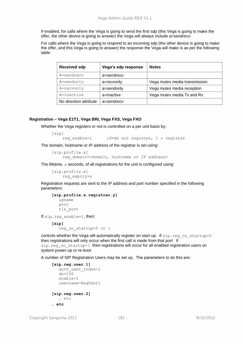
Vega Admin Guide R8.8 V1.1
Copyright Sangoma 2012 - 281 - 8/10/2012
If enabled, for calls where the Vega is going to send the first sdp (this Vega is going to make the offer, the other device is going to answer) the Vega will always include a=sendrecv.
For calls where the Vega is going to respond to an incoming sdp (the other device is going to make the offer, and this Vega is going to answer) the response the Vega will make is as per the following table:
Received sdp Vega‟s sdp response Notes
A=sendrecv a=sendrecv
A=sendonly a=recvonly Vega mutes media transmission
A=recvonly a=sendonly Vega mutes media reception
A=inactive a=inactive Vega mutes media Tx and Rx
No direction attribute a=sendrecv
Registration – Vega E1T1, Vega BRI, Vega FXS, Vega FXO
Whether the Vega registers or not is controlled on a per unit basis by:
[sip]
reg_enable=1 ;0=do not register, 1 = register
The domain, hostname or IP address of the registrar is set using:
[sip.profile.x]
reg_domain=<domain, hostname or IP address>
The lifetime, s seconds, of all registrations for the unit is configured using:
[sip.profile.x]
reg_expiry=s
Registration requests are sent to the IP address and port number specified in the following parameters:
[sip.profile.x.registrar.y]
ipname
port
tls_port
If sip.reg_enable=1, then:
[sip]
reg_on_startup=0 or 1
controls whether the Vega will automatically register on start-up. If sip.reg_on_startup=0
then registrations will only occur when the first call is made from that port. If sip.reg_on_startup=1 then registrations will occur for all enabled registration users on
system power-up or re-boot.
A number of SIP Registration Users may be set up. The parameters to do this are:
[sip.reg.user.1]
auth_user_index=1
dn=100
enable=1
username=RegUser1
[sip.reg.user.2]
… etc
… etc

Vega Admin Guide R8.8 V1.1
Copyright Sangoma 2012 - 282 - 8/10/2012
The Vega will register with each sip.reg.user.x that is enabled. username forms the central
part of the username used for registration. Dn provides the telephone number part of the contact
information, i.e. dn@ip_address_of_vega.
If the registration server is going to request authentication, then configure auth_user_index to
point to the sip.auth.user.n info that should be used to respond to the authentication
challenge.
1. Vega gateways support the ability to use more than 1
registrar for redundancy and for load balancing purposes. Either multiple alternative Registrars can be defined through use of a list of Registrars, or multiple alternative Registrars can be defined through use of DNS SRV records on a single DNS SRV name. This operates exactly the same way that Multiple SIP proxies do – see section 16.4.1.1 “Multiple SIP Proxy Support” for details.
2. Vega gateways can register with multiple proxies simultaneously (one per sip profile). For more details see Using_multiple registrations_on_R8_x_01 on the technical documents page of www.wiki.sangoma.com/vega
For more details on the structure of registration and other SIP messages, see IN_10- Introduction to Vega SIP mesaging. Also see the „SIP REGISTRATON and SIP INVITE configuration‟ utility on the www.wiki.sangoma.com/vega (Documentation > Step by step configuration).
NOTE

Vega Admin Guide R8.8 V1.1
Copyright Sangoma 2012 - 283 - 8/10/2012
SIP Authentication
Vega gateways may be configured to respond appropriately to authentication challenges (e.g. to REGISTRATION, INVITE, ACK and BYE messages).
Vega gateways support the ability to define one or more authentication username and password combinations to respond to the authentication challenges. The parameters used are:
[sip.auth.user.1]
enable=1
username=authuser1
password=pass1
srce=IF:01
[sip.auth.user.2]
enable=1
username=authuser2
password=pass2
srce=IF:02,TEL:0123.*
The username used in the response to the authentication challenge is sip.auth.user.n.username
The username / password combination defined for a user is valid for calls whose telephony details
match the srce specification. srce can contain the IF: and TEL: tokens to match against the call
details. For telephony to LAN calls, srce is matched against the incoming call details, for LAN to
telephony, srce is matched against the call details used for making the telephony call (i.e. the
destination call details).
1. srce may only use Dial Plan srce wildcards, e.g. . * ? [xyz]
– it may not use destination wildcards like <1> as this will not be defined.
2. If the case where different users‟ srce expressions
overlap, the Vega will just use the username / password in the first found user that matches.
Incoming INVITEs
[sip]
accept_non_proxy_invites=0 or 1
controls whether the Vega will accept INVITES from sources other than the configured default_proxy (and backup proxies).
Local and Remote Rx Ports
The default UDP port number used for SIP signalling is 5060. Sometimes, however, use of a different port number may be desired.
[sip]
local_rx_port=1 to 65535 ;default=5060
sets the UDP port on which the gateway expects to receive SIP messages. If the value is non-5060 then the gateway will listen on both ports 5060 and the one specified by
sip.local_rx_port.
[sip]
remote_rx_port=1 to 65535 ;default=5060
NOTE

Vega Admin Guide R8.8 V1.1
Copyright Sangoma 2012 - 284 - 8/10/2012
sets the UDP port to which the gateway should send SIP messages.
PRACK Support
Allows configuration of the gateway to send PRACKs (Provisional ACKnowledgements). By default this is “off” but you can set it to “supported” or “required”:
[sip]
prack=supported
Permitted values:
off – PRACK not supported at all
supported – the gateway will use PRACK if the remote proxy or gateway requires it
required – the gateway will insist that the remote proxy or gateway uses PRACK
otherwise the connection will not proceed
REFER/REPLACES
All Vega gateways will respond to the REFER / REPLACES method for transferring calls, but only FXS gateways can initiate call transfers (initiated using hookflash – if supplementary services is enabled)
7.
On receiving a REFER, the Vega will send an INVITE (with the replaces header) to the destination specified in the REFER. If the INVITE resulting from the REFER should be sent via the SIP proxy, set:
[_advanced.sip]
refer_invite_to_proxy=1
RPID – Remote Party ID header
SIP Vegas support the generation and reception of the SIP RPID (Remote Party ID) header in INVITE messages.
RPID headers provide the SIP recipient with details of the calling party and the original called number or the (last) redirecting number.
To enable the generation and reception of RPID headers, set:
[_advanced.sip.privacy]
standard=rpid ; default=rfc3323
16.4.1.5 Mapping ISDN SETUP Information Elements to SIP RPID header parameters
Four cases are illustrated to demonstrate the methodology used in translating the paramterters
Case 1 – Calling number presentation allowed
ISDN SETUP8 SIP INVITE
Called party number IE>number digits Request-URI & user part of To:
Calling party number IE>number digits User part of From:
Calling party number IE>presentation (allowed) not explicitly forwarded
Display IE Name part of From:
7 See the „FXS Call Transfer‟ documnt for more details on configuring FXS ports to initiate call
transfers.
8 IE stands for Information Element; a message element in ISDN signalling

Vega Admin Guide R8.8 V1.1
Copyright Sangoma 2012 - 285 - 8/10/2012
Case 2 – Calling number presentation allowed with original called number or redirection IE
ISDN SETUP SIP INVITE
Called party number IE>number digits Request-URI & user part of To:
Calling party number IE>number digits User part of From:
Calling party number IE>presentation (allowed) not explicitly forwarded
Display IE Name part of From:
Original called number / redirection IE RPID>party=redirect
Original called number / redirection IE>number digits RPID>user=
Original called number / redirection IE>screening indicator
RPID>screen=
Original called number / redirection IE>Presentation RPID>privacy=
RPID header format:
Remote-Party-ID: “rpid_disp_name” <sip:rpid_CgPN@domain;user=phone>;rpid_options
e.g.:
Remote-Party-ID: “John Smith” <sip: [email protected];user=phone>;screen=yes;party=calling
Case 3 – Calling number presentation restricted
ISDN SETUP SIP INVITE
Called party number IE>number digits Request-URI & user part of To:
User part of From: = “restricted user”
Name part of From: = “restricted name”
Calling party number IE RPID>party=calling
Calling party number IE>number digits RPID>user=
Calling party number IE>Screening indicator RPID>screen=
Calling party number IE>presentation (restricted) RPID>privacy=full
Display IE RPID>display-name
Case 4 – Calling number presentation restricted with original called number or redirection IE
ISDN SETUP SIP INVITE
Called party number IE>number digits Request-URI & user part of To:
User part of From: = “restricted user”
Name part of From: = “restricted name”
Calling party number IE RPID>party=calling
Calling party number IE>number digits RPID>user=
Calling party number IE>screening indicator RPID>screen=
Calling party number IE>presentation (restricted) RPID>privacy=full
Display IE RPID>display-name
Original called number / redirection IE RPID>party=redirect
Original called number / redirection IE>number digits RPID>user=
Original called number / redirection IE>screening indicator
RPID>screen=
Original called number / redirection IE>presentation RPID>privacy=

Vega Admin Guide R8.8 V1.1
Copyright Sangoma 2012 - 286 - 8/10/2012
16.4.1.6 Mapping SIP RPID header parameters to ISDN SETUP Information Elements
Three cases are illustrated to demonstrate the methodology used in translating the paramterters
Case 1 – No RPID headers
SIP INVITE ISDN SETUP
Request-URI Called party number IE>number digits
User part of From: Calling party number IE>number digits
Name part of From: Display IE
Case 2 – with calling RPID header
SIP INVITE ISDN SETUP
Request-URI Called party number IE >number digits
RPID>party=calling Calling party number IE
RPID>user= Calling party number IE>number digits
RPID>screen= Calling party number IE>screening indicator
RPID>privacy= Calling party number IE>presentation
RPID>display-name Display IE
Case 3 – with calling and redirect RPID headers
SIP INVITE ISDN SETUP
Request-URI Called party number IE>number digits
RPID>party=calling Calling party number IE
RPID>user= Calling party number IE>number digits
RPID>screen= Calling party number IE>screening indicator
RPID>privacy= Calling party number IE>presentation
RPID>display-name Display IE
RPID>party=redirect Original called number / redirection IE
RPID>user= Original called number / redirection IE>number digits
RPID>screen= Original called number / redirection IE>screening indicator
RPID>privacy= Original called number / redirection IE>presentation
16.4.1.7 ISDN screening indicator to SIP screen Mappings
Screening indicator RPID>screen
User provided, not screened screen=no
User provided, verified and passed screen=yes
User provided, verified and failed screen=no
Network provided screen=no
16.4.1.8 SIP screen to ISDN screening indicator Mappings
RPID>screen Screening indicator
Screen=no User provided, not screened
Screen=yes User provided, verified and passed

Vega Admin Guide R8.8 V1.1
Copyright Sangoma 2012 - 287 - 8/10/2012
16.4.1.9 Mappings between ISDN presentation indicator and SIP privacy
Presentation indicator RPID>privacy
Allowed privacy=off
Restricted privacy=on
RFC 3323 Privacy header and RFC 3325 extensions
SIP Vega gateways support the generation and reception of the Privacy header in INVITE and REGISTER messages, as defined in RFC 3323, and also the P-Asserted-Identity and P-Preferred-Identity headers defined in RFC3325.
The Privacy: header provides details about how the details relating to the calling party should be handled.
To enable the generation and reception of the Privacy: header, set:
[_advanced.sip.privacy]
standard=rfc3323 ; default=rfc3323
The Privacy: header can include one or more of the following values:
header9
session10
user
none
id11
optionally followed by
;critical
Note that if multiple types of privacy are required, all privacy types MUST be included in the Privacy header field value.
header: Request that privacy services modify headers that cannot be set arbitrarily by the user (Contact/Via). The user requests that those headers which might reveal information about the user be obscured. Also, that no unnecessary headers should be added by the service that might reveal personal information about the originator of the request.
session: Request that privacy services provide privacy for session media. The user requests that a privacy service provide anonymisation for the session(s) initiated by this message. This will mask the IP address from which the session traffic would ordinarily appear to originate. When session privacy is requested, user agents MUST NOT encrypt SDP bodies in messages.
user: Request that privacy services provide a user-level privacy function. This privacy level is usually set only by intermediaries, in order to communicate that user level privacy functions must be provided by the network, presumably because the user agent is unable to provide them. User agents MAY however set this privacy level for REGISTER requests, but SHOULD NOT set 'user' level privacy for other requests. Any non-essential information headers are to be removed and changes to From: and Call-ID: headers to make them anonymous is to be performed.
9 Not currently supported by the Vega
10 Not currently supported by the Vega
11 id is an extension to RFC3323 defined in RFC 3325

Vega Admin Guide R8.8 V1.1
Copyright Sangoma 2012 - 288 - 8/10/2012
none: Privacy services must not perform any privacy function. The user requests that a privacy service apply no privacy functions to this message, regardless of any pre-provisioned profile for the user or default behavior of the service. User agents can specify this option when they are forced to route a message through a privacy service which will, if no Privacy header is present, apply some privacy functions which the user does not desire for this message.
id: Privacy requsted for Third-Party Asserted Identity. The user requests that the Network
Asserted Identity to be kept private with respect to SIP entities outside the Trust Domain with which the user is authenticated.
critical: Privacy service must perform the specified services or fail the request. The user asserts
that the privacy services requested for this message are critical, and that therefore, if these privacy services cannot be provided by the network, this request should be rejected.
The extensions of RFC3325 add P-Asserted-Identity and P-Preferred_Identity.
P-Asserted-Identity: This is used between Trusted SIP entities; it carries the identity of the user sending the SIP message as verified by authentication. There may be one or two P-Asserted-Identity values. If there is one value, it MUST be a sip, sips, or tel URI. If there are two values, one value MUST be a sip or sips URI and the other MUST be a tel URI. (Note: proxies can (and will) add and remove this header field.)
P-Preferred_Identity: This is used between a user agent and a Trusted Proxy; it carries the
identity that the user sending the SIP message wishes to be used as the P-Asserted-Header that the Trusted Proxy will insert. There may be one or two P-Preferred-Identity values. If there is one value, it MUST be a sip, sips, or tel URI. If there are two values, one value MUST be a sip or sips URI and the other MUST be a tel URI. (Note: proxies can (and will) add and remove this header field.)
16.4.1.10 ISDN to SIP
ISDN Presentation Indicator to SIP Privacy Header mapping:
ISDN Presentation Indicator SIP Privacy Header Content
Allowed Privacy: none
Restricted Privacy: id
Number not available Privacy: id
ISDN screening indicator to SIP P-Asserted-Identity / P-Preferred-Identity mapping
ISDN Screening Indicator SIP Header
Not screened P-Preferred-Identity
Passed P-Asserted-Identity
Failed P-Preferred-Identity
Network P-Asserted-Identity
e.g. Preferred Identity:
Privacy: id
P-Preferred-Identity: "Alice" <sip:[email protected]>
e.g. Asserted Identity: P-Asserted-Identity: "Alice" <sip:[email protected]>
P-Asserted-Identity: tel:+441344784917
Privacy: id

Vega Admin Guide R8.8 V1.1
Copyright Sangoma 2012 - 289 - 8/10/2012
16.4.1.11 SIP to ISDN
SIP Privacy Header to ISDN Presentation Indicator mapping:
SIP Privacy Header Content ISDN Presentation Indicator
Privacy: user Restricted
Privacy: none Allowed
Privacy: id Restricted
SIP P-Asserted-Identity / P-Preferred-Identity to ISDN screening indicator mapping
SIP Header ISDN Screening Indicator
P-Asserted-Identity Network
P-Preferred-Identity Not screened
Session Timers
In order that SIP gateways can ensure calls are cleared down even if they never receive a BYE message, session timers can be enabled. These are defined with the following parameters:
[sip]
sess_timer_index=1
[sip.sess_timer.n]
enable=0
interval=1800
min_interval=300
refresher_pref=remote
sess_timer_index chooses the appropriate [sip.sess_timer.n] (n=1 to 3) set of
parameters to use. If enable=1 the Vega will act upon / generate session timer fields.
If the Vega initiates the SIP call it sends out an INVITE with the session timer value set to interval,
and the refresher parameter set to UAS or UAC depending on whether refresher_pref is set to
remote or local (respectively). If refresher_pref is set to local then the Vega will initiate the session timer checks. If a 422 response is received, the Vega will accept the higher requested session timer value.
If the Vega receives a call with the session timer value set, provided that the time is greater than min_interval then the Vega will accept the session timer value. It will accept the requested UAC / UAS setting of the refresher parameter in the SIP message (initiating session timer checks if the setting is UAS).
If the session time value received is smaller than min_interval then the Vega will send out a 422
with the requested time set to min_interval.
If the Vega is generating the session timer checks, after about half the negotiated session timer timeout value (the session timer value both ends agree), the Vega will send out REINVITE
12.
12 Providing that there is enough time to do send out the REINVITE. To ensure the REINVITE is
sent, make sure that min_interval >= 480ms.

Vega Admin Guide R8.8 V1.1
Copyright Sangoma 2012 - 290 - 8/10/2012
If it receives a „200 OK‟ it re-starts the timer, if it does not receive the „200 OK‟ after half the time to the timeout it sends another REINVITE. If no „200 OK‟ response is received by the time the negotiated session timer timeout expires the call is cleared (a BYE is sent).
If the Vega is receiving the session timer checks, it too will count down the negotiated (agreed) session timer timeout. If a REINVITE is received it will re-start the counter. If the countdown expires then it will clear the call and send a BYE.
For more details on the Session Timers see RFC 4028.
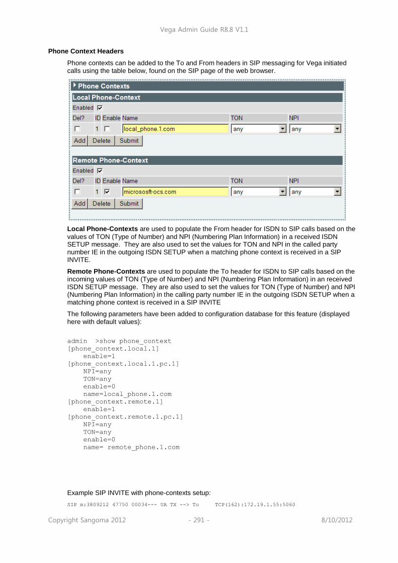
Vega Admin Guide R8.8 V1.1
Copyright Sangoma 2012 - 291 - 8/10/2012
Phone Context Headers
Phone contexts can be added to the To and From headers in SIP messaging for Vega initiated calls using the table below, found on the SIP page of the web browser.
Local Phone-Contexts are used to populate the From header for ISDN to SIP calls based on the
values of TON (Type of Number) and NPI (Numbering Plan Information) in a received ISDN SETUP message. They are also used to set the values for TON and NPI in the called party number IE in the outgoing ISDN SETUP when a matching phone context is received in a SIP INVITE.
Remote Phone-Contexts are used to populate the To header for ISDN to SIP calls based on the incoming values of TON (Type of Number) and NPI (Numbering Plan Information) in an received ISDN SETUP message. They are also used to set the values for TON (Type of Number) and NPI (Numbering Plan Information) in the calling party number IE in the outgoing ISDN SETUP when a matching phone context is received in a SIP INVITE
The following parameters have been added to configuration database for this feature (displayed here with default values):
admin >show phone_context
[phone_context.local.1]
enable=1
[phone_context.local.1.pc.1]
NPI=any
TON=any
enable=0
name=local_phone.1.com
[phone_context.remote.1]
enable=1
[phone_context.remote.1.pc.1]
NPI=any
TON=any
enable=0
name= remote_phone.1.com
Example SIP INVITE with phone-contexts setup: SIP m:3809212 47750 00034--- UA TX --> To TCP(162):172.19.1.55:5060

Vega Admin Guide R8.8 V1.1
Copyright Sangoma 2012 - 292 - 8/10/2012
INVITE sip:1234;[email protected]:5060;user=phone SIP/2.0 Via: SIP/2.0/TCP 172.19.1.67:5060;branch=z9hG4bK-vega1-000A-0001-0004-CB9A50C9 From: "0" <sip:0;[email protected]>;tag=007D-0006-DBDE6A28 To: <sip:1234;[email protected]> Max-Forwards: 70 Call-ID: 0078-0004-63929283-0@91AD727D0597C801D CSeq: 1523683 INVITE Contact: <sip:0;[email protected]:5060;transport=tcp> Supported: replaces, privacy Allow: INVITE,ACK,BYE,CANCEL,INFO,NOTIFY,OPTIONS,REFER,UPDATE
Accept-Language: en Content-Type: application/sdp Privacy: none P-Preferred-Identity: "0" <sip:0;[email protected]> User-Agent: VEGA400/10.02.08.2xS028 Content-Length: 294 v=0 o=Vega 134 134 IN IP4 172.19.1.67 s=Sip Call c=IN IP4 172.19.1.67 t=0 0 m=audio 10008 RTP/AVP 18 0 8 4 101
a=rtpmap:18 G729/8000 a=rtpmap:0 PCMU/8000 a=rtpmap:8 PCMA/8000 a=rtpmap:4 G723/8000 a=rtpmap:101 telephone-event/8000 a=fmtp:101 0-15,16 a=fmtp:18 annexb=no a=sendrecv
Vega Admin Guide R8.8 V1.1
Copyright Sangoma 2012 - 293 - 8/10/2012
User Defined String in SIP To / From Headers
User defined strings can be added to the SIP To and From and To headers sent by the Vega. A typical use of this parameter is to add the “user=phone” parameter to SIP INVITEs sent by the Vega. Parameter:
_advanced.sip.from_header_uri_params
Possible values: NULL – Default – Don‟t include any string Any string between 1 and 39 characters in length
Parameter:
_advanced.sip.to_header_uri_params
Possible values: NULL – Default – Don‟t include any string
Any string between 1 and 39 characters in length
For example, if from_header_uri_params=”user=phone”, a SIP INVITE would be similar to
this: SIP m:0626532 626532 00001--- UA TX --> To TCP(72):172.19.1.55:5060
INVITE sip:[email protected]:5060;user=phone SIP/2.0
Via: SIP/2.0/TCP 172.19.1.67:5060;branch=z9hG4bK-vega1-000A-0001-0000-8C21B472
From: "0" <sip:[email protected];user=phone>;tag=007E-0000-CB58C2DC
To: <sip:[email protected];user=phone>
Max-Forwards: 70
Call-ID: 0078-0000-61F25547-0@91AD727D0597C801D
CSeq: 250611 INVITE
Contact: <sip:[email protected]:5060;transport=tcp>
Supported: replaces, privacy
Allow: INVITE,ACK,BYE,CANCEL,INFO,NOTIFY,OPTIONS,REFER,UPDATE
Accept-Language: en
Content-Type: application/sdp
Content-Length: 294
16.5 SIP Trunking
In general a “SIP trunk” is a grouping together of a number of SIP calls on a point to point basis from a device to an ITSP (Internet Telephony Service Provider). Typically the device will register only once and then multiple calls can be carried under that registration. In some other cases authentication is carried out by examining the originating IP address and checking that this is in the permissible range.
When purchasing a SIP trunk from a provider the following pieces of information will typically be supplied by the service provider:
Username and password
Telephone numbers to be used on the service
IP address of ITSP
The username and password will be configured in the Vega on the VoIP tab of quick config. Alternatively if using expert config this information will be used in the authentication and registration users sections.
The telephone numbers provided will be used in the dial plans of the Vega to route the calls to the correct interface.
The IP address of the ITSP will be used to populate the Proxy and Registrar address fields on the VoIP tab of quick config or the SIP proxy and registrar settings on the SIP profile page of expert config.

Vega Admin Guide R8.8 V1.1
Copyright Sangoma 2012 - 294 - 8/10/2012
For a more detailed explanation of how to configure SIP trunks please see the document on SIP trunking available on www.wiki.sangoma.com/vega.
16.6 RFC2833
RFC2833 is a standard for transmitting and receiving DTMF signals and hookflash as part of the real-time media stream.
For DTMF/hookflash to be sent as RFC2833 messages, firstly ensure that “Out Of Band DTMF” is configured True against the appropriate codec.
RFC2833 Configuration
[sip]
dtmf_transport=rfc2833 ; use rfc2833 to send out-of-band DTMF (to use info
messages, set dtmf_transport=info; to transit both RFC2833 and info messages, and to act upon received RFC2833 messages, set dtmf_transport=rfc2833_txinfo)
rfc2833_payload=96 ; Configures the payload field in RTP messages for
RFC2833 data. RFC2833 data is sent in its own UDP/IP packets (it is not combined with the audio).
[_advanced.rfc2833]
one_shot=0/1 ; In rfc2833 messages DTMF tone duration may or may
not be retained: 0 = true duration played, 1 = single fixed length DTMF tone pulses played (on-time is defined by _advanced.dsp.dtmf_cadence_on_time, off time defined by _advanced.dsp.dtmf_cadence_off_time)
audio_with_DTMF=0/1 ; 0 = no audio packets are sent when RFC2833 tone
packets are sent; 1 = send both audio packets and RFC2833 tone packets when tone present
tx_volume=0 to 127 ; Power level of tone reported in Tx RFC2833 packets = -
n dBm0 (e.g. 10 => -10dBm0). RFC2833 says tones with a power 0 to -36dBm0 must be accepted, and below -55dBm0 must be rejected.

Vega Admin Guide R8.8 V1.1
Copyright Sangoma 2012 - 295 - 8/10/2012
16.7 Executive Interrupt
Vega gateways support Resource-Priority Headers for Preemption Events, as defined by RFC 4411 & RFC 4412.
This is a method by which calls from higher priority callers, rather than receiving a busy response when making a call to a phone already engaged on a phone call, will „bump‟ the other party in the conversation and will be connected directly to the called party. This feature is sometimes known as „Executive Intrusion‟, „Boss / Secretary‟ working, Call Barge, MLPP or Multi-Level Precedence and Preemption.
If enabled, INVITES are sent out with Resource-Priority header values; also received INVITES containing a Resource-Priorty header will not necessarily be rejected with busy, but will „bump‟ the existing call if its Resource-Priority is higher than the Resource-Priority of the call in progress.
Call with precedence Y < = precedence X
A B C
INVITE
Resource-Priority: NameSpace.X
Etc.
INVITE
Resource-Priority: NameSpace.Y
Busy here
Call with precedence Y > precedence X
A B C
INVITE
Resource-Priority: NameSpace.X
Etc.
INVITE
Resource-Priority: NameSpace.Y
BYE
Reason: pre-emption ;cause=1 ;text=”UA Preemption”
Etc.
If a call gets „bumped‟ the BYE for that call will contain a Reason header containing “cause=1 ;text=”UA Preemption”.

Vega Admin Guide R8.8 V1.1
Copyright Sangoma 2012 - 296 - 8/10/2012
Configuring NameSpace for Resource-Priority Headers
A NameSpace defines a set of named priority values used in Resource-Priority headers. It is a priority ordered list of priority names. Three standard NameSpace definitions are pre-configured in the Vega: dsn, drsn and q735. Additional user defined NamesSpace definitions may be set up.
At any time the Vega only uses a single NameSpace definition to generate Resource-Priorities in outgoing SIP calls and to act upon received Resource-Priorities in incoming SIP calls.
The NameSpace definition to use is configured in the Selected Namespace option.
If a call is received for a NameSpace other than that configured, the Vega will treat the call as though it were a standard call with no Resource-Priority header.
Namespace definitions are priority ordered lists of names or IDs of priorities, listed in increasing priority order.
e.g. dsn: lowest priority = routine highest priority = flash-override.
Selecting modify in the user defined list allows the NamSpace Name and Priority values (IDs) to be configured.

Vega Admin Guide R8.8 V1.1
Copyright Sangoma 2012 - 297 - 8/10/2012
Resource-Priority for SIP calls initiated by Vega gateways
The Resource-Priority to use for outbound SIP calls is defined in the SIP authentication configuration section.
A single Resource-Priority may be configured for each SIP Authentication User. (The subscriber field defines which telephony port(s) the SIP Authentication User represents.)
The resource priority is configured through the selection of an entry in a pull down box. The values contained in the pull down box are the values defined in the NameSpace configuration (see section 0 ”Configuring NameSpace for ”).
The value selected will be the value sent out as the Resource-Priority with every SIP call made by that user.
Ensure that the SIP Authentication User is enabled, otherwise Resource-Priority handling will not be activated.
NOTE
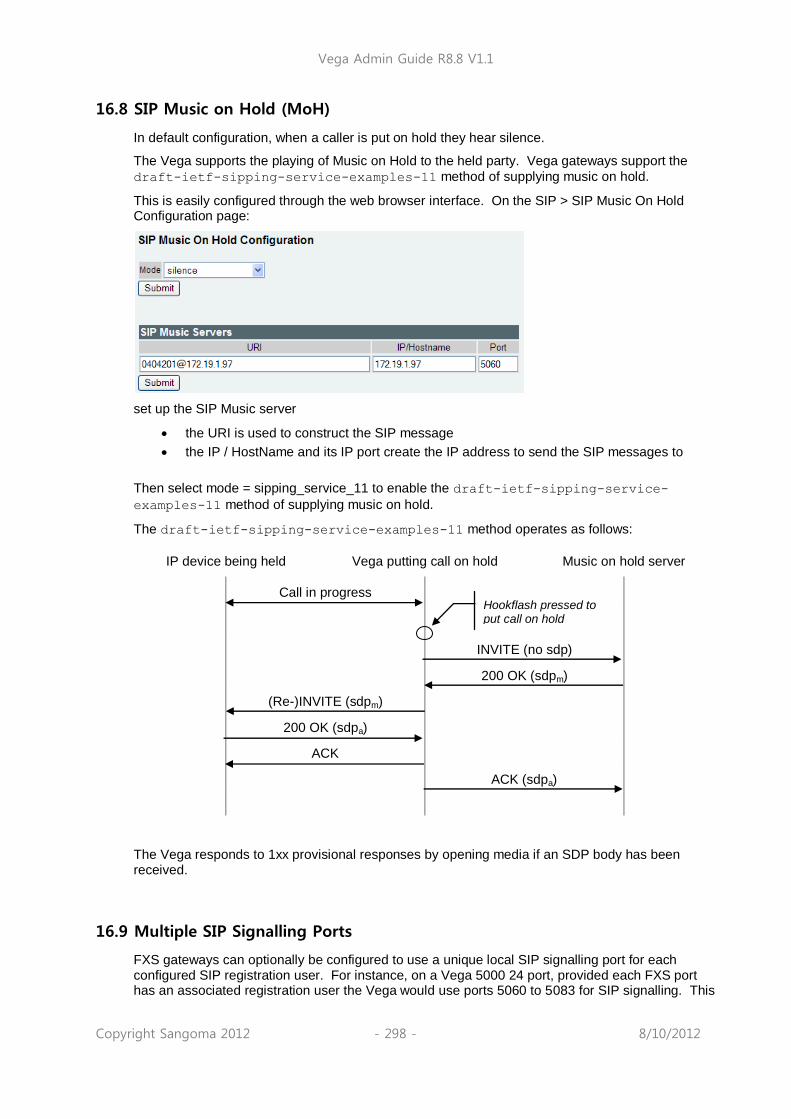
Vega Admin Guide R8.8 V1.1
Copyright Sangoma 2012 - 298 - 8/10/2012
16.8 SIP Music on Hold (MoH)
In default configuration, when a caller is put on hold they hear silence.
The Vega supports the playing of Music on Hold to the held party. Vega gateways support the
draft-ietf-sipping-service-examples-11 method of supplying music on hold.
This is easily configured through the web browser interface. On the SIP > SIP Music On Hold Configuration page:
set up the SIP Music server
the URI is used to construct the SIP message
the IP / HostName and its IP port create the IP address to send the SIP messages to
Then select mode = sipping_service_11 to enable the draft-ietf-sipping-service-
examples-11 method of supplying music on hold.
The draft-ietf-sipping-service-examples-11 method operates as follows:
IP device being held Vega putting call on hold Music on hold server
Call in progress
INVITE (no sdp)
200 OK (sdpm)
(Re-)INVITE (sdpm)
200 OK (sdpa)
ACK
ACK (sdpa)
The Vega responds to 1xx provisional responses by opening media if an SDP body has been received.
16.9 Multiple SIP Signalling Ports
FXS gateways can optionally be configured to use a unique local SIP signalling port for each configured SIP registration user. For instance, on a Vega 5000 24 port, provided each FXS port has an associated registration user the Vega would use ports 5060 to 5083 for SIP signalling. This
Hookflash pressed to put call on hold

Vega Admin Guide R8.8 V1.1
Copyright Sangoma 2012 - 299 - 8/10/2012
can be particularly useful when working with a SIP proxy or softswitch that doesn‟t expect multiple SIP UA‟s to be present behind a single IP address. i.e. Cisco Call Manager (CCM)
Parameter: _advanced.sip.cisco_cm_compatibility
Possible Values: 0 – Default – Do not use multiple SIP ports
1 – Use a distinct SIP port for each registration user
WARNING!
If this feature is enabled the local signalling port for TLS must be set so that it‟s outside the range that will be used for multiple port signalling. The parameter that controls the TLS port is sip.tls.local_rx_port.
16.10 TDM Channel Information
TDM (ISDN / POTS) B channel and interface information can be advertised in SIP messages using 'P-Access-Network-Info' headers. In the case where a call originates from the Vega the header is included in the original SIP request message (INVITE). In the case where the Vega terminates the call the header is included in the ringing indication message (typically 180 or 183) or if not present in the 200 OK (connect) message. Parameter: _advanced.sip.access_network_info.enable
Possible values: 0 – Default - Do not include the P-Access-Network-Info header
1 - Include the P-Access-Network-Info header
Sample SIP message header: SIP m:0332867 18540 00124--- UA TX --> To UDP(3):172.19.1.58:5060
INVITE sip: [email protected]:5060 SIP/2.0
Via: SIP/2.0/UDP 172.19.1.81:5060;rport;branch=z9hG4bK-vega1-000A-0001-0012
From: "unknown" <sip: [email protected]>;tag=007D-0015
To: <sip: [email protected]>
Max-Forwards: 70
Call-ID: 0078-000E-66ACE409-00000000@D02C806FC093603C6
CSeq: 133147 INVITE
P-Access-Network-Info: X-VEGA-NET;x-if0401;x-port0000;x-chan0001
Contact: <sip: [email protected]:5060>
Supported: replaces, privacy
Allow: INVITE,ACK,BYE,CANCEL,INFO,NOTIFY,OPTIONS,REFER,UPDATE
Accept-Language: en
Content-Type: application/sdp
Content-Length: 294
In the example message header above the incoming ISDN call was placed using interface 0401 on bearer channel 1.

Vega Admin Guide R8.8 V1.1
Copyright Sangoma 2012 - 300 - 8/10/2012
16.11 SIP Status codes
1xx - SIP Provisional Responses Supported
The Vega responds to 1xx provisional responses by opening media if an SDP body has been received.
1xx responses generated by the Vega are:
100 Trying - The Vega received an INVITE request and is processing it.
180 Ringing - The destination of the call is ringing.
181 Call is being forwarded
183 Session Progress - The call has not yet been answered but media is available.
Other 18x messages, like 182 Queued are accepted.
2xx - SIP Success Codes Supported
The Vega supports both 200 and 202 messages:
200 OK
202 Accepted - The Vega has accepted a transfer request and will generate an INVITE to the transfer target.
3xx - SIP Redirection Codes Supported (Responded To)
The Vega responds to 3xx responses by trying to initiate another call if alternative "contacts" are provided, otherwise the call is terminated.
300 Multiple Choices
301 Moved Permanently
302 Moved Temporarilly
305 Use Proxy
380 Alternative Service
4xx - SIP Request Failure Codes Supported
With the exception of "401 Unauthorised", "407 Proxy Authentication Required", "415 Unsupported Media Type" and “491 Request Pending”, 4xx responses result in termination of the call.
4xx responses generated by the Vega are13
:
400 Bad Request - Missing Call-ID field; the Vega received a request with a "Call-ID" field that was missing or invalid.
400 Bad Request - Missing To field; the Vega received a request with a "To" field that was missing or invalid.
400 Bad Request - Missing From field; the Vega received a request with a "From" field that was missing or invalid.
401 Unauthorised (retry Register) - The Vega attempts to resend the INVITE with the authentication response
[402 Payment Required]
[403 Forbidden]
13 Items in square brackets are not generated by the Vega, but will be handled by the Vega.

Vega Admin Guide R8.8 V1.1
Copyright Sangoma 2012 - 301 - 8/10/2012
404 Not Found - The Vega could not find a route for the destination (sometimes caused by dial plan errors).
405 Method Not Allowed - The Vega received a request that it knows about but does not allow. e.g. when a PRACK request is received when sip.PRACK=off
406 Not Acceptable - The Vega received an INVITE with an illegal SDP.
407 Proxy Authentication Required - The Vega tries to resend the INVITE with the authentication response
14[408 Request Timeout - The server could not produce a response within a
suitable amount of time, for example, if it could not determine the location of the user in time.]
409 Conflict
410 Gone
411 Length Required
413 Request Entity Too Large - the content length of a request must not exceed 1500 bytes.
414 Request-URI Too Long - The request-URI must not exceed 100 characters
415 Unsupported Media Type - The request received by the Vega has a message body which is in an unsupported format. (Note: not necessarily a media problem)
420 Bad Extension - The Vega did not understand the protocol extension specified in a "Proxy-Require" or "Require" header.
422 Session Interval Too Small - The Session Interval requestsed is lower than the min_interval configured in the Vega
480 Temporarily Unavailable - The Vega received a cause 18 (no user responding) disconnection on its telephony interface.
481 Call Leg/Transaction Does Not Exist - The Vega received a request for which a matching call leg and/or transaction was not found.
482 Loop Detected
483 Too Many Hops
484 Address Incomplete
485 Ambiguous
486 Busy Here - The destination of the call is busy.
487 Request Terminated - An INVITE request has been cancelled.
488 Not Acceptable Here - An INVITE was received for which no media is supported. (i.e. expect Codec mismatch.) This will be accompanied with a "304 No matching media" warning.
491 Request Pending - If the Call ID does not relate to this Vega, a REINVITE is sent immediately. Otherwise, the Vega waits for the other party to send a REINVITE
14 408 is not generated by the Vega, but it will accept and handle it

Vega Admin Guide R8.8 V1.1
Copyright Sangoma 2012 - 302 - 8/10/2012
5xx - SIP Server Failure Codes Supported
The Vega responds to 5xx responses by terminating the call.
5xx responses generated by the Vega are:
500 Server Internal Error - No Call Legs Left; there are no more SIP resources available
500 Server Internal Error - Still Processing Old Invite; an INVITE was received while an earlier INVITE was still being processed.
500 Server Internal Error - Destination Out Of Order; the Vega received a cause 27 (destination out of order) on its telephony interface.
500 Server Internal Error - Temporary Failure; the Vega received a cause 41 (Temporary failure) on its telephony interface.
500 Server Internal Error - No Channel Available; the Vega received a cause 34 (no circuit/channel available) on its telephony interface.
500 Server Internal Error - Requested Channel Not Available; the Vega received a cause 44 (Requested circuit/channel not available) on its telephony interface.
501 Not Implemented - The Vega received a SIP request with a method it does not recognise.
502 Bad Gateway
503 Service Unavailable - Includes Vega Congested.
504 Server Time-out
505 Version Not Supported - The Vega received a SIP request with a version other than "SIP2.0".
513 Message Too Large
6xx - SIP Global Failure Codes Supported (Generated and Responded To)
The Vega responds to 6xx responses by terminating the call.
6xx responses generated by the Vega are:
600 Busy Everywhere
603 Decline - The Vega declined the request (in response to a REFER request).
604 Does Not Exist Anywhere
606 Not Acceptable - If the Vega had previously sent a T.38 Fax INVITE, it will try again with a G.711 INVITE
16.12 Short Form SIP Headers
Vega gateways can now optionally use short form SIP headers as per the sample message below:
SIP m:0258085 258085 00001--- UA TX --> To UDP(20):172.19.1.65:5060
INVITE sip:[email protected]:5060 SIP/2.0
v: SIP/2.0/UDP 172.19.1.97:5060;rport;branch=z9hG4bK-vega1-000A-0001-
0001-
B19B6DC0
f: "201" <sip:[email protected]>;tag=007D-0002-59944BA0
t: <sip:[email protected]>
Max-Forwards: 70
i: 0078-0002-322EC79E-0@B9FB2DA478699F6DD

Vega Admin Guide R8.8 V1.1
Copyright Sangoma 2012 - 303 - 8/10/2012
CSeq: 103233 INVITE
m: <sip:[email protected]:5060>
Supported: replaces, privacy
Allow: INVITE,ACK,BYE,CANCEL,INFO,NOTIFY,OPTIONS,REFER,UPDATE
Accept-Language: en
c: application/sdp
Privacy: none
P-Preferred-Identity: "201" <sip:[email protected]>
User-Agent: VEGA400/10.02.08.2xS003
The following parameter controls this behaviour: _advanced.sip.sip_headers_form
Possible values:
short – use short form SIP headers
long – Default – Use long SIP headers

Vega Admin Guide R8.8 V1.1
Copyright Sangoma 2012 - 304 - 8/10/2012
17 ENP - ENHANCED NETWORK PROXY
ENP (Enhanced Network Proxy) is a license enabled feature (i.e. requires a special license key to be applied to the product). Please contact the supplier of your product to obtain an ENP license key. ENP was previously referred to as VRP (Vega Resilient Proxy) in earlier firmware releases.
17.1 Description
The Enhanced Network Proxy feature (ENP) greatly extends the capabilities of a gateway product by including SIP proxy functionality within a single device.
ENP‟s principle functions are twofold:
To provide resilience for local SIP UA‟s in case of loss of contact with ITSP proxy.i.e. Through broadband failure, or loss of ITSP network connection.
To allow some calls that would normally always route to the ITSP to route to other devices. These can include the local gateway (hosting ENP) or other gateways or SIP devices.
17.2 ENP: Modes Of Operation
ENP can be configured to operate in three different modes (or disabled):
standalone_proxy
forward_to_itsp
itsp_trunking
off
Configuration via the Web User Interface:
Expert Config > SIP Proxy > SIP Proxy Configuration > Mode
Configuration parameter:
sipproxy.mode
Standalone Proxy Mode
In this mode the ENP behaves as a „stand alone‟ SIP Registrar and Proxy. The ENP can be used for simple registration and proxy operations, enabling SIP devices to call one another, make (or receive) calls via the gateway (for example to the PSTN or a PBX).
The ENP in standalone mode will support up to 120 attached (registered) endpoints (SIP devices). The ENP supports basic call routing and SIP transfers, but does not provide more enhanced PBX features such as Voice Mail.
Devices that wish to register to the ENP must either be defined as a SIP Proxy Auth User or have an i.p. address defined in the Trusted IP Address table.
Devices defined as SIP Proxy Auth User‟s will be challenged for authentication, whereas devices with i.p. addresses defined in the Trusted IP Address table will not be challenged for authentication (they will just register).
Additionally Trunk Gateways (TGWs) can be defined. This enables calls to be routed to (and from) TGWs without the need for the TGW‟s to register as endpoints. See further information regarding TGW‟s below.

Vega Admin Guide R8.8 V1.1
Copyright Sangoma 2012 - 305 - 8/10/2012
Forward To ITSP Mode
In this mode the ENP has one (or more) SIP ITSP Proxies defined in its configuration. All local (to the ENP) SIP devices are configured to use the ENP as their outbound proxy. All SIP messaging is sent via the ENP to the ITSP Proxy, and successful registrations are cached by the ENP.
Should the connection to the ISTP Proxy fail (the ENP continuously checks availability by sending SIP OPTIONS messages) then all local devices with cached registrations will still be able to communicate via the ENP. Once the ISTP Proxy connection is restored all SIP messaging is (once again) sent via the ENP to the ITSP.
If a call is received and routing is configured such that a particular call is destined for a TGW then the SIP messaging is forwarded to the TGW. See further information regarding TGW‟s below.
ITSP Trunking Mode
In this mode the ENP behaves similarly to the forward_to_itsp mode, however if a call is received and is destined for a locally registered endpoint (Trusted IP Address, SIP Proxy Auth User or TGW) then the SIP messaging will not be sent to the ISTP – it will be routed directly to the local endpoint destination (including TGWs).
17.3 ENP Configuration Details
17.3.1.1 ENP‟s Realm
The ENP‟s Realm should (in the case of working with an ITSP) be configured as the ITSP realm/domain (i.e. myitsp.com). In the „stand_alone‟ mode the realm could be the i.p. address of the gateway.
Configuration via the Web User Interface:
Expert Config > SIP Proxy > SIP Proxy Configuration > Realm
Configuration parameter:
sipproxy.realm
17.3.1.2 ENP‟s Rx Port
The ENP‟s Rx (receive) Port should be different to the gateway‟s Local SIP Port (configured in the gateways SIP settings). It is useful to consider the ENP as a separate device to the gateway which shares it‟s i.p. address with the gateway, but is addressed using a different i.p. port.
When the gateway is sending SIP messaging to the ENP it can address it using the local loopback address of 127.0.0.1 and the ENP‟s Rx Port.
Configuration via the Web User Interface:
Expert Config > SIP Proxy > SIP Proxy Configuration > Rx Port

Vega Admin Guide R8.8 V1.1
Copyright Sangoma 2012 - 306 - 8/10/2012
Configuration parameter:
sipproxy.rx_port
17.3.1.3 How Can I Tell Who Is Registered To The ENP?
All registered users (registered to the ENP, possibly to an ITSP too – if set to „forward_to_itsp‟ mode) can be seen in the Web User Interface:
Expert Config > SIP Proxy > SIP Proxy Configuration > SIP Proxy Registered Users
The following CLI command will also show registered users:
sipproxy show reg
17.3.1.4 SIP Proxy Auth Users
SIP Proxy Auth Users (as described above) are sip endpoints which are able to register directly with the ENP. In forward_to_itsp mode endpoints do not necessarily need to be defined as authentication users – all registration requests are forwarded to the ISTP (if they are successful, then the registration details will be cached in the ENP, ready to be used in the case of failure of the ITSP link).
If the ENP is in forward_to_itsp or itsp_trunking modes then when the endpoint registers to the ENP, the ENP will forward the registration messages to the ISTP. Should the ITSP reject the registration then the endpoint will not be registered to the ENP (even if the SIP Proxy Auth User information matches the endpoints registration request).
SIP Proxy Auth Users can be defined (and created) via the Web User Interface:
Expert Config > SIP Proxy > SIP Proxy Configuration > SIP Proxy Authentication Users
The following configuration parameters define a Sip Proxy Auth user (where x is the index of the
SIP Proxy Auth User, i.e. 1,2,3 etc.):
sipproxy.auth.user.x.aliases (see below)
sipproxy.auth.user.x.enable (overall activation of SIP Proxy Auth User)
sipproxy.auth.user.x.password (SIP Proxy Auth User password – same as ITSP if ITSP
is used)
sipproxy.auth.user.x.username (SIP Proxy Auth User username – same as ITSP if
ITSP is used)
17.3.1.5 SIP Proxy Auth User Aliases

Vega Admin Guide R8.8 V1.1
Copyright Sangoma 2012 - 307 - 8/10/2012
Some ITSP‟s register using a different number from the PSTN number assigned to that device / SIP user account. The ENP can support these user aliases, so (for example) in the event of an ITSP failure other registered users can continue to call endpoints using the alias numbers.
Additionally the ENP can be configured to always use aliases to route calls to endpoints.
SIP Proxy Auth Users Alias control can be defined via the Web User Interface:
Expert Config > SIP Proxy > SIP Proxy Configuration > SIP Proxy Authentication Users > Use Aliases
The following configuration parameter defines the ENP behaviour regarding aliases
sipproxy.auth.user.use_aliases
17.3.1.6 SIP Proxy IP Filters
The following SIP Proxy IP Filters exist in the ENP:
Ignored IP Addresses
Rejected IP Addresses
Trusted IP Addresses
17.3.1.7 SIP Proxy IP Filters – Ignored IP Addresses
SIP devices which signal the ENP using source i.p. addresses which are within a range defined as „ignored‟ will not be responded to. This is to prevent SIP „spamming‟ – where some device is attempting to access (register to) the ENP to illegally gain access.
SIP Proxy Ignored IP Addresses can be defined via the Web User Interface (in ranges of i.p. addresses):
Expert Config > SIP Proxy > SIP Proxy Configuration > SIP Proxy IP Filters > Ignored IP Addresses
The following configuration parameters define the SIP Proxy IP Filter – Ignored IP Addresses (where x is the index of the Ignored IP Address range, i.e. 1,2,3 etc.):
sipproxy.ignore.x.enable (overall control of ignored range index)
sipproxy.ignore.x.ipmax (i.p. range minimum value)
sipproxy.ignore.x.ipmin (i.p. range maximum value)

Vega Admin Guide R8.8 V1.1
Copyright Sangoma 2012 - 308 - 8/10/2012
17.3.1.8 SIP Proxy IP Filters – Rejected IP Addresses
SIP devices which signal the ENP using source i.p. addresses which are within a range defined as „rejected‟ will have their signalling requests actively rejected (with a SIP Forbidden response).
SIP Proxy Rejected IP Addresses can be defined via the Web User Interface (in ranges of i.p. addresses):
Expert Config > SIP Proxy > SIP Proxy Configuration > SIP Proxy IP Filters > Rejected IP Addresses
The following configuration parameters define the SIP Proxy IP Filter – Rejected IP Addresses
(where x is the index of the Rejected IP Address range, i.e. 1,2,3 etc.):
sipproxy.reject.x.enable (overall control of reject range index)
sipproxy.reject.x.ipmax (i.p. range minimum value)
sipproxy.reject.x.ipmin (i.p. range maximum value)
17.3.1.9 SIP Proxy IP Filters – Trusted IP Addresses
By default, SIP devices with i.p. addresses which are not defined in any SIP Proxy IP Filter will have their registration requests (in the case of fwd_to_itsp and itsp_trunking modes) forwarded to the ISTP. It is up to the ITSP to challenge requests for authentication (which it may be configured not to do).
If the link to the ITSP fails then the ENP will have responsibility for challenging requests for authentication, so any devices which are not able to perform authentication functions will not be able to process calls.
Defining a SIP device‟s i.p. address in the trusted i.p. address range allows these devices to register to the ENP without any authentication challenges. If the ENP is in stand_alone mode a „trusted‟ device will be allowed to register to the ENP without any challenges for authentication.
SIP Proxy trusted IP Addresses can be defined via the Web User Interface (in ranges of i.p. addresses):
Expert Config > SIP Proxy > SIP Proxy Configuration > SIP Proxy IP Filters > Trusted IP Addresses
The following configuration parameters define the SIP Proxy IP Filter – Trusted IP Addresses (where x is the index of the Trusted IP Address range, i.e. 1,2,3 etc.):
sipproxy.trust.x.enable (overall control of trusted range index)
sipproxy.trust.x.ipmax (i.p. range minimum value)

Vega Admin Guide R8.8 V1.1
Copyright Sangoma 2012 - 309 - 8/10/2012
sipproxy.trust.x.ipmin (i.p. range maximum value)
17.3.1.10 SIP ITSP Proxies
The ENP can be configured to use a single, or multiple, ISTP proxies when in forward_to_itsp or itsp_trunking modes.
SIP Proxy SIP ITSP Proxies can be defined via the Web User Interface:
Expert Config > SIP Proxy > SIP Proxy Configuration > SIP ITSP Proxies
The following configuration parameters define the SIP Proxy SIP ITSP Proxies (where x is the
index of the SIP Proxy SIP ITSP Proxy, i.e. 1,2,3 etc.):
sipproxy.itsp_proxy.x.enable (overall activation of ITSP connection usage)
sipproxy.itsp_proxy.x.ipname (i.p. address or resovable name)
sipproxy.itsp_proxy.x.port (i.p. port to send SIP messages to ITSP proxy)
17.3.1.11 SIP ITSP Proxy Availability Test
By default the ENP checks for the availability of the ITSP proxy by sending SIP OPTIONS messages to the remote platform(s) (every 30 seconds). BYE messages can also be used to poll for availability – this option is useful for those SIP devices that do not respond to OPTIONS messages (e.g. Microsoft OCS).
If a response is not received the ITSP proxy is deemed „down‟. If there are no available proxies then the ENP behaves in failover mode, and allows locally registered endpoints to communicate despite the unavailability of the ITSP proxy.
When in failover mode the ENP continues to test for ITSP proxy availability (by sending SIP OPTIONS messages), should a response be received the ENP declares the ITSP as available (up) and will once again route SIP messages to the ITSP.
SIP Proxy SIP ITSP Proxies Availability Test can be controlled (enabled or disabled) via the Web User Interface:
Expert Config > SIP Proxy > SIP Proxy Configuration > SIP ITSP Proxies > Proxy Test
The following configuration parameter defines whether the SIP Proxy test is enabled:
sipproxy.itsp_proxy.accessibility_check
Note – the signalling transport for the OPTIONS messages is also configurable (between UDP and TCP) but only via the command line, using the following parameter:
sipproxy.itsp_proxy.options_transport
Additionally, the following CLI command can be used to show the status of the remote proxies (from the perspective of the ENP):
sipproxy status
Vega Admin Guide R8.8 V1.1
Copyright Sangoma 2012 - 310 - 8/10/2012
17.3.1.12 Using Multiple SIP ISTP Proxies
When multiple ITSP proxies are defined they can be used in three different modes:
normal
cyclic
dnssrv
When set to normal mode (and if the SIP ISTP proxy is available) the ENP will use the first defined SIP ITSP proxy. Should this primary SIP ITSP proxy become unavailable the ENP will use the next available defined SIP ISTP proxy. Should there be no available SIP ITSP proxies the ENP will go into failover mode.
When set to cyclic mode the ENP will use the defined available SIP ITSP proxies in a cyclic order – i.e. if there are three available proxies the ENP will use proxy 1, then proxy 2, then proxy 3 and then proxy 1 again.
When set to dnssrv mode the ENP expects only a single SIP ITSP proxy to be defined in its configuration. When the ENP tries to resolve the SIP ITSP proxy name the DNS server should respond with available (multiple) proxy addresses with appropriate weighting for each. The ENP sends OPTIONS messages to all the resolved SIP ITSP proxies to determine availability, and respects the weighting set by the DNSSRV response for SIP traffic routing.
SIP Proxy SIP ITSP Proxies Mode can be configured via the Web User Interface:
Expert Config > SIP Proxy > SIP Proxy Configuration > SIP ITSP Proxies > Mode
The following configuration parameter defines what multiple SIP ITSP proxy mode is to be used:
sipproxy.itsp_proxy.mode
17.3.1.13 SIP ITSP Proxies Signalling Transport
The signalling transport used for communication with the ITSP is configurable (between UDP and TCP transports).
SIP Proxy SIP ITSP Proxies Transport can be configured via the Web User Interface:
Expert Config > SIP Proxy > SIP Proxy Configuration > SIP ITSP Proxies > Transport
The following configuration parameter defines what SIP ITSP proxy transport is to be used:
sipproxy.itsp_proxy.sig_transport

Vega Admin Guide R8.8 V1.1
Copyright Sangoma 2012 - 311 - 8/10/2012
17.3.1.14 SIP Proxy Trunk Gateways
TGW‟s can be considered as SIP UA‟s (user agents) that can have calls routed to / from the ENP. The principle difference between a TGW and registered endpoints is that TGW‟s routing is based on routing rules defined in the ENP (where particular called numbers are routed towards the TGW), not by virtue of being a registered endpoint.
TGW‟s can:
have availability checked using SIP OPTIONs messages (similar to ITSP Proxies).
be forced to authenticate with the ENP (similar to registered endpoints).
be utilised in a routing only, cyclic or weighted (dnssrv) modes.
TGW‟s are classified as either PSTN TGW‟s or Local TGW‟s. There are certain routing restrictions applied to PSTN TGW‟s to prevent call looping in PSTN networks.
When a TGW is classified as a PSTN TGW the following routing restrictions apply:
calls from PSTN gateways cannot be routed to other PSTN gateways
calls from PSTN gateways cannot be routed to the ITSP
calls from unregistered users (even if " trusted") cannot be routed to PSTN gateways
By default the gateway hosting the ENP is considered as a PSTN TGW, and appears in the default configuration (with the i.p. address of 127.0.0.1) as the first defined TGW. This first TGW definition is not configurable.
SIP Proxy Trunk Gateways can be defined via the Web User Interface:
Expert Config > SIP Proxy > SIP Proxy Configuration > Trunk Gateways
The following configuration parameters are used to define a TGW (where x is the index of the
TGW, i.e. 2,3 etc. Note: trunk_gw.1 is not configurable):
sipproxy.trunk_gw.x.enable (overall activation of TGW)
sipproxy.trunk_gw.x.ipname (i.p. address or resoveable name)
sipproxy.trunk_gw.x.is_pstn_gw (flags if TGW is defined as a PSTN TGW)
sipproxy.trunk_gw.x.port (i.p. receive port of the TGW)
Further Trunk Gateway configuration can be defined via the Web User Interface:
Expert Config > SIP Proxy > SIP Proxy Configuration > Trunk Gateways

Vega Admin Guide R8.8 V1.1
Copyright Sangoma 2012 - 312 - 8/10/2012
The following configuration parameters are used to define additional TGW controls:
sipproxy.trunk_gw.accessibility_check
(controls use of SIP OPTIONS or BYE messages to check TGW availability)
sipproxy.trunk_gw.allow_itsp_calls_to_pstn
(controls ability for ITSP calls to be routed to PSTN TGWs)
sipproxy.trunk_gw.from_action
(controls whether TGWs are „trusted‟ (do not register), required to authenticate, actively rejected or ignored)
sipproxy.trunk_gw.mode
(controls mode in which TGWs can be load shared – or not)
sipproxy.trunk_gw.options_transport
(controls signalling transport for SIP OPTIONs messages)
sipproxy.trunk_gw.sig_transport
(controls signalling transport for TGW SIP messages)
There are two additional „routing restriction‟ configuration parameters available which control routing towards the ITSP when the ENP is configured in forward_to_itsp mode.
sipproxy.trunk_gw.forward_to_itsp_mode.allow_local_trunk_calls_to_itsp
sipproxy.trunk_gw.forward_to_itsp_mode.allow_pstn_calls_to_itsp
by default both of these parameters are set to „never‟.
17.3.1.15 Trunk Gateway Call Routing
Routing of calls towards the TGWs is defined as a series of routing „plans‟, where call routing decisions can be made based on the following call attributes:
Vega Admin Guide R8.8 V1.1
Copyright Sangoma 2012 - 313 - 8/10/2012
TEL: (called number)
TELC: (calling number)
TAC: (calling i.p. address)
If a call is received that matches a routing plan (i.e. the called number matches the TEL: call attribute in a routing rule) then the call is routed to a defined TGW (or to a single TGW from a defined list of TGWs).
Where a list of multiple TGWs is defined in a routing rule (in a comma separated list), the choice of which TGW to use can be defined as:
linear_up (i.e. the first TGW defined in the list of TGWs is routed to first – if the call fails or the TGW is unavailable the second defined TGW is used etc.)
equal (i.e. all defined TGWs are routed to equally – pseudo randomly)
weighted (i.e. 60:40 for two defined TGWs)
The range of SIP error responses which trigger a re-attempt to the next available TGW can be defined (by default 500-599 responses will trigger the ENP to attempt a call to the next available TGW).
Trunk Gateway Call routing can be configured via the Web User Interface:
Expert Config > SIP Proxy > SIP Proxy Configuration > Trunk Gateway Call Routing
The following configuration parameters are used to define the Trunk Gateway Call Routing (where
x is the routing plan index, i.e. routing rule 1,2,3):
sipproxy.trunk_gw.plan.x.dest
(Call attributes, if matched use this routing plan)
sipproxy.trunk_gw.plan.x.enable
(Overall activation of the routing plan)
sipproxy.trunk_gw.plan.x.gw_list
(Comma separated list of TGW id‟s)
sipproxy.trunk_gw.plan.x.name
(A name assigned to the plan)

Vega Admin Guide R8.8 V1.1
Copyright Sangoma 2012 - 314 - 8/10/2012
sipproxy.trunk_gw.plan.x.redirection_responses
(The range of error responses on which to attempt the call to the next TGW)
sipproxy.trunk_gw.plan.x.routing_rule
(TGW routing rule – i.e. linear_up, equal or weighted – i.e. 20:30:50)
17.3.1.16 PSTN Gateway Fallback
In stand_alone mode if a call is received from a TGW or a registered endpoint and the called number is not a registered endpoint and there is no matching TGW routing, the call will be routed out to the PSTN Fallback Gateway.
In forward_to_istp or itsp_trunking modes if a call is received from a local TGW or a registered endpoint and the called number is not a registered endpoint and there is no matching TGW routing, the call will be routed out to the PSTN Fallback Gateway.
The PSTN Fallback Gateway can be defined as all gateways defined in the TGW list or a list of specified TGW identifiers (with the same routing decision rules as in the TGW routing – i.e. linear_up, equal or weighted (i.e. 20:80).
The range of SIP error responses which trigger a re-attempt to the next available PSTN TGW can be defined (by default 500-599 responses will trigger the ENP to attempt a call to the next available PSTN TGW).
17.3.1.17 Checking If Unit Has SIP PROXY License
ENP is a licensable feature, in other words a special license key must be applied to the gateway to enable the ENP feature to be used.
To check if the gateway has the appropriate license key from the CLI type:
upgrade
license
In the output ensure that the active license key confirms that the SIP PROXY feature is available:
system licensed for SIP PROXY

Vega Admin Guide R8.8 V1.1
Copyright Sangoma 2012 - 315 - 8/10/2012
18 SNMP MANAGEMENT
Vega gateways contain an SNMP client that is compatible with SNMP versions 1 and 3, supporting MIB-1 and MIB-2 definitions. The Vega will also generate SNMP traps on key system events.
18.1 SNMP Configuration
To enable SNMP the following information will need to be configured:
[snmp.mib2.system] ; basic SNMP system details
sysContact ; contact name for this Vega
sysLocation ; location details for this Vega
[snmp.mib2.managers.n] ; definition of who is allowed to manage the Vega
ip ; manager‟s ip address
subnet ; mask to identify significant part of manager‟s IP
; address to check
community ; community name (one of the mib2.communities.m.name)
support_snmpv3 ; Enable / disable SNMP V3 support (disabled = v1)
[snmp.mib2.communities.m] ; list of available communitie
name ; community name
get ; get allowed (1=yes, 0=no)
set ; set allowed (1=yes, 0=no)
traps ; traps allowed (1=yes, 0=no)
A list of allowed managers must be configured as only members of this closed user group are allowed access to the SNMP variables and can receive SNMP traps. The contact and location details can be altered using the corresponding SNMP set commands via a manager.
18.2 SNMP Enterprise Object-ID
The Object-ID for Vega gateways is: 1.3.6.1.4.1.4686.11
1 (ISO).3 (organisations).6 (dod).1 (IAB Administered).4 (private).1 (enterprises).4686 (enterprise ID - Sangoma).11 (Vega)
18.3 Trap Support
Support is available for the following traps:
Trap Number Definition
0 System Cold Boot
1 System Warm Boot
2 Link Down
3 Link Up
4 Authentication Failure
6 Enterprise specific – see “specific codes” for details
For details of the enterprise specific trap “specific codes” and for further details on SNMP, see Information Note “IN 08 – SNMP management”

Vega Admin Guide R8.8 V1.1
Copyright Sangoma 2012 - 316 - 8/10/2012
19 UPGRADES AND MAINTENANCE
19.1 Upgrading Vega Firmware
Upgrading firmware is a relatively easy task. Full upgrade instructions are provided along with the firmware file itself, normally in the same zipped folder. Alternatively the firmware can be upgraded using the webUI, see the guide at www.wiki.sangoma.com/vega where the firmware is also available for download.
19.2 The Boot-time Recovery Menu
Vega Boot code supports a couple of disaster recovery functions to assist the user in extreme circumstances.
Use of these functions can seriously affect the configuration of your Vega - Only use these functions under the direction of your supplier
To access the boot menu you will need the following:
Straight through DB9 to RJ45 RS-232 serial cable
Terminal DTE or PC based terminal emulator application (like Microsoft Hyper Terminal) configured for 9600 bps, 8/N/1
Power the Vega off and then on, and in the first 10 seconds press and hold the enter key on the terminal/emulator application keyboard. A message will appear saying “Press Y for boot menu”.
At this point press the “Y” key, and a menu will appear with the following options:
Reset System Configuration and Clear Passwords
Switch Active Boot Partition
Exit boot menu
Reset System configuration and Clear Passwords
Select “Reset System Configuration and Clear Passwords” from the menu, and press
“Y” to confirm your choice. The configuration and passwords on the Vega will be reset back to factory defaults.
WARNING!
Unlike the FACTORY RESET command, this BOOT MENU operation will erase ALL data in the Vega, and restore ALL settings back to factory default values (including, for example, lan.if.x.ip and all passwords). Any license applied will also be removed. This could result in severe loss of service.
Switch Active Boot Partition (- Reverting to a Previous Firmware Image)
Select “Switch Active Boot Partition“ from the menu. A list of up to two runtime images
will then be displayed, labelled 1. and 2., with their corresponding firmware version and build details. The current partition will be displayed as “CURRENT”. To switch to the other runtime partition select the appropriate number and then confirm your choice.
There will be a pause while partitions are swapped and then the Vega will automatically re-boot in order to start running from this partition.
NOTE

Vega Admin Guide R8.8 V1.1
Copyright Sangoma 2012 - 317 - 8/10/2012
You should carry out a factory reset after a change in firmware partition to ensure that all parameters are appropriately initialised for this version of code.
NOTE

Vega Admin Guide R8.8 V1.1
Copyright Sangoma 2012 - 318 - 8/10/2012
20 PROVISIONING
There are a number of ways to provision a Vega gateway:
Manually through CLI or WebUI (covered elsewhere in this document)
Autoexec – activated on reboot or power up of gateway
Timed – using a commandset similar to Linux / unix “Cron”
Prompted – using a SIP NOTIFY message
For more information on provisioning please see “IN42-Vega Provisioning” available on www.wiki.sangoma.com/vega.
20.1 Autoexec Script
The autoexec script function allows a Vega to automatically upgrade its firmware and configuration on power up and re-boot. The contents of the autoexec script file defines the exact operations that the Vega will make.
This script is downloaded as a file from a server (e.g. tftp. ftp, http or https) and executed. The collection and execution of autoexec files is triggered by:
Power on
Reboot
Scheduled autoexec
SIP Notify
Trying to collect and execute an autoexec file at power on and Vega reboot is enabled by default; scheduled autoexec needs to be configured.
The method for collecting the autoexec file (tftp, ftp, http, https) will be dependent on the setting of lan.file_transfer_method. If it succeeds it will then execute the commands within that script
file.
The Script File
The script file contains a set of CLI commands that are executed on boot-up.
While the script file can run most CLI commands, the script file typically contains:
1) A CLI command to download a specific firmware.
2) A CLI command to load a specific configuration.
3) Optionally, a few CLI commands to set some specific config parameters.
The script file is not intended to contain more than a few lines of configuration data and must be less than 512 bytes.
Note: The script file must be composed with windows style new line indicators (CRLF – Carriage Return, Line Feed), Unix or Linux style Carriage Returns are not accepted.
A Typical Script File
upgrade
download enable
download firmware vega50pwisc.abs reboot ifnew
exit
get config2.txt save reboot ifdiff
This script file will make sure that the Vega will load the vega50pwisc.abs firmware and the
config2.txt configuration file.

Vega Admin Guide R8.8 V1.1
Copyright Sangoma 2012 - 319 - 8/10/2012
There MUST be a blank line after the last command line in the autoexec script file as the Vega needs to see the Carriage Return at the end of the command line in order to execute the command.
Script File - Permitted Command Set
For security reasons, the command set for the script file is a subset of the full Vega command set, for instance it is not possible to change the password from the script file. Commands that are supported include:
APPLY
BILL [OFF|ON|Z|CLEAR]
BILL DISPLAY [OFF|ON]
BLOCK CALLS
BOOT MANAGER
CD
CLEAR STATS
CP
DELETE
DOWNLOAD ENABLE
DOWNLOAD BOOT DOWNLOAD FIRMWARE
GET
NEW
ON ERROR BLOCK
ON ERROR RUN
PART1
PART2
PURGE
PUT
SAVE
SET
SHOW BANNER
SHOW BILL
SHOW CALLS
SHOW HOSTS
SHOW PORTS
SHOW STATS
SHOW VERSION
TGET
TPUT
UNBLOCK CALLS
UPGRADE
CLI Command Extensions
In order to allow commands to be processed conditionally, a number of extensions to existing commands have been implemnented:
(1) get config.txt ifdiff
NOTE

Vega Admin Guide R8.8 V1.1
Copyright Sangoma 2012 - 320 - 8/10/2012
Same as get but before loading the configuration the Vega checks the version of the new
configuration file against that specified at _advanced.autoexec.lastconfig. The configuration file is only loaded if the version is different.
In a file that has been created using the Vega's “put” or "tput" command, the configuration
version is identified by the VEGACONFIGVERSION header at the head of the file:
;
; Script generated using
; PUT hel.txt <all>
; VEGACONFIGVERSION:Vega50WISC:01/01/1999 00:03:00
;
Therefore, if the ifdiff parameter is specified, if _advanced.autoexec.lastconfig is "Vega50WISC:01/01/1999 00:03:00", then the config will not be loaded.
(2) get config.txt save reboot ifdiff
Same as the "get config.txt ifdiff" except that if the get is performed the Vega will save
the config and then reboot.
(3) get config.txt save rebootifneeded ifdiff apply
Same as the "get config.txt save reboot ifdiff " except that the reboot will only occur
if there are config variables that have changed that need the Vega to be rebooted to activate them.
„apply‟ is necessary to apply parameters if the reboot is not needed.
(4) get config.txt save rebootifneededwhenidle ifdiff apply
Same as the "get config.txt save rebootifneeded ifdiff " except that if the reboot is
needed it will be delayed until there are no calls in progress on the Vega.
(5) download firmware vega50pwisc.abs ifnew
Same as "download firmware" but before loading the code the Vega checks the version of code on the sever against the current version. The firmware will only be loaded if the code on the server is newer.
The current version is shown when you do "show version":
e.g.
Version: 04.02.04
Built: May 9 2001 14:42:14 T001
In a version description there is:
Version: <HW>.<SWmaj>.<SWmin>
Built: <Date> <Time> T<BuildTag>
The <Date> and <Time> fields are not checked but the other fields (in order of importance, most important first) are :
<HW> - hardware version
<SWmaj> - firmware major version
<SWmin> - firmware minor version
<BuildTag> - tag ID which together with <HW>, <Swmaj> and <Swmin> make
this build ID unique
Format of fields (lowest value first):
<HW> - 01, 02, 03, etc.
<SWmaj> - 01, 02, 03, etc.
<SWmin> - 01, 02, 03, etc.
<BuildTag> - 001, 002, 003, etc.
If the "ifnew" directive is specified, the following checks are performed in the following order:

Vega Admin Guide R8.8 V1.1
Copyright Sangoma 2012 - 321 - 8/10/2012
(6) download firmware vega50pwisc.abs ifdiff
Same as "download firmware" but before loading the code the Vega checks the version of the code on the server against the current version. The firmware will only be loaded if the code version on the server is different.
(7) download firmware vega50pwisc.abs reboot ifnew
Same as "download firmware vega50pwisc.abs ifnew" except that if the download is performed the Vega will automatically reboot.
(8) download firmware vega50pwisc.abs reboot ifdiff
Same as "download firmware vega50pwisc.abs ifdiff" except that if the download is performed the Vega will automatically reboot.

Vega Admin Guide R8.8 V1.1
Copyright Sangoma 2012 - 322 - 8/10/2012
Configuring Autoexec Parameters
The default configuration is:
[_advanced.autoexec]
enable=1
lastconfig=none
scriptfile1=%iscript.txt
scriptfile2=defaultscript.txt
Term Description
enable The Vega will only try to fetch a script file if this is set to '1'.
lastconfig The version of the last successfully loaded configuration file – this is updated by the vega based on the last configuration loaded; there is no need to alter this parameter.
scriptfile1 The first file containing the commands to be executed on boot up.
scriptfile2 If the Vega can't find scriptfile1 then it will try scriptfile2.
Scriptfile Name – Expandable Characters
In "_advanced.autoexec.scriptfile1" and "_advanced.autoexec.scriptfile2", the
expandable characters %i and %n can be used:
%i Expands to the ip_address of the Vega. So, if the Vega's IP address is aaa.bbb.ccc.ddd then "%i" will become "aaa_bbb_ccc_ddd". The IP address is taken either from "lan.if.1.ip" in the configuration or from that obtained via DHCP (for Lan interface 1).
%m Expands to the MAC address of the Vega.
%n Expands to the hostname of the Vega. The hostname is specified by "lan.name" in the configuration.
%p Expands to the product type as shown in show banner, e.g. VEGA400
e.g. if
[_advanced.autoexec]
scriptfile1=vega_%i_cfg.txt
and the ip address of the vega is 192.168.1.102, then autoexec will look for a file vega_192_168_1_102_cfg.txt on the tftp or ftp server.
Status Reporting
To report the success or failure of the firmware and configuration parameter loading, Vegas use Alert log messages and SNMP "enterprise-specific" traps. The traps show up as: trap objectID=enterprises.4686.11 and trap specific code=x, where x is the specific code for the enterprise trap (see Information Note “IN-08 SNMP management” for values).
For example, on the CastleRock SNMP manager enterprise traps are displayed in the form:
enterprises.4686.11.6.x

Vega Admin Guide R8.8 V1.1
Copyright Sangoma 2012 - 323 - 8/10/2012
Example Sequence of Events
For the following script file:
upgrade
download enable
download firmware vega50pwisc.abs reboot ifnew
exit
get config2.txt save reboot ifdiff
The full sequence of events of an error-free execution of the above script is:
1) The Vega will fetch the script filefrom the ftp or tftp server
2) The Vega will download the new firmware if it is newer than the current version.
** VEGA WILL REBOOT **
3) The Vega will fetch the script file again.
4) It won't download the firmware because the firmware is already up-to-date (server version of firmware is no longer newer).
5) It will load the config file config2.txt if it is different to the current loaded version.
6) The config will be saved.
** VEGA WILL REBOOT **
7) The script file will be fetched again.
8) The vega won't do the firmware download.
9) The vega won't do the config load.
10) The vega starts normal operation.
Once step 10 has been reached, if the Vega is rebooted again, the traps sent out by the Vega will be:
enterprises.4686.1.6.22 firmware not loaded because it isn't new
enterprises.4686.1.6.21 config not loaded because the version isn't different
20.2 Timed Autoexec
The Vega can be configured to execute a script at a given time of the day using a feature similar to that in Linux / Unix called Cron. Cron is very flexible in its configuration so that scripts can be executed in arrange of frequencies from once per minute to once every other year.
For details on how to configure cron, see the document IN_42-Vega_Provisioning available on www.wiki.sangoma.com/vega

Vega Admin Guide R8.8 V1.1
Copyright Sangoma 2012 - 324 - 8/10/2012
20.3 SIP Notify Triggered Autoexec
Using a SIP notify, the Vega can be requested to download and execute an autoexec file. The structure of the SIP NOTIFY message will look similar to this:
SIP m:1480342 141002 00009<-- UA RX --- From UDP(18):172.19.1.233:5060
NOTIFY sip:[email protected]:5060 SIP/2.0
Via: SIP/2.0/UDP 192.168.0.1:5060;branch=z9hG4bK-14823-1-0
From: sipp <sip:[email protected]:5060>;tag=14823SIPpTag001
To: sut <sip:[email protected]:5060>
Call-ID: [email protected]
CSeq: 1 NOTIFY
Contact: sip:[email protected]:5060
User-Agent: Provisioning
Event: ua-profile
Max-Forwards: 70
MIME-Version: 1.0
Content-Type: message/external-body; access-type="URL";
URL="http:/Steve/Sangoma/005058040070_notify.txt";
Content-Length: 0
This requests the Vega to download and execute the autoexec file /Steve/Sangoma/005058040070_notify.txt from an http server.
When the Notify is received, the Vega will ask for authentication to ensure that only authorised requests may cause the Vega to download new configuration.
For details on how to configure SIP Notify handling, see the document IN_42-Vega_Provisioning available on www.wiki.sangoma.com/vega

Vega Admin Guide R8.8 V1.1
Copyright Sangoma 2012 - 325 - 8/10/2012
21 WORKING WITH FIREWALLS
The main job of a firewall is to block LAN traffic that is not known to be acceptable. One of the major problems that VoIP introduces to firewall protection is the number of IP port numbers that the protocol specifies as valid for carrying the media. Unless the Firewall is VoIP aware and can open and close IP port numbers based on the protocol messages, the port number range that needs to be left open (i.e. unprotected) is that specified by the RTP spec, 10,000 to 20,000.
In order to reduce the size of the hole that must be opened in the firewall, the Vega can be configured to use a more limited subset of IP port numbers for receiving RTP media traffic. When it specifies the IP port number for the far end device to send the media to, it looks in its configuration parameters for the range of values it has been configured to use. By default the range 10,000 to 20,000 is configured (as per the RTP specification).
If a lesser range is required, the Vega can be configured with up to 10 blocks of port numbers, allowing “islands” of non-intersecting port numbers to be used for the media.
For example if the ranges 10,000 to 10,249 and 11,000 to 11,249 are to be used for media, then configure the Vega as follows:
[_advanced.lan.port_range.1]
max=10249
min=10000
name=rtp_range1
protocol=udp
[_advanced.lan.port_range.6] // used 6 as 2..5 are defined by default
max=11249
min=11000
name=rtp_range2
protocol=udp
[_advanced.lan.port_range_list.1]
list=1,6 // _advanced.lan.port_ranges 1 & 6 = rtp ports
name=rtp_ports
[_advanced.media]
rtp_port_range_list=1 // rtp port list defined by _advanced.lan.port_range_list.1
1) The defined range must allow room for both RTP connections and RTCP connections. By definition an RTP port is an even numbered port and the associated RTCP port is the next higher odd numbered port. To avoid problems of lack of RTP/RTCP ports for media, the minimum number of ports that must be
supported over all the first / last blocks must be 2 * Vega
ports.
2) To ensure that each RTP port can be used (because there is an
associated valid RTCP port) always make first an even number
and last an odd number.
21.1 NAT
NAT – Network address translation, is typically used to “hide” a network of private IP addresses behind one or more public IP addresses. A NAT device changes the IP address and often the IP port number of the IP messages as they cross it. This causes problems to VoIP systems as the VoIP protocol contains references to explicit IP addresses and port numbers, which typically do not get translated.
NOTE

Vega Admin Guide R8.8 V1.1
Copyright Sangoma 2012 - 326 - 8/10/2012
Vega gateays have configuration parameters that allow it to operate with statically configured NAT devices. This functionality allows the Vega to pre-change the in-protocol IP address and port number information, so that they are consistent with the changes that the NAT device will make to the message headers.
For further details on the problems of NAT, and for details on how to configure the Vega to work with statically configured NAT devices, see information note “IN 14 NAT handling”

Vega Admin Guide R8.8 V1.1
Copyright Sangoma 2012 - 327 - 8/10/2012
22 QUALITY OF SERVICE (QOS)
Quality of Service is a whole network requirement. All switches / routers and other devices in the LAN path as well as the endpoints must support and be configured correctly to support QOS, otherwise any point that does not properly support QOS will be the weak link that loses or delays packets and ruins the quality for the whole system.
It is up to end-points – like Vegas – to mark LAN packets appropriately so that the in-network routers can give them the priority over other less time critical data transfers.
Vegas support QOS marking of LAN packets. They also support the generation of QOS reports and the monitoring and logging of QOS events.
22.1 QOS marking of LAN packets
Vega units support the configuration of both i) Type of Service/Diffserv field in the IP header, and ii) 802.1p/q fields in the Ethernet header.
WARNING!
802.1 Ethernet packet headers are 4 bytes larger than standard Ethernet headers, and so use of 802.1p/q may not be backward compatible with existing Ethernet systems – only enable 802.1 p/q functionality on your Vega if your network supports these LAN packets, otherwise you may lose LAN connection with it.
Layer 3 (IP header) – Type Of Service Bits
Vegas support the configuration of Internet Protocol Header Type Of Service (TOS) value. This is a layer 3 value that LAN routers and switches can use to determine the priority of the IP packet in comparison to other suitably tagged packets.
Configuration of Type Of Service parameters is performed using QOS profiles defined below in section Error! Reference source not found. “Error! Reference source not found.”.
The way the Type Of Service bits are used depends on the network manager. The original specification of the TOS bits defines a general structure for using the bits. DiffServ refines and makes more specific the use of the values. The use of the TOS bits in various scenarios is defined below, however a fuller discussion may be found at: http://www.aarnet.edu.au/engineering/networkdesign/qos/precedence.html
22.1.1.1 Type Of Service Values
The Type Of Service octet contains a 3 bit “precedence” value and 4 bits used to request “minimize delay”, “maximize throughput”, “maximize reliability”, and “minimize monetary cost” – the least significant bit of the octet must remain zero.
In RFC1349 the Type Of Service value is defined as:
MS 3 bits = Precedence Next 4 bits = Type Of Service LS bit = Zero
The 3 bit Precedence field gives an increasing set of precedence:
000 -- priority 0, normal precedence to 111 -- priority 7, network control (maximum precedence)

Vega Admin Guide R8.8 V1.1
Copyright Sangoma 2012 - 328 - 8/10/2012
The value of Precedence used will depend on the design of the Network (and configuration of the Network routers), but in typical networks a good value for “precedence” for VoIP traffic is 5.
The 4 bit TOS field is constructed from the following bitmaps:
1000 -- minimize delay
0100 -- maximize throughput
0010 -- maximize reliability
0001 -- minimize monetary cost
0000 -- normal service
22.1.1.2 Diffserv
Diffserv is a specification that formalises the use of the TOS octet. From RFC2597, Diffserv has a notion of two data transfer schemes, “AF – Assured Forwarding” and “EF – Expedited Forwarding”
In Assured Forwarding, at LAN routers / switches:
short term congestion will result in packets being queued
long term congestion results in packets being dropped
Assured Forwarding uses 6 bits to identify 4 classes and 3 drop precedences (the 2 LS bits of the TOS octet remain zero):
Class 1 Class 2 Class 3 Class 4
Low Drop precedence
AF11 = 00101000 (=40, 0x28)
AF21 = 01001000 (=72, 0x48)
AF31 = 01101000 (=104, 0x68)
AF41 = 10001000 (=136, 0x88)
Medium Drop precedence
AF12 = 00110000 (=48, 0x30)
AF22 = 01010000 (=80, 0x50)
AF32 = 01110000 (=112, 0x70)
AF42 = 10010000 (=144, 0x90)
High Drop precedence
AF13 = 00111000 (=56, 0x38)
AF23 = 01011000 (=88, 0x58)
AF33 = 01111000 (=120, 0x78)
AF43 = 10011000 (=152, 0x98)
Expedited Forwarding implies that this traffic is high priority traffic and should take precedence over ALL other LAN traffic. Packets are marked EF when they need to be transmitted across the Network with low latency and low jitter.
In Expedited Forwarding:
This traffic takes precedence over all other traffic so long as the traffic rate stays within preset bounds.
If the traffic rate is exceeded then the excess packets are dropped
Expedited Forwarding uses a single 6 bit value for identification (RFC2598), the 2 LS bits remain zero:
10111000 (=184, 0xb8)
For VoIP traffic it is recommended that Expedited Forwarding is selected (set the TOS value to 184 (0xb8)).

Vega Admin Guide R8.8 V1.1
Copyright Sangoma 2012 - 329 - 8/10/2012
Layer 2 (Ethernet Header) – 802.1p Class of Service tagging and 802.1q VLAN tagging
Vegas support the configuration of both 802.1p Class of Service tagging and 802.1q VLAN tagging. 802.1 p/q are layer 2 (Ethernet header) values that LAN bridges, layer 2 routers and switches can use to determine the priority of the IP packet in comparison to other suitably tagged packets.
WARNING!
802.1 Ethernet headers are 4 bytes larger than standard Ethernet headers, and so may not be backward compatible with existing Ethernet systems – only enable 802.1 p/q functionality on your Vega if your network supports these packets, otherwise you may lose LAN connection with it.
If the Vega gateway is connected to an access port of an 802.1 p/q switch/router, you do not need to enable 802.1 p/q handling on the Vega because the switch/router will handle (add) the 802.1 p/q labelling of the LAN packets.
Only enable 802.1 p/q handling on the Vega if you need the Vega to specify the CoS (Class of Service / User Priority) or VLAN membership, or if you want to connect the Vega to a trunk port of an 802.1q enabled switch/router.
(A switch/router access port generally accepts both tagged and untagged LAN packets – the untagged packets will be assigned a VLAN ID and priority by the switch/router. VLAN tagged packets will usually be rejected if the VLAN ID is not the same as that configured for this port.
A trunk port will generally accept only VLAN tagged LAN packets – it will not check the VLAN ID – it will just pass on all packets)
The 802.1p (priority) can take a value in the range 0..7
0 = best effort … priority really depends on configuration of network bridges, layer 2 routers and switches
1 to 7 = increasing priority; 7=highest priority
The 802.1q (Virtual LAN) defines a LAN ID which can take a value in the range 0 to 4095
QOS Profiles
For flexibility Vegas support the ability to configure a number of QOS profiles. The QOS profile that is used on a specific LAN packet depends on the currently active QOS profile. The active QOS profile is specified using configuration parameters in the Vega. If the LAN packet relates to a specific call, the dial planner can override the selection of QOS profile to be used.
The QOS profile to use is specified within a LAN_profile. The various LAN applications call up which LAN profile (and therefore which QOS profile) to use for that appluication (e.g. calls, tftp, ftp etc.).
22.1.1.3 Configuring QOS Profiles
The Qos profile to use in a specific circumstance is now selected by the LAN profile that has been selected for that circumstance. LAN profiles enable both the selection of a physical LAN interface and the qos profile to use on that interface.
LAN profiles are defined for:
NOTE

Vega Admin Guide R8.8 V1.1
Copyright Sangoma 2012 - 330 - 8/10/2012
ftp
h.323
h.323 gatekeeper
http
lan
ntp
sip
telnet
tftp
The Vega will use the qos profile called up by the “lan” lan_profile for all IP data unless there is a more relevant lan, profile, e.g. tftp.lan_profile (for tftp data).
22.1.1.4 Dial plan override of QOS profile
Specific QOS profiles can be selected for LAN packets associated with specific calls by specifying the QOS profile to use in the dial plan dest statement, using the token QOS:. QOS: can be specified for both calls being routed to the LAN and also for calls being received from the LAN.
The Vega does not use the same QOS values that it receives for an incoming call in its responses for that call; the Vega must be configured appropriately (manually) to use the correct QOS settings.
For example, for a call being directed to the LAN:
dest=IF:05,TEL:<1>,TA:192.168.1.4,QOS:2
For a call being received from the LAN:
dest=IF:02,TEL:<1>,QOS:2
When overriding QOS profiles in the dial planner ensure that vlan_id
is configured appropriately. Typically the vlan_id should be the same
as the VoIP protocol specific vlan_id because before a call is routed
(and hence before the QOS profile override takes over) there may be ARPs or other messages between VoIP endpoints which must also be routed through appropriately.
22.1.1.4.1 Non 802.1 Configuration
If the Vega is not configured for 802.1 operation then there are 4 configurable parameters in each QOS profile:
[lan.if.x.8021q]
enable=0 ; disable 802.1 operation
accept_non_tagged=1 ; accept non 802.1 LAN packets
; as well as 802.1 packets
[qos_profile.n]
name=default
[qos_profile.n.tos]
default_priority=0 ; IP header TOS octet
media_priority=0 ; IP header TOS octet
signalling_priority=0 ; IP header TOS octet
The media_priority is used for media packets, ie audio RTP packets and T.38 packets
The signalling_priority is used for the VoIP signalling messages
NOTE
NOTE

Vega Admin Guide R8.8 V1.1
Copyright Sangoma 2012 - 331 - 8/10/2012
The default_priority is used for any LAN traffic not associated with either call signalling or
call media (e.g. Telnet messages and Radius accounting messages).
22.1.1.4.2 802.1 Configuration
If the Vega is configured for 802.1 operation then there are 9 configurable parameters in each QOS profile:
[lan.if.x.8021q]
enable=1 ; enable 802.1 operation
accept_non_tagged=1 ; accept non 802.1 LAN packets
; as well as 802.1 packets
[qos_profile.n]
name=default
[qos_profile.n.tos]
default_priority=0 ; IP header TOS octet
media_priority=0 ; IP header TOS octet
signalling_priority=0 ; IP header TOS octet
[qos_profile.n.8021q]
default_priority=0 ; 802.1p priority
media_priority=0 ; 802.1p priority
signalling_priority=0 ; 802.1p priority
vlan_id=0 ; 802.1q Virtual LAN ID
vlan_name=Default
The media_priority is used for media packets, ie audio RTP packets and T.38 packets
The signalling_priority is used for the VoIP signalling messages
The default_priority is used for any LAN traffic not associated with either call signalling or
call media (e.g. Telnet messages and Radius accounting messages).
The vlan_id specifies the 802.1q Virtual LAN id to be used for LAN packets sent using this
profile. (All VoIP devices that need to communicate with each other must be configured with the same VLAN id number.)
The vlan_name is provided for self-documentation purposes only. It does not affect the
information sent.
These items are configurable on the web browser interface on the QoS page – select Modify against the appropriate profile.
22.2 QoS Event Monitoring
Vegas may be configured to monitor certain QOS statistics, like jitter, buffer under / over –flows and packet loss. By monitoring their occurence against thresholds the Vega can provide alerts when the thresholds are exceeded (and also when the problem recovers). Per-call and per-gateway QOS events may be selected for monitoring.
For details on configuring QOS event monitoring in the Vega and details of the resulting alarms, see information note “IN 15 QOS Statistics”

Vega Admin Guide R8.8 V1.1
Copyright Sangoma 2012 - 332 - 8/10/2012
22.3 QoS Statistics Reports
Vegas can produce both per-call and per-gateway reports. These can be displayed either on demand from an internal buffer, or delievered live to a terminal interface.
For details on configuring the Vega and the format of the resulting QOS statistics reports, see information note “IN 15 QOS Statistics”

Vega Admin Guide R8.8 V1.1
APPENDIX A: SYSTEM EVENT LOG MESSAGES
System event log messages are created in the following format:
LOG: <time> <code area generating msg>
(<seriousness>)R<reason code>C<channel number> <message>
The following tables provide details of the reason codes and seriousness values. For further details on reading LOG: messages, see section 10.
Reason Code
(and seriousness)
Reason Code
in Hex
Description
0-99 (Info)
0 00 Entity/service starting
1 01 Incoming call
2 02 Outgoing call
3 03 Connect call
4 04 Disconnect
5 05 On-hook
6 06 Off-hook
7 07 No route to destination
8 08 DSP license limit reached
10 0A Factory defaults restored
11 0B Route found
12 0C Time loaded from server
15 0F Call blocked
16 10 Detected system clock speed
17 11 config parameter with 'auto' setting, has been set
to default, as appropriate
18 12 config. Parameter with incompatible value has been
changed to appropriate setting.
20 14 Profiles reduced to 40% of MAX when RAM < 16M
(V100 prototypes)
21 15 Connect media
22 16 DHCP item discovery
2315 17 Vega Reboot
24 18 Exceeded Max calls
25 19 Call congestion on an interface
Reason Code
(and seriousness)
Reason Code
in Hex
Description
100-150 (Warning)
15 watchdog and fatal reboots are reported in the log as <seriousness> Alert, user and coldstart
are <seriousness> Info

Vega Admin Guide R8.8 V1.1
Reason Code
(and seriousness)
Reason Code
in Hex
Description
100 64 No services available
101 65 No default routes
103 66 Caller ID received after the call has progressed
104 68 DSP channel refused
105 69 ISDN card(s) failed
106 6A Entity/service stopping
108 6C DHCP discovery failed
111 6F Billing record lost
112 70 Billing log approaching full
113 71 Entity message queue congested
114 72 TCP session aborted (keepalive timeout)
115 73 Entity message queue congestion released
116 74 Tone definition not written
117 75 Invalid tone definition
118 76 Too many tones in sequence
119 77 Tone in sequence does not exist
120 78 Invalid tone sequence definition
121 79 Tone sequence definition not written
122 7A Illegal packet source
123 7B SIP registration reconfigure in unhandled state
124 7C DNS lookup failed for sip.default_proxy
130 82 Mismatch of configured lyr1 settings (Telogy 8
problem)
140 8C Unable to read configuration
141 8D CALL_BLOCKED option disabled
142 8E Invalid dial plan configuration - An endpoint can
only be assigned to one QoS profile
Reason Code
(and seriousness)
Reason Code
in Hex
Description
150-170 (Fail)
150 96 DSP boot code load failure
151 97 DSP expected CODEC image absent
152 98 DSP boot code absent
153 99 DSP failure
154 9A Open channel failure – detected by router
155 9B SIP initial resource allocation failure –
sip.max_calls too large

Vega Admin Guide R8.8 V1.1
Reason Code
(and seriousness)
Reason Code
in Hex
Description
156 9C System Fan Failure
157 9D ISDN card failure
170 AA System Overheat / back to normal temperature
Reason Code
(and seriousness)
Reason Code
in Hex
Description
171-190 (Alert)
171 AB System is ready for use
172 AC POTS incoming call
173 AD DSL active
174 AE DSL inactive
175 AF Call rejected; whitelist match failed
176 B0 Call rejected; findroute failed
177 B1 Last active call terminated. New calls are blocked
178 B2 'apply' configuration changes complete
179 B3 N channels licensed
180 B4 LAN active
181 B5 LAN inactive
182 B6 Gatekeeper event
183 B7 An 'admin' user has just logged in
184 B8 Too many login failures
185 B9 Password changed for user
186 BA Duplicate MAC address detected
187 BB Boot-up script status reporting
188 BC Number of licensed POTS ports
189 BD Reboot due to IP address change by DHCP server
190 BE VLAN values not preserved
191 BF New calls unblocked
192 C0 QoS: Packet Loss below threshold for call number
193 C1 QoS: Packet playout delay below threshold
194 C2 QoS: Packet jitter below threshold
195 C3 QoS: Packet Loss threshold reached
196 C4 QoS: Packet playout delay threshold reached
197 C5 QoS: Packet jitter threshold reached
198 C6 QoS: Jitter buffer overflow for call reached
199 C7 QoS: Jitter buffer underflow for call
199 C7 QoS: IP Service available, LAN link restored
199 C7 QoS: IP Service unavailable due to LAN failure
199 C7 QoS: Packet playout error rate below threshold for
call
199 C7 QoS: Packet playout error rate threshold reached
for call
199 C7 System Fan no longer failed
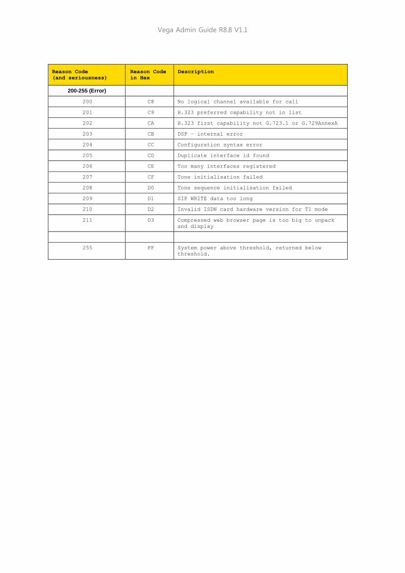
Vega Admin Guide R8.8 V1.1
Reason Code
(and seriousness)
Reason Code
in Hex
Description
200-255 (Error)
200 C8 No logical channel available for call
201 C9 H.323 preferred capability not in list
202 CA H.323 first capability not G.723.1 or G.729AnnexA
203 CB DSP – internal error
204 CC Configuration syntax error
205 CD Duplicate interface id found
206 CE Too many interfaces registered
207 CF Tone initialisation failed
208 D0 Tone sequence initialisation failed
209 D1 SIP WRITE data too long
210 D2 Invalid ISDN card hardware version for T1 mode
211 D3 Compressed web browser page is too big to unpack
and display
255 FF System power above threshold, returned below
threshold.
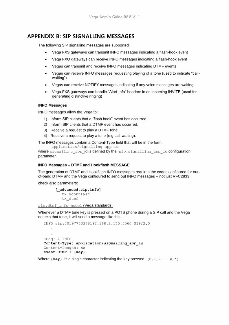
Vega Admin Guide R8.8 V1.1
APPENDIX B: SIP SIGNALLING MESSAGES
The following SIP signalling messages are supported:
Vega FXS gateways can transmit INFO messages indicating a flash-hook event
Vega FXO gateways can receive INFO messages indicating a flash-hook event
Vegas can transmit and receive INFO messages indicating DTMF events
Vegas can receive INFO messages requesting playing of a tone (used to indicate “call-waiting”)
Vegas can receive NOTIFY messages indicating if any voice messages are waiting
Vega FXS gateways can handle “Alert-Info” headers in an incoming INVITE (used for generating distinctive ringing)
INFO Messages
INFO messages allow the Vega to:
1) Inform SIP clients that a “flash hook” event has occurred.
2) Inform SIP clients that a DTMF event has occurred.
3) Receive a request to play a DTMF tone.
4) Receive a request to play a tone (e.g.call-waiting).
The INFO messages contain a Content-Type field that will be in the form: application/signalling_app_id
where signalling_app_id is defined by the sip.signalling_app_id configuration
parameter.
INFO Messages – DTMF and Hookflash MESSAGE
The generation of DTMF and Hookflash INFO messages requires the codec configured for out-of-band DTMF and the Vega configured to send out INFO messages – not just RFC2833.
check also parameters:
[_advanced.sip.info]
tx_hookflash
tx_dtmf
sip.dtmf_info=mode1 (Vega standard):
Whenever a DTMF tone key is pressed on a POTS phone during a SIP call and the Vega detects that tone, it will send a message like this:
INFO sip:[email protected]:5060 SIP/2.0
.
.
CSeq: 2 INFO
Content-Type: application/signalling_app_id
Content-Length: xx
event DTMF 1 {key}
Where {key} is a single character indicating the key pressed (0,1,2 .. #,*)
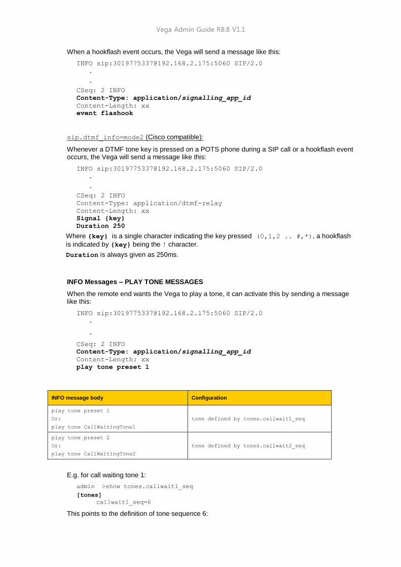
Vega Admin Guide R8.8 V1.1
When a hookflash event occurs, the Vega will send a message like this:
INFO sip:[email protected]:5060 SIP/2.0
.
.
CSeq: 2 INFO
Content-Type: application/signalling_app_id
Content-Length: xx
event flashook
sip.dtmf_info=mode2 (Cisco compatible):
Whenever a DTMF tone key is pressed on a POTS phone during a SIP call or a hookflash event occurs, the Vega will send a message like this:
INFO sip:[email protected]:5060 SIP/2.0
.
.
CSeq: 2 INFO
Content-Type: application/dtmf-relay
Content-Length: xx
Signal {key}
Duration 250
Where {key} is a single character indicating the key pressed (0,1,2 .. #,*), a hookflash
is indicated by {key} being the ! character.
Duration is always given as 250ms.
INFO Messages – PLAY TONE MESSAGES
When the remote end wants the Vega to play a tone, it can activate this by sending a message like this:
INFO sip:[email protected]:5060 SIP/2.0
.
.
CSeq: 2 INFO
Content-Type: application/signalling_app_id
Content-Length: xx
play tone preset 1
INFO message body Configuration
play tone preset 1
Or:
play tone CallWaitingTone1
tone defined by tones.callwait1_seq
play tone preset 2
Or:
play tone CallWaitingTone2
tone defined by tones.callwait2_seq
E.g. for call waiting tone 1:
admin >show tones.callwait1_seq
[tones]
callwait1_seq=6
This points to the definition of tone sequence 6:

Vega Admin Guide R8.8 V1.1
admin >show tones.seq.6
[tones.seq.6]
name=callwait1_seq
repeat=0
[tones.seq.6.tone.1]
duration=350
play_tone=7
NOTIFY Messages
NOTIFY messages allow the Vega to receive notification of waiting voice messages.
NOTIFY sip:[email protected] SIP/2.0
.
.
Cseq: 1 NOTIFY
Content-Type: text/plain
Content-Length: xx
Messages-Waiting: mw
Where mw can be:
yes
no
n where n=0,1,2,... and specifies the number of waiting messages
When the Vega receives a message where n>0 or mw is yes, then the Vega will:
1) Play a "stutter" dial-tone to the POTS user next time he/she takes the phone off-hook.
2) Send an MWI (message waiting indication) signal to the phone.
1. The stutter dial-tone is specified by tones.stutterd_seq. This defines which tone
sequence to use as the stutter dial-tone.
By default:
[tones]
stutterd_seq=2
2. To send an MWI signal to the phone, the Vega uses FSK tones. Some phones require a short voltage drop before the sending of the tones (like a hookflash) – this is not supported.
INVITE Messages with Alert-Info
Vega FXS gateways can handle INVITE messages containing an "Alert-Info" field. The Alert-Info header will look something like this:
Alert-Info: bellcore-r1
The Vega will try to match up the alert type (in this case, "bellcore-r1") to an
_advanced.pots.ring.x.name field in the configuration.
In this case, there would be a match with the following entry:
[_advanced.pots.ring.4]
name=bellcore-r1
frequency=20
repeat=1
NOTE

Vega Admin Guide R8.8 V1.1
ring1_on=350
ring1_off=350
ring2_on=900
ring2_off=300
ring3_on=350
ring3_off=3700
LIMITATIONS: This currently only works on calls on POTS interfaces that are in group 1, e.g.
pots.port.3.if.1
When NO "Alert-Info" field is present, then the Vega FXS port will use the ring specified by:
pots.port.x.if.1.ring_index where x (1-8) is the called POTS
interface.
If the "Alert-Info" field is present, then the Vega will try to use the ring specified.
INVITE Message Session Description
Some systems require the “c=” line to be in in the SDP media description, others require it in the
SDP session description. Vegas can support either requirement based on the configuration of
the parameter:
_advanced.sip.sdp.sess_desc_connection=0
the “c=” line appears in the SDP media description. For example:
v=0
o=Vega50 7 1 IN IP4 136.170.208.245
s=Sip Call
t=0 0
m=audio 10012 RTP/AVP 0
c=IN IP4 136.170.208.245
a=rtpmap:0 PCMU/8000
_advanced.sip.sdp.sess_desc_connection=1
the “c=” line appears in the SDP session description. For example:
v=0
o=Vega50 8 1 IN IP4 136.170.208.245
s=Sip Call
c=IN IP4 136.170.208.245
t=0 0
m=audio 10014 RTP/AVP 0
a=rtpmap:0 PCMU/8000

Vega Admin Guide R8.8 V1.1
APPENDIX C: DTMF TONE FREQUENCIES
Frequency (Hz) 1209Hz 1336Hz 1477Hz 1633Hz
Frequency (Hex) 0x4b9 0x538 0x5c5 0x661
697Hz 0x2b9 1 2 3 A
770Hz 0x302 4 5 6 B
852Hz 0x354 7 8 9 C
941Hz 0x3ad * 0 # D

Vega Admin Guide R8.8 V1.1
APPENDIX D: HEXADECIMAL TO DECIMAL CONVERSION
Hex Dec Hex Dec Hex Dec Hex Dec Hex Dec Hex Dec Hex Dec Hex Dec
00 0 20 32 40 64 60 96 80 128 A0 160 C0 192 E0 224
01 1 21 33 41 65 61 97 81 129 A1 161 C1 193 E1 225
02 2 22 34 42 66 62 98 82 130 A2 162 C2 194 E2 226
03 3 23 35 43 67 63 99 83 131 A3 163 C3 195 E3 227
04 4 24 36 44 68 64 100 84 132 A4 164 C4 196 E4 228
05 5 25 37 45 69 65 101 85 133 A5 165 C5 197 E5 229
06 6 26 38 46 70 66 102 86 134 A6 166 C6 198 E6 230
07 7 27 39 47 71 67 103 87 135 A7 167 C7 199 E7 231
08 8 28 40 48 72 68 104 88 136 A8 168 C8 200 E8 232
09 9 29 41 49 73 69 105 89 137 A9 169 C9 201 E9 233
0A 10 2A 42 4A 74 6A 106 8A 138 AA 170 CA 202 EA 234
0B 11 2B 43 4B 75 6B 107 8B 139 AB 171 CB 203 EB 235
0C 12 2C 44 4C 76 6C 108 8C 140 AC 172 CC 204 EC 236
0D 13 2D 45 4D 77 6D 109 8D 141 AD 173 CD 205 ED 237
0E 14 2E 46 4E 78 6E 110 8E 142 AE 174 CE 206 EE 238
0F 15 2F 47 4F 79 6F 111 8F 143 AF 175 CF 207 EF 239
10 16 30 48 50 80 70 112 90 144 B0 176 D0 208 F0 240
11 17 31 49 51 81 71 113 91 145 B1 177 D1 209 F1 241
12 18 32 50 52 82 72 114 92 146 B2 178 D2 210 F2 242
13 19 33 51 53 83 73 115 93 147 B3 179 D3 211 F3 243
14 20 34 52 54 84 74 116 94 148 B4 180 D4 212 F4 244
15 21 35 53 55 85 75 117 95 149 B5 181 D5 213 F5 245
16 22 36 54 56 86 76 118 96 150 B6 182 D6 214 F6 246
17 23 37 55 57 87 77 119 97 151 B7 183 D7 215 F7 247
18 24 38 56 58 88 78 120 98 152 B8 184 D8 216 F8 248
19 25 39 57 59 89 79 121 99 153 B9 185 D9 217 F9 249
1A 26 3A 58 5A 90 7A 122 9A 154 BA 186 DA 218 FA 250
1B 27 3B 59 5B 91 7B 123 9B 155 BB 187 DB 219 FB 251
1C 28 3C 60 5C 92 7C 124 9C 156 BC 188 DC 220 FC 252
1D 29 3D 61 5D 93 7D 125 9D 157 BD 189 DD 221 FD 253
1E 30 3E 62 5E 94 7E 126 9E 158 BE 190 DE 222 FE 254
1F 31 3F 63 5F 95 7F 127 9F 159 BF 191 DF 223 FF 255