Embed Size (px)
Citation preview
BusWorks® 900IP Series10/100M Industrial Ethernet I/O Modules
Technical Reference – EtherNet/IP™
INTRODUCTION TO ETHERNET/IP™
ACROMAG INCORPORATED Tel: (248) 624-154130765 South Wixom Road Fax: (248) 624-9234P.O. BOX 437Wixom, MI 48393-7037 U.S.A.
Copyright 2004, Acromag, Inc., Printed in the USA.Data and specifications are subject to change without notice. 8500-747-A04L000
Introduction To EtherNet/IP™__________________________________________________________________
______________________________________________________________________________________Acromag, Inc. Tel:248-624-1541 Fax:248-624-9234 Email:[email protected] http://www.acromag.com
2INTRODUCTION TO ETHERNET/IP
ABOUT ETHERNET/IP…………………..…………………… 3Why EtherNet/IP?...…………………………………….. 3About Determinism…………………………..……….… 4
THE OSI NETWORK MODEL……………...………………… 5TCP/IP Stack……………………………………………… 7Key Concepts & Terminology……………………….... 10
APPLICATION LAYER……………………………………….. 11Object-Oriented Terminology………………………… 11CIP™ – Control & Information Protocol….…………. 12CIP™ Encapsulation Message……………………….. 18Connection Manager……………………………………. 20
TRANSPORT LAYER……………………………………….... 22TCP – Transport Control Protocol…………..……….. 22TCP Example…………………………………………….. 25UDP – User Datagram Protocol………………………. 26
NETWORK LAYER……………………………………………. 28IP – Internet Protocol.………..…………………………. 28Ethernet (MAC) Address…..…………………………… 31Internet (IP) Address……………………………………. 31ARP – Address Resolution Protocol………………… 33RARP – Reverse Address Resolution Protocol……. 34
DATA LINK (MAC) LAYER.………………………………….. 35CSMA/CD – Carrier Sense Multiple Access w/CD…. 36MAC – Media Access Control (MAC) Protocol…….. 36Ethernet (MAC) Packet…..…………………………….. 36
EDS (ELECTRONIC DATA SHEET) FILE..……….………... 38Sample EDS File…………………………………………. 38
This information is provided as a service to our customers and to othersinterested in learning more about EtherNet/IP. Acromag assumes noresponsibility for any errors that may occur in this document, and makes nocommitment to update, or keep this information current.
Be sure to visit Acromag on the web at www.acromag.com.
Windows® is a registered trademark of Microsoft Corporation.Modbus® is a registered trademark of Modicon, Incorporated.The following is a trademark under license by ODVA: EtherNet/IP™.
All trademarks are the property of their respective owners.
TABLE OFCONTENTS
Introduction To EtherNet/IP™___________________________________________________________________
______________________________________________________________________________________Acromag, Inc. Tel:248-624-1541 Fax:248-624-9234 Email:[email protected] http://www.acromag.com
3The following information describes the operation of EtherNet/IP as it relatesto Acromag Series 900EN-60xx I/O modules. To download a copy of theEtherNet/IP standard, you may refer to the Open DeviceNet VendorAssociation (ODVA) web site for EtherNet/IP at www.ethernet-ip.org.
Acromag also manufactures a line of I/O modules that support ModbusTCP/IP and EtherNet/IP. Feel free to visit our website at www.acromag.comto obtain the latest information about these and other Acromag products.
EtherNet/IP was first presented in March of 2000 and is the result of a jointeffort between ControlNet International (CI), the Open DeviceNet VendorAssociation (ODVA), and the Industrial Ethernet Association (IEA), toproduce a network protocol that addresses the high demand for using thewidely popular Ethernet network in control applications.
In a nutshell, EtherNet/IP (Ethernet Industrial Protocol) is traditional Ethernetcombined with an industrial application layer protocol targeted to industrialautomation. This application layer protocol is the Control and InformationProtocol (CIP™).
IEEE 802.3 Ethernet is traditionally an office networking protocol that hasgained universal acceptance world-wide. It is an open standard supportedby many manufacturers and its infrastructure equipment is widely availableand largely installed. Likewise, its TCP/IP suite of protocols is foundeverywhere and also serves as the foundation for access to the World WideWeb. Since many devices already support Ethernet I/O, it is only natural toaugment it for use in industrial applications. As such, EtherNet/IP wascreated in an attempt to overcome the shortcomings of traditional IEEE802.3 Ethernet as applied to the industrial automation world.
For many years, the Control and Information Protocol (CIP™) has beenwidely used in industrial environments. CIP™ provides both real-time andinformational message structures, and is designed to be “wire-independent”in that it can work with any data-link and physical layer. As CIP™ is freelyavailable, accessible to anyone, easy to understand, and widely supportedby many manufacturers of industrial equipment, it is a natural candidate foruse in building other industrial communication standards. CIP™ was firstadopted by DeviceNet in 1994, which merged the popular CAN protocol withCIP™ to form DeviceNet. ControlNet was the next protocol to adopt CIP™in 1997. ControlNet is considered more deterministic and offered higherspeeds (up to 5MB) than DeviceNet, plus it extending the range of the busup to several kilometers with the use of repeaters.
Next, EtherNet/IP merged traditional IEEE 802.3 Ethernet with the Controland Information Protocol (CIP™) as its application layer to build an evenmore powerful industrial communication standard. EtherNet/IP shares thesame physical and data link layers of traditional IEEE 802.3 Ethernet anduses the same TCP/IP suite of protocols. This makes it fully compatible withexisting Ethernet hardware, such as cables, connectors, network interfacecards, hubs, and switches. Since EtherNet/IP uses the same applicationlayer protocol used by both DeviceNet and ControlNet, this allows theseprotocols to share common device profiles and object libraries, and alsohelps to make these types of devices interoperable on the same network.
ABOUTETHERNET/IP
Why EtherNet/IP?
Introduction To EtherNet/IP™__________________________________________________________________
______________________________________________________________________________________Acromag, Inc. Tel:248-624-1541 Fax:248-624-9234 Email:[email protected] http://www.acromag.com
4EtherNet/IP is considered an open network standard for these reasons:
• Its physical and data link layers use standard IEEE 802.3 Ethernet.• Its network layer uses the TCP/IP suite of protocols.• It is supported by four independent networking organizations –
ControlNet International (CI), the Industrial Ethernet Organization(IEA), the Open DeviceNet Vendor Association (ODVA), and theIndustrial Automation Open Network Alliance (IAONA).
• EtherNet/IP technology is also available free of charge todevelopers and vendors. The EtherNet/IP standard can also bedownloaded free of charge from the ODVA web site.
Historically, traditional Ethernet was not considered a viable fieldbus forindustrial control and I/O networks because of two major shortcomings:inherent non-determinism, and low durability. However, new technologyproperly applied has mostly resolved these issues.
Originally, Ethernet equipment was designed for the office environment, notharsh industrial settings. Although, many factory Ethernet installations canuse this standard hardware without a problem, new industrial-ratedconnectors, shielded cables, and hardened switches and hubs are nowavailable to help resolve the durability issue.
With respect to the non-deterministic behavior of Ethernet, understand thatdeterminism is a term that is used here to describe the ability of a networkprotocol to guaranty that a packet is sent or received in a finite andpredictable amount of time. Thus, for critical control applications,determinism is very important.
The arbitration protocol for carrier transmission access on any Ethernetnetwork is called Carrier Sense Multiple Access with Collision Detect(CSMA/CD). Since any network device can try to send a data frame at anytime, with CSMA/CD applied, each device will first sense whether the line isidle and available for use. If the line is available, the device will then beginto transmit its first frame. If another device also tries to send a frame atapproximately the same time, then a collision occurs and both frames will bediscarded. Each device then waits a random amount of time and retries itstransmission until its frame is successfully sent. This channel-allocationmethod is inherently non-deterministic because a device may only transmitwhen the wire is free, resulting in unpredictable wait times before data maybe transmitted. Additionally, because of cable signaling delay, collisions arestill possible once the device begins to transmit the data, thus forcingadditional retransmission/retry cycles.
As most control systems have a defined time requirement for packettransmission, typically less than 100ms, the potential for collisions and theCSMA/CD method of retransmission is not considered deterministicbehavior. This is the reason that traditional Ethernet has had problemsbeing accepted for use in critical control applications. However, Ethernetcan be made more deterministic through the use of fast Ethernet switches,which increase the bandwidth of a large network by sub-dividing it intoseveral smaller networks or “collision domains”. The switch also provides adirect connection from the sender to the receiver such that only the receiverreceives the data, not the entire network.
Why EtherNet/IP?
About Determinism
Introduction To EtherNet/IP™___________________________________________________________________
______________________________________________________________________________________Acromag, Inc. Tel:248-624-1541 Fax:248-624-9234 Email:[email protected] http://www.acromag.com
5A switch (or switching hub) is an intelligent network device used to moreefficiently connect distributed Ethernet nodes. Each port of a switchforwards data to another port based on the MAC address contained in thereceived data packet/frame. The switch will actually learn and store theMAC addresses of every device it is connected to, along with the associatedport number. The port of a switch does not require its own MAC addressand during retransmission of a received packet, the switch port will insteadlook like the originating device by having assumed its source address. Inthis way, the Ethernet collision domain is said to terminate at the switch port,and the switch effectively breaks the network into separate distinct data linksor collision domains, one at each switch port. The ability of the switch totarget a packet to a specific port, rather than forwarding it to all switch ports,also helps to eliminate the collisions that make Ethernet non-deterministic.
Further, as switches have become less expensive, the current tendency incritical industrial control applications is to connect one Ethernet device perswitch port, effectively treating the switch device as the hub of a starnetwork. In this manner, with only one network device connected per switchport, the switch can run full-duplex, with no chance of collisions. Thus, a10/100 Ethernet switch effectively runs at 20/200 Mbps because it cantransmit and receive at 10 or 100 Mbps simultaneously (full duplex). Sincethere is only one device connected to a port, there is no chance of collisionsoccurring. The higher transfer speed of full-duplex coupled without the needfor invoking CSMA/CD produces a more deterministic mode of operation,helping critical control applications to remain predictable and on-time.
Unfortunately, broadcast traffic on a company network cannot be completelyfiltered by switches, and this may cause additional collisions reducing thedeterminism of a network connecting more than one device to a switch port.However, if the company network and the control & I/O network are insteadseparated, no traffic is added to the control network and its determinism isincreased. Further, if a bridge is used to separate the two networks, thenthe bridge can usually be configured to filter unnecessary traffic.
Combining good network design with fast switches and bridges wherenecessary raises the determinism of a network, making EtherNet/IP moreappealing. Other advances in Ethernet switches, such as, higher speeds,broadcast storm protection, virtual LAN support, SNMP, and prioritymessaging further help to increase the determinism of Ethernet networks.As Gigabit (Gbit), 10Gbit, and 100Gbit Ethernet enters the market,determinism will no longer be a concern.
With Ethernet as an open standard, numerous hardware and softwarevendors compete, resulting in low-cost, off-the-shelf products. As almosteveryone knows what Ethernet is, it’s also easier and more efficient to trainpeople on Ethernet than other networks. Currently, the research funding forEthernet far surpasses that of any other fieldbus, further enabling fasterdevelopment and increasingly higher speeds.
In order to better understand how EtherNet/IP is structured and the meaningof the term “open standard”, we need to review the Open SystemsInterconnect (OSI) Reference Model. This model was developed by theInternational Standards Organization and adopted in 1983 as a commonreference for the development of data communication standards. It doesnot attempt to define an implementation, but rather it serves as a structuralaide to understanding “what must be done” and “what goes where”.
About Determinism
THE OSI NETWORKMODEL
Introduction To EtherNet/IP™__________________________________________________________________
______________________________________________________________________________________Acromag, Inc. Tel:248-624-1541 Fax:248-624-9234 Email:[email protected] http://www.acromag.com
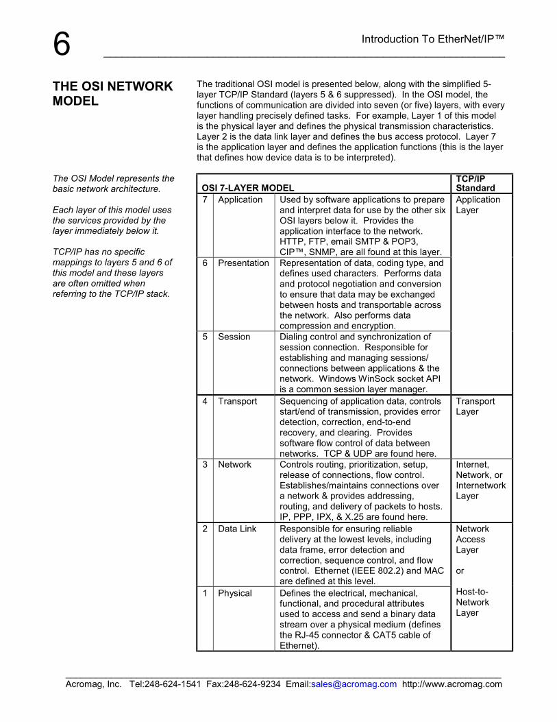
6The traditional OSI model is presented below, along with the simplified 5-layer TCP/IP Standard (layers 5 & 6 suppressed). In the OSI model, thefunctions of communication are divided into seven (or five) layers, with everylayer handling precisely defined tasks. For example, Layer 1 of this modelis the physical layer and defines the physical transmission characteristics.Layer 2 is the data link layer and defines the bus access protocol. Layer 7is the application layer and defines the application functions (this is the layerthat defines how device data is to be interpreted).
OSI 7-LAYER MODELTCP/IPStandard
7 Application Used by software applications to prepareand interpret data for use by the other sixOSI layers below it. Provides theapplication interface to the network.HTTP, FTP, email SMTP & POP3,CIP™, SNMP, are all found at this layer.
6 Presentation Representation of data, coding type, anddefines used characters. Performs dataand protocol negotiation and conversionto ensure that data may be exchangedbetween hosts and transportable acrossthe network. Also performs datacompression and encryption.
5 Session Dialing control and synchronization ofsession connection. Responsible forestablishing and managing sessions/connections between applications & thenetwork. Windows WinSock socket APIis a common session layer manager.
ApplicationLayer
4 Transport Sequencing of application data, controlsstart/end of transmission, provides errordetection, correction, end-to-endrecovery, and clearing. Providessoftware flow control of data betweennetworks. TCP & UDP are found here.
TransportLayer
3 Network Controls routing, prioritization, setup,release of connections, flow control.Establishes/maintains connections overa network & provides addressing,routing, and delivery of packets to hosts.IP, PPP, IPX, & X.25 are found here.
Internet,Network, orInternetworkLayer
2 Data Link Responsible for ensuring reliabledelivery at the lowest levels, includingdata frame, error detection andcorrection, sequence control, and flowcontrol. Ethernet (IEEE 802.2) and MACare defined at this level.
1 Physical Defines the electrical, mechanical,functional, and procedural attributesused to access and send a binary datastream over a physical medium (definesthe RJ-45 connector & CAT5 cable ofEthernet).
NetworkAccessLayer
or
Host-to-NetworkLayer
THE OSI NETWORKMODEL
The OSI Model represents thebasic network architecture.
Each layer of this model usesthe services provided by thelayer immediately below it.
TCP/IP has no specificmappings to layers 5 and 6 ofthis model and these layersare often omitted whenreferring to the TCP/IP stack.
Introduction To EtherNet/IP™___________________________________________________________________
______________________________________________________________________________________Acromag, Inc. Tel:248-624-1541 Fax:248-624-9234 Email:[email protected] http://www.acromag.com
7By the OSI Model, we can infer that in order for two devices to beinteroperable on the same network, they must have the same application-layer protocol. In the past, many network devices have used their ownproprietary protocols and this has hindered their interoperability. This factfurther drove the need for adoption of an open network I/O solution thatwould allow devices from a variety of vendors to seamlessly work together,and this drive for interoperability is a key reason EtherNet/IP was created.
Note that in the TCP/IP Standard Model, Ethernet handles the bottom 2layers (1 & 2) of the seven layer OSI stack, while TCP/IP handles the nexttwo layers (3 & 4). The application layer lies above TCP, IP, and Ethernetand is the layer of information that gives meaning to the transmitted data.
With Acromag 9xxEN-40xx Modbus TCP/IP modules, the application layerprotocol is Modbus. That is, Modbus TCP/IP uses Ethernet media andTCP/IP to communicate using an application layer with the same registeraccess method as Modbus RTU. Because many manufacturers happen tosupport Modbus RTU and TCP/IP, and since Modbus is also widelyunderstood and freely distributed, Modbus TCP/IP is also considered anopen standard.
With Acromag 9xxEN-60xx EtherNet/IP modules, the application layerprotocol is the Control and Information Protocol (CIP™). This is the sameapplication layer protocol used by ControlNet and DeviceNet devices. Bysharing the same application layer, these devices can be madeinteroperable on the same network.
EtherNet/IP is based on the TCP/IP protocol family and shares the samelower four layers of the OSI model common to all Ethernet devices. Thismakes it fully compatible with existing Ethernet hardware, such as cables,connectors, network interface cards, hubs, and switches. However,EtherNet/IP adds the Control and Information Protocol (CIP™) as itsapplication layer. This same application layer protocol is also used by bothDeviceNet and ControlNet devices. This makes each of these device typesinteroperable on the same network and also allows these protocols to sharecommon device profiles and object libraries.
TCP/IP refers to the Transmission Control Protocol and Internet Protocolwhich were first introduced in 1974. TCP/IP is the foundation for the WorldWide Web and forms the transport and network layer protocol of the internetthat commonly links all Ethernet installations world-wide. TCP/IP allowsblocks of binary data to be exchanged between computers. The primaryfunction of TCP is to ensure that all packets of data are received correctly,while IP makes sure that messages are correctly addressed and routed.Note that the TCP/IP combination does not define what the data means orhow the data is to be interpreted, it is merely a transport protocol. UDP(User-Datagram Protocol) is another transport layer protocol that isresponsible for ensuring prompt delivery of a data packet.
To contrast, CIP™ is an application protocol. It defines rules for organizingand interpreting data and is essentially a messaging structure that isindependent of the underlying physical layer. It is freely available andaccessible to anyone, easy to understand, and widely supported by manymanufacturers.
THE OSI NETWORKMODEL
Although the Acromag 9xxEN-60xx modules are designed forEtherNet/IP, they also providesupport for one additionalsocket of Modbus TCP/IP.
TCP/IP Stack
Introduction To EtherNet/IP™__________________________________________________________________
______________________________________________________________________________________Acromag, Inc. Tel:248-624-1541 Fax:248-624-9234 Email:[email protected] http://www.acromag.com
8EtherNet/IP uses TCP/IP, UDP/IP, and Ethernet to carry the data of theCIP™ message structure between devices. That is, EtherNet/IP combinesa physical network (Ethernet), with a networking standard (TCP/IP &UDP/IP), and a standard method of representing data (CIP™).
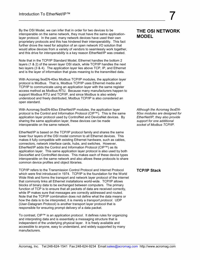
TCP/IP is actually formed from a “suite” of protocols upon which all internetcommunication is based. This suite of protocols is also referred to as aprotocol stack. Each host or router on the internet must run a protocolstack. The use of the word stack refers to the simplified TCP/IP layeredReference Model or “stack” that is used to design network software andoutlined as follows:
5 Application Specifies how an application uses a network.4 Transport Specifies how to ensure reliable data transport.3 Internet/Network Specifies packet format and routing.2 Host-to-Network Specifies frame organization and transmittal.1 Physical Specifies the basic network hardware.
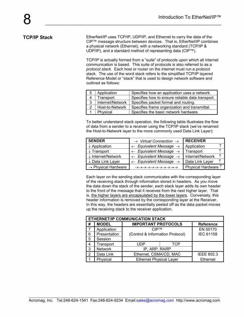
To better understand stack operation, the following table illustrates the flowof data from a sender to a receiver using the TCP/IP stack (we’ve renamedthe Host-to-Network layer to the more commonly used Data Link Layer):
SENDER → Virtual Connection → RECEIVER↓ Application ← Equivalent Message → Application ↑↓ Transport ← Equivalent Message → Transport ↑↓ Internet/Network ← Equivalent Message → Internet/Network ↑↓ Data Link Layer ← Equivalent Message → Data Link Layer ↑→ Physical Hardware →→→→→→→→→→→ Physical Hardware ↑
Each layer on the sending stack communicates with the corresponding layerof the receiving stack through information stored in headers. As you movethe data down the stack of the sender, each stack layer adds its own headerto the front of the message that it receives from the next higher layer. Thatis, the higher layers are encapsulated by the lower layers. Conversely, thisheader information is removed by the corresponding layer at the Receiver.In this way, the headers are essentially peeled off as the data packet movesup the receiving stack to the receiver application.
ETHERNET/IP COMMUNICATION STACK# MODEL IMPORTANT PROTOCOLS Reference7 Application CIP™ EN 501706 Presentation (Control & Information Protocol) IEC 611585 Session4 Transport UDP TCP3 Network IP, ARP, RARP2 Data Link Ethernet, CSMA/CD, MAC IEEE 802.31 Physical Ethernet Physical Layer Ethernet
TCP/IP Stack
Introduction To EtherNet/IP™___________________________________________________________________
______________________________________________________________________________________Acromag, Inc. Tel:248-624-1541 Fax:248-624-9234 Email:[email protected] http://www.acromag.com
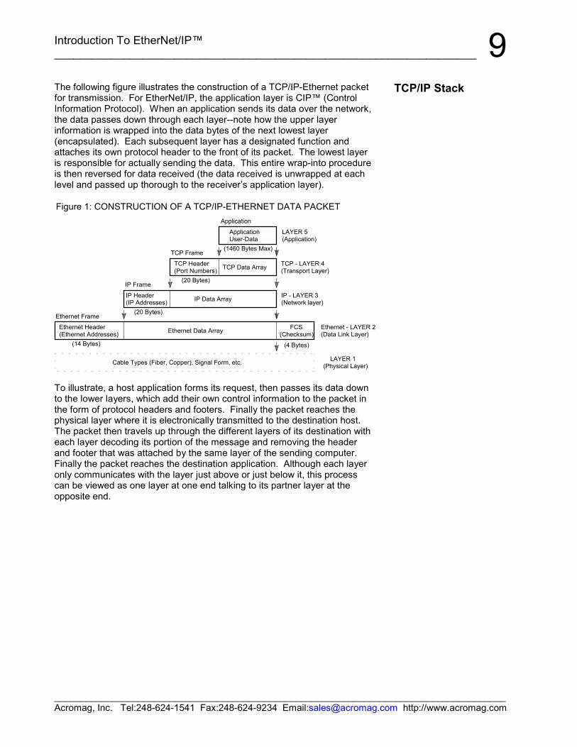
9The following figure illustrates the construction of a TCP/IP-Ethernet packetfor transmission. For EtherNet/IP, the application layer is CIP™ (ControlInformation Protocol). When an application sends its data over the network,the data passes down through each layer--note how the upper layerinformation is wrapped into the data bytes of the next lowest layer(encapsulated). Each subsequent layer has a designated function andattaches its own protocol header to the front of its packet. The lowest layeris responsible for actually sending the data. This entire wrap-into procedureis then reversed for data received (the data received is unwrapped at eachlevel and passed up thorough to the receiver’s application layer).
(20 Bytes)
Ethernet Frame
Ethernet Header(Ethernet Addresses) Ethernet Data Array
IP Data Array
TCP Data Array
TCP Frame(1460 Bytes Max)
Application
LAYER 1(Physical Layer)
Ethernet - LAYER 2(Data Link Layer)
(14 Bytes)
TCP Header(Port Numbers)
ApplicationUser-Data
Cable Types (Fiber, Copper), Signal Form, etc.
(4 Bytes)
FCS(Checksum)
(20 Bytes)
IP Frame
IP - LAYER 3(Network layer)
TCP - LAYER 4(Transport Layer)
LAYER 5(Application)
IP Header(IP Addresses)
Figure 1: CONSTRUCTION OF A TCP/IP-ETHERNET DATA PACKET
To illustrate, a host application forms its request, then passes its data downto the lower layers, which add their own control information to the packet inthe form of protocol headers and footers. Finally the packet reaches thephysical layer where it is electronically transmitted to the destination host.The packet then travels up through the different layers of its destination witheach layer decoding its portion of the message and removing the headerand footer that was attached by the same layer of the sending computer.Finally the packet reaches the destination application. Although each layeronly communicates with the layer just above or just below it, this processcan be viewed as one layer at one end talking to its partner layer at theopposite end.
TCP/IP Stack
Introduction To EtherNet/IP™__________________________________________________________________
______________________________________________________________________________________Acromag, Inc. Tel:248-624-1541 Fax:248-624-9234 Email:[email protected] http://www.acromag.com
10To better understand EtherNet/IP and the operation of a stack, pleasereview the following key concepts and terminology:
• All network functions are structured as a layered model.• There's one or more protocols (layer entities) at every layer.• Peer entities refer to two or more protocols on the same layer. This
may also refer to protocols at the same layer on different nodes.• Operation rules between peer entities are called procedures.• Protocol refers to the rules of operation followed by peer entities.
The Protocol defines the format of PDU’s (Protocol Data Units) andtheir rules of operation.
• This layering of protocol entities is referred to as the protocol stack.• Layer n communicates with other layer n entities (other protocols on
the same layer) using layer n Protocol Data Units (PDU’s).• Layer n uses the service of layer n-1 and offers a service to layer
n+1.• The interface between a layer and the layer above it is referred to as
the Service Access Point (SAP). The interface data between thelayers is the Service Data Unit (SDU).
• Protocols are either connection oriented or connectionless. Aconnection implies that the communication requires synchronizationof all parties before data can be exchanged.
• EtherNet/IP follows the Client-Server model.• A server is any program that awaits data requests to be sent to it.
Servers do not initiate contact with clients, but only respond to them.• A client is any network device that sends data requests to servers.• A port is an address that is used locally at the transport layer (on
one node) and identifies the source and destination of the packetinside the same node. Port numbers are divided between well-known port numbers (0-1023), registered user port numbers (1024-49151), and private/dynamic port numbers (49152-65535). Portsallow TCP/IP to multiplex and demultiplex a sequence of IPdatagrams that need to go to many different (simultaneous)application processes.
• A socket is an application layer address that is formed from thecombination of an IP address and port number (expressed as <HostIP Address>:<Port Number> or <Host Name>:<Port Number>) andis used as the overall identification address of an applicationprocess. Application protocols use this to keep track of the portnumber assigned to each instance of an application when usingUDP or TCP.
Key Concepts &Terminology
Introduction To EtherNet/IP™___________________________________________________________________
______________________________________________________________________________________Acromag, Inc. Tel:248-624-1541 Fax:248-624-9234 Email:[email protected] http://www.acromag.com
11The uppermost layer of the TCP/IP and OSI Reference Models is theApplication Layer. There are many application layer protocols that mayreside here, such as FTP, Telnet, HTTP, SMPT, DNS, and NNTP, amongothers. While each of these protocols has their own specific purpose, forEtherNet/IP, the primary application layer protocol of interest is CIP™(Control Information Protocol).
Before we look at CIP™, we have to become familiar with some basic objectoriented concepts and terminology, as CIP™ is built using objects.
An object is defined by attributes and behaviors. The term attributes refersto the information that differentiates one object from another. We useattributes to refer to the data of an object. The data stored within an objectdefines the state of the object. We use the term behaviors to refer to theoperations or methods the object uses to manipulate its data or attributes.The behavior of an object is what the object can do and this behavior iscontained within its methods. You use methods to operate on the data.Every attribute of an object will have a corresponding method and youinvoke a method by sending a message to it. Messages are thecommunication mechanism between objects. CIP™ object models will use“get” and “set” messages as the methods to access their data.
Thus, we define an object as an entity that contains both data and behavior.This is key to understanding what an object is—that is, it combines the dataand the behavior into one complete package. In this way, we also say thatthe object encapsulates its data and behavior. Contrast this to non-objectoriented or procedural programming, in which the data and the behavior arekept separate.
In this way, there is no global data in an object. The object controls accessto its attributes and methods, and some object members (both data andmethods) are hidden from other objects. As a rule, objects do not normallymanipulate the internal data of other objects. Access to the attributes withinthe object are controlled by the object itself. The restriction of access tocertain attributes and method functions is referred to as data hiding. Detailsnot important to the use of an object should be hidden from other objectsand an object should only reveal the interface necessary to interact with it.
Objects are also modeled after classes. A class is like a template fromwhich specific objects are made. In this way, the class is like a blueprint forthe object. Because objects are created from classes, the classes mustdefine the basic building blocks of objects (its data, behavior, andmessages). A class will define the attributes and behaviors that all objectscreated from this class will possess.
APPLICATIONLAYER
Object-OrientedTerminology

Introduction To EtherNet/IP™__________________________________________________________________
______________________________________________________________________________________Acromag, Inc. Tel:248-624-1541 Fax:248-624-9234 Email:[email protected] http://www.acromag.com
12The TCP/IP protocol suite (or stack of independent protocols) provides allthe resources for two devices to communicate with each other over anEthernet Local-Area Network (LAN), or global Wide-Area Network (WAN).However, TCP/IP only guarantees that application messages will betransferred between these devices, it does not guaranty that these deviceswill actually understand or interoperate with one another. For EtherNet/IPdevices, this capability is provided by the Control and Information Protocol(CIP™), or its more modern reference, the Common Industrial Protocol.
EtherNet/IP, ControlNet, and DeviceNet all share the Control andInformation Protocol (CIP™) at their application layer. For example,DeviceNet is basically CIP™ running on a CAN bus. Similarly, EtherNet/IPis CIP™ over TCP/UDP/IP. Because ControlNet, DeviceNet, andEtherNet/IP all have CIP™ in common, they also share an extensive objectlibrary and collection of pre-defined device profiles.
CIP™ is built using the distributed object model. That is, this modelcombines appropriate functionality with data by way of distributed objects.These objects are used to model the behavior of varied application entities.An object is an instance of a class and contains member functions(methods) that are only specified in the class as operations. Although CIP™defines a public set of operations, the methods of implementation areseparate and application-specific. Object oriented applications make it easyto hide data and implementation details by using hierarchies of classes andother object oriented features.
All CIP™ devices are modeled as a collection of objects. An objectrepresents a particular component of a device. Each object has properties(data) and methods (commands). We use the term class to refer to aspecific type or set of objects (same kind of system components), and objectinstance to refer to one implementation of a class (the object instance is theactual representation of a particular object within a class). Each instance ofa class has the same attributes, but its own particular set of attribute values.The term attribute refers to a characteristic of an instance, an object, or anobject class. Attributes provide status information and govern the operationof an object. Services are used to trigger the object/class to perform a task.The object’s response is referred to as its behavior. This collection ofrelated data values and common elements that make up the device form itsobject model. Note that the term object and class are often usedinterchangeably, even though a class is really a specific type of object.Users access these objects through the application layer and this accessremains the same, regardless of which network type hosts the device. Theapplication programmer doesn’t even need to know to which network adevice is connected, as this operation remains transparent to him.
To summarize, we say that a class is a specific type of object. An instanceis one implementation of a class, and an attribute is a characteristic of aninstance. For example, if our object is fruit, we can say that an apple is aclass of fruit. A Macintosh apple is an instance of this class, and red skin isone attribute of this particular instance.
A class exists simply to combine data for I/O messaging among commonelements. The CIP™ library already contains many commonly definedobjects or classes and there are at least 46 object classes currently defined.
CIP™ – Control &Information Protocol
Introduction To EtherNet/IP™___________________________________________________________________
______________________________________________________________________________________Acromag, Inc. Tel:248-624-1541 Fax:248-624-9234 Email:[email protected] http://www.acromag.com
13For example, discrete input, discrete output, analog input, analog output,position controller, and AC drive are all classes defined in CIP™. TheseCIP™ objects or classes define the device access, behavior, andextensions, and this allows different device types to be accessed using acommon mechanism—in this case, the object model. It’s important to makethe distinction that the CIP™ standard does not specify how these objectsare to be implemented, only what data values or attributes must be providedand made available to other CIP™ devices.
The objects and their components are addressed by a uniform addressingscheme that utilizes the following:
• Class Identifier or Class ID – An integer ID value assigned to eachobject class and accessible from the network.
• Instance Identifier or Instance ID – An integer ID value assignedto an object instance that identifies it among all instances of thesame class.
• Attribute Identifier or Attribute ID – An integer ID value assignedto a class and/or instance attribute.
• Service Code – An integer ID value which denotes a particularobject instance and/or object class function.
• Media Access Control Identifier (MAC ID) – An integer ID valueassigned to each node on the network.
CIP™ makes use of object models to provide a standard method fortransferring automation data between devices on the network. And becauseindividual objects are only added to a device’s object model according to thespecific functionality of the device, a device is not burdened with theunnecessary overhead of support for objects it can’t use. CIP™ alreadyincludes a large collection of commonly defined objects or object classes.While only a few of these objects are actually specific to the network linklayer (only two objects are specific to EtherNet/IP for example—TCP/IPInterface Object & Ethernet Link Object), the majority are common objectsthat can be used across all CIP™ based networks. Though most deviceswill use some of these publicly defined objects, device vendors are free tocreate their own vendor-specific objects and these are denoted by class ID’s100-199.
EtherNet/IP devices are further grouped into two general device classes:adapters or scanners. Adapters are I/O devices which provide data to ascanner. For example, Acromag 9xxEN modules are adapters. Scannersare explicit I/O devices which configure adapters to produce their data.
CIP™ uses the producer/consumer-based connection model, rather thanthe more traditional source/destination model. This model implies that as amessage is produced onto the network, it is identified by its connection ID,not its destination address. Multiple nodes may also have the right toconsume the data to which this connection ID refers. If a node wants toreceive data, it only needs to ask for it one time in order to consume thedata each time it is produced. Likewise, if a second node (or any number ofadditional nodes) require the same data, all they need to know is theconnection ID to receive the same data simultaneously with all the othernodes.
CIP™ – Control &Information Protocol
The ability of different devicesfrom different vendors tocommunicate up through theapplication layer makes theminteroperable.
Thus, on any network, in orderfor two devices to be fullyinteroperable, they must sharea common application layer.
To illustrate the benefits ofsharing a common applicationlayer protocol, consider thatnetworks sometimes usedevices called gateways to linknetworks of different types.The gateway converts oneprotocol to another. Forexample, an existing ProfiBusnetwork can be linked to anEthernet network via agateway, but this is expensiveand the conversion process isoften slow. On the other hand,connecting a DeviceNetnetwork to an Ethernetnetwork is made much easierbecause they share the sameapplication layer protocol.Although a gateway devicemay be used, the twonetworks only require a routerthat embeds the DeviceNetpacket inside a TCP/IP packetto become interoperable.Because there is noconversion, the router is lesscomplex, making it faster andless expensive.
Introduction To EtherNet/IP™__________________________________________________________________
______________________________________________________________________________________Acromag, Inc. Tel:248-624-1541 Fax:248-624-9234 Email:[email protected] http://www.acromag.com
14CIP™ provides many standard services for control of network devices andaccess to their data via implicit and explicit messages. Recall that implicitI/O messages refer to message exchanges that are time-sensitive (real-time), while explicit messages emphasize reliability and are used formessages that simply must get there. The type of messaging required willdetermine which specific transport layer protocol will be used, TCP(explicit/information), or UDP (implicit/control). The UDP/IP/MAC protocolstack will typically handle implicit messages and there are four general typesof implicit messages: polled, change-of-state, cyclic, and strobed. TheTCP/IP/MAC protocol stack will handle the explicit messages, which aresimple point-to-point messages. The key thing to remember about implicitmessages is that there can be many consumers of a single network packetand this requires UDP, while TCP is instead reserved for point-to-pointmessages.
There are four general types of implicit messages supported by CIP™:polled, strobed, cyclic, and change-of-state. With EtherNet/IP, only polledand cyclic are used while DeviceNet and ControlNet use all four. Polledmessages are those in which a master device (scanner) sequentiallyqueries all of the slave devices (adapters) by sending them their outputdata, and receiving a reply with their input data. Strobed is a special case ofpolled in which the scanner sends out a single multicast request for dataand the slaves sequentially respond with their data with no furthermessages required from the master. Cyclic messages are produced by adevice according to a pre-determined schedule and are associated with aconnection ID (cyclic messages are implicit). Any other device that requiresthe data of the producer is made aware of the connection ID and acceptsthe network packets associated with this connection ID. Change-of-state islike cyclic, except that its data is produced in response to an event whichcaused the data to change, rather than a timed schedule. Change-of-statedevices must maintain a background cycle/rate (their heartbeat) to allowconsuming devices to know that the node is online and functioning.
At this point, it’s important to understand the distinction between the type ofmessaging that CIP™ may use. This type will then determine which lowerlevel service and subsequent encapsulation will be performed, TCP/IP/MACor UDP/IP/MAC. In general, the control portion of CIP™ makes use of real-time I/O messaging or implicit messaging. The information portion of CIP™is used for simple message exchange or explicit messaging. TCP may onlywork with unicast (point-to-point) messages. UDP is typically used forimplicit messages, while TCP is used for explicit messages as outlined inthe following table:
CIP™ – Control &Information Protocol
Introduction To EtherNet/IP™___________________________________________________________________
______________________________________________________________________________________Acromag, Inc. Tel:248-624-1541 Fax:248-624-9234 Email:[email protected] http://www.acromag.com
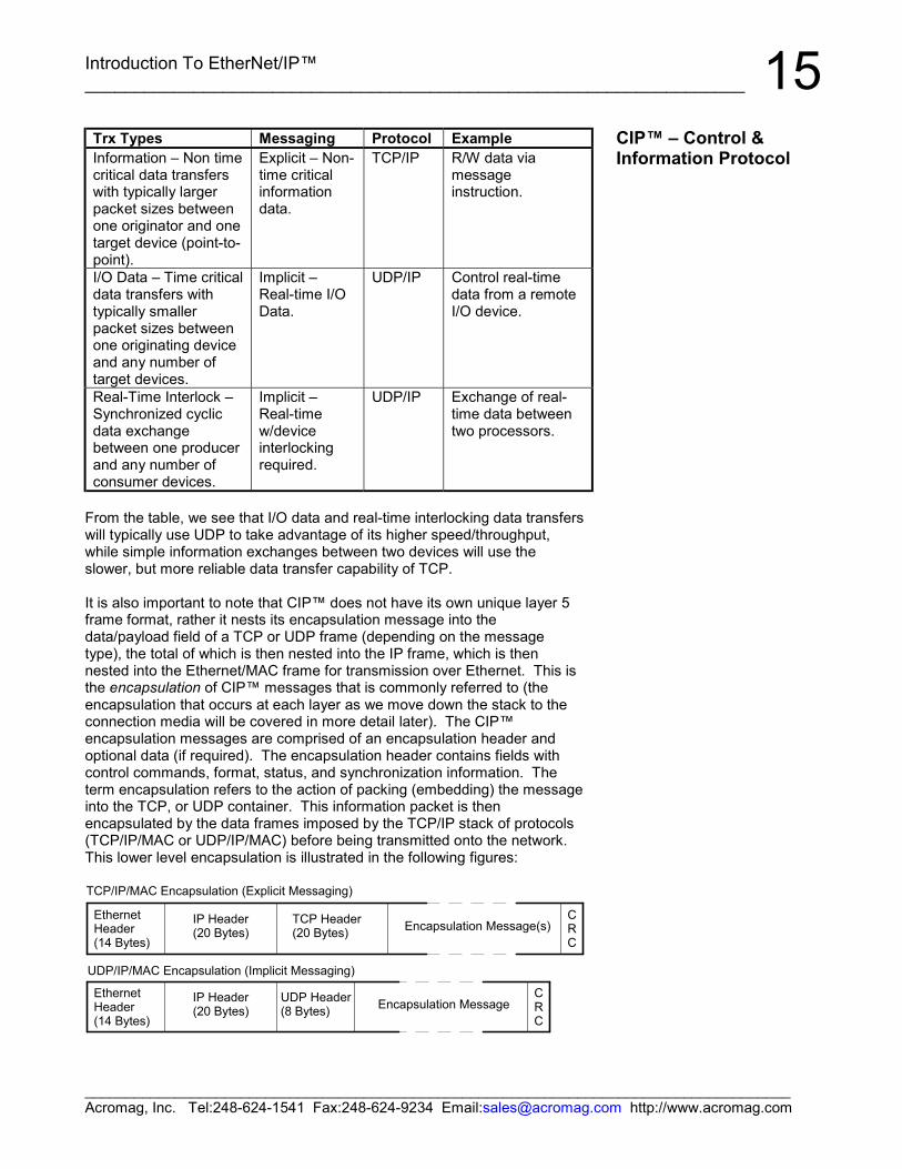
15Trx Types Messaging Protocol ExampleInformation – Non timecritical data transferswith typically largerpacket sizes betweenone originator and onetarget device (point-to-point).
Explicit – Non-time criticalinformationdata.
TCP/IP R/W data viamessageinstruction.
I/O Data – Time criticaldata transfers withtypically smallerpacket sizes betweenone originating deviceand any number oftarget devices.
Implicit –Real-time I/OData.
UDP/IP Control real-timedata from a remoteI/O device.
Real-Time Interlock –Synchronized cyclicdata exchangebetween one producerand any number ofconsumer devices.
Implicit –Real-timew/deviceinterlockingrequired.
UDP/IP Exchange of real-time data betweentwo processors.
From the table, we see that I/O data and real-time interlocking data transferswill typically use UDP to take advantage of its higher speed/throughput,while simple information exchanges between two devices will use theslower, but more reliable data transfer capability of TCP.
It is also important to note that CIP™ does not have its own unique layer 5frame format, rather it nests its encapsulation message into thedata/payload field of a TCP or UDP frame (depending on the messagetype), the total of which is then nested into the IP frame, which is thennested into the Ethernet/MAC frame for transmission over Ethernet. This isthe encapsulation of CIP™ messages that is commonly referred to (theencapsulation that occurs at each layer as we move down the stack to theconnection media will be covered in more detail later). The CIP™encapsulation messages are comprised of an encapsulation header andoptional data (if required). The encapsulation header contains fields withcontrol commands, format, status, and synchronization information. Theterm encapsulation refers to the action of packing (embedding) the messageinto the TCP, or UDP container. This information packet is thenencapsulated by the data frames imposed by the TCP/IP stack of protocols(TCP/IP/MAC or UDP/IP/MAC) before being transmitted onto the network.This lower level encapsulation is illustrated in the following figures:
CRC
Encapsulation Message(s)
IP Header(20 Bytes)
UDP Header(8 Bytes)
TCP Header(20 Bytes)
IP Header(20 Bytes)
CRC
UDP/IP/MAC Encapsulation (Implicit Messaging)
TCP/IP/MAC Encapsulation (Explicit Messaging)
EthernetHeader(14 Bytes)
Encapsulation Message
EthernetHeader(14 Bytes)
CIP™ – Control &Information Protocol
Introduction To EtherNet/IP™__________________________________________________________________
______________________________________________________________________________________Acromag, Inc. Tel:248-624-1541 Fax:248-624-9234 Email:[email protected] http://www.acromag.com
16Some CIP™ messages are only sent via TCP, while others may be sent viaTCP or UDP. As TCP is a data-stream based protocol, it may send almostany length IP packet it chooses, and it can parse this message as required.For example, it may encapsulate two back-to-back encapsulation messagesin a single TCP/IP/MAC packet, or it may divide an encapsulation messageacross two separate TCP/IP/MAC packets. However, with UDP, only onemessage may be encapsulated at a time via UDP/IP/MAC.
In general, there are three types of objects or classes defined by CIP™—required objects, application or device-specific objects, and vendor-specificobjects. Required objects must be included in every CIP™ device. Device-specific objects are the objects that define the data encapsulated by thedevice and are specific to the type of device and its function. Objects notfound in the profile for a device class are vendor-specific objects and thesevendor extensions are usually included as additional features of the device.
The confusion that surrounds this topic usually arises from the nesting ofobjects and classes that occurs in defining other objects and classes, and inlinking together these various objects to build larger device profiles.
Required objects must be included in every CIP™ device and these includean identity object, a message router object, and a network object. MostEtherNet/IP devices require the following objects:
• An Identification Object (Identity Object)• A Connection Object (Connection Manager Object)• One or more Network Link Objects (Ethernet Link & TCP Objects)• A Message Router Object (Message Router Object)
The identity object contains related identity data values or attributes,including the vendor ID, date of manufacture, the device serial number, andother identity data. A network object contains the physical connection datafor the object. For example, for a DeviceNet CIP™ device, the networkobject contains the MAC ID and other data describing the interface to theCAN network. For an EtherNet/IP device, the network object contains the IPaddress and other data describing the interface to the Ethernet port on thedevice. The message router object routes explicit request messages fromobject to object in a device. Additional objects are added to the device’sobject model according to its functionality.
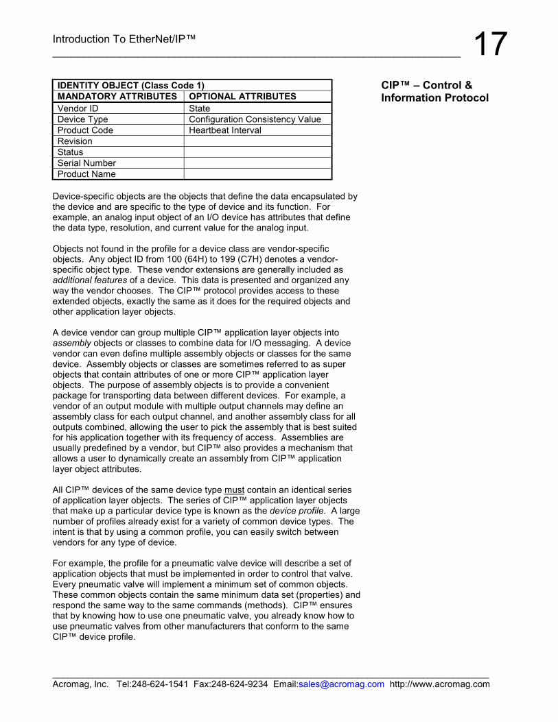
The following table lists the instance attributes of the Identity Object (classcode 1), which is a required public object. All the attributes of the identityobject are read-only, as devices do not change their identity (except for theoptional heartbeat interval attribute).
CIP™ – Control &Information Protocol
Introduction To EtherNet/IP™___________________________________________________________________
______________________________________________________________________________________Acromag, Inc. Tel:248-624-1541 Fax:248-624-9234 Email:[email protected] http://www.acromag.com
17IDENTITY OBJECT (Class Code 1)MANDATORY ATTRIBUTES OPTIONAL ATTRIBUTESVendor ID StateDevice Type Configuration Consistency ValueProduct Code Heartbeat IntervalRevisionStatusSerial NumberProduct Name
Device-specific objects are the objects that define the data encapsulated bythe device and are specific to the type of device and its function. Forexample, an analog input object of an I/O device has attributes that definethe data type, resolution, and current value for the analog input.
Objects not found in the profile for a device class are vendor-specificobjects. Any object ID from 100 (64H) to 199 (C7H) denotes a vendor-specific object type. These vendor extensions are generally included asadditional features of a device. This data is presented and organized anyway the vendor chooses. The CIP™ protocol provides access to theseextended objects, exactly the same as it does for the required objects andother application layer objects.
A device vendor can group multiple CIP™ application layer objects intoassembly objects or classes to combine data for I/O messaging. A devicevendor can even define multiple assembly objects or classes for the samedevice. Assembly objects or classes are sometimes referred to as superobjects that contain attributes of one or more CIP™ application layerobjects. The purpose of assembly objects is to provide a convenientpackage for transporting data between different devices. For example, avendor of an output module with multiple output channels may define anassembly class for each output channel, and another assembly class for alloutputs combined, allowing the user to pick the assembly that is best suitedfor his application together with its frequency of access. Assemblies areusually predefined by a vendor, but CIP™ also provides a mechanism thatallows a user to dynamically create an assembly from CIP™ applicationlayer object attributes.
All CIP™ devices of the same device type must contain an identical seriesof application layer objects. The series of CIP™ application layer objectsthat make up a particular device type is known as the device profile. A largenumber of profiles already exist for a variety of common device types. Theintent is that by using a common profile, you can easily switch betweenvendors for any type of device.
For example, the profile for a pneumatic valve device will describe a set ofapplication objects that must be implemented in order to control that valve.Every pneumatic valve will implement a minimum set of common objects.These common objects contain the same minimum data set (properties) andrespond the same way to the same commands (methods). CIP™ ensuresthat by knowing how to use one pneumatic valve, you already know how touse pneumatic valves from other manufacturers that conform to the sameCIP™ device profile.
CIP™ – Control &Information Protocol
Introduction To EtherNet/IP™__________________________________________________________________
______________________________________________________________________________________Acromag, Inc. Tel:248-624-1541 Fax:248-624-9234 Email:[email protected] http://www.acromag.com
18From a device manufacturer’s perspective, the use of common profiles maysound too restrictive for a manufacturer trying to offer unique features andcapabilities to his products. But understand that although the use ofcommon device profiles exist, a manufacturer may still incorporateadditional features into its products via additional objects and attributesbeyond those defined in the common device profile. A vendors’conformance to an existing device profile simply allows his customers todefine to a core set of objects and attributes without regard to the devicemanufacturer.
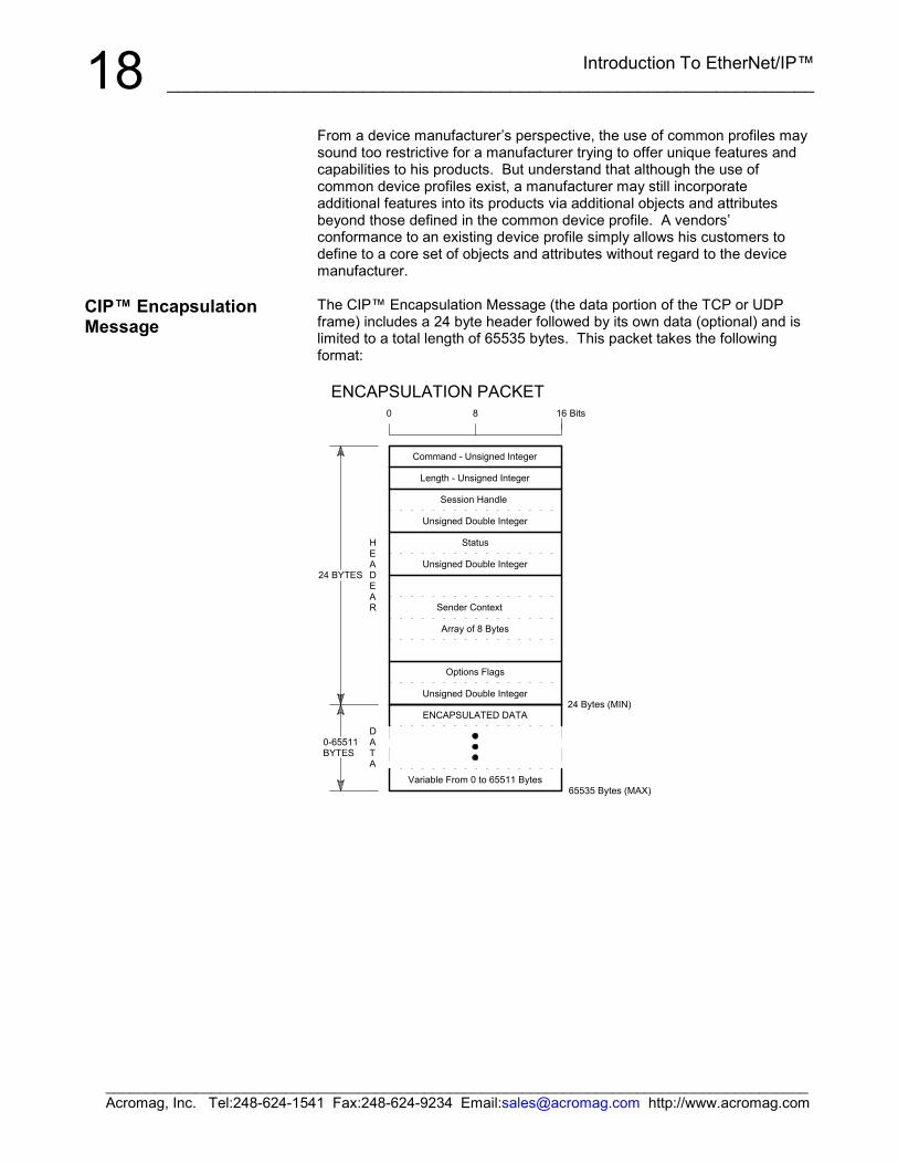
The CIP™ Encapsulation Message (the data portion of the TCP or UDPframe) includes a 24 byte header followed by its own data (optional) and islimited to a total length of 65535 bytes. This packet takes the followingformat:
8
24 BYTES
0
Status
Bits
0-65511BYTES
DATA
HEADEAR
65535 Bytes (MAX)
24 Bytes (MIN)
16
Variable From 0 to 65511 Bytes
Unsigned Double Integer
ENCAPSULATED DATA
Options Flags
Array of 8 Bytes
Unsigned Double Integer
Sender Context
Session Handle
Unsigned Double Integer
Command - Unsigned Integer
Length - Unsigned Integer
ENCAPSULATION PACKET
CIP™ EncapsulationMessage
Introduction To EtherNet/IP™___________________________________________________________________
______________________________________________________________________________________Acromag, Inc. Tel:248-624-1541 Fax:248-624-9234 Email:[email protected] http://www.acromag.com
19CIP™ Encapsulation Packet Definitions (Left-to-Right, Top-to-Bottom):
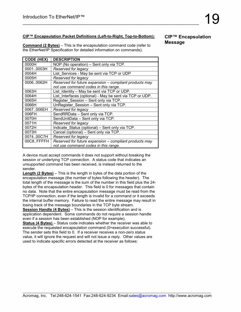
Command (2 Bytes) – This is the encapsulation command code (refer tothe EtherNet/IP Specification for detailed information on commands):
CODE (HEX) DESCRIPTION0000H NOP (No operation) – Sent only via TCP.0001..0003H Reserved for legacy0004H List_Services - May be sent via TCP or UDP0005H Reserved for legacy0006..0062H Reserved for future expansion – compliant products may
not use command codes in this range.0063H List_Identity – May be sent via TCP or UDP.0064H List_Interfaces (optional) - May be sent via TCP or UDP.0065H Register_Session – Sent only via TCP.0066H UnRegister_Session – Sent only via TCP.0067..006EH Reserved for legacy006FH SendRRData – Sent only via TCP.0070H SendUnitData – Sent only via TCP.0071H Reserved for legacy0072H Indicate_Status (optional) – Sent only via TCP.0073H Cancel (optional) – Sent only via TCP.0074..00C7H Reserved for legacy00C8..FFFFH Reserved for future expansion – compliant products may
not use command codes in this range.
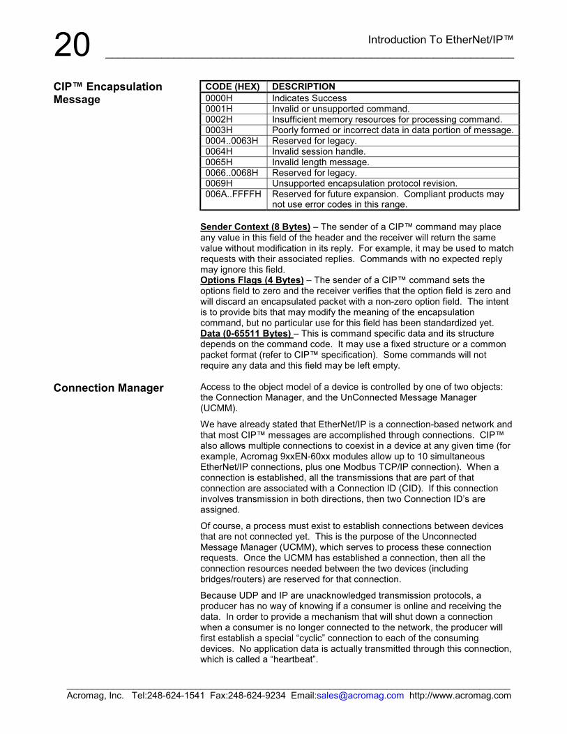
A device must accept commands it does not support without breaking thesession or underlying TCP connection. A status code that indicates anunsupported command has been received, is instead returned to thesender.Length (2 Bytes) – This is the length in bytes of the data portion of theencapsulation message (the number of bytes following the header). Thetotal length of the message is the sum of the number in this field plus the 24-bytes of the encapsulation header. This field is 0 for messages that containno data. Note that the entire encapsulation message must be read from theTCP/IP connection, even if the length is invalid for a command or it exceedsthe internal buffer memory. Failure to read the entire message may result inlosing track of the message boundaries in the TCP byte stream.Session Handle (4 Bytes) – This is the session identification and isapplication dependent. Some commands do not require a session handleeven if a session has been established (NOP for example).Status (4 Bytes) – Status code indicates whether the receiver was able toexecute the requested encapsulation command (0=execution successful).The sender sets this field to 0. If a receiver receives a non-zero statusvalue, it will ignore the request and will not issue a reply. Other values areused to indicate specific errors detected at the receiver as follows:
CIP™ EncapsulationMessage
Introduction To EtherNet/IP™__________________________________________________________________
______________________________________________________________________________________Acromag, Inc. Tel:248-624-1541 Fax:248-624-9234 Email:[email protected] http://www.acromag.com
20CODE (HEX) DESCRIPTION0000H Indicates Success0001H Invalid or unsupported command.0002H Insufficient memory resources for processing command.0003H Poorly formed or incorrect data in data portion of message.0004..0063H Reserved for legacy.0064H Invalid session handle.0065H Invalid length message.0066..0068H Reserved for legacy.0069H Unsupported encapsulation protocol revision.006A..FFFFH Reserved for future expansion. Compliant products may
not use error codes in this range.
Sender Context (8 Bytes) – The sender of a CIP™ command may placeany value in this field of the header and the receiver will return the samevalue without modification in its reply. For example, it may be used to matchrequests with their associated replies. Commands with no expected replymay ignore this field.Options Flags (4 Bytes) – The sender of a CIP™ command sets theoptions field to zero and the receiver verifies that the option field is zero andwill discard an encapsulated packet with a non-zero option field. The intentis to provide bits that may modify the meaning of the encapsulationcommand, but no particular use for this field has been standardized yet.Data (0-65511 Bytes) – This is command specific data and its structuredepends on the command code. It may use a fixed structure or a commonpacket format (refer to CIP™ specification). Some commands will notrequire any data and this field may be left empty.
Access to the object model of a device is controlled by one of two objects:the Connection Manager, and the UnConnected Message Manager(UCMM).
We have already stated that EtherNet/IP is a connection-based network andthat most CIP™ messages are accomplished through connections. CIP™also allows multiple connections to coexist in a device at any given time (forexample, Acromag 9xxEN-60xx modules allow up to 10 simultaneousEtherNet/IP connections, plus one Modbus TCP/IP connection). When aconnection is established, all the transmissions that are part of thatconnection are associated with a Connection ID (CID). If this connectioninvolves transmission in both directions, then two Connection ID’s areassigned.
Of course, a process must exist to establish connections between devicesthat are not connected yet. This is the purpose of the UnconnectedMessage Manager (UCMM), which serves to process these connectionrequests. Once the UCMM has established a connection, then all theconnection resources needed between the two devices (includingbridges/routers) are reserved for that connection.
Because UDP and IP are unacknowledged transmission protocols, aproducer has no way of knowing if a consumer is online and receiving thedata. In order to provide a mechanism that will shut down a connectionwhen a consumer is no longer connected to the network, the producer willfirst establish a special “cyclic” connection to each of the consumingdevices. No application data is actually transmitted through this connection,which is called a “heartbeat”.
CIP™ EncapsulationMessage
Connection Manager
Introduction To EtherNet/IP™___________________________________________________________________
______________________________________________________________________________________Acromag, Inc. Tel:248-624-1541 Fax:248-624-9234 Email:[email protected] http://www.acromag.com
21If the producer times out all of the heartbeat connections that are associatedwith a specific produced data object, then all connections associated withthat data object are closed.
All connections on a CIP™ network can be divided into I/O connections(implicit), and explicit messaging connections.
Recall that explicit message connections are point-to-point communicationpaths between two devices. They follow a simple request/response networkcommunication format and are always made to the message router (theMessage Router Object). Each request contains explicit information (nottime critical) that the receiving node decodes and acts upon, then generatesan appropriate response. Thus, all explicit connections are directconnections between two devices, which require a source address, adestination address, and a connection ID in each direction. Explicitmessages are normally triggered by events that are external to the CIP™application layer.
Implicit message connections provide dedicated special purposecommunication paths (or ports) between a producer application object andone or more consumer application objects. They follow theproducer/consumer-based connection model and contain implicit (time-sensitive data. The data is implicit because it is identified at the time thatthe connection is established and the connection ID’s are assigned and wesay that the data is implicitly defined by its connection ID. Implicitmessaging is commonly used for I/O messages and takes place within theapplication layer of the protocol with both the producer node and consumingnodes aware of the message content before transmission. Its chiefdistinction is that there can be many simultaneous consumers of a singlepacket of data produced on the network. For implicit communication, theUDP/IP/MAC protocol stack is used, which supports the requisite multicastcommunication (UDP also supports unicast and broadcast communication,while TCP is restricted to unicast only).
UDP packets are not transmitted directly to the actual IP address of areceiving device, but are transmitted using a specific device allocated IPmulticast address. This address is used in parallel with the CIP™connection ID, allowing packets that are not relevant to a specific node to befiltered out ahead of being presented to the application layer. But theconsuming device must first be made aware of this IP multicast address(which was allocated by the producer) before it can use the data produced.The Unconnected Message Manager is used to accomplish this.
Connection Manager
Introduction To EtherNet/IP™__________________________________________________________________
______________________________________________________________________________________Acromag, Inc. Tel:248-624-1541 Fax:248-624-9234 Email:[email protected] http://www.acromag.com
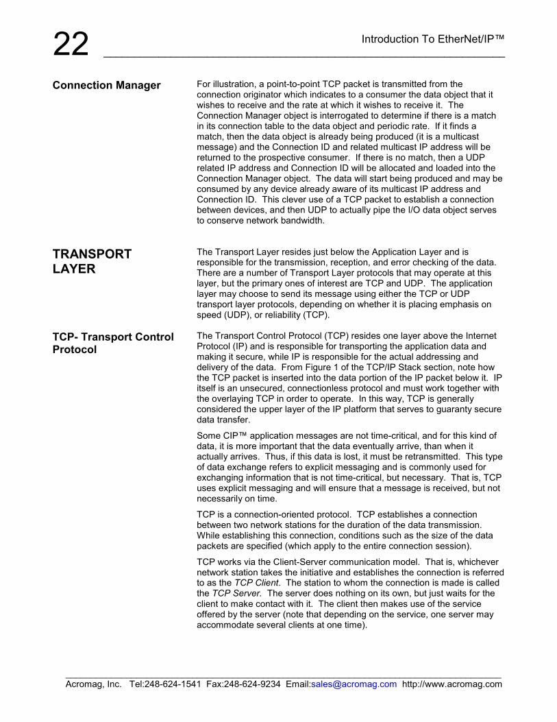
22For illustration, a point-to-point TCP packet is transmitted from theconnection originator which indicates to a consumer the data object that itwishes to receive and the rate at which it wishes to receive it. TheConnection Manager object is interrogated to determine if there is a matchin its connection table to the data object and periodic rate. If it finds amatch, then the data object is already being produced (it is a multicastmessage) and the Connection ID and related multicast IP address will bereturned to the prospective consumer. If there is no match, then a UDPrelated IP address and Connection ID will be allocated and loaded into theConnection Manager object. The data will start being produced and may beconsumed by any device already aware of its multicast IP address andConnection ID. This clever use of a TCP packet to establish a connectionbetween devices, and then UDP to actually pipe the I/O data object servesto conserve network bandwidth.
The Transport Layer resides just below the Application Layer and isresponsible for the transmission, reception, and error checking of the data.There are a number of Transport Layer protocols that may operate at thislayer, but the primary ones of interest are TCP and UDP. The applicationlayer may choose to send its message using either the TCP or UDPtransport layer protocols, depending on whether it is placing emphasis onspeed (UDP), or reliability (TCP).
The Transport Control Protocol (TCP) resides one layer above the InternetProtocol (IP) and is responsible for transporting the application data andmaking it secure, while IP is responsible for the actual addressing anddelivery of the data. From Figure 1 of the TCP/IP Stack section, note howthe TCP packet is inserted into the data portion of the IP packet below it. IPitself is an unsecured, connectionless protocol and must work together withthe overlaying TCP in order to operate. In this way, TCP is generallyconsidered the upper layer of the IP platform that serves to guaranty securedata transfer.
Some CIP™ application messages are not time-critical, and for this kind ofdata, it is more important that the data eventually arrive, than when itactually arrives. Thus, if this data is lost, it must be retransmitted. This typeof data exchange refers to explicit messaging and is commonly used forexchanging information that is not time-critical, but necessary. That is, TCPuses explicit messaging and will ensure that a message is received, but notnecessarily on time.
TCP is a connection-oriented protocol. TCP establishes a connectionbetween two network stations for the duration of the data transmission.While establishing this connection, conditions such as the size of the datapackets are specified (which apply to the entire connection session).
TCP works via the Client-Server communication model. That is, whichevernetwork station takes the initiative and establishes the connection is referredto as the TCP Client. The station to whom the connection is made is calledthe TCP Server. The server does nothing on its own, but just waits for theclient to make contact with it. The client then makes use of the serviceoffered by the server (note that depending on the service, one server mayaccommodate several clients at one time).
Connection Manager
TRANSPORTLAYER
TCP- Transport ControlProtocol
Introduction To EtherNet/IP™___________________________________________________________________
______________________________________________________________________________________Acromag, Inc. Tel:248-624-1541 Fax:248-624-9234 Email:[email protected] http://www.acromag.com
23TCP verifies the sent user data with a checksum and assigns a sequentialnumber to each packet sent. The receiver of a TCP packet uses thechecksum to verify having received the data correctly. Once the TCP serverhas correctly received the packet, it uses a predetermined algorithm tocalculate an acknowledgement number from the sequential number. Theacknowledgement number is returned to the client with the next packet itsends as an acknowledgement. The server also assigns a sequentialnumber to the packet it sends, which is then subsequently acknowledged bythe client with an acknowledgement number. This process helps to ensurethat any loss of TCP packets will be noticed and that if needed, they canthen be re-sent in the correct sequence.
TCP also directs the user data on the destination computer to the correctapplication program by accessing various application services using variousport numbers. For example, Telnet can be reached through Port 23, FTPthrough port 21, and Modbus through port 502. In this way, the port numberis analogous to the room number in a large office building—if you address aletter to the public relations office in room 312, you are indicating that youwish to utilize the services of the public relations office. A port is theaddress that is used locally at the transport layer (on one node) andidentifies the source and destination of the packet inside the same node.Port numbers are divided between well-known port numbers (0-1023),registered user port numbers (1024-49151), and private/dynamic portnumbers (49152-65535). Ports allow TCP/IP to multiplex and demultiplex asequence of IP datagrams that need to go to many different (simultaneous)application processes.
To reiterate, note that with TCP, the transmitter expects the receiver toacknowledge receipt of the data packets. Failure to acknowledge receipt ofthe packet will cause the transmitter to send the packet again, or thecommunication link to be broken. Because each packet is numbered, thereceiver can also determine if a data packet is missing, or it can reorderpackets not received into the correct order. If any data is detected asmissing, all subsequent received data will be buffered. The data will then bepassed up the protocol stack to the application, but only when it is completeand in the correct order. Of course this error checking mechanism of theconnection-oriented TCP protocol takes time and will operate more slowlythan a connection-less protocol like UDP. Thus, sending a message viaTCP only makes sense where continuous data streams or large quantities ofdata must be exchanged, or where a high degree of data integrity isrequired (with the emphasis being on secure data).
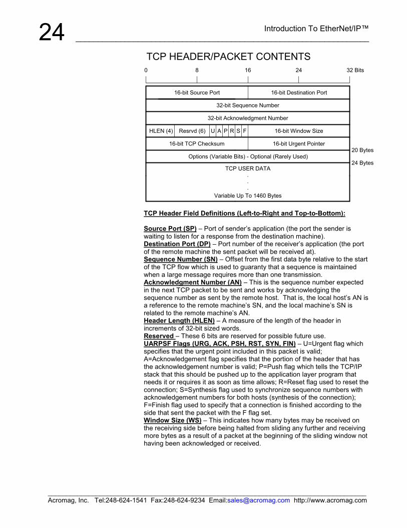
The following figure illustrates the construction of a TCP Packet:
TCP- Transport ControlProtocol
With respect the port numberscommonly used inEtherNet/IP, UDP/UCM willuse port 4418, UDP I/O willuse port 2222, and CIP™ TCPwill use 4418.
Introduction To EtherNet/IP™__________________________________________________________________
______________________________________________________________________________________Acromag, Inc. Tel:248-624-1541 Fax:248-624-9234 Email:[email protected] http://www.acromag.com
248
.
.
.
A P S F
0 16 24
20 Bytes
24 Bytes
32 Bits
U R
16-bit TCP Checksum 16-bit Urgent Pointer
HLEN (4) Resrvd (6)
16-bit Source Port
16-bit Window Size
16-bit Destination Port
Variable Up To 1460 Bytes
TCP USER DATA
Options (Variable Bits) - Optional (Rarely Used)
32-bit Acknowledgment Number
32-bit Sequence Number
TCP HEADER/PACKET CONTENTS
TCP Header Field Definitions (Left-to-Right and Top-to-Bottom):
Source Port (SP) – Port of sender’s application (the port the sender iswaiting to listen for a response from the destination machine).Destination Port (DP) – Port number of the receiver’s application (the portof the remote machine the sent packet will be received at).Sequence Number (SN) – Offset from the first data byte relative to the startof the TCP flow which is used to guaranty that a sequence is maintainedwhen a large message requires more than one transmission.Acknowledgment Number (AN) – This is the sequence number expectedin the next TCP packet to be sent and works by acknowledging thesequence number as sent by the remote host. That is, the local host’s AN isa reference to the remote machine’s SN, and the local machine’s SN isrelated to the remote machine’s AN.Header Length (HLEN) – A measure of the length of the header inincrements of 32-bit sized words.Reserved – These 6 bits are reserved for possible future use.UARPSF Flags (URG, ACK, PSH, RST, SYN, FIN) – U=Urgent flag whichspecifies that the urgent point included in this packet is valid;A=Acknowledgement flag specifies that the portion of the header that hasthe acknowledgement number is valid; P=Push flag which tells the TCP/IPstack that this should be pushed up to the application layer program thatneeds it or requires it as soon as time allows; R=Reset flag used to reset theconnection; S=Synthesis flag used to synchronize sequence numbers withacknowledgement numbers for both hosts (synthesis of the connection);F=Finish flag used to specify that a connection is finished according to theside that sent the packet with the F flag set.Window Size (WS) – This indicates how many bytes may be received onthe receiving side before being halted from sliding any further and receivingmore bytes as a result of a packet at the beginning of the sliding window nothaving been acknowledged or received.
Introduction To EtherNet/IP™___________________________________________________________________
______________________________________________________________________________________Acromag, Inc. Tel:248-624-1541 Fax:248-624-9234 Email:[email protected] http://www.acromag.com
25
DFT RST
9
5
1
8
4
0
11
7
3
ETHERNET
ACTLINK
ST
NIC
CH
. I/O
STA
TUS
10
6
2
RUN
Acromag
UDP
SAP
TCP
80
NETWORKROUTER
IP (Network Layer)
1 - OPEN (SYN)
Ethernet (Data Link Layer)
TCP UDP
SAP
CLIENT(WEB Browser)
Open Connection To255.255.255.100: 80
Physical Layer
Ethernet (Data Link Layer)
IP (Network Layer)
Passively Open(Listening)
IP Address is255.255.255.100Client PC Running Internet Explorer
Physical Layer (CAT5 Cable) Physical Layer (CAT5 Cable)
Ethernet (Data Link Layer)
2 - CONNECT (SYN ACK)
Application - WEB BROWSER Application - CIP, WEB SERVER
SIMPLIFIED CLIENT STACK SIMPLIFIED SERVER STACK
IP (Network Layer)
Acromag 983EN-6012
SIMPLIFIED ROUTER STACK
Socket Address is255.255.255.100:80
3 - CONNECT ACK (ACK) AND SEND DATA
EXAMPLE TCP TRANSACTION
PEER-TO-PEER COMMUNICATION80 is Web ServerPort Number forHTTP Protocol
TCP Checksum (TCPCS) – This is a checksum that covers the header anddata portion of a TCP packet to allow the receiving host to verify the integrityof an incoming TCP packet.Urgent Pointer (UP) – This allows for a section of data as specified by theurgent pointer to be passed up by the receiving host quickly.IP Options – These bits are optional and rarely used.TCP User Data – This portion of the packet may contain any number ofapplication layer protocols (CIP™, HTTP, SSH, FTP, Telnet, etc.).
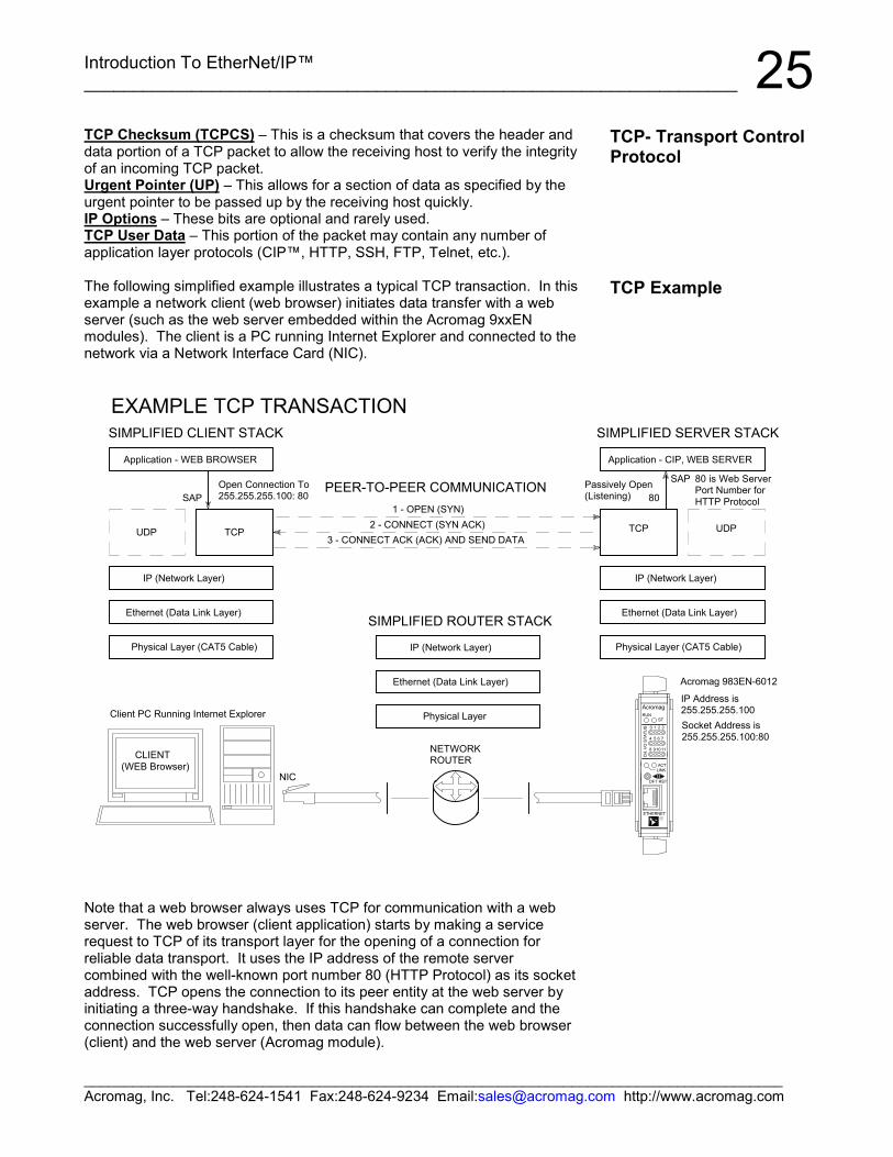
The following simplified example illustrates a typical TCP transaction. In thisexample a network client (web browser) initiates data transfer with a webserver (such as the web server embedded within the Acromag 9xxENmodules). The client is a PC running Internet Explorer and connected to thenetwork via a Network Interface Card (NIC).
Note that a web browser always uses TCP for communication with a webserver. The web browser (client application) starts by making a servicerequest to TCP of its transport layer for the opening of a connection forreliable data transport. It uses the IP address of the remote servercombined with the well-known port number 80 (HTTP Protocol) as its socketaddress. TCP opens the connection to its peer entity at the web server byinitiating a three-way handshake. If this handshake can complete and theconnection successfully open, then data can flow between the web browser(client) and the web server (Acromag module).
TCP- Transport ControlProtocol
TCP Example
Introduction To EtherNet/IP™__________________________________________________________________
______________________________________________________________________________________Acromag, Inc. Tel:248-624-1541 Fax:248-624-9234 Email:[email protected] http://www.acromag.com
26Once the connection is made, the web browser and remote server assumethat a reliable open data pipe has formed between them and they begintransporting their data in sequence, and without errors, as long as TCP doesnot close the connection. TCP will monitor the transaction for missingpackets and retransmit them as necessary to ensure reliability.
Note that in the figure above, an observer in the data paths at either side ofthe router would actually see the beginning of the message from the client tothe web server begin only in the third data frame exchanged (the client’srequest message is combined with the connection acknowledge of the thirdexchange).
Like TCP, the User Datagram Protocol (UDP) resides above IP and isanother protocol for transporting data, but with the emphasis being totransport it on-time, rather than to guaranty delivery. UDP is aconnectionless protocol that simply allows one device to send a datagram toanother device without guaranteed delivery, a retry mechanism, or anyacknowledgement.
Some CIP™ messages are time-critical and if this data is delayed, it losesits value. Thus, if the data is lost, there is no point in retransmitting it. Thistype of data exchange refers to implicit messaging and is commonly usedfor real-time or control data. Time-critical implicit messages of CIP™ aresent using UDP (User Datagram Protocol). UDP is faster than TCP andprovides the quick, efficient data transport necessary for real-time dataexchange.
Unlike TCP, UDP is a connectionless oriented protocol. That is, thetransmitter sends out a data packet, but does not expect to receive aconfirmation that the packet has arrived at its destination. Further, thereceiver accepts the incoming packets, but cannot tell if any packets aremissing or in the wrong order, and uncorrupted data packets are simplypassed up the protocol stack as they are received. The lack of any errorchecking overhead makes this protocol faster, though somewhat lessreliable. Ethernet, IP, and UDP are all connectionless protocols.
UDP packets are treated like separate mailings, with no confirmation ofpacket receipt. UDP does not require connections to be established orbroken off, thus no timeout situations occur. If a packet is lost, datatransmission will continue unabated, and a higher protocol will usually beresponsible for repetition. Data integrity under UDP is generally handled bythe application program itself. These characteristics effectively allow UDPto communicate much faster than TCP.
TCP Example
UDP – User DatagramProtocol
Introduction To EtherNet/IP™___________________________________________________________________
______________________________________________________________________________________Acromag, Inc. Tel:248-624-1541 Fax:248-624-9234 Email:[email protected] http://www.acromag.com
27Sending a message via UDP makes sense where transmission parametersare changing frequently and when data integrity can instead be assured bya higher order protocol (the emphasis again here is on time-critical data).
To contrast, sending a message via TCP makes sense where continuousdata streams or large quantities of data must be exchanged, or where a highdegree of data integrity is required (the emphasis here is on secure data).
EtherNet/IP uses both TCP and UDP in an intelligent way to provide moredeterministic performance. That is, time-critical implicit messages are sentusing the faster UDP, while explicit messages are sent securely using TCP.Any lost data will not prevent subsequent time-critical data from beingprocessed with UDP. The slower but more reliable TCP will instead ensurethat a message is received by retransmitting any lost data, but this processmay not be suitable for real-time data.
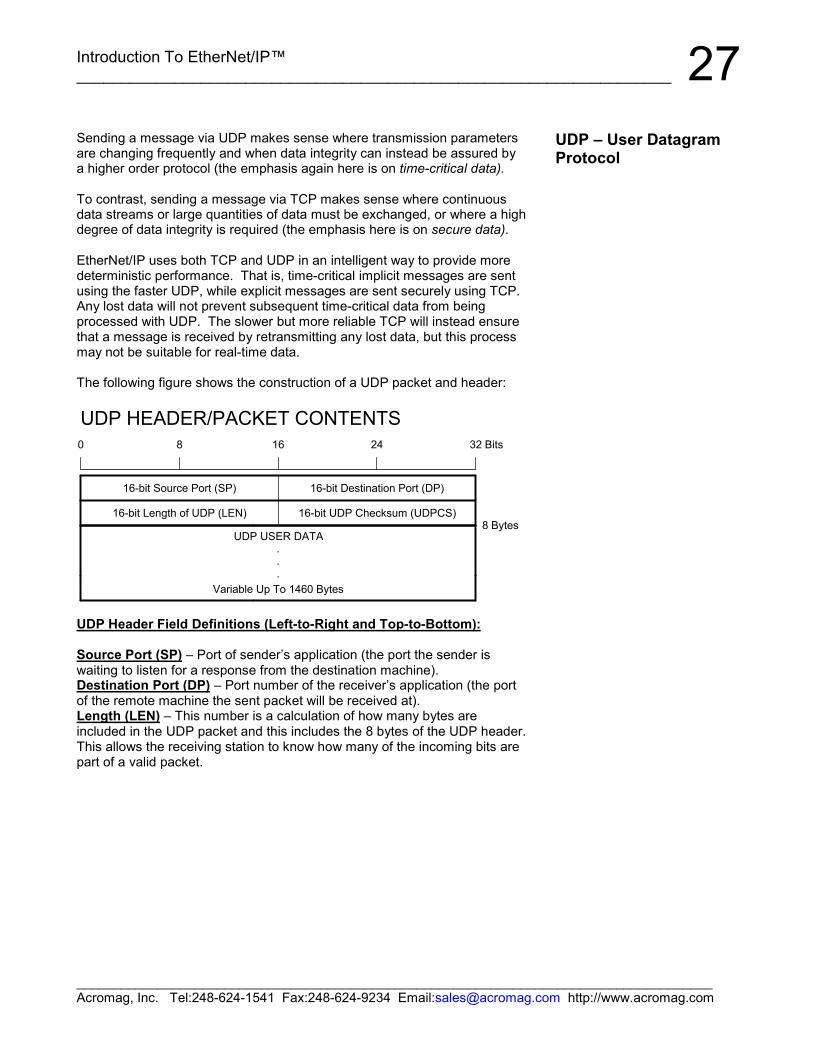
The following figure shows the construction of a UDP packet and header:
0 8
.
.
.
16 24 32
8 BytesUDP USER DATA
Bits
16-bit Destination Port (DP)
16-bit UDP Checksum (UDPCS)
16-bit Source Port (SP)
UDP HEADER/PACKET CONTENTS
Variable Up To 1460 Bytes
16-bit Length of UDP (LEN)
UDP Header Field Definitions (Left-to-Right and Top-to-Bottom):
Source Port (SP) – Port of sender’s application (the port the sender iswaiting to listen for a response from the destination machine).Destination Port (DP) – Port number of the receiver’s application (the portof the remote machine the sent packet will be received at).Length (LEN) – This number is a calculation of how many bytes areincluded in the UDP packet and this includes the 8 bytes of the UDP header.This allows the receiving station to know how many of the incoming bits arepart of a valid packet.
UDP – User DatagramProtocol
Introduction To EtherNet/IP™__________________________________________________________________
______________________________________________________________________________________Acromag, Inc. Tel:248-624-1541 Fax:248-624-9234 Email:[email protected] http://www.acromag.com
28UDP Checksum (UDPCS) – This checksum covers the header and dataportions of a UDP packet and is used to allow the receiving host to verify theintegrity of an incoming UDP packet. Note that the UDP packet is loadedwith a predefined number in the checksum field, and when the checksum iscomputed, then the new checksum is written over the previous value. Whenthe packet arrives at its destination, the destination machine’s operatingsystem extracts bits 16-31 of this field, then recalculates the checksum onthe packet without anything in the checksum field. Then the OS comparesthe calculated checksum to the one that was transmitted in the packet. Ifthey are the same, the data is judged reliable and allowed to pass through.If they are different, then the UDP packet and data are dropped and noattempt is made by the receiving machine to get a new copy, nor is thepacket retransmitted by the sending machine—the packet is thenpermanently lost. Because of this, UDP is considered unreliable. For amore reliable transport layer protocol, TCP is the better choice.UDP User Data – This portion of the packet may contain any number ofapplication layer protocols (NFS, DNS, audio/video streaming protocols,etc.). If an error occurs in a UDP packet, and it is desired that the error befixed, it is up to the application layer to find the error and request itsapplication layer to hunk/chunk the data.
The Network Layer or Internet Layer resides just below the Transport Layerand is responsible for routing the packets to the network. Although thereare many network layer protocols such as ICMP, IGMP, and others, themost important of these are IP, ARP, and RARP.
Although EtherNet/IP, TCP/IP, and UDP/IP are named together, they arereally complimentary protocols. The Internet Protocol (IP) manages theactual addressing and delivery of the data packets. IP provides aconnectionless and unacknowledged method for sending data packetsbetween two devices on a network. IP does not guaranty delivery of thedata packet, it relies on a transport layer protocol (like TCP) or applicationlayer protocol (like CIP™) to do that. IP also makes it possible to assemblean indefinite number of individual networks into a larger overall network,without regard to physical implementation of the sub networks. That is, thedata is sent from one network station to another, regardless of thesedifferences.
An IP packet is a chunk of data transferred over the Internet using standardInternet Protocol (IP). Each packet begins with a header containingaddressing and system control information. Unlike uniform ATM "cells", IPpackets vary in length depending on the data being transmitted.
The following illustrates the contents of the IP header. The first 5 rows arecommonly used (20 Bytes), while the 6th (or more) rows will depend on howmany 32-bit option words are required by special options. The data is theencapsulated packet of the upper Transport Layer (a TCP or UDP packet).
UDP – User DatagramProtocol
NETWORK LAYER
IP – Internet Protocol
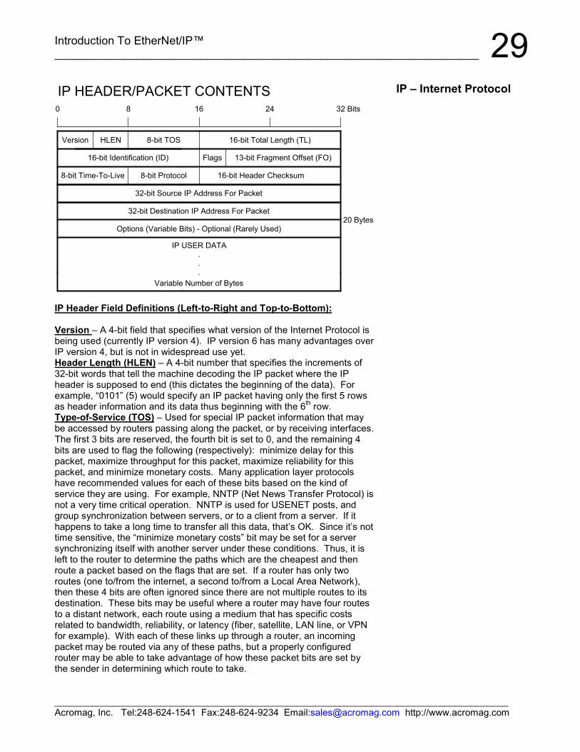
Introduction To EtherNet/IP™___________________________________________________________________
______________________________________________________________________________________Acromag, Inc. Tel:248-624-1541 Fax:248-624-9234 Email:[email protected] http://www.acromag.com
298
.
.
.
Version
0 16 24 32 Bits
16-bit Identification (ID)
8-bit TOSHLEN
20 Bytes
Flags
16-bit Total Length (TL)
13-bit Fragment Offset (FO)
8-bit Time-To-Live 16-bit Header Checksum
Variable Number of Bytes
IP USER DATA
32-bit Source IP Address For Packet
32-bit Destination IP Address For Packet
IP HEADER/PACKET CONTENTS
Options (Variable Bits) - Optional (Rarely Used)
8-bit Protocol
IP Header Field Definitions (Left-to-Right and Top-to-Bottom):
Version – A 4-bit field that specifies what version of the Internet Protocol isbeing used (currently IP version 4). IP version 6 has many advantages overIP version 4, but is not in widespread use yet.Header Length (HLEN) – A 4-bit number that specifies the increments of32-bit words that tell the machine decoding the IP packet where the IPheader is supposed to end (this dictates the beginning of the data). Forexample, “0101” (5) would specify an IP packet having only the first 5 rowsas header information and its data thus beginning with the 6th row.Type-of-Service (TOS) – Used for special IP packet information that maybe accessed by routers passing along the packet, or by receiving interfaces.The first 3 bits are reserved, the fourth bit is set to 0, and the remaining 4bits are used to flag the following (respectively): minimize delay for thispacket, maximize throughput for this packet, maximize reliability for thispacket, and minimize monetary costs. Many application layer protocolshave recommended values for each of these bits based on the kind ofservice they are using. For example, NNTP (Net News Transfer Protocol) isnot a very time critical operation. NNTP is used for USENET posts, andgroup synchronization between servers, or to a client from a server. If ithappens to take a long time to transfer all this data, that’s OK. Since it’s nottime sensitive, the “minimize monetary costs” bit may be set for a serversynchronizing itself with another server under these conditions. Thus, it isleft to the router to determine the paths which are the cheapest and thenroute a packet based on the flags that are set. If a router has only tworoutes (one to/from the internet, a second to/from a Local Area Network),then these 4 bits are often ignored since there are not multiple routes to itsdestination. These bits may be useful where a router may have four routesto a distant network, each route using a medium that has specific costsrelated to bandwidth, reliability, or latency (fiber, satellite, LAN line, or VPNfor example). With each of these links up through a router, an incomingpacket may be routed via any of these paths, but a properly configuredrouter may be able to take advantage of how these packet bits are set bythe sender in determining which route to take.
IP – Internet Protocol
Introduction To EtherNet/IP™__________________________________________________________________
______________________________________________________________________________________Acromag, Inc. Tel:248-624-1541 Fax:248-624-9234 Email:[email protected] http://www.acromag.com
30These bits are sometimes known as the Differentiated Services Code Point(DSCP) which defines one of a set of classes of service. This value isusually set to 0, but may be used to indicate a particular Quality of Servicerequest from the network.Total Length (TL) – The total length of the IP packet in 8-bit (byte)increments. By subtracting header length (HL) from total length (TL), youcan determine how many bytes long the data portion of the IP packet is. Asa 16-bit value, valid ranges would be from 20 (minimum size of IP header) to65535 bytes. A TL of only 20 is unlikely (no data), but could happen ifsomething was broken. Very large IP packets (greater than 1500 bytes) arealso uncommon, since they must typically be fragmented onto somenetworks.Identification (ID) – A 16-bit number used to distinguish one sent IP packetfrom another by having each IP packet sent increment the ID by 1 over theprevious IP packet sent.Flags – A sequence of 3 fragmentation flags used to control where routersare allowed to fragment a packet (via Don’t Fragment flag) and to indicatethe parts of a packet to the receiver: 001=More, 010=Don’t Fragment, 100=Unused.Fragmentation Offset (FO) – A byte count from the start of the originalpacket sent and set by any router that performs IP router fragmentation.Time-to-Live (TTL) – An 8-bit value that is used to limit the number ofrouters through which a packet may travel before reaching its destination(the number of hops/links which the packet may be routed over). Thisnumber is decremented by 1 by most routers and is used to preventaccidental routing loops. If the TTL drops to zero, the packet is discardedby either the server that has last decremented it, or the next server thatreceives it.Protocol – An 8-bit value that is used to allow the networking layer to knowwhat kind of transport layer protocol is in the data segment of the IP packet.For example, 1=ICMP, 2=IGMP, 6=TCP, 17=UDP.Header Checksum – A 16-bit checksum (1’s complement value) for theheader data that allows a packet to offer verification data to help ensure thatthe IP header is valid. This checksum is originally inserted by the senderand then updated whenever the packet header is modified by a router. Thisis used to detect processing errors on the part of the router or bridge wherethe packet is not already protected by a link layer cyclic redundancy check.Packets with an invalid checksum are discarded by all nodes in an IPnetwork.Source IP Address (32 bits) – The IP address of the source machinesending the data onto the network. This address is commonly representedby 4 octets representing decimal values and separated by periods(255.255.255.10 for example).Destination IP Address (32 bits) – The IP address of the destinationmachine to which the packet is being routed for delivery. This address iscommonly represented by 4 octets representing decimal values andseparated by periods (255.255.255.10 for example).Options (Variable Number of Bits/Words) – These bits are reserved forspecial features and are rarely used, but when they are used, the IP headerlength will be greater than 5 (five 32-bit words) to indicate the relative size ofthe option field.IP Data (Variable Number of Bits/Words) - This portion of the packet maycontain any number of nested protocols (TCP, UDP, ICMP, etc.).
IP – Internet Protocol
A Network's Infrastructureincludes the physical hardwareused to transmit dataelectronically such as routers,switches, gateways, bridges,and hubs.
A router is located at thegateway where it directs theflow of network traffic anddetermines the route ofpackets as they travel fromone network to anothernetwork(s). A router can beeither a hardware device or asoftware application.
Introduction To EtherNet/IP™___________________________________________________________________
______________________________________________________________________________________Acromag, Inc. Tel:248-624-1541 Fax:248-624-9234 Email:[email protected] http://www.acromag.com
31The Ethernet Address or MAC Address refers to the Media AccessControl Address that uniquely identifies the hardware of any network device.This is a unique, 48-bit, fixed address assigned and hard-coded into anEthernet device at the factory. This is usually expressed in hexadecimalform as 12 hex characters (6 bytes), with the first 3 bytes (6 leftmost hexcharacters) representing the device manufacturer, and the last 3 bytes (6rightmost hex characters) uniquely assigned by the manufacturer. All sixbytes taken together uniquely identify the network device.
Do not confuse the Ethernet Address (MAC address) with the InternetProtocol (IP) Address, which is a 32-bit number assigned to your computer(see below) that can change each time you connect to a network.
IP addresses are 32-bit numbers that are administered by an independentauthority (InterNIC) and are unique for any device on the network. The IPaddress is a 32-bit value made up of four octets (8 bits), with each octethaving a value between 0-255 (00H-FFH). It is commonly expressed asfour decimal numbers (8-bit values) separated by a decimal point. Thisprovides about 4.3 billion possible combinations.
Large networks of corporations, communications companies, and researchinstitutions will obtain large blocks of IP addresses, then divide them intosubnetworks within their own organization and distribute these addresses asthey see fit. The smaller networks of universities and companies willacquire smaller blocks of IP addresses to distribute among their users.Because these numbers are ultimately assigned by the Internet AssignedNumber’s Authority, the IP address can be used to approximate a machine’slocation.
Similar to the Ethernet Address, the IP address is comprised of two parts:the network address or Net ID (first part), and the host address or Host ID(last part). This last part refers to a specific machine on a given subnetwork(identified by the first part). The number of octets of the four total thatbelong to the network address depend on the Class definition (Class A, B,or C) and this refers to the size of the network.
A Subnet is a contiguous string of IP addresses. The first IP address in asubnet is used to identify the subnet and usually addresses the server forthe subnet. The last IP address in a subnet is always used as a broadcastaddress and anything sent to the last IP address of a subnet is sent to everyhost on that subnet.
Subnets are further broken down into three size classes based on the 4octets that make up the IP address. A Class A subnet is any subnet thatshares the first octet of the IP address. The remaining 3 octets of a Class Asubnet will define up to 16,777,214 possible IP addresses (224 – 2). A ClassB subnet shares the first two octets of an IP address (providing 216 – 2, or65534 possible IP addresses). Class C subnets share the first 3 octets ofan IP address, giving 254 possible IP addresses. Recall that the first andlast IP addresses are always used as a network number and broadcastaddress respectively, and this is why we subtract 2 from the total possibleunique addresses that are defined via the remaining octet(s).
Ethernet (MAC)Address
TIP: If you want to determinethe Ethernet address of theNIC card installed in your PC,at the DOS command prompt,type WINIPCFG <Enter>(Windows 98), or IPCONFIG/ALL <Enter> (Windows XP).
Internet (IP) Address
A Subnet Mask is used tosubdivide the host portion ofthe IP address into two ormore subnets. The subnetmask will flag the bits of the IPaddress that belong to thenetwork address, and theremaining bits correspond tothe host portion of theaddress. The unique subnetto which an IP address refersto is recovered by performinga bitwise AND operationbetween the IP address andthe mask itself, with the resultbeing the sub-networkaddress.
Introduction To EtherNet/IP™__________________________________________________________________
______________________________________________________________________________________Acromag, Inc. Tel:248-624-1541 Fax:248-624-9234 Email:[email protected] http://www.acromag.com
32A Subnet Mask is used to determine which subnet an IP address belongs to.The use of a subnet mask allows the network administrator to further dividethe host part of this address into two or more subnets. The subnet maskflags the network address part of the IP address, plus the bits of the hostpart, that are used for identifying the sub-network. By mask convention, thebits of the mask that correspond to the sub-network address are all set to1’s (it would also work if the bits were set exactly as in the network address).It’s called a mask because it can be used to identify the unique subnet towhich an IP address belongs to by performing a bitwise AND operationbetween the mask itself, and the IP address, with the result being the sub-network address, and the remaining bits the host or node address.
For our example, the default IP address of this module is 128.1.1.100. If weassume that this is a Class C network address (based on the default ClassC subnet mask of 255.255.255.0), then the first three numbers representthis Class C network at address 128.1.1.0, the last number identifies aunique host/node on this network (node 100) at address 128.1.1.100.
For our example, if we wish to further divide this network into 14 subnets,then the first 4 bits of the host address will be required to identify thesubnetwork (0110), then we would use “11111111.11111111.11111111.11110000” as our subnet mask. This would effectively subdivide our ClassC network into 14 subnetworks of up to 14 possible nodes each.
With respect to the default settings of Acromag 9xxEN modules:
Subnet Mask 255.255.255.0 (11111111.11111111.11111111.00000000)IP Address: 128.1.1.100 (10000000.00000001.00000001.01100100)Subnet Address: 128.1.1.0 (1000000.00000001.00000001.00000000)
Subnetwork address 128.1.1.0 has 254 possible unique node addresses.We are using node 100 of 254 possible for our module.
At this point, we see that each layer (application, transport, network, anddata link layer) uses its own address method. The application layer usessocket numbers, which combine the IP address with the port number. Thetransport layer uses port numbers to differentiate simultaneous applications.The network layer uses the IP address, and the Data Link layer uses theMAC address.
Internet (IP) Address
Note that the first nodeaddress (0) is typicallyreserved for the networkserver and should not beused. The last node (255) is abroadcast address. Use ofthese node addresses for anyother purpose may yield poorperformance.
Introduction To EtherNet/IP™___________________________________________________________________
______________________________________________________________________________________Acromag, Inc. Tel:248-624-1541 Fax:248-624-9234 Email:[email protected] http://www.acromag.com
33The Address Resolution Protocol (ARP) is a TCP/IP function that resides atthe network layer (layer 3) with the Internet Protocol (IP), and its function isto map Ethernet addresses (the MAC ID) to IP addresses and maintain amapping table within the network device itself. This protocol allows asending station to gather address information used to form a layer 2 framecomplete with the IP address and hardware (MAC) address. Every TCP/IP-based device contains an ARP Table (or ARP cache) that is referred to by arouter when it is looking up the hardware address of a device for which itknows the IP address and needs to forward a datagram to. If this devicewants to transmit an IP packet to another device, it first attempts to look-upthe Ethernet address of that device in its ARP table. If it finds a match, it willpass the IP packet and Ethernet address to the Ethernet driver (physicallayer). If no hardware address is found in the ARP table, then an ARPbroadcast is sent onto the network. The ARP protocol will query thenetwork via a local broadcast message to ask the device with thecorresponding IP address to return its Ethernet address. This broadcast isread by every connected station, including the destination station. Thedestination station sends back an ARP reply with its hardware addressattached so that the IP datagram can now be forwarded to it by the router.The hardware address of the ARP response is then placed in an internaltable and used for subsequent communication.
It is important to note that when we used the term “local broadcastmessage” above, that Ethernet broadcast messages will pass through hubs,switches, and bridges, but will not pass through routers. As such, broadcastmessages are confined to the subnet on which they originate and will notpropagate out onto the worldwide web.
To make sure that the broadcast message is recognized by all connectednetwork stations, the IP driver uses “FF FF FF FF FF FF” as the Ethernetaddress. The station that recognizes its own IP address in the ARP requestwill confirm this with an ARP reply. The ARP reply is a data packetaddressed to the ARP request sender with an ARP identifier indicated in theprotocol field of the IP header.
The IP driver then extracts the Ethernet address obtained from the ARPreply and enters it into the ARP table. Normally, these dynamic entries donot remain in the ARP table and are aged out, if the network station is notsubsequently contacted within a few minutes (typically 2 minutes underWindows).
The ARP table may also support static address entries, which are fixedaddresses manually written into the ARP table and not subject to aging.Static entries are sometimes used for passing the desired IP address to newnetwork devices which do not yet have an IP address.
Recall that ARP allowed a station to recover the destination hardware(MAC) address when it knows the IP address. The Reverse AddressResolution Protocol (RARP) is a complimentary protocol used to resolve anIP address from a given hardware address (such as an Ethernet address).A station will use RARP to determine its own IP address (it already knowsits MAC address).
ARP –AddressResolution Protocol
The ARP maps TCP/IPaddresses to physical MACaddresses.
Even though ARP is a layer 3protocol, it does not use an IPheader and has its own packetformat that it broadcasts onthe local LAN within the datafield of a layer 2 frame, withoutneeding to be routed (theEthernet Type field of the layer2 frame has the value 0806Hin it to indicate an ARPrequest).
ARP is used to search foranother station’s MAC addressknowing only its IP address.
RARP is used to search for alocal station’s IP addressknowing only its MAC address.
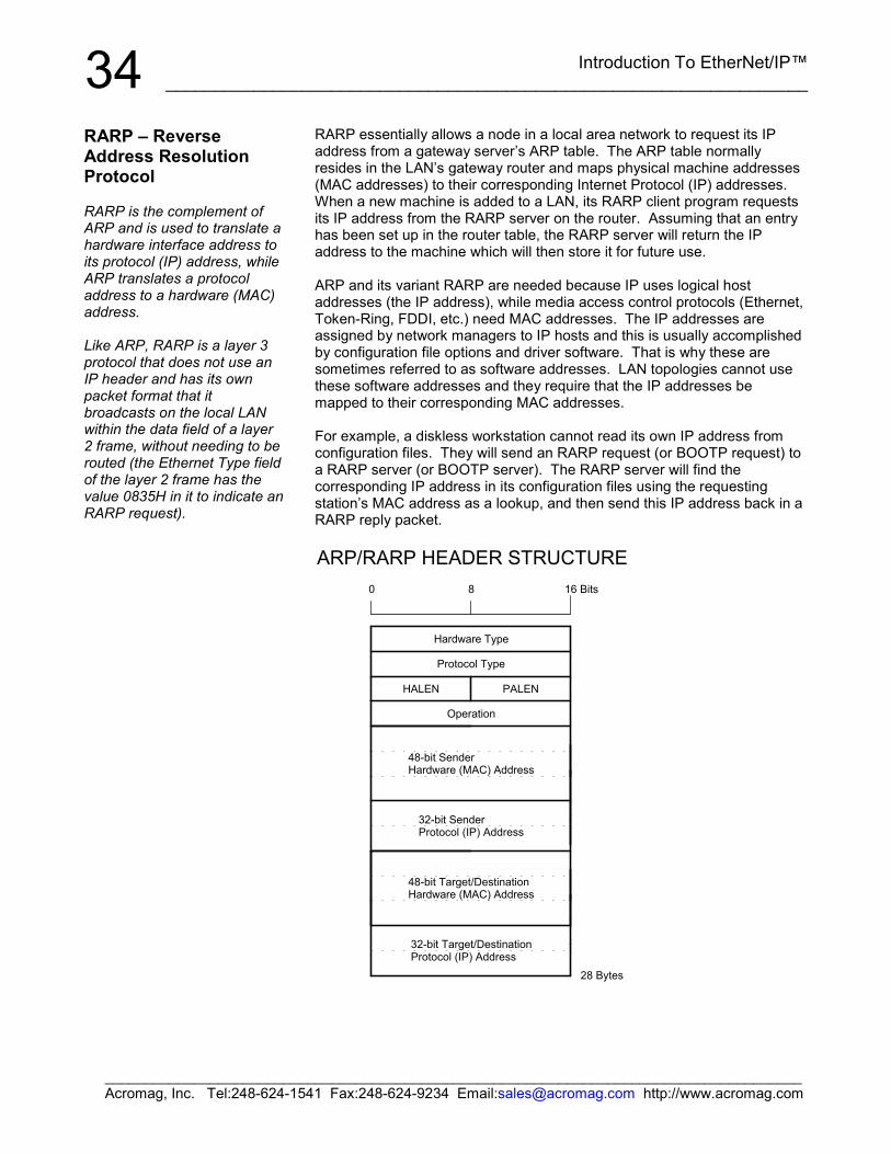
Introduction To EtherNet/IP™__________________________________________________________________
______________________________________________________________________________________Acromag, Inc. Tel:248-624-1541 Fax:248-624-9234 Email:[email protected] http://www.acromag.com
34RARP essentially allows a node in a local area network to request its IPaddress from a gateway server’s ARP table. The ARP table normallyresides in the LAN’s gateway router and maps physical machine addresses(MAC addresses) to their corresponding Internet Protocol (IP) addresses.When a new machine is added to a LAN, its RARP client program requestsits IP address from the RARP server on the router. Assuming that an entryhas been set up in the router table, the RARP server will return the IPaddress to the machine which will then store it for future use.
ARP and its variant RARP are needed because IP uses logical hostaddresses (the IP address), while media access control protocols (Ethernet,Token-Ring, FDDI, etc.) need MAC addresses. The IP addresses areassigned by network managers to IP hosts and this is usually accomplishedby configuration file options and driver software. That is why these aresometimes referred to as software addresses. LAN topologies cannot usethese software addresses and they require that the IP addresses bemapped to their corresponding MAC addresses.
For example, a diskless workstation cannot read its own IP address fromconfiguration files. They will send an RARP request (or BOOTP request) toa RARP server (or BOOTP server). The RARP server will find thecorresponding IP address in its configuration files using the requestingstation’s MAC address as a lookup, and then send this IP address back in aRARP reply packet.
0
.
.
.
.
.
.
Operation
8
PALEN
Bits
28 Bytes
32-bit Target/DestinationProtocol (IP) Address
48-bit Target/DestinationHardware (MAC) Address
HALEN
Hardware Type
Protocol Type
16
48-bit SenderHardware (MAC) Address
32-bit SenderProtocol (IP) Address
ARP/RARP HEADER STRUCTURE
RARP – ReverseAddress ResolutionProtocol
RARP is the complement ofARP and is used to translate ahardware interface address toits protocol (IP) address, whileARP translates a protocoladdress to a hardware (MAC)address.
Like ARP, RARP is a layer 3protocol that does not use anIP header and has its ownpacket format that itbroadcasts on the local LANwithin the data field of a layer2 frame, without needing to berouted (the Ethernet Type fieldof the layer 2 frame has thevalue 0835H in it to indicate anRARP request).
Introduction To EtherNet/IP™___________________________________________________________________
______________________________________________________________________________________Acromag, Inc. Tel:248-624-1541 Fax:248-624-9234 Email:[email protected] http://www.acromag.com
35ARP/RARP Header Field Definitions (Left-to-Right, Top-to-Bottom):
Hardware Type – Specifies a hardware interface type from which thesender requires a response. This is “1” for Ethernet.Protocol Type – This is the protocol type used at the network layer and isused to specify the type of high-level protocol address the sender hassupplied.Hardware Address Length (HALEN) – This is the hardware address lengthin bytes which is “6” for an Ethernet (MAC Address).Protocol Address Length (PALEN) – This is the protocol address length inbytes which is “4” for a TCP/IP (IP Address).Operation Code – This code is commonly used to indicate whether thepacket is an ARP request (1), or an ARP response (2). Valid codes are asfollows: 1 = ARP Request; 2 = ARP Response; 3 = RARP Request; 4 =RARP Response; 5 = Dynamic RARP Request; 6 = Dynamic RARP Reply;7 = Dynamic RARP Error; 8 = InARP Request; 9 = InARP Reply.Sender Hardware (MAC) Address – This is the 48-bit hardware (MAC)address of the source node.Sender Protocol (Software) Address – This is the 32-bit senders protocoladdress (the layer 3/network layer address—the IP address).Target/Destination Hardware (MAC) Address – Used in an RARPrequest. The RARP request response carries both the target hardwareaddress (MAC address) and layer 3 address (IP address).Target/Destination Protocol (Software) Address – Used in an ARPrequest. The ARP response carries both the target hardware address (MACaddress) and layer 3 address (IP address).
Most network stations will send out a gratuitous ARP request when they areinitializing their own IP stack. This is really an ARP request for their own IPaddress and is used to check for a duplicate IP address. If there is aduplicate IP address, then the stack does not complete its initialization.
The Data Link Layer or Host-to-Network Layer provides the protocol forconnecting the host to the physical network. Specifically, this layerinterfaces the TCP/IP protocol stack to the physical network for transmittingIP packets.
Recall from Figure 1 of the TCP/IP Stack section, how the various protocolsat each of the different layers are encapsulated (nested) into the data frameof the next lowest layer. That is, packets generally carry other packet typesinside them and their function is to often contain or encapsulate otherpackets. In this section, we will look at the lowest encapsulation layer (oftenreferred to as the data link layer or the MAC layer) where Ethernet resides.
Note that bits are transmitted serially with the least significant bit of eachbyte transmitted first at the physical layer. However, when the frame isstored on most computers, the bits are ordered with the least significant bitof each byte stored in the rightmost position (bits are generally transmittedright-to-left within the octets, and the octets are transmitted left-to-right).
DATA LINK (MAC)LAYER
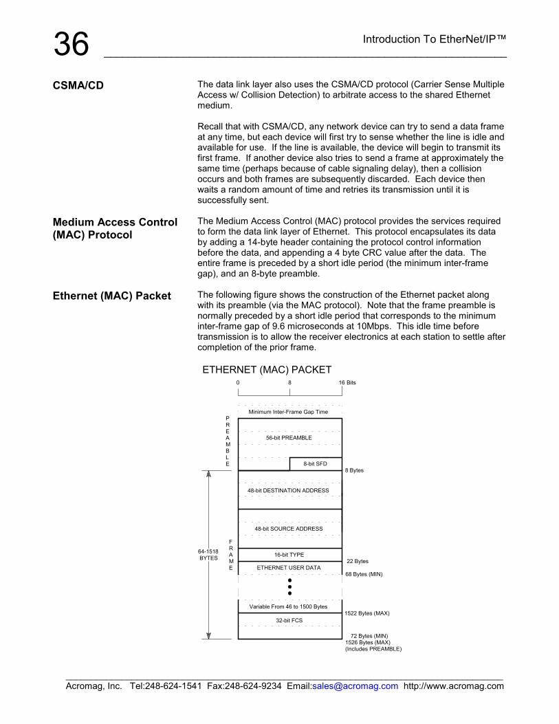
Introduction To EtherNet/IP™__________________________________________________________________
______________________________________________________________________________________Acromag, Inc. Tel:248-624-1541 Fax:248-624-9234 Email:[email protected] http://www.acromag.com
36The data link layer also uses the CSMA/CD protocol (Carrier Sense MultipleAccess w/ Collision Detection) to arbitrate access to the shared Ethernetmedium.
Recall that with CSMA/CD, any network device can try to send a data frameat any time, but each device will first try to sense whether the line is idle andavailable for use. If the line is available, the device will begin to transmit itsfirst frame. If another device also tries to send a frame at approximately thesame time (perhaps because of cable signaling delay), then a collisionoccurs and both frames are subsequently discarded. Each device thenwaits a random amount of time and retries its transmission until it issuccessfully sent.
The Medium Access Control (MAC) protocol provides the services requiredto form the data link layer of Ethernet. This protocol encapsulates its databy adding a 14-byte header containing the protocol control informationbefore the data, and appending a 4 byte CRC value after the data. Theentire frame is preceded by a short idle period (the minimum inter-framegap), and an 8-byte preamble.
The following figure shows the construction of the Ethernet packet alongwith its preamble (via the MAC protocol). Note that the frame preamble isnormally preceded by a short idle period that corresponds to the minimuminter-frame gap of 9.6 microseconds at 10Mbps. This idle time beforetransmission is to allow the receiver electronics at each station to settle aftercompletion of the prior frame.
8
FRAME
.
.
.
0
8-bit SFD8 Bytes
16 Bits
PREAMBLE
32-bit FCS
16-bit TYPE64-1518 BYTES
1522 Bytes (MAX)
72 Bytes (MIN)
68 Bytes (MIN)
1526 Bytes (MAX)(Includes PREAMBLE)
22 Bytes
Variable From 46 to 1500 Bytes
ETHERNET USER DATA
48-bit SOURCE ADDRESS
48-bit DESTINATION ADDRESS
56-bit PREAMBLE
Minimum Inter-Frame Gap Time
ETHERNET (MAC) PACKET
CSMA/CD
Medium Access Control(MAC) Protocol
Ethernet (MAC) Packet
Introduction To EtherNet/IP™___________________________________________________________________
______________________________________________________________________________________Acromag, Inc. Tel:248-624-1541 Fax:248-624-9234 Email:[email protected] http://www.acromag.com
37Ethernet (MAC) Frame Definitions (Left-to-Right & Top-to-Bottom):
Preamble & SFD (56-bits+8-bits SFD) – Technically, the preamble is notpart of the Ethernet frame, but is used to synchronize signals betweenstations. It is comprised of a pattern of 62 alternating 1’s & 0’s, followed bytwo set bits “11” (the last 8-bits of this pattern are actually referred to as theStart-of-Frame Delimiter or SFD byte). This 8-byte preamble/SFD is alsopreceded by a small idle period that corresponds to the minimum inter-framegap period of 9.6us (at 10Mbps). After transmitting a frame, the transmittermust wait for this period to allow the signal to propagate through thereceiver of its destination. The preamble allows the receiver at each stationto lock into the Digital Phase Lock Loop used to synchronize the receivedata clock to the transmit data clock. When the first bit of the preamblearrives, the receiver may be in an arbitrary state (out of phase) with respectto its local clock. It corrects this phase during the preamble and maymiss/gain a number of bits in the process. That is why the special pattern oftwo set bits (11) is used to mark the last two bits of the preamble. When itreceives these two bits, it starts assembling the bits into bytes forprocessing by the MAC layer. When using Manchester encoding at10Mbps, the 62 alternating 1/0 bits of the preamble will resemble a 5MHzsquare wave.Destination Address (48-bits) – This 6-byte address is the destinationEthernet address (MAC Address). It may address a single receiver node(unicast), a group of nodes (multicast), or all receiving nodes (broadcast).Source Address (48-bits) – This 6-byte address is the sender’s uniquenode address and is used by the network layer protocol to identify thesender and also to permit switches and bridges to perform address learning.Type (16-bits) – This 2-byte field provides a Service Access Point (SAP)and is used to identify the type of network layer protocol being carried. Thevalue 0800H would be used to indicate an IP network protocol, other valuesindicate other network layer protocols. For example, 0806H would indicatean ARP request, 0835H would indicate a RARP request. For IEEE 802.3LLC (Logical Link Control), this field may alternately be used to indicate thelength of the data portion of the packet.CRC Cyclic Redundancy Check (32-bits) – The CRC is added at the endof a frame to support error detection for cases where line errors ortransmission collisions result in a corrupted MAC frame. Any frame with aninvalid CRC is discarded by a MAC receiver without further processing andthe MAC protocol does not provide any other indication that a frame hasbeen discarded due to an invalid CRC.
The Ethernet standard dictates a minimum frame size which requires atleast 46 data bytes in a MAC frame. If a network layer tries to send lessthan 46 bytes of data, the MAC protocol adds the requisite number of 0bytes (null padding characters) to satisfy this requirement. The maximumdata size which may be carried in a MAC frame over Ethernet is 1500 bytes.
Any received frame less than 64 bytes is illegal and referred to as a “runt”.Runts may result from a collision and a receiver will discard all runt frames.
Any received frame which does not contain an integral multiple of octets(bytes) is also illegal (misaligned frame), as the receiver cannot compute theCRC for the frame and these will also be discarded by the receiver.
Any received frame greater than the maximum frame size is referred to as a“giant” and these frames are also discarded by an Ethernet receiver.
Ethernet (MAC) Packet
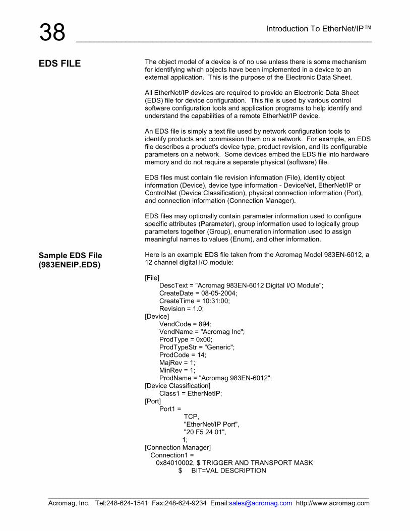
Introduction To EtherNet/IP™__________________________________________________________________
______________________________________________________________________________________Acromag, Inc. Tel:248-624-1541 Fax:248-624-9234 Email:[email protected] http://www.acromag.com
38The object model of a device is of no use unless there is some mechanismfor identifying which objects have been implemented in a device to anexternal application. This is the purpose of the Electronic Data Sheet.
All EtherNet/IP devices are required to provide an Electronic Data Sheet(EDS) file for device configuration. This file is used by various controlsoftware configuration tools and application programs to help identify andunderstand the capabilities of a remote EtherNet/IP device.
An EDS file is simply a text file used by network configuration tools toidentify products and commission them on a network. For example, an EDSfile describes a product's device type, product revision, and its configurableparameters on a network. Some devices embed the EDS file into hardwarememory and do not require a separate physical (software) file.
EDS files must contain file revision information (File), identity objectinformation (Device), device type information - DeviceNet, EtherNet/IP orControlNet (Device Classification), physical connection information (Port),and connection information (Connection Manager).
EDS files may optionally contain parameter information used to configurespecific attributes (Parameter), group information used to logically groupparameters together (Group), enumeration information used to assignmeaningful names to values (Enum), and other information.
Here is an example EDS file taken from the Acromag Model 983EN-6012, a12 channel digital I/O module:
[File]DescText = "Acromag 983EN-6012 Digital I/O Module";CreateDate = 08-05-2004;CreateTime = 10:31:00;Revision = 1.0;
[Device]VendCode = 894;VendName = "Acromag Inc";ProdType = 0x00;ProdTypeStr = "Generic";ProdCode = 14;MajRev = 1;MinRev = 1;ProdName = "Acromag 983EN-6012";
[Device Classification]Class1 = EtherNetIP;
[Port]Port1 =
TCP, "EtherNet/IP Port", "20 F5 24 01", 1;[Connection Manager] Connection1 = 0x84010002, $ TRIGGER AND TRANSPORT MASK $ BIT=VAL DESCRIPTION
EDS FILE
Sample EDS File(983ENEIP.EDS)
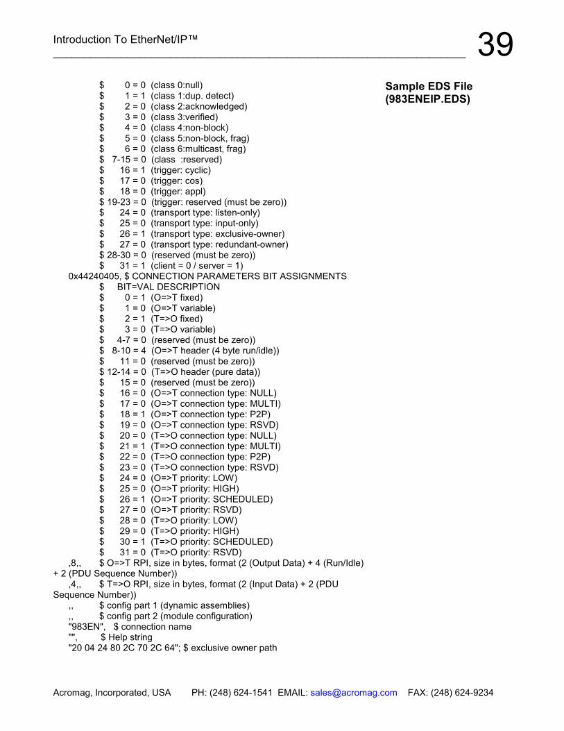
Introduction To EtherNet/IP™___________________________________________________________________
Acromag, Incorporated, USA PH: (248) 624-1541 EMAIL: [email protected] FAX: (248) 624-9234
39 $ 0 = 0 (class 0:null) $ 1 = 1 (class 1:dup. detect) $ 2 = 0 (class 2:acknowledged) $ 3 = 0 (class 3:verified) $ 4 = 0 (class 4:non-block) $ 5 = 0 (class 5:non-block, frag) $ 6 = 0 (class 6:multicast, frag) $ 7-15 = 0 (class :reserved) $ 16 = 1 (trigger: cyclic) $ 17 = 0 (trigger: cos) $ 18 = 0 (trigger: appl) $ 19-23 = 0 (trigger: reserved (must be zero)) $ 24 = 0 (transport type: listen-only) $ 25 = 0 (transport type: input-only) $ 26 = 1 (transport type: exclusive-owner) $ 27 = 0 (transport type: redundant-owner) $ 28-30 = 0 (reserved (must be zero)) $ 31 = 1 (client = 0 / server = 1) 0x44240405, $ CONNECTION PARAMETERS BIT ASSIGNMENTS $ BIT=VAL DESCRIPTION $ 0 = 1 (O=>T fixed) $ 1 = 0 (O=>T variable) $ 2 = 1 (T=>O fixed) $ 3 = 0 (T=>O variable) $ 4-7 = 0 (reserved (must be zero)) $ 8-10 = 4 (O=>T header (4 byte run/idle)) $ 11 = 0 (reserved (must be zero)) $ 12-14 = 0 (T=>O header (pure data)) $ 15 = 0 (reserved (must be zero)) $ 16 = 0 (O=>T connection type: NULL) $ 17 = 0 (O=>T connection type: MULTI) $ 18 = 1 (O=>T connection type: P2P) $ 19 = 0 (O=>T connection type: RSVD) $ 20 = 0 (T=>O connection type: NULL) $ 21 = 1 (T=>O connection type: MULTI) $ 22 = 0 (T=>O connection type: P2P) $ 23 = 0 (T=>O connection type: RSVD) $ 24 = 0 (O=>T priority: LOW) $ 25 = 0 (O=>T priority: HIGH) $ 26 = 1 (O=>T priority: SCHEDULED) $ 27 = 0 (O=>T priority: RSVD) $ 28 = 0 (T=>O priority: LOW) $ 29 = 0 (T=>O priority: HIGH) $ 30 = 1 (T=>O priority: SCHEDULED) $ 31 = 0 (T=>O priority: RSVD) ,8,, $ O=>T RPI, size in bytes, format (2 (Output Data) + 4 (Run/Idle)+ 2 (PDU Sequence Number)) ,4,, $ T=>O RPI, size in bytes, format (2 (Input Data) + 2 (PDUSequence Number)) ,, $ config part 1 (dynamic assemblies) ,, $ config part 2 (module configuration) "983EN", $ connection name "", $ Help string "20 04 24 80 2C 70 2C 64"; $ exclusive owner path
Sample EDS File(983ENEIP.EDS)